WO2024154351A1 - 信頼度決定システム、信頼度決定方法、及び信頼度決定装置 - Google Patents
信頼度決定システム、信頼度決定方法、及び信頼度決定装置 Download PDFInfo
- Publication number
- WO2024154351A1 WO2024154351A1 PCT/JP2023/001762 JP2023001762W WO2024154351A1 WO 2024154351 A1 WO2024154351 A1 WO 2024154351A1 JP 2023001762 W JP2023001762 W JP 2023001762W WO 2024154351 A1 WO2024154351 A1 WO 2024154351A1
- Authority
- WO
- WIPO (PCT)
- Prior art keywords
- reliability
- landmark
- update
- key frame
- map
- Prior art date
- Legal status (The legal status is an assumption and is not a legal conclusion. Google has not performed a legal analysis and makes no representation as to the accuracy of the status listed.)
- Ceased
Links
Images






Classifications
-
- G—PHYSICS
- G06—COMPUTING OR CALCULATING; COUNTING
- G06T—IMAGE DATA PROCESSING OR GENERATION, IN GENERAL
- G06T7/00—Image analysis
- G06T7/70—Determining position or orientation of objects or cameras
Definitions
- the present disclosure relates to a reliability determination system, a reliability determination method, and a reliability determination device.
- V-SLAM Visual Simultaneous Localization and Mapping
- Patent Document 1 discloses a V-SLAM technology that corrects a 3D map by increasing the reliability of map areas that were created in advance in the environmental map, while decreasing the reliability of map areas that are added during system operation.
- Patent Document 1 also discloses a technology that, assuming that a specific marker is placed in real space, increases the reliability of map areas created during system operation that are closer to the marker.
- Patent Document 1 does not mention anything about determining the reliability of data included in an environmental map other than determining the reliability of a map area based on the index of "whether or not the map area was created in advance" and determining the reliability of a map area based on the index of "the distance from a marker that was placed in advance.”
- the purpose of this disclosure is to disclose a new technology for determining the reliability of data included in an environmental map.
- the reliability determination system of the present disclosure includes an acquisition means for acquiring a first environmental image showing the environment in which a moving object moves, a posture determination means for determining a camera posture corresponding to the first environmental image according to an environmental map including one or more key frames that are a second environmental image different from the first environmental image, the camera postures corresponding to the key frames, and landmarks corresponding to feature points on the key frames, and an identification means for identifying the reliability of data included in the environmental map according to an update result of the environmental map, which is updated based on the result of the determination.
- the reliability determination method of the present disclosure is executed by a computer.
- the reliability determination method includes an acquisition step of acquiring a first environmental image showing an environment in which a moving object moves, a posture determination step of determining a camera posture corresponding to the first environmental image according to an environmental map including one or more key frames that are environmental images different from the first environmental image, camera postures corresponding to the key frames, and landmarks corresponding to feature points on the key frames, and a determination step of determining the reliability of data included in the environmental map according to an update result of the environmental map that is updated based on the result of the determination.
- the reliability determination device of the present disclosure includes an acquisition means for acquiring a first environmental image showing the environment in which a moving body moves, a posture determination means for determining a camera posture corresponding to the first environmental image according to an environmental map including one or more key frames that are environmental images different from the first environmental image, camera postures corresponding to the key frames, and landmarks corresponding to feature points on the key frames, and an identification means for identifying the reliability of data included in the environmental map according to an update result of the environmental map, which is updated based on the result of the determination.
- This disclosure provides a new technology for determining the reliability of data contained in an environmental map.
- FIG. 2 is a diagram illustrating an example of an outline of the operation of the reliability determination system according to the embodiment.
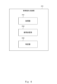
- FIG. 2 is a block diagram illustrating a functional configuration of a reliability determination system according to an embodiment.
- 1 is a block diagram illustrating a functional configuration of a reliability determination system that performs a map update process.
- FIG. 2 is a block diagram illustrating a functional configuration of a reliability determination device.
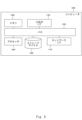
- FIG. 2 is a diagram illustrating an example of a hardware configuration of a computer that realizes the reliability determination system.
- 2 is a flowchart illustrating a process executed by a reliability determination system 2000 according to an embodiment.
- 10 is a flowchart illustrating in more detail the flow of a process executed by the reliability determination system.
- FIG. 1 is a block diagram illustrating a functional configuration of a reliability determination system that performs a map update process.
- FIG. 2 is a block diagram illustrating a functional configuration of a reliability determination device.
- FIG. 2 is a diagram
- FIG. 10 is a diagram illustrating an example of a configuration of landmark information.
- FIG. 11 is a diagram illustrating an example of a configuration of key frame information.
- 11 is a flowchart illustrating the flow of an attitude determination process.
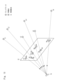
- FIG. 13 is a diagram illustrating an example of feature points and reprojection points.
- FIG. 1 is a diagram showing a graph representing pairs of feature points and reprojected points.
- FIG. 13 is a diagram illustrating an example of a graph including image nodes of key frames.
- 10 is a flowchart illustrating a flow of a map update process.
- 11 is a flowchart illustrating an example of a process for determining the reliability of a landmark position.
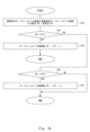
- 11 is a flowchart illustrating an example of a process for determining a reliability of a pose of a key frame.
- predetermined values such as predetermined values and threshold values are stored in advance in a memory unit that can be accessed by a device that uses the values.
- the memory unit is composed of one or more arbitrary number of storage devices.
- Fig. 1 is a diagram illustrating an example of an outline of a reliability determination system 2000 according to an embodiment.
- Fig. 1 is a diagram for facilitating understanding of the outline of the reliability determination system 2000, and the operation of the reliability determination system 2000 is not limited to that shown in Fig. 1.
- the reliability determination system 2000 performs an attitude determination process for determining an attitude to be associated with the environmental image 30, and a reliability determination process for determining the reliability of data included in the environmental map 40.
- the environmental image 30 is an image showing the environment in which the mobile body 10 travels.
- the input image 30 is, for example, a captured image generated by the camera 20.
- the camera 20 is provided on the mobile body 10.
- the mobile body 10 is, for example, a robot, a vehicle, or an aerial vehicle.
- the vehicle is, for example, an automobile or a motorcycle.
- the aerial vehicle is, for example, a drone.
- the mobile body 10 may be an object that moves autonomously, or may be an object that moves in response to operation by an operator.
- the mobile body 10 may also be an object that is capable of both autonomous movement and movement in response to operation.
- the reliability determination system 2000 acquires the environmental image 30 generated by the camera 20.
- the environmental image 30 is, for example, included in the time series data of the captured images generated by the camera 20.
- the reliability determination system 2000 can acquire 30 environmental images 30 per second.
- the reliability determination system 2000 may acquire only a portion of the multiple captured images generated by the camera 20 as the environmental images 30. For example, if the camera 20 is a 30 fps video camera, the reliability determination system 2000 can acquire 10 environmental images 30 per second by acquiring 1 out of every 3 captured images generated by the camera 20.
- the environmental map 40 includes landmark information 60 and key frame information 70.
- a key frame is a captured image generated by the camera 20. As described below, some of the multiple environmental images 30 acquired by the reliability determination system 2000 are added to the environmental map 40 as key frames.
- the key frame information 70 indicates the corresponding posture for each of the multiple key frames.
- the posture corresponding to a key frame is the posture of the camera 20 at the time when the key frame was generated.
- the attitude of the camera 20 is represented, for example, by a combination of the position and orientation of the camera 20.
- the position of the camera 20 is represented by three-dimensional coordinates that represent the position of the camera 20 in a specific three-dimensional space.
- the orientation of the camera 20 is represented, for example, by a combination of the azimuth angle and elevation angle of the camera 20 in that three-dimensional space.
- the "attitude corresponding to the captured image” is also expressed as the "attitude of the captured image”. Therefore, the "attitude corresponding to the key frame” is also expressed as the "attitude of the key frame”.
- the "attitude corresponding to the environmental image 30" is also expressed as the "attitude of the environmental image 30".
- the attitude of the camera 20 may be represented by either the position of the camera 20 or the orientation of the camera 20.
- the landmark information 60 indicates the position of each of one or more landmarks 50.
- a landmark 50 is a point in the above three-dimensional space that corresponds to a feature point included in a key frame.
- a landmark 50 is a point on an object captured on a key frame, and corresponds to a feature point included in that key frame.
- a feature point is a characteristic point detected from an image.
- a feature point is detected according to the gradient of brightness in an image or the amount of change in features in an image.
- the position of a landmark 50 is expressed, for example, by three-dimensional coordinates that indicate the position of the landmark 50 in the above three-dimensional space.
- a landmark 50 can also be expressed as a feature point whose three-dimensional position has been specified among the feature points detected from an environmental image.
- landmark L is observed by captured image I" or “captured image I observes landmark L.”
- the reliability determination system 2000 uses the environmental image 30 and the environmental map 40 to perform a posture determination process for the environmental image 30.
- the reliability determination system 2000 uses a method such as bundle adjustment to determine the posture to be associated with the environmental image 30.
- the reliability determination system 2000 further performs a reliability determination process to determine the reliability of the data included in the environmental map 40.
- the data for which reliability is determined is, for example, the position of the landmark 50.
- Another example of the data for which reliability is determined is the posture corresponding to the key frame.
- the reliability of the data contained in the environmental map 40 is determined based on the results of updating that data. For example, when the position of a landmark 50 is updated, if the amount of change in the position of the landmark 50 due to the update is small, there is a high probability that the position of the landmark 50 has been accurately estimated. Therefore, for example, the reliability determination system 2000 determines the reliability of the landmark 50 based on the amount of change in the position of the landmark 50 due to the update.
- the reliability determination system 2000 determines the reliability of the keyframe based on the amount of change in the posture of the keyframe due to the update.
- one or more of the multiple environmental images 30 acquired by the reliability determination system 2000 may be added to the environmental map 40 as new key frames.
- the reliability determination system 2000 may perform a map update process. For example, the reliability determination system 2000 updates the environmental map 40 by updating the positions of the landmarks 50 and the orientations of the key frames using a method such as bundle adjustment.
- the reliability of the data included in the environmental map 40 is determined based on the result of updating the data. In this manner, according to the reliability determination system 2000, a new technique for determining the reliability of the data included in the environmental map 40 is provided.
- some of the data included in the environmental map 40 is repeatedly updated based on the results of sensing using the camera 20, i.e., the environmental image 30 obtained from the camera 20. Since the values of data that are repeatedly updated in this way change repeatedly, it is difficult to determine the reliability in advance. It is also difficult to determine the reliability in advance for data that is not initially included in the environmental map 40 and is dynamically generated as a result of sensing using the camera 20.
- the reliability of data included in the environmental map 40, whose values are updated is dynamically determined. Therefore, the reliability can be easily determined even for data that is updated. Also, because the reliability is dynamically determined, the reliability can be easily determined even for data that is dynamically generated. Furthermore, because the reliability is determined based on the results of updating the data, the reliability of the data can be determined more accurately compared to cases where the reliability of the data is determined in advance.
- determining the reliability of the data included in the environmental map 40 has the effect of, for example, making it possible to increase the accuracy of the process in which the data included in the environmental map 40 is used, compared to the accuracy of the process in the case where the reliability of the data is not determined. For example, by performing a map update process using key frames or landmarks with high reliability, the accuracy of the map update process can be increased compared to the accuracy of the map update process in the case where key frames or landmarks with high reliability are not used. The same effect can be obtained with the attitude update process.
- the reliability of the data included in the environmental map 40 is accurately determined.
- the reliability of the data included in the environmental map 40 is determined more accurately than when the reliability is determined in advance. Therefore, according to the reliability determination system 2000, the accuracy of processing using data included in the environmental map 40 can be more reliably increased compared to the accuracy of such processing when the reliability of the data included in the environmental map 40 is determined in advance.
- the reliability determination system 2000 of this embodiment is described in more detail below.
- ⁇ Example of functional configuration> 2 is a block diagram illustrating a functional configuration of a reliability determination system 2000 according to an embodiment.
- the reliability determination system 2000 includes an acquisition unit 2020, an attitude determination unit 2040, and a determination unit 2080.
- the acquisition unit 2020 acquires an environmental image 30.
- the attitude determination unit 2040 executes a determination process for determining the position of the environmental image 30 using an environmental map 40.
- the determination unit 2080 calculates the reliability of the data included in the environmental map 40 based on an update result of the data included in the environmental map 40.
- the reliability determination system 2000 When the reliability determination system 2000 further performs a map update process, the reliability determination system 2000 further has a functional configuration unit that performs the map update process.
- FIG. 3 is a block diagram illustrating an example of the functional configuration of the reliability determination system 2000 that performs the map update process.
- the reliability determination system 2000 further has a map update unit 2060.
- the map update unit 2060 executes a map update process that updates the position of the key frame and the position of the landmark 50.
- Each functional component included in the reliability determination system 2000 may be realized by one device.
- the device in which each functional component included in the reliability determination system 2000 is realized is called a reliability determination device.
- FIG. 4 is a block diagram illustrating an example of the functional configuration of a reliability determination device.
- the reliability determination device 3000 has an acquisition unit 2020, an attitude determination unit 2040, and an identification unit 2080, similar to the reliability determination system 2000.
- the reliability determination device 3000 that executes the map update process further has a map update unit 2060, similar to the reliability determination system 2000 of FIG. 3.
- Each functional component of the reliability determination system 2000 may be realized by hardware that realizes each functional component (e.g., a hardwired electronic circuit, etc.), or may be realized by a combination of hardware and software (e.g., a combination of an electronic circuit and a program that controls it, etc.). The case where each functional component of the reliability determination system 2000 is realized by a combination of hardware and software will be further described below.
- FIG. 5 is a block diagram illustrating an example of a hardware configuration of a computer 1000 that realizes the reliability determination system 2000.
- the computer 1000 is any computer.
- the computer 1000 may be provided inside the mobile body 10 or outside the mobile body 10.
- the computer 1000 is, for example, a computer that realizes a control device that controls the operation of the mobile body 10, or a computer that realizes a navigation device provided in the mobile body 10.
- the computer that realizes the control device is, for example, a semiconductor chip such as a SoC (System on Chip).
- SoC System on Chip
- the computer 1000 is provided outside the mobile body 10, the computer 1000 is, for example, a PC (Personal Computer), a server machine, or a mobile terminal.
- the computer 1000 may be a dedicated computer designed to realize the reliability determination system 2000, or may be a general-purpose computer.
- each function of the reliability determination system 2000 is realized on the computer 1000.
- the application is composed of a program for realizing each functional component of the reliability determination system 2000.
- the method of acquiring the program is arbitrary.
- the program can be acquired from a storage medium (such as a DVD disk or USB memory) on which the program is stored.
- the program can be acquired by downloading the program from a server device that manages the storage device on which the program is stored.
- Computer 1000 has bus 1020, processor 1040, memory 1060, storage device 1080, input/output interface 1100, and network interface 1120.
- Bus 1020 is a data transmission path for processor 1040, memory 1060, storage device 1080, input/output interface 1100, and network interface 1120 to transmit and receive data to and from each other.
- the method of connecting processor 1040 and the like to each other is not limited to bus connection.
- the processor 1040 is one of various processors, such as a CPU (Central Processing Unit), a GPU (Graphics Processing Unit), an FPGA (Field-Programmable Gate Array), or a DSP (Digital Signal Processor).
- the memory 1060 is a primary storage device realized using RAM (Random Access Memory) or the like.
- the storage device 1080 is an auxiliary storage device realized using a hard disk, SSD (Solid State Drive), memory card, or ROM (Read Only Memory) or the like.
- the input/output interface 1100 is an interface for connecting the computer 1000 to an input/output device.
- an input device such as a keyboard and an output device such as a display device are connected to the input/output interface 1100.
- the network interface 1120 is an interface for connecting the computer 1000 to a network.
- This network may be a LAN (Local Area Network) or a WAN (Wide Area Network).
- the storage device 1080 stores a program that realizes each functional component of the reliability determination system 2000 (a program that realizes the application described above).
- the processor 1040 reads this program into the memory 1060 and executes it to realize each functional component of the reliability determination system 2000.
- the reliability determination system 2000 may be realized by one computer 1000, or may be realized by multiple computers 1000. In the latter case, the configuration of each computer 1000 does not need to be the same, and can be different from each other.
- each functional component included in the reliability determination system 2000 can be realized by a single device called the reliability determination device 3000.
- the hardware configuration of the reliability determination device 3000 is similar to the hardware configuration of the reliability determination system 2000.
- ⁇ Processing flow> 6 is a flowchart illustrating the flow of processing executed by the reliability determination system 2000 of the embodiment.
- the acquisition unit 2020 acquires the environmental image 30 (S002).
- the attitude determination unit 2040 executes a determination process for determining the position of the environmental image 30 using the environmental map 40 (S004).
- the specification unit 2080 calculates the reliability of the data included in the environmental map 40 based on the update result of the data included in the environmental map 40 (S006).
- the reliability determination system 2000 further executes a map update process.
- FIG. 7 is a flowchart illustrating in more detail the flow of processing executed by the reliability determination system 2000 of the embodiment.
- the processing from S102 to S118 constitutes a loop processing L1 that is repeatedly executed until a predetermined termination condition is satisfied.
- the reliability determination system 2000 determines whether or not the predetermined termination condition is satisfied. If the predetermined termination condition is not satisfied, the processing in FIG. 7 proceeds to S104. On the other hand, if the predetermined termination condition is satisfied, the processing in FIG. 7 ends.
- the termination condition is that "a specified user operation is performed.”
- Another example of the termination condition is that "the operation of the mobile body 10 ends.”
- the acquisition unit 2020 acquires the environmental image 30 (S104).
- the attitude determination unit 2040 executes attitude determination processing (S106).
- the map update unit 2060 determines whether or not to add the environmental image 30 to the environmental map 40 as a new key frame (S108). If it is determined that "the environmental image 30 is not to be added to the environmental map 40 as a new key frame" (S108: NO), the processing in FIG. 7 proceeds to S116. Since S116 is the end of the loop processing L1, the processing in FIG. 7 proceeds to S102.
- the map update unit 2060 adds the environmental image 30 to the environmental map 40 as a new key frame (S110).
- the map update unit 2060 executes a map update process (S112).
- the identification unit 2080 executes a reliability determination process (S114). Since S116 is the end of the loop process L1, the process in FIG. 7 proceeds to S102.
- the process flow executed by the reliability determination system 2000 is not limited to the flow shown in FIG. 7.
- the reliability determination process is performed each time the map update process is executed.
- the reliability determination process does not necessarily have to be executed each time the map update process is executed.
- the reliability determination process may be executed each time the map update process is executed a predetermined number of times.
- the reliability determination process may be executed immediately after the attitude determination process (S106).
- FIG. 8 is a diagram illustrating an example of the configuration of the landmark information 60.
- the landmark information 60 has four columns: a landmark identifier 62, a position 64, a key frame identifier 66, and a feature point 68.
- the landmark identifier 62 indicates an identifier assigned to the landmark 50.
- the position 64 indicates the three-dimensional position of the landmark 50.
- the key frame identifier 66 indicates an identifier of a key frame having a feature point corresponding to the landmark 50.
- the feature point 68 indicates the position of the feature point on the corresponding key frame.
- the first row of the landmark information 60 in FIG. 8 indicates that the three-dimensional position of the landmark L1 is (x1, y1, z1), and that the feature point (u11, v11) on the key frame F1 corresponds to the landmark L1.
- one landmark 50 may correspond to feature points in multiple key frames.
- feature point (u11,v11) on key frame F1 and feature point (u21,v21) on key frame F2 each correspond to landmark L1. Therefore, the landmark information 60 in Figure 8 has records (L1,(x1,y1,z1),F1,(u11,v11)) and (L1,(x1,y1,z1),F2,(u21,v21)) indicating landmark L1.
- FIG. 9 is a diagram illustrating the configuration of keyframe information 70.
- Keyframe information 70 has three columns: keyframe identifier 72, path 74, and attitude 76.
- Keyframe identifier 72 indicates the identifier assigned to the keyframe.
- Path 74 indicates the path of the image file of the keyframe.
- Attitude 76 indicates the attitude of the keyframe.
- the first line in FIG. 9 indicates that "keyframe F1 is an image file identified by the path "usr/.../img01.jpg"" and that "the attitude of keyframe F1 is position (x1, y1, z1) and orientation ( ⁇ 1, ⁇ 1)."
- the orientation is expressed as a combination of azimuth and elevation.
- the acquisition unit 2020 acquires the environmental image 30 (S002, S104).
- the environmental image 30 is transmitted from the camera 20 to the reliability determination system 2000.
- the acquisition unit 2020 acquires the environmental image 30 by receiving the environmental image 30 transmitted from the camera 20.
- the environmental image 30 may be transmitted by something other than the reliability determination system 2000.
- a device other than the camera 20 provided in the moving body 10 may transmit the environmental image 30 to the reliability determination system 2000.
- this device is a control device that controls the operation of the moving body 10.
- the camera 20 stores the environmental image 30 in a storage unit accessible from the reliability determination system 2000.
- the acquisition unit 2020 acquires the environmental image 30 by reading the environmental image 30 from the storage unit.
- the camera 20 generates a plurality of environmental images 30.
- the reliability determination system 2000 may acquire the environmental images 30 one by one, or may acquire two or more environmental images 30 together.
- the attitude determination unit 2040 executes attitude determination processing to determine the attitude of the environmental image 30 (S004, S106).
- the attitude determination processing will be specifically illustrated below.
- FIG. 10 is a flowchart illustrating the flow of the attitude determination processing.
- the attitude determination unit 2040 associates an assumed attitude with the environmental image 30 (S202).
- the associated attitude is also expressed as an "assumed pose.”
- an existing method used in V-SLAM or the like can be used as a method for determining an assumed attitude for a new environmental image.
- the posture determination unit 2040 detects a plurality of feature points from the environmental image 30 (S204).
- the posture determination unit 2040 identifies a corresponding landmark 50 for one or more feature points included in the environmental image 30 (S206).
- the landmark 50 corresponding to the feature points of the environmental image 30 can be identified, for example, by performing feature point matching between the environmental image 30 and a key frame. Specifically, when feature point P1 of the environmental image 30 matches feature point Q1 of a certain key frame, the posture determination unit 2040 identifies the landmark 50 corresponding to feature point Q1 of that key frame as the landmark 50 corresponding to feature point P1 of the environmental image 30.
- information on the landmark 50 corresponding to the feature points of the key frame is indicated in the landmark information 60.
- some of the feature points included in the environmental image 30 may not correspond to any of the landmarks 50 included in the environmental map 40.
- a new corresponding landmark 50 may be generated by a map update process.
- the attitude determination unit 2040 reprojects each of the identified landmarks 50 onto the environmental image 30 (S208).
- the process of "reprojecting the landmarks 50 onto the captured image” is a process of projecting the landmarks 50 onto the captured image, assuming that both the attitude of the captured image and the three-dimensional position of the landmarks 50 are correct, to identify a theoretical point on the captured image at which the landmarks 50 are observed.
- the theoretical point is also expressed as a "re-projected point.”
- the process of "projecting the landmarks 50 onto the captured image” is a process of virtually arranging the landmark, the captured image, and the camera having the attitude associated with the captured image in three-dimensional space, and calculating a point at which a straight line connecting the camera and the landmark passes through the captured image.
- the attitude determination unit 2040 obtains, for each landmark 50 observed in the environmental image 30, a pair of a feature point on the environmental image 30 corresponding to the landmark 50 and a re-projected point on the environmental image 30 obtained by reprojecting the landmark 50.
- FIG. 11 is a diagram illustrating feature points and reprojection points.
- corresponding landmarks L1 to L6 are identified.
- reprojection points R1 to R6 are obtained. Therefore, six pairs of feature points and reprojection points are obtained: (P1, R1), (P2, R2), (P3, R3), (P4, R4), (P5, R5), and (P6, R6).
- Pairs of feature points and reprojected points can also be expressed by a graph.
- FIG. 12 is a diagram showing a graph expressing pairs of feature points and reprojected points.
- the topmost node and the bottommost node represent the landmark 50 and the captured image, respectively.
- the topmost node and the bottommost node are also expressed as the "landmark node” and the "image node", respectively.
- Graph 80 in FIG. 12 has a node for the environmental image 30 as the image node.
- Edges represent the correspondence between feature points on an image node and landmarks that have three-dimensional positions.
- the image node of environmental image 30 and the landmark node of landmark L1 are connected by an edge representing the pair (P1, R1). This indicates that feature point P1 included in environmental image 30 corresponds to landmark L1, and that reprojection point R1 can be obtained by reprojecting landmark L1 onto environmental image 30.
- the orientation determination unit 2040 determines the orientation of the environmental image 30 based on the reprojection error obtained from each of multiple pairs of feature points and reprojection points (S210).
- the reprojection error obtained from a pair of feature points and reprojection points is represented as the distance between the feature points and the reprojection points.
- the orientation determination unit 2040 identifies the orientation of the environmental image 30 that minimizes an objective function determined based on the reprojection error, and determines the identified orientation as the orientation to be associated with the environmental image 30.
- the attitude determination unit 2040 identifies the value of each piece of data that minimizes the objective function by adjusting the value of one or more pieces of data that affect the magnitude of the reprojection error. In this way, a method such as bundle adjustment can be applied to the process of identifying the value of each piece of data that minimizes the objective function based on the reprojection error by adjusting the value of each piece of data that affects the magnitude of the reprojection error.
- the data to be adjusted may be only the attitude of the environmental image 30, or may include data other than the attitude of the environmental image 30.
- the data to be adjusted includes the positions of each landmark 50 observed by the environmental image 30.
- the attitude determination unit 2040 adjusts the attitude of the environmental image 30 and the positions of each landmark 50 to identify the attitude of the environmental image 30 and the positions of each landmark 50 that minimize the objective function based on the reprojection error.
- the data to be adjusted may include the posture of a key frame.
- the posture determination unit 2040 reprojects the landmarks 50 not only on the environmental image 30 but also on the key frame to obtain pairs of feature points included in the key frame and the reprojected points of the landmarks 50 that correspond to those feature points. In this way, cases in which pairs of feature points and reprojected points are obtained for the key frame as well can be represented by adding an image node of the key frame to the graph 80 described above.
- the graph 80 in FIG. 13 is a diagram illustrating an example of a graph 80 including image nodes of key frames.
- the graph 80 in FIG. 13 has image nodes for each of the key frames F1 and F2.
- one landmark node is connected to two edges. This indicates that one landmark 50 is observed in two captured images.
- the landmark node of the landmark L1 is connected to the image node of the key frame F1 by an edge representing the pair (P11, R11).
- the landmark node of the landmark L1 is connected to the image node of the environmental image 30 by an edge representing the pair (P1, R1).
- the posture determination unit 2040 identifies the posture of the environmental image 30 and the posture of each key frame that minimizes the objective function based on the reprojection error obtained from pairs of feature points and reprojection points represented by each edge of the graph 80 in FIG. 13. This determines the posture of the environmental image 30. Also, the posture of each key frame is updated in the environmental map 40.
- either one of the landmark position and the key frame posture may be treated as the adjustment target, or both may be treated as the adjustment targets.
- the posture determination unit 2040 identifies the posture of the environmental image 30, the posture of each key frame, and the position of each landmark 50 that minimizes the objective function based on the reprojection error obtained from pairs of feature points and reprojection points represented by each edge in the graph 80 of FIG. 13. This determines the posture of the environmental image 30. Also, the posture of each key frame and the position of each landmark 50 are updated in the environmental map 40.
- the map update unit 2060 determines whether or not to add the environmental image 30 to the environmental map 40 as a new key frame (S108).
- various conditions can be adopted as the conditions for adding the environmental image 30 to the environmental map 40 as a new key frame.
- the conditions for adding the environmental image 30 to the environmental map 40 as a new key frame are also referred to as "addition conditions.”
- the additional condition is that "the difference between the posture of the environmental image 30 and the posture of the latest keyframe included in the environmental map 40 satisfies a predetermined condition."
- the predetermined condition is, for example, that "the distance between the position of the environmental image 30 and the position of the latest keyframe included in the environmental map 40 is greater than or equal to a threshold.”
- Another example of the predetermined condition is that "the difference between the orientation of the environmental image 30 and the orientation of the latest keyframe included in the environmental map 40 is greater than or equal to a threshold.”
- Another example of an additional condition is that "the number of landmarks 50 observed in the environmental image 30 is less than or equal to a threshold value.”
- the map update unit 2060 adds the environmental image 30 to the environmental map 40 as a new key frame (S110).
- the map update unit 2060 adds a record representing the environmental image 30 to the key frame information 70.
- the key frame identifier 72 of the record to be added indicates the key frame identifier assigned to the environmental image 30.
- the path 74 of the record to be added indicates the path of the environmental image 30.
- the attitude 76 of the record to be added indicates the attitude of the environmental image 30 determined by the attitude determination process.
- the map update unit 2060 adds records indicating the correspondence between the feature points of the environmental image 30 and the landmarks 50 to the landmark information 60. Specifically, the correspondence between the feature points on the environmental image 30 identified in the posture determination process and the landmarks 50 is added to the landmark information 60. For example, in the example of Figure 10, landmarks L1 to L6 are identified as the landmarks 50 corresponding to feature points P1 to P6 of the environmental image 30, respectively. Therefore, the map update unit 2060 adds records indicating these correspondences to the landmark information 60.
- the map update unit 2060 updates the environmental map 40 when the environmental image 30 is added to the environmental map 40 as a key frame (S112).
- the environmental image 30 added to the environmental map 40 as a key frame is also referred to as a new key frame.
- key frames other than the new key frame are also referred to as existing key frames. Updating the environmental map 40 includes updating the attitude of the key frame and updating the position of the landmark 50. Key frames to be updated include not only existing key frames but also new key frames.
- the map update unit 2060 executes the map update process as follows.
- FIG. 14 is a flowchart illustrating the flow of the map update process.
- the map update unit 2060 generates new landmarks 50 for one or more feature points included in the new key frame for which no corresponding landmark 50 was identified in the posture determination process (S302).
- the position of the new landmark 50 can be determined, for example, by using triangulation.
- the map update unit 2060 performs feature point matching between the new keyframe and the existing keyframe to detect feature points in the existing keyframe that match feature points in the new keyframe for which no corresponding landmark 50 has been identified.
- the map update unit 2060 then identifies three-dimensional positions represented by these feature points by triangulation based on the orientation of the new keyframe and the positions of the feature points in the new keyframe, as well as the orientation of the existing keyframe and the positions of the feature points in the existing keyframe.
- the identified three-dimensional positions are then determined as the positions of the new landmarks 50 corresponding to these feature points.
- Information on the new landmarks 50 is added to the landmark information 60.
- map update unit 2060 assigns identifier Lk to the newly generated landmark 50.
- the map update unit 2060 generates pairs of feature points and reprojection points for each of the new keyframe and one or more existing keyframes used to update the environmental map 40 (S304). This results in a graph 80 similar to the graph 80 illustrated in FIG. 13.
- the map update unit 2060 updates the position of the landmark 50, the orientation of the new key frame, and the orientation of the existing key frame based on the reprojection error of each pair of feature point and reprojection point (S306). For example, the map update unit 2060 identifies the position of the landmark 50, the orientation of the new frame, and the orientation of the existing key frame that minimizes an objective function determined based on the reprojection error, and updates the environmental map 40 with the identified values. As described above, methods such as bundle adjustment can be used to identify the position of the landmark 50 and the orientation of the image that minimizes an objective function determined based on the reprojection error.
- the map update unit 2060 may update the positions of the landmarks 50 based on the reprojection error, and then recalculate the reprojection error for each pair of feature point and reprojection point, and exclude landmarks 50 whose reprojection error is equal to or greater than a threshold value from the environmental map 40. This makes it possible to exclude landmarks 50 with large errors due to the update as outliers from the environmental map 40.
- the identification unit 2080 determines the reliability of the data included in the environmental map 40 based on the update result of the data included in the environmental map 40 (S006, S114).
- the data for which the reliability is determined is, for example, the posture of the key frame or the position of the landmark 50.
- the determination of the reliability of the position of the landmark 50 will first be described.
- the positions of the landmarks 50 may be updated by a map update process.
- the identification unit 2080 determines the reliability of the position of each landmark 50 that is the target of update in the map update process based on the results of the update.
- the positions of the landmarks 50 may be updated by an attitude determination process.
- the identification unit 2080 determines the reliability of the position of each landmark 50 that is the target of update in the attitude determination process based on the results of the update.
- the identification unit 2080 determines the reliability of the position of the landmark 50 based on the difference between the position of the landmark 50 before the update and the position of the landmark 50 after the update. In other words, the identification unit 2080 determines the reliability of the position of the landmark 50 based on the amount of change in the position of the landmark 50 due to the update.
- the amount of change in the position of the landmark 50 due to the update is represented, for example, by the distance between the position of the landmark 50 before the update and the position of the landmark 50 after the update.
- the identification unit 2080 calculates the amount of change in position due to the update for each landmark 50 that is the target of the update. Then, the more updates for each landmark 50 in which the amount of change in position is below a threshold, the greater the value the identification unit 2080 sets to the reliability of the position of that landmark 50. In this way, the more updates with small amounts of change in position are performed for a landmark 50, the higher the reliability of its position. For example, the identification unit 2080 adds a predetermined value to the reliability of the position of the landmark 50 each time an update with small amounts of change in position is performed for each landmark 50.
- the identification unit 2080 may perform a process to decrease the reliability of the landmark 50 in addition to or instead of the process to increase the reliability of the landmark 50. For example, the identification unit 2080 subtracts a predetermined value from the reliability of the position of each landmark 50 each time an update that causes a large amount of change in the position is performed.
- the predetermined value added to the reliability and the predetermined value subtracted from the reliability may be the same value or may be different values.
- FIG. 15 is a flowchart illustrating the process flow for determining the reliability of the position of a landmark 50.
- the identification unit 2080 executes the process of FIG. 15 for each landmark 50 that is to be updated.
- the landmark 50 that is the subject of the reliability determination process is represented as Li.
- the identification unit 2080 calculates the distance DLi between the position of the landmark Li before the update and the position of the landmark Li after the update (S402). The identification unit 2080 determines whether the distance DLi is less than or equal to the threshold TL1 (S404). If the distance DLi is less than or equal to the threshold TL1 (S404: YES), the identification unit 2080 increases the reliability CLi of the landmark Li by a (S406), where a>0.
- the identification unit 2080 determines whether the distance DLi is greater than or equal to the threshold TL2 (S408), where TL1 ⁇ TL2. If the distance DLi is greater than or equal to the threshold TL2 (S408: YES), the identification unit 2080 reduces the reliability CLi of the landmark Li by b (S410), where b>0. If the distance DLi is not greater than or equal to the threshold TL2 (S408: NO), the processing of FIG. 15 ends.
- the number of key frames in which the landmark 50 is observed may be further taken into consideration when determining the reliability of the position of the landmark 50.
- the number of key frames in which the landmark L is observed is also referred to as the "number of observations of the landmark L.”
- the reliability of the position of the landmark 50 is represented by (CLi, NOi), which is a combination of the value CLi, which is set based on the amount of change in position due to updates, and the number of observations of the landmark 50, NOi.
- the reliability of the landmark 50 may be represented by a single value calculated based on the aforementioned value CLi and the number of observations of the landmark 50, NOi.
- the reliability of the landmark 50 is represented by CLi*NOi, which is the value obtained by multiplying CLi by NOi, or the weighted sum of CLi and NOi.
- the posture of a keyframe may be updated by a map update process.
- the identification unit 2080 determines the reliability of the posture of each keyframe that is the target of updating in the map update process based on the result of the update.
- the posture of a keyframe may be updated by a posture determination process.
- the identification unit 2080 determines the reliability of the posture position of each keyframe that is the target of updating in the posture determination process based on the result of the update.
- the identification unit 2080 determines the reliability of the posture of the keyframe based on the difference between the posture of the keyframe before and after the update. In other words, the identification unit 2080 determines the reliability of the posture of the keyframe based on the amount of change in the posture of the keyframe due to the update.
- the determination unit 2080 calculates the amount of change in the posture of the key frame.
- the determination unit 2080 sets a higher value for the reliability of a key frame the more updates that result in the amount of change in the posture of the key frame being below a threshold. In this way, the more updates with small amounts of change in posture are performed for a key frame, the higher the reliability of the posture.
- the determination unit 2080 adds a predetermined value to the reliability of the posture of the key frame each time an update with small amounts of change in posture is performed for each key frame.
- the determination unit 2080 may perform a process to decrease the reliability of the posture of a key frame in addition to or instead of the process to increase the reliability of the posture of a key frame. For example, the determination unit 2080 subtracts a predetermined value from the reliability of the posture of a key frame each time an update that causes a large amount of change in the posture is performed for each key frame.
- the predetermined value added to the reliability and the predetermined value subtracted from the reliability may be the same value or may be different values.
- the amount of change in the posture of a key frame is expressed by the amount of change in the position of the key frame.
- the identification unit 2080 calculates the distance between the position of the key frame before the update and the position of the key frame after the update as a value representing the amount of change in the posture of the key frame.
- the change in the posture of a key frame may be represented by the change in the position of the key frame and the change in the orientation of the key frame.
- FIG. 16 is a flowchart illustrating the process flow for determining the reliability of the posture of a key frame.
- the identification unit 2080 executes the process of FIG. 16 for each key frame to be updated.
- the key frame to be subjected to the reliability determination process is denoted as Fi.
- the determination unit 2080 calculates the difference DFi between the posture of the keyframe Fi before the update and the posture of the keyframe Fi after the update (S502). The determination unit 2080 determines whether the difference DFi is equal to or less than the threshold TF1 (S504). If the difference DFi is equal to or less than the threshold TF1 (S504: YES), the determination unit 2080 increases the reliability CFi of the keyframe Fi by c (S506), where c>0.
- the determination unit 2080 determines whether the difference DFi is greater than or equal to the threshold TF2 (S508), where TF1 ⁇ TF2. If the difference DFi is greater than or equal to the threshold TF2 (S508: YES), the determination unit 2080 reduces the confidence CFi of the posture of the keyframe Fi by d (S510), where d>0. If the difference DFi is not greater than or equal to the threshold TF2 (S508: NO), the processing of FIG. 16 ends.
- the reliability of the posture of a keyframe may be determined by further taking into account the reliability of the position of the landmark 50 observed by the keyframe.
- the identification unit 2080 reflects the number NLi of the landmarks 50 having high reliability in their positions among the landmarks 50 observed by the keyframe Fi in the reliability of the posture of the keyframe Fi.
- the reliability of the posture of the keyframe Fi is represented by (CFi, NLi), which is a combination of a value CFi determined based on the amount of change in the posture and the number NLi of the landmarks 50 having high reliability in their positions among the landmarks 50 observed by the keyframe Fi.
- the reliability of the posture of a keyframe may be represented by a single value calculated based on CFi and NLi.
- the reliability of the posture of a keyframe may be represented by, for example, CFi*NLi, which is the value obtained by multiplying CFi by NLi, or a weighted sum of CFi and NLi.
- a landmark 50 with high positional reliability is, for example, a landmark 50 whose positional reliability is equal to or greater than a predetermined threshold.
- the identification unit 2080 treats as NLi the number of landmarks 50 that are treated as fixed landmarks (described later) among the landmarks 50 observed by the key frame Fi.
- the confidence determination system 2000 may use the confidence of the position of the landmark 50, the confidence of the pose of the key frame, or both. Below, examples of a method in which the confidence determination system 2000 uses the confidence of the position of the landmark 50 and a method in which the confidence determination system 2000 uses the confidence of the pose of the key frame are respectively described.
- the reliability determination system 2000 performs a map update process using the reliability of the position of the landmark 50.
- the map update unit 2060 therefore determines whether or not the position of each landmark 50 used in the map update process can be updated, based on the reliability of the landmark 50's position.
- a landmark 50 whose position has been determined not to be updateable is also referred to as a "fixed landmark.”
- a landmark 50 whose position has been determined to be updateable is also referred to as a "floating landmark.”
- the map update unit 2060 determines whether each landmark 50 used in the map update process should be treated as a fixed landmark or a floating landmark.
- the map update unit 2060 treats a landmark 50 whose position reliability is equal to or less than a threshold as a floating landmark.
- the map update unit 2060 treats a landmark 50 whose position reliability is greater than the threshold as a fixed landmark.
- the map update unit 2060 may determine whether to treat the landmark 50 as a fixed landmark or a floating landmark by comparing each of CLi and NOi with a threshold.
- a threshold is set in advance for each of CLi and NOi. For example, if both CLi and NOi of the landmark 50 are greater than the threshold, the map update unit 2060 treats the landmark 50 as a fixed landmark. On the other hand, if at least one of CLi and NOi of the landmark 50 is equal to or less than the threshold, the map update unit 2060 treats the landmark 50 as a floating landmark.
- the map update unit 2060 performs map update processing on floating landmarks only, under the constraint that "the positions of fixed landmarks are not changed.” For example, when map update processing is performed using bundle adjustment based on reprojection error, the map update unit 2060 performs bundle adjustment under the constraint that "the positions of fixed landmarks are not changed.”
- the reliability of the positions of the landmarks 50 may be used in the attitude determination process. As with the map update process, in the attitude determination process, it is preferable not to update the positions of the landmarks 50 that are highly likely to have already been accurately estimated.
- the attitude determination unit 2040 therefore determines whether each landmark 50 used in the attitude determination process should be treated as a fixed landmark or a floating landmark. The attitude determination unit 2040 then performs the attitude determination process under the constraint that "the positions of fixed landmarks should not be changed.” For example, when the attitude determination process is performed using bundle adjustment based on reprojection error, the attitude determination unit 2040 performs bundle adjustment under the constraint that "the positions of fixed landmarks should not be changed.”
- the reliability determination system 2000 performs a map update process using the reliability of the posture of the key frame.
- the posture of the key frame there may be a key frame in the environmental map 40 whose posture has already been accurately estimated. If the posture of such an accurate key frame is updated by the map update process, there is a risk that the posture of the key frame may become far from the true value. Therefore, it is preferable not to update the posture of a key frame that is highly likely to have already been accurately estimated by the map update process.
- the map update unit 2060 therefore determines whether or not the posture of each key frame used in the map update process can be updated based on the reliability of the posture of that key frame.
- a key frame whose posture has been determined not to be updateable is also referred to as a "fixed key frame.”
- a key frame whose posture has been determined to be updateable is also referred to as a "floating key frame.” Using these terms, the map update unit 2060 determines whether each key frame used in the map update process should be treated as a fixed key frame or a floating key frame.
- the map update unit 2060 treats a keyframe whose pose reliability is equal to or less than a threshold as a floating keyframe. On the other hand, it treats a keyframe whose pose reliability is greater than the threshold as a fixed keyframe.
- the reliability of the posture of a keyframe may be expressed as a combination of a value CFi determined based on the amount of change in posture due to the update, and NLi, which is the number of landmarks 50 whose positions have high reliability among the observed landmarks 50.
- the map update unit 2060 may determine whether to treat the keyframe as a fixed keyframe or a floating keyframe by comparing each of CFi and NLi with a threshold.
- a threshold is set in advance for each of CFi and NLi. For example, if both CFi and NLi of a keyframe are greater than the threshold, the map update unit 2060 treats the keyframe as a fixed keyframe. On the other hand, if at least one of CFi and NLi of a keyframe is equal to or less than the threshold, the map update unit 2060 treats the keyframe as a floating keyframe.
- NLi is the number of landmarks 50 treated as fixed landmarks among the landmarks 50 observed by the keyframe Fi.
- the map update unit 2060 treats a certain keyframe as a fixed keyframe if the reliability CFi based on the amount of change in posture due to the update is greater than a threshold value and the number of landmarks 50 treated as fixed landmarks among the landmarks 50 observed by that keyframe is greater than a predetermined number.
- the map update unit 2060 performs the map update process under the constraint that "the posture of a fixed key frame is not changed.” For example, when the map update process is performed using bundle adjustment based on reprojection error, the map update unit 2060 performs bundle adjustment under the constraint that "the posture of a fixed key frame is not changed.”
- the confidence level of the keyframe pose may be used in the pose determination process. As with the map update process, in the pose determination process, it is preferable not to update the pose of a keyframe that is likely to have already been accurately estimated.
- the attitude determination unit 2040 therefore determines whether each keyframe used in the attitude determination process should be treated as a fixed keyframe or a floating keyframe. The attitude determination unit 2040 then performs the attitude determination process under the constraint that "for fixed keyframes, the attitude is not changed.” For example, when the attitude determination process is performed using bundle adjustment based on reprojection error, the attitude determination unit 2040 performs bundle adjustment under the constraint that "for fixed keyframes, the position is not changed.”
- the map update unit 2060 may perform the map update process using both the reliability of the attitude of the key frame and the reliability of the position of the landmark 50. In this case, the map update unit 2060 determines whether each key frame used in the map update process is treated as a fixed key frame or a floating key frame. The map update unit 2060 also determines whether each landmark 50 used in the map update process is treated as a fixed landmark or a floating landmark.
- the map update unit 2060 performs the map update process under the constraint that "the attitude of the fixed key frame is not changed, and the position of the fixed landmark is not changed.” For example, when the map update process is performed using bundle adjustment based on the reprojection error, the map update unit 2060 performs the bundle adjustment under the constraint that "the attitude of the fixed key frame is not changed, and the position of the fixed landmark is not changed.”
- the map update unit 2060 does not need to include the reprojection error obtained from the fixed key frame and the fixed landmark in the objective function based on the reprojection error.
- the attitude determination process may be performed using both the reliability of the attitude of the key frame and the reliability of the position of the landmark 50.
- the attitude determination unit 2040 determines whether each key frame used in the attitude determination process is treated as a fixed key frame or a floating key frame.
- the attitude determination unit 2040 also determines whether each landmark 50 used in the attitude determination process is treated as a fixed landmark or a floating landmark.
- the attitude determination unit 2040 performs the attitude determination process under the constraint that "the attitude of the fixed key frame is not changed, and the position of the fixed landmark is not changed.” For example, when the attitude determination process is performed using bundle adjustment based on the reprojection error, the attitude determination unit 2040 performs bundle adjustment under the constraint that "the attitude of the fixed key frame is not changed, and the position of the fixed landmark is not changed.” Note that, as in the case of the map update process, the attitude determination unit 2040 does not need to include the reprojection error obtained from the fixed key frame and the fixed landmark in the objective function based on the reprojection error.
- the attitude of the environmental image 30 determined by the attitude determination process and the environmental map 40 updated by the map update process can be used for various processes.
- the environmental image 30 determined by the attitude determination process can be treated as the attitude of the moving body 10. Therefore, the attitude of the environmental image 30 determined by the attitude determination process can be used for controlling the movement of the moving body 10, or for the user of the moving body 10 to understand the attitude of the moving body 10.
- the environmental map 40 updated by the map update process can be used for controlling the movement of the moving body 10, or for obtaining a three-dimensional map of the location to which the moving body 10 has been moved.
- the attitude of the environmental image 30 and the environmental map 40 may be used by a device other than the reliability determination system 2000.
- a device other than the reliability determination system 2000 controls the movement of the moving body 10
- the attitude of the environmental image 30 and the environmental map 40 are provided from the reliability determination system 2000 to that device.
- the reliability determination system 2000 is configured to be able to output the attitude of the environmental image 30 and the environmental map 40 to another device.
- the attitude of the environmental image 30 and the environmental map 40 are output, for example, via the input/output interface 1100 or the network interface 1120.
- the program includes instructions (or software code) that, when loaded into a computer, cause the computer to perform one or more functions described in the embodiments.
- the program may be stored on a program or tangible storage medium.
- computer-readable media or tangible storage media include random-access memory (RAM), read-only memory (ROM), flash memory, solid-state drive (SSD) or other memory technology, CD-ROM, digital versatile disc (DVD), Blu-ray (registered trademark) disc or other optical disk storage, magnetic cassette, magnetic tape, magnetic disk storage or other magnetic storage device.
- the program may be transmitted on a temporary computer-readable medium or communication medium.
- temporary computer-readable media or communication media include electrical, optical, acoustic, or other forms of propagated signals.
- a reliability determination system having the following: (Appendix 2) The reliability determination system of claim 1, wherein the data is the landmark or the key frame.
- (Appendix 3) The reliability determination system according to claim 1, wherein the specification means determines the reliability of the data based on a difference between a value of the data before the update and a value of the data after the update. (Appendix 4) The reliability determination system according to claim 3, wherein the identification means sets the reliability of the data to be higher than the reliability before the update when a difference between a value of the data before the update and a value of the data after the update is equal to or less than a threshold value.
- (Appendix 7) a map update means for updating the posture corresponding to the key frame and the position of the landmark according to the result of the determination,
- (Appendix 8) a map update means for updating the posture corresponding to the key frame and the position of the landmark according to the result of the determination,
- a reliability determination method executed by a computer comprising: a determination step of determining the reliability of the data contained in the environmental map according to an update result of the environmental map, which is updated based on the result of the determination.
- the reliability determination method according to claim 9, wherein in the identifying step, the reliability of the data is determined based on a difference between a value of the data before the update and a value of the data after the update. (Appendix 12) 12. The reliability determination method according to claim 11, wherein, in the identifying step, if a difference between a value of the data before the update and a value of the data after the update is equal to or less than a threshold, the reliability of the data is made higher than the reliability of the data before the update. (Appendix 13) 11.
- a reliability of the position of the landmark is determined based on a distance between a position of the landmark before the update and a position of the landmark after the update, and the number of the key frames including a feature point corresponding to the landmark.
- Appendix 14 11.
- a reliability of the posture of the key frame is determined based on a difference between a posture before updating corresponding to the key frame and a posture after updating corresponding to the key frame, and a reliability of the landmark corresponding to a feature point on the key frame.
- (Appendix 15) a map updating step of updating the pose corresponding to the key frame and the position of the landmark according to the result of the determination;
- the reliability determination method according to claim 13, wherein in the map updating step, the position of the landmark is updated by adjusting the position of the landmark whose reliability is equal to or less than a threshold so that an objective function based on an error between a reprojected point obtained by projecting the landmark onto the key frame based on the position of the landmark corresponding to the feature point and the posture of the key frame, and the feature point on the key frame satisfies a predetermined condition.
- (Appendix 16) a map updating step of updating the pose corresponding to the key frame and the position of the landmark according to the result of the determination;
- the reliability determination method according to claim 13, wherein in the map updating step, the posture of the keyframe is updated by adjusting the posture of the keyframe for which the reliability is equal to or less than a threshold so that an objective function based on an error between a feature point on the keyframe and a reprojection point obtained by projecting the landmark onto the keyframe based on the position of the landmark corresponding to the feature point and the posture of the keyframe satisfies a predetermined condition.
- Appendix 18 18. The reliability determination device of claim 17, wherein the data is the landmark or the keyframe.
- the reliability determination device determines the reliability of the data based on a difference between a value of the data before the update and a value of the data after the update.
- Appendix 20 20.
- the reliability determination device 19, wherein the specification means adds a predetermined value to the reliability of the data when a difference between a value of the data before the update and a value of the data after the update is equal to or smaller than a threshold value.
- Appendix 21 19.
- the reliability determination device determines the reliability of the position of the landmark based on a distance between a position of the landmark before the update and a position of the landmark after the update, and the number of the key frames including a feature point corresponding to the landmark.
- map update means for updating the posture corresponding to the key frame and the position of the landmark according to the result of the determination,
- map updating means for updating the posture corresponding to the key frame and the position of the landmark according to the result of the determination
- the map updating means updates the posture of the keyframe by adjusting the posture of the keyframe for which the reliability is equal to or less than a threshold so that an objective function based on an error between a feature point on the keyframe and a reprojection point obtained by projecting the landmark onto the keyframe based on the position of the landmark corresponding to the feature point and the posture of the keyframe satisfies a predetermined condition.
Landscapes
- Engineering & Computer Science (AREA)
- Computer Vision & Pattern Recognition (AREA)
- Physics & Mathematics (AREA)
- General Physics & Mathematics (AREA)
- Theoretical Computer Science (AREA)
- Instructional Devices (AREA)
Priority Applications (2)
| Application Number | Priority Date | Filing Date | Title |
|---|---|---|---|
| JP2024571589A JPWO2024154351A1 (https=) | 2023-01-20 | 2023-01-20 | |
| PCT/JP2023/001762 WO2024154351A1 (ja) | 2023-01-20 | 2023-01-20 | 信頼度決定システム、信頼度決定方法、及び信頼度決定装置 |
Applications Claiming Priority (1)
| Application Number | Priority Date | Filing Date | Title |
|---|---|---|---|
| PCT/JP2023/001762 WO2024154351A1 (ja) | 2023-01-20 | 2023-01-20 | 信頼度決定システム、信頼度決定方法、及び信頼度決定装置 |
Publications (1)
| Publication Number | Publication Date |
|---|---|
| WO2024154351A1 true WO2024154351A1 (ja) | 2024-07-25 |
Family
ID=91955780
Family Applications (1)
| Application Number | Title | Priority Date | Filing Date |
|---|---|---|---|
| PCT/JP2023/001762 Ceased WO2024154351A1 (ja) | 2023-01-20 | 2023-01-20 | 信頼度決定システム、信頼度決定方法、及び信頼度決定装置 |
Country Status (2)
| Country | Link |
|---|---|
| JP (1) | JPWO2024154351A1 (https=) |
| WO (1) | WO2024154351A1 (https=) |
Citations (4)
| Publication number | Priority date | Publication date | Assignee | Title |
|---|---|---|---|---|
| JP2014203145A (ja) * | 2013-04-02 | 2014-10-27 | パナソニック株式会社 | 自律移動装置 |
| JP2017021791A (ja) * | 2015-07-09 | 2017-01-26 | パナソニック インテレクチュアル プロパティ コーポレーション オブ アメリカPanasonic Intellectual Property Corporation of America | 地図生成方法、移動ロボット及び地図生成システム |
| JP2021106025A (ja) * | 2018-07-06 | 2021-07-26 | キヤノン株式会社 | 情報処理装置、情報処理方法、及びプログラム |
| CN115056767A (zh) * | 2022-07-14 | 2022-09-16 | 岚图汽车科技有限公司 | 一种具备反向泊车功能的记忆泊车方法、装置和设备 |
-
2023
- 2023-01-20 JP JP2024571589A patent/JPWO2024154351A1/ja active Pending
- 2023-01-20 WO PCT/JP2023/001762 patent/WO2024154351A1/ja not_active Ceased
Patent Citations (4)
| Publication number | Priority date | Publication date | Assignee | Title |
|---|---|---|---|---|
| JP2014203145A (ja) * | 2013-04-02 | 2014-10-27 | パナソニック株式会社 | 自律移動装置 |
| JP2017021791A (ja) * | 2015-07-09 | 2017-01-26 | パナソニック インテレクチュアル プロパティ コーポレーション オブ アメリカPanasonic Intellectual Property Corporation of America | 地図生成方法、移動ロボット及び地図生成システム |
| JP2021106025A (ja) * | 2018-07-06 | 2021-07-26 | キヤノン株式会社 | 情報処理装置、情報処理方法、及びプログラム |
| CN115056767A (zh) * | 2022-07-14 | 2022-09-16 | 岚图汽车科技有限公司 | 一种具备反向泊车功能的记忆泊车方法、装置和设备 |
Also Published As
| Publication number | Publication date |
|---|---|
| JPWO2024154351A1 (https=) | 2024-07-25 |
Similar Documents
| Publication | Publication Date | Title |
|---|---|---|
| KR102728513B1 (ko) | 듀얼 이벤트 카메라를 이용한 slam 방법 및 slam 시스템 | |
| JP7131994B2 (ja) | 自己位置推定装置、自己位置推定方法、自己位置推定プログラム、学習装置、学習方法及び学習プログラム | |
| CN107784671B (zh) | 一种用于视觉即时定位与建图的方法与系统 | |
| WO2024197815A1 (zh) | 一种工程机械的建图、方法、设备、及可读存储介质 | |
| CN114565668A (zh) | 即时定位与建图方法及装置 | |
| CN110648363B (zh) | 相机姿态确定方法、装置、存储介质及电子设备 | |
| WO2018142900A1 (ja) | 情報処理装置、データ管理装置、データ管理システム、方法、及びプログラム | |
| JP6922348B2 (ja) | 情報処理装置、方法、及びプログラム | |
| WO2022147655A1 (zh) | 定位方法、空间信息获取方法、装置、拍摄设备 | |
| US20230046001A1 (en) | Map information update method, landmark generation method, and feature point distribution adjustment method | |
| WO2023072269A1 (zh) | 对象跟踪 | |
| KR20210116161A (ko) | 단일 체커보드를 이용하는 이종 센서 캘리브레이션 방법 및 장치 | |
| CN111882494B (zh) | 位姿图处理方法、装置、计算机设备和存储介质 | |
| CN108401460B (zh) | 生成视差图的方法、系统、存储介质和计算机程序产品 | |
| CN115272462A (zh) | 一种相机位姿估计方法、装置及电子设备 | |
| WO2024154351A1 (ja) | 信頼度決定システム、信頼度決定方法、及び信頼度決定装置 | |
| WO2022252482A1 (zh) | 机器人及其环境地图构建方法和装置 | |
| CN113034538B (zh) | 一种视觉惯导设备的位姿跟踪方法、装置及视觉惯导设备 | |
| CN117197245B (zh) | 一种位姿修复方法及装置 | |
| JP7838646B2 (ja) | 情報処理装置、自己位置推定方法、及びプログラム | |
| CN118279345B (zh) | 多目标跟踪方法、装置、存储介质和电子设备 | |
| CN110823225A (zh) | 室内动态情景下的定位方法和装置 | |
| CN116958198A (zh) | 基于视觉惯性里程计的运动轨迹漂移检测方法及装置 | |
| WO2023070441A1 (zh) | 可移动平台的定位方法和装置 | |
| CN118229773B (zh) | 定位初始化方法、存储介质和电子设备 |
Legal Events
| Date | Code | Title | Description |
|---|---|---|---|
| 121 | Ep: the epo has been informed by wipo that ep was designated in this application |
Ref document number: 23917564 Country of ref document: EP Kind code of ref document: A1 |
|
| ENP | Entry into the national phase |
Ref document number: 2024571589 Country of ref document: JP Kind code of ref document: A |
|
| WWE | Wipo information: entry into national phase |
Ref document number: 2024571589 Country of ref document: JP |
|
| NENP | Non-entry into the national phase |
Ref country code: DE |
|
| 122 | Ep: pct application non-entry in european phase |
Ref document number: 23917564 Country of ref document: EP Kind code of ref document: A1 |