WO2024150820A1 - 溶接継手 - Google Patents
溶接継手 Download PDFInfo
- Publication number
- WO2024150820A1 WO2024150820A1 PCT/JP2024/000631 JP2024000631W WO2024150820A1 WO 2024150820 A1 WO2024150820 A1 WO 2024150820A1 JP 2024000631 W JP2024000631 W JP 2024000631W WO 2024150820 A1 WO2024150820 A1 WO 2024150820A1
- Authority
- WO
- WIPO (PCT)
- Prior art keywords
- less
- steel sheet
- steel
- welded joint
- strength
- Prior art date
- Legal status (The legal status is an assumption and is not a legal conclusion. Google has not performed a legal analysis and makes no representation as to the accuracy of the status listed.)
- Ceased
Links
Images
Classifications
-
- B—PERFORMING OPERATIONS; TRANSPORTING
- B23—MACHINE TOOLS; METAL-WORKING NOT OTHERWISE PROVIDED FOR
- B23K—SOLDERING OR UNSOLDERING; WELDING; CLADDING OR PLATING BY SOLDERING OR WELDING; CUTTING BY APPLYING HEAT LOCALLY, e.g. FLAME CUTTING; WORKING BY LASER BEAM
- B23K11/00—Resistance welding; Severing by resistance heating
- B23K11/16—Resistance welding; Severing by resistance heating taking account of the properties of the material to be welded
-
- B—PERFORMING OPERATIONS; TRANSPORTING
- B23—MACHINE TOOLS; METAL-WORKING NOT OTHERWISE PROVIDED FOR
- B23K—SOLDERING OR UNSOLDERING; WELDING; CLADDING OR PLATING BY SOLDERING OR WELDING; CUTTING BY APPLYING HEAT LOCALLY, e.g. FLAME CUTTING; WORKING BY LASER BEAM
- B23K11/00—Resistance welding; Severing by resistance heating
- B23K11/10—Spot welding; Stitch welding
- B23K11/11—Spot welding
- B23K11/115—Spot welding by means of two electrodes placed opposite one another on both sides of the welded parts
-
- B—PERFORMING OPERATIONS; TRANSPORTING
- B24—GRINDING; POLISHING
- B24C—ABRASIVE OR RELATED BLASTING WITH PARTICULATE MATERIAL
- B24C1/00—Methods for use of abrasive blasting for producing particular effects; Use of auxiliary equipment in connection with such methods
-
- B—PERFORMING OPERATIONS; TRANSPORTING
- B24—GRINDING; POLISHING
- B24C—ABRASIVE OR RELATED BLASTING WITH PARTICULATE MATERIAL
- B24C3/00—Abrasive blasting machines or devices; Plants
- B24C3/32—Abrasive blasting machines or devices; Plants designed for abrasive blasting of particular work, e.g. the internal surfaces of cylinder blocks
-
- B—PERFORMING OPERATIONS; TRANSPORTING
- B32—LAYERED PRODUCTS
- B32B—LAYERED PRODUCTS, i.e. PRODUCTS BUILT-UP OF STRATA OF FLAT OR NON-FLAT, e.g. CELLULAR OR HONEYCOMB, FORM
- B32B15/00—Layered products comprising a layer of metal
- B32B15/01—Layered products comprising a layer of metal all layers being exclusively metallic
- B32B15/013—Layered products comprising a layer of metal all layers being exclusively metallic one layer being formed of an iron alloy or steel, another layer being formed of a metal other than iron or aluminium
-
- C—CHEMISTRY; METALLURGY
- C21—METALLURGY OF IRON
- C21D—MODIFYING THE PHYSICAL STRUCTURE OF FERROUS METALS; GENERAL DEVICES FOR HEAT TREATMENT OF FERROUS OR NON-FERROUS METALS OR ALLOYS; MAKING METAL MALLEABLE, e.g. BY DECARBURISATION OR TEMPERING
- C21D8/00—Modifying the physical properties of ferrous metals or ferrous alloys by deformation combined with, or followed by, heat treatment
- C21D8/02—Modifying the physical properties of ferrous metals or ferrous alloys by deformation combined with, or followed by, heat treatment during manufacturing of plates or strips
- C21D8/0247—Modifying the physical properties of ferrous metals or ferrous alloys by deformation combined with, or followed by, heat treatment during manufacturing of plates or strips characterised by the heat treatment
- C21D8/0257—Modifying the physical properties of ferrous metals or ferrous alloys by deformation combined with, or followed by, heat treatment during manufacturing of plates or strips characterised by the heat treatment with diffusion of elements, e.g. decarburising, nitriding
-
- C—CHEMISTRY; METALLURGY
- C21—METALLURGY OF IRON
- C21D—MODIFYING THE PHYSICAL STRUCTURE OF FERROUS METALS; GENERAL DEVICES FOR HEAT TREATMENT OF FERROUS OR NON-FERROUS METALS OR ALLOYS; MAKING METAL MALLEABLE, e.g. BY DECARBURISATION OR TEMPERING
- C21D8/00—Modifying the physical properties of ferrous metals or ferrous alloys by deformation combined with, or followed by, heat treatment
- C21D8/02—Modifying the physical properties of ferrous metals or ferrous alloys by deformation combined with, or followed by, heat treatment during manufacturing of plates or strips
- C21D8/0247—Modifying the physical properties of ferrous metals or ferrous alloys by deformation combined with, or followed by, heat treatment during manufacturing of plates or strips characterised by the heat treatment
- C21D8/0273—Final recrystallisation annealing
-
- C—CHEMISTRY; METALLURGY
- C21—METALLURGY OF IRON
- C21D—MODIFYING THE PHYSICAL STRUCTURE OF FERROUS METALS; GENERAL DEVICES FOR HEAT TREATMENT OF FERROUS OR NON-FERROUS METALS OR ALLOYS; MAKING METAL MALLEABLE, e.g. BY DECARBURISATION OR TEMPERING
- C21D8/00—Modifying the physical properties of ferrous metals or ferrous alloys by deformation combined with, or followed by, heat treatment
- C21D8/02—Modifying the physical properties of ferrous metals or ferrous alloys by deformation combined with, or followed by, heat treatment during manufacturing of plates or strips
- C21D8/0278—Modifying the physical properties of ferrous metals or ferrous alloys by deformation combined with, or followed by, heat treatment during manufacturing of plates or strips involving a particular surface treatment
-
- C—CHEMISTRY; METALLURGY
- C21—METALLURGY OF IRON
- C21D—MODIFYING THE PHYSICAL STRUCTURE OF FERROUS METALS; GENERAL DEVICES FOR HEAT TREATMENT OF FERROUS OR NON-FERROUS METALS OR ALLOYS; MAKING METAL MALLEABLE, e.g. BY DECARBURISATION OR TEMPERING
- C21D9/00—Heat treatment, e.g. annealing, hardening, quenching or tempering, adapted for particular articles; Furnaces therefor
- C21D9/46—Heat treatment, e.g. annealing, hardening, quenching or tempering, adapted for particular articles; Furnaces therefor for sheet metals
-
- C—CHEMISTRY; METALLURGY
- C22—METALLURGY; FERROUS OR NON-FERROUS ALLOYS; TREATMENT OF ALLOYS OR NON-FERROUS METALS
- C22C—ALLOYS
- C22C38/00—Ferrous alloys, e.g. steel alloys
- C22C38/002—Ferrous alloys, e.g. steel alloys containing In, Mg, or other elements not provided for in one single group C22C38/001 - C22C38/60
-
- C—CHEMISTRY; METALLURGY
- C22—METALLURGY; FERROUS OR NON-FERROUS ALLOYS; TREATMENT OF ALLOYS OR NON-FERROUS METALS
- C22C—ALLOYS
- C22C38/00—Ferrous alloys, e.g. steel alloys
- C22C38/005—Ferrous alloys, e.g. steel alloys containing rare earths, i.e. Sc, Y, Lanthanides
-
- C—CHEMISTRY; METALLURGY
- C22—METALLURGY; FERROUS OR NON-FERROUS ALLOYS; TREATMENT OF ALLOYS OR NON-FERROUS METALS
- C22C—ALLOYS
- C22C38/00—Ferrous alloys, e.g. steel alloys
- C22C38/02—Ferrous alloys, e.g. steel alloys containing silicon
-
- C—CHEMISTRY; METALLURGY
- C22—METALLURGY; FERROUS OR NON-FERROUS ALLOYS; TREATMENT OF ALLOYS OR NON-FERROUS METALS
- C22C—ALLOYS
- C22C38/00—Ferrous alloys, e.g. steel alloys
- C22C38/04—Ferrous alloys, e.g. steel alloys containing manganese
-
- C—CHEMISTRY; METALLURGY
- C22—METALLURGY; FERROUS OR NON-FERROUS ALLOYS; TREATMENT OF ALLOYS OR NON-FERROUS METALS
- C22C—ALLOYS
- C22C38/00—Ferrous alloys, e.g. steel alloys
- C22C38/06—Ferrous alloys, e.g. steel alloys containing aluminium
-
- C—CHEMISTRY; METALLURGY
- C22—METALLURGY; FERROUS OR NON-FERROUS ALLOYS; TREATMENT OF ALLOYS OR NON-FERROUS METALS
- C22C—ALLOYS
- C22C38/00—Ferrous alloys, e.g. steel alloys
- C22C38/08—Ferrous alloys, e.g. steel alloys containing nickel
-
- C—CHEMISTRY; METALLURGY
- C22—METALLURGY; FERROUS OR NON-FERROUS ALLOYS; TREATMENT OF ALLOYS OR NON-FERROUS METALS
- C22C—ALLOYS
- C22C38/00—Ferrous alloys, e.g. steel alloys
- C22C38/12—Ferrous alloys, e.g. steel alloys containing tungsten, tantalum, molybdenum, vanadium, or niobium
-
- C—CHEMISTRY; METALLURGY
- C22—METALLURGY; FERROUS OR NON-FERROUS ALLOYS; TREATMENT OF ALLOYS OR NON-FERROUS METALS
- C22C—ALLOYS
- C22C38/00—Ferrous alloys, e.g. steel alloys
- C22C38/14—Ferrous alloys, e.g. steel alloys containing titanium or zirconium
-
- C—CHEMISTRY; METALLURGY
- C22—METALLURGY; FERROUS OR NON-FERROUS ALLOYS; TREATMENT OF ALLOYS OR NON-FERROUS METALS
- C22C—ALLOYS
- C22C38/00—Ferrous alloys, e.g. steel alloys
- C22C38/16—Ferrous alloys, e.g. steel alloys containing copper
-
- C—CHEMISTRY; METALLURGY
- C22—METALLURGY; FERROUS OR NON-FERROUS ALLOYS; TREATMENT OF ALLOYS OR NON-FERROUS METALS
- C22C—ALLOYS
- C22C38/00—Ferrous alloys, e.g. steel alloys
- C22C38/18—Ferrous alloys, e.g. steel alloys containing chromium
- C22C38/32—Ferrous alloys, e.g. steel alloys containing chromium with boron
-
- C—CHEMISTRY; METALLURGY
- C22—METALLURGY; FERROUS OR NON-FERROUS ALLOYS; TREATMENT OF ALLOYS OR NON-FERROUS METALS
- C22C—ALLOYS
- C22C38/00—Ferrous alloys, e.g. steel alloys
- C22C38/18—Ferrous alloys, e.g. steel alloys containing chromium
- C22C38/34—Ferrous alloys, e.g. steel alloys containing chromium with more than 1.5% by weight of silicon
-
- C—CHEMISTRY; METALLURGY
- C22—METALLURGY; FERROUS OR NON-FERROUS ALLOYS; TREATMENT OF ALLOYS OR NON-FERROUS METALS
- C22C—ALLOYS
- C22C38/00—Ferrous alloys, e.g. steel alloys
- C22C38/18—Ferrous alloys, e.g. steel alloys containing chromium
- C22C38/38—Ferrous alloys, e.g. steel alloys containing chromium with more than 1.5% by weight of manganese
-
- C—CHEMISTRY; METALLURGY
- C22—METALLURGY; FERROUS OR NON-FERROUS ALLOYS; TREATMENT OF ALLOYS OR NON-FERROUS METALS
- C22C—ALLOYS
- C22C38/00—Ferrous alloys, e.g. steel alloys
- C22C38/18—Ferrous alloys, e.g. steel alloys containing chromium
- C22C38/40—Ferrous alloys, e.g. steel alloys containing chromium with nickel
- C22C38/58—Ferrous alloys, e.g. steel alloys containing chromium with nickel with more than 1.5% by weight of manganese
-
- B—PERFORMING OPERATIONS; TRANSPORTING
- B23—MACHINE TOOLS; METAL-WORKING NOT OTHERWISE PROVIDED FOR
- B23K—SOLDERING OR UNSOLDERING; WELDING; CLADDING OR PLATING BY SOLDERING OR WELDING; CUTTING BY APPLYING HEAT LOCALLY, e.g. FLAME CUTTING; WORKING BY LASER BEAM
- B23K2101/00—Articles made by soldering, welding or cutting
- B23K2101/006—Vehicles
-
- B—PERFORMING OPERATIONS; TRANSPORTING
- B23—MACHINE TOOLS; METAL-WORKING NOT OTHERWISE PROVIDED FOR
- B23K—SOLDERING OR UNSOLDERING; WELDING; CLADDING OR PLATING BY SOLDERING OR WELDING; CUTTING BY APPLYING HEAT LOCALLY, e.g. FLAME CUTTING; WORKING BY LASER BEAM
- B23K2101/00—Articles made by soldering, welding or cutting
- B23K2101/18—Sheet panels
-
- B—PERFORMING OPERATIONS; TRANSPORTING
- B23—MACHINE TOOLS; METAL-WORKING NOT OTHERWISE PROVIDED FOR
- B23K—SOLDERING OR UNSOLDERING; WELDING; CLADDING OR PLATING BY SOLDERING OR WELDING; CUTTING BY APPLYING HEAT LOCALLY, e.g. FLAME CUTTING; WORKING BY LASER BEAM
- B23K2101/00—Articles made by soldering, welding or cutting
- B23K2101/34—Coated articles ; Surface treated articles
-
- B—PERFORMING OPERATIONS; TRANSPORTING
- B23—MACHINE TOOLS; METAL-WORKING NOT OTHERWISE PROVIDED FOR
- B23K—SOLDERING OR UNSOLDERING; WELDING; CLADDING OR PLATING BY SOLDERING OR WELDING; CUTTING BY APPLYING HEAT LOCALLY, e.g. FLAME CUTTING; WORKING BY LASER BEAM
- B23K2103/00—Materials to be soldered, welded or cut
- B23K2103/02—Iron or ferrous alloys
- B23K2103/04—Steel or steel alloys
-
- C—CHEMISTRY; METALLURGY
- C21—METALLURGY OF IRON
- C21D—MODIFYING THE PHYSICAL STRUCTURE OF FERROUS METALS; GENERAL DEVICES FOR HEAT TREATMENT OF FERROUS OR NON-FERROUS METALS OR ALLOYS; MAKING METAL MALLEABLE, e.g. BY DECARBURISATION OR TEMPERING
- C21D1/00—General methods or devices for heat treatment, e.g. annealing, hardening, quenching or tempering
- C21D1/74—Methods of treatment in inert gas, controlled atmosphere, vacuum or pulverulent material
- C21D1/76—Adjusting the composition of the atmosphere
-
- C—CHEMISTRY; METALLURGY
- C21—METALLURGY OF IRON
- C21D—MODIFYING THE PHYSICAL STRUCTURE OF FERROUS METALS; GENERAL DEVICES FOR HEAT TREATMENT OF FERROUS OR NON-FERROUS METALS OR ALLOYS; MAKING METAL MALLEABLE, e.g. BY DECARBURISATION OR TEMPERING
- C21D2211/00—Microstructure comprising significant phases
- C21D2211/003—Cementite
-
- C—CHEMISTRY; METALLURGY
- C21—METALLURGY OF IRON
- C21D—MODIFYING THE PHYSICAL STRUCTURE OF FERROUS METALS; GENERAL DEVICES FOR HEAT TREATMENT OF FERROUS OR NON-FERROUS METALS OR ALLOYS; MAKING METAL MALLEABLE, e.g. BY DECARBURISATION OR TEMPERING
- C21D8/00—Modifying the physical properties of ferrous metals or ferrous alloys by deformation combined with, or followed by, heat treatment
- C21D8/02—Modifying the physical properties of ferrous metals or ferrous alloys by deformation combined with, or followed by, heat treatment during manufacturing of plates or strips
- C21D8/0221—Modifying the physical properties of ferrous metals or ferrous alloys by deformation combined with, or followed by, heat treatment during manufacturing of plates or strips characterised by the working steps
- C21D8/0226—Hot rolling
-
- C—CHEMISTRY; METALLURGY
- C21—METALLURGY OF IRON
- C21D—MODIFYING THE PHYSICAL STRUCTURE OF FERROUS METALS; GENERAL DEVICES FOR HEAT TREATMENT OF FERROUS OR NON-FERROUS METALS OR ALLOYS; MAKING METAL MALLEABLE, e.g. BY DECARBURISATION OR TEMPERING
- C21D8/00—Modifying the physical properties of ferrous metals or ferrous alloys by deformation combined with, or followed by, heat treatment
- C21D8/02—Modifying the physical properties of ferrous metals or ferrous alloys by deformation combined with, or followed by, heat treatment during manufacturing of plates or strips
- C21D8/0221—Modifying the physical properties of ferrous metals or ferrous alloys by deformation combined with, or followed by, heat treatment during manufacturing of plates or strips characterised by the working steps
- C21D8/0236—Cold rolling
-
- C—CHEMISTRY; METALLURGY
- C21—METALLURGY OF IRON
- C21D—MODIFYING THE PHYSICAL STRUCTURE OF FERROUS METALS; GENERAL DEVICES FOR HEAT TREATMENT OF FERROUS OR NON-FERROUS METALS OR ALLOYS; MAKING METAL MALLEABLE, e.g. BY DECARBURISATION OR TEMPERING
- C21D8/00—Modifying the physical properties of ferrous metals or ferrous alloys by deformation combined with, or followed by, heat treatment
- C21D8/02—Modifying the physical properties of ferrous metals or ferrous alloys by deformation combined with, or followed by, heat treatment during manufacturing of plates or strips
- C21D8/0247—Modifying the physical properties of ferrous metals or ferrous alloys by deformation combined with, or followed by, heat treatment during manufacturing of plates or strips characterised by the heat treatment
- C21D8/0263—Modifying the physical properties of ferrous metals or ferrous alloys by deformation combined with, or followed by, heat treatment during manufacturing of plates or strips characterised by the heat treatment following hot rolling
-
- C—CHEMISTRY; METALLURGY
- C22—METALLURGY; FERROUS OR NON-FERROUS ALLOYS; TREATMENT OF ALLOYS OR NON-FERROUS METALS
- C22C—ALLOYS
- C22C18/00—Alloys based on zinc
-
- C—CHEMISTRY; METALLURGY
- C22—METALLURGY; FERROUS OR NON-FERROUS ALLOYS; TREATMENT OF ALLOYS OR NON-FERROUS METALS
- C22C—ALLOYS
- C22C18/00—Alloys based on zinc
- C22C18/04—Alloys based on zinc with aluminium as the next major constituent
Definitions
- the present invention relates to a welded joint. More specifically, the present invention relates to a welded joint that prevents LME cracking during manufacturing.
- liquid metal embrittlement (LME) cracking can cause problems with reduced weldability, as described in Patent Document 1, for example.
- LME cracking is thought to occur when the surface layer of the steel sheet transforms into austenite during welding, molten zinc penetrates the grain boundaries, embrittling the steel sheet, and tensile stress is applied to the steel sheet during welding.
- Patent Document 2 discloses a steel sheet having an appropriate particle size distribution and having Si oxide particles with a particle size of 20 nm or more at a number density of 3000 to 6000 particles/ mm2 in a surface layer of the steel sheet, as a steel sheet having improved weldability by suppressing LME cracking.
- the present invention aims to provide a welded joint in which LME cracking during manufacturing is suppressed.
- the inventors have thoroughly investigated means for solving the above problems. As a result, they have found that by projecting an abrasive under appropriate conditions onto a steel sheet before annealing to impart distortion and create an appropriate surface condition, and then performing high dew point annealing, the surface layer of the steel sheet is decarburized and a layer with a low cementite fraction is formed, which makes it possible to suppress LME.
- the present invention was developed based on the above findings and through further investigation, and its gist is as follows:
- a welded joint comprising a plurality of overlapping steel plates and a spot weld that joins the plurality of steel plates, the spot weld having a nugget, an indentation portion pressed down by an electrode, and a weld shoulder that is the peripheral portion of the indentation portion, one or more of the plurality of steel plates is a plated steel plate having a plating layer containing Zn formed on at least a surface corresponding to the overlapping surface of the plurality of steel plates, and one or more of the plurality of steel plates constituting the overlapping surface is a high-strength steel plate having a tensile strength of 780 MPa or more, and the chemical composition of the high-strength steel plate is, in mass %, C: 0.08-0.40%, Si: 0.4-2.0%, Mn: 0.1-5.0%, sol.
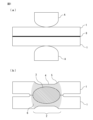
- FIG. 2 is a diagram illustrating a welded joint according to the present invention.
- FIG. 2 is a diagram showing a layer formed around the weld of the welded joint of the present invention.
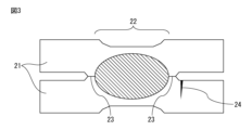
- FIG. 1 is a diagram illustrating an evaluation of LME resistance in an example.
- the plating melts and the surface layer of the steel sheet is heated, transforming the steel sheet structure to austenite.
- the hot-dip plating penetrates into the steel sheet structure along the austenite grain boundaries, embrittling the grain boundaries.
- LME cracking is likely to occur at the grain boundaries.
- tensile stress is applied to the steel sheet during welding, making LME cracking more likely to occur.
- the welded joint of the present invention improves the LME resistance during the manufacture of the welded joint due to the structure formed in the surface layer of the steel sheet that constitutes the welded joint.
- the surface layer of the steel sheet refers to the range from the outermost surface of the steel sheet to a depth of 100 ⁇ m.
- the steel sheet that constitutes the welded joint of the present invention has a region 3 ⁇ m or more from the surface of the steel sheet in the depth direction from the surface of the steel sheet where the carbon concentration measured by GDS is 0.01% or less. This means that the carbon concentration in the surface layer of the steel sheet is low.
- the steel sheet constituting the welded joint of the present invention has improved LME resistance during the manufacture of the welded joint by controlling the form of C in the surface layer.
- the inventors have thus found that in order to reduce the area ratio of cementite in the surface layer, it is important to impart strong strain to the surface layer of the steel sheet and then anneal it, as well as to control the dew point during annealing.
- the present invention by imparting a predetermined surface roughness to the surface of the steel sheet and imparting strong strain to the surface layer, it is possible to promote the diffusion of oxygen into the steel sheet and reduce the C concentration in the surface layer of the steel sheet.
- the inventors have also found that by setting the C concentration and cementite area ratio in the surface layer of the steel sheet as described above, a structure with a low cementite area ratio can be maintained even when a welded joint is manufactured, and it is possible to improve LME resistance when a welded joint is manufactured, and have thus completed the present invention.
- the welded joint of the present invention is manufactured by spot welding a plurality of steel sheets 1 (two sheets in FIG. 1) using a welding electrode A.
- a plurality of steel sheets 1 are spot welded in an overlapping state.
- spot welding is performed in the area where the steel sheets overlap each other.
- the surfaces where the steel sheets overlap and contact each other are referred to as overlapping surfaces 8.
- the surface where the plated surface of one plated steel sheet contacts the surface of the other non-plated steel sheet is referred to as the "overlapping surface”.
- the surface where the plated surfaces of the respective steel sheets contact each other is referred to as the "overlapping surface”.
- the surface where the steel sheet surfaces overlap each other is referred to as the "overlapping surface”.
- Figure 1 (b) shows a welded joint in which two steel plates are welded by spot welding.
- the welded joint of the present invention comprises multiple overlapping steel plates 1, and a spot weld 2 that joins the multiple steel plates.
- the spot weld 2 has a nugget 3, an indentation 4 pressed down by the welding electrode, and a weld shoulder 5.
- the weld shoulder 5 refers to the inclined portion of the edge (periphery) of the indentation 4.
- a heat-affected zone 6 is formed, which is a portion of the unmelted steel plate where the structure, metallurgical properties, mechanical properties, etc. have changed due to the welding heat.
- the portion other than the heat-affected zone 6 is the "non-heat-affected zone.”
- the portion of the spot weld 2 that is 5 mm or more away from the outer edge of the nugget can be determined to be a non-heat-affected zone.
- the multiple steel plates constituting the welded joint of the present invention may include both plated steel plates and unplated steel plates, as described below. Furthermore, at least one of the multiple steel plates is a high-strength steel plate having a tensile strength of 780 MPa or more. If at least one of the multiple steel plates is a high-strength steel plate having a tensile strength of 780 MPa or more, the other steel plates may be steel plates having a tensile strength of less than 780 MPa or steel plates having a tensile strength of 780 MPa or more.
- high-strength steel plate refers to a steel plate that constitutes the welded joint of the present invention and has a tensile strength of 780 MPa or more.
- LME cracking occurs when molten zinc plating is present on the surface of a high-strength steel sheet during welding.
- LME cracking may occur at the position corresponding to the overlapping surface.
- one of the steel sheets is a relatively low-strength zinc-plated steel sheet that has plating at least on the overlapping surface and the other is a non-plated high-strength steel sheet
- molten zinc plating is present on the overlapping surface of the steel sheets during welding, and the molten zinc plating comes into contact with the non-plated high-strength steel sheet, so LME cracking may occur in the high-strength steel sheet.
- the welded joint of the present invention suppresses LME cracking during manufacturing even in such cases, it may also include a welded joint in which one of the steel sheets is a relatively low-strength zinc-plated steel sheet (however, it has plating at least on the overlapping surface) and the other is a non-plated high-strength steel sheet.
- the welded joint of the present invention may include a welded joint in which one side is made of a relatively low-strength uncoated steel plate and the other side is made of a high-strength steel plate with zinc plating, or a welded joint in which one side is made of a relatively low-strength galvanized steel plate and the other side is made of a high-strength steel plate with zinc plating, or a welded joint in which both sides are made of high-strength steel plates with zinc plating.
- At least one of the pair of adjacent steel plates among the multiple steel plates may have a plating layer containing Zn at least at one of the pair of steel plates, and at least one of the pair of steel plates may be a high-strength steel plate having a tensile strength of 780 MPa or more.
- At least one of the multiple steel plates constituting a welded joint is a high-strength steel plate and the high-strength steel plate is located on the outermost side of the multiple steel plates constituting the welded joint (at a position where the welding electrode can come into direct contact with the plate during spot welding), LME cracking may occur during spot welding even if all the steel plates constituting the welded joint are non-plated steel plates.
- the molten zinc plating may adhere to the welding electrode. If such a welding electrode is used, the plating adhered to the welding electrode may melt during spot welding and adhere to the high-strength steel plate that is not plated.
- the welded joint of the present invention can also suppress such LME cracking during the production of the welded joint, even if all the steel plates constituting the welded joint are non-plated steel plates.
- the present invention suppresses LME occurring in high-strength steel plates during the manufacture of a welded joint.
- At least one of the steel plates constituting the welded joint according to the present invention is a high-strength steel plate.
- the high-strength steel plate is a steel plate having a tensile strength of 780 MPa or more.
- the upper limit of the tensile strength is not particularly limited, but may be, for example, 2000 MPa or less from the viewpoint of ensuring toughness.
- the tensile strength may be measured in accordance with JIS Z 2241:2011 by taking a JIS No.
- the tensile strength may be 880 MPa or more, 980 MPa or more, 1080 MPa or more, or 1180 MPa or more.
- the tensile strength may be 1900 MPa or less, or 1800 MPa or less.
- the following method is adopted, for example, to identify the rolling direction of the steel plate.
- the S concentration is measured using an electron probe microanalyzer (EPMA).
- the measurement conditions are an acceleration voltage of 15 kV and a measurement pitch of 1 ⁇ m, and a distribution image is measured in a 500 ⁇ m square range in the center of the plate thickness.
- the extended area with a high S concentration is determined to be an inclusion such as MnS.
- observation may be performed in multiple fields of view.
- a surface parallel to the surface rotated in 5° increments in the range of 0° to 180° around the plate thickness direction is observed by the above method.
- the average value of the long axis length of the multiple inclusions in each obtained cross section is calculated for each cross section, and the cross section with the largest average long axis length of the inclusions is identified.
- the direction parallel to the longitudinal axis of the inclusions in the cross section is determined to be the rolling direction.
- the hardness (Vickers hardness) of the steel plate in the non-heat-affected zone which is 5 mm or more away from the outer edge of the spot weld, can be measured as an alternative, and the tensile strength value can be estimated from the following correlation formula (Correlation Between Static Strength Parameters, Hasegawa Norihiko, Arai Junichi, Tanaka Michishichi, "Zairyo" Vol. 39 No. 442, pp. 859-863).
- “heat-affected zone” refers to the part of the steel plate that has not melted and where the structure, metallurgical properties, mechanical properties, etc.
- non-heat-affected zone refers to the part other than the heat-affected zone.
- the part that is 5 mm or more away from the outer edge of the spot weld can be determined to be the non-heat-affected zone.
- Hv 0.301 ⁇ TS+5.701 (Here, Hv is Vickers hardness and TS is tensile strength (unit: MPa).) In other words, if the hardness is about 240 Hv or more, it can be considered that the tensile strength is 780 MPa or more.
- the hardness of the steel plate is measured at a 1/2 depth position in the non-heat-affected zone of the steel plate constituting the welded joint. Hardness measurements are performed in accordance with JIS Z 2244:2009. The measurement load is 200 gf.
- the hardness of the high-strength steel plate in the non-heat-affected zone located 5 mm or more away from the outer end of the spot weld may be 245 Hv or more, 250 Hv or more, 260 Hv or more, 270 Hv or more, 300 Hv or more, or 340 Hv or more.
- C (C: 0.08-0.40%) C (carbon) is an element that ensures the strength of steel.
- the C content is set to 0.08% while taking into consideration the balance with weldability.
- the C content may be 0.10% or more, 0.12% or more, or 0.15% or more.
- the C content may be 0.40% or less, 0.35% or less. % or less, and may be 0.30% or less.
- Silicon (Si) is an element that promotes ferrite stabilization and decarburization. By including silicon, decarburization progresses in the surface layer and the ferrite in the surface layer is stabilized by the pretreatment and heat treatment described below. In order to obtain this effect, the Si content is set to 0.4 to 2.0%. The Si content is set to 0.5% or more, and 0.6% or less. % or more, 0.7% or more, or 0.8% or more. The Si content may be 1.8% or less, 1.7% or less, 1.6% or less, or 1.5% or less. It may be.
- Al (aluminum) is an element that, like Si, promotes ferrite stabilization and decarburization by dissolving in steel.
- Sol . Al is not in the form of oxides such as Al2O3 .
- the term "acid-soluble Al” refers to Al that is soluble in acid, and is determined as the amount of Al measured after excluding the insoluble residue on the filter paper that is generated during the analysis of Al.
- the role of Al can be achieved by including Si, so Al is not essential, and the lower limit of the content of sol. Al is 0%.
- the content of sol. Al may be 0.1% or more, 0.2% or more, or 0.3% or more.
- the content of sol. Al is 1.5 % or less, 1.2% or less, or 1.0% or less.
- the total content of Si and sol. Al is less than 1.8%.
- the total content of Si and sol. Al may be less than 1.7%, or less than 1.6%.
- Mn manganese
- Mn manganese
- Mn is an effective element for improving the strength of steel by obtaining a hard structure. Taking into consideration the balance between the strength of steel and the decrease in workability due to Mn segregation, the Mn content is 0.1 to 5.0%. The Mn content may be 0.5% or more, 1.0% or more, or 1.5% or more. The Mn content is 4.5% It may be 4.0% or less, or 3.5% or less.
- P 0.0300% or less
- P (phosphorus) is an impurity generally contained in steel. If the P content exceeds 0.0300%, there is a risk of reduced weldability. Therefore, the P content is set to 0.0300% or less.
- the P content may be 0.0200% or less, 0.0100% or less, or 0.0050% or less. It is preferable that no P is contained, and the lower limit of the P content is 0%. From the viewpoint of phosphorus cost, the P content may be more than 0%, 0.0001% or more, or 0.0005% or more.
- S sulfur
- S is an impurity generally contained in steel. If the S content exceeds 0.0300%, the weldability decreases, and further, the amount of precipitated MnS increases, which deteriorates workability such as bendability. Therefore, the S content is set to 0.0300% or less.
- the S content may be 0.0100% or less, 0.0050% or less, or 0.0020% or less. It is preferable that no S is contained, and the lower limit of the S content is 0%. From the viewpoint of desulfurization costs, the S content may be more than 0%, 0.0001% or more, or 0.0005% or more. .
- N nitrogen
- nitrogen is an impurity generally contained in steel. If the N content exceeds 0.0100%, there is a risk of reduced weldability. Therefore, the N content is set to 0.0100% or less.
- the N content may be 0.0080% or less, 0.0050% or less, or 0.0030% or less. It is preferable that N is not contained, and the lower limit of the N content is 0%. From the viewpoint of cost, the N content may be more than 0%, 0.0001% or more, 0.0005% or more, or 0.0010% or more.
- B (boron) is an element that improves hardenability, contributes to improving strength, and segregates at grain boundaries to strengthen the grain boundaries and improve toughness, so it may be contained as necessary. Since B is not an essential element, the lower limit of the B content is 0%. This effect can be obtained even with a small amount of B, but if B is contained, the B content is preferably 0.0001% or more. The content of B may be 0.0002% or more, or 0.0003% or more. On the other hand, from the viewpoint of ensuring sufficient toughness, the content of B is set to 0.0100% or less. The amount may be 0.0080% or less, 0.0060% or less, 0.0040% or less, or 0.0020% or less.
- Ti titanium
- Ti titanium
- Ti titanium
- the Ti content is 0%. This effect can be obtained even with a small amount of Ti, but when Ti is contained, the Ti content is preferably 0.0001% or more. The Ti content is 0.0003% or more.
- the Ti content is set to 0.1500% or less. may be 0.1000% or less, 0.0500% or less, 0.0050% or less, or 0.0020% or less.
- Niobium (Nb) is an element that contributes to improving strength by improving hardenability, and may be contained as necessary. Since it is not an essential element, the lower limit of the Nb content is 0%. This effect can be obtained even with a small amount of Nb, but when Nb is contained, the Nb content is preferably 0.002% or more. The Nb content is preferably 0.005% or more, or 0.010% or more. On the other hand, from the viewpoint of ensuring sufficient toughness, the Nb content is set to 0.150% or less. The Nb content is set to 0.100% or less, 0.060% or less, 0.040% or less. It may be 0.020% or less, or 0.020% or less.
- V Vanadium
- V is an element that contributes to improving strength by improving hardenability, and therefore may be contained as necessary. Since it is not an essential element, the lower limit of the V content is 0%. This effect can be obtained even with a small amount of V, but when V is contained, the V content is preferably 0.003% or more. On the other hand, from the viewpoint of ensuring sufficient toughness, the V content is set to 0.150% or less. The V content is set to 0.100% or less, 0.060% or less, or 0.020% or less. % or less.
- Cr 0-2.00% Cr (chromium) is effective in increasing the hardenability of steel and increasing the strength of steel, so it may be contained as necessary. Since it is not an essential element, the lower limit of the Cr content is 0%. This effect can be obtained even with a small amount of Cr, but when Cr is contained, the Cr content is preferably 0.01% or more. The Cr content is preferably 0.05% or more, or 0. 10% or more. On the other hand, if it is contained in excess, a large amount of Cr carbide is formed, which may adversely impair hardenability, so the Cr content is set to 2.00% or less. The content may be less than or equal to 1.80%, less than or equal to 1.50%, less than or equal to 0.50%, or less than or equal to 0.20%.
- Ni 0-2.00%
- Ni nickel
- the lower limit of the Ni content is This effect can be obtained even with a small amount of Ni contained, but when Ni is contained, the Ni content is preferably 0.001% or more, more preferably 0.02% or more, and further preferably 0.05% or more.
- the Ni content is set to 2.00% or less, preferably 1.80% or less, more preferably 1.50% or less, and further preferably 0. 50% or less, 0.20% or less.
- Cu (copper) is effective in increasing the hardenability of steel and increasing the strength of steel, so it may be contained as necessary. Since it is not an essential element, the lower limit of the Cu content is This effect can be obtained even with a small amount of Cu, but when Cu is contained, the Cu content is preferably 0.0001% or more. On the other hand, from the viewpoint of suppressing deterioration of toughness, cracking of the slab after casting, and deterioration of weldability, the Cu content is set to 2.0000% or less. .8000% or less, 1.5000% or less, 0.0050% or less, or 0.0020% or less.
- Mo mobdenum
- Mo mobdenum
- the Mo content is set to 1.00% or less.
- the Mo content is set to 0.80% or less, 0.60% or less, Or it may be 0.20% or less.
- W 0-1.000%) W (tungsten) is effective in increasing the hardenability of steel and increasing the strength of steel, so it may be contained as necessary. Since it is not an essential element, the lower limit of the W content is This effect can be obtained even with a small amount of W, but when W is contained, the W content is preferably 0.001% or more. The W content is preferably 0.002% or more, or 0. On the other hand, from the viewpoint of suppressing a decrease in toughness, the W content is set to 1.000% or less. The W content is set to 0.800% or less, 0.600% or less , 0.300% or less, 0.100% or less, or 0.020% or less.
- Ca (Ca: 0-0.1000%)
- Ca (calcium) is an element that contributes to inclusion control, particularly to finely dispersing inclusions, and has the effect of increasing toughness, so it may be contained as necessary. Since it is not an essential element, Ca The lower limit of the Ca content is 0%. This effect can be obtained even with a small amount of Ca included, but when Ca is included, the Ca content is preferably 0.0001% or more. The Ca content may be 0.0002% or more, or 0.0003% or more. On the other hand, if the Ca content is excessive, deterioration of the surface properties may become apparent, so the Ca content is set to 0.1000% or less. The amount may be 0.0800% or less, 0.0500% or less, 0.0300% or less, 0.0100% or less, or 0.0010% or less.
- Mg manganesium
- Mg is an element that contributes to inclusion control, particularly to finely dispersing inclusions, and has the effect of increasing toughness, so it may be contained as necessary. Since it is not an essential element, Mg The lower limit of the Mg content is 0%. This effect can be obtained even with a small amount of Mg, but when Mg is contained, the Mg content is preferably 0.0001% or more. The Mg content may be 0.0005% or more, or 0.0008% or more. On the other hand, if the Mg content is excessive, deterioration of the surface properties may become evident, so the Mg content is set to 0.100% or less. The amount may be 0.090% or less, 0.080% or less, 0.030% or less, 0.010% or less, or 0.002% or less.
- Zr zirconium
- Zr zirconium
- the lower limit of the Zr content is 0%. This effect can be obtained even with a small amount of Zr, but when Zr is contained, the Zr content is preferably 0.001% or more.
- the Zr content may be 0.005% or more, or 0.010% or more.
- the Zr content is set to 0.100% or less.
- the content may be equal to or less than 0.050%, or equal to or less than 0.030%.
- Hf (hafnium) is an element that contributes to inclusion control, particularly to finely dispersing inclusions, and has the effect of increasing toughness, so it may be contained as necessary.
- the lower limit of the Hf content is 0%. This effect can be obtained even with a small amount of Hf content, but when Hf is contained, the Hf content is preferably 0.0001% or more.
- the Hf content may be 0.0003% or more, or 0.0005% or more.
- the Hf content is set to 0.100% or less.
- the content may be equal to or less than 0.050%, equal to or less than 0.030%, equal to or less than 0.010%, equal to or less than 0.005%, or equal to or less than 0.002%.
- the content may be 0.0500% or less, 0.0300% or less, 0.0100% or less, 0.0050% or less, or 0.0020% or less.
- REM is an abbreviation for Rare Earth Metal. REM refers to elements that belong to the lanthanide series. REM are usually added as misch metals.
- the remainder other than the above chemical components consists of Fe and impurities.
- impurities refer to components that are mixed in due to various factors in the manufacturing process, including raw materials such as ores and scraps, when the steel plate is industrially manufactured, and that do not adversely affect LME cracking during the manufacturing of the welded joint according to the present invention.
- Analysis of the chemical components of steel plate may be performed using elemental analysis methods known to those skilled in the art, for example, inductively coupled plasma mass spectrometry (ICP-MS). However, C and S may be measured using the combustion-infrared absorption method, and N may be measured using the inert gas fusion-thermal conductivity method. These analyses may be performed on samples taken from the steel plate using methods in accordance with JIS G0417:1999.
- ICP-MS inductively coupled plasma mass spectrometry
- the depth at which the C concentration measured by GDS (glow discharge spectroscopy) is 0.01% or less in the depth direction from the surface of the high-strength steel plate is 3 ⁇ m or more.
- Such a surface structure can be obtained by setting the chemical composition of the steel sheet as described above and carrying out the pretreatment and heat treatment described below.
- the effect of improving LME resistance can be obtained if the depth at which the C concentration is 0.01% or less is 3 ⁇ m or more, so there is no particular upper limit to the depth.
- the depth at which the C concentration is 0.01% or less may be 50 ⁇ m or less, 40 ⁇ m or less, or 30 ⁇ m or less.
- the depth at which the C concentration is 0.01% or less may be 5 ⁇ m or more, 7 ⁇ m or more, 10 ⁇ m or more, 15 ⁇ m or more, or 20 ⁇ m or more.
- the carbon concentration is measured by GDS five times in the thickness direction at different positions on the surface of the high-strength steel plate, and the average value is taken as the carbon concentration.
- the measurement conditions are as follows:
- the starting point of the "depth" for GDS measurement is the surface of the high-strength steel sheet, and if the high-strength steel sheet has a plating layer as described below, it is the interface between the steel sheet and the plating layer.
- the interface between the steel sheet and the plating layer is the position where the Fe concentration measured by GDS measurement is 93% of the Fe concentration at a depth of 150 ⁇ m.
- the roughness of the interface between the steel sheet and the plating layer is more than 3.0 ⁇ m in terms of arithmetic mean roughness Ra defined in JIS B0601:2013.
- strain is introduced while increasing the roughness of the surface of the steel sheet. This improves the LME resistance.
- the upper limit of the surface roughness is not limited, but may be 20.0 ⁇ m or less, 15.0 ⁇ m or less, or 10.0 ⁇ m or less.
- the roughness of the interface between the steel sheet and the plating layer may be the surface roughness of the steel sheet measured after removing the plating. The plating is removed by dissolving the plating layer in an acid solution to which an inhibitor that suppresses corrosion of the steel sheet has been added.
- the thickness of a layer in which the area ratio of cementite is 10% or less (hereinafter referred to as a "low cementite layer”) is 8 ⁇ m or more in the depth direction from the surface of the high-strength steel plate.
- Figure 2 shows an example of a microstructure photograph of a plated high-strength steel plate as an example of a steel plate constituting a welded joint of the present invention.
- Figure 2 is a SEM microstructure photograph taken at 1000x magnification of the surface of a plated high-strength steel plate.
- Figure 2 shows a cross section parallel to the thickness direction of the steel plate, with the upper side of the drawing being the surface of the steel plate, and the plated layer 13 and its surface are shown.
- the surface of the steel plate contains a low-cementite layer 11, which has a low C concentration, is mainly composed of ferrite 14, and has an area ratio of cementite 15 of 10% or less.
- the steel plate portion in Figure 1 is divided into areas with relatively high brightness (bright) and areas with relatively low brightness (dark), the areas with relatively high brightness can be determined to be cementite. The areas with relatively low brightness can be determined to be ferrite.
- the effect of improving LME resistance can be obtained if the low cementite layer is 8 ⁇ m or more in thickness, so there is no particular upper limit to its thickness.
- the thickness of the low cementite layer may be 50 ⁇ m or less, 40 ⁇ m or less, or 30 ⁇ m or less.
- the thickness of the low cementite layer may be 10 ⁇ m or more, or 20 ⁇ m or more.
- the structure other than the cementite in the low cementite layer is not limited.
- it can be one or more of martensite, bainite, and ferrite. Since ferrite has low LME susceptibility, a structure mainly composed of ferrite is preferable from the viewpoint of improving LME resistance.
- the thickness of the low cementite layer is determined by nital etching the C-section of the steel plate (plate thickness section parallel to the rolling direction (L-direction)) and observing a 50 ⁇ m x 50 ⁇ m field of view including the surface layer of the steel plate at 1000x magnification using an SEM. From the structural morphology on the SEM image obtained by SEM observation, it is possible to distinguish between hard structures such as martensite and bainite, which contain relatively large amounts of cementite, and ferrite. The thickness of the low cementite layer is measured in a measurement range of 500 ⁇ m in the L-direction, and the measurement range is divided into five ranges spaced 1000 ⁇ m apart in the L-direction.
- the average thickness of the low cementite layer in the plate thickness direction for the five measurement ranges is taken as the average value.
- the area ratio of cementite refers to the area ratio determined by observation on the C-section.
- the thickness of the low-cementite layer begins at the interface between the high-strength steel sheet and the plating layer.
- a plating layer containing Zn may be provided on a part or the whole of the surface of one or more of the steel plates constituting the welded joint of the present invention.
- a plating layer may be provided on the outermost surface of the overlapping steel plates, or on the surface constituting the overlapping surface.
- a plating layer may be provided on both of them.
- the plating layer is not particularly limited as long as it contains Zn.
- Examples include Zn-0.2%Al (GI), Zn-(0.3 to 1.5)%Al, Zn-4.5%Al, Zn-0.09%Al-10%Fe (GA), Zn-1.5%Al-1.5%Mg, Zn-11%Al-3%Mg-0.2%Si, Zn-11%Ni, Zn-15%Mg, Zn-20%Al-7%Mg, and Zn-30%Al-10%Mg.
- GI Zn-0.2%Al
- Zn-(0.3 to 1.5)%Al Zn-4.5%Al
- Zn-0.09%Al-10%Fe GA
- Zn-1.5%Al-1.5%Mg Zn-11%Al-3%Mg-0.2%Si
- Zn-11%Ni Zn-15%Mg
- Zn-20%Al-7%Mg Zn-30%Al-10%Mg.
- the chemical composition of the plating layer can be determined by dissolving the plating layer in an acid solution containing an inhibitor that suppresses corrosion of the steel sheet, and measuring the resulting solution using ICP (inductively coupled plasma) emission spectroscopy.
- the acid solution containing the inhibitor may be, for example, a 10% by mass hydrochloric acid solution containing 0.06% by mass inhibitor (Ibit, manufactured by Asahi Chemical Industry Co., Ltd.).
- the thickness of the plating layer may be, for example, 3 to 50 ⁇ m.
- the coating weight of the plating layer is not particularly limited, but may be, for example, 10 to 170 g/m 2 per side.
- the coating weight of the plating layer is determined by dissolving the plating layer in an acid solution to which an inhibitor that suppresses corrosion of the steel sheet is added, and measuring the weight change before and after the plating layer is peeled off by pickling.
- the thickness of the plating layer may be 5 ⁇ m or more, 10 ⁇ m or more, 15 ⁇ m or more, or 20 ⁇ m or more.
- the thickness of the plating layer may be 40 ⁇ m or less, or 30 ⁇ m or less.
- the coating weight of the plating layer may be 20 g/m 2 or more, 30 g/m 2 or more, 40 g/m 2 or more, or 50 g/m 2 or more per side.
- the coating weight of the plating layer may be 150 g/m 2 or less, 130 g/m 2 or less, 120 g/m 2 or less, or 100 g/m 2 or less per side.
- the other steel plates may be high-strength steel plates or steel plates other than high-strength steel plates.
- the tensile strength of the steel plates other than high-strength steel plates may be, for example, 390 MPa or more, 490 MPa or more, or 590 MPa or more.
- LME cracking in the outermost layer of a welded joint can occur when the steel plate of the outermost layer is a high-strength steel plate with a high C concentration and has zinc plating on the surface side, or when molten zinc plating is attached to the welding electrode.
- Examples of LME cracking in the outermost layer of a welded joint include cracks in the indentation area caused by the welding electrode (cracks directly below the welding electrode) and cracks in the inclined area (shoulder area) formed on the periphery of the indentation area (cracks in the weld shoulder area).
- plating may be applied to both steel plates constituting the overlapping surfaces, or only to one of the steel plates.
- Examples of combinations of steel plates constituting the overlapping surfaces include (1) high-strength steel plates that are both plated, (2) one high-strength steel plate that is plated and the other high-strength steel plate that is not plated, (3) one high-strength steel plate that is plated and the other steel plate other than high-strength steel plate that is plated, (4) one high-strength steel plate that is plated and the other steel plate other than high-strength steel plate that is not plated, and (5) one high-strength steel plate that is not plated and the other steel plate other than high-strength steel plate that is plated.
- LME cracking during manufacturing can be suppressed in any combination.
- the thickness of the high-strength steel plate and the steel plate other than the high-strength steel plate constituting the welded joint of the present invention is not particularly limited. For example, it can be 0.6 to 3.2 mm.
- the thickness may be 0.8 mm or more, or 1.0 mm or more.
- the thickness may be 3.0 mm or less, 2.6 mm or less, 2.4 mm or less, 2.2 mm or less, 2.0 mm or less, or 1.8 mm or less.
- the high-strength steel sheet constituting the welded joint according to the present invention can be obtained by a manufacturing method including, for example, a casting process in which molten steel with adjusted chemical composition is cast to form a steel billet, a hot rolling process in which the steel billet is hot rolled to obtain a hot rolled steel sheet, a coiling process in which the hot rolled steel sheet is coiled, a cold rolling process in which the coiled hot rolled steel sheet is cold rolled to obtain a cold rolled steel sheet, a pretreatment process in which the cold rolled steel sheet is grit blasted, and an annealing process in which the pretreated cold rolled steel sheet is annealed.
- the hot rolled steel sheet may be pickled and cold rolled as it is without being coiled after the hot rolling process.
- the conditions for the casting process are not particularly limited. For example, after melting in a blast furnace or an electric furnace, various secondary smelting processes may be carried out, and then casting may be carried out by a method such as ordinary continuous casting or casting by an ingot method.
- the steel slab obtained by casting can be hot-rolled to obtain a hot-rolled steel sheet.
- the hot rolling step is performed by reheating the cast steel slab directly or after cooling once, and then hot rolling it.
- the heating temperature of the steel slab may be, for example, 1100 to 1250°C.
- rough rolling and finish rolling are usually performed.
- the temperature and reduction rate of each rolling may be appropriately changed depending on the desired metal structure and plate thickness.
- the finishing temperature of the finish rolling may be 900 to 1050°C, and the reduction rate of the finish rolling may be 10 to 50%.
- the hot-rolled steel sheet can be coiled at a predetermined temperature.
- the coiling temperature may be appropriately changed depending on the desired metal structure, etc., and may be, for example, 500 to 800°C.
- the hot-rolled steel sheet may be subjected to a predetermined heat treatment by recoiling before or after coiling. Alternatively, the hot-rolled steel sheet may be pickled after the hot rolling process without coiling, and then cold-rolled as described below.
- the hot-rolled steel sheet After the hot-rolled steel sheet is subjected to pickling or the like, the hot-rolled steel sheet is cold-rolled to obtain a cold-rolled steel sheet.
- the rolling reduction of the cold rolling may be appropriately changed depending on the desired metal structure and sheet thickness, and may be, for example, 20 to 80%.
- the steel sheet After the cold rolling process, the steel sheet may be cooled to room temperature, for example, by air cooling.
- the pretreatment includes grit blasting the surface of the cold-rolled steel sheet using an angular abrasive.
- the abrasive that can be used is not particularly limited, but for example, polygonal steel grit having an average particle size of 100 to 500 ⁇ m, preferably 120 to 420 ⁇ m, more preferably 180 to 350 ⁇ m can be used.
- An example of such grit is TGD-30 manufactured by WINOA IKK JAPAN. This allows strain to be introduced while increasing the surface roughness.
- the amount of grit projection is preferably 5 to 400 kg/m 2.
- the amount of projection per unit time and unit area at a projection amount of 400 kg/m 2 is 4.0 ⁇ 10 ⁇ 4 kg/(mm 2 ⁇ min).
- the surface roughness of the steel sheet after the pretreatment is maintained in the steel sheet and plated steel sheet according to the present invention after the annealing step and plating step (including the alloying step) described below.
- the pretreated cold-rolled steel sheet is annealed under high dew point conditions (high dew point annealing).
- the annealing is performed under tension of 1 to 20 MPa. Applying tension during annealing makes it possible to introduce strain into the steel sheet more effectively, accelerating decarburization of the surface layer.
- the holding temperature in the annealing process is 750 to 900°C.
- the holding temperature may be 770 to 870°C. By keeping the temperature in this range, it is possible to promote decarburization, lower the C concentration in the surface layer, and reduce cementite.
- the holding time at the holding temperature in the annealing process is 40 to 300 seconds.
- the holding time may be 50 to 250 seconds.
- the atmosphere in the annealing step has a dew point of -30 to 20°C.
- the dew point may be -10 to 5°C.
- the atmosphere may be, for example, N 2 -1 to 10 vol% H 2 or N 2 -2 to 4 vol% H 2. If the dew point is too high or too low, a phase containing oxides of Si, Mn, Al, etc. is formed outside the steel sheet, and decarburization is not promoted. Furthermore, interdiffusion of the plating components and the steel components is inhibited, and plating properties may become insufficient.
- the manufacturing method including the above-mentioned steps promotes decarburization in the surface layer of the high-strength steel plate, resulting in a high-strength steel plate with reduced cementite.
- the plated steel sheet can be obtained by performing a plating process to form a plating layer containing Zn on the high-strength steel sheet produced as described above, or on any steel sheet that can form the welded joint according to the present invention.
- the plating process may be performed according to a method known to those skilled in the art.
- the plating process may be performed, for example, by hot-dip plating or by electroplating.
- the plating process is performed by hot-dip plating.
- the conditions of the plating process may be appropriately set in consideration of the chemical components, thickness, and coating weight of the desired plating layer.
- the steel may be immersed in a hot-dip galvanizing bath at 420 to 480°C with adjusted chemical components for 1 to 10 seconds, and after immersion, the steel may be pulled out at 20 to 200 mm/second, and the coating weight may be controlled by N2 wiping gas.
- an alloying process may be performed to obtain alloyed plating.
- the alloying process may be performed, for example, at 500 to 550°C for 10 to 60 seconds.
- the above-mentioned steel plate and high-strength steel plate are overlapped and spot-welded to obtain a welded joint.
- the steel plate may be overlapped in a plurality of sheets.
- the high-strength steel plate may be overlapped at any position (in the lamination direction or in the plate thickness direction) as long as it can exhibit LME resistance.
- the conditions of the spot welding are not particularly limited. For example, spot welding can be performed using a dome radius type welding electrode with a tip diameter of 8 mm, with a pressure of 4.0 kN, a current flow time of 0.5 seconds, and a current flow current of 12 kA.
- the welded joint of the present invention is suitable for use in a wide range of fields, including automobiles, home appliances, and building materials, because LME cracking during manufacturing is suppressed. It is particularly suitable for use in the automobile field.
- Example No. 1 Molten steel adjusted to the chemical composition shown in No. 1 of Table 1 was melted in a blast furnace and cast by continuous casting to obtain a steel slab.
- the obtained steel slab was heated to 1200°C and hot-rolled with a finish rolling end temperature of 950°C and a finish rolling reduction of 30% to obtain a hot-rolled steel sheet.
- the obtained hot-rolled steel sheet was coiled at a coiling temperature of 650°C, pickled, and then cold-rolled with a reduction of 50% to obtain a cold-rolled steel sheet.
- the cold-rolled steel sheet had a thickness of 1.6 mm.
- the surface roughness of the steel plate was measured in accordance with JIS B 0601:2013. That is, 10 locations were randomly selected on the surface of the steel plate, and the surface profile at each location was measured using a contact surface roughness meter. The arithmetic mean roughness Ra obtained by averaging the surface roughness at these locations was evaluated as follows:
- Grade AA More than 4.0 ⁇ m Grade A: More than 3.0 ⁇ m, 4.0 ⁇ m or less Grade B: 3.0 ⁇ m or less
- annealing was performed in a furnace with an oxygen concentration of 20 ppm or less, in an N 2 -4% H 2 gas atmosphere, with a dew point of 0° C., a holding temperature of 800° C., and a holding time of 40 seconds.
- the heating rate during annealing was 6.0° C./sec up to 500° C., and 2.0° C./sec from 500° C. to the holding temperature.
- the annealing was performed under a tension of 5.0 MPa.
- the steel sheet was subjected to a plating treatment and further to an alloying treatment to obtain a galvannealed steel sheet (a high-strength steel sheet having an alloyed hot-dip galvannealed coating).
- the plating treatment was performed by immersing the steel sheet in a 450°C hot-dip galvanizing bath (Zn-0.14%Al) for 3 seconds. After immersion, the steel sheet was pulled out at 100 mm/sec, and the coating weight was controlled to 50 g/ m2 by N2 wiping gas, followed by an alloying treatment at 520°C for 30 seconds.
- Examples 2 to 28, Comparative Examples 29 to 40> Welded joints were produced in the same manner as in Example 1, except that the chemical compositions were those shown in Table 1, the conditions for the pretreatment process and the annealing process were those shown in Table 2, and the plating type was those shown in Table 3, and the LME resistance during production was evaluated. Note that, in No. 36, grit blasting was not performed, and in No. 40, surface treatment was performed by grinding with a brush instead of grit blasting.
- Grade AAA 1180 MPa or more Grade AA: 980 MPa or more, less than 1180 MPa Grade A: 780 MPa or more, less than 980 MPa Grade B: Less than 780 MPa
- LME resistance With reference to FIG. 3, the evaluation of LME resistance will be described.
- the LME resistance was evaluated by the length of an LME crack (crack 24 directly outside the pressure welded portion) that occurred directly outside the pressure welded portion 23 of the spot welded portion 22 formed by overlapping two steel plates 21 and spot welding (hereinafter referred to as "directly outside the pressure welded portion").
- the directly outside the pressure welded portion of the welded portion refers to the outer part of the part (pressed portion) pressed by spot welding on the overlapping surface of the two steel plates, and refers to a position in the vicinity of the pressure welded portion (within a range of about 1 mm from the end of the pressure welded portion to the outside).
- the length of the crack 24 directly outside the pressure welded portion was evaluated.
- evaluation criteria were as follows. In this example, if the evaluation was A or higher (i.e., evaluation A, AA, AAA), it was determined that the LME resistance was excellent. Note that the test by spot welding was performed multiple times until the crack 24 directly outside the pressure welded portion occurred three or more times, and the crack 24 directly outside the pressure welded portion with the longest length was evaluated.
- Grade AA More than 0 ⁇ m, less than 60 ⁇ m Grade A: 60 ⁇ m or more, less than 120 ⁇ m Grade B: 120 ⁇ m or more
- No. 29 is a comparative example in which the steel sheet has a high C content. It is believed that because the steel sheet has a high C content, the C concentration in the surface layer of the steel sheet did not decrease even when high dew point annealing was performed. As a result, the depth at which the C concentration in the non-heat-affected zone is 0.01% or less and the thickness of the layer in the heat-affected zone where the cementite area ratio is 10% or less became smaller. In addition, the roughness of the steel sheet/plating interface became smaller. As a result, the LME resistance during the production of welded joints became inferior.
- No. 30 is a comparative example in which the steel sheet has a low Si content. It is believed that because the steel sheet had a low Si content, decarburization did not progress in the surface layer even when high dew point annealing was performed. As a result, the depth at which the C concentration in the non-heat-affected zone was 0.01% or less and the thickness of the layer in the heat-affected zone where the cementite area ratio was 10% or less were reduced. In addition, the roughness of the steel sheet/plating interface was reduced. This resulted in inferior LME resistance when manufacturing welded joints.
- No. 31 is a comparative example in which the steel sheet has a high Si content. Because the steel sheet had a high Si content, even when high dew point annealing was performed, external oxidation progressed, and oxides (scale) formed on the surface layer of the steel sheet, which is thought to have suppressed decarburization at the outermost surface. As a result, the depth at which the C concentration in the non-heat-affected zone was 0.01% or less and the thickness of the layer in the heat-affected zone where the cementite area ratio was 10% or less were reduced. In addition, the roughness of the steel sheet/plating interface was reduced. As a result, the LME resistance was inferior when manufacturing the welded joint.
- No. 32 is a comparative example in which the steel sheet has a high sol. Al content. Because the steel sheet had a high sol. Al content, it is believed that even when high dew point annealing was performed, external oxidation progressed, oxides (scale) formed on the surface layer of the steel sheet, and decarburization on the outermost surface was suppressed. As a result, the thickness of the layer in the heat-affected zone where the cementite area ratio was 10% or less became smaller. In addition, the roughness of the steel sheet/plating interface became smaller. As a result, the LME resistance during the production of welded joints was inferior.
- No. 33 was held at a low temperature during annealing, which is thought to be why decarburization was not sufficiently promoted during annealing.
- the thickness of the layer in the heat-affected zone where the cementite area ratio was 10% or less was small.
- the roughness of the steel sheet/plating interface was small.
- the LME resistance was poor when manufacturing the welded joint.
- No. 34 was held at a high temperature during annealing, which is thought to have prevented sufficient decarburization during annealing. As a result, the depth of the non-heat-affected zone where the C concentration was 0.01% or less was reduced. In addition, the roughness of the steel sheet/plating interface was reduced. This resulted in poor LME resistance when manufacturing the welded joint.
- No. 35 had a short holding time during annealing, which is thought to be why decarburization was not sufficiently promoted during annealing.
- the depth where the C concentration in the non-heat-affected zone was 0.01% or less and the thickness of the layer where the cementite area ratio in the heat-affected zone was 10% or less were smaller.
- the roughness of the steel sheet/plating interface was smaller. This resulted in inferior LME resistance when manufacturing the welded joint.
- No. 36 is a comparative example in which grit blasting was not performed in the pretreatment process. It is believed that because grit blasting was not performed, no strain was introduced into the surface of the steel sheet, and decarburization did not progress during annealing. As a result, the depth where the C concentration in the non-heat-affected zone was 0.01% or less and the thickness of the layer where the cementite area ratio in the heat-affected zone was 10% or less became smaller. In addition, the roughness of the steel sheet/plating interface became smaller. This resulted in inferior LME resistance when manufacturing the welded joint.
- No. 37 is a comparative example in which the amount of grit blasting used in the grit blasting process was large. As a result, it is believed that the roughness of the steel sheet/coating interface was reduced, decarburization progressed too much, and the tensile strength of the steel sheet was reduced. In addition, the LME resistance during the production of the welded joint was also reduced.
- No. 38 had a low dew point during annealing, which is thought to have led to the formation of a phase containing oxides of Si, Mn, Al, etc. on the outside of the steel sheet, preventing decarburization.
- the depth at which the C concentration in the non-heat-affected zone was 0.01% or less and the thickness of the layer in the heat-affected zone where the cementite area ratio was 10% or less were reduced.
- the roughness of the steel sheet/plating interface was reduced. This resulted in poor LME resistance when manufacturing the welded joint.
- No. 39 had a high dew point during annealing, which is thought to have led to the formation of a phase containing oxides of Si, Mn, Al, etc. on the outside of the steel sheet, preventing decarburization.
- the depth at which the C concentration in the non-heat-affected zone was 0.01% or less and the thickness of the layer in the heat-affected zone where the cementite area ratio was 10% or less were reduced.
- the roughness of the steel sheet/plating interface was reduced. This resulted in poor LME resistance when manufacturing the welded joint.
- No. 40 is a comparative example in which surface treatment was performed by grinding with a brush instead of grit blasting. It is believed that grinding with a brush did not introduce sufficient strain into the surface of the steel sheet, and decarburization did not progress during annealing. As a result, the depth where the C concentration in the non-heat-affected zone was 0.01% or less and the thickness of the layer where the cementite area ratio in the heat-affected zone was 10% or less became smaller. In addition, the roughness of the steel sheet/plating interface became smaller. This resulted in inferior LME resistance when manufacturing the welded joint.
- Nos. 1 to 28 are examples of the present invention, and had high LME resistance. It was confirmed that examples in which the depth of the non-heat-affected zone where the C concentration was 0.01% or less and the thickness of the layer in the heat-affected zone where the cementite area ratio was 10% or less were large had particularly excellent LME resistance during the production of welded joints.
- the present invention makes it possible to provide high-strength steel sheets and plated steel sheets with high LME resistance, and the steel sheets and plated steel sheets can be suitably used for automobiles, home appliances, building materials, and the like, particularly for automobiles. Therefore, the present invention has extremely high industrial applicability.
Landscapes
- Chemical & Material Sciences (AREA)
- Engineering & Computer Science (AREA)
- Mechanical Engineering (AREA)
- Materials Engineering (AREA)
- Metallurgy (AREA)
- Organic Chemistry (AREA)
- Physics & Mathematics (AREA)
- Thermal Sciences (AREA)
- Crystallography & Structural Chemistry (AREA)
- Heat Treatment Of Sheet Steel (AREA)
- Butt Welding And Welding Of Specific Article (AREA)
- Arc Welding In General (AREA)
Priority Applications (5)
| Application Number | Priority Date | Filing Date | Title |
|---|---|---|---|
| KR1020257023288A KR20250121104A (ko) | 2023-01-13 | 2024-01-12 | 용접 조인트 |
| EP24741592.0A EP4650478A1 (en) | 2023-01-13 | 2024-01-12 | Welded joint |
| JP2024570235A JPWO2024150820A1 (https=) | 2023-01-13 | 2024-01-12 | |
| CN202480007562.0A CN120548378A (zh) | 2023-01-13 | 2024-01-12 | 焊接接头 |
| MX2025008113A MX2025008113A (es) | 2023-01-13 | 2025-07-10 | Union soldada |
Applications Claiming Priority (2)
| Application Number | Priority Date | Filing Date | Title |
|---|---|---|---|
| JP2023-003838 | 2023-01-13 | ||
| JP2023003838 | 2023-01-13 |
Publications (1)
| Publication Number | Publication Date |
|---|---|
| WO2024150820A1 true WO2024150820A1 (ja) | 2024-07-18 |
Family
ID=91897038
Family Applications (1)
| Application Number | Title | Priority Date | Filing Date |
|---|---|---|---|
| PCT/JP2024/000631 Ceased WO2024150820A1 (ja) | 2023-01-13 | 2024-01-12 | 溶接継手 |
Country Status (6)
| Country | Link |
|---|---|
| EP (1) | EP4650478A1 (https=) |
| JP (1) | JPWO2024150820A1 (https=) |
| KR (1) | KR20250121104A (https=) |
| CN (1) | CN120548378A (https=) |
| MX (1) | MX2025008113A (https=) |
| WO (1) | WO2024150820A1 (https=) |
Cited By (1)
| Publication number | Priority date | Publication date | Assignee | Title |
|---|---|---|---|---|
| WO2025018310A1 (ja) * | 2023-07-18 | 2025-01-23 | 日本製鉄株式会社 | 溶接継手及び自動車部材の接合構造 |
Citations (11)
| Publication number | Priority date | Publication date | Assignee | Title |
|---|---|---|---|---|
| JP2002003948A (ja) * | 2000-06-27 | 2002-01-09 | Sony Corp | 耐高温クリープ性に優れたテンションマスク用鋼板の製造方法 |
| JP2010043323A (ja) * | 2008-08-12 | 2010-02-25 | Sumitomo Metal Ind Ltd | 熱間プレス用熱延鋼板およびその製造方法ならびに熱間プレス鋼板部材の製造方法 |
| JP2017002384A (ja) * | 2015-06-15 | 2017-01-05 | 新日鐵住金株式会社 | 耐スポット溶接部破断特性に優れた鋼板及びその製造方法 |
| JP2019178405A (ja) * | 2018-03-30 | 2019-10-17 | Jfeスチール株式会社 | 鋼線材の製造方法 |
| WO2020129337A1 (ja) * | 2018-12-19 | 2020-06-25 | Jfeスチール株式会社 | 電縫鋼管 |
| WO2020136989A1 (ja) * | 2018-12-26 | 2020-07-02 | Jfeスチール株式会社 | 高強度溶融亜鉛めっき鋼板およびその製造方法 |
| WO2020136988A1 (ja) * | 2018-12-26 | 2020-07-02 | Jfeスチール株式会社 | 高強度溶融亜鉛めっき鋼板およびその製造方法 |
| WO2021200580A1 (ja) * | 2020-03-31 | 2021-10-07 | Jfeスチール株式会社 | 鋼板、部材及びそれらの製造方法 |
| WO2021200579A1 (ja) * | 2020-03-31 | 2021-10-07 | Jfeスチール株式会社 | 鋼板、部材及びそれらの製造方法 |
| WO2022210396A1 (ja) * | 2021-03-31 | 2022-10-06 | 日本製鉄株式会社 | 鋼板、鋼板の製造方法、および中間鋼板の製造方法 |
| WO2022239071A1 (ja) * | 2021-05-10 | 2022-11-17 | 日本製鉄株式会社 | 亜鉛系めっき鋼板 |
Family Cites Families (2)
| Publication number | Priority date | Publication date | Assignee | Title |
|---|---|---|---|---|
| EP3725904B1 (en) | 2017-12-15 | 2024-03-06 | Nippon Steel Corporation | Steel sheet, hot-dip zinc-coated steel sheet, and alloyed hot-dip zinc-coated steel sheet |
| KR102647647B1 (ko) | 2019-04-24 | 2024-03-18 | 닛폰세이테츠 가부시키가이샤 | 강판 |
-
2024
- 2024-01-12 WO PCT/JP2024/000631 patent/WO2024150820A1/ja not_active Ceased
- 2024-01-12 EP EP24741592.0A patent/EP4650478A1/en active Pending
- 2024-01-12 CN CN202480007562.0A patent/CN120548378A/zh active Pending
- 2024-01-12 KR KR1020257023288A patent/KR20250121104A/ko active Pending
- 2024-01-12 JP JP2024570235A patent/JPWO2024150820A1/ja active Pending
-
2025
- 2025-07-10 MX MX2025008113A patent/MX2025008113A/es unknown
Patent Citations (11)
| Publication number | Priority date | Publication date | Assignee | Title |
|---|---|---|---|---|
| JP2002003948A (ja) * | 2000-06-27 | 2002-01-09 | Sony Corp | 耐高温クリープ性に優れたテンションマスク用鋼板の製造方法 |
| JP2010043323A (ja) * | 2008-08-12 | 2010-02-25 | Sumitomo Metal Ind Ltd | 熱間プレス用熱延鋼板およびその製造方法ならびに熱間プレス鋼板部材の製造方法 |
| JP2017002384A (ja) * | 2015-06-15 | 2017-01-05 | 新日鐵住金株式会社 | 耐スポット溶接部破断特性に優れた鋼板及びその製造方法 |
| JP2019178405A (ja) * | 2018-03-30 | 2019-10-17 | Jfeスチール株式会社 | 鋼線材の製造方法 |
| WO2020129337A1 (ja) * | 2018-12-19 | 2020-06-25 | Jfeスチール株式会社 | 電縫鋼管 |
| WO2020136989A1 (ja) * | 2018-12-26 | 2020-07-02 | Jfeスチール株式会社 | 高強度溶融亜鉛めっき鋼板およびその製造方法 |
| WO2020136988A1 (ja) * | 2018-12-26 | 2020-07-02 | Jfeスチール株式会社 | 高強度溶融亜鉛めっき鋼板およびその製造方法 |
| WO2021200580A1 (ja) * | 2020-03-31 | 2021-10-07 | Jfeスチール株式会社 | 鋼板、部材及びそれらの製造方法 |
| WO2021200579A1 (ja) * | 2020-03-31 | 2021-10-07 | Jfeスチール株式会社 | 鋼板、部材及びそれらの製造方法 |
| WO2022210396A1 (ja) * | 2021-03-31 | 2022-10-06 | 日本製鉄株式会社 | 鋼板、鋼板の製造方法、および中間鋼板の製造方法 |
| WO2022239071A1 (ja) * | 2021-05-10 | 2022-11-17 | 日本製鉄株式会社 | 亜鉛系めっき鋼板 |
Non-Patent Citations (2)
| Title |
|---|
| FUMIHIKO HASEGAWAJUNICHI ARAITSUNESHICHI TANAKA: "Correlation Between Static Strength Parameters", MATERIALS, vol. 39, no. 442, pages 859 - 463 |
| See also references of EP4650478A1 |
Cited By (1)
| Publication number | Priority date | Publication date | Assignee | Title |
|---|---|---|---|---|
| WO2025018310A1 (ja) * | 2023-07-18 | 2025-01-23 | 日本製鉄株式会社 | 溶接継手及び自動車部材の接合構造 |
Also Published As
| Publication number | Publication date |
|---|---|
| JPWO2024150820A1 (https=) | 2024-07-18 |
| KR20250121104A (ko) | 2025-08-11 |
| EP4650478A1 (en) | 2025-11-19 |
| MX2025008113A (es) | 2025-08-01 |
| CN120548378A (zh) | 2025-08-26 |
Similar Documents
| Publication | Publication Date | Title |
|---|---|---|
| WO2024053669A1 (ja) | 溶接継手 | |
| WO2024150824A1 (ja) | 溶接継手 | |
| WO2024053663A1 (ja) | めっき鋼板 | |
| WO2024150820A1 (ja) | 溶接継手 | |
| WO2024150817A1 (ja) | 鋼板及びめっき鋼板 | |
| WO2024150822A1 (ja) | 鋼板及びめっき鋼板 | |
| JP7773119B2 (ja) | 鋼板、めっき鋼板及び自動車部材 | |
| JP7741465B2 (ja) | めっき鋼板 | |
| JP7832577B2 (ja) | 溶接継手及び自動車部材の接合構造 | |
| JP7773120B2 (ja) | 溶接継手及び自動車部材の接合構造 | |
| JP7741466B2 (ja) | 溶接継手 | |
| JP7741464B2 (ja) | 鋼板及び合金化溶融亜鉛めっき鋼板 | |
| JP7741469B2 (ja) | 鋼板及びめっき鋼板 | |
| JP7773121B2 (ja) | 鋼板、めっき鋼板及び自動車部材 | |
| US20260084230A1 (en) | Welded joint | |
| WO2024053667A1 (ja) | 鋼板及びめっき鋼板 | |
| CN121358882A (zh) | 镀覆钢板 |
Legal Events
| Date | Code | Title | Description |
|---|---|---|---|
| 121 | Ep: the epo has been informed by wipo that ep was designated in this application |
Ref document number: 24741592 Country of ref document: EP Kind code of ref document: A1 |
|
| WWE | Wipo information: entry into national phase |
Ref document number: 2024570235 Country of ref document: JP |
|
| WWE | Wipo information: entry into national phase |
Ref document number: 2501004615 Country of ref document: TH |
|
| WWE | Wipo information: entry into national phase |
Ref document number: 202517065810 Country of ref document: IN |
|
| ENP | Entry into the national phase |
Ref document number: 1020257023288 Country of ref document: KR Free format text: ST27 STATUS EVENT CODE: A-0-1-A10-A15-NAP-PA0105 (AS PROVIDED BY THE NATIONAL OFFICE) |
|
| WWE | Wipo information: entry into national phase |
Ref document number: 1020257023288 Country of ref document: KR Ref document number: 202480007562.0 Country of ref document: CN |
|
| WWP | Wipo information: published in national office |
Ref document number: 202517065810 Country of ref document: IN |
|
| WWP | Wipo information: published in national office |
Ref document number: 1020257023288 Country of ref document: KR |
|
| NENP | Non-entry into the national phase |
Ref country code: DE |
|
| WWP | Wipo information: published in national office |
Ref document number: 202480007562.0 Country of ref document: CN |
|
| WWP | Wipo information: published in national office |
Ref document number: 2024741592 Country of ref document: EP |