WO2024150459A1 - 筋繊維形成促進装置および筋繊維形成促進方法 - Google Patents
筋繊維形成促進装置および筋繊維形成促進方法 Download PDFInfo
- Publication number
- WO2024150459A1 WO2024150459A1 PCT/JP2023/030573 JP2023030573W WO2024150459A1 WO 2024150459 A1 WO2024150459 A1 WO 2024150459A1 JP 2023030573 W JP2023030573 W JP 2023030573W WO 2024150459 A1 WO2024150459 A1 WO 2024150459A1
- Authority
- WO
- WIPO (PCT)
- Prior art keywords
- coil
- vector potential
- bioreactor
- fiber formation
- muscle fiber
- Prior art date
- Legal status (The legal status is an assumption and is not a legal conclusion. Google has not performed a legal analysis and makes no representation as to the accuracy of the status listed.)
- Ceased
Links
Images







Classifications
-
- C—CHEMISTRY; METALLURGY
- C12—BIOCHEMISTRY; BEER; SPIRITS; WINE; VINEGAR; MICROBIOLOGY; ENZYMOLOGY; MUTATION OR GENETIC ENGINEERING
- C12M—APPARATUS FOR ENZYMOLOGY OR MICROBIOLOGY; APPARATUS FOR CULTURING MICROORGANISMS FOR PRODUCING BIOMASS, FOR GROWING CELLS OR FOR OBTAINING FERMENTATION OR METABOLIC PRODUCTS, i.e. BIOREACTORS OR FERMENTERS
- C12M1/00—Apparatus for enzymology or microbiology
-
- C—CHEMISTRY; METALLURGY
- C12—BIOCHEMISTRY; BEER; SPIRITS; WINE; VINEGAR; MICROBIOLOGY; ENZYMOLOGY; MUTATION OR GENETIC ENGINEERING
- C12M—APPARATUS FOR ENZYMOLOGY OR MICROBIOLOGY; APPARATUS FOR CULTURING MICROORGANISMS FOR PRODUCING BIOMASS, FOR GROWING CELLS OR FOR OBTAINING FERMENTATION OR METABOLIC PRODUCTS, i.e. BIOREACTORS OR FERMENTERS
- C12M1/00—Apparatus for enzymology or microbiology
- C12M1/42—Apparatus for the treatment of microorganisms or enzymes with electrical or wave energy, e.g. magnetism, sonic waves
-
- C—CHEMISTRY; METALLURGY
- C12—BIOCHEMISTRY; BEER; SPIRITS; WINE; VINEGAR; MICROBIOLOGY; ENZYMOLOGY; MUTATION OR GENETIC ENGINEERING
- C12N—MICROORGANISMS OR ENZYMES; COMPOSITIONS THEREOF; PROPAGATING, PRESERVING, OR MAINTAINING MICROORGANISMS; MUTATION OR GENETIC ENGINEERING; CULTURE MEDIA
- C12N5/00—Undifferentiated human, animal or plant cells, e.g. cell lines; Tissues; Cultivation or maintenance thereof; Culture media therefor
- C12N5/06—Animal cells or tissues; Human cells or tissues
Definitions
- the present invention relates to a muscle fiber formation promotion device and a muscle fiber formation promotion method.
- a vector potential generation device has been developed that generates a vector potential by passing a current through a vector potential coil that surrounds a solenoid coil (see, for example, Patent Document 3).
- a vector potential detection device has been developed that detects vector potential by utilizing the voltage induced by a time-varying vector potential (see, for example, Patent Document 4).
- electrodes In promoting muscle fiber formation by electrical stimulation as described above, electrodes must be in contact with the culture medium to apply an electrical stimulus to the medium. This means that (a) metal ions from the electrodes may leach from the electrodes into the culture medium, adversely affecting muscle fiber formation, and (b) the electrodes may corrode. If electrodes that do not cause these problems (such as platinum electrodes) are used, the cost of the electrodes will be high, which is not desirable.
- the present invention was made in consideration of the above, and aims to provide a muscle fiber formation promotion device and a muscle fiber formation promotion method that promotes muscle tissue formation through electrical stimulation while suppressing the occurrence of problems caused by electrodes used for electrical stimulation during muscle tissue formation.
- the muscle fiber formation promotion device of the present invention comprises a bioreactor having a storage space in which muscle fibers are formed in specific cells using a culture solution, a vector potential coil placed in at least one of the storage space and the outside of the bioreactor, and a power supply device that conducts current through the vector potential coil, generates a vector potential corresponding to the current in the storage space, and applies an electric field generated based on the vector potential to either or both of the specific cells and the culture solution, thereby providing an electrical stimulus to the specific cells.
- the method for promoting muscle fiber formation uses a culture medium to conduct current through a vector potential coil that is placed in at least one of the storage spaces and the outside of a bioreactor that has a storage space in which muscle fibers are formed from specific cells, generates a vector potential corresponding to the current in the storage space, and applies an electric field generated based on the vector potential to one or both of the specific cells and the culture medium, thereby providing an electrical stimulus to the specific cells.
- the present invention provides a muscle fiber formation promotion device and a muscle fiber formation promotion method that promote muscle tissue formation through electrical stimulation while suppressing the occurrence of problems caused by electrodes used for electrical stimulation during muscle tissue formation.
- FIG. 1 is a block diagram showing the configuration of a muscle fiber formation promoting device according to an embodiment of the present invention.
- FIG. 2 is a diagram showing an example of the bioreactor 10 and the vector potential coil device 1 in the first embodiment.
- FIG. 3 is a diagram showing an example of a bioreactor 10 and a vector potential coil device 1 in embodiment 2.
- FIG. 4 is a diagram showing an example of a vector potential coil device 1 in embodiment 3.
- FIG. 5 is a diagram showing an example (part) of a vector potential coil device 1 in embodiment 4.
- FIG. 6 is a diagram showing an example of a bioreactor 10 and a vector potential coil device 1 in embodiment 5.
- FIG. 7 is a top view showing an example of a vector potential coil device 1 in embodiment 6.
- FIG. 8 is a side view showing an example of a vector potential coil device 1 in embodiment 6.
- FIG. 9 is a side view showing an example of the vector potential coil device 1 in embodiment 7.
- FIG. 10 is a diagram showing an example of a bioreactor 10 and a vector potential coil device 1 in embodiment 8.
- FIG. 11 is a perspective view showing an example of a support member 31 of a vector potential coil device 1 in embodiment 9.
- FIG. 12 is a top view showing an example of a bioreactor 10 and a vector potential coil device 1 in embodiment 10.
- FIG. 13 is a top view showing an example of a bioreactor 10 and a vector potential coil device 1 in an eleventh embodiment.
- FIG. 14 is a side view showing an example of a bioreactor 10 and a vector potential coil device 1 in an eleventh embodiment.
- FIG. 15 is a perspective view showing an example of a bioreactor 10 and a vector potential coil device 1 in embodiment 12.
- FIG. 16 is a diagram for explaining the electrical connections of the VP coils 15a, 15b and the VP coils 16a, 16b in FIG.
- FIG. 17 is a side view showing an example of a bioreactor 10 and a vector potential coil device 1 in embodiment 12.
- FIG. 18 is a top view showing an example of a bioreactor 10 and a vector potential coil device 1 in embodiment 12.
- FIG. 1 is a block diagram showing the configuration of a muscle fiber formation promotion device according to an embodiment of the present invention.
- the muscle fiber formation promotion device shown in FIG. 1 includes a bioreactor 10, a vector potential coil device 1, a power supply device 2, and a controller 3.
- the bioreactor 10 is a component having a storage space in which muscle fibers are formed from specific cells using a culture solution.
- the specific cells may include, for example, one or both of pre-differentiation stem cells and post-differentiation myoblast cells, and may be contained in the culture solution or may be attached to a scaffold fixed within the storage space.
- the culture solution is a conductive liquid (for example, water containing nutrients and electrolytes).
- the bioreactor 10 is a pipe-shaped component.
- the bioreactor 10 may also be a container-shaped component, a culture tank, etc.
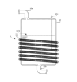
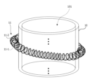
- FIG. 2 is a diagram showing an example of the bioreactor 10 and vector potential coil device 1 in embodiment 1.
- the vector potential coil device 1 includes a vector potential coil (hereinafter also referred to as a VP coil) 11 arranged in at least one of the accommodation space 101 and the outside of the bioreactor 10 (here, the outside).
- the VP coil 11 is a solenoid coil that orbits along a helical coil axis.
- the bioreactor 10 is a cylindrical member, and the VP coil 11 has a helical coil axis that orbits in a circular shape.
- the power supply device 2 also generates a current with a specific time-varying waveform (such as an AC current of a specific frequency, a pulse current, or a combination of these) based on the power of a commercial power source or a battery (primary or secondary battery), conducts that current to the VP coil 11, generates a vector potential that changes over time corresponding to that current in the above-mentioned storage space 101, and applies an electric field generated based on that vector potential to one or both of the above-mentioned specific cells and the culture solution, thereby providing an electrical stimulus to the specific cells.
- the power supply device 2 applies an AC voltage with a specific waveform such as a square wave or a sine wave to the VP coil 11, conducting the current with the above-mentioned specific waveform to the VP coil 11.
- an AC voltage V2 shown in the following equation is generated in the accommodation space 101 in response to a time change in the vector potential generated by the AC current, and an AC current corresponding to the AC voltage flows through the culture solution in the accommodation space 101.
- ⁇ 0 is the vacuum permeability
- n is the number of turns per unit length of the solenoid in the VP coil 11
- N1 is the number of turns per unit length of the helical VP coil 11
- S is the cross-sectional area of the solenoid in the VP coil 11
- ⁇ is the angular frequency of the AC current
- a is the cross-sectional radius of the helical VP coil 11
- L is the length (distance between both ends) of the VP coil 11
- t is time.
- the controller 3 is a computer or the like that executes a control program, and controls the power supply device 2 to pass a current of the specific waveform described above to the VP coil 11 at a predetermined timing (constantly, at a predetermined time interval, etc.). For example, the controller 3 may pass a pulse current of, for example, about 1 Hz to the power supply device 2.
- the controller 3 controls a fluid control device (such as a pump or valve) (not shown) to flow the culture solution containing the specific cells into the pipe-shaped bioreactor 10, and then controls the power supply device 2 to supply a current with the specific waveform to the VP coil 11. At that time, the power supply device 2 generates a current with a specific waveform (amplitude, frequency, etc.) at a specific timing and supplies it to the VP coil 11. Note that if the culture solution does not contain the specific cells, the specific cells are fixed in advance to a scaffold within the storage space 101 of the bioreactor 10.
- a fluid control device such as a pump or valve
- the current flowing through the VP coil 11 generates a magnetic field along the coil axis, and a vector potential is generated parallel to the current, with the strength of the vector potential in the inward direction of the curve of the VP coil 11 (i.e., the containing space 101) being greater than the vector potential in the outward direction of the curve of the VP coil 11 (i.e., outside the containing space 101).
- a voltage corresponding to the time change is generated as described above, and a current corresponding to the voltage is conducted to the culture solution in the storage space 101, providing an electrical stimulus to specific cells (stem cells, myoblasts, etc.) in the storage space 101.
- specific cells stem cells, myoblasts, etc.
- the controller 3 controls a fluid control device (such as a pump or valve) not shown to discharge the culture fluid from the bioreactor 10. If the culture fluid contains the specific cells described above, the specific cells are extracted from the culture fluid. In addition, the specific cells and muscle tissue that are fixed in the storage space 101 are removed from the storage space 101 of the bioreactor 10.
- a fluid control device such as a pump or valve
- the bioreactor 10 has a storage space 101 in which muscle fibers are formed in specific cells using a culture solution.
- the VP coil 11 is disposed in at least one of the storage space 101 and the outside of the bioreactor 10.
- the power supply unit 2 conducts a current through the VP coil 11, generates a vector potential corresponding to the current in the storage space 101, and applies an electric field generated based on the vector potential to one or both of the specific cells and the culture solution described above, thereby providing an electrical stimulus to the specific cells.
- FIG. 3 is a diagram showing an example of a bioreactor 10 and a vector potential coil device 1 in embodiment 2.
- the bioreactor 10 is a container-shaped member.
- the bioreactor 10 is a cylindrical container.
- the bioreactor 10 shown in FIG. 3 includes a pipe 10a for introducing the culture medium, a pipe 10b for discharging the culture medium, and a sensor 10c such as a temperature sensor.
- the bioreactor 10 may be provided with an agitation device (agitation blades, motor, etc.) as necessary.
- the culture medium is stored in the bioreactor 10, and a VP coil 11 similar to that in the first embodiment is placed outside the position (height) where the culture medium is stored.
- FIG. 4 shows an example of a vector potential coil device 1 according to embodiment 3.
- the vector potential coil device 1 includes, in addition to the VP coil 11, a ferromagnetic member 11A that extends along the coil axis within the solenoid coil that constitutes the VP coil 11.
- the ferromagnetic member 11A is made of a conductive material such as permalloy.
- One end of the VP coil 11 and one end 11A1 (first connection point) of the ferromagnetic member 11A are electrically connected to each other, and the power supply device 2 applies a voltage to the other end of the VP coil 11 and the other end 11A2 (second connection point) of the ferromagnetic member 11A, causing the VP coil 11 to conduct a current of the specific waveform described above.
- the ferromagnetic member 11A becomes the path of the above-mentioned current, and two terminals are arranged on either end side of the VP coil 11, so that the wiring from the power supply unit 2 to the VP coil 11 and the ferromagnetic member 11A can be easily laid, and the area enclosed by the path through which the wiring flows is relatively narrow, suppressing unnecessary magnetic fields generated due to the current flowing through this wiring.
- FIG. 5 shows an example (part) of a vector potential coil device 1 in embodiment 4.
- the VP coil 11 includes an inner solenoid coil 11-1 and an outer solenoid coil 11-2 that extend along the same coil axis and have different coil diameters.
- One end of the inner solenoid coil 11-1 and one end of the outer solenoid coil 11-2 are electrically connected to each other.
- the inner solenoid coil 11-1 and the outer solenoid coil 11-2 each function as a single VP coil. Therefore, the VP coil 11 in the fourth embodiment is electrically configured with two VP coils connected in series in phase.
- the power supply device 2 applies a voltage to the other end of the inner solenoid coil 11-1 and the other end of the outer solenoid coil 11-2 to conduct the above-mentioned current through the vector potential coil.
- the vector potential due to the inner solenoid coil 11-1 and the vector potential due to the outer solenoid coil 11-2 are generated in the same direction.
- FIG. 6 is a diagram showing an example of a bioreactor 10 and a vector potential coil device 1 in embodiment 5.
- a vector potential coil device 1 (VP coil 11, etc.) is placed in the accommodation space 101 of the bioreactor 10.
- an electric field generated based on the vector potential described above is applied to the culture solution described above.
- a current I(t) with the specific waveform described above will conduct circularly between the internal space of the VP coil 11 and the outside of the VP coil 11.
- a vector potential coil device 1 similar to that of embodiment 3 is placed in the accommodation space 101, but a vector potential coil device 1 similar to that of the other embodiments may also be placed in the accommodation space 101.
- the vector potential coil device 1 When the vector potential coil device 1 is placed in the accommodation space 101 of the bioreactor 10, the vector potential coil device 1 (VP coil 11 and ferromagnetic member 11A, etc.) is covered so that the conductors of the VP coil 11 (i.e., the metal parts) do not come into contact with the culture solution in the accommodation space 101. Furthermore, the power supply device 2 and controller 3 are placed outside the bioreactor 10, and the wiring from the power supply device 2 to the VP coil 11 is laid through the wall of the bioreactor 10 so as to prevent the culture solution from leaking from the bioreactor 10.
- FIG. 7 is a top view showing an example of a vector potential coil device 1 according to embodiment 6.
- FIG. 8 is a side view showing an example of a vector potential coil device 1 according to embodiment 6.
- the VP coil 12 is placed outside the accommodation space 101 of the bioreactor 10.
- the muscle fiber formation promotion device according to the sixth embodiment also includes a plurality of identical VP coils 12.
- the VP coils 12 are arranged along the axial direction of the pipe-shaped bioreactor 10.
- each VP coil 12 is a ring-shaped solenoid coil extending along the circular coil axis.
- the VP coils 12 are electrically connected to each other in series or in parallel, and generate a vector potential in the same direction at each point in time in the accommodation space 101.
- FIG. 9 is a side view showing an example of a vector potential coil device 1 in embodiment 7.
- the muscle fiber formation promotion device includes a plurality of identical VP coils 13, as shown in FIG. 9, for example.
- each VP coil 13 is an identical solenoid coil with a linear coil axis.
- the VP coils 13 are arranged along the circumferential direction of the pipe-shaped bioreactor 10.
- the power supply device 2 conducts current of the specific waveform described above to the multiple VP coils 13, generating a vector potential corresponding to the current of the specific waveform described above in the accommodation space 101, and similarly providing electrical stimulation to the specific cells described above.
- the VP coils 13 are electrically connected to each other in series or parallel, and generate vector potential in the same direction at each point in time.
- FIG. 10 is a diagram showing an example of a bioreactor 10 and a vector potential coil device 1 in embodiment 8.
- the bioreactor 10 includes a culture tank 41, a circulation pipe 42 connected to the culture tank 41 for circulating the culture fluid, and a pump 43 provided in the circulation pipe 42, and the VP coil 11 is installed in the circulation pipe 42.
- the culture fluid is circulated through the culture tank 41 and the circulation pipe 42 at a predetermined flow rate (flow rate) by the pump 43, and a vector potential is generated in the culture fluid in the circulation pipe 42 by the VP coil 11.
- the parts of the circulation pipe 42 and the pump 43 that come into contact with the culture fluid are covered with resin or a non-metallic material such as resin to prevent the culture fluid from coming into contact with metal.
- the culture fluid is electrically conductive, and electrical conductivity is ensured from the culture fluid in the inlet of pump 43 to the culture fluid in the outlet, the culture fluid is contained in culture tank 41 so that the culture fluid in culture tank 41 is at or above a predetermined reference liquid level, and the current of the specific waveform flows through culture tank 41 and the culture fluid in circulation piping 42, as well as pump 43.
- the specific cells are fixed in culture tank 41, the specific cells are electrically stimulated by the current of the specific waveform.
- the reference liquid level is set to the height of the outlet 42A of the circulation pipe 42. Even if the liquid level in the culture tank 41 is below the predetermined reference liquid level, if the culture liquid is circulating at a sufficient flow rate (flow rate), the culture liquid discharged from the outlet 42A will continue up to the liquid level in the culture tank 41, and in this case too, the current of the above-mentioned specific waveform will flow through the culture tank 41, the culture liquid in the circulation pipe 42, and the pump 43.
- the culture fluid discharged from outlet 42A falls in droplets to the liquid level of culture tank 41, in which case the current of the specific waveform described above does not flow through culture tank 41 and the culture fluid in circulation piping 42, or pump 43. Even in this case, if the culture fluid contains the specific cells described above, an electrical stimulus is given to the specific cells in circulation piping 42.
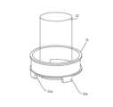
- FIG. 11 is a perspective view showing an example of a support member 31 of a vector potential coil device 1 in embodiment 9.
- the VP coils 11, 12 described above are fixed to a ring-shaped support member 31 having a larger diameter than the container-shaped bioreactor 10.
- the support member 31 has legs 31a and can stand upright.
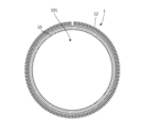
- FIG. 12 is a top view showing an example of a bioreactor 10 and a vector potential coil device 1 in embodiment 10.
- the muscle fiber formation promotion device shown in FIG. 12 includes a bioreactor 10, a VP coil 14, pipes 51 and 52, and valves 51a and 52a.
- the bioreactor 10 in the tenth embodiment has a torus shape, and the storage space also has a torus shape.
- the VP coil 14 is a single solenoid coil having a coil axis that extends in a spiral shape around the central axis of the torus shape of the bioreactor 10. Note that the VP coil 14 may also be multiple VP coils (i.e., ring-shaped solenoid coils) that each have a circular coil axis and are arranged at equal intervals in the circumferential direction.
- One of the pipes 51, 52 is a pipe for introducing culture liquid into the storage space
- the other of the pipes 51, 52 is a pipe for discharging culture liquid into the storage space.
- Valves 51a, 52a are provided on the pipes 51, 52, respectively, and are, for example, electromagnetic valves controlled by the controller 3.
- the valve 51a is opened when the culture liquid flows in and is closed otherwise
- the valve 52a is opened when the culture liquid is discharged and is closed otherwise. It is also possible to use the pipe 51 and the valve 51a for both the inflow and discharge of culture liquid without providing the pipe 52 and the valve 52a.
- the VP coil 14 generates a vector potential A oriented along the center of the spiral shape of the VP coil 14, and in the storage space, the vector potential A becomes stronger toward the inner circumference and weaker toward the outer circumference in inverse proportion to the radial distance from the center of the spiral shape.
- muscle fibers tend to grow on the inner circumference side of the storage space.
- the direction of vector potential A is circumferential, and muscle fibers tend to grow in a direction parallel to vector potential A, forming a ring shape along the storage space.
- the muscle fibers formed in a ring shape aggregate on the inner circumference side of the storage space, and excess moisture between the muscle fibers is removed, forming strong fibrous material.
- FIG. 13 is a top view showing an example of a bioreactor 10 and vector potential coil device 1 in embodiment 11.
- FIG. 14 is a side view showing an example of a bioreactor 10 and vector potential coil device 1 in embodiment 11. Note that the VP coil 14 is not shown in FIG. 14.
- the muscle fiber formation promotion device shown in Figures 13 and 14 includes a bioreactor 10, a VP coil 14, pipes 51, 52, and valves 51a, 52a, similar to embodiment 10.
- the bioreactor 10 has a spiral shape with multiple revolutions, and its storage space also has a spiral shape with multiple revolutions.
- the culture solution may be continuously flowed into the storage space via pipe 51 and continuously discharged from the storage space via pipe 52.
- the vector potential on the inner periphery of the storage space becomes stronger, and muscle fibers 201 are formed on the wall surface on the inner periphery of the bioreactor 10, as shown in FIG. 14, for example.
- the muscle fibers 201 are formed in a spiral shape along the storage space, so that by providing an opening/closing section (such as an opening/closing door) at one or both ends of the bioreactor 10 (both ends of the spiral-shaped storage space) and twisting and removing the muscle fibers 201 through the opening/closing section, it is possible to relatively easily remove continuous muscle fibers 201 from the storage space.
- an opening/closing section such as an opening/closing door
- the inside of the bioreactor 10 can be easily cleaned through the opening/closing section.
- FIG. 15 is a perspective view showing an example of a bioreactor 10 and a vector potential coil device 1 in embodiment 12.
- FIG. 16 is a diagram explaining the electrical connections of the VP coils 15a, 15b and VP coils 16a, 16b in FIG. 15.
- the bioreactor 10 includes an outer cylinder 10e and an inner cylinder 10f, and the space between the outer cylinder 10e and the inner cylinder 10f serves as a housing space 10g.
- a plurality of VP coils are provided, each of which is a solenoid coil with a linear coil axis.
- the plurality of VP coils include a first coil group (VP coils 15a, 15b) and a second coil group (VP coils 16a, 16b).
- the first coil group is arranged outside the outer cylinder 10e along the circumferential direction of the outer cylinder 10e
- the second coil group is arranged inside the inner cylinder 10f along the circumferential direction of the inner cylinder 10f.
- two adjacent VP coils 15a and 15b in the plurality of VP coils are wound in opposite directions, and one of the two ends of one VP coil 15a of the two VP coils 15a and 15b is electrically connected to the end of the other VP coil 15b of the two VP coils 15a and 15b that is closer to the one end of the one VP coil 15a.
- the VP coils 15a and 15b are connected in series.
- the VP coils 16a and 16b of the second coil group are also electrically connected in the same manner.
- the VP coils 15a and 15b generate vector potentials in the same direction
- the VP coils 16a and 16b generate vector potentials in the same direction.
- the vector potential generated by the VP coils 15a and 15b and the vector potential generated by the VP coils 16a and 16b are in the same direction.
- muscle fibers 201 are formed on the surface of the inner cylinder 10f (i.e., the inner wall surface of the storage space 10g) for the same reasons as in embodiments 10 and 11.
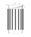
- FIG. 17 is a side view showing an example of a bioreactor 10 and vector potential coil device 1 in embodiment 12.
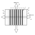
- FIG. 18 is a top view showing an example of a bioreactor 10 and vector potential coil device 1 in embodiment 12.
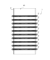
- the bioreactor 10 includes a first member 61 and a second member 62.
- the first member 61 has a plurality of flat plate portions 61a parallel to each other.
- the second member 62 has a plurality of flat plate portions 62a parallel to each other.
- the first member 61 and the second member 62 each include a support portion 61b, 62b that separates the plurality of flat plate portions 61a, 62a, and can be attached and detached by moving in a direction parallel to the plurality of flat plate portions 61a, 62a.
- the plurality of flat plate portions 61a, 62a extend vertically from the support portions 61b, 62b, respectively.
- first member 61 and the second member 62 are arranged so that the support portions 61b and 62b are parallel to each other.
- the number of flat plate portions 61a and the number of flat plate portions 62a are not particularly limited, and may be three or four or more.
- each VP coil 71 is a solenoid coil with a straight coil axis, and is arranged so that the coil axis is parallel to the support portions 61b, 62b. Note that, here, two adjacent VP coils 71 are wound alternately in opposite directions, similar to the above-mentioned VP coils 15a, 15b and VP coils 16a, 16b, and are electrically connected in the same manner.
- the first member 61 and the second member 62 are arranged such that the flat plate portion 61a of the first member 61 and the flat plate portion 62a of the second member 62 face each other but are spaced apart, and the space between the flat plate portion 61a of the first member 61 and the flat plate portion 62a of the second member 62 serves as the above-mentioned accommodation space 72.
- a vector potential A is generated in a direction perpendicular to the coil axis of the VP coil 71.
- the culture fluid may flow into and out of the storage space 72 in a direction 81 parallel to the supports 61b, 62b, as shown in FIG. 18, or may flow into and out of the storage space 72 in a serpentine manner in a direction 82 perpendicular to the supports 61b, 62b.
- the muscle fibers 201 formed on the flat plate portions 61 and 62a are exposed and can be easily harvested.
- the bioreactor 10 may be a non-metallic (e.g., resin) member or a metallic member. If the bioreactor 10 is made of metal, for example, the portions (inner walls, etc.) that come into contact with the above-mentioned culture fluid are covered with resin or the like to prevent the above-mentioned culture fluid from coming into contact with the metal.
- a non-metallic (e.g., resin) member or a metallic member.
- the bioreactor 10 is made of metal, for example, the portions (inner walls, etc.) that come into contact with the above-mentioned culture fluid are covered with resin or the like to prevent the above-mentioned culture fluid from coming into contact with the metal.
- bioreactor 10 in the above embodiments 1 to 13 is not limited to the one exemplified, but may be in any of a variety of forms, such as a pipe-shaped bioreactor, a container-shaped bioreactor, a tank-shaped bioreactor, etc.
- the VP coil 11 has a two-layer structure in the radial direction, consisting of an inner solenoid coil 11-1 and an outer solenoid coil 11-2, but it may have four or more layers as long as the number of layers is an even number.
- solenoid coils 11-i are electrically connected in series with one end of the solenoid coil 11-i to the solenoid coil 11-(i+1) in the next layer.
- the VP coil is arranged only in the storage space 101 or on the outside of the bioreactor 10, but the VP coil may be arranged in both the storage space 101 and on the outside of the bioreactor 10.
- the vector potential coil device 1 (VP coil) is placed inside the accommodation space 101 of the bioreactor 10, it may be placed outside the accommodation space 101 of the bioreactor 10. If the vector potential coil device 1 (VP coil) is placed outside the accommodation space 101 of the bioreactor 10, it may be placed inside the accommodation space 101 of the bioreactor 10.
- a ferromagnetic member similar to the above-mentioned ferromagnetic member 11A may be provided in the VP coil.
- the VP coil may be a multi-layer (even number of layers) solenoid coil as described above, if necessary.
- the above-mentioned specific cells are contained in a culture medium or fixed within the storage space 101, as in the first embodiment.
- the present invention can be applied, for example, to the formation of cultured meat.
Landscapes
- Health & Medical Sciences (AREA)
- Engineering & Computer Science (AREA)
- Life Sciences & Earth Sciences (AREA)
- Chemical & Material Sciences (AREA)
- Bioinformatics & Cheminformatics (AREA)
- Wood Science & Technology (AREA)
- Zoology (AREA)
- Organic Chemistry (AREA)
- Biotechnology (AREA)
- Biomedical Technology (AREA)
- Genetics & Genomics (AREA)
- Biochemistry (AREA)
- General Engineering & Computer Science (AREA)
- General Health & Medical Sciences (AREA)
- Microbiology (AREA)
- Medicinal Chemistry (AREA)
- Sustainable Development (AREA)
- Cell Biology (AREA)
- Apparatus Associated With Microorganisms And Enzymes (AREA)
- Micro-Organisms Or Cultivation Processes Thereof (AREA)
Abstract
バイオリアクタ(10)は、培養液を使用して特定の細胞で筋繊維が形成される収容空間101を有する。VPコイル(11)は、バイオリアクタ(10)の収容空間(101)および外側の少なくとも一方に配置されている。電源装置(2)は、VPコイル(11)に電流を導通させ、収容空間(101)においてその電流に対応するベクトルポテンシャルを発生させ、そのベクトルポテンシャルに基づき生じる電界を上述の特定の細胞および培養液の一方または両方に印加して電気刺激をその特定の細胞に与える。
Description
本発明は、筋繊維形成促進装置および筋繊維形成促進方法に関するものである。
いわゆる培養肉の形成について、種々の方法が提案されている(例えば特許文献1,2参照)。一般的に、培養肉の形成では、幹細胞の増殖、筋芽細胞への分化などを行うことで筋繊維の培養が行われる。また、ある研究によって、培地に電極を挿入し電気刺激を行うことで、筋細胞の増殖および分化が促進されることが明らかにされている(例えば非特許文献1参照)。
他方、ソレノイドコイルを周回させたベクトルポテンシャルコイルに電流を導通させてベクトルポテンシャルを発生するベクトルポテンシャル発生装置が開発されている(例えば特許文献3参照)。また、時間変化するベクトルポテンシャルによって電圧が誘起されることを利用してベクトルポテンシャルを検出するベクトルポテンシャル検出装置も開発されている(例えば特許文献4参照)。
Aki NAKAJIMA et al. "Effect of Pulsatile Electric Field on Cultured Muscle Cells in Vitro", Journal on Systemics, Cybernetics and Informatics, Volume 10, Number 1, 2012, pp. 1-6.
しかしながら、上述の電気刺激による筋線維の形成促進では、培地に電気刺激を与えるために培地に電極を接触させる必要がある。そのため、(a)電極から培地に、電極由来の金属イオンが溶出し、筋線維の形成に悪影響を与える可能性があり、また、(b)電極が腐食する可能性がある。なお、それらの問題の生じない電極(プラチナ電極など)を使用する場合には、電極のコストが高くなり好ましくない。
本発明は、上記に鑑みてなされたものであり、筋組織形成時の電気刺激のための電極に起因する不具合の発生を抑制しつつ、電気刺激によって筋組織の形成促進を行う筋繊維形成促進装置および筋繊維形成促進方法を得ることを目的とする。
本発明に係る筋繊維形成促進装置は、培養液を使用して特定の細胞で筋繊維が形成される収容空間を有するバイオリアクタと、バイオリアクタの収容空間および外側の少なくとも一方に配置されたベクトルポテンシャルコイルと、ベクトルポテンシャルコイルに電流を導通させ、収容空間においてその電流に対応するベクトルポテンシャルを発生させ、ベクトルポテンシャルに基づき生じる電界を特定の細胞および培養液の一方または両方に印加して電気刺激を特定の細胞に与える電源装置とを備える。
本発明に係る筋繊維形成促進方法は、培養液を使用して特定の細胞で筋繊維が形成される収容空間を有するバイオリアクタの、その収容空間および外側の少なくとも一方に配置されたベクトルポテンシャルコイルに電流を導通させ、その収容空間においてその電流に対応するベクトルポテンシャルを発生させ、そのベクトルポテンシャルに基づき生じる電界を上述の特定の細胞および培養液の一方または両方に印加して電気刺激を特定の細胞に与える。
本発明によれば、筋組織形成時の電気刺激のための電極に起因する不具合の発生を抑制しつつ、電気刺激によって筋組織の形成促進を行う筋繊維形成促進装置および筋繊維形成促進方法が得られる。
以下、図に基づいて本発明の実施の形態を説明する。
実施の形態1.
図1は、本発明の実施の形態に係る筋繊維形成促進装置の構成を示すブロック図である。図1に示す筋繊維形成促進装置は、バイオリアクタ10、ベクトルポテンシャルコイル装置1、電源装置2、およびコントローラ3を備える。
バイオリアクタ10は、培養液を使用して特定の細胞で筋繊維が形成される収容空間を有する部材である。なお、特定の細胞は、例えば、分化前の幹細胞および分化後の筋芽細胞の一方または両方を含み、培養液中に含まれていてもよいし、収容空間内に固定された足場に付加されていてもよい。また、培養液は、導電性のある液体(例えば栄養成分や電解質を含む水など)である。
実施の形態1では、バイオリアクタ10は、パイプ状の部材である。ただし、バイオリアクタ10は、容器状の部材、培養槽などでもよい。
図2は、実施の形態1におけるバイオリアクタ10およびベクトルポテンシャルコイル装置1の一例を示す図である。
例えば図2に示すように、ベクトルポテンシャルコイル装置1は、バイオリアクタ10の収容空間101および外側の少なくとも一方(ここでは外側)に配置されたベクトルポテンシャルコイル(以下、VPコイルともいう)11を備える。実施の形態1では、例えば図2に示すように、VPコイル11は、らせん状のコイル軸に沿って周回するソレノイドコイルである。ここでは、バイオリアクタ10は、円筒状の部材であって、VPコイル11は、円状に周回するらせん状のコイル軸を有する。
また、電源装置2は、商用電源や電池(1次電池または2次電池)などの電力に基づいて、時間変化する特定波形の電流(所定周波数の交流電流、パルス電流、それらを組み合わせた電流など)を生成し、その電流をVPコイル11に導通させ、上述の収容空間101においてその電流に対応して時間変化するベクトルポテンシャルを発生させ、そのベクトルポテンシャルに基づき生じる電界を上述の特定の細胞および培養液の一方または両方に印加して電気刺激をその特定の細胞に与える。例えば、電源装置2は、矩形波、正弦波などの所定の波形の交流電圧をVPコイル11に印加して上述の特定波形の電流をVPコイル11に導通させる。
具体的には、上述の培養液が導電性を有する場合においてVPコイル11に交流電流が導通するときは、上述の培養液には交流の電界が印加されるとともに、その電界による電圧に対応する交流電流が上述の培養液を導通する。これにより、電界による電気刺激と電流による電気刺激の両方が上述の特定の細胞に与えられる。一方、上述の培養液が導電性を有さない場合には、上述の培養液には交流の電界が印加されるが、上述の交流電流は導通しない。
振幅Imのsin波である交流電流をVPコイル11に導通させた場合、収容空間101には、次式に示す交流電圧V2が、交流電流によって発生するベクトルポテンシャルの時間変化に応じて生じ、その交流電圧に応じた交流電流が収容空間101内の培養液を導通する。

ここで、μ0は真空透磁率であり、nはVPコイル11におけるソレノイドの単位長あたりの巻数であり、N1は、らせん状のVPコイル11の単位長あたりの巻数であり、SはVPコイル11におけるソレノイドの断面積であり、ωは交流電流の角周波数であり、aは、らせん状のVPコイル11の断面半径であり、Lは、VPコイル11の長さ(両端間の距離)であり、tは時間である。
また、コントローラ3は、制御プログラムを実行するコンピュータなどであって、電源装置2を制御して、上述の特定波形の電流を所定のタイミング(常時、所定時間間隔など)でVPコイル11に導通させる。例えば、コントローラ3は、電源装置2に、例えば1Hz程度のパルス電流を導通させるようにしてもよい。
次に、上記筋繊維形成促進装置の動作について説明する。
コントローラ3は、図示せぬ流体制御装置(ポンプや弁など)を制御して、パイプ状のバイオリアクタ10に、上述の特定の細胞が含まれる培養液を流入させた後、電源装置2を制御して、電源装置2に、上述の特定波形の電流をVPコイル11へ供給させる。その際、電源装置2は、所定のタイミングで、所定の波形(振幅、周波数など)で電流を生成し、VPコイル11へ供給する。なお、培養液に上述の特定の細胞が含まれていない場合には、特定の細胞は、予め、バイオリアクタ10の収容空間101内の足場に固定される。
VPコイル11を導通する電流によって磁場がコイル軸に沿って発生し、その電流に平行にベクトルポテンシャルが発生し、VPコイル11の湾曲内側方向(つまり、収容空間101)におけるベクトルポテンシャルの強度が、VPコイル11の湾曲外側方向(つまり、収容空間101の外側)におけるベクトルポテンシャルより大きくなる。
そして、収容空間101において、ベクトルポテンシャルが変化するため、その時間的変化に応じた電圧が上述のように発生し、その電圧に応じた電流が収容空間101内の培養液に導通し、収容空間101内の特定の細胞(幹細胞、筋芽細胞など)に電気刺激が与えられる。これにより、幹細胞の増殖、筋芽細胞への分化などが促進され、ひいては、収容空間101内の、筋芽細胞による筋組織の形成が促進される。
所定時間経過後、コントローラ3は、図示せぬ流体制御装置(ポンプや弁など)を制御して、培養液をバイオリアクタ10から排出する。培養液に上述の特定の細胞が含まれている場合には、その特定の細胞が培養液から抽出される。また、収容空間101内に固着している特定の細胞や筋組織は、バイオリアクタ10の収容空間101から取り出される。
以上のように、上記実施の形態によれば、バイオリアクタ10は、培養液を使用して特定の細胞で筋繊維が形成される収容空間101を有する。VPコイル11は、バイオリアクタ10の収容空間101および外側の少なくとも一方に配置されている。電源装置2は、VPコイル11に電流を導通させ、収容空間101においてその電流に対応するベクトルポテンシャルを発生させ、そのベクトルポテンシャルに基づき生じる電界を上述の特定の細胞および培養液の一方または両方に印加して電気刺激をその特定の細胞に与える。
これにより、培養液に電極を接触させることなく筋組織形成のための特定の細胞に電気刺激が与えられる。したがって、電気刺激のための培養液に挿入する電極に起因する不具合の発生を抑制しつつ、電気刺激によって筋組織形成が促進される。
実施の形態2.
図3は、実施の形態2におけるバイオリアクタ10およびベクトルポテンシャルコイル装置1の一例を示す図である。
実施の形態2では、例えば図3に示すように、バイオリアクタ10は、容器状の部材である。ここでは、バイオリアクタ10は、円筒状の容器である。図3に示すバイオリアクタ10は、培養液を流入させる配管10a、培養液を排出させる配管10b、および温度センサなどのセンサ10cを備える。なお、バイオリアクタ10には、必要に応じて、撹拌装置(撹拌羽根、モータなど)を設けてもよい。
実施の形態2では、バイオリアクタ10において培養液が貯留され、上述の培養液が貯留される位置(高さ)の外側に、実施の形態1と同様のVPコイル11が配置されている。
なお、実施の形態2に係る筋繊維形成促進装置のその他の構成および動作については、他のいずれかの実施の形態と同様であるので、その説明を省略する。
実施の形態3.
図4は、実施の形態3におけるベクトルポテンシャルコイル装置1の一例を示す図である。
実施の形態3では、例えば図4に示すように、ベクトルポテンシャルコイル装置1は、VPコイル11の他、VPコイル11を構成するソレノイドコイル内でコイル軸に沿って延びる強磁性体部材11Aをさらに備える。
この強磁性体部材11Aは、導電性を有するパーマロイなどの材料で形成されている。そして、VPコイル11の一端と強磁性体部材11Aの一端11A1(第1接続点)とが互いに電気的に接続されており、電源装置2は、VPコイル11の他端および強磁性体部材11Aの他端11A2(第2接続点)に電圧を印加してVPコイル11に上述の特定波形の電流を導通させる。
このように、強磁性体部材11Aが上述の電流の経路となり、VPコイル11のいずれか一方の端部側に2つの端子が配置されるため、電源装置2からVPコイル11および強磁性体部材11Aまでの配線の敷設が簡単になるとともに、その配線を流れる経路が囲む面積が比較的狭くなり、この配線を流れる電流に起因して発生する不要な磁場が抑制される。
なお、実施の形態3に係る筋繊維形成促進装置のその他の構成および動作については、他のいずれかの実施の形態と同様であるので、その説明を省略する。
実施の形態4.
図5は、実施の形態4におけるベクトルポテンシャルコイル装置1の一例(一部)を示す図である。
実施の形態4では、例えば図5に示すように、VPコイル11は、同一のコイル軸に沿ってそれぞれ延びコイル径の互いに異なる内側ソレノイドコイル11-1および外側ソレノイドコイル11-2を備える。そして、内側ソレノイドコイル11-1の一端と外側ソレノイドコイル11-2の一端が互いに電気的に接続されている。内側ソレノイドコイル11-1および外側ソレノイドコイル11-2は、それぞれ1本のVPコイルとして機能するものである。したがって、実施の形態4のVPコイル11は、電気的には、2本のVPコイルを同相で直列接続した構成となっている。そして、電源装置2は、内側ソレノイドコイル11-1の他端および外側ソレノイドコイル11-2の他端に電圧を印加してベクトルポテンシャルコイルに上述の電流を導通させる。これにより、内側ソレノイドコイル11-1によるベクトルポテンシャルと外側ソレノイドコイル11-2によるベクトルポテンシャルとが同一方向に発生する。
なお、実施の形態4に係る筋繊維形成促進装置のその他の構成および動作については、他のいずれかの実施の形態と同様であるので、その説明を省略する。
実施の形態5.
図6は、実施の形態5におけるバイオリアクタ10およびベクトルポテンシャルコイル装置1の一例を示す図である。
実施の形態5では、例えば図6に示すように、ベクトルポテンシャルコイル装置1(VPコイル11など)は、バイオリアクタ10の収容空間101に配置されている。VPコイルの内部空間において、上述のベクトルポテンシャルに基づき生じる電界が上述の培養液に印加される。また、上述の培養液が導電性を有する場合、例えば図6に示すように、上述の特定波形の電流I(t)がVPコイル11の内部空間とVPコイル11の外側とを周回的に導通する。なお、ここでは、実施の形態3と同様のベクトルポテンシャルコイル装置1が収容空間101に配置されているが、他の実施の形態と同様のベクトルポテンシャルコイル装置1が収容空間101に配置されていてもよい。
なお、ベクトルポテンシャルコイル装置1がバイオリアクタ10の収容空間101に配置される場合、ベクトルポテンシャルコイル装置1(VPコイル11および強磁性体部材11Aなど)は被覆され、VPコイル11の導線など(つまり、金属部分)が収容空間101内の培養液に触れないようになっている。また、電源装置2およびコントローラ3は、バイオリアクタ10の外側に配置されており、電源装置2からVPコイル11までの配線は、バイオリアクタ10から培養液が漏洩しないようにバイオリアクタ10の壁面を介して敷設される。
なお、実施の形態5に係る筋繊維形成促進装置のその他の構成および動作については、他のいずれかの実施の形態と同様であるので、その説明を省略する。
実施の形態6.
図7は、実施の形態6におけるベクトルポテンシャルコイル装置1の一例を示す上面図である。図8は、実施の形態6におけるベクトルポテンシャルコイル装置1の一例を示す側面図である。
実施の形態6では、例えば図7および図8に示すように、VPコイル12は、バイオリアクタ10の収容空間101の外側に配置されている。また、実施の形態6に係る筋繊維形成促進装置は、互いに同一な複数のVPコイル12を備えている。それらのVPコイル12は、パイプ状のバイオリアクタ10の軸方向に沿って配列されている。ここで、各VPコイル12は、円状のコイル軸に沿って延びるリング状のソレノイドコイルである。VPコイル12は、電気的に、互いに直列または並列に接続されており、収容空間101において各時点で同一方向にベクトルポテンシャルを発生させる。
なお、実施の形態6に係る筋繊維形成促進装置のその他の構成および動作については、他のいずれかの実施の形態と同様であるので、その説明を省略する。
実施の形態7.
図9は、実施の形態7におけるベクトルポテンシャルコイル装置1の一例を示す側面図である。
実施の形態7に係る筋繊維形成促進装置は、例えば図9に示すように、互いに同一な複数のVPコイル13を備えている。実施の形態7では、各VPコイル13は、互いに同一な、直線状のコイル軸のソレノイドコイルである。それらのVPコイル13は、パイプ状のバイオリアクタ10の周方向に沿って配列されている。
電源装置2は、複数のVPコイル13に上述の特定波形の電流を導通させ、収容空間101において上述の特定波形の電流に対応するベクトルポテンシャルを発生させ、同様に、上述の特定の細胞に電気刺激を与える。VPコイル13は、電気的に、互いに直列または並列に接続されており、各時点で同一方向にベクトルポテンシャルを発生させる。
なお、実施の形態7に係る筋繊維形成促進装置のその他の構成および動作については、他のいずれかの実施の形態と同様であるので、その説明を省略する。
実施の形態8.
図10は、実施の形態8におけるバイオリアクタ10およびベクトルポテンシャルコイル装置1の一例を示す図である。
実施の形態8では、例えば図10に示すように、バイオリアクタ10は、培養槽41と、培養槽41に接続され培養液を循環させる循環配管42と、循環配管42に設けられたポンプ43とを備え、VPコイル11は、循環配管42に設置されている。実施の形態8では、ポンプ43によって、所定の流速(流量)で上述の培養液が、培養槽41および循環配管42を循環しており、循環配管42において、VPコイル11によって培養液にベクトルポテンシャルが生じる。なお、ここでは、循環配管42やポンプ43において上述の培養液が接触する箇所は、樹脂などで覆うか、樹脂などの非金属性の部材を使用し、上述の培養液が金属に接触しないようにしている。
ここでは、上述の培養液が導電性を有しており、ポンプ43の取込口内の培養液から排出口内の培養液まで導電性が確保されており、培養槽41の培養液が所定の基準液位以上となるように、培養槽41内に上述の培養液が収容されており、上述の特定波形の電流が、培養槽41および循環配管42内の培養液、並びにポンプ43を導通する。これにより、培養槽41内に上述の特定の細胞が固定されている場合でも、その特定波形の電流によって特定の細胞に電気刺激が与えられる。
なお、ここでは、基準液位は、循環配管42の排出口42Aの高さに設定されている。また、培養槽41の液位が所定の基準液位未満であっても、十分な流速(流量)で培養液が循環している場合には、排出口42Aから排出された培養液が培養槽41の液位まで連続するため、その場合も、上述の特定波形の電流が、培養槽41および循環配管42内の培養液およびポンプ43を導通する。
なお、十分な流速(流量)で培養液が循環していない場合には、排出口42Aから排出された培養液が液滴状で培養槽41の液位に落下するため、その場合には、上述の特定波形の電流が、培養槽41および循環配管42内の培養液、並びにポンプ43を導通しない。この場合でも、培養液に上述の特定の細胞が含まれるときには、その特定の細胞に循環配管42内で電気刺激が与えられる。
なお、実施の形態8に係る筋繊維形成促進装置のその他の構成および動作については、他のいずれかの実施の形態と同様であるので、その説明を省略する。
実施の形態9.
図11は、実施の形態9におけるベクトルポテンシャルコイル装置1の支持部材31の一例を示す斜視図である。実施の形態9では、例えば、容器状のバイオリアクタ10より大きな径のリング状の支持部材31に上述のVPコイル11,12が固定される。支持部材31は、脚部31aを備え、直立可能になっている。
なお、実施の形態9に係る筋繊維形成促進装置のその他の構成および動作については、他のいずれかの実施の形態と同様であるので、その説明を省略する。
実施の形態10.
図12は、実施の形態10におけるバイオリアクタ10およびベクトルポテンシャルコイル装置1の一例を示す上面図である。図12に示す筋繊維形成促進装置は、バイオリアクタ10、VPコイル14、配管51,52およびバルブ51a,52aを備える。
図12に示すように、実施の形態10におけるバイオリアクタ10は、トーラス形状を有し、その収容空間もトーラス形状を有する。
VPコイル14は、バイオリアクタ10のトーラス形状の中心軸を中心としてらせん状に延びるコイル軸を有する1本のソレノイドコイルである。なお、VPコイル14は、円状のコイル軸をそれぞれ有し周方向に等間隔に配置された複数のVPコイル(つまり、リング状のソレノイドコイル)でもよい。
配管51,52の一方は、収容空間に培養液を流入させるための配管であって、配管51,52の他方は、収容空間に培養液を排出させるための配管である。バルブ51a,52aは、配管51,52にそれぞれ設けられており、例えばコントローラ3によって制御される電磁バルブである。例えば、バルブ51aは、培養液流入時に開状態とされ、それ以外の期間は閉状態とされ、バルブ52aは、培養液排出時に開状態とされ、それ以外の期間は閉状態とされる。なお、配管52およびバルブ52aを設けず、配管51およびバルブ51aを培養液の流入および排出の両方に使用するようにしてもよい。
実施の形態10では、VPコイル14は、VPコイル14のらせん形状の中心に沿った向きのベクトルポテンシャルAを生じさせ、収容空間では、ベクトルポテンシャルAは、内周側ほど強くなり外周側ほどらせん形状の中心からの径方向の距離に反比例して弱くなる。そのため、筋線維が収容空間の内周側で成長しやすい。また、ベクトルポテンシャルAの向きは周方向となり、筋線維は、ベクトルポテンシャルAに対して平行な方向に成長しやすく、収容空間に沿ってリング状に形成される。さらに、リング状に形成された筋線維が収容空間の内周側に凝集していき、筋線維間の余分な水分が取り除かれ強い繊維質が形成される。
なお、実施の形態10に係る筋繊維形成促進装置のその他の構成および動作については、他のいずれかの実施の形態と同様であるので、その説明を省略する。
実施の形態11.
図13は、実施の形態11におけるバイオリアクタ10およびベクトルポテンシャルコイル装置1の一例を示す上面図である。図14は、実施の形態11におけるバイオリアクタ10およびベクトルポテンシャルコイル装置1の一例を示す側面図である。なお、図14では、VPコイル14は、図示していない。
図13および図14に示す筋繊維形成促進装置は、実施の形態10と同様に、バイオリアクタ10、VPコイル14、配管51,52およびバルブ51a,52aを備える。ただし、バイオリアクタ10は、複数回周回するらせん形状を有し、その収容空間も複数回周回するらせん形状を有する。ここで、培養液を配管51を介して連続的に収容空間に流入させ、配管52を介して連続的に収容空間から排出させるようにしてもよい。
実施の形態11においても、実施の形態10と同様に、収容空間の内周側のベクトルポテンシャルが強くなり、例えば図14に示すように、バイオリアクタ10の内周側の壁面上に筋線維201が形成される。
なお、実施の形態11に係る筋繊維形成促進装置のその他の構成および動作については、実施の形態10と同様であるので、その説明を省略する。
以上のように、実施の形態11によれば、収容空間に沿ったらせん状に筋線維201が形成されるため、バイオリアクタ10の両端(らせん形状の収容空間の両端)の一方または両方に開閉部(開閉扉など)を設け、その開閉部を介して筋線維201をねじりながら取り出すことで、比較的容易に収容空間から、連続した筋線維201を取り出すことができる。また、その開閉部を介してバイオリアクタ10内部の洗浄を容易に行うことができる。
実施の形態12.
図15は、実施の形態12におけるバイオリアクタ10およびベクトルポテンシャルコイル装置1の一例を示す斜視図である。図16は、図15におけるVPコイル15a,15bおよびVPコイル16a,16bの電気的な接続について説明する図である。
実施の形態12では、例えば図15に示すように、バイオリアクタ10は、外筒10eと内筒10fとを備え、外筒10eと内筒10fとの間の空間が、収容空間10gとされる。
実施の形態12では、複数のVPコイルが設けられており、各VPコイルは、コイル軸が直線状であるソレノイドコイルである。そして、その複数のVPコイルは、第1コイル群(VPコイル15a,15b)と第2コイル群(VPコイル16a,16b)とを含む。第1コイル群は、外筒10eの外側において外筒10eの周方向に沿って配列されており、第2コイル群は、内筒10fの内側において内筒10fの周方向に沿って配列されている。
実施の形態12では、複数のVPコイルが設けられており、各VPコイルは、コイル軸が直線状であるソレノイドコイルである。そして、その複数のVPコイルは、第1コイル群(VPコイル15a,15b)と第2コイル群(VPコイル16a,16b)とを含む。第1コイル群は、外筒10eの外側において外筒10eの周方向に沿って配列されており、第2コイル群は、内筒10fの内側において内筒10fの周方向に沿って配列されている。
また、実施の形態12では、例えば図16に示すように、複数のVPコイルにおける互いに隣接する2つのVPコイル15a,15bは、互いに逆方向に巻回されており、その2つのVPコイル15a,15bのうちの一方のVPコイル15aの2つの端部のうちの一方の端部は、その2つのVPコイル15a,15bのうちの他方のVPコイル15bの2つの端部のうち、上述の一方のVPコイル15aの一方の端部に近いほうの端部に、電気的に接続されている。これにより、VPコイル15a,15bは直列に接続されている。また、第2コイル群のVPコイル16a,16bについても同様に電気的に接続されている。これにより、VPコイル15a,15bによって同一方向のベクトルポテンシャルが発生し、VPコイル16a,16bによって同一方向のベクトルポテンシャルが発生する。また、VPコイル15a,15bによって発生するベクトルポテンシャルと、VPコイル16a,16bによって発生するベクトルポテンシャルとは、互いに同一方向となっている。
実施の形態12では、例えば図15に示すように、実施の形態10,11と同様の理由で、内筒10fの表面上(つまり、収容空間10gの内周側壁面)に筋線維201が形成される。
なお、実施の形態12に係る筋繊維形成促進装置のその他の構成および動作については、他のいずれかの実施の形態と同様であるので、その説明を省略する。
実施の形態13.
図17は、実施の形態12におけるバイオリアクタ10およびベクトルポテンシャルコイル装置1の一例を示す側面図である。図18は、実施の形態12におけるバイオリアクタ10およびベクトルポテンシャルコイル装置1の一例を示す上面図である。
実施の形態13では、例えば図17に示すように、バイオリアクタ10は、第1部材61と第2部材62とを備える。第1部材61は、互いに並行する複数の平板部61aを有する。第2部材62は、互いに並行する複数の平板部62aを有する。さらに、第1部材61および第2部材62は、それぞれ、複数の平板部61a,62aを離間して配置する支持部61b,62bを備え、複数の平板部61a,62aと平行な方向に移動させて着脱可能となっている。複数の平板部61a,62aは、それぞれ、支持部61b,62bから垂直に延びている。また、第1部材61および第2部材62は、支持部61bと支持部62bとが互いに並行になるように配置されている。なお、平板部61aの数および平板部62aの数は、特に限定されず、3または4以上でもよい。
実施の形態13では、複数のVPコイル71が、互いに平行に配列されて各平板部61a,62aに内蔵されている。この実施の形態では、各VPコイル71は、コイル軸が直線状であるソレノイドコイルであり、そのコイル軸が支持部61b,62bに並行になるように配置されている。なお、ここでは、VPコイル71のうちの互いに隣接する2つは、上述のVPコイル15a,15bやVPコイル16a,16bと同様に、交互に、逆方向に巻回されており、同様に電気的に接続されている。
そして、第1部材61および第2部材62は、第1部材61の平板部61aと第2部材62の平板部62aとが互いに対向しつつ離間するように配置されており、第1部材61の平板部61aと第2部材62の平板部62aとの間の空間が、上述の収容空間72とされる。そして、収容空間72において、VPコイル71のコイル軸に対して垂直方向のベクトルポテンシャルAが発生する。
このようなバイオリアクタ10において、培養液は、図18に示すように、支持部61b,62bに平行な方向81において収容空間72に対して流入および排出されてもよいし、支持部61b,62bに直角な方向82において収容空間72に対して蛇行しつつ流入および排出されてもよい。
また、部材61,62を移動させて取り外すことで、平板部61,62a上に形成された筋線維201が露出し、容易に採取可能となる。
なお、実施の形態12に係る筋繊維形成促進装置のその他の構成および動作については、他のいずれかの実施の形態と同様であるので、その説明を省略する。
なお、上述の実施の形態に対する様々な変更および修正については、当業者には明らかである。そのような変更および修正は、その主題の趣旨および範囲から離れることなく、かつ、意図された利点を弱めることなく行われてもよい。つまり、そのような変更および修正が請求の範囲に含まれることを意図している。
例えば、上記実施の形態1~13において、バイオリアクタ10は、非金属性(例えば樹脂製)の部材でもよいし、金属製の部材でもよい。バイオリアクタ10が金属製である場合には、例えば、上述の培養液が接触する箇所(内壁など)を樹脂などで覆い、上述の培養液が金属に接触しないようにする。
また、上記実施の形態1~13におけるバイオリアクタ10は、例示されているものに限定されず、パイプ状のバイオリアクタ、容器状のバイオリアクタ、槽状のバイオリアクタなどといった種々の形態のいずれかとしてもよい。
また、上記実施の形態4では、VPコイル11が、径方向において、内側ソレノイドコイル11-1および外側ソレノイドコイル11-2の2層構造となっているが、層数が偶数であれば、4層以上の層数でもよい。その場合、すべての層のソレノイドコイル11-iが電気的に直列接続されるように、ソレノイドコイル11-iのいずれかの端部で次層のソレノイドコイル11-(i+1)に接続される。
また、上記実施の形態1~13では、VPコイルがバイオリアクタ10の収容空間101および外側の一方のみに配置されているが、VPコイルがバイオリアクタ10の収容空間101および外側の両方に配置されていてもよい。
また、上記実施の形態1~13において、ベクトルポテンシャルコイル装置1(VPコイル)がバイオリアクタ10の収容空間101内に配置されているものについては、バイオリアクタ10の収容空間101の外側に配置されるようにしてもよい。ベクトルポテンシャルコイル装置1(VPコイル)がバイオリアクタ10の収容空間101の外側に配置されているものについては、バイオリアクタ10の収容空間101内に配置されるようにしてもよい。
また、上記実施の形態1~13において、必要に応じてVPコイルに、上述の強磁性体部材11Aと同様の強磁性体部材を設けてもよい。
また、上記実施の形態1~13において、必要に応じてVPコイルを、上述のような複数層(偶数層)のソレノイドコイルとしてもよい。
また、上記実施の形態2~13において、上述の特定の細胞は、実施の形態1と同様に、培養液に含まれているか、収容空間101内に固定されている。
なお、上記実施の形態1~13において、上述の培養液が導電性を有する場合には、上述のようにベクトルポテンシャルによって発生する電界に加えて電流が電気刺激として上述の特定の細胞に印加され、上述の培養液が導電性を有さない場合には、その培養液に電流が流れなくても上述のようにベクトルポテンシャルによって発生する電界が電気刺激として上述の特定の細胞に印加される。
本発明は、例えば、培養肉の形成に適用可能である。
Claims (13)
- 培養液を使用して特定の細胞で筋繊維が形成される収容空間を有するバイオリアクタと、
前記バイオリアクタの前記収容空間および外側の少なくとも一方に配置されたベクトルポテンシャルコイルと、
前記ベクトルポテンシャルコイルに電流を導通させ、前記収容空間において前記電流に対応するベクトルポテンシャルを発生させ、前記ベクトルポテンシャルに基づき生じる電界を前記特定の細胞および前記培養液の一方または両方に印加して電気刺激を前記特定の細胞に与える電源装置と、
を備えることを特徴とする筋繊維形成促進装置。 - 前記ベクトルポテンシャルコイルは、らせん状のコイル軸に沿って周回するソレノイドコイルであることを特徴とする請求項1記載の筋繊維形成促進装置。
- 前記ベクトルポテンシャルコイルのコイル軸に沿って延びる強磁性体部材をさらに備え、
前記強磁性体部材は、導電性を有し、
前記ベクトルポテンシャルコイルの一端と前記強磁性体部材の第1接続点とが互いに電気的に接続されており、
前記電源装置は、前記ベクトルポテンシャルコイルの他端および前記強磁性体部材の第2接続点に電圧を印加して前記ベクトルポテンシャルコイルに電流を導通させること、
を特徴とする請求項1記載の筋繊維形成促進装置。 - 前記ベクトルポテンシャルコイルは、同一の前記コイル軸に沿ってそれぞれ延びる内側ソレノイドコイルおよび外側ソレノイドコイルを備え、
前記内側ソレノイドコイルの一端と前記外側ソレノイドコイルの一端が互いに電気的に接続されており、
前記電源装置は、前記内側ソレノイドコイルの他端および前記外側ソレノイドコイルの他端に電圧を印加して前記ベクトルポテンシャルコイルに電流を導通させること、
を特徴とする請求項1記載の筋繊維形成促進装置。 - 前記ベクトルポテンシャルコイルを含む複数のベクトルポテンシャルコイルを備え、
前記複数のベクトルポテンシャルコイルは、前記バイオリアクタの軸方向または周方向に沿って配列されており、
前記電源装置は、前記複数のベクトルポテンシャルコイルに電流を導通させ、前記収容空間において前記電流に対応するベクトルポテンシャルを発生させ、前記ベクトルポテンシャルに基づき生じる電界を前記特定の細胞および前記培養液の一方または両方に印加して電気刺激を前記特定の細胞に与えること、
を特徴とする請求項1記載の筋繊維形成促進装置。 - 前記バイオリアクタは、外筒と内筒とを備え、
前記収容空間は、前記外筒と前記内筒との間の空間であり、
前記複数のベクトルポテンシャルコイルは、第1コイル群と第2コイル群とを含み、
前記第1コイル群は、前記外筒の周方向に沿って配列されており、
前記第2コイル群は、前記内筒の周方向に沿って配列されていること、
を特徴とする請求項5記載の筋繊維形成促進装置。 - 前記複数のベクトルポテンシャルコイルにおける互いに隣接する2つのベクトルポテンシャルコイルは、互いに逆方向に巻回されており、
前記2つのベクトルポテンシャルコイルのうちの一方のベクトルポテンシャルコイルの2つの端部のうちの一方の端部は、前記2つのベクトルポテンシャルコイルのうちの他方のベクトルポテンシャルコイルの2つの端部のうち、前記一方のベクトルポテンシャルコイルの前記一方の端部に近いほうの端部に、電気的に接続されていること、
を特徴とする請求項5記載の筋繊維形成促進装置。 - 前記バイオリアクタは、培養槽と、前記培養槽に接続され培養液を循環させる循環配管と、前記循環配管に設けられたポンプとを備え、
前記ベクトルポテンシャルコイルは、前記循環配管に設置されていること、
を特徴とする請求項1記載の筋繊維形成促進装置。 - 前記収容空間には培養液が循環し、
前記培養液は、導電性を有し、
前記電源装置は、前記ベクトルポテンシャルに基づき生じる電圧に対応する電流を前記培養液に導通させて電気刺激を前記特定の細胞に与えること、
を特徴とする請求項1記載の筋繊維形成促進装置。 - 前記収容空間は、トーラス形状、または複数回周回するらせん形状を有することを特徴とする請求項1記載の筋繊維形成促進装置。
- 前記バイオリアクタは、互いに並行する複数の平板部を有する第1部材と、互いに並行する複数の平板部を有する第2部材とを備え、
前記第1部材および前記第2部材は、前記第1部材の前記平板部と前記第2部材の前記平板部とが互いに対向しつつ離間するように配置されており、
前記収容空間は、前記第1部材の前記平板部と前記第2部材の前記平板部との間の空間を含み、
前記ベクトルポテンシャルコイルは、前記第1部材の前記平板部および前記第2部材の前記平板部に内蔵されていること、
を特徴とする請求項1記載の筋繊維形成促進装置。 - 前記特定の細胞は、分化前の幹細胞および分化後の筋芽細胞の一方または両方を含むことを特徴とする請求項1から請求項11のうちのいずれか1項記載の筋繊維形成促進装置。
- 培養液を使用して特定の細胞で筋繊維が形成される収容空間を有するバイオリアクタの前記収容空間および外側の少なくとも一方に配置されたベクトルポテンシャルコイルに電流を導通させ、前記収容空間において前記電流に対応するベクトルポテンシャルを発生させ、前記ベクトルポテンシャルに基づき生じる電界を前記特定の細胞および前記培養液の一方または両方に印加して電気刺激を前記特定の細胞に与えること、
を特徴とする筋繊維形成促進方法。
Applications Claiming Priority (2)
| Application Number | Priority Date | Filing Date | Title |
|---|---|---|---|
| JP2023-003288 | 2023-01-12 | ||
| JP2023003288A JP2024099381A (ja) | 2023-01-12 | 2023-01-12 | 筋繊維形成促進装置および筋繊維形成促進方法 |
Publications (1)
| Publication Number | Publication Date |
|---|---|
| WO2024150459A1 true WO2024150459A1 (ja) | 2024-07-18 |
Family
ID=91896786
Family Applications (1)
| Application Number | Title | Priority Date | Filing Date |
|---|---|---|---|
| PCT/JP2023/030573 Ceased WO2024150459A1 (ja) | 2023-01-12 | 2023-08-24 | 筋繊維形成促進装置および筋繊維形成促進方法 |
Country Status (2)
| Country | Link |
|---|---|
| JP (1) | JP2024099381A (ja) |
| WO (1) | WO2024150459A1 (ja) |
Citations (3)
| Publication number | Priority date | Publication date | Assignee | Title |
|---|---|---|---|---|
| US20090081752A1 (en) * | 2007-09-24 | 2009-03-26 | Dennis Robert G | Bioreactor, kit and method of using same |
| US20130197425A1 (en) * | 2011-12-16 | 2013-08-01 | The Regents Of The University Of California | Current cage for reduction of a non-target tissue exposure to electric fields in electroporation based treatment |
| WO2015099147A1 (ja) * | 2013-12-27 | 2015-07-02 | 国立大学法人岩手大学 | ベクトルポテンシャル発生装置、ベクトルポテンシャルトランス、シールド透過装置、非接触空間電界発生装置、ヌル回路、およびベクトルポテンシャル発生装置用の構造体 |
-
2023
- 2023-01-12 JP JP2023003288A patent/JP2024099381A/ja active Pending
- 2023-08-24 WO PCT/JP2023/030573 patent/WO2024150459A1/ja not_active Ceased
Patent Citations (3)
| Publication number | Priority date | Publication date | Assignee | Title |
|---|---|---|---|---|
| US20090081752A1 (en) * | 2007-09-24 | 2009-03-26 | Dennis Robert G | Bioreactor, kit and method of using same |
| US20130197425A1 (en) * | 2011-12-16 | 2013-08-01 | The Regents Of The University Of California | Current cage for reduction of a non-target tissue exposure to electric fields in electroporation based treatment |
| WO2015099147A1 (ja) * | 2013-12-27 | 2015-07-02 | 国立大学法人岩手大学 | ベクトルポテンシャル発生装置、ベクトルポテンシャルトランス、シールド透過装置、非接触空間電界発生装置、ヌル回路、およびベクトルポテンシャル発生装置用の構造体 |
Non-Patent Citations (3)
| Title |
|---|
| JOSEPH H. BATTOCLETTI , MELISSA Y. MACIAS, FRANK A. PINTAR, DENNIS J. MAIMAN, CARL H. SUTTON: "A Box Coil for the Stimulation of Biological Tissue and Cells In Vitro and In Vivo by Pulsed Magnetic Fields", IEEE TRANSACTIONS ON BIOMEDICAL ENGINEERING, IEEE, USA, vol. 47, no. 3, 1 March 2000 (2000-03-01), USA, pages 402 - 408, XP011006845, ISSN: 0018-9294 * |
| MIZUTO HIRAI, ZENG XUEQIAN, NANZONO KO, OSAKO MASAFUMI: "10-04. Effect of electrical stimulation on structural changes of the tibial tuberosity caused by eccentric contraction of the femoral extensor muscle in rats", THE 38TH ANNUAL MEETING OF THE JAPANESE SOCIETY FOR BONE AND MINERAL RESEARCH (JSBMR) -OCTOBER 9TH TO SUNDAY, OCTOBER 11TH, 2020, 1 January 2020 (2020-01-01), JP, pages 144, XP009556216, ISSN: 1349-0761 * |
| UNIV IWATE, SHIMIZU KEIYO, DAIBO MASAHIRO: "Evaluation of superconducting vector potential transformer with NbTi wire at 4.2 K", THE 68TH SPRING MEETING OF THE JAPAN SOCIETY OF APPLIED PHYSICS, 26 February 2021 (2021-02-26), pages 1 - 1, XP093191257, DOI: 10.11470/jsapmeeting.2021.1.0_1849 * |
Also Published As
| Publication number | Publication date |
|---|---|
| JP2024099381A (ja) | 2024-07-25 |
Similar Documents
| Publication | Publication Date | Title |
|---|---|---|
| Liboff | Geomagnetic cyclotron resonance in living cells | |
| Misakian et al. | Biological, physical, and electrical parameters for in vitro studies with ELF magnetic and electric fields: a primer | |
| TW460417B (en) | Method and apparatus for removing dissolved solids from water | |
| JP6410603B2 (ja) | 媒体、殊に液体を物理的に処理および/または加熱する方法および当該方法を実施する装置 | |
| US20120329121A1 (en) | Enhancing algae growth by reducing competing microorganisms in a growth medium | |
| WO2024150459A1 (ja) | 筋繊維形成促進装置および筋繊維形成促進方法 | |
| WO2014076651A1 (en) | Method and apparatus for treating a fluid | |
| CN112505302A (zh) | 一种连续流动的电场协同介质聚结破乳效果评测系统 | |
| Parapurath et al. | Effect of magnetic field on the corrosion of API-5L-X65 steel using electrochemical methods in a flow loop | |
| BR112020008977A2 (pt) | processos acústicos para transfecção e transdu-ção | |
| CN103390482B (zh) | 一种大截面均匀可调稳定与交变磁场产生装置及方法 | |
| US20180148358A1 (en) | Apparatus and method for the microbiological control of fluids using electric and magnetic fields generated from alternate electrical current of low voltage and low frequency | |
| WO2008067178A2 (en) | Electroporation cuvette with high field intensity and field-induced agitation | |
| JP2023180548A (ja) | 藻類増殖促進装置 | |
| Ye | Finding the location of axonal activation by a miniature magnetic coil | |
| US20210032131A1 (en) | Liquid treatment apparatus and method | |
| RU2641137C1 (ru) | Устройство для безреагентной обработки воды | |
| Pitkanen | On Dark Variants of DNA, RNA & Amino Acids | |
| US20240000982A1 (en) | Method of exciting a mechanical resonance in a structural component of a microorgansim | |
| JP6386033B2 (ja) | 細胞集合を電気的に崩壊するための装置 | |
| Zablodskiy et al. | The Influence of a Rotating Magnetic Field on the Intensity of Methane Formation in a Bioreactor | |
| US10323328B2 (en) | Method for producing hydrogen gas from aqueous hydrogen sulphide | |
| Pohl et al. | Biological dielectrophoresis: The behavior of biologically significant materials in nonuniform electric fields | |
| Greenebaum | Answers and questions: Forty years in bioelectromagnetics | |
| US20100086475A1 (en) | Apparatus and Method of Making Transformed Water |
Legal Events
| Date | Code | Title | Description |
|---|---|---|---|
| 121 | Ep: the epo has been informed by wipo that ep was designated in this application |
Ref document number: 23916079 Country of ref document: EP Kind code of ref document: A1 |
|
| NENP | Non-entry into the national phase |
Ref country code: DE |
|
| 122 | Ep: pct application non-entry in european phase |
Ref document number: 23916079 Country of ref document: EP Kind code of ref document: A1 |