WO2024147296A1 - 作業機械、作業機械を含むシステム、および作業機械の制御方法 - Google Patents
作業機械、作業機械を含むシステム、および作業機械の制御方法 Download PDFInfo
- Publication number
- WO2024147296A1 WO2024147296A1 PCT/JP2023/045923 JP2023045923W WO2024147296A1 WO 2024147296 A1 WO2024147296 A1 WO 2024147296A1 JP 2023045923 W JP2023045923 W JP 2023045923W WO 2024147296 A1 WO2024147296 A1 WO 2024147296A1
- Authority
- WO
- WIPO (PCT)
- Prior art keywords
- storage device
- power storage
- work machine
- vehicle body
- battery
- Prior art date
- Legal status (The legal status is an assumption and is not a legal conclusion. Google has not performed a legal analysis and makes no representation as to the accuracy of the status listed.)
- Ceased
Links
Images





Classifications
-
- E—FIXED CONSTRUCTIONS
- E02—HYDRAULIC ENGINEERING; FOUNDATIONS; SOIL SHIFTING
- E02F—DREDGING; SOIL-SHIFTING
- E02F9/00—Component parts of dredgers or soil-shifting machines, not restricted to one of the kinds covered by groups E02F3/00 - E02F7/00
- E02F9/24—Safety devices, e.g. for preventing overload
-
- E—FIXED CONSTRUCTIONS
- E02—HYDRAULIC ENGINEERING; FOUNDATIONS; SOIL SHIFTING
- E02F—DREDGING; SOIL-SHIFTING
- E02F9/00—Component parts of dredgers or soil-shifting machines, not restricted to one of the kinds covered by groups E02F3/00 - E02F7/00
- E02F9/20—Drives; Control devices
- E02F9/2058—Electric or electro-mechanical or mechanical control devices of vehicle sub-units
- E02F9/2062—Control of propulsion units
- E02F9/207—Control of propulsion units of the type electric propulsion units, e.g. electric motors or generators
-
- B—PERFORMING OPERATIONS; TRANSPORTING
- B60—VEHICLES IN GENERAL
- B60L—PROPULSION OF ELECTRICALLY-PROPELLED VEHICLES; SUPPLYING ELECTRIC POWER FOR AUXILIARY EQUIPMENT OF ELECTRICALLY-PROPELLED VEHICLES; ELECTRODYNAMIC BRAKE SYSTEMS FOR VEHICLES IN GENERAL; MAGNETIC SUSPENSION OR LEVITATION FOR VEHICLES; MONITORING OPERATING VARIABLES OF ELECTRICALLY-PROPELLED VEHICLES; ELECTRIC SAFETY DEVICES FOR ELECTRICALLY-PROPELLED VEHICLES
- B60L3/00—Electric devices on electrically-propelled vehicles for safety purposes; Monitoring operating variables, e.g. speed, deceleration or energy consumption
- B60L3/0023—Detecting, eliminating, remedying or compensating for drive train abnormalities, e.g. failures within the drive train
- B60L3/0046—Detecting, eliminating, remedying or compensating for drive train abnormalities, e.g. failures within the drive train relating to electric energy storage systems, e.g. batteries or capacitors
-
- B—PERFORMING OPERATIONS; TRANSPORTING
- B60—VEHICLES IN GENERAL
- B60L—PROPULSION OF ELECTRICALLY-PROPELLED VEHICLES; SUPPLYING ELECTRIC POWER FOR AUXILIARY EQUIPMENT OF ELECTRICALLY-PROPELLED VEHICLES; ELECTRODYNAMIC BRAKE SYSTEMS FOR VEHICLES IN GENERAL; MAGNETIC SUSPENSION OR LEVITATION FOR VEHICLES; MONITORING OPERATING VARIABLES OF ELECTRICALLY-PROPELLED VEHICLES; ELECTRIC SAFETY DEVICES FOR ELECTRICALLY-PROPELLED VEHICLES
- B60L3/00—Electric devices on electrically-propelled vehicles for safety purposes; Monitoring operating variables, e.g. speed, deceleration or energy consumption
- B60L3/04—Cutting off the power supply under fault conditions
-
- B—PERFORMING OPERATIONS; TRANSPORTING
- B60—VEHICLES IN GENERAL
- B60L—PROPULSION OF ELECTRICALLY-PROPELLED VEHICLES; SUPPLYING ELECTRIC POWER FOR AUXILIARY EQUIPMENT OF ELECTRICALLY-PROPELLED VEHICLES; ELECTRODYNAMIC BRAKE SYSTEMS FOR VEHICLES IN GENERAL; MAGNETIC SUSPENSION OR LEVITATION FOR VEHICLES; MONITORING OPERATING VARIABLES OF ELECTRICALLY-PROPELLED VEHICLES; ELECTRIC SAFETY DEVICES FOR ELECTRICALLY-PROPELLED VEHICLES
- B60L53/00—Methods of charging batteries, specially adapted for electric vehicles; Charging stations or on-board charging equipment therefor; Exchange of energy storage elements in electric vehicles
- B60L53/20—Methods of charging batteries, specially adapted for electric vehicles; Charging stations or on-board charging equipment therefor; Exchange of energy storage elements in electric vehicles characterised by converters located in the vehicle
-
- E—FIXED CONSTRUCTIONS
- E02—HYDRAULIC ENGINEERING; FOUNDATIONS; SOIL SHIFTING
- E02F—DREDGING; SOIL-SHIFTING
- E02F9/00—Component parts of dredgers or soil-shifting machines, not restricted to one of the kinds covered by groups E02F3/00 - E02F7/00
- E02F9/20—Drives; Control devices
- E02F9/2058—Electric or electro-mechanical or mechanical control devices of vehicle sub-units
- E02F9/2091—Control of energy storage means for electrical energy, e.g. battery or capacitors
-
- E—FIXED CONSTRUCTIONS
- E02—HYDRAULIC ENGINEERING; FOUNDATIONS; SOIL SHIFTING
- E02F—DREDGING; SOIL-SHIFTING
- E02F9/00—Component parts of dredgers or soil-shifting machines, not restricted to one of the kinds covered by groups E02F3/00 - E02F7/00
- E02F9/26—Indicating devices
- E02F9/267—Diagnosing or detecting failure of vehicles
- E02F9/268—Diagnosing or detecting failure of vehicles with failure correction follow-up actions
-
- B—PERFORMING OPERATIONS; TRANSPORTING
- B60—VEHICLES IN GENERAL
- B60L—PROPULSION OF ELECTRICALLY-PROPELLED VEHICLES; SUPPLYING ELECTRIC POWER FOR AUXILIARY EQUIPMENT OF ELECTRICALLY-PROPELLED VEHICLES; ELECTRODYNAMIC BRAKE SYSTEMS FOR VEHICLES IN GENERAL; MAGNETIC SUSPENSION OR LEVITATION FOR VEHICLES; MONITORING OPERATING VARIABLES OF ELECTRICALLY-PROPELLED VEHICLES; ELECTRIC SAFETY DEVICES FOR ELECTRICALLY-PROPELLED VEHICLES
- B60L2200/00—Type of vehicles
- B60L2200/40—Working vehicles
-
- B—PERFORMING OPERATIONS; TRANSPORTING
- B60—VEHICLES IN GENERAL
- B60L—PROPULSION OF ELECTRICALLY-PROPELLED VEHICLES; SUPPLYING ELECTRIC POWER FOR AUXILIARY EQUIPMENT OF ELECTRICALLY-PROPELLED VEHICLES; ELECTRODYNAMIC BRAKE SYSTEMS FOR VEHICLES IN GENERAL; MAGNETIC SUSPENSION OR LEVITATION FOR VEHICLES; MONITORING OPERATING VARIABLES OF ELECTRICALLY-PROPELLED VEHICLES; ELECTRIC SAFETY DEVICES FOR ELECTRICALLY-PROPELLED VEHICLES
- B60L2240/00—Control parameters of input or output; Target parameters
- B60L2240/60—Navigation input
- B60L2240/64—Road conditions
- B60L2240/642—Slope of road
-
- B—PERFORMING OPERATIONS; TRANSPORTING
- B60—VEHICLES IN GENERAL
- B60L—PROPULSION OF ELECTRICALLY-PROPELLED VEHICLES; SUPPLYING ELECTRIC POWER FOR AUXILIARY EQUIPMENT OF ELECTRICALLY-PROPELLED VEHICLES; ELECTRODYNAMIC BRAKE SYSTEMS FOR VEHICLES IN GENERAL; MAGNETIC SUSPENSION OR LEVITATION FOR VEHICLES; MONITORING OPERATING VARIABLES OF ELECTRICALLY-PROPELLED VEHICLES; ELECTRIC SAFETY DEVICES FOR ELECTRICALLY-PROPELLED VEHICLES
- B60L2240/00—Control parameters of input or output; Target parameters
- B60L2240/80—Time limits
-
- B—PERFORMING OPERATIONS; TRANSPORTING
- B60—VEHICLES IN GENERAL
- B60Y—INDEXING SCHEME RELATING TO ASPECTS CROSS-CUTTING VEHICLE TECHNOLOGY
- B60Y2200/00—Type of vehicle
- B60Y2200/40—Special vehicles
- B60Y2200/41—Construction vehicles, e.g. graders, excavators
- B60Y2200/412—Excavators
Definitions
- the present disclosure relates to a work machine, a system including a work machine, and a method for controlling a work machine.
- Patent Document 1 JP 2018-145698 A discloses a work machine having a control device that stops the operation of an electric unit when a deformation occurs in a power cable that connects multiple electric units mounted on the machine body or in a protective structure that mechanically protects the electric units.
- This disclosure proposes a work machine, a system including a work machine, and a method for controlling a work machine that can reduce damage to a power storage device.
- a work machine and a system including a work machine are proposed, each of which includes a power storage device, a detection unit that detects a situation that may cause damage to the power storage device, and a controller.
- the controller determines the possibility of damage to the power storage device based on the detection result of the detection unit.
- the controller cuts off the flow of electricity to the power storage device when there is a risk of damage to the power storage device.
- the work machine the system including the work machine, and the control method for the work machine disclosed herein can reduce damage to the power storage device.
- FIG. 1 is a perspective view showing a schematic configuration of an electric shovel.
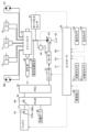
- FIG. 2 is a block diagram showing a system configuration of the electric shovel shown in FIG. 1 .
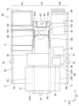
- FIG. 2 is a plan view showing the configuration of a rotating frame and the arrangement of items mounted on the rotating frame.
- FIG. 2 is a side view showing the configuration of the rotating frame and the arrangement of its mounted items.
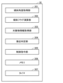
- FIG. 2 is a diagram illustrating functional blocks of a controller.
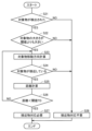
- 5 is a flowchart showing a flow of a process for cutting off current supply to a power storage device.
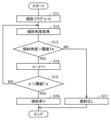
- 10 is a flowchart showing a process for determining an inclination of a vehicle body.
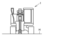
- FIG. 2 is a schematic diagram of an electric shovel when viewed from the front with the vehicle body not tilted.
- a plan view refers to a viewpoint when the revolving frame 20 is viewed from above along the revolving axis RX.
- the right front camera 51 and the right rear camera 52 are positioned on the right edge of the upper surface of the exterior cover 9.
- the right front camera 51 is positioned further forward than the right rear camera 52.
- the right front camera 51 captures an image of the right front of the rotating body 3.
- the optical axis of the right front camera 51 extends diagonally forward and to the right from the right front camera 51.
- the right rear camera 52 captures an image of the right rear of the rotating body 3.
- the optical axis of the right rear camera 52 extends diagonally rear and to the right from the right rear camera 52.
- the boom 6 can be driven relative to the vehicle body 1 by the boom cylinder 10. This drive allows the boom 6 to rotate vertically relative to the rotating body 3, with the boom foot pin 13 as a fulcrum.
- One end of the boom cylinder 10 is connected to the rotating body 3, and the other end is connected to the boom 6.
- Battery 37 is a power storage device that stores electrical energy. Battery 37 extracts the stored electrical energy as electromotive force.
- Battery 37 includes, for example, a plurality of battery modules. Each of the plurality of battery modules has a plurality of battery cells. The battery cells are formed, for example, by stacking positive and negative electrodes with a separator interposed therebetween.
- An EPC (electromagnetic proportional control) valve 46 is provided in the pilot oil passage.
- the EPC valve 46 adjusts the pilot oil supplied to the main valve 41 according to a control signal V1 from the controller 30. In this way, the EPC valve 46 controls the main valve 41.
- each valve in the main valve 41 is controlled according to the operation of the operator in the cab 4.
- the body 1 and working equipment 2 of the electric shovel 100 can be operated according to the driving operation of the operator. Specifically, the operator can operate the working equipment 2 by operating the hydraulic cylinders 10, 11, and 12, can operate the rotation of the rotating body 3 relative to the traveling body 5 by operating the turning motor 24, and can operate the traveling of the electric shovel 100 by operating the traveling motor 5M.
- the pump pressure sensor 47 detects the pressure of the hydraulic oil in the hydraulic piping between the hydraulic pump 43 and the main valve 41.
- the hydraulic oil pressure data detected by the pump pressure sensor 47 is input to the controller 30.
- the controller 30 includes a CPU (Central Processing Unit) and memory, and controls the operation of the electric excavator 100 by executing a control program stored in the memory.
- CPU Central Processing Unit
- a vehicle body IMU 60 is attached to the rotating body 3, typically the rotating frame 20.
- the vehicle body IMU 60 measures the acceleration of the rotating body 3 in the forward/backward, left/right, and up/down directions, and the angular velocity of the rotating body 3 about the forward/backward, left/right, and up/down directions.
- the acceleration and angular velocity of the rotating body 3 detected by the vehicle body IMU 60 are input to the controller 30.
- the vehicle body IMU 60 corresponds to an example of an inclination sensor that detects the inclination of the vehicle body 1 of the electric excavator 100.
- the image of the target to the right front of the electric shovel 100 captured by the right front camera 51 is input to the controller 30.
- the image of the target to the right rear of the electric shovel 100 captured by the right rear camera 52 is input to the controller 30.
- the image of the target to the rear of the electric shovel 100 captured by the rear camera 53 is input to the controller 30.
- the image of the target to the left of the electric shovel 100 captured by the left camera 54 is input to the controller 30.
- the high-voltage junction box 36 includes a relay 36Ry.
- the battery 37 includes a relay 37Ry.
- the relays 36Ry and 37Ry function as cutoff units that cut off electrical connections.
- the relay 37Ry opens and closes according to a control signal R1 sent from the controller 30.
- the relay 36Ry opens and closes according to a control signal R2 sent from the controller 30.
- the controller 30 cuts off the transmission of power between the battery 37 and the electric circuit connected to the battery 37 by cutting off one or both of the relays 36Ry and 37Ry.
- the controller 30 can cut off the flow of electricity to the battery 37 by cutting off at least one of the relays 36Ry and 37Ry.
- other relays, switches, circuit breakers, contactors, etc. may be provided in the electric devices or high-voltage wiring that make up the electric circuit.
- Fig. 3 is a plan view showing the configuration of the revolving frame 20 and the arrangement of items mounted thereon in the electric shovel 100 shown in Fig. 1.
- Fig. 4 is a side view showing the configuration of the revolving frame 20 and the arrangement of items mounted thereon in the electric shovel 100 shown in Fig. 1.
- the swivel frame 20 has a center frame CF, a left deck DL, and a right deck DR.
- the center frame CF, the left deck DL, and the right deck DR each extend in the front-to-rear direction D1.
- the center frame CF is located between the left deck DL and the right deck DR in the left-to-right direction D2 that is perpendicular to the front-to-rear direction D1 in a plan view.
- the left deck DL is disposed to the left of the center frame CF.
- the right deck DR is disposed to the right of the center frame CF.
- Through holes TH1 are formed in each of the pair of center beams CB.
- Boom foot pins 13 ( Figure 1) are inserted through the through holes TH1.
- the boom 6 ( Figure 1) is rotatably supported on the pair of center beams CB by the boom foot pins 13.
- a pin (not shown) that supports the boom cylinder 10 ( Figure 1) is inserted through the through hole TH2.
- the boom cylinder 10 is rotatably supported by the center frame CF via this pin.
- the swivel frame 20 has a front end and a rear end.
- the front end of the swivel frame 20 is made up of the front end FL of the left deck DL, the front end FR of the right deck DR, and the front end FC of the center frame CF.
- the rear end of the swivel frame 20 is made up of the rear end RL of the left deck DL, the rear end RR of the right deck DR, and the rear end RC of the center frame CF.
- the front end FL of the left deck DL and the front end FR of the right deck DR are each located forward of the front end FC of the center frame CF in the fore-and-aft direction D1.
- the rear end RC of the center frame CF is located rearward of the rear end RL of the left deck DL and the rear end RR of the right deck DR in the fore-and-aft direction D1.
- the rear end RC of the center frame CF is the rearmost end of the swivel frame 20.
- the rotating frame 20 carries loads such as the operator's cab 4, battery 37, electric motor 40, hydraulic oil tank 42, and hydraulic pump 43.
- the battery 37 is a power source that stores electrical energy obtained from an external power source.
- the battery 37 supplies power to the inverter 31 (FIG. 2) through high-voltage wiring.
- the electric shovel 100 of this embodiment does not have a counterweight, and the battery 37 plays the role of the counterweight. For this reason, the battery 37 is disposed at the rear of the rotating body 3.
- the battery 37 has a portion that is located rearward (away from the front end of the rotating frame 20) from the rear end RL of the left deck DL and the rear end RR of the right deck DR in a plan view.
- the rear end 37Rr of the battery 37 is located rearward in the fore-and-aft direction D1 from the rear end RL of the left deck DL and the rear end RR of the right deck DR in a plan view.
- the space located forward of the rear end RL of the left deck DL and the rear end RR of the right deck DR and covered by the exterior cover 9 constitutes the machinery room.
- the front end 37Fr of the battery 37 is located forward of the rear end RL of the left deck DL and the rear end RR of the right deck DR (near the front end of the rotating frame 20). As a result, in a plan view, the battery 37 protrudes into the machinery room.
- the left end 37L of the battery 37 has a portion located directly above the left deck DL and a portion located rearward of the rear end RL of the left deck DL.
- the right end 37R of the battery 37 has a portion located directly above the right deck DR and a portion located rearward of the rear end RR of the right deck DR.
- the electric motor 40, hydraulic oil tank 42, and hydraulic pump 43 are supported on the right deck DR.
- the electric motor 40 is located forward of the battery 37 in the fore-and-aft direction D1.
- the battery 37, electric motor 40, hydraulic pump 43, and hydraulic oil tank 42 are arranged in this order from rear to front in the fore-and-aft direction D1.
- the power distribution unit 35 is arranged, for example, above the electric motor 40.
- the charging port 38 is arranged in front of the hydraulic oil tank 42.
- the charging port 38 is adjacent to the hydraulic oil tank 42 in the fore-and-aft direction D1.
- the charging port 38 is arranged near the right side plate 9R of the exterior cover 9.
- the power storage device temperature management system 39 is a temperature adjustment device for monitoring and controlling the temperature of the battery 37.
- the power storage device temperature management system 39 is disposed in front of the battery 37 and faces the front end 37Fr of the battery 37.
- the power storage device temperature management system 39 is disposed above the center frame CF and above the left deck DL.
- the power storage device temperature management system 39 is disposed below the top surface of the battery 37 in the vertical direction.
- the right front camera 51 and the right rear camera 52 are positioned near the right side plate 9R of the exterior cover 9.
- the right front camera 51 and the right rear camera 52 may be positioned so as to overlap with the right side plate 9R of the exterior cover 9 in a plan view.
- the right front camera 51 and the right rear camera 52 are located to the right of the battery 37.
- the right front camera 51 and the right rear camera 52 are positioned in front of the front end 37Fr of the battery 37.
- the right front camera 51 and the right rear camera 52 are positioned to the right of the right end 37R of the battery 37.
- the vehicle body IMU 60 is mounted on the center frame CF.
- the vehicle body IMU 60 is disposed near the front end of the rotating frame 20.
- the vehicle body IMU 60 is disposed near the front end FC of the center frame CF.
- the vehicle body IMU 60 is disposed forward of the rotation axis RX of the rotating frame 20.
- the vehicle body IMU 60 is disposed between a pair of through holes TH2 in the left-right direction D2.
- Fig. 5 is a diagram for explaining the functional blocks of the controller 30 in the embodiment.
- FIG. 6 is a flowchart showing the process flow for cutting off the power supply to the power storage device by the electric excavator 100 in this embodiment.
- step S15 the tilt flag calculation unit 302 compares the current value of the tilt flag ⁇ with the tilt flag threshold T ⁇ .
- the tilt flag threshold T ⁇ is stored in the memory 306.
- the tilt flag calculation unit 302 reads the threshold T ⁇ from the memory 306.
- the tilt flag calculation unit 302 determines whether the current value of the tilt flag ⁇ after being incremented in the previous step S14 is greater than the threshold T ⁇ .
- step S13 If it is determined in step S13 that the inclination angle of the vehicle body 1 is equal to or less than the angle threshold value TA, the process proceeds to step S17.
- step S17 the controller 30 determines that the inclination of the vehicle body 1 is small, and that there is no risk of the vehicle body 1 sliding or tipping over and damaging the battery 37.
- FIG. 11 is a flowchart showing the process flow for determining whether or not an approaching object needs to be dealt with.
- the object information acquisition unit 303 of the controller 30 determines whether or not an object has been detected.
- An object is an object that exists around the body 1 of the electric shovel 100. Among the objects, an object that may cause the electric shovel 100 to collide with it if it moves toward the electric shovel 100 is referred to as an approaching object.
- An approaching object is detected by imaging devices mounted on the body 1 (right front camera 51, right rear camera 52, rear camera 53, and left camera 54; see FIGS. 1 to 3) capturing an image of the approaching object.
- Images captured by the right front camera 51, right rear camera 52, rear camera 53, and left camera 54 are input to the object information acquisition unit 303 of the controller 30.
- the object information acquisition unit 303 analyzes the captured images to determine whether or not an object is present around the body 1 of the electric shovel 100.
- the object is, for example, a flying object that is flying around the body 1.
- the object is, for example, another self-propelled work machine.
- the other work machine may be a transport machine, such as a dump truck, that transports the excavation object to be excavated by the work implement 2 of the electric shovel 100.
- step S23 the approach determination unit 304 of the controller 30 calculates the moving direction of the object.
- the approach determination unit 304 reads the time from the timer 307 and associates the time with the captured image input to the object information acquisition unit 303 to determine the time at which the image was captured.
- the approach determination unit 304 can determine whether or not an object is approaching the vehicle body 1 by comparing an object in an image captured at a certain time with the same object in an image captured a predetermined time later.
- An object moving in a direction away from the electric shovel 100 is unlikely to collide with the vehicle body 1 of the electric shovel 100.
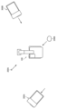
- an object moving in a direction approaching the electric shovel 100 such as the flying object 200B and the transport machine 300B, is considered to have a possibility of colliding with the vehicle body 1 of the electric shovel 100.
- step S25 the approach determination unit 304 determines the distance between the vehicle body 1 and the object by analyzing the captured image input to the object information acquisition unit 303.
- step S26 the approach determination unit 304 determines whether the distance between the vehicle body 1 and the object is smaller than the distance threshold TD.
- the distance threshold TD is stored in the memory 306.
- the approach determination unit 304 reads the distance threshold TD from the memory 306.
- the approach determination unit 304 compares the distance between the vehicle body 1 and the object with the distance threshold TD.
- the distance between the electric shovel 100 and the object is relatively large, as in the case of the transport machine 300B shown in FIG. 12, it will take some time for the object to collide with the vehicle body 1.
- the distance between the electric shovel 100 and the object is small and the object approaches very close to the vehicle body 1, as in the case of the flying object 200B, it is likely that the object will collide with the vehicle body 1 immediately.
- step S21 If it is determined in step S21 that an object has not been detected (NO in step S21), the process proceeds to step S28. If it is determined in step S22 that the size of the object is equal to or smaller than the dimension threshold value TS, the process proceeds to step S28. If it is determined in step S24 that an object is not approaching, the process proceeds to step S28. In step S28, the controller 30 determines that there is no approaching object and that the approaching object will not collide with the vehicle body 1 and therefore there is no risk of damage to the battery 37, or that the approaching object is small and therefore there is no risk of damage to the battery 37 even if it collides with the vehicle body 1.
- step S2 if it is determined in step S2 that the vehicle body 1 is tilted (YES in step S2), it is determined that the vehicle body 1 is slipping or tipping over and there is a risk of damaging the battery 37, and the process proceeds to step S4. Also, if it is determined in step S3 that it is necessary to respond to an approaching object (YES in step S3), it is determined that the battery 37 is in a situation where a collision with the approaching object could cause damage, and the process proceeds to step S4. In step S4, the control command unit 305 of the controller 30 cuts off the power to the battery 37.
- control command unit 305 transmits a control signal R1 to a relay 37Ry included in the battery 37, and transmits a control signal R2 to a relay 36Ry included in the high-voltage junction box 36.
- Relay 37Ry that receives the control signal R1 cuts off the electrical connection between the battery 37 and the high-voltage wiring.
- Relay 36Ry that receives the control signal R2 cuts off the electrical connection of the electrical circuit in the high-voltage junction box 36. This cuts off the transmission of power between the battery 37 and the electrical circuit electrically connected to the battery 37.
- the supply of power from the battery 37 to the electrical circuit for driving the electric motor 40 is cut off.
- the supply of power from the electrical circuit for charging the battery 37 to the battery 37 is cut off.
- the battery 37 By cutting off the power supply to the battery 37 and putting the battery 37 in a non-powered state, the battery 37 is prevented from being damaged even if an external impact is applied to the battery 37.
- step S3 after determining in step S2 whether the body 1 of the electric shovel 100 is tilted, it is determined in step S3 whether it is necessary to respond to an approaching object.
- the order of these determinations may be reversed. That is, if it is determined in step S1 that the electric shovel 100 is in the work mode or the charging mode, it may then be determined whether it is necessary to respond to an approaching object, and if it is determined that it is not necessary to respond to an approaching object, it may be determined whether the body 1 of the electric shovel 100 is tilted.
- the approaching object detection sensor that detects an object approaching the battery 37 is not limited to an imaging device.
- the approaching object detection sensor only needs to be able to detect the size of an object outside the electric shovel 100, the direction of movement of the object, and the distance to the object in a non-contact manner.
- LiDAR Light Detection and Ranging
- Radar Radio Detection and Ranging
- radio waves radio waves to obtain information about an object
- an ultrasonic sensor an infrared sensor, etc.
- the tilt sensor that detects the tilt of the vehicle body 1 is not limited to the vehicle body IMU 60, and may be any inclinometer. Multiple tilt sensors may be provided. Multiple tilt sensors of the same type may be provided. Multiple types of tilt sensors may be provided.
- the electric motor 40 is driven to rotate by power from the battery 37, the electric motor 40 drives the hydraulic pump 43, and the hydraulic actuator is driven by pressure oil generated by the hydraulic pump 43, thereby operating the work machine 2.
- the present invention is not limited to this example, and the electric motor 40 may convert electrical energy into mechanical energy, and the mechanical energy may be mechanically transmitted to the work machine 2 via a power transmission device to drive the work machine 2.
- the swing motor 24 may be an electric motor instead of a hydraulic motor.
- the travel motor 5M may also be an electric motor.
- the electric shovel 100 is given as an example of a work machine, but the present invention is not limited to the electric shovel 100 and can be applied to other types of work machines equipped with a battery 37 (electricity storage device).
- the work machine may be other types of electric work machines, such as an electric wheel loader, an electric bulldozer, or an electric dump truck.
- the work machine may be a hybrid machine equipped with both an engine and an electric motor.
- the indicators of damage to battery 37 due to an external impact are detected based on the detection results of the detection unit, and power to battery 37 is cut off in advance, so that battery 37 is in a non-powered state when an external impact is actually applied to battery 37. Even if the separator between the positive and negative electrodes is damaged due to the action of an external force on battery 37, it is possible to avoid a situation in which the positive and negative electrodes are short-circuited, causing a large current or a leakage current.
- the controller 30 compares the angle of inclination of the vehicle body 1 with the angle threshold value TA. If the vehicle body 1 is not inclined as shown in FIG. 8, there is little possibility that the vehicle body 1 will slip or roll over. As shown in FIG. 9, even if the vehicle body 1 is inclined, if the angle of inclination is small, the vehicle body 1 is stable on the inclined surface SL1, and there is little possibility that the vehicle body 1 will slip or roll over. On the other hand, as shown in FIG. 10, as the angle at which the vehicle body 1 is inclined increases, there is a greater possibility that the vehicle body 1 will slip or roll over.
- the angle threshold value TA related to the angle of inclination of the vehicle body 1 it is possible to determine whether the actual angle of inclination of the vehicle body 1 is greater than the angle threshold value TA, and to accurately determine the possibility of damage to the battery 37.
- the controller 30 determines that there is a risk of damage to the battery 37 when it is determined multiple times in succession that the angle of inclination of the vehicle body 1 is greater than the angle threshold value TA.
- the inclination of the vehicle body 1 is not determined based on a single detection by the inclination sensor (vehicle body IMU 60), but is determined based on the results of multiple determinations. This makes it possible to eliminate errors and noise from the inclination sensor. It is possible to accurately determine the possibility of damage to the battery 37, and it is possible to control the battery 37 to be powered off only when it is truly necessary.
Landscapes
- Engineering & Computer Science (AREA)
- Power Engineering (AREA)
- Mining & Mineral Resources (AREA)
- Structural Engineering (AREA)
- General Engineering & Computer Science (AREA)
- Civil Engineering (AREA)
- Mechanical Engineering (AREA)
- Transportation (AREA)
- Life Sciences & Earth Sciences (AREA)
- Sustainable Energy (AREA)
- Sustainable Development (AREA)
- Operation Control Of Excavators (AREA)
- Component Parts Of Construction Machinery (AREA)
Abstract
Description
図1は、実施形態における作業機械の一例としての電動ショベル100の構成を概略的に示す斜視図である。図1に示されるように、電動ショベル100は、車体(作業機械本体)1と、油圧により作動する作業機2とを有している。車体1は、旋回体3と、走行体5とを有している。
図2は、図1に示される電動ショベルのシステム構成を示すブロック図である。電動ショベル100は、動力源としての電動モータ40を備えている。電動ショベル100では、作業機2を駆動する駆動力を、電動モータ40が発生する。電動モータ40は、作業機2を駆動可能である。ブーム6、アーム7およびバケット8の各々が電動モータ40によって駆動されることにより、作業機2の動作が可能である。
図3は、図1に示される電動ショベル100における旋回フレーム20の構成およびその搭載物の配置を示す平面図である。図4は、図1に示される電動ショベル100における旋回フレーム20の構成およびその搭載物の配置を示す側面図である。
以下、蓄電装置(バッテリ37)の損傷を抑制するための、蓄電装置の保護制御について説明する。蓄電装置(バッテリ37)の損傷は、バッテリ37に衝撃が外部から加わることによる、バッテリ37の変形、短絡、漏電、構成要素の外れ、電解液などの筐体内の収容物の漏出、などを含む。図5は、実施形態におけるコントローラ30の機能ブロックを説明する図である。
上述した説明と一部重複する記載もあるが、本実施形態の特徴的な構成および作用効果についてまとめて記載すると、以下の通りである。
以上の説明は、以下に付記する特徴を含む。
蓄電装置と、
前記蓄電装置に損傷を与えるおそれがある状況を検出する検出部と、
コントローラとを備え、
前記コントローラは、前記検出部の検出結果に基づいて前記蓄電装置の損傷の可能性を判断し、前記蓄電装置に損傷を与えるおそれがあるときに、前記蓄電装置の通電を遮断する、作業機械。
前記蓄電装置に電気的に接続された電気回路をさらに備え、
前記コントローラは、前記蓄電装置と前記電気回路との間の電力の伝達を遮断する、付記1に記載の作業機械。
前記蓄電装置と前記電気回路との少なくともいずれか一方は、電気的接続を遮断する遮断部を含む、付記2に記載の作業機械。
前記蓄電装置を搭載する車体を備え、
前記検出部は、前記車体の傾斜を検出する傾斜センサを含む、付記1から付記3のいずれか1つに記載の作業機械。
前記コントローラは、前記傾斜センサにより求められる前記車体の傾斜の角度と、角度閾値とを比較する、付記4に記載の作業機械。
前記コントローラは、前記車体の傾斜の角度が前記角度閾値よりも大きいとの判断が複数回連続してなされた場合に、前記蓄電装置に損傷を与えるおそれがあると判断する、付記5に記載の作業機械。
前記検出部は、前記蓄電装置への接近物を検出する接近物検出センサを含む、付記1から付記6のいずれか1つに記載の作業機械。
前記コントローラは、前記接近物検出センサの検出結果より、前記接近物の大きさを求める、付記7に記載の作業機械。
前記コントローラは、前記接近物検出センサの検出結果より、前記作業機械と前記接近物との距離を求める、付記7または付記8に記載の作業機械。
前記コントローラは、前記接近物の大きさが寸法閾値よりも大きく、かつ、前記作業機械と前記接近物との距離が距離閾値よりも小さいと判断された場合に、前記蓄電装置に損傷を与えるおそれがあると判断する、付記9に記載の作業機械。
前記接近物検出センサは、前記接近物を撮像する少なくとも1つの撮像装置を含む、付記7から付記10のいずれか1つに記載の作業機械。
前記少なくとも1つの撮像装置は、複数の撮像装置を含み、
前記複数の撮像装置は、平面視において前記蓄電装置を取り囲むように配置される、付記11に記載の作業機械。
Claims (14)
- 蓄電装置と、
前記蓄電装置に損傷を与えるおそれがある状況を検出する検出部と、
コントローラとを備え、
前記コントローラは、前記検出部の検出結果に基づいて前記蓄電装置の損傷の可能性を判断し、前記蓄電装置に損傷を与えるおそれがあるときに、前記蓄電装置の通電を遮断する、作業機械。 - 前記蓄電装置に電気的に接続された電気回路をさらに備え、
前記コントローラは、前記蓄電装置と前記電気回路との間の電力の伝達を遮断する、請求項1に記載の作業機械。 - 前記蓄電装置と前記電気回路との少なくともいずれか一方は、電気的接続を遮断する遮断部を含む、請求項2に記載の作業機械。
- 前記蓄電装置を搭載する車体を備え、
前記検出部は、前記車体の傾斜を検出する傾斜センサを含む、請求項1に記載の作業機械。 - 前記コントローラは、前記傾斜センサにより求められる前記車体の傾斜の角度と、角度閾値とを比較する、請求項4に記載の作業機械。
- 前記コントローラは、前記車体の傾斜の角度が前記角度閾値よりも大きいとの判断が複数回連続してなされた場合に、前記蓄電装置に損傷を与えるおそれがあると判断する、請求項5に記載の作業機械。
- 前記検出部は、前記蓄電装置への接近物を検出する接近物検出センサを含む、請求項1に記載の作業機械。
- 前記コントローラは、前記接近物検出センサの検出結果より、前記接近物の大きさを求める、請求項7に記載の作業機械。
- 前記コントローラは、前記接近物検出センサの検出結果より、前記作業機械と前記接近物との距離を求める、請求項8に記載の作業機械。
- 前記コントローラは、前記接近物の大きさが寸法閾値よりも大きく、かつ、前記作業機械と前記接近物との距離が距離閾値よりも小さいと判断された場合に、前記蓄電装置に損傷を与えるおそれがあると判断する、請求項9に記載の作業機械。
- 前記接近物検出センサは、前記接近物を撮像する少なくとも1つの撮像装置を含む、請求項7に記載の作業機械。
- 前記少なくとも1つの撮像装置は、複数の撮像装置を含み、
前記複数の撮像装置は、平面視において前記蓄電装置を取り囲むように配置される、請求項11に記載の作業機械。 - 蓄電装置と、
前記蓄電装置に損傷を与えるおそれがある状況を検出する検出部と、
コントローラとを備え、
前記コントローラは、前記検出部の検出結果に基づいて前記蓄電装置の損傷の可能性を判断し、前記蓄電装置に損傷を与えるおそれがあるときに、前記蓄電装置の通電を遮断する、作業機械を含むシステム。 - 蓄電装置に損傷を与えるおそれがある状況を検出する検出部の検出結果を取得することと、
前記検出部の検出結果に基づいて前記蓄電装置の損傷の可能性を判断することと、
前記蓄電装置に損傷を与えるおそれがあるときに、前記蓄電装置の通電を遮断することと、を備える、作業機械の制御方法。
Priority Applications (3)
| Application Number | Priority Date | Filing Date | Title |
|---|---|---|---|
| KR1020257021939A KR20250114122A (ko) | 2023-01-05 | 2023-12-21 | 작업 기계, 작업 기계를 포함하는 시스템, 및 작업 기계의 제어 방법 |
| DE112023004556.9T DE112023004556T5 (de) | 2023-01-05 | 2023-12-21 | Arbeitsmaschine, system einschliesslich arbeitsmaschine und steuerungsverfahren für eine arbeitsmaschine |
| CN202380090494.4A CN120548394A (zh) | 2023-01-05 | 2023-12-21 | 作业机械、包括作业机械的系统及作业机械的控制方法 |
Applications Claiming Priority (2)
| Application Number | Priority Date | Filing Date | Title |
|---|---|---|---|
| JP2023000627A JP2024097222A (ja) | 2023-01-05 | 2023-01-05 | 作業機械、作業機械を含むシステム、および作業機械の制御方法 |
| JP2023-000627 | 2023-01-05 |
Publications (1)
| Publication Number | Publication Date |
|---|---|
| WO2024147296A1 true WO2024147296A1 (ja) | 2024-07-11 |
Family
ID=91803815
Family Applications (1)
| Application Number | Title | Priority Date | Filing Date |
|---|---|---|---|
| PCT/JP2023/045923 Ceased WO2024147296A1 (ja) | 2023-01-05 | 2023-12-21 | 作業機械、作業機械を含むシステム、および作業機械の制御方法 |
Country Status (5)
| Country | Link |
|---|---|
| JP (1) | JP2024097222A (ja) |
| KR (1) | KR20250114122A (ja) |
| CN (1) | CN120548394A (ja) |
| DE (1) | DE112023004556T5 (ja) |
| WO (1) | WO2024147296A1 (ja) |
Citations (6)
| Publication number | Priority date | Publication date | Assignee | Title |
|---|---|---|---|---|
| JP2010188988A (ja) * | 2009-02-18 | 2010-09-02 | Tomotada Enami | 青色光線衝突防止装置 |
| WO2013118874A1 (ja) * | 2012-02-10 | 2013-08-15 | 住友重機械工業株式会社 | ショベル |
| JP2017142585A (ja) * | 2016-02-09 | 2017-08-17 | 日立建機株式会社 | 建設機械の周囲障害物検知システム |
| JP2018026975A (ja) * | 2016-08-12 | 2018-02-15 | 株式会社デンソーテン | 振動判定装置、電源装置および振動判定方法 |
| JP2018145698A (ja) * | 2017-03-07 | 2018-09-20 | 住友重機械工業株式会社 | 作業機械 |
| JP2019090392A (ja) * | 2017-11-16 | 2019-06-13 | 日立オートモティブシステムズ株式会社 | 車両制御装置 |
-
2023
- 2023-01-05 JP JP2023000627A patent/JP2024097222A/ja active Pending
- 2023-12-21 WO PCT/JP2023/045923 patent/WO2024147296A1/ja not_active Ceased
- 2023-12-21 DE DE112023004556.9T patent/DE112023004556T5/de active Pending
- 2023-12-21 KR KR1020257021939A patent/KR20250114122A/ko active Pending
- 2023-12-21 CN CN202380090494.4A patent/CN120548394A/zh active Pending
Patent Citations (6)
| Publication number | Priority date | Publication date | Assignee | Title |
|---|---|---|---|---|
| JP2010188988A (ja) * | 2009-02-18 | 2010-09-02 | Tomotada Enami | 青色光線衝突防止装置 |
| WO2013118874A1 (ja) * | 2012-02-10 | 2013-08-15 | 住友重機械工業株式会社 | ショベル |
| JP2017142585A (ja) * | 2016-02-09 | 2017-08-17 | 日立建機株式会社 | 建設機械の周囲障害物検知システム |
| JP2018026975A (ja) * | 2016-08-12 | 2018-02-15 | 株式会社デンソーテン | 振動判定装置、電源装置および振動判定方法 |
| JP2018145698A (ja) * | 2017-03-07 | 2018-09-20 | 住友重機械工業株式会社 | 作業機械 |
| JP2019090392A (ja) * | 2017-11-16 | 2019-06-13 | 日立オートモティブシステムズ株式会社 | 車両制御装置 |
Also Published As
| Publication number | Publication date |
|---|---|
| CN120548394A (zh) | 2025-08-26 |
| KR20250114122A (ko) | 2025-07-28 |
| JP2024097222A (ja) | 2024-07-18 |
| DE112023004556T5 (de) | 2025-08-28 |
Similar Documents
| Publication | Publication Date | Title |
|---|---|---|
| US9206588B2 (en) | Shovel provided with electric swiveling apparatus and method of controlling the same | |
| US12241226B2 (en) | Image display system of work machine, remote operation system of work machine, work machine, and method for displaying image of work machine | |
| JP5004834B2 (ja) | 作業機械 | |
| CN113544339B (zh) | 挖土机 | |
| JP7091896B2 (ja) | 旋回式作業機械の安全装置 | |
| US12054913B2 (en) | Construction machine | |
| JP7521147B2 (ja) | 作業機械 | |
| CN104963373A (zh) | 挖土机及其控制方法 | |
| WO2021049409A1 (ja) | 建設機械 | |
| JP6291427B2 (ja) | ハイブリッド式作業機 | |
| EP4326946A1 (en) | Systems and methods for control of electrically powered power machines | |
| JP6964936B2 (ja) | 作業機械 | |
| US20240125093A1 (en) | Electric Work Machine | |
| US20220112693A1 (en) | Monitoring device and construction machine | |
| JP7666871B2 (ja) | 作業機械 | |
| JP2018017011A (ja) | 電気駆動式作業機械の移動用システム | |
| EP2518219B1 (en) | Device for driving/controlling ac motor | |
| JP5079674B2 (ja) | 電気駆動式作業機械 | |
| JP7683169B2 (ja) | 作業機械 | |
| JP2007228715A (ja) | 電源システムおよびこの電源システムが搭載された建設機械 | |
| JP2024097222A (ja) | 作業機械、作業機械を含むシステム、および作業機械の制御方法 | |
| JP2022160278A (ja) | 作業システム | |
| JP4228980B2 (ja) | 作業機械の旋回駆動装置 | |
| US20260015817A1 (en) | System including work machine and method of controlling work machine | |
| WO2020218308A1 (ja) | 作業機械 |
Legal Events
| Date | Code | Title | Description |
|---|---|---|---|
| 121 | Ep: the epo has been informed by wipo that ep was designated in this application |
Ref document number: 23914782 Country of ref document: EP Kind code of ref document: A1 |
|
| WWE | Wipo information: entry into national phase |
Ref document number: 112023004556 Country of ref document: DE |
|
| WWE | Wipo information: entry into national phase |
Ref document number: 202380090494.4 Country of ref document: CN |
|
| WWP | Wipo information: published in national office |
Ref document number: 1020257021939 Country of ref document: KR |
|
| WWP | Wipo information: published in national office |
Ref document number: 202380090494.4 Country of ref document: CN |
|
| WWP | Wipo information: published in national office |
Ref document number: 112023004556 Country of ref document: DE |
|
| 122 | Ep: pct application non-entry in european phase |
Ref document number: 23914782 Country of ref document: EP Kind code of ref document: A1 |