WO2024142255A1 - 紫外光発生装置および方法 - Google Patents
紫外光発生装置および方法 Download PDFInfo
- Publication number
- WO2024142255A1 WO2024142255A1 PCT/JP2022/048202 JP2022048202W WO2024142255A1 WO 2024142255 A1 WO2024142255 A1 WO 2024142255A1 JP 2022048202 W JP2022048202 W JP 2022048202W WO 2024142255 A1 WO2024142255 A1 WO 2024142255A1
- Authority
- WO
- WIPO (PCT)
- Prior art keywords
- light
- optical system
- solid medium
- pulse
- short
- Prior art date
- Legal status (The legal status is an assumption and is not a legal conclusion. Google has not performed a legal analysis and makes no representation as to the accuracy of the status listed.)
- Ceased
Links
Images




Classifications
-
- H—ELECTRICITY
- H01—ELECTRIC ELEMENTS
- H01S—DEVICES USING THE PROCESS OF LIGHT AMPLIFICATION BY STIMULATED EMISSION OF RADIATION [LASER] TO AMPLIFY OR GENERATE LIGHT; DEVICES USING STIMULATED EMISSION OF ELECTROMAGNETIC RADIATION IN WAVE RANGES OTHER THAN OPTICAL
- H01S3/00—Lasers, i.e. devices using stimulated emission of electromagnetic radiation in the infrared, visible or ultraviolet wave range
- H01S3/10—Controlling the intensity, frequency, phase, polarisation or direction of the emitted radiation, e.g. switching, gating, modulating or demodulating
Definitions
- the present invention relates to an ultraviolet light generating device and method capable of generating broadband ultraviolet light with high purity orbital angular momentum.
- Controlling the spatial modes of light, in particular the orbital angular momentum (OAM) of light, is essential for a variety of applications, including super-resolution microscopy, optical communications, quantum entanglement, microparticle manipulation, laser processing, and sensing of rotating objects (Non-Patent Documents 1-6).
- OAM orbital angular momentum
- OAM of light is expected to be applicable to super-resolution optical lithography technology (Non-Patent Document 7), and developing a method for controlling OAM is an important issue.
- Light with wavelengths from the visible region to the near-infrared region can be spatially phase controlled by directly passing it through a spatial phase plate, a phase hologram, or a plate with a nanostructure pattern (Non-Patent Document 8).
- a spatial phase plate a phase hologram, or a plate with a nanostructure pattern
- Non-Patent Document 9 a promising method for spatial phase modulation of deep ultraviolet light is to first apply a spatial phase pattern to light in the visible and infrared regions, and then convert it to the ultraviolet region using a nonlinear optical process.
- the most extreme example of a non-linear optical process is high-order harmonic generation, which can generate light up to the vacuum ultraviolet region that cannot be generated by normal non-linear optical processes such as second-order harmonic generation (Non-Patent Documents 10-12).
- High-order harmonic generation is a phenomenon in which a medium is irradiated with a high-intensity, ultrashort pulse laser with a broadband spectrum, and light with a frequency that is an integer multiple of the irradiated light is generated.
- Non-Patent Documents 10, 11 polarization control of excitation light using liquid crystal elements has been used in high-order harmonic generation in gas or solid media.
- liquid crystal elements are designed for specific wavelengths, and when such liquid crystal elements are applied to broadband excitation light for high-order harmonic generation, a problem of deterioration in OAM purity occurs.
- linear phase defects appear for broadband light, spatial chromatic dispersion occurs, and the polarization state of each color is non-uniform (Non-Patent Document 8).
- the present invention has been made to solve the above problems, and aims to provide an ultraviolet light generating device and method that can generate broadband ultraviolet light with high purity orbital angular momentum without using nanostructures or liquid crystal elements.
- the ultraviolet light generating device of the present invention is characterized by comprising a short-pulse light generating device configured to generate mid-infrared short-pulse light, a first optical system configured to convert the mid-infrared short-pulse light into circularly polarized light, a first solid medium having refractive index anisotropy, and a second optical system configured to focus the light emitted from the first optical system and irradiate the first solid medium.
- the ultraviolet light generating method of the present invention is characterized by including a first step of generating a mid-infrared short-pulse light, a second step of converting the mid-infrared short-pulse light into circularly polarized light by a first optical system, and a third step of concentrating the light emitted from the first optical system by a second optical system and irradiating the light onto a first solid medium having refractive index anisotropy.
- the present invention by providing a short-pulse light generating device, a first optical system, a first solid medium, and a second optical system, high-order harmonic generation occurs via the spin-orbit interaction of light, which is a property arising from the first solid medium, and light in the deep ultraviolet and vacuum ultraviolet regions with high purity orbital angular momentum can be generated. Since the present invention uses a homogeneous first solid medium instead of a commonly used optical phase modulation element made of liquid crystal or the like, it is possible to easily generate broadband ultraviolet light. Since the present invention can generate light with high purity orbital angular momentum up to the deep ultraviolet and vacuum ultraviolet regions by using high-order harmonic generation, it is expected to be used as a light source for improving the spatial resolution of optical lithography. In addition, the present invention is expected to be applied to new spectroscopic techniques and sensing.
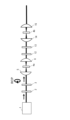
- FIG. 1 is a block diagram showing the configuration of an ultraviolet light generating apparatus according to a first embodiment of the present invention.
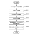
- FIG. 2 is a flow chart for explaining the process flow of the ultraviolet light generating method according to the first embodiment of the present invention.
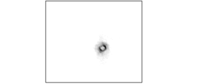
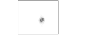
- 3A and 3B are diagrams showing the spatial profiles of right-handed circularly polarized light and left-handed circularly polarized light of the third harmonic.
- 3C and 3D are diagrams showing the spatial profiles of right-handed circularly polarized light and left-handed circularly polarized light of the fourth harmonic.
- 3E to 3F are diagrams showing the spatial profiles of right-handed circularly polarized light and left-handed circularly polarized light of the fifth harmonic.
- FIG. 4 is a block diagram showing the configuration of an ultraviolet light generating apparatus according to a second embodiment of the present invention.
- FIG. 5 is a flow chart for explaining the process flow of the ultraviolet light generating method according to the second embodiment of the present invention.
- high-order harmonics are generated through the spin-orbit interaction (SOI), a property of solid media, to generate light in the deep ultraviolet or vacuum ultraviolet region with high OAM purity.
- SOI spin-orbit interaction
- E. Brassellet et al. "Dynamics of optical spin-orbit coupling in uniaxial crystals", Optics letters, vol. 34, pp. 1021-1023, 2009.
- the spin angular momentum degree of freedom and the orbital angular momentum degree of freedom corresponding to circularly polarized light are independent.
- SOI is a phenomenon that causes an exchange of light intensity between the spin angular momentum degree of freedom and the orbital angular momentum degree of freedom corresponding to circularly polarized light. This phenomenon occurs as a result of birefringence when laser light is focused with a high NA (Numerical Aperture) in a homogeneous crystal with refractive index anisotropy. Since anisotropic refractive index exists in a wide band in many media, it can be used for OAM conversion in a wide band of optical frequencies.
- the polarizer 2 and the quarter-wave plate 3 constitute the first optical system.
- a right-handed circularly polarized pulse (RCP) is generated by passing the mid-infrared short-pulse light emitted from the short-pulse light generator 1 through the polarizer 2 and the quarter-wave plate 3 ( Figure 2, step S101).
- a 2 mm thick ⁇ -GaSe crystal was used as the solid medium 4, and light was focused by a focusing lens 5 with a focal length of 6 mm to generate high-order harmonics.
- the solid medium 4 is preferably a medium having a large refractive index anisotropy, and solid crystals such as ⁇ -BaB 2 O 4 or artificial structures other than GaSe crystal may be used.
- the collimating lens 6 converts the high-order harmonics generated by the solid medium 4 into parallel light (Fig. 2, step S103).
- the parallel light is passed through a broadband quarter-wave plate 7 and a polarizer 8 to extract only one of the circularly polarized lights of the high-order harmonics (Fig. 2, step S104).
- the color filter 9 passes only a specific order of harmonics from the circularly polarized light that has passed through the polarizer 8 (Fig. 2, step S105). In this way, in this embodiment, light in the deep ultraviolet and vacuum ultraviolet regions can be generated.
- Figure 3A shows the spatial profile of the right-handed circularly polarized (RCP) third harmonic acquired by the CMOS camera 11
- Figure 3B shows the spatial profile of the left-handed circularly polarized (LCP) third harmonic.
- RCP right-handed circularly polarized
- LCP left-handed circularly polarized
- Figure 3C shows the spatial profile of right-handed circularly polarized fourth harmonic light acquired by the CMOS camera 11, and Figure 3D shows the spatial profile of left-handed circularly polarized fourth harmonic light.
- CMOS camera 11 shows the spatial profile of right-handed circularly polarized fourth harmonic light.
- Figure 3D shows the spatial profile of left-handed circularly polarized fourth harmonic light.
- a profile with multiple intensity nodes in the angular direction of the beam was observed. These nodes are a characteristic profile obtained by interference of multiple orbital angular momentum components that exist simultaneously.
- the profile clearly has six nodes, indicating the occurrence of multiple states of light with an OAM difference of six.
- Non-Patent Document 12 Non-Patent Document 12
- collimating lens 6, quarter-wave plate 7, polarizer 8, color filter 9, focusing lens 10, and CMOS camera 11 are components for observing the spatial profile, and are not essential components of the present invention.
- FIG. 4 is a block diagram showing the configuration of an ultraviolet light generating device according to a second embodiment of the present invention.
- the ultraviolet light generating device of this embodiment includes a short pulse light generating device 1, a polarizer 2, a quarter-wave plate 3, a solid medium 4a, a focusing lens 5 (second optical system), a collimating lens 6 (third optical system), a quarter-wave plate 12, a polarizer 13, a focusing lens 14, a solid medium 4b, and a collimating lens 15.
- FIG. 5 is a flow chart explaining the process flow of the ultraviolet light generation method of this embodiment.
- the configuration including a solid medium, a condenser lens, and a collimator lens is increased to two, and a solid medium 4a, a condenser lens 5, and a collimator lens 6 are used to generate finite OAM light by the SOI of light.
- the configuration consisting of a polarizer 2, a quarter-wave plate 3, a solid medium 4a, a condenser lens 5, and a collimator lens 6 is the same as in the first embodiment, and the processes of steps S100 to S103 in FIG. 5 are as explained in the first embodiment.
- the solid medium 4a has a refractive index anisotropy like the solid medium 4 in the first embodiment.
- the solid medium 4b, the condenser lens 14, and the collimator lens 15 are used for high-order harmonic generation.
- the solid medium 4b may be any medium that is a solid capable of generating high-order harmonic waves, and examples thereof include solid crystals such as SiO2 and MgO.
- a quarter-wave plate 12 and a polarizer 13 are inserted between the collimating lens 6 and the focusing lens 14.
- the quarter-wave plate 12 and the polarizer 13 constitute a fourth optical system.
- setting the long axis of the quarter-wave plate 12 and the transmission axis of the polarizer 13 at 45 degrees it is possible to selectively pass light having an OAM of 2 out of the light emitted from the collimating lens 6 (step S106 in FIG. 5).
- setting the long axis of the quarter-wave plate 12 and the transmission axis of the polarizer 13 at 45 degrees means that, assuming that there is no solid medium 4a, the light emitted from the collimating lens 6 does not pass through the quarter-wave plate 12 and the polarizer 13.
- the focusing lens 14 (fifth optical system) focuses the linearly polarized pulse that has passed through the polarizer 13 and irradiates the solid medium 4b (step S107 in FIG. 5).
- the collimating lens 15 converts the high-order harmonics generated by the solid medium 4b into parallel light (step S108 in FIG. 5).
- High-order harmonics generated by the solid medium 4b can generate ultraviolet light with an OAM that is an integer multiple of the OAM of the light that exits the collimating lens 6.
Landscapes
- Physics & Mathematics (AREA)
- Electromagnetism (AREA)
- Engineering & Computer Science (AREA)
- Plasma & Fusion (AREA)
- Optics & Photonics (AREA)
- Liquid Crystal (AREA)
- Lasers (AREA)
- Optical Modulation, Optical Deflection, Nonlinear Optics, Optical Demodulation, Optical Logic Elements (AREA)
Abstract
紫外光発生装置は、中赤外短パルス光を発生する短パルス光発生装置(1)と、中赤外短パルス光を円偏光に変換する偏光子(2)および1/4波長板(3)と、屈折率異方性を有する固体媒質(4)と、1/4波長板(3)を出射した光を集光して固体媒質(4)に照射する集光レンズ(5)とを備える。
Description
本発明は、純度の高い軌道角運動量を有する広帯域の紫外光を生成することができる紫外光発生装置および方法に関するものである。
光の空間モードの制御、特に光の軌道角運動量(OAM:Orbital angular momentum)の制御は、超解像顕微技術、光通信、量子エンタングルメント、マイクロ粒子操作、レーザー加工、回転体のセンシングなど多様な応用に不可欠である(非特許文献1~6)。
特に紫外域における光のOAMは超解像光リソグラフィー技術に応用できると期待されており(非特許文献7)、OAMの制御方法の開拓は重要な課題である。可視領域から近赤外領域の波長の光は、直接的に空間位相プレートや位相ホログラム、ナノ構造パターンを有するプレートなどを通すことで空間的光位相制御が可能である(非特許文献8)。しかしながら、深紫外域より短波長の領域では、対応する素子がないために光の空間位相を制御することが困難である。
そのため、深紫外光の空間位相変調のためにはまず可視領域、赤外領域の光に対して空間的位相パターンを施した後に、非線形光学過程によって紫外領域に変換する方法が有望である(非特許文献9)。非線形光学過程で最も極端な例が高次高調波発生であり、第2次高調波発生などの通常の非線形光学過程では発生できない真空紫外領域までの光が発生可能である(非特許文献10~12)。高次高調波発生は、広帯域なスペクトルをもつ高強度の超短パルスレーザーを媒質に照射し、照射した光の整数倍の周波数の光を発生する現象である。
従来の例では、気体や固体媒質における高次高調波発生において液晶素子による励起光の偏光制御が用いられてきた(非特許文献10,11)。ただし、液晶素子は特定の波長用に設計された素子であり、このような液晶素子を高次高調波発生の広帯域な励起光に適用する場合はOAMの純度の悪化という問題が起きる。例えば液晶素子やナノ構造体によって作られるらせん位相プレート、ホログラム、q-plateを用いる手法の場合、広帯域な光に対しては線状の位相欠陥の出現、空間的な色分散、色ごとの偏光状態の不均一性などが生じる(非特許文献8)。結果として純度の高いOAMをもつ深紫外領域、真空紫外領域の光の発生は困難であった。
上述のように、深紫外領域、真空紫外領域において光の空間位相の直接的な制御は困難であり、可視光や赤外光の空間位相を制御した後に高次高調波発生による波長変換を行うことが有望な手法である。通常、励起光の位相制御に用いられる素子は特定波長に対してはよく働くが、高次高調波発生に必要な広帯域な光に対しては高い純度のOAMを生成できず、結果として得られる深紫外領域、真空紫外領域の光のOAMの純度が悪いという課題があった。
K.I.Willig et al.,"STED microscopy reveals that synaptotagmin remains clustered after synaptic vesicle exocytosis",Nature,vol.440,pp.935-939,2006
J.Wang et al.,"Terabit free-space data transmission employing orbital angular momentum multiplexing",Nature photonics,vol.6,pp.488-496,2012
K.Toyoda et al.,"Using optical vortex to control the chirality of twisted metal nanostructures",Nano letters 12,pp.3645-3649,2012
M.Padgett and B.Richard,"Tweezers with a twist",Nature photonics,vol.5,pp.343-348,2011
A.Mair et al.,"Entanglement of the orbital angular momentum states of photons",Nature,vol.412,pp.313-316,2001
Martin P.J.Lavery et al.,"Detection of a spinning object using light's orbital angular momentum",Science,vol.341,pp.537-540,2013
T.F.Scott et al.,"Two-color single-photon photoinitiation and photoinhibition for subdiffraction photolithography",Science,vol.324,pp.913-917,2009
X.Wang et al.,"Recent advances on optical vortex generation",Nanophotonics,vol.7,pp.1533-1556,2018
K.Dholakia et al.,"Second-harmonic generation and the orbital angular momentum of light",Physical Review A,vol. 54,R3742,1996
M.Zurch et al.,"Strong-field physics with singular light beams"Nature Physics,vol.8,pp.743-746,2012
D.Gauthier et al.,"Orbital angular momentum from semiconductor high-order harmonics",Optics letters,vol.44,pp.546-549,2019
S.Ghimire and David A. Reis,"High-harmonic generation from solids",Nature physics,vol.15,pp.10-16,2019
本発明は、上記課題を解決するためになされたもので、ナノ構造体や液晶素子を用いることなく、純度の高い軌道角運動量を有する広帯域の紫外光を生成することができる紫外光発生装置および方法を提供することを目的とする。
本発明の紫外光発生装置は、中赤外短パルス光を発生するように構成された短パルス光発生装置と、前記中赤外短パルス光を円偏光に変換するように構成された第1の光学系と、屈折率異方性を有する第1の固体媒質と、前記第1の光学系を出射した光を集光して前記第1の固体媒質に照射するように構成された第2の光学系とを備えることを特徴とするものである。
また、本発明の紫外光発生方法は、中赤外短パルス光を発生する第1のステップと、前記中赤外短パルス光を第1の光学系によって円偏光に変換する第2のステップと、前記第1の光学系を出射した光を第2の光学系によって集光して、屈折率異方性を有する第1の固体媒質に照射する第3のステップとを含むことを特徴とするものである。
本発明によれば、短パルス光発生装置と第1の光学系と第1の固体媒質と第2の光学系とを設けることにより、第1の固体媒質から生じる性質である光のスピン軌道相互作用を介して、高次高調波発生を起こすことで、純度の高い軌道角運動量を有する深紫外領域、真空紫外領域の光を生成することができる。本発明は、通常用いられる液晶等からなる光位相変調素子ではなく、均質な第1の固体媒質を用いるため、広帯域の紫外光を簡便に生成可能である。本発明は、高次高調波発生を用いることで深紫外領域、真空紫外領域まで純度の高い軌道角運動量を有する光を生成できるため、光リソグラフィーの空間分解能向上のための光源としての利用が期待できる。また、本発明は、新たな分光技術やセンシングに対する応用が期待できる。
[発明の原理]
本発明では、固体媒質から生じる性質である光のスピン軌道相互作用(SOI:Spin-Orbit Interaction)を介して高次高調波発生を起こすことで、高いOAMの純度を有する、深紫外領域や真空紫外領域の光を生成する。SOIについては、例えば文献「E.Brasselet et al.,“Dynamics of optical spin-orbit coupling in uniaxial crystals”,Optics letters,vol.34,pp.1021-1023,2009」に記載されている。
本発明では、固体媒質から生じる性質である光のスピン軌道相互作用(SOI:Spin-Orbit Interaction)を介して高次高調波発生を起こすことで、高いOAMの純度を有する、深紫外領域や真空紫外領域の光を生成する。SOIについては、例えば文献「E.Brasselet et al.,“Dynamics of optical spin-orbit coupling in uniaxial crystals”,Optics letters,vol.34,pp.1021-1023,2009」に記載されている。
本発明では、OAMを持たない広帯域の超短パルスレーザー光を広帯域な1/4波長板に通した後に固体媒質中で光のSOIを引き起こし、SOIの出現と同時またはその後に高次高調波発生を行う。これにより、本発明では、純度の高いOAMを有する、深紫外領域や真空紫外領域の光を生成可能とする。
通常、円偏光に対応するスピン角運動量自由度と軌道角運動量自由度とは独立の関係にある。SOIは、円偏光に対応するスピン角運動量自由度と軌道角運動量自由度との間で光強度のやりとりを起こす現象である。この現象は、屈折率異方性を有する均質な結晶中に高いNA(Numerical Aperture)でレーザー光を集光した際に複屈折の結果として生じる。異方的な屈折率は、多くの媒質で広い帯域で存在するため、広帯域の光周波数におけるOAM変換に利用可能である。まず、ガウシアンビームに対して光のスピンに対応する円偏光を広帯域で付与した後に、光のスピン角運動量を軌道角運動量に変換すれば、特殊な空間位相変調素子を用いずに純度の高い軌道角運動量を有する光を生成可能である。生成した光を高次高調波発生に用いれば、結果として得られる深紫外領域や真空紫外領域の光も高い純度のOAMを有する。
[第1の実施例]
以下、本発明の実施例について図面を参照して説明する。図1は本発明の第1の実施例に係る紫外光発生装置の構成を示すブロック図である。紫外光発生装置は、短パルス光発生装置1と、偏光子2と、1/4波長板3と、固体媒質4と、集光レンズ5と、コリメートレンズ6と、1/4波長板7と、偏光子8と、カラーフィルター9とを備えている。
以下、本発明の実施例について図面を参照して説明する。図1は本発明の第1の実施例に係る紫外光発生装置の構成を示すブロック図である。紫外光発生装置は、短パルス光発生装置1と、偏光子2と、1/4波長板3と、固体媒質4と、集光レンズ5と、コリメートレンズ6と、1/4波長板7と、偏光子8と、カラーフィルター9とを備えている。
図2は本実施例の紫外光発生方法の処理の流れを説明するフローチャートである。短パルス光発生装置1は、固体高次高調波発生のために、軸対称な空間モードを有する高強度の中赤外短パルス光を発生する(図2ステップS100)。短パルス光発生装置1は、光源となるTi:Sapphireマルチパス増幅器と、光パラメトリック増幅器とから構成される。マルチパス増幅器から出力されるパルスレーザー光は、繰り返し周波数が3kHz、1パルスあたりのエネルギーが3mJ、パルス幅が20fsである。このパルスレーザー光を光パラメトリック増幅器によって波長2400nmの光に変換する。
偏光子2と1/4波長板3とは、第1の光学系を構成している。短パルス光発生装置1から放射された中赤外短パルス光を偏光子2と1/4波長板3とに通すことで右回り円偏光パルス(RCP)を生成する(図2ステップS101)。
固体媒質4は、光が照射される方向と垂直な面と、光が照射される方向と平行な軸との間で屈折率が異なる屈折率異方性を有する。高いNAの集光レンズ5(第2の光学系)は、1/4波長板3を通過した右回り円偏光パルスを集光して固体媒質4に照射する(図2ステップS102)。
本実施例では、固体媒質4として厚さ2mmのε-GaSe結晶を用い、焦点距離6mmの集光レンズ5によって光を集光して、高次高調波を発生させた。固体媒質4は、大きな屈折率異方性を有する媒質が好ましく、GaSe結晶以外にもβ-BaB2O4などの固体結晶や人工構造を用いてもよい。
コリメートレンズ6は、固体媒質4によって発生した高次高調波を平行光に変換する(図2ステップS103)。平行光を広帯域の1/4波長板7と偏光子8とに通すことで高次高調波の一方の円偏光のみを取り出す(図2ステップS104)。カラーフィルター9は、偏光子8を通過した円偏光のうち特定の次数の高調波のみを通過させる(図2ステップS105)。こうして、本実施例では、深紫外領域や真空紫外領域の光を生成することができる。
カラーフィルター9を通過した光を集光レンズ10によって集光し、CMOSカメラ11で空間プロファイルを観測した。なお、以下の図3A~図3Fでは、分かり易くするため、CMOSカメラ11の受光面上において光が検出された部分のみを黒く記載している。
図3AはCMOSカメラ11で取得した3次高調波の右周り円偏光(RCP)の空間プロファイルを示す図、図3Bは3次高調波の左回り円偏光(LCP)の空間プロファイルを示す図である。右周り円偏光、左回り円偏光のどちらの成分についても、中心に光強度が無い円環状の空間プロファイルが観測された。文献「N.Saito et al.,“Observation of selection rules for circularly polarized fields in high-harmonic generation from a crystalline solid”,Optica,vol.4,pp,1333-1336,2017」において報告された薄いGaSe結晶における固体HHG(high-harmonic generation)の光のスピン角運動量保存則によると、GaSeの面内の3回回転対称性により円偏光の光照射の下でGaSe結晶からの3次高調波は禁制になるはずである。
本実施例において3次高調波の円環状の空間プロファイルが観測されたことは、結晶内での励起光および高調波の伝搬中に光のスピン角運動量と軌道角運動量との間で光強度分布がやりとりされることによって、光の純粋なスピン角運動量保存則だけでは禁制だった高調波が許容になったと考えられる。
図3CはCMOSカメラ11で取得した4次高調波の右周り円偏光の空間プロファイルを示す図、図3Dは4次高調波の左回り円偏光の空間プロファイルを示す図である。右周り円偏光、左回り円偏光のどちらの偏光状態においても、ビームの角度方向に強度の節を複数持つようなプロファイルが観測された。この節は、同時に存在する複数の軌道角運動量成分が干渉して得られる特徴的なプロファイルである。図3Cにおいて、プロファイルが明確に6つの節を持つことは、OAMが6だけ異なる光の多重状態が発生していることを示す。
図3EはCMOSカメラ11で取得した5次高調波の右周り円偏光の空間プロファイルを示す図、図3Fは5次高調波の左回り円偏光の空間プロファイルを示す図である。3次高調波と同様に円環状のプロファイルになっていることから、有限のOAMを有する光になっていると考えられる。
本実施例では、5次までの高次高調波について示したが、励起光として使用するレーザーの周波数や非線形光学媒質、レーザー強度を最適化すれば、より高次で高い周波数の高調波を発生できるため(非特許文献12)、軌道角運動量の大きさの制御が可能な、深紫外領域や真空紫外域での光源を実現することができる。
なお、コリメートレンズ6と1/4波長板7と偏光子8とカラーフィルター9と集光レンズ10とCMOSカメラ11とは、空間プロファイルを観測するための構成であって、本発明において必須の構成要件ではない。
[第2の実施例]
次に、本発明の第2の実施例について説明する。第1の実施例では、1つの固体媒質内で光のSOIによる有限OAM光の発生と高次高調波発生とを行い、次数ごとに異なるOAMの多重状態が生成できることを示した。固体媒質を2つに分離した場合には、各次数で単一のOAM状態を生成することも可能である。
次に、本発明の第2の実施例について説明する。第1の実施例では、1つの固体媒質内で光のSOIによる有限OAM光の発生と高次高調波発生とを行い、次数ごとに異なるOAMの多重状態が生成できることを示した。固体媒質を2つに分離した場合には、各次数で単一のOAM状態を生成することも可能である。
図4は本発明の第2の実施例に係る紫外光発生装置の構成を示すブロック図である。本実施例の紫外光発生装置は、短パルス光発生装置1と、偏光子2と、1/4波長板3と、固体媒質4aと、集光レンズ5(第2の光学系)と、コリメートレンズ6(第3の光学系)と、1/4波長板12と、偏光子13と、集光レンズ14と、固体媒質4bと、コリメートレンズ15とを備えている。
図5は本実施例の紫外光発生方法の処理の流れを説明するフローチャートである。本実施例では、固体媒質と集光レンズとコリメートレンズとを含む構成を2つに増やし、固体媒質4aと集光レンズ5とコリメートレンズ6とを光のSOIによる有限OAM光の発生に用いる。偏光子2と1/4波長板3と固体媒質4aと集光レンズ5とコリメートレンズ6とからなる構成は、第1の実施例と同様であり、図5のステップS100~S103の処理は第1の実施例で説明したとおりである。固体媒質4aは、第1の実施例の固体媒質4と同様に屈折率異方性を有するものである。
固体媒質4bと集光レンズ14とコリメートレンズ15とは、高次高調波発生に使用される。固体媒質4bとしては、高次高調波発生が行える固体であればどのような媒質でもよく、例としてはSiO2やMgOなどの固体結晶が挙げられる。
コリメートレンズ6と集光レンズ14との間には、1/4波長板12と偏光子13とが挿入される。1/4波長板12と偏光子13とは、第4の光学系を構成している。1/4波長板12の長軸と偏光子13の透過軸とを45度に設定することで、コリメートレンズ6を出射した光のうち、OAMが2となる光を選択的に通過させることができる(図5ステップS106)。ここで、1/4波長板12の長軸と偏光子13の透過軸とを45度に設定することは、固体媒質4aが無いと仮定した場合に、コリメートレンズ6を出射した光が1/4波長板12と偏光子13とを通過しないことを意味する。
集光レンズ14(第5の光学系)は、偏光子13を通過した直線偏光パルスを集光して固体媒質4bに照射する(図5ステップS107)。コリメートレンズ15は、固体媒質4bによって発生した高次高調波を平行光に変換する(図5ステップS108)。固体媒質4bによる高次高調波発生によって、コリメートレンズ6を出射した光のOAMの整数倍のOAMを有する紫外光を生成することができる。
上記の実施例の一部又は全部は、以下の付記のようにも記載されうるが、以下には限られない。
(付記1)本発明の紫外光発生装置は、中赤外短パルス光を発生するように構成された短パルス光発生装置と、前記中赤外短パルス光を円偏光に変換するように構成された第1の光学系と、屈折率異方性を有する第1の固体媒質と、前記第1の光学系を出射した光を集光して前記第1の固体媒質に照射するように構成された第2の光学系とを備える。
(付記2)付記1記載の紫外光発生装置において、前記第1の光学系は、前記短パルス光発生装置から放射された中赤外短パルス光が入射する第1の偏光子と、前記第1の偏光子を出射した光が入射する第1の1/4波長板とから構成される。
(付記3)付記1または2記載の紫外光発生装置は、前記第1の固体媒質によって発生した高次高調波を平行光に変換するように構成された第3の光学系と、前記第3の光学系を出射した光のうち、軌道角運動量が2となる光を選択的に通過させるように構成された第4の光学系と、非線形光学特性を有する第2の固体媒質と、前記第4の光学系を出射した光を集光して前記第2の固体媒質に照射するように構成された第5の光学系とをさらに備える。
(付記4)付記3記載の紫外光発生装置において、前記第4の光学系は、前記第3の光学系を出射した光が入射する第2の1/4波長板と、前記第2の1/4波長板を出射した光が入射する第2の偏光子とから構成される。
(付記5)本発明の紫外光発生方法は、中赤外短パルス光を発生する第1のステップと、前記中赤外短パルス光を第1の光学系によって円偏光に変換する第2のステップと、前記第1の光学系を出射した光を第2の光学系によって集光して、屈折率異方性を有する第1の固体媒質に照射する第3のステップとを含む。
(付記6)付記5記載の紫外光発生方法は、前記第1の固体媒質によって発生した高次高調波を第3の光学系によって平行光に変換する第4のステップと、前記第3の光学系を出射した光を第4の光学系に通して、軌道角運動量が2となる光を選択的に通過させる第5のステップと、前記第4の光学系を出射した光を集光して、非線形光学特性を有する第2の固体媒質に照射する第6のステップとをさらに含む。
本発明は、深紫外領域や真空紫外領域の光を生成する技術に適用することができる。
1…短パルス光発生装置、2,8,13…偏光子、3,7,12…1/4波長板、4,4a,4b…固体媒質、5,10,14…集光レンズ、6,15…コリメートレンズ、9…カラーフィルター、11…CMOSカメラ。
Claims (6)
- 中赤外短パルス光を発生するように構成された短パルス光発生装置と、
前記中赤外短パルス光を円偏光に変換するように構成された第1の光学系と、
屈折率異方性を有する第1の固体媒質と、
前記第1の光学系を出射した光を集光して前記第1の固体媒質に照射するように構成された第2の光学系とを備えることを特徴とする紫外光発生装置。 - 請求項1記載の紫外光発生装置において、
前記第1の光学系は、
前記短パルス光発生装置から放射された中赤外短パルス光が入射する第1の偏光子と、
前記第1の偏光子を出射した光が入射する第1の1/4波長板とから構成されることを特徴とする紫外光発生装置。 - 請求項1または2記載の紫外光発生装置において、
前記第1の固体媒質によって発生した高次高調波を平行光に変換するように構成された第3の光学系と、
前記第3の光学系を出射した光のうち、軌道角運動量が2となる光を選択的に通過させるように構成された第4の光学系と、
非線形光学特性を有する第2の固体媒質と、
前記第4の光学系を出射した光を集光して前記第2の固体媒質に照射するように構成された第5の光学系とをさらに備えることを特徴とする紫外光発生装置。 - 請求項3記載の紫外光発生装置において、
前記第4の光学系は、
前記第3の光学系を出射した光が入射する第2の1/4波長板と、
前記第2の1/4波長板を出射した光が入射する第2の偏光子とから構成されることを特徴とする紫外光発生装置。 - 中赤外短パルス光を発生する第1のステップと、
前記中赤外短パルス光を第1の光学系によって円偏光に変換する第2のステップと、
前記第1の光学系を出射した光を第2の光学系によって集光して、屈折率異方性を有する第1の固体媒質に照射する第3のステップとを含むことを特徴とする紫外光発生方法。 - 請求項5記載の紫外光発生方法において、
前記第1の固体媒質によって発生した高次高調波を第3の光学系によって平行光に変換する第4のステップと、
前記第3の光学系を出射した光を第4の光学系に通して、軌道角運動量が2となる光を選択的に通過させる第5のステップと、
前記第4の光学系を出射した光を集光して、非線形光学特性を有する第2の固体媒質に照射する第6のステップとをさらに含むことを特徴とする紫外光発生方法。
Priority Applications (2)
| Application Number | Priority Date | Filing Date | Title |
|---|---|---|---|
| PCT/JP2022/048202 WO2024142255A1 (ja) | 2022-12-27 | 2022-12-27 | 紫外光発生装置および方法 |
| JP2024567036A JP7816572B2 (ja) | 2022-12-27 | 2022-12-27 | 紫外光発生装置および方法 |
Applications Claiming Priority (1)
| Application Number | Priority Date | Filing Date | Title |
|---|---|---|---|
| PCT/JP2022/048202 WO2024142255A1 (ja) | 2022-12-27 | 2022-12-27 | 紫外光発生装置および方法 |
Publications (1)
| Publication Number | Publication Date |
|---|---|
| WO2024142255A1 true WO2024142255A1 (ja) | 2024-07-04 |
Family
ID=91716759
Family Applications (1)
| Application Number | Title | Priority Date | Filing Date |
|---|---|---|---|
| PCT/JP2022/048202 Ceased WO2024142255A1 (ja) | 2022-12-27 | 2022-12-27 | 紫外光発生装置および方法 |
Country Status (2)
| Country | Link |
|---|---|
| JP (1) | JP7816572B2 (ja) |
| WO (1) | WO2024142255A1 (ja) |
Citations (3)
| Publication number | Priority date | Publication date | Assignee | Title |
|---|---|---|---|---|
| US20060214114A1 (en) * | 2005-03-22 | 2006-09-28 | Kai Liu | GaSe crystals for broadband terahertz wave detection |
| JP2007128017A (ja) * | 2005-10-03 | 2007-05-24 | Osaka Univ | Uvレーザ発生装置 |
| JP2022041734A (ja) * | 2020-09-01 | 2022-03-11 | 国立大学法人京都大学 | 高次高調波発生材料 |
-
2022
- 2022-12-27 JP JP2024567036A patent/JP7816572B2/ja active Active
- 2022-12-27 WO PCT/JP2022/048202 patent/WO2024142255A1/ja not_active Ceased
Patent Citations (3)
| Publication number | Priority date | Publication date | Assignee | Title |
|---|---|---|---|---|
| US20060214114A1 (en) * | 2005-03-22 | 2006-09-28 | Kai Liu | GaSe crystals for broadband terahertz wave detection |
| JP2007128017A (ja) * | 2005-10-03 | 2007-05-24 | Osaka Univ | Uvレーザ発生装置 |
| JP2022041734A (ja) * | 2020-09-01 | 2022-03-11 | 国立大学法人京都大学 | 高次高調波発生材料 |
Also Published As
| Publication number | Publication date |
|---|---|
| JPWO2024142255A1 (ja) | 2024-07-04 |
| JP7816572B2 (ja) | 2026-02-18 |
Similar Documents
| Publication | Publication Date | Title |
|---|---|---|
| Bai et al. | Vortex beam: generation and detection of orbital angular momentum | |
| Xian et al. | Segmented cylindrical vector beams for massively-encoded optical data storage | |
| Beresna et al. | Polarization sensitive elements fabricated by femtosecond laser nanostructuring of glass | |
| US8836948B2 (en) | High resolution structured illumination microscopy | |
| Haoxuan et al. | Research progress and prospects of metasurface polarization devices | |
| KR100779697B1 (ko) | 레이저발생장치 및 그것을 이용한 광학장치 | |
| Okoth et al. | Idealized Einstein-Podolsky-Rosen states from non–phase-matched parametric down-conversion | |
| JP2000214506A (ja) | 放射光線源及び撮像システム | |
| Roscam Abbing et al. | Extreme-ultraviolet shaping and imaging by high-harmonic generation from nanostructured silica | |
| Kong et al. | Spin-constrained orbital-angular-momentum control in high-harmonic generation | |
| Kärcher et al. | Generation of complex vector and vortex extreme ultraviolet beams using the s-waveplate and spiral phase plate during high-order harmonics generation in argon | |
| CN108363258A (zh) | 一种生成紫外波段矢量光束的装置和方法 | |
| Tang et al. | Sequential harmonic spin–orbit angular momentum generation in nonlinear optical crystals | |
| JP7816572B2 (ja) | 紫外光発生装置および方法 | |
| Che et al. | Fabrication of surface relief grating with second-order nonlinearity using urethane-urea copolymer films | |
| Gertus et al. | Laser beam shape converter using spatially variable waveplate made by nanogratings inscription in fused silica | |
| CN115857247B (zh) | 一种非线性光学效应的生成方法 | |
| Chen et al. | Second harmonic generation of visible vortex laser based on a waveguide-grating emitter in LBO | |
| Buckway et al. | Coherent Tabletop Extreme Ultraviolet Source for Probing and Exciting Ultrafast Magnetization Dynamics | |
| Santiago-Cruz et al. | Spontaneous parametric down-conversion from resonant metasurfaces | |
| Beresna | Polarization engineering with ultrafast laser writing in transparent media | |
| Kumar et al. | Depolarization properties of the femtosecond supercontinuum generated in condensed media | |
| JP3998064B2 (ja) | フォトニック結晶 | |
| CN114336259A (zh) | 一种紫外宽波段调谐频率转换方法、器件和激光器 | |
| JP7385209B2 (ja) | 真空紫外光の発生方法及びそれに用いる装置 |
Legal Events
| Date | Code | Title | Description |
|---|---|---|---|
| 121 | Ep: the epo has been informed by wipo that ep was designated in this application |
Ref document number: 22970049 Country of ref document: EP Kind code of ref document: A1 |
|
| WWE | Wipo information: entry into national phase |
Ref document number: 2024567036 Country of ref document: JP |
|
| NENP | Non-entry into the national phase |
Ref country code: DE |
|
| 122 | Ep: pct application non-entry in european phase |
Ref document number: 22970049 Country of ref document: EP Kind code of ref document: A1 |