WO2024135342A1 - 制御システム、制御方法及びプログラム - Google Patents
制御システム、制御方法及びプログラム Download PDFInfo
- Publication number
- WO2024135342A1 WO2024135342A1 PCT/JP2023/043434 JP2023043434W WO2024135342A1 WO 2024135342 A1 WO2024135342 A1 WO 2024135342A1 JP 2023043434 W JP2023043434 W JP 2023043434W WO 2024135342 A1 WO2024135342 A1 WO 2024135342A1
- Authority
- WO
- WIPO (PCT)
- Prior art keywords
- area
- imaging
- infrared camera
- unit
- control
- Prior art date
- Legal status (The legal status is an assumption and is not a legal conclusion. Google has not performed a legal analysis and makes no representation as to the accuracy of the status listed.)
- Ceased
Links
Images

Classifications
-
- G—PHYSICS
- G06—COMPUTING OR CALCULATING; COUNTING
- G06V—IMAGE OR VIDEO RECOGNITION OR UNDERSTANDING
- G06V20/00—Scenes; Scene-specific elements
- G06V20/50—Context or environment of the image
- G06V20/52—Surveillance or monitoring of activities, e.g. for recognising suspicious objects
-
- G—PHYSICS
- G01—MEASURING; TESTING
- G01J—MEASUREMENT OF INTENSITY, VELOCITY, SPECTRAL CONTENT, POLARISATION, PHASE OR PULSE CHARACTERISTICS OF INFRARED, VISIBLE OR ULTRAVIOLET LIGHT; COLORIMETRY; RADIATION PYROMETRY
- G01J5/00—Radiation pyrometry, e.g. infrared or optical thermometry
- G01J5/0022—Radiation pyrometry, e.g. infrared or optical thermometry for sensing the radiation of moving bodies
- G01J5/0025—Living bodies
-
- G—PHYSICS
- G06—COMPUTING OR CALCULATING; COUNTING
- G06V—IMAGE OR VIDEO RECOGNITION OR UNDERSTANDING
- G06V10/00—Arrangements for image or video recognition or understanding
- G06V10/10—Image acquisition
- G06V10/12—Details of acquisition arrangements; Constructional details thereof
-
- H—ELECTRICITY
- H04—ELECTRIC COMMUNICATION TECHNIQUE
- H04N—PICTORIAL COMMUNICATION, e.g. TELEVISION
- H04N23/00—Cameras or camera modules comprising electronic image sensors; Control thereof
- H04N23/20—Cameras or camera modules comprising electronic image sensors; Control thereof for generating image signals from infrared radiation only
-
- H—ELECTRICITY
- H04—ELECTRIC COMMUNICATION TECHNIQUE
- H04N—PICTORIAL COMMUNICATION, e.g. TELEVISION
- H04N23/00—Cameras or camera modules comprising electronic image sensors; Control thereof
- H04N23/90—Arrangement of cameras or camera modules, e.g. multiple cameras in TV studios or sports stadiums
-
- H—ELECTRICITY
- H04—ELECTRIC COMMUNICATION TECHNIQUE
- H04N—PICTORIAL COMMUNICATION, e.g. TELEVISION
- H04N7/00—Television systems
- H04N7/18—Closed-circuit television [CCTV] systems, i.e. systems in which the video signal is not broadcast
- H04N7/181—Closed-circuit television [CCTV] systems, i.e. systems in which the video signal is not broadcast for receiving images from a plurality of remote sources
-
- G—PHYSICS
- G01—MEASURING; TESTING
- G01J—MEASUREMENT OF INTENSITY, VELOCITY, SPECTRAL CONTENT, POLARISATION, PHASE OR PULSE CHARACTERISTICS OF INFRARED, VISIBLE OR ULTRAVIOLET LIGHT; COLORIMETRY; RADIATION PYROMETRY
- G01J5/00—Radiation pyrometry, e.g. infrared or optical thermometry
- G01J2005/0077—Imaging
Definitions
- This disclosure generally relates to a control system, a control method, and a program, and more specifically, to a control system, a control method, and a program related to thermal imaging.
- Patent Document 1 discloses an air conditioner.
- the air conditioner is equipped with a sensor, such as a thermal image sensor, that can measure temperature distribution two-dimensionally.
- the air conditioner extracts feature values obtained by the sensor, such as the presence or absence of people in the room and the location where people are present, to determine control details such as the direction in which the air should be directed.
- sensors such as infrared cameras
- This disclosure has been made in consideration of the above-mentioned reasons, and aims to provide a control system, control method, and program that can improve the detection accuracy of moving objects such as people.
- a control system includes an identification unit and an imaging control unit.
- the identification unit identifies a first area in which moving objects are concentrated based on a thermal image generated by an infrared camera installed in a facility.
- the imaging control unit controls the operation of the infrared camera.
- the imaging control unit controls the infrared camera to preferentially image the first area compared to a second area other than the first area.
- a control method is executed by a computer system.
- the control method includes a specification step and a control step.
- a first area in which moving objects are concentrated is specified based on a thermal image generated by an infrared camera installed in a facility.
- the operation of the infrared camera is controlled.
- the infrared camera is controlled so as to preferentially image the first area compared to a second area other than the first area.
- a program according to one aspect of the present disclosure is a program for causing the computer system to execute the control method.
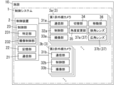
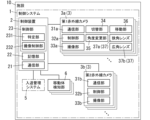
- FIG. 1 is a block diagram showing a configuration of a control system according to the first embodiment.
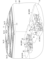
- FIG. 2 is a schematic diagram showing an example of a space in which the above control system is used.
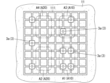
- FIG. 3 is a schematic diagram showing an example of the arrangement of infrared cameras in the control system.
- FIG. 4 is a schematic diagram showing another example of the arrangement of the infrared camera.
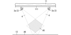
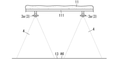
- FIG. 5 is a schematic diagram showing an example of an imaging range of the infrared camera.
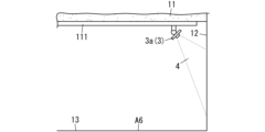
- FIG. 6 is a schematic diagram showing another example of the imaging range of the infrared camera.
- FIG. 7 is a schematic diagram showing still another example of the imaging range of the infrared camera.
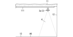
- FIG. 8 is a schematic diagram showing still another example of the imaging range of the infrared camera.
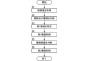
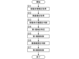
- FIG. 9 is a flowchart showing the operation of the control system.
- FIG. 10 is a block diagram showing the configuration of a control system according to the second embodiment.
- FIG. 11 is a flow
- the control system 1 is installed in a facility 10.
- the term "facility” includes residential facilities used for residential purposes, as well as non-residential facilities such as stores (tenants), offices (office buildings), welfare facilities, educational facilities, hospitals, and factories. Non-residential facilities also include restaurants, amusement parks, hotels, inns, kindergartens, nurseries, and community centers.
- the facility 10 may be a residential facility such as an apartment building, or a non-residential facility such as an office.
- the facility 10 also includes facilities in which residential and non-residential facilities are mixed, for example, with stores on the lower floors and residences on the upper floors. In the first embodiment, it is assumed that the facility 10 is an office.
- the control system 1 includes a determination unit 231 and an imaging control unit 232.
- the identification unit 231 identifies a first area A10 (see FIG. 2) where moving objects such as people H1 (see FIG. 2) are concentrated, based on a thermal image generated by an infrared camera 3 installed in the facility 10.
- moving objects such as people H1 (see FIG. 2) are concentrated, based on a thermal image generated by an infrared camera 3 installed in the facility 10.
- "moving objects are concentrated” does not only include the presence of multiple moving objects in a certain area, but can also include the presence of a single moving object in a certain area.
- the imaging control unit 232 controls the operation of the infrared camera 3.
- the imaging control unit 232 controls the infrared camera 3 so that the first area A10 is imaged preferentially compared to the second area A20 (see FIG. 2) other than the first area A10.
- the control system 1 of the first embodiment is installed in a facility 10, which is an office.
- the control system 1 includes a control device 2 and a plurality of infrared cameras 3.
- the plurality of infrared cameras 3 includes a plurality of first infrared cameras 3a and a plurality of second infrared cameras 3b.
- each of the first infrared camera 3a and the second infrared camera 3b may be simply referred to as an "infrared camera 3.”
- the infrared camera 3 of the first embodiment is directly or indirectly installed on construction materials such as a ceiling surface 11 of the facility 10.
- a plurality of first infrared cameras 3a (nine in the examples of Figs. 3 and 4) and one second infrared camera 3b installed on the ceiling surface 11 of a space Sp1 (room) in the facility 10 will be described.
- the first infrared camera 3a is configured to be able to move, etc., as described below, in order to accurately detect (image) a person H1 present in the facility 10.
- the second infrared camera 3b is configured to be able to image substantially the entire space Sp1.
- the second infrared camera 3b is installed in the center of the ceiling surface 11 of the space Sp1 of the facility 10.
- the second infrared camera 3b includes a communication unit 31b, a control unit 32b, and an imaging unit 33b.
- the communication unit 31b includes a communication interface configured to be capable of communicating with the communication unit 21 of the control device 2, which will be described later.
- “capable of communication” means that information can be exchanged directly or indirectly via a network or a repeater, etc., using an appropriate communication method such as wired communication or wireless communication.
- the communication unit 31b transmits the thermal image generated by the imaging unit 33b to the control device 2.
- the control unit 32b controls the imaging unit 33b.
- the control unit 32b controls the imaging unit 33b based on the control of the imaging control unit 232 of the control device 2.
- the imaging unit 33b detects infrared rays and generates a two-dimensional thermal image.
- the imaging unit 33b has a thermal image imaging element.
- thermal image refers to thermal imaging data, and may include still images (frames), videos, and frame-by-frame thermal images. In the first embodiment, it is assumed that the thermal image acquired by the imaging unit 33b is a video including multiple frames.
- the thermal image generated by the imaging unit 33b has pixels with different display colors depending on the surface temperature of the object. For example, in the thermal image generated by the imaging unit 33b, pixels in areas with higher surface temperatures are displayed in a color closer to white, and pixels in areas with lower surface temperatures are displayed in a color closer to black.
- the second infrared camera 3b is equipped with a lens capable of capturing an image of a relatively wide range, such as a fisheye lens and a compound lens made up of multiple lenses with different optical axis orientations.
- the second infrared camera 3b of the first embodiment is equipped with a fisheye lens and is configured to capture an image of substantially the entire floor 13 (see FIG. 2) of the space Sp1 of the facility 10.
- the first infrared cameras 3a are attached to rails 111 installed on the ceiling surface 11 of the space Sp1 of the facility 10.
- the rails 111 are formed in a lattice pattern and are formed over substantially the entire area of the ceiling surface 11.
- the first infrared cameras 3a of embodiment 1 are installed scattered at substantially equal distances from each other, as shown in FIG. 3, for example.
- each of the first infrared cameras 3a of embodiment 1 is positioned such that its imaging range 4 (see FIG. 5) falls within the imaging range 4 of the second infrared camera 3b.
- the imaging range 4 of each first infrared camera 3a is part of the imaging range 4 of the second infrared camera 3b.
- the first infrared camera 3a includes a communication unit 31a, a control unit 32a, an imaging unit 33a, a switching unit 34, an angle change unit 35, a moving unit 36, and a number of lenses 37.
- the communication unit 31a includes a communication interface configured to be able to communicate with the communication unit 21 of the control device 2.
- the communication unit 31a transmits the thermal image generated by the imaging unit 33a to the control device 2.
- the control unit 32a controls the imaging unit 33a, the switching unit 34, the angle change unit 35, and the movement unit 36.
- the control unit 32a in the first embodiment controls the imaging unit 33a, the switching unit 34, the angle change unit 35, and the movement unit 36 based on the control of the imaging control unit 232 of the control device 2.
- the imaging unit 33a detects infrared rays and generates a two-dimensional thermal image.
- the imaging unit 33a has a thermal image imaging element. In the first embodiment, it is assumed that the thermal image acquired by the imaging unit 33a is a video including multiple frames.
- the thermal image generated by the imaging unit 33a has different pixel display colors depending on the surface temperature of the object. For example, in the thermal image generated by the imaging unit 33a, pixels in areas with higher surface temperatures are displayed in a color closer to white, and pixels in areas with lower surface temperatures are displayed in a color closer to black.
- the multiple lenses 37 include a narrow-angle lens 37a and a wide-angle lens 37b.
- the multiple lenses 37 include multiple types of lenses 37.
- each of the narrow-angle lens 37a and the wide-angle lens 37b may be simply referred to as a "lens 37.”
- the narrow-angle lens 37a has a narrower imaging range 4 and a longer imaging distance than the wide-angle lens 37b.
- the wide-angle lens 37b has a wider imaging range 4 and a shorter imaging distance than the narrow-angle lens 37a.
- the multiple lenses 37 may include other types of lenses 37 in addition to the narrow-angle lens 37a and the wide-angle lens 37b.
- the imaging range 4 of the first infrared camera 3a in embodiment 1 is narrower than the imaging range 4 of the second infrared camera 3b, even when the wide-angle lens 37b is used (attached).
- the switching unit 34 is configured to be able to switch between multiple types of lenses 37. That is, the switching unit 34 in the first embodiment switches between at least the narrow-angle lens 37a and the wide-angle lens 37b. The switching unit 34 also switches between the multiple types of lenses 37 based on the control by the imaging control unit 232 of the control device 2.
- the angle change unit 35 is configured to be able to change the imaging angle of the first infrared camera 3a. More specifically, the angle change unit 35 is configured to be able to rotate (swivel) the first infrared camera 3a in at least one of the horizontal direction (pan direction) and the vertical direction (tilt direction). The angle change unit 35 of the first embodiment is configured to be able to rotate (swivel) the first infrared camera 3a in both the horizontal direction (pan direction) and the vertical direction (tilt direction). In addition, the angle change unit 35 changes the imaging angle based on the control by the imaging control unit 232 of the control device 2.
- the moving unit 36 is configured to enable the first infrared camera 3a to move along the rail 111.
- the moving unit 36 in the first embodiment has, for example, a motor and wheels that are driven by the motor and can change direction.
- the moving unit 36 in the first embodiment is configured to enable the first infrared camera 3a to travel and move along the rail 111.
- the moving unit 36 moves along the rail 111 based on the control by the imaging control unit 232 of the control device 2.
- the control device 2 mainly comprises a computer system having one or more processors and one or more memories.
- the one or more processors execute programs recorded in the memory, thereby realizing the functions of each part of the control device 2.
- the programs may be pre-recorded in the memory, may be provided via a telecommunication line such as the Internet, or may be provided by recording them on a non-transitory recording medium such as a memory card.
- the control device 2 is installed, for example, in a management office of an office building.
- the control device 2 is realized, for example, by a server device.
- the control device 2 has a communication unit 21, a memory unit 22, and a control unit 23.
- the communication unit 21 includes a communication interface configured to be able to communicate with the communication unit 31a of the first infrared camera 3a and the communication unit 31b of the second infrared camera 3b.
- the communication unit 21 receives thermal images from multiple infrared cameras 3.
- the storage unit 22 is a semiconductor memory such as a ROM (Read Only Memory), a RAM (Random Access Memory), or an EEPROM (Electrically Erasable Programmable Read Only Memory). Note that the storage unit 22 is not limited to a semiconductor memory and may be a hard disk drive or the like.
- the storage unit 22 in embodiment 1 stores map information, priority information, and specific information.
- the map information includes layout information of the rooms (spaces Sp1) in the facility 10, information on the height of the ceiling surface 11, layout information of the walls 12, and layout information of the rails 111.
- the map information also includes information on the infrared cameras 3 placed in each space Sp1.
- the map information is, for example, three-dimensional model data such as BIM (Building Information Modeling) data for the facility 10.
- the priority information is information that associates the type of moving object with a priority order for imaging.
- person H1 has the highest priority order for imaging.
- person H1 has the highest priority as an image capture target (detection target) of the infrared camera 3.
- the specific information is information that associates the type of moving object with the temperature of the moving object, the size of the moving object, etc.
- the specific information associates the type of moving object, "person,” with the general body temperature (surface temperature) and two-dimensional area, etc., of person H1.
- the control unit 23 has a determination unit 231 and an imaging control unit 232.
- the identification unit 231 identifies the first area A10 where people H1 are concentrated, based on the thermal image generated by the infrared camera 3.
- the identification unit 231 performs object (moving body) detection processing, such as difference detection processing, on the acquired thermal image.
- the difference detection processing is, for example, processing to detect a moving body (object) using background difference, or processing to detect a moving body by deriving the amount of movement of the moving body using inter-frame difference.
- the identification unit 231 detects a predetermined number of people H1 (moving objects) or more within a predetermined range of area, it identifies that area as a first area A10.
- the identification unit 231 of the first embodiment also identifies the type of the detected moving object. For example, the identification unit 231 identifies the type of the moving object based on the number of pixels included in the detected object (the size of the detected object), the temperature of the pixels, and the identification information.
- the identification unit 231 may detect an object (moving body) and identify the type of moving body using a trained model generated by machine learning.
- the trained model is generated, for example, by supervised learning using multiple pieces of training data.
- the multiple pieces of training data are, for example, multiple thermal images capturing a situation in which a person H1 is present within the imaging range 4.
- the identification unit 231 can obtain, as the output of the trained model, information as to whether or not a person H1 is present within the imaging range 4 (thermal image).
- the machine learning algorithm is, for example, a neural network.
- the identification unit 231 of the first embodiment identifies the first area A10 in which the type of moving object with the highest priority is concentrated, based on the priority information and the thermal image.
- the moving object with the highest priority is a "person.”
- the control system 1 of the first embodiment it is possible to identify the first area A10 in which people H1 (moving objects) that should be imaged (detected) with priority are concentrated.
- the identification unit 231 of the first embodiment also identifies the first area A10 based on a thermal image generated by the second infrared camera 3b. Since the identification unit 231 identifies the first area A10 based on a thermal image generated by the second infrared camera 3b, which has a wider imaging range 4 than the first infrared camera 3a, it is possible to identify the first area A10 with greater accuracy.
- the identification unit 231 of the first embodiment also estimates the destination of a moving object such as person H1 based on the change over time in the thermal image.
- the identification unit 231 estimates the destination of a moving object such as person H1 by, for example, determining the moving direction and moving speed of the image of person H1 detected from the thermal image.
- the identification unit 231 then identifies the first area A10 based on the thermal image and the estimated destination of the moving object. By predicting the destination of a moving object such as person H1, the first area A10 can be identified with greater accuracy.
- the identification unit 231 of the first embodiment also identifies the multiple imaging ranges 4 of the multiple first infrared cameras 3a based on the type, position, and imaging angle of the lenses 37 of the multiple first infrared cameras 3a. Furthermore, the identification unit 231 identifies at least one of the overlapping area A5 (see FIG. 5) where at least two of the identified multiple imaging ranges 4 overlap, and the blank area A6 (see FIG. 5) that is not included in any of the multiple imaging ranges 4.
- the imaging control unit 232 controls the infrared camera 3 to image the first area A10 preferentially compared to the second area A20 other than the first area A10 identified by the identification unit 231.
- the imaging control unit 232 of the first embodiment controls at least one of the multiple infrared cameras 3 to image the first area A10 with priority. More specifically, the imaging control unit 232 controls at least one of the multiple first infrared cameras 3a to image the first area A10 with priority.
- FIG. 3 is a schematic diagram showing an example of the arrangement of multiple first infrared cameras 3a.
- the positions of the multiple first infrared cameras 3a shown in FIG. 3 are default positions. For example, when there is no person H1 (moving object) in the space Sp1, the positions of the multiple first infrared cameras 3a become the default positions. In the default positions, the spacing between the multiple first infrared cameras 3a is approximately equal.
- the identification unit 231 identifies area A1 and area A3 as the first area A10. Other areas such as area A2 and area A4 are the second area A20.
- the imaging control unit 232 controls the first infrared camera 3a to image area A1 and area A3 with priority.
- the imaging control unit 232 controls the first infrared camera 3a to preferentially image areas A1 and A3.
- the imaging control unit 232 moves the first infrared cameras 3a to arrange the multiple first infrared cameras 3a as shown in FIG. 4.
- four first infrared cameras 3a are arranged at positions corresponding to area A1
- two first infrared cameras 3a are arranged at positions corresponding to area A3.
- the imaging control unit 232 moves the first infrared cameras 3a to preferentially image the first area A10, thereby making it possible to image the first area A10 with greater accuracy.
- the imaging control unit 232 may also change the imaging angle of the first infrared camera 3a to preferentially image the first area A10. By changing the imaging angle of the first infrared camera 3a, the imaging control unit 232 can image the first area A10 with greater accuracy.
- the imaging control unit 232 may also change the type of the multiple lenses 37 of the first infrared camera 3a to give priority to imaging the first area A10. For example, the imaging control unit 232 changes from a wide-angle lens 37b to a narrow-angle lens 37a to give priority to imaging the first area A10. By changing the type of the multiple lenses 37 of the first infrared camera 3a, the imaging control unit 232 can more accurately image the first area A10.
- the imaging control unit 232 also controls at least one of the first infrared cameras 3a to reduce at least one of the overlapping area A5 and the blank area A6. More specifically, the imaging control unit 232 controls at least one of the first infrared cameras 3a to change at least one of the type of lens 37, the position of the first infrared camera 3a, and the imaging angle in order to reduce at least one of the overlapping area A5 and the blank area A6.
- the two imaging ranges 4 of the two first infrared cameras 3a overlap to form an overlapping area A5.
- the imaging control unit 232 changes the imaging angles of the two first infrared cameras 3a to reduce the overlapping area A5 and blank area A6, for example, as shown in FIG. 6.
- the imaging control unit 232 also determines whether the imaging range 4 includes areas with low imaging priority, such as the wall 12, based on the imaging range 4 identified by the identification unit 231 and the map information.
- the wall 12 is included in the imaging range 4 of the first infrared camera 3a.
- the imaging control unit 232 determines that the wall 12 is included in the imaging range 4 based on the imaging range 4 identified by the identification unit 231 and the map information.
- the imaging control unit 232 determines that the wall 12 is included in the imaging range 4, it changes the imaging angle of the first infrared camera 3a to reduce areas with low imaging priority and blank areas A6, for example, as shown in FIG. 8.
- the imaging control unit 232 controls the infrared camera 3 to reduce at least one of the overlapping area A5 and the blank area A6, thereby making it possible to image the space Sp1 more holistically (comprehensively).
- the control device 2 acquires a thermal image by receiving the thermal image from the infrared camera 3 (S1). Next, the control device 2 determines (identifies) the type of moving object based on the thermal image and the identification information (S2). Then, the control device 2 identifies the first area A10 based on the thermal image and the priority information (S3).
- control device 2 performs a first imaging control (S4).
- the control device 2 controls the infrared camera 3 to image the first area A10 with priority.
- control device 2 determines (identifies) the multiple imaging ranges 4 of the multiple first infrared cameras 3a based on the type of lens 37 of the multiple first infrared cameras 3a, the position of the first infrared cameras 3a, and the imaging angle (S5).
- control device 2 performs a second imaging control (S6).
- the control device 2 controls the infrared camera 3 to reduce at least one of the overlapping area A5 and the blank area A6.
- control device 2 Functions equivalent to the control system 1 (control device 2) according to embodiment 1 may be embodied in a control method, a (computer) program, or a non-transitory recording medium on which a program is recorded, etc.
- the control method according to one aspect is executed by a computer system.
- the control method has an identifying step and a control step.
- a first area A10 in which moving objects are concentrated is identified based on a thermal image generated by an infrared camera 3 installed in the facility 10.
- the operation of the infrared camera 3 is controlled.
- the infrared camera 3 is controlled so that the first area A10 is imaged preferentially compared to a second area A20 other than the first area A10.
- the program according to one aspect is a program for causing one or more processors to execute the above control method.
- the executing entity of the control system 1 or the control method in the present disclosure includes a computer system.
- the computer system is mainly composed of a processor and a memory as hardware.
- the function of the executing entity of the control system 1 or the control method in the present disclosure is realized by the processor executing a program recorded in the memory of the computer system.
- the program may be pre-recorded in the memory of the computer system, may be provided through a telecommunication line, or may be recorded and provided on a non-transitory recording medium such as a memory card, an optical disk, or a hard disk drive that can be read by the computer system.
- the processor of the computer system is composed of one or more electronic circuits including a semiconductor integrated circuit (IC) or a large scale integrated circuit (LSI).
- the integrated circuits such as ICs or LSIs referred to here are called different names depending on the degree of integration, and include integrated circuits called system LSIs, VLSIs (Very Large Scale Integration), or ULSIs (Ultra Large Scale Integration).
- a field-programmable gate array (FPGA) that is programmed after the LSI is manufactured, or a logic device that allows the reconfiguration of the connection relationships within the LSI or the reconfiguration of the circuit partitions within the LSI, can also be used as a processor.
- FPGA field-programmable gate array
- Multiple electronic circuits may be integrated into one chip, or may be distributed across multiple chips. Multiple chips may be integrated into one device, or may be distributed across multiple devices.
- the computer system referred to here includes a microcontroller having one or more processors and one or more memories.
- the microcontroller is also composed of one or more electronic circuits including a semiconductor integrated circuit or a large-scale integrated circuit.
- control system 1 it is not essential for the control system 1 that multiple functions are concentrated in one housing, and the components of the control system 1 may be distributed across multiple housings. Furthermore, at least some of the functions of the control system 1, for example, some of the functions of the control device 2, may be realized by the cloud (cloud computing) or the like.
- control system 1 at least some of the functions of the control system 1 that are distributed among multiple devices may be consolidated within a single housing.
- control device 2 and the infrared camera 3 may be consolidated within a single housing.
- the control system 1 only needs to include at least the identification unit 231 and the imaging control unit 232.
- the first embodiment illustrates a case in which the control system 1 includes multiple infrared cameras 3, the control system 1 may include only one infrared camera 3.
- control device 2 is installed inside the facility 10, but the control device 2 may be installed outside the facility 10. In other words, a part of the control system 1 may be provided outside the facility 10.
- the machine learning algorithm is a neural network
- the machine learning algorithm is not limited to a neural network, and may be, for example, eXtreme Gradient Boosting (XGB) regression, Random Forest, decision tree, Logistic Regression, Support Vector Machine (SVM), Naive Bayes classifier, k-nearest neighbors, etc.
- the machine learning algorithm may be, for example, a Gaussian Mixture Model (GMM), k-means clustering, etc.
- GMM Gaussian Mixture Model
- a trained model may be updated by performing additional training.
- the identification unit 231 identifies the first area A10 based on the thermal image generated by the second infrared camera 3b. However, it is not essential that the control system 1 includes the second infrared camera 3b. In other words, the identification unit 231 may identify the first area A10 based on the thermal image generated by the first infrared camera 3a.
- control system 1 according to the second embodiment differs from the control system 1 according to the first embodiment in that the control system 1 according to the second embodiment further includes an entrance/exit management system 5 and a plurality of mobile object detection units 6.
- the entrance/exit control system 5 is a system that manages entry and exit to rooms (space Sp1) within the facility 10.
- person H1 holds an authentication card he or she carries over an authentication device installed in front of the door of each room (space Sp1), and if authentication is successful, the door is automatically unlocked.
- the entrance/exit management system 5 makes it possible to manage the behavior of person H1 (such as when and where they were) based on the authentication record. For example, the entrance/exit management system 5 makes it possible to manage the number of people H1 present in each space Sp1.
- the entrance/exit management system 5 transmits entrance/exit information, including the entrance/exit history of people H1 (mobiles) within the facility 10, to the control device 2.
- the entrance/exit management information includes information indicating the number of people H1 present in each space Sp1.
- the moving object detection unit 6 is a sensor installed in the facility 10 that detects moving objects such as person H1.
- the moving object detection unit 6 is a seating sensor provided on each chair in the space Sp1.
- the moving object detection unit 6 transmits detection information indicating whether person H1 is sitting in a chair to the control device 2.
- the identification unit 231 of the second embodiment identifies the first area A10 based on the entrance/exit information and thermal images received from the entrance/exit management system 5. Since the first area A10 is identified using the entrance/exit information of the person H1 (moving object), it is possible to grasp the number of people H1 present in the space Sp1, and to identify the first area A10 with greater accuracy.
- the identification unit 231 of the second embodiment identifies the first area A10 based on the detection information and thermal image received from the moving object detection unit 6. Since the first area A10 is identified using moving object detection information, such as whether or not the person H1 is sitting in a chair, the first area A10 can be identified with greater accuracy.
- the control device 2 acquires mobile object information (S1).
- the mobile object information includes at least one of entrance/exit management information and detection information.
- the control device 2 of the second embodiment acquires entrance/exit management information as mobile object information from the entrance/exit management system 5, and acquires detection information as mobile object information from the mobile object detection unit 6. After acquiring the mobile object information, the control device 2 identifies the first area A10 based on the thermal image, the mobile object information, and the priority information (S14).
- steps S12 to S13 and steps S15 to S17 are similar to the processes in steps S1 to S2 and steps S4 to S6 described in embodiment 1, and therefore will not be described here.
- control system 1 includes the entrance/exit management system 5, but the control system 1 does not have to include the entrance/exit management system 5.
- control system 1 and the entrance/exit management system 5 may be separate systems.
- the control system (1) includes an identification unit (231) and an imaging control unit (232).
- the identification unit (231) identifies a first area (A10) where moving objects are concentrated, based on a thermal image generated by an infrared camera (3) installed in a facility (10).
- the imaging control unit (232) controls the operation of the infrared camera (3).
- the imaging control unit (232) controls the infrared camera (3) to image the first area (A10) preferentially compared to a second area (A20) other than the first area (A10).
- the infrared camera (3) preferentially captures an image of the first area (A10) where moving objects such as people (H1) that are to be detected are concentrated, thereby improving the detection accuracy of moving objects such as people (H1).
- the identification unit (231) estimates the destination of the moving object based on the change over time in the thermal image.
- the identification unit (231) identifies a first area (A10) based on the thermal image and the estimation of the destination of the moving object.
- the imaging control unit (232) controls at least one of the plurality of infrared cameras (3) to image the first area (A10) preferentially compared to a second area (A20) other than the first area (A10).
- the first area (A10) can be identified with greater accuracy by predicting the destination of the moving object.
- the plurality of infrared cameras (3) include a first infrared camera (3a) and a second infrared camera (3b).
- the imaging range (4) of the first infrared camera (3a) is a part of the imaging range (4) of the second infrared camera (3b).
- the identification unit (231) identifies the first area (A10) based on the thermal image generated by the second infrared camera (3b).
- the imaging control unit (232) controls the first infrared camera (3a) to preferentially image the first area (A10).
- the first area (A10) is identified based on a thermal image generated by the second infrared camera (3b) that has a relatively wide imaging range (4), so the first area (A10) can be identified with greater accuracy.
- the identification unit (231) identifies the first area (A10) based on the thermal image and on entry/exit information including the entry/exit history of moving objects within the facility (10).
- the first area (A10) is identified using the entry and exit information of moving objects, so that the number of moving objects present in the space (Sp1) can be ascertained, and the first area (A10) can be identified with greater accuracy.
- a mobile object detection unit (6) that detects the presence of a mobile object is installed in the facility (10).
- the identification unit (231) identifies the first area (A10) based on the detection information of the mobile object by the mobile object detection unit (6) and the thermal image.
- the first area (A10) is identified using detection information of the moving body, so that the first area (A10) can be identified with greater accuracy.
- any one of the first to fifth aspects there are a plurality of infrared cameras (3).
- the plurality of infrared cameras (3) are installed in the same space (Sp1) of the facility (10).
- the identification unit (231) identifies a plurality of imaging ranges (4) of the plurality of infrared cameras (3) based on the type, position, and imaging angle of the lens (37) of the plurality of infrared cameras (3).
- the identification unit (231) identifies at least one of an overlapping area (A5) where at least two of the plurality of imaging ranges (4) overlap, and a blank area (A6) that is not included in any of the plurality of imaging ranges (4).
- the imaging control unit (232) controls at least one of the plurality of infrared cameras (3) to change at least one of the type, position, and imaging angle of the lens (37) so as to reduce at least one of the overlapping area (A5) and the blank area (A6).
- the identification unit (231) identifies the type of moving object based on the thermal image.
- the identification unit (231) identifies the first area (A10) in which the type of moving object with the highest priority is concentrated based on the thermal image and priority information that associates the type of moving object with the priority of image capture.
- control system (1) according to the eighth aspect further includes an infrared camera (3) in any one of the first to seventh aspects.
- the infrared camera (3) has a plurality of lenses (37) and a switching unit (34).
- the plurality of lenses (37) includes a narrow-angle lens (37a) and a wide-angle lens (37b).
- the switching unit (34) switches between the plurality of types of lenses (37).
- the switching unit (34) switches between the plurality of types of lenses (37) based on the control by the imaging control unit (232).
- the infrared camera (3) has an angle change unit (35) that changes the imaging angle.
- the angle change unit (35) changes the imaging angle based on the control by the imaging control unit (232).
- the imaging angle of the infrared camera (3) can be changed to capture an image of the first area (A10) with greater accuracy.
- the infrared camera (3) is attached to a rail (111) installed on the ceiling surface (11) of the facility (10).
- the infrared camera (3) has a moving unit (36) configured to allow the infrared camera (3) to move along the rail (111).
- the moving unit (36) moves along the rail (111) based on the control of the imaging control unit (232).
- the first area (A10) can be imaged more accurately by moving the infrared camera (3).
- Configurations other than the first aspect are not essential to the control system (1) and may be omitted as appropriate.
- the control method according to the twelfth aspect is executed by a computer system.
- the control method has an identification step and a control step.
- a first area (A10) where moving objects are concentrated is identified based on a thermal image generated by an infrared camera (3) installed in the facility (10).
- the operation of the infrared camera (3) is controlled.
- the infrared camera (3) is controlled so as to preferentially image the first area (A10) compared to a second area (A20) other than the first area (A10).
- the infrared camera (3) preferentially captures an image of the first area (A10) where moving objects such as people (H1) that are to be detected are concentrated, thereby improving the detection accuracy of moving objects such as people (H1).
- the program according to the thirteenth aspect is a program for causing a computer system to execute the control method according to the twelfth aspect.
- the infrared camera (3) prioritizes imaging of the first area (A10) where moving objects such as people (H1) that are to be detected are concentrated, thereby improving the detection accuracy of moving objects such as people (H1).
- Control system 10 Facilities 11 Ceiling surface 111 Rail 231 Identification unit 232 Imaging control unit 3 Infrared camera 3a First infrared camera 3b Second infrared camera 34 Switching unit 35 Angle change unit 36 Movement unit 37 Lens 37a Narrow angle lens 37b Wide angle lens 4 Imaging range 6 Mobile object detection unit A10 First area A20 Second area A5 Overlapping area A6 Blank area Sp1 Space
Landscapes
- Engineering & Computer Science (AREA)
- Multimedia (AREA)
- Physics & Mathematics (AREA)
- General Physics & Mathematics (AREA)
- Signal Processing (AREA)
- Theoretical Computer Science (AREA)
- Spectroscopy & Molecular Physics (AREA)
- Studio Devices (AREA)
Priority Applications (2)
| Application Number | Priority Date | Filing Date | Title |
|---|---|---|---|
| JP2024565767A JPWO2024135342A1 (cg-RX-API-DMAC7.html) | 2022-12-20 | 2023-12-05 | |
| EP23906708.5A EP4641151A4 (en) | 2022-12-20 | 2023-12-05 | Control system, control method, and program |
Applications Claiming Priority (2)
| Application Number | Priority Date | Filing Date | Title |
|---|---|---|---|
| JP2022-203563 | 2022-12-20 | ||
| JP2022203563 | 2022-12-20 |
Publications (1)
| Publication Number | Publication Date |
|---|---|
| WO2024135342A1 true WO2024135342A1 (ja) | 2024-06-27 |
Family
ID=91588457
Family Applications (1)
| Application Number | Title | Priority Date | Filing Date |
|---|---|---|---|
| PCT/JP2023/043434 Ceased WO2024135342A1 (ja) | 2022-12-20 | 2023-12-05 | 制御システム、制御方法及びプログラム |
Country Status (3)
| Country | Link |
|---|---|
| EP (1) | EP4641151A4 (cg-RX-API-DMAC7.html) |
| JP (1) | JPWO2024135342A1 (cg-RX-API-DMAC7.html) |
| WO (1) | WO2024135342A1 (cg-RX-API-DMAC7.html) |
Citations (9)
| Publication number | Priority date | Publication date | Assignee | Title |
|---|---|---|---|---|
| JP2015178953A (ja) | 2013-05-17 | 2015-10-08 | パナソニック インテレクチュアル プロパティ コーポレーション オブアメリカPanasonic Intellectual Property Corporation of America | センサー搭載装置 |
| JP2018067755A (ja) * | 2016-10-17 | 2018-04-26 | シャープ株式会社 | 検出データ管理装置 |
| JP2018200252A (ja) * | 2017-05-29 | 2018-12-20 | アズビル株式会社 | 熱画像処理装置およびオフセット量算出方法 |
| JP2018204921A (ja) * | 2017-06-09 | 2018-12-27 | アズビル株式会社 | 人検知装置および方法 |
| WO2019221244A1 (ja) * | 2018-05-16 | 2019-11-21 | パナソニックIpマネジメント株式会社 | 物体検知システム、センサシステム、空気調和システム、物体検知方法及びプログラム |
| US20200064784A1 (en) * | 2018-08-24 | 2020-02-27 | Lutron Technology Company Llc | Occupant detection device |
| JP2020079784A (ja) * | 2014-03-03 | 2020-05-28 | パナソニック インテレクチュアル プロパティ コーポレーション オブ アメリカPanasonic Intellectual Property Corporation of America | 熱画像処理方法および熱画像処理装置 |
| JP2021145792A (ja) * | 2020-03-17 | 2021-09-27 | 株式会社リコー | 情報処理装置、情報処理システム、情報処理方法、及びプログラム |
| WO2022130513A1 (ja) * | 2020-12-15 | 2022-06-23 | 三菱電機株式会社 | 識別装置、設備機器システム及び識別方法 |
Family Cites Families (4)
| Publication number | Priority date | Publication date | Assignee | Title |
|---|---|---|---|---|
| CN211978126U (zh) * | 2020-05-13 | 2020-11-20 | 新疆爱华盈通信息技术有限公司 | 热成像阵列及体温监测装置 |
| WO2021240570A1 (ja) * | 2020-05-25 | 2021-12-02 | 三菱電機株式会社 | 空調制御システム、コントローラおよび空調制御方法 |
| JP2022114076A (ja) * | 2021-01-26 | 2022-08-05 | 株式会社Jvcケンウッド | カメラシステム、追跡方法、及び追跡プログラム |
| KR102411612B1 (ko) * | 2022-02-04 | 2022-06-22 | 주식회사 월드씨엔에스 | 다수의 카메라를 이용한 열화상 감시 시스템 |
-
2023
- 2023-12-05 JP JP2024565767A patent/JPWO2024135342A1/ja active Pending
- 2023-12-05 WO PCT/JP2023/043434 patent/WO2024135342A1/ja not_active Ceased
- 2023-12-05 EP EP23906708.5A patent/EP4641151A4/en active Pending
Patent Citations (9)
| Publication number | Priority date | Publication date | Assignee | Title |
|---|---|---|---|---|
| JP2015178953A (ja) | 2013-05-17 | 2015-10-08 | パナソニック インテレクチュアル プロパティ コーポレーション オブアメリカPanasonic Intellectual Property Corporation of America | センサー搭載装置 |
| JP2020079784A (ja) * | 2014-03-03 | 2020-05-28 | パナソニック インテレクチュアル プロパティ コーポレーション オブ アメリカPanasonic Intellectual Property Corporation of America | 熱画像処理方法および熱画像処理装置 |
| JP2018067755A (ja) * | 2016-10-17 | 2018-04-26 | シャープ株式会社 | 検出データ管理装置 |
| JP2018200252A (ja) * | 2017-05-29 | 2018-12-20 | アズビル株式会社 | 熱画像処理装置およびオフセット量算出方法 |
| JP2018204921A (ja) * | 2017-06-09 | 2018-12-27 | アズビル株式会社 | 人検知装置および方法 |
| WO2019221244A1 (ja) * | 2018-05-16 | 2019-11-21 | パナソニックIpマネジメント株式会社 | 物体検知システム、センサシステム、空気調和システム、物体検知方法及びプログラム |
| US20200064784A1 (en) * | 2018-08-24 | 2020-02-27 | Lutron Technology Company Llc | Occupant detection device |
| JP2021145792A (ja) * | 2020-03-17 | 2021-09-27 | 株式会社リコー | 情報処理装置、情報処理システム、情報処理方法、及びプログラム |
| WO2022130513A1 (ja) * | 2020-12-15 | 2022-06-23 | 三菱電機株式会社 | 識別装置、設備機器システム及び識別方法 |
Non-Patent Citations (1)
| Title |
|---|
| See also references of EP4641151A1 |
Also Published As
| Publication number | Publication date |
|---|---|
| EP4641151A4 (en) | 2026-03-04 |
| JPWO2024135342A1 (cg-RX-API-DMAC7.html) | 2024-06-27 |
| EP4641151A1 (en) | 2025-10-29 |
Similar Documents
| Publication | Publication Date | Title |
|---|---|---|
| EP3985611B1 (en) | Building radar-camera surveillance system | |
| US11645781B2 (en) | Automated determination of acquisition locations of acquired building images based on determined surrounding room data | |
| US11790648B2 (en) | Automated usability assessment of buildings using visual data of captured in-room images | |
| US11610238B1 (en) | System and method for collecting and managing property information | |
| US11537749B2 (en) | Privacy protection in mobile robot | |
| Mikkilineni et al. | A novel occupancy detection solution using low-power IR-FPA based wireless occupancy sensor | |
| CN105245850B (zh) | 跨监控摄像头进行目标追踪的方法、装置和系统 | |
| US11600063B1 (en) | Guided inspection system and method | |
| US8334906B2 (en) | Video imagery-based sensor | |
| US20100103266A1 (en) | Method, device and computer program for the self-calibration of a surveillance camera | |
| JP5956248B2 (ja) | 画像監視装置 | |
| US20040125207A1 (en) | Robust stereo-driven video-based surveillance | |
| US20050012817A1 (en) | Selective surveillance system with active sensor management policies | |
| JP2019508665A (ja) | 半自律的モバイルロボットのナビゲーティング | |
| Fichtner et al. | Semantic enrichment of octree structured point clouds for multi‐story 3D pathfinding | |
| Huang et al. | Video arrays for real-time tracking of person, head, and face in an intelligent room | |
| US10565786B1 (en) | Sensor placement interface | |
| Wang et al. | An intelligent surveillance system based on an omnidirectional vision sensor | |
| US20240312136A1 (en) | Automated Generation Of Building Floor Plans Having Associated Absolute Locations Using Multiple Data Capture Devices | |
| US10643078B2 (en) | Automatic camera ground plane calibration method and system | |
| JP2024133230A (ja) | 情報処理装置、システム、情報処理方法、及びプログラム | |
| WO2018156275A1 (en) | Occupant position tracking using imaging sensors | |
| Conci et al. | Camera placement using particle swarm optimization in visual surveillance applications | |
| JPWO2020003818A1 (ja) | 検査装置及び検査方法 | |
| EP4641151A1 (en) | Control system, control method, and program |
Legal Events
| Date | Code | Title | Description |
|---|---|---|---|
| 121 | Ep: the epo has been informed by wipo that ep was designated in this application |
Ref document number: 23906708 Country of ref document: EP Kind code of ref document: A1 |
|
| WWE | Wipo information: entry into national phase |
Ref document number: 2024565767 Country of ref document: JP |
|
| WWE | Wipo information: entry into national phase |
Ref document number: 2023906708 Country of ref document: EP |
|
| NENP | Non-entry into the national phase |
Ref country code: DE |
|
| ENP | Entry into the national phase |
Ref document number: 2023906708 Country of ref document: EP Effective date: 20250721 |
|
| ENP | Entry into the national phase |
Ref document number: 2023906708 Country of ref document: EP Effective date: 20250721 |
|
| ENP | Entry into the national phase |
Ref document number: 2023906708 Country of ref document: EP Effective date: 20250721 |
|
| WWP | Wipo information: published in national office |
Ref document number: 2023906708 Country of ref document: EP |