WO2024134875A1 - レール - Google Patents
レール Download PDFInfo
- Publication number
- WO2024134875A1 WO2024134875A1 PCT/JP2022/047622 JP2022047622W WO2024134875A1 WO 2024134875 A1 WO2024134875 A1 WO 2024134875A1 JP 2022047622 W JP2022047622 W JP 2022047622W WO 2024134875 A1 WO2024134875 A1 WO 2024134875A1
- Authority
- WO
- WIPO (PCT)
- Prior art keywords
- rail
- head
- temperature
- pearlite structure
- fatigue damage
- Prior art date
- Legal status (The legal status is an assumption and is not a legal conclusion. Google has not performed a legal analysis and makes no representation as to the accuracy of the status listed.)
- Ceased
Links
Images


Classifications
-
- C—CHEMISTRY; METALLURGY
- C22—METALLURGY; FERROUS OR NON-FERROUS ALLOYS; TREATMENT OF ALLOYS OR NON-FERROUS METALS
- C22C—ALLOYS
- C22C38/00—Ferrous alloys, e.g. steel alloys
-
- C—CHEMISTRY; METALLURGY
- C22—METALLURGY; FERROUS OR NON-FERROUS ALLOYS; TREATMENT OF ALLOYS OR NON-FERROUS METALS
- C22C—ALLOYS
- C22C38/00—Ferrous alloys, e.g. steel alloys
- C22C38/18—Ferrous alloys, e.g. steel alloys containing chromium
- C22C38/40—Ferrous alloys, e.g. steel alloys containing chromium with nickel
- C22C38/58—Ferrous alloys, e.g. steel alloys containing chromium with nickel with more than 1.5% by weight of manganese
-
- C—CHEMISTRY; METALLURGY
- C21—METALLURGY OF IRON
- C21D—MODIFYING THE PHYSICAL STRUCTURE OF FERROUS METALS; GENERAL DEVICES FOR HEAT TREATMENT OF FERROUS OR NON-FERROUS METALS OR ALLOYS; MAKING METAL MALLEABLE, e.g. BY DECARBURISATION OR TEMPERING
- C21D8/00—Modifying the physical properties of ferrous metals or ferrous alloys by deformation combined with, or followed by, heat treatment
Definitions
- the present invention relates to rails.
- high-strength rails have been proposed, for example, as shown in Patent Documents 1, 2, 3, and 4.
- the main feature of these rails is that in addition to improving wear resistance, they improve resistance to internal fatigue damage by either adding a small amount of alloy to control pearlite transformation, or by controlling the alloy or adding a small amount of alloy to form precipitates in the pearlite structure, thereby improving the hardness inside the head.
- Patent Document 1 discloses that by adding B to hypereutectoid steel (C: over 0.85% to 1.20%), the transformation temperature of the pearlite structure inside the head is controlled, thereby improving the hardness inside the head.
- Patent Document 2 discloses that the hardness inside the head is improved by adding V and N to hypereutectoid steel (C: over 0.85% to 1.20%) and precipitating V carbonitrides in the pearlite structure.
- Patent document 3 also discloses that the hardness inside the head is improved by controlling the Mn and Cr content using eutectoid steel (C: 0.73-0.85%) as a base.
- Patent Document 4 discloses that V is added to steel with C: 0.75-1.20% to generate Cr-containing V nitrides in the ferrite in the pearlite structure, thereby improving the internal hardness of the head at a depth of 25 mm from the outer surface of the head.
- Patent Documents 1, 2, 3, and 4 improve the hardness inside the head by controlling the pearlite transformation temperature inside the head and by precipitation strengthening the pearlite structure, and can improve resistance to internal fatigue damage within a certain range.
- Patent Documents 1, 2, 3, and 4 were unable to provide sufficient characteristics for use in track environments where freight cars are increasingly loaded and overcrowded, resulting in greater repeated loads, and further improvement of internal fatigue damage resistance was an issue.
- the present invention was devised in consideration of the above-mentioned problems, and aims to provide rails that are more resistant to internal fatigue damage than existing technologies for use on freight railways, where track environments are subject to even greater repeated loads due to increased loads and overcrowding in recent years.
- the gist of the present invention is as follows:
- a rail according to one embodiment of the present invention has, in mass %, C: 0.75 to 1.20%, Si: 0.10 to 2.00%, Mn: 0.05 to 2.00%, Cr: 0.05 to 2.00%, V: 0.005 to 0.100%, Al: 0.0010 to 1.0000%, N: 0.006 to 0.020%, P ⁇ 0.025%, S ⁇ 0.025%, Mo: 0 to 0.50%, Co: 0 to 1.00%, B: 0 to 0.0050%, Cu: 0 to 1.00%, Ni: 0 to 1.00%, Nb: 0 to 0.0500%, Ti: 0 to 0.0500%, Mg: 0 to 0.0200%, Ca: 0 to 0.50%, and Mn: 0 to 0.50%.
- the rail has a metal structure at a depth of 25 mm from the head outer surface, the metal structure contains a pearlite structure with an area ratio of 95% or more, the hardness of the rail measured at the position 25 mm deep from the head outer surface is in the range of Hv 360 to 500, and the number density of nitrides containing Cr, Mn and V with a grain size of 0.5 to 6.0 nm in the ferrite phase in the pearlite structure at the position 25 mm deep from the head outer surface is 1 cm
- the average ratio of the sum of the number of Cr atoms (CA) and the number of Mn atoms (MA) to the number of V atoms (VA) rounded off to one decimal place (CA+MA)/VA) satisfies the following formula
- the rail described in (1) above may contain, in mass%, one or more of the following: Mo: 0.01-0.50%, Co: 0.01-1.00%, B: 0.0001-0.0050%, Cu: 0.01-1.00%, Ni: 0.01-1.00%, Nb: 0.0010-0.0500%, Ti: 0.0030-0.0500%, Mg: 0.0005-0.0200%, Ca: 0.0005-0.0200%, REM: 0.0005-0.0500%, and Zr: 0.0001-0.0200%.
- the above-mentioned aspects of the present invention can improve the resistance of rails to internal fatigue damage. Furthermore, such rails can significantly improve the service life of rails when used in freight railways, where the track environment is subject to greater repeated loads due to heavier loads and greater congestion.
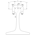
- FIG. 1 shows the head outer surface position (symbol X) where the temperature was measured during rolling and heat treatment in the experiments and examples of this specification, and the position 25 mm deep from the head outer surface (symbol Y) where the metal structure, hardness, and precipitate state were evaluated.
- FIG. 1 is a diagram showing an outline of a rolling fatigue testing machine.
- FIG. 13 is a diagram showing the effect of nitrides containing Cr, Mn, and V on rolling fatigue test results.
- FIG. 1 is a diagram showing the relationship between the number of nitrides containing Cr, Mn, and V and the cumulative passing tonnage at which cracks were initiated.
- FIG. 2 is a diagram showing the designations of rail heads. This is a diagram showing a position 25 mm deep from the head outer surface at the rail head.
- a rail with excellent resistance to internal fatigue damage according to one embodiment of the present invention (sometimes referred to as the rail according to this embodiment) will be described in detail.
- mass% in the composition will simply be written as %.
- the rail according to this embodiment has the following features.
- It has a predetermined chemical composition.
- the metal structure at a depth of 25 mm from the head outer surface contains a pearlite structure with an area ratio of 95% or more, and the hardness of the rail measured at the said position is in the range of Hv 360 to 500.
- the number density of nitrides containing Cr, Mn and V having a grain size of 0.5 to 6.0 nm is in the range of 1.0 x 10 17 to 5.0 x 10 17 per cm 3 .
- a technique capable of improving the internal fatigue damage resistance of rails more than existing techniques involves generating fine nitrides containing the above-mentioned Cr, Mn, and V in the ferrite phase in the pearlite structure at a depth of 25 mm from the head outer surface.
- Pearlite is a layered aggregate of ferrite and cementite formed by the eutectic transformation of austenite.
- the term "ferrite phase in pearlite structure” refers to layered ferrite contained in pearlite.
- the term "ferrite phase in pearlite structure” is a concept that does not include ferrite that does not constitute pearlite, such as pro-eutectoid ferrite. Representative experimental details are described below.
- Heat treatment conditions for controlling each cooling temperature, the temperature measured at the head outer surface position shown in Figure 1 was used) Heat treatment conditions: After rolling, accelerated cooling + controlled cooling Accelerated cooling conditions (head outer surface): Accelerated cooling start temperature 790°C, accelerated cooling end temperature 580°C, and average cooling rate 6°C/sec Controlled cooling conditions (head outer surface): holding temperature 600°C, rail surface temperature fluctuation range during temperature holding 40°C, temperature holding time 80 seconds, followed by accelerated cooling Temperature holding during controlled cooling: Accelerated cooling rate was controlled, and accelerated cooling was repeatedly started and stopped in response to heat recovery from inside the rail, thereby controlling the temperature Metal structure (measured at the position marked with the symbol Y in Figure 1, i.e., a position 25 mm deep from the head outer surface) Pearlite Hardness (measured at a
- the inventive steel rail and the comparative steel rail were evaluated for internal fatigue damage resistance using a rolling fatigue testing machine as shown in Figure 2. Details of the rolling fatigue test conditions and evaluation method are described below. In particular, in recent years, freight railways have become heavier in load and more crowded, leading to greater repeated loads, so in order to reproduce the track environment, the load was set higher than the conventional conditions (see International Publication No. WO2020/054339).
- Test conditions Testing machine Rolling fatigue testing machine (see Figure 2)
- Test piece shape Rail 136 pound rail x 2m Wheels: AAR type (diameter 920 mm)
- Load Radial: 290-340KN
- Thrust 60-90KN (Reproduces the load conditions on tracks with higher loads than before)
- Lubrication Oil lubrication
- Cumulative passing tonnage Until cracks occur (maximum 200 MGT*) *MGT: Million Gloss Tonnage, the total weight of the freight cars running on the rails. In this test, it is evaluated as twice the passing weight acting on the wheels.
- the inventive steel rail has better resistance to internal fatigue damage in the high load range than conventional steel rails, compared to the comparative steel rails.
- nitrides containing Cr, Mn, and V with particle sizes of 0.5 to 6.0 nm in the ferrite phase in the pearlite structure, which suppresses the occurrence of microscopic softened areas in the ferrite in the pearlite structure and homogenizes the material strength within the cross section inside the head.
- concentration of strain in the microscopic softened areas of the ferrite phase inside the head and the occurrence of fatigue cracks that occur when the rail and wheel come into contact are suppressed.
- nitrides containing Cr, Mn and V showed high resistance to internal fatigue damage is thought to be because nitrides containing Cr, Mn and V are more stable against heat and stress than carbides or simple V nitrides, suppressing the microscopic softening of the ferrite phase of the pearlite structure inside the head and steadily improving the hardness of the ferrite phase in the pearlite structure.
- the inventors investigated the formation of nitrides containing Cr, Mn, and V at a depth of 25 mm from the head outer surface in rails that exhibit excellent resistance to internal fatigue damage.
- Heating rate of cast slab 7°C/min within the range of 1000-1200°C End temperature of heating of cast piece: 1260°C
- Rolling conditions rolling temperature was measured at the head outer surface position shown in Figure 1
- Area reduction rate of head outer surface at rolling temperature of 980°C: 18% The rolling conditions for each steel rail were all the same.
- Heat treatment conditions for each cooling temperature control, the temperature measured at the head outer surface position shown in Figure 1 was used
- Accelerated cooling conditions head outer surface: Accelerated cooling start temperature 800°C, accelerated cooling end temperature 580°C, and average cooling rate 5°C/sec
- Controlled cooling conditions head outer surface: Holding temperature 600-660°C, rail surface temperature fluctuation range 20-40°C during temperature holding, temperature holding time 2-180 sec, then accelerated cooling.
- Temperature holding during controlled cooling Accelerated cooling speed was controlled, and accelerated cooling was repeatedly started and stopped to control the temperature according to heat recovery from inside the rail.
- the number of nitrides containing Cr, Mn, and V at a depth of 25 mm from the head outer surface was significantly changed.
- ⁇ Measurement equipment Three-dimensional atom probe (3DAP) method
- 3DAP Three-dimensional atom probe
- a pulse voltage is applied, or a pulse laser is irradiated onto the needle sample, causing the ions of the constituent atoms to be field-evaporated from the tip of the needle.
- These ions are detected by a coordinate detector.
- the type of element is identified by the ion flight time.
- the three-dimensional element position and number of atoms are identified based on the detected coordinates and the measurement order.
- Voltage DC, voltage pulse (pulse ratio 15% or more) or laser pulse (40 pJ)
- Sample temperature 40K to 70K
- the atomic position data of Cr, Mn, V, and N are used to determine whether there are nitride precipitates.
- the Maximum Separation Method included in IVAS is used for this purpose. This is a method in which groups of Cr, Mn, V, and N atoms whose mutual distance is equal to or less than a specific value are separated from the matrix and recognized as precipitates. In this experiment, 1 nm was used as the "specific value.”
- the IVAS software is used to count the number of precipitates in the ferrite phase of the pearlite structure within the measurement area that are determined to be nitrides containing Cr, Mn, and V.
- nitrides containing Cr, Mn, and V are used to strengthen the ferrite phase in the pearlite structure, so in this experiment, only those present in the center of the ferrite phase in the pearlite structure were evaluated.
- the separation of the cementite phase and the ferrite phase in the measurement area can be determined from the C distribution.
- the C concentration is 25% in terms of atomic ratio.
- the volume of the analysis area is estimated from the number of atoms contained in the analysis area measured by 3DAP.
- the amount of alloy elements other than iron is very small, so even if the atoms constituting the analysis area are all assumed to be iron atoms and the volume of the analysis area is calculated from the number of elements in the analysis area, it is considered that there is no significant difference from the true value. Therefore, the number of iron atoms is corrected by the detection rate of the ion detector, and the value obtained by dividing the value by the atomic density of Fe (85 number/nm 3 ) can be regarded as the volume (nm 3 ) of the measurement site.
- the detection rate varies depending on the device, but since the detection rate of the device used in this experiment was 35%, the number of detected atoms divided by 0.35 was estimated as the number of atoms contained in the analysis area.
- the "0.35" in the above formula is the detection rate of the ion detector described above, and the "85” is the Fe atom density (unit: number/nm 3 ) described above. To convert the unit to the number per cm 3 , this value should be multiplied by 10 21 , and in the above case, the number density is 1.0 ⁇ 10 17 per cm 3. The average value of the number densities in the three needle samples was taken as the number density of the rail.
- the method for measuring the particle size of each nitride containing Cr, Mn and V is as follows. First, the total number of Cr, Mn and V atoms constituting the nitride containing Cr, Mn and V is obtained, and the same number of N as this total number of atoms is present in the precipitate, and the crystal structure is assumed to be B1 (NaCl) type in which Mn atoms and V atoms replace the positions of Cr atoms in CrN, and the volume of each precipitate was estimated.
- the lattice constant of the nitride containing Cr, Mn and V is 0.414 nm
- the number of atoms that fit into 1 nm3 is about 113.
- simple Mn4N and Mn2N were not used as a reference for the lattice constant. The reason is that the crystal structure of simple Mn 4 N and Mn 2 N is different from that of the B1 (NaCl) type, and therefore the lattice constant is different, and Mn is substituted for Cr.
- the volume of the precipitate can be estimated based on the number of atoms contained in the precipitate.
- the nitride containing Cr, Mn, and V is assumed to be a sphere, and the diameter of this sphere is taken as the particle size of the nitride containing Cr, Mn, and V. That is, the spherical equivalent diameter of the nitride containing Cr, Mn, and V was obtained.
- Figure 4 shows the results of rolling fatigue tests using steel rails in which the number of nitrides containing Cr, Mn and V with particle sizes of 0.5 to 6.0 nm were significantly changed at a depth of 25 mm from the head outer surface.
- the relationship between the number of nitrides containing Cr, Mn and V at a depth of 25 mm and the cumulative passing tonnage at which cracks occurred is summarized.
- the particle size of the nitrides containing Cr, Mn and V that control the number density is limited to the range of 0.5 to 6.0 nm is because this numerical range is the most effective size for reducing the microscopic softened areas that occur in the pearlite structure and for achieving uniform hardness when the nitrides containing Cr, Mn and V precipitate in the ferrite phase in the pearlite structure.
- Nitrides containing Cr, Mn and V with a particle size of less than 0.5 nm or more than 6.0 nm do not contribute to improving the properties of the rail, so it is considered that their content should be low.
- the magnitude of these number densities is considered not to affect the properties of the rail.
- those with a particle size of less than 0.5 nm or more than 6.0 nm are ignored.
- the number density of nitrides containing Cr, Mn, and V having a particle size of 0.5 to 6.0 nm is in the range of 1.0 x 10 17 to 5.0 x 10 17 per cm 3.
- the preferable lower limit of the number density of nitrides containing Cr, Mn, and V having a particle size of 0.5 to 6.0 nm per cm 3 is 1.2 x 10 17 , 1.5 x 10 17 , or 1.8 x 10 17.
- the preferable upper limit of the number density of nitrides containing Cr, Mn, and V having a particle size of 0.5 to 6.0 nm per cm 3 is 4.5 x 10 17 , 4.0 x 10 17 , or 3.5 x 10 17 .
- the inventors therefore conducted a detailed investigation into the relationship between the composition of nitrides containing Cr, Mn, and V and the microcracks that form around them.
- the composition, casting conditions, rolling conditions, and heat treatment conditions of the steel rails used in the tests are shown below.
- End temperature of heating of cast piece 1240°C
- the alloy segregation state of V, Cr, and Mn at the time of final solidification was changed so that the composition of nitrides containing Cr, Mn, and V changed significantly.
- Rolling conditions (rolling temperature was measured at the head outer surface position shown in Figure 1)
- Rolling temperature of head outer surface Area reduction rate at 1000-1050°C: 1-50%
- Rolling temperature of head outer surface Area reduction rate at 800-1000°C: 1-30%
- the area reduction rate of the head outer surface in the above rolling temperature range was significantly changed, and the composition of nitrides containing Cr, Mn and V was significantly changed.
- Heat treatment conditions for each cooling temperature control, the temperature measured at the head outer surface position shown in Figure 1 was used
- Heat treatment conditions After rolling, accelerated cooling + controlled cooling
- Accelerated cooling conditions head outer surface: Accelerated cooling start temperature 800°C, accelerated cooling end temperature 630°C, and average cooling rate 4°C/sec
- Controlled cooling conditions head outer casing surface: holding temperature range of 630 to 640°C, rail surface temperature fluctuation range during temperature holding of 10°C, temperature holding time of 50 to 55 sec, followed by accelerated cooling.
- Temperature holding during controlled cooling The accelerated cooling rate was controlled, and accelerated cooling was repeatedly started and stopped, and the temperature was controlled by performing accelerated cooling in response to heat recovery from inside the rail.By keeping the stop temperature during accelerated cooling and the holding temperature and time during controlled cooling under approximately the same conditions, the number of nitrides containing Cr, Mn and V at a depth of 25 mm from the head outer casing surface became approximately the same.
- the composition of the nitrides containing Cr, Mn, and V was significantly changed.
- steel rails were manufactured in which the number density of V nitrides containing Cr with a grain size of 0.5 to 6.0 nm was in the range of 2.0 x 10¹⁷ to 2.2 x 10¹⁷ per cm3 , and a rolling fatigue test was carried out.
- the test conditions for the rolling fatigue test were the conditions shown in the above [Rolling fatigue test conditions]. After the rolling fatigue test, the generation status of microcracks inside the head (at a depth of 25 mm from the head outer surface as the starting point) was investigated. The investigation method is as shown below.
- the numbers of Cr, Mn, and V atoms are counted, and the ratio of the sum of the number of Cr atoms (CA) and the number of Mn atoms (MA) to the number of V atoms (VA) is calculated.
- 50 precipitates were randomly selected from nitrides containing Cr, Mn, and V with a size of 0.5 to 6.0 nm. The ratio of the sum of the number of Cr atoms (CA) and the number of Mn atoms (MA) to the number of V atoms (VA) in each of these 50 nitrides containing Cr, Mn, and V was calculated.
- the central 10 values i.e., the 21st to 30th largest values
- the number of nitrides contained in one needle sample is about several hundred. According to the experimental results of the present inventors, these nitrides are generally homogeneous, and it is estimated that the selection method of the nitride does not affect the measurement results of the nitride.
- the average value of the ratio of the sum of the number of Cr atoms (CA) and the number of Mn atoms to the number of V atoms (VA) in nitrides containing Cr, Mn and V with grain sizes of 0.5 to 6.0 nm in the ferrite phase of the pearlite structure at a depth of 25 mm from the head outer surface, rounded off to one decimal place, will be referred to as "(CA+MA)/VA".
- Figure 5 shows the relationship between (CA+MA)/VA and the number of microcracks that form.
- (CA+MA)/VA is less than 5
- the hardness of the nitride containing Cr, Mn and V increases significantly due to the increase in the amount of V in the nitride, and the number of microcracks (less than 0.5 mm) that form increases, resulting in a decrease in internal fatigue damage resistance.
- (CA+MA)/VA exceeds 100, the hardness of the nitride decreases, and the number of microcracks (less than 0.5 mm) that form increases, resulting in a decrease in internal fatigue damage resistance.
- (CA+MA)/VA of nitrides containing Cr, Mn and V with a grain size of 0.5 to 6.0 nm in the ferrite phase in the pearlite structure at a depth of 25 mm from the head outer surface within the range of the following formula 1.
- nitrides containing Cr, Mn and V with a grain size of less than 0.5 nm or more than 6.0 nm are not considered to contribute to improving the internal fatigue damage resistance of the rail, and are therefore excluded in measuring (CA+MA)/VA. 5 ⁇ (CA+MA)/VA ⁇ 100 ...
- a preferred upper limit value of (CA+MA)/VA is, for example, 90, 80, or 60.
- a preferred lower limit value of (CA+MA)/VA is, for example, 8, 10, or 20.
- Patent Document 4 discloses experimental results suggesting that when the ratio CA/VA of the number of Cr atoms CA to the number of V atoms VA in Cr-containing V nitride exceeds 0.70, the internal fatigue damage resistance is slightly reduced.
- the V nitride contained in the rail according to this embodiment has a very large amount of Cr.
- the inventors measured CA/VA in rails in which the nitride's ((CA+MA)/VA) was between 5 and 100, and found that it was usually 2 or more. Considering the findings explained in Patent Document 4, it is expected that such nitrides may impair the internal fatigue damage resistance of the rail.
- the V nitride containing a large amount of Cr enhances the internal fatigue damage resistance. This is presumably because the V nitride contains Mn in addition to Cr.
- the reason why the V nitride contains Mn in the rail according to this embodiment is as follows: (1) By optimizing the casting speed at temperatures of 1300 to 1400 ° C, the generation of coarse nitrides during solidification is reduced and the amount of dissolved nitrogen is secured; and (2) It is presumed that the driving force for the formation of Mn nitrides is increased by rolling under appropriate rolling conditions, whereby dislocations introduced into austenite remain after pearlite transformation. It is presumed that the reason why Mn improves the properties of V nitrides is due to the solid solution strengthening of the nitrides by Mn.
- CA/VA in the rail according to this embodiment, ((CA+MA)/VA) in the nitride is specified, and by satisfying this, internal fatigue damage resistance is improved. Therefore, it is not necessary to specify CA/VA in the nitride. According to the results of experiments conducted by the inventors, when ((CA+MA)/VA) satisfies formula 1, CA/VA is generally within the range of 2 to 70.
- the most important thing for the rail head that comes into contact with the wheels is to ensure wear resistance.
- pearlite structure has the highest wear resistance.
- pearlite structure is easy to obtain hardness (strength) even with a small content of alloy elements, and is also excellent in internal fatigue damage resistance. Therefore, in order to improve wear resistance and internal fatigue damage resistance, the area ratio of pearlite structure is limited to 95% or more. If the area ratio of pearlite structure is less than 95%, wear resistance and internal fatigue damage resistance are not sufficiently improved.
- the area ratio of pearlite structure may be 100%, but may also be specified as, for example, 100% or less, 99% or less, or 98% or less.
- the required range of the metal structure (metal structure containing pearlite) with an area ratio of 95% or more of pearlite structure is limited to a position 25 mm deep from the head outer surface (surface of the head corners and top).
- the position defining the metal structure containing the pearlite structure is located at a depth of less than 25 mm from the head outer casing surface, taking into account wear during use, it is insufficient as a region required for the wear resistance and internal fatigue damage resistance of the rail head, and wear resistance and internal fatigue damage resistance cannot be sufficiently improved, making it difficult to sufficiently improve the rail's service life.
- the area ratio of pearlite structure at a depth of 25 mm from the head outer casing surface is 95% or more, it is normal for the area ratio of pearlite structure to be 95% or more over the entire range from the head outer casing surface to that position.
- FIG. 6 shows the designation of the rail head according to this embodiment, and the region where a metal structure including pearlite structure is required.
- the rail head as shown by reference numeral 3 in FIG. 6, refers to the part above the part that is narrowed in the center of the rail height direction when the rail is viewed in cross section.
- the rail head 3 has a top 1 and head corners 2 located at both ends of the top 1.
- One of the head corners 2 is a gauge corner (G.C.) part that mainly comes into contact with the wheel.
- the head outer surface refers to the surface of the rail head 3 that is the surface of the top 1 that faces upward when the rail is upright, and the surface of the head corner 2.
- the positional relationship between the top 1 and the head corner 2 is such that the top 1 is located almost in the center of the rail head width direction, and the head corners 2 are located on both sides of the top 1.
- head surface 3a shaded area
- head surface 3a which extends from the surface of the head corners 2 and head top 1 (head outer surface) to a depth of 25 mm, to have a metal structure containing pearlite structure of a specified hardness (metal structure containing pearlite structure at an area ratio of 95% or more).
- the metal structure containing pearlite structure is arranged in the head surface portion 3a where the wheel and rail mainly come into contact and where wear resistance and resistance to internal fatigue damage are required.
- the area ratio of pearlite structure may be 95% or more, but does not have to be 95% or more.
- the metal structure of the rail according to this embodiment may contain, in addition to the pearlite structure, trace amounts of pro-eutectoid ferrite structure, pro-eutectoid cementite structure, bainite structure, martensite structure, etc., less than 5% in area ratio, as long as the area ratio of pearlite structure is 95% or more. Even if these structures are mixed in, so long as it is less than 5%, it does not have a significant adverse effect on the internal fatigue damage resistance inside the head.
- the metal structure of the rail head of the rail according to this embodiment may be pearlite structure in an area ratio of 95% or more of the head surface, and in order to sufficiently improve the internal fatigue damage resistance, it is desirable for 98% or more of the metal structure of the head surface of the rail head to be pearlite structure.
- the area ratio of pearlite structure may be 100%.
- the area ratio of pearlite structure is measured using the following procedure. A sample is cut from the cross section of the rail head. Each sample is diamond polished and then etched with 3% nital. The area ratio of pearlite structure can be determined by observing the structure of the polished and etched cross section using an optical microscope (200x). The measurement field is any 10 fields of view from the head outer surface to a depth of 25 mm (see Figure 1). The average value of the area ratio of pearlite structure in any 10 fields of view from the head outer surface to a depth of 25 mm is regarded as the "area ratio of pearlite structure at the 25 mm position.”
- the hardness of the rail including the pearlite structure measured at a depth of 25 mm from the head outer surface as the starting point, must be limited to a range of Hv 360 to 500.
- the reason for limiting the hardness of the rail including the pearlite structure to a range of Hv 360 to 500 in the rail according to this embodiment will be explained.
- the hardness of rails containing pearlite structures is limited to the range of Hv 360 to 500.
- the preferred lower limit of the hardness of rails containing pearlite structures located within a depth of 25 mm from the head outer casing surface is Hv 390, Hv 400, or Hv 410.
- the preferred upper limit of the hardness of rails containing pearlite structures located within a depth of 25 mm from the head outer casing surface is Hv 470, Hv 460, or Hv 450.
- the main purpose of the rail of this embodiment is to improve the internal fatigue damage resistance of the head, so the effect of the rail of this embodiment will be realized if the metal structure and hardness at a depth of 25 mm from the head outer surface, the number density of nitrides containing Cr, Mn and V, and the nitride composition ((CA+MA)/VA) are within the above-mentioned ranges.
- the position at a depth of 25 mm from the head outer surface in the rail head is the position indicated by the dashed line 3b in Figure 7.
- the hardness of the rail at a depth of 25 mm from the head outer surface is Hv380-480, it is normal for the hardness of the rail to be Hv380-480 throughout the entire range from the head outer surface to that position.
- the hardness of rails containing pearlite structures is measured as follows: A sample is cut out from the cross section of the rail head. The rail cross section of each sample is polished with diamond abrasive grains with an average grain size of 1 ⁇ m. The polished cut surface is then subjected to hardness measurement in accordance with JIS Z 2244 using a Vickers hardness tester (load 98 N). The measurement position is a depth of 25 mm from the outer surface of the head (see Figure 1). There are 20 measurement points. The measurement interval is 1 mm. The midpoint of the linear measurement area consisting of the 20 measurement points is positioned at the center of the rail cross section in the rail width direction.
- the average of the hardness measurements is regarded as the "hardness at the 25 mm position.”
- the pearlite structure accounts for 95% or more by area, but other structures (pro-eutectoid cementite, pro-eutectoid ferrite, martensite, bainite, etc.) are present within a range of 5% or less, so the hardness of the rail including the pearlite structure may not be representative when measured at a single point.
- C 0.75-1.20%
- C is an element that is effective in promoting pearlite transformation and in ensuring wear resistance. If the C content is less than 0.75%, the minimum C content required for rails is not achieved in this chemical composition. Furthermore, if the C content is less than 0.75%, a soft pro-eutectoid ferrite structure that is prone to fatigue cracking will form inside the head, resulting in poor internal fatigue damage resistance. On the other hand, if the C content exceeds 1.20%, pro-eutectoid cementite structure is easily formed inside the head, and fatigue cracks are generated from the interface between the pearlite structure and the pro-eutectoid cementite structure. Therefore, the C content is set to 0.75 to 1.20%.
- the preferred lower limit of the C content is 0.77%, 0.80%, or 0.85%.
- the upper limit of the C content is preferably 0.77%, 0.80%, 0.85%, or 0.90%.
- the C content is preferably set to 0.80 to 1.10%.
- Si 0.10-2.00%
- Silicon is an element that dissolves in the ferrite phase in the pearlite structure, increases the hardness (strength) of the rail head, and improves the wear resistance and internal fatigue damage resistance. If the Si content is less than 10%, the solid solution strengthening is insufficient, so that the pearlite becomes soft, fatigue cracks are easily generated, and the resistance to internal fatigue damage is reduced. Furthermore, when the Si content exceeds 2.00%, the hardenability increases significantly, and a martensite structure is formed in the rail head, and the martensite structure and Fatigue cracks are likely to occur from the boundaries of the pearlite structure, and resistance to internal fatigue damage is reduced. For this reason, the Si content is set to 0.10 to 2.00%. The preferred lower limit of the Si content is 0.
- the upper limit of the Si content is preferably 1.80%, 1.50%, or 1.20%.
- Mn 0.05-2.00% Mn improves hardenability and stabilizes pearlite transformation, while at the same time refining the lamellar spacing of the pearlite structure, increasing the hardness of the pearlite structure, and furthermore, it enriches the fine Cr, Mn and V in the ferrite phase of the pearlite structure.
- Mn is an element that suppresses microscopic softening of the ferrite phase in the pearlite structure inside the rail head through precipitation strengthening caused by the formation of nitrides containing Mn, thereby improving the internal fatigue damage resistance of the rail head.
- the content is less than 0.05%, the effect is small, and the number of fine nitrides containing Cr, Mn and V precipitated in the ferrite phase of the pearlite structure decreases, and the microscopic structure of the ferrite phase in the pearlite structure is reduced. Since the improvement of the softened parts is insufficient, the resistance to internal fatigue damage is not improved. Furthermore, if the Mn content is less than 0.05%, a soft pro-eutectoid ferrite structure that is prone to fatigue cracks is likely to form inside the head.
- the density of nitrides containing Cr, Mn, and V of up to 6.0 nm is insufficient, and the improvement of the microscopic softened parts of the ferrite phase in the pearlite structure is insufficient, resulting in improved resistance to internal fatigue damage.
- the Mn content exceeds 2.00%, the hardenability increases significantly, martensite structure is formed in the rail head, and fatigue cracks are likely to occur at the boundary between the martensite structure and the pearlite structure.
- the number density of nitrides containing 0.5 to 6.0 nm Cr, Mn and V becomes excessive, and the pearlite structure inside the rail head (at a depth of 25 mm from the head outer surface) becomes
- the Mn content is therefore set at 0.05 to 2.00%.
- the lower limit of the Mn content is preferably 0.10%, 0.20%, or 0.40%.
- the upper limit of the Mn content is preferably 1.80%, 1.50%, or 1.20%.
- the Mn content should be set to 0.20 to 1.5%. It is desirable to set it to 1.50%.
- Cr 0.05-2.00% Cr increases the equilibrium transformation temperature of steel, and by increasing the degree of supercooling, it refines the lamellar spacing of the pearlite structure, increases the hardness of the pearlite structure, and further increases the fine Cr in the ferrite phase of the pearlite structure.
- This element suppresses microscopic softening of the ferrite phase in the pearlite structure inside the rail head through precipitation strengthening caused by the formation of nitrides containing Mn and V, thereby improving the internal fatigue damage resistance of the rail head.
- the Cr content is less than 0.05%, the effect is small, and the number density of nitrides containing 0.5 to 6.0 nm Cr, Mn, and V precipitated in the ferrite phase of the pearlite structure is insufficient.
- the improvement of the microscopic softened parts of the ferrite phase in the pearlite structure is insufficient, and therefore the resistance to internal fatigue damage is not improved.
- the Cr content exceeds 2.00%, the hardenability increases significantly, bainite or martensite structures are formed in the rail head, and fatigue cracks occur from the boundaries between the bainite or martensite structures and the pearlite structures.
- the Cr content is set at 0.05 to 2.00%.
- the lower limit of the Cr content is preferably 0.10%, 0.20%, or 0.50%, and the upper limit of the Cr content is preferably 1.80%, 1.50%, or 1.20%.
- the Cr content should be set to 0.20 to 1. It is desirable to set it at 50%.
- V forms fine nitrides containing Cr, Mn and V in the ferrite phase of the pearlite structure during the cooling process after hot rolling of the rail, and strengthens the ferrite phase in the pearlite structure inside the rail head by precipitation strengthening.
- the V content is less than 0.005%, the 0.5 to 10% V precipitates in the ferrite phase of the pearlite structure, and the V content is increased.
- the number density of 6.0 nm nitrides containing Cr, Mn and V is low, and the improvement of the microscopic softened areas of the ferrite phase in the pearlite structure inside the rail head is insufficient, resulting in the internal fatigue damage resistance of the rail.
- the V content is set to 0.005 to 0.100%.
- the preferred lower limit of the V content is 0.010%, 0.020%, or 0.040%.
- the preferred upper limit of the V content is 0.010%, 0.020%, or 0.040%.
- the V content is preferably 0.010 to 0.080%.
- Al 0.0010-1.0000%
- Al is an element that acts as a deoxidizer.
- Al is an element that shifts the eutectoid transformation temperature to the high temperature side, contributes to increasing the hardness of the pearlite structure, and improves the internal fatigue damage resistance.
- the Al content is less than 0.0010%, the effect is weak.
- the Al content exceeds 1.0000%, it becomes difficult to dissolve Al in the steel, and coarse grains are formed. These coarse Al-based inclusions act as starting points for fatigue cracks, which may reduce the resistance of the rail to internal fatigue damage.
- the lower limit of the Al content is preferably 0.0020%, 0.0050%, or 0.0100%.
- the upper limit of the Al content is preferably 0.9000%, 0.8000%, or 0.9000%. %, or 0.6000%.
- N 0.006-0.020%
- N is an element that, when contained simultaneously with Cr and V, promotes the formation of nitrides containing Cr, Mn and V in the ferrite phase in the pearlite structure during the cooling process after hot rolling of the rail.
- fine nitrides containing Cr, Mn and V are formed, microscopic softening of the ferrite phase in the pearlite structure inside the rail head is suppressed, and the internal fatigue damage resistance of the rail is improved.
- the content is less than 0.006%, the number density of nitrides containing 0.5 to 6.0 nm Cr, Mn and V formed in the ferrite phase of the pearlite structure is low, and the number of nitrides in the pearlite structure inside the rail head is small.
- the microscopic softening of the ferrite phase in the rail is not sufficiently improved, and the internal fatigue damage resistance of the rail is not improved.
- the N content of rails is often set to 0.005% or less. However, in the rail according to the present embodiment, the N content is set to a value higher than usual in order to promote the formation of nitrides.
- the N content exceeds 0.020%, the number density of nitrides containing 0.5 to 6.0 nm Cr, Mn and V becomes excessive, and the inside of the rail head (starting from the head outer surface) becomes The pearlite structure at the depth of 25 mm becomes embrittled, and the internal fatigue damage resistance of the rail is reduced due to the promotion of crack initiation. Furthermore, if the N content exceeds 0.0200, N dissolves in the steel and It becomes difficult to maintain the steel in a high temperature range, and bubbles that become the starting point of fatigue damage are generated, making internal fatigue damage more likely to occur. For this reason, the N content is set to 0.006 to 0.020%.
- the upper limit of the N content is preferably 0.019%, 0.018%, or 0.015%.
- P 0.025% or less
- P is an impurity element contained in steel, and its content can be controlled by refining in a converter.
- the P content is 0.020% or less, 0.018% or less, or 0.016% or less.
- There is no lower limit for the P content but considering the dephosphorization ability in the refining process, it is considered that the P content is about 0.005% in actual production.
- S 0.025% or less
- S is an impurity element contained in steel, and its content can be controlled by desulfurization in a hot metal ladle.
- the S content is 0.020% or less, 0.018% or less, or 0.016% or less.
- the rail according to this embodiment basically contains the above chemical components, with the remainder being Fe and impurities.
- impurities refers to components that are mixed in due to various factors in the manufacturing process, such as raw materials such as ores or scraps, during the industrial production of steel materials, and are acceptable within a range that does not adversely affect the rail according to this embodiment.
- one or more elements selected from the group consisting of Mo, Co, B, Cu, Ni, Nb, Ti, Mg, Ca, REM, and Zr may be contained within the range described below for the purpose of improving wear resistance and internal fatigue damage resistance by increasing the hardness (strength) of the pearlite structure, improving toughness, preventing softening of the welded heat affected zone, and controlling the cross-sectional hardness distribution inside the head.
- the function of each optional element is as follows.
- Mo increases the equilibrium transformation point, refines the lamellar spacing of the pearlite structure, and improves the hardness of the rail.
- Co refines the lamellar structure of the wear surface and increases the hardness of the wear surface.
- B reduces the cooling rate dependency of the pearlite transformation temperature and makes the hardness distribution of the rail head uniform.
- Cu dissolves in the ferrite phase in the pearlite structure to increase the hardness of the rail. Ni improves the toughness and hardness of the pearlite structure and at the same time prevents softening of the heat affected zone of the welded joint.
- Nb and Ti improve the fatigue strength of pearlite structures by precipitation hardening of carbides and nitrides formed during hot rolling and the subsequent cooling process. In addition, Nb and Ti stably form carbides and nitrides during reheating, preventing softening of the heat-affected zone of a welded joint.
- Mg, Ca, and REM finely disperse MnS-based sulfides and reduce internal fatigue damage generated from inclusions.
- Zr increases the equiaxed crystallization rate of the solidification structure, thereby suppressing the formation of a segregation zone in the center of the cast slab and suppressing the formation of pro-eutectoid cementite structures and martensite structures.
- these elements may be included to obtain the above effects. Even if these elements are included below the range described below, the properties of the rail according to this embodiment are not impaired. Since it is not necessary to include these elements, the lower limit is 0%.
- Mo preferably 0.01 to 0.50%
- Mo is an element that increases the equilibrium transformation temperature, refines the lamellar spacing of the pearlite structure by increasing the degree of supercooling, improves the hardness of the pearlite structure, and as a result, improves the internal fatigue damage resistance of the rail.
- Mo content is less than 0.01%, the effect is small, and the effect of improving the hardness of the rail steel cannot be obtained.
- Mo content exceeds 0.50%, the transformation rate significantly decreases, a martensite structure is formed in the rail head, and fatigue cracks are likely to occur from the boundary between the martensite structure and the pearlite structure, and the internal fatigue damage resistance may decrease.
- the Mo content is preferably 0.01 to 0.50%. More preferable lower limit of the Mo content is 0.02%, 0.05%, or 0.10%. More preferable upper limit of the Mo content is 0.40%, 0.20%, or 0.15%.
- Co is an element that dissolves in ferrite in the pearlite structure, improves the hardness of the pearlite structure by solid solution strengthening, and improves the internal fatigue damage resistance of the rail.
- the Co content is less than 0.01%, the refinement of the lamellar structure is not promoted, and the effect of improving the wear resistance and internal fatigue damage resistance cannot be obtained.
- the Co content exceeds 1.00%, the above effect is saturated, and the refinement of the lamellar structure according to the content may not be achieved.
- the Co content exceeds 1.00%, the economic efficiency may decrease due to the increase in the alloy addition cost. Therefore, when Co is contained, the Co content is preferably 0.01 to 1.00%. More preferable lower limit of the Co content is 0.02%, 0.05%, or 0.10%. More preferable upper limit of the Co content is 0.80%, 0.60%, or 0.20%.
- B preferably 0.0001 to 0.0050%
- B is an element that forms iron carboborides (Fe 23 (CB) 6 ) at austenite grain boundaries and reduces the cooling rate dependency of the pearlite transformation temperature by promoting the pearlite transformation.
- B is an element that improves the internal fatigue damage resistance of the rail by imparting a uniform hardness distribution to the rail through the above-mentioned effect, thereby suppressing the weakest part (low hardness part) where fatigue cracks are generated.
- the B content is less than 0.0001%, the effect is insufficient and no improvement is observed in the hardness distribution of the rail head.
- the B content is preferably 0.0001 to 0.0050%. More preferable lower limit of the B content is 0.0005%, 0.0010%, or 0.0015%. A more preferable upper limit of the B content is 0.0040%, 0.0030%, or 0.0020%.
- Cu preferably 0.01 to 1.00%
- Cu is an element that dissolves in the ferrite phase of the pearlite structure, improves hardness by solid solution strengthening, and improves the internal fatigue damage resistance of the rail.
- the Cu content is less than 0.01%, this effect cannot be obtained.
- the Cu content exceeds 1.00%, the hardenability is significantly improved, and a martensite structure is formed in the rail head, making it easier for fatigue cracks to occur from the boundary between the martensite structure and the pearlite structure, and the internal fatigue damage resistance may decrease.
- the Cu content is preferably 0.01 to 1.00%. More preferable lower limits of the Cu content are 0.02%, 0.03%, or 0.05%. More preferable upper limits of the Cu content are 0.80%, 0.60%, or 0.30%.
- Ni preferably 0.01 to 1.00%
- Ni is an element that improves the toughness of the pearlite structure, and at the same time improves the hardness by solid solution strengthening, thereby improving the internal fatigue damage resistance of the rail.
- Ni is an element that finely precipitates an intermetallic compound of Ni 3 Ti in combination with Ti in the weld heat affected zone, suppressing softening by precipitation strengthening.
- Ni is also an element that suppresses embrittlement of grain boundaries in Cu-containing steel. However, when the Ni content is less than 0.01%, these effects are significantly small.
- the Ni content exceeds 1.00%, the remarkable improvement in hardenability causes a martensite structure to form at the rail head, and fatigue cracks are likely to occur from the boundary between the martensite structure and the pearlite structure, and the internal fatigue damage resistance may decrease.
- the Ni content is preferably 0.01 to 1.00%. More preferably, the lower limit of the Ni content is 0.02%, 0.03%, or 0.05%. A more preferable upper limit of the Ni content is 0.80%, 0.60%, or 0.30%.
- Nb is an element that precipitates as Nb carbides and/or Nb nitrides during the cooling process after hot rolling, and increases the hardness of the pearlite structure by precipitation hardening, thereby improving the internal fatigue damage resistance of the rail.
- Nb is an element that stably generates Nb carbides and Nb nitrides from low to high temperature ranges in the heat-affected zone reheated to a temperature range below the Ac1 point, and is effective in preventing softening of the heat-affected zone of the welded joint.
- the Nb content is less than 0.0010%, these effects cannot be obtained and no improvement in the hardness (strength) of the pearlite structure is observed.
- the Nb content exceeds 0.0500%, the precipitation hardening of Nb carbides and nitrides becomes excessive, the pearlite structure itself becomes embrittled, and the internal fatigue damage resistance of the rail may decrease.
- the Nb content is preferable to set the Nb content to 0.0010 to 0.0500%.
- the lower limit of the Nb content is more preferably 0.0015%, 0.0020%, or 0.0025%.
- the upper limit of the Nb content is more preferably 0.0400%, 0.0300%, or 0.0100%.
- Ti is an element that precipitates as Ti carbide and/or Ti nitride during the cooling process after hot rolling, and increases the hardness of the pearlite structure by precipitation hardening, thereby improving the internal fatigue damage resistance of the rail.
- Ti is also an effective component for refining the metal structure of the heat-affected zone heated to the austenite temperature during reheating at the time of welding, taking advantage of the fact that the precipitated Ti carbide and Ti nitride do not dissolve, and preventing embrittlement of the welded joint. However, if the Ti content is less than 0.0030%, these effects are small.
- the Ti content is preferably 0.0030 to 0.0500%. More preferable lower limits of the Ti content are 0.0040%, 0.0050%, or 0.0080%. A more preferable upper limit of the Ti content is 0.0400%, 0.0300%, or 0.0100%.
- Mg preferably 0.0005 to 0.0200%
- Mg is an element that combines with S to form fine sulfides. These Mg sulfides finely disperse MnS, relieve stress concentration, and improve the internal fatigue damage resistance of the rail. However, if the Mg content is less than 0.0005%, the effect is weak. On the other hand, if the Mg content exceeds 0.0200%, coarse oxides of Mg are generated, and fatigue cracks are generated due to stress concentration, which may reduce the internal fatigue damage resistance of the rail. For this reason, when Mg is contained, the Mg content is preferably set to 0.0005 to 0.0200%. More preferable lower limit of the Mg content is 0.0010%, 0.0015%, or 0.0020%. More preferable upper limit of the Mg content is 0.0100%, 0.0050%, or 0.0025%.
- Ca preferably 0.0005 to 0.0200%
- Ca is an element that has a strong bond with S and forms CaS (sulfide). This CaS finely disperses MnS, relieves stress concentration, and improves the internal fatigue damage resistance of the rail.
- the Ca content is less than 0.0005%, the effect is weak.
- the Ca content exceeds 0.0200%, coarse oxides of Ca are generated, and fatigue cracks are generated due to stress concentration, which may reduce the internal fatigue damage resistance.
- the Ca content is preferably 0.0005 to 0.0200%. More preferable lower limit of the Ca content is 0.0010%, 0.0012%, or 0.0015%. More preferable upper limit of the Ca content is 0.0150%, 0.0100%, or 0.0050%.
- REM preferably 0.0005 to 0.0500% REM is a deoxidizing and desulfurizing element, and when contained, it generates REM oxysulfide (REM 2 O 2 S) which becomes the nucleus of Mn sulfide-based inclusions. Since this oxysulfide (REM 2 O 2 S) has a high melting point, it suppresses the elongation of Mn sulfide-based inclusions after rolling. As a result, the inclusion of REM is an element that finely disperses MnS, relieves stress concentration, and improves the internal fatigue damage resistance of the rail.
- the REM content is preferably 0.0005 to 0.0500%.
- the more preferable lower limit of the REM content is 0.0010%, 0.0012%, or 0.0015%.
- the more preferable upper limit of the REM content is 0.0400%, 0.0300%, or 0.0100%.
- REM refers to rare earth metals such as Ce, La, Pr, or Nd.
- the REM content is the total content of all of these REMs. As long as the total content is within the above range, the same effect can be obtained whether the REM is used alone or in combination (two or more types).
- Zr preferably 0.0001 to 0.0200% Zr combines with O to form ZrO2 inclusions. Since the lattice match between these ZrO2 inclusions and ⁇ -Fe is good, the ZrO2 inclusions become the solidification nuclei of high carbon rail steel in which ⁇ -Fe is the solidification primary crystal, and by increasing the equiaxed crystallization rate of the solidification structure, the solidification structure is refined, finely dispersing MnS, mitigating stress concentration, and improving the internal fatigue damage resistance of the rail.
- Zr is also an element that suppresses the formation of a segregation zone in the center of the cast slab, thereby suppressing the formation of a martensite structure formed in the rail segregation portion.
- the Zr content is preferably 0.0001 to 0.0200%.
- the more preferable lower limit of the Zr content is 0.0005%, 0.0010%, or 0.0012%.
- the more preferable upper limit of the Zr content is 0.0100%, 0.0050%, or 0.0020%.
- the rail according to this embodiment controls the chemical composition of the rail steel, the metal structure, the hardness inside the head, and the number density of nitrides containing 0.5 to 6.0 nm Cr, Mn, and V, and further controls the composition of the nitrides containing Cr, Mn, and V ((CA+MA)/VA).
- the rail according to the present embodiment can obtain its effects regardless of the manufacturing method by having the above-mentioned components, metal structure, etc.
- the manufacturing method including the steps described below is preferable because it can stably obtain the rail according to the present embodiment.
- the manufacturing method of the rail according to this embodiment is obtained by casting molten steel having the chemical composition of the rail according to this embodiment by continuous casting to form a steel billet, heating the steel billet, hot rolling the heated steel billet to form a rail, and subjecting the rail to accelerated cooling and controlled cooling.
- the preferred manufacturing conditions are as shown in Table 1, and the specific reasons for this are explained below.
- the temperatures shown as the rolling temperature and heat treatment conditions (excluding the steel billet temperature) refer to the temperature of the outer surface of the head of the rail.
- the metal structure, hardness, and nitrides containing Cr, Mn, and V it is necessary to control the metal structure, hardness, and nitrides containing Cr, Mn, and V at a depth of 25 mm starting from the outer surface of the head, but the configuration of other parts is not particularly limited, so the rolling temperature and heat treatment conditions are also determined for the outer surface of the head.
- the rails of this embodiment are manufactured by melting molten steel in a commonly used melting furnace such as a converter or electric furnace, adjusting the composition to the above-mentioned range, casting the molten steel by a continuous casting method or the like to form a steel piece (bloom or slab), reheating the steel piece, hot rolling it to form it into a rail shape, and heat treating it after hot rolling.
- a commonly used melting furnace such as a converter or electric furnace
- the casting speed should be set to 0.60 to 0.90 m/min in the temperature range of 1300 to 1400°C.
- Heating the billet is the most important process for stably generating fine V nitrides containing Cr during rail heat treatment. Because controlled cooling is not performed during billet production, nitrides containing Cr, Mn and V become coarse at the billet stage. Therefore, in order to stably generate fine V nitrides containing Cr after rail heat treatment, it is necessary to remelt the coarsened nitrides containing Cr, Mn and V in the billet before rolling the billet. For this reason, it is necessary to control the heating conditions for the billet in the temperature range (1000-1200°C) where nitrides containing Cr, Mn and V are remelted.
- Heating rate 1-8°C/min Speed control temperature range: 1000-1200°C
- the above temperatures are the temperature conditions of the slab, and it is desirable to control the temperature of the heating furnace so as to conform to the above heating conditions. It should also be noted that the heating rate of the slab before hot rolling is not an average heating rate. In other words, within the temperature range of 1000 to 1200°C, the time derivative value of the slab temperature must always be within the range of 1 to 8°C/min.
- the heating rate of the steel slab is preferably in the range of 1 to 8°C/min. If the heating rate is less than 1°C/min, the nitrides containing Cr, Mn, and V that have coarsened during casting will re-melt, but they will precipitate again during heating, and the nitrides containing Cr, Mn, and V will coarsen and become difficult to dissolve, which may make it difficult to stably produce nitrides containing Cr, Mn, and V in rail heat treatment.
- the heating rate is less than 1°C/min, the steel slab will be overheated, which will cause decarburization of the steel slab surface and cause cracks in the steel slab, making it impossible to ensure the quality of the rail product after hot rolling and heat treatment. Also, if the heating rate is less than 1°C/min, a large amount of heating fuel will be used, which may reduce economic efficiency.
- the heating rate exceeds 8°C/min, it becomes difficult to remelt the nitrides containing Cr, Mn and V that have coarsened during casting, and the coarsened nitrides containing Cr, Mn and V remain, and it may become difficult to stably produce nitrides containing Cr, Mn and V during rail heat treatment. For this reason, it is preferable to keep the heating rate in the range of 1 to 8°C/min.
- this heating rate indicates the time derivative of the temperature of the slab while it is being heated.
- the time derivative of the temperature of the slab By constantly controlling the time derivative of the temperature of the slab within the above range, it becomes possible to stably produce nitrides containing Cr, Mn and V during the heat treatment of the rail obtained by hot rolling the slab.
- the heating rate after the slab temperature exceeds 1200°C.
- the temperature at which heating of the slab is stopped can be any value above 1200°C.
- the hot rolling conditions of the rail will be described.
- the composition of the precipitates is the ratio (CA+MA)/VA of the sum of the number of Cr atoms (CA) and the number of Mn atoms (MA) to the number of V atoms (VA)
- the reduction in area exceeds the desired range at each temperature, excessive dislocations remain after pearlite transformation, the formation of nitrides containing Cr, Mn and V will contain a large amount of V, the (CA+MA)/VA value will be less than 5, the hardness of the nitrides containing Cr, Mn and V will increase significantly, and the number of microcracks (less than 0.5 mm) formed in the surrounding matrix will increase, which may reduce resistance to internal fatigue damage. Since dislocations introduced during rolling tend to recover more easily at higher temperatures, in order to leave dislocations in austenite, the maximum reduction in area at 1000 to 1050°C under condition (1) is allowed to be higher than that under condition (2).
- Accelerated cooling is cooling performed by spraying a coolant such as water onto the rail surface.
- the start and end points of accelerated cooling are the start and end points of the coolant spray.
- the cooling rate during accelerated cooling means the average cooling rate, and is specifically the value obtained by dividing the difference in rail surface temperature between the start and end points of accelerated cooling by the elapsed time between the start and end points of accelerated cooling.
- ⁇ Heat treatment conditions after hot rolling head outer surface: After rolling, accelerated cooling and controlled cooling are performed. Accelerated cooling (head outer surface) Average cooling rate: 2-30°C/sec Accelerated cooling start temperature: 750°C or higher Accelerated cooling stop temperature: 580-660°C Controlled cooling (head outer surface) After the accelerated cooling is stopped, the temperature of the head outer surface is maintained in the range of 580 to 660°C for 5 to 150 seconds, after which natural cooling and accelerated cooling are performed. Temperature maintenance: The accelerated cooling rate is controlled, and accelerated cooling is repeatedly started and stopped, and the temperature is controlled by performing accelerated cooling according to the heat recovery from inside the rail.
- the reason why it is preferable to set the average cooling rate of the accelerated cooling (on the outer surface of the head) at 2 to 30° C./sec will be explained. If the average cooling rate is less than 2°C/sec, pearlite transformation starts in the high temperature region during accelerated cooling. As a result, in the component system of the rail according to this embodiment, there are some parts on the rail head surface where the hardness is less than Hv360, which may make it difficult to ensure the wear resistance and internal fatigue damage resistance required for a rail. On the other hand, if the average cooling rate exceeds 30°C/sec, in the component system of the rail according to this embodiment, the hardness of the pearlite structure increases significantly, and there are some parts where the hardness exceeds Hv500.
- the start temperature of accelerated cooling i.e., the rail temperature when the spraying of the refrigerant begins
- the stop temperature i.e., the rail temperature when the spraying of the refrigerant ends
- the start temperature of accelerated cooling of the head outer surface is less than 750°C, pearlite structure with low hardness may be formed in the high temperature range before accelerated cooling.
- the specified hardness Hv 360 or more
- the pearlite structure becomes brittle, and fatigue cracks are more likely to form, so there is a concern that the internal fatigue damage resistance of the rail will decrease.
- the accelerated cooling stop temperature exceeds 660°C, pearlite transformation begins in the high temperature range immediately after cooling, and a large amount of pearlite structure with low hardness is formed. As a result, the hardness of the rail head (Hv 360 or more) cannot be ensured, and it may be difficult to ensure the wear resistance and internal fatigue damage resistance required for a rail.
- the accelerated cooling stop temperature is set to less than 580°C, a large amount of bainite structure is formed in the rail head immediately after cooling, making it difficult to ensure the wear resistance required for a rail.
- fatigue cracks are more likely to occur at the boundary between the bainite structure and the pearlite structure, which may reduce internal fatigue damage resistance. For this reason, it is preferable to set the accelerated cooling stop temperature in the range of 580 to 660°C.
- controlled cooling involves injecting a coolant according to the degree of heat recovery to maintain the rail temperature within a certain range for a certain period of time, and then lowering the rail temperature.
- the controlled cooling process can be said to be a combination of a temperature maintenance process and a subsequent cooling process.
- the accelerated cooling is first ended.
- the end of this accelerated cooling is set as the start of temperature maintenance in controlled cooling.
- the end of accelerated cooling causes the rail to recuperate, and the temperature of the rail surface usually rises.
- the rail surface temperature is lowered again by injecting a refrigerant onto the rail.
- the injection of the refrigerant onto the rail is stopped, and the temperature of the rail surface is raised again.
- temperature maintenance in controlled cooling of rails is usually achieved by repeating the temperature increase due to recuperation and the temperature processing by cooling. In this way, it is desirable to stop the accelerated cooling on the low temperature side of the temperature range where the temperature is maintained, start cooling in anticipation of the recuperation generated from inside the rail head, and stop cooling before reaching the lower limit of the specified temperature range. In addition, in order to control the retention time, it is desirable to repeatedly execute this temperature control.
- the amount of recuperation is small, it is also effective to heat with an induction coil or the like.
- the degree of heat recovery is small and the temperature fluctuations on the rail surface are kept within a certain range even without injecting refrigerant. In this case, the temperature can be maintained simply by leaving the rail as it is.
- the rail surface temperature in the range of 580 to 660°C, to keep the rail surface temperature fluctuation range within 60°C, and to set the temperature maintenance time in the range of 5 to 150 seconds.
- the holding temperature exceeds 660°C
- the generation of nitrides containing Cr, Mn, and V is promoted inside the rail head, and the number density of nitrides containing Cr, Mn, and V with a particle size of 0.5 to 6.0 nm increases excessively.
- the pearlite structure inside the rail head becomes embrittled, the occurrence of cracks is promoted, and the internal fatigue damage resistance decreases.
- the holding temperature is less than 580°C
- the generation and growth of nitrides containing Cr, Mn, and V inside the rail head is suppressed, and the number density of nitrides containing Cr, Mn, and V with a particle size of 0.5 to 6.0 nm is insufficient.
- the improvement of the microscopic softening of the ferrite phase in the pearlite structure is not sufficient, and the improvement of the internal fatigue damage resistance of the rail may not be observed.
- the temperature fluctuation range due to reheating of the rail surface exceeds 60°C, the formation and growth of nitrides containing Cr, Mn and V may be promoted inside the rail head during the holding time, resulting in excessive number density. As a result, there is concern that the pearlite structure inside the rail head may become embrittled, promoting the occurrence of cracks and reducing internal fatigue damage resistance. For this reason, it is preferable to keep the temperature fluctuation range due to reheating of the rail surface to 60°C or less.
- the holding time means the time from the end of the accelerated cooling described above to the end of the final reheating (the point at which the rail temperature starts to drop naturally, or the point at which the refrigerant spraying starts) when the temperature is held by a combination of reheating and refrigerant spraying, and means the time from the end of the accelerated cooling described above to the end of reheating or transformation heat (the point at which the rail temperature starts to drop naturally, or the point at which the refrigerant spraying starts) when the temperature is held only by reheating or transformation heat generation.
- nitrides containing Cr, Mn and V grow inside the rail head and their grain size increases.
- the number density of nitrides containing Cr, Mn and V with a grain size of 0.5 to 6.0 nm decreases, and improvement in the microscopic softening of the ferrite phase in the pearlite structure cannot be expected.
- the holding time is less than 5 seconds, the generation and growth of nitrides containing Cr, Mn and V is suppressed, so the grain size decreases.
- the number density of nitrides containing Cr, Mn and V with a grain size of 0.5 to 6.0 nm becomes insufficient, the microscopic softening of the ferrite phase in the pearlite structure does not improve, and improvement in internal fatigue damage resistance cannot be expected. For this reason, it is preferable to hold the temperature after accelerated cooling for 5 to 150 seconds.
- the rail After the above-mentioned isothermal holding, the rail is naturally cooled and then accelerated cooled. If the cooling rate of the rail after isothermal holding is too slow, as in the case of a long isothermal holding, tempering of the pearlite structure will progress during holding, and there is a risk that the hardness of the rail head surface and inside the head will not be ensured, and that the number density of fine nitrides containing Cr, Mn and V will decrease. Therefore, to prevent this, it is considered necessary to maintain a cooling rate of 0.5°C/sec or more up to at least around 200°C. Such cooling conditions can be achieved by leaving the rail in air at room temperature after the above-mentioned temperature holding or by accelerating cooling.
- Tables 2-1, 2-2, and 2-3 show the chemical compositions of the steel billets used in the experiments.
- Tables 3-1, 3-2, and 3-3 show the manufacturing conditions for the steel billets having the chemical compositions shown in Tables 2-1, 2-2, and 2-3.
- Tables 4-1, 4-2, and 4-3 show the property evaluation results for the manufactured rails. In these tables, values outside the scope of the invention are underlined.
- the manufacturing conditions shown are the hot rolling conditions, accelerated cooling conditions, and controlled cooling conditions after accelerated cooling.
- the manufacturing conditions not described in Tables 3-1 and 3-2 were as follows. During rolling and heat treatment (accelerated cooling, controlled cooling), the temperature at the head outer surface position shown in Figure 1 was measured to control the rolling and heat treatment. Casting speed in the temperature range of 1300 to 1400°C: 0.70°C/min (0.50°C/min for No. 58 only) Heating rate of steel pieces: 3°C/min within the range of 1000-1200°C End temperature of heating of steel piece: 1250°C Cooling after temperature holding: Cool to room temperature by leaving in air at room temperature. Note that for No. 58 only, the casting speed in the temperature range of 1300 to 1400°C was 0.40°C/min.
- the characteristics were evaluated as follows: (1) the area ratio of pearlite structure at a depth of 25 mm from the outer surface of the head; (2) Hardness at a depth of 25 mm from the surface of the outer shell of the head; (3) the state of precipitates (number density of nitrides containing Cr, Mn and V with a grain size of 0.5 to 6.0 nm, and (CA+MA)/VA), and (4) resistance to internal fatigue damage.
- CA/VA was also evaluated and listed in the table for reference. These were evaluated according to the following procedure.
- the area ratio of pearlite structure was measured by cutting a sample from the cross section of each rail head, polishing each sample with diamond, etching it with 3% nital, and then observing the structure using an optical microscope (200x).
- the measurement field was 10 arbitrary fields at a depth of 25 mm from the head outer surface (see Figure 1).
- the average value of the area ratio of pearlite structure in 10 arbitrary fields at a depth of 25 mm from the head outer surface was taken as the "area ratio of pearlite structure at the 25 mm position.”
- Hardness was determined by cutting out a sample from the cross section of each rail head, polishing the portion of each sample that corresponds to the rail cross section with diamond abrasive grains of average grain size 1 ⁇ m, and then measuring the hardness using a Vickers hardness tester (load 98 N) in accordance with JIS Z 2244. Measurements were taken at 20 points at a depth of 25 mm from the head outer surface (see Figure 1), and the average value was taken as the "hardness at 25 mm position.” The measurement interval was 1 mm. In addition, the midpoint of the linear measurement area consisting of the 20 measurement points was positioned at the center of the rail cross section C in the rail width direction.
- the state of the precipitates was determined by taking three needle samples with a radius of curvature of 30 to 80 nm from the ferrite phase in the pearlite structure at a depth of 25 mm from the head outer surface (see Figure 1) using the FIB (focused ion beam) method and evaluating these samples using the three-dimensional atom probe (3DAP) method. Details of the evaluation conditions are as described above.
- the average value of the number density of nitrides containing Cr, Mn and V with a grain size of 0.5 to 6.0 nm in each needle sample in the ferrite phase in the pearlite structure at a depth of 25 mm from the head outer surface was taken as the "number density of nitrides containing Cr, Mn and V with a grain size of 0.5 to 6.0 nm.”
- 10 samples were randomly selected from the nitrides containing 0.5 to 6.0 nm Cr, Mn, and V, and the number of Cr, Mn, and V atoms was counted for each nitride, and the ratio of the sum of the number of Cr atoms (CA) and the number of Mn atoms (MA) to the number of V atoms (VA) was calculated.
- A The cumulative passing tonnage when the damage occurred was more than 175 and less than 200 MGT.
- B The cumulative passing tonnage when the damage occurred was more than 150 and less than 175 MGT.
- C The cumulative passing tonnage when the damage occurred was more than 100 and less than 150 MGT.
- X The cumulative passing tonnage when the damage occurred was less than 100 MGT.
- No. 6 had impaired resistance to internal fatigue damage. This is thought to be because there was an excess of Mn, which caused a large amount of martensite to form, resulting in a shortage of pearlite and excessive hardness, making fatigue cracks more likely to occur at the boundary between the martensite and pearlite structures.
- the number density of nitrides containing 0.5 to 6.0 nm Cr, Mn, and V became excessive, embrittling the pearlite structure inside the rail head (25 mm deep from the head outer surface), accelerating the initiation of fatigue cracks and impairing internal fatigue damage resistance.
- No. 9 had impaired resistance to internal fatigue damage. This is thought to be because there was a shortage of Mn, which led to a large amount of pro-eutectoid ferrite being generated, resulting in a shortage in the amount and hardness of the pearlite structure, as well as a shortage in the number density of nitrides containing 0.5 to 6.0 nm Cr, Mn, and V that precipitated in the ferrite phase of the pearlite structure, resulting in insufficient improvement of the microscopic softened areas of the ferrite phase in the pearlite structure.
- No. 10 had impaired internal fatigue damage resistance. This is thought to be because the Cr was excessive, which caused a large amount of martensite to form, resulting in a shortage of pearlite and excessive hardness, making fatigue cracks more likely to occur at the boundary between the martensite and pearlite structures.
- the number density of nitrides containing 0.5 to 6.0 nm Cr, Mn, and V became excessive, embrittling the pearlite structure inside the rail head (25 mm deep from the head outer surface), accelerating the occurrence of fatigue cracks and impairing internal fatigue damage resistance.
- No. 13 had impaired resistance to internal fatigue damage. This is thought to be because the pearlite structure softened due to a lack of Cr, and the number density of nitrides containing 0.5 to 6.0 nm Cr, Mn, and V was insufficient, so local softening of the ferrite phase in the pearlite structure was not suppressed.
- No. 14 had impaired resistance to internal fatigue damage. This is thought to be because the V content was excessive, which caused the number density of nitrides containing 0.5 to 6.0 nm Cr, Mn, and V to become excessive, embrittling the pearlite structure.
- No. 17 had impaired resistance to internal fatigue damage. This is thought to be because there was a shortage of V, which resulted in an insufficient number density of nitrides containing 0.5 to 6.0 nm Cr, Mn, and V, and local softening of the ferrite phase in the pearlite structure was not suppressed.
- No. 18 had impaired resistance to internal fatigue damage. This is thought to be because the excess N caused an excessive number density of nitrides containing 0.5 to 6.0 nm Cr, Mn, and V, embrittling the pearlite structure.
- No. 21 had impaired resistance to internal fatigue damage. This is thought to be because there was a shortage of N, which resulted in an insufficient number density of nitrides containing 0.5 to 6.0 nm Cr, Mn, and V, and local softening of the ferrite phase in the pearlite structure was not suppressed.
- No. 40 had impaired resistance to internal fatigue damage. This is thought to be because the holding temperature exceeded 660°C during controlled cooling performed after accelerated cooling, promoting the formation of nitrides containing Cr, Mn and V, resulting in an excessive number density of 0.5 to 6.0 nm nitrides containing Cr, Mn and V, causing the pearlite structure to become embrittled.
- No. 41 had impaired resistance to internal fatigue damage. This is thought to be because, during controlled cooling performed after accelerated cooling, the temperature fluctuation range due to surface reheating exceeded 60°C, promoting the formation and growth of nitrides containing Cr, Mn and V inside the rail head during the holding time, resulting in an excessive number density of 0.5 to 6.0 nm nitrides containing Cr, Mn and V, and embrittling the pearlite structure.
- No. 47 had impaired resistance to internal fatigue damage. This is thought to be because the holding temperature during controlled cooling performed after accelerated cooling was less than 580°C, which inhibited the formation and growth of nitrides containing Cr, Mn and V, resulting in an insufficient number density of 0.5-6.0 nm nitrides containing Cr, Mn and V, and therefore not inhibiting local softening of the ferrite phase in the pearlite structure.
- No. 48 had impaired resistance to internal fatigue damage. This is thought to be because the holding time during controlled cooling performed after accelerated cooling exceeded 150 seconds, causing nitrides containing Cr, Mn and V to grow inside the rail head and their grain size to increase rapidly. As a result, the number density of nitrides containing Cr, Mn and V with sizes of 0.5 to 6.0 nm decreased, and local softening of the ferrite phase in the pearlite structure was not suppressed.
- No. 49 had impaired resistance to internal fatigue damage. This is thought to be because the controlled cooling performed after accelerated cooling had a hold time of less than 5 seconds, which inhibited the formation and growth of nitrides containing Cr, Mn and V, resulting in an insufficient number density of nitrides containing 0.5 to 6.0 nm Cr, Mn and V, and therefore not inhibiting local softening of the ferrite phase in the pearlite structure.
- No. 50 had impaired internal fatigue damage resistance. This is thought to be because the area reduction rate of the hot rolling performed at 1,020°C was too low, causing the (CA+MA)/VA value to exceed 100, reducing the hardness of the nitrides containing Cr, Mn, and V, increasing the amount of microcracks (less than 0.5 mm) generated in the surrounding matrix, and reducing internal fatigue damage resistance.
- No. 51 had impaired internal fatigue damage resistance. This is thought to be because the area reduction rate of the hot rolling performed at 920°C was too low, causing the (CA+MA)/VA value to exceed 100, reducing the hardness of the nitrides containing Cr, Mn, and V, increasing the amount of microcracks (less than 0.5 mm) generated in the surrounding matrix, and reducing internal fatigue damage resistance.
- No. 56 had impaired internal fatigue damage resistance. This is thought to be because the area reduction rate of the hot rolling performed at 1,040°C was too high, resulting in a (CA+MA)/VA value of less than 5, which significantly increased the hardness of nitrides containing Cr, Mn, and V, increasing the amount of microcracks (less than 0.5 mm) generated in the surrounding matrix, and reducing internal fatigue damage resistance.
- No. 57 had impaired internal fatigue damage resistance. This is thought to be because the area reduction rate of the hot rolling performed at 900°C was too high, resulting in a (CA+MA)/VA value of less than 5, which significantly increased the hardness of nitrides containing Cr, Mn, and V, increasing the amount of microcracks (less than 0.5 mm) generated in the surrounding matrix, and reducing internal fatigue damage resistance.
- No. 58 had impaired internal fatigue damage resistance. This is believed to be because the casting speed was too slow, causing excessive V segregation and the formation (crystallization) of coarse V nitrides in the molten steel. Specifically, the coarse nitrides formed in the molten steel remained as undissolved nitrides during the heating process of the hot rolling process, and when fine nitrides containing Cr, Mn and V were formed in the ferrite after pearlite transformation, the number of Cr and Mn atoms became excessive, the (CA+MA)/VA value exceeded 100, the hardness of the nitrides containing Cr, Mn and V decreased, and the amount of microcracks (less than 0.5 mm) formed in the surrounding matrix increased, which is believed to be why internal fatigue damage resistance decreased.
Landscapes
- Chemical & Material Sciences (AREA)
- Engineering & Computer Science (AREA)
- Materials Engineering (AREA)
- Mechanical Engineering (AREA)
- Metallurgy (AREA)
- Organic Chemistry (AREA)
- Heat Treatment Of Articles (AREA)
Abstract
Description
5≦(CA+MA)/VA≦100…式1
(2)上記(1)に記載のレールは、単位質量%で、Mo:0.01~0.50%、Co:0.01~1.00%、B:0.0001~0.0050%、Cu:0.01~1.00%、Ni:0.01~1.00%、Nb:0.0010~0.0500%、Ti:0.0030~0.0500%、Mg:0.0005~0.0200%、Ca:0.0005~0.0200%、REM:0.0005~0.0500%、及びZr:0.0001~0.0200%の一種以上を含有してもよい。
(i)所定の化学組成を有している。
(ii)頭部外郭表面を起点として深さ25mm位置の金属組織が、面積率で、95%以上のパーライト組織を含み、かつ、当該位置で測定されるレールの硬さがHv360~500の範囲である。
(iii)頭部外郭表面を起点として深さ25mmの位置のパーライト組織中のフェライト相において、粒径が0.5~6.0nmのCr、Mn及びVを含む窒化物の個数密度が1cm3あたり1.0×10¹⁷~5.0×10¹⁷個の範囲である。
(iv)さらに、頭部外郭表面を起点として深さ25mmの位置の、パーライト組織中のフェライト相に含まれる、粒径が0.5~6.0nmの、Cr、Mn及びVを含む窒化物において、Vの原子数(VA)に対するCrの原子数(CA)及びMnの原子数(MA)の和の比の平均値を小数点第一位で四捨五入した値((CA+MA)/VA)が下記式1を満足する。
5≦(CA+MA)/VA≦100 … 式1
なお、粒径が0.5~6.0nmのCr、Mn、及びVを含有するV窒化物の(CA+MA)/VAの平均値を小数点第一位で四捨五入した値を単に「(CA+MA)/VA」と記載する場合がある。
以下に、代表的な実験内容を記載する。
まず、本発明者らは下記に示す化学成分、圧延、熱処理条件により、2種類のレール、即ち「発明鋼レール」、「比較鋼レール」を製造し、耐内部疲労損傷性を調査した。
●化学成分
0.85%C-0.60%Si-0.90%Mn-0.45%Cr-0.013%P-0.010%S-0.050%V-0.012%N(残部Fe及び不純物)
●レール形状
136ポンド(重さ:67kg/m)
●鋳造条件
温度域1300~1400℃における鋳造速度:0.80m/min
鋳片の加熱速度:1000~1200℃の範囲内で5℃/min
鋳片の加熱終了温度:1250℃
●圧延条件(圧延温度は図1中において符号Xが付された位置、即ち頭部外郭表面位置で測定した)
頭部外郭表面の圧延温度1020℃における断面減少率:28%
頭部外郭表面の圧延温度980℃における断面減少率:15%
●熱処理条件(各冷却の温度制御には、図1に示す頭部外郭表面位置で測定した温度を用いた)
熱処理条件:圧延の後に、加速冷却+制御冷却
加速冷却条件(頭部外郭表面):加速冷却の開始温度790℃、加速冷却の終了温度580℃、及び平均冷却速度6℃/sec
制御冷却条件(頭部外郭表面):保持温度600℃、温度保持におけるレール表面温度の変動幅40℃、温度保持時間80secとし、その後に加速冷却
制御冷却時の温度保持:加速冷却速度の制御、さらには、加速冷却の実行、停止を繰返し行い、レール内部からの復熱に応じて加速冷却を行うことによって、温度を制御した
●金属組織(図1中において符号Yが付された位置、即ち頭部外郭表面を起点とした深さ25mm位置を測定)
パーライト
●硬さ(図1に示す頭部外郭表面を起点とした深さ25mm位置を測定)
Hv400
●化学成分
0.85%C-0.60%Si-0.90%Mn-0.45%Cr-0.013%P-0.010%S-0.050%V-0.004%N(残部Fe及び不純物)
●レール形状
136ポンド(重さ:67kg/m)
●鋳造条件
温度域1300~1400℃における鋳造速度:0.80m/min
鋳片の加熱速度:1000~1200℃の範囲内で6℃/min
鋳片の加熱終了温度:1250℃
●圧延条件(圧延温度は図1に示す頭部外郭表面位置で測定した)
頭部外郭表面の圧延温度1020℃における断面減少率:27%
頭部外郭表面の圧延温度980℃における断面減少率:16%
●熱処理条件(各冷却の温度制御には、図1に示す頭部外郭表面位置で測定した温度を用いた)
熱処理条件:圧延の後に、加速冷却+制御冷却
加速冷却条件(頭部外郭表面):加速冷却の開始温度790℃、加速冷却の終了温度580℃、平均冷却速度6℃/sec
制御冷却条件(頭部外郭表面):保持温度600℃、温度保持におけるレール表面温度の変動幅40℃、温度保持時間80secとし、その後に加速冷却
制御冷却時の温度保持:加速冷却速度の制御、さらには、加速冷却の実行、停止を繰返し行い、レール内部からの復熱に応じて加速冷却を行うことによって、温度を制御した
●金属組織(図1に示す頭部外郭表面を起点とした深さ25mm位置を測定)
パーライト
●硬さ(図1に示す頭部外郭表面を起点とした深さ25mm位置を測定)
Hv400
●試験条件
試験機:転動疲労試験機(図2参照)
試験片形状 レール:136ポンドレール×2m
車輪:AARタイプ(直径920mm)
荷重:ラジアル:290~340KN スラスト:60~90KN
(従来よりも高荷重の軌道における荷重条件を再現)
潤滑:油潤滑
累積通過トン数:き裂発生まで(最大200MGT※)
※MGT:Million Gloss Tonnage、レールの上を走行した貨車の総重量、本試験の場合は車輪から作用した通過重量の2倍で評価。
●評価
超音波探傷装置を用いて、レール全長での頭部内部のき裂の有無を調査し、き裂長さ0.5mm以上のき裂を損傷と判断し、き裂発生までの累積通過トン数を耐内部疲労損傷性の評価指標とした。なお、試験は評価数3とした。
次に、頭部外郭表面を起点として深さ25mmの位置における横断面において、粒径が0.5~6.0nmのCr、Mn及びVを含む窒化物の個数密度を1cm3あたり1.0×10¹⁷~5.0×10¹⁷個の範囲に限定した理由を説明する。
●化学成分
0.85%C-0.60%Si-0.90%Mn-0.45%Cr-0.013%P-0.010%S-0.080%V-0.012%N(残部Fe及び不純物)
●レール形状
136ポンド(重さ:67kg/m)
●鋳造条件
温度域1300~1400℃における鋳造速度: 0.80m/min
各鋼レールの鋳造速度は全て同じ条件とした。
鋳片の加熱速度:1000~1200℃の範囲内で7℃/min
鋳片の加熱終了温度:1260℃
●圧延条件(圧延温度は図1に示す頭部外郭表面位置で測定した)
頭部外郭表面の圧延温度1030℃における最大減少率:26%
頭部外郭表面の圧延温度980℃における断面減少率:18%
各鋼レールの圧延条件は全て同じ条件とした。
●熱処理条件(各冷却の温度制御には、図1に示す頭部外郭表面位置で測定した温度を用いた)
熱処理条件:圧延の後に、加速冷却+制御冷却
加速冷却条件(頭部外郭表面):加速冷却の開始温度800℃、加速冷却の終了温度580℃、及び平均冷却速度5℃/sec
制御冷却条件(頭部外郭表面):保持温度600~660℃の、温度保持におけるレール表面温度の変動幅20~40℃、温度保持時間2~180secとし、その後に加速冷却
制御冷却時の温度保持:加速冷却速度の制御、さらには、加速冷却の実行、停止を繰返し行い、レール内部からの復熱に応じて加速冷却を行うことによって温度を制御した
●試料採取位置:頭部内部(図1に示す頭部外郭表面を起点として深さ25mmの位置)
●事前処理:FIB(集束イオンビーム)法によって、曲率半径30~80nmの針試料を3個作成
針試料の先端が、パーライト組織となるように試料を作製した。先端部の三次元元素マップを作成し、相対的にC濃度が低い部分がフェライトと判断できる。そのフェライト部分を分析に供した。
●測定機:3次元アトムプローブ(3DAP)法
●測定方法
針試料にDC電圧印加し、さらにパルス電圧を印可するか、又は針試料にパルスレーザーを照射することによって、針先端から構成原子のイオンを電界蒸発させる。このイオンを、座標検出機により検出する。イオン飛行時間によって、元素の種類を特定する。検出した座標及び測定順番に基づいて、3次元での元素位置や原子数を特定する。
電圧:DC、電圧パルス(パルス比15%以上)又はレーザーパルス(40pJ)
試料温度:40Kから70K
IVASソフトウエア(CAMECA製)を用いて、測定データの解析を行った。質量電荷比スペクトルにおいて、25、26、26.5のピークをCr2+と同定し、27.5のピークをMn2+と同定し、25.5DaのピークをV2+と同定した。Nは、NN+のピークがFe2+の主ピークと重なるので、本実施形態に係るレールの化学組成においては直接的に認識できない。そこで、32.5Daに現れるNV2+のピークを、Nと同定した。このピークに対応するイオンは、Nと等量のVを含んでいることになる。
上記の方法で判定された、Cr、Mn及びVを含む窒化物の個数密度の測定は以下のように行う。
3×10⁷/0.35/85=1.0×106nm3
となり、個数密度は1nm3あたり1.0×10⁻⁶個となる。なお、上述の式に含まれる「0.35」とは、上述したイオン検出器の検出率であり、「85」とは、上述したFeの原子密度(単位:個数/nm3)である。単位を1cm3あたりの個数に変換する場合には、この値に1021を掛ければよく、上述の場合、個数密度は1cm3あたり1.0×1017個となる。3個の針試料における個数密度の平均値を、そのレールの個数密度とした。
本実験においては、粒径が0.5~6.0nmのCr、Mn及びVを含む窒化物の個数密度のみを測定対象とした。粒径が0.5nm未満、又は6.0nm超のCr、Mn及びVを含む窒化物は、レールの特性の向上に寄与しないと考えられたためである。従って、Cr、Mn及びVを含む窒化物の評価にあたっては、Cr、Mn及びVを含む窒化物のうち、その粒径が0.5~6.0nmのものだけを抽出し、その個数を数えた。
次に、本発明者らは、レールの耐内部疲労損傷性を安定的に向上させるため、Cr、Mn及びVを含む窒化物のCr、Mn及びVの原子数の比を限定した理由を説明する。
●化学成分
0.85%C-0.60%Si-0.90%Mn-0.45%Cr-0.013%P-0.010%S-0.100%V-0.010%N(残部Fe及び不純物)
●レール形状
136ポンド(重さ:67kg/m)
●鋳造条件
温度域1300~1400℃における鋳造速度: 0.3~1.2m/分
鋳片の加熱速度:1000~1200℃の範囲内で3℃/min
鋳片の加熱終了温度:1240℃
最終凝固時のV、Cr、Mnの合金偏析状況を変化させ、Cr、Mn及びVを含む窒化物の組成が大きく変化するようにした。
●圧延条件(圧延温度は図1に示す頭部外郭表面位置で測定した)
頭部外郭表面の圧延温度:1000~1050℃における断面減少率:1~50%
頭部外郭表面の圧延温度:800~1000℃における断面減少率:1~30%
各鋼レールの熱間圧延時には、頭部外郭表面の上記圧延温度域における断面減少率を大きく変化させ、Cr、Mn及びVを含む窒化物の組成が大きく変化するようにした。
●熱処理条件(各冷却の温度制御には図1に示す頭部外郭表面位置で測定した温度を用いた)
熱処理条件:圧延の後に、加速冷却+制御冷却
加速冷却条件(頭部外郭表面):加速冷却の開始温度800℃、加速冷却の終了温度630℃、及び平均冷却速度4℃/sec
制御冷却条件(頭部外郭表面):保持温度630~640℃の温度域、温度保持におけるレール表面温度の変動幅10℃、温度保持時間50~55secとし、その後に加速冷却
制御冷却時の温度保持:加速冷却速度の制御、さらには、加速冷却の実行、停止を繰返し行い、レール内部からの復熱に応じて加速冷却を行うことによって温度を制御した
加速冷却時の停止温度や制御冷却時の保持温度・時間をほぼ同条件とすることで、頭部外郭表面を起点として深さ25mmの位置におけるCr、Mn及びVを含む窒化物の個数がほぼ同一になるようにした。
●サンプル作製
レールを切断し、頭部内部(図1に示す頭部外郭表面を起点として深さ25mmの位置)からサンプル作製。
●事前処理:断面をダイヤモンド研磨。
●観察方法
装置:走査型電子顕微鏡
倍率:10万
評価:微小き裂をカウントした。
試料採取位置、事前処理、測定機、測定方法、並びにCr、Mn及びVを含む窒化物の判定方法については、前述の「Cr、Mn及びVを含む窒化物の調査方法」と同様に、3次元アトムプローブ(3DAP)法を用いた。
●試料採取位置:頭部内部(図1に示す頭部外郭表面を起点として深さ25mmの位置)
Cr、Mn及びVを含む窒化物周囲のき裂生成を調査した位置である
●事前処理:FIB(集束イオンビーム)法によって曲率半径30~80nmの針試料を3個作成
●測定機:3次元アトムプローブ(3DAP)法
上記の方法で、頭部外郭表面を起点として深さ25mmの位置の、パーライト組織中のフェライト相に含まれる、粒径が0.5~6.0nmのCr、Mn及びVを含む窒化物と判定されたものについて、以下の手順で詳細な分析を行う。
これら50個のCr、Mn及びVを含む窒化物それぞれにおける、Vの原子数(VA)に対するCrの原子数(CA)とMnの原子数(MA)の和の比を算定した。そして、これら50個の値のうち中央に位置する10個の値(即ち、21番目~30番目に大きい値)を抽出した。なお、1つの針試料に含まれる窒化物の個数は数百個程度である。本発明者らの実験結果によれば、これらの窒化物は概ね均質であり、窒化物の選択方法が窒化物の測定結果に影響及ぼすことはないと推定される。
5≦(CA+MA)/VA≦100 … 式1
(CA+MA)/VAの好ましい上限値は、例えば90、80、又は60である。(CA+MA)/VAの好ましい下限値は、例えば8、10、又は20である。
なお、V窒化物に含まれるCrの量を高めることは、必ずしも耐内部疲労損傷性の向上につながらない。本発明者らは、Crの原子数の増加に伴い、Crを含有するV窒化物の硬さが著しく増加し、周囲の母相の微小き裂の生成量が多くなる傾向にある旨を知見している(特許文献4参照)。また、特許文献4には、Crを含有するV窒化物におけるCrの原子数CAとVの原子数VAとの比率CA/VAを0.70超とした場合に、耐内部疲労損傷性が若干低下することを示唆する実験結果も開示されている。
(1)温度1300~1400℃における鋳造速度を適正化することで、凝固時の粗大な窒化物の生成を低減し、固溶窒素を確保したため、及び、
(2)適正な圧延条件で圧延を実施することで、オーステナイト中に導入された転位がパーライト変態後に残留することで、Mnの窒化物形成の駆動力が上がったため
であると推定される。MnがV窒化物の特性を改善する理由は、窒化物のMnによる固溶強化であると推定される。
本実施形態に係るレールでは、耐摩耗性を確保する観点から、頭部外郭表面を起点として深さ25mmの位置の金属組織において、面積率で95%以上をパーライト組織とする必要がある。まず、パーライト組織を面積率で95%以上とする理由について説明する。
本実施形態に係るレールでは、頭部外郭表面を起点として深さ25mmの位置において測定される、パーライト組織を含むレールの硬さをHv360~500の範囲に限定とする必要がある。次に、本実施形態に係るレールにおいて、パーライト組織を含むレールの硬さをHv360~500の範囲に限定した理由について説明する。
本実施形態に係るレールにおいて、レール鋼(レールの素材となる鋼材)の化学成分の限定理由について詳細に説明する。以下、各元素の含有量を示す単位「%」は、「質量%」を意味する。
Cは、パーライト変態を促進させて、かつ、耐摩耗性を確保するために有効な元素である。C含有量が0.75%未満になると、本成分系では、レールに要求される最低限の強度や耐摩耗性が維持できない。また、C含有量が0.75%未満になると、頭部内部に疲労き裂を生成し易い軟質な初析フェライト組織が生成するため、耐内部疲労損傷性が低下する。一方、C含有量が1.20%を超えると、頭部内部に初析セメンタイト組織が生成し易くなり、パーライト組織と初析セメンタイト組織との界面から疲労き裂が発生し、耐内部疲労損傷性が低下する。このため、C含有量を0.75~1.20%とする。C含有量の好ましい下限値は0.77%、0.80%、0.85%、又は0.90%である。C含有量の好ましい上限値は0.77%、0.80%、0.85%、又は0.90%である。例えばパーライト組織の生成を安定化し、耐内部疲労損傷性を向上させるには、C含有量を0.80~1.10%とすることが望ましい。
Siは、パーライト組織中のフェライト相に固溶し、レール頭部の硬度(強度)を上昇させ、耐摩耗性や耐内部疲労損傷性を向上させる元素である。しかしながら、Si含有量が0.10%未満では、固溶強化が不十分であるため、パーライトが軟質となり、疲労き裂が発生しやすくなり耐内部疲労損傷性が低下する。一方、Si含有量が2.00%を超えると、レールの熱間圧延時に表面疵が多く生成する。さらに、Si含有量が2.00%を超えると、焼入れ性が著しく増加し、レール頭部にマルテンサイト組織が生成し、マルテンサイト組織とパーライト組織の境界から疲労き裂が発生しやすくなり、耐内部疲労損傷性が低下する。このため、Si含有量を0.10~2.00%とする。Si含有量の好ましい下限値は0.20%、0.50%、又は0.80%である。Si含有量の好ましい上限値は1.80%、1.50%、又は1.20%である。例えばパーライト組織の硬度上昇を安定化し、耐摩耗性と耐内部疲労損傷性とを向上させるには、Si含有量を0.20~1.20%とすることが望ましい。
Mnは、焼入れ性を高め、パーライト変態を安定化すると同時に、パーライト組織のラメラ間隔を微細化し、パーライト組織の硬度を上昇させ、さらに、パーライト組織のフェライト相中の微細なCr、Mn及びVを含む窒化物の生成による析出強化によって、レール頭部内部のパーライト組織中のフェライト相の微視的な軟化を抑制し、レール頭部の耐内部疲労損傷性を向上させる元素である。しかしながら、Mn含有量が0.05%未満ではその効果は小さく、パーライト組織のフェライト相中に析出する微細なCr、Mn及びVを含む窒化物の個数が少なくなり、パーライト組織中のフェライト相の微視的な軟化部の改善が不十分となるため、耐内部疲労損傷性が向上しない。また、Mn含有量が0.05%未満では、頭部内部に疲労き裂を生成し易い軟質な初析フェライト組織が生成しやすいことに加え、パーライト組織のフェライト相中に析出する0.5~6.0nmのCr、Mn及びVを含む窒化物の個数密度が不足し、パーライト組織中のフェライト相の微視的な軟化部の改善が不十分となるため、耐内部疲労損傷性が向上しない。一方、Mn含有量が2.00%を超えると、焼入れ性が著しく増加し、レール頭部にマルテンサイト組織が生成し、マルテンサイト組織とパーライト組織の境界から疲労き裂が発生しやすくなることに加え、0.5~6.0nmのCr、Mn及びVを含む窒化物の個数密度が過剰となり、レール頭部内部(頭部外郭表面を起点として深さ25mmの位置)のパーライト組織が脆化し、疲労き裂発生が促進するため、レールの耐内部疲労損傷性が低下する。このため、Mn含有量を0.05~2.00%とする。Mn含有量の好ましい下限値は0.10%、0.20%、又は0.40%である。Mn含有量の好ましい上限値は1.80%、1.50%、又は1.20%である。例えばパーライト組織の生成を安定化し、Cr、Mn及びVを含む窒化物を安定的に生成させ、レール頭部の耐内部疲労損傷性を向上させるには、Mn含有量を0.20~1.50%とすることが望ましい。
Crは、鋼の平衡変態温度を上昇させ、過冷度の増加により、パーライト組織のラメラ間隔を微細化し、パーライト組織の硬さを上昇させ、さらに、パーライト組織のフェライト相中の微細なCr、Mn及びVを含む窒化物の生成による析出強化によって、レール頭部内部のパーライト組織中のフェライト相の微視的な軟化を抑制し、レール頭部の耐内部疲労損傷性を向上させる元素である。しかしながら、Cr含有量が0.05%未満ではその効果は小さく、パーライト組織のフェライト相中に析出する0.5~6.0nmのCr、Mn及びVを含む窒化物の個数密度が不足し、パーライト組織中のフェライト相の微視的な軟化部の改善が不十分となるため、耐内部疲労損傷性が向上しない。一方、Cr含有量が2.00%を超えると、焼入れ性が著しく増加し、レール頭部にベイナイト組織やマルテンサイト組織が生成し、ベイナイト組織あるいはマルテンサイト組織とパーライト組織の境界から疲労き裂が発生しやすくなることに加え、0.5~6.0nmのCr、Mn及びVを含む窒化物の個数密度が過剰となり、レール頭部内部(頭部外郭表面を起点として深さ25mmの位置)のパーライト組織が脆化し、疲労き裂発生が促進するため、レールの耐内部疲労損傷性が低下する。このため、Cr含有量を0.05~2.00%とする。Cr含有量の好ましい下限値は0.10%、0.20%、又は0.50%である。Cr含有量の好ましい上限値は1.80%、1.50%、又は1.20%である。例えばパーライト組織の生成を安定化し、Cr、Mn及びVを含む窒化物を安定的に生成させ、レール頭部の耐内部疲労損傷性を向上させるには、Cr含有量を0.20~1.50%とすることが望ましい。
Vは、レールの熱間圧延後の冷却過程において、パーライト組織のフェライト相中に微細なCr、Mn及びVを含む窒化物を生成させ、析出強化によってレール頭部内部のパーライト組織中のフェライト相の微視的な軟化を抑制し、レールの耐内部疲労損傷性を向上させる元素である。しかしながら、V含有量が0.005%未満では、パーライト組織のフェライト相中に析出する0.5~6.0nmのCr、Mn及びVを含む窒化物の個数密度が少なく、レール頭部内部のパーライト組織中のフェライト相の微視的な軟化部の改善が不十分で、レールの耐内部疲労損傷性が向上しない。一方、V含有量が0.100%を超えると、0.5~6.0nmのCr、Mn及びVを含む窒化物の個数密度が過剰となり、レール頭部内部(頭部外郭表面を起点として深さ25mmの位置)のパーライト組織が脆化し、き裂発生の促進によりレールの耐内部疲労損傷性が低下する。このため、V含有量を0.005~0.100%とする。V含有量の好ましい下限値は0.010%、0.020%、又は0.040%である。V含有量の好ましい上限値は0.090%、0.080%、又は0.060%である。例えばCr、Mn及びVを含む窒化物を安定的に生成させ、レールの耐内部疲労損傷性を向上させるには、V含有量を0.010~0.080%とすることが望ましい。
Alは、脱酸材として作用する元素である。また、Alは、共析変態温度を高温側へ移動させる元素であり、パーライト組織の高硬度化に寄与し、耐内部疲労損傷性を向上させる元素である。しかしながら、Al含有量が0.0010%未満では、その効果が弱い。一方、Al含有量が1.0000%を超えると、Alを鋼中に固溶させることが困難となり、粗大なアルミナ系介在物が生成する。この粗大なAl系介在物は疲労き裂の起点となるので、レールの耐内部疲労損傷性が低下する場合がある。このため、Al含有量を0.0010~1.0000%とする。Al含有量の好ましい下限値は0.0020%、0.0050%、又は0.0100%である。Al含有量の好ましい上限値は0.9000%、0.8000%、又は0.6000%である。
Nは、Cr、Vと同時に含有させることで、レールの熱間圧延後の冷却過程において、パーライト組織中のフェライト相中にCr、Mn及びVを含む窒化物の生成を促進させる元素である。微細なCr、Mn及びVを含む窒化物が生成すると、レール頭部内部のパーライト組織中のフェライト相の微視的な軟化が抑制され、レールの耐内部疲労損傷性が向上する。しかしながら、N含有量が0.006%未満では、パーライト組織のフェライト相中に生成する0.5~6.0nmのCr、Mn及びVを含む窒化物の個数密度が少なく、レール頭部内部のパーライト組織中のフェライト相の微視的な軟化部の改善が不十分となり、レールの耐内部疲労損傷性が向上しない。一般に、Nは有害な不純物元素であると考えられており、高炉鋼から製造されるレールのN含有量は0.005%以下とされることが多い。しかし本実施形態に係るレールにおいては、窒化物の生成を促進するために、N含有量を通常よりも高い値とする。
一方、N含有量が0.020%を超えると、0.5~6.0nmのCr、Mn及びVを含む窒化物の個数密度が過剰となり、レール頭部内部(頭部外郭表面を起点として深さ25mmの位置)のパーライト組織が脆化し、き裂発生の促進によりレールの耐内部疲労損傷性が低下する。さらに、N含有量が0.0200を超えると、Nを鋼中に固溶させることが困難となり、疲労損傷の起点となる気泡が生成し、内部疲労損傷が発生し易くなる。このため、N含有量を0.006~0.020%とする。N含有量の好ましい下限値は0.007%、0.008%、又は0.010%である。N含有量の好ましい上限値は0.019%、0.018%、又は0.015%である。例えばCr、Mn及びVを含む窒化物を安定的に生成させ、耐内部疲労損傷性を向上させるには、N含有量を0.008~0.020%とすることが望ましい。より好ましくは、0.008~0.018%である。
Pは、鋼中に含有される不純物元素であり、転炉での精錬を行うことによりその含有量を制御することが可能である。P含有量は低いほど好ましいが、P含有量が0.025%を超えると、パーライト組織が脆化し、頭部内部において、脆性的なき裂が発生し、レールの耐内部疲労損傷性が低下する。このため、P含有量を0.025%以下に制限する。好ましくは、P含有量は0.020%以下、0.018%以下、又は0.016%以下である。P含有量の下限は限定していないが、精錬工程での脱燐能力を考慮すると、P含有量は0.005%程度が実際に製造する際の限界になると考えられる。
Sは、鋼中に含有される不純物元素であり、溶銑鍋での脱硫を行うことによりその含有量を制御することが可能である。S含有量は少ないほど好ましいが、S含有量が0.025%を超えると、粗大なMnS系硫化物の介在物が生成し易くなり、頭部内部において、介在物の周囲の応力集中により、疲労き裂が生成し、レールの耐内部疲労損傷性が低下する。このため、S含有量を0.025%以下に制限する。好ましくは、S含有量は0.020%以下、0.018%以下、又は0.016%以下である。S含有量の下限は限定していないが、精錬工程での脱硫能力を考慮すると、S含有量は0.001%程度が実際に製造する際の限界になると考えられる。になると考えられる。
(b群)Coは、摩耗面のラメラ組織を微細化し、摩耗面の硬度を高める。
(c群)Bは、パーライト変態温度の冷却速度依存性を低減させ、レール頭部の硬度分布を均一にする。
(d群)Cuは、パーライト組織中のフェライト相に固溶し、レールの硬度を高める。Niは、パーライト組織の靭性と硬度を向上させ、同時に、溶接継手熱影響部の軟化を防止する。
(e群)Nb、Tiは、熱間圧延やその後の冷却過程で生成した炭化物や窒化物の析出硬化により、パーライト組織の疲労強度を向上させる。また、Nb、Tiは、再加熱時に炭化物や窒化物を安定的に生成させ、溶接継手熱影響部の軟化を防止する。
(f群)Mg、Ca、REMは、MnS系硫化物を微細分散し、介在物から生成する内部疲労損傷を低減する。
(g群)Zrは、凝固組織の等軸晶化率を高めることにより、鋳片中心部の偏析帯の形成を抑制し、初析セメンタイト組織やマルテンサイト組織の生成を抑制する。
Moは、平衡変態温度を上昇させ、過冷度の増加により、パーライト組織のラメラ間隔を微細化し、パーライト組織の硬さを向上させ、その結果として、レール耐内部疲労損傷性を向上させる元素である。しかしながら、Mo含有量が0.01%未満ではその効果が小さく、レール鋼の硬度を向上させる効果が得られない。一方、Mo含有量が0.50%を超えると、変態速度が著しく低下し、レール頭部にマルテンサイト組織が生成し、マルテンサイト組織とパーライト組織の境界から疲労き裂が発生しやすくなり、耐内部疲労損傷性が低下する場合がある。このため、含有させる場合には、Mo含有量を0.01~0.50%とすることが好ましい。Mo含有量の一層好ましい下限値は0.02%、0.05%、又は0.10%である。Mo含有量の一層好ましい上限値は0.40%、0.20%、又は0.15%である。
Coは、パーライト組織中のフェライトに固溶し、固溶強化によりパーライト組織の硬度を向上させ、レールの耐内部疲労損傷性を向上させる元素である。しかしながら、Co含有量が0.01%未満では、ラメラ組織の微細化が促進せず、耐摩耗性や耐内部疲労損傷性の向上効果が得られない。一方、Co含有量が1.00%を超えると、上記の効果が飽和し、含有量に応じたラメラ組織の微細化が図れない場合がある。また、Co含有量が1.00%を超えると、合金添加コストの増大により経済性が低下する場合がある。このため、含有させる場合には、Co含有量を0.01~1.00%とすることが好ましい。Co含有量の一層好ましい下限値は0.02%、0.05%、又は0.10%である。Co含有量の一層好ましい上限値は0.80%、0.60%、又は0.20%である。
Bは、オーステナイト粒界に鉄炭ほう化物(Fe23(CB)6)を形成し、パーライト変態の促進効果により、パーライト変態温度の冷却速度依存性を低減させる元素である。またBは、上記の効果により、均一な硬度分布をレールに付与することで、疲労き裂の生成部となる最弱部(硬さの低い部分)を抑制することで、レールの耐内部疲労損傷性を向上させる元素である。しかしながら、B含有量が0.0001%未満では、その効果が十分でなく、レール頭部の硬度分布には改善が認められない。一方、B含有量が0.0050%を超えると、粗大な鉄炭ほう化物が生成し、応力集中により、疲労き裂が生成し、レールの耐内部疲労損傷性が低下する場合がある。このため、含有させる場合には、B含有量を0.0001~0.0050%とすることが好ましい。B含有量の一層好ましい下限値は0.0005%、0.0010%、又は0.0015%である。B含有量の一層好ましい上限値は0.0040%、0.0030%、又は0.0020%である。
Cuは、パーライト組織のフェライト相に固溶し、固溶強化により硬さを向上させ、レールの耐内部疲労損傷性を向上させる元素である。しかし、Cu含有量が0.01%未満ではその効果が得られない。一方、Cu含有量が1.00%を超えると、著しい焼入れ性向上により、レール頭部にマルテンサイト組織が生成し、マルテンサイト組織とパーライト組織の境界から疲労き裂が発生しやすくなり、耐内部疲労損傷性が低下する場合がある。このため、含有させる場合には、Cu含有量を0.01~1.00%とすることが好ましい。Cu含有量の一層好ましい下限値は0.02%、0.03%、又は0.05%である。Cu含有量の一層好ましい上限値は0.80%、0.60%、又は0.30%である。
Niは、パーライト組織の靭性を向上させ、同時に、固溶強化により硬さを向上させ、レールの耐内部疲労損傷性を向上させる元素である。さらにNiは、溶接熱影響部においては、Tiと複合でNi3Tiの金属間化合物を微細に析出し、析出強化により軟化を抑制する元素である。また、Niは、Cu含有鋼において粒界の脆化を抑制する元素である。しかしながら、Ni含有量が0.01%未満では、これらの効果が著しく小さい。一方、Ni含有量が1.00%を超えると、著しい焼入れ性向上により、レール頭部にマルテンサイト組織が生成し、マルテンサイト組織とパーライト組織の境界から疲労き裂が発生しやすくなり、耐内部疲労損傷性が低下する場合がある。このため、含有させる場合には、Ni含有量を0.01~1.00%とすることが好ましい。Ni含有量の一層好ましい下限値は0.02%、0.03%、又は0.05%である。Ni含有量の一層好ましい上限値は0.80%、0.60%、又は0.30%である。
Nbは、熱間圧延後の冷却過程でNb炭化物及び/又はNb窒化物として析出し、析出硬化により、パーライト組織の硬さを高め、レールの耐内部疲労損傷性を向上させる元素である。またNbは、Ac1点以下の温度域に再加熱された熱影響部において、低温度域から高温度域までNbの炭化物やNb窒化物を安定的に生成させ、溶接継手の熱影響部の軟化を防止するのに有効な元素である。しかしながら、Nb含有量が0.0010%未満では、これらの効果が得られず、パーライト組織の硬度(強度)の向上は認められない。一方、Nb含有量が0.0500%を超えると、Nbの炭化物や窒化物の析出硬化が過剰となり、パーライト組織自体が脆化し、レールの耐内部疲労損傷性が低下する場合がある。このため、含有させる場合には、Nb含有量を0.0010~0.0500%とすることが好ましい。Nb含有量の一層好ましい下限値は0.0015%、0.0020%、又は0.0025%である。Nb含有量の一層好ましい上限値は0.0400%、0.0300%、又は0.0100%である。
Tiは、熱間圧延後の冷却過程でTi炭化物及び/又はTi窒化物として析出し、析出硬化により、パーライト組織の硬さを高め、レールの耐内部疲労損傷性を向上させる元素である。またTiは、溶接時の再加熱において、析出したTi炭化物、Ti窒化物が溶解しないことを利用して、オーステナイト域温度まで加熱される熱影響部の金属組織を微細化し、溶接継手部の脆化を防止するのに有効な成分である。しかしながら、Ti含有量が0.0030%未満ではこれらの効果が少ない。一方、Ti含有量が0.0500%を超えると、粗大なTi炭化物やTi窒化物が生成し、応力集中により、疲労き裂が生成し、耐内部疲労損傷性が低下する場合がある。このため、含有させる場合には、Ti含有量を0.0030~0.0500%とすることが好ましい。Ti含有量の一層好ましい下限値は0.0040%、0.0050%、又は0.0080%である。Ti含有量の一層好ましい上限値は0.0400%、0.0300%、又は0.0100%である。
Mgは、Sと結合して微細な硫化物を形成する元素である。このMg硫化物は、MnSを微細に分散させ、応力集中を緩和し、レールの耐内部疲労損傷性を向上させる。しかし、Mg含有量が0.0005%未満ではその効果は弱い。一方、Mg含有量が0.0200%を超えると、Mgの粗大酸化物が生成し、応力集中により、疲労き裂が生成し、レールの耐内部疲労損傷性が低下する場合がある。このため、含有させる場合には、Mg量を0.0005~0.0200%とすることが好ましい。Mg含有量の一層好ましい下限値は0.0010%、0.0015%、又は0.0020%である。Mg含有量の一層好ましい上限値は0.0100%、0.0050%、又は0.0025%である。
Caは、Sとの結合力が強く、CaS(硫化物)を形成する元素である。このCaSはMnSを微細に分散させ、応力集中を緩和し、レールの耐内部疲労損傷性を向上させる。しかしながら、Ca含有量が0.0005%未満ではその効果は弱い。一方、Ca含有量が0.0200%を超えると、Caの粗大酸化物が生成し、応力集中により、疲労き裂が生成し、耐内部疲労損傷性が低下する場合がある。このため、含有させる場合には、Ca含有量を0.0005~0.0200%とすることが好ましい。Ca含有量の一層好ましい下限値は0.0010%、0.0012%、又は0.0015%である。Ca含有量の一層好ましい上限値は0.0150%、0.0100%、又は0.0050%である。
REMは、脱酸・脱硫元素であり、含有されるとMn硫化物系介在物の生成核となるREMのオキシサルファイド(REM2O2S)を生成する。このオキシサルファイド(REM2O2S)は融点が高いため、圧延後のMn硫化物系介在物の延伸を抑制する。この結果、REMの含有により、MnSが微細に分散し、応力集中が緩和され、レールの耐内部疲労損傷性が向上する元素である。しかしながら、REM含有量が0.0005%未満では、MnS系硫化物の生成核としては不十分であり、その効果は小さい。一方、REM含有量が0.0500%を超えると、硬質なREMのオキシサルファイド(REM2O2S)が過剰に生成し、応力集中により、疲労き裂が生成し、耐内部疲労損傷性が低下する場合がある。このため、含有させる場合には、REM含有量を0.0005~0.0500%とすることが好ましい。REM含有量の一層好ましい下限値は0.0010%、0.0012%、又は0.0015%である。REM含有量の一層好ましい上限値は0.0400%、0.0300%、又は0.0100%である。
Zrは、Oと結合してZrO2介在物を形成する。このZrO2介在物とγ-Feとは格子整合性が良いので、ZrO2介在物が、γ-Feが凝固初晶である高炭素レール鋼の凝固核となり、凝固組織の等軸晶化率を高めることにより、凝固組織を微細化することで、MnSを微細に分散させ、応力集中を緩和し、レールの耐内部疲労損傷性を向上させる。またZrは、鋳片中心部の偏析帯の形成を抑制することにより、レール偏析部に生成するマルテンサイト組織の生成を抑制する元素である。しかしながら、Zr含有量が0.0001%未満では、生成するZrO2系介在物の数が少なく、凝固核として十分な作用を示さない。一方、Zr含有量が0.0200%を超えると、粗大なZr系介在物が多量に生成し、応力集中により、疲労き裂が生成し、レールの耐内部疲労損傷性が低下する場合がある。このため、含有させる場合には、Zr含有量を0.0001~0.0200%とすることが好ましい。Zr含有量の一層好ましい下限値は0.0005%、0.0010%、又は0.0012%である。Zr含有量の一層好ましい上限値は0.0100%、0.0050%、又は0.0020%である。
本実施形態に係るレールは、上記の成分、金属組織等を備えることで、製造方法に関わらず、その効果を得ることができる。しかしながら、以下に示す工程を含む製造方法によれば、本実施形態に係るレールを安定的に得られるので好ましい。

加熱速度:1~8℃/min
速度制御温度範囲:1000~1200℃
なお、上記温度は鋼片の温度条件であり、加熱炉の温度制御は上記の加熱条件に合うように制御することが望ましい。また、熱間圧延前の鋼片の加熱速度は、平均加熱速度ではないことに留意する必要がある。即ち、1000~1200℃の温度範囲内において、鋼片の温度の時間微分値が常に1~8℃/minの範囲内とされる必要がある。
(1)頭部外郭表面の温度1000~1050℃の熱間圧延において、断面減少率3~30%の圧下を1パス以上行う
(2)頭部外郭表面の温度800~1000℃の熱間圧延において、 断面減少率3~20%の圧下を1パス以上行う
加速冷却(頭部外郭表面)
平均冷却速度:2~30℃/sec
加速冷却開始温度:750℃以上
加速冷却停止温度:580~660℃
制御冷却(頭部外郭表面)
加速冷却停止後に頭部外郭表面の温度を580~660℃の範囲に5~150sec間保持し、その後放冷及び加速冷却を実施
温度保持:加速冷却速度の制御、さらには、加速冷却の実行、停止を繰返し行い、レール内部からの復熱に応じて加速冷却を行うことによって温度を制御
平均冷却速度が2℃/sec未満になると、加速冷却の途中の高温度域でパーライト変態が開始する。その結果、本実施形態に係るレールの成分系では、レール頭部表面において、硬さがHv360未満となる部位が発生し、レールとして必要な耐摩耗性や耐内部疲労損傷性を確保することが困難となる場合がある。一方、平均冷却速度が30℃/secを超えると、本実施形態に係るレールの成分系では、パーライト組織の硬さが大幅に増加し、硬さがHv500を超える部位が発生する、さらに、レール頭部表面において、ベイナイト組織やマルテンサイト組織が頭表部に生成し、レールの耐摩耗性や耐内部疲労損傷性が低下することが懸念される。このため、加速冷却における平均冷却速度を2~30℃/secとすることが好ましい。
●温度域1300~1400℃における鋳造速度:0.70℃/min(No.58のみ0.50℃/min)
●鋼片の加熱速度:1000~1200℃の範囲内で3℃/min
●鋼片の加熱の終了温度:1250℃
●温度保持終了後の冷却:常温の大気中に放置することにより室温まで冷却
なお、No.58のみ、温度域1300~1400℃における鋳造速度を0.40℃/minとした。
(1)頭部外郭表面を起点として深さ25mm位置のパーライト組織の面積率、
(2)頭部外郭表面を起点として深さ25mm位置の硬さ、
(3)析出物の状態(粒径が0.5~6.0nmのCr、Mn及びVを含む窒化物の個数密度、及び(CA+MA)/VA)、並びに
(4)耐内部疲労損傷性
である。また、CA/VAも評価して、参考情報として表に記載した。これらの評価は以下の手順で評価した。
A:損傷発生した際の累積通過トン数が175超200MGT以下
B:損傷発生した際の累積通過トン数が150超175MGT以下
C:損傷発生した際の累積通過トン数が100超150MGT以下
X:損傷発生した際の累積通過トン数が100MGT以下

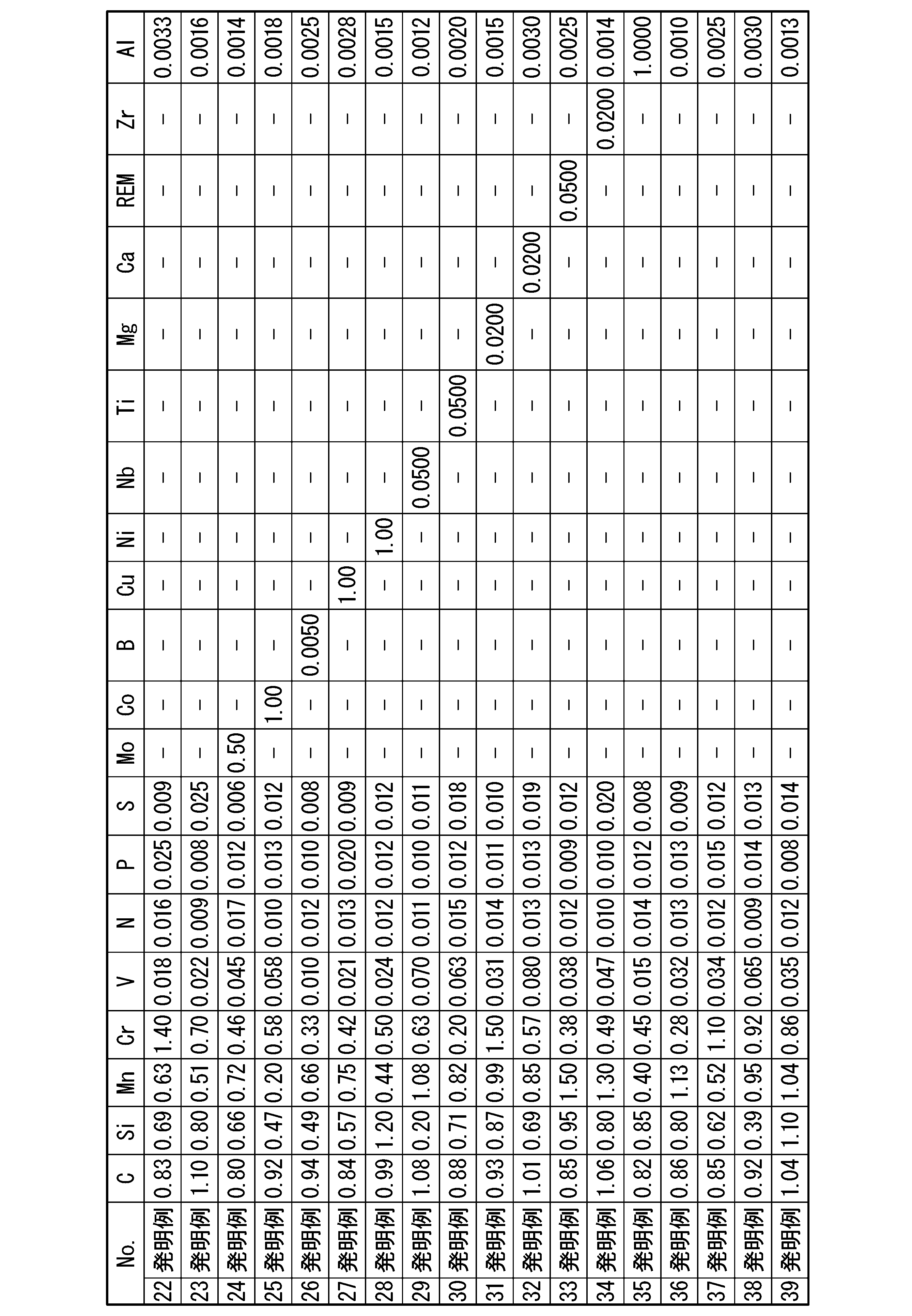
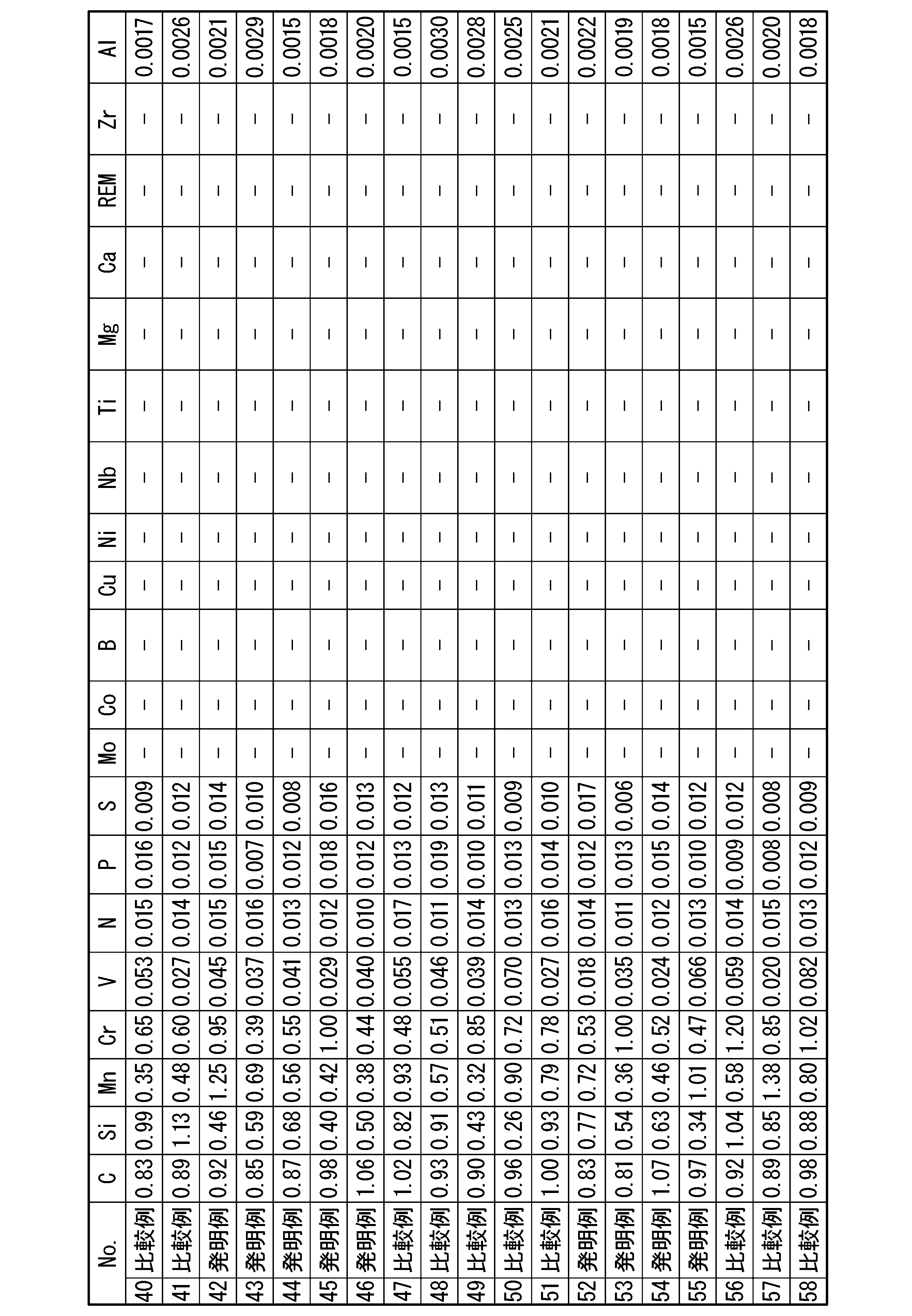
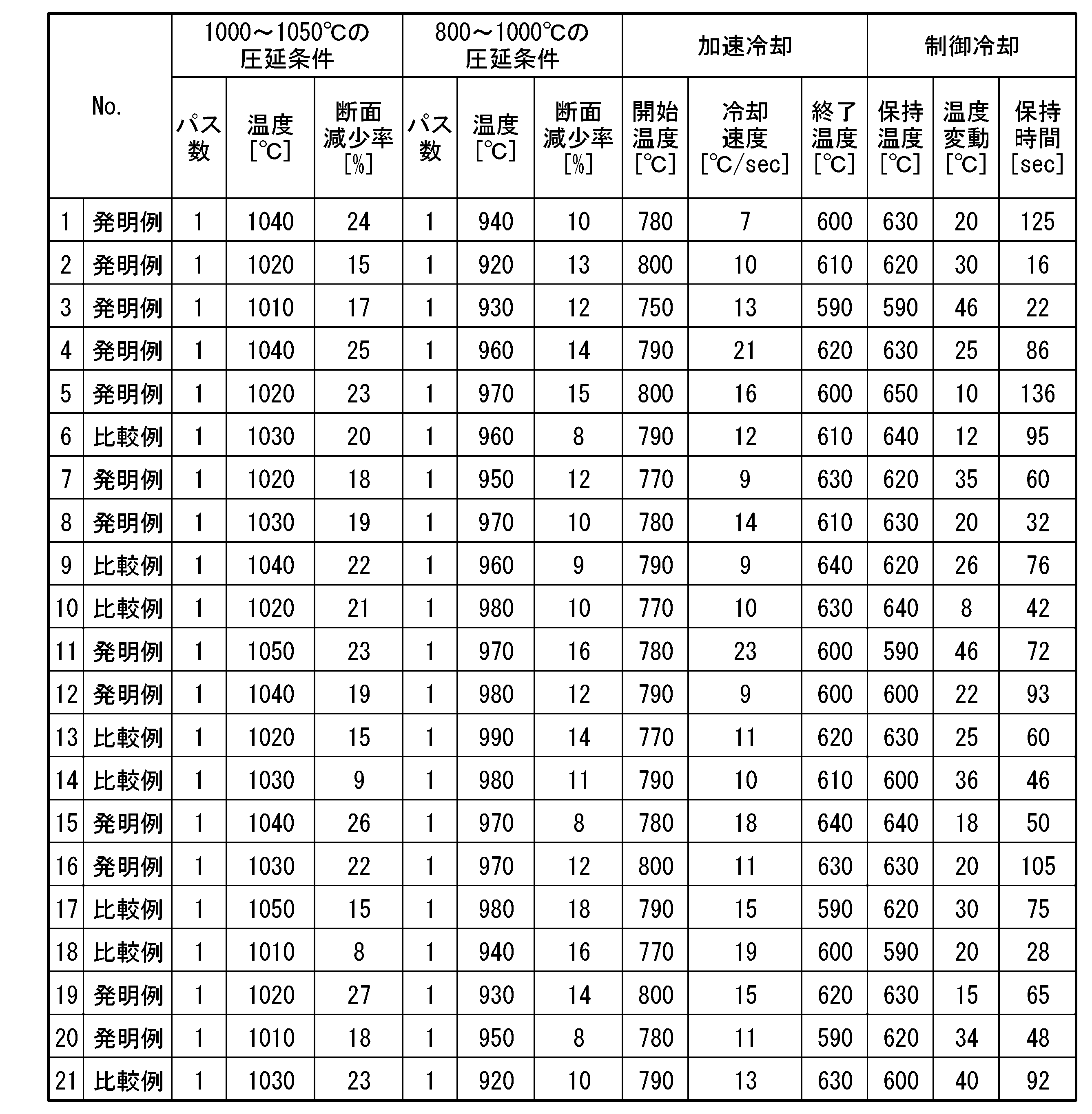
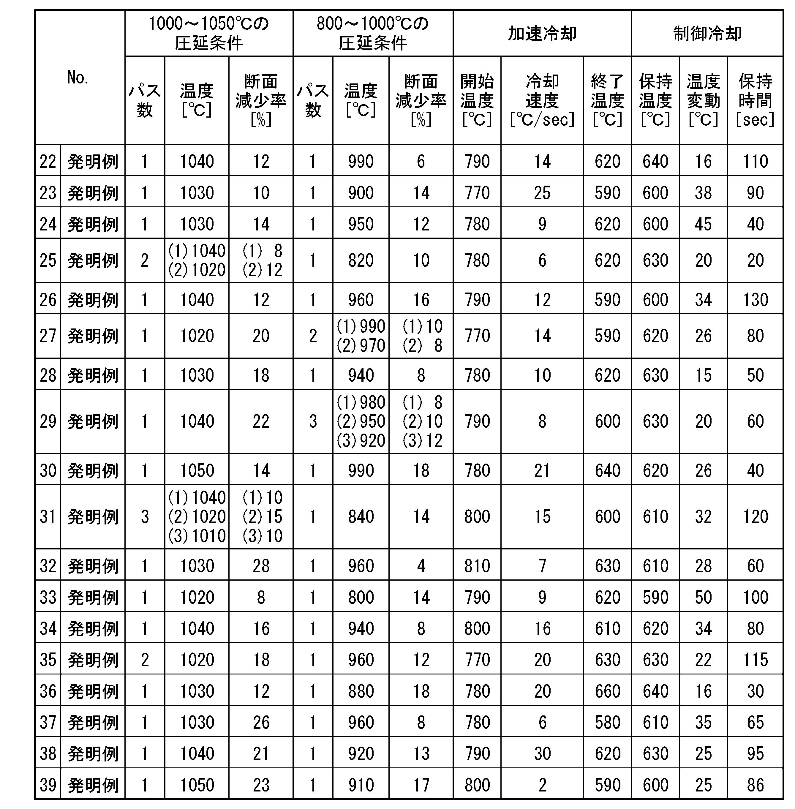


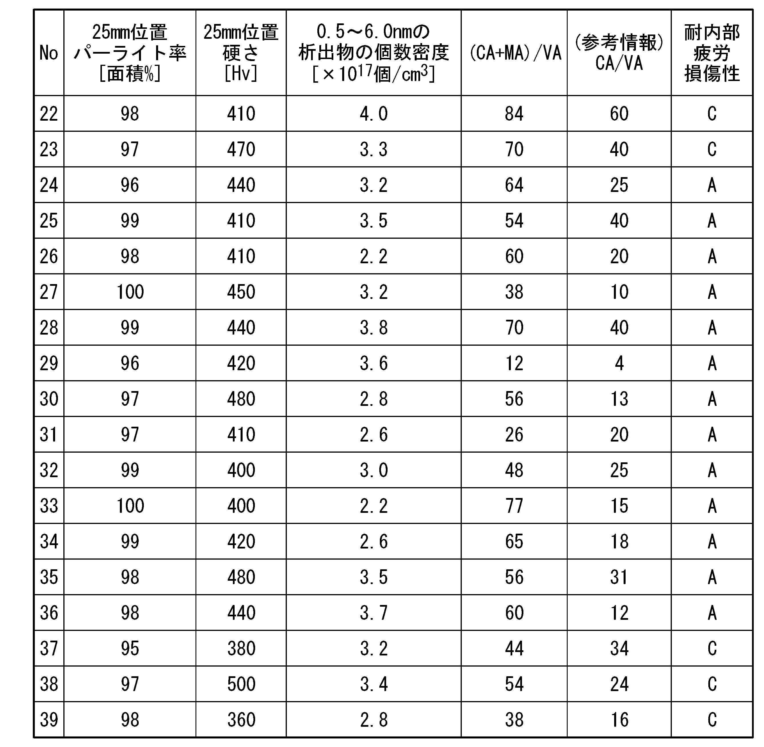
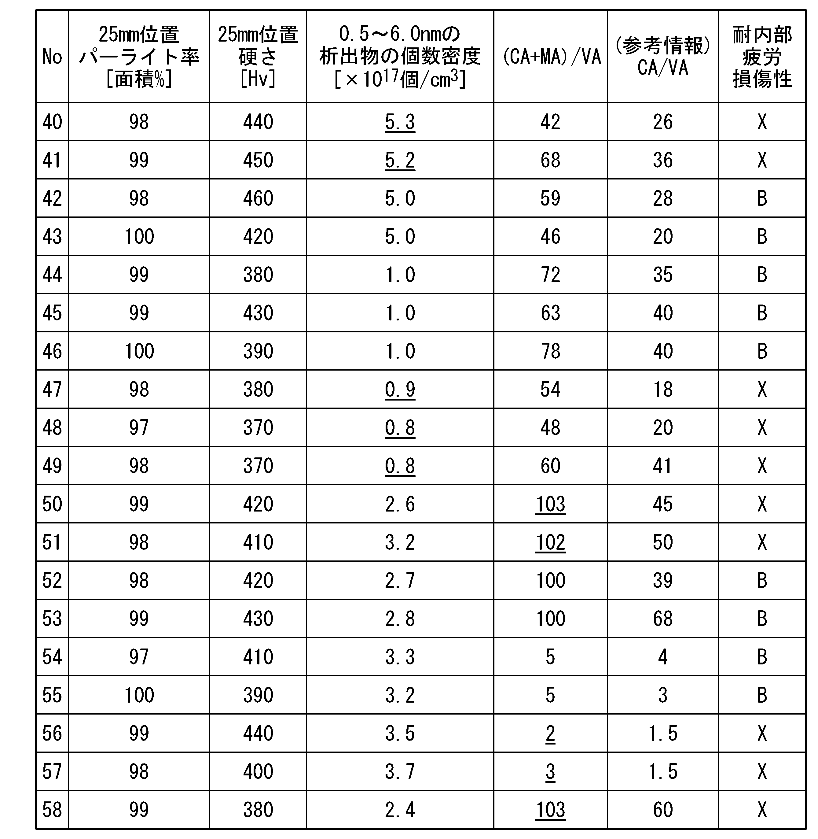
Claims (2)
- 単位質量%で、
C:0.75~1.20%、
Si:0.10~2.00%、
Mn:0.05~2.00%、
Cr:0.05~2.00%、
V:0.005~0.100%、
Al:0.0010~1.0000%、
N:0.006~0.020%、
P≦0.025%、
S≦0.025%、
Mo:0~0.50%、
Co:0~1.00%、
B:0~0.0050%、
Cu:0~1.00%、
Ni:0~1.00%、
Nb:0~0.0500%、
Ti:0~0.0500%、
Mg:0~0.0200%、
Ca:0~0.0200%、
REM:0~0.0500%、及び
Zr:0~0.0200%
を含有し、残部がFe及び不純物からなり、
頭部外郭表面を起点として深さ25mmの位置の金属組織が、面積率で95%以上のパーライト組織を含み、
前記頭部外郭表面を起点として深さ25mmの前記位置で測定されるレールの硬さが、Hv360~500の範囲であり、
前記頭部外郭表面を起点として深さ25mmの前記位置の、前記パーライト組織中のフェライト相において、粒径が0.5~6.0nmの、Cr、Mn及びVを含む窒化物の個数密度が、1cm3あたり1.0×10¹⁷~5.0×10¹⁷個の範囲であり、
前記頭部外郭表面を起点として深さ25mmの前記位置の、前記パーライト組織中の前記フェライト相に含まれる、粒径が0.5~6.0nmの、Cr、Mn及びVを含む前記窒化物において、Vの原子数(VA)に対するCrの原子数(CA)及びMnの原子数(MA)の和の比の平均値を小数点第一位で四捨五入した値((CA+MA)/VA)が下記式1を満足する
ことを特徴とするレール。
5≦(CA+MA)/VA≦100 … 式1 - 単位質量%で、
Mo:0.01~0.50%、
Co:0.01~1.00%、
B:0.0001~0.0050%、
Cu:0.01~1.00%、
Ni:0.01~1.00%、
Nb:0.0010~0.0500%、
Ti:0.0030~0.0500%、
Mg:0.0005~0.0200%、
Ca:0.0005~0.0200%、
REM:0.0005~0.0500%、及び
Zr:0.0001~0.0200%
の一種以上を含有する
ことを特徴とする請求項1に記載のレール。
Priority Applications (3)
| Application Number | Priority Date | Filing Date | Title |
|---|---|---|---|
| AU2022491134A AU2022491134B2 (en) | 2022-12-23 | Rail | |
| JP2024565541A JPWO2024134875A1 (ja) | 2022-12-23 | 2022-12-23 | |
| PCT/JP2022/047622 WO2024134875A1 (ja) | 2022-12-23 | 2022-12-23 | レール |
Applications Claiming Priority (1)
| Application Number | Priority Date | Filing Date | Title |
|---|---|---|---|
| PCT/JP2022/047622 WO2024134875A1 (ja) | 2022-12-23 | 2022-12-23 | レール |
Publications (1)
| Publication Number | Publication Date |
|---|---|
| WO2024134875A1 true WO2024134875A1 (ja) | 2024-06-27 |
Family
ID=91587909
Family Applications (1)
| Application Number | Title | Priority Date | Filing Date |
|---|---|---|---|
| PCT/JP2022/047622 Ceased WO2024134875A1 (ja) | 2022-12-23 | 2022-12-23 | レール |
Country Status (2)
| Country | Link |
|---|---|
| JP (1) | JPWO2024134875A1 (ja) |
| WO (1) | WO2024134875A1 (ja) |
Citations (5)
| Publication number | Priority date | Publication date | Assignee | Title |
|---|---|---|---|---|
| JP2005171326A (ja) * | 2003-12-11 | 2005-06-30 | Nippon Steel Corp | 耐表面損傷性および耐内部疲労損傷性に優れた高炭素鋼レール |
| JP2009108396A (ja) * | 2007-10-10 | 2009-05-21 | Jfe Steel Corp | 耐摩耗性,耐疲労損傷性および耐遅れ破壊性に優れた内部高硬度型パーライト鋼レールおよびその製造方法 |
| JP2010180443A (ja) * | 2009-02-04 | 2010-08-19 | Nippon Steel Corp | 高炭素パーライト系レールの熱処理方法 |
| WO2016117689A1 (ja) * | 2015-01-23 | 2016-07-28 | 新日鐵住金株式会社 | レール |
| WO2020054339A1 (ja) * | 2018-09-10 | 2020-03-19 | 日本製鉄株式会社 | レール、及びレールの製造方法 |
-
2022
- 2022-12-23 WO PCT/JP2022/047622 patent/WO2024134875A1/ja not_active Ceased
- 2022-12-23 JP JP2024565541A patent/JPWO2024134875A1/ja active Pending
Patent Citations (5)
| Publication number | Priority date | Publication date | Assignee | Title |
|---|---|---|---|---|
| JP2005171326A (ja) * | 2003-12-11 | 2005-06-30 | Nippon Steel Corp | 耐表面損傷性および耐内部疲労損傷性に優れた高炭素鋼レール |
| JP2009108396A (ja) * | 2007-10-10 | 2009-05-21 | Jfe Steel Corp | 耐摩耗性,耐疲労損傷性および耐遅れ破壊性に優れた内部高硬度型パーライト鋼レールおよびその製造方法 |
| JP2010180443A (ja) * | 2009-02-04 | 2010-08-19 | Nippon Steel Corp | 高炭素パーライト系レールの熱処理方法 |
| WO2016117689A1 (ja) * | 2015-01-23 | 2016-07-28 | 新日鐵住金株式会社 | レール |
| WO2020054339A1 (ja) * | 2018-09-10 | 2020-03-19 | 日本製鉄株式会社 | レール、及びレールの製造方法 |
Also Published As
| Publication number | Publication date |
|---|---|
| JPWO2024134875A1 (ja) | 2024-06-27 |
| AU2022491134A1 (en) | 2025-04-24 |
Similar Documents
| Publication | Publication Date | Title |
|---|---|---|
| JP7088293B2 (ja) | レール、及びレールの製造方法 | |
| RU2461639C1 (ru) | Рельс с перлитной структурой, обладающий превосходным сопротивлением абразивному износу и отличной ударной вязкостью | |
| US10047411B2 (en) | Rail | |
| EP3249069B1 (en) | Rail | |
| WO2011155481A1 (ja) | 鋼レールおよびその製造方法 | |
| JPWO2010095354A1 (ja) | 耐摩耗性および靭性に優れたパーライト系レール | |
| JP2014101583A (ja) | レールの製造方法 | |
| WO2015182759A1 (ja) | レールおよびその製造方法 | |
| JP5267306B2 (ja) | 高炭素鋼レールの製造方法 | |
| JP7136324B2 (ja) | レール | |
| WO2015182743A1 (ja) | レールおよびその製造方法 | |
| WO2017200096A1 (ja) | レール | |
| JP2004204306A (ja) | 耐摩耗性および靭性に優れた高炭素パーライト系レール | |
| WO2024134875A1 (ja) | レール | |
| AU2022491134B2 (en) | Rail | |
| JP2007254767A (ja) | 高張力厚鋼板の溶接継手 | |
| JP5533307B2 (ja) | パーライト系レールの圧延方法 | |
| JP2006057127A (ja) | 耐落重破壊特性に優れたパーライト系レール | |
| JP2005163087A (ja) | 耐摩耗性および延性に優れた高炭素鋼レールの製造方法 | |
| JP6601167B2 (ja) | 耐摩耗性に優れたレール | |
| JP2017206743A (ja) | 耐摩耗性および靭性に優れたレール |
Legal Events
| Date | Code | Title | Description |
|---|---|---|---|
| 121 | Ep: the epo has been informed by wipo that ep was designated in this application |
Ref document number: 22969258 Country of ref document: EP Kind code of ref document: A1 |
|
| WWE | Wipo information: entry into national phase |
Ref document number: 2024565541 Country of ref document: JP |
|
| WWE | Wipo information: entry into national phase |
Ref document number: AU2022491134 Country of ref document: AU |
|
| ENP | Entry into the national phase |
Ref document number: 2022491134 Country of ref document: AU Date of ref document: 20221223 Kind code of ref document: A |
|
| REG | Reference to national code |
Ref country code: BR Ref legal event code: B01A Ref document number: 112025007026 Country of ref document: BR |
|
| NENP | Non-entry into the national phase |
Ref country code: DE |
|
| ENP | Entry into the national phase |
Ref document number: 112025007026 Country of ref document: BR Kind code of ref document: A2 Effective date: 20250409 |
|
| 122 | Ep: pct application non-entry in european phase |
Ref document number: 22969258 Country of ref document: EP Kind code of ref document: A1 |