WO2024127992A1 - 超音波診断装置および超音波診断装置の制御方法 - Google Patents
超音波診断装置および超音波診断装置の制御方法 Download PDFInfo
- Publication number
- WO2024127992A1 WO2024127992A1 PCT/JP2023/042710 JP2023042710W WO2024127992A1 WO 2024127992 A1 WO2024127992 A1 WO 2024127992A1 JP 2023042710 W JP2023042710 W JP 2023042710W WO 2024127992 A1 WO2024127992 A1 WO 2024127992A1
- Authority
- WO
- WIPO (PCT)
- Prior art keywords
- category
- breast
- region
- mammary gland
- ultrasound
- Prior art date
- Legal status (The legal status is an assumption and is not a legal conclusion. Google has not performed a legal analysis and makes no representation as to the accuracy of the status listed.)
- Ceased
Links
Images






Classifications
-
- A—HUMAN NECESSITIES
- A61—MEDICAL OR VETERINARY SCIENCE; HYGIENE
- A61B—DIAGNOSIS; SURGERY; IDENTIFICATION
- A61B8/00—Diagnosis using ultrasonic, sonic or infrasonic waves
- A61B8/08—Clinical applications
- A61B8/0825—Clinical applications for diagnosis of the breast, e.g. mammography
-
- A—HUMAN NECESSITIES
- A61—MEDICAL OR VETERINARY SCIENCE; HYGIENE
- A61B—DIAGNOSIS; SURGERY; IDENTIFICATION
- A61B8/00—Diagnosis using ultrasonic, sonic or infrasonic waves
- A61B8/44—Constructional features of the ultrasonic, sonic or infrasonic diagnostic device
- A61B8/4427—Device being portable or laptop-like
-
- A—HUMAN NECESSITIES
- A61—MEDICAL OR VETERINARY SCIENCE; HYGIENE
- A61B—DIAGNOSIS; SURGERY; IDENTIFICATION
- A61B8/00—Diagnosis using ultrasonic, sonic or infrasonic waves
- A61B8/44—Constructional features of the ultrasonic, sonic or infrasonic diagnostic device
- A61B8/4444—Constructional features of the ultrasonic, sonic or infrasonic diagnostic device related to the probe
- A61B8/4472—Wireless probes
-
- A—HUMAN NECESSITIES
- A61—MEDICAL OR VETERINARY SCIENCE; HYGIENE
- A61B—DIAGNOSIS; SURGERY; IDENTIFICATION
- A61B8/00—Diagnosis using ultrasonic, sonic or infrasonic waves
- A61B8/46—Ultrasonic, sonic or infrasonic diagnostic devices with special arrangements for interfacing with the operator or the patient
- A61B8/461—Displaying means of special interest
- A61B8/463—Displaying means of special interest characterised by displaying multiple images or images and diagnostic data on one display
-
- A—HUMAN NECESSITIES
- A61—MEDICAL OR VETERINARY SCIENCE; HYGIENE
- A61B—DIAGNOSIS; SURGERY; IDENTIFICATION
- A61B8/00—Diagnosis using ultrasonic, sonic or infrasonic waves
- A61B8/52—Devices using data or image processing specially adapted for diagnosis using ultrasonic, sonic or infrasonic waves
- A61B8/5215—Devices using data or image processing specially adapted for diagnosis using ultrasonic, sonic or infrasonic waves involving processing of medical diagnostic data
- A61B8/5223—Devices using data or image processing specially adapted for diagnosis using ultrasonic, sonic or infrasonic waves involving processing of medical diagnostic data for extracting a diagnostic or physiological parameter from medical diagnostic data
-
- A—HUMAN NECESSITIES
- A61—MEDICAL OR VETERINARY SCIENCE; HYGIENE
- A61B—DIAGNOSIS; SURGERY; IDENTIFICATION
- A61B8/00—Diagnosis using ultrasonic, sonic or infrasonic waves
- A61B8/08—Clinical applications
- A61B8/0833—Clinical applications involving detecting or locating foreign bodies or organic structures
- A61B8/085—Clinical applications involving detecting or locating foreign bodies or organic structures for locating body or organic structures, e.g. tumours, calculi, blood vessels, nodules
-
- A—HUMAN NECESSITIES
- A61—MEDICAL OR VETERINARY SCIENCE; HYGIENE
- A61B—DIAGNOSIS; SURGERY; IDENTIFICATION
- A61B8/00—Diagnosis using ultrasonic, sonic or infrasonic waves
- A61B8/08—Clinical applications
- A61B8/0858—Clinical applications involving measuring tissue layers, e.g. skin, interfaces
-
- A—HUMAN NECESSITIES
- A61—MEDICAL OR VETERINARY SCIENCE; HYGIENE
- A61B—DIAGNOSIS; SURGERY; IDENTIFICATION
- A61B8/00—Diagnosis using ultrasonic, sonic or infrasonic waves
- A61B8/48—Diagnostic techniques
- A61B8/483—Diagnostic techniques involving the acquisition of a 3D volume of data
Definitions
- the present invention relates to an ultrasound diagnostic device used to examine the breasts of a subject, and a method for controlling the ultrasound diagnostic device.
- an ultrasound diagnostic device is equipped with an ultrasound probe that contains an array of transducers and a device main body that is connected to the ultrasound probe.
- An ultrasound beam is transmitted from the ultrasound probe to the subject, and the ultrasound echo from the subject is received by the ultrasound probe.
- An ultrasound image is generated by electrically processing the received signal.
- the composition of breast fat and glandular tissue varies from person to person, but the anatomical structure of the breast is the same: in the glandular tissue, the main duct branches into extralobular ducts, which then connect to numerous lobules.
- the stroma is present around the lobules, and the stroma and other components of the glandular tissue make up the glandular tissue. It is known that there are two types of stroma around the lobules: surrounding stroma and edematous stroma.
- the surrounding stroma is present along the structure from the lobule to the milk duct, and contains a lot of collagen fibers.
- the edematous stroma fills the gaps between the surrounding stroma, and is rich in matrix, with collagen fibers and fat mixed in, and less collagen fibers than the surrounding stroma.
- Non-Patent Document 1 reports that even if the glandular area is almost the same, cancer is more likely to occur when the proportion of GTC (Glandular Tissue Component) areas, which include the milk ducts, lobules, and surrounding stroma, in the glandular area is high.
- GTC Global Tissue Component
- the proportion of the GTC area in the glandular area can be a risk factor. This means that the risk is high in patients whose lobules do not degenerate.
- Patent Document 1 discloses an ultrasonic diagnostic device that extracts a mammary gland region by detecting a boundary in the depth direction of an ultrasonic image, and detects a lesion existing in the mammary gland region.
- the ultrasound diagnostic device in Patent Document 1 aims to detect lesions within the mammary gland region, and is not interested in dividing the mammary gland region into smaller tissues. This poses the problem that it is not possible to consider in detail the risk of cancer in the mammary gland region.
- the present invention has been made to solve these problems, and aims to provide an ultrasound diagnostic device that allows the user to closely examine the risk of cancer in the breast area of a subject.
- a first category determination unit that determines a category of a glandular tissue composition in a breast based on an ultrasound image including a mammary gland region in a subject's breast; and a category output unit that outputs the category of the glandular tissue composition determined by the first category determination unit.
- the first category determination unit determines the category of glandular tissue composition using a trained model machine-learned based on multiple teacher data items each including an ultrasound image of a breast and a category of glandular tissue composition in the breast.
- the first category determination unit a mammary gland region extraction unit that extracts a mammary gland region from an ultrasound image including the mammary gland region in the breast of a subject; and a second category determination unit that determines a category of glandular tissue composition in the breast based on the mammary gland area extracted by the mammary gland area extraction unit.
- the second category determination unit determines the category of glandular tissue composition using a trained model machine-learned based on multiple teacher data each including an ultrasound image including a mammary gland region in the breast, a mammary gland region extracted by the mammary gland region extraction unit, and a category of glandular tissue composition in the breast.
- the first category determination unit a mammary gland region extraction unit that extracts a mammary gland region from an ultrasound image including the mammary gland region in the breast of a subject; a glandular tissue composition region extraction unit that extracts a glandular tissue composition region including ducts, lobules, and surrounding stroma from the glandular region extracted by the glandular region extraction unit; and a third category determination unit that determines a category of glandular tissue composition in the breast based on the glandular tissue composition region extracted by the glandular tissue composition region extraction unit.
- the ultrasound diagnostic device according to any one of [7] to [9], wherein the glandular tissue composition region extraction unit extracts a glandular tissue composition region by performing image analysis on an ultrasound image in which a mammary gland region is captured.
- the glandular tissue composition region extraction unit extracts the mammary gland region by performing image analysis on the ultrasound image.
- the mammary gland region extraction unit extracts the mammary gland region using a trained model that has been machine-learned based on multiple pieces of teacher data, each of which includes an ultrasound image of the breast and a mammary gland region in the breast.
- the ultrasound diagnostic device according to any one of [1] to [12], wherein the first category determination unit determines a category of glandular tissue composition based on a plurality of ultrasound images taken at a plurality of specified locations of the subject's breast.
- the ultrasound image is a three-dimensional ultrasound image;
- the ultrasound diagnostic device according to any one of claims 1 to 13, wherein the first category determination unit determines a category of glandular tissue composition based on a three-dimensional ultrasound image.
- the ultrasound diagnostic device is equipped with a first category determination unit that determines the category of glandular tissue composition in the breast based on an ultrasound image including the mammary gland region in the subject's breast, and a category output unit that outputs the category of glandular tissue composition determined by the first category determination unit, thereby enabling a more detailed consideration of cancer risk than the conventional consideration based only on observation of the mammary gland region.
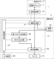
- FIG. 1 is a block diagram showing a configuration of an ultrasound diagnostic apparatus according to a first embodiment of the present invention
- 2 is a block diagram showing an internal configuration of a transmission/reception circuit according to the first embodiment
- 4 is a block diagram showing an internal configuration of an image generating unit in the first embodiment.
- FIG. 1 is a diagram showing an ultrasound image of a mammary gland region of a subject.
- FIG. 13 is a diagram showing an example of display of categories of glandular tissue composition.
- 4 is a flowchart showing the operation of the first embodiment.
- 10 is a flowchart illustrating a modified example of the operation of the first embodiment.
- FIG. 11 is a block diagram showing an internal configuration of a first category determination unit in the second embodiment.
- FIG. 1 is a block diagram showing a configuration of an ultrasound diagnostic apparatus according to a first embodiment of the present invention
- 2 is a block diagram showing an internal configuration of a transmission/reception circuit according to the first embodiment
- 4 is a block diagram showing an internal
- FIG. 13 is a block diagram showing an internal configuration of a first category determination unit in the third embodiment.
- FIG. 2 is a diagram showing an ultrasound image of a mammary gland region in which a GTC region is photographed.
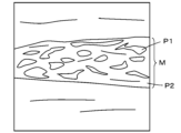
- FIG. 13 is a diagram showing a binarized image in which a mammary gland region has been binarized using a brightness threshold value.
- FIG. 13 is a block diagram showing the configuration of an ultrasound diagnostic apparatus according to embodiment 4.
- FIG. 13 is a diagram showing the configuration of a schematic diagram of a breast generated in embodiment 4.
- FIG. 1 shows a schematic diagram of a breast with a probe mark. 13 is a flowchart showing the operation of the fourth embodiment.
- the ultrasonic diagnostic apparatus includes an ultrasonic probe 1 and an apparatus main body 2.
- the ultrasonic probe 1 and the apparatus main body 2 are wired to each other via a cable (not shown).
- the ultrasound probe 1 has a transducer array 11 and a transmission/reception circuit 12 connected to the transducer array 11.
- the device main body 2 has an image generation unit 21 connected to the transmission/reception circuit 12 of the ultrasound probe 1, and a display control unit 22 and a monitor 23 are sequentially connected to the image generation unit 21, and an image memory 24 is connected to the image generation unit 21.
- a first category determination unit 25 and a category output unit 26 are sequentially connected to the image memory 24.
- the category output unit 26 is connected to the display control unit 22.
- the main body control unit 27 is connected to the transmission/reception circuit 12, the image generation unit 21, the display control unit 22, the image memory 24, the first category determination unit 25, and the category output unit 26.
- An input device 28 is connected to the main body control unit 27.
- the image generation unit 21, the display control unit 22, the first category determination unit 25, the category output unit 26, and the main body control unit 27 constitute a processor 31 for the device main body 2.
- the transducer array 11 of the ultrasound probe 1 has multiple ultrasound transducers arranged one-dimensionally or two-dimensionally. Each of these transducers transmits ultrasound waves according to a drive signal supplied from the transmission/reception circuit 12, and receives reflected waves from the subject to output an analog reception signal.
- Each transducer is constructed by forming electrodes on both ends of a piezoelectric body made of, for example, a piezoelectric ceramic such as PZT (Lead Zirconate Titanate), a polymer piezoelectric element such as PVDF (Poly Vinylidene Di Fluoride), or a piezoelectric single crystal such as PMN-PT (Lead Magnesium Niobate-Lead Titanate).
- the transmission/reception circuit 12 transmits ultrasonic waves from the transducer array 11 and generates sound ray signals based on the reception signals acquired by the transducer array 11.
- the transmission/reception circuit 12 has a pulser 13 connected to the transducer array 11, an amplifier unit 14, an AD (Analog Digital) conversion unit 15, and a beamformer 16 connected in series to the transducer array 11.
- the pulser 13 includes, for example, multiple pulse generators, and adjusts the delay of each drive signal to the multiple transducers of the transducer array 11 based on a transmission delay pattern selected in response to a control signal from the main body control unit 27, so that the ultrasound transmitted from the multiple transducers forms an ultrasonic beam.
- a pulsed or continuous wave voltage is applied to the electrodes of the transducers of the transducer array 11, the piezoelectric body expands and contracts, and pulsed or continuous wave ultrasound is generated from each transducer, and an ultrasonic beam is formed from the composite wave of these ultrasound waves.
- the transmitted ultrasonic beam is reflected by an object, such as a part of the subject, and an ultrasonic echo propagates toward the transducer array 11 of the ultrasonic probe 1.
- the ultrasonic echo propagating toward the transducer array 11 in this manner is received by each of the transducers that make up the transducer array 11.
- each of the transducers that make up the transducer array 11 expands and contracts upon receiving the propagating ultrasonic echo, generating a received signal that is an electrical signal, and outputs these received signals to the amplifier unit 14.
- the amplifier 14 amplifies the signals input from each transducer that constitutes the transducer array 11 and transmits the amplified signals to the AD converter 15.
- the AD converter 15 converts the signals transmitted from the amplifier 14 into digital reception data and transmits these reception data to the beamformer 16.
- the beamformer 16 performs so-called reception focusing processing by adding each reception data converted by the AD converter 15 with a respective delay according to the sound speed or sound speed distribution set based on the reception delay pattern selected in response to a control signal from the main body control unit 27. This reception focusing processing causes the reception data converted by the AD converter 15 to be phased and added, and a sound ray signal with a narrowed focus of the ultrasonic echo is obtained.
- the image generating section 21 of the apparatus main body 2 has a configuration in which a signal processing section 41, a DSC (Digital Scan Converter) 42, and an image processing section 43 are connected in series.
- the signal processing unit 41 performs correction for attenuation due to distance on the sound ray signals sent from the transmission/reception circuit 12 of the ultrasonic probe 1 in accordance with the depth of the reflection position of the ultrasonic waves, and then performs envelope detection processing to generate an ultrasonic image signal (B-mode image signal) which is tomographic image information on the tissue in the subject.
- B-mode image signal ultrasonic image signal
- the DSC 42 converts (raster converts) the ultrasonic image signal generated by the signal processor 41 into an image signal conforming to a scanning method for a normal television signal.
- the image processing unit 43 performs various necessary image processing such as gradation processing on the ultrasound image signal input from the DSC 42, and then outputs a signal representing the ultrasound image to the display control unit 22 and the image memory 24.
- the signal representing the ultrasound image generated by the image generation unit 21 in this manner will be simply called an ultrasound image.
- the image generation unit 21 can also output the ultrasound image signal before processing by the DSC 42 or the ultrasound image signal immediately after processing by the DSC 42 to the image memory 24. In this case, the image generation unit 21 can generate an ultrasound image by reading these signals from the image memory 24 and processing them by the DSC 42 or the image processing unit 43.
- the display control unit 22 Under the control of the main body control unit 27 , the display control unit 22 performs predetermined processing on the ultrasound image sent from the image generating unit 21 , and displays the ultrasound image on the monitor 23 .
- the monitor 23 displays an ultrasound image under the control of the display control unit 22, and includes a display device such as an LCD (Liquid Crystal Display) or an organic EL display (Organic Electroluminescence Display).
- the image memory 24 is a memory that stores ultrasound images generated by the image generation unit 21 under the control of the main body control unit 27.
- the image memory 24 can hold multiple frames of ultrasound images generated by the image generation unit 21 in response to a diagnosis of the mammary gland region of the subject's breast.
- the image memory 24 can be a flash memory, HDD (Hard Disc Drive), SSD (Solid State Drive), FD (Flexible Disc), MO disk (Magneto-Optical disc), MT (Magnetic Tape), RAM (Random Access Memory), CD (Compact Disc), DVD (Digital Versatile Disc), SD card (Secure Digital card), USB memory (Universal Serial Bus memory), or other recording media.
- HDD Hard Disc Drive
- SSD Solid State Drive
- FD Fexible Disc
- MO disk Magnetic-Optical disc
- MT Magnetic Tape
- RAM Random Access Memory
- CD Compact Disc
- DVD Digital Versatile Disc
- SD card Secure Digital card
- USB memory Universal Serial Bus memory
- the first category determination unit 25 determines the category of the glandular tissue component (GTC) in the subject's breast based on an ultrasound image including a mammary gland region in the breast.
- GTC glandular tissue component
- the follicular region includes the GTC region, which includes the ducts, lobules, and surrounding stroma. In the follicular region, the spaces between the surrounding stroma are filled with edematous stroma. It is generally known that lobules shrink with age, but as disclosed in, for example, "Su Hyun Lee et al. "Glandular Tissue Component and Breast Cancer Risk in Mammographically Dense Breasts at Screening Breast US", Radiology, Volume 301, October 1, 2021", there are research results showing that patients in whom lobule shrinkage does not progress are at high risk of breast cancer.
- the GTC category represents the degree of progression of lobule shrinkage and can be used as a criterion for determining breast cancer risk.
- FIG 4 shows an example of an ultrasound image of a subject's breast.
- This ultrasound image is a cross-sectional image taken by contacting the tip of ultrasound probe 1 with the subject's breast, with the subject's skin S appearing at the top of the ultrasound image, which shows the shallowest part, and the pectoralis major muscle T appearing at the bottom of the ultrasound image, which shows the deeper part.
- the breast region BR is located in the area between the skin S and the pectoralis major muscle T.
- the first category determination unit 25 can determine the GTC category using a trained model that is machine-learned based on multiple training data including ultrasound images of the breast and GTC categories in the breast, as shown in FIG. 4.
- the correspondence between the ultrasound images in the training data and the GTC categories can be performed by an expert such as a skilled doctor.
- the first category determination unit 25 can output one of a number of predetermined categories as the GTC category, for example, one of four categories: Minimal, Mild, Moderate, and Marked. Mild indicates that the lobule degenerates less than Minimal, Moderate indicates that the lobule degenerates less than Mild, and Marked indicates that the lobule degenerates less than Moderate.
- the first category determination unit 25 can also determine, for example, one of two categories: Low and High, as the GTC category.
- the category output unit 26 outputs the GTC category determined by the first category determination unit 25, and sends the output category to the display control unit 22.
- the display control unit 22 can display the GTC category on the monitor 23, for example, by a message E as shown in FIG. 5. In the example of FIG. 5, a message E indicating "Marked" is displayed. By checking the message E, a user such as a doctor can easily grasp the GTC category of the subject, consider in detail the risk of cancer in the mammary gland region, and easily manage the risk of breast cancer for the subject.
- the main body control unit 27 controls each part of the device main body 2 and the transmission/reception circuit 12 of the ultrasonic probe 1 based on a control program stored in advance.
- a main body side storage unit is connected to the main body control unit 27.
- the main body side storage unit stores control programs and the like.
- a flash memory, a RAM, an SD card, an SSD, or the like can be used as the main body side storage unit.
- the input device 28 allows the user to perform input operations, and is composed of devices such as a keyboard, a mouse, a trackball, a touchpad, or a touch sensor placed over the monitor 23.
- the processor 31 having the image generation unit 21, display control unit 22, first category determination unit 25, category output unit 26 and main body control unit 27 is composed of a CPU (Central Processing Unit) and a control program for causing the CPU to perform various processes, but may also be composed of an FPGA (Field Programmable Gate Array), a DSP (Digital Signal Processor), an ASIC (Application Specific Integrated Circuit), a GPU (Graphics Processing Unit) or other ICs (Integrated Circuits), or a combination of these.
- a CPU Central Processing Unit
- FPGA Field Programmable Gate Array
- DSP Digital Signal Processor
- ASIC Application Specific Integrated Circuit
- GPU Graphics Processing Unit
- other ICs Integrated Circuits
- the image generating unit 21, the display control unit 22, the first category determining unit 25, the category output unit 26, and the main body control unit 27 of the processor 31 can be configured as being partially or entirely integrated into a single CPU or the like.
- step S1 the subject's breast is photographed and an ultrasound image is acquired using the ultrasound probe 1.
- transmission and reception of ultrasound is started from the multiple transducers of the transducer array 11 in accordance with a drive signal from the pulsar 13 of the transmission and reception circuit 12 of the ultrasound probe 1
- ultrasound echoes from within the subject's breast are received by the multiple transducers of the transducer array 11, and the received signals, which are analog signals, are output to the amplifier unit 14 and amplified, and are AD converted by the AD conversion unit 15 to acquire the received data.
- the beamformer 16 performs reception focusing on this received data, and the sound ray signals thus generated are sent to the image generation unit 21 of the device body 2, which generates an ultrasound image showing tomographic image information of the subject's breast.
- the signal processing unit 41 of the image generation unit 21 performs attenuation correction and envelope detection processing on the sound ray signals according to the depth of the ultrasonic reflection position, and the DSC 42 converts them into an image signal that follows the scanning method of a normal television signal, and the image processing unit 43 performs various necessary image processing such as gradation processing.
- step S2 the ultrasound image generated by the image generating unit 21 is displayed on the monitor 23 via the display control unit 22, and is also stored in the image memory 24.
- the transmission intensity of the ultrasound and the depth range of the ultrasound image displayed on the monitor 23 are adjusted under the control of the main body control unit 27 so that the entire subject's breast, i.e., for example, the depth portion between the subject's skin S and the pectoral muscle T shown in Figure 4, fits within the screen.
- the main body control unit 27 determines whether or not there is an instruction from the user to determine the GTC category.
- the main body control unit 27 can determine that there is an instruction to determine the GTC category when, for example, an instruction to determine the GTC category is input from the user via the input device 28. Also, the main body control unit 27 can determine that there is no instruction to determine the GTC category when, for example, an instruction to determine the GTC category is not input from the user via the input device 28.
- step S3 If it is determined in step S3 that there is no instruction to determine the GTC category, the process returns to step S1 and a new ultrasound image is acquired. Once a new ultrasound image has been acquired in this manner, the ultrasound image is displayed on the monitor 23 in step S2, and the ultrasound image is stored in the image memory 24. In this manner, the processes of steps S1 to S3 are repeated as long as it is determined in step S3 that there is no instruction to determine the GTC category.
- step S3 The user repeats steps S1 to S3, adjusting the position of the ultrasound probe 1 on the subject's body surface while checking the ultrasound image displayed on the monitor 23. If it is determined in step S3 that there is an instruction to determine the GTC category, the process proceeds to step S4.
- the first category determination unit 25 determines the category of GTC in the subject's breast based on the ultrasound image stored in the image memory 24 in the previous step S2. At this time, the first category determination unit 25 can determine the GTC category using a trained model that has been machine-learned based on multiple teacher data, each of which includes an ultrasound image of the breast and a category of GTC in the breast. The first category determination unit 25 can determine the GTC category to be one of multiple categories, such as one of the four categories of Minimal, Mild, Moderate, and Marked, or one of the two categories of Low and High.
- step S5 the category output unit 26 outputs the GTC category determined in step S4.
- the GTC category output here is sent to the display control unit 22 and displayed on the monitor 23, for example, by a message E shown in Fig. 5. This allows a user such as a doctor to easily grasp the degree of progression of lobule involution in the subject's breast and to easily and intuitively perform risk management for breast cancer for the subject.
- the first category determination unit 25 determines the GTC category in the breast based on an ultrasound image including the mammary gland region of the subject's breast, and the category output unit 26 outputs the GTC category, so that the user can easily grasp the degree of progression of lobule degeneration in the subject's breast, thereby considering in detail the risk of cancer in the mammary gland region and easily managing the subject's risk of breast cancer.
- the transmitting/receiving circuit 12 is described as being provided in the ultrasonic probe 1 , the transmitting/receiving circuit 12 may be provided in the device main body 2 . Further, although the image generating unit 21 is described as being provided in the device main body 2, the image generating unit 21 may be provided in the ultrasound probe 1.
- the device main body 2 may be a so-called stationary type, a portable type that is easy to carry, or a so-called handheld type that is configured, for example, by a smartphone or tablet computer. In this way, the type of device that configures the device main body 2 is not particularly limited.
- the ultrasonic probe 1 and the device body 2 are connected to each other by wire, the ultrasonic probe 1 and the device body 2 may be connected to each other wirelessly.
- the ultrasound image generated by the image generating unit 21 is a two-dimensional ultrasound image, but the image generating unit 21 can also be configured to generate a three-dimensional ultrasound image of the subject's breast. After acquiring a plurality of two-dimensional ultrasound images in a plurality of different cross-sectional planes by scanning the ultrasound probe 1 in a plane, a three-dimensional ultrasound image can be generated based on these two-dimensional ultrasound images, or a three-dimensional probe can be used instead of the ultrasound probe 1, and a three-dimensional ultrasound image can be generated while the three-dimensional probe is kept stationary.
- the GTC category output by the category output unit 26 is displayed on the monitor 23 as message E as shown in FIG. 5, the method of informing the user of the GTC category is not limited to this.
- the GTC category can also be output as sound via the speaker. Even in this case, the user can easily grasp the degree of progression of lobule degeneration in the subject's breast.
- ultrasound images can be represented as data in the so-called DICOM (Digital Imaging and Communications in Medicine) format, and can have tags that store additional information.
- the GTC category can be stored in a tag that accompanies the ultrasound image. This allows users, such as doctors, to check the GTC category when checking ultrasound images after an examination.
- the GTC category can also be stored in the image memory 24, for example, superimposed as text information on the corresponding ultrasound image.
- the device main body 2 may also include a report creation unit (not shown) that creates a report based on the GTC category output from the category output unit 26 and the corresponding ultrasound image.
- the report includes at least the corresponding ultrasound image and GTC category.
- the ultrasound diagnostic device of embodiment 1 can also determine the GTC category based on multiple frames of ultrasound image. This aspect will be described using the flowchart in FIG. 7.
- step S11 the breast of the subject is imaged using the ultrasonic probe 1 in the same manner as in step S1, and an ultrasonic image is obtained.
- step S12 the ultrasound image acquired in step S11 is displayed on the monitor 23 in the same manner as in step S2.
- step S13 the main body control unit 27 determines whether or not to start saving the ultrasound image.
- the main body control unit 27 can determine to start saving the ultrasound image, for example, when an instruction to start saving the ultrasound image is input by the user via the input device 28.
- the main body control unit 27 can determine not to start saving the ultrasound image, for example, when an instruction to start saving the ultrasound image is not input by the user via the input device 28.
- step S13 If it is determined in step S13 that saving of the ultrasound image should not be started, the process returns to step S11, a new ultrasound image is acquired, and in the following step S12, the ultrasound image acquired in step S11 is displayed on the monitor 23. In this way, as long as it is determined in step S13 that saving of the ultrasound image should not be started, the processes of steps S11 to S13 are repeated. If it is determined in step S13 that saving of the ultrasound image should be started, the process proceeds to step S14.
- step S14 a new ultrasound image is acquired in the same manner as in step S11.
- step S15 the ultrasound image acquired in step S14 is stored in the image memory 24.
- the main body control unit 27 determines whether or not to end the storage of the ultrasound image. At this time, the main body control unit 27 can determine to end the storage of the ultrasound image, for example, when an instruction to end the storage of the ultrasound image is input by the user via the input device 28. Also, the main body control unit 27 can determine to continue the storage of the ultrasound image, for example, when an instruction to end the storage of the ultrasound image is not input by the user via the input device 28.
- step S16 If it is determined in step S16 that storage of the ultrasound image should continue, the process returns to step S14 where a new ultrasound image is acquired, and then the ultrasound image is stored in the image memory 24 in step S15. In this manner, the processes of steps S14 to S16 are repeated as long as it is determined in step S16 that storage of the ultrasound image should continue. This causes multiple frames of ultrasound images to be stored in the image memory 24. If it is determined in step S16 that storage of the ultrasound image should end, the process proceeds to step S17.
- step S17 the first category determination unit 25 determines the GTC category for each of the multiple frames of ultrasound images stored in the image memory 24 by repeating steps S14 to S16.
- step S18 the category output unit 26 calculates a final GTC category based on the multiple GTC categories determined in step S17 based on multiple frames of ultrasound images, and outputs the calculated final GTC category.
- the category output unit 26 can, for example, calculate the most common category among a plurality of GTC categories as the final GTC category. For example, if the Marked category is determined to be the most common among the four categories of Minimal, Mild, Moderate, and Marked in step S17, the category output unit 26 can calculate the Marked category as the final GTC category.
- step S18 When the processing of step S18 is completed in this manner, the operation of the ultrasound diagnostic device according to the flowchart in Figure 7 is completed.
- the GTC category is determined for each of those ultrasound images.
- the final GTC category can be determined based on the multiple categories calculated for the multiple frames of ultrasound images.
- the ultrasound diagnostic apparatus of the second embodiment includes a first category determination unit 25A shown in Fig. 8 instead of the first category determination unit 25 in the ultrasound diagnostic apparatus of the first embodiment shown in Fig. 1.
- the first category determination unit 25A has a configuration in which a mammary gland region extraction unit 61 and a second category determination unit 62 are connected in series.
- the mammary gland region extraction unit 61 extracts the mammary gland region from an ultrasound image including the mammary gland region in the subject's breast. As shown in FIG. 4, the mammary gland region extraction unit 61 recognizes an anterior boundary line L1 located on the shallower side and a posterior boundary line L2 located on the deeper side within the breast region BR, and can extract the deep region between the anterior boundary line L1 and the posterior boundary line L2 as the mammary gland region M.
- the mammary gland region extraction unit 61 can extract the mammary gland region, for example, by performing image analysis on the ultrasound image. At this time, the mammary gland region extraction unit 61 can extract the mammary gland region M by searching within the ultrasound image using, for example, so-called template matching, or image analysis techniques that utilize features such as Adaboost (Adaptive Boosting), SVM (Support Vector Machine), or SIFT (Scale-Invariant Feature Transform).
- Adaboost Adaptive Boosting
- SVM Serial Vector Machine
- SIFT Scale-Invariant Feature Transform
- the mammary gland region extraction unit 61 can also extract the mammary gland region M using a trained model that is machine-learned based on multiple training data each including, for example, an ultrasound image of a breast and the mammary gland region M in that breast.
- the second category determination unit 62 determines the category of GTC in the breast based on the mammary gland region M extracted by the mammary gland region extraction unit 61.
- the second category determination unit 62 can determine the category of GTC using a trained model that has been machine-learned based on a plurality of teacher data, each of which includes an ultrasound image including the mammary gland region M in the breast, the mammary gland region M extracted by the mammary gland region extraction unit 61, and the category of GTC in the breast.
- the mammary gland region M used for machine learning is represented, for example, in the form of so-called polygon coordinate information.
- the GTC category thus determined by the first category determination unit 25A is output by the category output unit 26.
- the GTC category output by the category output unit 26 is displayed on the monitor 23 by message E, for example, as shown in FIG. 5.
- the GTC category in the subject's breast is determined by the first category determination unit 25A and the GTC category is output by the category output unit 26 in the same manner as in the ultrasound diagnostic device of embodiment 1, so that the user can easily grasp the degree of progression of lobule degeneration in the subject's breast, consider in detail the risk of cancer in the mammary gland region M, and easily manage the subject's risk of breast cancer.
- the ultrasound diagnostic apparatus of the third embodiment includes a first category determination unit 25B shown in Fig. 9 instead of the first category determination unit 25 in the ultrasound diagnostic apparatus of the first embodiment shown in Fig. 1.
- the first category determination unit 25B has a configuration in which a mammary gland region extraction unit 61, a glandular tissue composition region extraction unit 63, and a third category determination unit 64 are connected in series.
- the glandular tissue composition region extraction unit 63 extracts a GTC region including ducts, lobules, and surrounding stroma within the glandular region M from the glandular region M extracted by the glandular region extraction unit 61.
- the spaces between the surrounding stroma are filled with edematous stroma.
- edematous stroma is rich in matrix and contains adipocytes, when the glandular region M is observed using ultrasound images, the edematous stroma has a high echo level and appears bright.
- the ducts, lobules, and surrounding stroma that make up the GTC region have a relatively low echo level and are less bright than the edematous stroma.
- the glandular tissue composition region extraction unit 63 can extract the glandular tissue composition region by, for example, performing image analysis on an ultrasound image in which the glandular region M is captured.
- the glandular tissue composition region extraction unit 63 can extract the GTC region by distinguishing between the GTC region and the edematous stroma in the glandular region M, for example, by binarizing the glandular region M of the ultrasound image using a brightness threshold value Th. Note that when binarizing the glandular region M of the ultrasound image, it is preferable to normalize the histogram of the glandular region M.
- a binarized image such as that shown in Figure 11 can be obtained by binarizing the mammary gland region M using an appropriate brightness threshold value Th.
- pixels having a luminance value less than the luminance threshold value Th are displayed in black (hatched area in Fig. 11) to form a black portion P1
- pixels having a luminance value equal to or greater than the luminance threshold value Th are displayed in white to form a white portion P2.
- the black portion P1 corresponds to the GTC region R1
- the white portion P2 corresponds to the edema region R2.
- the binarized image created by the glandular tissue composition region extraction unit 63 can be displayed, for example, on the monitor 23 via the display control unit 22.
- the glandular tissue composition region extraction unit 63 may also perform edge detection on the GTC region R1 in the ultrasound image by image analysis, and automatically calculate the brightness threshold value Th based on the change in brightness value at the detected edge portion, i.e., the change in brightness value of a plurality of pixels from the inside to the outside of the GTC region R1. In this way, it is possible to automatically set the brightness threshold value Th suitable for the ultrasound image to be subjected to image analysis, and it is possible to obtain a binarized image suitable for the ultrasound image.
- the glandular tissue composition region extraction unit 63 can also extract the GTC region R1 using a trained model that has been machine-learned based on multiple training data including, for example, ultrasound images in which the mammary gland region M and the GTC region R1 are captured.
- the third category determination unit 64 determines the GTC category in the subject's breast based on the GTC region R1 extracted by the glandular tissue composition region extraction unit 63.
- the third category determination unit 64 can, for example, calculate the ratio of the GTC region R1 to the mammary gland region M, and determine the GTC category of the subject based on the calculated ratio of the GTC region R1 to the mammary gland region M (GTC region ratio). At this time, the third category determination unit 64 can perform calculations based on, for example, the number of pixels occupied by the mammary gland region M and the number of pixels occupied by the GTC region R1 in the ultrasound image. Specifically, the GTC region ratio is expressed by the ratio of the sum of the number of pixels occupied by all GTC regions R1 present in the mammary gland region M to the total number of pixels occupied by the mammary gland region M.
- the third category determination unit 64 can determine the GTC category of the subject based on the GTC region ratio calculated in this manner. For example, the third category determination unit 64 can determine the GTC category to Minimal when the GTC region ratio is less than 25%, determine the GTC category to Mild when the GTC region ratio is 25% or more and less than 50%, determine the GTC category to Moderate when the GTC region ratio is 50% or more and less than 75%, and determine the GTC category to Marked when the GTC region ratio is 75% or more. In addition, the third category determination unit 64 can determine the GTC category to Low when the GTC region ratio is less than 50%, and determine the GTC category to High when the GTC region ratio is 50% or more.
- the threshold value for the GTC region ratio when determining the GTC category is not limited to these examples and can be set to any value.
- the third category determination unit 64 can also determine the GTC category using a trained model that is machine-learned based on multiple pieces of teacher data, each of which includes an ultrasound image in which the GTC region R1 is captured and a GTC category in the breast.
- the GTC category thus determined by the first category determination unit 25B is output by the category output unit 26.
- the GTC category output by the category output unit 26 is displayed on the monitor 23 by message E, for example, as shown in FIG. 5.
- the GTC category in the subject's breast is determined by the first category determination unit 25B and the GTC category is output by the category output unit 26 in the same manner as in the ultrasound diagnostic device of embodiment 1, so that the user can easily and intuitively grasp the degree of progression of lobule degeneration in the subject's breast and easily perform breast cancer risk management for the subject.
- the third category determination unit 64 when determining the GTC category based on multiple frames of ultrasound images, can, for example, calculate multiple GTC area ratio values based on multiple frames of ultrasound images, calculate the average or median of the multiple calculated GTC area ratio values, and determine the final GTC category based on the calculated average or median. This can improve the accuracy of the GTC category.
- [Fourth embodiment] 12 shows the configuration of an ultrasonic diagnostic apparatus according to embodiment 4.
- the ultrasonic diagnostic apparatus according to embodiment 4 includes an apparatus body 2C instead of the apparatus body 2 in the ultrasonic diagnostic apparatus according to embodiment 1 shown in FIG.
- the device body 2C further includes a breast schematic diagram generating unit 65 in the device body 2 in embodiment 1, and includes a body control unit 27C instead of the body control unit 27.
- the breast schematic diagram generating unit 65 is connected to the display control unit 22 and the body control unit 27C.
- the image generating unit 21, the display control unit 22, the first category determining unit 25, the category output unit 26, the body control unit 27C, and the breast schematic diagram generating unit 65 form a processor 31C for the device body 2.
- ultrasound diagnostic device of embodiment 4 In a single ultrasound image taken by placing ultrasound probe 1 on one location on the subject's breast, it is usually possible to see only a local cross-sectional surface of the breast, so in the ultrasound diagnostic device of embodiment 4, ultrasound images are taken at multiple predetermined locations on the breast using ultrasound probe 1.
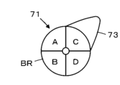
- the breast schematic diagram generating unit 65 generates a breast schematic diagram (also called a schema or body mark) 71 as shown in Fig. 13, for example.
- the breast schematic diagram 71 shown in Fig. 13 is a schematic representation of the left breast as seen from the front, and has a circular breast region BR and a substantially triangular axillary region 73 which represents the axilla and extends diagonally upward from the breast region BR.
- the breast region BR is divided into four regions, an inner upper region A, an inner lower region B, an outer upper region C, and an outer lower region D of the breast, and the axillary region 73 is connected to the upper left diagonal part of the outer upper region C. It should be noted that by flipping the breast schematic diagram 71 shown in FIG. 13 from left to right, a breast schematic diagram that typically represents the right breast can be obtained.
- the breast schematic diagram generation unit 65 uses the breast area BR divided into four areas, namely, an inner upper area A, an inner lower area B, an outer upper area C, and an outer lower area D, to generate a breast schematic diagram 71 in which a number of designated locations for placing the ultrasound probe 1 to capture ultrasound images are each plotted with a probe mark 74, as shown in Figure 14, and displays the diagram on the monitor 23. 14, probe marks 74 are plotted in all four regions obtained by dividing the breast region BR.
- the probe marks 74 are represented by line segments having a set length, and can indicate not only the positions of the multiple locations to which the ultrasonic probe 1 is applied, but also the orientation of the ultrasonic probe 1 to be applied to each location, depending on the orientation of the line segments.
- the first category determination unit 25 determines the GTC category of the subject's breast based on each of the multiple ultrasound images taken at multiple locations defined by the breast schematic diagram 71, and the category output unit 26 outputs the GTC category determined by the first category determination unit 25.
- a breast schematic diagram 71 as shown in Fig. 14 is generated by the breast schematic diagram generating unit 65 and displayed on the monitor 23 via the display control unit 22.
- probe marks 74 are plotted in all of the four regions obtained by dividing the breast region BR.
- step S22 the user checks the schematic diagram 71 of the breast displayed on the monitor 23, and takes an ultrasound image in accordance with the probe mark 74 plotted in one of the four regions. That is, the ultrasound probe 1 is placed against the subject's breast in the position and orientation indicated by the probe mark 74, and in this state, transmission and reception of ultrasound waves is started from the multiple transducers of the transducer array 11, and ultrasound echoes from within the subject's breast are received by the multiple transducers of the transducer array 11.
- Steps S1 to S5 following step S22 are the same as steps S1 to S5 in the flowchart in embodiment 1 shown in FIG. 6.
- step S1 an ultrasound image is acquired, in step S2, the ultrasound image is displayed on the monitor 23, and when it is determined in step S3 that there is an instruction to determine the GTC category, in step S4, the first category determination unit 25 determines the GTC category in the subject's breast based on the ultrasound image, and in step S4, the category output unit 26 outputs the GTC category.
- step S23 it is determined whether or not imaging of ultrasound images at the multiple determined locations has been completed.
- imaging according to only the first probe mark 74 out of the four probe marks 74 plotted on the schematic diagram 71 of the breast has been completed, and imaging according to the remaining three probe marks 74 has not been performed. Therefore, it is determined that imaging at the multiple locations has not yet been completed, and the process returns from step S23 to step S22.
- step S22 imaging is performed according to the second probe mark 74, and in the subsequent steps S1 to S5, the GTC category is determined and output based on the ultrasound image acquired according to the second probe mark 74, and then in step S23, it is determined whether imaging at multiple locations has ended. Similarly, step S22, steps S1 to S5, and step S23 are repeated until the ultrasonic images of all four probe marks 74 plotted on the schematic diagram 71 of the breast are taken.
- step S23 when it is determined in step S23 that the capturing of ultrasonic images for all four probe marks 74 has been completed, the series of processes is completed. As a result, the GTC category is determined and output at each of the four locations corresponding to the four probe marks 74 on the schematic diagram 71 of the breast.
- the accuracy of breast cancer risk estimation in the subject's mammary gland region M is improved, making it possible to perform a more reliable diagnosis.
- the probe marks 74 are plotted in all four regions into which the breast region BR is divided, but the probe marks 74 may be plotted in two or more of the four regions, rather than in all four regions. Furthermore, the number of regions into which the breast region BR is divided is not limited to four, and the breast region BR may be divided into two regions or eight regions, for example.
- areas such as the inner upper region A, the inner lower region B, the outer upper region C, and the outer lower region D in a schematic diagram 71 of the breast may be specified, and the user may take an ultrasound image at any position within the specified area.
- the number of divided areas in the breast schematic diagram 71, the number of plotted probe marks 74, etc. may be automatically set by the breast schematic diagram generating unit 65 under the control of the main body control unit 27C, or may be manually set by the user via the input device 28.
Landscapes
- Health & Medical Sciences (AREA)
- Life Sciences & Earth Sciences (AREA)
- Engineering & Computer Science (AREA)
- Heart & Thoracic Surgery (AREA)
- Molecular Biology (AREA)
- Biophysics (AREA)
- Nuclear Medicine, Radiotherapy & Molecular Imaging (AREA)
- Pathology (AREA)
- Radiology & Medical Imaging (AREA)
- Biomedical Technology (AREA)
- Veterinary Medicine (AREA)
- Medical Informatics (AREA)
- Physics & Mathematics (AREA)
- Surgery (AREA)
- Animal Behavior & Ethology (AREA)
- General Health & Medical Sciences (AREA)
- Public Health (AREA)
- Physiology (AREA)
- Computer Vision & Pattern Recognition (AREA)
- Computer Networks & Wireless Communication (AREA)
- Ultra Sonic Daignosis Equipment (AREA)
- Computer Graphics (AREA)
- General Engineering & Computer Science (AREA)
Priority Applications (3)
| Application Number | Priority Date | Filing Date | Title |
|---|---|---|---|
| EP23903283.2A EP4635422A4 (en) | 2022-12-15 | 2023-11-29 | ULTRASONIC DIAGNOSTIC DEVICE AND METHOD FOR CONTROLLING ULTRASONIC DIAGNOSTIC DEVICES |
| JP2024564265A JPWO2024127992A1 (https=) | 2022-12-15 | 2023-11-29 | |
| US19/205,773 US20250268561A1 (en) | 2022-12-15 | 2025-05-12 | Ultrasonic diagnostic apparatus and method of controlling ultrasonic diagnostic apparatus |
Applications Claiming Priority (2)
| Application Number | Priority Date | Filing Date | Title |
|---|---|---|---|
| JP2022-200197 | 2022-12-15 | ||
| JP2022200197 | 2022-12-15 |
Related Child Applications (1)
| Application Number | Title | Priority Date | Filing Date |
|---|---|---|---|
| US19/205,773 Continuation US20250268561A1 (en) | 2022-12-15 | 2025-05-12 | Ultrasonic diagnostic apparatus and method of controlling ultrasonic diagnostic apparatus |
Publications (1)
| Publication Number | Publication Date |
|---|---|
| WO2024127992A1 true WO2024127992A1 (ja) | 2024-06-20 |
Family
ID=91484830
Family Applications (1)
| Application Number | Title | Priority Date | Filing Date |
|---|---|---|---|
| PCT/JP2023/042710 Ceased WO2024127992A1 (ja) | 2022-12-15 | 2023-11-29 | 超音波診断装置および超音波診断装置の制御方法 |
Country Status (4)
| Country | Link |
|---|---|
| US (1) | US20250268561A1 (https=) |
| EP (1) | EP4635422A4 (https=) |
| JP (1) | JPWO2024127992A1 (https=) |
| WO (1) | WO2024127992A1 (https=) |
Families Citing this family (1)
| Publication number | Priority date | Publication date | Assignee | Title |
|---|---|---|---|---|
| CN120549537A (zh) * | 2024-02-29 | 2025-08-29 | 通用电气精准医疗有限责任公司 | 乳房密度的量化方法和超声成像系统 |
Citations (8)
| Publication number | Priority date | Publication date | Assignee | Title |
|---|---|---|---|---|
| US20170221201A1 (en) * | 2016-01-28 | 2017-08-03 | Taihao Medical Inc. | Medical image processing apparatus and breast image processing method thereof |
| JP2019193788A (ja) * | 2018-04-27 | 2019-11-07 | キヤノンメディカルシステムズ株式会社 | 医用情報処理システム及び医用情報処理プログラム |
| JP2020018694A (ja) | 2018-08-02 | 2020-02-06 | 株式会社日立製作所 | 超音波診断装置及び超音波画像処理方法 |
| EP3852054A1 (en) * | 2020-01-16 | 2021-07-21 | Koninklijke Philips N.V. | Method and system for automatically detecting anatomical structures in a medical image |
| JP2021533945A (ja) * | 2018-08-31 | 2021-12-09 | セノ メディカル インストルメンツ,インク. | 超音波及び/又は光音響(oa/us)特徴に基づいて癌分子サブタイプを決定するための方法及びシステム |
| WO2022044654A1 (ja) * | 2020-08-27 | 2022-03-03 | 富士フイルム株式会社 | 超音波診断装置および超音波診断装置の制御方法 |
| JP2022542209A (ja) * | 2019-07-31 | 2022-09-30 | ホロジック, インコーポレイテッド | 臨床ワークフローの判断を自動化し、優先読み取りインジケータを生成するためのシステムおよび方法 |
| WO2022234742A1 (ja) * | 2021-05-06 | 2022-11-10 | 富士フイルム株式会社 | 表示処理装置、方法及びプログラム |
Family Cites Families (1)
| Publication number | Priority date | Publication date | Assignee | Title |
|---|---|---|---|---|
| JP6736864B2 (ja) * | 2015-10-09 | 2020-08-05 | コニカミノルタ株式会社 | 超音波画像診断装置 |
-
2023
- 2023-11-29 EP EP23903283.2A patent/EP4635422A4/en active Pending
- 2023-11-29 JP JP2024564265A patent/JPWO2024127992A1/ja active Pending
- 2023-11-29 WO PCT/JP2023/042710 patent/WO2024127992A1/ja not_active Ceased
-
2025
- 2025-05-12 US US19/205,773 patent/US20250268561A1/en active Pending
Patent Citations (8)
| Publication number | Priority date | Publication date | Assignee | Title |
|---|---|---|---|---|
| US20170221201A1 (en) * | 2016-01-28 | 2017-08-03 | Taihao Medical Inc. | Medical image processing apparatus and breast image processing method thereof |
| JP2019193788A (ja) * | 2018-04-27 | 2019-11-07 | キヤノンメディカルシステムズ株式会社 | 医用情報処理システム及び医用情報処理プログラム |
| JP2020018694A (ja) | 2018-08-02 | 2020-02-06 | 株式会社日立製作所 | 超音波診断装置及び超音波画像処理方法 |
| JP2021533945A (ja) * | 2018-08-31 | 2021-12-09 | セノ メディカル インストルメンツ,インク. | 超音波及び/又は光音響(oa/us)特徴に基づいて癌分子サブタイプを決定するための方法及びシステム |
| JP2022542209A (ja) * | 2019-07-31 | 2022-09-30 | ホロジック, インコーポレイテッド | 臨床ワークフローの判断を自動化し、優先読み取りインジケータを生成するためのシステムおよび方法 |
| EP3852054A1 (en) * | 2020-01-16 | 2021-07-21 | Koninklijke Philips N.V. | Method and system for automatically detecting anatomical structures in a medical image |
| WO2022044654A1 (ja) * | 2020-08-27 | 2022-03-03 | 富士フイルム株式会社 | 超音波診断装置および超音波診断装置の制御方法 |
| WO2022234742A1 (ja) * | 2021-05-06 | 2022-11-10 | 富士フイルム株式会社 | 表示処理装置、方法及びプログラム |
Non-Patent Citations (3)
| Title |
|---|
| LEE SU HYUN, MOON WOO KYUNG: "Glandular Tissue Component on Breast Ultrasound in Dense Breasts: A New Imaging Biomarker for Breast Cancer Risk", KOREAN JOURNAL OF RADIOLOGY : OFFICIAL JOURNAL OF THE KOREAN RADIOLOGICAL SOCIETY, KOREA (SOUTH), vol. 23, no. 6, 1 January 2022 (2022-01-01), pages 574, XP093181359, ISSN: 1229-6929, DOI: 10.3348/kjr.2022.0099 * |
| See also references of EP4635422A1 |
| SU HYUN LEE ET AL.: "Glandular Tissue Component and Breast Cancer Risk in Mammographically Dense Breasts at Screening Breast US", RADIOLOGY, vol. 301, 1 October 2021 (2021-10-01), XP093036140, DOI: 10.1148/radiol.2021210367 |
Also Published As
| Publication number | Publication date |
|---|---|
| US20250268561A1 (en) | 2025-08-28 |
| EP4635422A4 (en) | 2026-03-25 |
| JPWO2024127992A1 (https=) | 2024-06-20 |
| EP4635422A1 (en) | 2025-10-22 |
Similar Documents
| Publication | Publication Date | Title |
|---|---|---|
| US9468418B2 (en) | Ultrasonic diagnostic apparatus, ultrasonic image display apparatus, and ultrasonic image display method | |
| EP4186437B1 (en) | Ultrasound image analysis apparatus, ultrasound diagnostic apparatus, and control method for ultrasound image analysis apparatus | |
| CN115279275A (zh) | 超声诊断设备及其操作方法 | |
| US20250352169A1 (en) | Ultrasonic diagnostic apparatus and method of controlling ultrasonic diagnostic apparatus | |
| US20250268561A1 (en) | Ultrasonic diagnostic apparatus and method of controlling ultrasonic diagnostic apparatus | |
| US20260000381A1 (en) | Ultrasound diagnostic apparatus and method of controlling ultrasound diagnostic apparatus | |
| JP2023182996A (ja) | 超音波診断装置および超音波診断装置の制御方法 | |
| JP7712189B2 (ja) | 超音波画像分析装置、超音波診断装置および超音波画像分析装置の制御方法 | |
| JP7560273B2 (ja) | 医用画像診断装置及び医用画像処理装置 | |
| WO2023050034A1 (zh) | 一种超声成像设备及其诊断报告的生成方法 | |
| JP7811149B2 (ja) | 画像表示装置および画像表示装置の制御方法 | |
| US12508004B2 (en) | Ultrasound diagnostic apparatus and control method of ultrasound diagnostic apparatus | |
| US20250378958A1 (en) | Ultrasonic diagnostic apparatus and method of controlling ultrasonic diagnostic apparatus | |
| US20260000382A1 (en) | Ultrasonic diagnostic apparatus and method of controlling ultrasonic diagnostic apparatus | |
| US20250387097A1 (en) | Ultrasound diagnostic apparatus and method of controlling ultrasound diagnostic apparatus | |
| JP2021053200A (ja) | 超音波診断装置、超音波診断方法および超音波診断プログラム | |
| EP4527314B1 (en) | Ultrasound diagnostic apparatus and control method of ultrasound diagnostic apparatus | |
| CN111281423A (zh) | 一种超声图像优化方法和超声成像设备 |
Legal Events
| Date | Code | Title | Description |
|---|---|---|---|
| 121 | Ep: the epo has been informed by wipo that ep was designated in this application |
Ref document number: 23903283 Country of ref document: EP Kind code of ref document: A1 |
|
| WWE | Wipo information: entry into national phase |
Ref document number: 2024564265 Country of ref document: JP |
|
| WWE | Wipo information: entry into national phase |
Ref document number: 2023903283 Country of ref document: EP |
|
| NENP | Non-entry into the national phase |
Ref country code: DE |
|
| ENP | Entry into the national phase |
Ref document number: 2023903283 Country of ref document: EP Effective date: 20250715 |
|
| WWP | Wipo information: published in national office |
Ref document number: 2023903283 Country of ref document: EP |