WO2024127486A1 - 端末装置、及び情報処理装置 - Google Patents
端末装置、及び情報処理装置 Download PDFInfo
- Publication number
- WO2024127486A1 WO2024127486A1 PCT/JP2022/045792 JP2022045792W WO2024127486A1 WO 2024127486 A1 WO2024127486 A1 WO 2024127486A1 JP 2022045792 W JP2022045792 W JP 2022045792W WO 2024127486 A1 WO2024127486 A1 WO 2024127486A1
- Authority
- WO
- WIPO (PCT)
- Prior art keywords
- evaluation
- aerosol
- terminal device
- information
- heating
- Prior art date
- Legal status (The legal status is an assumption and is not a legal conclusion. Google has not performed a legal analysis and makes no representation as to the accuracy of the status listed.)
- Ceased
Links
Images


Classifications
-
- A—HUMAN NECESSITIES
- A24—TOBACCO; CIGARS; CIGARETTES; SIMULATED SMOKING DEVICES; SMOKERS' REQUISITES
- A24F—SMOKERS' REQUISITES; MATCH BOXES; SIMULATED SMOKING DEVICES
- A24F40/00—Electrically operated smoking devices; Component parts thereof; Manufacture thereof; Maintenance or testing thereof; Charging means specially adapted therefor
- A24F40/50—Control or monitoring
-
- A—HUMAN NECESSITIES
- A24—TOBACCO; CIGARS; CIGARETTES; SIMULATED SMOKING DEVICES; SMOKERS' REQUISITES
- A24F—SMOKERS' REQUISITES; MATCH BOXES; SIMULATED SMOKING DEVICES
- A24F40/00—Electrically operated smoking devices; Component parts thereof; Manufacture thereof; Maintenance or testing thereof; Charging means specially adapted therefor
- A24F40/65—Devices with integrated communication means, e.g. wireless communication means
-
- A—HUMAN NECESSITIES
- A24—TOBACCO; CIGARS; CIGARETTES; SIMULATED SMOKING DEVICES; SMOKERS' REQUISITES
- A24F—SMOKERS' REQUISITES; MATCH BOXES; SIMULATED SMOKING DEVICES
- A24F40/00—Electrically operated smoking devices; Component parts thereof; Manufacture thereof; Maintenance or testing thereof; Charging means specially adapted therefor
- A24F40/50—Control or monitoring
- A24F40/57—Temperature control
-
- G—PHYSICS
- G06—COMPUTING OR CALCULATING; COUNTING
- G06Q—INFORMATION AND COMMUNICATION TECHNOLOGY [ICT] SPECIALLY ADAPTED FOR ADMINISTRATIVE, COMMERCIAL, FINANCIAL, MANAGERIAL OR SUPERVISORY PURPOSES; SYSTEMS OR METHODS SPECIALLY ADAPTED FOR ADMINISTRATIVE, COMMERCIAL, FINANCIAL, MANAGERIAL OR SUPERVISORY PURPOSES, NOT OTHERWISE PROVIDED FOR
- G06Q50/00—Information and communication technology [ICT] specially adapted for implementation of business processes of specific business sectors, e.g. utilities or tourism
- G06Q50/10—Services
-
- A—HUMAN NECESSITIES
- A24—TOBACCO; CIGARS; CIGARETTES; SIMULATED SMOKING DEVICES; SMOKERS' REQUISITES
- A24F—SMOKERS' REQUISITES; MATCH BOXES; SIMULATED SMOKING DEVICES
- A24F40/00—Electrically operated smoking devices; Component parts thereof; Manufacture thereof; Maintenance or testing thereof; Charging means specially adapted therefor
- A24F40/20—Devices using solid inhalable precursors
Definitions
- the present invention relates to a terminal device and an information processing device.
- inhalation devices such as electronic cigarettes and nebulizers
- inhalation devices generate aerosol imparted with flavor components using a substrate that includes an aerosol source for generating aerosol and a flavor source for imparting flavor components to the generated aerosol.
- Users can taste the flavor by inhaling the aerosol imparted with flavor components generated by the inhalation device.
- the action of a user inhaling an aerosol is hereinafter also referred to as a puff or a puffing action.
- Patent Document 1 discloses the configuration of a base material that can improve the smoking taste. Furthermore, the following Patent Document 1 discloses an evaluation of the smoking taste in examples of multiple base materials.
- Patent Document 1 specialized equipment was used in a laboratory, and the smoking taste was evaluated by a limited number of evaluators.
- the present disclosure has been made in light of the above problems, and the purpose of the present disclosure is to provide a mechanism that makes it easier to evaluate smoking taste.
- a terminal device includes a control unit that sets an evaluation period during which an evaluation of the taste of the aerosol generated by the inhalation device can be set based on information regarding the generation of aerosol obtained from the inhalation device that generates aerosol by heating an aerosol source contained in a substrate, and controls a process that accepts the user's setting of an evaluation of the taste during the set evaluation period.
- the control unit may set the evaluation period within a period during which the suction device is generating aerosol using one of the substrates.
- the control unit may set a plurality of evaluation periods, each of which may correspond to a plurality of timings at which the aerosol generated by the inhalation device is inhaled by the user.
- the suction device heats the aerosol source based on control information that defines parameters related to the temperature to which the aerosol source is heated, and the information related to the generation of the aerosol may include information for identifying the control information used by the suction device.
- the information regarding the generation of the aerosol may include information indicating that heating of the aerosol source has begun, and the control unit may set the evaluation period based on the elapsed time since heating of the aerosol source has begun.
- the control unit may also control a process for notifying a user of information indicating that it is time to inhale the aerosol generated by the suction device.
- the information regarding the generation of the aerosol includes information indicating that the aerosol generated by the suction device has been inhaled, and the control unit may set the evaluation period after the aerosol generated by the suction device has been inhaled.
- the control unit may also control a process of notifying a user of information indicating the progress of the process in which the suction device generates an aerosol.
- the control unit may accept settings for evaluating the smoking taste for multiple evaluation items during one evaluation period.
- the control unit may also control a process for notifying the user of information indicating the set smoking taste evaluation.
- an information processing device including a communication unit that receives evaluation result information including a user-specified evaluation of the smoking taste of an aerosol generated by an inhalation device heating an aerosol source contained in a substrate based on control information that specifies parameters related to the temperature at which the aerosol source is heated, and a control unit that compiles a plurality of pieces of evaluation result information including a user-specified evaluation of the smoking taste of an aerosol generated based on the same control information received by the communication unit.
- the control unit may aggregate multiple pieces of evaluation result information including the smoking taste evaluations set by multiple users.
- the control unit may also aggregate multiple pieces of evaluation result information including evaluations of smoking taste set by multiple users belonging to a specified user group or set in a specified environment.
- the control unit may also aggregate multiple pieces of evaluation result information, including evaluations of smoking taste set by a user for aerosols generated using the same type of base material.
- the present disclosure provides a mechanism that makes it easier to evaluate smoking taste.
- FIG. 1 is a diagram illustrating an example of the configuration of a system according to an embodiment of the present invention.
- FIG. 2 is a schematic diagram showing a configuration example of a suction device.
- FIG. 2 is a block diagram showing an example of the configuration of a terminal device according to the present embodiment.
- FIG. 4 is a diagram showing an example of a UI screen displayed by a terminal device according to the embodiment;
- FIG. 2 is a sequence diagram showing an example of a flow of processing executed in the system according to the present embodiment.
- FIG. 1 is a diagram showing an example of the configuration of a system 1 according to the present embodiment.
- the system 1 includes a plurality of suction devices 100 (100A and 100B), a plurality of terminal devices 200 (200A and 200B), and a server 300.
- the inhalation device 100 is a device that generates a substance to be inhaled by a user.
- the substance generated by the inhalation device 100 is described as an aerosol.
- the inhalation device 100 is an example of an aerosol generating device that generates an aerosol.
- the substance generated by the inhalation device 100 may be a gas.
- the inhalation device 100 can accommodate a stick-type substrate 150.
- the inhalation device 100 generates an aerosol using the accommodated stick-type substrate 150.
- the stick-type substrate 150 is an example of a substrate that contributes to the generation of an aerosol.
- the stick-type substrate 150 contains an aerosol source.
- the inhalation device 100 generates an aerosol by heating the accommodated stick-type substrate 150.
- the terminal device 200 is a device used by a user of the suction device 100.
- the terminal device 200 is associated with the suction device 100.
- the suction device 100 and the terminal device 200 may be paired in advance for wireless communication, or the fact that the users of the suction device 100 and the terminal device 200 are the same may be registered in advance in the server 300.
- the terminal device 200 may be any device such as a smartphone, a tablet terminal, a wearable device, or a PC (Personal Computer).
- the terminal device 200 may be a charger that charges the suction device 100.
- the server 300 is an information processing device that manages information on each device included in the system 1.
- the server 300 communicates with the terminal device 200 via the network 900.
- the server 300 communicates indirectly with the suction device 100 via the terminal device 200.
- the server 300 may perform various processes based on information collected from the suction device 100 via the terminal device 200.
- the server 300 may perform various processes based on user operations performed on the terminal device 200.
- System 1 includes multiple suction devices 100 and multiple terminal devices 200 used by multiple users.
- a user who uses suction device 100A and terminal device 200A is also referred to as user A.
- a user who uses suction device 100B and terminal device 200B is also referred to as user B.
- FIG. 2 is a schematic diagram showing a configuration example of the suction device 100.
- the suction device 100 includes a power supply unit 111, a sensor unit 112, a notification unit 113, a storage unit 114, a communication unit 115, a control unit 116, a heating unit 121, a storage unit 140, and a heat insulating unit 144.
- the power supply unit 111 stores power.
- the power supply unit 111 supplies power to each component of the suction device 100 under the control of the control unit 116.
- the power supply unit 111 may be configured, for example, by a rechargeable battery such as a lithium ion secondary battery.
- the sensor unit 112 acquires various information related to the suction device 100.
- the sensor unit 112 is configured with a pressure sensor such as a condenser microphone, a flow sensor, or a temperature sensor, and acquires values associated with suction by the user.
- the sensor unit 112 is configured with an input device such as a button or switch that accepts information input from the user.
- the notification unit 113 notifies the user of information.
- the notification unit 113 is composed of, for example, a light-emitting device that emits light, a display device that displays an image, a sound output device that outputs sound, or a vibration device that vibrates.
- the storage unit 114 stores various information for the operation of the suction device 100.
- the storage unit 114 is configured, for example, from a non-volatile storage medium such as a flash memory.
- the communication unit 115 is a communication interface capable of performing communication conforming to any wired or wireless communication standard.
- Such communication standards may include, for example, standards using Wi-Fi (registered trademark), Bluetooth (registered trademark), BLE (Bluetooth Low Energy (registered trademark)), NFC (Near Field Communication), or LPWA (Low Power Wide Area).
- the control unit 116 functions as an arithmetic processing unit and a control unit, and controls the overall operation of the suction device 100 in accordance with various programs.
- the control unit 116 is realized by an electronic circuit such as a CPU (Central Processing Unit) or a microprocessor.
- the storage section 140 has an internal space 141 and holds the stick-shaped substrate 150 while storing a part of the stick-shaped substrate 150 in the internal space 141.
- the storage section 140 has an opening 142 that connects the internal space 141 to the outside, and stores the stick-shaped substrate 150 inserted into the internal space 141 through the opening 142.
- the storage section 140 is a cylindrical body with the opening 142 and the bottom 143 as the bottom surface, and defines a columnar internal space 141.
- An air flow path that supplies air to the internal space 141 is connected to the storage section 140.
- An air inlet hole which is an air inlet to the air flow path, is arranged, for example, on the side of the suction device 100.
- An air outlet hole which is an air outlet from the air flow path to the internal space 141, is arranged, for example, on the bottom 143.
- the stick-type substrate 150 includes a substrate portion 151 and a mouthpiece portion 152.
- the substrate portion 151 includes an aerosol source.
- the aerosol source includes a flavor component derived from tobacco or non-tobacco.
- the aerosol source may include a medicine.
- the aerosol source may be, for example, a liquid such as a polyhydric alcohol such as glycerin and propylene glycol, and water, which includes a flavor component derived from tobacco or non-tobacco, or may be a solid containing a flavor component derived from tobacco or non-tobacco.
- the stick-type substrate 150 When the stick-type substrate 150 is held in the storage portion 140, at least a part of the substrate portion 151 is stored in the internal space 141, and at least a part of the mouthpiece portion 152 protrudes from the opening 142.
- the heating unit 121 generates aerosol by heating the aerosol source and atomizing the aerosol source.
- the heating unit 121 is configured in a film shape and is arranged to cover the outer periphery of the storage unit 140.
- the heating unit 121 generates heat, the substrate unit 151 of the stick-shaped substrate 150 is heated from the outer periphery, and an aerosol is generated.
- the heating unit 121 generates heat when power is supplied from the power supply unit 111.
- power may be supplied when the sensor unit 112 detects that the user has started inhaling and/or that specific information has been input. Power supply may be stopped when the sensor unit 112 detects that the user has stopped inhaling and/or that specific information has been input.
- the insulating section 144 prevents heat transfer from the heating section 121 to other components.
- the insulating section 144 is made of a vacuum insulating material or an aerogel insulating material.
- the configuration of the suction device 100 is not limited to the above, and various configurations such as those exemplified below are possible.
- the heating unit 121 may be configured in a blade shape and disposed so as to protrude from the bottom 143 of the storage unit 140 into the internal space 141. In that case, the blade-shaped heating unit 121 is inserted into the substrate 151 of the stick-shaped substrate 150 and heats the substrate 151 of the stick-shaped substrate 150 from the inside. As another example, the heating unit 121 may be disposed so as to cover the bottom 143 of the storage unit 140. Furthermore, the heating unit 121 may be configured as a combination of two or more of a first heating unit that covers the outer periphery of the storage unit 140, a blade-shaped second heating unit, and a third heating unit that covers the bottom 143 of the storage unit 140.
- the storage unit 140 may include an opening/closing mechanism such as a hinge that opens and closes a portion of the outer shell that forms the internal space 141. The storage unit 140 may then open and close the outer shell to accommodate the stick-shaped substrate 150 inserted into the internal space 141 while clamping it.
- the heating unit 121 may be provided at the clamping location in the storage unit 140, and may heat the stick-shaped substrate 150 while pressing it.
- the means for atomizing the aerosol source is not limited to heating by the heating unit 121.
- the means for atomizing the aerosol source may be induction heating.
- the suction device 100 has at least an electromagnetic induction source such as a coil that generates a magnetic field, instead of the heating unit 121.
- a susceptor that generates heat by induction heating may be provided in the suction device 100, or may be included in the stick-shaped substrate 150.
- the input unit 210 has a function of accepting input of various information.
- the input unit 210 may include an input device that accepts input of information from a user. Examples of the input device include a button, a keyboard, a touch panel, and a microphone.
- the input unit 210 may also include various sensors such as an image sensor.
- the output unit 220 has a function of outputting information.
- the output unit 220 may include an output device that outputs information to the user.
- Examples of output devices include a display device that displays information, a light-emitting device that emits light, a vibration device that vibrates, and a sound output device that outputs sound.
- An example of a display device is a display.
- An example of a light-emitting device is an LED (Light Emitting Diode).
- An example of a vibration device is an eccentric motor.
- An example of a sound output device is a speaker.
- the output unit 220 notifies the user of the information by outputting the information input from the control unit 260.
- the detection unit 230 has a function of detecting information related to the terminal device 200.
- the detection unit 230 may detect position information of the terminal device 200.
- the detection unit 230 receives a GNSS signal from a Global Navigation Satellite System (GNSS) satellite (for example, a GPS signal from a Global Positioning System (GPS) satellite) and detects position information consisting of the latitude and longitude of the device.
- GNSS Global Navigation Satellite System
- GPS Global Positioning System
- the detection unit 230 may detect the movement of the terminal device 200.
- the detection unit 230 includes a gyro sensor and an acceleration sensor, and detects angular velocity and acceleration.
- the communication unit 240 is a communication interface for transmitting and receiving information between the terminal device 200 and other devices.
- the communication unit 240 performs communication conforming to any wired or wireless communication standard.
- a communication standard for example, a standard using USB (Universal Serial Bus), Wi-Fi (registered trademark), Bluetooth (registered trademark), NFC (Near Field Communication), or LPWA (Low Power Wide Area) can be adopted.
- the storage unit 250 stores various types of information.
- the storage unit 250 is configured, for example, with a non-volatile storage medium such as a flash memory.
- the control unit 260 functions as a calculation processing unit or control unit, and controls the overall operation of the terminal device 200 according to various programs.
- the control unit 260 is realized by, for example, a CPU (Central Processing Unit) or an electronic circuit such as a microprocessor.
- the control unit 260 may include a ROM (Read Only Memory) that stores the programs and calculation parameters to be used, and a RAM (Random Access Memory) that temporarily stores parameters that change as appropriate.
- the terminal device 200 executes various processes based on the control of the control unit 260.
- the processing of information input by the input unit 210, the output of information by the output unit 220, the detection of information by the detection unit 230, the transmission and reception of information by the communication unit 240, and the storage and reading of information by the storage unit 250 are examples of processes controlled by the control unit 260.
- Other processes executed by the terminal device 200, such as the input of information to each component and processing based on information output from each component, are also controlled by the control unit 260.
- the functions of the control unit 260 may be realized using an application.
- the application may be pre-installed or may be downloaded.
- the functions of the control unit 260 may be realized by PWA (Progressive Web Apps).
- the server 300 includes a communication unit 310, a storage unit 320, and a control unit 330.
- the communication unit 310 is a communication interface for transmitting and receiving information between the server 300 and other devices.
- the communication unit 310 performs communication conforming to any wired or wireless communication standard.
- the storage unit 320 stores various information for the operation of the server 300.
- the storage unit 320 is configured with a non-volatile storage medium such as a hard disc drive (HDD) or a solid state drive (SSD).
- HDD hard disc drive
- SSD solid state drive
- the control unit 330 functions as a calculation processing device and a control device, and controls the overall operation of the server 300 according to various programs.
- the control unit 330 is realized by, for example, a CPU (Central Processing Unit) and electronic circuits such as a microprocessor.
- the control unit 330 may include a ROM (Read Only Memory) that stores the programs and calculation parameters to be used, and a RAM (Random Access Memory) that temporarily stores parameters that change as appropriate.
- the server 300 executes various processes based on the control of the control unit 330.
- the transmission and reception of information by the communication unit 310, and the storage and reading of information by the storage unit 320 are examples of processes controlled by the control unit 330.
- Other processes executed by the server 300 such as input of information to each component and processing based on information output from each component, are also controlled by the control unit 330.
- the control unit 116 controls the operation of the heating unit 121 based on the heating profile.
- the control of the operation of the heating unit 121 is achieved by controlling the power supply from the power supply unit 111 to the heating unit 121.
- the heating unit 121 heats the stick-shaped substrate 150 by using the power supplied from the power supply unit 111.
- the heating profile is control information for controlling the temperature at which the aerosol source is heated.
- the heating profile specifies parameters related to the temperature at which the aerosol source is heated.
- An example of the temperature at which the aerosol source is heated is the temperature of the heating unit 121.
- An example of the parameter related to the temperature at which the aerosol source is heated is the target value of the temperature of the heating unit 121 (hereinafter also referred to as the target temperature).
- the temperature of the heating unit 121 may be controlled to change according to the elapsed time from the start of heating.
- the heating profile includes information that specifies the time series transition of the target temperature.
- the heating profile may include parameters that specify the method of supplying power to the heating unit 121 (hereinafter also referred to as the power supply parameters).
- the power supply parameters include, for example, the voltage applied to the heating unit 121, ON/OFF of the power supply to the heating unit 121, or the feedback control method to be adopted.
- ON/OFF of the power supply to the heating unit 121 may be regarded as ON/OFF of the heating unit 121.
- the control unit 116 controls the operation of the heating unit 121 so that the temperature of the heating unit 121 (hereinafter also referred to as the actual temperature) changes in the same manner as the target temperature defined in the heating profile.
- the heating profile is typically designed to optimize the flavor experienced by the user when the user inhales the aerosol generated from the stick-shaped substrate 150. Therefore, by controlling the operation of the heating unit 121 based on the heating profile, the flavor experienced by the user can be optimized.
- the temperature control of the heating unit 121 can be realized, for example, by known feedback control.
- the feedback control may be, for example, PID control (Proportional-Integral-Differential Controller).
- the control unit 116 may supply power from the power supply unit 111 to the heating unit 121 in the form of pulses by pulse width modulation (PWM) or pulse frequency modulation (PFM).
- PWM pulse width modulation
- PFM pulse frequency modulation
- the control unit 116 can control the temperature of the heating unit 121 by adjusting the duty ratio or frequency of the power pulse in the feedback control.
- the control unit 116 may perform simple on/off control in the feedback control.
- control unit 116 may perform heating by the heating unit 121 until the actual temperature reaches the target temperature, interrupt heating by the heating unit 121 when the actual temperature reaches the target temperature, and resume heating by the heating unit 121 when the actual temperature becomes lower than the target temperature.
- the temperature of the heating section 121 can be quantified, for example, by measuring or estimating the electrical resistance value of the heating section 121 (more precisely, the heating resistor that constitutes the heating section 121). This is because the electrical resistance value of the heating resistor changes depending on the temperature.
- the electrical resistance value of the heating resistor can be estimated, for example, by measuring the amount of voltage drop in the heating resistor.
- the amount of voltage drop in the heating resistor can be measured by a voltage sensor that measures the potential difference applied to the heating resistor.
- the temperature of the heating section 121 can be measured by a temperature sensor such as a thermistor installed near the heating section 121.
- a heating session is a period during which power supply to the heating unit 121 is controlled based on a heating profile.
- the start of a heating session is the timing when heating based on the heating profile starts.
- the end of a heating session is the timing when a sufficient amount of aerosol is no longer generated.
- a heating session includes a pre-heating period in the first half and a puffable period in the second half.
- the puffable period is a period during which a sufficient amount of aerosol is expected to be generated.
- the pre-heating period is the period from the start of heating to the start of the puffable period. Heating performed during the pre-heating period is also referred to as pre-heating.
- the notification unit 113 may notify the user of information indicating the timing at which preheating will end. For example, the notification unit 113 may notify the user of information predicting the end of preheating before the end of preheating, or may notify the user of information indicating that preheating has ended at the timing at which preheating has ended.
- the notification to the user may be performed, for example, by lighting an LED or vibrating. The user may refer to such a notification and begin puffing immediately after preheating has ended.
- the notification unit 113 may notify the user of information indicating the timing when the puffing period will end. For example, the notification unit 113 may notify the user of information predicting the end of the puffing period before the end of the puffing period, or may notify the user of information indicating that the puffing period has ended at the timing when the puffing period has ended.
- the notification to the user may be performed, for example, by lighting an LED or vibrating. The user may refer to such a notification and continue puffing until the puffing period ends.
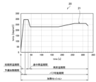
- FIG. 5 is a graph that shows a schematic example of a heating profile.
- the horizontal axis of graph 20 is time.
- the vertical axis of graph 20 is temperature.
- Line 21 shows the time series progression of the target temperature.
- a heating session may include an initial heating period, an intermediate temperature drop period, and a re-heating period, in that order.
- the initial heating period is a period in which the temperature of the heating unit 121 rises rapidly after the start of heating and is maintained at a high temperature.
- the intermediate temperature drop period is a period in which the temperature of the heating unit 121 drops after the initial heating period.
- the re-heating period is a period in which the temperature of the heating unit 121 rises again after the intermediate temperature drop period.
- the target temperature rises rapidly to around 300°C during the initial heating period, then drops to around 230°C during the intermediate temperature drop period, and then rises stepwise to around 260°C during the re-heating period.
- power supply to the heating unit 121 may be interrupted and heating may be turned off.
- the period from the start of heating to the middle of the initial temperature rise period is the pre-heating period, and the period from the middle of the initial temperature rise period to the end of the re-heating period is the puffable period.
- the terminal device 200 sets an evaluation period during which the evaluation of the smoking taste of the aerosol generated by the inhalation device 100 can be set based on information on the generation of the aerosol acquired from the inhalation device 100. For example, the terminal device 200 receives information on the generation of the aerosol source from the inhalation device 100 and sets the evaluation period based on the received information. Then, the terminal device 200 controls a process for accepting the setting of the evaluation of the smoking taste by the user during the set evaluation period. For example, the terminal device 200 displays a UI (User Interface) screen for setting the evaluation of the smoking taste on a touch panel and accepts a touch operation for setting the evaluation of the smoking taste during the evaluation period.
- UI User Interface
- the user can evaluate the smoking taste while using the inhalation device 100. Therefore, it is not necessary to use a dedicated device to evaluate the smoking taste, and it is possible to widely collect evaluations of the smoking taste from general users. In this way, it is possible to more easily carry out the evaluation of the smoking taste.
- the terminal device 200 sets the evaluation period during the period during which the inhalation device 100 is generating aerosol using one stick-shaped substrate 150. That is, the terminal device 200 sets the evaluation period within the heating session. In particular, it is desirable for the terminal device 200 to set the evaluation period within the puffable period. With this configuration, the user can set the evaluation of the smoking taste in real time while puffing during the heating session. This makes it possible to reduce the burden on the user compared to setting the evaluation of the smoking taste after the heating session has ended. Of course, the terminal device 200 may also set the evaluation period after the puffable period has ended. In that case, the user can set the evaluation of the smoking taste without rushing.
- the terminal device 200 sets multiple evaluation periods.
- each of the multiple evaluation periods corresponds to each of multiple timings at which the aerosol generated by the inhalation device 100 is inhaled by the user. That is, the terminal device 200 sets one evaluation period for one puff.
- the terminal device 200 sets a predetermined period that includes the timing at which the puff is performed (hereinafter also referred to as puff timing) as the evaluation period.
- puff timing a predetermined period that includes the timing at which the puff is performed
- the information on aerosol generation that the terminal device 200 acquires from the inhalation device 100 may include information indicating that heating of the aerosol source has started. For example, when the inhalation device 100 starts heating the stick-type substrate 150, it transmits information indicating that heating has started to the terminal device 200. In this case, the terminal device 200 sets the evaluation period based on the elapsed time since heating of the aerosol source started. For example, the terminal device 200 sets multiple puff timings within the puffable period, and determines the arrival of the set puff timing based on the elapsed time since heating of the stick-type substrate 150 started. Then, the terminal device 200 sets an evaluation period corresponding to the arrived puff timing. With this configuration, it is possible to appropriately set the evaluation period.
- the information related to aerosol generation that the terminal device 200 acquires from the inhalation device 100 may include information for identifying the heating profile used by the inhalation device 100 (hereinafter also referred to as a profile ID). For example, when the inhalation device 100 starts heating the stick-shaped substrate 150, it transmits the profile ID of the heating profile used for heating to the terminal device 200. In this case, the terminal device 200 sets the evaluation period based on the profile ID. The length of time of the heating session, the length of time from the start of heating to the start of the puffable period, and the puff timing may differ for each heating profile. In this regard, with this configuration, it is possible to appropriately set the evaluation period.
- the information on aerosol generation that the terminal device 200 acquires from the inhalation device 100 may include information indicating that the aerosol generated by the inhalation device 100 has been inhaled. For example, when the inhalation device 100 detects that the user has inhaled the aerosol (i.e., puffed), it transmits information indicating that a puff has been performed to the terminal device 200. Note that the inhalation device 100 determines that a puff has been performed when the sensor unit 112 acquires a value associated with inhalation by the user. In this case, the terminal device 200 may set an evaluation period after the timing at which a puff was performed. With this configuration, the terminal device 200 can set an evaluation period and accept the setting of a smoking taste evaluation only when a puff is actually performed near the puff timing.
- the terminal device 200 may notify the user of information indicating that it is time to inhale the aerosol generated by the inhalation device 100. For example, the terminal device 200 vibrates or emits light at the puff timing. With this configuration, the user can refer to the notification from the terminal device 200 and actually puff at the puff timing to set an evaluation of the smoking taste.
- FIG. 6 is a diagram showing an example of a UI screen displayed by the terminal device 200 according to this embodiment.
- the terminal device 200 accepts the setting of the smoking taste evaluation on the evaluation setting screen 30.
- the evaluation setting screen 30 includes an evaluation method explanation field 31, a progress display field 32, and evaluation setting fields 33 to 35.
- the evaluation method explanation field 31 is a field for informing the user of the evaluation method.
- the evaluation method explanation field 31 describes that the terminal device 200 will vibrate when the time to inhale the aerosol has arrived.
- the user can refer to this description and perform a puff at the timing when the terminal device 200 vibrates, and set an evaluation of the smoking taste.
- the progress display field 32 is a field for notifying the user of information indicating the progress of the process in which the inhalation device 100 generates an aerosol.
- the upper part of the progress display field 32 displays the progress of the heating session with the numerator being a number indicating which puff timing the next puff timing is, and the total number of puff timings being the denominator.
- the lower part of the progress display field 32 displays the progress of the heating session with the numerator being the elapsed time from the start of heating, and the duration of the heating session being the denominator. In the example shown in FIG.
- the progress display field 32 displays that the next puff timing of X out of a total of 15 puff timings is to arrive, and that the heating session has progressed to Y minutes and Z seconds out of the 5-minute heating session. The user can understand the progress of the heating session by referring to such displays.
- Evaluation setting fields 33 to 35 are fields for receiving the user's evaluation of the smoking experience.
- Evaluation setting field 33 is a field for receiving an evaluation of the smoking experience.
- Evaluation setting field 34 is a field for receiving an evaluation of the amount of smoke.
- Evaluation setting field 35 is a field for receiving an evaluation of the taste preference.
- buttons 33A to 33C which are UI elements for setting an evaluation of the draw.
- button 33A the terminal device 200 accepts the setting of an evaluation that the draw is strong
- button 33B the setting of an evaluation that the draw is just right
- button 33C the setting of an evaluation that the draw is weak.
- the evaluation setting field 34 for the amount of smoke includes buttons 34A to 34C, which are UI elements for setting an evaluation for the amount of smoke.
- buttons 34A to 34C which are UI elements for setting an evaluation for the amount of smoke.
- the taste preference evaluation setting field 35 includes buttons 35A and 35B, which are UI elements for setting an evaluation regarding taste preference.
- buttons 35A and 35B which are UI elements for setting an evaluation regarding taste preference.
- button 35A When button 35A is selected, the terminal device 200 accepts the setting of an evaluation that the taste is liked, and when button 35B is selected, the terminal device 200 accepts the setting of an evaluation that the taste is disliked.
- the terminal device 200 accepts the settings of the smoking taste evaluation for multiple evaluation items during one evaluation period. For example, each time a puff timing arrives, the terminal device 200 accepts the settings of the evaluation for the draw, the amount of smoke, and the taste preference during the evaluation period set according to the arrived puff timing.
- buttons 33B, 34A, and 35A are each selected as the evaluation of the smoking taste at the Xth puff timing.
- the user sets the evaluation that the draw is just right, the amount of smoke is large, and the taste is to the user's liking. With this configuration, the user can set the evaluation of the smoking taste from multiple perspectives.
- the terminal device 200 notifies the user of information indicating the smoking taste evaluation that has been set.
- the terminal device 200 displays the buttons 33B, 34A, and 35A selected by the user in a different manner from the other buttons.
- the terminal device 200 may display the button selected by the user in a different color from the other buttons.
- the above describes an example of a UI screen displayed by the terminal device 200.
- the terminal device 200 stores information indicating the set evaluation of the smoking taste (hereinafter, also referred to as evaluation result information).
- the evaluation result information includes an evaluation of the smoking taste for each puff timing.
- An example of the evaluation result information is shown in Table 1 below.
- the terminal device 200 may notify the user of the evaluation result information.
- the terminal device 200 may display the table shown in Table 1. With this configuration, the user can check the evaluation of the smoking taste that he or she set during the heating session all at once.
- the terminal device 200 stores a combination of identification information for identifying the heating profile used by the inhalation device 100 and information indicating the set smoking taste evaluation. More simply, the terminal device 200 stores the evaluation result information in association with the profile ID. With this configuration, it becomes possible to accumulate evaluation result information for each heating profile.
- the terminal device 200 transmits the stored evaluation result information to the server 300.
- the terminal device 200 transmits a combination of a profile ID and evaluation result information to the server 300.
- the terminal device 200 transmits the evaluation result information to the server 300 at a predetermined cycle or at any timing, such as when a predetermined number of evaluation result information has been accumulated.
- the server 300 can compile the collected evaluation result information and use it to improve the heating profile or the substrate.
- the server 300 receives and stores the evaluation result information, and controls the process of tabulating the stored evaluation result information. For example, the server 300 tabulates the evaluation result information for each puff timing and evaluation item. The server 300 may calculate the average value, weighted average value, or median value of the evaluation for each puff timing and evaluation item as the tabulation result.
- the server 300 compiles multiple pieces of evaluation result information, including the evaluation of the smoking taste set by the user for the aerosol generated based on the same heating profile. For example, the server 300 compiles evaluation result information associated with the same profile ID. With this configuration, it is possible to grasp the trend of the evaluation of the smoking taste for each heating profile. The compilation results can be used to improve the heating profile.
- the server 300 may aggregate multiple pieces of evaluation result information, including the evaluation of smoking taste set by multiple users. For example, the server 300 aggregates evaluation result information associated with the same profile ID collected from multiple users. With this configuration, it becomes possible to grasp the trends in the evaluation of smoking taste across multiple users.
- the server 300 may average the taste ratings set by multiple users for each puff timing and evaluation item.
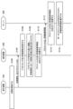
- FIG. 7 is a sequence diagram showing an example of a flow of a process executed in the system 1 according to the present embodiment.
- the suction device 100, the terminal device 200, and the server 300 are involved in this flow.
- the suction device 100 starts heating the stick-shaped substrate 150 based on the heating profile (step S102). For example, the suction device 100 starts heating when it detects that the stick-shaped substrate 150 has been inserted or that a specific button has been pressed.
- the suction device 100 transmits information indicating the start of heating and the profile ID of the heating profile to be used for heating to the terminal device 200 (step S104).
- the terminal device 200 When the terminal device 200 receives the information indicating the start of heating and the profile ID, it sets the puff timing and the evaluation period (step S106). For example, the terminal device 200 sets multiple puff timings based on the profile ID and the elapsed time from the start of heating, and sets multiple evaluation periods corresponding to the multiple puff timings.
- the terminal device 200 vibrates each time a puff timing occurs, and accepts the setting of an evaluation of the smoking taste during the evaluation period (step S108). For example, the terminal device 200 vibrates each time a puff timing occurs while displaying the evaluation setting screen shown in FIG. 6, and accepts the setting of an evaluation of the smoking taste.
- the terminal device 200 associates the profile ID with the evaluation result information and stores it (step S110).
- the terminal device 200 transmits the stored profile ID and evaluation result information to the server 300 (step S112).
- the server 300 When the server 300 receives the profile ID and the evaluation result information, it stores the received profile ID and evaluation result information in association with each other (step S114).
- the server 300 aggregates the evaluation result information associated with the same profile ID (step S116).
- the terminal device 200 sets the evaluation period based on information regarding aerosol generation acquired from the inhalation device 100, but the present disclosure is not limited to such an example.
- the terminal device 200 may set the evaluation period according to the interval between puffs performed by the user in the past. With such a configuration, it is possible to set an evaluation period that is suitable for the user's habits, such as a narrow or wide puff interval.
- the terminal device 200 sets the puff timing and sets an evaluation period corresponding to the set puff timing, but the present disclosure is not limited to such an example.
- the terminal device 200 does not need to set the puff timing in advance, and may set the evaluation period immediately after receiving information from the inhalation device 100 indicating that a puff has been performed.
- the server 300 may compile evaluation result information in which the puffing timing is similar.
- the terminal device 200 may accept evaluations as continuous values from 0 to 100. In this case, it becomes possible for the server 300 to more easily tally up the evaluations of the smoking taste.
- the server 300 may compile multiple pieces of evaluation result information, including evaluations of smoking taste set by multiple users belonging to a specific user group.
- the user group may be classified based on attributes such as age and gender.
- the terminal device 200 may associate information indicating the user attributes with the evaluation result information and transmit it to the server 300.
- the server 300 may then compile the evaluation result information associated with the attributes of the same user. With this configuration, it is possible to grasp the trends in evaluations of smoking taste for each user attribute.
- the server 300 may compile multiple pieces of evaluation result information, including evaluations of smoking taste set in a specific environment.
- the environment here refers to the environment in which the user puffed and set an evaluation of the smoking taste. Examples of environments include temperature, weather, humidity, location, and country.
- the terminal device 200 associates information indicating the environment with evaluation result information and transmits it to the server 300.
- the server 300 may then compile the evaluation result information associated with the same environment. With this configuration, it becomes possible to grasp the trends in evaluations of smoking taste for each environment.
- the server 300 may compile multiple pieces of evaluation result information, including evaluations of smoking taste set by the user for aerosols generated using the same type of stick-type substrate 150.
- the inhalation device 100 identifies the type of stick-type substrate 150 to be heated, and transmits identification information of the stick-type substrate 150 (hereinafter also referred to as a stick ID) to the terminal device 200.
- the terminal device 200 associates the stick ID with the evaluation result information and transmits them to the server 300.
- the server 300 then compiles the evaluation result information associated with the same stick ID. With this configuration, it is possible to grasp the trends in evaluations of smoking taste for each type of stick-type substrate 150.
- the parameter related to the temperature at which the aerosol source is heated is the target temperature of the heating unit 121, but the present disclosure is not limited to such an example.
- parameters related to the temperature at which the aerosol source is heated include the temperature itself of the heating unit 121 described in the above embodiment, as well as the electrical resistance value of the heating unit 121.
- examples of parameters related to the temperature at which the aerosol source is heated, as specified in the heating profile include target values such as the temperature of the susceptor or the electrical resistance value of the electromagnetic induction source.
- the suction device 100 may be configured as a so-called liquid atomization type aerosol generator that generates an aerosol by heating and atomizing an aerosol source as a liquid.
- the technology disclosed herein can also be applied to liquid atomization type aerosol generators.
- the setting of the smoking taste evaluation is accepted by the terminal device 200.
- the terminal device 200 accepting the setting of the smoking taste evaluation may refer to accepting the setting of the smoking taste evaluation via a native application installed on the terminal device 200.
- the terminal device 200 accepting the setting of the smoking taste evaluation may refer to accepting the setting of the smoking taste evaluation via a PWA (Progressive Web Apps) provided for the terminal device 200.
- the server 300 may accept the setting of the smoking taste evaluation via a PWA provided for the terminal device 200.
- the series of processes performed by each device described in this specification may be realized using software, hardware, or a combination of software and hardware.
- the programs constituting the software are stored in advance, for example, in a recording medium (more specifically, a non-transient storage medium readable by a computer) provided inside or outside each device.
- Each program is loaded into a RAM when executed by a computer that controls each device described in this specification, and executed by a processing circuit such as a CPU.
- the recording medium is, for example, a magnetic disk, an optical disk, a magneto-optical disk, a flash memory, etc.
- the computer program may be distributed, for example, via a network without using a recording medium.
- the computer may be an application-specific integrated circuit such as an ASIC, a general-purpose processor that executes functions by reading a software program, or a computer on a server used in cloud computing.
- ASIC application-specific integrated circuit
- ASIC application-specific integrated circuit
- CPU central processing unit
- CPU central processing unit
- server a server used in cloud computing.
- the series of processes performed by each device described in this specification may be distributed and processed by multiple computers.
- a control unit that sets an evaluation period during which an evaluation of the taste of the aerosol generated by the inhalation device can be set based on information regarding the generation of the aerosol obtained from the inhalation device that generates the aerosol by heating an aerosol source contained in a base material, and controls a process of accepting a user's setting of the evaluation of the taste during the set evaluation period;
- a terminal device comprising: (2) The control unit sets the evaluation period within a period during which the inhalation device generates an aerosol using one of the substrates. The terminal device described in (1).
- the control unit sets a plurality of the evaluation periods, Each of the plurality of evaluation periods corresponds to each of a plurality of timings at which the aerosol generated by the inhalation device is inhaled by the user.
- a terminal device according to (1) or (2).
- the inhalation device heats the aerosol source based on control information that defines parameters related to a temperature to which the aerosol source is heated; The information regarding the generation of the aerosol includes information for identifying the control information to be used by the inhalation device.
- a terminal device according to any one of (1) to (3).
- the control unit controls a process of storing a combination of information for identifying the control information used by the inhalation device and information indicating a set evaluation of the smoking taste. The terminal device described in (4).
- the information regarding the generation of the aerosol includes information indicating that heating of the aerosol source has been initiated; The control unit sets the evaluation period based on an elapsed time from when heating of the aerosol source is started. A terminal device according to any one of (1) to (5). (7) The control unit controls a process of notifying a user of information indicating that it is time to inhale the aerosol generated by the inhalation device. A terminal device according to any one of (1) to (6). (8) The information regarding the generation of the aerosol includes information indicating that the aerosol generated by the inhalation device has been inhaled, The control unit sets the evaluation period after the aerosol generated by the inhalation device is inhaled. A terminal device according to any one of (1) to (7).
- the control unit controls a process of notifying a user of information indicating a progress of a process of generating an aerosol by the inhalation device.
- a terminal device according to any one of (1) to (8).
- the control unit accepts settings for evaluating the smoking taste for a plurality of evaluation items during one of the evaluation periods.
- a terminal device according to any one of (1) to (9).
- the control unit controls a process of notifying a user of information indicating the set smoking taste evaluation.
- a communication unit that receives evaluation result information including an evaluation of a smoking taste set by a user for an aerosol generated by an inhalation device heating an aerosol source contained in a substrate based on control information that defines parameters related to a temperature at which the aerosol source is heated;
- a control unit that aggregates a plurality of pieces of evaluation result information including evaluations of smoking taste set by a user for the aerosol generated based on the same control information received by the communication unit;
- An information processing device comprising: (13) The control unit aggregates a plurality of pieces of evaluation result information including evaluations of smoking taste set by a plurality of users.
- the information processing device according to (12).
- the control unit compiles a plurality of pieces of evaluation result information including evaluations of smoking taste set by a plurality of users belonging to a predetermined user group or set in a predetermined environment.
- the information processing device according to (13).
- the control unit compiles a plurality of pieces of evaluation result information including evaluations of smoking taste set by a user for aerosols generated using the same type of base material.
- the information processing device according to any one of (12) to (14).
Landscapes
- Business, Economics & Management (AREA)
- Engineering & Computer Science (AREA)
- Tourism & Hospitality (AREA)
- Computer Networks & Wireless Communication (AREA)
- Marketing (AREA)
- Economics (AREA)
- General Health & Medical Sciences (AREA)
- Human Resources & Organizations (AREA)
- Health & Medical Sciences (AREA)
- Primary Health Care (AREA)
- Strategic Management (AREA)
- Physics & Mathematics (AREA)
- General Business, Economics & Management (AREA)
- General Physics & Mathematics (AREA)
- Theoretical Computer Science (AREA)
- Medicinal Preparation (AREA)
- Stored Programmes (AREA)
Priority Applications (5)
| Application Number | Priority Date | Filing Date | Title |
|---|---|---|---|
| KR1020257019465A KR20250107254A (ko) | 2022-12-13 | 2022-12-13 | 단말 장치 및 정보 처리 장치 |
| PCT/JP2022/045792 WO2024127486A1 (ja) | 2022-12-13 | 2022-12-13 | 端末装置、及び情報処理装置 |
| EP22968398.2A EP4623732A1 (en) | 2022-12-13 | 2022-12-13 | Terminal device and information processing device |
| JP2024563803A JPWO2024127486A1 (https=) | 2022-12-13 | 2022-12-13 | |
| TW112115815A TW202424862A (zh) | 2022-12-13 | 2023-04-27 | 終端裝置及資訊處理裝置 |
Applications Claiming Priority (1)
| Application Number | Priority Date | Filing Date | Title |
|---|---|---|---|
| PCT/JP2022/045792 WO2024127486A1 (ja) | 2022-12-13 | 2022-12-13 | 端末装置、及び情報処理装置 |
Publications (1)
| Publication Number | Publication Date |
|---|---|
| WO2024127486A1 true WO2024127486A1 (ja) | 2024-06-20 |
Family
ID=91484556
Family Applications (1)
| Application Number | Title | Priority Date | Filing Date |
|---|---|---|---|
| PCT/JP2022/045792 Ceased WO2024127486A1 (ja) | 2022-12-13 | 2022-12-13 | 端末装置、及び情報処理装置 |
Country Status (5)
| Country | Link |
|---|---|
| EP (1) | EP4623732A1 (https=) |
| JP (1) | JPWO2024127486A1 (https=) |
| KR (1) | KR20250107254A (https=) |
| TW (1) | TW202424862A (https=) |
| WO (1) | WO2024127486A1 (https=) |
Citations (8)
| Publication number | Priority date | Publication date | Assignee | Title |
|---|---|---|---|---|
| JP2001174450A (ja) * | 1999-12-21 | 2001-06-29 | Shiseido Co Ltd | 香りの評価方法及び香りの評価質問紙 |
| JP2017107516A (ja) * | 2015-12-12 | 2017-06-15 | 株式会社アルファTkg | 精油の選択プログラム |
| US20190380382A1 (en) * | 2018-06-18 | 2019-12-19 | Duo IQ Labs, LLC | Methods and systems for managing vapor distribution |
| US20200305511A1 (en) * | 2019-03-29 | 2020-10-01 | Loop Laboratories, LLC | Inhalant dispensing system and apparatus with binary dosing |
| JP6839181B2 (ja) | 2016-05-27 | 2021-03-03 | 日本たばこ産業株式会社 | 非燃焼型加熱喫煙物品用のたばこ充填物 |
| JP2022102721A (ja) * | 2020-12-25 | 2022-07-07 | 株式会社イノス・ジャポン | 化粧品開発サービス運営システム |
| JP2022169002A (ja) * | 2021-04-27 | 2022-11-09 | 日本たばこ産業株式会社 | 吸引装置、基材、制御方法、及び吸引システム |
| JP2022546912A (ja) * | 2019-09-05 | 2022-11-10 | ジェイティー インターナショナル エス.エイ. | エアロゾル生成装置のための加熱状態インジケータ及び加熱方法 |
-
2022
- 2022-12-13 EP EP22968398.2A patent/EP4623732A1/en active Pending
- 2022-12-13 JP JP2024563803A patent/JPWO2024127486A1/ja active Pending
- 2022-12-13 WO PCT/JP2022/045792 patent/WO2024127486A1/ja not_active Ceased
- 2022-12-13 KR KR1020257019465A patent/KR20250107254A/ko active Pending
-
2023
- 2023-04-27 TW TW112115815A patent/TW202424862A/zh unknown
Patent Citations (8)
| Publication number | Priority date | Publication date | Assignee | Title |
|---|---|---|---|---|
| JP2001174450A (ja) * | 1999-12-21 | 2001-06-29 | Shiseido Co Ltd | 香りの評価方法及び香りの評価質問紙 |
| JP2017107516A (ja) * | 2015-12-12 | 2017-06-15 | 株式会社アルファTkg | 精油の選択プログラム |
| JP6839181B2 (ja) | 2016-05-27 | 2021-03-03 | 日本たばこ産業株式会社 | 非燃焼型加熱喫煙物品用のたばこ充填物 |
| US20190380382A1 (en) * | 2018-06-18 | 2019-12-19 | Duo IQ Labs, LLC | Methods and systems for managing vapor distribution |
| US20200305511A1 (en) * | 2019-03-29 | 2020-10-01 | Loop Laboratories, LLC | Inhalant dispensing system and apparatus with binary dosing |
| JP2022546912A (ja) * | 2019-09-05 | 2022-11-10 | ジェイティー インターナショナル エス.エイ. | エアロゾル生成装置のための加熱状態インジケータ及び加熱方法 |
| JP2022102721A (ja) * | 2020-12-25 | 2022-07-07 | 株式会社イノス・ジャポン | 化粧品開発サービス運営システム |
| JP2022169002A (ja) * | 2021-04-27 | 2022-11-09 | 日本たばこ産業株式会社 | 吸引装置、基材、制御方法、及び吸引システム |
Non-Patent Citations (1)
| Title |
|---|
| See also references of EP4623732A1 |
Also Published As
| Publication number | Publication date |
|---|---|
| KR20250107254A (ko) | 2025-07-11 |
| TW202424862A (zh) | 2024-06-16 |
| JPWO2024127486A1 (https=) | 2024-06-20 |
| EP4623732A1 (en) | 2025-10-01 |
Similar Documents
| Publication | Publication Date | Title |
|---|---|---|
| CN113412132A (zh) | 汽化筒的汽雾定量供给平台 | |
| US20240423288A1 (en) | Information processing device, information processing method, and non-transitory computer readable medium | |
| US20250000170A1 (en) | Information processing device, information processing method, and non-transitory computer readable medium | |
| US20240306731A1 (en) | Control device, inhalation device, and control method | |
| EP4212045A1 (en) | Control method, inhalation device, terminal device, and program | |
| JP7713093B2 (ja) | システム及び情報処理方法 | |
| WO2024127486A1 (ja) | 端末装置、及び情報処理装置 | |
| EP4623733A1 (en) | Terminal device and control method | |
| WO2024127488A1 (ja) | 端末装置及び制御方法 | |
| TWI921655B (zh) | 終端裝置及控制方法 | |
| WO2024127503A1 (ja) | 情報処理装置、情報処理方法、及びプログラム | |
| EP4623734A1 (en) | Terminal device, information processing method, and program | |
| EP4635339A1 (en) | Information processing device, information processing method, and program | |
| WO2024127504A1 (ja) | 情報処理装置、情報処理方法、及びプログラム | |
| KR20250108714A (ko) | 단말 장치, 정보 처리 방법, 및 컴퓨터 판독 가능한 매체에 저장된 프로그램 | |
| US20240292903A1 (en) | Information processing device, information processing method, and non-transitory computer readable medium | |
| EP4285973A1 (en) | Control device, terminal device, and information processing method | |
| EP4627951A1 (en) | Information processing device, and information processing method | |
| EP4282293A1 (en) | Control device, terminal device, and information processing method | |
| WO2025154266A1 (ja) | 加熱情報設定方法、加熱情報設定システム、及びプログラム | |
| WO2023157122A1 (ja) | 情報処理装置、エアロゾル生成システム、及びプログラム |
Legal Events
| Date | Code | Title | Description |
|---|---|---|---|
| 121 | Ep: the epo has been informed by wipo that ep was designated in this application |
Ref document number: 22968398 Country of ref document: EP Kind code of ref document: A1 |
|
| WWE | Wipo information: entry into national phase |
Ref document number: 2024563803 Country of ref document: JP |
|
| WWE | Wipo information: entry into national phase |
Ref document number: 1020257019465 Country of ref document: KR |
|
| WWE | Wipo information: entry into national phase |
Ref document number: 2022968398 Country of ref document: EP |
|
| ENP | Entry into the national phase |
Ref document number: 2022968398 Country of ref document: EP Effective date: 20250626 |
|
| WWP | Wipo information: published in national office |
Ref document number: 1020257019465 Country of ref document: KR |
|
| NENP | Non-entry into the national phase |
Ref country code: DE |
|
| WWP | Wipo information: published in national office |
Ref document number: 2022968398 Country of ref document: EP |