WO2024122286A1 - 電気化学セル - Google Patents
電気化学セル Download PDFInfo
- Publication number
- WO2024122286A1 WO2024122286A1 PCT/JP2023/041059 JP2023041059W WO2024122286A1 WO 2024122286 A1 WO2024122286 A1 WO 2024122286A1 JP 2023041059 W JP2023041059 W JP 2023041059W WO 2024122286 A1 WO2024122286 A1 WO 2024122286A1
- Authority
- WO
- WIPO (PCT)
- Prior art keywords
- electrode layer
- metal plate
- flow path
- main surface
- electrical connection
- Prior art date
- Legal status (The legal status is an assumption and is not a legal conclusion. Google has not performed a legal analysis and makes no representation as to the accuracy of the status listed.)
- Ceased
Links
Images




Classifications
-
- C—CHEMISTRY; METALLURGY
- C25—ELECTROLYTIC OR ELECTROPHORETIC PROCESSES; APPARATUS THEREFOR
- C25B—ELECTROLYTIC OR ELECTROPHORETIC PROCESSES FOR THE PRODUCTION OF COMPOUNDS OR NON-METALS; APPARATUS THEREFOR
- C25B9/00—Cells or assemblies of cells; Constructional parts of cells; Assemblies of constructional parts, e.g. electrode-diaphragm assemblies; Process-related cell features
- C25B9/60—Constructional parts of cells
- C25B9/63—Holders for electrodes; Positioning of the electrodes
-
- H—ELECTRICITY
- H01—ELECTRIC ELEMENTS
- H01M—PROCESSES OR MEANS, e.g. BATTERIES, FOR THE DIRECT CONVERSION OF CHEMICAL ENERGY INTO ELECTRICAL ENERGY
- H01M8/00—Fuel cells; Manufacture thereof
- H01M8/02—Details
-
- H—ELECTRICITY
- H01—ELECTRIC ELEMENTS
- H01M—PROCESSES OR MEANS, e.g. BATTERIES, FOR THE DIRECT CONVERSION OF CHEMICAL ENERGY INTO ELECTRICAL ENERGY
- H01M8/00—Fuel cells; Manufacture thereof
- H01M8/02—Details
- H01M8/0202—Collectors; Separators, e.g. bipolar separators; Interconnectors
- H01M8/0204—Non-porous and characterised by the material
- H01M8/0206—Metals or alloys
-
- H—ELECTRICITY
- H01—ELECTRIC ELEMENTS
- H01M—PROCESSES OR MEANS, e.g. BATTERIES, FOR THE DIRECT CONVERSION OF CHEMICAL ENERGY INTO ELECTRICAL ENERGY
- H01M8/00—Fuel cells; Manufacture thereof
- H01M8/02—Details
- H01M8/0202—Collectors; Separators, e.g. bipolar separators; Interconnectors
- H01M8/0258—Collectors; Separators, e.g. bipolar separators; Interconnectors characterised by the configuration of channels, e.g. by the flow field of the reactant or coolant
-
- H—ELECTRICITY
- H01—ELECTRIC ELEMENTS
- H01M—PROCESSES OR MEANS, e.g. BATTERIES, FOR THE DIRECT CONVERSION OF CHEMICAL ENERGY INTO ELECTRICAL ENERGY
- H01M8/00—Fuel cells; Manufacture thereof
- H01M8/10—Fuel cells with solid electrolytes
- H01M8/12—Fuel cells with solid electrolytes operating at high temperature, e.g. with stabilised ZrO2 electrolyte
-
- H—ELECTRICITY
- H01—ELECTRIC ELEMENTS
- H01M—PROCESSES OR MEANS, e.g. BATTERIES, FOR THE DIRECT CONVERSION OF CHEMICAL ENERGY INTO ELECTRICAL ENERGY
- H01M8/00—Fuel cells; Manufacture thereof
- H01M8/10—Fuel cells with solid electrolytes
- H01M8/12—Fuel cells with solid electrolytes operating at high temperature, e.g. with stabilised ZrO2 electrolyte
- H01M8/1213—Fuel cells with solid electrolytes operating at high temperature, e.g. with stabilised ZrO2 electrolyte characterised by the electrode/electrolyte combination or the supporting material
- H01M8/1226—Fuel cells with solid electrolytes operating at high temperature, e.g. with stabilised ZrO2 electrolyte characterised by the electrode/electrolyte combination or the supporting material characterised by the supporting layer
-
- Y—GENERAL TAGGING OF NEW TECHNOLOGICAL DEVELOPMENTS; GENERAL TAGGING OF CROSS-SECTIONAL TECHNOLOGIES SPANNING OVER SEVERAL SECTIONS OF THE IPC; TECHNICAL SUBJECTS COVERED BY FORMER USPC CROSS-REFERENCE ART COLLECTIONS [XRACs] AND DIGESTS
- Y02—TECHNOLOGIES OR APPLICATIONS FOR MITIGATION OR ADAPTATION AGAINST CLIMATE CHANGE
- Y02E—REDUCTION OF GREENHOUSE GAS [GHG] EMISSIONS, RELATED TO ENERGY GENERATION, TRANSMISSION OR DISTRIBUTION
- Y02E60/00—Enabling technologies; Technologies with a potential or indirect contribution to GHG emissions mitigation
- Y02E60/30—Hydrogen technology
- Y02E60/50—Fuel cells
Definitions
- the present invention relates to an electrochemical cell.
- Patent Document 1 discloses a metal-supported electrochemical cell (electrolysis cell, fuel cell, etc.) that includes a metal plate with multiple communication holes formed therein, a cell body supported by the metal plate, and a flow path member that forms a gas flow path between the metal plate.
- the cell body has a first electrode layer and a second electrode layer formed on the metal plate, and an electrolyte layer disposed between the first electrode layer and the second electrode layer.
- the objective of the present invention is to provide an electrochemical cell that can suppress localized deterioration of the first electrode layer.
- the electrochemical cell according to the first aspect of the present invention comprises a metal plate, a cell body, a current collector, a conductive flow path member, and an electrical connection member.
- the metal plate has a first main surface, a second main surface, and a plurality of communication holes communicating with the first and second main surfaces.
- the cell body has a first electrode layer formed on the first main surface of the metal plate, a second electrode layer, and an electrolyte layer disposed between the first and second electrode layers.
- the current collector is disposed within the plurality of communication holes and has a plurality of first portions connected to the first electrode layer.
- the flow path member is joined to the second main surface and forms a gas flow path between the metal plate.
- the electrical connection member is disposed in the gas flow path and electrically connects at least one of the flow path member and the metal plate to the current collector.
- the electrochemical cell according to the second aspect of the present invention relates to the above-mentioned first aspect, and the electrical resistance of the first current route flowing between the first electrode layer and the flow path member via the current collector and the electrical connection member is smaller than the electrical resistance of the second current route flowing between the first electrode layer and the flow path member via the metal plate.
- the electrochemical cell according to the third aspect of the present invention is the electrochemical cell according to the second aspect, in which the electrical connection member is connected to the current collector and the flow path member by metal-metal connection, and the metal plate has a substrate and an oxide film covering the surface of the substrate.
- the electrochemical cell according to the fourth aspect of the present invention relates to any one of the first to third aspects, and the current collecting portion is formed in a layer on the second main surface of the metal plate and has a second portion connected to a plurality of first portions.
- the present invention provides an electrochemical cell that can suppress localized deterioration of the first electrode layer.
- FIG. 1 is a cross-sectional view of an electrolysis cell according to an embodiment.
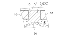
- FIG. 2 is a partially enlarged view of FIG.
- FIG. 11 is a schematic diagram of a current collecting part according to Modification 3.
- FIG. 11 is a schematic diagram of a current collecting part according to Modification 3.
- FIG. 11 is a schematic diagram of a current collecting part according to Modification 3.
- FIG. 11 is a schematic diagram of a current collecting part according to Modification 3.
- FIG. 13 is a schematic diagram of an electrical connection member according to a fourth modified example.
- FIG. 13 is a schematic diagram of an electrical connection member according to a fourth modified example.
- the electrolytic cell is an example of an electrochemical cell.
- a ceramic solid oxide electrolytic cell SOEC
- the solid oxide electrolytic cell will be abbreviated as "electrolytic cell.”
- FIG. 1 is a cross-sectional view of an electrolysis cell 1 according to an embodiment.
- FIG. 2 is an enlarged view of a portion of FIG. 1.
- the cell 1 includes a metal plate 10, a cell body 20, a current collecting portion 30, a flow path member 40, and an electrical connection member 50.
- the metal plate 10 supports the cell main body 20.
- the metal plate 10 is formed in a plate shape.
- the metal plate 10 may be flat or curved.
- the metal plate 10 may have any thickness as long as it can maintain the strength of the cell 1, and the thickness is not particularly limited, but may be, for example, 0.1 mm or more and 2.0 mm or less.
- the metal plate 10 has a first main surface 11, a second main surface 12, and a plurality of communication holes 13.
- a cell main body 20 is disposed on the first main surface 11 of the metal plate 10.
- the second main surface 12 of the metal plate 10 is provided on the opposite side to the first main surface 11.
- a second portion 32 of a current collector 30 (described later) is disposed on the second main surface 12 of the metal plate 10.
- a flow path member 40 is joined to the second main surface 12 of the metal plate 10.
- the metal plate 10 and the flow path member 40 are joined by a joint 60, as shown in FIG. 2.
- the multiple communication holes 13 are formed in a region corresponding to the hydrogen electrode layer 21 described later. Each communication hole 13 communicates with the first main surface 11 and the second main surface 12. A first portion 31 of the current collector 30 described later is disposed within each communication hole 13. In this embodiment, the first portion 31 fills the communication hole 13. Each communication hole 13 opens to the first main surface 11 and the second main surface 12, respectively. The opening of each communication hole 13 on the first main surface 11 side is covered by the hydrogen electrode layer 21. The opening of each communication hole 13 on the second main surface 12 side is covered by the second portion 32 of the current collector 30.
- the area of the communication hole 13 in plan view can be, for example, 0.00005 mm2 or more and 1 mm2 or less.
- the diameter of the communication hole 13 can be, for example, 10 ⁇ m or more and 1000 ⁇ m or less.
- the shape of the communication hole 13 in plan view may be rectangular.
- the communication holes 13 can be formed by mechanical processing (e.g., punching), laser processing, or chemical processing (e.g., etching).
- the metal plate 10 may be made of a porous metal having a mesh-like pore.
- the metal plate 10 is composed of a substrate 14 and an oxide film 15.
- the substrate 14 is made of a metal material.
- the substrate 14 is made of, for example, an alloy material containing Cr (chromium). Examples of such metal materials include Fe-Cr alloy steel (stainless steel, etc.) and Ni-Cr alloy steel.
- the Cr content in the metal plate 10 is not particularly limited, but can be 4% by mass or more and 30% by mass or less.
- the substrate 14 may contain Ti (titanium) and Zr (zirconium).
- the Ti content in the substrate 14 is not particularly limited, but may be 0.01 mol% or more and 1.0 mol% or less.
- the Zr content in the substrate 14 is not particularly limited, but may be 0.01 mol% or more and 0.4 mol% or less.
- the substrate 14 may contain Ti as TiO2 (titania) and may contain Zr as ZrO2 (zirconia).
- the oxide film 15 covers at least a portion of the surface of the substrate 14. In this embodiment, as shown in FIG. 2, the oxide film 15 covers the surface of the substrate 14 except for the area where the joint 60 is joined. Therefore, the oxide film 15 is interposed between the substrate 14 and the hydrogen electrode layer 21 described below, and between the substrate 14 and the current collector 30.
- the oxide film 15 can be composed of oxides of the constituent elements of the substrate 14.
- the oxide film 15 may contain chromium oxide as a main component. "Containing chromium oxide as a main component” means that chromium oxide accounts for 70% by weight or more of the oxide film 15.
- the thickness of the oxide film 15 is not particularly limited, but can be, for example, 0.1 ⁇ m or more and 20 ⁇ m or less.
- the oxide film 15 can be formed by applying a material paste to the surface of the substrate 14, but it can also be formed by leaving the substrate 14 in the air and allowing it to oxidize.
- the cell body 20 1, the cell body 20 is disposed on the first main surface 11 of the metal plate 10.
- the cell body 20 has a hydrogen electrode layer 21 (cathode), an electrolyte layer 22, a reaction prevention layer 23, and an oxygen electrode layer 24 (anode).
- the hydrogen electrode layer 21 is an example of a "first electrode layer” according to the present invention
- the oxygen electrode layer 24 is an example of a "second electrode layer” according to the present invention.
- the hydrogen electrode layer 21, electrolyte layer 22, reaction prevention layer 23, and oxygen electrode layer 24 are stacked in this order from the metal plate 10 side.
- the cell body 20 does not necessarily have to have the reaction prevention layer 23.
- the hydrogen electrode layer 21 is formed on the first main surface 11 of the metal plate 10.
- the hydrogen electrode layer 21 is provided so as to cover the region of the first main surface 11 in which the plurality of communication holes 13 are provided.
- a source gas is supplied to the hydrogen electrode layer 21 through each of the communication holes 13 of the metal plate 10.
- the source gas contains at least H2O .
- the hydrogen electrode layer 21 produces H 2 from the source gas in accordance with the electrochemical reaction of water electrolysis shown in the following formula (1).
- Hydrogen electrode layer 21 H2O+2e- ⁇ H2+O2-...(1)
- the hydrogen electrode layer 21 produces H 2 , CO, and O 2 ⁇ from the source gas in accordance with the co-electrochemical reactions shown in the following formulas (2), (3), and (4).
- Hydrogen electrode layer 21 CO 2 + H 2 O + 4e ⁇ ⁇ CO + H 2 + 2O 2 ⁇ (2) Electrochemical reaction of H 2 O: H 2 O + 2e ⁇ ⁇ H 2 + O 2 ⁇ (3) Electrochemical reaction of CO2 : CO2 + 2e- ⁇ CO + O2 -... (4)
- the hydrogen electrode layer 21 is made of a conductive porous material.
- the hydrogen electrode layer 21 may have oxide ion conductivity.
- the hydrogen electrode layer 21 may be made of, for example, 8 mol % yttria-stabilized zirconia (8YSZ), calcia-stabilized zirconia (CSZ), scandia-stabilized zirconia (ScSZ), gadolinium-doped ceria (GDC), samarium-doped ceria (SDC), (La, Sr) (Cr, Mn) O 3 , (La, Sr) TiO 3 , Sr 2 (Fe, Mo) 2 O 6 , (La, Sr) VO 3 , (La, Sr) FeO 3 , a mixed material of two or more of these, or a composite material of one or more of these and NiO.
- 8YSZ 8 mol % yttria-stabilized zirconia
- CSZ calcia-stabil
- the porosity of the hydrogen electrode layer 21 is not particularly limited, but can be, for example, 5% to 70%.
- the thickness of the hydrogen electrode layer 21 is not particularly limited, but can be, for example, 1 ⁇ m to 100 ⁇ m.
- the method for forming the hydrogen electrode layer 21 is not particularly limited, and may be a sintering method, a spray coating method (thermal spraying, aerosol deposition, aerosol gas deposition, powder jet deposition, particle jet deposition, cold spray, etc.), a PVD method (sputtering, pulsed laser deposition, etc.), a CVD method, etc.
- the electrolyte layer 22 is disposed between the hydrogen electrode layer 21 and the oxygen electrode layer 24.
- the electrolyte layer 22 is interposed between the hydrogen electrode layer 21 and the reaction prevention layer 23.
- the electrolyte layer 22 is disposed so as to cover the entire hydrogen electrode layer 21.
- the outer periphery of the electrolyte layer 22 is bonded to the first main surface 11 of the metal plate 10. This ensures airtightness between the hydrogen electrode layer 21 and the oxygen electrode layer 24, eliminating the need for a separate seal between the metal plate 10 and the electrolyte layer 22.
- the electrolyte layer 22 transfers O 2- generated in the hydrogen electrode layer 21 to the oxygen electrode layer 24.
- the electrolyte layer 22 is a dense body having oxide ion conductivity.
- oxide ion conductive materials include YSZ (yttria stabilized zirconia, for example, 8YSZ), GDC (gadolinium doped ceria), ScSZ (scandia stabilized zirconia), SDC (samarium doped ceria), LSGM (lanthanum gallate), and composite materials thereof.
- the porosity of the electrolyte layer 22 is not particularly limited, but can be, for example, 0.1% to 7%.
- the thickness of the electrolyte layer 22 is not particularly limited, but can be, for example, 1 ⁇ m to 100 ⁇ m.
- the method for forming the electrolyte layer 22 is not particularly limited, and for example, a baking method, a spray coating method, a PVD method, a CVD method, etc. can be used.
- reaction prevention layer 23 the reaction prevention layer 23 is disposed on the electrolyte layer 22.
- the reaction prevention layer 23 is interposed between the electrolyte layer 22 and the oxygen electrode layer 24.
- the reaction prevention layer 23 prevents the constituent material of the oxygen electrode layer 24 from reacting with the constituent material of the electrolyte layer 22 to form a reaction layer having a high electrical resistance.
- the reaction prevention layer 23 is made of a material having oxide ion conductivity.
- the reaction prevention layer 23 can be made of a ceria-based material such as GDC or SDC.
- the porosity of the reaction prevention layer 23 is not particularly limited, but can be, for example, 0% to 50%.
- the thickness of the reaction prevention layer 23 is not particularly limited, but can be, for example, 3 ⁇ m to 50 ⁇ m.
- the method for forming the reaction prevention layer 23 is not particularly limited, and for example, a baking method, a spray coating method, a PVD method, a CVD method, etc. can be used.
- the oxygen electrode layer 24 is disposed on the opposite side of the hydrogen electrode layer 21 with respect to the electrolyte layer 22.
- the reaction prevention layer 23 is disposed between the electrolyte layer 22 and the oxygen electrode layer 24, the oxygen electrode layer 24 is connected to the reaction prevention layer 23. If the reaction prevention layer 23 is not disposed between the electrolyte layer 22 and the oxygen electrode layer 24, the oxygen electrode layer 24 is connected to the electrolyte layer 22.
- the oxygen electrode layer 24 produces O 2 from O 2 ⁇ transferred from the hydrogen electrode layer 21 via the electrolyte layer 22 in accordance with the chemical reaction of the following formula (5).
- Oxygen electrode layer 24 2O 2 ⁇ ⁇ O 2 +4e ⁇ (5)
- the oxygen electrode layer 24 is made of a porous material having oxide ion conductivity and electrical conductivity, and may be made of a composite material of one or more of (La,Sr)(Co,Fe) O3 , (La,Sr) FeO3 , La(Ni,Fe) O3 , (La,Sr) CoO3 , and (Sm,Sr) CoO3 and an oxide ion conductive material (such as GDC).
- the porosity of the oxygen electrode layer 24 is not particularly limited, but can be, for example, 20% or more and 60% or less.
- the thickness of the oxygen electrode layer 24 is not particularly limited, but can be, for example, 1 ⁇ m or more and 100 ⁇ m or less.
- the method for forming the oxygen electrode layer 24 is not particularly limited, and a firing method, a spray coating method, a PVD method, a CVD method, etc. can be used.
- the current collecting portion 30 is disposed on the opposite side of the electrolyte layer 22 with respect to the hydrogen electrode layer 21.
- the current collecting portion 30 is connected to the hydrogen electrode layer 21.
- the current collecting section 30 can be made of a conductive metal material, a conductive ceramic material, a composite material of a conductive metal material and a conductive ceramic material, or a composite material of a non-conductive ceramic material and a conductive metal material.
- conductive metal materials include Fe, Ni, Cu, Au, and Pt.
- conductive ceramic materials include (La, Sr)MnO 3 , La(Cr, Ca)O 3 , and (La, Sr)TiO 3 .
- non-conductive ceramic materials include ZrO 2 , CeO 2 , Y 2 O 3 , Al 2 O 3 , and Mg 2 SiO x .
- the current collecting section 30 may be made of the same material as the hydrogen electrode layer 21. In this case, the current collecting section 30 may be substantially integral with the hydrogen electrode layer 21.
- the porosity of the current collecting portion 30 is not particularly limited, but can be, for example, 30% or more and 70% or less.
- the current collecting portion 30 has a plurality of first portions 31 and second portions 32.
- Each first portion 31 is disposed within each communication hole 13 of the metal plate 10. However, each first portion 31 may contain voids, cracks, etc. inside. Each first portion 31 is connected to the hydrogen electrode layer 21.
- the diameter of the first portion 31 is substantially the same as the diameter of the communication hole 13.
- the height of the first portion 31 is substantially the same as the length of the communication hole 13.
- the second portion 32 is formed in a layer on the second main surface 12 of the metal plate 10.
- the second portion 32 is provided so as to cover the area of the second main surface 12 in which the multiple communication holes 13 are provided.
- the second portion 32 is connected to each of the first portions 31.
- the second portion 32 is formed integrally with each of the first portions 31.
- the thickness of the second portion 32 is not particularly limited, but can be, for example, 1 ⁇ m or more and 100 ⁇ m or less.
- the first portion 31 can be formed by injecting a material paste containing the constituent material of the current collecting portion 30 into each of the communication holes 13 of the metal plate 10 and then firing the material paste.
- the second portion 32 can be formed by applying the material paste to the second main surface 12 of the metal plate 10 and then firing the material paste.
- the first portion 31 and the second portion 32 may be formed by firing simultaneously.
- the method of forming the first portion 31 and the second portion 32 is not limited to the firing method, and for example, vapor phase growth methods such as a thermal spray method, an AD (Aerosol Deposition) method, and a sputtering method can be used.
- the flow path member 40 is joined to the second main surface 12 of the metal plate 10.
- the flow path member 40 is formed in a tray shape that opens on the metal plate 10 side.
- the opening of the flow path member 40 is covered by the metal plate 10.
- a gas flow path 41 is formed between the flow path member 40 and the metal plate 10.
- a raw material gas is supplied to the gas flow path 41.
- the flow path member 40 has a frame body 42 and an interconnector 43.
- the frame body 42 is joined to the second main surface 12 of the metal plate 10 via a joint 60.
- the joint 60 is formed by welding or brazing the base material 14 of the metal plate 10 and the base material 44 of the frame body 42.
- the frame body 42 is an annular member that surrounds the gas flow path 41.
- the frame body 42 is arranged so as to surround the periphery of the current collecting section 30.
- the frame 42 is composed of a base material 44 and an oxide film 45.
- the base material 44 is composed of a metal material.
- the structure of the base material 44 is similar to that of the base material 14 of the metal plate 10 described above.
- the oxide film 45 covers at least a portion of the surface of the base material 44. In this embodiment, as shown in FIG. 2, the oxide film 45 covers the surface of the base material 44 except for the area where the joint 60 and the joint 70 described below are joined.
- the structure of the oxide film 45 is similar to that of the oxide film 15 of the metal plate 10 described above.
- the interconnector 43 is a plate-like member for electrically connecting the electrolytic cell 1 in series with an external power source or with another electrolytic cell.
- the interconnector 43 is joined to the frame 42 via a joint 70.
- the joint 70 is formed by welding or brazing the base material 44 of the frame 42 and the base material 46 of the interconnector 43.
- the interconnector 43 faces the current collecting section 30 across the gas flow path 41.
- the interconnector 43 is composed of a substrate 46 and an oxide film 47.
- the substrate 46 is made of a metal material.
- the structure of the substrate 46 is similar to that of the substrate 14 of the metal plate 10 described above.
- the oxide film 47 covers at least a portion of the surface of the substrate 46.
- the oxide film 47 covers the surface of the substrate 46 excluding the region where the joint 70 is joined and the connection region 46a where the electrical connection member 50 is connected.
- the structure of the oxide film 47 is similar to that of the oxide film 15 of the metal plate 10 described above.
- the frame body 42 and the interconnector 43 are separate components, but the frame body 42 and the interconnector 43 may be an integrated component.
- the electrical connection member 50 As shown in Fig. 1, the electrical connection member 50 is disposed in the gas flow path 41.
- the electrical connection member 50 electrically connects the current collecting unit 30 and the flow path member 40. More specifically, as shown in Fig. 2, the electrical connection member 50 electrically connects the second portion 32 of the current collecting unit 30 and the substrate 46 of the interconnector 43 of the flow path member 40.
- the electrical connection member 50 is preferably breathable so as not to impede the flow of the raw material gas through the gas flow path 41.
- the breathability of the electrical connection member 50 can be obtained, for example, by making the electrical connection member 50 itself a porous body, or by making the electrical connection member 50 out of a mesh material woven in a net shape.
- the electrical connection member 50 is made of a metal material that is conductive and does not form an oxide film on its surface.
- metal materials include Ni, Fe, Cu, Au, and Pt.
- the electrical connection member 50 is connected to the second portion 32 of the current collecting portion 30 by a metal-metal connection.
- a metal-metal connection means that the two members are electrically connected only through metal elements.
- the metal-metal connection between the current collecting portion 30 and the electrical connection member 50 includes a direct electrical connection by direct contact between the metal element contained in the second portion 32 and the metal element contained in the electrical connection member 50, and an indirect electrical connection between the metal element contained in the second portion 32 and the metal element contained in the electrical connection member 50 through a metal element contained in a conductive bonding material.
- a direct electrical connection can be formed by directly contacting the electrical connection member 50 with the second portion 32.
- An indirect electrical connection can be formed by joining the electrical connection member 50 to the second portion 32 using a conductive bonding material.
- a metal paste containing a metal element can be used as the conductive bonding material.
- the electrical connection member 50 is connected to the interconnector 43 of the flow path member 40 by metal-metal connection.
- the metal-metal connection between the flow path member 40 and the electrical connection member 50 includes a form in which the metal element contained in the base material 46 and the metal element contained in the electrical connection member 50 come into direct contact with each other to form a direct electrical connection, and a form in which the metal element contained in the base material 46 and the metal element contained in the electrical connection member 50 are indirectly electrically connected via a metal element contained in a conductive bonding material.
- a direct electrical connection can be formed by directly contacting the electrical connection member 50 with the base material 46, or by welding them together.
- An indirect electrical connection can be formed by joining the electrical connection member 50 to the base material 46 using a conductive bonding material, or by brazing.
- a metal paste or brazing material containing a metal element can be used as the conductive bonding material.
- the first current route R1 is a route that runs from the hydrogen electrode layer 21 to the flow path member 40 via the current collecting part 30 and the electrical connection member 50. Specifically, the first current route R1 is a route in which current flows in the order of the hydrogen electrode layer 21 ⁇ current collecting part 30 ⁇ electrical connection member 50 ⁇ interconnector 43. The first current route R1 is a route in which current does not flow directly from the hydrogen electrode layer 21 to the metal plate 10, and is a route that does not exist in conventional metal-supported electrolytic cells (see, for example, JP 2020-155337 A).
- the second current route R2 is a route that runs from the hydrogen electrode layer 21 to the flow path member 40 without passing through the current collecting portion 30 and the electrical connection member 50. Specifically, the second current route R2 is a route in which current flows in the order of the hydrogen electrode layer 21 ⁇ metal plate 10 ⁇ joint 60 ⁇ frame 42 ⁇ joint 70 ⁇ interconnector 43. The second current route R2 is a route in which current flows directly from the hydrogen electrode layer 21 to the metal plate 10, and is a route that exists in conventional metal-supported electrolytic cells.
- the existence of the first current route R1 along which current flows from the hydrogen electrode layer 21 to the current collecting portion 30 and the second current route R2 along which current flows from the hydrogen electrode layer 21 to the metal plate 10 allows current to flow using the entire hydrogen electrode layer 21. This prevents current from concentrating on the second current route R2, thereby preventing localized deterioration of the area of the hydrogen electrode layer 21 that contacts the metal plate 10.
- the oxide film 15 is interposed between the substrate 14 of the metal plate 10 and the hydrogen electrode layer 21, the oxide film 15 would heat up due to the current flowing through the second current route R2.
- the current is prevented from concentrating on the second current route R2, and therefore the heat generation of the oxide film 15 can be suppressed. Therefore, the mutual diffusion of elements between the hydrogen electrode layer 21 and the metal plate 10 can be suppressed, and the area of the hydrogen electrode layer 21 that contacts the metal plate 10 can be further suppressed from locally deteriorating.
- the current flowing through the first current route R1 does not pass through the oxide film 15, and therefore does not cause problems due to heat generation by the oxide film 15.
- the electrical connection member 50 is connected metal-metal to each of the current collector 30 and the flow path member 40, so the electrical resistance of the first current route R1 is kept small.
- the oxide film 15 is interposed between the base material 14 of the metal plate 10 and the hydrogen electrode layer 21, so the electrical resistance of the second current route R2 is large. Therefore, the electrical resistance of the first current route R1 is smaller than the electrical resistance of the second current route R2. Therefore, the current flows from the hydrogen electrode layer 21 to the flow path member 40 via the first current route R1 as the main route and the second current route R2 as the sub-route.
- the heat generation of the oxide film 15 can be further suppressed, and the mutual diffusion of elements between the hydrogen electrode layer 21 and the metal plate 10 can be further suppressed.
- the local deterioration of the area of the hydrogen electrode layer 21 that contacts the metal plate 10 can be further suppressed.
- the hydrogen electrode layer 21 functions as a cathode and the oxygen electrode layer 24 functions as an anode, but the hydrogen electrode layer 21 may function as an anode and the oxygen electrode layer 24 may function as a cathode.
- the positions of the hydrogen electrode layer 21, the reaction prevention layer 23, and the oxygen electrode layer 24 are interchanged, and a source gas is caused to flow over the outer surface of the hydrogen electrode layer 21.
- the oxygen electrode layer 2 serves as the first electrode layer according to the present invention
- the hydrogen electrode layer 21 serves as the second electrode layer according to the present invention.
- the electrolysis cell 1 has been described as an example of an electrochemical cell, but the electrochemical cell is not limited to the electrolysis cell.
- the electrochemical cell is a general term for an element in which a pair of electrodes are arranged so that an electromotive force is generated from an overall oxidation-reduction reaction to convert electrical energy into chemical energy, and an element for converting chemical energy into electrical energy. Therefore, the electrochemical cell may be a solid oxide fuel cell (SOFC) using oxide ions or protons as carriers.
- SOFC solid oxide fuel cell
- the fuel electrode (anode) is the first electrode layer according to the present invention
- the air electrode (cathode) is the second electrode layer according to the present invention.
- the current collecting part 30 has a plurality of first portions 31 and a layer-like second portion 32, but as shown in Fig. 3, the current collecting part 30 does not have to have the second portion 32.
- the electrical connection member 50 is connected to the first portion 31 of the current collecting part 30 by metal-metal connection.
- the first portion 31 may protrude into the gas flow path 41 from the opening of the communication hole 13 on the second main surface 12 side, as shown in FIG. 4.
- the first portion 31 does not have to fill the entire communication hole 13.
- the first portion 31 does not have to reach the opening of the communication hole 13 on the second main surface 12 side.
- the first portion 31 may be arranged in a layer on at least a portion of the inner circumferential surface of the communication hole 13.
- the electrical connection member 50 is connected to the interconnector 43 of the flow path member 40, but this is not limited thereto.
- the electrical connection member 50 may be connected to the frame 42 of the flow path member 40.
- the first current route R1 is a route through which current flows in the order of the hydrogen electrode layer 21 ⁇ current collecting portion 30 ⁇ electrical connection member 50 ⁇ frame 42 ⁇ joint 70 ⁇ interconnector 43.
- the electrical connection member 50 is connected metal-to-metal to the frame 42 of the flow path member 40. Note that the electrical connection member 50 may be connected to both the frame 42 and the interconnector 43 of the flow path member 40.
- the electrical connection member 50 may be connected to the metal plate 10.
- the first current route R1 is a route through which current flows in the order of the hydrogen electrode layer 21 ⁇ current collecting portion 30 ⁇ electrical connection member 50 ⁇ metal plate 10 ⁇ joint 60 ⁇ frame 42 ⁇ joint 70 ⁇ interconnector 43. It is preferable that the electrical connection member 50 is connected to the metal plate 10 by metal-metal connection. Note that the electrical connection member 50 may be connected to both the flow path member 40 and the metal plate 10. It is sufficient that the electrical connection member 50 is connected to at least one of the flow path member 40 and the metal plate 10.
- Electrolysis cell 10
- Metal plate 11
- First main surface 12
- Second main surface 13
- Through hole 14
- Substrate 14
- Oxide film 20
- Cell body 21
- Hydrogen electrode layer 22
- Electrolyte layer 23
- Reaction prevention layer 24
- Oxygen electrode layer 30
- Current collector 31
- First portion 32
- Second portion 40
- Flow path member 41
- Gas flow path 42
- Frame 43
- Interconnector 50 Electrical connection member
Landscapes
- Chemical & Material Sciences (AREA)
- Engineering & Computer Science (AREA)
- Electrochemistry (AREA)
- Chemical Kinetics & Catalysis (AREA)
- Sustainable Development (AREA)
- Sustainable Energy (AREA)
- Life Sciences & Earth Sciences (AREA)
- Manufacturing & Machinery (AREA)
- General Chemical & Material Sciences (AREA)
- Materials Engineering (AREA)
- Metallurgy (AREA)
- Organic Chemistry (AREA)
- Electrolytic Production Of Non-Metals, Compounds, Apparatuses Therefor (AREA)
Priority Applications (1)
| Application Number | Priority Date | Filing Date | Title |
|---|---|---|---|
| JP2024559503A JP7668972B2 (ja) | 2022-12-09 | 2023-11-15 | 電気化学セル |
Applications Claiming Priority (2)
| Application Number | Priority Date | Filing Date | Title |
|---|---|---|---|
| JP2022-196998 | 2022-12-09 | ||
| JP2022196998 | 2022-12-09 |
Publications (1)
| Publication Number | Publication Date |
|---|---|
| WO2024122286A1 true WO2024122286A1 (ja) | 2024-06-13 |
Family
ID=91379255
Family Applications (1)
| Application Number | Title | Priority Date | Filing Date |
|---|---|---|---|
| PCT/JP2023/041059 Ceased WO2024122286A1 (ja) | 2022-12-09 | 2023-11-15 | 電気化学セル |
Country Status (2)
| Country | Link |
|---|---|
| JP (1) | JP7668972B2 (https=) |
| WO (1) | WO2024122286A1 (https=) |
Citations (4)
| Publication number | Priority date | Publication date | Assignee | Title |
|---|---|---|---|---|
| JP2006059586A (ja) * | 2004-08-18 | 2006-03-02 | Toyota Motor Corp | 膜電極接合体、燃料電池 |
| JP2008251383A (ja) * | 2007-03-30 | 2008-10-16 | Dainippon Printing Co Ltd | 固体酸化物形燃料電池 |
| WO2019189843A1 (ja) * | 2018-03-30 | 2019-10-03 | 大阪瓦斯株式会社 | 金属支持型燃料電池及び燃料電池モジュール |
| JP2020167073A (ja) * | 2019-03-29 | 2020-10-08 | 大阪瓦斯株式会社 | 燃料電池構造体、それを備えた燃料電池モジュール及び燃料電池装置 |
-
2023
- 2023-11-15 JP JP2024559503A patent/JP7668972B2/ja active Active
- 2023-11-15 WO PCT/JP2023/041059 patent/WO2024122286A1/ja not_active Ceased
Patent Citations (4)
| Publication number | Priority date | Publication date | Assignee | Title |
|---|---|---|---|---|
| JP2006059586A (ja) * | 2004-08-18 | 2006-03-02 | Toyota Motor Corp | 膜電極接合体、燃料電池 |
| JP2008251383A (ja) * | 2007-03-30 | 2008-10-16 | Dainippon Printing Co Ltd | 固体酸化物形燃料電池 |
| WO2019189843A1 (ja) * | 2018-03-30 | 2019-10-03 | 大阪瓦斯株式会社 | 金属支持型燃料電池及び燃料電池モジュール |
| JP2020167073A (ja) * | 2019-03-29 | 2020-10-08 | 大阪瓦斯株式会社 | 燃料電池構造体、それを備えた燃料電池モジュール及び燃料電池装置 |
Also Published As
| Publication number | Publication date |
|---|---|
| JPWO2024122286A1 (https=) | 2024-06-13 |
| JP7668972B2 (ja) | 2025-04-25 |
Similar Documents
| Publication | Publication Date | Title |
|---|---|---|
| JP7637833B1 (ja) | 電気化学セル | |
| JP7641449B2 (ja) | 電気化学セル | |
| US20240209524A1 (en) | Electrochemical cell | |
| JP7668972B2 (ja) | 電気化学セル | |
| JP7280991B1 (ja) | 電気化学セル | |
| JP2023130811A (ja) | 電気化学セル | |
| JP7577244B2 (ja) | 電気化学セル | |
| JP7625134B2 (ja) | 電気化学セル | |
| JP7657379B1 (ja) | 電気化学セル | |
| JP7659705B1 (ja) | 電気化学セル | |
| JP7604715B2 (ja) | 電気化学セル | |
| JP7692538B2 (ja) | 電気化学セル | |
| JP7657365B2 (ja) | 電気化学セル | |
| JP7698795B2 (ja) | 電気化学セル | |
| JP7696497B2 (ja) | 電気化学セル | |
| JP7649929B2 (ja) | 電気化学セル | |
| JP7394189B1 (ja) | 電気化学セル | |
| US20250116013A1 (en) | Chromium alloy container and metal-supported electrochemical cell | |
| WO2024143292A1 (ja) | 電気化学セル | |
| WO2025074571A1 (ja) | 流体容器及び電気化学セル | |
| WO2024201997A1 (ja) | 電気化学セル | |
| WO2025191855A1 (ja) | 電解セル及び燃料電池セル | |
| CN121986190A (en) | Fluid container and electrochemical cell | |
| WO2025074569A1 (ja) | 流体容器及び電気化学セル | |
| WO2025141900A1 (ja) | 電気化学セル |
Legal Events
| Date | Code | Title | Description |
|---|---|---|---|
| 121 | Ep: the epo has been informed by wipo that ep was designated in this application |
Ref document number: 23900407 Country of ref document: EP Kind code of ref document: A1 |
|
| WWE | Wipo information: entry into national phase |
Ref document number: 2024559503 Country of ref document: JP |
|
| NENP | Non-entry into the national phase |
Ref country code: DE |
|
| 122 | Ep: pct application non-entry in european phase |
Ref document number: 23900407 Country of ref document: EP Kind code of ref document: A1 |