WO2024122017A1 - データ収集システム - Google Patents
データ収集システム Download PDFInfo
- Publication number
- WO2024122017A1 WO2024122017A1 PCT/JP2022/045226 JP2022045226W WO2024122017A1 WO 2024122017 A1 WO2024122017 A1 WO 2024122017A1 JP 2022045226 W JP2022045226 W JP 2022045226W WO 2024122017 A1 WO2024122017 A1 WO 2024122017A1
- Authority
- WO
- WIPO (PCT)
- Prior art keywords
- time series
- information
- sensing data
- management node
- sensor
- Prior art date
- Legal status (The legal status is an assumption and is not a legal conclusion. Google has not performed a legal analysis and makes no representation as to the accuracy of the status listed.)
- Ceased
Links
Images



Classifications
-
- H—ELECTRICITY
- H04—ELECTRIC COMMUNICATION TECHNIQUE
- H04L—TRANSMISSION OF DIGITAL INFORMATION, e.g. TELEGRAPHIC COMMUNICATION
- H04L12/00—Data switching networks
- H04L12/28—Data switching networks characterised by path configuration, e.g. LAN [Local Area Networks] or WAN [Wide Area Networks]
-
- H—ELECTRICITY
- H04—ELECTRIC COMMUNICATION TECHNIQUE
- H04L—TRANSMISSION OF DIGITAL INFORMATION, e.g. TELEGRAPHIC COMMUNICATION
- H04L12/00—Data switching networks
- H04L12/28—Data switching networks characterised by path configuration, e.g. LAN [Local Area Networks] or WAN [Wide Area Networks]
- H04L12/44—Star or tree networks
-
- H—ELECTRICITY
- H04—ELECTRIC COMMUNICATION TECHNIQUE
- H04L—TRANSMISSION OF DIGITAL INFORMATION, e.g. TELEGRAPHIC COMMUNICATION
- H04L69/00—Network arrangements, protocols or services independent of the application payload and not provided for in the other groups of this subclass
- H04L69/30—Definitions, standards or architectural aspects of layered protocol stacks
- H04L69/32—Architecture of open systems interconnection [OSI] 7-layer type protocol stacks, e.g. the interfaces between the data link level and the physical level
- H04L69/322—Intralayer communication protocols among peer entities or protocol data unit [PDU] definitions
- H04L69/324—Intralayer communication protocols among peer entities or protocol data unit [PDU] definitions in the data link layer [OSI layer 2], e.g. HDLC
Definitions
- This disclosure relates to sensing data collection in the Internet of Things (IoT).
- IoT Internet of Things
- Non-Patent Document 1 reports a method that uses LLDP (Link Layer Discovery Protocol, see Non-Patent Document 3 for example).
- Non-Patent Document 2 data related to the sensing data
- metadata data related to the sensing data
- an unmanned store or unmanned register system By using multiple sensor terminals, it becomes possible to have an unmanned store or unmanned register system without the need for store clerks.
- an unmanned store or register system in order to accurately grasp the event of "a customer picking up a product from the shelf or putting it in a basket,” information is matched from both sides, such as cameras and weight sensors installed on the shelves, to identify the product the customer is trying to purchase.
- Sensing data such as image data and weight data is matched based on the timestamp attached to the sensing data.
- this timestamp is provided by a network device such as an IoT-GW that is placed in the data collection network. Therefore, if a delay, loss, or change in order occurs in the local network from the sensor terminal to the network device, an error will occur in determining the order of the sensing data. Therefore, if a delay or loss occurs in the sensing data midway through the network, it becomes difficult to match the sensing data between different sensor terminals.
- the purpose of this disclosure is to enable matching of sensing data even in environments where delays or losses occur in the sensing data along the network.
- the data collection system disclosed herein is a data collection system that collects sensing data acquired by multiple sensor terminals in a management node, and includes a time series information source that distributes time series information that allows a time series to be identified.
- the sensor terminals and management node disclosed herein execute the data collection method disclosed herein.
- the sensor terminal transmits time series information from a time series information source that delivers time series information that allows a time series to be identified, using an extension area of the layer 2 communication protocol.
- the management node receives time series information that can identify a time series from the sensor terminals by using an extension area of the layer 2 communication protocol, and uses the received time series information to determine the order of the sensing data transmitted from the multiple sensor terminals.
- the plurality of sensor terminals may transmit sensing data using an area of a layer 3 communication protocol.
- the management node may determine the order of the sensing data transmitted from the plurality of sensor terminals using the time series information stored in the extension area.
- the data collection system of the present disclosure may include a network device that transfers the sensing data, and the network device may move the time series information stored in the extension area to the sensing data storage area.
- the management node may use the time series information stored in the layer 3 communication protocol area to determine the order of the sensing data transmitted from the multiple sensor terminals.
- the management node may compare the sensing data transmitted from the plurality of sensor terminals, and based on the result of the comparison, control a device different from the plurality of sensor terminals.
- the time series information source may be a beacon that transmits a time signal including time information.
- This disclosure makes it possible to match sensing data even in environments where delays or losses occur in data along the network.
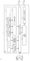
- FIG. 1 is a diagram illustrating a data collection system according to the present disclosure.
- FIG. 2 is a diagram illustrating a terminal of a data collection system according to the present disclosure.
- FIG. 2 is a diagram illustrating a management node of a data collection system according to the present disclosure.
- 1 is a diagram illustrating a frame transmitted from a terminal to a management node.
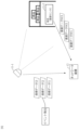
- FIG. 1 shows an example of a plurality of sensor terminals.
- FIG. 1 is a diagram illustrating a data collection system according to the present disclosure.
- the data collection system 301 is a data collection system that performs communication from a terminal 11 to a network device 12 by utilizing an extension area of a standardized communication protocol (such as LLDP, HTIP, IEEE802.11, etc.),
- the terminal 11 stores the sensing data detected by the sensor device in an area of the frame defined by the communication protocol, which is different from the area for storing the metadata, and transmits the data to the network device 12.
- the network device 12 transfers the frame to the management node 13,
- the management node 13 is characterized in that it associates the sensing data with the metadata and stores them based on information for identifying the terminal 11 that is written in the frame.
- the data collection network 15 is a network that connects the terminals 11 that exist within a specific range to the management node 13.
- the data collection network 15 is, for example, a local area network (LAN), a field area network (FAN), an IoT area network, etc.
- LAN local area network
- FAN field area network
- IoT area network IoT area network
- FIG. 2 is a diagram for explaining the terminal 11.
- the terminal 11 is, for example, an IoT sensor terminal that senses an observation target and generates sensing data.
- the terminal 11 has a sensor device 11a, a sensing data storage processing unit 11b, a device information storage processing unit 11c, a communication protocol operation unit 11d1 , metadata detection units ( 11e1 , 11e2 , 11e3 , ...), and a metadata storage processing unit 11f.
- the sensor device 11a senses an object to be observed and acquires sensing data (main data).
- the sensing data may be, for example, temperature, images, acceleration, sound, light, CO2, etc.
- the device information storage processing unit 11c collects device information of the observed target (e.g., the device manufacturer name, model name, model number, etc.) and stores the information in a specified position of the frame (an area that can be used for unique purposes, such as an "extension area” or "optional area” specified by the protocol).
- the sensing data storage processing unit 11b stores the sensing data from the sensor device 11a in a specified position of the frame (such as the payload portion defined by the protocol).
- the sensing data storage processing unit 11b may process the sensing data before storing it in the frame, for example by converting it into a shortened code and storing it, or by splitting it into multiple frames and storing them (fragmentation), so that it conforms to the format/restrictions of the frame's unique extension area.
- the sensing data storage processing unit 11b can arbitrarily set the timing for storing the sensing data in the frame.
- the storage timing can be each time the sensing data is updated, or the sensing data can be stored not sequentially but after it has been accumulated for a certain period of time.
- the sensing data storage processing unit 11b can store a record (log) of the sensing data or the results of specific calculations/statistical processing in the frame.
- the type of sensing data stored in the frame and the storage timing may be fixed or variable.
- the type of sensing data and the storage timing may be dynamically changed by the judgment of the terminal 11 itself or an instruction from the management node 13.
- the frame transmission period may be fixed or variable.
- the frame transmission period may be dynamically changed based on the judgment of the terminal 11 itself or an instruction from the management node 13.
- the metadata detection unit 11e acquires information (metadata) other than device information.
- Information other than device information is, for example, location information of the detection target, time information, person, object, or event information, and other information.
- the present invention does not limit the information other than device information to these.
- the metadata detection unit 11e has a location information detection unit 11e 1 , a time detection unit 11e 2 , a person, object, or event detection unit 11e 3 , and other detection units.
- the location information detection unit 11e 1 is, for example, a GPS, an acceleration sensor, a gyro sensor, or an RSSI receiver for Wi-Fi signals, BLE (Bluetooth Low Energy) beacon signals, etc.
- the location metadata detected by the location information detection unit 11e 1 is information about a location acquired from a GPS signal, a BLE beacon signal, radio wave information of wireless communication, radio wave information of non-communication (television, radio, radio clock, other noise, etc.), power information, visible light information, sound wave information, vibration information, acceleration information, or other location metadata source.
- the time detection unit 11e2 is, for example, an information receiver from GPS or NTP (Network Time Protocol).
- the time metadata detected by the time detection unit 11e2 is information about time acquired from a GPS signal, information from the NTP, or other time metadata sources.
- the person, object, and event detection unit 11e 3 is a receiver that receives, for example, information from a BLE beacon (carried by a person), a smartphone carried by a person, or information from image analysis results.
- the person, object, or event metadata detected by the person, object, and event detection unit 11e 3 is information about a person, object, or event obtained from a BLE beacon carried by a person, information from a smartphone carried by a person, information from image analysis results, or other current event metadata sources.
- Other metadata detected by the detection unit includes information regarding the network configuration of the data collection network 15.
- the metadata detection unit 11e may detect all of the multiple detection targets, or may detect any one of them.
- the metadata storage processing unit 11f stores the data detected by the metadata detection unit 11e as metadata in an extension area or option area in the frame set by the communication protocol.
- the metadata storage processing unit 11f can store metadata in the control system frame of an IEEE 804.11 wireless LAN.
- various metadata are stored in the "Vendor Specific” area, which is an extension area of a Probe Request frame.
- various metadata are stored in the "Vendor Specific” area, which is an extension area of a Probe Response frame.
- the metadata storage processing unit 11f may process the metadata before storing it in the frame, for example by converting it into a shortened code and storing it, or by splitting it and storing it in multiple frames (fragmentation), so that it conforms to the format/restrictions of the frame's unique extension area.
- the metadata storage processing unit 11f can arbitrarily set the timing for storing metadata in a frame.
- the storage timing can be each time the metadata is updated, or the metadata can be stored not sequentially but after it has been accumulated for a certain period of time.
- the metadata storage processing unit 11f can store a record (log) of the metadata or the results of specific calculations/statistical processing in the frame.
- the type of metadata stored in the frame and the storage timing may be fixed or variable.
- the type of metadata and the storage timing may be dynamically changed at the discretion of the terminal 11 itself or in response to an instruction from the management node 13.
- the communication protocol operation unit 11d 1 transmits a frame in which sensing data and device information are stored in a predetermined area and metadata is stored in an extension area or an option area to the network device 12 using a lightweight and standardized communication protocol such as LLDP or HTIP (Home network Topology Identifying Protocol).
- the communication protocol of the frame in which the sensing data is stored and the communication protocol of the frame in which the device information is stored may be the same or different.
- the metadata storage processing unit 11f may store the metadata in a frame of one of the communication protocols (a frame in which the sensing data is stored or a frame in which the device information is stored) or in a frame of both communication protocols (a frame in which the sensing data is stored and a frame in which the device information is stored).
- the terminal 11 also has a function of operating according to instructions from the management node 13, etc. Specifically, the terminal 11 has an instruction interpretation unit 11g, and when the terminal itself changes the BLE beacon signal or metadata information (information to be transmitted, radio wave intensity, transmission frequency, etc.) according to instructions from the management node 13, the terminal transmits the information to the outside.
- the terminal 11 When transmitting information using the same protocol as communication with the network device 12, the terminal 11 operates the communication protocol operation unit 11d1.
- the terminal 11 When transmitting information using a protocol different from that for communication with the network device 12, the terminal 11 has a communication protocol operation unit 11d2 in addition to the communication protocol operation unit 11d1, and operates the communication protocol operation unit 11d2 .
- the terminal 11 itself is a beacon signal source for other terminals to grasp metadata.
- the terminal 11 may be a beacon signal source for identifying location metadata, or a beacon terminal carried by a worker to identify nearby people.
- the network device 12 is, for example, a network switch, a wireless access point, a wireless repeater, etc.
- the network device 12 sends the frames uploaded from the lower data collection network 15 to the management node 13 as is.
- the network device 12 may have a metadata processing unit (metadata detection unit 11e and metadata storage processing unit 11f) that the terminal 11 has. Even if the network device 12 does not have the sensor device 11a, it can add metadata such as its own unique information such as its own MAC address and a connection port to a frame sent from the terminal 11 and transfer the frame to the management node 13. If the network device 12 has a metadata processing section, it becomes possible to grasp the logical connection from the management node 13 to the terminal 11, and a more accurate logical/physical network management map can be created. In other words, even if the network device 12 is a network switch (switching hub) or a wireless repeater that does not have layer 3 or higher functions, this technology operates at layer 2, making it possible to manage and understand the connections between network devices, including the network
- FIG. 3 is a diagram explaining the management node 13.
- the management node 13 has a communication protocol operation unit 13a, an information processing unit 13b, and an information storage unit 13c.
- the management node 13 extracts information from frames passed from the network device 12, stores it, and provides it for analysis.
- the management node 13 is characterized by having the function of storing combinations of two or more pieces of collected information in the information storage unit 13c.
- the communication protocol operation unit 13a receives frames in which sensing data and metadata are stored from the terminal 11 and the network device 12.
- the information processing unit 12b extracts the following sensing data, device information, and metadata from the received frames, and organizes them in the information storage unit 13c based on information that identifies the individual terminal 11 (e.g., MAC address).
- the management node 13 refers to metadata related to a location and stores the main data acquired at the same location or within a certain area in the format of [location metadata, main data]. [supplement] Further details on location metadata. Like GPS information, there are cases where the information has become direct location metadata at the time of sensing by the terminal 11.
- FIG. 4 is a diagram explaining a frame 41 transmitted from the terminal 11 to the management node 13.
- the network device 12 is not shown in FIG. 4.
- the frame 41 is a layer 2 communication frame such as an Ethernet (registered trademark) frame or a Wi-Fi communication frame.
- the frame 41 is composed of a logical identifier 41a of the communication device such as a MAC address, a source and destination identifier 41b such as an IP address, an area 41c in which sensing data such as temperature and images are stored, and an extension area 41d in which metadata is stored.
- the identifier 41b and area 41c form a layer 3 communication packet.
- the management node 13 for example, links the MAC address of the logical identifier 41a with the location metadata of the extension area 41d to [MAC address, location metadata], and links the MAC address of the logical identifier 41a with the installer metadata of the extension area 41d to [MAC address, installer metadata], and organizes them in the information storage unit 13c.
- the data collection system 301 can acquire network configuration information, device information, sensing data, and metadata of terminals and devices using a communication protocol that does not require high performance.
- the sensor terminal 11-1 is a sensor terminal in which the sensor device 11a is a camera and transmits image data as sensing data.
- the sensor terminal 11-2 is a sensor terminal in which the sensor device 11a is a weight sensor and transmits weight data as sensing data.
- the sensor terminal 11-2 is installed on a product shelf and detects the load on the product shelf applied by the products placed on it.
- image data I1, I2, and I3 captured by sensor terminal 11-1 are used to detect the event of "a customer picking up a product on a shelf/putting it in a basket," and when this event is detected, the "product on the shelf” is identified using the change in weight data W1, W2, and W3 detected by sensor terminal 11-2.
- the sensing data at the time of this event is matched based on the timestamp attached to the sensing data.
- this timestamp is provided by a network device 12, such as an IoT-GW, that is placed in the data collection network 15. Therefore, if a delay, loss, or change in order occurs in the local network from the sensor terminal 11 to the network device 12, an error will occur in determining the order of the sensing data. Therefore, if a delay or loss occurs in the sensing data midway through the network, it becomes difficult to match the sensing data between different sensor terminals.
- a network device 12 such as an IoT-GW
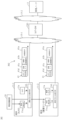
- FIG. 6 shows an example of a data collection system equipped with multiple sensor terminals.
- the data collection system of this embodiment includes sensor terminals 11-1 and 11-2, and a time information source 16 that functions as a time series information source.
- the time information source 16 broadcasts a time signal that includes time information.
- the time signal is a signal that can be received as metadata by the sensor terminals 11-1 and 11-2, and can be, for example, a beacon signal that only reaches the sensor terminals 11-1 and 11-2 that are located in close proximity.
- the time signal can be any signal broadcast within the same space, and can be a beacon signal that contains time information, or a GPS signal that also contains time information.
- the sensor terminals 11-1 and 11-2 each include a time receiving unit 11e4 that receives a time signal from a time information source 16.
- the time receiving unit 11e4 can use the metadata detecting unit described in the first embodiment.
- the sensor terminals 11-1 and 11-2 store the time information received by the time receiving unit 11e4 in the extension area 41d of the layer 2 communication protocol and transmit the stored information. This transmission can be performed, for example, by using the metadata storage processing unit 11f and the communication protocol operation unit 11d1 described in FIG. 2.
- the management node 13 receives the frame 41 and uses the time information stored in the extension area 41d to determine the order of the sensing data stored in the area 41c.
- the management node 13 compares the sensing data sent from the sensor terminals 11-1 and 11-2, and controls devices such as register devices that are different from the sensor terminals 11-1 and 11-2 based on the result of the comparison.
- the time information stored in the extension area 41d is time information from a common time information source 16 stored in the sensor terminals 11-1 and 11-2. Therefore, this embodiment is not affected by packet delays, losses, or reordering within the local network, improving the accuracy of matching for the same event.
- the metadata stored in the extension area 41d of the frame 41 may be transferred from the extension area 41d to the same area 41c as the main data by a protocol processing unit such as the IoT-GW 12G.
- the management node 13 uses the time information stored in the area 41c to determine the order of the sensing data.
- time stamps with high accuracy can be assigned to the time-series weight data W1 to W3 from the sensor terminal 11-2, which is a weight sensor, and the image data I1 to I3 from the camera, making it easy to identify them as belonging to the same event (e.g., "Customer A picks up an item on shelf B"). Therefore, in unmanned stores, etc., it is possible to accurately extract which user picked up which item from the weight changes in the shelf's weight sensor and image data from the surveillance camera.
- multiple sensor terminals 11-1 and 11-2 may acquire time information from different time information sources 16 that are time-synchronized.
- the time information may be any time series information that can identify a time series, such as an event identification symbol or a serial number.
- the different sensor terminals 11 are sensor terminals 11-1 and 11-2 with different sensor types, but the present disclosure is not limited to this.
- the different sensor terminals 11 may be sensor terminals 11 with the same sensor type.
- the present disclosure can accurately acquire the time series and timing of sensing data detected by multiple sensor terminals 11-1 and 11-2. Therefore, by collecting metadata on the location and status (moving, stopped, strong impact, sound, etc.) of workers in the work space (office, warehouse, etc.) in real time and using this as an event occurrence flag (an identifier for identifying the event) for multiple nearby sensors, the searchability of large amounts of accumulated data is improved.
- the above-mentioned sensor terminal 11 and management node 13 can also be realized by a computer and a program, and the program can be recorded on a recording medium or provided via a network.
Landscapes
- Engineering & Computer Science (AREA)
- Computer Networks & Wireless Communication (AREA)
- Signal Processing (AREA)
- Computer Security & Cryptography (AREA)
- Arrangements For Transmission Of Measured Signals (AREA)
Abstract
本開示は、ネットワークの途中でデータに遅延や欠損が発生する環境においても、センシングデータの突合を可能にすることを目的とする。 本開示は、複数のセンサ端末で取得されたセンシングデータを管理ノードに収集するデータ収集システムであって、時系列を識別可能な時系列情報を配信する時系列情報源を備え、前記複数のセンサ端末は、前記時系列情報源からの前記時系列情報を、レイヤ2の通信プロトコルの拡張領域を利用して送信することを特徴とするデータ収集システムである。
Description
本開示は、IoT(Internet of Things)におけるセンシングデータ収集に関する。
標準規格化されており、かつ、高い性能を要求しない軽量の通信プロトコルで、端末や機器のネットワーク構成情報や機器情報を取得する。例えば、非特許文献1では、LLDP(Link Layer Discovery Protocol、例えば非特許文献3を参照。)を用いた方法が報告されている。
IoTにおいては、数多くのセンサー端末をネットワーク接続し、それらが生成するデータ(センシングデータ)を収集する必要がある。また、IoTにおけるデータ活用においては、センサー端末が生成するセンシングデータそのものだけではなく、メタデータと呼ばれる、センシングデータに関するデータの重要性が報告されており(非特許文献2など)、センシングデータとメタデータを合わせて取得且つ流通させることで、利用者がセンシングデータを安全かつ容易に活用することが期待されている。例えば、非特許文献1に開示されるLLDPを利用すれば、経済的なシステム構成で、センシングデータに関するメーカ名や型番などのメタデータ(機器情報)を収集できる。
複数のセンサー端末を用いることで、店舗内の店員を無人化した無人店舗又は無人レジシステムが可能になる。このような無人店舗又は無人レジシステムでは、「顧客が棚の製品を手に取った・カゴに入れた」という出来事を確実に把握する為、カメラや商品棚に仕込んだ重量センサ等の両面から情報を突合し、顧客が購入しようとしている製品を特定する。画像データや重量データ等のセンシングデータの突合は、センシングデータに付与されるタイムスタンプに基づいて行われる。
しかし、このタイムスタンプは、データ収集ネットワークに配置されているIoT-GWなどのネットワーク装置によって付与される。このため、センサ端末からネットワーク装置までのローカルネットワークにおいて遅延、欠損又は順序の入れ替わりが発生した場合、センシングデータの順序の判定に誤りが生じることになる。このため、ネットワークの途中でセンシングデータに遅延や欠損が発生した場合、異なるセンサ端末間でのセンシングデータの突合が困難になる。
美原 義行、山崎 毅文、岡本 学、佐藤 敦、「ホームネットワークマップ特定プロトコルHTIPの設計と診断ツールへの適用」、情報処理学会論文誌 コンシューマ・デバイス&システム、Vol.2、 No.3、 pp.34-45、Dec. 2012.
小田 利彦、今井 紘、内藤 丈嗣、竹林 一、「センシングデータ流通市場におけるメタデータの定義・生成・活用の一方式」、2018年度人工知能学会全国大会(第32回)、June 2012.
IEEE Std 802.1AB-2016, "IEEE Standard for Local and metropolitan area networks-Station and Media Access Control Connectivity Discovery"
IEEE Std 802.11TM-2016 P.708(Probe Reqest)、P.712(Probe Response)
本開示は、ネットワークの途中でセンシングデータに遅延や欠損が発生する環境においても、センシングデータの突合を可能にすることを目的とする。
本開示のデータ収集システムは、複数のセンサ端末で取得されたセンシングデータを管理ノードに収集するデータ収集システムであって、時系列を識別可能な時系列情報を配信する時系列情報源を備える。本開示のセンサ端末及び管理ノードは、本開示のデータ収集方法を実行する。
具体的には、前記センサ端末は、時系列を識別可能な時系列情報を配信する時系列情報源からの前記時系列情報を、レイヤ2の通信プロトコルの拡張領域を利用して送信する。
具体的には、前記管理ノードは、時系列を識別可能な時系列情報を、レイヤ2の通信プロトコルの拡張領域を利用して前記センサ端末から受信し、受信した前記時系列情報を用いて、前記複数のセンサ端末から送信されたセンシングデータの順序を判定する。
前記複数のセンサ端末は、レイヤ3の通信プロトコルの領域を利用してセンシングデータを送信してもよい。この場合、前記管理ノードは、前記拡張領域に格納されている時系列情報を用いて、前記複数のセンサ端末から送信されたセンシングデータの順序を判定してもよい。
本開示のデータ収集システムは、前記センシングデータを転送するネットワーク装置を備え、前記ネットワーク装置において、前記拡張領域に格納されている時系列情報を、前記センシングデータの格納領域に移動させてもよい。この場合、前記管理ノードは、レイヤ3の通信プロトコルの領域に格納されている時系列情報を用いて、前記複数のセンサ端末から送信されたセンシングデータの順序を判定してもよい。
前記管理ノードは、前記複数のセンサ端末から送信されたセンシングデータを突合し、突合の結果に基づいて、前記複数のセンサ端末とは異なる装置の制御を行ってもよい。
前記時系列情報源は、時刻情報を含む時刻信号を送信するビーコンであってもよい。
なお、上記各発明は、可能な限り組み合わせることができる。
本開示は、ネットワークの途中でデータに遅延や欠損が発生する環境においても、センシングデータの突合を可能にすることができる。
添付の図面を参照して本発明の実施形態を説明する。以下に説明する実施形態は本発明の実施例であり、本発明は、以下の実施形態に制限されるものではない。なお、本明細書及び図面において符号が同じ構成要素は、相互に同一のものを示すものとする。
(実施形態1)
本実施形態では、データ収集システムの基本構成を説明する。
図1は、本実施形態のデータ収集システム301を説明する図である。データ収集システム301は、端末11からネットワーク装置12への通信を標準規格化された通信プロトコル(LLDPやHTIP、IEEE802.11、等)の拡張領域を活用して行うデータ収集システムであって、
端末11は、センサーデバイスが検出したセンシングデータを、前記通信プロトコルで規定されるフレーム内の、メタデータを格納する領域とは異なる領域に格納し、ネットワーク装置12へ送出し、
ネットワーク装置12は、前記フレームを管理ノード13へ転送し、
管理ノード13は、前記フレームに記載される端末11を識別する情報に基づいて、前記センシングデータと前記メタデータとを関連付けて保管する
ことを特徴とする。
本実施形態では、データ収集システムの基本構成を説明する。
図1は、本実施形態のデータ収集システム301を説明する図である。データ収集システム301は、端末11からネットワーク装置12への通信を標準規格化された通信プロトコル(LLDPやHTIP、IEEE802.11、等)の拡張領域を活用して行うデータ収集システムであって、
端末11は、センサーデバイスが検出したセンシングデータを、前記通信プロトコルで規定されるフレーム内の、メタデータを格納する領域とは異なる領域に格納し、ネットワーク装置12へ送出し、
ネットワーク装置12は、前記フレームを管理ノード13へ転送し、
管理ノード13は、前記フレームに記載される端末11を識別する情報に基づいて、前記センシングデータと前記メタデータとを関連付けて保管する
ことを特徴とする。
データ収集ネットワーク15は、特定の範囲に存在する端末11と管理ノード13とを接続するネットワークである。データ収集ネットワーク15は、例えば、ローカルエリアネットワーク(LAN)、フィールドエリアネットワーク(FAN)、IoTエリアネットワークなどである。同じデータ収集ネットワーク15内に、単一種類の端末11が複数存在する場合と、複数種類の端末11が存在する場合がある。
図2は、端末11を説明する図である。
端末11は、例えば、IoTセンサ端末であり、観測対象に関するセンシングを行い、センシングデータを生成する。端末11は、センサーデバイス11a、センシングデータ格納処理部11b、機器情報格納処理部11c、通信プロトコル動作部11d1、メタデータ検出部(11e1、11e2、11e3、・・・)、及びメタデータ格納処理部11fを有する。
端末11は、例えば、IoTセンサ端末であり、観測対象に関するセンシングを行い、センシングデータを生成する。端末11は、センサーデバイス11a、センシングデータ格納処理部11b、機器情報格納処理部11c、通信プロトコル動作部11d1、メタデータ検出部(11e1、11e2、11e3、・・・)、及びメタデータ格納処理部11fを有する。
センサーデバイス11aは、観測対象に関するセンシングを行い、センシングデータ(主データ)を取得する。センシングデータは、例えば、温度、画像、加速度、音、光、CO2等である。
機器情報格納処理部11cは、観測対象の機器情報(例えば、機器のメーカ名、機種名、型番等)を収集し、フレームの所定位置(プロトコルで規定される“拡張領域”や“オプション領域”等の独自用途で使用可能な領域)に当該情報を格納する。
機器情報格納処理部11cは、観測対象の機器情報(例えば、機器のメーカ名、機種名、型番等)を収集し、フレームの所定位置(プロトコルで規定される“拡張領域”や“オプション領域”等の独自用途で使用可能な領域)に当該情報を格納する。
センシングデータ格納処理部11bは、センサーデバイス11aからのセンシングデータをフレームの所定位置(プロトコルで規定されるペイロード部分など)に格納する。センシングデータ格納処理部11bは、フレームの独自拡張領域の様式/制限に適合するように、センシングデータを、ある短縮コードに変換して格納したり、分割して複数フレームに分けて格納(フラグメンテーション)するなど、加工した後にフレームに格納してもよい。
センシングデータ格納処理部11bは、センシングデータをフレームに格納する格納タイミングを任意に設定することができる。例えば、当該格納タイミングをセンシングデータ更新の都度とすることもできるし、センシングデータを逐次格納ではなく一定期間蓄積したタイミングで格納してもよい。また、センシングデータ格納処理部11bは、センシングデータを一定期間蓄積した場合、その記録(ログ)や、特定の計算/統計処理をした結果をフレームに格納してもよい。
フレームに格納するセンシングデータの種別や格納タイミングは固定されていても変動してもよい。端末11自身の判断、管理ノード13からの指示でセンシングデータの種別や格納タイミングを動的に変更してもよい。
また、フレームの送信周期も固定されていてもよいし変動してもよい。端末11自身の判断、管理ノード13からの指示でフレームの送信周期を動的に変更してもよい。
また、フレームの送信周期も固定されていてもよいし変動してもよい。端末11自身の判断、管理ノード13からの指示でフレームの送信周期を動的に変更してもよい。
メタデータ検出部11eは、機器情報以外の情報(メタデータ)を取得する。機器情報以外の情報とは、例えば、検出対象の位置情報、時刻情報、人、モノ、又は出来事情報、及びその他情報である。ただし、本発明は機器情報以外の情報をこれらに限定しない。メタデータ検出部11eは、これらの情報を取得するために、位置情報検出部11e1、時刻検出部11e2、人、モノ、出来事検出部11e3、及びその他の検出部を有する。
位置情報検出部11e1は、例えば、GPS、加速度センサ、ジャイロセンサ、あるいはWi-Fi信号やBLE(Bluetooth Low Energy)ビーコン信号などのRSSI受信器である。そして、位置情報検出部11e1が検出する場所メタデータは、GPS信号、BLEビーコン信号、無線通信の電波情報、非通信の電波情報(テレビ、ラジオ、電波時計、その他ノイズ等)、電力情報、可視光情報、音波情報、振動情報、加速度情報、その他の場所メタデータ源から取得した位置に関する情報である。
時刻検出部11e2は、例えば、GPS、NTP(Network Time Protocol)からの情報受信器である。そして、時刻検出部11e2が検出する時刻メタデータは、GPS信号、NTPからの情報、その他の時刻メタデータ源から取得した時刻に関する情報である。
人、モノ、出来事検出部11e3は、例えば、BLEビーコン(人に所持させる)、人が所持しているスマートフォンからの情報や画像解析結果からの情報を受信する受信器である。人、モノ、出来事検出部11e3が検出する人、モノ、又は出来事メタデータは、人に所持させたBLEビーコン、人が所持しているスマートフォンからの情報、画像解析結果からの情報、その他の時事メタデータ源から取得した人、モノ、又は出来事に関する情報である。
その他の検出部が検出するメタデータとしては、データ収集ネットワーク15のネットワーク構成に関する情報などがある。
なお、メタデータ検出部11eは、複数の検出対象のうち全てを検出してもよいし、任意の1つを検出してもよい。
メタデータ格納処理部11fは、メタデータ検出部11eが検出したデータをメタデータとして通信プロトコルで設定されているフレーム内の拡張領域又はオプション領域に格納する。例えば、メタデータ格納処理部11fは、IEEE804.11無線LANの制御系フレームにメタデータを格納することができる。具体的には、Probe Request(プローブ要求)フレームの拡張領域である“Vendor Specific”領域に、各種メタデータを格納する。あるいは、Probe Response(プローブ応答)フレームの拡張領域である“Vendor Specific”領域に、各種メタデータを格納する。
メタデータ格納処理部11fは、フレームの独自拡張領域の様式/制限に適合するように、メタデータを、ある短縮コードに変換して格納したり、分割して複数フレームに分けて格納(フラグメンテーション)するなど、加工した後にフレームに格納してもよい。
メタデータ格納処理部11fは、メタデータをフレームに格納する格納タイミングを任意に設定することができる。例えば、当該格納タイミングをメタデータ更新の都度とすることもできるし、メタデータを逐次格納ではなく一定期間蓄積したタイミングで格納してもよい。また、メタデータ格納処理部11fは、メタデータを一定期間蓄積した場合、その記録(ログ)や、特定の計算/統計処理をした結果をフレームに格納してもよい。
フレームに格納するメタデータの種別や格納タイミングは固定されていても変動してもよい。端末11自身の判断、管理ノード13からの指示でメタデータの種別や格納タイミングを動的に変更してもよい。
通信プロトコル動作部11d1は、所定領域にセンシングデータや機器情報が格納され、拡張領域又はオプション領域にメタデータが格納されたフレームを、例えば、LLDPもしくはHTIP(Home network Topology Identifying Protocol)のような軽量で標準規格化された通信プロトコルを用いてネットワーク装置12へ送信する。なお、センシングデータが格納されたフレームの通信プロトコルと、機器情報が格納されたフレームの通信プロトコルとは、同一であっても異なっていてもよい。後者の場合、メタデータ格納処理部11fは、メタデータをいずれか1つの通信プロトコルのフレーム(センシングデータが格納されたフレーム又は機器情報が格納されたフレーム)に格納してもよいし、両方の通信プロトコルのフレーム(センシングデータが格納されたフレーム及び機器情報が格納されたフレーム)に格納してもよい。
さらに、端末11は、管理ノード13等からの指示に従って動作する機能も持つ。具体的には、端末11は、指示解釈部11gを有し、管理ノード13からの指示に従って、端末自身が発信するBLEビーコン信号やメタデータ情報(発信する情報、電波強度、送出頻度等)を変化させる場合、その情報を外部に情報発信する。ネットワーク装置12との通信と同じプロトコルで情報発信する場合、通信プロトコル動作部11d1を動作させる。ネットワーク装置12との通信と異なるプロトコルで情報発信する場合、通信プロトコル動作部11d1の他に通信プロトコル動作部11d2を備え、通信プロトコル動作部11d2を動作させる。
なお、端末11自体が、他の端末がメタデータを把握する為のビーコン信号源である場合も含む。例えば、端末11は、場所メタデータを識別する為のビーコン信号源であってもよいし、近接した人を識別する為に作業者に所持させるビーコン端末であってもよい。
ネットワーク装置12は、例えば、ネットワークスイッチ、無線アクセスポイント、無線リピータ等の装置である。ネットワーク装置12は、下位のデータ収集ネットワーク15からアップロードされたフレーム群をそのまま管理ノード13へ送出する。
ここで、ネットワーク装置12は、端末11が有するメタデータの処理部分(メタデータ検出部11e及びメタデータ格納処理部11f)を有していてもよい。ネットワーク装置12は、センサデバイス11aを持たない場合も、端末11から送られてきたフレームに、自身のMACアドレス等の固有情報、接続ポート等のメタデータを追加で付与し、管理ノード13へ転送することができる。
ネットワーク装置12がメタデータの処理部分を有せば、管理ノード13から端末11までの論理的なつながりを把握可能となり、より正確な論理的/物理的なネットワーク管理マップを作成することができる。
つまり、ネットワーク装置12がレイヤ3以上の機能を持たないネットワークスイッチ(スイッチングハブ)や無線リピータ等であっても、本技術はレイヤ2で行うため、ネットワーク装置12も含めたネットワーク機器のつながりを管理/把握できるようになる。
ここで、ネットワーク装置12は、端末11が有するメタデータの処理部分(メタデータ検出部11e及びメタデータ格納処理部11f)を有していてもよい。ネットワーク装置12は、センサデバイス11aを持たない場合も、端末11から送られてきたフレームに、自身のMACアドレス等の固有情報、接続ポート等のメタデータを追加で付与し、管理ノード13へ転送することができる。
ネットワーク装置12がメタデータの処理部分を有せば、管理ノード13から端末11までの論理的なつながりを把握可能となり、より正確な論理的/物理的なネットワーク管理マップを作成することができる。
つまり、ネットワーク装置12がレイヤ3以上の機能を持たないネットワークスイッチ(スイッチングハブ)や無線リピータ等であっても、本技術はレイヤ2で行うため、ネットワーク装置12も含めたネットワーク機器のつながりを管理/把握できるようになる。
図3は、管理ノード13を説明する図である。管理ノード13は、通信プロトコル動作部13a、情報処理部13b及び情報格納部13cを有する。管理ノード13は、ネットワーク装置12から渡されたフレームから情報を取り出して保管し、分析に供する。特に、管理ノード13は、収集した2以上の情報の組み合わせを情報格納部13cに格納する機能を持つことが特徴である。
通信プロトコル動作部13aは、端末11やネットワーク装置12からのセンシングデータやメタデータが格納されたフレームを受信する。情報処理部12bは、受信したフレームから以下のようなセンシングデータ、機器情報、及びメタデータを取り出し、これらを端末11の個体を識別する情報(例:MACアドレス)を基に情報格納部13cに整理する。
(1)端末の物理的な情報(筐体の特長、画像情報、貼られたラベルの情報、作業者が指をさしている対象、作業者の視線の対象、等の情報)
(2)論理ネットワーク上の端末の識別子(MACアドレス、UUID等)
(3)主データ(温度、画像、加速度、音、光、CO2等のセンシングデータ)
(4)各種メタデータ(場所、時刻、人、モノ、出来事等のデータ)
例えば、管理ノード13は、場所に関するメタデータを参照し、同一場所あるいはある領域内で取得された主データを[場所メタデータ、主データ]という形式で保管する。
[補足]
場所メタデータについて補足する。
GPS情報のように、端末11でセンシングされた時点で直接的な場所メタデータとなっている場合もある。一方、BLEビーコンからの信号、可視光、あるいは音情報のように、端末11でセンシングされてメタデータとして送出される時点では場所情報かどうかは確定されておらず、管理ノード13が当該メタデータを場所メタデータとして認識/把握する場合もある。
[補足終了]
(1)端末の物理的な情報(筐体の特長、画像情報、貼られたラベルの情報、作業者が指をさしている対象、作業者の視線の対象、等の情報)
(2)論理ネットワーク上の端末の識別子(MACアドレス、UUID等)
(3)主データ(温度、画像、加速度、音、光、CO2等のセンシングデータ)
(4)各種メタデータ(場所、時刻、人、モノ、出来事等のデータ)
例えば、管理ノード13は、場所に関するメタデータを参照し、同一場所あるいはある領域内で取得された主データを[場所メタデータ、主データ]という形式で保管する。
[補足]
場所メタデータについて補足する。
GPS情報のように、端末11でセンシングされた時点で直接的な場所メタデータとなっている場合もある。一方、BLEビーコンからの信号、可視光、あるいは音情報のように、端末11でセンシングされてメタデータとして送出される時点では場所情報かどうかは確定されておらず、管理ノード13が当該メタデータを場所メタデータとして認識/把握する場合もある。
[補足終了]
図4は、端末11から管理ノード13へ送信されるフレーム41を説明する図である。図4では、ネットワーク装置12の記載を省略している。フレーム41は、イーサネット(登録商標)フレームやWi-Fi通信フレームのようなレイヤ2通信フレームである。フレーム41は、MACアドレス等の通信デバイスの論理識別子41a、IPアドレスのような送信元や宛先の識別子41b、温度や画像などのセンシングデータが格納される領域41c、及びメタデータが格納される拡張領域41dで構成される。このうち、識別子41bと領域41cがレイヤ3通信パケットとなる。
管理ノード13は、例えば、論理識別子41aのMACアドレスと拡張領域41dの場所メタデータを組み合わせて[MACアドレス、場所メタデータ]、論理識別子41aのMACアドレスと拡張領域41dの設置者メタデータを組み合わせて[MACアドレス、設置者メタデータ]のように紐づけて情報格納部13cに整理する。
このように、データ収集システム301は、高い性能を要求しない通信プロトコルで、端末や機器のネットワーク構成情報、機器情報、センシングデータ及びメタデータを取得することができる。
(実施形態2)
図5は、センサ端末が使用される態様の一例を示す。センサ端末11-1は、センサーデバイス11aがカメラであり、センシングデータとして画像データを送信するセンサ端末である。センサ端末11-2は、センサーデバイス11aが重量センサであり、センシングデータとして重量データを送信するセンサ端末である。センサ端末11-2は、商品棚に設置され、載せられている商品によって加わる商品棚への荷重を検出する。
図5は、センサ端末が使用される態様の一例を示す。センサ端末11-1は、センサーデバイス11aがカメラであり、センシングデータとして画像データを送信するセンサ端末である。センサ端末11-2は、センサーデバイス11aが重量センサであり、センシングデータとして重量データを送信するセンサ端末である。センサ端末11-2は、商品棚に設置され、載せられている商品によって加わる商品棚への荷重を検出する。
無人店舗/無人レジシステムでは、センサ端末11-1で撮影された画像データI1、I2、I3を用いて「顧客が棚の製品を手に取った・カゴに入れた」というイベントを検出し、このイベントが検出されたときにセンサ端末11-2で検出された重量データW1、W2、W3の変化を用いて「棚の製品」を特定する。このイベント発生時のセンシングデータの突合は、センシングデータに付与されるタイムスタンプに基づいて行われる。
しかし、このタイムスタンプは、データ収集ネットワーク15に配置されているIoT-GWなどのネットワーク装置12によって付与される。このため、センサ端末11からネットワーク装置12までのローカルネットワークにおいて遅延、欠損又は順序の入れ替わりが発生した場合、センシングデータの順序の判定に誤りが生じることになる。このため、ネットワークの途中でセンシングデータに遅延や欠損が発生した場合、異なるセンサ端末間でのセンシングデータの突合が困難になる。
図6は、複数のセンサ端末の備わるデータ収集システムの一例を示す。本実施形態のデータ収集システムは、センサ端末11-1及び11-2と、時系列情報源として機能する時刻情報源16と、を備える。時刻情報源16は、時刻情報を含む時刻信号をブロードキャストする。時刻信号は、センサ端末11-1及び11-2がメタデータとして受信可能な信号であり、例えば近接した位置に配置されているセンサ端末11-1及び11-2のみに届くビーコン信号を用いることができる。
時刻信号は、同一空間内にブロードキャストされる任意の信号を用いることが可能であり、時刻情報を含むビーコン信号のほか、時刻情報が含まれているGPS信号等も用いることができる。
センサ端末11-1及び11-2は、時刻情報源16からの時刻信号を受信する時刻受信部11e4を備える。時刻受信部11e4は、実施形態1で説明したメタデータ検出部を用いることができる。センサ端末11-1及び11-2は、時刻受信部11e4において受信された時刻情報を、レイヤ2の通信プロトコルの拡張領域41dに格納して送信する。この送信は、例えば、図2で説明したメタデータ格納処置部11f及び通信プロトコル動作部11d1を用いて行うことができる。
センサ端末11-1から送信されるフレーム41は、領域41cにセンシングデータである画像データが格納され、拡張領域41dに時刻情報が格納される。センサ端末11-2から送信されるフレーム41は、領域41cにセンシングデータである重量データが格納され、拡張領域41dに時刻情報が格納される。
管理ノード13は、フレーム41を受信し、拡張領域41dに格納されている時刻情報を用いて、領域41cに格納されているセンシングデータの順序を判定する。管理ノード13は、センサ端末11-1及び11-2から送信されたセンシングデータを突合し、突合の結果に基づいて、センサ端末11-1及び11-2とは異なるレジスタ装置などの装置の制御を行う。
拡張領域41dに格納されている時刻情報は、センサ端末11-1及び11-2において格納された、共通の時刻情報源16からの時刻情報である。このため、本実施形態は、ローカルネットワーク内のパケット遅延・欠損・順序入れ替わりの影響を受けないので、同一出来事としての突合の正確性が向上する。
なお、フレーム41の拡張領域41dに格納されているメタデータは、IoT-GW12G等のプロトコル処理部によって、拡張領域41dから主データと同じ領域41cに載せ替えられてもよい。この場合、管理ノード13は、領域41cに格納されている時刻情報を用いて、センシングデータの順序を判定する。
本実施形態は、重量センサであるセンサ端末11-2からの時系列の重量データW1~W3と、カメラからの画像データI1~I3と、それぞれに対して、同一出来事(「顧客Aが棚Bの商品を手に取った」等)として判別することを容易にするような精度の高いタイムスタンプを付与できる。このため、無人店舗等において、棚の重量センサの重量変化と監視カメラの画像データから、どのユーザが何の商品を手にとったかを正確に抽出することができる。
なお、複数のセンサ端末11-1及び11-2が同一空間に配置され、共通の時刻情報源16から時刻情報を取得する例を示したが、本開示はこれに限定されない。例えば、複数のセンサ端末11-1及び11-2は、時刻同期されている異なる時刻情報源16から時刻情報を取得してもよい。また、時刻情報は、イベントの識別記号、シリアル番号等の、時系列を識別可能な任意の時系列情報であってもよい。
また、本実施形態では異なるセンサ端末11がセンサ種類の異なるセンサ端末11-1及び11-2である例を示したが、本開示はこれに限定されない。例えば、異なるセンサ端末11はセンサ種類の同じセンサ端末11であってもよい。
本開示は、複数のセンサ端末11-1及び11-2で検出されたセンシングデータの時系列やタイミングを正確に取得することができる。このため、作業空間(オフィス、倉庫、等)における作業者の位置・状態(移動中、停止中、強い衝撃、音、etc…)メタデータをリアルタイムに収集し、それらを付近の複数センサにおけるイベント発生フラグ(該イベントを識別するための識別子)として利用することにより、大量に蓄積されたデータの検索性が向上する。
(他の実施形態)
上述したセンサー端末11及び管理ノード13は、コンピュータとプログラムによっても実現でき、プログラムを記録媒体に記録することも、ネットワークを通して提供することも可能である。
上述したセンサー端末11及び管理ノード13は、コンピュータとプログラムによっても実現でき、プログラムを記録媒体に記録することも、ネットワークを通して提供することも可能である。
11:端末
11-1、11-2:センサ端末
11a:センサーデバイス
11b:センシングデータ格納処理部
11c:機器情報格納処理部
11d1、11d2:通信プロトコル動作部
11e、11e1、11e2、11e3、・・・:メタデータ検出部
11f:メタデータ格納処理部
11g:指示解釈部
12:ネットワーク装置
12G:IoT-GW
13:管理ノード
13a:通信プロトコル動作部
13b:情報処理部
13c:情報格納部
15、15-1、15-2:データ収集ネットワーク
41:フレーム
41a:論理識別子
41b:送信元/宛先識別子
41c:主データ領域
41d:拡張領域
301~302:データ収集システム
11-1、11-2:センサ端末
11a:センサーデバイス
11b:センシングデータ格納処理部
11c:機器情報格納処理部
11d1、11d2:通信プロトコル動作部
11e、11e1、11e2、11e3、・・・:メタデータ検出部
11f:メタデータ格納処理部
11g:指示解釈部
12:ネットワーク装置
12G:IoT-GW
13:管理ノード
13a:通信プロトコル動作部
13b:情報処理部
13c:情報格納部
15、15-1、15-2:データ収集ネットワーク
41:フレーム
41a:論理識別子
41b:送信元/宛先識別子
41c:主データ領域
41d:拡張領域
301~302:データ収集システム
Claims (8)
- 複数のセンサ端末で取得されたセンシングデータを管理ノードに収集するデータ収集システムに備わる前記センサ端末であって、
時系列を識別可能な時系列情報を配信する時系列情報源からの前記時系列情報を、レイヤ2の通信プロトコルの拡張領域を利用して送信する
ことを特徴とするセンサ端末。 - レイヤ3の通信プロトコルの領域を利用してセンシングデータを送信することを特徴とする請求項1に記載のセンサ端末。
- 前記時系列情報源は、時刻情報を含む時刻信号を送信するビーコンであることを特徴とする請求項1に記載のセンサ端末。
- 複数のセンサ端末で取得されたセンシングデータを管理ノードに収集するデータ収集システムに備わる前記管理ノードであって、
前記管理ノードは、時系列を識別可能な時系列情報を、レイヤ2の通信プロトコルの拡張領域を利用して前記センサ端末から受信し、
受信した前記時系列情報を用いて、前記複数のセンサ端末から送信されたセンシングデータの順序を判定する
管理ノード。 - 前記複数のセンサ端末から送信されたセンシングデータを突合し、突合の結果に基づいて、前記複数のセンサ端末とは異なる装置の制御を行うことを特徴とする請求項4に記載の管理ノード。
- 時系列を識別可能な時系列情報を配信する時系列情報源と、
前記時系列情報源からの前記時系列情報を取得する、請求項1から3のいずれかに記載のセンサ端末と、
請求項4又は5に記載の管理ノードと、
を備えるデータ収集システム。 - 複数のセンサ端末で取得されたセンシングデータを管理ノードに収集するデータ収集システムに備わる前記センサ端末が実行する方法であって、
前記センサ端末は、時系列を識別可能な時系列情報を配信する時刻情報源からの前記時系列情報を、レイヤ2の通信プロトコルの拡張領域を利用して送信する
方法。 - 複数のセンサ端末で取得されたセンシングデータを管理ノードに収集するデータ収集システムに備わる前記管理ノードが実行する方法であって、
前記管理ノードは、時系列を識別可能な時系列情報を、レイヤ2の通信プロトコルの拡張領域を利用して前記センサ端末から受信し、
受信した前記時系列情報を用いて、前記複数のセンサ端末から送信されたセンシングデータの順序を判定する
方法。
Priority Applications (2)
| Application Number | Priority Date | Filing Date | Title |
|---|---|---|---|
| PCT/JP2022/045226 WO2024122017A1 (ja) | 2022-12-08 | 2022-12-08 | データ収集システム |
| JP2024562513A JPWO2024122017A1 (ja) | 2022-12-08 | 2022-12-08 |
Applications Claiming Priority (1)
| Application Number | Priority Date | Filing Date | Title |
|---|---|---|---|
| PCT/JP2022/045226 WO2024122017A1 (ja) | 2022-12-08 | 2022-12-08 | データ収集システム |
Publications (1)
| Publication Number | Publication Date |
|---|---|
| WO2024122017A1 true WO2024122017A1 (ja) | 2024-06-13 |
Family
ID=91379041
Family Applications (1)
| Application Number | Title | Priority Date | Filing Date |
|---|---|---|---|
| PCT/JP2022/045226 Ceased WO2024122017A1 (ja) | 2022-12-08 | 2022-12-08 | データ収集システム |
Country Status (2)
| Country | Link |
|---|---|
| JP (1) | JPWO2024122017A1 (ja) |
| WO (1) | WO2024122017A1 (ja) |
Citations (2)
| Publication number | Priority date | Publication date | Assignee | Title |
|---|---|---|---|---|
| US20110216658A1 (en) * | 2010-03-02 | 2011-09-08 | Raul Hernan Etkin | Synchronization in a wireless node |
| JP2021012518A (ja) * | 2019-07-05 | 2021-02-04 | クラスメソッド株式会社 | 無人店舗の商品を管理する管理サーバ及び管理方法 |
Family Cites Families (3)
| Publication number | Priority date | Publication date | Assignee | Title |
|---|---|---|---|---|
| JP4837389B2 (ja) * | 2006-01-31 | 2011-12-14 | 鹿島建設株式会社 | 複数点計測装置および複数点計測方法 |
| JP6852955B2 (ja) * | 2018-01-31 | 2021-03-31 | 日本電信電話株式会社 | データ収集方法並びにメタデータ付加装置及びプログラム |
| JP7435810B2 (ja) * | 2020-09-30 | 2024-02-21 | 日本電信電話株式会社 | メタデータを収集するシステム及び方法並びにセンサー端末 |
-
2022
- 2022-12-08 WO PCT/JP2022/045226 patent/WO2024122017A1/ja not_active Ceased
- 2022-12-08 JP JP2024562513A patent/JPWO2024122017A1/ja active Pending
Patent Citations (2)
| Publication number | Priority date | Publication date | Assignee | Title |
|---|---|---|---|---|
| US20110216658A1 (en) * | 2010-03-02 | 2011-09-08 | Raul Hernan Etkin | Synchronization in a wireless node |
| JP2021012518A (ja) * | 2019-07-05 | 2021-02-04 | クラスメソッド株式会社 | 無人店舗の商品を管理する管理サーバ及び管理方法 |
Non-Patent Citations (1)
| Title |
|---|
| TATSUYA KOMORI, TAKASHI MATSUKUMA, YASUTAKA HATAKEYAMA, HIROKAZU TANAKA: "Experimental Implementation and its functional Evaluation of Next Generation Body Area Network, SmartBAN", IEICE TECHNICAL REPORT, SIS, IEICE, JP, vol. 116, no. 81 (SIS2016-5), 2 June 2016 (2016-06-02), JP, pages 23 - 28, XP009555182 * |
Also Published As
| Publication number | Publication date |
|---|---|
| JPWO2024122017A1 (ja) | 2024-06-13 |
Similar Documents
| Publication | Publication Date | Title |
|---|---|---|
| Vattapparamban et al. | Indoor occupancy tracking in smart buildings using passive sniffing of probe requests | |
| US10165459B2 (en) | Remote monitoring of fronthaul radio signals | |
| EP2654254B1 (en) | Computer system, controller, controller manager, and communication route analysis method | |
| US9954778B2 (en) | Gateways for sensor data packets in cellular networks | |
| EP3316633B1 (en) | Apparatuses for generating a beacon sensor based network fingerprint | |
| US12113829B2 (en) | Occupancy detection and people counting using passive wireless interfaces | |
| KR102308601B1 (ko) | 리버스 TDoA 기반의 측위 방법 및 시스템 | |
| CN105163071A (zh) | 获取监控平台的监控视频的系统及其方法 | |
| CN102792178B (zh) | 用于利用信号识别检测触发的无线信号存储的方法、装置和计算机程序产品 | |
| EP2988566B1 (en) | Anonymous device position measuring system and method | |
| WO2024122017A1 (ja) | データ収集システム | |
| US12389306B1 (en) | Transmitting announcement messages between network devices and building network connectivity graphs | |
| WO2022003964A1 (ja) | データ収集システム、端末、データ収集方法、及びプログラム | |
| JP4015963B2 (ja) | 位置計算方法、受信装置及び位置計算装置 | |
| WO2024084641A1 (ja) | 位置検出サーバ及び位置変動把握方法 | |
| WO2022269906A1 (ja) | データを収集するシステム、方法、装置及びプログラム | |
| WO2024122012A1 (ja) | データ収集システム | |
| WO2021166261A1 (ja) | データ収集システム及びデータ収集方法 | |
| WO2024122013A1 (ja) | データ収集システム | |
| WO2024201562A1 (ja) | データ収集システム | |
| WO2024195018A1 (ja) | 移動体監視システム及び方法 | |
| WO2024122024A1 (ja) | 管理ノード、通信端末、及びデータ収集方法 | |
| WO2024122011A1 (ja) | データ収集システム | |
| JP7367840B2 (ja) | データ収集システム及びデータ収集方法 | |
| WO2024122016A1 (ja) | データ収集システム |
Legal Events
| Date | Code | Title | Description |
|---|---|---|---|
| 121 | Ep: the epo has been informed by wipo that ep was designated in this application |
Ref document number: 22967865 Country of ref document: EP Kind code of ref document: A1 |
|
| WWE | Wipo information: entry into national phase |
Ref document number: 2024562513 Country of ref document: JP |
|
| NENP | Non-entry into the national phase |
Ref country code: DE |
|
| 122 | Ep: pct application non-entry in european phase |
Ref document number: 22967865 Country of ref document: EP Kind code of ref document: A1 |