WO2024122004A1 - ネットワーク管理装置、方法およびプログラム - Google Patents
ネットワーク管理装置、方法およびプログラム Download PDFInfo
- Publication number
- WO2024122004A1 WO2024122004A1 PCT/JP2022/045188 JP2022045188W WO2024122004A1 WO 2024122004 A1 WO2024122004 A1 WO 2024122004A1 JP 2022045188 W JP2022045188 W JP 2022045188W WO 2024122004 A1 WO2024122004 A1 WO 2024122004A1
- Authority
- WO
- WIPO (PCT)
- Prior art keywords
- buildings
- power supply
- work
- plan
- communication
- Prior art date
- Legal status (The legal status is an assumption and is not a legal conclusion. Google has not performed a legal analysis and makes no representation as to the accuracy of the status listed.)
- Ceased
Links
Images




Classifications
-
- H—ELECTRICITY
- H04—ELECTRIC COMMUNICATION TECHNIQUE
- H04L—TRANSMISSION OF DIGITAL INFORMATION, e.g. TELEGRAPHIC COMMUNICATION
- H04L41/00—Arrangements for maintenance, administration or management of data switching networks, e.g. of packet switching networks
- H04L41/06—Management of faults, events, alarms or notifications
Definitions
- Embodiments of the present invention relate to a network management device, method, and program.
- a mobile power supply vehicle (hereinafter sometimes referred to as a power supply vehicle) can be deployed in the communications building (hereinafter sometimes referred to as a power-failed building) that runs its communications equipment on an emergency battery (hereinafter sometimes referred to as a battery) in the event of a power outage.
- the network (NW) operations manager must determine a deployment plan that indicates which telecommunications buildings to deploy available mobile power supply vehicles in, based on a comprehensive assessment of the "importance" and "urgency” of the telecommunications buildings.
- the above-mentioned “urgency” refers to the short grace period before the remaining power of the emergency batteries in the communication building runs out.
- a communications building with a relatively short grace period until its emergency batteries run out will experience a stoppage of communications equipment functions at a relatively earlier timing than a communications building with a relatively long grace period, which may affect communications services for a long period of time.
- power may be restored to the communications building and the deployment of a power supply vehicle may no longer be necessary. Therefore, communications buildings with a relatively long grace period before their emergency batteries run out are less likely to actually affect communications services compared to communications buildings with a relatively short grace period.
- a deployment plan for a limited number of power supply vehicles can be decided by deploying power supply vehicles in buildings that have a relatively short time left before their batteries run out, and then recovering from failures in those buildings.
- the network operations manager will have to make the decision based on the two deployment plans output by conventional technology, which requires skill (experience).
- This invention was made in light of the above-mentioned circumstances, and its purpose is to provide a network management device, method, and program that can appropriately identify the target for recovery from a communication failure that occurs in a network configuration.
- a network management device includes a generation unit that generates a plan for power supply work to communication equipment housed in some of the buildings housing the communication equipment when a condition is applied that assumes that a power outage has occurred in the buildings housing the communication equipment, and a calculation unit that calculates a time-series degree of impact on communication by the communication equipment housed in each of the buildings when a condition is applied that assumes that the work has been performed on the communication equipment as shown in the plan generated by the generation unit, and calculates an index used to determine the target for which the work is actually performed as a priority based on the result of discounting the degree of impact depending on the shortness of the time from the current time to the timing as shown in the plan when the work needs to be performed on the communication equipment.
- a network management method is a method performed by a network management device, and includes generating a plan for power supply work to communication equipment housed in some of the buildings housing the communication equipment when a condition is applied that assumes that a power outage has occurred in the buildings housing the communication equipment, calculating a time-series degree of impact on communication by the communication equipment housed in each of the buildings when a condition is applied that assumes that the work has been performed on the communication equipment as shown in the generated plan, and calculating an index used to determine the target for which the work should actually be performed based on the result of discounting the degree of impact depending on the shortness of the time from the current time to the timing as shown in the plan when the work needs to be performed on the communication equipment.
- FIG. 1 is a diagram showing an application example of a network management device according to an embodiment of the present invention.
- Figure 2 is a flow chart showing an example of processing operation by a network management device in one embodiment of the present invention.
- FIG. 3 is a diagram illustrating an example of location information of a power supply vehicle and a building that has experienced a power outage.
- FIG. 4 is a diagram showing an example of the current time and the predicted time of failure occurrence in each building in a table format.
- FIG. 5 is a diagram showing an example of various parameters in a table format.
- FIG. 6 is a diagram showing an example of a calculation result of a deployment plan of power supply vehicles for a building.
- FIG. 1 is a diagram showing an application example of a network management device according to an embodiment of the present invention.
- Figure 2 is a flow chart showing an example of processing operation by a network management device in one embodiment of the present invention.
- FIG. 3 is a diagram illustrating an example of location information of a power supply vehicle
- FIG. 7 is a diagram showing an example of a calculation result of a deployment plan of power supply vehicles for a building.
- FIG. 8 is a diagram showing an example of the calculation result of the total influence degree in a table format.
- Figure 9 is a block diagram showing an example of the hardware configuration of a network management device for one embodiment of the present invention.
- the network management device calculates, in a time series manner, the degree of impact on communication services in the entire network caused by the communication equipment housed in each of the multiple buildings, which is caused by the remaining building housing the communication equipment that cannot be supplied with continuous power, when it is assumed that, due to a failure such as a power outage occurring in multiple buildings that house communication equipment, the normal power supply to the communication equipment housed in these buildings is stopped and power supply from emergency batteries (hereinafter sometimes referred to as power supply from emergency batteries to the building) is started, and, as an operation to maintain or restore the continuous supply of power to the communication equipment housed in the building, a mobile power source vehicle is deployed in the building and continuous power supply (hereinafter sometimes referred to as power supply to the building) is started to the communication equipment housed in the building.
- emergency batteries hereinafter sometimes referred to as power supply from emergency batteries to the building
- the network management device calculates the impact on communication services one hour later, the impact on communication services two hours later, ..., and the impact on communication services T hours later as a time series of impact degrees.
- the network management device applies a time discount rate ⁇ , which is a discount rate according to elapsed time, to each of the time-series influence rates calculated as above, and calculates the sum of these as a total influence rate. Assuming that mobile power supply vehicles are deployed in Building A, Building B, and Building C, the total impact can be calculated using the following formula (1).
- Total impact degree impact degree on communication services after 1 hour ⁇ time discount rate ⁇ 1 +impact degree on communication services after 2 hours ⁇ time discount rate ⁇ 2 +...+impact degree on communication services after T hours ⁇ time discount rate ⁇ T ...Equation (1)
- the network management device calculates the above-mentioned overall impact degree for each combination of buildings in which a mobile power supply vehicle will be deployed, and outputs a plan for deploying power supply vehicles to building combinations with a relatively small overall impact degree among these combinations.
- This embodiment makes it possible to output a power supply vehicle deployment plan that takes into consideration the overall importance and urgency of the communications building, making it possible to realize a skill-less network operation manager.
- the importance of the communication building can be taken into account by calculating the time-series impact on communication services as described above, and the urgency of the communication building can be taken into account by calculating and evaluating the total impact, which is the total value after applying a time discount rate to the impact calculated over time as described above.
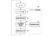
- FIG. 1 is a diagram showing an application example of a network management device according to an embodiment of the present invention.
- a network management device 100 according to one embodiment of the present invention includes a user input unit 10, a deployment plan processing unit 20, a total impact calculation unit 30, a failure impact calculation unit 40, and a deployment plan output unit 50.
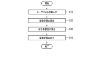
- FIG. 2 is a flowchart showing an example of a processing operation performed by the network management device according to an embodiment of the present invention.
- the user input unit 10 accepts information input by the user (S10).
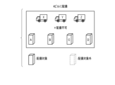
- FIG. 3 is a diagram illustrating an example of location information of a power supply vehicle and a building that has experienced a power outage.
- the user input unit 10 accepts input by the user of location information of the power supply vehicle (reference symbol a in FIG. 3 ) and location information of the power-failed building (reference symbol b in FIG. 3 ), for example, location information of power supply vehicles X, Y, and Z as shown in FIG 3 , and location information of the power-failed buildings A, B, C, and D.
- the location information is, for example, latitude and longitude.
- FIG. 4 is a diagram showing an example of the current time and the predicted time of failure occurrence in each building in a table format.
- the user input unit 10 accepts input of the current time and the predicted failure time of each building by the user.
- the predicted failure time of a building is the time when the battery installed in the building where the power outage occurred is expected to run out, that is, the timing when work related to recovery from the failure in the power supply to the communication equipment housed in the building needs to be performed.
- buildings A and B are predicted to run out of battery power three hours after the current time
- building C is predicted to run out of battery power six hours after the current time
- building D is predicted to run out of battery power eight hours after the current time.
- FIG. 5 is a diagram showing an example of various parameters in a table format.
- the user input unit 10 accepts input of various parameters by the user. These parameters may be stored as setting values in a storage device (not shown), eliminating the need for user input.
- the various parameters include the time interval ⁇ t for calculating the impact on communication services when a failure occurs, the number of times T for calculating the impact on communication services when a failure occurs, and the time discount rate ⁇ .
- the deployment plan processing unit 20 assumes that power supply vehicles have been deployed in some of the multiple buildings experiencing power outages and other faults, and calculates a deployment plan indicating which buildings experiencing power outages should have each power supply vehicle deployed to, for example, by using an existing solver (S20).
- the deployment plan processing unit 20 can calculate a deployment plan that minimizes the total travel distance of each power supply vehicle under the constraint that "one power supply vehicle can be deployed to only one power outage building.”
- 6 and 7 are diagrams showing an example of the results of calculation of the deployment plan of power supply vehicles for buildings. 6 shows that the three power supply vehicles X, Y, and Z cannot be deployed to all of the four power-failed buildings A, B, C, and D that are the deployment targets, i.e., deployment is not possible. Note that, due to the above constraints, in the example shown in FIG. 6, the number of power-failed buildings that are the deployment targets is greater than the number of available power supply vehicles, so it is self-evident that deployment is not possible, and calculation of the deployment plan may be omitted.
- the deployment plan processing unit 20 calculates a plan for deploying three power supply vehicles X, Y, and Z one-to-one to the three power outage buildings to be deployed.
- this deployment plan it is assumed that each power supply vehicle can arrive at the building to which it is deployed before the battery power runs out.
- FIG. 7(a) a plan is shown in which power supply vehicles X, Y, and Z are deployed in a one-to-one relationship to power-discharged buildings A, B, and C, respectively
- FIG. 7(b) a plan is shown in which power supply vehicles X, Y, and Z are deployed in a one-to-one relationship to power-discharged buildings A, B, and D, respectively.
- FIG. 7 shows a plan in which power supply vehicles X, Y, and Z are deployed in a one-to-one relationship to power-discharged buildings A, C, and D, respectively, and (d) of FIG. 7 shows a plan in which power supply vehicles X, Y, and Z are deployed in a one-to-one relationship to power-discharged buildings B, C, and D, respectively.
- the deployment plan processing unit 20 may calculate a plan in which, for example, two of the three available power supply vehicles are deployed in a one-to-one relationship to two power-dissipating buildings that are the target for deployment.
- the failure impact calculation unit 40 obtains information on the combination of buildings calculated by the deployment plan processing unit 20 as the deployment destination in the deployment plan of the power supply vehicle via the total impact calculation unit 30 or directly from the deployment plan processing unit 20, calculates the failure impact for each specified evaluation item for this combination, and calculates the impact on the communication service after a specified time has elapsed from the current time in the time interval in which the input was accepted by the user input unit 10, i.e., the time-series impact, by weighting and summing the calculated failure impacts.
- This impact can be calculated based on the failure status at that time using known technology, for example, the priority calculation technology described in the PCT/JP2021/022172 specification.
- the above evaluation item is, for example, the number of users affected by the failure of a specified communication service.
- the overall impact calculation unit 30 uses the current time when the input was received by the user input unit 10, the predicted time when the battery level of each powered out building will reach 0, and the various parameters described above to calculate an overall impact, which is an index used to determine the targets for which the above work should actually be performed as a priority, for each combination of buildings calculated by the deployment plan processing unit 20 as the deployment destinations for the power supply vehicles in the deployment plan, according to the following formula (2) (S30).
- FIG. 8 is a diagram showing an example of the calculation result of the total influence degree in a table format.
- FIG. 8 shows an example of the overall impact level indicating the impact on communication services provided by communication equipment housed in multiple buildings consisting of buildings A, B, C, D and other buildings, when it is assumed that a power supply vehicle is deployed in each of multiple combinations of three buildings out of buildings A, B, C, and D, which are candidates for the deployment of a power supply vehicle (here, four pattern combinations).
- the overall impact calculation unit 30 calculates the overall impact when it is assumed that power supply vehicles are deployed in each of buildings A, B, and D as the lowest overall impact compared to the overall impacts when it is assumed that power supply vehicles are deployed in each of other types of combinations of buildings.
- the deployment plan output unit 50 determines the combination associated with the lowest overall impact among the overall impacts calculated by the overall impact calculation unit 30 for each of the multiple combinations of buildings to be deployed as the priority deployment destination for the power supply vehicle, i.e., determines the power supply equipment housed in each of the relevant buildings as the target for actually carrying out the above-mentioned work with priority, and outputs a plan for deploying the power supply vehicle to the above-mentioned determined deployment destination.
- the deployment plan output unit 50 can output a plan for preferentially deploying power supply vehicles to the deployment targets "Building A, Building B, and Building D" associated with the lowest total impact degree of "108.8,” taking into consideration both the importance and urgency described above.
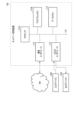
- FIG. 9 is a block diagram showing an example of a hardware configuration of the network management device 100 according to an embodiment of the present invention.
- the network management device 100 is configured, for example, by a server computer or a personal computer, and has a hardware processor 111A such as a CPU.
- a program memory 111B, a data memory 112, an input/output interface 113, and a communication interface 114 are connected to this hardware processor 111A via a bus 115.
- the communication interface 114 includes, for example, one or more wireless communication interface units, and enables the transmission and reception of information to and from a communication network NW.
- a wireless interface for example, an interface that adopts a low-power wireless data communication standard such as a wireless LAN (Local Area Network) is used.
- An input device 200 and an output device 300 that are attached to the network management device 100 and used by a user or the like are connected to the input/output interface 113 .
- the input/output interface 113 takes in operation data input by a user or the like through an input device 200 such as a keyboard, a touch panel, a touchpad, a mouse, or the like, and outputs output data to an output device 300 including a display device using liquid crystal or organic EL (Electro Luminescence), etc., for display.
- the input device 200 and the output device 300 may be devices built into the network management device 100, or may be input devices and output devices of other information terminals that can communicate with the network management device 100 via the network NW.
- the program memory 111B is a non-transient tangible storage medium that combines a non-volatile memory such as a HDD (Hard Disk Drive) or SSD (Solid State Drive) that can be written to and read from at any time, with a non-volatile memory such as a ROM (Read Only Memory), and stores the programs necessary to execute various control processes, etc. according to one embodiment.
- a non-volatile memory such as a HDD (Hard Disk Drive) or SSD (Solid State Drive) that can be written to and read from at any time
- a non-volatile memory such as a ROM (Read Only Memory)
- ROM Read Only Memory
- the data memory 112 is a tangible storage medium that combines, for example, the above-mentioned non-volatile memory with a volatile memory such as RAM (Random Access Memory), and is used to store various data acquired and created during various processing steps.
- RAM Random Access Memory
- the network management device 100 can be configured as a data processing device having a processing function unit implemented by software.
- the storage device used as a work memory or the like by the network management device 100 may be configured by using the data memory 112 shown in Fig. 9.
- these configured storage areas are not essential components within the network management device 100, and may be areas provided in a storage device such as an external storage medium such as a Universal Serial Bus (USB) memory, or a database server located in the cloud.
- USB Universal Serial Bus
- the above processing function unit can be realized by having the above hardware processor 111A read and execute a program stored in the program memory 111B. Note that this processing function unit may also be realized in a variety of other forms, including integrated circuits such as an application specific integrated circuit (ASIC (Application Specific Integrated Circuit)) or an FPGA (Field-Programmable Gate Array).
- ASIC Application Specific Integrated Circuit
- FPGA Field-Programmable Gate Array
- the methods described in each embodiment can be stored as a program (software means) that can be executed by a computer on a recording medium such as a magnetic disk (floppy disk, hard disk, etc.), optical disk (CD-ROM, DVD, MO, etc.), semiconductor memory (ROM, RAM, Flash memory, etc.), and can be distributed by transmitting it via a communication medium.
- the programs stored on the medium also include a setting program that configures the software means (including not only execution programs but also tables and data structures) that the computer executes.
- the computer that realizes this device reads the program recorded on the recording medium, and in some cases configures the software means using the setting program, and executes the above-mentioned processing by having the operation controlled by this software means.
- the recording medium referred to in this specification is not limited to a recording medium for distribution, but also includes storage media such as a magnetic disk or semiconductor memory installed inside the computer or in a device connected via a network.
- the present invention is not limited to the above-described embodiments, and can be modified in various ways in the implementation stage without departing from the gist of the invention.
- the embodiments may also be implemented in appropriate combination, in which case the combined effects can be obtained.
- the above-described embodiments include various inventions, and various inventions can be extracted by combinations selected from the multiple constituent elements disclosed. For example, if the problem can be solved and an effect can be obtained even if some constituent elements are deleted from all the constituent elements shown in the embodiments, the configuration from which these constituent elements are deleted can be extracted as an invention.
- REFERENCE SIGNS LIST 100 network management device 10 user input unit 20 deployment plan processing unit 30 total impact calculation unit 40 failure impact calculation unit 50 deployment plan output unit
Landscapes
- Engineering & Computer Science (AREA)
- Computer Networks & Wireless Communication (AREA)
- Signal Processing (AREA)
- Management, Administration, Business Operations System, And Electronic Commerce (AREA)
Abstract
一実施形態に係るネットワーク管理装置は、通信設備が収容される複数の建物における停電が発生したと仮定した条件が適用されたときの、複数の建物のうち一部の建物に収容される通信設備への電源供給の作業の計画を生成する生成部と、生成された計画で示される、通信設備への作業が施されたと仮定した条件が適用されたときの、複数の建物にそれぞれ収容される通信設備による通信への時系列の影響度を算出し、影響度を、現在時刻から、計画で示される、通信設備への前記作業を施す必要があるタイミングまでの時間の短さに応じて割り引いた結果に基づいて、作業を実際に優先的に施す対象の決定に使用される指標を算出する算出部と、を有する。
Description
本発明の実施形態は、ネットワーク管理装置、方法およびプログラムに関する。
大規模な停電が発生した際、通信設備が収容されることで外部への通信を提供するビル(building)(以下、通信ビルまたは単にビルと称することがある)の通信設備への電源の供給を維持するために、停電に伴い非常用バッテリ(battery)(以下、単にバッテリと称することがある)で通信設備を稼働させている通信ビル(以下、停電ビルと称することがある)に移動電源車(以下、電源車と称することがある)を配備することができる。
このとき、ネットワーク(NW(network))の運用管理者は、利用可能な移動電源車を、どの通信ビルに配備するかを示す配備計画を、通信ビルの「重要性」と「緊急性」を総合的に判断して決定する必要がある。
上記の重要性は、通信ビルの非常用バッテリの残量が無くなることにより、ビルに収容されている通信設備の機能が停止したときに、通信サービス(service)に及ぼす影響の大きさに対応する。
多くのNWは冗長構成を有しているため、通信サービスへの影響は、機能が停止した通信ビルの組み合わせによって変化する。そのため、NW構成を考慮して通信サービスへの影響を算出し、この影響が極力小さくなるビルの組み合わせに、限られた数の移動電源車を配備することが望ましい。
多くのNWは冗長構成を有しているため、通信サービスへの影響は、機能が停止した通信ビルの組み合わせによって変化する。そのため、NW構成を考慮して通信サービスへの影響を算出し、この影響が極力小さくなるビルの組み合わせに、限られた数の移動電源車を配備することが望ましい。
上記の「緊急性」は、通信ビルの非常用バッテリの残量が無くなるまでの猶予時間の短さである。
非常用バッテリの残量が無くなるまでの猶予時間が比較的短い通信ビルは、この猶予時間が比較的長い通信ビルよりも比較的早いタイミング(timing)で通信設備の機能が停止するので、長時間にわたって通信サービスへ影響を及ぼす恐れがある。
また、配備計画が決定した時点から、ある程度の時間が経過すると、通信ビルが復電して電源車の配備が不要になる可能性があるため、非常用バッテリの残量が無くなるまでの猶予時間が比較的長い通信ビルは、この時間が比較的短い通信ビルと比較して通信サービスに実際に影響を及ぼす可能性が低い。
非常用バッテリの残量が無くなるまでの猶予時間が比較的短い通信ビルは、この猶予時間が比較的長い通信ビルよりも比較的早いタイミング(timing)で通信設備の機能が停止するので、長時間にわたって通信サービスへ影響を及ぼす恐れがある。
また、配備計画が決定した時点から、ある程度の時間が経過すると、通信ビルが復電して電源車の配備が不要になる可能性があるため、非常用バッテリの残量が無くなるまでの猶予時間が比較的長い通信ビルは、この時間が比較的短い通信ビルと比較して通信サービスに実際に影響を及ぼす可能性が低い。
このため、非常用バッテリの残量が無くなるまでの猶予時間が比較的短い通信ビルを優先して、限られた数の電源車を該当のビルに配備することが望ましい。
上記の「重要性」を考慮して配備計画を決定するには、停電等の障害が発生している複数のビルのうち一部のビルの障害を復旧させたと仮定したときの通信サービスへの影響度を算出し、この影響度が比較的小さくかつ、限られた車両で復旧可能な組み合わせを出力する技術がある。
上記の「緊急性」を考慮して、限られた数の電源車の配備計画を決定するには、バッテリ残量が無くなるまでの時間が比較的短いビルから順に電源車を配備してビルの障害を復旧する方法が考えられる。
西川 翔平(Syouhei NISHIKAWA)、佐藤 正崇(Masataka SATO)、村瀬 健司(Kenji MURASE)、深見 公彦(Kimihiko FUKAMI)、田山 健一(Kenichi TAYAMA)、「装置階梯を考慮したサービス影響把握方式の検討(Study on Method of Identifying Service Influence on Device Hierarchy)」、一般社団法人 電子情報通信学会(THE INSTITUTE OF ELECTRONICS, INFORMATION AND COMMUNICATION ENGINEERS)、信学技報(IEICE Technical Report)
上記の技術は、通信ビルの重要性と緊急性のいずれか一方を考慮した配備計画を出力するものであり、これらを総合的に考慮した配備計画を出力することはできない。
このため、通信ビルの重要性と緊急性を総合的に判断して配備計画を決めるには、従来の技術で出力された2つの配備計画を踏まえて、NWの運用管理者が判断することになり、そのためのスキル(skill(経験))が必要になる。
この発明は、上記事情に着目してなされたもので、その目的とするところは、ネットワーク構成にて通信の障害が発生したときに、この障害の復旧の対象を適切に特定することができるようにしたネットワーク管理装置、方法およびプログラムを提供することにある。
本発明の一態様に係るネットワーク管理装置は、通信設備が収容される複数の建物における停電が発生したと仮定した条件が適用されたときの、前記複数の建物のうち一部の建物に収容される通信設備への電源供給の作業の計画を生成する生成部と、前記生成部により生成された計画で示される、前記通信設備への前記作業が施されたと仮定した条件が適用されたときの、前記複数の建物にそれぞれ収容される通信設備による通信への時系列の影響度を算出し、前記影響度を、現在時刻から、前記計画で示される、前記通信設備への前記作業を施す必要があるタイミングまでの時間の短さに応じて割り引いた結果に基づいて、前記作業を実際に優先的に施す対象の決定に使用される指標を算出する算出部と、を備える。
本発明の一態様に係るネットワーク管理方法は、ネットワーク管理装置により行なわれる方法であって、通信設備が収容される複数の建物における停電が発生したと仮定した条件が適用されたときの、前記複数の建物のうち一部の建物に収容される通信設備への電源供給の作業の計画を生成することと、前記生成された計画で示される、前記通信設備への前記作業が施されたと仮定した条件が適用されたときの、前記複数の建物にそれぞれ収容される通信設備による通信への時系列の影響度を算出することと、前記影響度を、現在時刻から、前記計画で示される、前記通信設備への前記作業を施す必要があるタイミングまでの時間の短さに応じて割り引いた結果に基づいて、前記作業を実際に優先的に施す対象の決定に使用される指標を算出することと、を備える。
本発明によれば、ネットワーク構成にて通信の障害が発生したときに、この障害の復旧の対象を適切に特定することができる。
以下、図面を参照しながら、この発明に係わる一実施形態を説明する。
本実施形態では、ネットワーク管理装置は、通信設備が収容される複数の建物、ここでは複数のビルにおける停電等の障害が発生したために、これらのビルに収容される通信設備への通常の電源の供給が停止して非常用バッテリによる電源供給(以下、ビルへの非常用バッテリによる電源供給などと称することがある)が開始されたと仮定したときの、上記複数のビルのうち一部のビルに当該ビルに収容される通信設備への電源の継続的な供給を維持するまたは復旧させる作業として、当該ビルに移動電源車が配備されて当該ビルに収容される通信設備への継続的な電源供給(以下、ビルへの電源供給などと称することがある)が開始されたと仮定したときの、残りの継続的な電源供給が行なえない通信設備が収容されるビルに起因する、上記複数のビルにそれぞれ収容される通信設備による、ネットワーク全体における通信サービスへの影響度を時系列で算出する。
本実施形態では、ネットワーク管理装置は、通信設備が収容される複数の建物、ここでは複数のビルにおける停電等の障害が発生したために、これらのビルに収容される通信設備への通常の電源の供給が停止して非常用バッテリによる電源供給(以下、ビルへの非常用バッテリによる電源供給などと称することがある)が開始されたと仮定したときの、上記複数のビルのうち一部のビルに当該ビルに収容される通信設備への電源の継続的な供給を維持するまたは復旧させる作業として、当該ビルに移動電源車が配備されて当該ビルに収容される通信設備への継続的な電源供給(以下、ビルへの電源供給などと称することがある)が開始されたと仮定したときの、残りの継続的な電源供給が行なえない通信設備が収容されるビルに起因する、上記複数のビルにそれぞれ収容される通信設備による、ネットワーク全体における通信サービスへの影響度を時系列で算出する。
例えば、停電等の障害が発生した複数のビルの一部であるAビル、Bビル、およびCビルに移動電源車が配備されたと仮定して、ネットワーク管理装置は、時系列の影響度として、1時間後の通信サービスへの影響度、2時間後の通信サービスへの影響度、・・・及びT時間後の通信サービスへの影響度を算出する。
ネットワーク管理装置は、上記のように算出した時系列の影響度のそれぞれに、経過時間に応じた割引率である時間割引率γを適用し、これらの総和を総合影響度として算出する。
Aビル、Bビル、およびCビルに移動電源車が配備されたと仮定したときの総合影響度は、以下の式(1)のように算出され得る。
Aビル、Bビル、およびCビルに移動電源車が配備されたと仮定したときの総合影響度は、以下の式(1)のように算出され得る。
総合影響度=1時間後の通信サービスへの影響度×時間割引率γ1+2時間後の通信サービスへの影響度×時間割引率γ2+・・・+T時間後の通信サービスへの影響度×時間割引率γT …式(1)
ネットワーク管理装置は、上記の総合影響度を、移動電源車が配備するビルの組み合わせ毎に算出し、この組み合わせの中で総合影響度が比較的小さいビル組み合わせに電源車を配備する計画を出力する。
ネットワーク管理装置は、上記の総合影響度を、移動電源車が配備するビルの組み合わせ毎に算出し、この組み合わせの中で総合影響度が比較的小さいビル組み合わせに電源車を配備する計画を出力する。
本実施形態により、通信ビルの重要性と緊急性を総合的に考慮した、電源車の配備計画を出力できるので、NW運用管理者のスキルレス(skill-less)化が実現できる。
本実施形態では、上記のように通信サービスへの時系列影響度を算出することで、通信ビルの重要性を考慮でき、上記のように、時系列で算出した影響度に時間割引率を適用した上で合計値である総合影響度を算出して評価することで、通信ビルの緊急性を考慮できる。
図1は、本発明の一実施形態に係るネットワーク管理装置の適用例を示す図である。
図1に示すように、本発明の一実施形態に係るネットワーク管理装置100は、ユーザ(user)入力部10、配備計画処理部20、総合影響度算出部30、障害影響計算部40、および配備計画出力部50を備える。
図1に示すように、本発明の一実施形態に係るネットワーク管理装置100は、ユーザ(user)入力部10、配備計画処理部20、総合影響度算出部30、障害影響計算部40、および配備計画出力部50を備える。
図2は、本発明の一実施形態に係るネットワーク管理装置による処理動作の一例を示すフローチャートである。
まず、ユーザ入力部10は、ユーザによる情報入力を受け付ける(S10)。
図3は、電源車と停電ビルの位置情報の一例について説明する図である。
S10において、ユーザ入力部10は、ユーザによる、電源車(図3の符号a)の位置情報と、停電ビル(図3の符号b)の位置情報、例えば図3に示されるような電源車X、Y、およびZの位置情報と、停電ビルA、B、C、およびDの位置情報の入力を受け付ける。位置情報は例えば緯度経度である。
まず、ユーザ入力部10は、ユーザによる情報入力を受け付ける(S10)。
図3は、電源車と停電ビルの位置情報の一例について説明する図である。
S10において、ユーザ入力部10は、ユーザによる、電源車(図3の符号a)の位置情報と、停電ビル(図3の符号b)の位置情報、例えば図3に示されるような電源車X、Y、およびZの位置情報と、停電ビルA、B、C、およびDの位置情報の入力を受け付ける。位置情報は例えば緯度経度である。
図4は、現在時刻と各ビルの障害発生予想時刻の一例を表形式で示す図である。
S10において、ユーザ入力部10は、ユーザによる現在時刻、および各ビルの通信障害の発生予想時刻である障害発生予想時刻の入力を受け付ける。ビルの障害発生予想時刻は、停電が発生した該当のビルに搭載されるバッテリ残量が無くなることが予想される時刻、すなわちビルに収容される通信設備に対して電源の供給に係る障害の復旧に係る作業を施す必要があるタイミングである。
S10において、ユーザ入力部10は、ユーザによる現在時刻、および各ビルの通信障害の発生予想時刻である障害発生予想時刻の入力を受け付ける。ビルの障害発生予想時刻は、停電が発生した該当のビルに搭載されるバッテリ残量が無くなることが予想される時刻、すなわちビルに収容される通信設備に対して電源の供給に係る障害の復旧に係る作業を施す必要があるタイミングである。
図4に示された例では、ビルAおよびBでは現在時刻の3時間後にバッテリ残量が無くなることが予想され、ビルCでは現在時刻の6時間後にバッテリ残量が無くなることが予想され、ビルDでは現在時刻の8時間後にバッテリ残量が無くなることが予想されることが示される。
図5は、各種パラメータの一例を表形式で示す図である。
S10において、ユーザ入力部10は、ユーザによる各種パラメータの入力を受け付ける。このパラメータは、設定値として図示しない記憶装置に保持し、ユーザによる入力は不要としてもよい。
S10において、ユーザ入力部10は、ユーザによる各種パラメータの入力を受け付ける。このパラメータは、設定値として図示しない記憶装置に保持し、ユーザによる入力は不要としてもよい。
図5に示されるように、各種パラメータは、障害発生時の通信サービスへの影響度の計算に係る時間間隔Δt、障害発生時の通信サービスへの影響度を計算する回数T、および時間割引率γが挙げられる。図5に示された例では、1時間後から10時間後までの1時間ごとの影響度、すなわち10回分の時系列の影響度をもとに総合影響度が計算されることを意味する。
次に、配備計画処理部20は、停電等を伴う障害が発生している複数の停電ビルのうち一部のビルに電源車が配備されたと仮定し、各電源車を、どの停電ビルに配備するべきかを示す配備計画を、例えば既存のソルバ(solver)を利用して算出する(S20)。
例えば、配備計画処理部20は、「電源車1台が停電ビル1ヶ所のみに配備可能」という制約条件のもと、各電源車の移動距離の合計が最小になる配備計画を算出することができる。
なお、停電ビルへの配備不可の電源車の組み合わせについては、総合影響度の算出に用いられないものとする。
図6および図7は、ビルに対する電源車の配備計画算出結果の一例を示す図である。
図6に示された例では、3台の電源車X、Y、およびZを、配備対象である4つの停電ビルA、B、C、およびDの全てには配備できない事、すなわち配備不可が示される。なお、上記の制約条件から、図6に示された例では、利用可能な電源車の台数より配備対象の停電ビルの数が多いため、配備不可になることは自明のため、配備計画の算出は省略されてもよい。
図6に示された例では、3台の電源車X、Y、およびZを、配備対象である4つの停電ビルA、B、C、およびDの全てには配備できない事、すなわち配備不可が示される。なお、上記の制約条件から、図6に示された例では、利用可能な電源車の台数より配備対象の停電ビルの数が多いため、配備不可になることは自明のため、配備計画の算出は省略されてもよい。
また、図7に示された例では、3台の電源車X、Y、およびZのそれぞれが、配備対象である3つの停電ビルへ1対1で配備される計画が配備計画処理部20により算出された例が示される。この配備計画では、いずれの電源車も、配備先のビルのバッテリ残量が無くなる前に到着できるものとする。
図7の(a)では、電源車X、Y、およびZのそれぞれが、停電ビルA、B、およびCへ1対1で配備される計画が示され、図7の(b)では、電源車X、Y、およびZのそれぞれが、停電ビルA、B、およびDへ1対1で配備される計画が示される。
図7の(c)では、電源車X、Y、およびZのそれぞれが、停電ビルA、C、およびDへ1対1で配備される計画が示され、図7の(d)では、電源車X、Y、およびZのそれぞれが、停電ビルB、C、およびDへ1対1で配備される計画が示される。
ここでは、上記の制約条件下では、3台の電源車のそれぞれが、配備対象である3つの停電ビルへ1対1で配備される計画の例を示したが、この上記の制約条件下は、利用可能な電源車の数が配備対象のビルの数以上であれば、例えば利用可能な3台の電源車のうち2台の電源車が、配備対象である2つの停電ビルへ1対1で配備される計画が配備計画処理部20により算出されてもよい。
障害影響計算部40は、配備計画処理部20により電源車の配備計画での配備先として算出されたビルの組み合わせの情報を、総合影響度算出部30を介して、または配備計画処理部20から直接取得し、この組み合わせについて、所定の評価項目ごとの障害影響を算出し、この算出した障害影響に重み付けをして合計する事で、現在時刻からの、ユーザ入力部10により入力が受け付けられた時間間隔での所定時間経過後の通信サービスへの影響度、すなわち時系列の影響度を計算する。この影響度は、当該時刻での障害状況をもとに、既知の技術、例えばPCT/JP2021/022172明細書に記載される優先度算出の技術により算出することができる。上記評価項目は、例えば、所定の通信サービスの障害の影響を受けるユーザの数である。
この算出された影響度に基づいて、総合影響度算出部30は、ユーザ入力部10により入力が受け付けられた現在時刻、各停電ビルのバッテリ残量が0になる予想時刻、および上記の各種パラメータを用いて、配備計画処理部20により電源車の配備計画での配備先として算出されたビルの組み合わせのそれぞれについて、下記の式(2)に従って、上記作業を実際に優先的に施す対象の決定に使用される指標である総合影響度を算出する(S30)。

It:t時間後の通信サービスへの影響度
γ:時間割引率(0≦γ≦1)
γ:時間割引率(0≦γ≦1)
図8は、総合影響度の算出結果の一例を表形式で示す図である。
図8では、電源車の配備対象の候補である、ビルA、B、C、およびDのうち3つのビルの複数種類の組み合わせ、ここでは4パターン(pattern)の組み合わせのそれぞれについて電源車が配備されたと仮定したときの、上記ビルA、B、C、D、および他のビルでなる複数のビルに収容される通信設備による通信サービスに与える影響を示す総合影響度の例が示される。
この図8に示された例では、ビルA、B、およびDについて電源車がそれぞれ配備されたと仮定したときの総合影響度が、ビルの他の種類の組み合わせについて電源車がそれぞれ配備されたと仮定したときの総合影響度と比較して最も低い総合影響度として総合影響度算出部30により算出された例が示される。
図8では、電源車の配備対象の候補である、ビルA、B、C、およびDのうち3つのビルの複数種類の組み合わせ、ここでは4パターン(pattern)の組み合わせのそれぞれについて電源車が配備されたと仮定したときの、上記ビルA、B、C、D、および他のビルでなる複数のビルに収容される通信設備による通信サービスに与える影響を示す総合影響度の例が示される。
この図8に示された例では、ビルA、B、およびDについて電源車がそれぞれ配備されたと仮定したときの総合影響度が、ビルの他の種類の組み合わせについて電源車がそれぞれ配備されたと仮定したときの総合影響度と比較して最も低い総合影響度として総合影響度算出部30により算出された例が示される。
次に、配備計画出力部50は、総合影響度算出部30により、配備対象のビルの複数種類の組み合わせのそれぞれについて算出された総合影響度のうち最も低い総合影響度に係る組み合わせを電源車の優先的な配備先として決定し、すなわち該当のビルのそれぞれに収容される電源設備を、実際に上記作業を優先的に施す対象として決定し、上記決定した配備先に電源車を配備する計画を出力する。
総合影響度が図8に示されるように総合影響度算出部30により算出されたときは、配備計画出力部50は、上記の重要性と緊急性の双方を考慮した、最も低い総合影響度「108.8」に係る配備対象「ビルA、ビルB、ビルD」に電源車を優先的に配備する計画を出力することができる。
図9は、本発明の一実施形態に係るネットワーク管理装置100のハードウエア構成の一例を示すブロック図である。
図9に示された例では、上記の実施形態に係るネットワーク管理装置100は、例えばサーバコンピュータ(server computer)またはパーソナルコンピュータ(personal computer)により構成され、CPU等のハードウエアプロセッサ(hardware processor)111Aを有する。そして、このハードウエアプロセッサ111Aに対し、プログラムメモリ(program memory)111B、データメモリ(data memory)112、入出力インタフェース113及び通信インタフェース114が、バス(bus)115を介して接続される。
図9に示された例では、上記の実施形態に係るネットワーク管理装置100は、例えばサーバコンピュータ(server computer)またはパーソナルコンピュータ(personal computer)により構成され、CPU等のハードウエアプロセッサ(hardware processor)111Aを有する。そして、このハードウエアプロセッサ111Aに対し、プログラムメモリ(program memory)111B、データメモリ(data memory)112、入出力インタフェース113及び通信インタフェース114が、バス(bus)115を介して接続される。
通信インタフェース114は、例えば1つ以上の無線の通信インタフェースユニット(interface unit)を含んでおり、通信ネットワーク(network)NWとの間で情報の送受信を可能にする。無線インタフェースとしては、例えば無線LAN(Local Area Network)などの小電力無線データ通信規格が採用されたインタフェースが使用される。
入出力インタフェース113には、ネットワーク管理装置100に付設される、利用者などにより用いられる入力デバイス(device)200および出力デバイス300が接続される。
入出力インタフェース113は、キーボード(keyboard)、タッチパネル(touch panel)、タッチパッド(touchpad)、マウス(mouse)等の入力デバイス200を通じて利用者などにより入力された操作データを取り込むとともに、出力データを液晶または有機EL(Electro Luminescence)等が用いられた表示デバイスを含む出力デバイス300へ出力して表示させる処理を行なう。なお、入力デバイス200および出力デバイス300には、ネットワーク管理装置100に内蔵されたデバイスが使用されてもよく、また、ネットワークNWを介してネットワーク管理装置100と通信可能である他の情報端末の入力デバイスおよび出力デバイスが使用されてもよい。
入出力インタフェース113は、キーボード(keyboard)、タッチパネル(touch panel)、タッチパッド(touchpad)、マウス(mouse)等の入力デバイス200を通じて利用者などにより入力された操作データを取り込むとともに、出力データを液晶または有機EL(Electro Luminescence)等が用いられた表示デバイスを含む出力デバイス300へ出力して表示させる処理を行なう。なお、入力デバイス200および出力デバイス300には、ネットワーク管理装置100に内蔵されたデバイスが使用されてもよく、また、ネットワークNWを介してネットワーク管理装置100と通信可能である他の情報端末の入力デバイスおよび出力デバイスが使用されてもよい。
プログラムメモリ111Bは、非一時的な有形の記憶媒体として、例えば、HDD(Hard Disk Drive)またはSSD(Solid State Drive)等の随時書込みおよび読出しが可能な不揮発性メモリ(non-volatile memory)と、ROM(Read Only Memory)等の不揮発性メモリとが組み合わせて使用されたもので、一実施形態に係る各種制御処理等を実行する為に必要なプログラムが格納されている。
データメモリ112は、有形の記憶媒体として、例えば、上記の不揮発性メモリと、RAM(Random Access Memory)等の揮発性メモリ(volatile memory)とが組み合わせて使用されたもので、各種処理が行なわれる過程で取得および作成された各種データが記憶される為に用いられる。
本発明の一実施形態に係るネットワーク管理装置100は、ソフトウエア(software)による処理機能部を有するデータ処理装置として構成され得る。
ネットワーク管理装置100によるワークメモリなどとして用いられる記憶装置は、図9に示されたデータメモリ112が用いられることで構成され得る。ただし、これらの構成される記憶領域はネットワーク管理装置100内に必須の構成ではなく、例えば、USB(Universal Serial Bus)メモリなどの外付け記憶媒体、又はクラウド(cloud)に配置されたデータベースサーバ(database server)等の記憶装置に設けられた領域であってもよい。
ネットワーク管理装置100によるワークメモリなどとして用いられる記憶装置は、図9に示されたデータメモリ112が用いられることで構成され得る。ただし、これらの構成される記憶領域はネットワーク管理装置100内に必須の構成ではなく、例えば、USB(Universal Serial Bus)メモリなどの外付け記憶媒体、又はクラウド(cloud)に配置されたデータベースサーバ(database server)等の記憶装置に設けられた領域であってもよい。
上記の処理機能部は、プログラムメモリ111Bに格納されたプログラムを上記ハードウエアプロセッサ111Aにより読み出させて実行させることにより実現され得る。なお、この処理機能部は、特定用途向け集積回路(ASIC(Application Specific Integrated Circuit))またはFPGA(Field-Programmable Gate Array)などの集積回路を含む、他の多様な形式によって実現されてもよい。
また、各実施形態に記載された手法は、計算機(コンピュータ)に実行させることができるプログラム(ソフトウエア手段)として、例えば磁気ディスク(フロッピー(登録商標)ディスク(Floppy disk)、ハードディスク(hard disk)等)、光ディスク(optical disc)(CD-ROM、DVD、MO等)、半導体メモリ(ROM、RAM、フラッシュメモリ(Flash memory)等)等の記録媒体に格納し、また通信媒体により伝送して頒布され得る。なお、媒体側に格納されるプログラムには、計算機に実行させるソフトウエア手段(実行プログラムのみならずテーブル(table)、データ構造も含む)を計算機内に構成させる設定プログラムをも含む。本装置を実現する計算機は、記録媒体に記録されたプログラムを読み込み、また場合により設定プログラムによりソフトウエア手段を構築し、このソフトウエア手段によって動作が制御されることにより上述した処理を実行する。なお、本明細書でいう記録媒体は、頒布用に限らず、計算機内部あるいはネットワークを介して接続される機器に設けられた磁気ディスク、半導体メモリ等の記憶媒体を含むものである。
なお、本発明は、上記実施形態に限定されるものではなく、実施段階ではその要旨を逸脱しない範囲で種々に変形することが可能である。また、各実施形態は適宜組み合わせて実施してもよく、その場合組み合わせた効果が得られる。更に、上記実施形態には種々の発明が含まれており、開示される複数の構成要件から選択された組み合わせにより種々の発明が抽出され得る。例えば、実施形態に示される全構成要件からいくつかの構成要件が削除されても、課題が解決でき、効果が得られる場合には、この構成要件が削除された構成が発明として抽出され得る。
100…ネットワーク管理装置
10…ユーザ入力部
20…配備計画処理部
30…総合影響度算出部
40…障害影響計算部
50…配備計画出力部
10…ユーザ入力部
20…配備計画処理部
30…総合影響度算出部
40…障害影響計算部
50…配備計画出力部
Claims (8)
- 通信設備が収容される複数の建物における停電が発生したと仮定した条件が適用されたときの、前記複数の建物のうち一部の建物に収容される通信設備への電源供給の作業の計画を生成する生成部と、
前記生成部により生成された計画で示される、前記通信設備への前記作業が施されたと仮定した条件が適用されたときの、前記複数の建物にそれぞれ収容される通信設備による通信への時系列の影響度を算出し、
前記影響度を、現在時刻から、前記計画で示される、前記通信設備への前記作業を施す必要があるタイミングまでの時間の短さに応じて割り引いた結果に基づいて、前記作業を実際に優先的に施す対象の決定に使用される指標を算出する算出部と、
を備えるネットワーク管理装置。 - 前記生成部は、
通信設備が収容される複数の建物における停電の発生により、前記通信設備への非常用電源設備による電源供給が開始されたと仮定した条件が適用されたときの、前記複数の建物のうち一部の建物であって、収容される通信設備への電源供給の維持または復旧に係る作業を施す対象の建物を定めた計画を生成し、
前記算出部は、
前記生成部により生成された計画で示される、前記作業を施す対象の建物に収容される通信設備への前記電源供給の維持または復旧に係る作業が施されたと仮定した条件が適用されたときの、現在時刻より後における、前記複数の建物にそれぞれ収容される通信設備による通信への時系列の影響度を算出し、
前記影響度を、現在時刻から、前記作業が施されないときに前記非常用電源設備による電源供給が停止するタイミングまでの時間に応じて割り引いた結果に基づいて、前記指標を算出する、
請求項1に記載のネットワーク管理装置。 - 前記生成部は、
前記複数の建物における停電が発生したと仮定した条件が適用されたときの、前記複数の建物のうち一部の建物であって、収容される通信設備への電源供給機器が搭載される車両の配備先の建物を定めた計画を生成し、
前記算出部は、
前記生成部により生成された計画で示される、前記作業の対象の建物に収容される通信設備への配備された車両に搭載される電源供給機器による電源供給に係る作業が施されたと仮定した条件が適用されたときの、前記複数の建物にそれぞれ収容される通信設備による通信への時系列の影響度を算出し、
前記影響度を、現在時刻から、前記作業の対象の建物に収容される通信設備への前記電源供給に係る作業を施す必要があるタイミングまでの時間の短さに応じて割り引いた結果に基づいて、前記指標を算出する、
請求項1に記載のネットワーク管理装置。 - 前記生成部は、
前記配備先の建物を定めた計画を、前記配備先の建物までの前記車両の移動距離が最小である計画として生成する、
請求項3に記載のネットワーク管理装置。 - 前記生成部は、
通信設備が収容される複数の建物における停電が発生したと仮定した条件が適用されたときの、前記複数の建物のうち一部の複数の建物の複数種類の組み合わせにそれぞれ収容される通信設備への電源供給の作業の計画を、複数種類の前記組み合わせのそれぞれについて生成し、
前記算出部は、
前記生成部により生成された計画で示される、前記通信設備への前記作業が施されたと仮定した条件が適用されたときの、前記一部の複数の建物の複数種類の組み合わせにそれぞれ収容される通信設備による通信への時系列の影響度を、前記複数の建物の複数種類の前記組み合わせのそれぞれについて算出し、
前記影響度を、現在時刻から、前記計画で示される、前記通信設備への前記作業を施す必要があるタイミングまでの時間の短さに応じて割り引いた結果に基づいて、前記指標を、前記複数の建物の複数種類の前記組み合わせのそれぞれについて算出し、
前記算出した指標のうち前記通信への影響が最も小さいときの前記複数の建物の組み合わせにそれぞれ収容される通信設備を、前記作業を実際に優先的に施す対象として決定する決定部をさらに備える、
請求項1に記載のネットワーク管理装置。 - ネットワーク管理装置により行なわれる方法であって、
通信設備が収容される複数の建物における停電が発生したと仮定した条件が適用されたときの、前記複数の建物のうち一部の建物に収容される通信設備への電源供給の作業の計画を生成することと、
前記生成された計画で示される、前記通信設備への前記作業が施されたと仮定した条件が適用されたときの、前記複数の建物にそれぞれ収容される通信設備による通信への時系列の影響度を算出することと、
前記影響度を、現在時刻から、前記計画で示される、前記通信設備への前記作業を施す必要があるタイミングまでの時間の短さに応じて割り引いた結果に基づいて、前記作業を実際に優先的に施す対象の決定に使用される指標を算出することと、
を備えるネットワーク管理方法。 - 前記生成することは、
通信設備が収容される複数の建物における停電の発生により、前記通信設備への非常用電源設備による電源供給が開始されたと仮定した条件が適用されたときの、前記複数の建物のうち一部の建物であって、収容される通信設備への電源供給の維持または復旧に係る作業を施す対象の建物を定めた計画を生成することを含み、
前記算出することは、
前記生成された計画で示される、前記作業を施す対象の建物に収容される通信設備への前記電源供給の維持または復旧に係る作業が施されたと仮定した条件が適用されたときの、現在時刻より後における、前記複数の建物にそれぞれ収容される通信設備による通信への時系列の影響度を算出することと、
前記影響度を、現在時刻から、前記作業が施されないときに前記非常用電源設備による電源供給が停止するタイミングまでの時間に応じて割り引いた結果に基づいて、前記指標を算出することと含む、
請求項6に記載のネットワーク管理方法。 - 請求項1乃至5のいずれか1項に記載のネットワーク管理装置の前記各部としてプロセッサを機能させるネットワーク管理処理プログラム。
Priority Applications (2)
| Application Number | Priority Date | Filing Date | Title |
|---|---|---|---|
| JP2024562500A JP7750433B2 (ja) | 2022-12-07 | 2022-12-07 | ネットワーク管理装置、方法およびプログラム |
| PCT/JP2022/045188 WO2024122004A1 (ja) | 2022-12-07 | 2022-12-07 | ネットワーク管理装置、方法およびプログラム |
Applications Claiming Priority (1)
| Application Number | Priority Date | Filing Date | Title |
|---|---|---|---|
| PCT/JP2022/045188 WO2024122004A1 (ja) | 2022-12-07 | 2022-12-07 | ネットワーク管理装置、方法およびプログラム |
Publications (1)
| Publication Number | Publication Date |
|---|---|
| WO2024122004A1 true WO2024122004A1 (ja) | 2024-06-13 |
Family
ID=91378822
Family Applications (1)
| Application Number | Title | Priority Date | Filing Date |
|---|---|---|---|
| PCT/JP2022/045188 Ceased WO2024122004A1 (ja) | 2022-12-07 | 2022-12-07 | ネットワーク管理装置、方法およびプログラム |
Country Status (2)
| Country | Link |
|---|---|
| JP (1) | JP7750433B2 (ja) |
| WO (1) | WO2024122004A1 (ja) |
Citations (3)
| Publication number | Priority date | Publication date | Assignee | Title |
|---|---|---|---|---|
| JP2012065422A (ja) * | 2010-09-15 | 2012-03-29 | Toshiba Corp | 情報通信装置および情報通信方法 |
| JP2015177665A (ja) * | 2014-03-17 | 2015-10-05 | 中国電力株式会社 | 災害復旧支援システムおよび災害復旧支援プログラム |
| WO2022130475A1 (ja) * | 2020-12-15 | 2022-06-23 | 日本電信電話株式会社 | ネットワーク管理装置、方法およびプログラム |
Family Cites Families (1)
| Publication number | Priority date | Publication date | Assignee | Title |
|---|---|---|---|---|
| JP2013030826A (ja) * | 2011-07-26 | 2013-02-07 | Ricoh Co Ltd | ネットワーク監視システム、ネットワーク監視方法 |
-
2022
- 2022-12-07 WO PCT/JP2022/045188 patent/WO2024122004A1/ja not_active Ceased
- 2022-12-07 JP JP2024562500A patent/JP7750433B2/ja active Active
Patent Citations (3)
| Publication number | Priority date | Publication date | Assignee | Title |
|---|---|---|---|---|
| JP2012065422A (ja) * | 2010-09-15 | 2012-03-29 | Toshiba Corp | 情報通信装置および情報通信方法 |
| JP2015177665A (ja) * | 2014-03-17 | 2015-10-05 | 中国電力株式会社 | 災害復旧支援システムおよび災害復旧支援プログラム |
| WO2022130475A1 (ja) * | 2020-12-15 | 2022-06-23 | 日本電信電話株式会社 | ネットワーク管理装置、方法およびプログラム |
Also Published As
| Publication number | Publication date |
|---|---|
| JP7750433B2 (ja) | 2025-10-07 |
| JPWO2024122004A1 (ja) | 2024-06-13 |
Similar Documents
| Publication | Publication Date | Title |
|---|---|---|
| US10567226B2 (en) | Mitigating risk and impact of server-change failures | |
| JP7452709B2 (ja) | ネットワーク管理装置、方法およびプログラム | |
| Silva et al. | Mercury: An integrated environment for performance and dependability evaluation of general systems | |
| US10585773B2 (en) | System to manage economics and operational dynamics of IT systems and infrastructure in a multi-vendor service environment | |
| US8799042B2 (en) | Distribution network maintenance planning | |
| US9514577B2 (en) | Integrating economic considerations to develop a component replacement policy based on a cumulative wear-based indicator for a vehicular component | |
| US9946981B2 (en) | Computing device service life management | |
| CN107729252B (zh) | 用于降低升级软件时的不稳定性的方法和系统 | |
| JP7589810B2 (ja) | ネットワーク管理装置、方法およびプログラム | |
| JP2025503990A (ja) | サイバー脆弱性に関してシステム・オブ・システムズを評価するためのシステムおよび方法 | |
| US9286735B1 (en) | Generating cumulative wear-based indicators for vehicular components | |
| US20120059684A1 (en) | Spatial-Temporal Optimization of Physical Asset Maintenance | |
| US20150073862A1 (en) | System and method for risk optimized, spatially sensitive preventive maintenance scheduling for asset management | |
| CN105741008A (zh) | 用于对于商业航线航班运营的中断管理和鲁棒性的自动评价的方法和系统 | |
| US11165665B2 (en) | Apparatus and method to improve precision of identifying a range of effects of a failure in a system providing a multilayer structure of services | |
| US9600795B2 (en) | Measuring process model performance and enforcing process performance policy | |
| Levitin et al. | Reliability of non-coherent warm standby systems with reworking | |
| Jafari et al. | Resilience-based optimal seismic retrofit and recovery strategies of bridge networks under mainshock–aftershock sequences | |
| US20110296249A1 (en) | Selecting a configuration for an application | |
| US8655812B2 (en) | Non-intrusive event-driven prediction | |
| US10467888B2 (en) | System and method for dynamically adjusting an emergency coordination simulation system | |
| JP7750433B2 (ja) | ネットワーク管理装置、方法およびプログラム | |
| US20240267283A1 (en) | Network management apparatus, method, and program | |
| CN112306744A (zh) | 一种日志存储备份方法、装置、服务器和介质 | |
| WO2024127508A1 (ja) | 配置最適化装置、配置最適化方法、および配置最適化プログラム |
Legal Events
| Date | Code | Title | Description |
|---|---|---|---|
| 121 | Ep: the epo has been informed by wipo that ep was designated in this application |
Ref document number: 22967853 Country of ref document: EP Kind code of ref document: A1 |
|
| WWE | Wipo information: entry into national phase |
Ref document number: 2024562500 Country of ref document: JP |
|
| NENP | Non-entry into the national phase |
Ref country code: DE |
|
| 122 | Ep: pct application non-entry in european phase |
Ref document number: 22967853 Country of ref document: EP Kind code of ref document: A1 |