WO2024121930A1 - 無線受電ユニットおよびその制御方法 - Google Patents
無線受電ユニットおよびその制御方法 Download PDFInfo
- Publication number
- WO2024121930A1 WO2024121930A1 PCT/JP2022/044882 JP2022044882W WO2024121930A1 WO 2024121930 A1 WO2024121930 A1 WO 2024121930A1 JP 2022044882 W JP2022044882 W JP 2022044882W WO 2024121930 A1 WO2024121930 A1 WO 2024121930A1
- Authority
- WO
- WIPO (PCT)
- Prior art keywords
- wireless power
- wave
- receiving unit
- unit
- transmission
- Prior art date
- Legal status (The legal status is an assumption and is not a legal conclusion. Google has not performed a legal analysis and makes no representation as to the accuracy of the status listed.)
- Ceased
Links
Images


















Classifications
-
- H—ELECTRICITY
- H02—GENERATION; CONVERSION OR DISTRIBUTION OF ELECTRIC POWER
- H02J—ELECTRIC POWER NETWORKS; CIRCUIT ARRANGEMENTS OR SYSTEMS FOR SUPPLYING OR DISTRIBUTING ELECTRIC POWER; SYSTEMS FOR STORING ELECTRIC ENERGY
- H02J50/00—Circuit arrangements or systems for wireless supply or distribution of electric power
- H02J50/20—Circuit arrangements or systems for wireless supply or distribution of electric power using microwaves or radio frequency waves
-
- H—ELECTRICITY
- H02—GENERATION; CONVERSION OR DISTRIBUTION OF ELECTRIC POWER
- H02J—ELECTRIC POWER NETWORKS; CIRCUIT ARRANGEMENTS OR SYSTEMS FOR SUPPLYING OR DISTRIBUTING ELECTRIC POWER; SYSTEMS FOR STORING ELECTRIC ENERGY
- H02J50/00—Circuit arrangements or systems for wireless supply or distribution of electric power
- H02J50/80—Circuit arrangements or systems for wireless supply or distribution of electric power involving the exchange of data, concerning supply or distribution of electric power, between transmitting devices and receiving devices
Definitions
- WPT Wireless Power Transfer
- electromagnetic induction type electromagnetic induction type
- magnetic field resonance type magnetic field coupling type
- electric field coupling type microwave spatial transmission type
- optical transmission type see Non-Patent Documents 1 and 2.
- the electromagnetic induction type, magnetic field resonance type (magnetic field coupling type), and electric field coupling type are classified as non-radiative WPT technologies, while the microwave spatial transmission type and optical transmission type are classified as radiative WPT technologies.
- the electromagnetic induction method is high power and highly efficient, but requires precise alignment.
- the magnetic field resonance method (magnetic field coupling method) is used for medium power and medium distances, and alignment is relatively easy.
- the electric field coupling method has a short transmission distance but can transmit high power.
- the microwave spatial transmission method allows long-distance transmission, but has low transmission efficiency.
- the optical transmission method has a longer transmission distance than the microwave spatial transmission method, and in principle has a higher transmission efficiency than the microwave spatial transmission method.
- the microwave spatial transmission method power is transmitted by a combination of a transmitting antenna and a receiving antenna.
- the optical transmission method power is transmitted by a combination of a semiconductor light source (usually a semiconductor laser) and a solar cell.
- This disclosure primarily relates to wireless power receiving units used in microwave spatial transmission systems, but is also applicable to wireless power receiving units used in other systems.
- such a wireless power supply unit is a wireless device that is not in close proximity to the wireless power receiving unit but is separated from it. Therefore, the wireless power receiving unit receives wireless power from microwaves transmitted from a wireless power supply unit (wireless device) that is not in close proximity but is separated from it. Therefore, it is different from techniques for transmitting power between devices that are in close proximity to each other (for example, inter-coil communication, electromagnetic induction, electromagnetic coupling, magnetic field resonance, electric field coupling, etc.) (for example, see Patent Documents 1 to 6).
- Non-Patent Document 3 proposes using several hundred ⁇ W of power obtained from radio waves for broadcasting and communication present in the environment as an energy source for driving a sensor network.
- Non-Patent Document 3 discloses the device configuration of a sensor node using energy harvesting. It also states the following: "A typical sensor node is composed of a sensor (depending on the application) that observes phenomena, an MCU and AD converter, a wireless interface, a communication antenna, and a storage element.
- the node assumed in this research uses an antenna not only for communication but also for obtaining power. Since the current that can be reproduced from the incoming radio waves at the receiving antenna is alternating current, it is necessary to convert it to direct current in practical use.
- a combination of an antenna and a rectifier circuit is called a rectenna.”
- Patent Document 7 also discloses a wireless power transmission system having a power receiving device and a power transmitting device.
- the wireless power transmission system disclosed in Patent Document 7 is a system that performs wireless power transmission using a magnetic field coupling method, in which the power receiving device has a power receiving coil and the power transmitting device has a power transmitting coil.
- the power transmitting device starts wireless power transmission to the power receiving device.
- Each of the power receiving device and the power transmitting device has a communication unit.
- the communication unit of the power receiving device performs wireless communication with the communication unit of the power transmitting device for controlling non-contact charging based on the WPC (Wireless Power Consortium) standard.
- WPC Wireless Power Consortium
- a method (first communication) of load modulating the electromagnetic waves received by the power receiving coil is used.
- the wireless communication by the communication unit of the power receiving device is not limited to the first communication, and a communication method (second communication) using a frequency different from the frequency for power transmission may be used.
- the communication unit of the power receiving device can perform the second communication using Near Field Communication (NFC), radio frequency identification (RFID), wireless LAN (Wi-Fi), Bluetooth (registered trademark), or the like.
- NFC Near Field Communication
- RFID radio frequency identification
- Wi-Fi wireless LAN
- Bluetooth registered trademark
- the power receiving device disclosed in Patent Document 7 is configured to appropriately control the timing of executing a request to stop power transmission.
- the power receiving device has a judgment unit, a decision unit, and a control unit.
- the judgment unit judges an authentication state including whether or not the power transmitting device supports a specified authentication (WPT authentication) and whether or not the specified authentication has been completed between the power transmitting device and the power receiving device.
- the decision unit decides the timing of making a request to stop power transmission by the power transmitting device based on the judged authentication state.
- the control unit requests the power transmitting device to stop power transmission at the decided timing.
- Patent Document 8 also discloses a "power transmission device and wireless power transmission system" that transmits power contactlessly by electromagnetic coupling between a power transmission coil and a power receiving coil.
- the power transmission device aligns the power transmission device with the power receiving device. Once alignment of the power transmission device and the power receiving device is complete, the power transmission device performs foreign object detection to determine whether or not a foreign object exists between the power transmission device and the power receiving device.
- Many devices that perform wireless charging transmit power in accordance with the Qi standard established by the WPC. In the Qi standard, when the power transmission device determines that no foreign object exists between the power transmission device and the power receiving device, it begins transmitting AC power contactlessly to the power receiving device.
- Patent Document 9 discloses a system and method for wireless power transmission.
- Patent Document 9 discloses an exemplary system for wireless power transmission using a pocket formation procedure.
- the system includes one or more transmitters, one or more receivers, and one or more client devices.
- the transmitter broadcasts a wireless power transmission signal, which may be an RF wave for wireless transmission.
- the transmitter can transmit the wireless power transmission in the form of an RF wave to the receiver, which may include any radio signal having any frequency or wavelength.
- the transmitter includes one or more antenna elements, one or more RFICs, one or more microcontrollers, one or more communication components, and a power source.
- the transmitter can transmit or otherwise broadcast controlled RF waves that converge at a location in three-dimensional space, thereby forming an energy pocket.
- the transmitter can scan for advertisement signals broadcast by the receiver, or the receiver can transmit advertisement signals to the transmitter.
- the advertisement signals can inform the transmitter of the presence of the receiver and can trigger an association between the transmitter and the receiver.
- the advertisement signals can communicate information that can be used by various devices (e.g., transmitters, client devices, server computers, other receivers) to perform and manage pocket formation procedures.
- Information contained within the advertisement signals can include device identifiers (e.g., MAC addresses, IP addresses, UUIDs), voltage of received electrical energy, client device power consumption, and other types of data related to the power transmission waves.
- the transmitter can use the transmitted advertisement signals to identify the receiver and, in some cases, locate the receiver in two-dimensional or three-dimensional space.
- technology is known for transmitting and receiving wireless power and information (data) via electromagnetic waves.
- technology is known for transmitting and receiving wireless power and information (data) via electromagnetic waves at different times using the same frequency (carrier frequency).
- Non-Patent Document 4 discloses a technology that uses microwaves in the same frequency band for power transmission and wireless communication, and schedules power transmission and communication in time.
- Patent document 10 also discloses a technique for efficiently transmitting power and data between a data relay device and a node using radio waves of a common frequency.
- the power transmission unit of the data relay device suspends transmission of a power transmission signal to the node during the period in which the control signal transmission unit transmits a control signal to the node.
- Kiyoshi Seko "The day when the world will no longer have power cords: A future where wireless power transmission is a reality," 2020-06-01 Akira Fukuda, “Basic Principles of Wireless Power Transmission (Part 2): Akira Fukuda's Device Communication (349) Imec Discusses Wireless Power Transmission Technology (3) - EE Times Japan,” March 7, 2022 Yoshihiro Kawahara and two others, “Quantitative Study on Energy Harvesting from Broadcasting and Communication Radio Waves," Transactions of the Information Processing Society of Japan, March 2010, Vol. 51, No. 3, pp. 824-834 Shota Yamashita and 5 others, “Remaining Energy Adaptive Scheduling for Battery-less Wireless LAN Using Microwave Power Transmission,” IEICE Technical Report, March 2013, pp. 40-45
- Non-Patent Document 3 and Patent Documents 7 to 9 disclose or suggest any technology for selectively transmitting wireless power wirelessly only to a specific wireless receiving unit (power receiving device; receiver) so that only the specific wireless receiving unit receives wireless power and/or prohibits reception of power.
- receiving wireless power means receiving wireless power and charging a secondary battery.
- prohibiting reception of power means prohibiting charging of the secondary battery even if wireless power is received.
- a capacitor may be used instead of a secondary battery.
- Non-Patent Document 3 merely describes how low-power electronic devices can be operated by obtaining the wireless power required for operation from the environmental electromagnetic field.
- Patent Document 7 when power is supplied from the AC adapter to the power transmitting device, the power transmitting device starts wireless power transmission to the power receiving device.
- the power supply is the trigger for wireless power transmission.
- Patent Document 8 when it is determined that no foreign object is present between the power transmitting device and the power receiving device, the power transmitting device starts transmitting AC power to the power receiving device in a non-contact manner.
- the transmitter simply locates the location of the receiver using the transmitted advertisement signal, but does not selectively transmit wireless power wirelessly to only a specific receiver.
- Non-Patent Document 3 and Patent Documents 7 to 9 allows anyone to receive wireless power transmitted from a wireless power supply unit using a wireless power receiving unit (rectenna; power receiving device; receiver) as long as they are equipped with the wireless power receiving unit. Furthermore, the technology disclosed in Non-Patent Document 3 and Patent Documents 7 to 9 does not disclose or suggest in any way how to prohibit power reception.
- Non-Patent Document 3 nor Patent Documents 7 to 9 disclose any technology for transmitting and receiving wireless power and information (data) via electromagnetic waves at different times using the same frequency (carrier frequency).
- Non-Patent Document 4 and Patent Document 10 disclose technology for transmitting and receiving wireless power and information (data) via electromagnetic waves at different times using the same frequency (carrier frequency).
- the wireless power receiving unit needs to determine whether the received waves are for power or communication.
- the objective of this disclosure is to provide a wireless power receiving unit that, when receiving a transmission wave including electromagnetic waves for power and electromagnetic waves for communication transmitted at different times from a wireless power supply unit, can switch between receiving waves for power and receiving waves for communication.
- a wireless power receiving unit that receives a transmission wave consisting of either a first transmission wave or a second transmission wave transmitted at different timings from a wireless power feeding unit as a reception wave having a reception power P R , the first transmission wave consisting of an electromagnetic wave for power transmission that is a first carrier wave having a first transmission power P T1 at a predetermined frequency, and the second transmission wave consisting of a second transmission power P T1 that is smaller than the first transmission power P T1 at the predetermined frequency.
- the wireless power receiving unit includes a communication electromagnetic wave which is a modulated wave obtained by modulating a second carrier wave having T2 with data, and the received wave includes either a first received wave or a second received wave which correspond to the first transmitted wave and the second transmitted wave, respectively, and the wireless power receiving unit includes: a determination means which determines whether the received wave is the first received wave or the second received wave and outputs the determination result as a switching control signal; a switching means which switches the received wave to either the first received wave or the second received wave based on the switching control signal, and outputs the switched received wave; and a demodulation device which demodulates the second received wave to restore the data.
- a control method for controlling a wireless power receiving unit that receives a transmission wave consisting of either a first transmission wave or a second transmission wave transmitted at different timings from a wireless power feeding unit as a reception wave having a reception power P R , the first transmission wave consisting of an electromagnetic wave for power transmission that is a first carrier wave having a first transmission power P T1 at a predetermined frequency, and the second transmission wave consisting of a second transmission power P T1 that is smaller than the first transmission power P T1 at the predetermined frequency.
- the wireless power receiving unit comprises an electromagnetic wave for communication, which is a modulated wave obtained by modulating a second carrier wave having T2 with data, and the received wave comprises either a first received wave or a second received wave corresponding to the first transmitted wave and the second transmitted wave, respectively, and the control method includes: determining whether the received wave is the first received wave or the second received wave, and outputting the determination result as a switching control signal; switching the received wave to either the first received wave or the second received wave based on the switching control signal, and outputting the switched received wave; demodulating the second received wave with a demodulation device to restore the data; and a control method for a wireless power receiving unit is obtained.
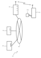
- FIG. 1 is a schematic diagram showing a schematic configuration of a wireless power transmission system according to a first embodiment of the present disclosure.
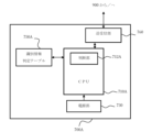
- 2 is a block diagram showing an example of the internal configuration of a wireless power receiving unit and an identification member used in the wireless power transmission system shown in FIG. 1 .
- 3 is a block diagram showing the configuration of a first RFID interface unit used in the wireless power receiving unit shown in FIG. 2.
- 2 is a block diagram showing an example of an internal configuration of a wireless power supply unit used in the wireless power transmission system shown in FIG. 1 .
- 5 is a block diagram showing an example of an internal configuration of a second transceiver unit used in the wireless power supply unit shown in FIG. 4 .
- FIG. 3 is a block diagram showing an example of an internal configuration of a first transceiver unit used in the wireless power receiving unit shown in FIG. 2 .
- FIG. 4 is a block diagram showing a determination means according to the first example.
- FIG. 11 is a block diagram showing a determination means according to a second example.
- FIG. 11 is a block diagram showing a determination means according to a third example.
- 10 is a circuit diagram showing an example of a signal determiner shown in FIG. 9 .
- 10 is a circuit diagram showing another example of the signal determiner shown in FIG. 9 .
- 3 is a diagram showing an example in which the wireless power receiving unit shown in FIG. 2 is realized in the form of a smartphone, and the identification member is realized in the form of an R badge.
- FIG. 13 is a diagram showing the smartphone shown in FIG. 12 and an R badge having an IC chip built therein.
- FIG. 2 is a diagram showing an example of a first type R badge.
- FIG. 13 is a diagram showing an example of a second type of R badge. A figure showing another example of the second type of R badge.
- FIG. 13 is a diagram showing an example of a third type of R badge. A figure showing another example of the third type R badge.
- 15 is a diagram showing in detail the external appearance of the R badge shown in FIG. 14 and the internal configuration of an IC chip built into the R badge.
- 11 is a diagram showing a wireless power receiving unit (smartphone) and an R badge for explaining a second modified example of the first embodiment of the present disclosure.
- FIG. 13 is a schematic diagram showing a schematic configuration of a billing system according to a third modified example of the first embodiment of the present disclosure.
- 22 is a block diagram showing an example of the configuration of a management server used in the billing system shown in FIG. 21.
- 23 is a diagram showing an example of a power consumption amount management table used in the management server shown in FIG. 22.
- FIG. FIG. 11 is a schematic diagram showing a schematic configuration of a wireless power transmission system according to a second embodiment of the present disclosure.
- 25 is a block diagram showing an example of the internal configuration of a wireless power receiving unit and an identification member used in the wireless power transmission system shown in FIG. 24.
- 26 is a diagram showing an example in which the wireless power receiving unit shown in FIG.
- FIG. 25 is realized in the form of a smartphone, and the identification member is realized in the form of a recording medium.
- FIG. FIG. 27 is a diagram showing an example of the recording medium shown in FIG. 26.
- FIG. 13 is a schematic diagram showing a schematic configuration of a billing system according to a fourth modified example of the second embodiment of the present disclosure.
- FIG. 13 is a schematic diagram showing a schematic configuration of a wireless power transmission system according to a third embodiment of the present disclosure.
- 30 is a block diagram showing an example of the internal configuration of a wireless power receiving unit used in the wireless power transmission system shown in FIG. 29 .
- FIG. 31 is a diagram showing an example in which the wireless power receiving unit shown in FIG. 30 is realized in the form of a smartphone.
- FIG. 13 is a schematic diagram showing a schematic configuration of a billing system according to a fifth modified example of the third embodiment of the present disclosure.
- FIG. 13 is a schematic diagram showing a schematic configuration of a wireless power transmission system according to a fourth embodiment of the present disclosure.
- 34 is a block diagram showing an example of the internal configuration of a wireless power receiving unit used in the wireless power transmission system shown in FIG. 33.
- FIG. 35 is a diagram showing an example in which the wireless power receiving unit shown in FIG. 34 is realized in the form of a smartphone.
- FIG. 36 is a diagram showing an example in which the charging instruction button shown in FIG. 35 is realized as a “wireless power supply” button.
- FIG. 34 is a block diagram showing an example of the internal configuration of a wireless power receiving unit used in the wireless power transmission system shown in FIG. 33.
- FIG. 35 is a diagram showing an example in which the wireless power receiving unit shown in FIG. 34 is realized in the form of a smartphone.
- FIG. 36 is a diagram showing an
- FIG. 13 is a schematic diagram showing a schematic configuration of a billing system according to a sixth modified example of the fourth embodiment of the present disclosure.
- FIG. 13 is a schematic diagram showing a schematic configuration of a wireless power transmission system according to a fifth embodiment of the present disclosure.
- 39 is a block diagram showing an example of the internal configuration of a wireless power receiving unit used in the wireless power transmission system shown in FIG. 38.
- FIG. 13 is a schematic diagram showing a schematic configuration of a wireless power transmission system according to a sixth embodiment of the present disclosure.
- 42 is a block diagram showing an example of the internal configuration of a wireless power receiving unit used in the wireless power transmission system shown in FIG. 41.
- FIG. 13 is a schematic diagram showing a schematic configuration of a wireless power transmission system according to a seventh embodiment of the present disclosure.
- 45 is a block diagram showing an example of the internal configuration of a wireless power receiving unit used in the wireless power transmission system shown in FIG. 44.
- 47 is a diagram showing an example of a power receiving right management table used in the management server shown in FIG. 46.
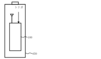
- FIG. 13 is a diagram showing an outline of a battery-powered electronic device (battery-shaped unit) according to an eighth embodiment of the present disclosure.
- FIG. 48B is a diagram showing an outline of a modified example of the battery-powered electronic device (battery-shaped unit) shown in FIG. 48A.
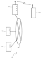
- FIG. 1 is a diagram showing a schematic configuration of a satellite constellation that can be used as a wireless power transmission system according to the present disclosure.
- First Embodiment 1 is a schematic diagram showing a schematic configuration of a wireless power transmission system 10 according to a first embodiment of the present disclosure.
- the illustrated wireless power transmission system 10 includes a wireless power receiving unit 100, a wireless power feeding unit 200, and an identification member 300.
- the illustrated wireless power transmission system 10 is a system that selectively transmits wireless power from the wireless power feeding unit 200 to the wireless power receiving unit 100 by electromagnetic waves.
- an identification member 300 is used, as described below.
- the wireless power receiving unit 100 when the wireless power receiving unit 100 is identified by the identification member 300, as described later, the wireless power receiving unit 100 transmits an information transmission signal including a wireless power supply permission signal S alw or a wireless power stop request signal S stp to the wireless power receiving unit 200.
- the wireless power feeding unit 200 transmits wireless power to the wireless power receiving unit 100 by electromagnetic waves.
- the wireless power receiving unit 100 receives this power and charges a secondary battery (battery) described later.
- the wireless power feeding unit 200 stops transmitting wireless power to the wireless power receiving unit 100 by electromagnetic waves.
- the wireless power receiving unit 100 determines that the secondary battery (battery) has been charged with a predetermined amount of power (for example, a fully charged amount)
- the wireless power receiving unit 100 also transmits an information transmission signal including the wireless power stop request signal S stp to the wireless power feeding unit 200.
- the predetermined amount can be set by initial settings or application settings.
- the wireless power feeding unit 200 stops transmitting wireless power to the wireless power receiving unit 100 by electromagnetic waves.
- the wireless power transmission system 10 of the first embodiment it is possible to selectively transmit wireless power only to a specific wireless power receiving unit 100.
- the wireless power supply unit 200 may be fixed or mobile.
- the wireless power supply unit 200 may be composed of a base station, as described below.
- the wireless power supply unit 200 transmits not only wireless power but also information (data) by electromagnetic waves.
- the electromagnetic waves may be, for example, microwaves.
- the base station is not limited to a fixed base station, but may be a mobile base station.
- the wireless power supply unit 200 may be a low earth orbit satellite (LEO: Low Earth Orbit).
- the illustrated wireless power receiving unit 100 receives a transmission wave consisting of either a first transmission wave or a second transmission wave transmitted from the wireless power supply unit 200 at different timings as a reception wave having a reception power P R.
- the first transmission wave consists of an electromagnetic wave for power transmission, which is a first carrier wave having a first transmission power P T1 at a predetermined frequency.
- the second transmission wave consists of an electromagnetic wave for communication, which is a modulated wave obtained by modulating a second carrier wave having a second transmission power P T2 smaller than the first transmission power P T1 at a predetermined frequency with data (P T1 >P T2 ).
- the reception wave consists of either a first reception wave or a second reception wave corresponding to the first transmission wave and the second transmission wave, respectively.
- the second transmission power P T2 of the second transmission wave is set so that the second receiving power P R2 of the second receiving wave is equal to or greater than the lower limit power P LL at which data can be demodulated from the second receiving wave in the demodulation device described below (P R2 ⁇ P LL ).
- the wireless power receiving unit 100 has a first RFID interface and a secondary battery, as described below.
- the wireless power receiving unit 100 is configured to be able to receive wireless power from the wireless power supply unit 200 via electromagnetic waves (first transmission waves) and charge the secondary battery.
- the wireless power receiving unit 100 may be, for example, a mobile terminal such as a smartphone, a mobile phone, a PDA (personal digital assistant), a laptop, or a personal computer.
- the wireless power receiving unit 100 is not limited to these mobile terminals, but may be built into an electronic device (hereinafter referred to as a "battery-powered electronic device") that has a secondary battery (capacitor) for operation.
- the battery-powered electronic device is not limited to a mobile device, but may be fixed.
- the size of the secondary battery mounted inside the battery-powered electronic device is not particularly limited. For example, in mountainous areas or on the ocean, it may be impossible to lay a power transmission line.
- the wireless power transmission system 10 can supply power to a battery-powered electronic device installed in a place where such a power transmission line cannot be laid.
- the battery-powered electronic device may be, for example, a drone, an Internet of Things (IoT) device, an electric vehicle, or the like.
- IoT Internet of Things
- LEO low earth orbit satellite
- RFID Radio Frequency Identification
- RFID interfaces have various modulation methods, frequencies, and communication protocols. From the standpoint of standardization, it is preferable to have an RFID interface that conforms to ISO/IEC 10536 for close contact type, ISO/IEC 14443 for close proximity type, and ISO/IEC 15693 for nearby type. Possible carrier frequencies include 125 kHz to 400 kHz, 4.9152 MHz, 13.56 MHz, and 2.45 GHz.
- the RFID interface may preferably consist of an NFC (Near Field Communication) interface.
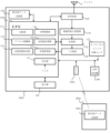
- FIG. 2 is a block diagram showing an example of the internal configuration of the wireless power receiving unit 100 and the identification member 300 used in the wireless power transmission system 10 shown in FIG. 1.
- the wireless power receiving unit 100 shown in the figure is a smartphone.
- the wireless power receiving unit 100 includes a first CPU (Central Processing Unit) 110, a first RFID interface unit (I/F) 120, a secondary battery 130, a charging unit 132, a display unit 140, a first matching data recording unit 150, a first transmitting/receiving unit 160, an electromagnetic wave power converter 170, and a touch panel, switch, and various sensors 175.
- the secondary battery 130 is, for example, a lithium ion battery.
- the illustrated wireless power receiving unit 100 is a smartphone. It should be noted that commercially available, well-known smartphones already have hardware elements other than the electromagnetic wave power converter 170. In other words, the illustrated wireless power receiving unit 100 is configured by further incorporating the electromagnetic wave power converter 170 in a commercially available smartphone.
- the electromagnetic wave power converter 170 for example, a rectifier circuit such as that described in the above-mentioned non-patent document 3 can be used.
- the first CPU 110 and the first transmission/reception unit 160 have also been slightly modified from existing ones, as will be described later.
- the identification member 300 includes a second CPU 310, a second RFID interface unit (I/F) 320, and a second matching data recording unit 350.
- the wireless power receiving unit 100 and the identification member 300 are configured to be able to transmit and receive data without contact, as described below.
- the first CPU 110 controls each component of the wireless power receiving unit 100.
- the second CPU 310 controls each component of the identification member 300.
- the first RFID interface unit 120 and the second RFID interface unit 320 each have a transmission function and a reception function.
- the first RFID interface unit 120 and the second RFID interface unit 320 are composed of, for example, a coil, and transmit and receive data to and from each other.
- the first matching data recording unit 150 and the second matching data recording unit 350 each record matching data for matching the wireless power receiving unit 100 and the identification member 300.
- the matching data recorded in the second matching data recording unit 350 is called "first identification information”
- the matching data recorded in the first matching data recording unit 150 is called "second identification information”.
- the first identification information is information assigned so that the identification member 300 can be uniquely identified.
- the first identification information is information that can uniquely identify the user (owner) of the wireless power receiving unit 100.
- the first identification information may be written to be unique when the identification member 300 is manufactured.
- the second identification information is information that is registered in advance in the wireless power receiving unit 100, as described below, and is the same information as the first identification information. Therefore, the identification member 300 and the wireless power receiving unit 100 owned by the same owner are assigned the same identification information, the first identification information and the second identification information, respectively.
- the first CPU 110 includes a receiving unit 111.
- the receiving unit 111 receives a trigger signal.
- the trigger signals are classified into an on trigger signal and an off trigger signal.
- the on trigger signal is a signal for turning on the power receiving state of the wireless power receiving unit 100.
- the off trigger signal is a signal for turning off the power receiving state of the wireless power receiving unit 100.
- the wireless power receiving unit 100 is in the power receiving OFF state. In this initial state (power receiving OFF state), the on trigger signal is generated, for example, when the user (owner) of the wireless power receiving unit 100 presses a trigger switch (described later). As a result, the wireless power receiving unit 100 switches from the power receiving OFF state to the power receiving ON state.
- the off trigger signal is generated when the user (owner) of the wireless power receiving unit 100 presses the trigger switch again.
- This causes the wireless power receiving unit 100 to switch (return) from an ON state of power receiving to an OFF state of power receiving.
- a trigger switch can be realized, for example, by a toggle switch (toggle button). That is, the user (owner) of the wireless power receiving unit 100 can switch between the ON and OFF states of power receiving in the wireless power receiving unit 100 by repeatedly pressing the toggle switch (toggle button).
- the wireless power receiving unit 100 in the power receiving ON state, the wireless power receiving unit 100 is switched so that it can receive the first transmission wave transmitted from the wireless power supply unit 200 as the first reception wave.
- the wireless power receiving OFF state the wireless power receiving unit 100 is switched so that it can receive the second transmission wave transmitted from the wireless power supply unit 200 as the second reception wave. Note that, since the wireless power receiving unit 100 is normally in the power receiving OFF state, the wireless power receiving unit 100 receives the second transmission wave transmitted from the wireless power supply unit 200 as the second reception wave.
- the reception unit 111 receives the trigger signal as the on trigger signal, which is a first access request requesting to receive wireless power (i.e., the first transmission wave) from the wireless power supply unit 200. Thereafter, the wireless power supply unit 200 is switched from the power reception OFF state to the power reception ON state, as described below. Also, in the power reception ON state, the reception unit 111 receives the trigger signal as the off trigger signal, which is a second access request requesting to stop the supply of wireless power (the first transmission wave) from the wireless power supply unit 200. Thereafter, the wireless power supply unit 200 is switched from the power reception ON state to the power reception OFF state, as described below.
- the on trigger signal and the off trigger signal are not limited to signals generated by pressing a trigger switch.
- the current flowing through the wireless power receiving unit 100 may be used as the on trigger signal.
- the on/off operation (toggle operation) as described above may be controlled by an app.
- Such an app may be installed, for example, when the user (owner) of the wireless power receiving unit 100 applies for the power receiving function to a mobile phone operator.
- the mobile phone operator transmits a command (hereinafter referred to as an "ON command") to the wireless power receiving unit 100 to turn on the power receiving function of the wireless power receiving unit 100.
- the wireless power receiving unit 100 receives this ON command at the first transceiver unit 160, it issues an on trigger signal to the wireless receiving unit 100 as a trigger signal.
- the mobile phone operator wants to stop communication of the wireless power receiving unit 100 (smartphone) that has not been paid for.
- the mobile phone operator sends a command to the wireless power receiving unit 100 to turn off the power receiving function of the wireless power receiving unit 100 (hereinafter referred to as an "OFF command").
- the wireless power receiving unit 100 receives this OFF command at the first transceiver 160, it issues an OFF trigger signal as a trigger signal to the wireless power receiving unit 100.
- the stop condition is released, the mobile phone operator sends an ON command to the wireless power receiving unit 100.
- the trigger signal may be generated by internal processing by the first CPU 110 based on the received signal at the first RFID interface section 120, the photographed signal from the camera, the operation signal at the touch panel 175, the results of biometric authentication processing, the voice or facial expression of the user (owner) of the wireless power receiving unit 100, the received data at the first transceiver section 160, etc.
- the photographed signal from the camera, biometric authentication, voice, and facial expression will be described in detail later in another embodiment.
- FIG. 3 is a block diagram showing the configuration of the first RFID interface unit 120 shown in FIG. 2.
- the first RFID interface unit 120 has a sending unit 122 and a receiving unit 124.
- the sending unit 122 sends a request signal requesting the above-mentioned first identification information to the identification member 300.
- the receiving unit 124 receives the first identification information from the identification member 300.
- the first RFID interface unit 120 is composed of a coil. Therefore, this coil operates as the sending unit 122 and the receiving unit 124. Therefore, the combination of the sending unit 122 and the receiving unit 124 works as a reading unit that reads the first identification information from the identification member 300 in response to a trigger signal.
- the first CPU 110 includes a comparison unit 112.
- the comparison unit 112 compares the read first identification information with the second identification information previously recorded in the first matching data recording unit 150.
- the first CPU 110 includes an access control unit 113, a charge amount measurement unit 114, and a charge monitoring unit 115.
- the access control unit 113 permits or prohibits the first or second access request received by the reception unit 111 according to a comparison result by the comparison unit 112.
- the first CPU 110 controls the first transmission/reception unit 160 to transmit an information transmission signal including the wireless power supply permission signal S alw or the wireless power stop request signal S stp toward the wireless power supply unit 200.
- the first transceiver 160 functions as a transmitter that transmits an information transmission signal including the wireless power supply permission signal S alw or the wireless power stop request signal S stp to the wireless power supply unit 200.
- the internal configuration of the first transceiver 160 will be described in detail later with reference to the drawings.
- the wireless power receiving unit 100 is in an OFF state (initial state) of power reception. It is also assumed that the access control unit 113 obtains a comparison result that the first access request is permitted. In this case, the first transmitting/receiving unit 160 transmits an information transmission signal including the wireless power supply permission signal S alw to the wireless power supply unit 200. After transmitting this information transmission signal, the charge amount measuring unit 114 measures the charge amount charged to the secondary battery 130 by the charging unit 132. The charge monitoring unit 115 monitors the charge (charge state; remaining amount) of the secondary battery 130 as described later.
- the display unit 140 has a function to display the charging state of the secondary battery 130 as described below, and a function to display the power receiving state of the wireless power receiving unit 100.
- the display unit 140 may display the charging state of the secondary battery 130 with an icon, or may display the charging state of the secondary battery 130 on the display screen as a graph or the like. Displaying the "charging state” means, for example, displaying the remaining charge (remaining capacity) of the secondary battery 130 as a percentage. Also, when the wireless power receiving unit 100 is receiving power, the display unit 140 may display a power receiving icon.
- FIG. 4 is a block diagram showing an example of the internal configuration of the wireless power supply unit 200 used in the wireless power transmission system 10 shown in FIG. 1.
- the wireless power supply unit 200 includes a third CPU 210, a first power supply unit 230, and a second transceiver unit 260.
- the second transceiver 260 receives an information transmission signal including the wireless power supply permission signal S alw from the wireless power receiving unit 100.
- the received information transmission signal including the wireless power supply permission signal S alw is sent to the third CPU 210.
- the third CPU 210 controls the second transceiver 260 to transmit power from the first power supply unit 230 as electromagnetic waves (first transmission waves) to the wireless power receiving unit 100. Therefore, the second transceiver 260 functions as a power transmitting unit that transmits wireless power to the wireless power receiving unit 100 as electromagnetic waves (first transmission waves).
- FIG. 5 is a block diagram showing an example of the configuration of the second transmission/reception unit 260.
- the second transmission/reception unit 260 functions as a modulation/demodulation device.
- the second transmission/reception unit 260 comprises a transmission/reception splitter 261, a demodulation device 262, a carrier generator 263, a modulation device 264, and a switch 266.
- the demodulation device 262 comprises a demodulator 2622 and a decoder 2624.
- the modulation device 264 comprises an encoder 2642 and a modulator 2644.
- a carrier wave having a predetermined frequency (carrier frequency) is supplied to the modulator 2644 from the carrier generator 263 as described below.
- the switch 266 has an output terminal 266a, a first input terminal 266b, a second input terminal 266c, and a movable element 266d.
- the switch 266 is a changeover switch that switches the output terminal 266a to either the first input terminal 266b or the second input terminal 266c by the movable element 266d.
- the first input terminal 266b is connected to the carrier wave generator 263.
- the second input terminal 266c is connected to the modulator 2644 of the modulation device 264.
- the switch 266 switches between the electromagnetic wave for power transmission supplied to the first input terminal 266b or the electromagnetic wave for communication supplied to the second input terminal 266c, and outputs it from the output terminal 266a.
- the transmitting/receiving splitter 261 receives the carrier wave carrying the information transmission signal transmitted from the wireless power receiving unit 100 as a received wave, and supplies the received wave to the demodulator 262.
- the demodulator 262 demodulates the received wave to restore the wireless power supply permission signal S alw . More specifically, the demodulator 2622 of the demodulator 262 demodulates the received wave to output a baseband signal. This baseband signal is supplied to a decoder 2624 of the demodulator 262.
- the decoder 2624 decodes the baseband signal to restore the wireless power supply permission signal S alw . This restored wireless power supply permission signal S alw is supplied to the third CPU 210.
- the third CPU 210 In response to the wireless power supply permission signal S alw , the third CPU 210 sends a switching control signal to the switch 266 to control the movable element 266d to be switched from the second input terminal 266c side to the first input terminal 266b side. At the same time, in response to the wireless power supply permission signal S alw , the third CPU 210 controls the power supplied from the first power supply unit 230 to the carrier generator 263 to be the first transmission power P T1 . As a result, the carrier generator 263 generates a power transmission electromagnetic wave, which is a first carrier wave having the first transmission power P T1 at a predetermined frequency (carrier frequency). This power transmission electromagnetic wave is transmitted from the antenna to the wireless power receiving unit 100 as a first transmission wave via the switch 266 and the transmission/reception splitter 261.
- the electromagnetic waves (first transmission waves) transmitted from the wireless power supply unit 200 are received as first reception waves by the first transmission/reception section 160 of the wireless power receiving unit 100, and are sent to the electromagnetic wave power converter 170 as described below.
- the electromagnetic wave power converter 170 converts the received electromagnetic waves (first reception waves) into DC power.
- the converted DC power is sent to the charging section 132.
- the charging section 132 charges the secondary battery 130 with the DC power. In this way, the wireless power receiving unit 200 switches from a power receiving OFF state to a power receiving ON state.
- the wireless power receiving unit 100 needs to determine whether the transmission wave transmitted (sent) from the wireless power supply unit 200 is a first transmission wave or a second transmission wave (described later).
- the first CPU 110 further includes a switching control unit 119.
- the switching control unit 119 switches a switch (described later) of the first transmitting/receiving unit 160, as described later.
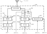
- FIG. 6 is a block diagram showing an example of the internal configuration of the first transmitting/receiving unit 160.
- the first transmitting/receiving unit 160 functions as a modulation/demodulation device.
- the first transmitting/receiving unit 160 includes a transmission/reception splitter 161, a demodulation device 162, a modulation device 164, a switch 166, and a detector 168.
- the demodulation device 162 includes a demodulator 1622 and a decoder 1624.
- the modulation device 164 includes an encoder 1642 and a modulator 1644.
- a carrier wave having a predetermined frequency (carrier frequency) is supplied to the modulator 1644 from a carrier wave generator (not shown).
- the transmission wave transmitted from the wireless power supply unit 200 is received as a received wave from the antenna via the transmission/reception splitter 161.
- the received wave is supplied to the input terminal 166a of the switch 166.
- a part of the received wave is also supplied to the detector 168.
- the detector 168 detects a certain amount (described later) from a part of the received wave and outputs a detection signal representing the amount.
- the detection signal is supplied to the switching control unit 119 (see FIG. 2) of the first CPU 110.
- the switching control unit 119 judges whether the received wave is the first received wave or the second received wave (described later) based on the detection signal, and outputs the judgment result as a switching control signal.
- the combination of the detector 168 and the switching control unit 119 serves as a judgment means for judging whether the received wave is the first received wave or the second received wave and outputting the judgment result as a switching control signal.
- the judgment means detector 168 and switching control unit 119
- the above judgment result is supplied to the switch 166.
- the switch 166 has an input terminal 166a, a first output terminal 166b, a second output terminal 166c, and a movable element 166d.
- the switch 166 is a change-over switch that switches the input terminal 166a to either the first output terminal 166b or the second output terminal 166c by the movable element 166d.
- the first output terminal 166b is connected to the electromagnetic wave power converter 170 (see FIG. 2).
- the second output terminal 166c is connected to the demodulation device 162.
- the switch 166 switches and outputs the received wave supplied to the input terminal 166a to the first output terminal 166b as a first received wave or to the second output terminal 166c as a second received wave. That is, the switch 166 acts as a switching means that switches the received wave to either the first received wave or the second received wave and outputs it based on the judgment result (switching control signal).
- the switch 166 switches the input terminal 166a to the first output terminal 166b by the movable element 166d. Therefore, the received wave supplied from the transmitting/receiving splitter 161 is supplied to the electromagnetic wave power converter 170 as the first received wave via the switch 166.
- the judgment result (switching control signal) indicates that the received wave is determined to be the second received wave. In this case, the switch 166 switches the input terminal 166a to the second output terminal 166c by the movable element 166d. Therefore, the received wave supplied from the transmitting/receiving splitter 161 is supplied to the demodulator 162 as the second received wave via the switch 166.
- the operation of the demodulator 162 will be described in detail later.
- the first CPU 110 of the wireless power receiving unit 100 includes a charging monitor 115 that monitors the charging of the secondary battery 130 as described above.
- the charging monitor 115 determines that the secondary battery 130 has been charged to a predetermined amount (for example, a full charge amount)
- the first CPU 110 controls the first transmitting/receiving unit 160 to transmit an information transmission signal including the wireless power stop request signal S stp to the wireless power supply unit 200.
- the predetermined amount can be set by initial settings, application settings, or the like.
- the first CPU 110 controls the first transmitting/receiving unit 160 to transmit the information transmission signal.
- the first transmitting/receiving unit 160 transmits a carrier wave carrying the information transmission signal to the wireless power supply unit 200 via an antenna.
- the modulation device 164 of the first transmission/reception unit 160 receives the wireless power supply permission signal S alw or the wireless power stop request signal S stp as data from the first CPU 110.
- the modulation device 164 modulates a carrier wave supplied from a carrier wave generator (not shown) with the data, and outputs a modulated wave. More specifically, the data is supplied to an encoder 1642 of the modulation device 164.
- the encoder 1642 encodes the data, and outputs a baseband signal. This baseband signal is supplied to a modulator 1644 of the modulation device 164.
- the modulator 1644 modulates a carrier wave supplied from the carrier wave generator with the baseband signal, and outputs a modulated wave.
- This modulated wave is transmitted as a transmission wave from the antenna to the wireless power supply unit 200 (FIG. 1) via the transmission/reception splitter 161. In this manner, the first transmission/reception unit 160 transmits the modulated wave as the transmission wave to the wireless power supply unit 200.
- the second transceiver 260 of the wireless power feeding unit 200 receives the transmission wave as the reception wave from the wireless power receiving unit 100.
- the second transceiver 260 demodulates the reception wave to restore an information transmission signal including the wireless power stop request signal S stp , and sends the restored wireless power stop request signal S stp to the third CPU 210.
- the third CPU 210 controls the second transceiver 260 to stop transmitting power from the first power supply unit 230 as an electromagnetic wave (first transmission wave).
- the second transceiver 260 receives the transmission wave carrying the information transmission signal including the wireless power stop request signal S stp transmitted from the wireless power receiving unit 100 as the received wave via the antenna and the transmission/reception splitter 261.
- the received wave is supplied to the demodulator 262.
- the demodulator 262 demodulates the received wave to restore the wireless power stop request signal S stp .
- the demodulator 2622 of the demodulator 262 demodulates the received wave to output a baseband signal.
- the baseband signal is supplied to the decoder 2624 of the demodulator 262.
- the decoder 2624 decodes the baseband signal to restore the wireless power stop request signal.
- the restored wireless power stop request signal S stp is supplied to the third CPU 210 (FIG. 4).
- the modulation device 264 modulates the second carrier having the second transmission power P T2 at a predetermined frequency (carrier frequency) supplied from the carrier generator 263 with data, and outputs a modulated wave.
- the encoder 2642 of the modulation device 264 encodes the data and outputs a baseband signal.
- the baseband signal is supplied to the modulator 2644 of the modulation device 262.
- the modulator 2644 modulates the second carrier with the baseband signal, and outputs a communication electromagnetic wave, which is a modulated wave.
- This communication electromagnetic wave (modulated wave) is transmitted from the antenna to the wireless power receiving unit 100 as a second transmission wave via the switch 266 and the transmission/reception splitter 261. In this way, the second transmission/reception unit 260 stops transmitting the first transmission wave. Instead, the second transmission/reception unit 260 transmits the second transmission wave.
- the first transceiver 160 receives the second transmission wave transmitted from the wireless power supply unit 200 as a second reception wave via the transmission/reception splitter 161. As described above, the wireless power receiving unit 100 needs to determine whether the reception wave is the first reception wave or the second reception wave. In this example, a portion of the second reception wave is supplied to the detector 168. The detector 168 detects a certain amount from a portion of the second reception wave and outputs a detection signal representing that amount. The detection signal is supplied to the switching control unit 119 (see FIG. 2) of the first CPU 110.
- the switching control unit 119 determines whether the reception wave is the first reception wave or the second reception wave based on the detection signal, and outputs the determination result as a switching control signal. In this example, since the received wave is the second received wave, the switching control unit 119 outputs a switching control signal indicating that the received wave is the second received wave.
- the switch 166 Since the judgment result (switching control signal) indicates that the received wave is the second received wave, the switch 166 switches the input terminal 166a to the second output terminal 166c by the movable element 166d. Therefore, the second received wave supplied from the transmitting/receiving splitter 161 is supplied to the demodulator 162 via the switch 166.
- the demodulator 162 demodulates the second received wave to restore the above data.
- the demodulator 1622 of the demodulator 162 demodulates the second received wave to output a baseband signal. This baseband signal is supplied to the decoder 1624 of the demodulator 162.
- the decoder 1624 decodes the baseband signal to restore the above data.
- the restored data is supplied to the first CPU 110 ( Figure 2).
- the wireless power receiving unit 100 when receiving a transmission wave from the wireless power supply unit 200 in which wireless power and information (data) are transmitted at different times using the same frequency (carrier frequency), can accurately determine whether the received wave is for power or communication, and can receive the received wave by dividing it into a first received wave and a second received wave.
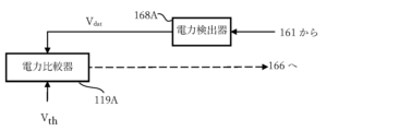
- Fig. 7 is a block diagram showing the determination means according to the first example.
- the first transmission power P T1 of the first transmission wave is greater than the second transmission power P T2 of the second transmission wave (P T1 >P T2 ). Therefore, the determination means according to the first example determines whether the received wave is the first received wave or the second received wave based on the magnitude of the received power P R of the received wave.
- the illustrated determination means includes a power detector 168A and a power comparator 119A.
- the power detector 168A functions as the detector 168 illustrated in Fig. 6.
- the power comparator 119A functions as the switching control unit 119 illustrated in Fig. 2.
- the power detector 168A receives a portion of the received wave output from the transmission/reception splitter 161.
- a predetermined threshold value Vth is also supplied to the power comparator 119A.
- This predetermined threshold value Vth is set to an approximately intermediate value between the power value VR1 of the first received power P R1 of the first received wave and the power value VR2 of the second received power P R2 of the second received wave (V R1 > Vth > V R2 ) .
- the power comparator 119A compares the detected power value Vdet of the power detection signal with the predetermined threshold value Vth and outputs a comparison result (determination result). In more detail, it is assumed that the detected power value Vdet is greater than the predetermined threshold value Vth .
- the power comparator 119A determines that the received wave is the first received wave and outputs a determination result indicating this as a switching control signal.
- the detected power value Vdet is smaller than the predetermined threshold value Vth .
- the power comparator 119A determines that the received wave is the second received wave and outputs a determination result indicating this as a switching control signal.
- the switching control signal is supplied to the switch 166 (FIG. 6) of the first transceiver unit 160 .
- the determination means according to the first example of such a configuration can accurately determine whether the received radio wave received by the wireless power receiving unit 100 is for power or communication.
- FIG. 8 is a block diagram showing the determination means according to the second example.
- the first transmission wave is composed of a first carrier wave (electromagnetic wave for power transmission) having a first transmission power P T1 at a predetermined frequency.
- the second transmission wave is composed of a modulated wave (electromagnetic wave for communication) obtained by modulating a second carrier wave having a second transmission power P T2 smaller than the first transmission power P T1 at a predetermined frequency with data. Therefore, the component strength of the predetermined frequency of the first transmission wave is stronger than the component strength of the predetermined frequency of the second transmission wave.
- the determination means determines whether the received wave is the first received wave or the second received wave based on the magnitude of the component strength of the predetermined frequency of the received wave.
- the illustrated determination means includes a frequency component extractor 168B and a frequency intensity comparator 119B.
- the frequency component extractor 168B functions as the detector 168 illustrated in Fig. 6.
- the frequency intensity comparator 119B functions as the switching control unit 119 illustrated in Fig. 2.
- the frequency component extractor 168B receives a portion of the received wave output from the transmitting/receiving branching filter 161.
- the frequency component extractor 168B extracts only a component having a predetermined frequency from the received wave, and outputs a frequency component signal indicating the extracted frequency component intensity I ext .
- This frequency component extraction signal is supplied to the frequency intensity comparator 119B.
- the frequency intensity comparator 119B is also supplied with a predetermined threshold Ith .
- This predetermined threshold Ith is set to an approximately intermediate value between the component intensity IR1 of the predetermined frequency of the first received wave and the component intensity IR2 of the predetermined frequency of the second received wave ( IR1 > Ith > IR2 ).
- the frequency intensity comparator 119B compares the extracted frequency component intensity Iext of the frequency component signal with the predetermined threshold Ith and outputs a comparison result (determination result). In more detail, it is assumed that the extracted frequency component intensity Iext is greater than the predetermined threshold Ith . In this case, the frequency intensity comparator 119B determines that the received wave is the first received wave and outputs a determination result indicating this as a switching control signal.
- the frequency intensity comparator 119B determines that the received wave is the second received wave and outputs a determination result indicating this as a switching control signal.
- the switching control signal is supplied to the switch 166 (FIG. 6) of the first transceiver unit 160 .
- the determination means according to the second example of this configuration can also accurately determine whether the received radio wave received by the wireless power receiving unit 100 is for power or communication.
- the wireless power receiving unit 100 is configured to be able to transmit the wireless power supply permission signal S alw or the wireless power stop request signal S stp to the wireless power supply unit 200. Then, the wireless power supply unit 200 transmits a first transmission wave to the wireless power receiving unit 100 in response to the wireless power supply permission signal S alw . Also, the wireless power supply unit 200 transmits a second transmission wave to the wireless power receiving unit 100 in response to the wireless power stop request signal S stp . That is, the wireless power supply permission signal S alw corresponds to the first transmission wave, and the wireless power stop request signal S stp corresponds to the second transmission wave.
- the determination means determines whether the received wave is the first received wave or the second received wave based on the wireless power supply permission signal S alw or the wireless power stop request signal S stp .
- the illustrated determination means is composed of a signal determiner 119C. This signal determiner 119C functions as the switching control unit 119 illustrated in Fig. 2. However, the illustrated determination means does not include a component corresponding to the detector 168 illustrated in Fig. 6.
- the signal determiner 119C is supplied with either the wireless power supply permission signal S alw or the wireless power stop request signal S stp at a certain timing. In response to the wireless power supply permission signal S alw , the signal determiner 119C determines that the received wave is the first received wave and outputs a determination result indicating that as a switching control signal. In addition, in response to the wireless power stop request signal S stp , the signal determiner 119C determines that the received wave is the second received wave and outputs a determination result indicating that as a switching control signal. The switching control signal is supplied to the switch 166 (FIG. 6) of the first transceiver 160.
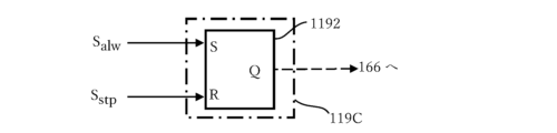
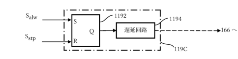
- Fig. 10 is a circuit diagram showing an example of the signal determiner 119C shown in Fig. 9.
- the illustrated signal determiner 119C is composed of an SR flip-flop 1192.
- the SR flip-flop 1192 has an input terminal S, an input terminal R, and an output terminal Q.
- a wireless power supply permission signal S_alw is supplied to the input terminal S.
- a wireless power stop request signal S_stp is supplied to the input terminal R.
- the output terminal Q outputs a switching control signal.
- FIG. 11 is a circuit diagram showing another example of the signal determiner 119C shown in FIG. 9.
- the illustrated signal determiner 119C is composed of an SR flip-flop 1192 and a delay circuit 1194.
- the output terminal Q of the SR flip-flop 1192 is connected to the input terminal of the delay circuit 1194.
- the above-mentioned time lag T L is set as the delay amount in the delay circuit 1194. Therefore, the delay circuit 1194 delays the decision result output from the output terminal Q of the SR flip-flop 1192 by the delay amount (time lag T L ) and outputs a switching control signal from its output terminal.
- the signal determiner 119C is not limited to a hardware circuit as shown in Figures 10 and 11, and may of course be realized by software.
- the timing at which the first CPU 110 generates the wireless power supply permission signal S alw or the wireless power stop request signal S stp is not limited to the above-mentioned case.
- the first CPU 110 generates the wireless power supply permission signal S alw when the comparison result indicates that the first access request is permitted.
- the first CPU 110 generates the wireless power stop request signal S stp when the comparison result indicates that the second access request is permitted or when it is determined that the secondary battery 130 has been charged to a predetermined amount.
- a lower limit VLL and an upper limit VUL are set for the remaining capacity (remaining amount) Vc of the secondary battery 130.
- Such lower limit VLL and upper limit VUL may be specified or set by a user, or may be set in advance.
- the first CPU 110 may generate the wireless power supply permission signal Salw when the remaining capacity Vc of the secondary battery 130 falls below the lower limit VLL (Vc ⁇ VLL ).
- the first CPU 110 may generate the wireless power stop request signal Sstp when the remaining capacity Vc of the secondary battery 130 exceeds the upper limit VUL (Vc> VUL ).
- the identification member 300 can be manufactured using well-known semiconductor manufacturing technology, but in the present invention, the identification member 300 is not limited to an integrated circuit made of semiconductors.
- the identification member 300 may be manufactured using an OEIC (Opto-Electronic Integrated Circuit) or a bio-based chip.
- the identification member 300 manufactured in this manner can be embedded in various objects as a small chip. Therefore, as an example of an object embedded as a small chip, an "R badge" such as that disclosed in Japanese Patent No. 4789092, which was invented by the inventors of the present application and has already been patented, may be used.
- the R badge is a general term for an identification member 300 embedded in an object that can be kept close to the owner, such as an ornament or clothing.
- the R badge may be, for example, an IC card with an IC (Integrated Circuit) chip embedded.
- the smartphone 100 has the above-mentioned trigger switch 101.
- the trigger switch 101 may be, for example, a power switch or a button on the touch panel 175.
- the owner of the smartphone 100 presses the trigger switch 101 to generate the above-mentioned trigger signal.
- the reception unit 111 (FIG. 2) of the first CPU 110 receives the trigger signal as an ON trigger signal, it instructs the first RFID interface unit 120 to start communication with the R badge 300.
- the subsequent matching operation is as described with reference to FIG. 2.
- matching data (first identification information and second identification information) is matched between the smartphone 100 and the R badge 300, and only when the matching result satisfies a predetermined condition, it is possible to allow the smartphone 100 to receive wireless power transmitted as electromagnetic waves from the wireless power supply unit 200.
- an IC chip embedded in something that is always worn or kept close by is collectively called an R badge.
- the IC chip stores the above-mentioned first identification information. Therefore, the IC chip corresponds to a combination of the second CPU 310 and the second matching data recording unit 350 shown in FIG. 2.
- the R badge incorporates an IC chip and a coil that operates as an antenna.
- the coil (antenna) functions as the second RFID interface unit 320 shown in FIG. 2.
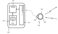
- FIG. 13 is a diagram showing a smartphone 100 and an R badge 300 with a built-in IC chip 360.
- the R badge 300 incorporates an IC chip 360 and an antenna (described below).
- An example of an R badge 300 with a built-in IC chip 360 is described below.
- FIG. 15 and 16 is a diagram showing an example of a second type R badge 300.
- the R badge 300 shown in Figure 15 is configured so that an IC chip 360 and an antenna 320 are built into a main body 610 such as a tie pin.
- the R badge 300 shown in Figure 16 is configured so that an IC chip 360 and an antenna 320 are built into a main body 620 such as a cufflink, badge, brooch, pendant, contact lens, etc.
- the second type R badge 300 is a type of R badge in which an IC chip 360 and an antenna 320 are built into something that is worn.
- Each of Figures 17 and 18 shows an example of a third type of R badge 300.
- the R badge 300 shown in Figure 17 is configured so that an IC chip 360 and an antenna 320 are built into a main body 630 such as a wallet, a pass case, etc.
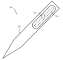
- the R badge 300 shown in Figure 18 is configured so that an IC chip 360 and an antenna 320 are built into a main body 640 such as a writing implement, a lighter, etc.
- the third type of R badge 300 is a type of R badge in which an IC chip 360 and an antenna 320 are built into something that is kept close by.
- IC chips 360 can be embedded in a variety of things, and antennas 320 come in a variety of shapes.
- IC chip 360 which is a recording element, includes a communication control IC 362, a control unit 364 consisting of a CPU and the like, and memory 366.
- IC chip 360 transmits and receives data via antenna 320.
- Memory 366 is connected to control unit 364, and includes a data storage area for storing data and a software storage area for storing software for controlling communication control IC 362.
- Memory 366 may further include an OS storage area for storing an operating system (OS).
- OS operating system
- the wireless power receiving unit 100 in consideration of the case where multiple third party R badges are present in the vicinity of the wireless power receiving unit 100 (smartphone 100), it is desirable to make it so that the first identification information ID1 cannot be read unless the wireless power receiving unit 100 (smartphone 100) and the R badge 300 are in close proximity to each other.
- close proximity means that transmission and reception is possible between the wireless power receiving unit 100 (smartphone 100) being used and the R badge 300 worn by the user, such as on clothing.
- the R badge 300 it is preferable for the R badge 300 to use (have built-in) a proximity or contact type IC chip 360. Furthermore, it is preferable that the range in which transmission and reception is possible between the R badge 300 and the wireless power receiving unit 100 (smartphone 100) is a few centimeters or less.
- the smartphone 100 is set to a registration mode for registering the first identification information ID1 of the R badge 300 as the second identification information ID2.
- a PIN number or biometrics iris, voiceprint, fingerprint, etc.
- a command to start reading is sent from the control unit 364 to the communication control IC 362, which then sends a transmission request (such as a power pulse) from the antenna 320 to start reading the R badge 300.
- a predetermined time t is set in the timer of the smartphone 100. Then, until the time t has elapsed, it is repeatedly checked whether the first identification information ID1 has been received from the R badge 300.
- an error message is displayed on the screen of the smartphone 100.
- the received first identification information ID1 is identification information that has already been registered, an error message is displayed on the screen of the smartphone 100.
- the first identification information ID1 is stored as second identification information ID2 in the first matching data recording unit 150 (see Figure 2) of the smartphone 100 and registered.
- the same identification information as the first identification information ID1 stored in the R badge 300 can be registered as the second identification information ID2 in the smartphone 100.
- the identification member 300 is not limited to the R badge.
- the identification member 300 may be a privileged card that can be transmitted and received via the RFID interface.
- privileged cards examples include My Number cards, driver's licenses, and passports. Such privileged cards have information recorded on them that identifies the holder as a physically disabled person or elderly person (65 years of age or older).
- the wireless power receiving unit 100 may incorporate a known GPS (global positioning system) function, such as that incorporated in a known smartphone.
- the wireless power receiving unit 100 includes a GPS receiver 180 that receives radio waves from at least four GPS satellites.
- the first CPU 110 includes a location information acquisition unit 116 that acquires location information on the location of the wireless power receiving unit 100 based on a signal received by the GPS receiver 180.
- the access control unit 113 when the access control unit 113 obtains the comparison result that the first access request is permitted, the first CPU 110 of the wireless power receiving unit 100 controls the first transceiver unit 160 to transmit, to the wireless power supply unit 200, an information transmission signal including not only the wireless power supply permission signal S alw but also location information.
- the second transceiver 260 of the wireless power supply unit 200 receives an information transmission signal including the wireless power supply permission signal S alw and the position information.
- the second transceiver 260 sends the received information transmission signal including the wireless power supply permission signal S alw and the position information to the third CPU 210.
- the third CPU 210 controls the second transceiver 260 to transmit power from the first power supply unit 230 as electromagnetic waves toward the wireless power receiving unit 100 whose position is specified by the position information.
- various methods can be used to transmit electromagnetic waves toward the wireless power receiving unit 100 whose position is specified by the position information.
- a directional antenna is used as the antenna provided in the wireless power supply unit 200.
- the directional antenna can be controlled so as to be directed toward the wireless power receiving unit 100 whose position is specified by the position information.
- the wireless power supply unit 200 may transmit electromagnetic waves so as to generate an energy pocket around the wireless power receiving unit 100 whose position is specified by the position information.
- various electromagnetic energies are radiated into the air.
- radio waves for receiving broadcasts are present in the environment. Therefore, in the wireless power receiving unit 100, a part of this electromagnetic energy (radio waves for receiving broadcasts) present in the surroundings may be received by the first transceiver 160, converted into DC power by the electromagnetic wave power converter 170, and the converted DC power may be charged into the secondary battery 130 by the charging unit 132.
- the "received electromagnetic energy" at this time is extremely small compared to the wireless power transmitted from the wireless power supply unit 200.
- the wireless power receiving unit 100 may be configured to be able to set the charging mode using a mode setting screen of the display unit 140.
- the wireless power receiving unit 100 may be configured to set the charging mode by the operator using (operating) an application downloaded and installed in advance.
- the "charging mode" may be, for example, a full charge mode in which the secondary battery 130 is charged until it is fully charged, a predetermined amount mode in which the secondary battery 130 is charged by a predetermined amount, or a power supply linked mode in which the secondary battery 130 is charged only while the wireless power receiving unit 100 is in use in conjunction with the on/off of the power switch.
- the "charging mode” may be a time setting mode in which the secondary battery 130 is charged for a predetermined time, for example, specified by operating the numeric keypad.
- the operator of the wireless power receiving unit 100 can operate the application to set the "charging mode” on the mode setting screen of the display unit 140. Therefore, the application serves as a charging mode setting means for setting the charging mode.
- the charging monitor 115 (FIG. 2) monitors the charging of the secondary battery 130 according to the set charging mode. For example, if the charging mode is set to the full charge mode, the charging monitor 115 monitors (determines) whether the secondary battery 130 is fully charged. If the charging mode is set to the predetermined amount mode, the charging monitor 115 monitors (determines) whether the secondary battery 130 is charged to a predetermined amount. If the charging mode is set to the power supply linked mode, the charging monitor 115 monitors (determines) whether the wireless power receiving unit 100 is in use in conjunction with the on/off of the power switch.
- the charging monitor 115 starts a timer from the time when charging of the secondary battery 130 is started, measures the time, and determines whether the measured time of the timer reaches a predetermined time.
- the first CPU 110 of the wireless power receiving unit 100 controls the first transmitting/receiving unit 160 to transmit an information transmission signal including a wireless power stop request signal S stp to the wireless power feeding unit 200.
- the first transmitting/receiving unit 160 transmits a modulated wave carrying the information transmission signal to the wireless power feeding unit 200 via the antenna.
- the wireless power supply unit 200 may be a base station.
- the third modified example is a billing system using the wireless power transmission system 10 according to the first embodiment shown in FIG.
- FIG. 21 is a schematic diagram showing the schematic configuration of a billing system 20 according to the third modified example.
- the illustrated billing system 20 includes a wireless power receiving unit 100, a base station 200, and an identification member 300, similar to the wireless power transmission system 10 shown in FIG. 1.
- the billing system 20 further includes a management server 700 and a financial institution 800.
- the financial institution 800 is a financial institution such as a bank terminal or an online bank. Note that, instead of the financial institution 800, when making a payment using electronic money or various points operated by a business company, payment processing may be performed in real time using an application.
- the base station 200 and the management server 700 are connected via a communication line 900.
- a financial institution 800 is also connected to the communication line 900.
- the communication line 900 may include the Internet.
- the wireless power supply unit 200 itself controls the transmission and suspension of wireless power.
- the management server 700 controls the transmission and suspension of wireless power from the base station 200 via the communication line 900.
- the base station 200 transmits the information transmission signal including the received wireless power supply permission signal S alw or wireless power stop request signal S stp as is to the management server 700 via the communication line 900 .
- the management server 700 transmits a permission command to the base station 200 via the communication line 900.
- the third CPU 210 of the base station 200 controls the second transceiver unit 260 to transmit power from the first power supply unit 230 as electromagnetic waves.
- the management server 700 transmits a stop command to the base station 200 via the communication line 900.
- the third CPU 210 of the base station 200 controls the second transceiver unit 260 so as to stop transmitting the power from the first power supply unit 230 as electromagnetic waves.
- the wireless power receiving unit 100 has a charge amount measuring unit 114 that measures the charge amount charged to the secondary battery 130 by the charging unit 132.
- the wireless power receiving unit 100 is assigned a registration number that identifies the owner of the wireless power receiving unit 100. This registration number may be the same as the second identification information ID2 described above, or may be different. If they are different, the registration number is linked to the second identification information ID2.
- the first CPU 110 of the wireless power receiving unit 100 controls the first transmission/reception unit 160 to transmit an information transmission signal including this registration number and the charge amount measured by the charge amount measuring unit 114.
- the measured charge amount is the charge amount charged to the secondary battery 130 during the period from the time when the wireless power supply permission signal S alw is transmitted to the time when the wireless power stop request signal S stp is transmitted.
- the first transmission/reception unit 160 transmits a modulated wave carrying the information transmission signal to the base station 200 via an antenna.
- the base station 200 receives the modulated wave as a received wave, demodulates the received wave to restore an information transmission signal including the registration number and the measured charge amount, and transmits the restored information transmission signal to the management server 700 via the communication line 900.
- the registration number is the same as the second identification information ID2 described above, and the identification member 300 is the privileged card.
- the owner of the wireless power receiving unit 100 is identified as a physically disabled person or an elderly person by the privileged card.
- the first CPU 110 of the wireless power receiving unit 100 controls the first transceiver 160 so as not to transmit the information transmission signal including the registration number and the amount of charge described above. Therefore, the base station 200 does not transmit the information transmission signal to the management server 700 via the communication line 900.
- no charge (collection) for power (electricity charges) is performed, as described below.
- FIG. 22 is a block diagram showing an example of the configuration of the management server 700.
- the management server 700 includes a fourth CPU 710, a second power supply unit 730, a power consumption management table 750, and a third transmission/reception unit 760.
- the fourth CPU 710 includes an addition unit 712 and an electricity fee calculation unit 714.
- the third transceiver 760 receives an information transmission signal including the registration number and the measured charge amount from the base station 200 via the communication line 900.
- FIG. 23 shows an example of a power consumption management table 750.
- the power consumption management table 750 is a table that accumulates (manages) the power consumption of the wireless power receiving unit 100 for each owner (i.e., each registration number) for each specified period (e.g., every month).
- the addition unit 712 adds the measured charging amount to the amount of power consumption recorded in the power consumption management table 750 for each registration number, and registers the added amount of power consumption in the power consumption management table 750, thereby updating the amount of power consumption.
- the electricity fee calculation unit 714 refers to the power consumption management table 750 and calculates the electricity fee by multiplying the amount of power consumption recorded for each registration number by a predetermined coefficient. Note that when the electricity fee calculation unit 714 finishes calculating the electricity fee, the "not yet collected” flag remains set. Then, after the electricity fee is actually collected, the flag is set to "collected", and the amount of power consumption registered in the power consumption management table 750 is reset to zero.
- the fourth CPU 710 transmits fee data including the registration number and the calculated electricity fee to the financial institution 800 via the communication line 900.
- the financial institution 800 Based on the received fee data, the financial institution 800 automatically withdraws the electricity fee from the account linked to the owner of the wireless power receiving unit 100 (i.e., the above registration number) and automatically transfers it to the account of the administrator who manages the management server 700.
- the administrator may send an invoice by mail or the like to the owner of the above registration number, with the electricity fee written on it and instructions to transfer it to the administrator's account.
- payment processing may be performed in real time using an application.
- the administrator of the management server 700 can bill (collect) owners of the wireless power receiving units 100 other than the physically disabled or elderly for the power (electricity charges) consumed by the wireless power receiving units 100.
- Second Embodiment 24 is a schematic diagram showing a schematic configuration of a wireless power transmission system 10A according to a second embodiment of the present disclosure.
- the illustrated wireless power transmission system 10A includes a wireless power receiving unit 100A, a wireless power supply unit 200, and an identification member 300A.
- the illustrated wireless power transmission system 10A is also a system that selectively transmits wireless power from the wireless power supply unit 200 to the wireless power receiving unit 100A by electromagnetic waves (first transmission waves).
- an identification member 300A is used, as described later.
- the wireless power receiving unit 100A when the wireless power receiving unit 100A is identified by the identification member 300A, the wireless power receiving unit 100A transmits an information transmission signal including a wireless power supply permission signal S alw or a wireless power stop request signal S stp to the wireless power receiving unit 200, as described later.
- the wireless power feeding unit 200 transmits wireless power to the wireless power receiving unit 100A by electromagnetic waves.
- the wireless power receiving unit 100A receives the wireless power and charges a secondary battery (battery) described later.
- the wireless power feeding unit 200 stops transmitting wireless power to the wireless power receiving unit 100A by electromagnetic waves (first transmission waves).
- the wireless power receiving unit 100A determines that the secondary battery (battery) has been charged with a predetermined amount of power (for example, a fully charged amount)
- the wireless power receiving unit 100A also transmits an information transmission signal including the wireless power stop request signal S stp to the wireless power feeding unit 200.
- the wireless power feeding unit 200 stops transmitting wireless power by electromagnetic waves to the wireless power receiving unit 100A.
- the wireless power transmission system 10A according to the thirty-second embodiment makes it possible to selectively transmit wireless power only to a specific wireless power receiving unit 100A.
- the wireless power supply unit 200 may be fixed or movable.
- the wireless power supply unit 200 may be composed of a base station, for example, as described below.
- the wireless power supply unit 200 transmits not only wireless power but also information (data) by electromagnetic waves.
- the electromagnetic waves may be, for example, microwaves.
- the base station is not limited to a fixed base station, and may be a mobile base station.
- the power transmission device 200 may be a low earth orbit satellite (LEO: Low Earth Orbit).
- the wireless power receiving unit 100A has a secondary battery, as described below.
- the wireless power receiving unit 100A is configured to be able to charge the secondary battery by receiving wireless power from the wireless power supply unit 200 via electromagnetic waves.
- the wireless power receiving unit 100A may be composed of a mobile terminal such as a smartphone, a mobile phone, a PDA (personal digital assistant), a laptop, or a personal computer.
- the wireless power receiving unit 100A is not limited to these mobile terminals, and is used by being built into a battery-driven electronic device equipped with a secondary battery (capacitor) for operation.
- the battery-driven electronic device is not limited to a mobile device, and may be fixed.
- the size of the secondary battery mounted inside the battery-driven electronic device is also not particularly limited. For example, in mountainous areas or places on the ocean, it may be impossible to lay a power transmission line.
- the wireless power transmission system 10A can supply power to a battery-driven electronic device installed in a place where such a power transmission line cannot be laid.
- the battery-driven electronic device may be, for example, a drone, an IoT (Internet of Things) device, an electric vehicle, or the like.
- IoT Internet of Things
- electric vehicle or the like.
- LEO low earth orbit satellite
- FIG. 25 is a block diagram showing an example of the internal configuration of the wireless power receiving unit 100A and the identification member 300A used in the wireless power transmission system 10A shown in FIG. 24.
- the illustrated wireless power receiving unit 100A is a smartphone.
- the wireless power receiving unit 100A has a camera 120A instead of the first RFID interface section (I/F) 120, and has the same configuration and operates in the same manner as the wireless power receiving unit 100 shown in FIG. 2, except that the operation of the first CPU differs as described below. Therefore, the first CPU is given the reference symbol 110A.
- the wireless power receiving unit 100A components that have the same configuration and operate in the same manner as the wireless power receiving unit 100 shown in FIG. 2 are given the same reference symbols, and their description will be omitted to simplify the description.
- the illustrated wireless power receiving unit 100A is a smartphone. It should be noted that commercially available, well-known smartphones already have hardware elements other than the electromagnetic wave power converter 170. In other words, the illustrated wireless power receiving unit 100A is configured by further incorporating an electromagnetic wave power converter 170 in a commercially available smartphone.
- the electromagnetic wave power converter 170 for example, a rectifier circuit such as that described in the above-mentioned non-patent document 3 can be used.
- the identification member 300A includes a second matching data recording section 350A.
- the second matching data recording section 350A will be described in detail later.
- the wireless power receiving unit 100A and the identification member 300A are configured to enable the camera 120A to capture an image of the matching data recorded in the second matching data recording unit 350A.
- the first matching data recording unit 150 and the second matching data recording unit 350A each record matching data for matching the wireless power receiving unit 100B and the identification member 300A.
- the matching data recorded in the second matching data recording unit 350A is called "first identification information”
- the matching data recorded in the first matching data recording unit 150 is called "second identification information”.
- the first identification information is information assigned so as to uniquely identify the identification member 300A.
- the first identification information is information that can uniquely identify the user (owner) of the wireless power receiving unit 100A.
- the first identification information may be written to be unique when the identification member 300A is manufactured.
- the second identification information is information that is registered in advance in the wireless power receiving unit 100A, as described below, and is the same information as the first identification information. Therefore, the identification member 300A and the wireless power receiving unit 100A owned by the same owner are assigned the same identification information, the first identification information and the second identification information, respectively.
- the reception unit 111 of the first CPU 110A receives a trigger signal generated by pressing a trigger switch 101 (described later) of the wireless power receiving unit 100A.
- the trigger switch 101 is the shutter button of the camera 120A.
- the reception unit 111 receives the trigger signal as an on-trigger signal, which is a first access request to receive wireless power from the wireless power supply unit 200.
- camera 120A In response to the trigger signal, camera 120A captures the first identification information from identification member 300A.
- camera 120A functions as a reader that reads the first identification information from identification member 300A in response to the trigger signal.
- the comparison unit 112 compares the read first identification information with the second identification information previously recorded in the first matching data recording unit 150.
- the first CPU 110A includes an access control unit 113, a charge amount measurement unit 114, and a charge monitoring unit 115.
- the access control unit 113 permits or prohibits the first access request received by the reception unit 111 according to the comparison result by the comparison unit 112.
- the first CPU 110A controls the first transmission/reception unit 160 to transmit an information transmission signal including the wireless power supply permission signal S alw toward the wireless power supply unit 200.
- the first transmission/reception unit 160 modulates a carrier wave with the information transmission signal and transmits the modulated wave toward the wireless power supply receiving unit 200 via an antenna. Therefore, the first transceiver 160 functions as a transmitter that transmits an information transmission signal including the wireless power supply permission signal S alw to the wireless power supply unit 200. After transmitting this information transmission signal, the charge amount measuring unit 114 measures the amount of charge charged to the secondary battery 130 by the charging unit 132. The charge monitoring unit 115 monitors the charging of the secondary battery 130 as described above.
- the wireless power supply unit 200 shown in FIG. 24 has the same configuration and operates in the same manner as the wireless power supply unit 200 shown in FIG. 4. That is, the wireless power supply unit 200 includes a third CPU 210, a first power supply unit 230, and a second transceiver unit 260.
- the second transmitting/receiving unit 260 receives the modulated wave from the wireless power receiving unit 100A as a received wave, and demodulates the received wave to restore an information transmission signal including the wireless power supply permission signal S alw .
- the restored information transmission signal including the wireless power supply permission signal S alw is sent to the third CPU 210.
- the third CPU 210 controls the second transmitting/receiving unit 260 to transmit power from the first power supply unit 230 as an electromagnetic wave to the wireless power receiving unit 100B. Therefore, the second transmitting/receiving unit 260 functions as a power transmitting unit that transmits power to the wireless power receiving unit 100A as an electromagnetic wave (first transmission wave).
- the electromagnetic waves (first transmission waves) transmitted from the wireless power supply unit 200 are received as the first reception waves by the first transmission/reception section 160 of the wireless power receiving unit 100A, and are sent to the electromagnetic wave power converter 170 as described above.
- the electromagnetic wave power converter 170 converts the first reception waves into DC power.
- the converted DC power is sent to the charging section 132.
- the charging section 132 charges the secondary battery 130 with the DC power.
- the first CPU 110A of the wireless power receiving unit 100A includes a charging monitor 115 that monitors the charging of the secondary battery 130.
- the charging monitor 115 determines that the secondary battery 130 has been charged to a predetermined amount (for example, a full charge amount)
- the first CPU 110A controls the first transmitting/receiving unit 160 to transmit an information transmission signal including a wireless power stop request signal S stp to the wireless power supply unit 200.
- the predetermined amount can be set by initial settings or application settings.
- the first CPU 110A controls the first transmitting/receiving unit 160 to transmit the information transmission signal.
- the first transmitting/receiving unit 160 modulates a carrier wave with the information transmission signal and transmits the modulated wave to the wireless power supply unit 200 via an antenna.
- the second transceiver 260 of the wireless power supply unit 200 receives the modulated wave from the wireless power receiving unit 100A as a received wave, demodulates the received wave, and restores an information transmission signal including the wireless power stop request signal S stp .
- This restored information transmission signal including the wireless power stop request signal S stp is sent to the third CPU 210.
- the third CPU 210 controls the second transceiver 260 to stop transmitting power from the first power supply unit 230 as an electromagnetic wave.
- the reception unit 111 of the first CPU 110A receives a trigger signal generated by pressing the trigger switch 101 of the wireless power receiving unit 100A.
- the reception unit 111 receives the trigger signal as an off-trigger signal, which is a second access request for stopping the supply of wireless power from the wireless power supply unit 200.
- the access control unit 113 obtains a comparison result that the second access request is permitted, the first CPU 110A controls the first transmission/reception unit 160 to transmit an information transmission signal including the wireless power stop request signal S stp toward the wireless power supply unit 200.
- the first transmission/reception unit 160 modulates a carrier wave with the information transmission signal and transmits the modulated wave toward the wireless power supply unit 200 via the antenna. Therefore, the first transceiver 160 functions as a transmitter that transmits an information transmission signal including the wireless power stop request signal S stp to the wireless power feeding unit 200 .
- the identification member 300A is made of a recording medium on whose surface a "two-dimensional code" is printed or displayed as the above-mentioned first identification information.
- a two-dimensional code is a code that has information in two directions, i.e., horizontally and vertically.
- the two-dimensional code may be a QR code (registered trademark), a micro QR code, a SP code (registered trademark), an AztecCode, a DataMatrix, a PDF417, a MaxiCode, a VeriCode, or the like.
- a QR code is used as the two-dimensional code.
- a two-dimensional code can encode more information than a one-dimensional code such as a barcode, which has information only in the horizontal direction.
- FIG. 26 is a diagram showing an example in which the wireless power receiving unit 100A is realized in the form of a smartphone, and the identification member 300A is realized in the form of a recording medium.
- the smartphone 100A has a trigger switch 101.
- the trigger switch 101 is made of the shutter button of the camera 120A.
- the owner of the smartphone 100A presses the trigger switch 101 (the shutter button of the camera 120A) to generate the above-mentioned trigger signal.
- the reception unit 111 (FIG. 25) of the first CPU 110A receives the trigger signal as an ON trigger signal, it instructs the camera 120A to capture a two-dimensional code from the recording medium 300A.
- the comparison operation thereafter is as described with reference to FIG. 25.
- matching data (first identification information and second identification information) is matched between smartphone 100A and recording medium 300A, and only when the matching result satisfies a predetermined condition, it is possible to allow smartphone 100A to receive wireless power transmitted as electromagnetic waves (first transmission waves) from wireless power supply unit 200.
- FIG. 27 is a diagram showing an example of a recording medium 300A in which a "two-dimensional code" is printed on a card or the like as an identification member 300A.
- a QR code registered trademark
- FIG. 27 has a QR code printed on a card or the like, a QR code displayed on a display screen may also be used.
- the smartphone 100A is set to a registration mode for registering the first identification information ID1 of the recording medium 300A as the second identification information ID2.
- a PIN number or biometrics iris, voiceprint, fingerprint, etc.
- a command to start reading is sent from the first CPU 110A to the camera 120A, and reading of the recording medium 300A begins.
- a predetermined time t is set in the timer of the smartphone 100A. Then, until the time t has elapsed, it is repeatedly checked whether the first identification information ID1 has been read from the recording medium 300A.
- an error message is displayed on the screen of the smartphone 100A.
- an error message is displayed on the screen of the smartphone 100A.
- the first identification information ID1 is stored as the second identification information ID2 in the first matching data recording unit 150 (see FIG. 25) of the smartphone 100A and registered.
- the same identification information as the first identification information ID1 registered in the recording medium 300A can be registered as the second identification information ID2 in the smartphone 100A.
- the identification member 300A is not limited to a recording medium on which the above-mentioned two-dimensional code is recorded.
- the identification member 300A may be a card with the above-mentioned privileges that can be photographed by the camera 120A.
- cards with privileges include a My Number card, a driver's license, a passport, and a health insurance card.
- Such cards with privileges have information recorded thereon (e.g., date of birth, etc.) that can identify the holder as a physically disabled person or elderly person (person 65 years of age or older).
- the wireless power supply unit 200 may be a base station.
- the fourth modified example is a billing system using the wireless power transmission system 10A according to the second embodiment shown in FIG.
- FIG. 28 is a schematic diagram showing the schematic configuration of a billing system 20A according to this fourth modified example.
- the illustrated billing system 20A includes a wireless power receiving unit 100A, a base station 200, and an identification member 300A, similar to the wireless power transmission system 10A shown in FIG. 24.
- the billing system 20A further includes a management server 700 and a financial institution 800.
- the financial institution 800 is a financial institution such as a bank terminal or an online bank. Note that, instead of the financial institution 800, when making a payment using electronic money or various points operated by a business company, a payment process may be performed in real time using an application.
- the base station 200 and the management server 700 are connected via a communication line 900.
- a financial institution 800 is also connected to the communication line 900.
- the communication line 900 may include the Internet.
- the wireless power supply unit 200 itself controls the transmission and stopping of wireless power.
- the management server 700 controls the transmission and stopping of wireless power from the base station 200 via the communication line 900.
- the base station 200 transmits the information transmission signal including the received wireless power supply permission signal S alw or wireless power stop request signal S stp as is to the management server 700 via the communication line 900 .
- the management server 700 transmits a permission command to the base station 200 via the communication line 900.
- the third CPU 210 of the base station 200 controls the second transceiver unit 260 to transmit power from the first power supply unit 230 as electromagnetic waves (first transmission waves).
- the management server 700 transmits a stop command to the base station 200 via the communication line 900.
- the third CPU 210 of the base station 200 controls the second transceiver unit 260 so as to stop transmitting the power from the first power supply unit 230 as an electromagnetic wave (first transmission wave).
- the wireless power receiving unit 100A has a charge amount measuring unit 114 that measures the amount of charge charged to the secondary battery 130 by the charging unit 132.
- the wireless power receiving unit 100A is assigned a registration number that identifies the owner of the wireless power receiving unit 100A. This registration number may be the same as the second identification information ID2 described above, or may be different. If different, the registration number is linked to the second identification information ID2.
- the first CPU 110A of the wireless power receiving unit 100A controls the first transmission/reception unit 160 to transmit an information transmission signal including the registration number and the charge amount measured by the charge amount measuring unit 114.
- the first transmission/reception unit 160 modulates a carrier wave with the information transmission signal and transmits the modulated wave to the base station 200 via an antenna.
- the charge amount measured by the charge amount measurement unit 114 is the charge amount charged in the secondary battery 130 during the period from the time when the wireless power supply permission signal S_alw is transmitted to the time when the wireless power stop request signal S_stp is transmitted.
- the base station 200 receives the modulated wave as a received wave, demodulates the received wave to restore an information transmission signal including the registration number and the measured charge amount, and transmits the restored information transmission signal to the management server 700 via the communication line 900.
- the registration number is the same as the second identification information ID2 described above, and the identification member 300A is the privileged card described above.
- the owner of the wireless power receiving unit 100A is identified as a physically disabled person or an elderly person by the privileged card.
- the first CPU 110A of the wireless power receiving unit 100A controls the first transceiver 160 so as not to transmit the information transmission signal including the registration number and the measured charge amount. Therefore, the base station 200 does not transmit the information transmission signal to the management server 700 via the communication line 900.
- no charge (collection) for power (electricity charges) is performed, as described below.
- the management server 700 has a configuration and operates similarly to that shown in FIG. 22. Therefore, to simplify the explanation, further explanation will be omitted.
- the administrator of the management server 700 can bill (collect) owners of the wireless power receiving unit 100A other than the physically disabled or elderly for the power (electricity charges) consumed by the wireless power receiving unit 100A.
- the identification members 300 and 300A are respectively recorded with an R badge and a recording medium.
- the information recorded in the identification members 300 and 300A is used as the first identification information ID1.
- the first identification information ID1 may be any information that can uniquely identify the user (owner) of the wireless power receiving unit 100 or 100A. Therefore, the first identification information ID1 may be biometric information of the user (owner) himself, which is well known in the technical field of biometric authentication, without using the identification members 300 and 300A. Examples of biometric information used for such biometric authentication include fingerprints, veins, irises, faces, voices, auricles, and behaviors.
- the wireless power receiving units 100 and 100A may be provided with a biometric authentication sensor (described later) or a camera capable of reading such biometric information as a reading unit for reading the first identification information. Furthermore, such biometric authentication sensors are well known in the field of biometric authentication, so their description will be omitted.
- the same information as the biometric information is pre-registered as the second identification information ID2 in the first matching data recording section 150 of the wireless power receiving units 100 and 100A.
- the method of pre-registering such second identification information ID2 in the wireless power receiving units 100 and 100A is well known in the technical field of biometric authentication, so a description thereof will be omitted.
- Third Embodiment 29 is a schematic diagram showing a schematic configuration of a wireless power transmission system 10B according to a third embodiment of the present disclosure.
- the illustrated wireless power transmission system 10B includes a wireless power receiving unit 100D100B and a wireless power supply unit 200.
- the illustrated wireless power transmission system 10B is also a system that selectively transmits wireless power from the wireless power supply unit 200 to the wireless power receiving unit 100B by electromagnetic waves.
- the third embodiment uses the biometric authentication technology described above.
- the wireless power receiving unit 100B when the wireless power receiving unit 100B is identified (authenticated) by biometric authentication, the wireless power receiving unit 100B transmits an information transmission signal including a wireless power supply permission signal S alw or a wireless power stop request signal S stp to the wireless power receiving unit 200.
- the wireless power feeding unit 200 transmits wireless power to the wireless power receiving unit 100B by electromagnetic waves (first transmission waves).
- the wireless power receiving unit 100B receives the wireless power and charges a secondary battery (battery) described below.
- the wireless power feeding unit 200 stops transmitting wireless power to the wireless power receiving unit 100B by electromagnetic waves (first transmission waves).
- the wireless power receiving unit 100B determines that the secondary battery (battery) has been charged with a predetermined amount of power (for example, a fully charged amount)
- the wireless power receiving unit 100B also transmits an information transmission signal including the wireless power stop request signal S stp to the wireless power feeding unit 200.
- the predetermined amount can be set by initial settings, application settings, etc.
- the wireless power feeding unit 200 stops transmitting wireless power to the wireless power receiving unit 100B by electromagnetic waves (first transmission waves).
- the wireless power transmission system 10B according to the third embodiment makes it possible to selectively transmit wireless power only to a specific wireless power receiving unit 100B.
- the wireless power supply unit 200 may be fixed or movable.
- the wireless power supply unit 200 may be composed of a base station, for example, as described below.
- the wireless power supply unit 200 transmits not only wireless power but also information (data) by electromagnetic waves.
- the electromagnetic waves may be, for example, microwaves.
- the base station is not limited to a fixed base station, and may be a mobile base station.
- the power transmission device 200 may be a low earth orbit satellite (LEO: Low Earth Orbit).
- the wireless power receiving unit 100B has a secondary battery, as described below.
- the wireless power receiving unit 100B is configured to be able to charge the secondary battery by receiving wireless power from the wireless power supply unit 200 via electromagnetic waves (first transmission waves).
- the wireless power receiving unit 100B may be composed of a mobile terminal such as a smartphone, a mobile phone, a PDA (personal digital assistant), a laptop, or a personal computer.
- the wireless power receiving unit 100B is not limited to these mobile terminals, but is used by being built into a battery-driven electronic device equipped with a secondary battery (capacitor) for operation.
- the battery-driven electronic device is not limited to a mobile device, but may be fixed.
- the size of the secondary battery mounted inside the battery-driven electronic device is also not particularly limited. For example, in mountainous areas or places on the ocean, it may be impossible to lay a power transmission line.
- the wireless power transmission system 10B can supply power to a battery-driven electronic device installed in a place where such a power transmission line cannot be laid.
- the battery-driven electronic device may be, for example, a drone, an IoT (Internet of Things) device, an electric vehicle, or the like.
- IoT Internet of Things
- electric vehicle or the like.
- LEO low earth orbit satellite
- FIG. 30 is a block diagram showing an example of the internal configuration of a wireless power receiving unit 100B used in the wireless power transmission system 10B shown in FIG. 29.
- the illustrated wireless power receiving unit 100B is a smartphone.
- the wireless power receiving unit 100B has a camera 120A and the biometric authentication sensor 120B instead of the first RFID interface unit (I/F) 120, and has the same configuration and operates as the wireless power receiving unit 100 shown in FIG. 2, except for the difference in the operation of the first CPU as described below. Therefore, the first CPU is given the reference symbol 110B.
- the wireless power receiving unit 100B the components that have the same configuration and operate as the wireless power receiving unit 100 shown in FIG. 2 are given the same reference symbols, and their description will be omitted to simplify the description.
- the biometric authentication is fingerprint authentication
- the biometric authentication sensor 120B may be composed of a fingerprint sensor.
- the camera 120A is used for biometric authentication.
- the illustrated wireless power receiving unit 100B is a smartphone. It should be noted that commercially available, well-known smartphones already have hardware elements other than the electromagnetic wave power converter 170. In other words, the illustrated wireless power receiving unit 100B is configured by further incorporating an electromagnetic wave power converter 170 in a commercially available smartphone.
- the electromagnetic wave power converter 170 for example, a rectifier circuit such as that described in the above-mentioned non-patent document 3 can be used.
- the wireless power receiving unit 100B is configured to be able to read the biometric information of the user (owner) of the wireless power receiving unit 100B as matching data using a camera 120A or a biometric authentication sensor 120B.
- the first matching data recording unit 150 records matching data for matching the wireless power receiving unit 100B and the user (owner).
- the matching data which is the biometric information of the user (owner)
- the matching data recorded in the first matching data recording unit 150 is called “second identification information.”
- the first identification information which is biometric information, is information that can uniquely identify the user (owner) of the wireless power receiving unit 100B.
- the second identification information is information that is registered in advance in the wireless power receiving unit 100B, and is the same information as the first identification information.
- the reception unit 111 of the first CPU 110B receives a trigger signal generated by pressing the trigger switch 101 (described later) of the wireless power receiving unit 100B as an ON trigger signal.
- the trigger switch 101 is touching the fingerprint sensor 120B.
- the trigger switch 101 is made of the shutter button of the camera 120A.
- the ON/OFF of the power reception of the wireless power receiving unit may be controlled not only by the face itself of the user (owner) but also by the facial expression, as described later.
- the reception unit 111 receives the trigger signal as an ON trigger signal, which is a first access request for requesting to receive wireless power from the wireless power supply unit 200.
- the biometric sensor 120B responds to a trigger signal and reads the first identification information (biometric information) from the user (owner) of the wireless power receiving unit 100B.
- the biometric sensor 120B acts as a reader that responds to a trigger signal and reads the first identification information (biometric information) from the user (owner) of the wireless power receiving unit 100B.
- the camera 120A is used, so a description thereof will be omitted.
- the comparison unit 112 compares the read first identification information with the second identification information previously recorded in the first matching data recording unit 150.
- the first CPU 110B includes an access control unit 113, a charge amount measurement unit 114, and a charge monitoring unit 115.
- the access control unit 113 permits or prohibits the first access request received by the reception unit 111 according to the comparison result by the comparison unit 112.
- the first CPU 110B controls the first transmission/reception unit 160 to transmit an information transmission signal including the wireless power supply permission signal S alw toward the wireless power supply unit 200.
- the first transmission/reception unit 160 modulates a carrier wave with the information transmission signal, and transmits the modulated wave toward the wireless power supply unit 200 via an antenna. Therefore, the first transceiver 160 functions as a transmitter that transmits an information transmission signal including the wireless power supply permission signal S alw to the wireless power supply unit 200. After transmitting this information transmission signal, the charge amount measuring unit 114 measures the amount of charge charged to the secondary battery 130 by the charging unit 132. The charge monitoring unit 115 monitors the charging of the secondary battery 130 as described above.
- the wireless power supply unit 200 shown in FIG. 29 has the same configuration and operates in the same manner as the wireless power supply unit 200 shown in FIG. 4. That is, the wireless power supply unit 200 includes a third CPU 210, a first power supply unit 230, and a second transceiver unit 260.
- the second transmitting/receiving unit 260 receives the modulated wave from the wireless power receiving unit 100B as a received wave, and demodulates the received wave to restore an information transmission signal including the wireless power supply permission signal S alw .
- the restored information transmission signal including the wireless power supply permission signal S alw is sent to the third CPU 210.
- the third CPU 210 controls the second transmitting/receiving unit 260 to transmit power from the first power supply unit 230 as an electromagnetic wave (first transmission wave) to the wireless power receiving unit 100B. Therefore, the second transmitting/receiving unit 260 functions as a power transmitting unit that transmits power to the wireless power receiving unit 100B as an electromagnetic wave (first transmission wave).
- the electromagnetic waves (first transmission waves) transmitted from the wireless power supply unit 200 are received as first reception waves by the first transmission/reception section 160 of the wireless power receiving unit 100B in the same manner as described above, and are sent to the electromagnetic wave power converter 170.
- the electromagnetic wave power converter 170 converts the first reception waves into DC power.
- the converted DC power is sent to the charging section 132.
- the charging section 132 charges the secondary battery 130 with the DC power.
- the first CPU 110B of the wireless power receiving unit 100B includes a charging monitor 115 that monitors the charging of the secondary battery 130.
- the charging monitor 115 determines that the secondary battery 130 has been charged to a predetermined amount (for example, a full charge amount)
- the first CPU 110B controls the first transmitting/receiving unit 160 to transmit an information transmission signal including a wireless power stop request signal S stp to the wireless power supply unit 200.
- the first transmitting/receiving unit 160 modulates a carrier wave with this information transmission signal and transmits the modulated wave to the wireless power supply unit 200 via an antenna.
- the predetermined amount can be set by initial settings, application settings, or the like. In other words, when the charging monitor 115 determines that the charge amount measured by the charge amount measuring unit 114 has reached the predetermined amount, the first CPU 110B controls the first transmitting/receiving unit 160 to transmit the information transmission signal.
- the second transceiver 260 of the wireless power supply unit 200 receives the modulated wave from the wireless power receiving unit 100D as a received wave, and demodulates the received wave to restore an information transmission signal including the wireless power stop request signal S stp .
- the restored information transmission signal including the wireless power stop request signal S stp is sent to the third CPU 210.
- the third CPU 210 controls the second transceiver 260 to stop transmitting power from the first power supply unit 230 as an electromagnetic wave (first transmission wave).
- the reception unit 111 of the first CPU 110B receives a trigger signal generated by pressing the trigger switch 101 of the wireless power receiving unit 100B.
- the reception unit 111 receives the trigger signal as an off trigger signal, which is a second access request for stopping the supply of wireless power from the wireless power supply unit 200.
- the access control unit 113 obtains a comparison result that the second access request is permitted, the first CPU 110B controls the first transmission/reception unit 160 to transmit an information transmission signal including the wireless power stop request signal S stp toward the wireless power supply unit 200.
- the first transmission/reception unit 160 modulates a carrier wave with this information transmission signal and transmits the modulated wave toward the wireless power supply unit 200 via the antenna. Therefore, the first transceiver 160 functions as a transmitter that transmits an information transmission signal including the wireless power stop request signal S stp to the wireless power feeding unit 200 .
- FIG. 31 is a diagram showing an example in which the wireless power receiving unit 100B is realized in the form of a smartphone.
- the smartphone 100B has a trigger switch 101.
- the trigger switch 101 is formed by touching the fingerprint sensor 120B or the shutter button of the camera 120A.
- the owner of the smartphone 100B presses the trigger switch 101 to generate the above-mentioned trigger signal.
- the reception unit 111 (FIG. 30) of the first CPU 110B receives the trigger signal as an ON trigger signal
- the first CPU 110B instructs the camera 120A or the biometric authentication sensor 120B to read biometric information from the user (holder) of the wireless power receiving unit 100B.
- the subsequent matching operation is as described with reference to FIG. 30.
- matching data (first identification information (biometric information) and second identification information) is matched between smartphone 100B and the user (holder), and only when the matching result satisfies a predetermined condition, it is possible to allow smartphone 100B to receive wireless power transmitted as electromagnetic waves from wireless power supply unit 200.
- the biometric information read by the camera 120A may include not only the face of the user (holder) of the wireless power receiving unit 100B, but also facial expressions.
- the ON/OFF of power reception by the wireless power receiving unit 100B may be controlled based on the facial expression of the user (holder) of the wireless power receiving unit 100B. A specific example of this will be described in detail later with reference to another embodiment.
- the wireless power supply unit 200 may be a base station.
- the fifth modified example is a billing system using the wireless power transmission system 10B according to the third embodiment shown in FIG.
- FIG. 32 is a schematic diagram showing the schematic configuration of a billing system 20B according to the fifth modified example.
- the illustrated billing system 20B includes a wireless power receiving unit 100B and a base station 200, similar to the wireless power transmission system 10B shown in FIG. 29.
- the billing system 20B further includes a management server 700 and a financial institution 800.
- the financial institution 800 is a financial institution such as a bank terminal or an online bank. Note that, instead of the financial institution 800, when making a payment using electronic money or various points operated by a business company, payment processing may be performed in real time using an application.
- the base station 200 and the management server 700 are connected via a communication line 900.
- a financial institution 800 is also connected to the communication line 900.
- the communication line 900 may include the Internet.
- the wireless power supply unit 200 itself controls the transmission and stopping of wireless power.
- the management server 700 controls the transmission and stopping of wireless power from the base station 200 via the communication line 900.
- the base station 200 transmits the information transmission signal including the received (decoded) wireless power supply permission signal S alw or wireless power stop request signal S stp as is to the management server 700 via the communication line 900 .
- the management server 700 transmits a permission command to the base station 200 via the communication line 900.
- the third CPU 210 of the base station 200 controls the second transceiver unit 260 to transmit power from the first power supply unit 230 as electromagnetic waves (first transmission waves).
- the management server 700 transmits a stop command to the base station 200 via the communication line 900.
- the third CPU 210 of the base station 200 controls the second transceiver unit 260 so as to stop transmitting the power from the first power supply unit 230 as an electromagnetic wave (first transmission wave).
- the wireless power receiving unit 100B has a charge amount measuring unit 114 that measures the amount of charge charged to the secondary battery 130 by the charging unit 132.
- the wireless power receiving unit 100B is assigned a registration number that identifies the owner of the wireless power receiving unit 100B. This registration number may be the same as the second identification information ID2 described above, or may be different. If different, the registration number is linked to the second identification information ID2.
- the first CPU 110B of the wireless power receiving unit 100B controls the first transmission/reception unit 160 to transmit an information transmission signal including this registration number and the charge amount measured by the charge amount measuring unit 114.
- the first transmission/reception unit 160 modulates a carrier wave with this information transmission signal, and transmits the modulated wave to the base station 200 via an antenna.
- the charge amount measured by the charge amount measurement unit 114 is the charge amount charged in the secondary battery 130 during the period from the time when the wireless power supply permission signal S_alw is transmitted to the time when the wireless power stop request signal S_stp is transmitted.
- the base station 200 receives the modulated wave as a received wave, demodulates the received wave to restore an information transmission signal including the registration number and the measured charge amount, and transmits the restored information transmission signal to the management server 700 via the communication line 900.
- the management server 700 has a configuration and operates similarly to that shown in FIG. 22. Therefore, to simplify the explanation, further explanation will be omitted.
- the administrator of the management server 700 can bill (collect) for the power (electricity charges) consumed by the wireless power receiving unit 100B.
- FIG. 33 is a schematic diagram showing a schematic configuration of a wireless power transmission system 10C according to a fourth embodiment of the present disclosure.
- the illustrated wireless power transmission system 10C includes a wireless power receiving unit 100C and a wireless power supply unit 200.
- the illustrated wireless power transmission system 10C is also a system that selectively transmits wireless power from the wireless power supply unit 200 to the wireless power receiving unit 100C by electromagnetic waves (first transmission waves).
- the wireless power receiving unit 100C includes a charging instruction button 175a.
- the wireless power receiving unit 100C includes a charging instruction button 175a.
- the charging instruction button 175a can be realized as a part of the touch panel 175 described above.
- the wireless power receiving unit 100C transmits an information transmission signal including a wireless power supply permission signal S alw or a wireless power stop request signal S stp to the wireless power receiving unit 200, as described later.
- the wireless power feeding unit 200 transmits wireless power to the wireless power receiving unit 100C by electromagnetic waves (first transmission waves).
- the wireless power receiving unit 100C receives the wireless power and charges a secondary battery (battery) described later.
- the wireless power feeding unit 200 stops transmitting wireless power to the wireless power receiving unit 100C by electromagnetic waves (first transmission waves).
- the wireless power receiving unit 100C determines that the secondary battery (battery) has been charged with a predetermined amount of power (for example, a fully charged amount)
- the wireless power receiving unit 100C also transmits an information transmission signal including the wireless power stop request signal S stp to the wireless power feeding unit 200.
- the predetermined amount can be set by initial settings, application settings, etc.
- the wireless power feeding unit 200 stops transmitting wireless power to the wireless power receiving unit 100C by electromagnetic waves (first transmission waves).
- the wireless power transmission system 10C according to the fourth embodiment makes it possible to selectively transmit wireless power only to a specific wireless power receiving unit 100C.
- the wireless power supply unit 200 may be fixed or mobile.
- the wireless power supply unit 200 may be composed of a base station, for example, as described below.
- the wireless power supply unit 200 transmits not only wireless power but also information (data) by electromagnetic waves.
- the electromagnetic waves may be, for example, microwaves.
- the base station is not limited to a fixed base station, and may be a mobile base station.
- the wireless power supply unit 200 may be a low earth orbit satellite (LEO: Low Earth Orbit).
- the wireless power receiving unit 100C has a secondary battery, as described below.
- the wireless power receiving unit 100C is configured to be able to charge the secondary battery by receiving wireless power from the wireless power supply unit 200 via electromagnetic waves (first transmission waves).
- the wireless power receiving unit 100C may be composed of a mobile terminal such as a smartphone, a mobile phone, a PDA (personal digital assistant), a laptop, or a personal computer.
- the wireless power receiving unit 100C is not limited to these mobile terminals, but is used by being built into a battery-powered electronic device equipped with a secondary battery (capacitor) for operation.
- the battery-powered electronic device is not limited to being mobile, but may be fixed.
- the size of the secondary battery mounted inside the battery-powered electronic device is also not particularly limited. For example, in mountainous areas or places on the ocean, it may be impossible to lay a power transmission line.
- the wireless power transmission system 10C can supply power to a battery-powered electronic device installed in a place where such a power transmission line cannot be laid.
- the battery-powered electronic device may be, for example, a drone, an IoT (Internet of Things) device, an electric vehicle, or the like. In this case, it is possible to supply power to a drone from a low earth orbit satellite (LEO), for example.
- LEO low earth orbit satellite
- FIG. 34 is a block diagram showing an example of the internal configuration of a wireless power receiving unit 100C used in the wireless power transmission system 10C shown in FIG. 33.
- the illustrated wireless power receiving unit 100C is a smartphone.
- the wireless power receiving unit 100C does not have the first RFID interface section (I/F) 120 and the first matching data recording section 150, but instead has a touch panel 175 including the charging instruction button 175a described above, and has the same configuration and operates in the same way as the wireless power receiving unit 100 shown in FIG. 2, except for the differences in the configuration and operation of the first CPU as described below. Therefore, the first CPU is given the reference symbol 110C.
- the wireless power receiving unit 110C components that have the same configuration and operate in the same way as the wireless power receiving unit 100 shown in FIG. 2 are given the same reference symbols, and their description will be omitted to simplify the description.
- the first CPU 110C has the same configuration and operates in the same manner as the first CPU 110 shown in FIG. 2, except that it does not have a comparison unit 112.
- the illustrated wireless power receiving unit 100C is a smartphone. It should be noted that commercially available, well-known smartphones already have hardware elements other than the electromagnetic wave power converter 170. In other words, the illustrated wireless power receiving unit 100C is configured by further incorporating an electromagnetic wave power converter 170 in a commercially available smartphone.
- the electromagnetic wave power converter 170 for example, a rectifier circuit such as that described in the above-mentioned non-patent document 3 can be used.
- the wireless power receiving unit 100C is in a power receiving OFF state (initial state)
- the charging instruction button 175a When the user (owner) of the wireless power receiving unit 100C presses the charging instruction button 175a, the charging instruction button 175a generates a trigger signal as a charging instruction signal.
- the reception unit 111 receives this trigger signal (charging instruction signal) as an on-trigger signal, which is a first access request for requesting to receive wireless power from the wireless power supply unit 200.
- the first CPU 110C includes an access control unit 113, a charging amount measurement unit 114, and a charging monitoring unit 115.
- the access control unit 113 unconditionally permits this first access request.
- the first CPU 110C controls the first transmission/reception unit 160 to transmit an information transmission signal including the wireless power supply permission signal S alw to the wireless power supply unit 200.
- the first transceiver 160 modulates a carrier wave with this information transmission signal and transmits the modulated wave via the antenna to the wireless power supply unit 200. Therefore, the first transceiver 160 functions as a transmitter that transmits an information transmission signal including the wireless power supply permission signal S alw to the wireless power supply unit 200.
- the charge amount measuring unit 114 measures the amount of charge charged to the secondary battery 130 by the charging unit 132.
- the charge monitoring unit 115 monitors the charging of the secondary battery 130 as described above.
- the wireless power supply unit 200 shown in FIG. 33 has the same configuration and operates in the same manner as the wireless power supply unit 200 shown in FIG. 4. That is, the wireless power supply unit 200 includes a third CPU 210, a first power supply unit 230, and a second transceiver unit 260.
- the second transmitting/receiving unit 260 receives the modulated wave as a received wave from the wireless power receiving unit 100C, demodulates the received wave, and decodes the information transmission signal including the wireless power supply permission signal S alw .
- the decoded information transmission signal including the wireless power supply permission signal S alw is sent to the third CPU 210.
- the third CPU 210 controls the second transmitting/receiving unit 260 to transmit power from the first power supply unit 230 as an electromagnetic wave (first transmission wave) to the wireless power receiving unit 100C. Therefore, the second transmitting/receiving unit 260 functions as a power transmitting unit that transmits power as an electromagnetic wave (first transmission wave) to the wireless power receiving unit 100C.
- the electromagnetic waves (first transmission waves) transmitted from the wireless power supply unit 200 are received as first reception waves by the first transmission/reception section 160 of the wireless power receiving unit 100C as described above, and are sent to the electromagnetic wave power converter 170.
- the electromagnetic wave power converter 170 converts the first reception waves into DC power.
- the converted DC power is sent to the charging section 132.
- the charging section 132 charges the secondary battery 130 with the DC power.
- the first CPU 110C of the wireless power receiving unit 100C includes a charging monitor 115 that monitors the charging of the secondary battery 130.
- the charging monitor 115 determines that the secondary battery 130 has been charged to a predetermined amount (for example, a full charge amount)
- the first CPU 110C controls the first transmitting/receiving unit 160 to transmit an information transmission signal including a wireless power stop request signal S stp to the wireless power supply unit 200.
- the charging monitor 115 determines that the charge amount measured by the charge amount measuring unit 114 has reached the predetermined amount
- the first CPU 110C controls the first transmitting/receiving unit 160 to transmit the information transmission signal.
- the first transmitting/receiving unit 160 transmits a modulated wave carrying the information transmission signal to the wireless power supply unit 200 via an antenna.
- the second transceiver 260 of the wireless power supply unit 200 receives the modulated wave from the wireless power receiving unit 100C as a received wave, demodulates the received wave, and restores an information transmission signal including the wireless power stop request signal S stp .
- the restored information transmission signal including the wireless power stop request signal S stp is sent to the third CPU 210.
- the third CPU 210 controls the second transceiver 260 to stop transmitting power from the first power supply unit 230 as an electromagnetic wave (first transmission wave).
- the wireless power receiving unit 100C is in the power receiving ON state.
- the charging instruction button 175a When the user (owner) of the wireless power receiving unit 100C presses the charging instruction button 175a in this power receiving ON state, the charging instruction button 175a generates a trigger signal.
- the reception unit 111 receives this trigger signal as an off trigger signal, which is a second access request for stopping the supply of wireless power from the wireless power supply unit 200.
- the access control unit 113 unconditionally permits this second access request.
- the first CPU 110C controls the first transmission/reception unit 160 to transmit an information transmission signal including the wireless power stop request signal S stp toward the wireless power supply unit 200.
- the first transmission/reception unit 160 modulates a carrier wave with this information transmission signal and transmits the modulated wave toward the wireless power supply unit 200 via an antenna. Therefore, the first transceiver 160 functions as a transmitter that transmits an information transmission signal including the wireless power stop request signal S stp to the wireless power feeding unit 200 .
- FIG. 35 is a diagram showing an example in which the wireless power receiving unit 100C is realized in the form of a smartphone.
- the smartphone 100C includes a charge instruction button 175a as part of the touch panel 175.
- the charge instruction button 175a may be realized as a "wireless charge” button on the setting screen of the touch panel 175, for example, as shown in FIG. 36.
- the white-based diagram on the left side of FIG. 36 shows a state in which power can be received (power is being received) from the wireless power supply unit 200.
- it shows a state in which the wireless power receiving unit 100C is charging the secondary battery 130 with the wireless power received from the wireless power supply unit 200.
- the black-based diagram on the right side of FIG. 36 shows a state in which, even if the wireless power receiving unit 100C is receiving power from the wireless power supply unit 200, the wireless power receiving unit 100C is not (cannot) charging the secondary battery 130 with the received wireless power.
- the wireless power supply unit 200 may be a base station.
- the sixth modified example is a billing system using the wireless power transmission system 10C according to the fourth embodiment shown in FIG.
- FIG. 37 is a schematic diagram showing the schematic configuration of a billing system 20C according to the sixth modified example.
- the illustrated billing system 20C includes a wireless power receiving unit 100C and a base station 200, similar to the wireless power transmission system 10C shown in FIG. 33.
- the billing system 20C further includes a management server 700 and a financial institution 800.
- the financial institution 800 is a financial institution such as a bank terminal or an online bank. Note that, instead of the financial institution 800, when making a payment using electronic money or various points operated by a business company, payment processing may be performed in real time using an application.
- the wireless power supply unit 200 itself controls the transmission and stopping of wireless power.
- the management server 700 controls the transmission and stopping of wireless power from the base station 200 via the communication line 900.
- the base station 200 transmits the information transmission signal including the received (restored) wireless power supply permission signal S alw or wireless power stop request signal S stp as is to the management server 700 via the communication line 900 .
- the management server 700 transmits a permission command to the base station 200 via the communication line 900.
- the third CPU 210 of the base station 200 controls the second transceiver unit 260 to transmit power from the first power supply unit 230 as electromagnetic waves (first transmission waves).
- the management server 700 transmits a stop command to the base station 200 via the communication line 900.
- the third CPU 210 of the base station 200 controls the second transceiver unit 260 so as to stop transmitting the power from the first power supply unit 230 as an electromagnetic wave (first transmission wave).
- the wireless power receiving unit 100C has a charge amount measuring unit 114 that measures the charge amount charged to the secondary battery 130 by the charging unit 132.
- a registration number that identifies the owner of the wireless power receiving unit 100C is assigned to the wireless power receiving unit 100C.
- the first CPU 110C of the wireless power receiving unit 100C controls the first transmitting/receiving unit 160 to transmit an information transmission signal including the registration number and the charge amount measured by the charge amount measuring unit 114.
- the first transmitting/receiving unit 160 modulates a carrier wave with the information transmission signal and transmits the modulated wave to the base station 200 via the antenna.
- the charge amount measured by the charge amount measuring unit 114 is the charge amount charged to the secondary battery 130 during the period from the time when the wireless power supply permission signal S alw is transmitted to the time when the wireless power stop request signal S stp is transmitted.
- the base station 200 receives the modulated wave as a received wave, demodulates the received wave to restore an information transmission signal including the registration number and the measured charge amount, and transmits the restored information transmission signal to the management server 700 via the communication line 900.
- the management server 700 has a configuration and operates similarly to that shown in FIG. 22. Therefore, to simplify the explanation, further explanation will be omitted.
- the administrator of the management server 700 can also bill (collect) for the power (electricity charges) consumed by the wireless power receiving unit 100C.
- Fifth embodiment 38 is a schematic diagram showing a schematic configuration of a wireless power transmission system 10D according to a fifth embodiment of the present disclosure.
- the illustrated wireless power transmission system 10D includes a wireless power receiving unit 100D and a wireless power supply unit 200.
- the illustrated wireless power transmission system 10D is also a system that selectively transmits wireless power from the wireless power supply unit 200 to the wireless power receiving unit 100D by electromagnetic waves (first transmission waves).
- first transmission waves electromagnetic waves
- the wireless power receiving unit 100D when the wireless power receiving unit 100D is specified (recognized) by voice recognition, the wireless power receiving unit 100D transmits an information transmission signal including a wireless power supply permission signal S alw or a wireless power stop request signal S stp to the wireless power feeding unit 200.
- the wireless power feeding unit 200 transmits wireless power to the wireless power receiving unit 100D by electromagnetic waves (first transmission waves).
- the wireless power receiving unit 100D receives the wireless power and charges a secondary battery (battery) described later.
- the wireless power feeding unit 200 stops transmitting wireless power to the wireless power receiving unit 100D by electromagnetic waves (first transmission waves).
- the wireless power receiving unit 100D determines that the secondary battery (battery) has been charged with a predetermined amount of power (for example, a fully charged amount)
- the wireless power receiving unit 100D also transmits an information transmission signal including the wireless power stop request signal S stp to the wireless power feeding unit 200.
- the predetermined amount can be set by initial settings or application settings.
- the wireless power feeding unit 200 stops transmitting wireless power to the wireless power receiving unit 100D by electromagnetic waves (first transmission waves).
- the wireless power transmission system 10D according to the fifth embodiment makes it possible to selectively transmit wireless power only to a specific wireless power receiving unit 100D.
- the wireless power supply unit 200 may be fixed or mobile.
- the wireless power supply unit 200 may be composed of a base station, for example, as described below.
- the wireless power supply unit 200 transmits not only wireless power but also information (data) by electromagnetic waves.
- the electromagnetic waves may be, for example, microwaves.
- the base station is not limited to a fixed base station, and may be a mobile base station.
- the wireless power supply unit 200 may be a low earth orbit satellite (LEO: Low Earth Orbit).
- the wireless power receiving unit 100D has a secondary battery, as described below.
- the wireless power receiving unit 100D is configured to be able to charge the secondary battery by receiving wireless power from the wireless power supply unit 200 via electromagnetic waves (first transmission waves).
- the wireless power receiving unit 100D may be composed of a mobile terminal such as a smartphone, a mobile phone, a PDA (personal digital assistant), a laptop, or a personal computer.
- the wireless power receiving unit 100D is not limited to these mobile terminals, but is used by being built into a battery-powered electronic device equipped with a secondary battery (capacitor) for operation.
- the battery-powered electronic device is not limited to being mobile, but may be fixed.
- the size of the secondary battery mounted inside the battery-powered electronic device is also not particularly limited. For example, in mountainous areas or places on the ocean, it may be impossible to lay a power transmission line.
- the wireless power transmission system 10D can supply power to a battery-powered electronic device installed in a place where such a power transmission line cannot be laid.
- the battery-powered electronic device may be, for example, a drone, an IoT (Internet of Things) device, an electric vehicle, or the like. In this case, it is possible to supply power to a drone from a low earth orbit satellite (LEO), for example.
- LEO low earth orbit satellite
- FIG. 39 is a block diagram showing an example of the internal configuration of a wireless power receiving unit 100D used in the wireless power transmission system 10D shown in FIG. 38.
- the illustrated wireless power receiving unit 100D is a smartphone.
- the wireless power receiving unit 100D has a microphone 120C and a speaker 195 instead of the camera 120A and the biometric authentication sensor 120B, and has the same configuration and operates as the wireless power receiving unit 100B shown in FIG. 30, except for the differences in the configuration and operation of the first CPU as described below. Therefore, the first CPU is given the reference symbol 100D.
- the wireless power receiving unit 100D components that have the same configuration and operate in the same manner as the wireless power receiving unit 100B shown in FIG. 30 are given the same reference symbols, and their description will be omitted to simplify the description.
- the illustrated wireless power receiving unit 100D is a smartphone. It should be noted that commercially available, well-known smartphones already have hardware elements other than the electromagnetic wave power converter 170. In other words, the illustrated wireless power receiving unit 100D is configured by further incorporating an electromagnetic wave power converter 170 in a commercially available smartphone.
- the electromagnetic wave power converter 170 for example, a rectifier circuit such as that described in the above-mentioned non-patent document 3 can be used.
- the wireless power receiving unit 100D is configured to be able to read features extracted from the voice information of the user (owner) of the wireless power receiving unit 100D input by the microphone 120C as matching data.
- the first matching data recording section 150 records matching data (feature of voice information) for matching the wireless power receiving unit 100D and the user (owner).
- the matching data which is the feature of the user's (owner's) voice information
- the matching data recorded in the first matching data recording section 150 is called “second identification information.”
- the first identification information which is the feature of the voice information
- the second identification information is information that is preregistered in the wireless power receiving unit 100D, and is the same information as the first identification information (i.e., feature of the owner's voice information).
- the first CPU 100D has the same configuration and operates in the same manner as the first CPU 100B shown in FIG. 30, except that it further includes a voice recognition unit 117 and a voice synthesis unit 118.
- the voice recognition unit 117 recognizes voice input from the microphone 120C and extracts features of the input voice from the voice recognition results.
- the voice synthesis unit 118 synthesizes voice and produces the synthesized voice from the speaker 195.
- the wireless power receiving unit 100D is in the OFF state (initial state) of power receiving.
- the reception unit 111 of the first CPU 110D receives the trigger signal generated by the wireless power receiving unit 100D as an ON trigger signal.
- the user (owner) of the wireless power receiving unit 100D inputs a voice commanding charging (hereinafter referred to as "charging command voice") from the microphone 120C.
- a voice commanding charging hereinafter referred to as "charging command voice”
- the wireless power receiving unit (smartphone) 100D is a Google terminal
- the owner of the smartphone 100D utters, for example, "OK Google wireless power supply on" to the microphone 120C.
- the voice recognition unit 117 of the first CPU 110D recognizes the voice (charging command voice) input from the microphone 120C and outputs the voice recognition result and its feature amount.
- the reception unit 111 of the first CPU 110D receives the voice recognition result as an on-trigger signal, which is a first access request for requesting to receive wireless power from the wireless power supply unit 200.
- the feature amount of the charging instruction voice corresponds to first identification information that can uniquely identify the user (owner) of the wireless power receiving unit 100D.
- the combination of the microphone 120C and the voice recognition unit 117 functions as a reading unit that reads the first identification information (characteristics of the charging instruction voice) from the user (owner) of the wireless power receiving unit 100D.
- the comparison unit 112 compares the first identification information (feature of the charging instruction voice) that it has read (recognized) with the second identification information previously recorded in the first matching data recording unit 150. That is, the comparison unit 112 compares (determines) whether the voice input from the microphone 120C is the voice of the owner of the wireless power receiving unit 100D. When the comparison result from this comparison unit 112 is determined to be the owner's voice, for example, the first CPU 110D synthesizes a voice such as "Understood. Charging will begin" in the voice synthesis unit 118 and issues a voice response from the speaker 195.
- the first CPU 110D includes an access control unit 113, a charge amount measuring unit 114, and a charge monitoring unit 115.
- the access control unit 113 permits or prohibits the first access request received by the reception unit 111 according to a comparison result (determination result) by the comparison unit 112.
- the first CPU 110D controls the first transmission/reception unit 160 to transmit an information transmission signal including the wireless power supply permission signal S alw toward the wireless power supply unit 200.
- the first transmission/reception unit 160 modulates a carrier wave with the information transmission signal, and transmits the modulated wave toward the wireless power supply unit 200 via the antenna.
- the first transmission/reception unit 160 functions as a transmission unit that transmits an information transmission signal including the wireless power supply permission signal S alw toward the wireless power supply unit 200. After transmitting this information transmission signal, the charge amount measuring unit 114 measures the amount of charge charged to the secondary battery 130 by the charging unit 132. The charge monitoring unit 115 monitors the charging of the secondary battery 130 as described above.
- the wireless power supply unit 200 shown in FIG. 38 has the same configuration and operates in the same manner as the wireless power supply unit 200 shown in FIG. 4. That is, the wireless power supply unit 200 includes a third CPU 210, a first power supply unit 230, and a second transceiver unit 260.
- the second transmitting/receiving unit 260 receives the modulated wave from the wireless power receiving unit 100I as a received wave, demodulates the received wave, and restores an information transmission signal including the wireless power supply permission signal S alw .
- the restored information transmission signal including the wireless power supply permission signal S alw is sent to the third CPU 210.
- the third CPU 210 controls the second transmitting/receiving unit 260 to transmit power from the first power supply unit 230 as an electromagnetic wave (first transmission wave) to the wireless power receiving unit 100D. Therefore, the second transmitting/receiving unit 260 functions as a power transmitting unit that transmits power to the wireless power receiving unit 100I as an electromagnetic wave (first transmission wave).
- the electromagnetic waves (first transmission waves) transmitted from the wireless power supply unit 200 are received as first reception waves by the first transmission/reception section 160 of the wireless power receiving unit 100D in the same manner as described above, and are sent to the electromagnetic wave power converter 170.
- the electromagnetic wave power converter 170 converts the first reception waves into DC power.
- the converted DC power is sent to the charging section 132.
- the charging section 132 charges the secondary battery 130 with the DC power.
- the first CPU 110D of the wireless power receiving unit 100D includes a charging monitor 115 that monitors the charging of the secondary battery 130.
- the charging monitor 115 determines that the secondary battery 130 has been charged to a predetermined amount (for example, a full charge amount)
- the first CPU 110D controls the first transmitting/receiving unit 160 to transmit an information transmission signal including a wireless power stop request signal S stp to the wireless power supply unit 200.
- the predetermined amount can be set by initial settings or application settings.
- the first CPU 110D controls the first transmitting/receiving unit 160 to transmit the information transmission signal.
- the first transmitting/receiving unit 160 modulates a carrier wave with the information transmission signal and transmits the modulated wave to the wireless power supply unit 200 via an antenna.
- the second transceiver 260 of the wireless power supply unit 200 receives the modulated wave from the wireless power receiving unit 100D as a received wave, demodulates the received wave, and restores an information transmission signal including the wireless power stop request signal S stp .
- This restored information transmission signal including the wireless power stop request signal S stp is sent to the third CPU 210.
- the third CPU 210 controls the second transceiver 260 to stop transmitting power from the first power supply unit 230 as an electromagnetic wave (first transmission wave).
- the fifth embodiment utilizes voice recognition/voice synthesis technology.
- the wireless power receiving unit 100D is in the power receiving OFF state (initial state) has been described.
- the trigger signal is an ON trigger signal
- the trigger signal may be an OFF trigger signal.
- the wireless power supply of the wireless power receiving unit 100D may be controlled using voice as a trigger. The following description will be given by taking as an example a case where the wireless power receiving unit 100D is a smartphone.
- the wireless power receiving unit 100D is in the power receiving ON state.
- the owner of the smartphone 100D speaks to the microphone 120C, for example, "Hey Siri, turn off wireless power supply.”
- the voice recognition unit 117 of the first CPU 110D recognizes the voice (charging stop voice) input from the microphone 120C and outputs the voice recognition result and its feature amount.
- the reception unit 111 of the first CPU 110D receives this voice recognition result as an off trigger signal, which is a second access request requesting to stop the supply of wireless power (first transmission wave) from the wireless power supply unit 200.
- the first CPU 110D synthesizes a voice of "Understood. Charging will be stopped" in the voice synthesis unit 118, and responds by voice from the speaker 195.
- the first CPU 110D of the smartphone 100D controls the first transceiver unit 160 to transmit an information transmission signal including the wireless power stop request signal S stp . This causes the wireless power supply (first transmission wave) from the wireless power supply unit 200 to be stopped as described above.
- the owner of the smartphone 100D may say, for example, "Alexa, tell me the status of wireless power supply” into the microphone 120C.
- the first CPU 110D of the smartphone 100D may synthesize a voice in the voice synthesis unit 118 and explain the charging state of the secondary battery 130 by voice from the speaker 195.
- the first CPU 110D may synthesize a voice saying "Wireless power supply is currently in progress" in the voice synthesis unit 118 and output this voice from the speaker 195.
- the first CPU 110D may synthesize a voice saying "Charging level is 10 mW" in the voice synthesis unit 118 and output this voice from the speaker 195.
- the wireless power supply unit 200 may be a base station.
- the seventh modified example is a billing system using the wireless power transmission system 10D according to the fifth embodiment shown in FIG.
- FIG. 40 is a schematic diagram showing the schematic configuration of a billing system 20D according to the seventh modified example.
- the illustrated billing system 20D includes a wireless power receiving unit 100D and a base station 200, similar to the wireless power transmission system 10D shown in FIG. 38.
- the billing system 20D further includes a management server 700 and a financial institution 800.
- the financial institution 800 is a financial institution such as a bank terminal or an online bank. Note that, instead of the financial institution 800, when making a payment using electronic money or various points operated by a business company, payment processing may be performed in real time using an application.
- the base station 200 and the management server 700 are connected via a communication line 900.
- a financial institution 800 is also connected to the communication line 900.
- the communication line 900 may include the Internet.
- the wireless power supply unit 200 itself controls the transmission and stopping of wireless power.
- the management server 700 controls the transmission and stopping of wireless power from the base station 200 via the communication line 900.
- the base station 200 transmits the information transmission signal including the received (restored) wireless power supply permission signal S alw or wireless power stop request signal S stp as is to the management server 700 via the communication line 900 .
- the management server 700 transmits a permission command to the base station 200 via the communication line 900.
- the third CPU 210 of the base station 200 controls the second transceiver unit 260 to transmit power from the first power supply unit 230 as electromagnetic waves (first transmission waves).
- the management server 700 transmits a stop command to the base station 200 via the communication line 900.
- the third CPU 210 of the base station 200 controls the second transceiver unit 260 so as to stop transmitting the power from the first power supply unit 230 as an electromagnetic wave (first transmission wave).
- the wireless power receiving unit 100D has a charge amount measuring unit 114 that measures the amount of charge charged to the secondary battery 130 by the charging unit 132.
- the wireless power receiving unit 100D is assigned a registration number that identifies the owner of the wireless power receiving unit 100D. This registration number may be the same as the second identification information ID2 described above, or may be different. If different, the registration number is linked to the second identification information ID2.
- the first CPU 110D of the wireless power receiving unit 100D controls the first transmission/reception unit 160 to transmit an information transmission signal including this registration number and the charge amount measured by the charge amount measuring unit 114.
- the first transmission/reception unit 160 modulates a carrier wave with this information transmission signal and transmits the modulated wave to the base station 200 via an antenna.
- the charge amount measured by the charge amount measurement unit 114 is the charge amount charged in the secondary battery 130 during the period from the time when the wireless power supply permission signal S_alw is transmitted to the time when the wireless power stop request signal S_stp is transmitted.
- the base station 200 receives the modulated wave as a received wave, demodulates the received wave to restore an information transmission signal including the registration number and the measured charge amount, and transmits the restored information transmission signal to the management server 700 via the communication line 900.
- the management server 700 has a configuration and operates similarly to that shown in FIG. 22. Therefore, to simplify the explanation, further explanation will be omitted.
- the administrator of the management server 700 can also bill (collect) for the power (electricity charges) consumed by the wireless power receiving unit 100D.
- Sixth embodiment 41 is a schematic diagram showing a schematic configuration of a wireless power transmission system 10E according to a sixth embodiment of the present disclosure.
- the illustrated wireless power transmission system 10E includes a wireless power receiving unit 100E and a wireless power supply unit 200.
- the illustrated wireless power transmission system 10E is also a system that selectively transmits wireless power from the wireless power supply unit 200 to the wireless power receiving unit 100K by electromagnetic waves (first transmission waves).
- first transmission waves electromagnetic waves
- the wireless power receiving unit 100E when the wireless power receiving unit 100E is specified (recognized) by image recognition, the wireless power receiving unit 100E transmits an information transmission signal including a wireless power supply permission signal S alw or a wireless power stop request signal S stp to the wireless power feeding unit 200.
- the wireless power feeding unit 200 transmits wireless power to the wireless power receiving unit 100E by electromagnetic waves (first transmission waves).
- the wireless power receiving unit 100E receives the wireless power and charges a secondary battery (battery) described later.
- the wireless power feeding unit 200 stops transmitting wireless power to the wireless power receiving unit 100E by electromagnetic waves (first transmission waves).
- the wireless power receiving unit 100E determines that the secondary battery (battery) has been charged with a predetermined amount of power (for example, a fully charged amount)
- the wireless power receiving unit 100E also transmits an information transmission signal including the wireless power stop request signal S stp to the wireless power feeding unit 200.
- the predetermined amount can be set by initial settings or application settings.
- the wireless power feeding unit 200 stops transmitting wireless power to the wireless power receiving unit 100E by electromagnetic waves (first transmission waves).
- the wireless power transmission system 10E according to the sixth embodiment makes it possible to selectively transmit wireless power only to a specific wireless power receiving unit 100E.
- the wireless power supply unit 200 may be fixed or mobile.
- the wireless power supply unit 200 may be composed of a base station, for example, as described below.
- the wireless power supply unit 200 transmits not only wireless power but also information (data) by electromagnetic waves.
- the electromagnetic waves may be, for example, microwaves.
- the base station is not limited to a fixed base station, and may be a mobile base station.
- the wireless power supply unit 200 may be a low earth orbit satellite (LEO: Low Earth Orbit).
- the wireless power receiving unit 100E has a secondary battery, as described below.
- the wireless power receiving unit 100E is configured to be able to charge the secondary battery by receiving wireless power from the wireless power supply unit 200 via electromagnetic waves.
- the wireless power receiving unit 100E may be composed of a mobile terminal such as a smartphone, a mobile phone, a PDA (personal digital assistant), a laptop, or a personal computer.
- the wireless power receiving unit 100E is not limited to these mobile terminals, and is used by being built into a battery-driven electronic device equipped with a secondary battery (capacitor) for operation.
- the battery-driven electronic device is not limited to a mobile device, and may be fixed.
- the size of the secondary battery mounted inside the battery-driven electronic device is also not particularly limited. For example, in mountainous areas or places on the ocean, it may be impossible to lay a power transmission line.
- the wireless power transmission system 10E can supply power to a battery-driven electronic device installed in a place where such a power transmission line cannot be laid.
- the battery-driven electronic device may be, for example, a drone, an IoT (Internet of Things) device, an electric vehicle, or the like.
- IoT Internet of Things
- electric vehicle or the like.
- LEO low earth orbit satellite
- FIG. 42 is a block diagram showing an example of the internal configuration of a wireless power receiving unit 100E used in the wireless power transmission system 10E shown in FIG. 41.
- the illustrated wireless power receiving unit 100E is a smartphone.
- the wireless power receiving unit 100E has the same configuration and operates in the same manner as the wireless power receiving unit 100A shown in FIG. 25, except for the differences in the configuration and operation of the first CPU as described below. Therefore, the first CPU is given the reference symbol 110E.
- the wireless power receiving unit 100E components that have the same configuration and operate in the same manner as the wireless power receiving unit 100A shown in FIG. 25 are given the same reference symbols, and their description will be omitted to simplify the description.
- the illustrated wireless power receiving unit 100E is a smartphone. It should be noted that commercially available, well-known smartphones already have hardware elements other than the electromagnetic wave power converter 170. In other words, the illustrated wireless power receiving unit 100K is configured by further incorporating an electromagnetic wave power converter 170 in a commercially available smartphone.
- the electromagnetic wave power converter 170 for example, a rectifier circuit such as that described in the above-mentioned non-patent document 3 can be used.
- the wireless power receiving unit 100E is configured to be able to read features extracted from facial image information of the user (owner) of the wireless power receiving unit 100K captured by the camera 120A as matching data.
- the first matching data recording section 150 records matching data (feature amounts of facial image information) for matching the wireless power receiving unit 100E and the user (owner).
- the matching data which is the feature amounts of the facial image information of the user (owner)
- the matching data recorded in the first matching data recording section 150 is called “second identification information”.
- the first identification information which is the feature amounts of the facial image information
- the second identification information is information that is pre-registered in the wireless power receiving unit 100E, and is the same information as the first identification information (i.e., feature amounts of the facial image information of the owner).
- the first CPU 110E has a configuration and operates in the same manner as the first CPU 110A shown in FIG. 25, except that it further includes an image recognition unit 117A.
- the image recognition unit 117A recognizes the facial image of the user (owner) of the wireless power receiving unit 100E from the facial image captured by the camera 120A, and extracts the feature amount of the captured facial image from the facial image recognition result.
- the wireless power receiving unit 100E is in the power receiving OFF state (initial state).
- the reception unit 111 of the first CPU 110E receives the trigger signal generated by the wireless power receiving unit 100E as an ON trigger signal.
- the user (owner) of the wireless power receiving unit 100E takes a face image instructing charging from the camera 120A.
- the owner of the wireless power receiving unit (smartphone) 100E makes a facial expression of "winking with the right eye” and has the face image taken by the camera 120A.
- the image recognition unit 117A of the first CPU 110E recognizes the face image (charge instruction face image) taken by the camera 120A and outputs the image recognition result and its feature amount.
- the reception unit 111 of the first CPU 110E receives the image recognition result as an on-trigger signal, which is a first access request for requesting to receive wireless power (first transmission wave) from the wireless power supply unit 200.
- the feature amount of the charging instruction face image corresponds to first identification information that can uniquely identify the user (owner) of the wireless power receiving unit 100E.
- the combination of the camera 120A and the image recognition unit 117A therefore functions as a reading unit that reads the first identification information (feature value of the charging instruction face image) from the user (owner) of the wireless power receiving unit 100E.
- the comparison unit 112 compares the first identification information (feature amount of the charging instruction face image) that has been read with the second identification information previously recorded in the first matching data recording unit 150. In other words, the comparison unit 112 compares (determines) whether or not the face image captured by the camera 120A is the face image of the owner of the wireless power receiving unit 100E.
- the first CPU 110E includes an access control unit 113, a charge amount measuring unit 114, and a charge monitoring unit 115.
- the access control unit 113 permits or prohibits the first access request received by the reception unit 111 according to a comparison result (determination result) by the comparison unit 112.
- the first CPU 110E controls the first transmission/reception unit 160 to transmit an information transmission signal including the wireless power supply permission signal S alw toward the wireless power supply unit 200.
- the first transmission/reception unit 160 modulates a carrier wave with the information transmission signal, and transmits the modulated wave toward the wireless power supply unit 200 via the antenna.
- the first transmission/reception unit 160 functions as a transmission unit that transmits an information transmission signal including the wireless power supply permission signal S alw toward the wireless power supply unit 200. After transmitting this information transmission signal, the charge amount measuring unit 114 measures the amount of charge charged to the secondary battery 130 by the charging unit 132. The charge monitoring unit 115 monitors the charging of the secondary battery 130 as described above.
- the wireless power supply unit 200 shown in FIG. 43 has the same configuration and operates in the same manner as the wireless power supply unit 200 shown in FIG. 4. That is, the wireless power supply unit 200 includes a third CPU 210, a first power supply unit 230, and a second transceiver unit 260.
- the second transmitting/receiving unit 260 receives the modulated wave from the wireless power receiving unit 100E as a received wave, and demodulates the received wave to restore an information transmission signal including the wireless power supply permission signal S alw .
- the restored information transmission signal including the wireless power supply permission signal S alw is sent to the third CPU 210.
- the third CPU 210 controls the second transmitting/receiving unit 260 to transmit power from the first power supply unit 230 as an electromagnetic wave (first transmission wave) to the wireless power receiving unit 100K100E. Therefore, the second transmitting/receiving unit 260 functions as a power transmitting unit that transmits power to the wireless power receiving unit 100E as an electromagnetic wave (first transmission wave).
- the electromagnetic waves (first transmission waves) transmitted from the wireless power supply unit 200 are received as first reception waves by the first transmission/reception section 160 of the wireless power receiving unit 100E as described above, and are sent to the electromagnetic wave power converter 170.
- the electromagnetic wave power converter 170 converts the first reception waves into DC power.
- the converted DC power is sent to the charging section 132.
- the charging section 132 charges the secondary battery 130 with the DC power.
- the first CPU 110E of the wireless power receiving unit 100E includes a charging monitor 115 that monitors the charging of the secondary battery 130.
- the charging monitor 115 determines that the secondary battery 130 has been charged to a predetermined amount (for example, a full charge amount)
- the first CPU 110E controls the first transmitting/receiving unit 160 to transmit an information transmission signal including a wireless power stop request signal S stp to the wireless power supply unit 200.
- the predetermined amount can be set by initial settings or application settings.
- the first CPU 110E controls the first transmitting/receiving unit 160 to transmit the information transmission signal.
- the first transmitting/receiving unit 160 modulates a carrier wave with the information transmission signal and transmits the modulated wave to the wireless power supply unit 200 via an antenna.
- the second transceiver 260 of the wireless power supply unit 200 receives the modulated wave transmitted from the wireless power receiving unit 100E as a received wave, and demodulates the received wave to restore an information transmission signal including the wireless power stop request signal S stp .
- the restored information transmission signal including the wireless power stop request signal S stp is sent to the third CPU 210.
- the third CPU 210 controls the second transceiver 260 to stop transmitting power from the first power supply unit 230 as an electromagnetic wave (first transmission wave).
- the wireless power receiving unit 100E is in the power receiving OFF state (initial state) has been described.
- the trigger signal may be an OFF trigger signal.
- the wireless power supply of the wireless power receiving unit 100E may be controlled using the facial expression of the user (owner) of the wireless power receiving unit 100E as a trigger.
- the wireless power receiving unit 100E is a smartphone.
- the wireless power receiving unit 100E In this power receiving ON state, the owner of the smartphone 100E makes a facial expression of "winking with the right eye” as described above, and has the face image captured by the camera 120A.
- the image recognition unit 117A of the first CPU 110E recognizes the face image (charging stop image) captured by the camera 120A and outputs the image recognition result and its feature amount.
- the reception unit 111 of the first CPU 110E receives the feature amount output from the image recognition unit 117A as the trigger signal. In this sixth embodiment, the reception unit 111 receives this trigger signal as an off trigger signal, which is a second access request requesting to stop the supply of wireless power from the wireless power supply unit 200.
- the first CPU 110E of the smartphone 100E controls the first transceiver unit 160 to transmit an information transmission signal including the wireless power stop request signal S stp . This causes wireless power supply from the wireless power supply unit 200 to be stopped as described above.
- a facial expression of "winking with the right eye” is used as the trigger signal.
- the trigger signal is not limited to this.
- a facial expression of "sticking out the tongue” may also be used as the trigger signal.
- a specific facial expression is used as a trigger signal, i.e., a toggle.
- different facial expressions may also be used as the on trigger signal and the off trigger signal.
- a facial expression of "winking with the right eye” may be used as the on trigger signal
- a facial expression of "sticking out the tongue” may be used as the off trigger signal.
- the wireless power supply unit 200 may be a base station.
- the eighth modification is a billing system using the wireless power transmission system 10E according to the sixth embodiment shown in FIG.
- FIG. 43 is a schematic diagram showing the schematic configuration of a billing system 20E according to the eighth modified example.
- the illustrated billing system 20E includes a wireless power receiving unit 100E and a base station 200, similar to the wireless power transmission system 10E shown in FIG. 41.
- the billing system 20E further includes a management server 700 and a financial institution 800.
- the financial institution 800 is a financial institution such as a bank terminal or an online bank. Note that, instead of the financial institution 800, when making a payment using electronic money or various points operated by a business company, payment processing may be performed in real time using an application.
- the base station 200 and the management server 700 are connected via a communication line 900.
- a financial institution 800 is also connected to the communication line 900.
- the communication line 900 may include the Internet.
- the wireless power supply unit 200 itself controls the transmission and stopping of wireless power.
- the management server 700 controls the transmission and stopping of wireless power from the base station 200 via the communication line 900.
- the base station 200 transmits the information transmission signal including the received (restored) wireless power supply permission signal S alw or wireless power stop request signal S stp as is to the management server 700 via the communication line 900 .
- the management server 700 transmits a permission command to the base station 200 via the communication line 900.
- the third CPU 210 of the base station 200 controls the second transceiver unit 260 to transmit power from the first power supply unit 230 as electromagnetic waves (first transmission waves).
- the management server 700 transmits a stop command to the base station 200 via the communication line 900.
- the third CPU 210 of the base station 200 controls the second transceiver unit 260 so as to stop transmitting the power from the first power supply unit 230 as an electromagnetic wave (first transmission wave).
- the wireless power receiving unit 100E has a charge amount measuring unit 114 that measures the amount of charge charged to the secondary battery 130 by the charging unit 132.
- the wireless power receiving unit 100E is assigned a registration number that identifies the owner of the wireless power receiving unit 100E. This registration number may be the same as the second identification information ID2 described above, or may be different. If different, the registration number is linked to the second identification information ID2.
- the first CPU 110E of the wireless power receiving unit 100E controls the first transmission/reception unit 160 to transmit an information transmission signal including the registration number and the charge amount measured by the charge amount measuring unit 114.
- the first transmission/reception unit 160 modulates a carrier wave with this information transmission signal, and transmits the modulated wave to the base station 200 via an antenna.
- the charge amount measured by the charge amount measurement unit 114 is the charge amount charged in the secondary battery 130 during the period from the time when the wireless power supply permission signal S_alw is transmitted to the time when the wireless power stop request signal S_stp is transmitted.
- the base station 200 receives the modulated wave as a received wave, demodulates the received wave to restore an information transmission signal including the registration number and the measured charge amount, and transmits the restored information transmission signal to the management server 700 via the communication line 900.
- the management server 700 has a configuration and operates similarly to that shown in FIG. 22. Therefore, to simplify the explanation, further explanation will be omitted.
- the administrator of the management server 700 can also bill (collect) for the power (electricity charges) consumed by the wireless power receiving unit 100E.
- Seventh embodiment 44 is a schematic diagram showing a schematic configuration of a wireless power transmission system 10F according to a seventh embodiment of the present disclosure.
- the illustrated wireless power transmission system 10F includes a wireless power receiving unit 100N and a base station 200 that functions as a wireless power supply unit.
- the illustrated wireless power transmission system 10F further includes a management server 700A.
- the wireless power supply unit (base station) 200 and the management server 700A are connected via a communication line 900.
- the communication line 900 may include the Internet.
- the power receiving function was controlled on the wireless power receiving unit side.
- the wireless power transmission system 10F according to the seventh embodiment of the present disclosure is a system in which the management server 700A controls (manages) the power receiving function of the wireless power receiving unit 100F.
- FIG. 45 is a block diagram showing an example of the internal configuration of a wireless power receiving unit 100F used in the wireless power transmission system 10F shown in FIG. 44.
- the illustrated wireless power receiving unit 100F is a smartphone.
- the illustrated wireless power receiving unit 100F has a changeover switch 190 instead of a charging instruction button 175a, and has the same configuration and operates as the wireless power receiving unit 100C shown in FIG. 34, except that the configuration and operation of the first CPU differ as described below. Therefore, the first CPU is given the reference symbol 110F.
- components that have the same configuration and operate as the wireless power receiving unit 100C shown in FIG. 34 are given the same reference symbols, and their description will be omitted to simplify the description.
- the changeover switch 190 is inserted between the first transceiver 160 and the electromagnetic wave power converter 170.
- the changeover switch 190 may be inserted between the charging unit 132 and the secondary battery 130, or between the electromagnetic wave power converter 170 and the charging unit 132.
- the changeover switch 190 may be configured, for example, by a transistor.
- the changeover switch 190 is not limited to this, and any element may be used as long as it can be turned on and off.
- the first CPU 110F has a configuration similar to that of the first CPU 110C shown in FIG. 34, except that the charge amount measuring unit 114 and the charge monitoring unit 115 are omitted.
- FIG. 46 is a block diagram showing an example of the configuration of a management server 700A used in the wireless power transmission system 10F shown in FIG. 44.
- the management server 700A is, for example, a management server of a mobile phone company.
- the management server 700A includes a fourth CPU 710A, a second power supply unit 730, a power receiving right management table 750A, and a third transmission/reception unit 760.
- the fourth CPU 710A includes a determination unit 712A.
- the third transceiver 760 transmits an ON command or an OFF command to the wireless power receiving unit 100F via the communication line 900 and the wireless power supply unit (base station) 200 based on the result of the determination by the determination unit 712A, as described below.
- the ON command is a command to turn on the power receiving function of the wireless power receiving unit 100F.
- the OFF command is a command to turn off the power receiving function of the wireless power receiving unit 100F.
- FIG. 46 is a diagram showing an example of the power receiving right management table 750A.
- the power receiving right management table 750A is a table that accumulates a power receiving right flag indicating whether or not the wireless power receiving unit 100F has the power receiving right for each registration number of the wireless power receiving unit 100F. For example, when the user (owner) of the wireless power receiving unit 100F applies for the power receiving function to the mobile phone carrier, the power receiving right flag in the power receiving right management table 750A corresponding to the registration number of the wireless power receiving unit 100F is set to "Yes".
- the power receiving right flag in the power receiving right management table 750A corresponding to the registration number of the wireless power receiving unit 100F is set to "No".
- the judgment unit 712A of the fourth CPU 710A refers to the power receiving right management table 750A to judge whether the power receiving function of the wireless power receiving unit 100F should be ON or OFF. For example, if the power receiving right flag in the power receiving right management table 750A corresponding to the registration number of the wireless power receiving unit 100F is "Yes", the judgment unit 712A judges that the power receiving function of the wireless power receiving unit 100F should be turned ON and controls the third transmission/reception unit 760 to send an ON command.
- the judgment unit 712A judges that the power receiving function of the wireless power receiving unit 100F should be turned OFF and controls the third transmission/reception unit 760 to send an OFF command.
- the first transceiver 160 of the wireless power receiving unit 100F receives the ON command or OFF command from the management server 700A via the communication line 900 and the wireless power supply unit (base station) 200.
- the first transceiver 160 sends the received ON command or OFF command to the first CPU 110F.
- the reception unit 111 of the first CPU 110F receives the ON command as an ON trigger signal, which is a first access request for the wireless power receiving unit 100F to receive wireless power (first transmission wave) from the base station 200.
- the access control unit 113 of the first CPU 110F determines that the first access request is permitted.
- the first CPU 110F turns on the changeover switch 190 so as to enable the wireless power (first transmission wave) supplied from the wireless power supply unit (base station) 200 to be charged to the secondary battery 130.
- the changeover switch 190 operates as a switching means that switches to permit the wireless power (first transmission wave) supplied from the wireless power supply unit 200 to be charged to the secondary battery 130.
- the reception unit 111 of the first CPU 110F receives the OFF command as an OFF trigger signal, which is a second access request for the wireless power receiving unit 100F to forcibly prohibit the supply of wireless power (first transmission wave) from the base station 200.
- the access control unit 113 of the first CPU 110F determines that the second access request is permitted.
- the first CPU 110F turns off the changeover switch 190 so as to forcibly prohibit the wireless power (first transmission wave) supplied from the wireless power supply unit (base station) 200 from charging the secondary battery 130.
- the changeover switch 190 operates as a switching means that switches to forcibly prohibit the wireless power (first transmission wave) supplied from the wireless power supply unit 200 from charging the secondary battery 130.
- the management server 700A can control (manage) whether or not the wireless power receiving unit 100F receives the wireless power transmitted by electromagnetic waves (first transmission waves) from the wireless power supply unit (base station) 200.
- the wireless power transmission system 10F according to the seventh embodiment may be used in combination with the previously described embodiments and variations.
- trigger switch 101 the shutter button of camera 120A, touching biometric authentication sensor (fingerprint sensor) 120B, charge instruction button 175a, identification medium 300B, voice, facial expression, prepaid card 300C, externally received signals, electric current, etc.
- factors e.g., trigger switch 101, the shutter button of camera 120A, touching biometric authentication sensor (fingerprint sensor) 120B, charge instruction button 175a, identification medium 300B, voice, facial expression, prepaid card 300C, externally received signals, electric current, etc.
- wireless power supply unit may be embedded in the road or attached to a utility pole, street light, traffic light, automobile, or the wall of a building.
- a glass antenna attached to an existing window may be used as the antenna for the wireless power supply unit.
- the battery-powered electronic device may be a drone, an IoT (Internet of Things) device, an electric vehicle, a watch, a household appliance, a medical device, a sensor, etc. Therefore, by holding the identification member 300, 300A over these battery-powered electronic devices, it becomes possible to charge the secondary battery built into these battery-powered electronic devices.
- the battery-powered electronic device is not limited to devices on the ground or in the air, but may be an unmanned vehicle (so-called underwater drone) located in the sea or underwater. In other words, wireless power supply underwater (under the sea) is also possible.
- the battery-powered electronic device may also be a unit 650 or 650A in the shape of a well-known battery (hereinafter referred to as a "battery-shaped unit"), as shown in Figures 48A and 48B.
- a battery-shaped unit in the shape of a well-known battery
- the battery-shaped unit 650 shown in FIG. 48A is a unit constructed by incorporating the components constituting the wireless power receiving unit 100 shown in FIG. 2, for example.
- the battery-shaped unit 650 can be configured by a smartphone or the like, and the above-mentioned contents can be used for the most part.
- the battery-shaped unit 650A shown in FIG. 48B is a unit constructed by incorporating the components constituting the wireless power receiving unit 100P obtained by changing the secondary battery 130 of the components constituting the wireless power receiving unit 100 to a capacitor.
- This battery-shaped unit 650A can also be configured by a smartphone or the like, and the above-mentioned contents can be used for the most part.
- each of the battery-shaped units 650 and 650A may have an interface such as Bluetooth (registered trademark).
- each of the battery-shaped units 650 and 650A it is preferable that the housing is not made of metal, but of resin, which is easy to receive electromagnetic waves.
- each of the battery-shaped units 650 and 650A is configured by using the case, excluding the electrodes, like an FPC (flexible printed circuit), and incorporating a circuit including an antenna.
- the current flowing through the battery-shaped unit 650 or 650A is used as the on-trigger signal.
- this battery-shaped unit 650 or 650A is set in an electronic device such as a radio cassette player instead of a known battery.
- the current that flows when this is set is used as the on-trigger signal. Therefore, by holding the above-mentioned identification member 300 over the electronic device, it is possible to charge the secondary battery or capacitor of the battery-shaped unit 650 or 650A.
- a battery-shaped unit 650 or 650A instead of a known battery, it is possible to use the electronic device even if the known battery runs out.
- the battery-shaped unit 650 or 650A With the battery-shaped unit 650 or 650A, the known battery is not necessary, and the trouble of replacing the battery can be eliminated by simply holding the identification member over it. For example, this is very convenient when the electronic device is brought to a place where batteries are not easily available.
- the on-trigger signal is, for example, the current that flows through the battery-powered electronic device when a breaker is turned on. Therefore, even in this case, it is possible to charge the secondary battery built into this battery-powered electronic device simply by holding up the identification member 300.
- the wireless power receiving unit 100, 100A itself identified by the identification member 300, 300A is described as being capable of selectively receiving wireless power, but the present invention is not limited to this.
- the wireless power may be selectively received by a "different electronic device" owned by a third party other than the owner of the identified wireless power receiving unit 100, 100A.
- the owner of the identified wireless power receiving unit 100, 100A designates the third party as an application so that the wireless power receiving unit 100, 100A can be used by the owner of the identified wireless power receiving unit 100, 100A to selectively receive wireless power at the different electronic device. This application designation is transmitted to the management server 700.
- the management server 700 controls the different electronic device owned (used) by the third party designated by this application designation so that it can receive wireless power.
- the electricity fee is not collected (billed) from a third party who owns (uses) the other electronic device, but from the owner of the wireless power receiving unit 100, 100A identified by the identification member 300, 300A.
- the other electronic device may be any electronic device that runs on power from a secondary battery.
- the other electronic device may be a device (key) that opens and closes a lock on a door in a hotel or house.
- the other electronic device may be, for example, a drone, an IoT (Internet of Things) device, an electric vehicle, a watch, a household appliance, a medical device, a sensor, etc.
- wireless power transmitted from one wireless power supply unit 200 is received by one wireless power receiving unit (one-to-one reception).
- one wireless power receiving unit receive wireless power transmitted from M (M is an integer equal to or greater than 2) wireless power supply units (M-to-one reception).
- M is an integer equal to or greater than 2
- wireless power supply units M-to-one reception.
- the wireless power receiving unit it is preferable for the wireless power receiving unit to transmit an information transmission signal including location information to the N wireless power supply units. It is also preferable for the wireless power receiving unit to be placed as far away from the human body as possible when receiving wireless power (first transmission wave) from the wireless power supply unit.
- the wireless power transmission system may be realized by a satellite constellation as shown in FIG. 49.
- a "satellite constellation” refers to a system in which multiple artificial satellites are operated in cooperation to provide desired functions and services, such as the Global Positioning System (GPS) and Starlink operated by SpaceX, a private company in the United States.
- GPS Global Positioning System
- a wireless power transmission system constructed in a satellite constellation of M artificial satellites equipped with the wireless power supply unit supplies power to, for example, a drone equipped with a wireless power receiving unit.
- SRT stereotactic radiation therapy
- a wireless power supply unit may be installed in an electric vehicle.
- multiple electric vehicles can simultaneously supply optimized power to an object equipped with a wireless power receiving unit using distributed computing. This makes it possible to supply a large amount of power to the object.
- the authentication method is not limited to the above-mentioned one, and may be, for example, an asymmetric password authentication method such as that disclosed in WO 2015/001623.
- the present disclosure is not limited to a microwave spatial transmission method, and the power receiving side may also have various mechanisms as described in the above-mentioned embodiment in other methods.
- the present invention can be used not only in the other electronic devices described above, but also in other devices that use the other electronic devices, such as airplanes, houses, factories, stadiums, etc.
- Wireless power receiving unit (smartphone) 101 Trigger switch 110 to 110F First CPU 111 Reception unit 112 Comparison unit 113 Access control unit 114 Charge amount measurement unit 115 Charge monitoring unit 116 Position information acquisition unit 117 Voice recognition unit 117A Image recognition unit 118 Voice synthesis unit 119 Switching control unit 119A Power comparator 119B Frequency intensity comparator 119C Signal determiner 1192 SR flip-flop 1194 Delay circuit 120 First RFID interface unit (coil; antenna) 120A Camera 120B Biometric authentication sensor 120C Microphone 122 Sending unit 124 Receiving unit 130 Secondary battery (battery) 132 Charging unit 140 Display unit 150 First verification data recording unit 160 First transmitting/receiving unit 161 Transmitter/receiver splitter 162 Demodulator 1622 Demodulator 1624 Decoder 164 Modulator 1642 Encoder 1644 Modulator 166 Switch 168 Detector 168A Power detector 168B Frequency component extractor 170
Landscapes
- Engineering & Computer Science (AREA)
- Computer Networks & Wireless Communication (AREA)
- Power Engineering (AREA)
- Charge And Discharge Circuits For Batteries Or The Like (AREA)
Priority Applications (2)
| Application Number | Priority Date | Filing Date | Title |
|---|---|---|---|
| PCT/JP2022/044882 WO2024121930A1 (ja) | 2022-12-06 | 2022-12-06 | 無線受電ユニットおよびその制御方法 |
| JP2024562437A JPWO2024121930A1 (https=) | 2022-12-06 | 2022-12-06 |
Applications Claiming Priority (1)
| Application Number | Priority Date | Filing Date | Title |
|---|---|---|---|
| PCT/JP2022/044882 WO2024121930A1 (ja) | 2022-12-06 | 2022-12-06 | 無線受電ユニットおよびその制御方法 |
Publications (1)
| Publication Number | Publication Date |
|---|---|
| WO2024121930A1 true WO2024121930A1 (ja) | 2024-06-13 |
Family
ID=91378786
Family Applications (1)
| Application Number | Title | Priority Date | Filing Date |
|---|---|---|---|
| PCT/JP2022/044882 Ceased WO2024121930A1 (ja) | 2022-12-06 | 2022-12-06 | 無線受電ユニットおよびその制御方法 |
Country Status (2)
| Country | Link |
|---|---|
| JP (1) | JPWO2024121930A1 (https=) |
| WO (1) | WO2024121930A1 (https=) |
Citations (5)
| Publication number | Priority date | Publication date | Assignee | Title |
|---|---|---|---|---|
| JP2010130835A (ja) * | 2008-11-28 | 2010-06-10 | Nec Tokin Corp | 非接触電力伝送装置 |
| US20100142509A1 (en) * | 2008-12-08 | 2010-06-10 | Samsung Electronics Co., Ltd. | Method and system for integrated wireless power and data communication |
| JP2014079091A (ja) * | 2012-10-10 | 2014-05-01 | Canon Inc | 通信システム、受信装置、送信装置、制御方法、及びプログラム |
| JP2016178722A (ja) * | 2015-03-18 | 2016-10-06 | キヤノン株式会社 | 送電装置、送電装置の制御方法、プログラム |
| JP2016197964A (ja) * | 2015-04-03 | 2016-11-24 | キヤノン株式会社 | 電子機器 |
-
2022
- 2022-12-06 WO PCT/JP2022/044882 patent/WO2024121930A1/ja not_active Ceased
- 2022-12-06 JP JP2024562437A patent/JPWO2024121930A1/ja active Pending
Patent Citations (5)
| Publication number | Priority date | Publication date | Assignee | Title |
|---|---|---|---|---|
| JP2010130835A (ja) * | 2008-11-28 | 2010-06-10 | Nec Tokin Corp | 非接触電力伝送装置 |
| US20100142509A1 (en) * | 2008-12-08 | 2010-06-10 | Samsung Electronics Co., Ltd. | Method and system for integrated wireless power and data communication |
| JP2014079091A (ja) * | 2012-10-10 | 2014-05-01 | Canon Inc | 通信システム、受信装置、送信装置、制御方法、及びプログラム |
| JP2016178722A (ja) * | 2015-03-18 | 2016-10-06 | キヤノン株式会社 | 送電装置、送電装置の制御方法、プログラム |
| JP2016197964A (ja) * | 2015-04-03 | 2016-11-24 | キヤノン株式会社 | 電子機器 |
Also Published As
| Publication number | Publication date |
|---|---|
| JPWO2024121930A1 (https=) | 2024-06-13 |
Similar Documents
| Publication | Publication Date | Title |
|---|---|---|
| CN114462560B (zh) | 一种模拟卡的切换方法、电子设备和通信系统 | |
| CN112395894B (zh) | 基于nfc的通信方法及装置 | |
| US20180269712A1 (en) | Portable communication device with energy generation system | |
| US8718551B2 (en) | Method and apparatus for a multi-band, multi-mode smartcard | |
| US9888442B2 (en) | Electronic device for wirelessly receiving power from power supply apparatus | |
| EP2974504A1 (en) | Ehf secure communication device | |
| KR101942501B1 (ko) | 무선전력전송을 이용한 디지털 도어락 시스템 | |
| US20080200210A1 (en) | Mobile communication device and battery recharge method thereof | |
| CN103793261A (zh) | 指令信息的发送和接收方法及其装置 | |
| JP2015146162A (ja) | 電力供給システム | |
| US20150358912A1 (en) | Electronic device | |
| WO2020051553A1 (en) | Biometric lever wallet | |
| CN118590096A (zh) | 用于实现近场通信的电路单元和nfc设备 | |
| CN105956648A (zh) | 一种指纹识别校园一卡通 | |
| CN105405012A (zh) | 智能ic卡及支付处理方法 | |
| CN105825467B (zh) | 一种城市公用自行车监测装置 | |
| KR101250091B1 (ko) | 근접 통신을 이용한 전자화폐 거래 방법 및 이를 위한 휴대단말과 자동화기기 | |
| KR20200070075A (ko) | 멀티 기능을 갖는 충전 인식 장치 | |
| CN107993321A (zh) | 一种智能车锁及智能车锁主动式解锁的方法 | |
| WO2022255339A1 (ja) | 無線受電ユニットおよびその制御方法 | |
| WO2024121930A1 (ja) | 無線受電ユニットおよびその制御方法 | |
| US12114744B2 (en) | Biometric lever wallet | |
| WO2024134760A1 (ja) | ワイヤレス電力伝送システムにおける送信波の切換方法 | |
| CN104239945A (zh) | 一种万能卡 | |
| WO2024121929A1 (ja) | 無線受電ユニットおよびその制御方法 |
Legal Events
| Date | Code | Title | Description |
|---|---|---|---|
| 121 | Ep: the epo has been informed by wipo that ep was designated in this application |
Ref document number: 22967783 Country of ref document: EP Kind code of ref document: A1 |
|
| WWE | Wipo information: entry into national phase |
Ref document number: 2024562437 Country of ref document: JP |
|
| NENP | Non-entry into the national phase |
Ref country code: DE |
|
| 122 | Ep: pct application non-entry in european phase |
Ref document number: 22967783 Country of ref document: EP Kind code of ref document: A1 |