WO2024116752A1 - 車載用電源装置 - Google Patents
車載用電源装置 Download PDFInfo
- Publication number
- WO2024116752A1 WO2024116752A1 PCT/JP2023/040159 JP2023040159W WO2024116752A1 WO 2024116752 A1 WO2024116752 A1 WO 2024116752A1 JP 2023040159 W JP2023040159 W JP 2023040159W WO 2024116752 A1 WO2024116752 A1 WO 2024116752A1
- Authority
- WO
- WIPO (PCT)
- Prior art keywords
- relay
- relays
- power supply
- circuit
- battery
- Prior art date
- Legal status (The legal status is an assumption and is not a legal conclusion. Google has not performed a legal analysis and makes no representation as to the accuracy of the status listed.)
- Ceased
Links
Images



Classifications
-
- B—PERFORMING OPERATIONS; TRANSPORTING
- B60—VEHICLES IN GENERAL
- B60L—PROPULSION OF ELECTRICALLY-PROPELLED VEHICLES; SUPPLYING ELECTRIC POWER FOR AUXILIARY EQUIPMENT OF ELECTRICALLY-PROPELLED VEHICLES; ELECTRODYNAMIC BRAKE SYSTEMS FOR VEHICLES IN GENERAL; MAGNETIC SUSPENSION OR LEVITATION FOR VEHICLES; MONITORING OPERATING VARIABLES OF ELECTRICALLY-PROPELLED VEHICLES; ELECTRIC SAFETY DEVICES FOR ELECTRICALLY-PROPELLED VEHICLES
- B60L58/00—Methods or circuit arrangements for monitoring or controlling batteries or fuel cells, specially adapted for electric vehicles
- B60L58/10—Methods or circuit arrangements for monitoring or controlling batteries or fuel cells, specially adapted for electric vehicles for monitoring or controlling batteries
-
- B—PERFORMING OPERATIONS; TRANSPORTING
- B60—VEHICLES IN GENERAL
- B60L—PROPULSION OF ELECTRICALLY-PROPELLED VEHICLES; SUPPLYING ELECTRIC POWER FOR AUXILIARY EQUIPMENT OF ELECTRICALLY-PROPELLED VEHICLES; ELECTRODYNAMIC BRAKE SYSTEMS FOR VEHICLES IN GENERAL; MAGNETIC SUSPENSION OR LEVITATION FOR VEHICLES; MONITORING OPERATING VARIABLES OF ELECTRICALLY-PROPELLED VEHICLES; ELECTRIC SAFETY DEVICES FOR ELECTRICALLY-PROPELLED VEHICLES
- B60L3/00—Electric devices on electrically-propelled vehicles for safety purposes; Monitoring operating variables, e.g. speed, deceleration or energy consumption
-
- B—PERFORMING OPERATIONS; TRANSPORTING
- B60—VEHICLES IN GENERAL
- B60L—PROPULSION OF ELECTRICALLY-PROPELLED VEHICLES; SUPPLYING ELECTRIC POWER FOR AUXILIARY EQUIPMENT OF ELECTRICALLY-PROPELLED VEHICLES; ELECTRODYNAMIC BRAKE SYSTEMS FOR VEHICLES IN GENERAL; MAGNETIC SUSPENSION OR LEVITATION FOR VEHICLES; MONITORING OPERATING VARIABLES OF ELECTRICALLY-PROPELLED VEHICLES; ELECTRIC SAFETY DEVICES FOR ELECTRICALLY-PROPELLED VEHICLES
- B60L50/00—Electric propulsion with power supplied within the vehicle
- B60L50/50—Electric propulsion with power supplied within the vehicle using propulsion power supplied by batteries or fuel cells
- B60L50/60—Electric propulsion with power supplied within the vehicle using propulsion power supplied by batteries or fuel cells using power supplied by batteries
-
- H—ELECTRICITY
- H01—ELECTRIC ELEMENTS
- H01H—ELECTRIC SWITCHES; RELAYS; SELECTORS; EMERGENCY PROTECTIVE DEVICES
- H01H47/00—Circuit arrangements not adapted to a particular application of the relay and designed to obtain desired operating characteristics or to provide energising current
- H01H47/002—Monitoring or fail-safe circuits
-
- H—ELECTRICITY
- H02—GENERATION; CONVERSION OR DISTRIBUTION OF ELECTRIC POWER
- H02H—EMERGENCY PROTECTIVE CIRCUIT ARRANGEMENTS
- H02H7/00—Emergency protective circuit arrangements specially adapted for specific types of electric machines or apparatus or for sectionalised protection of cable or line systems, and effecting automatic switching in the event of an undesired change from normal working conditions
-
- H—ELECTRICITY
- H02—GENERATION; CONVERSION OR DISTRIBUTION OF ELECTRIC POWER
- H02H—EMERGENCY PROTECTIVE CIRCUIT ARRANGEMENTS
- H02H9/00—Emergency protective circuit arrangements for limiting excess current or voltage without disconnection
- H02H9/02—Emergency protective circuit arrangements for limiting excess current or voltage without disconnection responsive to excess current
-
- H—ELECTRICITY
- H02—GENERATION; CONVERSION OR DISTRIBUTION OF ELECTRIC POWER
- H02J—ELECTRIC POWER NETWORKS; CIRCUIT ARRANGEMENTS OR SYSTEMS FOR SUPPLYING OR DISTRIBUTING ELECTRIC POWER; SYSTEMS FOR STORING ELECTRIC ENERGY
- H02J7/00—Circuit arrangements for charging or discharging batteries or for supplying loads from batteries
-
- H—ELECTRICITY
- H02—GENERATION; CONVERSION OR DISTRIBUTION OF ELECTRIC POWER
- H02J—ELECTRIC POWER NETWORKS; CIRCUIT ARRANGEMENTS OR SYSTEMS FOR SUPPLYING OR DISTRIBUTING ELECTRIC POWER; SYSTEMS FOR STORING ELECTRIC ENERGY
- H02J7/00—Circuit arrangements for charging or discharging batteries or for supplying loads from batteries
- H02J7/34—Parallel operation in networks using both storage and other DC sources, e.g. providing buffering
- H02J7/345—Parallel operation in networks using both storage and other DC sources, e.g. providing buffering using capacitors as storage or buffering devices
-
- H—ELECTRICITY
- H02—GENERATION; CONVERSION OR DISTRIBUTION OF ELECTRIC POWER
- H02J—ELECTRIC POWER NETWORKS; CIRCUIT ARRANGEMENTS OR SYSTEMS FOR SUPPLYING OR DISTRIBUTING ELECTRIC POWER; SYSTEMS FOR STORING ELECTRIC ENERGY
- H02J7/00—Circuit arrangements for charging or discharging batteries or for supplying loads from batteries
- H02J7/855—Circuit arrangements for charging or discharging batteries or for supplying loads from batteries with circuits adapted for supplying loads from the battery
-
- B—PERFORMING OPERATIONS; TRANSPORTING
- B60—VEHICLES IN GENERAL
- B60L—PROPULSION OF ELECTRICALLY-PROPELLED VEHICLES; SUPPLYING ELECTRIC POWER FOR AUXILIARY EQUIPMENT OF ELECTRICALLY-PROPELLED VEHICLES; ELECTRODYNAMIC BRAKE SYSTEMS FOR VEHICLES IN GENERAL; MAGNETIC SUSPENSION OR LEVITATION FOR VEHICLES; MONITORING OPERATING VARIABLES OF ELECTRICALLY-PROPELLED VEHICLES; ELECTRIC SAFETY DEVICES FOR ELECTRICALLY-PROPELLED VEHICLES
- B60L2270/00—Problem solutions or means not otherwise provided for
- B60L2270/20—Inrush current reduction, i.e. avoiding high currents when connecting the battery
-
- H—ELECTRICITY
- H02—GENERATION; CONVERSION OR DISTRIBUTION OF ELECTRIC POWER
- H02J—ELECTRIC POWER NETWORKS; CIRCUIT ARRANGEMENTS OR SYSTEMS FOR SUPPLYING OR DISTRIBUTING ELECTRIC POWER; SYSTEMS FOR STORING ELECTRIC ENERGY
- H02J2207/00—Details of circuit arrangements for charging or discharging batteries or supplying loads from batteries
- H02J2207/50—Charging of capacitors, supercapacitors, ultra-capacitors or double layer capacitors
-
- Y—GENERAL TAGGING OF NEW TECHNOLOGICAL DEVELOPMENTS; GENERAL TAGGING OF CROSS-SECTIONAL TECHNOLOGIES SPANNING OVER SEVERAL SECTIONS OF THE IPC; TECHNICAL SUBJECTS COVERED BY FORMER USPC CROSS-REFERENCE ART COLLECTIONS [XRACs] AND DIGESTS
- Y02—TECHNOLOGIES OR APPLICATIONS FOR MITIGATION OR ADAPTATION AGAINST CLIMATE CHANGE
- Y02T—CLIMATE CHANGE MITIGATION TECHNOLOGIES RELATED TO TRANSPORTATION
- Y02T10/00—Road transport of goods or passengers
- Y02T10/60—Other road transportation technologies with climate change mitigation effect
- Y02T10/70—Energy storage systems for electromobility, e.g. batteries
Definitions
- This disclosure relates to an in-vehicle power supply device.
- Patent Document 1 closes a relay that electrically connects the load device and the battery after preliminary charging by a precharge circuit. This configuration reduces the inrush current that flows through the relay when the relay is closed.
- the relay will continue to deteriorate as it is repeatedly turned on and off. As the deterioration of the relay progresses, it will eventually become unusable and the equipment including the relay will need to be replaced.
- the purpose of this disclosure is to provide technology that makes it easier to extend the life of devices that include relays.
- the in-vehicle power supply device of the present disclosure is An on-board power supply device for use in an on-board power supply system including a battery, a power path to which power based on the battery is supplied, and a capacitor electrically connected to the power path, a first circuit that performs a precharge operation to precharge the capacitor; a second circuit provided in the power path on the battery side relative to the capacitor; The second circuit is configured with a plurality of relays connected in parallel.
- the technology disclosed herein makes it easier to extend the life of devices that include relays.
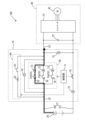
- FIG. 1 is a circuit diagram that shows a schematic diagram of an on-board power supply system including an on-board power supply device according to a first embodiment.
- FIG. 2 is an explanatory diagram for explaining the operation of the in-vehicle power supply device when the first control is executed.
- FIG. 3 is an explanatory diagram for explaining the operation of the in-vehicle power supply device when the second control is executed.
- FIG. 4 is an explanatory diagram for explaining the operation of the in-vehicle power supply device when the third control is executed.
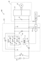
- FIG. 5 is a circuit diagram that shows a schematic diagram of an on-board power supply system including an on-board power supply device according to the fourth embodiment.
- An in-vehicle power supply device for use in an in-vehicle power supply system including a battery, a power path through which power based on the battery is supplied, and a capacitor electrically connected to the power path, a first circuit that performs a precharge operation to precharge the capacitor; a second circuit provided in the power path on the battery side relative to the capacitor; The second circuit is configured by connecting a plurality of relays in parallel.
- the above-mentioned vehicle power supply device can suppress inrush current flowing through the relays by precharging the capacitor using the first circuit and then switching the relays to the on state. Moreover, the above-mentioned vehicle power supply device can selectively use one of the multiple relays. Also, the above-mentioned vehicle power supply device can suppress inrush current flowing through each relay by switching multiple relays to the on state simultaneously. Therefore, the above-mentioned vehicle power supply device can easily extend the life of devices including relays.
- a control unit is provided to control the first circuit and the plurality of relays, The control unit is executing a first control for causing the first circuit to perform the precharge operation when a start condition for starting charging/discharging of the battery is satisfied; When a first switching condition is satisfied during execution of the first control, a second control is executed to stop the precharge operation and switch some of the relays that are switching targets among the plurality of relays to an on state;
- the in-vehicle power supply device further comprising: a third control for switching at least a part of the relays in an OFF state to an ON state when a second switching condition is satisfied during execution of the second control.
- the above-mentioned vehicle-mounted power supply device can switch only some of the relays to the on state in the second control, thereby limiting the relays through which the inrush current flows to only some, and can thereby provide electrical continuity between the battery and the capacitor via the relays. Furthermore, the above-mentioned vehicle-mounted power supply device can increase the number of relays in the on state by switching at least some of the relays in the off state to the on state when the battery and the capacitor are in electrical continuity via the relays. As a result, the above-mentioned vehicle-mounted power supply device can reduce the current flowing through each relay.
- a control unit is provided to control the first circuit and the plurality of relays, The control unit causes the first circuit to perform the precharge operation when a start condition for starting charging/discharging of the battery is satisfied, and stops the precharge operation and switches two or more of the relays to be switched on simultaneously when a switching condition is satisfied during the precharge operation.
- the above-mentioned vehicle power supply device can suppress the inrush current flowing through each relay by switching two or more relays to the on state at the same time.
- the above-mentioned automotive power supply device selects the relay to be switched in a specific order, so each relay is likely to deteriorate evenly.
- the above-mentioned automotive power supply device can reflect the results of the comparison of the deterioration levels when selecting the relay to be switched.
- the above-mentioned vehicle power supply device tends to deteriorate each relay evenly, so it is possible to more reliably achieve a long life for the device including the relay.
- the above-mentioned vehicle power supply device can use the resistance value of each relay when it is in the on state as the degree of deterioration.
- FIG. 1 shows an vehicle-mounted power supply system 100 equipped with an on-board power supply device 10.
- the vehicle-mounted power supply system 100 is used in a vehicle (not shown).
- the vehicle may be an electric vehicle, an engine vehicle, or a hybrid vehicle.
- the vehicle-mounted power supply system 100 is equipped with a battery 20, a power path 21, and a capacitor 22.
- the battery 20 may be a lithium ion battery, a lead battery, or some other type of battery.
- the power path 21 is an electrical path through which power is supplied from the battery 20.
- the power path 21 has a positive power line 30 and a negative power line 31.
- the positive terminal of the battery 20 is electrically connected to the positive power line 30.
- the negative terminal of the battery 20 is electrically connected to the negative power line 31.
- the negative power line 31 is electrically connected to the ground.
- the output voltage of the battery 20 is applied to the power path 21 (more specifically, the positive power line 30).
- voltage refers to a potential difference based on the ground potential and a potential difference based on the negative power line 31.
- the capacitor 22 is electrically connected to the power path 21.
- the capacitor 22 is provided between the positive power line 30 and the negative power line 31.
- One end of the capacitor 22 is electrically connected to the positive power line 30.
- the other end of the capacitor 22 is electrically connected to the negative power line 31.
- Power based on the battery 20 is supplied to the capacitor 22 via the power path 21.
- the capacitor 22 smoothes the voltage based on the battery 20.
- the capacitor 22 is configured as part of the drive unit 40 provided in the vehicle power supply system 100.
- the drive unit 40 includes an inverter 41 and a motor 42.
- the capacitor 22 is provided closer to the battery 20 than the inverter 41.
- the capacitor 22 smoothes the voltage based on the battery 20 and supplies it to the inverter 41.
- the inverter 41 is electrically connected to the power path 21.
- the inverter 41 generates an AC voltage (e.g., three-phase AC) from a DC voltage based on the voltage supplied from the battery 20, and supplies it to the motor 42.
- the motor 42 is, for example, a main motor.
- the motor 42 is a device that rotates based on the power supplied from the battery 20 and provides a rotational force to the wheels of the vehicle.
- the vehicle power supply device 10 is used in the vehicle power supply system 100.
- the vehicle power supply device 10 includes a relay circuit 50, a precharge circuit 60, and a second relay 70.
- the relay circuit 50 corresponds to an example of a "second circuit.”
- the relay circuit 50 is configured by connecting a plurality of first relays 51 (more specifically, first relays 51A, 51B, 51C) in parallel.
- the first relays 51 correspond to an example of a "relay.”
- the first relays 51 are a system main relay.
- the first relays 51 are mechanical relays.
- the first relays 51 have contacts.
- the ends of the first relays 51 on the battery 20 side are shorted to each other.
- the ends of the first relays 51 on the opposite side to the battery 20 side are shorted to each other.
- One end of each of the first relays 51 is electrically connected to the positive electrode of the battery 20 and is shorted to the positive electrode of the battery 20.
- the other end of each of the first relays 51 is electrically connected to one end of the capacitor 22 and is shorted to one end of the capacitor 22.
- the relay circuit 50 blocks the flow of current from the battery 20 to the capacitor 22 via the relay circuit 50.
- the relay circuit 50 conducts the positive electrode of the battery 20 to one end of the capacitor 22.
- the relay circuit 50 allows the flow of current from the battery 20 to the capacitor 22 via the relay circuit 50.
- the positive power line 30 described above includes a first positive power line 32 provided on the battery 20 side of the relay circuit 50, and a second positive power line 33 provided on the opposite side of the relay circuit 50 from the battery 20 side.
- the precharge circuit 60 performs a precharge operation to precharge the capacitor 22.
- the precharge circuit 60 is provided in parallel with the relay circuit 50.
- One end of the precharge circuit 60 is electrically connected to the first positive power line 32 and is short-circuited to the first positive power line 32.
- the other end of the precharge circuit 60 is electrically connected to the second positive power line 33 and is short-circuited to the second positive power line 33.
- the precharge circuit 60 is configured by connecting a precharge relay 61 and a resistor section 62 in series.
- the precharge relay 61 is a mechanical relay.
- the precharge relay 61 has contacts.
- the resistance unit 62 is formed, for example, by a known resistor.
- the second relay 70 is provided in the power path 21 on the battery 20 side of the capacitor 22.
- the second relay 70 is provided in the negative power line 31.
- One end of the second relay 70 is electrically connected to the negative terminal of the battery 20 and is short-circuited to the negative terminal of the battery 20.
- the other end of the second relay 70 is electrically connected to the other end of the capacitor 22 and is short-circuited to the other end of the capacitor 22.
- the second relay 70 is a system main relay.
- the second relay 70 is a mechanical relay.
- the second relay 70 has contacts.
- the in-vehicle power supply device 10 includes a control unit 71, a current detection unit 72, an individual current detection unit 73, a first voltage detection unit 74, a second voltage detection unit 75, and a temperature detection unit 76.
- the control unit 71 includes a control circuit such as an integrated circuit.
- the control unit 71 includes a processing unit such as a CPU, a storage unit such as a memory, an input/output unit, etc.
- the current detection unit 72 is configured as, for example, a known current sensor.
- the current detection unit 72 detects the value of the current flowing through the path (more specifically, the negative power line 31) of the power path 21 excluding the portion where the relay circuit 50 and the precharge circuit 60 are connected in parallel. That is, the current detection unit 72 detects the current flowing through the relay circuit 50 when a current flows only through the relay circuit 50 of the relay circuit 50 and the precharge circuit 60. Also, the current detection unit 72 detects the current flowing through the precharge circuit 60 when a current flows only through the precharge circuit 60 of the relay circuit 50 and the precharge circuit 60. The current detection unit 72 outputs a signal that can identify the detection value.
- the control unit 71 identifies the value of the current flowing through the power path 21 (more specifically, the negative power line 31) based on the output signal of the current detection unit 72.
- the control unit 71 identifies the current flowing through the precharge circuit 60 by identifying the detection value when the precharge circuit 60 is performing a precharge operation.
- the individual current detection units 73 are configured, for example, as known current sensors.
- the individual current detection units 73 are provided individually for each first relay 51.
- Each individual current detection unit 73 detects the value of the current flowing through the corresponding first relay 51 when the first relay 51 is in the on state.
- Each individual current detection unit 73 outputs a signal that can identify the detected value.
- the control unit 71 identifies the value of the current flowing through each first relay 51 based on the output signal of each individual current detection unit 73.
- the first voltage detection unit 74 is configured, for example, as a known voltage detection circuit.
- the first voltage detection unit 74 detects the potential difference between both ends of the relay circuit 50 (more specifically, the first relay 51).
- the first voltage detection unit 74 outputs a signal that can identify the detected value.
- the control unit 71 identifies the potential difference between both ends of the first relay 51 based on the output signal of the first voltage detection unit 74.
- the second voltage detection unit 75 is configured, for example, as a known voltage detection circuit.
- the second voltage detection unit 75 detects the voltage of the capacitor 22.
- the second voltage detection unit 75 outputs a signal that can identify the detected value.
- the control unit 71 identifies the voltage of the capacitor 22 based on the output signal of the second voltage detection unit 75.
- the temperature detection unit 76 is configured, for example, as a known temperature sensor.
- the temperature detection unit 76 is provided individually for each first relay 51.
- Each temperature detection unit 76 detects the temperature of the contact of the corresponding first relay 51.
- Each temperature detection unit 76 outputs a signal that can identify the detected value.
- the control unit 71 identifies the temperature of the contact of each first relay 51 based on the output signal of each temperature detection unit 76.
- the control unit 71 controls the relay circuit 50, the precharge circuit 60, and the second relay 70. In other words, the control unit 71 controls the multiple first relays 51, the precharge relays 61, and the second relays 70.
- the control unit 71 executes the first control when a start condition for starting charging/discharging of the battery 20 is satisfied.
- the first control is a control that causes the precharge circuit 60 to perform a precharge operation. More specifically, as shown in FIG. 2, the first control is a control that switches the precharge relays 61 and the second relays 70 to the ON state while maintaining all of the first relays 51 in the OFF state. In a state in which the first control is performed, power based on the battery 20 is supplied to the capacitor 22 via the precharge circuit 60.
- the current flowing through the power path 21 is suppressed by the resistor unit 62 of the precharge circuit 60. Therefore, the voltage of the capacitor 22 can be increased while suppressing damage to the first relays 51, the precharge relays 61, and the second relays 70. As the voltage of the capacitor 22 increases, the difference between the voltage of the capacitor 22 and the voltage of the battery 20 becomes smaller. As a result, the potential difference across the first relay 51 becomes smaller.
- the control unit 71 executes the second control when the first switching condition is satisfied during execution of the first control.
- the second control is a control that stops the precharge operation by the precharge circuit 60 and switches some of the first relays 51 that are the switching targets to the on state among the multiple first relays 51. More specifically, as shown in FIG. 3, the second control is a control that switches the precharge relay 61 to the off state and switches the first relay 51 that is the switching target to the on state while maintaining the second relay 70 in the on state.
- the positive electrode of the battery 20 is conducted to one end of the capacitor 22 via the relay circuit 50 (more specifically, the first relay 51), and the positive electrode of the battery 20 is short-circuited to one end of the capacitor 22.
- the voltage of the battery 20 becomes approximately the same as the voltage of the capacitor 22 in a short time, and the potential difference between both ends of the first relay 51 approaches 0V.
- the first switching condition may be that the potential difference across the first relay 51 is equal to or less than a predetermined value, that the value of the current flowing through the precharge circuit 60 is equal to or less than a predetermined value, that a predetermined time has elapsed since the start of the first control, that the voltage of the capacitor 22 is equal to or greater than a predetermined value, or some other condition.
- the number of first relays 51 to be switched may be a portion of the first relays 51 that make up the relay circuit 50, and may be one, two or more.
- the control unit 71 selects the first relay 51 to be switched in a predetermined order. For example, the control unit 71 may select the first relay 51 to be switched in the order of the first relay 51A, the first relay 51B, and the first relay 51C. In this case, for example, the control unit 71 selects the first relay 51A in the current second control, and selects the first relay 51B in the next second control. In this case, the control unit 71 switches the first relay 51 to be switched each time the first switching condition is satisfied. In contrast, the control unit 71 may switch the first relay 51 to be switched each time a predetermined condition is satisfied.
- the predetermined condition may be, for example, that the first relay 51 to be switched has been switched to the on state a predetermined number of times in succession, that the deterioration level of the first relay 51 to be switched has exceeded a threshold, or that it may be another condition.
- the deterioration level will be described in detail later.
- the predetermined order may be changeable.
- the control unit 71 executes the third control when the second switching condition is met while the second control is being executed.
- the third control is a control for increasing the number of first relays 51 in the ON state. More specifically, the third control is a control for switching at least some of the first relays 51 in the OFF state to the ON state. For example, as shown in FIG. 4, the control unit 71 switches all the first relays 51 in the OFF state to the ON state in the third control. In other words, the control unit 71 controls all the first relays 51 to the ON state in the third control.
- a current flows in the power path 21 via the multiple first relays 51 controlled to the ON state.
- the second switching condition is preferably a condition that is met when the potential difference across the first relay 51 becomes close to 0 V.
- the second switching condition may be that the potential difference across the first relay 51 becomes equal to or less than a predetermined value, that the value of the current flowing through the precharge circuit 60 becomes equal to or less than a predetermined value, that a predetermined time has elapsed since the start of the first control, that the voltage of the capacitor 22 becomes equal to or greater than a predetermined value, or any other condition.
- each first relay 51 is determined based on, for example, the potential difference between both ends of the first relay 51 when all the other first relays 51 are in an OFF state and the target first relay 51 is in an ON state (hereinafter also referred to as the "potential difference between both ends of the target first relay 51"), the value of the current flowing through the first relay 51, the resistance value when the first relay 51 is in an ON state, the number of operations of the first relay 51, the temperature of the contacts when the first relay 51 is in an ON state, a combination of a plurality of these, and the like.
- the deterioration degree of each first relay 51 may be the above-mentioned exemplified value itself, or may be a value obtained by substituting the exemplified value into an arithmetic expression.
- the temperature of the contacts when the first relay 51 is in an ON state depends not only on the deterioration degree (e.g., resistance value) of the first relay 51 but also on the value of the current flowing through the first relay 51.
- the degree of deterioration of the first relay 51 is determined based on the temperature of the contacts when the first relay 51 is in the on state, it is preferable that the degree of deterioration of the first relay 51 is determined based on the temperature of the contacts when the first relay 51 is in the on state and the value of the current flowing through the first relay 51.
- the degree of deterioration of the first relay 51 increases as the potential difference between both ends of the target first relay 51 increases.
- the degree of deterioration of the first relay 51 increases as the value of the current flowing through the first relay 51 decreases.
- the degree of deterioration of the first relay 51 increases as the resistance value of the first relay 51 when it is in the on state increases.
- the degree of deterioration of the first relay 51 increases as the number of times the first relay 51 operates increases.
- the degree of deterioration of the first relay 51 increases as the temperature of the contacts when the first relay 51 is in the on state increases, assuming that the value of the current flowing through the first relay 51 is constant.
- the control unit 71 sequentially switches the first relays 51 to be turned on and identifies the potential difference across the first relays 51 when each first relay 51 is turned on.
- the identification start timing may be, for example, while the third control is being executed.
- the control unit 71 identifies the value of the current flowing through each of the first relays 51, for example, based on the output signal of each individual current detection unit 73. As another example, the control unit 71 sequentially switches the first relays 51 to be turned on, and identifies the value of the current flowing through each of the first relays 51 based on the output signal of the current detection unit 72 when each of the first relays 51 is turned on.
- the timing to start identifying the current may be, for example, while the third control is being executed.
- the control unit 71 determines the potential difference between both ends of the target first relay 51 and the value of the current flowing through each first relay 51, for example, by the method described above as a method for determining the resistance value when the first relay 51 is in the on state. The control unit 71 then determines the resistance value of each first relay 51 based on the determined potential difference and current value.
- the determination start timing may be, for example, while the third control is being executed.
- the control unit 71 determines the number of times the first relay 51 operates by, for example, counting the number of times each first relay 51 is switched to the on state in the second control.
- the control unit 71 determines the temperature of the contacts when each first relay 51 is in the on state, for example, based on the output signal of each temperature detection unit 76.
- the in-vehicle power supply device 10 can suppress the flow of inrush current to the first relay 51 by precharging the capacitor 22 using the precharge circuit 60 and then switching the first relay 51 to the on state. Moreover, the in-vehicle power supply device 10 can selectively use one of the multiple first relays 51. Therefore, the in-vehicle power supply device 10 can easily extend the life of the devices including the first relays 51.
- the in-vehicle power supply device 10 can switch only some of the first relays 51 to the on state in the second control, thereby limiting the first relays 51 through which the inrush current flows to only some, and can conduct the battery 20 and the capacitor 22 via the first relays 51. Furthermore, the in-vehicle power supply device 10 can increase the number of first relays 51 in the on state by switching at least some of the first relays 51 in the off state to the on state when the battery 20 and the capacitor 22 are in conduction via the first relays 51. As a result, the in-vehicle power supply device 10 can reduce the current flowing through each of the first relays 51.
- the vehicle power supply device 10 selects the first relay 51 to be switched in a specific order, which makes it easier for each first relay 51 to deteriorate evenly.
- the vehicle power supply device 10 can measure the resistance value of each first relay 51 when it is in the on state to determine the degree of deterioration. With this configuration, the vehicle power supply device 10 can use the resistance value of each first relay 51 when it is in the on state as the degree of deterioration.
- the first relays 51 to be switched are selected in a predetermined order.
- a configuration is described in which the deterioration levels of the first relays 51 are determined and compared, and the first relays 51 to be switched are selected based on the comparison results.
- differences from the first embodiment are mainly described. Note that the in-vehicle power supply system of the second embodiment has the same configuration as that of FIG. 1 described in the first embodiment. For this reason, the second embodiment will be described with reference to FIG. 1.
- the control unit 71 determines the degree of deterioration of each of the first relays 51. Then, the control unit 71 compares the determined degrees of deterioration and selects the first relay 51 to be switched based on the comparison result. More specifically, the control unit 71 selects the first relay 51 with the smallest degree of deterioration as the first relay 51 to be switched. Note that, if the number of switching targets is two or more, the control unit 71 selects two or more first relays 51 in order of decreasing degree of deterioration. For example, if the number of switching targets is two, the control unit 71 selects the second first relay 51 with the smallest degree of deterioration.
- the in-vehicle power supply device 10 of the second embodiment can reflect the comparison result of the deterioration degree in the selection of the first relay 51 to be switched. Furthermore, the in-vehicle power supply device 10 of the second embodiment can more reliably achieve a long life for the device including the first relays 51 because it is easy to cause each first relay 51 to deteriorate evenly.
- the control unit 71 switches two or more first relays 51 that are switching targets to the on state at the same time.
- differences from the first embodiment will be mainly described. Note that the in-vehicle power supply system of the third embodiment has the same configuration as that of FIG. 1 described in the first embodiment. Therefore, the third embodiment will be described with reference to FIG. 1.
- the control unit 71 stops the precharge operation by the precharge circuit 60 and simultaneously switches two or more first relays 51 that are switching targets to the on state.
- the control unit 71 causes the precharge circuit 60 to perform a precharge operation, and when a first switching condition is satisfied during the precharge operation, the control unit 71 stops the precharge operation and simultaneously switches two or more first relays 51 that are switching targets to the on state.
- the number of first relays 51 to be switched is a portion of the first relays 51 that constitute the relay circuit 50.
- the number of first relays 51 to be switched may be all of the first relays 51 that constitute the relay circuit 50.
- the in-vehicle power supply device 10 of the third embodiment can suppress the inrush current flowing through each first relay 51 by switching two or more first relays 51 to the on state at the same time.
- the fourth embodiment of the in-vehicle power supply system 400 shown in FIG. 5 differs from the in-vehicle power supply system 100 of the first embodiment in that it does not include a precharge circuit 60, but includes a low-voltage battery 90 and a DCDC converter 91, but is otherwise common to both.
- the fourth embodiment of the vehicle power supply system 400 includes a battery 20, a power path 21, a capacitor 22, a low-voltage battery 90, and a vehicle power supply device 410.
- the low-voltage battery 90 is a battery that has a lower output voltage when fully charged compared to the battery 20.
- the battery 20 can be said to be a "high-voltage battery.”
- the low-voltage battery 90 may be a lead battery, a lithium-ion battery, or another battery.
- the vehicle power supply device 410 includes a relay circuit 50, a second relay 70, a control unit 71, a current detection unit 72, an individual current detection unit 73, a first voltage detection unit 74, a second voltage detection unit 75, a temperature detection unit 76, and a DCDC converter 91.
- the DCDC converter 91 corresponds to an example of a "first circuit.”
- the DCDC converter 91 performs a first operation of converting (in this embodiment, stepping down) the voltage applied to the first conductive path 92 and applying it to the second conductive path 93.
- the DCDC converter 91 also performs a second operation of converting (in this embodiment, stepping up) the voltage applied to the second conductive path 93 and applying it to the first conductive path 92.
- the first conductive path 92 is electrically connected to the power path 21, and is electrically connected to the capacitor 22 via the power path 21.
- the first conductive path 92 is short-circuited to the capacitor 22.
- the low-voltage battery 90 is connected to the second conductive path 93.
- the control unit 71 controls the DCDC converter 91.
- the control unit 71 causes the DCDC converter 91 to perform a first operation, thereby charging the low-voltage battery 90.
- "When power is being supplied from the battery 20 to the power path 21" refers to when at least one first relay 51 is in the ON state and the second relay 70 is in the ON state.
- the control unit 71 causes the DCDC converter 91 to perform the second operation, thereby boosting the voltage based on the low-voltage battery 90 and applying it to the first conductive path 92.
- a voltage is applied to the capacitor 22 based on the voltage applied to the first conductive path 92.
- the DCDC converter 91 can perform a precharge operation to precharge the capacitor 22.
- the DCDC converter 91 raises the voltage of the capacitor 22 to a voltage similar to that of the battery 20.
- the operation of raising the voltage of the capacitor 22 to a voltage similar to that of the battery 20 by the second operation is the precharge operation.
- the control unit 71 When the start condition is met, the control unit 71 causes the DCDC converter 91 to perform a precharge operation. Thereafter, when the first switching condition described in the first embodiment is met, the control unit 71 stops the precharge operation by the DCDC converter 91 and switches the first relay 51 and the second relay 70 to the on state.
- the first relays 51 that are switched to the on state may be some or all of them. If only some of the first relays 51 are switched to the on state, then the third control described in the first embodiment may be executed.
- the in-vehicle power supply device 410 of the fourth embodiment can precharge the capacitor 22 using a DCDC converter 91 that charges the low-voltage battery 90. This eliminates the need for the precharge circuit 60 described in the first embodiment. Furthermore, in the case of the precharge circuit 60, the voltage of the capacitor 22 becomes less likely to rise as it approaches the voltage of the battery 20. In contrast, in a configuration that uses a DCDC converter 91, the voltage of the capacitor 22 can be quickly raised to the voltage of the battery 20.
- the second relay 70 does not have to be provided.
- Each of the above embodiments may be configured so that the third control is not executed.
- the relay circuit 50 and the precharge circuit 60 are provided on the positive power line 30, but the relay circuit 50 and the precharge circuit 60 may be provided on the negative power line 31.
Landscapes
- Engineering & Computer Science (AREA)
- Power Engineering (AREA)
- Life Sciences & Earth Sciences (AREA)
- Sustainable Development (AREA)
- Sustainable Energy (AREA)
- Transportation (AREA)
- Mechanical Engineering (AREA)
- Electric Propulsion And Braking For Vehicles (AREA)
- Charge And Discharge Circuits For Batteries Or The Like (AREA)
- Direct Current Feeding And Distribution (AREA)
- Emergency Protection Circuit Devices (AREA)
- Protection Of Static Devices (AREA)
Abstract
Description
バッテリと、前記バッテリに基づく電力が供給される電力路と、前記電力路に電気的に接続されるコンデンサと、を備える車載用電源システムに用いられる車載用電源装置であって、
前記コンデンサをプリチャージするプリチャージ動作を行う第1回路と、
前記コンデンサよりも前記バッテリ側において前記電力路に設けられる第2回路と、を備え、
前記第2回路は、複数のリレーを並列に接続した構成をなす。
前記コンデンサをプリチャージするプリチャージ動作を行う第1回路と、
前記コンデンサよりも前記バッテリ側において前記電力路に設けられる第2回路と、を備え、
前記第2回路は、複数のリレーを並列に接続した構成をなす
車載用電源装置。
前記制御部は、
前記バッテリの充放電を開始させる開始条件が成立した場合に、前記第1回路に前記プリチャージ動作を行わせる第1制御を実行し、
前記第1制御の実行中に第1切替条件が成立した場合に、前記プリチャージ動作を停止させ且つ前記複数のリレーのうち一部の切替対象の前記リレーをオン状態に切り替える第2制御を実行し、
前記第2制御の実行中に第2切替条件が成立した場合に、オフ状態の前記リレーの少なくとも一部をオン状態に切り替える第3制御を実行する
〔1〕に記載の車載用電源装置。
前記制御部は、前記バッテリの充放電を開始させる開始条件が成立した場合に、前記第1回路に前記プリチャージ動作を行わせ、前記プリチャージ動作中に切替条件が成立した場合に、前記プリチャージ動作を停止させ且つ2以上の切替対象の前記リレーを同時期にオン状態に切り替える
〔1〕に記載の車載用電源装置。
〔2〕又は〔3〕に記載の車載用電源装置。
〔2〕又は〔3〕に記載の車載用電源装置。
〔5〕に記載の車載用電源装置。
〔5〕又は〔6〕に記載の車載用電源装置。
1.車載用電源システム100の構成
図1には、車載用電源装置10を備えた車載用電源システム100が示されている。車載用電源システム100は、図示しない車両に用いられる。車両は、電気自動車であってもよいし、エンジン車であってもよいし、ハイブリッド車であってもよい。車載用電源システム100は、車載用電源装置10の他に、バッテリ20と、電力路21と、コンデンサ22と、を備える。
車載用電源装置10は、制御部71と、電流検出部72と、個別電流検出部73と、第1電圧検出部74と、第2電圧検出部75と、温度検出部76と、を備える。
各々の第1リレー51の劣化度は、例えば、他の第1リレー51が全てオフ状態で且つ対象の第1リレー51がオン状態であるときの第1リレー51の両端の電位差(以下、「対象の第1リレー51の両端の電位差」ともいう)、第1リレー51を流れる電流の値、第1リレー51のオン状態のときの抵抗値、第1リレー51の動作回数、第1リレー51のオン状態のときの接点の温度、これらの複数の組み合わせ、などに基づいて特定される。各々の第1リレー51の劣化度は、上記の例示した値そのものであってもよいし、例示した値を演算式に代入して得られる値であってもよい。第1リレー51のオン状態のときの接点の温度は、第1リレー51の劣化度(例えば抵抗値)のみでなく、第1リレー51を流れる電流の値にも依存する。このため、第1リレー51の劣化度が第1リレー51のオン状態のときの接点の温度に基づいて特定される構成においては、第1リレー51の劣化度が第1リレー51のオン状態のときの接点の温度と第1リレー51を流れる電流の値とに基づいて特定されることが好ましい。
車載用電源装置10は、プリチャージ回路60によってコンデンサ22をプリチャージしてから第1リレー51をオン状態に切り替えることで、第1リレー51に突入電流が流れることを抑えることができる。しかも、車載用電源装置10は、複数の第1リレー51のいずれかを選択的に使用することができる。このため、車載用電源装置10は、第1リレー51を含む装置の長寿命化を図りやすい。
第1実施形態では、切替対象の第1リレー51を所定の順序で選択する構成であった。これに対し、第2実施形態では、各々の第1リレー51の劣化度を判定して比較し、比較結果に基づいて切替対象の第1リレー51を選択する構成について説明する。第2実施形態では、主に第1実施形態と異なる点について説明する。なお、第2実施形態の車載用電源システムは、第1実施形態で説明した図1の構成と同じである。このため、第2実施形態は、図1を参照して説明される。
第3実施形態では、制御部71が、2以上の切替対象の第1リレー51を同時期にオン状態に切り替える構成について説明する。第3実施形態では、主に第1実施形態と異なる点について説明する。なお、第3実施形態の車載用電源システムは、第1実施形態で説明した図1の構成と同じである。このため、第3実施形態は、図1を参照して説明される。
第4実施形態では、プリチャージ回路60ではなく、DCDCコンバータによってプリチャージ動作を行う例について説明する。なお、第1実施形態と同じ構成について同じ符号を付し、詳しい説明を省略する。
本開示は、上記記述及び図面によって説明した実施形態に限定されるものではない。例えば、上述又は後述の実施形態の特徴は、矛盾しない範囲であらゆる組み合わせが可能である。また、上述又は後述の実施形態のいずれの特徴も、必須のものとして明示されていなければ省略することもできる。更に、上述した実施形態は、次のように変更されてもよい。
20…バッテリ
21…電力路
22…コンデンサ
30…正極側電力線
31…負極側電力線
32…第1正極側電力線
33…第2正極側電力線
40…駆動部
41…インバータ
42…モータ
50…リレー回路(第2回路)
51…第1リレー(リレー)
51A…第1リレー(リレー)
51B…第1リレー(リレー)
51C…第1リレー(リレー)
60…プリチャージ回路(第1回路)
61…プリチャージリレー
62…抵抗部
70…第2リレー
71…制御部
72…電流検出部
73…個別電流検出部
74…第1電圧検出部
75…第2電圧検出部
76…温度検出部
90…低圧バッテリ
91…DCDCコンバータ(第1回路)
92…第1導電路
93…第2導電路
100…車載用電源システム
400…車載用電源システム
410…車載用電源装置
Claims (7)
- バッテリと、前記バッテリに基づく電力が供給される電力路と、前記電力路に電気的に接続されるコンデンサと、を備える車載用電源システムに用いられる車載用電源装置であって、
前記コンデンサをプリチャージするプリチャージ動作を行う第1回路と、
前記コンデンサよりも前記バッテリ側において前記電力路に設けられる第2回路と、を備え、
前記第2回路は、複数のリレーを並列に接続した構成をなす
車載用電源装置。 - 前記第1回路及び前記複数のリレーを制御する制御部を備え、
前記制御部は、
前記バッテリの充放電を開始させる開始条件が成立した場合に、前記第1回路に前記プリチャージ動作を行わせる第1制御を実行し、
前記第1制御の実行中に第1切替条件が成立した場合に、前記プリチャージ動作を停止させ且つ前記複数のリレーのうち一部の切替対象の前記リレーをオン状態に切り替える第2制御を実行し、
前記第2制御の実行中に第2切替条件が成立した場合に、オフ状態の前記リレーの少なくとも一部をオン状態に切り替える第3制御を実行する
請求項1に記載の車載用電源装置。 - 前記第1回路及び前記複数のリレーを制御する制御部を備え、
前記制御部は、前記バッテリの充放電を開始させる開始条件が成立した場合に、前記第1回路に前記プリチャージ動作を行わせ、前記プリチャージ動作中に切替条件が成立した場合に、前記プリチャージ動作を停止させ且つ2以上の切替対象の前記リレーを同時期にオン状態に切り替える
請求項1に記載の車載用電源装置。 - 前記制御部は、前記切替対象の前記リレーが前記複数のリレーの一部である場合に、所定の順序に従って前記切替対象の前記リレーを選択する
請求項2又は請求項3に記載の車載用電源装置。 - 前記制御部は、前記切替対象の前記リレーが前記複数のリレーの一部である場合に、各々の前記リレーの劣化度を判定して比較し、比較結果に基づいて前記切替対象の前記リレーを選択する
請求項2又は請求項3に記載の車載用電源装置。 - 前記制御部は、前記劣化度の最も小さい前記リレーを、前記切替対象の前記リレーとして選択する
請求項5に記載の車載用電源装置。 - 前記制御部は、前記劣化度の判定として、各々の前記リレーについてオン状態のときの抵抗値を測定する
請求項5に記載の車載用電源装置。
Priority Applications (2)
| Application Number | Priority Date | Filing Date | Title |
|---|---|---|---|
| CN202380078662.8A CN120153545A (zh) | 2022-11-29 | 2023-11-08 | 车载用电源装置 |
| US19/128,607 US20260094779A1 (en) | 2022-11-29 | 2023-11-08 | In-vehicle power supply device |
Applications Claiming Priority (2)
| Application Number | Priority Date | Filing Date | Title |
|---|---|---|---|
| JP2022190199A JP2024077944A (ja) | 2022-11-29 | 2022-11-29 | 車載用電源装置 |
| JP2022-190199 | 2022-11-29 |
Publications (1)
| Publication Number | Publication Date |
|---|---|
| WO2024116752A1 true WO2024116752A1 (ja) | 2024-06-06 |
Family
ID=91323489
Family Applications (1)
| Application Number | Title | Priority Date | Filing Date |
|---|---|---|---|
| PCT/JP2023/040159 Ceased WO2024116752A1 (ja) | 2022-11-29 | 2023-11-08 | 車載用電源装置 |
Country Status (4)
| Country | Link |
|---|---|
| US (1) | US20260094779A1 (ja) |
| JP (1) | JP2024077944A (ja) |
| CN (1) | CN120153545A (ja) |
| WO (1) | WO2024116752A1 (ja) |
Families Citing this family (1)
| Publication number | Priority date | Publication date | Assignee | Title |
|---|---|---|---|---|
| JP7828025B1 (ja) * | 2024-09-30 | 2026-03-11 | ダイキン工業株式会社 | 電源装置 |
Citations (3)
| Publication number | Priority date | Publication date | Assignee | Title |
|---|---|---|---|---|
| KR20130095493A (ko) * | 2012-02-20 | 2013-08-28 | 계명대학교 산학협력단 | 전기 차량의 전력 공급을 위한 릴레이 장치 및 그 구동 제어 방법 |
| JP2021106453A (ja) * | 2019-12-26 | 2021-07-26 | 日立Astemo株式会社 | 負荷回路装置および負荷回路装置の制御方法 |
| WO2021235367A1 (ja) * | 2020-05-18 | 2021-11-25 | ファナック株式会社 | 並列駆動されるスイッチの故障を検出する故障検出装置及びモータ駆動装置 |
-
2022
- 2022-11-29 JP JP2022190199A patent/JP2024077944A/ja active Pending
-
2023
- 2023-11-08 CN CN202380078662.8A patent/CN120153545A/zh active Pending
- 2023-11-08 US US19/128,607 patent/US20260094779A1/en active Pending
- 2023-11-08 WO PCT/JP2023/040159 patent/WO2024116752A1/ja not_active Ceased
Patent Citations (3)
| Publication number | Priority date | Publication date | Assignee | Title |
|---|---|---|---|---|
| KR20130095493A (ko) * | 2012-02-20 | 2013-08-28 | 계명대학교 산학협력단 | 전기 차량의 전력 공급을 위한 릴레이 장치 및 그 구동 제어 방법 |
| JP2021106453A (ja) * | 2019-12-26 | 2021-07-26 | 日立Astemo株式会社 | 負荷回路装置および負荷回路装置の制御方法 |
| WO2021235367A1 (ja) * | 2020-05-18 | 2021-11-25 | ファナック株式会社 | 並列駆動されるスイッチの故障を検出する故障検出装置及びモータ駆動装置 |
Also Published As
| Publication number | Publication date |
|---|---|
| JP2024077944A (ja) | 2024-06-10 |
| US20260094779A1 (en) | 2026-04-02 |
| CN120153545A (zh) | 2025-06-13 |
Similar Documents
| Publication | Publication Date | Title |
|---|---|---|
| JP5440400B2 (ja) | 電源装置 | |
| US8643500B2 (en) | Apparatus and method for diagnosing abnormality in cell balancing circuit | |
| CN108349406B (zh) | 电动车辆的驱动电路及其控制方法 | |
| US7710067B2 (en) | Power supply system and power supply system control method | |
| US10348107B2 (en) | Battery device | |
| EP3922503B1 (en) | Load access detection method, switch circuit and battery management system | |
| CN111433613A (zh) | 计测装置、蓄电装置、计测系统、偏移误差的计测方法 | |
| KR102663546B1 (ko) | 차량의 고전압 직류 링크 커패시터의 프리차지 방법 및 시스템 | |
| CN110361598B (zh) | 接地故障检测设备 | |
| US20200064388A1 (en) | Ground fault detection apparatus | |
| JP2013205257A (ja) | 電源装置、及びこの電源装置を備える車両並びに蓄電装置 | |
| KR20170097481A (ko) | 컨택터의 상태를 진단하는 충방전 시스템 및 방법 | |
| CN103765001A (zh) | 车辆用电源装置 | |
| CN110361669B (zh) | 电池劣化判定装置 | |
| EP4267422B1 (en) | Power delivery control system for an electric vehicle and diagnostic method therefor | |
| WO2024116752A1 (ja) | 車載用電源装置 | |
| JP2014193060A (ja) | 電源装置 | |
| KR101602434B1 (ko) | 충전시 발생하는 셀 밸런싱 스위치의 오진단 방지 장치 및 오진단 방지 방법 | |
| JP2006238509A (ja) | 電動車輌の制御装置、電動車輌の制御方法、プログラム及びコンピュータ可読記録媒体 | |
| JP2018127085A (ja) | 地絡検出装置、電源システム | |
| JP7391482B2 (ja) | 地絡検出装置 | |
| JP6607161B2 (ja) | 車載電池システムの制御方法 | |
| KR20150083802A (ko) | 배터리의 부하 스위치의 기능성 검출 방법, 및 배터리의 부하 스위치의 기능성 검출 장치를 구비한 배터리 | |
| CN118665261A (zh) | 用于启动车载电气系统的方法和装置 | |
| JP7799936B2 (ja) | 車載用電源装置 |
Legal Events
| Date | Code | Title | Description |
|---|---|---|---|
| 121 | Ep: the epo has been informed by wipo that ep was designated in this application |
Ref document number: 23897406 Country of ref document: EP Kind code of ref document: A1 |
|
| WWE | Wipo information: entry into national phase |
Ref document number: CN2023800786628 Country of ref document: CN Ref document number: 202380078662.8 Country of ref document: CN |
|
| WWP | Wipo information: published in national office |
Ref document number: 202380078662.8 Country of ref document: CN |
|
| NENP | Non-entry into the national phase |
Ref country code: DE |
|
| 122 | Ep: pct application non-entry in european phase |
Ref document number: 23897406 Country of ref document: EP Kind code of ref document: A1 |