WO2024111123A1 - 仮想空間体感システム及び仮想空間体感方法 - Google Patents
仮想空間体感システム及び仮想空間体感方法 Download PDFInfo
- Publication number
- WO2024111123A1 WO2024111123A1 PCT/JP2022/043614 JP2022043614W WO2024111123A1 WO 2024111123 A1 WO2024111123 A1 WO 2024111123A1 JP 2022043614 W JP2022043614 W JP 2022043614W WO 2024111123 A1 WO2024111123 A1 WO 2024111123A1
- Authority
- WO
- WIPO (PCT)
- Prior art keywords
- area
- virtual
- real
- virtual space
- user
- Prior art date
- Legal status (The legal status is an assumption and is not a legal conclusion. Google has not performed a legal analysis and makes no representation as to the accuracy of the status listed.)
- Ceased
Links
Images



Classifications
-
- G—PHYSICS
- G06—COMPUTING OR CALCULATING; COUNTING
- G06T—IMAGE DATA PROCESSING OR GENERATION, IN GENERAL
- G06T19/00—Manipulating three-dimensional [3D] models or images for computer graphics
Definitions
- the present invention relates to a virtual space experience system and a virtual space experience method that allow a user to experience a virtual space via an environment output device that allows the user to recognize the environment of the virtual space.
- HMD head-mounted display
- This type of virtual space experience system uses a motion capture device or the like to recognize the user's position and movement in real space (i.e., coordinate movement and posture change, etc.), and then moves and operates an avatar corresponding to the user in the virtual space according to the recognized position and movement (see, for example, Patent Document 1).
- the present invention has been made in consideration of the above points, and aims to provide a system and method for experiencing a virtual space in which the shape and size of the virtual space are not likely to be restricted by the shape and size of the real space, making it easy to maintain a sense of immersion.
- the virtual space experience system of the present invention comprises: a virtual space generation unit that generates a virtual space corresponding to a real space in which a user exists; an avatar generation unit that generates an avatar corresponding to the user in the virtual space; A user state recognition unit that recognizes the position and action of the user; an avatar state control unit that controls a position and a movement of the avatar based on a position and a movement of the user; an environment determination unit that determines an environment in the virtual space to be recognized by the user based on a position and a movement of the avatar; A virtual space experiencing system that allows a user to experience a virtual space via an environment output device that outputs an environment of the virtual space, the virtual space generation unit generates, in the virtual space, a first virtual area corresponding to a first real area in the real space and a second virtual area corresponding to a second real area in the real space adjacent to the first real area; A positional relationship between the first virtual area and the second virtual area is different from a positional relationship between the first real area and the second real
- the virtual space includes a first virtual area corresponding to a first real area in real space, and a second virtual area corresponding to a second real area in real space adjacent to the first real area.
- a first virtual area corresponding to a first real area in real space
- a second virtual area corresponding to a second real area in real space adjacent to the first real area.
- one specific area in real space is divided, and an independent virtual area is assigned to each of the divided areas.
- the positional relationship between the first virtual area and the second virtual area is made different from the positional relationship between the first real area and the second real area.
- this system makes it possible to make the size and shape of the entire virtual space different from the size and shape of the real space depending on the position of the virtual area (i.e., how it is arranged). For example, if two virtual areas are positioned offset in the vertical direction, the height of the entire virtual space can be made higher than the height of the corresponding entire real space.
- this system makes it possible for the user to experience a wide variety of virtual spaces that would not be possible in real space.
- the shape and size of the virtual space are made different from the shape and size of the corresponding real space by changing the positional relationship of the virtual regions in this way, the correspondence between the amount of movement and action of the user and the amount of movement and action of the avatar can be maintained constant, unlike when the shape and size of the virtual space are made different from the shape and size of the corresponding real space by transforming the shape and size of the virtual space.
- this system makes it possible for the user to feel less uncomfortable between their own movements and actions and those of their avatar, allowing them to maintain the awareness that they are present in a virtual space (i.e., a sense of immersion).
- the first virtual area and the second virtual area are spaced apart from each other, It is preferable that a third virtual area is disposed between the first virtual area and the second virtual area, the third virtual area corresponding to a third real area that does not correspond to the real space or is independent of the first real area and the second real area.
- an edge of the first virtual area corresponds to an edge of the second real area.
- first virtual area and the second virtual area are positioned apart from each other and a third virtual area is positioned between them, when the user moves from the first real area to the second real area, the avatar will move from the first virtual area to the second virtual area, jumping over the third virtual area.
- the sudden movement of the avatar may give the user a sense of discomfort and hinder the sense of immersion.
- the edge of the first virtual area corresponds to the edge of the second real area.
- the edge of the first virtual area corresponds to the edge of the second real area
- the color tone of the edge of the first virtual area is different from the color tone of the other part of the first virtual area.
- This configuration allows the user to easily recognize the boundary portion (i.e., the boundary portion of the first area) before the avatar enters the edge. This makes the user aware that some kind of change will occur at the boundary portion. This makes it less likely that the user will feel uncomfortable even when the avatar enters the boundary portion and causes a sudden movement of the avatar, making it less likely that the sense of immersion will be hindered.
- the edge of the first virtual area corresponds to the edge of the second real area
- the portion of the avatar located at the edge of the first virtual area has a form different from other portions of the avatar.
- the user can easily recognize the boundary portion. In turn, the user can be made aware that some kind of change will occur at the boundary portion. This makes it less likely that the user will feel uncomfortable even when the avatar enters the boundary portion and causes a sudden movement of the avatar, making it less likely that the sense of immersion will be hindered.
- a correspondence relationship between the coordinate axes of the first real area and the coordinate axes of the first virtual area may be different from a correspondence relationship between the coordinate axes of the second real area and the coordinate axes of the second virtual area.
- the virtual space is a space that does not exist in real space. For example, if the coordinate axes of the first virtual realm are made to coincide with those of the first real realm and the coordinate axes of the second virtual realm are made to be upside down compared to those of the second real realm, then it is possible to realize a virtual space in which the top and bottom are reversed by moving from the first virtual realm to the second virtual realm.
- the virtual space experiencing method of the present invention comprises: A step in which a virtual space generation unit generates a virtual space corresponding to a real space in which a user exists; an avatar generation unit generating an avatar corresponding to the user in the virtual space; A user state recognition unit recognizes a position and a movement of the user; an avatar state control unit controlling a position and a movement of the avatar based on a position and a movement of the user; an environment determination unit determining an environment in a virtual space to be recognized by the user based on a position and a movement of the avatar; a step of outputting an environment of the virtual space to the user by an environment output device, the virtual space generation unit generates, in the virtual space, a first virtual area corresponding to a first real area in the real space and a second virtual area corresponding to a second real area in the real space adjacent to the first real area; A positional relationship between the first virtual area and the second virtual area is different from a positional relationship between the first real area and the second real area.
- FIG. 1 is a schematic diagram showing a general configuration of a VR system according to a first embodiment.
- FIG. 2 is a block diagram showing the configuration of the VR system shown in FIG. 1 .
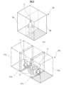
- FIG. 2 is a perspective view showing the state of real space and virtual space when the VR system of FIG. 1 is used.
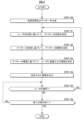
- 4 is a flowchart showing a process executed by the VR system of FIG. 1 .
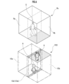
- 13 is a perspective view showing the state of real space and virtual space when using the VR system of the second embodiment.
- FIG. FIG. 13 is a perspective view showing the state of real space and virtual space when using the VR system of the third embodiment.
- the VR system S allows a user U present in a real space RS (e.g., a room) to recognize the environment (e.g., images, sounds, etc.) of a virtual space VS1 that corresponds to the real space RS, and also makes the user U recognize that he or she exists in the virtual space VS1 by moving or moving an avatar A corresponding to the user U in the virtual space VS1 to correspond to the user U (see Figure 3, etc.).
- a real space RS e.g., a room
- the environment e.g., images, sounds, etc.
- the virtual space experience system of the present invention is not limited to such a configuration, and the number of users may be two or more.
- the VR system S includes a number of signs 1 that are attached to a user U in a real space RS, a camera 2 that photographs the user U (or, more precisely, the signs 1 attached to the user U), a server 3 that determines images and sounds in a virtual space VS1 (see FIG. 3), and a head-mounted display (hereinafter referred to as "HMD 4") that allows the user to recognize the determined images and sounds.
- HMD 4 head-mounted display
- the camera 2, server 3, and HMD 4 can wirelessly transmit and receive information between each other via the Internet network, public lines, short-distance wireless communication, etc. However, any of them may also be configured to transmit and receive information between each other via wires.
- the multiple signs 1 are attached to the user U's head, both hands, and both feet via the HMD 4, gloves, and shoes worn by the user U.
- the multiple signs 1 are used to recognize the amount of movement and action of the user U in the real space RS, as described below. Therefore, the positions at which the signs 1 are attached, the number of signs 1 attached, etc. may be changed as appropriate depending on the other devices that make up the VR system S.
- Camera 2 is installed so that it can capture the user U's range of motion (i.e., the range within which user U can move and act) in the real space RS in which user U exists from multiple directions.
- the server 3 recognizes the sign 1 from the image captured by the camera 2, and recognizes the coordinates and posture (and thus the amount of movement and action) of the user U based on the position of the recognized sign 1 in the real space RS.
- the server 3 also determines the environment of the virtual space VS1 (e.g., images, sounds, etc.) that the user U will recognize based on the coordinates and posture.
- the HMD4 is an environment output device that outputs the environment of the virtual space VS1 to the user so that the user can recognize it.
- the HMD4 is worn on the head of the user U.
- the HMD4 has a monitor 40 that allows the user U to recognize an image of the virtual space VS1 determined by the server 3, and a speaker 41 that allows the user U to recognize the sound of the virtual space VS1 determined by the server 3 (see Figure 2).
- the user U When experiencing the virtual space VS1 using the VR system S, the user U is made to perceive only the images and sounds of the virtual space VS1 via the HMD 4, and is made to perceive that he or she is present in the virtual space VS1.
- the VR system S is configured as a so-called immersive system.
- the virtual space experience system of the present invention is not limited to such a configuration.
- a configuration in which the number and arrangement of signs and cameras are different from the above configuration may be used.
- feature points may be recognized from the image of the user itself to recognize the user's posture and coordinates.
- a motion capture device instead of a motion capture device, another device may be used to recognize the user's state.
- a sensor such as a GPS may be mounted on the HMD, and the user's coordinates, posture, etc. may be recognized based on the output from the sensor.
- a sensor may be used in combination with the motion capture device described above.
- the server 3 is composed of one or more electronic circuit units including a CPU, RAM, ROM, interface circuits, etc. As shown in FIG. 2, the server 3 has a virtual environment generation unit 30, a user state recognition unit 31, an avatar state control unit 32, and an environment determination unit 33 as functions (processing units) realized by the implemented hardware configuration or programs.
- the virtual environment generation unit 30 has a virtual space generation unit 30a and an avatar generation unit 30b.
- the virtual space generation unit 30a generates a virtual space VS1 that corresponds to the real space RS in which the user U exists. Specifically, the virtual space generation unit 30a generates images that represent the background of the virtual space VS and objects that exist in the virtual space VS, as well as sounds associated with these images.
- the VR system S of this embodiment does not have such a feature
- the virtual space experience system has a feature for realizing a specific sensation (such as a cushion with variable hardness) or a feature for generating a specific smell
- the virtual space generation unit may generate the virtual space using the sensation and smell in addition to the images and sounds.
- the avatar generation unit 30b generates an avatar A corresponding to the user U in the virtual space VS1 (see Figure 3).
- the state of the avatar A in the virtual space VS1 changes in response to changes in the state of the corresponding user U in the real space RS.
- multiple avatars A may be generated for each user U.
- the user state recognition unit 31 recognizes image data of the user U, including the sign 1 captured by the camera 2, and recognizes the state of the user U in the real space RS (position and movement, i.e., movement of coordinates, change of posture, etc.) based on the image data.
- the user state recognition unit 31 has a user posture recognition unit 31a and a user coordinate recognition unit 31b.
- the user posture recognition unit 31a extracts a sign 1 from the recognized image data of the user U, and recognizes the posture of the user U, including the orientation of each part of the body, based on the extraction result.
- the user coordinate recognition unit 31b extracts sign 1 from the image data of the recognized user U, and recognizes the coordinates of user U based on the extraction results.
- the avatar state control unit 32 controls the state (e.g., movement of coordinates, change of posture, etc.) of the avatar A corresponding to the user U in the virtual space VS1 based on the posture of the user U in the real space RS recognized by the user posture recognition unit 31a and the coordinates of the user U in the real space RS recognized by the user coordinate recognition unit 31b.
- state e.g., movement of coordinates, change of posture, etc.
- the environment determination unit 33 determines the environment of avatar A in the virtual space VS1 based on the state of avatar A (e.g., coordinates, posture, etc. at that time).
- avatar environment refers to things that affect the avatar in the virtual space.
- avatar environment refers to the state of objects in the virtual space relative to the state of the avatar (e.g., position, posture, etc.).
- the environment determination unit 33 determines the environment (images and sounds) of the virtual space VS1 that the user U corresponding to that avatar A will recognize through the monitor 40 and speaker 41 of the HMD 4.
- the environment that the user is made to perceive refers to the environment in the virtual space that the user is made to perceive through the five senses.
- the environment that the user is made to perceive refers to the images and sounds of the virtual space around the avatar that corresponds to the user.
- virtual space images here include images of the background of the virtual space, as well as images of other avatars, images of objects that exist only in the virtual space, and images of objects that exist in the virtual space that correspond to the real world.
- each processing unit constituting the virtual space experience system of the present invention is not limited to the configuration described above.
- part of the processing unit provided in the server 3 in this embodiment may be provided in the HMD 4.
- it may be configured using multiple servers, or the server may be omitted and the CPU mounted on the HMD may work in cooperation.
- speakers other than those mounted on the HMD may be provided.
- devices that affect the senses of sight and hearing such as producing smells, wind, etc. that correspond to the virtual space, may also be included.
- the virtual space VS1 is configured as a rectangular parallelepiped space overall.
- the virtual space VS1 is composed of a first virtual area V1a (area bounded by a dashed line) which is a rectangular parallelepiped area located at one end of the entire space, a second virtual area V1b (area bounded by a dashed line) which is a rectangular parallelepiped area located at the other end of the entire space and at a position separated from the first virtual area V1a, and a third virtual area V1c (area bounded by a dashed line) which is a rectangular parallelepiped area located between the first virtual area VS1a and the second virtual area V1b.
- a first virtual area V1a area bounded by a dashed line
- V1b area bounded by a dashed line
- V1c area bounded by a dashed line
- the first virtual area V1a is generated as an area corresponding to the entire first real area Ra of the real space RS and the area of the edge of the second real area Rb on the first real area Ra side (upper left side in Figure 3). Therefore, the shape of the part of the first virtual space V1a excluding the edge (first overlapping area V1d) and the shape of the first real area Ra are the same or similar.
- the second virtual area V1b is generated as an area corresponding to the entire second real area Rb of the real space RS and the area of the edge of the first real area Ra on the second real area Rb side (the lower right side in Figure 3). Therefore, the shape of the part of the second virtual space V1b excluding the edge (second overlap area V1e) and the shape of the second real area Rb are the same or similar.
- the third virtual area V1c is generated as an area that does not correspond to any area in the real space RS. Because the virtual space VS1 includes the third virtual space V1c, the overall size of the virtual space VS1 is larger than the size of the corresponding real space RS. Note that the third virtual area V1c may also be generated as an area that corresponds to an area in a real space that is independent of the real space RS (a third real area).
- the state of the avatar A corresponding to the user U also changes in response to a change in the state of the user U in the real space RS.
- the user U can move from the first real area Ra to the second real area Rb, jumping over the third virtual area V1c in which the object O exists, and move to the second virtual area V1b, and then by simply looking back after that movement, the user U can observe the object O from the other side.
- one specific area in the real space RS is divided into two adjacent areas (a first real area Ra and a second real area Rb), and an independent virtual area (a first virtual area V1a and a second virtual area V1b) is assigned to each of the divided areas.
- the positional relationship between the first virtual area V1a and the second virtual area V1b (i.e., the shape and size of the virtual space VS1) is made different from the positional relationship between the first real area Ra and the second real area Rb (i.e., the shape and size of the real space RS).
- this VR system S allows the user U to experience a variety of virtual spaces that would not be possible in the real world.
- the correspondence between the amount of movement and action of the user U and the amount of movement and action of the avatar A can be maintained constant, unlike when the shape and size of the virtual space is made different from the shape and size of the corresponding real space by deforming the shape and size of the virtual space.
- this VR system S makes it possible to reduce the sense of incongruity felt by the user U between his or her own movements and actions and those of avatar A, allowing the user U to maintain the awareness that he or she is present in a virtual space (i.e., a sense of immersion).
- the first virtual area V1a is configured as an area that corresponds not only to the first real area Ra but also to the edge of the second real area Rb on the first real area Ra side.
- the area on the second virtual area V1b side of the first virtual area V1a corresponds to the edge of the second real area Rb on the first real area Ra side.
- the second virtual area V1b is configured as an area that corresponds not only to the second real area Rb but also to the edge of the first real area Ra on the second real area Rb side.
- the area on the first virtual area V1a side of the second virtual area V1b corresponds to the edge of the first real area Ra on the second real area Rb side.
- the virtual space experience system of the present invention is not limited to this configuration, and it is not necessary to provide such an overlapping area in the virtual space. Therefore, for example, only one of the first overlapping area V1d and the second overlapping area V1e in this embodiment may be generated, or neither overlapping area may be generated.
- the color tone of the floor surface in the first overlapping area V1d of the first virtual area V1a is made different from the color tone of the floor surface in other parts of the first virtual area V1a.
- the color tone of the floor surface in the second overlapping area V1e of the second virtual area V1b is made different from the color tone of the floor surface in other parts of the second virtual area V1b.
- the virtual space experience system of the present invention is not limited to this configuration, and the color tone of the floor surface in the overlapping area does not necessarily have to be different from the color tone of the floor surface in the other area. Therefore, the color tone of only one of the overlapping areas may be different from the color tone of the other area. Furthermore, the color tone of not only the floor surface but also the entire overlapping area may be different from the color tone of the entire other area. Furthermore, the color tone of the overlapping area does not have to be different from the color tone of the other area.
- the VR system S is configured so that avatar A is semi-transparent in the first overlapping area V1d and the second overlapping area V1e.
- the virtual space experience system of the present invention is not limited to this configuration, and the avatars do not necessarily have to be semi-transparent in the overlapping area. Therefore, the color, shape, etc. of the avatars may be made different. Furthermore, the form of the avatars may be made different only in one of the overlapping areas. Furthermore, the form of the avatars does not have to be made different in the overlapping areas.
- the virtual environment generation unit 30 of the server 3 generates a virtual space VS1 and an avatar A (FIG. 4/STEP 100).
- the virtual space generation unit 30a of the virtual environment generation unit 30 generates an image that serves as the background of the virtual space VS1 and an object O that exists in the virtual space VS1.
- the avatar generation unit 30b of the virtual environment generation unit 30 generates an avatar A that corresponds to the user U.
- the avatar state control unit 32 of the server 3 determines the state of avatar A based on the state of user U ( Figure 4/STEP 101).
- the state of user U in the processing from STEP 101 onwards is the state recognised by the user state recognition unit 31 of the server 3 based on the image data captured by the camera 2.
- the environment determination unit 33 of the server 3 determines the environment of avatar A based on the state of avatar A (FIG. 4/STEP 102).
- the environment determination unit 33 determines the environment that the user U will recognize based on the environment of avatar A ( Figure 4/STEP 103).
- the environment determination unit 33 determines the images and sounds of the virtual space VS1 that represents the environment of avatar A as the environment that the user U is to recognize.
- the HMD 4 worn by the user U outputs the determined environment ( Figure 4/STEP 104).
- the HMD 4 displays the determined image on a monitor 40 mounted on the HMD 4, and generates the determined sound from a speaker 41 mounted on the HMD 4.
- the user state recognition unit 31 of the server 3 determines whether the user U has performed any action (FIG. 4/STEP 105).
- the server 3 determines whether or not it has recognized a signal instructing the end of processing (FIG. 4/STEP 106).
- the VR system S1 If the VR system S1 does not recognize the signal instructing termination (NO in STEP 106), it returns to STEP 105 and executes the processing from STEP 105 onwards again.
- the VR system of this embodiment has a similar configuration to the VR system S1 of the first embodiment, except that the shape of the virtual space VS2 generated by the virtual space generation unit is different from the shape of the virtual space VS1 generated by the virtual space generation unit 30a of the VR system S of the first embodiment.
- the virtual space VS2 is composed of two rectangular parallelepiped regions spaced apart from each other.
- the virtual space VS2 is composed of a first virtual area V2a (area bounded by a dashed line) which is a rectangular parallelepiped area, and a second virtual area V2b (space bounded by a dashed line) which is a rectangular parallelepiped area located to the side of the first virtual area V2a, rearward and upwardly.
- the first virtual area V2a is generated as an area corresponding to the entire first real area Ra of the real space RS and the area of the edge of the second real area Rb on the first real area Ra side (upper left side in Figure 5). Therefore, the shape of the part of the first virtual space V2a excluding the edge (first overlapping area V2d) and the shape of the first real area Ra are the same or similar.
- the second virtual area V2b is generated as an area corresponding to the entire second real area Rb of the real space RS and the area of the edge of the first real area Ra on the second real area Rb side (the lower right side in Figure 5). Therefore, the shape of the part of the second virtual space V2b excluding the edge (second overlapping area V2e) and the shape of the second real area Rb are the same or similar.
- the state of the avatar A corresponding to the user U changes in response to changes in the state of the user U in the real space RS. Therefore, when the user U moves from the first real area Ra to the second real area Rb, the avatar A moves from the first virtual area V2a to the second virtual area V2b, regardless of the positional relationship between the first virtual area V2a and the second virtual area V2b.
- the second virtual area V2b is located to the side of the first virtual area V2a (to the left as viewed from avatar A in the state shown in FIG. 3), shifted rearward and upward.
- the VR system of the second embodiment that generates such a virtual space VS2 and the method of experiencing a virtual space using it can allow the user U to experience a variety of virtual spaces that would not be possible in real space, just like the VR system S of the first embodiment and the method of experiencing a virtual space using it.
- the VR system of this embodiment has a similar configuration to the VR system S1 of the first embodiment, except that the shape of the virtual space VS3 generated by the virtual space generation unit is different from the shape of the virtual space VS1 generated by the virtual space generation unit 30a of the VR system S of the first embodiment.
- the virtual space VS3 is a rectangular parallelepiped space overall, and is composed of two rectangular parallelepiped regions that are arranged so that some of them overlap.
- the virtual space VS3 is composed of a first virtual area V3a (area separated by a dashed line) which is a rectangular parallelepiped area, and a second virtual area V3b (space separated by a dashed line) which is a rectangular parallelepiped area whose edge (second overlapping area V3e) on one side (the upper left side in FIG. 6, the back side of the drawing) overlaps with the edge (first overlapping area V3d) on the other side (the lower right side in FIG. 6, the front side of the drawing) of the first virtual area V3a.
- first virtual area V3a area separated by a dashed line
- V3b space separated by a dashed line
- the first virtual area V3a is generated as an area corresponding to the entire first real area Ra of the real space RS and the area of the edge of the second real area Rb on the first real area Ra side (upper left side in Figure 6). Therefore, the shape of the part of the first virtual space V3a excluding the edge (first overlapping area V3d) and the shape of the first real area Ra are the same or similar.
- the second virtual area V3b is generated as an area corresponding to the entire second real area Rb of the real space RS and the area of the edge of the first real area Ra on the second real area Rb side (the lower right side in Figure 6). Therefore, the shape of the part of the second virtual space V3b excluding the edge (second overlap area V3e) and the shape of the second real area Rb are the same or similar.
- the state of the avatar A corresponding to the user U changes in response to a change in the state of the user U in the real space RS. Therefore, when the user U moves from the first real area Ra to the second real area Rb, the avatar A moves from the first virtual area V3a to the second virtual area V3b.
- the correspondence between the coordinate axes of the first real area Ra and the coordinate axes of the first virtual area V3a is different from the correspondence between the coordinate axes of the second real area Rb and the coordinate axes of the second virtual area V3b.
- the virtual axes of the first virtual space V3a are oriented in the same direction as the coordinate axes of the corresponding real space RS
- the coordinate axes of the second virtual space V3b are oriented in the vertical direction opposite to the coordinate axes of the corresponding real space RS, resulting in an upside-down relationship.
- first overlapping region V3d which is the edge of the first virtual region V3a
- second overlapping region V3e which is the edge of the second virtual region V3b
- the VR system of the second embodiment that generates such a virtual space VS2 and the method of experiencing a virtual space using it can allow the user U to experience a variety of virtual spaces that would not be possible in real space, just like the VR system S of the first embodiment and the method of experiencing a virtual space using it.
- the coordinate axes of a specified virtual area are inverted in the vertical direction relative to the coordinate axes of real space.
- changes in the correspondence relationship of the coordinate axes in this invention are not limited to such inversion in the vertical direction. Therefore, for example, the coordinate axes of the virtual area may be turned sideways relative to the coordinate axes of real space, or may be rotated in a specified direction.
- the coordinate axes of those virtual areas are the same as the coordinate axes of real space.
- the coordinate axes of one of the virtual areas may be made different from the coordinate axes of real space, as in the third embodiment.
- the shape of the first virtual space excluding the edge (first overlapping area) and the shape of the first real area are the same or similar
- the shape of the second virtual space excluding the edge (second overlapping area) and the shape of the second real area are the same or similar.
- the virtual space experience system and method of the present invention are not limited to such a configuration, and either the first virtual area or the second virtual area does not have to be the same shape or a similar shape to the corresponding real area. However, if configured in this way, it is preferable to make the degree of deformation of the virtual area relative to the real area the same for the two virtual areas, as this is less likely to impede the sense of immersion.
Landscapes
- Engineering & Computer Science (AREA)
- Computer Graphics (AREA)
- Computer Hardware Design (AREA)
- General Engineering & Computer Science (AREA)
- Software Systems (AREA)
- Physics & Mathematics (AREA)
- General Physics & Mathematics (AREA)
- Theoretical Computer Science (AREA)
- Processing Or Creating Images (AREA)
- User Interface Of Digital Computer (AREA)
Priority Applications (3)
| Application Number | Priority Date | Filing Date | Title |
|---|---|---|---|
| JP2023521671A JPWO2024111123A1 (https=) | 2022-11-25 | 2022-11-25 | |
| PCT/JP2022/043614 WO2024111123A1 (ja) | 2022-11-25 | 2022-11-25 | 仮想空間体感システム及び仮想空間体感方法 |
| JP2023064338A JP7743092B2 (ja) | 2022-11-25 | 2023-04-11 | 仮想空間体感システム及び仮想空間体感方法 |
Applications Claiming Priority (1)
| Application Number | Priority Date | Filing Date | Title |
|---|---|---|---|
| PCT/JP2022/043614 WO2024111123A1 (ja) | 2022-11-25 | 2022-11-25 | 仮想空間体感システム及び仮想空間体感方法 |
Publications (1)
| Publication Number | Publication Date |
|---|---|
| WO2024111123A1 true WO2024111123A1 (ja) | 2024-05-30 |
Family
ID=91195952
Family Applications (1)
| Application Number | Title | Priority Date | Filing Date |
|---|---|---|---|
| PCT/JP2022/043614 Ceased WO2024111123A1 (ja) | 2022-11-25 | 2022-11-25 | 仮想空間体感システム及び仮想空間体感方法 |
Country Status (2)
| Country | Link |
|---|---|
| JP (2) | JPWO2024111123A1 (https=) |
| WO (1) | WO2024111123A1 (https=) |
Citations (5)
| Publication number | Priority date | Publication date | Assignee | Title |
|---|---|---|---|---|
| JP2016062486A (ja) * | 2014-09-19 | 2016-04-25 | 株式会社ソニー・コンピュータエンタテインメント | 画像生成装置および画像生成方法 |
| JP2017084215A (ja) * | 2015-10-30 | 2017-05-18 | キヤノンマーケティングジャパン株式会社 | 情報処理システム、その制御方法、及びプログラム |
| JP2018109835A (ja) * | 2016-12-28 | 2018-07-12 | 株式会社バンダイナムコエンターテインメント | シミュレーションシステム及びプログラム |
| JP2018120312A (ja) * | 2017-01-23 | 2018-08-02 | ティフォン インコーポレーテッドTyffon Inc. | 表示装置、表示方法及びその表示プログラム、並びに、遊興施設 |
| JP2019175323A (ja) * | 2018-03-29 | 2019-10-10 | 株式会社バンダイナムコエンターテインメント | シミュレーションシステム及びプログラム |
-
2022
- 2022-11-25 WO PCT/JP2022/043614 patent/WO2024111123A1/ja not_active Ceased
- 2022-11-25 JP JP2023521671A patent/JPWO2024111123A1/ja active Pending
-
2023
- 2023-04-11 JP JP2023064338A patent/JP7743092B2/ja active Active
Patent Citations (5)
| Publication number | Priority date | Publication date | Assignee | Title |
|---|---|---|---|---|
| JP2016062486A (ja) * | 2014-09-19 | 2016-04-25 | 株式会社ソニー・コンピュータエンタテインメント | 画像生成装置および画像生成方法 |
| JP2017084215A (ja) * | 2015-10-30 | 2017-05-18 | キヤノンマーケティングジャパン株式会社 | 情報処理システム、その制御方法、及びプログラム |
| JP2018109835A (ja) * | 2016-12-28 | 2018-07-12 | 株式会社バンダイナムコエンターテインメント | シミュレーションシステム及びプログラム |
| JP2018120312A (ja) * | 2017-01-23 | 2018-08-02 | ティフォン インコーポレーテッドTyffon Inc. | 表示装置、表示方法及びその表示プログラム、並びに、遊興施設 |
| JP2019175323A (ja) * | 2018-03-29 | 2019-10-10 | 株式会社バンダイナムコエンターテインメント | シミュレーションシステム及びプログラム |
Also Published As
| Publication number | Publication date |
|---|---|
| JP7743092B2 (ja) | 2025-09-24 |
| JP2025119080A (ja) | 2025-08-14 |
| JPWO2024111123A1 (https=) | 2024-05-30 |
Similar Documents
| Publication | Publication Date | Title |
|---|---|---|
| US12474767B2 (en) | Massive simultaneous remote digital presence world | |
| CN112041788B (zh) | 使用眼睛注视来选择文本输入字段 | |
| JP7743092B2 (ja) | 仮想空間体感システム及び仮想空間体感方法 | |
| CN114207670B (zh) | 信息处理装置、信息处理方法和程序 | |
| JP2020134632A (ja) | 画像調整システム、画像調整装置、及び画像調整方法 | |
| JP2020134629A (ja) | 画像調整システム、画像調整装置、及び画像調整方法 | |
| WO2024111359A1 (ja) | 仮想空間画像提供装置 | |
| JP2020134630A (ja) | 画像調整システム、画像調整装置、及び画像調整方法 | |
| JP2020134631A (ja) | 画像調整システム、画像調整装置、及び画像調整方法 |
Legal Events
| Date | Code | Title | Description |
|---|---|---|---|
| WWE | Wipo information: entry into national phase |
Ref document number: 2023521671 Country of ref document: JP |
|
| 121 | Ep: the epo has been informed by wipo that ep was designated in this application |
Ref document number: 22966531 Country of ref document: EP Kind code of ref document: A1 |
|
| NENP | Non-entry into the national phase |
Ref country code: DE |
|
| 122 | Ep: pct application non-entry in european phase |
Ref document number: 22966531 Country of ref document: EP Kind code of ref document: A1 |