WO2024106244A1 - Terminal, wireless communication method, and base station - Google Patents
Terminal, wireless communication method, and base station Download PDFInfo
- Publication number
- WO2024106244A1 WO2024106244A1 PCT/JP2023/039841 JP2023039841W WO2024106244A1 WO 2024106244 A1 WO2024106244 A1 WO 2024106244A1 JP 2023039841 W JP2023039841 W JP 2023039841W WO 2024106244 A1 WO2024106244 A1 WO 2024106244A1
- Authority
- WO
- WIPO (PCT)
- Prior art keywords
- tci
- tci state
- trp
- dci
- coreset
- Prior art date
Links
- 238000004891 communication Methods 0.000 title description 78
- 238000000034 method Methods 0.000 title description 70
- 230000005540 biological transmission Effects 0.000 claims abstract description 198
- 238000012545 processing Methods 0.000 description 54
- 238000010586 diagram Methods 0.000 description 38
- 230000011664 signaling Effects 0.000 description 34
- 238000005259 measurement Methods 0.000 description 24
- 230000006870 function Effects 0.000 description 20
- 238000007726 management method Methods 0.000 description 15
- 238000013507 mapping Methods 0.000 description 13
- 230000001960 triggered effect Effects 0.000 description 12
- 230000009977 dual effect Effects 0.000 description 10
- 238000001914 filtration Methods 0.000 description 9
- 238000010295 mobile communication Methods 0.000 description 9
- 230000004913 activation Effects 0.000 description 8
- 230000000737 periodic effect Effects 0.000 description 7
- 230000006399 behavior Effects 0.000 description 6
- 238000005516 engineering process Methods 0.000 description 6
- 239000000969 carrier Substances 0.000 description 5
- 230000009849 deactivation Effects 0.000 description 5
- 238000001514 detection method Methods 0.000 description 5
- 230000009471 action Effects 0.000 description 4
- 230000003321 amplification Effects 0.000 description 4
- 238000006243 chemical reaction Methods 0.000 description 4
- 238000012937 correction Methods 0.000 description 4
- 125000004122 cyclic group Chemical group 0.000 description 4
- 230000007246 mechanism Effects 0.000 description 4
- 238000003199 nucleic acid amplification method Methods 0.000 description 4
- LKKMLIBUAXYLOY-UHFFFAOYSA-N 3-Amino-1-methyl-5H-pyrido[4,3-b]indole Chemical compound N1C2=CC=CC=C2C2=C1C=C(N)N=C2C LKKMLIBUAXYLOY-UHFFFAOYSA-N 0.000 description 3
- 102100031413 L-dopachrome tautomerase Human genes 0.000 description 3
- 101710093778 L-dopachrome tautomerase Proteins 0.000 description 3
- 230000001133 acceleration Effects 0.000 description 3
- 230000003213 activating effect Effects 0.000 description 3
- 230000006866 deterioration Effects 0.000 description 3
- 230000007774 longterm Effects 0.000 description 3
- 230000008569 process Effects 0.000 description 3
- NJLAGDPRCAPJIF-MHSJTTIKSA-N (8S)-1',3',9-trihydroxy-6'-methoxy-3-[(1E,3E)-penta-1,3-dienyl]spiro[6,7-dihydro-2H-cyclopenta[g]isoquinoline-8,2'-cyclopenta[b]naphthalene]-1,4',5',8',9'-pentone Chemical compound COc1cc(=O)c2c(c1=O)c(=O)c1=C(O)[C@]3(CCc4cc5cc(\C=C\C=C\C)[nH]c(=O)c5c(O)c34)C(O)=c1c2=O NJLAGDPRCAPJIF-MHSJTTIKSA-N 0.000 description 2
- 101100020598 Homo sapiens LAPTM4A gene Proteins 0.000 description 2
- 102100034728 Lysosomal-associated transmembrane protein 4A Human genes 0.000 description 2
- 230000002776 aggregation Effects 0.000 description 2
- 238000004220 aggregation Methods 0.000 description 2
- 238000013473 artificial intelligence Methods 0.000 description 2
- 238000004364 calculation method Methods 0.000 description 2
- 230000008859 change Effects 0.000 description 2
- 230000000052 comparative effect Effects 0.000 description 2
- 238000012790 confirmation Methods 0.000 description 2
- 230000008878 coupling Effects 0.000 description 2
- 238000010168 coupling process Methods 0.000 description 2
- 238000005859 coupling reaction Methods 0.000 description 2
- 230000007274 generation of a signal involved in cell-cell signaling Effects 0.000 description 2
- 238000013468 resource allocation Methods 0.000 description 2
- 238000012546 transfer Methods 0.000 description 2
- 235000015842 Hesperis Nutrition 0.000 description 1
- 235000012633 Iberis amara Nutrition 0.000 description 1
- 108700026140 MAC combination Proteins 0.000 description 1
- 101150071746 Pbsn gene Proteins 0.000 description 1
- 230000006978 adaptation Effects 0.000 description 1
- 239000003795 chemical substances by application Substances 0.000 description 1
- 238000013523 data management Methods 0.000 description 1
- 238000009795 derivation Methods 0.000 description 1
- 238000013461 design Methods 0.000 description 1
- 239000000835 fiber Substances 0.000 description 1
- 230000014509 gene expression Effects 0.000 description 1
- 238000011835 investigation Methods 0.000 description 1
- 239000006249 magnetic particle Substances 0.000 description 1
- 238000012423 maintenance Methods 0.000 description 1
- 238000012986 modification Methods 0.000 description 1
- 230000004048 modification Effects 0.000 description 1
- 238000012544 monitoring process Methods 0.000 description 1
- 230000003287 optical effect Effects 0.000 description 1
- 239000013307 optical fiber Substances 0.000 description 1
- 230000002093 peripheral effect Effects 0.000 description 1
- 230000007727 signaling mechanism Effects 0.000 description 1
- 230000008685 targeting Effects 0.000 description 1
- 208000037918 transfusion-transmitted disease Diseases 0.000 description 1
- 238000013519 translation Methods 0.000 description 1
- 238000012384 transportation and delivery Methods 0.000 description 1
- 238000010200 validation analysis Methods 0.000 description 1
Images


Classifications
-
- H—ELECTRICITY
- H04—ELECTRIC COMMUNICATION TECHNIQUE
- H04W—WIRELESS COMMUNICATION NETWORKS
- H04W16/00—Network planning, e.g. coverage or traffic planning tools; Network deployment, e.g. resource partitioning or cells structures
- H04W16/24—Cell structures
- H04W16/28—Cell structures using beam steering
-
- H—ELECTRICITY
- H04—ELECTRIC COMMUNICATION TECHNIQUE
- H04W—WIRELESS COMMUNICATION NETWORKS
- H04W72/00—Local resource management
- H04W72/20—Control channels or signalling for resource management
Definitions
- This disclosure relates to terminals, wireless communication methods, and base stations in next-generation mobile communication systems.
- LTE Long Term Evolution
- UMTS Universal Mobile Telecommunications System
- Non-Patent Document 1 LTE-Advanced (3GPP Rel. 10-14) was specified for the purpose of achieving higher capacity and greater sophistication over LTE (Third Generation Partnership Project (3GPP (registered trademark)) Release (Rel.) 8, 9).
- LTE 5th generation mobile communication system
- 5G+ 5th generation mobile communication system
- 6G 6th generation mobile communication system
- NR New Radio
- E-UTRA Evolved Universal Terrestrial Radio Access
- E-UTRAN Evolved Universal Terrestrial Radio Access Network
- NR future wireless communication systems
- user terminals terminals, user terminals, User Equipment (UE)
- QCL quasi-co-location
- TCI Transmission Configuration Indication
- TCI state configured/activated/indicated Transmission Configuration Indication state
- channels/RS channels/RS
- one of the objectives of this disclosure is to provide a terminal, a wireless communication method, and a base station that can appropriately control communications even when a transmission configuration instruction state (TCI state) that applies to multiple types of signals (channels/RS) is supported.
- TCI state transmission configuration instruction state
- a terminal has a receiving unit that receives information indicating a unified transmission configuration indicator (TCI) state and one piece of downlink control information indicating multiple UL transmissions, and a control unit that determines a unified TCI state to be applied to the multiple UL transmissions based on at least one of the information indicated by the downlink control information, a transmission/reception point (TRP) index corresponding to the UL transmission, and a control resource set pool index corresponding to the UL transmission.
- TCI transmission configuration indicator
- TRP transmission/reception point
- communication can be appropriately controlled even when a transmission configuration instruction state (TCI state) that applies to multiple types of signals (channels/RS) is supported.
- TCI state transmission configuration instruction state
- FIG. 1A and 1B are diagrams illustrating an example of a unified/common TCI framework.
- 2A and 2B are diagrams illustrating an example of a DCI-based TCI status indication.
- FIG. 3 is a diagram showing an example of application time of the unified TCI status indication.
- 4A to 4D are diagrams showing an example of a multi-TRP.
- 5A and 5B are diagrams showing an example of a beam direction method for multi-TRP.
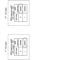
- 6A and 6B show an example of a unified/common TCI framework when a CORESET pool index is configured.
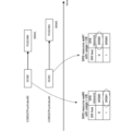
- FIG. 7 shows an example of the challenge of applying the unified/common TCI framework for UL channels/signals or DL reference signals when a CORESET pool index is configured.
- FIG. 8 is a diagram illustrating an example of a method for determining a unified/common TCI state in single DCI-based UL transmission according to the first embodiment.
- FIG. 9 is a diagram illustrating an example of a correspondence relationship between SRS resources (sets) and TCI states according to the first embodiment.
- FIG. 10 is a diagram illustrating another example of the correspondence relationship between the SRS resources (sets) and the TCI states according to the first embodiment.
- FIG. 11 is a diagram illustrating another example of the correspondence relationship between the SRS resources (sets) and the TCI states according to the first embodiment.
- FIG. 12 is a diagram illustrating an example of a method for determining a unified/common TCI state when a CORESET pool index is set according to the second embodiment.
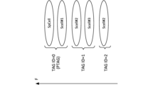
- FIG. 13 is a diagram showing an example of a timing advance group (TAG) to which cells included in a cell group belong.
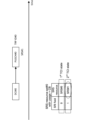
- Figure 14 shows an example of a MAC CE for a timing advance command.
- FIG. 15 is a diagram illustrating an example of a method for determining a unified/common TCI state and a TAG when a CORESET pool index according to the third embodiment is set.
- FIG. 16 is a diagram illustrating an example of a method for determining an SRS resource in UL transmission (eg, PUSCH transmission) according to the fourth embodiment.
- FIG. 17 is a diagram illustrating another example of a method for determining an SRS resource in UL transmission (eg, PUSCH transmission) according to the fourth embodiment.
- FIG. 18 is a diagram illustrating another example of a method for determining an SRS resource in UL transmission (eg, PUSCH transmission) according to the fourth embodiment.
- 19A and 19B are diagrams showing examples of joint ACK/NACK feedback and separate ACK/NACK feedback, respectively.
- FIG. 20 is a diagram illustrating an example of a method for setting a PUCCH resource according to the fourth embodiment.
- FIG. 21 is a diagram showing another example of the method of setting a PUCCH resource according to the fourth embodiment.
- FIG. 22 is a diagram showing another example of the method of setting PUCCH resources according to the fourth embodiment.
- FIG. 23 is a diagram showing another example of the method of setting PUCCH resources according to the fourth embodiment.
- FIG. 20 is a diagram illustrating an example of a method for setting a PUCCH resource according to the fourth embodiment.
- FIG. 21 is a diagram showing another example of the method of setting a PUCCH resource according to the fourth embodiment.
- FIG. 22 is a
- FIG. 24 is a diagram showing another example of the method of configuring PUCCH resources according to the fourth embodiment.
- FIG. 25 is a diagram showing another example of the method of setting PUCCH resources according to the fourth embodiment.
- FIG. 26 is a diagram illustrating an example of a schematic configuration of a wireless communication system according to an embodiment.
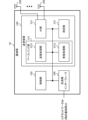
- FIG. 27 is a diagram illustrating an example of the configuration of a base station according to an embodiment.
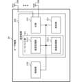
- FIG. 28 is a diagram illustrating an example of the configuration of a user terminal according to an embodiment.
- FIG. 29 is a diagram illustrating an example of the hardware configuration of a base station and a user terminal according to an embodiment.
- FIG. 30 is a diagram illustrating an example of a vehicle according to an embodiment.
- TCI transmission configuration indication state
- the TCI state may represent that which applies to the downlink signal/channel.
- the equivalent of the TCI state which applies to the uplink signal/channel may be expressed as a spatial relation.
- TCI state is information about the Quasi-Co-Location (QCL) of signals/channels and may also be called spatial reception parameters, spatial relation information, etc. TCI state may be set in the UE on a per channel or per signal basis.
- QCL Quasi-Co-Location
- QCL is an index that indicates the statistical properties of a signal/channel. For example, if a signal/channel has a QCL relationship with another signal/channel, it may mean that it can be assumed that at least one of the Doppler shift, Doppler spread, average delay, delay spread, and spatial parameters (e.g., spatial Rx parameters) is identical between these different signals/channels (i.e., it is QCL with respect to at least one of these).
- spatial parameters e.g., spatial Rx parameters
- the spatial reception parameters may correspond to a reception beam (e.g., a reception analog beam) of the UE, and the beam may be identified based on a spatial QCL.
- the QCL (or at least one element of the QCL) in this disclosure may be interpreted as sQCL (spatial QCL).
- QCL types Multiple types of QCLs (QCL types) may be defined. For example, four QCL types A-D may be provided, each of which has different parameters (or parameter sets) that can be assumed to be the same.
- the UE's assumption that a Control Resource Set (CORESET), channel or reference signal is in a particular QCL (e.g., QCL type D) relationship with another CORESET, channel or reference signal may be referred to as a QCL assumption.
- CORESET Control Resource Set
- QCL QCL type D
- the UE may determine at least one of a transmit beam (Tx beam) and a receive beam (Rx beam) for a signal/channel based on the TCI condition or QCL assumption of the signal/channel.
- Tx beam transmit beam
- Rx beam receive beam
- the TCI state may be, for example, information regarding the QCL between the target channel (in other words, the reference signal (RS) for that channel) and another signal (e.g., another RS).
- the TCI state may be set (indicated) by higher layer signaling, physical layer signaling, or a combination of these.
- the physical layer signaling may be, for example, Downlink Control Information (DCI).
- DCI Downlink Control Information
- the channel for which the TCI state or spatial relationship is set (specified) may be, for example, at least one of the following: a downlink shared channel (Physical Downlink Shared Channel (PDSCH)), a downlink control channel (Physical Downlink Control Channel (PDCCH)), an uplink shared channel (Physical Uplink Shared Channel (PUSCH)), and an uplink control channel (Physical Uplink Control Channel (PUCCH)).
- PDSCH Physical Downlink Shared Channel
- PDCCH Physical Downlink Control Channel
- PUSCH Physical Uplink Shared Channel
- PUCCH Physical Uplink Control Channel
- the RS that has a QCL relationship with the channel may be, for example, at least one of a synchronization signal block (SSB), a channel state information reference signal (CSI-RS), a sounding reference signal (SRS), a tracking CSI-RS (also called a tracking reference signal (TRS)), and a QCL detection reference signal (also called a QRS).
- SSB synchronization signal block
- CSI-RS channel state information reference signal
- SRS sounding reference signal
- TRS tracking CSI-RS
- QRS QCL detection reference signal
- An SSB is a signal block that includes at least one of a Primary Synchronization Signal (PSS), a Secondary Synchronization Signal (SSS), and a Physical Broadcast Channel (PBCH).
- PSS Primary Synchronization Signal
- SSS Secondary Synchronization Signal
- PBCH Physical Broadcast Channel
- An SSB may also be referred to as an SS/PBCH block.
- An RS of QCL type X in a TCI state may refer to an RS that has a QCL type X relationship with a certain channel/signal (DMRS), and this RS may be called a QCL source of QCL type X in that TCI state.
- DMRS channel/signal
- a UE can configure a list of up to M TCI-State settings in the higher layer parameter PDSCH-Config for decoding of PDSCH according to a detected PDCCH with DCI intended for the UE and a given serving cell, where M depends on the UE capability maxNumberConfiguredTCIstatesPerCC.
- Each TCI-State includes parameters for setting the QCL relationship between one or two downlink reference signals and the DMRS port of the PDSCH, the DMRS port of the PDCCH, or the CSI-RS port of the CSI-RS resource.
- the QCL relationship is set by the higher layer parameters qcl-Type1 for the first DL RS and qcl-Type2 for the second DL RS (if configured).
- the QCL type corresponding to each DL RS is given by the higher layer parameter qcl-Type in QCL-Info and can take one of the following values: - 'typeA': ⁇ Doppler shift, Doppler spread, average delay, delay spread ⁇ - 'typeB': ⁇ Doppler shift, Doppler spread ⁇ - 'typeC': ⁇ Doppler shift, average delay ⁇ - 'typeD': ⁇ Spatial Rx parameter ⁇
- a TCI-State associates one or two DL Reference Signals (RS) with a corresponding QCL type. If an additional physical cell identifier (PCI) is configured for that RS, it is set to the same value for both DL RSs.
- PCI physical cell identifier
- the PDSCH may be scheduled in a DCI with a TCI field.
- the TCI state for the PDSCH is indicated by the TCI field.
- the TCI field of DCI format 1_1 is 3 bits, and the TCI field of DCI format 1_2 is up to 3 bits.
- the UE In RRC connected mode, if the TCI information element in the first DCI (higher layer parameter tci-PresentInDCI) is set to "enabled" for a CORESET that schedules a PDSCH, the UE assumes that the TCI field is present in DCI format 1_1 of the PDCCH transmitted in that CORESET.
- the TCI information element in the first DCI higher layer parameter tci-PresentInDCI
- the UE assumes that a TCI field with the DCI field size indicated in the TCI information element in the second DCI is present in DCI format 1_2 of the PDSCH transmitted in that CORESET.
- PDSCH may be scheduled with a DCI without a TCI field.
- the DCI format of the DCI may be DCI format 1_0 or DCI format 1_1/1_2 in case the TCI information element in the DCI (higher layer parameters tci-PresentInDCI or tci-PresentInDCI-1-2) is not set (enabled).
- the UE assumes that the TCI state or QCL assumption for the PDSCH is the same as the TCI state or QCL assumption (default TCI state) of the CORESET (e.g., scheduling DCI).
- the TCI state of the PDSCH (default TCI state) may be the TCI state of the lowest CORESET ID in the latest slot in the active DL BWP of that CC (of the particular UL signal). Otherwise, the TCI state of the PDSCH (default TCI state) may be the TCI state of the lowest TCI state ID of the PDSCH in the active DL BWP of the scheduled CC.
- At least one of the MAC CE for activation/deactivation of the PUCCH spatial relationship and the MAC CE for activation/deactivation of the SRS spatial relationship may not be used.
- the default assumptions of the spatial relationship and the PL-RS for the PUCCH are applied. If neither the spatial relationship nor the PL-RS for the SRS (SRS resource for the SRS, or SRS resource corresponding to the SRI in DCI format 0_1 that schedules the PUSCH) is configured in FR2 (applicable condition, second condition), the default assumptions of the spatial relationship and the PL-RS for the PUSCH and the SRS scheduled by DCI format 0_1 (default spatial relationship and default PL-RS) are applied.
- the default spatial relationship and default PL-RS may be the TCI state or QCL assumption of the CORESET with the lowest CORESET ID in that active DL BWP. If a CORESET is not configured in the active DL BWP on that CC, the default spatial relationship and default PL-RS may be the active TCI state with the lowest ID of the PDSCH in that active DL BWP.
- the spatial relationship of PUCCH scheduled by DCI format 0_0 follows the spatial relationship of the PUCCH resource with the lowest PUCCH resource ID among the active spatial relationships of PUCCH on the same CC.
- the network needs to update the PUCCH spatial relationship on all SCells even if no PUCCH is transmitted on the SCell.
- PUCCH configuration is not required for PUSCH scheduled by DCI format 0_0. If there is no active PUCCH spatial relationship or no PUCCH resources on the active UL BWP in a CC for PUSCH scheduled by DCI format 0_0 (applicable condition, second condition), the default spatial relationship and default PL-RS are applied to the PUSCH.
- the conditions for applying the default spatial relationship/default PL-RS for SRS may include setting the default beam path loss enable information element for SRS (upper layer parameter enableDefaultBeamPlForSRS) to be enabled.
- the conditions for applying the default spatial relationship/default PL-RS for PUCCH may include setting the default beam path loss enable information element for PUCCH (upper layer parameter enableDefaultBeamPlForPUCCH) to be enabled.
- the conditions for applying the default spatial relationship/default PL-RS for PUSCH scheduled by DCI format 0_0 may include setting the default beam path loss enable information element for PUSCH scheduled by DCI format 0_0 (upper layer parameter enableDefaultBeamPlForPUSCH0_0) to be enabled.
- the UE applies the default spatial relationship/PL-RS.
- the above threshold may be referred to as time duration for QCL, “timeDurationForQCL”, “Threshold”, “Threshold for offset between a DCI indicating a TCI state and a PDSCH scheduled by the DCI”, “Threshold-Sched-Offset”, “beamSwitchTiming”, schedule offset threshold, scheduling offset threshold, etc.
- the above threshold may be reported by the UE as UE capability (per subcarrier interval).
- the UE assumes that the DMRS port of the PDSCH or PDSCH transmission occasion of the serving cell is QCL-co-located (quasi co-located) with the RS for QCL parameters associated with the two TCI states corresponding to the lowest code point among the TCI code points containing two different TCI states (two default QCL assumption decision rule).
- the 2 default TCI enable information element indicates that Rel. 16 operation of the 2 default TCI states for the PDSCH is enabled when at least one TCI codepoint is mapped to the 2 T
- the default TCI state for PDSCH in Rel. 15/16 is specified as a default TCI state for a single TRP, a default TCI state for multiple TRPs based on multiple DCIs, and a default TCI state for multiple TRPs based on a single DCI.
- the default TCI state for aperiodic CSI-RS (A (aperiodic)-CSI-RS) is specified as follows: default TCI state for single TRP, default TCI state for multi-TRP based on multi-DCI, and default TCI state for multi-TRP based on single DCI.
- the unified TCI framework does not specify the TCI state or spatial relationship for each channel as in Rel. 15, but instead specifies a common beam (common TCI state) and may apply it to all UL and DL channels, or a common beam for UL may apply to all UL channels and a common beam for DL may apply to all DL channels.
- a common beam common TCI state
- One common beam for both DL and UL, or one common beam for DL and one common beam for UL (total of two common beams) are being considered.
- the UE may assume the same TCI state for UL and DL (joint TCI state, joint TCI pool, joint common TCI pool, joint TCI state set).
- the UE may assume different TCI states for UL and DL (separate TCI state, separate TCI pool, UL separate TCI pool and DL separate TCI pool, separate common TCI pool, UL common TCI pool and DL common TCI pool).
- the joint TCI state or separate TCI state to be applied may be configured (or switched) by the RRC/MAC CE.
- the UL and DL default beams may be aligned via MAC CE based beam management (MAC CE level beam instructions).
- the PDSCH default TCI state may be updated to match the default UL beam (spatial relationship).
- DCI based beam management may indicate a common beam/unified TCI state from the same TCI pool (joint common TCI pool, joint TCI pool, set) for both UL and DL.
- X (>1) TCI states may be activated by the MAC CE.
- the UL/DL DCI may select one out of the X active TCI states.
- the selected TCI state may be applied to both UL and DL channels/RS.
- the TCI pool (set) may be multiple TCI states set by RRC parameters, or multiple TCI states (active TCI states, active TCI pool, set) activated by the MAC CE among multiple TCI states set by RRC parameters.
- Each TCI state may be a QCL type A/D RS.
- SSB, CSI-RS, or SRS may be set as the QCL type A/D RS.
- the number of TCI states corresponding to each of one or more TRPs may be specified.
- the number N ( ⁇ 1) of TCI states (UL TCI states) applied to UL channels/RS and the number M ( ⁇ 1) of TCI states (DL TCI states) applied to DL channels/RS may be specified.
- At least one of N and M may be notified/configured/instructed to the UE via higher layer signaling/physical layer signaling.
- this may mean that one UL TCI state and one DL TCI state for a single TRP are notified/configured/instructed separately to the UE (separate TCI states for a single TRP).
- this may mean that multiple (two) UL TCI states and multiple (two) DL TCI states for multiple (two) TRPs are notified/configured/instructed to the UE (separate TCI states for multiple TRPs).
- N and M are 1 or 2, but the values of N and M may be 3 or more, and N and M may be different.
- it may be supported to indicate one common beam (e.g., a common beam) by RRC/MAC CE/DCI, and the one common beam may be applied to multiple DL/UL channels/reference signals.
- FIG. 1A and 1B show an example of a unified TCI framework.
- FIG. 1A shows an example of a joint DL/UL TCI state
- FIG. 1B shows an example of a separate TCI state.
- RRC parameters configure multiple TCI states for both DL and UL.
- the TCI states configured by the RRC parameters may be referred to as configured TCI states or configured TCI states.
- the MAC CE may activate multiple TCI states of the configured TCI states.
- the DCI may indicate one of the activated TCI states.
- the TCI state indicated by the DCI may be referred to as indicated TCI state or indicated TCI state.
- the DCI may be a UL DCI (e.g., a DCI used for scheduling PUSCH) or a DL DCI (e.g., a DCI used for scheduling PDSCH).
- the indicated TCI state may apply to at least one (or all) of the UL/DL channels/RS.
- One DCI may indicate both UL TCI and DL TCI.
- a point may be one TCI state that applies to both UL and DL, or it may be two TCI states that apply to UL and DL, respectively.
- At least one of the multiple TCI states configured by the RRC parameters and the multiple TCI states activated by the MAC CE may be referred to as a TCI pool (common TCI pool, joint TCI pool, TCI state pool).
- the multiple TCI states activated by the MAC CE may be referred to as an active TCI pool (active common TCI pool).
- the higher layer parameters (RRC parameters) that set multiple TCI states may be referred to as configuration information that sets multiple TCI states, or simply as “configuration information.” Also, in this disclosure, being instructed to set one of multiple TCI states using DCI may mean receiving indication information that indicates one of the multiple TCI states included in DCI, or may simply mean receiving "instruction information.”
- the RRC parameters configure multiple TCI states for both DL and UL (joint common TCI pool).
- the MAC CE may activate multiple TCI states (active TCI pools) out of the configured multiple TCI states. Separate active TCI pools for each of UL and DL may be configured/activated.
- the DL DCI or new DCI format may select (indicate) one or more (e.g., one) TCI states.
- the selected TCI state may apply to one or more (or all) DL channels/RS.
- the DL channels may be PDCCH/PDSCH/CSI-RS.
- the UE may determine the TCI state of each DL channel/RS using the TCI state behavior (TCI framework) of Rel. 16.
- the UL DCI or new DCI format may select (indicate) one or more (e.g., one) TCI states.
- the selected TCI state may apply to one or more (or all) UL channels/RS.
- the UL channels may be PUSCH/SRS/PUCCH. In this way, different DCIs may indicate UL TCI and DL DCI separately.
- the MAC CE/DCI will support beam activation/indication to a TCI state associated with a different physical cell identifier (PCI). Also, in Rel. 18 NR and later, it is assumed that the MAC CE/DCI will support indicative serving cell change to a cell with a different PCI.
- PCI physical cell identifier
- the method of setting/indicating the TCI state in FIG. 1A e.g., joint DL/UL TCI state
- the method of setting/indicating the application of the TCI state in FIG. 1B may be switched and applied. Whether the joint DL/UL TCI state or the separate TCI state is applied may be set by the base station to the UE by a higher layer parameter.
- Unified TCI Framework supports the following modes 1 to 3: [Mode 1] MAC CE based TCI state indication [Mode 2] DCI based TCI state indication by DCI format 1_1/1_2 with DL assignment [Mode 3] DCI based TCI state indication by DCI format 1_1/1_2 without DL assignment
- TCI State ID receives DCI format 1_1/1_2 providing indicated TCI state with Rel.
- DCI format 1_1/1_2 may or may not be accompanied by DL assignment if one is available.
- DCI format 1_1/1_2 does not carry a DL assignment
- the UE can assume (verify) the following for that DCI: -
- the CS-RNTI is used to scramble the CRC for the DCI.
- the values of the following DCI fields are set as follows: -
- the redundancy version (RV) field is all '1's.
- the modulation and coding scheme (MCS) field is all '1's.
- NDI new data indicator
- the frequency domain resource assignment (FDRA) field is all '0's for FDRA type 0 or all '1's for FDRA type 1 or all '0's for Dynamic Switch (similar to PDCCH validation for release of DL semi-persistent scheduling (SPS) or UL grant type 2 scheduling).
- DCI in the above Mode 2/Mode 3 may be called beam instruction DCI.
- Rel. 15/16 if the UE does not support active BWP change via DCI, the UE will ignore the BWP indicator field.
- a similar behavior is considered for the relationship between Rel. 17 TCI state support and the interpretation of the TCI field. If the UE is configured with Rel. 17 TCI state, the TCI field will always be present in DCI format 1_1/1_2, and if the UE does not support TCI update via DCI, the UE will ignore the TCI field.
- the presence or absence of a TCI field (TCI presence information in DCI, tci-PresentInDCI) is set for each CORESET.
- the TCI field in DCI format 1_1 is 0 bits if the higher layer parameter tci-PresentInDCI is not enabled, and 3 bits otherwise. If the BWP indicator field indicates a BWP other than the active BWP, the UE shall follow the following actions: [Operation] If the higher layer parameter tci-PresentInDCI is not enabled for the CORESET used for the PDCCH carrying that DCI format 1_1, the UE shall assume that tci-PresentInDCI is not enabled for all CORESETs in the indicated BWP, otherwise the UE shall assume that tci-PresentInDCI is enabled for all CORESETs in the indicated BWP.
- the TCI field in DCI format 1_2 is 0 bit if the higher layer parameter tci-PresentInDCI-1-2 is not set, otherwise it is 1, 2 or 3 bits determined by the higher layer parameter tci-PresentInDCI-1-2. If the BWP indicator field indicates a BWP other than the active BWP, the UE shall follow the following actions.
- the UE shall assume that tci-PresentInDCI is not enabled for all CORESETs in the indicated BWP, otherwise the UE shall assume that tci-PresentInDCI-1-2 for all CORESETs in the indicated BWP is set with the same value as tci-PresentInDCI-1-2 set for the CORESET used for the PDCCH carrying that DCI format 1_2.
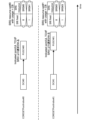
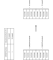
- Figure 2A shows an example of a DCI-based joint DL/UL TCI status indication.
- a TCI status ID indicating the joint DL/UL TCI status is associated with the value of the TCI field for the joint DL/UL TCI status indication.
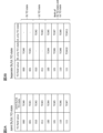
- FIG. 2B shows an example of a DCI-based separate DL/UL TCI status indication.
- At least one TCI status ID is associated with the value of the TCI field for the separate DL/UL TCI status indication: a TCI status ID indicating a DL-only TCI status and a TCI status ID indicating a UL-only TCI status.
- TCI field values 000 to 001 are associated with only one TCI status ID for DL
- TCI field values 010 to 011 are associated with only one TCI status ID for UL
- TCI field values 100 to 111 are associated with both one TCI status ID for DL and one TCI status ID for UL.
- the unified/common TCI state may mean the Rel. 17 TCI state indicated using (Rel. 17) DCI/MAC CE/RRC (indicated Rel. 17 TCI state).
- indicated Rel. 17 TCI state, indicated TCI state, indicated joint TCI state, unified/common TCI state, TCI state applicable to multiple types of signals (channels/RS), and TCI state for multiple types of signals (channels/RS) may be interpreted as interchangeable.
- the indicated Rel. 17 TCI state may be shared with at least one of the UE-specific reception on PDSCH/PDCC (updated using Rel. 17 DCI/MAC CE/RRC), PUSCH of dynamic grant (DCI)/configured grant, and multiple (e.g., all) dedicated PUCCH resources.
- the TCI state indicated by the DCI/MAC CE/RRC may be referred to as the indicated TCI state, the unified TCI state.
- a TCI state other than the unified TCI state may refer to a Rel. 17 TCI state configured using the (Rel. 17) MAC CE/RRC (configured Rel. 17 TCI state).
- the configured Rel. 17 TCI state, configured TCI state, configured joint TCI state, a TCI state other than the unified TCI state, and a TCI state applied to a specific type of signal (channel/RS) may be interpreted as being mutually interchangeable.
- the configured Rel. 17 TCI state may not be shared with at least one of the UE-specific reception in the PDSCH/PDCC (updated using Rel. 17 DCI/MAC CE/RRC), the PUSCH of the dynamic grant (DCI)/configured grant, and multiple (e.g., all) dedicated PUCCH resources.
- the configured Rel. 17 TCI state may be configured by the RRC/MAC CE for each CORESET/resource/resource set, and may not be updated even if the indicated Rel. 17 TCI state (common TCI state) described above is updated.
- the indicated Rel. 17 TCI state will be applied to UE-specific channels/signals (RS). It is also being considered that the UE will be notified using higher layer signaling (RRC signaling) as to whether the indicated Rel. 17 TCI state or the configured Rel. 17 TCI state will be applied to non-UE-specific channels/signals.
- RS UE-specific channels/signals
- RRC signaling higher layer signaling
- the RRC parameters for the configured Rel. 17 TCI state (TCI state ID) will have the same configuration as the RRC parameters for the TCI state in Rel. 15/16. It is being considered that the configured Rel. 17 TCI state will be configured/instructed for each CORESET/resource/resource set using RRC/MAC CE. It is also being considered that the UE will make decisions regarding the configuration/instruction based on specific parameters.
- the UE will update the indicated TCI state and the configured TCI state separately. For example, if the unified TCI state for the indicated TCI state is updated for the UE, the configured TCI state may not need to be updated. It is also being considered that the UE will make a decision about the update based on a specific parameter.
- RRC/MAC CE higher layer signaling
- TCI state indication for intra-cell beam indication (TCI state indication), it is being considered to support Rel. 17 TCI state indication for UE-specific CORESET and PDSCH associated with that CORESET, and non-UE-specific CORESET and PDSCH associated with that CORESET.
- inter-cell beam indication e.g., L1/L2 inter-cell mobility
- support for indicating Rel. 17 TCI states for UE-specific CORESETs and PDSCHs associated with the CORESETs is under consideration.
- the legacy MAC CE/RACH signaling mechanism may be used.
- the CSI-RS related to the Rel. 17 TCI state applied to CORESET#0 may be QCL'd with the SSB related to the serving cell PCI (physical cell ID) (similar to Rel. 15).
- CORESETs with common search space (CSS), and CORESETs with CSS and UE-specific search space (USS), whether to follow the indicated Rel. 17 TCI state may be configured for each CORESET by RRC parameters. If the indicated Rel. 17 TCI state is not configured for that CORESET, the configured Rel. 17 TCI state may be applied to that CORESET.
- RRC parameters may be configured for each channel/resource/resource set to follow or not follow the indicated Rel. 17 TCI state. If the indicated Rel. 17 TCI state is not configured for that channel/resource/resource set, the configured Rel. 17 TCI state may be applied to that channel/resource/resource set.
- the indicated TCI state by the MAC CE/DCI may apply to the following channels/RS:
- CORESET0 follows the TCI state activated by the MAC CE or is QCL'd with SSB.
- the indicated TCI state For a CORESET with index other than 0 with USS/CSS type 3, the indicated TCI state always applies.
- the indicated TCI state applies. Otherwise, the configured TCI state for that CORESET applies to that CORESET.
- [PDSCH] - The indicated TCI state always applies for all UE-dedicated PDSCHs.
- a non-UE-dedicated PDSCH PDSCH scheduled by a DCI in the CSS
- followUnifiedTCIState is set (for the CORESET of the PDCCH that schedules the PDSCH)
- the indicated TCI state may apply. Otherwise, the configured TCI state for the PDSCH applies to the PDSCH.
- followUnifiedTCIState is not set for a PDSCH, whether a non-UE-dedicated PDSCH follows the indicated TCI state may depend on whether followUnifiedTCIState is set for the CORESET used to schedule the PDSCH.
- CSI-RS For an A-CSI-RS for CSI acquisition or beam management, if followUnifiedTCIState is set (for the CORESET of the PDCCH that triggers that A-CSI-RS), the indicated TCI state applies. For other CSI-RSs, the configured TCI state for that CSI-RS applies.
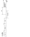
- beam application time (BAT) In the DCI-based beam indication in Rel. 17, the following considerations 1 and 2 are considered regarding the application time of the indication of the beam/unified TCI state (beam application time (BAT) condition).
- the first slot to apply the indicated TCI is at least Y symbols after the last symbol of the acknowledgement (ACK) for the joint or separate DL/UL beam indication. It is contemplated that the first slot to apply the indicated TCI is at least Y symbols after the last symbol of the ACK/negative acknowledgement (NACK) for the joint or separate DL/UL beam indication.
- Y symbols may be set by the base station based on the UE capabilities reported by the UE. The UE capabilities may be reported on a symbol-by-symbol basis.
- the ACK may be an ACK for a PDSCH scheduled by the beam instruction DCI.
- the PDSCH may not be transmitted.
- the ACK may be an ACK for the beam instruction DCI.
- the value of the Y symbol will also be different, so the application time may differ between multiple CCs.
- the application timing/BAT of the beam instruction may follow any of the following options 1 to 3.
- [Option 1] Both the first slot and the Y symbol are determined on the carrier with the smallest SCS among the one or more carriers to which the beam direction applies.
- [Option 2] Both the first slot and the Y symbol are determined on the carrier with the smallest SCS among the one or more carriers to which the beam direction applies and the UL carrier carrying the ACK.
- [Option 3] Both the first slot and the Y symbol are determined on the UL carrier that carries the ACK.
- the application time (Y symbols) of beam direction for CA may be determined on the carrier with the smallest SCS among the carriers to which beam direction applies.
- Rel. 17 MAC CE based beam direction (when only a single TCI codepoint is activated) may follow the Rel. 16 application timeline for MAC CE activation.
- the indicated TCI state with Rel. 17 TCI state may start to apply from the first slot that is at least Y symbols after the last symbol of the PUCCH, where Y may be a higher layer parameter (e.g., BeamAppTime_r17[symbols]). Both the first slot and Y symbols may be determined on the carrier with the smallest SCS among the carriers for which the beam indication applies.
- the UE may assume one indicated TCI state with Rel17 TCI state for DL and UL, or one indicated TCI state with Rel17 TCI state for UL (separate from DL) at a given time.
- X [ms] may be used instead of Y [symbol].
- the UE reports at least one of the following UE capabilities 1 and 2.
- UE Capability 1 Minimum application time per SCS (minimum of Y symbols between the last symbol of the PUCCH carrying ACK and the first slot in which the beam is applied).
- UE Capability 2 Minimum time gap between the last symbol of the beam instruction PDCCH (DCI) and the first slot where the beam is applied. The gap between the last symbol of the beam instruction PDCCH (DCI) and the first slot where the beam is applied may meet the UE capability (minimum time gap).
- UE capability 2 may be an existing UE capability (e.g., timeDurationForQCL).
- the relationship between the beam instruction and the channel/RS to which the beam is applied may satisfy at least one of UE capabilities 1 and 2.
- the parameters set by the base station regarding the application time may be optional fields.
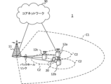
- Multi-TRP In NR, one or more transmission/reception points (TRPs) (multi-TRPs) are considered to perform DL transmission to a UE using one or more panels (multi-panels). It is also considered that a UE performs UL transmission to one or more TRPs.
- TRPs transmission/reception points
- multiple TRPs may correspond to the same cell identifier (cell identifier (ID)) or different cell IDs.
- the cell ID may be a physical cell ID (e.g., PCI) or a virtual cell ID.
- FIGS 4A-4D show examples of multi-TRP scenarios. In these examples, we assume that each TRP is capable of transmitting four different beams, but this is not limited to this example.
- FIG. 4A shows an example of a case where only one TRP (TRP1 in this example) of the multi-TRP transmits to the UE (which may be called single mode, single TRP, etc.).
- TRP1 transmits both a control signal (PDCCH) and a data signal (PDSCH) to the UE.
- PDCCH control signal
- PDSCH data signal
- single TRP mode may refer to the mode when multi-TRP (mode) is not set.
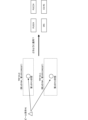
- FIG 4B shows an example of a case where only one TRP (TRP1 in this example) of the multi-TRP transmits a control signal to the UE, and the multi-TRP transmits a data signal (which may be called a single master mode).
- the UE receives each PDSCH transmitted from the multi-TRP based on one Downlink Control Information (DCI).
- DCI Downlink Control Information
- FIG. 4C shows an example of a case where each of the multi-TRPs transmits a part of a control signal to the UE and the multi-TRP transmits a data signal (which may be called a master-slave mode).
- TRP1 may transmit part 1 of the control signal (DCI) and TRP2 may transmit part 2 of the control signal (DCI).
- Part 2 of the control signal may depend on part 1.
- the UE receives each PDSCH transmitted from the multi-TRP based on these parts of DCI.
- FIG. 4D shows an example of a case where each of the multi-TRPs transmits a separate control signal to the UE, and the multi-TRP transmits a data signal (which may be called a multi-master mode).
- a first control signal (DCI) may be transmitted from TRP1
- a second control signal (DCI) may be transmitted from TRP2.
- the UE receives each PDSCH transmitted from the multi-TRP based on these DCIs.
- the DCI may be called a single DCI (S-DCI, single PDCCH). Also, when multiple PDSCHs from a multi-TRP such as that shown in FIG. 4D are scheduled using multiple DCIs, these multiple DCIs may be called multiple DCIs (M-DCI, multiple PDCCHs).
- Each TRP in a multi-TRP may transmit a different Transport Block (TB)/Code Word (CW)/different layer.
- TB Transport Block
- CW Code Word
- each TRP in a multi-TRP may transmit the same TB/CW/layer.
- Non-Coherent Joint Transmission is being considered as one form of multi-TRP transmission.
- TRP1 modulates and maps a first codeword, and transmits a first PDSCH using a first number of layers (e.g., two layers) and a first precoding by layer mapping.
- TRP2 modulates and maps a second codeword, and transmits a second PDSCH using a second number of layers (e.g., two layers) and a second precoding by layer mapping.
- multiple PDSCHs (multi-PDSCHs) that are NCJTed may be defined as partially or completely overlapping with respect to at least one of the time and frequency domains.
- the first PDSCH from the first TRP and the second PDSCH from the second TRP may overlap with each other in at least one of the time and frequency resources.
- the first PDSCH and the second PDSCH may be assumed to be not quasi-co-located (QCL). Reception of multiple PDSCHs may be interpreted as simultaneous reception of PDSCHs that are not of a certain QCL type (e.g., QCL type D).
- QCL type D e.g., QCL type D
- PDSCH transport block (TB) or codeword (CW) repetition across multi-TRP is supported. It is considered that repetition methods (URLLC schemes, e.g., schemes 1, 2a, 2b, 3, 4) across multi-TRP in the frequency domain, layer (spatial) domain, or time domain are supported.
- URLLC schemes e.g., schemes 1, 2a, 2b, 3, 4
- multi-PDSCH from multi-TRP is space division multiplexed (SDM).
- SDM space division multiplexed
- FDM frequency division multiplexed
- RV redundancy version
- the RV may be the same or different for multi-TRP.
- multiple PDSCHs from multiple TRPs are time division multiplexed (TDM).
- TDM time division multiplexed
- multiple PDSCHs from multiple TRPs are transmitted in one slot.
- multiple PDSCHs from multiple TRPs are transmitted in different slots.
- Such a multi-TRP scenario allows for more flexible transmission control using channels with better quality.
- NCJT using multiple TRPs/panels may use high rank.
- both single DCI single PDCCH, e.g., FIG. 4B
- multiple DCI multiple PDCCH, e.g., FIG. 4D
- the maximum number of TRPs may be 2.
- TCI extension For single PDCCH design (mainly for ideal backhaul), TCI extension is being considered.
- Each TCI code point in the DCI may correspond to TCI state 1 or 2.
- the TCI field size may be the same as that of Rel. 15.
- one TCI state without CORESETPoolIndex (also called TRP Info) is set for one CORESET.
- a CORESET pool index is set for each CORESET.
- Multi-TRP beam direction It is assumed that the following two mechanisms (e.g., beam directing method 1/beam directing method 2) will be supported for beam directing for multi-TRP.
- the UE may receive a beam indication (e.g., DCI) and may determine/assess multiple TCI states (corresponding to one or more respective TRPs) based on the TCI field included in the beam indication.
- a beam indication e.g., DCI
- TCI states corresponding to one or more respective TRPs
- Beam directing method 1 can be suitably applied in an ideal backhaul environment. Beam directing method 1 may be suitably applied, for example, in single DCI-based transmission.
- a minimum BAT may be specified in a non-ideal backhaul environment (e.g., multi-DCI based transmission).
- an additional BAT corresponding to at least one of the multiple TRPs may be specified in a non-ideal backhaul environment (e.g., multi-DCI based transmission).
- FIG. 5A illustrates an example of beam indication method 1.
- a UE receives one beam indication.
- the one beam indication may indicate two TCI states (a first TCI state and a second TCI state).
- the UE determines the first TCI state and the second TCI state based on one or more TCI fields included in the one beam indication.
- the first TCI state may correspond to a first TRP.
- the second TCI state may correspond to a second TRP.
- the UE may receive multiple (e.g., two) beam indications (e.g., DCIs).
- the UE may determine/judge one or more TCI states corresponding to each beam indication based on respective TCI fields included in the multiple beam indications. For example, the UE may determine a first (DL/UL) TCI state based on a first beam indication and a second (DL/UL) TCI state based on a second beam indication.
- the first beam instruction/first TCI state may correspond to the first TRP/first CORESET pool index (e.g., CORESET pool index of a first value (e.g., 0))/first CORESET (1st CORESETs).
- the second beam instruction/second TCI state may correspond to the second TRP/second CORESET pool index (e.g., CORESET pool index of a second value (e.g., 1))/second CORESET (2nd CORESETs).
- Beam directing method 2 can be preferably applied in a non-ideal backhaul environment. Beam directing method 2 may be preferably applied in, for example, multi-DCI-based transmission.
- FIG. 5B is a diagram showing an example of beam instruction method 2.
- the UE receives two beam instructions.
- the UE determines a first TCI state based on a TCI field included in one of the two beam instructions.
- the UE determines a second TCI state based on a TCI field included in the other of the two beam instructions.
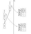
- a TCI state (e.g., an indicated TCI state) is indicated for each TRP (or each CORESET pool index).
- the unified TCI state corresponding to the first TRP is indicated by the RRC parameters/MAC CE/DCI for the first CORESET pool index #0 (see FIG. 6A).
- the unified TCI state corresponding to the second TRP is indicated by the RRC parameters/MAC CE/DCI for the second CORESET pool index #1 (see FIG. 6B).
- the TCI field included in the DCI associated with one CORESET pool index can indicate a joint/DL/UL TCI state specific to the same CORESET pool index value.
- the joint/DL/UL TCI state may mean at least one of the following in the unified TCI framework: a joint TCI state (TCI state that applies to UL and DL), a separate DL TCI state (TCI state that applies only to DL), and a separate UL TCI state (TCI state that applies only to UL).
- single DCI based multi-TRP When single DCI based multi-TRP is supported/applied, if one indication (e.g., single DCI) indicates one or more (e.g., two) indicated joint/DL/UL TCI states (e.g., indicated joint DL/UL TCI state), the question arises as to how to apply the indicated joint/DL/UL TCI state to each channel/reference signal (RS) (see Figure 7).
- one indication e.g., single DCI
- indicates one or more (e.g., two) indicated joint/DL/UL TCI states e.g., indicated joint DL/UL TCI state
- the question arises as to how to apply the indicated joint/DL/UL TCI state to each channel/reference signal (RS) (see Figure 7).
- RS channel/reference signal
- FIG. 7 shows a case where a first indicated TCI state and a second indicated TCI state are indicated by beam indication #1 (e.g., the TCI state field of the DCI).
- the first TCI state may be applied to the first PDSCH (e.g., corresponding to the first TRP)
- the second TCI state may be applied to the second PDSCH (e.g., corresponding to the second TRP).
- TCI state e.g., indication joint TCI state
- other channels/RS e.g., PUSCH/PUCCH/SRS/CSI-RS
- the inventors therefore came up with a method for appropriately performing operations related to the unified TCI state.
- A/B and “at least one of A and B” may be interpreted as interchangeable. Also, in this disclosure, “A/B/C” may mean “at least one of A, B, and C.”
- Radio Resource Control RRC
- RRC parameters RRC parameters
- RRC messages higher layer parameters, fields, information elements (IEs), settings, etc.
- IEs information elements
- CE Medium Access Control
- update commands activation/deactivation commands, etc.
- higher layer signaling may be, for example, Radio Resource Control (RRC) signaling, Medium Access Control (MAC) signaling, broadcast information, or any combination thereof.
- RRC Radio Resource Control
- MAC Medium Access Control
- the MAC signaling may use, for example, a MAC Control Element (MAC CE), a MAC Protocol Data Unit (PDU), etc.
- the broadcast information may be, for example, a Master Information Block (MIB), a System Information Block (SIB), Remaining Minimum System Information (RMSI), Other System Information (OSI), etc.
- MIB Master Information Block
- SIB System Information Block
- RMSI Remaining Minimum System Information
- OSI System Information
- the physical layer signaling may be, for example, Downlink Control Information (DCI), Uplink Control Information (UCI), etc.
- DCI Downlink Control Information
- UCI Uplink Control Information
- index identifier
- indicator indicator
- resource ID etc.
- sequence list, set, group, cluster, subset, etc.
- DMRS nal
- antenna port group e.g., DMRS port group
- group e.g., spatial relationship group, Code Division Multiplexing (CDM) group, reference signal group, CORESET group, Physical Uplink Control Channel (PUCCH) group, PUCCH resource group
- resource e.g., reference signal resource, SRS resource
- resource set e.g., reference signal resource set
- CORESET pool downlink Transmission Configuration Indication state (TCI state) (DL TCI state), uplink TCI state (UL TCI state), unified TCI state, common TCI state, indicated TCI state, quasi-co-location (QCL), QCL assumption, etc.
- TCI state downlink Transmission Configuration Indication state
- DL TCI state DL TCI state
- uplink TCI state UL TCI state
- unified TCI state common TCI state
- indicated TCI state indicated TCI state
- QCL quasi-co-location
- QCL assumption etc.
- the spatial relationship information identifier (ID) (TCI state ID) and the spatial relationship information (TCI state) may be read as interchangeable.
- ID spatial relationship information
- TCI state and TCI may be read as interchangeable.
- the panel identifier (ID) and panel may be read as interchangeable.
- the TRP ID and TRP, the CORESET group ID and CORESET group, etc. may be read as interchangeable.
- TRP transmission point
- panel DMRS port group
- CORESET pool one of two TCI states associated with one code point in the TCI field
- the transmission/reception of a channel/signal using a single TRP may be interpreted as the TCI states (joint/separate/indicative TCI states) being equal in the transmission/reception of that channel/signal (e.g., NCJT/CJT/repeat), or the number of TCI states (joint/separate/indicative TCI states) being one in the transmission/reception of that channel/signal (e.g., NCJT/CJT/repeat).
- Transmission/reception of a channel/signal using a single TRP may be interpreted as the TCI states (joint/separate/indicated TCI states) being different in the transmission/reception of the channel/signal (e.g., NCJT/CJT/repeat), or the number of different TCI states (joint/separate/indicated TCI states) being multiple (e.g., two) in the transmission/reception of the channel/signal (e.g., NCJT/CJT/repeat).
- single TRP, single TRP system, single TRP transmission, and single PDSCH may be read as interchangeable.
- multi-TRP, multi-TRP system, multi-TRP transmission, and multi-PDSCH may be read as interchangeable.
- a single DCI, a single PDCCH, multiple TRP based on a single DCI, activating two TCI states on at least one TCI code point, mapping at least one code point of a TCI field to two TCI states, and setting a specific index (e.g., a TRP index, a CORESET pool index, or an index corresponding to a TRP) for a specific channel/CORESET may be interpreted as interchangeable.
- a single TRP, a channel/signal using a single TRP, a channel using one TCI state/spatial relationship, multi-TRP not being enabled by RRC/DCI, multiple TCI states/spatial relationships not being enabled by RRC/DCI, a CORESETPoolIndex value of 1 not being set for any CORESET, and no code point in the TCI field being mapped to two TCI states may be read as interchangeable.
- multi-TRP channel/signal using multi-TRP, channel using multiple TCI states/spatial relationships, multi-TRP enabled by RRC/DCI, multiple TCI states/spatial relationships enabled by RRC/DCI, and at least one of multi-TRP based on a single DCI and multi-TRP based on multiple DCI may be read as interchangeable.
- multi-TRP based on multi-DCI setting one CORESET pool index (CORESETPoolIndex) value for a CORESET
- multiple specific indexes e.g., TRP indexes, CORESET pool indexes, or indexes corresponding to TRPs
- TRP#2 (second TRP)
- single DCI sDCI
- single PDCCH multi-TRP system based on single DCI
- sDCI-based MTRP multi-TRP system based on single DCI
- activation of two TCI states on at least one TCI codepoint may be read as interchangeable.
- multi-DCI multi-PDCI
- multi-PDCCH multi-PDCCH
- multi-TRP system based on multi-DCI
- mDCI-based MTRP two CORESET pool indices
- beam instruction DCI, beam instruction MAC CE, and beam instruction DCI/MAC CE may be interpreted as interchangeable.
- an instruction regarding the instruction TCI state to the UE may be given using at least one of DCI and MAC CE.
- channel, signal, and channel/signal may be read as interchangeable.
- DL channel, DL signal, DL signal/channel, transmission/reception of DL signal/channel, DL reception, and DL transmission may be read as interchangeable.
- UL channel, UL signal, UL signal/channel, transmission/reception of UL signal/channel, UL reception, and UL transmission may be read as interchangeable.
- applying TCI state/QCL assumptions to each channel/signal/resource may mean applying TCI state/QCL assumptions to transmission and reception of each channel/signal/resource.
- the first TRP may correspond to the first TCI state (the first TCI state indicated).
- the second TRP may correspond to the second TCI state (the second TCI state indicated).
- the nth TRP may correspond to the nth TCI state (the nth TCI state indicated).
- the first CORESET pool index value (e.g., 0), the first TRP index value (e.g., 1), and the first TCI state (first DL/UL (joint/separate) TCI state) may correspond to each other.
- the second CORESET pool index value (e.g., 1), the second TRP index value (e.g., 2), and the second TCI state (second DL/UL (joint/separate) TCI state) may correspond to each other.
- the application of multiple TCI states in transmission and reception using multiple TRPs will be mainly described in terms of a method targeting two TRPs (i.e., when at least one of N and M is 2), but the number of TRPs may be three or more (multiple), and each embodiment may be applied to correspond to the number of TRPs. In other words, at least one of N and M may be a number greater than 2.
- This embodiment may be applied to single DCI-based multi-TRP, which may refer to an operation in which multiple channels/signals are scheduled/triggered/activated by one DCI (e.g., a single DCI).
- a single DCI based multi-TRP may include at least one of PUSCH repetition scheduled by a single DCI (e.g., S-DCI M-TRP PUSCH repetition), PUCCH repetition scheduled/triggered by a single DCI (e.g., S-DCI M-TRP PUCCH repetition), and simultaneous UL transmission using multiple panels based on a single DCI (e.g., S-DCI M-TRP STxMP).
- a single DCI based multi-TRP may include PDSCH/PUSCH/PUCCH/SRS/CSI-RS scheduled/triggered/activated by a single DCI.
- a TRP ID may be defined/notified.
- the TCI state e.g., ⁇ 1st TCI, 2nd TCI ⁇
- information regarding the TRP identifier may be explicitly set/instructed from the base station to the UE by the RRC/MAC CE/DCI.
- the TRP ID may be associated with an implicit ID.
- an SRS resource set e.g., a 1st/2nd SRS resource set
- the TRP may be associated with the TRP.
- one or more (e.g., two) indicated TCI states may be reported depending on the channel/signal. Only one indicated TCI state may be reported for a particular channel/signal.
- this embodiment is not limited to a single DCI-based multi-TRP, but may also be applied to a multi-DCI-based multi-TRP.
- ⁇ Tenth embodiment> an example of notification of a unified TCI state for a single DCI-based multi-TRP is described.
- an explicit TRP ID may be set/indicated for each channel/RS.
- an implicit TRP ID may be set/indicated for each channel/RS.
- Each channel/RS may be interpreted as at least one of PUSCH, PUCCH, SRS, CSI-RS, PDSCH, and PDCCH.
- a TRP ID may be used in a single DCI-based multi-TRP
- a CORESET pool index may be used in a multi-DCI-based multi-TRP.
- a CORESET pool index may be associated with a TRP ID. In this case, the CORESET pool index may be applied in both a single DCI-based multi-TRP and a multi-DCI-based multi-TRP.
- an indicated TCI state (e.g., indicated TCI) is indicated by the RRC/MAC CE/DCI, the UE may apply the indicated TCI state to all channels/RS.
- An indicated TCI state may mean an indicated joint/UL TCI state or an indicated joint/DL TCI state.
- the UE may apply one or both of the two indicated TCI states depending on the TRP ID corresponding to each channel/RS.
- PUSCH UL transmission
- the allocation may be read as mapping/association/linking.
- multiple (e.g., two) indication TCI states may be assigned based on at least one of the following options 1-1 to 1-2.
- TCI states For a PUSCH scheduled/triggered/activated by a single DCI, multiple (eg, two) indication TCI states may be assigned using the RRC/MAC CE.
- a PUSCH scheduled/triggered/activated by a single DCI may be assigned any of a number of indicated TCI states (or one of them may be selected) by the DCI.
- the DCI used to indicate the indicated TCI state and the DCI used to schedule/trigger/activate the PUSCH may be different DCIs or the same DCI.
- Two indication TCI states may be indicated by the DCI based on at least one (or both) of options 1-2-1 and 1-2-2 below.
- Each PUSCH may be transmitted using at least one of the joint/UL TCI state and TPC parameters corresponding to the SRS resource set (or SRS resource) indicated by a predefined rule/higher layer/DCI.
- the association between the SRS resource set (or SRS resource) and the joint/UL TCI state or TPC parameters may be defined in the specifications or may be configured in the UE by the base station using RRC parameters, etc.
- an SRS resource set (or an SRS resource) may be indicated by the SRS resource set indicator field.
- the SRS resource set (or an SRS resource) may be associated with a certain TCI state (or a TRP ID).
- the SRS resource set indication field may be present in DCI format 0_1/0_2.
- PUSCH may be scheduled/triggered/activated by DCI that includes the SRS resource set indication field.
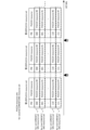
- Figure 8 shows an example of a case where two SRS resource sets (here, SRS resource sets #0/#1) are indicated.
- two PUSCHs here, PUSCH #0 and PUSCH #1
- PUSCH #0 corresponds to SRS #1 of SRS resource set #0
- PUSCH #1 corresponds to SRS #2 of SRS resource set #1.
- the UE may determine, from the indicated joint/UL TCI state applied to the SRS resource indicated by the DCI (e.g., DCI format 0_1/0_2), the predetermined parameters for the PUSCH scheduled/activated by the DCI.
- the predetermined parameters may be a UL transmission filter (e.g., UL transmission filter), a path loss reference signal (e.g., PL-RS), and a UL power control parameter (e.g., UL PC parameter setting) for the PUSCH.
- the UL power control parameter may be a parameter (at least one of P0, ⁇ , and closed loop index) applied to the power control of the PUSCH.
- the SRS resource set and at least one of the SRS resources included in each SRS resource set may be indicated by a specific field (one or more fields) in the DCI.
- the SRS resource corresponding to PUSCH #0 and the SRS resource corresponding to PUSCH #1 may be indicated by a specific field included in the DCI.
- the SRS resource set (or the SRS resource indication field) may be selected according to a predetermined rule, or the SRS resource set (or the SRS resource) may be indicated by a higher layer parameter.
- the predetermined rule may be, for example, an SRS resource set index (e.g., the first SRS resource set having a smaller index is selected, etc.).
- TPC parameters e.g., closed-loop power control state (e.g., CL-PC state)/accumulated value of TCP commands, etc.
- the joint/UL TCI state of the SRS resource set (or SRS resource) corresponding to the SRI and TPC-related parameters may be applied to the PUSCH.
- at least one of Alt. 1-1 to Alt. 1-2 below may be applied.
- Alt1-1 may be applied only to SRS resources (sets) having a specific use.
- the specific use may be codebook/non-codebook (e.g., CB/NCB).
- the configured joint/UL TCI state e.g., configured joint/UL TCI state
- SRS resources (sets) for other uses may be applied.
- the UE may apply a first indication joint/UL TCI state for a first SRS resource set (or a first SRS resource included in the SRS resource set) and a second indication joint/UL TCI state for a second SRS resource set (or a second SRS resource included in the SRS resource set).
- the allocation/allocation rules between SRS resources (sets) and unified TCI states (or TRP IDs) may be defined in a specification or may be configured by an RRC parameter.
- FIG. 9 shows a case where a first indication joint/UL TCI state #1 is assigned to a first SRS resource set #0 (or SRS#0/SRS#1), and a second indication joint/UL TCI state #2 is assigned to a second SRS resource set #1 (or SRS#2/SRS#3).
- indicating to the UE whether one or both SRS resource sets correspond to the PUSCH it is possible to indicate to the UE whether one or both indication TCI states should be applied.
- Alt1-2 may be applied only to SRS resources (sets) having a specific use.
- the specific use may be codebook/non-codebook (e.g., CB/NCB).
- the configured joint/UL TCI state (e.g., configured joint/UL TCI state) may be applied to SRS resources (sets) for other uses.
- an SRS resource set e.g., an SRS resource set for use as CB/NCB
- different indication joint/UL TCI states may be applied/assigned to different SRS resources in one SRS resource set.
- an SRS resource with a smaller code point in the SRI field of the DCI may correspond to a first indication joint/UL TCI state
- an SRS resource with a larger code point in the SRI field may correspond to a second indication joint/UL TCI state (see FIG. 10).
- a small code point may mean code point 0 (e.g., use is CB), or code point 0/1 (e.g., use is NCB).
- a large code point may mean code point 1 (e.g., use is CB), or code point 2/3 (e.g., use is NCB).
- the case where the SRI field is 1 or 2 bits is shown, but this is not limited to this.
- FIG. 10 shows an example in which only one SRS resource set #0 is configured/indicated, and SRS resource #0 and SRS resource #1 included in the SRS resource set #0 correspond to different TCI states.
- the example shows a case in which SRS resource #0 corresponding to code point 0 corresponds to a first TCI state, and SRS resource #1 corresponding to code point 1 corresponds to a second TCI state.
- an SRS resource with a smaller code point in the SRI field of the DCI may correspond to a first indication joint/UL TCI state
- an SRS resource with a larger code point in the SRI field may correspond to a second indication joint/UL TCI state (see FIG. 11).
- a small code point may mean code point 0 (e.g., use is CB), or code point 0/1 (e.g., use is NCB).
- a large code point may mean code point 1 (e.g., use is CB), or code point 2/3 (e.g., use is NCB).
- the case where the SRI field is 1 or 2 bits is shown, but this is not limited to this.
- FIG. 11 shows an example in which one SRS resource set #0 and one SRS resource set #1 are configured/indicated, and multiple (here, two) SRS resources included in each SRS resource set correspond to different TCI states.
- SRS resource #0 and SRS resource #1 included in SRS resource set #0 correspond to different TCI states
- SRS resource #2 and SRS resource #3 included in SRS resource set #1 correspond to different TCI states.
- the same TCI state corresponds to the same code point in SRS resource set #0 and SRS resource set #1 (for example, a first TCI state corresponds to code point 0/a second TCI state corresponds to code point 1), but this is not limited to the above.
- the TCI states corresponding to the SRS resources included in each SRS resource set may be set separately by RRC, etc.
- Second Embodiment an example of setting/applying a unified TCI state to a single DCI-based multi-TRP will be described.
- a CORESET pool index is used for a single DCI-based multi-TRP, and it is supported that a joint TCI state is indicated for each of a plurality of (e.g., two) CORESET pool indexes.
- the CORESET pool index may be read as a TRP index.
- the TRP identifier (e.g., TRP ID) may be associated with each channel/resource/resource set/reference signal.
- the association between the TRP ID and each channel/resource/resource set may be set by higher layer signaling.
- the association between the TRP ID and each channel/resource/resource set/reference signal may be implicitly established based on a predetermined rule.
- the TRP ID may be a CORESET pool index.
- the CORESET pool index may be defined as a first CORESET pool index (e.g., index 0) and a second CORESET pool index (e.g., index 1). Note that the number of CORESET pool indexes is not limited to two, and three or more CORESET pool indexes may be defined/supported.
- a first CORESET pool index #0 may correspond to a first TRP
- a second CORESET pool index #1 may correspond to a second TRP.
- the first TCI state #1 corresponds to the first CORESET pool index #0 (or the first TRP #0)
- the second TCI state #2 corresponds to the second CORESET pool index #1 (or the first TRP #1) (see FIG. 12).
- the first TCI state #1 may be indicated by the PDCCH/DCI transmitted by the first CORESET pool index #0
- the second TCI state #1 may be indicated by the PDCCH/DCI transmitted by the second CORESET pool index #1.
- the first TCI state #1 may be applied to the channel/resource/resource set/reference signal associated with the first CORESET pool index #0 (or the first TRP #0) (see FIG. 12).
- FIG. 12 shows a case where the first TCI state #1 is applied to the PUSCH #1 (or the PUSCH #1 corresponding to the first TRP #0) transmitted to the first TRP #0.
- a second TCI state #2 may be applied to the channel/resource/resource set/reference signal associated with the second CORESET pool index #1 (or the second TRP #1).
- the TRP ID may be a predefined ID (e.g., a new ID).
- Each predefined ID may be associated with a different Timing Advance (TA).
- TA Timing Advance
- different TAs may be applied to UL transmissions associated with different IDs.
- UL transmissions associated with different IDs may belong to different Timing Advance Groups (TAGs).
- TAGs Timing Advance Groups
- each CORESET pool index may be associated with a different Timing Advance (TA).
- TA Timing Advance
- different TAs may be applied to UL transmissions associated with different CORESET pool indices.
- UL transmissions associated with different CORESET pool indices may belong to different Timing Advance Groups (TAGs).
- TAGs Timing Advance Groups
- the TRP ID (or CORESET pool index) associated with the dynamic PUSCH may be determined based on at least one of the following cases:
- the TRP ID may be associated with a scheduling PDCCH/search space (or search space set)/CORESET, and the association may be configured/activated/indicated by the RRC/MAC CE.
- the TRP ID may be indicated by a scheduling DCI.
- the TRP ID may be indicated by a new DCI field or an existing DCI field of the scheduling DCI (e.g., DCI format 0_1/0_2).
- the TRP ID may be associated with a TCI state indicated for the PUSCH, and this association may be configured/activated/indicated by the RRC/MAC CE.
- the TRP ID may be associated with the SRI.
- the TRP ID may be associated with an SRS resource/SRS resource set indicated for the PUSCH.
- the association may be configured/activated/indicated by the RRC/MAC CE.
- the SRS resource/SRS resource set may correspond to the SRS for a given purpose (e.g., CB/NCB).
- TRP ID may be set for each SRS resource set.
- the TPC related parameters for the dynamic PUSH may be, for example, a path loss reference signal (e.g., PL-RS), a predetermined parameter (e.g., P0, alpha), or a closed loop index (e.g., close loop index).
- a path loss reference signal e.g., PL-RS
- a predetermined parameter e.g., P0, alpha
- a closed loop index e.g., close loop index
- the above-mentioned PDCCH/CORESET/TCI state/SRI/SRS resource/SRS resource set may be configured/activated/specified by RRC/MAC CE/DCI.
- the TRP ID associated with the dynamic PUSCH may be associated with at least one of the multiple TCI states/SRIs/SRS resources/SRS resource sets. For example, if two TCI states are specified for a dynamic PUSCH, the TRP ID associated with the dynamic PUSCH may be associated with at least one of the first TCI state and the second TCI state of the two TCI states.
- the UE determines/selects the joint/UL TCI state to be applied to the dynamic PUSCH based on one of the association rules mentioned above.
- the TRP ID (or CORESET pool index) associated with the configuration grant PUSCH may be determined based on at least one of the following cases.
- TRP ID may be associated with a configuration grant configuration, and the association may be configured/activated/instructed by the RRC/MAC CE.
- the TRP ID may be set in higher layer parameters related to the configured grant (e.g., ConfiguredGrantConfig). Alternatively, the TRP ID may be associated with ConfiguredGrantConfigIndex.
- the TRP ID may be associated with the PDCCH/search space (or search space set)/CORESET carrying the activating DCI, and this association may be configured/activated/indicated by the RRC/MAC CE.
- TRP ID may be indicated by the activating DCI.
- TRP ID may be associated with a TCI state indicated for the PUSCH, and this association may be configured/activated/indicated by the RRC/MAC CE.
- the TRP ID may be associated with the SRI.
- the TRP ID may be associated with an SRS resource/SRS resource set indicated for the PUSCH.
- the association may be configured/activated/indicated by the RRC/MAC CE.
- the SRS resource/SRS resource set may correspond to the SRS for a given purpose (e.g., CB/NCB).
- TRP ID may be set for each SRS resource set.
- the TRP ID may be a predefined/fixed value. For example, for a configuration grant, the TRP ID may be fixed to a specific value (e.g., 0). This may mean that only one indicated joint/DL TCI state (e.g., indicated joint/DL TCI state) may be applied to all PUSCHs.
- the above-mentioned configuration grant configuration/PDCCH/CORESET/TCI state/SRI/SRS resource/SRS resource set may be configured/activated/specified by RRC/MAC CE/DCI.
- the TRP ID associated with the configured grant PUSCH may be associated with at least one of the multiple TCI states/SRIs/SRS resources/SRS resource sets.
- the UE determines/selects the joint/UL TCI state to be applied to the configured grant PUSCH based on one of the association rules described above.
- the TRP ID (or CORESET pool index) associated with the PUCCH may be determined based on at least one of the following cases:
- the TRP ID may be associated with the PDCCH/search space (or search space set)/CORESET carrying that DCI. This association may be configured/activated/indicated by the RRC/MAC CE.
- the TRP ID may be indicated by the PUCCH resource/DCI that indicates/triggers the PUCCH transmission.
- the TRP ID may be associated with a PUCCH resource, and the association may be configured/activated/indicated by the RRC/MAC CE.
- PUCCH resource groups may be configured and different timing advances may be applied to different PUCCH resource groups.
- Multiple (e.g., two) PCCH resource groups may be configured/associated with two TRPs, respectively.
- TRP ID may be associated with the TCI state or spatial relationship information indicated for the PUCCH, and the association may be configured/activated/indicated by the RRC/MAC CE.
- the TRP ID may be associated with UCI transmitted on the PUCCH, for example, the TRP ID may be associated with HARQ (or a PDSCH corresponding to HARQ), SR, or CSI report.
- the TPC related parameters for the dynamic PUCCH may be, for example, a path loss reference signal (for example, PL-RS), a predetermined parameter (for example, P0, alpha), and a closed loop index.
- a path loss reference signal for example, PL-RS
- a predetermined parameter for example, P0, alpha
- a closed loop index for example, P0, alpha
- the TRP ID may be a predefined/fixed value.
- the TRP ID may be fixed to a specific value (e.g., 0). This may mean that only one indicated joint/DL TCI state (e.g., indicated joint/DL TCI state) may be applied to all PUCCHs.
- the association (correspondence) between PUCCH and TRP ID may be different for each PUCCH format.
- the association (correspondence) between PUCCH and TRP ID may be different for PUCCHs of different UCI types (in other words, the association between PUCCH and TRP ID may be different for PUCCHs for a first UCI type and PUCCHs for a second UCI type).
- the UE determines/selects the joint/UL TCI state to be applied to the PUCCH based on one of the association rules mentioned above.
- the TRP ID (or CORESET pool index) associated with the SRS may be determined based on at least one of the following cases:
- the TRP ID may be associated with the PDCCH/search space (or search space set)/CORESET that carries the DCI. This association may be configured/activated/indicated by the RRC/MAC CE.
- the TRP ID may be indicated by the DCI that triggers the SRS.
- TRP ID may be associated with an SRS resource/SRS resource set, and the association may be configured/activated/instructed by the RRC/MAC CE.
- the association between TRP IDs and SRS resources/SRS resource sets may be predefined.
- CB codebook
- NCB non-codebook
- the two SRS resource sets may be associated with two TRP IDs, respectively.
- the first SRS resource set e.g., the SRS resource set with a lower ID
- the second SRS resource set e.g., the SRS resource set with a higher ID
- the second TRP#1 may be associated with the second TRP#1.
- TRP ID may be associated with the TCI state or spatial relationship information indicated for the SRS, and the association may be configured/activated/indicated by the RRC/MAC CE.
- the TPC related parameters for the SRS may be, for example, a path loss reference signal (eg, PL-RS), a predetermined parameter (eg, P0, alpha), and a closed loop index (eg, close loop index).
- a path loss reference signal eg, PL-RS
- a predetermined parameter eg, P0, alpha
- a closed loop index eg, close loop index
- the TRP ID may be a predefined/fixed value.
- the TRP ID may be fixed to a specific value (e.g., 0). This may mean that only one indicated joint/DL TCI state (e.g., indicated joint/DL TCI state) may be applied to all SRS.
- the association (correspondence) between an SRS and a TRP ID may differ depending on the usage of the SRS resource set corresponding to the SRS. For example, a different TRP ID correspondence may be used for each (or some) of the usages: codebook, non-codebook, beam management, antenna switching, and positioning.
- association between an SRS and a TRP ID may differ depending on the time domain behavior (e.g., periodic, semi-persistent, aperiodic) of the SRS resource set corresponding to the SRS.
- the UE determines/selects the joint/UL TCI state to be applied to the SRS based on one of the association rules mentioned above.
- the TRP ID associated with the CSI-RS may be determined based on at least one of the following cases:
- the TRP ID may be associated with the PDCCH/CORESET/search space set that carries the DCI, and the association may be configured/activated/instructed by the RRC/MAC CE.
- the TRP ID may be indicated by that DCI.
- a TRP ID may be associated with a CSI-RS resource/CSI-RS resource set, and the association may be configured/activated/instructed by the RRC/MAC CE.
- TRP IDs and CSI-RS resources/CSI-RS resource sets may be predefined.
- a CSI-RS resource ID/CSI-RS resource set ID with a lower/higher ID may be associated with TRP ID#0.
- Another CSI-RS resource ID/CSI-RS resource set ID may be associated with TRP ID#1.
- TRP ID may be associated with the TCI state or spatial relationship information indicated for the A-CSI-RS, and the association may be configured/activated/indicated by the RRC/MAC CE.
- the TRP ID may be predefined/fixed.
- the TRP ID associated with a CSI-RS may be a specific value (e.g., 0). This may mean that only one indicated joint/DL TCI state (e.g., indicated joint/DL TCI state) may be applied to all CSI-RS.
- the indicated joint/DL TCI state may apply to a specific CSI-RS, which may be, for example, at least one of an A/SP/P CSI-RS, a CSI-RS with/without repetition, a CSI-RS with/without trs information (trs-info), a CSI-RS for mobility, and a CSI-RS for BM/CSI.
- a specific CSI-RS which may be, for example, at least one of an A/SP/P CSI-RS, a CSI-RS with/without repetition, a CSI-RS with/without trs information (trs-info), a CSI-RS for mobility, and a CSI-RS for BM/CSI.
- Different options (or cases) may be applied to the CSI-RS for different purposes (e.g., CSI-RS with/without repetition, CSI-RS with/without trs-info, CSI-RS for mobility, etc.). Different options (or cases) may be applied to different CSI-RS for different time domain operations (e.g., periodic/semi-persistent/aperiodic).
- the UE determines/selects the joint/UL TCI state to be applied to the CSI-RS based on one of the association rules described above.
- the UE may apply an indicated joint/DL TCI state (e.g., an indicated joint/DL TCI state) specific to the CORESET pool index value to PDCCHs in a CORESET associated with the same CORESET pool index value.
- an indicated joint/DL TCI state e.g., an indicated joint/DL TCI state
- the indication joint/DL TCI state may be configured to be applied to all PDCCHs, or may not be configured to be applied to all PDCCHs.
- the indication joint/DL TCI state may not be applied to some CORESETs (or may be applied only to some CORESETs).
- At least one of the following rules may be applied to the PDCCH:
- Rule 1 For a particular CORESET (e.g., CORESET#0), if a higher layer parameter (e.g., followUnifiedTCIstate) is set indicating that the unified TCI state should be followed, the indicated TCI state may be applied. Otherwise, for the particular CORESET, the mechanism of the legacy system (e.g., Rel. 15) may be applied.
- the mechanism of the legacy system e.g., Rel. 15
- the indication TCI state may always apply for CORESETs other than a particular CORESET (eg, CORESET #0) with USS/CSS type 3.
- rules different from the above rules 1-3 may be applied.
- a rule the same as or different from rules 1/2/3 may be applied depending on a predetermined condition.
- the predetermined condition may be any of the following: Which CORESET it is (e.g., whether it is a specific CORESET (CORESET #0)), - Which search space type (e.g. CSS or USS, and if CSS, CSS type 0/0A/1/2/3) Whether or not a higher layer parameter indicating to follow the unified TCI state (eg, followUnifiedTCIstate) is set.
- the indicated TCI state associated with the corresponding CORESET pool index may be applied to all CORESETs/PDCCHs regardless of the setting (e.g., CSS/USS/followUnifiedTCIstate/CORESET#0).
- the QCL assumption for the PDSCH (or the indicated TCI state applied to the PDSCH) may be controlled based on the relationship between the scheduling offset and a threshold indicating the time duration for the QCL (e.g., timeDurationForQCL) for the PDSCH.
- a threshold indicating the time duration for the QCL e.g., timeDurationForQCL
- scheduling offset ⁇ timeDurationForQCL regardless of the CORESET (e.g., scheduling CORESET) that schedules the PDSCH, if the indicated TCI state is associated with the serving cell PCI, the indicated TCI state associated with the CORESET pool index may be applied to the scheduled PDSCH. Otherwise (e.g., if the indicated TCI state is not associated with the serving cell PCI), the default QCL rule of the existing system (e.g., Rel. 16) may be applied. If the default QCL rule is applied, the QCL corresponding to the lowest CORESET ID with the same CORESET pool index in the latest monitoring slot may be applied to the scheduled PDSCH.
- the default QCL rule of the existing system e.g., Rel. 16
- the QCL assumption of the PDSCH may be the same as the QCL assumption of the scheduling CORESET. This may mean that the QCL assumption depends on the QCL assumption used for the scheduling CORESET.
- followUnifiedTCIstate For each channel/signal, the setting/application of a higher layer parameter (eg, followUnifiedTCIstate) indicating compliance with the unified TCI state may be extended.
- a higher layer parameter eg, followUnifiedTCIstate
- the corresponding higher layer parameters may not be defined.
- all/some PUSCHs may follow the indicated joint/UL TCI state.
- the higher layer parameter (e.g., followUnifiedTCIstate) may be configurable/supported in the PUSCH configuration (e.g., PUSCH-Config)/scheduling CORESET. For example, if the higher layer parameter is configured, the associated PUSCH may follow the indicated joint/UL TCI state, otherwise the PUSCH may follow the configured joint/UL TCI state.
- the corresponding higher layer parameters (e.g., followUnifiedTCIstate) may not be defined.
- all/some PUCCHs may follow the indicated joint/UL TCI state.
- the higher layer parameter (e.g., followUnifiedTCIstate) may be configurable/supported in the PUCCH configuration (e.g., PUCCH-Config)/scheduling CORESET. For example, if the higher layer parameter is configured, the associated PUCCH may follow the indicated joint/UL TCI state, otherwise the PUSCH may follow the configured joint/UL TCI state.
- the corresponding higher layer parameters (e.g., followUnifiedTCIstate) may not be defined.
- all/some SRS may follow the indication joint/UL TCI state.
- the higher layer parameter (e.g., followUnifiedTCIstate) may be configurable/supported in the SRS configuration (e.g., SRS-Config)/triggering CORESET. For example, if the higher layer parameter is configured, the associated SRS may follow the indicated joint/UL TCI state, otherwise the PUSCH may follow the configured joint/UL TCI state.
- SRS may follow the instruction joint/UL TCI state.
- Some SRS may be SRS used for at least one of codebook, non-codebook, beam management, antenna switching, and positioning.
- some SRS may be at least one of periodic SRS, semi-persistent SRS, and non-periodic SRS, which have different time domain behavior.
- the corresponding higher layer parameter e.g., followUnifiedTCIstate
- the corresponding higher layer parameter e.g., followUnifiedTCIstate
- all/part of the CORESET or the PDCCH corresponding to the CORESET may follow the indication joint/UL TCI state.
- the higher layer parameter (e.g., followUnifiedTCIstate) may be configurable/supported in the PDCCH configuration (e.g., PDCCH-Config)/CORESET/search space (or search space set). For example, if the higher layer parameter is configured, the associated PDCCH/CORESET/search space (or search space set) may follow the indicated joint/UL TCI state, otherwise the PDCCH/CORESET/search space (or search space set) may follow the configured joint/UL TCI state.
- the PDCCH configuration e.g., PDCCH-Config
- search space search space set
- PDCCH/CORESET/search spaces may follow the indication joint/UL TCI state.
- Some PDCCH/CORESET/search spaces may be a specific CORESET (e.g., CORESET#0)/CORESET/CSS/USS other than CORESET#0.
- CORESET#0 CORESET#0
- CSS at least one of CSS types 0/0A/1/2/3 may further be selected for some search space sets.
- the corresponding higher layer parameters may not be defined.
- all/some PDSCHs may follow the indicated joint/UL TCI state.
- the higher layer parameter (e.g., followUnifiedTCIstate) may be configurable/supported in the PDSCH configuration (e.g., PDSCH-Config)/scheduling CORESET. For example, if the higher layer parameter is configured, the associated PDSCH may follow the indicated joint/UL TCI state, otherwise the PDSCH may follow the configured joint/UL TCI state.
- the distance between the UE and each TRP may be different.
- the multiple TRPs may be included in the same cell (e.g., a serving cell).
- one TRP among the multiple TRPs may correspond to a serving cell and the other TRPs may correspond to a non-serving cell. In this case, it is also assumed that the distance between each TRP and the UE may be different.
- the transmission timing of UL (Uplink) channels and/or UL signals (UL channels/signals) is adjusted by the Timing Advance (TA).
- TA Timing Advance
- the reception timing of UL channels/signals from different user terminals is adjusted by the radio base station (TRP: Transmission and Reception Point, also known as gNB: gNodeB, etc.).
- the UE may control the timing of UL transmission by applying a timing advance (multiple timing advances) for each pre-configured timing advance group (TAG: Timing Advance Group).
- TAG Timing Advance Group
- Timing Advance Groups classified by transmission timing are supported.
- the UE may control the UL transmission timing for each TAG, assuming that the same TA offset (or TA value) is applied to each TAG.
- the TA offset may be set independently for each TAG.
- the UE can independently adjust the transmission timing of cells belonging to each TAG, allowing the radio base station to align the timing of receiving uplink signals from the UE even when multiple cells are used.
- TAGs may be configured by higher layer parameters.
- the same timing advance value may be applied to serving cells belonging to the same TAG.
- the timing advance group that includes the SpCell of a MAC entity may be called the Primary Timing Advance Group (PTAG), and other TAGs may be called Secondary Timing Advance Groups (STAGs).
- PTAG Primary Timing Advance Group
- STAGs Secondary Timing Advance Groups
- FIG 13 shows a case where three TAGs are configured for a cell group including SpCell and SCell#1 to #4.
- SpCell and SCell#1 belong to the first TAG (PTAG or TAG#0)
- SCell#2 and SCell#3 belong to the second TAG (TAG#1)
- SCell#4 belongs to the third TAG (TAG#2).
- the timing advance command may be notified to the UE using a MAC control element (e.g., MAC CE).
- the TA command is a command indicating the transmission timing value of the uplink channel and is included in the MAC control element.
- the TA command is signaled from the radio base station to the UE at the MAC layer.
- the UE controls a predetermined timer (e.g., TA timer) based on the reception of the TA command.
- the MAC CE for the timing advance command may include a field for a timing advance group index (e.g., TAG ID) and a field for the timing advance command (see FIG. 14).
- the association of TAGs with UL channels/signals may be controlled depending on whether a unified TCI state is set/applied. For example, when a unified TCI state (e.g., joint/UL TCI state) is set, the association of TAGs with UL channels/signals may be used for both TAG association (e.g., association of TAGs with UL channels/signals) and indication joint/UL TCI state association (e.g., association of indication joint/UL TCI state with UL channels/signals).
- TAG association e.g., association of TAGs with UL channels/signals
- indication joint/UL TCI state association e.g., association of indication joint/UL TCI state with UL channels/signals.
- the association between TAGs and TCI states/CORESET pool indexes may be predefined/set or may be set by the base station to the UE via RRC parameters.
- At least one of options 3-1 to 3-4 below may be applied to associate the TAG with the target UL channel/signal.
- a TAG may be associated with a TCI state/spatial relationship.
- the TAG ID may be configured as part of the joint/UL TCI state (or spatial relationship).
- the TAG ID associated with the joint/UL TCI state (or spatial relationship) may be used.
- the TAG may be associated with a CORESET pool index (or a TRP index).
- the TAG associated with the CORESET pool index of the CORESET carrying the PDCCH that schedules/activates the PUSCH may be applied to the UL transmission (e.g., PUSCH).
- the CORESET pool index may be configured by an RRC parameter.
- a TAG may be associated with an SSB group.
- the UE may adopt a TAG associated with the SSB group.
- the UE may adopt a TAG associated with the SSB group to which the PL RS for UL transmission belongs.
- the PL RS is a CSI-RS
- the UE may adopt a TAG associated with the SSB group to which the QCL source SSB (e.g., QCL source SSB) of the PL RS belongs.
- TAG association may be performed as follows: For dynamically scheduled/activated channels/signals, the TAG associated with the CORESET pool index of the CORESET carrying the scheduled PDCCH is utilized for UL transmission; For periodic/semi-persistent UL channels/signals (if not scheduled/activated by DCI), the TAG ID may be set by RRC parameters.
- all dynamically scheduled/activated channels/signals may have TAG association based on the CORESET pool index of the scheduled/activated PDCCH.
- TA timing advance
- the association of a TRP ID (or CORESET pool index) with each channel/resource/resource set/reference signal may be used for both the purpose of selecting/determining one indicated joint/UL TCI state for each channel/reference signal and for determining the TA.
- a different timing advance may be associated with each TRP ID (or CORESET pool index).
- different TAs may be applied to UL transmissions (e.g., UL channels/signals) associated with different TRP IDs (or CORESET pool indexes) (see FIG. 15).
- FIG. 15 illustrates the case where different TAs are applied to UL transmissions (here, PUSCH#1 and PUSCH#2) corresponding to different TRP IDs (or CORESET pool indexes) or belong to different TAGs.
- the association of the TRP ID (or CORESET pool index) with each channel/resource/resource set/reference signal may be used for the purpose of determining the TA only.
- the joint/UL TCI state When the joint/UL TCI state is set, this may be interpreted as a case where an upper layer parameter indicating that the unified TCI state is followed (e.g., followUnifiedTCIstate) is set.
- an upper layer parameter indicating that the unified TCI state is followed e.g., followUnifiedTCIstate
- followUnifiedTCIstate an upper layer parameter indicating that the unified TCI state is followed
- This embodiment may be applied to a single DCI-based multi-TRP using a CORESET pool index.
- the CORESET pool index may be read as a TRP index.
- the operation in a multi-DCI-based multi-TRP may be applied to a single DCI-based multi-TRP. In this case, it may be read as PUSCH#0 and PUSCH#1 being scheduled/activated/triggered by one DCI out of the multiple DCIs (e.g., the first DCI#0 or the second DCI#1).
- multiple (e.g., two) SRS resource sets (or SRS resources) may be indicated to the UE by one DCI.
- simultaneous UL transmission using multiple panels may be supported for one or more Transmission/Reception Points (TRPs) to improve UL throughput/reliability.
- TRPs Transmission/Reception Points
- simultaneous UL transmission using multiple panels STxMP, SiMPUL, and UL transmission in the same time domain using multiple panels may be interpreted as interchangeable.
- panel receiving panel, UE panel, UE capability value, UE capability value set, panel group, etc. may be interpreted as interchangeable.
- the SDM scheme may be a scheme in which different layers/DMRS ports of one PUSCH are precoded separately and transmitted simultaneously from different UE panels.
- the FDM-B scheme may be a scheme in which multiple (2) PUSCHs (transmission opportunities) of the same/different redundancy versions (RVs) of the same transport block (TB) are transmitted from different UE panels in non-overlapping frequency domain resources and the same time domain resources.
- RVs redundancy versions
- the FDM-A scheme may be a scheme in which different parts of the frequency domain resources of one PUSCH (transmission opportunity) are transmitted from different UE panels.
- the SFN-based transmission scheme may be a scheme in which all of the same layers/DMRS ports of one PUSCH are transmitted simultaneously from multiple (two) different UE panels.
- the SDM repetition scheme may be a scheme in which multiple (two) PUSCHs (transmission opportunities) with different RVs for the same TB are transmitted simultaneously from multiple (two) different UE panels.
- multiple (two) PUSCHs may be associated with different TRPs, and the different PUSCHs may be transmitted from different UE panels.
- the total number of layers for N PUSCHs may be 2 x N.
- the multiple PUSCHs may be at least one of a PUSCH scheduled by DCI, a PUSCH for configured grant, and a PUSCH for message 3/message A.
- the multiple PUSCHs may fully/partially overlap in the time domain, fully/partially overlap in the frequency domain, or may not overlap in the frequency domain.
- the FDM-A scheme may be a scheme in which different frequency domain parts of one PUCCH resource are transmitted from different UE panels.
- the FDM-B scheme may be a method in which multiple (2) PUCCHs (transmission opportunities) with the same UCI and the same PUCCH format are FDM-multiplexed simultaneously from different UE panels.
- the SFN-based transmission scheme may be a scheme in which the same PUCCH/DMRS for PUCCH is transmitted simultaneously from different UE panels.
- multiple (two) PUCCHs may be associated with different TRPs, and the different PUCCHs may be transmitted from different UE panels.
- the multiple PUCCHs may overlap completely or partially in the time domain.
- Multi-DCI based STxMP PUSCH Different DCIs associated with different CORESET pool indices may schedule different PUSCHs in different UE panels. In this case, two PUSCHs can be transmitted simultaneously. In single DCI-based PUSCH transmission using CORESET pool indices (or TRP indices), different PUSCHs may be scheduled by one DCI.
- Different SRIs and/or different joint/UL TCI states may be associated with different PUSCHs associated with different CORESET pool indices.
- multiple (e.g., two) SRS resource sets may be configured for a given purpose (e.g., CB or NCB).
- a TRP ID (or a CORESET pool index) may be associated with each SRS resource set.
- a first TRP#0 (or a first CORESET pool index#0) may be associated with an SRS resource set having a lower ID (or a higher ID).
- a second TRP#1 (or a second CORESET pool index#1) may be associated with another SRS resource set having a specific use (CB/NCB).
- the TRP ID (or CORESET pool index) associated with each SRS resource set may be set by higher layer parameters.
- a multi-DCI-based TCI for multi-TRP may be applied.
- one SRI/TPMI field of each DCI may indicate the SRI/TPMI of the scheduled PUSCH.
- up to two SRS resource sets may be configured.
- Each DCI associated with a CORESET pool index may indicate the SRI/TPMI of the set of SRI/TPMI for that CORESET pool index.
- multiple SRI/TPMIs may be indicated by one DCI (e.g., two fields).
- a first SRS resource set (e.g., the SRS resource set with the lower ID (or higher ID)) may be associated with TRP ID #0 (or CORESET pool index #0), and a second SRS resource set (e.g., the SRS resource set with the higher ID (or lower ID)) may be associated with TRP ID #1 (or CORESET pool index #1).
- FIG. 16 shows a case where an SRS resource (here, SRS #1) indicated in the SRI field of a first DCI #0 is applied to a PUSCH #0 scheduled by the first DCI #0 associated with a first CORESET pool index #0. Also, a case where an SRS resource (here, SRS #2) indicated in the SRI field of a second DCI #1 is applied to a PUSCH #1 scheduled by a second DCI #1 associated with a second CORESET pool index #1 is shown.
- SRS resource here, SRS #1
- the association between the SRS resource set and the CORESET pool index may be defined by specification or may be configured in the UE by an RRC parameter.
- Figure 16 shows a case where the first CORESET pool index #0 is associated with the SRS resource set #0, and the second CORESET pool index #1 is associated with the SRS resource set #1.
- scheduled PUSCH e.g., PUSCH associated with an SRI
- the indication joint/UL TCI state may be applied to DCI#0, PUSCH#0, SRS#0, and SRS#1.
- the indication joint/UL TCI state may be applied to DCI #1, PUSCH #1, SRS #2, and SRS #3.
- the scheduling DCI (e.g., DCI format 0_1/0_2) cannot control the UL beam by DCI, but the scheduling DCI and the scheduled PUSCH and associated SRS resources all have the same joint/UL TCI state, allowing for simple operation.
- the correspondence (or mapping) between the SRS resource and the indication joint/UL TCI state may be predefined or may be set by a higher layer parameter or the like.
- the indicated joint/UL TCI state (and SRS resource) to be applied may be indicated to the UE by the SRI field included in the first DCI#0 used for scheduling PUSCH#0.
- the indicated joint/UL TCI state (and SRS resource) to be applied may be indicated to the UE by the SRI field included in the second DCI #1 used for scheduling PUSCH #1.
- multiple indicated TCI states may be indicated for one or more SRS resources within the same SRS resource set.
- Multi-DCI based STxMP PUCCH For simultaneous UL transmission for multiple DCIs (eg, STxMP PUCCH for mDCI), different DCIs associated with different CORESET pool indices may indicate different PUCCH resources with different joint/UL TCI states.
- HARQ-ACK joint ACK/NACK
- HARQ-ACK separate ACK/NACK
- Joint ACK/NACK feedback may be configured when single DCI based multi-TRP is configured or when multi DCI based multi-TRP is configured.
- Separate ACK/NACK feedback may be configured when multi-DCI based multi-TRP is configured.
- ACK/NACK for PDSCH transmitted from multiple TRPs is transmitted to one TRP using one PUCCH resource (see Figure 19A).
- ACK/NACK for the PDSCH transmitted from each TRP is transmitted to that TRP using a certain PUCCH resource, and ACK/NACK for the PDSCH transmitted from each other TRP is transmitted to that other TRP using a different PUCCH resource (see Figure 19B).
- the indicated TCI state applies to all UE-specific PUCCH resources.
- the UE may determine the PUCCH resources according to at least one of the following options 4B-1 and 4B-2.
- the PUCCH resource may be determined/selected based on an association between the CORESET pool index and the PUCCH resource/PUCCH resource set/PUCCH configuration (PUCCH-Config).
- FIG. 20 is a diagram showing an example of a method for configuring PUCCH resources according to aspect 4B-1-1.
- the PUCCH resource set corresponding to each CORESET/SRS resource set may be configurable up to a first number (e.g., 4).
- the PUCCH resources in each PUCCH resource set may be configurable up to a second number (e.g., 8).
- the UE selects one PUCCH resource set from the configured PUCCH resource sets based on the payload size (number of bits) of the UCI. In the example shown in FIG. 20, if the number of bits of the UCI is N0 (e.g., 2) or less, the UE determines to use the first PUCCH resource set. Also, in the example shown in FIG. 20, if the number of bits of the UCI is greater than N0 and less than or equal to N1, the UE determines to use the second PUCCH resource set.
- the setting of the PUCCH resource set corresponding to the first (or second) CORESET/SRS resource set may use the setting of the PUCCH resource set specified in existing specifications (e.g., Rel. 15-17).
- the setting of the PUCCH resource set corresponding to the first (or second) CORESET/SRS resource set may use the setting of a new PUCCH resource set specified (e.g., in Rel. 18 or later).
- the setting of the PUCCH resource set corresponding to the second (or first) CORESET/SRS resource set may use the setting of a new PUCCH resource set (e.g., in Rel. 18 or later).
- information may be set indicating which of the indicated TCI states it is associated with.
- the information may indicate either the first TCI state or the second TCI state.
- the UE may determine that the PUCCH resource is associated with a specific TCI state (e.g., the first (or second) TCI state).
- a specific TCI state e.g., the first (or second) TCI state.
- a PUCCH resource group e.g. PUCCH resource groups 0 to 3
- An association is established between a PUCCH resource group and either a first TCI state or a second TCI state (step 2).
- multiple (eg all) PUCCH resources associated with the indicated TCI states are updated (step 3).
- the feature of beam direction for each PUCCH resource group defined in Rel. 16 does not need to be used.
- an association between the PUCCH resource and either the first TCI state or the second TCI state may be configured for the UE.
- FIG. 21 is a diagram showing an example of a method for configuring PUCCH resources for Option 4B-1-2.
- the configuration of the PUCCH resource set and PUCCH resources is the same as the example shown in FIG. 20.
- the settings common to each CORESET/SRS resource set may use the settings of the PUCCH resource set specified in existing specifications (e.g., Rel. 15-17).
- the settings common to each CORESET/SRS resource set may use the settings of the PUCCH resource set newly specified (e.g., in Rel. 18 or later).
- Option 4B-1-2 allows PUCCH resource selection using PRI/control channel element (CCE) index to indicate joint TCI status/separate (UL) TCI status of PUCCH resources.
- CCE PRI/control channel element
- information may be set indicating which of the indicated TCI states the PUCCH resource is associated with.
- the information may indicate either the first TCI state or the second TCI state.
- multiple (e.g., all) PUCCH resources associated with the indicated TCI states may be updated.
- the UE may decide to apply the multiple indicated TCI states. This case may apply, for example, to at least one of repeated PUCCH transmission for multiple TRPs (specified in Rel. 17) and simultaneous PUCCH transmission using multiple panels (specified in Rel. 18 and later).
- the UE may decide to apply one of the indicated TCI states.
- the decision of the one TCI state may be specified in advance in the specification, may be configured in the RRC, may be indicated in the MAC CE/DCI, or may depend on the UE implementation. This case may be applied to PUCCH transmissions other than repeated PUCCH transmissions for multi-TRP (specified in Rel. 17).
- FIG. 22 is a diagram showing an example of a method for configuring PUCCH resources according to Variation 1 of Option 4B-1-2.
- the configuration of the PUCCH resource set and PUCCH resources is the same as the example shown in FIG. 20.
- two TCI states are indicated for one or more specific PUCCH resources (PUCCH resource groups).
- the UE determines that two TCI states apply to one or more specific PUCCH resources (PUCCH resource groups).
- one or two TCI states are indicated for PUCCH resources other than the one or more specific PUCCH resources (PUCCH resource groups).
- the UE determines which one of the TCI states to apply based on a specific rule.
- the settings common to each CORESET/SRS resource set may use the settings of the PUCCH resource set specified in existing specifications (e.g., Rel. 15-17).
- the settings common to each CORESET/SRS resource set may use the settings of the PUCCH resource set newly specified (e.g., in Rel. 18 or later).
- the joint TCI state/separate (UL) TCI state of PUCCH resources can be indicated using RRC/MAC CE/DCI/specific rules.
- a new DCI field may be defined to indicate one of the two indicated TCI states, a (special) combination of DCI fields may be used, or an existing DCI field may be used.
- the association of the index of the first indicated TCI state and the index of the second indicated TCI state with the TCI code point may be configured in the UE using RRC.
- the joint TCI state/separate (UL) TCI state of PUCCH resources can be indicated using RRC/MAC CE/DCI/specific rules.
- An association may be specified between at least one of the DCI code point of the PRI, the PUCCH resource ID, the PUCCH resource group ID, the PUCCH resource set ID, and the TCI code point (first parameters) and the index of the first indicated TCI state and the index of the second indicated TCI state.
- the association may be an association in which a first TCI state is applied to PUCCH resources associated with an even (or odd) first parameter.
- the association may be an association in which a second TCI state is applied to PUCCH resources associated with an odd (or even) first parameter.
- association may be such that, instead of the above-mentioned even (or odd) first parameter, the lower half of the PUCCH resource (PRI) per PUCCH resource set is associated with the first TCI state.
- association may be such that, instead of the above-mentioned odd (or even) first parameter, the lower half of the PUCCH resource (PRI) per PUCCH resource set is associated with the second TCI state.
- the UE may also determine the TCI state of a PUCCH resource based on an index related to the TRP of the scheduled PDSCH/scheduling PDCCH (DCI) in a multi-DCI-based multi-TRP scenario. For example, for a PUCCH resource for a PDSCH scheduled by a PDCCH corresponding to a first value (or a second value), the UE may determine to apply the first (or second) TCI state to the PUCCH resource.
- the UE does not have to assume/expect that PRIs from multiple (two) TRPs indicate the same PUCCH resource in the same slot.
- FIG. 23 is a diagram showing an example of a method for configuring PUCCH resources according to Variation 2 of Option 4B-1-2.
- the configuration of the PUCCH resource set and PUCCH resources is the same as the example shown in FIG. 20.
- a first indicated TCI state is associated with an even PRI
- a second indicated TCI state is associated with an odd PRI. This association may be specified in advance. The UE determines the indicated TCI state to apply to the PUCCH based on this association.
- the settings common to each CORESET/SRS resource set may use the settings of the PUCCH resource set specified in existing specifications (e.g., Rel. 15-17).
- the settings common to each CORESET/SRS resource set may use the settings of the PUCCH resource set newly specified (e.g., in Rel. 18 or later).
- Different DCIs associated with different CORESET pool indices may indicate different PUCCH resources.
- a predetermined field included in each DCI may be used to indicate the PUCCH resource.
- the predetermined field may be a PUCCH resource indication field (e.g., a PRI field).
- the first PUCCH resource (here, PUCCH resource #0) is specified by the PRI field of the first DCI #0 corresponding to the first CORESET pool index #0.
- the second PUCCH resource (here, PUCCH resource #7) is specified by the PRI field of the second DCI #1 corresponding to the second CORESET pool index #1.
- the RRC/MAC CE may configure/instruct the association between the CORESET pool index and each PUCCH resource/PUCCH resource group/PUCCH resource set.
- the CORESET pool index (or TRP ID) corresponding to each PUCCH resource may be configured in higher layer parameters related to PUCCH configuration (e.g., PUCCHConfig).
- the RRC/MAC CE may configure/instruct the association between the indicated joint/UL TCI state and the PUCCH resource/PUCCH resource group/PUCCH resource set.
- the indicated joint/UL TCI state may be applied to all (or some) PUCCH resources (or all PUCCH resources of a PUCCH resource group) (see Figure 25).
- the first CORESET #0 corresponds to the indicated joint/UL TCI state #1 (first TCI state)
- the second CORESET #1 corresponds to the indicated joint/UL TCI state #2 (second TCI state).
- the first TCI state #1 may be indicated by the PDCCH/DCI transmitted by the first CORESET pool index #0
- the second TCI state #1 may be indicated by the PDCCH/DCI transmitted by the second CORESET pool index #1.
- the UE may receive information regarding the association between the CORESET pool index and the PUCCH resource via the RRC parameters/MAC CE.
- PUCCH resources #0-#3 are specified, the UE performs PUCCH transmission using the first TCI state #1.
- PUCCH resources #4-#7 are specified, the UE performs PUCCH transmission using the second TCI state #2.
- the DCI corresponding to the first CORESET #0 may indicate any one of PUCCH resources #0-#3
- the DCI corresponding to the second CORESET #1 may indicate any one of PUCCH resources #4-#7.
- the DCI corresponding to the first CORESET #0 may indicate any one of PUCCH resources #0-#7
- the DCI corresponding to the second CORESET #1 may indicate any one of PUCCH resources #0-#7.
- any information may be notified to the UE (from a network (NW) (e.g., a base station (BS))) (in other words, any information is received from the BS by the UE) using physical layer signaling (e.g., DCI), higher layer signaling (e.g., RRC signaling, MAC CE), a specific signal/channel (e.g., PDCCH, PDSCH, reference signal), or a combination thereof.
- NW network
- BS base station
- the MAC CE may be identified by including a new Logical Channel ID (LCID) in the MAC subheader that is not specified in existing standards.
- LCID Logical Channel ID
- the notification When the notification is made by a DCI, the notification may be made by a specific field of the DCI, a Radio Network Temporary Identifier (RNTI) used to scramble Cyclic Redundancy Check (CRC) bits assigned to the DCI, the format of the DCI, etc.
- RNTI Radio Network Temporary Identifier
- CRC Cyclic Redundancy Check
- notification of any information to the UE in the above-mentioned embodiments may be performed periodically, semi-persistently, or aperiodically.
- notification of any information from the UE (to the NW) may be performed using physical layer signaling (e.g., UCI), higher layer signaling (e.g., RRC signaling, MAC CE), a specific signal/channel (e.g., PUCCH, PUSCH, PRACH, reference signal), or a combination thereof.
- physical layer signaling e.g., UCI
- higher layer signaling e.g., RRC signaling, MAC CE
- a specific signal/channel e.g., PUCCH, PUSCH, PRACH, reference signal
- the MAC CE may be identified by including a new LCID in the MAC subheader that is not specified in existing standards.
- the notification may be transmitted using PUCCH or PUSCH.
- notification of any information from the UE may be performed periodically, semi-persistently, or aperiodically.
- At least one of the above-mentioned embodiments may be applied when a specific condition is satisfied, which may be specified in a standard or may be notified to a UE/BS using higher layer signaling/physical layer signaling.
- At least one of the above-described embodiments may be applied only to UEs that have reported or support a particular UE capability.
- the specific UE capabilities may indicate at least one of the following: Supporting unified TCI in single DCI based multi-TRP; - Support joint TCI/separate TCI; Supporting multiple (e.g., two) timing advances; Supporting simultaneous UL transmissions (e.g. STxMP);
- the indicated TCI applies to the PDSCH associated with the CORESET having the CSS.
- the above-mentioned specific UE capabilities may be capabilities that are applied across all frequencies (commonly regardless of frequency), capabilities per frequency (e.g., one or a combination of a cell, band, band combination, BWP, component carrier, etc.), capabilities per frequency range (e.g., Frequency Range 1 (FR1), FR2, FR3, FR4, FR5, FR2-1, FR2-2), capabilities per subcarrier spacing (SubCarrier Spacing (SCS)), or capabilities per Feature Set (FS) or Feature Set Per Component-carrier (FSPC).
- FR1 Frequency Range 1
- FR2 FR2, FR3, FR4, FR5, FR2-1, FR2-2
- SCS subcarrier Spacing
- FS Feature Set
- FSPC Feature Set Per Component-carrier
- the specific UE capabilities may be capabilities that are applied across all duplexing methods (commonly regardless of the duplexing method), or may be capabilities for each duplexing method (e.g., Time Division Duplex (TDD) and Frequency Division Duplex (FDD)).
- TDD Time Division Duplex
- FDD Frequency Division Duplex
- the above-mentioned embodiments may be applied when the UE configures/activates/triggers specific information related to the above-mentioned embodiments (or performs the operations of the above-mentioned embodiments) by higher layer signaling/physical layer signaling.
- the specific information may be information indicating enabling switching between single TRP and multi-TRP when using a unified TCI state, any RRC parameters for a specific release (e.g., Rel. 18/19), etc.
- the UE may apply, for example, the behavior of Rel. 15/16/17.
- a terminal having a receiving unit that receives information indicating a unified transmission configuration indicator (TCI) state and one downlink control information indicating multiple UL transmissions, and a control unit that determines a unified TCI state to be applied to the multiple UL transmissions based on at least one of the information indicated by the downlink control information, a transmission/reception point (TRP) index corresponding to the UL transmission, and a control resource set pool index corresponding to the UL transmission.
- TCI transmission configuration indicator
- TRP transmission/reception point
- the control unit determines a unified TCI state to be applied to the multiple UL transmissions based on at least one of an SRS resource set and an SRS resource corresponding to each UL transmission.
- the control unit determines at least one of an SRS resource set and an SRS resource corresponding to each UL transmission based on the downlink control information.
- the control unit applies different unified TCI states to multiple SRS resource sets or multiple SRS resources included in the same SRS resource set.
- Wired communication system A configuration of a wireless communication system according to an embodiment of the present disclosure will be described below.
- communication is performed using any one of the wireless communication methods according to the above embodiments of the present disclosure or a combination of these.
- FIG. 26 is a diagram showing an example of a schematic configuration of a wireless communication system according to an embodiment.
- the wireless communication system 1 (which may simply be referred to as system 1) may be a system that realizes communication using Long Term Evolution (LTE) specified by the Third Generation Partnership Project (3GPP), 5th generation mobile communication system New Radio (5G NR), or the like.
- LTE Long Term Evolution
- 3GPP Third Generation Partnership Project
- 5G NR 5th generation mobile communication system New Radio
- the wireless communication system 1 may also support dual connectivity between multiple Radio Access Technologies (RATs) (Multi-RAT Dual Connectivity (MR-DC)).
- MR-DC may include dual connectivity between LTE (Evolved Universal Terrestrial Radio Access (E-UTRA)) and NR (E-UTRA-NR Dual Connectivity (EN-DC)), dual connectivity between NR and LTE (NR-E-UTRA Dual Connectivity (NE-DC)), etc.
- RATs Radio Access Technologies
- MR-DC may include dual connectivity between LTE (Evolved Universal Terrestrial Radio Access (E-UTRA)) and NR (E-UTRA-NR Dual Connectivity (EN-DC)), dual connectivity between NR and LTE (NR-E-UTRA Dual Connectivity (NE-DC)), etc.
- E-UTRA Evolved Universal Terrestrial Radio Access
- EN-DC E-UTRA-NR Dual Connectivity
- NE-DC NR-E-UTRA Dual Connectivity
- the LTE (E-UTRA) base station (eNB) is the master node (MN), and the NR base station (gNB) is the secondary node (SN).
- the NR base station (gNB) is the MN, and the LTE (E-UTRA) base station (eNB) is the SN.
- the wireless communication system 1 may support dual connectivity between multiple base stations within the same RAT (e.g., dual connectivity in which both the MN and SN are NR base stations (gNBs) (NR-NR Dual Connectivity (NN-DC))).
- dual connectivity in which both the MN and SN are NR base stations (gNBs) (NR-NR Dual Connectivity (NN-DC))).
- gNBs NR base stations
- N-DC Dual Connectivity
- the wireless communication system 1 may include a base station 11 that forms a macrocell C1 with a relatively wide coverage, and base stations 12 (12a-12c) that are arranged within the macrocell C1 and form a small cell C2 that is narrower than the macrocell C1.
- a user terminal 20 may be located within at least one of the cells. The arrangement and number of each cell and user terminal 20 are not limited to the embodiment shown in the figure. Hereinafter, when there is no need to distinguish between the base stations 11 and 12, they will be collectively referred to as base station 10.
- the user terminal 20 may be connected to at least one of the multiple base stations 10.
- the user terminal 20 may utilize at least one of carrier aggregation (CA) using multiple component carriers (CC) and dual connectivity (DC).
- CA carrier aggregation
- CC component carriers
- DC dual connectivity
- Each CC may be included in at least one of a first frequency band (Frequency Range 1 (FR1)) and a second frequency band (Frequency Range 2 (FR2)).
- Macro cell C1 may be included in FR1
- small cell C2 may be included in FR2.
- FR1 may be a frequency band below 6 GHz (sub-6 GHz)
- FR2 may be a frequency band above 24 GHz (above-24 GHz). Note that the frequency bands and definitions of FR1 and FR2 are not limited to these, and for example, FR1 may correspond to a higher frequency band than FR2.
- the user terminal 20 may communicate using at least one of Time Division Duplex (TDD) and Frequency Division Duplex (FDD) in each CC.
- TDD Time Division Duplex
- FDD Frequency Division Duplex
- the multiple base stations 10 may be connected by wire (e.g., optical fiber conforming to the Common Public Radio Interface (CPRI), X2 interface, etc.) or wirelessly (e.g., NR communication).
- wire e.g., optical fiber conforming to the Common Public Radio Interface (CPRI), X2 interface, etc.
- NR communication e.g., NR communication
- base station 11 which corresponds to the upper station
- IAB Integrated Access Backhaul
- base station 12 which corresponds to a relay station
- the base station 10 may be connected to the core network 30 directly or via another base station 10.
- the core network 30 may include at least one of, for example, an Evolved Packet Core (EPC), a 5G Core Network (5GCN), a Next Generation Core (NGC), etc.
- EPC Evolved Packet Core
- 5GCN 5G Core Network
- NGC Next Generation Core
- the core network 30 may include network functions (Network Functions (NF)) such as, for example, a User Plane Function (UPF), an Access and Mobility management Function (AMF), a Session Management Function (SMF), a Unified Data Management (UDM), an Application Function (AF), a Data Network (DN), a Location Management Function (LMF), and Operation, Administration and Maintenance (Management) (OAM).
- NF Network Functions
- UPF User Plane Function
- AMF Access and Mobility management Function
- SMF Session Management Function
- UDM Unified Data Management
- AF Application Function
- DN Data Network
- LMF Location Management Function
- OAM Operation, Administration and Maintenance
- the user terminal 20 may be a terminal that supports at least one of the communication methods such as LTE, LTE-A, and 5G.
- a wireless access method based on Orthogonal Frequency Division Multiplexing may be used.
- OFDM Orthogonal Frequency Division Multiplexing
- CP-OFDM Cyclic Prefix OFDM
- DFT-s-OFDM Discrete Fourier Transform Spread OFDM
- OFDMA Orthogonal Frequency Division Multiple Access
- SC-FDMA Single Carrier Frequency Division Multiple Access
- the radio access method may also be called a waveform.
- other radio access methods e.g., other single-carrier transmission methods, other multi-carrier transmission methods
- a downlink shared channel (Physical Downlink Shared Channel (PDSCH)) shared by each user terminal 20, a broadcast channel (Physical Broadcast Channel (PBCH)), a downlink control channel (Physical Downlink Control Channel (PDCCH)), etc. may be used as the downlink channel.
- PDSCH Physical Downlink Shared Channel
- PBCH Physical Broadcast Channel
- PDCCH Physical Downlink Control Channel
- an uplink shared channel (Physical Uplink Shared Channel (PUSCH)) shared by each user terminal 20, an uplink control channel (Physical Uplink Control Channel (PUCCH)), a random access channel (Physical Random Access Channel (PRACH)), etc. may be used as an uplink channel.
- PUSCH Physical Uplink Shared Channel
- PUCCH Physical Uplink Control Channel
- PRACH Physical Random Access Channel
- SIB System Information Block
- PDSCH User data, upper layer control information, System Information Block (SIB), etc.
- SIB System Information Block
- PUSCH User data, upper layer control information, etc.
- MIB Master Information Block
- PBCH Physical Broadcast Channel
- Lower layer control information may be transmitted by the PDCCH.
- the lower layer control information may include, for example, downlink control information (Downlink Control Information (DCI)) including scheduling information for at least one of the PDSCH and the PUSCH.
- DCI Downlink Control Information
- the DCI for scheduling the PDSCH may be called a DL assignment or DL DCI
- the DCI for scheduling the PUSCH may be called a UL grant or UL DCI.
- the PDSCH may be interpreted as DL data
- the PUSCH may be interpreted as UL data.
- a control resource set (COntrol REsource SET (CORESET)) and a search space may be used to detect the PDCCH.
- the CORESET corresponds to the resources to search for DCI.
- the search space corresponds to the search region and search method of PDCCH candidates.
- One CORESET may be associated with one or multiple search spaces. The UE may monitor the CORESET associated with a search space based on the search space configuration.
- a search space may correspond to PDCCH candidates corresponding to one or more aggregation levels.
- One or more search spaces may be referred to as a search space set. Note that the terms “search space,” “search space set,” “search space setting,” “search space set setting,” “CORESET,” “CORESET setting,” etc. in this disclosure may be read as interchangeable.
- the PUCCH may transmit uplink control information (UCI) including at least one of channel state information (CSI), delivery confirmation information (which may be called, for example, Hybrid Automatic Repeat reQuest ACKnowledgement (HARQ-ACK), ACK/NACK, etc.), and a scheduling request (SR).
- UCI uplink control information
- CSI channel state information
- HARQ-ACK Hybrid Automatic Repeat reQuest ACKnowledgement
- ACK/NACK ACK/NACK
- SR scheduling request
- the PRACH may transmit a random access preamble for establishing a connection with a cell.
- downlink, uplink, etc. may be expressed without adding "link.”
- various channels may be expressed without adding "Physical” to the beginning.
- a synchronization signal (SS), a downlink reference signal (DL-RS), etc. may be transmitted.
- a cell-specific reference signal (CRS), a channel state information reference signal (CSI-RS), a demodulation reference signal (DMRS), a positioning reference signal (PRS), a phase tracking reference signal (PTRS), etc. may be transmitted.
- the synchronization signal may be, for example, at least one of a Primary Synchronization Signal (PSS) and a Secondary Synchronization Signal (SSS).
- a signal block including an SS (PSS, SSS) and a PBCH (and a DMRS for PBCH) may be called an SS/PBCH block, an SS Block (SSB), etc.
- the SS, SSB, etc. may also be called a reference signal.
- a measurement reference signal Sounding Reference Signal (SRS)
- a demodulation reference signal DMRS
- UL-RS uplink reference signal
- DMRS may also be called a user equipment-specific reference signal (UE-specific Reference Signal).
- the base station 27 is a diagram showing an example of a configuration of a base station according to an embodiment.
- the base station 10 includes a control unit 110, a transceiver unit 120, a transceiver antenna 130, and a transmission line interface 140. Note that one or more of each of the control unit 110, the transceiver unit 120, the transceiver antenna 130, and the transmission line interface 140 may be provided.
- this example mainly shows the functional blocks of the characteristic parts of this embodiment, and the base station 10 may also be assumed to have other functional blocks necessary for wireless communication. Some of the processing of each part described below may be omitted.
- the control unit 110 controls the entire base station 10.
- the control unit 110 can be configured from a controller, a control circuit, etc., which are described based on a common understanding in the technical field to which this disclosure pertains.
- the control unit 110 may control signal generation, scheduling (e.g., resource allocation, mapping), etc.
- the control unit 110 may control transmission and reception using the transceiver unit 120, the transceiver antenna 130, and the transmission path interface 140, measurement, etc.
- the control unit 110 may generate data, control information, sequences, etc. to be transmitted as signals, and transfer them to the transceiver unit 120.
- the control unit 110 may perform call processing of communication channels (setting, release, etc.), status management of the base station 10, management of radio resources, etc.
- the transceiver unit 120 may include a baseband unit 121, a radio frequency (RF) unit 122, and a measurement unit 123.
- the baseband unit 121 may include a transmission processing unit 1211 and a reception processing unit 1212.
- the transceiver unit 120 may be composed of a transmitter/receiver, an RF circuit, a baseband circuit, a filter, a phase shifter, a measurement circuit, a transceiver circuit, etc., which are described based on a common understanding in the technical field to which the present disclosure relates.
- the transceiver unit 120 may be configured as an integrated transceiver unit, or may be composed of a transmission unit and a reception unit.
- the transmission unit may be composed of a transmission processing unit 1211 and an RF unit 122.
- the reception unit may be composed of a reception processing unit 1212, an RF unit 122, and a measurement unit 123.
- the transmitting/receiving antenna 130 can be configured as an antenna described based on common understanding in the technical field to which this disclosure pertains, such as an array antenna.
- the transceiver 120 may transmit the above-mentioned downlink channel, synchronization signal, downlink reference signal, etc.
- the transceiver 120 may receive the above-mentioned uplink channel, uplink reference signal, etc.
- the transceiver 120 may form at least one of the transmit beam and receive beam using digital beamforming (e.g., precoding), analog beamforming (e.g., phase rotation), etc.
- digital beamforming e.g., precoding
- analog beamforming e.g., phase rotation
- the transceiver 120 may perform Packet Data Convergence Protocol (PDCP) layer processing, Radio Link Control (RLC) layer processing (e.g., RLC retransmission control), Medium Access Control (MAC) layer processing (e.g., HARQ retransmission control), etc., on data and control information obtained from the control unit 110, and generate a bit string to be transmitted.
- PDCP Packet Data Convergence Protocol
- RLC Radio Link Control
- MAC Medium Access Control
- HARQ retransmission control HARQ retransmission control
- the transceiver 120 may perform transmission processing such as channel coding (which may include error correction coding), modulation, mapping, filtering, Discrete Fourier Transform (DFT) processing (if necessary), Inverse Fast Fourier Transform (IFFT) processing, precoding, and digital-to-analog conversion on the bit string to be transmitted, and output a baseband signal.
- transmission processing such as channel coding (which may include error correction coding), modulation, mapping, filtering, Discrete Fourier Transform (DFT) processing (if necessary), Inverse Fast Fourier Transform (IFFT) processing, precoding, and digital-to-analog conversion on the bit string to be transmitted, and output a baseband signal.
- channel coding which may include error correction coding
- DFT Discrete Fourier Transform
- IFFT Inverse Fast Fourier Transform
- the transceiver unit 120 may perform modulation, filtering, amplification, etc., on the baseband signal to a radio frequency band, and transmit the radio frequency band signal via the transceiver antenna 130.
- the transceiver unit 120 may perform amplification, filtering, demodulation to a baseband signal, etc. on the radio frequency band signal received by the transceiver antenna 130.
- the transceiver 120 may apply reception processing such as analog-to-digital conversion, Fast Fourier Transform (FFT) processing, Inverse Discrete Fourier Transform (IDFT) processing (if necessary), filtering, demapping, demodulation, decoding (which may include error correction decoding), MAC layer processing, RLC layer processing, and PDCP layer processing to the acquired baseband signal, and acquire user data, etc.
- reception processing such as analog-to-digital conversion, Fast Fourier Transform (FFT) processing, Inverse Discrete Fourier Transform (IDFT) processing (if necessary), filtering, demapping, demodulation, decoding (which may include error correction decoding), MAC layer processing, RLC layer processing, and PDCP layer processing to the acquired baseband signal, and acquire user data, etc.
- FFT Fast Fourier Transform
- IDFT Inverse Discrete Fourier Transform
- the transceiver 120 may perform measurements on the received signal.
- the measurement unit 123 may perform Radio Resource Management (RRM) measurements, Channel State Information (CSI) measurements, etc. based on the received signal.
- the measurement unit 123 may measure received power (e.g., Reference Signal Received Power (RSRP)), received quality (e.g., Reference Signal Received Quality (RSRQ), Signal to Interference plus Noise Ratio (SINR), Signal to Noise Ratio (SNR)), signal strength (e.g., Received Signal Strength Indicator (RSSI)), propagation path information (e.g., CSI), etc.
- RSRP Reference Signal Received Power
- RSSI Received Signal Strength Indicator
- the measurement results may be output to the control unit 110.
- the transmission path interface 140 may transmit and receive signals (backhaul signaling) between devices included in the core network 30 (e.g., network nodes providing NF), other base stations 10, etc., and may acquire and transmit user data (user plane data), control plane data, etc. for the user terminal 20.
- devices included in the core network 30 e.g., network nodes providing NF
- other base stations 10, etc. may acquire and transmit user data (user plane data), control plane data, etc. for the user terminal 20.
- the transmitter and receiver of the base station 10 in this disclosure may be configured with at least one of the transmitter/receiver 120, the transmitter/receiver antenna 130, and the transmission path interface 140.
- the transceiver 120 may transmit information indicating a unified transmission configuration indicator (TCI) state and one piece of downlink control information indicating multiple UL transmissions.
- TCI transmission configuration indicator
- the control unit 110 may indicate a unified TCI state to be applied to multiple UL transmissions using at least one of the information indicated by the downlink control information, a transmission/reception point (TRP) index corresponding to the UL transmission, and a control resource set pool index corresponding to the UL transmission.
- TRP transmission/reception point
- the user terminal 20 includes a control unit 210, a transmitting/receiving unit 220, and a transmitting/receiving antenna 230. Note that one or more of each of the control unit 210, the transmitting/receiving unit 220, and the transmitting/receiving antenna 230 may be provided.
- this example mainly shows the functional blocks of the characteristic parts of this embodiment, and the user terminal 20 may also be assumed to have other functional blocks necessary for wireless communication. Some of the processing of each part described below may be omitted.
- the control unit 210 controls the entire user terminal 20.
- the control unit 210 can be configured from a controller, a control circuit, etc., which are described based on a common understanding in the technical field to which this disclosure pertains.
- the control unit 210 may control signal generation, mapping, etc.
- the control unit 210 may control transmission and reception using the transceiver unit 220 and the transceiver antenna 230, measurement, etc.
- the control unit 210 may generate data, control information, sequences, etc. to be transmitted as signals, and transfer them to the transceiver unit 220.
- the transceiver unit 220 may include a baseband unit 221, an RF unit 222, and a measurement unit 223.
- the baseband unit 221 may include a transmission processing unit 2211 and a reception processing unit 2212.
- the transceiver unit 220 may be composed of a transmitter/receiver, an RF circuit, a baseband circuit, a filter, a phase shifter, a measurement circuit, a transceiver circuit, etc., which are described based on a common understanding in the technical field to which the present disclosure relates.
- the transceiver unit 220 may be configured as an integrated transceiver unit, or may be composed of a transmission unit and a reception unit.
- the transmission unit may be composed of a transmission processing unit 2211 and an RF unit 222.
- the reception unit may be composed of a reception processing unit 2212, an RF unit 222, and a measurement unit 223.
- the transmitting/receiving antenna 230 can be configured as an antenna described based on common understanding in the technical field to which this disclosure pertains, such as an array antenna.
- the transceiver 220 may receive the above-mentioned downlink channel, synchronization signal, downlink reference signal, etc.
- the transceiver 220 may transmit the above-mentioned uplink channel, uplink reference signal, etc.
- the transceiver 220 may form at least one of the transmit beam and receive beam using digital beamforming (e.g., precoding), analog beamforming (e.g., phase rotation), etc.
- digital beamforming e.g., precoding
- analog beamforming e.g., phase rotation
- the transceiver 220 may perform PDCP layer processing, RLC layer processing (e.g., RLC retransmission control), MAC layer processing (e.g., HARQ retransmission control), etc. on the data and control information acquired from the controller 210, and generate a bit string to be transmitted.
- RLC layer processing e.g., RLC retransmission control
- MAC layer processing e.g., HARQ retransmission control
- the transceiver 220 may perform transmission processing such as channel coding (which may include error correction coding), modulation, mapping, filtering, DFT processing (if necessary), IFFT processing, precoding, and digital-to-analog conversion on the bit string to be transmitted, and output a baseband signal.
- transmission processing such as channel coding (which may include error correction coding), modulation, mapping, filtering, DFT processing (if necessary), IFFT processing, precoding, and digital-to-analog conversion on the bit string to be transmitted, and output a baseband signal.
- Whether or not to apply DFT processing may be based on the settings of transform precoding.
- the transceiver unit 220 transmission processing unit 2211
- the transceiver unit 220 may perform DFT processing as the above-mentioned transmission processing in order to transmit the channel using a DFT-s-OFDM waveform, and when transform precoding is not enabled, it is not necessary to perform DFT processing as the above-mentioned transmission processing.
- the transceiver unit 220 may perform modulation, filtering, amplification, etc., on the baseband signal to a radio frequency band, and transmit the radio frequency band signal via the transceiver antenna 230.
- the transceiver unit 220 may perform amplification, filtering, demodulation to a baseband signal, etc. on the radio frequency band signal received by the transceiver antenna 230.
- the transceiver 220 may apply reception processing such as analog-to-digital conversion, FFT processing, IDFT processing (if necessary), filtering, demapping, demodulation, decoding (which may include error correction decoding), MAC layer processing, RLC layer processing, and PDCP layer processing to the acquired baseband signal to acquire user data, etc.
- reception processing such as analog-to-digital conversion, FFT processing, IDFT processing (if necessary), filtering, demapping, demodulation, decoding (which may include error correction decoding), MAC layer processing, RLC layer processing, and PDCP layer processing to the acquired baseband signal to acquire user data, etc.
- the transceiver 220 may perform measurements on the received signal. For example, the measurement unit 223 may perform RRM measurements, CSI measurements, etc. based on the received signal.
- the measurement unit 223 may measure received power (e.g., RSRP), received quality (e.g., RSRQ, SINR, SNR), signal strength (e.g., RSSI), propagation path information (e.g., CSI), etc.
- the measurement results may be output to the control unit 210.
- the transmitting unit and receiving unit of the user terminal 20 in this disclosure may be configured by at least one of the transmitting/receiving unit 220 and the transmitting/receiving antenna 230.
- the transceiver 220 may receive information indicating a unified transmission configuration indicator (TCI) state and one piece of downlink control information indicating multiple UL transmissions.
- TCI transmission configuration indicator
- the control unit 210 may determine a unified TCI state to be applied to multiple UL transmissions based on at least one of the information indicated by the downlink control information, a transmission/reception point (TRP) index corresponding to the UL transmission, and a control resource set pool index corresponding to the UL transmission.
- TRP transmission/reception point
- control unit 210 may determine a unified TCI state to apply to the multiple UL transmissions based on at least one of the SRS resource sets and the SRS resources corresponding to each UL transmission.
- SRS sounding reference signal
- the control unit 210 may determine at least one of the SRS resource set and the SRS resource corresponding to each UL transmission based on the downlink control information.
- control unit 210 may apply different unified TCI states to multiple SRS resource sets or to multiple SRS resources included in the same SRS resource set.
- each functional block may be realized using one device that is physically or logically coupled, or may be realized using two or more devices that are physically or logically separated and directly or indirectly connected (for example, using wires, wirelessly, etc.).
- the functional blocks may be realized by combining the one device or the multiple devices with software.
- the functions include, but are not limited to, judgement, determination, judgment, calculation, computation, processing, derivation, investigation, search, confirmation, reception, transmission, output, access, resolution, selection, election, establishment, comparison, assumption, expectation, deeming, broadcasting, notifying, communicating, forwarding, configuring, reconfiguring, allocating, mapping, and assignment.
- a functional block (component) that performs the transmission function may be called a transmitting unit, a transmitter, and the like. In either case, as mentioned above, there are no particular limitations on the method of realization.
- a base station, a user terminal, etc. in one embodiment of the present disclosure may function as a computer that performs processing of the wireless communication method of the present disclosure.
- FIG. 29 is a diagram showing an example of the hardware configuration of a base station and a user terminal according to one embodiment.
- the above-mentioned base station 10 and user terminal 20 may be physically configured as a computer device including a processor 1001, a memory 1002, a storage 1003, a communication device 1004, an input device 1005, an output device 1006, a bus 1007, etc.
- the terms apparatus, circuit, device, section, unit, etc. may be interpreted as interchangeable.
- the hardware configuration of the base station 10 and the user terminal 20 may be configured to include one or more of the devices shown in the figures, or may be configured to exclude some of the devices.
- processor 1001 may be implemented by one or more chips.
- the functions of the base station 10 and the user terminal 20 are realized, for example, by loading specific software (programs) onto hardware such as the processor 1001 and memory 1002, causing the processor 1001 to perform calculations, control communications via the communication device 1004, and control at least one of the reading and writing of data in the memory 1002 and storage 1003.
- the processor 1001 for example, runs an operating system to control the entire computer.
- the processor 1001 may be configured as a central processing unit (CPU) including an interface with peripheral devices, a control device, an arithmetic unit, registers, etc.
- CPU central processing unit
- control unit 110 210
- transmission/reception unit 120 220
- etc. may be realized by the processor 1001.
- the processor 1001 also reads out programs (program codes), software modules, data, etc. from at least one of the storage 1003 and the communication device 1004 into the memory 1002, and executes various processes according to these.
- the programs used are those that cause a computer to execute at least some of the operations described in the above embodiments.
- the control unit 110 (210) may be realized by a control program stored in the memory 1002 and running on the processor 1001, and similar implementations may be made for other functional blocks.
- Memory 1002 is a computer-readable recording medium and may be composed of at least one of, for example, Read Only Memory (ROM), Erasable Programmable ROM (EPROM), Electrically EPROM (EEPROM), Random Access Memory (RAM), and other suitable storage media. Memory 1002 may also be called a register, cache, main memory, etc. Memory 1002 can store executable programs (program codes), software modules, etc. for implementing a wireless communication method according to one embodiment of the present disclosure.
- ROM Read Only Memory
- EPROM Erasable Programmable ROM
- EEPROM Electrically EPROM
- RAM Random Access Memory
- Memory 1002 may also be called a register, cache, main memory, etc.
- Memory 1002 can store executable programs (program codes), software modules, etc. for implementing a wireless communication method according to one embodiment of the present disclosure.
- Storage 1003 is a computer-readable recording medium and may be composed of at least one of a flexible disk, a floppy disk, a magneto-optical disk (e.g., a compact disk (Compact Disc ROM (CD-ROM)), a digital versatile disk, a Blu-ray disk), a removable disk, a hard disk drive, a smart card, a flash memory device (e.g., a card, a stick, a key drive), a magnetic stripe, a database, a server, or other suitable storage medium.
- Storage 1003 may also be referred to as an auxiliary storage device.
- the communication device 1004 is hardware (transmitting/receiving device) for communicating between computers via at least one of a wired network and a wireless network, and is also called, for example, a network device, a network controller, a network card, or a communication module.
- the communication device 1004 may be configured to include a high-frequency switch, a duplexer, a filter, a frequency synthesizer, etc., to realize at least one of Frequency Division Duplex (FDD) and Time Division Duplex (TDD).
- FDD Frequency Division Duplex
- TDD Time Division Duplex
- the above-mentioned transmitting/receiving unit 120 (220), transmitting/receiving antenna 130 (230), etc. may be realized by the communication device 1004.
- the transmitting/receiving unit 120 (220) may be implemented as a transmitting unit 120a (220a) and a receiving unit 120b (220b) that are physically or logically separated.
- the input device 1005 is an input device (e.g., a keyboard, a mouse, a microphone, a switch, a button, a sensor, etc.) that accepts input from the outside.
- the output device 1006 is an output device (e.g., a display, a speaker, a Light Emitting Diode (LED) lamp, etc.) that outputs to the outside.
- the input device 1005 and the output device 1006 may be integrated into one structure (e.g., a touch panel).
- each device such as the processor 1001 and memory 1002 is connected by a bus 1007 for communicating information.
- the bus 1007 may be configured using a single bus, or may be configured using different buses between each device.
- the base station 10 and the user terminal 20 may be configured to include hardware such as a microprocessor, a digital signal processor (DSP), an application specific integrated circuit (ASIC), a programmable logic device (PLD), or a field programmable gate array (FPGA), and some or all of the functional blocks may be realized using the hardware.
- the processor 1001 may be implemented using at least one of these pieces of hardware.
- a channel, a symbol, and a signal may be read as mutually interchangeable.
- a signal may also be a message.
- a reference signal may be abbreviated as RS, and may be called a pilot, a pilot signal, or the like depending on the applied standard.
- a component carrier may also be called a cell, a frequency carrier, a carrier frequency, or the like.
- a radio frame may be composed of one or more periods (frames) in the time domain.
- Each of the one or more periods (frames) constituting a radio frame may be called a subframe.
- a subframe may be composed of one or more slots in the time domain.
- a subframe may have a fixed time length (e.g., 1 ms) that is independent of numerology.
- the numerology may be a communication parameter that is applied to at least one of the transmission and reception of a signal or channel.
- the numerology may indicate, for example, at least one of the following: SubCarrier Spacing (SCS), bandwidth, symbol length, cyclic prefix length, Transmission Time Interval (TTI), number of symbols per TTI, radio frame configuration, a specific filtering process performed by the transceiver in the frequency domain, a specific windowing process performed by the transceiver in the time domain, etc.
- SCS SubCarrier Spacing
- TTI Transmission Time Interval
- radio frame configuration a specific filtering process performed by the transceiver in the frequency domain
- a specific windowing process performed by the transceiver in the time domain etc.
- a slot may consist of one or more symbols in the time domain (such as Orthogonal Frequency Division Multiplexing (OFDM) symbols, Single Carrier Frequency Division Multiple Access (SC-FDMA) symbols, etc.).
- OFDM Orthogonal Frequency Division Multiplexing
- SC-FDMA Single Carrier Frequency Division Multiple Access
- a slot may also be a time unit based on numerology.
- a slot may include multiple minislots. Each minislot may consist of one or multiple symbols in the time domain. A minislot may also be called a subslot. A minislot may consist of fewer symbols than a slot.
- a PDSCH (or PUSCH) transmitted in a time unit larger than a minislot may be called PDSCH (PUSCH) mapping type A.
- a PDSCH (or PUSCH) transmitted using a minislot may be called PDSCH (PUSCH) mapping type B.
- a radio frame, a subframe, a slot, a minislot, and a symbol all represent time units when transmitting a signal.
- a different name may be used for a radio frame, a subframe, a slot, a minislot, and a symbol, respectively.
- the time units such as a frame, a subframe, a slot, a minislot, and a symbol in this disclosure may be read as interchangeable.
- one subframe may be called a TTI
- multiple consecutive subframes may be called a TTI
- one slot or one minislot may be called a TTI.
- at least one of the subframe and the TTI may be a subframe (1 ms) in existing LTE, a period shorter than 1 ms (e.g., 1-13 symbols), or a period longer than 1 ms.
- the unit representing the TTI may be called a slot, minislot, etc., instead of a subframe.
- TTI refers to, for example, the smallest time unit for scheduling in wireless communication.
- a base station schedules each user terminal by allocating radio resources (such as frequency bandwidth and transmission power that can be used by each user terminal) in TTI units.
- radio resources such as frequency bandwidth and transmission power that can be used by each user terminal
- the TTI may be a transmission time unit for a channel-coded data packet (transport block), a code block, a code word, etc., or may be a processing unit for scheduling, link adaptation, etc.
- the time interval e.g., the number of symbols
- the time interval in which a transport block, a code block, a code word, etc. is actually mapped may be shorter than the TTI.
- one or more TTIs may be the minimum time unit of scheduling.
- the number of slots (minislots) that constitute the minimum time unit of scheduling may be controlled.
- a TTI having a time length of 1 ms may be called a normal TTI (TTI in 3GPP Rel. 8-12), normal TTI, long TTI, normal subframe, normal subframe, long subframe, slot, etc.
- a TTI shorter than a normal TTI may be called a shortened TTI, short TTI, partial or fractional TTI, shortened subframe, short subframe, minislot, subslot, slot, etc.
- a long TTI (e.g., a normal TTI, a subframe, etc.) may be interpreted as a TTI having a time length of more than 1 ms
- a short TTI e.g., a shortened TTI, etc.
- TTI length shorter than the TTI length of a long TTI and equal to or greater than 1 ms.
- a resource block is a resource allocation unit in the time domain and frequency domain, and may include one or more consecutive subcarriers in the frequency domain.
- the number of subcarriers included in an RB may be the same regardless of numerology, and may be, for example, 12.
- the number of subcarriers included in an RB may be determined based on numerology.
- an RB may include one or more symbols in the time domain and may be one slot, one minislot, one subframe, or one TTI in length.
- One TTI, one subframe, etc. may each be composed of one or more resource blocks.
- one or more RBs may be referred to as a physical resource block (Physical RB (PRB)), a sub-carrier group (Sub-Carrier Group (SCG)), a resource element group (Resource Element Group (REG)), a PRB pair, an RB pair, etc.
- PRB Physical RB
- SCG sub-carrier Group
- REG resource element group
- PRB pair an RB pair, etc.
- a resource block may be composed of one or more resource elements (REs).
- REs resource elements
- one RE may be a radio resource area of one subcarrier and one symbol.
- a Bandwidth Part which may also be referred to as a partial bandwidth, may represent a subset of contiguous common resource blocks (RBs) for a given numerology on a given carrier, where the common RBs may be identified by an index of the RB relative to a common reference point of the carrier.
- PRBs may be defined in a BWP and numbered within the BWP.
- the BWP may include a UL BWP (BWP for UL) and a DL BWP (BWP for DL).
- BWP UL BWP
- BWP for DL DL BWP
- One or more BWPs may be configured for a UE within one carrier.
- At least one of the configured BWPs may be active, and the UE may not expect to transmit or receive a given signal/channel outside the active BWP.
- BWP bitmap
- radio frames, subframes, slots, minislots, and symbols are merely examples.
- the number of subframes included in a radio frame, the number of slots per subframe or radio frame, the number of minislots included in a slot, the number of symbols and RBs included in a slot or minislot, the number of subcarriers included in an RB, as well as the number of symbols in a TTI, the symbol length, and the cyclic prefix (CP) length can be changed in various ways.
- the information, parameters, etc. described in this disclosure may be represented using absolute values, may be represented using relative values from a predetermined value, or may be represented using other corresponding information.
- a radio resource may be indicated by a predetermined index.
- the names used for parameters and the like in this disclosure are not limiting in any respect. Furthermore, the formulas and the like using these parameters may differ from those explicitly disclosed in this disclosure.
- the various channels (PUCCH, PDCCH, etc.) and information elements may be identified by any suitable names, and therefore the various names assigned to these various channels and information elements are not limiting in any respect.
- the information, signals, etc. described in this disclosure may be represented using any of a variety of different technologies.
- the data, instructions, commands, information, signals, bits, symbols, chips, etc. that may be referred to throughout the above description may be represented by voltages, currents, electromagnetic waves, magnetic fields or magnetic particles, optical fields or photons, or any combination thereof.
- information, signals, etc. may be output from a higher layer to a lower layer and/or from a lower layer to a higher layer.
- Information, signals, etc. may be input/output via multiple network nodes.
- Input/output information, signals, etc. may be stored in a specific location (e.g., memory) or may be managed using a management table. Input/output information, signals, etc. may be overwritten, updated, or added to. Output information, signals, etc. may be deleted. Input information, signals, etc. may be transmitted to another device.
- a specific location e.g., memory
- Input/output information, signals, etc. may be overwritten, updated, or added to.
- Output information, signals, etc. may be deleted.
- Input information, signals, etc. may be transmitted to another device.
- the notification of information is not limited to the aspects/embodiments described in this disclosure, and may be performed using other methods.
- the notification of information in this disclosure may be performed by physical layer signaling (e.g., Downlink Control Information (DCI), Uplink Control Information (UCI)), higher layer signaling (e.g., Radio Resource Control (RRC) signaling, broadcast information (Master Information Block (MIB), System Information Block (SIB)), etc.), Medium Access Control (MAC) signaling), other signals, or a combination of these.
- DCI Downlink Control Information
- UCI Uplink Control Information
- RRC Radio Resource Control
- MIB Master Information Block
- SIB System Information Block
- MAC Medium Access Control
- the physical layer signaling may be called Layer 1/Layer 2 (L1/L2) control information (L1/L2 control signal), L1 control information (L1 control signal), etc.
- the RRC signaling may be called an RRC message, for example, an RRC Connection Setup message, an RRC Connection Reconfiguration message, etc.
- the MAC signaling may be notified, for example, using a MAC Control Element (CE).
- CE MAC Control Element
- notification of specified information is not limited to explicit notification, but may be implicit (e.g., by not notifying the specified information or by notifying other information).
- the determination may be based on a value represented by a single bit (0 or 1), a Boolean value represented by true or false, or a comparison of numerical values (e.g., with a predetermined value).
- Software shall be construed broadly to mean instructions, instruction sets, code, code segments, program code, programs, subprograms, software modules, applications, software applications, software packages, routines, subroutines, objects, executable files, threads of execution, procedures, functions, etc., whether referred to as software, firmware, middleware, microcode, hardware description language, or otherwise.
- Software, instructions, information, etc. may also be transmitted and received via a transmission medium.
- a transmission medium For example, if the software is transmitted from a website, server, or other remote source using at least one of wired technologies (such as coaxial cable, fiber optic cable, twisted pair, Digital Subscriber Line (DSL)), and/or wireless technologies (such as infrared, microwave, etc.), then at least one of these wired and wireless technologies is included within the definition of a transmission medium.
- wired technologies such as coaxial cable, fiber optic cable, twisted pair, Digital Subscriber Line (DSL)
- wireless technologies such as infrared, microwave, etc.
- Network may refer to the devices included in the network (e.g., base stations).
- precoding "precoder,” “weight (precoding weight),” “Quasi-Co-Location (QCL),” “Transmission Configuration Indication state (TCI state),” "spatial relation,” “spatial domain filter,” “transmit power,” “phase rotation,” “antenna port,” “antenna port group,” “layer,” “number of layers,” “rank,” “resource,” “resource set,” “resource group,” “beam,” “beam width,” “beam angle,” “antenna,” “antenna element,” and “panel” may be used interchangeably.
- Base Station may also be referred to by terms such as macrocell, small cell, femtocell, picocell, etc.
- a base station can accommodate one or more (e.g., three) cells.
- a base station accommodates multiple cells, the entire coverage area of the base station can be divided into multiple smaller areas, and each smaller area can also provide communication services by a base station subsystem (e.g., a small base station for indoor use (Remote Radio Head (RRH))).
- RRH Remote Radio Head
- the term "cell” or “sector” refers to a part or the entire coverage area of at least one of the base station and base station subsystems that provide communication services in this coverage.
- a base station transmitting information to a terminal may be interpreted as the base station instructing the terminal to control/operate based on the information.
- MS Mobile Station
- UE User Equipment
- a mobile station may also be referred to as a subscriber station, mobile unit, subscriber unit, wireless unit, remote unit, mobile device, wireless device, wireless communication device, remote device, mobile subscriber station, access terminal, mobile terminal, wireless terminal, remote terminal, handset, user agent, mobile client, client, or some other suitable terminology.
- At least one of the base station and the mobile station may be called a transmitting device, a receiving device, a wireless communication device, etc.
- at least one of the base station and the mobile station may be a device mounted on a moving object, the moving object itself, etc.
- the moving body in question refers to an object that can move, and the moving speed is arbitrary, and of course includes the case where the moving body is stationary.
- the moving body in question includes, but is not limited to, vehicles, transport vehicles, automobiles, motorcycles, bicycles, connected cars, excavators, bulldozers, wheel loaders, dump trucks, forklifts, trains, buses, handcarts, rickshaws, ships and other watercraft, airplanes, rockets, artificial satellites, drones, multicopters, quadcopters, balloons, and objects mounted on these.
- the moving body in question may also be a moving body that moves autonomously based on an operating command.
- the moving object may be a vehicle (e.g., a car, an airplane, etc.), an unmanned moving object (e.g., a drone, an autonomous vehicle, etc.), or a robot (manned or unmanned).
- a vehicle e.g., a car, an airplane, etc.
- an unmanned moving object e.g., a drone, an autonomous vehicle, etc.
- a robot manned or unmanned
- at least one of the base station and the mobile station may also include devices that do not necessarily move during communication operations.
- at least one of the base station and the mobile station may be an Internet of Things (IoT) device such as a sensor.
- IoT Internet of Things
- FIG. 30 is a diagram showing an example of a vehicle according to an embodiment.
- the vehicle 40 includes a drive unit 41, a steering unit 42, an accelerator pedal 43, a brake pedal 44, a shift lever 45, left and right front wheels 46, left and right rear wheels 47, an axle 48, an electronic control unit 49, various sensors (including a current sensor 50, a rotation speed sensor 51, an air pressure sensor 52, a vehicle speed sensor 53, an acceleration sensor 54, an accelerator pedal sensor 55, a brake pedal sensor 56, a shift lever sensor 57, and an object detection sensor 58), an information service unit 59, and a communication module 60.
- various sensors including a current sensor 50, a rotation speed sensor 51, an air pressure sensor 52, a vehicle speed sensor 53, an acceleration sensor 54, an accelerator pedal sensor 55, a brake pedal sensor 56, a shift lever sensor 57, and an object detection sensor 58
- an information service unit 59 including a communication module 60.
- the drive unit 41 is composed of at least one of an engine, a motor, and a hybrid of an engine and a motor, for example.
- the steering unit 42 includes at least a steering wheel (also called a handlebar), and is configured to steer at least one of the front wheels 46 and the rear wheels 47 based on the operation of the steering wheel operated by the user.
- the electronic control unit 49 is composed of a microprocessor 61, memory (ROM, RAM) 62, and a communication port (e.g., an Input/Output (IO) port) 63. Signals are input to the electronic control unit 49 from various sensors 50-58 provided in the vehicle.
- the electronic control unit 49 may also be called an Electronic Control Unit (ECU).
- ECU Electronic Control Unit
- Signals from the various sensors 50-58 include a current signal from a current sensor 50 that senses the motor current, a rotation speed signal of the front wheels 46/rear wheels 47 acquired by a rotation speed sensor 51, an air pressure signal of the front wheels 46/rear wheels 47 acquired by an air pressure sensor 52, a vehicle speed signal acquired by a vehicle speed sensor 53, an acceleration signal acquired by an acceleration sensor 54, a depression amount signal of the accelerator pedal 43 acquired by an accelerator pedal sensor 55, a depression amount signal of the brake pedal 44 acquired by a brake pedal sensor 56, an operation signal of the shift lever 45 acquired by a shift lever sensor 57, and a detection signal for detecting obstacles, vehicles, pedestrians, etc. acquired by an object detection sensor 58.
- the information service unit 59 is composed of various devices, such as a car navigation system, audio system, speakers, displays, televisions, and radios, for providing (outputting) various information such as driving information, traffic information, and entertainment information, and one or more ECUs that control these devices.
- the information service unit 59 uses information acquired from external devices via the communication module 60, etc., to provide various information/services (e.g., multimedia information/multimedia services) to the occupants of the vehicle 40.
- various information/services e.g., multimedia information/multimedia services
- the information service unit 59 may include input devices (e.g., a keyboard, a mouse, a microphone, a switch, a button, a sensor, a touch panel, etc.) that accept input from the outside, and may also include output devices (e.g., a display, a speaker, an LED lamp, a touch panel, etc.) that perform output to the outside.
- input devices e.g., a keyboard, a mouse, a microphone, a switch, a button, a sensor, a touch panel, etc.
- output devices e.g., a display, a speaker, an LED lamp, a touch panel, etc.
- the driving assistance system unit 64 is composed of various devices that provide functions for preventing accidents and reducing the driver's driving load, such as a millimeter wave radar, a Light Detection and Ranging (LiDAR), a camera, a positioning locator (e.g., a Global Navigation Satellite System (GNSS)), map information (e.g., a High Definition (HD) map, an Autonomous Vehicle (AV) map, etc.), a gyro system (e.g., an Inertial Measurement Unit (IMU), an Inertial Navigation System (INS), etc.), an Artificial Intelligence (AI) chip, and an AI processor, and one or more ECUs that control these devices.
- the driving assistance system unit 64 also transmits and receives various information via the communication module 60 to realize a driving assistance function or an autonomous driving function.
- the communication module 60 can communicate with the microprocessor 61 and components of the vehicle 40 via the communication port 63.
- the communication module 60 transmits and receives data (information) via the communication port 63 between the drive unit 41, steering unit 42, accelerator pedal 43, brake pedal 44, shift lever 45, left and right front wheels 46, left and right rear wheels 47, axles 48, the microprocessor 61 and memory (ROM, RAM) 62 in the electronic control unit 49, and the various sensors 50-58 that are provided on the vehicle 40.
- the communication module 60 is a communication device that can be controlled by the microprocessor 61 of the electronic control unit 49 and can communicate with an external device. For example, it transmits and receives various information to and from the external device via wireless communication.
- the communication module 60 may be located either inside or outside the electronic control unit 49.
- the external device may be, for example, the above-mentioned base station 10 or user terminal 20.
- the communication module 60 may also be, for example, at least one of the above-mentioned base station 10 and user terminal 20 (it may function as at least one of the base station 10 and user terminal 20).
- the communication module 60 may transmit at least one of the signals from the various sensors 50-58 described above input to the electronic control unit 49, information obtained based on the signals, and information based on input from the outside (user) obtained via the information service unit 59 to an external device via wireless communication.
- the electronic control unit 49, the various sensors 50-58, the information service unit 59, etc. may be referred to as input units that accept input.
- the PUSCH transmitted by the communication module 60 may include information based on the above input.
- the communication module 60 receives various information (traffic information, signal information, vehicle distance information, etc.) transmitted from an external device and displays it on an information service unit 59 provided in the vehicle.
- the information service unit 59 may also be called an output unit that outputs information (for example, outputs information to a device such as a display or speaker based on the PDSCH (or data/information decoded from the PDSCH) received by the communication module 60).
- the communication module 60 also stores various information received from external devices in memory 62 that can be used by the microprocessor 61. Based on the information stored in memory 62, the microprocessor 61 may control the drive unit 41, steering unit 42, accelerator pedal 43, brake pedal 44, shift lever 45, left and right front wheels 46, left and right rear wheels 47, axles 48, various sensors 50-58, and the like provided on the vehicle 40.
- the base station in the present disclosure may be read as a user terminal.
- each aspect/embodiment of the present disclosure may be applied to a configuration in which communication between a base station and a user terminal is replaced with communication between multiple user terminals (which may be called, for example, Device-to-Device (D2D), Vehicle-to-Everything (V2X), etc.).
- the user terminal 20 may be configured to have the functions of the base station 10 described above.
- terms such as "uplink” and "downlink” may be read as terms corresponding to terminal-to-terminal communication (for example, "sidelink").
- the uplink channel, downlink channel, etc. may be read as the sidelink channel.
- the user terminal in this disclosure may be interpreted as a base station.
- the base station 10 may be configured to have the functions of the user terminal 20 described above.
- operations that are described as being performed by a base station may in some cases be performed by its upper node.
- a network that includes one or more network nodes having base stations, it is clear that various operations performed for communication with terminals may be performed by the base station, one or more network nodes other than the base station (such as, but not limited to, a Mobility Management Entity (MME) or a Serving-Gateway (S-GW)), or a combination of these.
- MME Mobility Management Entity
- S-GW Serving-Gateway
- each aspect/embodiment described in this disclosure may be used alone, in combination, or switched between depending on the implementation.
- the processing procedures, sequences, flow charts, etc. of each aspect/embodiment described in this disclosure may be rearranged as long as there is no inconsistency.
- the methods described in this disclosure present elements of various steps using an exemplary order, and are not limited to the particular order presented.
- LTE Long Term Evolution
- LTE-A LTE-Advanced
- LTE-B LTE-Beyond
- SUPER 3G IMT-Advanced
- 4th generation mobile communication system 4th generation mobile communication system
- 5G 5th generation mobile communication system
- 6G 6th generation mobile communication system
- xG x is, for example, an integer or decimal
- Future Radio Access FX
- GSM Global System for Mobile communications
- CDMA2000 Code Division Multiple Access
- UMB Ultra Mobile Broadband
- IEEE 802.11 Wi-Fi
- IEEE 802.16 WiMAX (registered trademark)
- IEEE 802.20 Ultra-WideBand (UWB), Bluetooth (registered trademark), and other appropriate wireless communication methods, as well as next-generation systems that are expanded, modified,
- the phrase “based on” does not mean “based only on,” unless expressly stated otherwise. In other words, the phrase “based on” means both “based only on” and “based at least on.”
- any reference to elements using designations such as “first,” “second,” etc., used in this disclosure does not generally limit the quantity or order of those elements. These designations may be used in this disclosure as a convenient method of distinguishing between two or more elements. Thus, a reference to a first and second element does not imply that only two elements may be employed or that the first element must precede the second element in some way.
- determining may encompass a wide variety of actions. For example, “determining” may be considered to be judging, calculating, computing, processing, deriving, investigating, looking up, search, inquiry (e.g., looking in a table, database, or other data structure), ascertaining, etc.
- Determining may also be considered to mean “determining” receiving (e.g., receiving information), transmitting (e.g., sending information), input, output, accessing (e.g., accessing data in a memory), etc.
- “Judgment” may also be considered to mean “deciding” to resolve, select, choose, establish, compare, etc.
- judgment may also be considered to mean “deciding” to take some kind of action.
- the "maximum transmit power" referred to in this disclosure may mean the maximum value of transmit power, may mean the nominal UE maximum transmit power, or may mean the rated UE maximum transmit power.
- connection and “coupled,” or any variation thereof, refer to any direct or indirect connection or coupling between two or more elements, and may include the presence of one or more intermediate elements between two elements that are “connected” or “coupled” to each other.
- the coupling or connection between the elements may be physical, logical, or a combination thereof. For example, "connected” may be read as "accessed.”
- a and B are different may mean “A and B are different from each other.”
- the term may also mean “A and B are each different from C.”
- Terms such as “separate” and “combined” may also be interpreted in the same way as “different.”
Landscapes
- Engineering & Computer Science (AREA)
- Computer Networks & Wireless Communication (AREA)
- Signal Processing (AREA)
- Mobile Radio Communication Systems (AREA)
Abstract
A terminal according to one aspect of the present disclosure includes: a reception unit that receives information indicating a unified transmission configuration index (TCI) state and one piece of downlink control information indicating a plurality of UL transmissions; and a control unit that determines a unified TCI state to apply to the plurality of UL transmissions on the basis of at least one of: the information indicated by the downlink control information; a transmission-reception point (TRP) index corresponding to the UL transmissions; and a control resource set pool index corresponding to the UL transmissions.
Description
本開示は、次世代移動通信システムにおける端末、無線通信方法及び基地局に関する。
This disclosure relates to terminals, wireless communication methods, and base stations in next-generation mobile communication systems.
Universal Mobile Telecommunications System(UMTS)ネットワークにおいて、更なる高速データレート、低遅延などを目的としてLong Term Evolution(LTE)が仕様化された(非特許文献1)。また、LTE(Third Generation Partnership Project(3GPP(登録商標)) Release(Rel.)8、9)の更なる大容量、高度化などを目的として、LTE-Advanced(3GPP Rel.10-14)が仕様化された。
Long Term Evolution (LTE) was specified for Universal Mobile Telecommunications System (UMTS) networks with the aim of achieving higher data rates and lower latency (Non-Patent Document 1). In addition, LTE-Advanced (3GPP Rel. 10-14) was specified for the purpose of achieving higher capacity and greater sophistication over LTE (Third Generation Partnership Project (3GPP (registered trademark)) Release (Rel.) 8, 9).
LTEの後継システム(例えば、5th generation mobile communication system(5G)、5G+(plus)、6th generation mobile communication system(6G)、New Radio(NR)、3GPP Rel.15以降などともいう)も検討されている。
Successor systems to LTE (e.g., 5th generation mobile communication system (5G), 5G+ (plus), 6th generation mobile communication system (6G), New Radio (NR), 3GPP Rel. 15 and later, etc.) are also under consideration.
将来の無線通信システム(例えば、NR)において、ユーザ端末(端末、user terminal、User Equipment(UE))は、疑似コロケーション(Quasi-Co-Location(QCL))に関する情報(QCL想定/Transmission Configuration Indication(TCI)状態/空間関係)に基づいて、送受信処理を制御することが検討されている。
In future wireless communication systems (e.g., NR), it is being considered that user terminals (terminals, user terminals, User Equipment (UE)) will control transmission and reception processing based on information about quasi-co-location (QCL) (QCL assumptions/Transmission Configuration Indication (TCI) state/spatial relationship).
設定/アクティベート/指示された送信設定指示状態(Transmission Configuration Indication state(TCI状態))を複数種類の信号(チャネル/RS)に適用することが検討されている。しかしながら、TCI状態の適用方法が明らかでないケースがある。TCI状態の指示方法が明らかでなければ、通信品質の低下、スループットの低下など、を招くおそれがある。
Applying the configured/activated/indicated Transmission Configuration Indication state (TCI state) to multiple types of signals (channels/RS) is being considered. However, there are cases where the method of applying the TCI state is unclear. If the method of indicating the TCI state is unclear, this may lead to a deterioration in communication quality, a decrease in throughput, etc.
そこで、本開示は、複数種類の信号(チャネル/RS)に適用される送信設定指示状態(TCI状態)がサポートされる場合であっても、通信を適切に制御することができる端末、無線通信方法及び基地局を提供することを目的の1つとする。
Therefore, one of the objectives of this disclosure is to provide a terminal, a wireless communication method, and a base station that can appropriately control communications even when a transmission configuration instruction state (TCI state) that applies to multiple types of signals (channels/RS) is supported.
本開示の一態様に係る端末は、統一送信コンフィグレーション指標(TCI)状態を指示する情報と、複数のUL送信を指示する1つの下り制御情報と、を受信する受信部と、前記下り制御情報により指示される情報、前記UL送信に対応する送受信ポイント(TRP)インデックス、及び前記UL送信に対応する制御リソースセットプールインデックスの少なくとも一つに基づいて、前記複数のUL送信に適用する統一TCI状態を決定する制御部と、を有する。
A terminal according to one embodiment of the present disclosure has a receiving unit that receives information indicating a unified transmission configuration indicator (TCI) state and one piece of downlink control information indicating multiple UL transmissions, and a control unit that determines a unified TCI state to be applied to the multiple UL transmissions based on at least one of the information indicated by the downlink control information, a transmission/reception point (TRP) index corresponding to the UL transmission, and a control resource set pool index corresponding to the UL transmission.
本開示の一態様によれば、複数種類の信号(チャネル/RS)に適用される送信設定指示状態(TCI状態)がサポートされる場合であっても、通信を適切に制御することができる。
According to one aspect of the present disclosure, communication can be appropriately controlled even when a transmission configuration instruction state (TCI state) that applies to multiple types of signals (channels/RS) is supported.
(TCI、空間関係、QCL)
NRでは、送信設定指示状態(Transmission Configuration Indication state(TCI状態))に基づいて、信号及びチャネルの少なくとも一方(信号/チャネルと表現する)のUEにおける受信処理(例えば、受信、デマッピング、復調、復号の少なくとも1つ)、送信処理(例えば、送信、マッピング、プリコーディング、変調、符号化の少なくとも1つ)を制御することが検討されている。 (TCI, spatial relations, QCL)
In NR, it is considered to control the reception processing (e.g., at least one of reception, demapping, demodulation, and decoding) and transmission processing (e.g., at least one of transmission, mapping, precoding, modulation, and encoding) in a UE of at least one of a signal and a channel (referred to as a signal/channel) based on a transmission configuration indication state (TCI state).
TCI状態は下りリンクの信号/チャネルに適用されるものを表してもよい。上りリンクの信号/チャネルに適用されるTCI状態に相当するものは、空間関係(spatial relation)と表現されてもよい。
The TCI state may represent that which applies to the downlink signal/channel. The equivalent of the TCI state which applies to the uplink signal/channel may be expressed as a spatial relation.
TCI状態とは、信号/チャネルの疑似コロケーション(Quasi-Co-Location(QCL))に関する情報であり、空間受信パラメータ、空間関係情報(Spatial Relation Information)などと呼ばれてもよい。TCI状態は、チャネルごと又は信号ごとにUEに設定されてもよい。
TCI state is information about the Quasi-Co-Location (QCL) of signals/channels and may also be called spatial reception parameters, spatial relation information, etc. TCI state may be set in the UE on a per channel or per signal basis.
QCLとは、信号/チャネルの統計的性質を示す指標である。例えば、ある信号/チャネルと他の信号/チャネルがQCLの関係である場合、これらの異なる複数の信号/チャネル間において、ドップラーシフト(Doppler shift)、ドップラースプレッド(Doppler spread)、平均遅延(average delay)、遅延スプレッド(delay spread)、空間パラメータ(spatial parameter)(例えば、空間受信パラメータ(spatial Rx parameter))の少なくとも1つが同一である(これらの少なくとも1つに関してQCLである)と仮定できることを意味してもよい。
QCL is an index that indicates the statistical properties of a signal/channel. For example, if a signal/channel has a QCL relationship with another signal/channel, it may mean that it can be assumed that at least one of the Doppler shift, Doppler spread, average delay, delay spread, and spatial parameters (e.g., spatial Rx parameters) is identical between these different signals/channels (i.e., it is QCL with respect to at least one of these).
なお、空間受信パラメータは、UEの受信ビーム(例えば、受信アナログビーム)に対応してもよく、空間的QCLに基づいてビームが特定されてもよい。本開示におけるQCL(又はQCLの少なくとも1つの要素)は、sQCL(spatial QCL)で読み替えられてもよい。
The spatial reception parameters may correspond to a reception beam (e.g., a reception analog beam) of the UE, and the beam may be identified based on a spatial QCL. The QCL (or at least one element of the QCL) in this disclosure may be interpreted as sQCL (spatial QCL).
QCLは、複数のタイプ(QCLタイプ)が規定されてもよい。例えば、同一であると仮定できるパラメータ(又はパラメータセット)が異なる4つのQCLタイプA-Dが設けられてもよい。
Multiple types of QCLs (QCL types) may be defined. For example, four QCL types A-D may be provided, each of which has different parameters (or parameter sets) that can be assumed to be the same.
ある制御リソースセット(Control Resource Set(CORESET))、チャネル又は参照信号が、別のCORESET、チャネル又は参照信号と特定のQCL(例えば、QCLタイプD)の関係にあるとUEが想定することは、QCL想定(QCL assumption)と呼ばれてもよい。
The UE's assumption that a Control Resource Set (CORESET), channel or reference signal is in a particular QCL (e.g., QCL type D) relationship with another CORESET, channel or reference signal may be referred to as a QCL assumption.
UEは、信号/チャネルのTCI状態又はQCL想定に基づいて、当該信号/チャネルの送信ビーム(Txビーム)及び受信ビーム(Rxビーム)の少なくとも1つを決定してもよい。
The UE may determine at least one of a transmit beam (Tx beam) and a receive beam (Rx beam) for a signal/channel based on the TCI condition or QCL assumption of the signal/channel.
TCI状態は、例えば、対象となるチャネル(言い換えると、当該チャネル用の参照信号(Reference Signal(RS)))と、別の信号(例えば、別のRS)とのQCLに関する情報であってもよい。TCI状態は、上位レイヤシグナリング、物理レイヤシグナリング又はこれらの組み合わせによって設定(指示)されてもよい。
The TCI state may be, for example, information regarding the QCL between the target channel (in other words, the reference signal (RS) for that channel) and another signal (e.g., another RS). The TCI state may be set (indicated) by higher layer signaling, physical layer signaling, or a combination of these.
物理レイヤシグナリングは、例えば、下り制御情報(Downlink Control Information(DCI))であってもよい。
The physical layer signaling may be, for example, Downlink Control Information (DCI).
TCI状態又は空間関係が設定(指定)されるチャネルは、例えば、下り共有チャネル(Physical Downlink Shared Channel(PDSCH))、下り制御チャネル(Physical Downlink Control Channel(PDCCH))、上り共有チャネル(Physical Uplink Shared Channel(PUSCH))、上り制御チャネル(Physical Uplink Control Channel(PUCCH))の少なくとも1つであってもよい。
The channel for which the TCI state or spatial relationship is set (specified) may be, for example, at least one of the following: a downlink shared channel (Physical Downlink Shared Channel (PDSCH)), a downlink control channel (Physical Downlink Control Channel (PDCCH)), an uplink shared channel (Physical Uplink Shared Channel (PUSCH)), and an uplink control channel (Physical Uplink Control Channel (PUCCH)).
また、当該チャネルとQCL関係となるRSは、例えば、同期信号ブロック(Synchronization Signal Block(SSB))、チャネル状態情報参照信号(Channel State Information Reference Signal(CSI-RS))、測定用参照信号(Sounding Reference Signal(SRS))、トラッキング用CSI-RS(Tracking Reference Signal(TRS)とも呼ぶ)、QCL検出用参照信号(QRSとも呼ぶ)の少なくとも1つであってもよい。
The RS that has a QCL relationship with the channel may be, for example, at least one of a synchronization signal block (SSB), a channel state information reference signal (CSI-RS), a sounding reference signal (SRS), a tracking CSI-RS (also called a tracking reference signal (TRS)), and a QCL detection reference signal (also called a QRS).
SSBは、プライマリ同期信号(Primary Synchronization Signal(PSS))、セカンダリ同期信号(Secondary Synchronization Signal(SSS))及びブロードキャストチャネル(Physical Broadcast Channel(PBCH))の少なくとも1つを含む信号ブロックである。SSBは、SS/PBCHブロックと呼ばれてもよい。
An SSB is a signal block that includes at least one of a Primary Synchronization Signal (PSS), a Secondary Synchronization Signal (SSS), and a Physical Broadcast Channel (PBCH). An SSB may also be referred to as an SS/PBCH block.
TCI状態のQCLタイプXのRSは、あるチャネル/信号(のDMRS)とQCLタイプXの関係にあるRSを意味してもよく、このRSは当該TCI状態のQCLタイプXのQCLソースと呼ばれてもよい。
An RS of QCL type X in a TCI state may refer to an RS that has a QCL type X relationship with a certain channel/signal (DMRS), and this RS may be called a QCL source of QCL type X in that TCI state.
〔データ用物理レイヤ手順/アンテナポートQCL〕
UEは、そのUEと、与えられたサービングセルと、を目的するDCIを伴う検出されたPDCCHに従って、PDSCHの復号のための上位レイヤパラメータPDSCH-Config内のM個までのTCI-State(TCI状態)設定のリストを設定されることができる。ここで、Mは、UE能力maxNumberConfiguredTCIstatesPerCCに依存する。 [Physical Layer Procedures for Data/Antenna Port QCL]
A UE can configure a list of up to M TCI-State settings in the higher layer parameter PDSCH-Config for decoding of PDSCH according to a detected PDCCH with DCI intended for the UE and a given serving cell, where M depends on the UE capability maxNumberConfiguredTCIstatesPerCC.
各TCI-Stateは、1つ又は2つの下りリンク参照信号と、PDSCHのDMRSポート、PDCCHのDMRSポート、又はCSI-RSリソースのCSI-RSポートと、の間のQCL関係の設定のためのパラメータを含む。そのQCL関係は、第1DL RSに対する上位レイヤパラメータqcl-Type1と、(もし設定されれば)第2DL RSに対する上位レイヤパラメータqcl-Type2と、によって設定される。
Each TCI-State includes parameters for setting the QCL relationship between one or two downlink reference signals and the DMRS port of the PDSCH, the DMRS port of the PDCCH, or the CSI-RS port of the CSI-RS resource. The QCL relationship is set by the higher layer parameters qcl-Type1 for the first DL RS and qcl-Type2 for the second DL RS (if configured).
2つのDL RSのケースにおいて、参照が同じDL RSへの参照であるか異なるDL RSへの参照であるかに関わらず、複数QCLタイプは同じでない。各DL RSに対応するQCLタイプは、QCL-Info内の上位レイヤパラメータqcl-Typeによって与えられ、以下の値の1つを取る。
- 'typeA':{Doppler shift,Doppler spread,average delay,delay spread}
- 'typeB':{Doppler shift,Doppler spread}
- 'typeC':{Doppler shift,average delay}
- 'typeD':{Spatial Rx parameter} In the case of two DL RSs, the multiple QCL types are not the same, regardless of whether the references are to the same DL RS or to different DL RSs. The QCL type corresponding to each DL RS is given by the higher layer parameter qcl-Type in QCL-Info and can take one of the following values:
- 'typeA': {Doppler shift, Doppler spread, average delay, delay spread}
- 'typeB': {Doppler shift, Doppler spread}
- 'typeC': {Doppler shift, average delay}
- 'typeD': {Spatial Rx parameter}
〔RRCプロトコル仕様/RRC IE/TCI状態〕
TCI-State(TCI状態)は、1つ又は2つのDL参照信号(RS)を、対応するQCLタイプに関連付ける。もしそのRSに対して追加physical cell identifier(PCI)が設定される場合、両方のDL RSに対して同じ値が設定される。 [RRC Protocol Specifications/RRC IE/TCI States]
A TCI-State associates one or two DL Reference Signals (RS) with a corresponding QCL type. If an additional physical cell identifier (PCI) is configured for that RS, it is set to the same value for both DL RSs.
(デフォルトTCI状態/デフォルト空間関係/デフォルトPL-RS)
Rel.16において、PDSCHは、TCIフィールドを有するDCIでスケジュールされてもよい。PDSCHのためのTCI状態は、TCIフィールドによって指示される。DCIフォーマット1_1のTCIフィールドは3ビットであり、DCIフォーマット1_2のTCIフィールドは最大3ビットである。 (Default TCI State/Default Spatial Relationship/Default PL-RS)
In Rel. 16, the PDSCH may be scheduled in a DCI with a TCI field. The TCI state for the PDSCH is indicated by the TCI field. The TCI field of DCI format 1_1 is 3 bits, and the TCI field of DCI format 1_2 is up to 3 bits.
RRC接続モードにおいて、もしPDSCHをスケジュールするCORESETに対して、第1のDCI内TCI情報要素(上位レイヤパラメータtci-PresentInDCI)が「有効(enabled)」とセットされる場合、UEは、当該CORESETにおいて送信されるPDCCHのDCIフォーマット1_1内に、TCIフィールドが存在すると想定する。
In RRC connected mode, if the TCI information element in the first DCI (higher layer parameter tci-PresentInDCI) is set to "enabled" for a CORESET that schedules a PDSCH, the UE assumes that the TCI field is present in DCI format 1_1 of the PDCCH transmitted in that CORESET.
また、もしPDSCHをスケジュールするCORESETに対する第2のDCI内TCI情報要素(上位レイヤパラメータtci-PresentInDCI-1-2)がUEに設定される場合、UEは、当該CORESETにおいて送信されるPDSCHのDCIフォーマット1_2内に、第2のDCI内TCI情報要素で指示されるDCIフィールドサイズをもつTCIフィールドが存在すると想定する。
Also, if the TCI information element in the second DCI (higher layer parameter tci-PresentInDCI-1-2) for the CORESET that schedules the PDSCH is configured in the UE, the UE assumes that a TCI field with the DCI field size indicated in the TCI information element in the second DCI is present in DCI format 1_2 of the PDSCH transmitted in that CORESET.
また、Rel.16において、PDSCHは、TCIフィールドを有さないDCIでスケジュールされてもよい。当該DCIのDCIフォーマットは、DCIフォーマット1_0、又は、DCI内TCI情報要素(上位レイヤパラメータtci-PresentInDCI又はtci-PresentInDCI-1-2)が設定(有効に)されないケースにおけるDCIフォーマット1_1/1_2であってもよい。PDSCHがTCIフィールドを有さないDCIでスケジュールされ、もしDL DCI(PDSCHをスケジュールするDCI(スケジューリングDCI))の受信と、対応するPDSCH(当該DCIによってスケジュールされるPDSCH)と、の間の時間オフセットが、閾値(timeDurationForQCL)以上である場合、UEは、PDSCHのためのTCI状態又はQCL想定が、CORESET(例えば、スケジューリングDCI)のTCI状態又はQCL想定(デフォルトTCI状態)と同じであると想定する。
Also, in Rel. 16, PDSCH may be scheduled with a DCI without a TCI field. The DCI format of the DCI may be DCI format 1_0 or DCI format 1_1/1_2 in case the TCI information element in the DCI (higher layer parameters tci-PresentInDCI or tci-PresentInDCI-1-2) is not set (enabled). If PDSCH is scheduled with a DCI without a TCI field, and if the time offset between the reception of the DL DCI (DCI that schedules the PDSCH (scheduling DCI)) and the corresponding PDSCH (PDSCH scheduled by the DCI) is equal to or greater than a threshold (timeDurationForQCL), the UE assumes that the TCI state or QCL assumption for the PDSCH is the same as the TCI state or QCL assumption (default TCI state) of the CORESET (e.g., scheduling DCI).
RRC接続モードにおいて、DCI内TCI情報要素(上位レイヤパラメータtci-PresentInDCI及びtci-PresentInDCI-1-2)が「有効(enabled)」とセットされる場合と、DCI内TCI情報要素が設定されない場合と、の両方において、DL DCI(PDSCHをスケジュールするDCI)の受信と、対応するPDSCH(当該DCIによってスケジュールされるPDSCH)と、の間の時間オフセットが、閾値(timeDurationForQCL)より小さい場合(適用条件、第1条件)、もし非クロスキャリアスケジューリングの場合、PDSCHのTCI状態(デフォルトTCI状態)は、その(特定UL信号の)CCのアクティブDL BWP内の最新のスロット内の最低のCORESET IDのTCI状態であってもよい。そうでない場合、PDSCHのTCI状態(デフォルトTCI状態)は、スケジュールされるCCのアクティブDL BWP内のPDSCHの最低のTCI状態IDのTCI状態であってもよい。
In RRC connected mode, when the TCI information element in DCI (upper layer parameters tci-PresentInDCI and tci-PresentInDCI-1-2) is set to "enabled" and when the TCI information element in DCI is not set, if the time offset between the reception of DL DCI (DCI that schedules PDSCH) and the corresponding PDSCH (PDSCH scheduled by that DCI) is less than a threshold (timeDurationForQCL) (applicability condition, first condition), in the case of non-cross-carrier scheduling, the TCI state of the PDSCH (default TCI state) may be the TCI state of the lowest CORESET ID in the latest slot in the active DL BWP of that CC (of the particular UL signal). Otherwise, the TCI state of the PDSCH (default TCI state) may be the TCI state of the lowest TCI state ID of the PDSCH in the active DL BWP of the scheduled CC.
Rel.15においては、PUCCH空間関係のアクティベーション/ディアクティベーション用のMAC CEと、SRS空間関係のアクティベーション/ディアクティベーション用のMAC CEと、の個々のMAC CEが必要である。PUSCH空間関係は、SRS空間関係に従う。
In Rel. 15, separate MAC CEs are required for activation/deactivation of the PUCCH spatial relationship and for activation/deactivation of the SRS spatial relationship. The PUSCH spatial relationship follows the SRS spatial relationship.
Rel.16においては、PUCCH空間関係のアクティベーション/ディアクティベーション用のMAC CEと、SRS空間関係のアクティベーション/ディアクティベーション用のMAC CEと、の少なくとも1つが用いられなくてもよい。
In Rel. 16, at least one of the MAC CE for activation/deactivation of the PUCCH spatial relationship and the MAC CE for activation/deactivation of the SRS spatial relationship may not be used.
もしFR2において、PUCCHに対する空間関係とPL-RSの両方が設定されない場合(適用条件、第2条件)、PUCCHに対して空間関係及びPL-RSのデフォルト想定(デフォルト空間関係及びデフォルトPL-RS)が適用される。もしFR2において、SRS(SRSに対するSRSリソース、又はPUSCHをスケジュールするDCIフォーマット0_1内のSRIに対応するSRSリソース)に対する空間関係とPL-RSの両方が設定されない場合(適用条件、第2条件)、DCIフォーマット0_1によってスケジュールされるPUSCHとSRSとに対して空間関係及びPL-RSのデフォルト想定(デフォルト空間関係及びデフォルトPL-RS)が適用される。
If neither the spatial relationship nor the PL-RS for the PUCCH is configured in FR2 (applicable condition, second condition), the default assumptions of the spatial relationship and the PL-RS for the PUCCH (default spatial relationship and default PL-RS) are applied. If neither the spatial relationship nor the PL-RS for the SRS (SRS resource for the SRS, or SRS resource corresponding to the SRI in DCI format 0_1 that schedules the PUSCH) is configured in FR2 (applicable condition, second condition), the default assumptions of the spatial relationship and the PL-RS for the PUSCH and the SRS scheduled by DCI format 0_1 (default spatial relationship and default PL-RS) are applied.
もしそのCC上のアクティブDL BWP内にCORESETが設定される場合(適用条件)、デフォルト空間関係及びデフォルトPL-RSは、当該アクティブDL BWP内の最低CORESET IDを有するCORESETのTCI状態又はQCL想定であってもよい。もしそのCC上のアクティブDL BWP内にCORESETが設定されない場合、デフォルト空間関係及びデフォルトPL-RSは、当該アクティブDL BWP内のPDSCHの最低IDを有するアクティブTCI状態であってもよい。
If a CORESET is configured in the active DL BWP on that CC (applicable condition), the default spatial relationship and default PL-RS may be the TCI state or QCL assumption of the CORESET with the lowest CORESET ID in that active DL BWP. If a CORESET is not configured in the active DL BWP on that CC, the default spatial relationship and default PL-RS may be the active TCI state with the lowest ID of the PDSCH in that active DL BWP.
Rel.15において、DCIフォーマット0_0によってスケジュールされるPUSCHの空間関係は、同じCC上のPUCCHのアクティブ空間関係のうち、最低PUCCHリソースIDを有するPUCCHリソースの空間関係に従う。ネットワークは、SCell上でPUCCHが送信されない場合であっても、全てのSCell上のPUCCH空間関係を更新する必要がある。
In Rel. 15, the spatial relationship of PUCCH scheduled by DCI format 0_0 follows the spatial relationship of the PUCCH resource with the lowest PUCCH resource ID among the active spatial relationships of PUCCH on the same CC. The network needs to update the PUCCH spatial relationship on all SCells even if no PUCCH is transmitted on the SCell.
Rel.16においては、DCIフォーマット0_0によってスケジュールされるPUSCHのためのPUCCH設定は必要とされない。DCIフォーマット0_0によってスケジュールされるPUSCHに対し、そのCC内のアクティブUL BWP上に、アクティブPUCCH空間関係がない、又はPUCCHリソースがない場合(適用条件、第2条件)、当該PUSCHにデフォルト空間関係及びデフォルトPL-RSが適用される。
In Rel. 16, PUCCH configuration is not required for PUSCH scheduled by DCI format 0_0. If there is no active PUCCH spatial relationship or no PUCCH resources on the active UL BWP in a CC for PUSCH scheduled by DCI format 0_0 (applicable condition, second condition), the default spatial relationship and default PL-RS are applied to the PUSCH.
SRS用デフォルト空間関係/デフォルトPL-RSの適用条件は、SRS用デフォルトビームパスロス有効化情報要素(上位レイヤパラメータenableDefaultBeamPlForSRS)が有効にセットされることを含んでもよい。PUCCH用デフォルト空間関係/デフォルトPL-RSの適用条件は、PUCCH用デフォルトビームパスロス有効化情報要素(上位レイヤパラメータenableDefaultBeamPlForPUCCH)が有効にセットされることを含んでもよい。DCIフォーマット0_0によってスケジュールされるPUSCH用デフォルト空間関係/デフォルトPL-RSの適用条件は、DCIフォーマット0_0によってスケジュールされるPUSCH用デフォルトビームパスロス有効化情報要素(上位レイヤパラメータenableDefaultBeamPlForPUSCH0_0)が有効にセットされることを含んでもよい。
The conditions for applying the default spatial relationship/default PL-RS for SRS may include setting the default beam path loss enable information element for SRS (upper layer parameter enableDefaultBeamPlForSRS) to be enabled. The conditions for applying the default spatial relationship/default PL-RS for PUCCH may include setting the default beam path loss enable information element for PUCCH (upper layer parameter enableDefaultBeamPlForPUCCH) to be enabled. The conditions for applying the default spatial relationship/default PL-RS for PUSCH scheduled by DCI format 0_0 may include setting the default beam path loss enable information element for PUSCH scheduled by DCI format 0_0 (upper layer parameter enableDefaultBeamPlForPUSCH0_0) to be enabled.
Rel.16において、UEに対し、RRCパラメータ(PUCCHのためのデフォルトビームPLを有効化するパラメータ(enableDefaultBeamPL-ForPUCCH)、PUSCHのためのデフォルトビームPLを有効化するパラメータ(enableDefaultBeamPL-ForPUSCH0_0)、又は、SRSのためのデフォルトビームPLを有効化するパラメータ(enableDefaultBeamPL-ForSRS))が設定され、空間関係又はPL-RSが設定されない場合、UEは、デフォルト空間関係/PL-RSを適用する。
In Rel. 16, if the RRC parameters (parameter to enable the default beam PL for PUCCH (enableDefaultBeamPL-ForPUCCH), parameter to enable the default beam PL for PUSCH (enableDefaultBeamPL-ForPUSCH0_0), or parameter to enable the default beam PL for SRS (enableDefaultBeamPL-ForSRS)) are configured for the UE and the spatial relationship or PL-RS is not configured, the UE applies the default spatial relationship/PL-RS.
上記閾値は、QCL用時間長(time duration)、「timeDurationForQCL」、「Threshold」、「Threshold for offset between a DCI indicating a TCI state and a PDSCH scheduled by the DCI」、「Threshold-Sched-Offset」、「beamSwitchTiming」、スケジュールオフセット閾値、スケジューリングオフセット閾値、などと呼ばれてもよい。上記閾値は、(サブキャリア間隔毎の)UE能力として、UEによって報告されてもよい。
The above threshold may be referred to as time duration for QCL, "timeDurationForQCL", "Threshold", "Threshold for offset between a DCI indicating a TCI state and a PDSCH scheduled by the DCI", "Threshold-Sched-Offset", "beamSwitchTiming", schedule offset threshold, scheduling offset threshold, etc. The above threshold may be reported by the UE as UE capability (per subcarrier interval).
DL DCIの受信と、それに対応するPDSCHと、の間のオフセット(スケジューリングオフセット)が閾値timeDurationForQCLより小さく、且つスケジュールされたPDSCHのサービングセルに対して設定された少なくとも1つのTCI状態が「QCLタイプD」を含み、且つUEが2デフォルトTCI有効化情報要素(enableTwoDefaultTCIStates-r16)を設定され、且つ少なくとも1つのTCIコードポイント(DL DCI内のTCIフィールドのコードポイント)が2つのTCI状態を示す場合、UEは、サービングセルのPDSCH又はPDSCH送信オケージョンのDMRSポートが、2つの異なるTCI状態を含むTCIコードポイントのうちの最低コードポイントに対応する2つのTCI状態に関連付けられたQCLパラメータに関するRSとQCLされる(quasi co-located)と想定する(2デフォルトQCL想定決定ルール)。2デフォルトTCI有効化情報要素は、少なくとも1つのTCIコードポイントが2つのTCI状態にマップされる場合のPDSCH用の2つのデフォルトTCI状態のRel.16動作が有効化されることを示す。
If the offset (scheduling offset) between the reception of a DL DCI and the corresponding PDSCH is smaller than a threshold timeDurationForQCL, and at least one TCI state configured for the serving cell of the scheduled PDSCH includes "QCL type D", and the UE has configured a two default TCI enable information element (enableTwoDefaultTCIStates-r16), and at least one TCI code point (code point of the TCI field in the DL DCI) indicates two TCI states, the UE assumes that the DMRS port of the PDSCH or PDSCH transmission occasion of the serving cell is QCL-co-located (quasi co-located) with the RS for QCL parameters associated with the two TCI states corresponding to the lowest code point among the TCI code points containing two different TCI states (two default QCL assumption decision rule). The 2 default TCI enable information element indicates that Rel. 16 operation of the 2 default TCI states for the PDSCH is enabled when at least one TCI codepoint is mapped to the 2 TCI states.
Rel.15/16におけるPDSCHのデフォルトTCI状態として、シングルTRP向けのデフォルトTCI状態、マルチDCIに基づくマルチTRP向けのデフォルトTCI状態、シングルDCIに基づくマルチTRP向けのデフォルトTCI状態、が仕様化されている。
The default TCI state for PDSCH in Rel. 15/16 is specified as a default TCI state for a single TRP, a default TCI state for multiple TRPs based on multiple DCIs, and a default TCI state for multiple TRPs based on a single DCI.
Rel.15/16における非周期的CSI-RS(A(aperiodic)-CSI-RS)のデフォルトTCI状態として、シングルTRP向けのデフォルトTCI状態、マルチDCIに基づくマルチTRP向けのデフォルトTCI状態、シングルDCIに基づくマルチTRP向けのデフォルトTCI状態、が仕様化されている。
In Rel. 15/16, the default TCI state for aperiodic CSI-RS (A (aperiodic)-CSI-RS) is specified as follows: default TCI state for single TRP, default TCI state for multi-TRP based on multi-DCI, and default TCI state for multi-TRP based on single DCI.
Rel.15/16において、PUSCH/PUCCH/SRSのそれぞれについての、デフォルト空間関係及びデフォルトPL-RSが仕様化されている。
In Rel. 15/16, the default spatial relationship and default PL-RS for each of PUSCH/PUCCH/SRS are specified.
(統一(unified)/共通(common)TCIフレームワーク)
統一TCIフレームワークによれば、複数種類(UL/DL)のチャネル/RSを共通のフレームワークによって制御できる。統一TCIフレームワークは、Rel.15のようにTCI状態又は空間関係をチャネルごとに規定するのではなく、共通ビーム(共通TCI状態)を指示し、それをUL及びDLの全てのチャネルへ適用してもよいし、UL用の共通ビームをULの全てのチャネルに適用し、DL用の共通ビームをDLの全てのチャネルに適用してもよい。 (Unified/Common TCI Framework)
According to the unified TCI framework, multiple types of (UL/DL) channels/RSs can be controlled by a common framework. The unified TCI framework does not specify the TCI state or spatial relationship for each channel as in Rel. 15, but instead specifies a common beam (common TCI state) and may apply it to all UL and DL channels, or a common beam for UL may apply to all UL channels and a common beam for DL may apply to all DL channels.
DL及びULの両方のための1つの共通ビーム、又は、DL用の共通ビームとUL用の共通ビーム(全体で2つの共通ビーム)が検討されている。
One common beam for both DL and UL, or one common beam for DL and one common beam for UL (total of two common beams) are being considered.
UEは、UL及びDLに対して同じTCI状態(ジョイントTCI状態、ジョイントTCIプール、ジョイント共通TCIプール、ジョイントTCI状態セット)を想定してもよい。UEは、UL及びDLのそれぞれに対して異なるTCI状態(セパレートTCI状態、セパレートTCIプール、ULセパレートTCIプール及びDLセパレートTCIプール、セパレート共通TCIプール、UL共通TCIプール及びDL共通TCIプール)を想定してもよい。ジョイントTCI状態とセパレートTCI状態のいずれが適用されるかは、RRC/MAC CEにより設定(又は、切り替え)が行われてもよい。
The UE may assume the same TCI state for UL and DL (joint TCI state, joint TCI pool, joint common TCI pool, joint TCI state set). The UE may assume different TCI states for UL and DL (separate TCI state, separate TCI pool, UL separate TCI pool and DL separate TCI pool, separate common TCI pool, UL common TCI pool and DL common TCI pool). The joint TCI state or separate TCI state to be applied may be configured (or switched) by the RRC/MAC CE.
MAC CEに基づくビーム管理(MAC CEレベルビーム指示)によって、UL及びDLのデフォルトビームを揃えてもよい。PDSCHのデフォルトTCI状態を更新し、デフォルトULビーム(空間関係)に合わせてもよい。
The UL and DL default beams may be aligned via MAC CE based beam management (MAC CE level beam instructions). The PDSCH default TCI state may be updated to match the default UL beam (spatial relationship).
DCIに基づくビーム管理(DCIレベルビーム指示)によって、UL及びDLの両方用の同じTCIプール(ジョイント共通TCIプール、ジョイントTCIプール、セット)から共通ビーム/統一TCI状態が指示されてもよい。X(>1)個のTCI状態がMAC CEによってアクティベートされてもよい。UL/DL DCIは、X個のアクティブTCI状態から1つを選択してもよい。選択されたTCI状態は、UL及びDLの両方のチャネル/RSに適用されてもよい。
DCI based beam management (DCI level beam indication) may indicate a common beam/unified TCI state from the same TCI pool (joint common TCI pool, joint TCI pool, set) for both UL and DL. X (>1) TCI states may be activated by the MAC CE. The UL/DL DCI may select one out of the X active TCI states. The selected TCI state may be applied to both UL and DL channels/RS.
TCIプール(セット)は、RRCパラメータによって設定された複数のTCI状態であってもよいし、RRCパラメータによって設定された複数のTCI状態のうち、MAC CEによってアクティベートされた複数のTCI状態(アクティブTCI状態、アクティブTCIプール、セット)であってもよい。各TCI状態は、QCLタイプA/D RSであってもよい。QCLタイプA/D RSとしてSSB、CSI-RS、又はSRSが設定されてもよい。
The TCI pool (set) may be multiple TCI states set by RRC parameters, or multiple TCI states (active TCI states, active TCI pool, set) activated by the MAC CE among multiple TCI states set by RRC parameters. Each TCI state may be a QCL type A/D RS. SSB, CSI-RS, or SRS may be set as the QCL type A/D RS.
1以上のTRPのそれぞれに対応するTCI状態の個数が規定されてもよい。例えば、ULのチャネル/RSに適用されるTCI状態(UL TCI状態)の個数N(≧1)と、DLのチャネル/RSに適用されるTCI状態(DL TCI状態)の個数M(≧1)と、が規定されてもよい。N及びMの少なくとも一方は、上位レイヤシグナリング/物理レイヤシグナリングを介して、UEに通知/設定/指示されてもよい。
The number of TCI states corresponding to each of one or more TRPs may be specified. For example, the number N (≧1) of TCI states (UL TCI states) applied to UL channels/RS and the number M (≧1) of TCI states (DL TCI states) applied to DL channels/RS may be specified. At least one of N and M may be notified/configured/instructed to the UE via higher layer signaling/physical layer signaling.
本開示において、N=M=X(Xは任意の整数)と記載される場合は、UEに対して、X個の(X個のTRPに対応する)UL及びDLに共通のTCI状態(ジョイントTCI状態)が通知/設定/指示されることを意味してもよい。また、N=X(Xは任意の整数)、M=Y(Yは任意の整数、Y=Xであってもよい)と記載される場合は、UEに対して、X個の(X個のTRPに対応する)UL TCI状態及びY個の(Y個のTRPに対応する)DL TCI状態(すなわち、セパレートTCI状態)がそれぞれ通知/設定/指示されることを意味してもよい。
In the present disclosure, when N=M=X (X is any integer), it may mean that X TCI states (joint TCI states) common to UL and DL (corresponding to X TRPs) are notified/configured/instructed to the UE. Also, when N=X (X is any integer) and M=Y (Y may be any integer, Y=X), it may mean that X UL TCI states (corresponding to X TRPs) and Y DL TCI states (i.e., separate TCI states) (corresponding to Y TRPs) are notified/configured/instructed to the UE.
例えば、N=M=1と記載される場合は、UEに対し、単一のTRPに対する、1つのUL及びDLに共通のTCI状態が通知/設定/指示されることを意味してもよい(単一TRPのためのジョイントTCI状態)。
For example, when N=M=1 is written, this may mean that the UE is notified/configured/indicated a TCI state common to one UL and DL for a single TRP (joint TCI state for a single TRP).
また、例えば、N=1、M=1と記載される場合は、UEに対し、単一のTRPに対する、1つのUL TCI状態と、1つのDL TCI状態と、が別々に通知/設定/指示されることを意味してもよい(単一TRPのためのセパレートTCI状態)。
Also, for example, when N=1 and M=1 are written, this may mean that one UL TCI state and one DL TCI state for a single TRP are notified/configured/instructed separately to the UE (separate TCI states for a single TRP).
また、例えば、N=M=2と記載される場合は、UEに対し、複数の(2つの)TRPに対する、複数の(2つの)のUL及びDLに共通のTCI状態が通知/設定/指示されることを意味してもよい(複数TRPのためのジョイントTCI状態)。
Also, for example, when N=M=2 is written, this may mean that the UE is notified/configured/instructed to have a TCI state common to multiple (two) ULs and DLs for multiple (two) TRPs (joint TCI state for multiple TRPs).
また、例えば、N=2、M=2と記載される場合は、UEに対し、複数(2つ)のTRPに対する、複数の(2つの)UL TCI状態と、複数の(2つの)DL TCI状態と、が通知/設定/指示されることを意味してもよい(複数TRPのためのセパレートTCI状態)。
Also, for example, when N=2 and M=2 are written, this may mean that multiple (two) UL TCI states and multiple (two) DL TCI states for multiple (two) TRPs are notified/configured/instructed to the UE (separate TCI states for multiple TRPs).
なお、上記例においては、N及びMの値が1又は2のケースを説明したが、N及びMの値は3以上であってもよいし、N及びMは異なってもよい。
In the above example, the values of N and M are 1 or 2, but the values of N and M may be 3 or more, and N and M may be different.
Rel.17においてN=M=1がサポートされることが想定される。例えば、RRC/MAC CE/DCIにより1つの共通ビーム(例えば、common beam)を指示することがサポートされ、当該1つの共通ビームが複数のDL/ULのチャネル/参照信号に適用されてもよい。
It is expected that N=M=1 will be supported in Rel. 17. For example, it may be supported to indicate one common beam (e.g., a common beam) by RRC/MAC CE/DCI, and the one common beam may be applied to multiple DL/UL channels/reference signals.
図1A及び図1Bは、統一TCIフレームワークの一例を示している。図1Aは、ジョイントDL/UL TCI状態(例えば、Joint DL/UL TCI state)の一例を示し、図1Bは、セパレートTCI状態(例えば、Separate TCI(DL TCI state and UL TCI state)の一例を示している。
1A and 1B show an example of a unified TCI framework. FIG. 1A shows an example of a joint DL/UL TCI state, and FIG. 1B shows an example of a separate TCI state.
図1Aの例において、RRCパラメータ(情報要素)は、DL及びULの両方用の複数のTCI状態を設定する。本開示において、RRCパラメータにより設定されるTCI状態は、設定されたTCI状態又は設定TCI状態(例えば、configured TCI states)と呼ばれてもよい。MAC CEは、設定された複数のTCI状態のうちの複数のTCI状態をアクティベートしてもよい。DCIは、アクティベートされた複数のTCI状態の1つを指示してもよい。本開示において、DCIにより指示されたTCI状態は、指示されたTCI状態又は指示TCI状態(例えば、Indicated TCI state)と呼ばれてもよい。
In the example of FIG. 1A, RRC parameters (information elements) configure multiple TCI states for both DL and UL. In this disclosure, the TCI states configured by the RRC parameters may be referred to as configured TCI states or configured TCI states. The MAC CE may activate multiple TCI states of the configured TCI states. The DCI may indicate one of the activated TCI states. In this disclosure, the TCI state indicated by the DCI may be referred to as indicated TCI state or indicated TCI state.
DCIは、UL DCI(例えば、PUSCHのスケジュールに利用されるDCI)であってもよいし、DL DCI(例えば、PDSCHのスケジュールに利用されるDCI)であってもよい。指示されたTCI状態は、UL/DLのチャネル/RSの少なくとも1つ(又は全て)に適用されてもよい。1つのDCIがUL TCI及びDL TCIの両方を指示してもよい。
The DCI may be a UL DCI (e.g., a DCI used for scheduling PUSCH) or a DL DCI (e.g., a DCI used for scheduling PDSCH). The indicated TCI state may apply to at least one (or all) of the UL/DL channels/RS. One DCI may indicate both UL TCI and DL TCI.
この図の例において、1つの点は、UL及びDLの両方に適用される1つのTCI状態であってもよいし、UL及びDLにそれぞれ適用される2つのTCI状態であってもよい。
In the example of this figure, a point may be one TCI state that applies to both UL and DL, or it may be two TCI states that apply to UL and DL, respectively.
RRCパラメータによって設定された複数のTCI状態と、MAC CEによってアクティベートされた複数のTCI状態と、の少なくとも1つは、TCIプール(共通TCIプール、ジョイントTCIプール、TCI状態プール)と呼ばれてもよい。MAC CEによってアクティベートされた複数のTCI状態は、アクティブTCIプール(アクティブ共通TCIプール)と呼ばれてもよい。
At least one of the multiple TCI states configured by the RRC parameters and the multiple TCI states activated by the MAC CE may be referred to as a TCI pool (common TCI pool, joint TCI pool, TCI state pool). The multiple TCI states activated by the MAC CE may be referred to as an active TCI pool (active common TCI pool).
なお、本開示において、複数のTCI状態を設定する上位レイヤパラメータ(RRCパラメータ)は、複数のTCI状態を設定する設定情報、単に「設定情報」と呼ばれてもよい。また、本開示において、DCIを用いて複数のTCI状態の1つを指示されることは、DCIに含まれる複数のTCI状態の1つを指示する指示情報を受信することであってもよいし、単に「指示情報」を受信することであってもよい。
In addition, in this disclosure, the higher layer parameters (RRC parameters) that set multiple TCI states may be referred to as configuration information that sets multiple TCI states, or simply as "configuration information." Also, in this disclosure, being instructed to set one of multiple TCI states using DCI may mean receiving indication information that indicates one of the multiple TCI states included in DCI, or may simply mean receiving "instruction information."
図1Bの例において、RRCパラメータは、DL及びULの両方用の複数のTCI状態(ジョイント共通TCIプール)を設定する。MAC CEは、設定された複数のTCI状態のうちの複数のTCI状態(アクティブTCIプール)をアクティベートしてもよい。UL及びDLのそれぞれに対する(別々の、separate)アクティブTCIプールが、設定/アクティベートされてもよい。
In the example of FIG. 1B, the RRC parameters configure multiple TCI states for both DL and UL (joint common TCI pool). The MAC CE may activate multiple TCI states (active TCI pools) out of the configured multiple TCI states. Separate active TCI pools for each of UL and DL may be configured/activated.
DL DCI、又は新規DCIフォーマットが、1以上(例えば、1つ)のTCI状態を選択(指示)してもよい。その選択されたTCI状態は、1以上(又は全て)のDLのチャネル/RSに適用されてもよい。DLチャネルは、PDCCH/PDSCH/CSI-RSであってもよい。UEは、Rel.16のTCI状態の動作(TCIフレームワーク)を用いて、DLの各チャネル/RSのTCI状態を決定してもよい。UL DCI、又は新規DCIフォーマットが、1以上(例えば、1つ)のTCI状態を選択(指示)してもよい。その選択されたTCI状態は、1以上(又は全て)のULチャネル/RSに適用されてもよい。ULチャネルは、PUSCH/SRS/PUCCHであってもよい。このように、異なるDCIが、UL TCI及びDL DCIを別々に指示してもよい。
The DL DCI or new DCI format may select (indicate) one or more (e.g., one) TCI states. The selected TCI state may apply to one or more (or all) DL channels/RS. The DL channels may be PDCCH/PDSCH/CSI-RS. The UE may determine the TCI state of each DL channel/RS using the TCI state behavior (TCI framework) of Rel. 16. The UL DCI or new DCI format may select (indicate) one or more (e.g., one) TCI states. The selected TCI state may apply to one or more (or all) UL channels/RS. The UL channels may be PUSCH/SRS/PUCCH. In this way, different DCIs may indicate UL TCI and DL DCI separately.
Rel.17 NR以降では、MAC CE/DCIにより、異なるphysical cell identifier(PCI)に関連付けられたTCI状態へのビームのアクティベーション/指示がサポートされることが想定される。また、Rel.18 NR以降では、MAC CE/DCIにより、異なるPCIを有するセルへのサービングセルの変更が指示されることがサポートされることが想定される。
In Rel. 17 NR and later, it is assumed that the MAC CE/DCI will support beam activation/indication to a TCI state associated with a different physical cell identifier (PCI). Also, in Rel. 18 NR and later, it is assumed that the MAC CE/DCI will support indicative serving cell change to a cell with a different PCI.
図1AのTCI状態(例えば、ジョイントDL/UL TCI状態)の設定/指示方法と、図1BのTCI状態の適用(例えば、セパレートTCI状態)設定/指示方法と、は切り替えて適用されてもよい。ジョイントDL/UL TCI状態とセパレートTCI状態のいずれが適用されるかは、基地局からUEに上位レイヤパラメータにより設定されてもよい。
The method of setting/indicating the TCI state in FIG. 1A (e.g., joint DL/UL TCI state) and the method of setting/indicating the application of the TCI state in FIG. 1B (e.g., separate TCI state) may be switched and applied. Whether the joint DL/UL TCI state or the separate TCI state is applied may be set by the base station to the UE by a higher layer parameter.
(TCI状態の指示)
Rel.17統一TCIフレームワークは、以下のモード1から3をサポートする。
[モード1]MAC CEベースTCI状態指示(MAC CE based TCI state indication)
[モード2]DLアサインメントを伴うDCIベースTCI状態指示(DCI based TCI state indication by DCI format 1_1/1_2 with DL assignment)
[モード3]DLアサインメントを伴わないDCIベースTCI状態指示(DCI based TCI state indication by DCI format 1_1/1_2 without DL assignment) (TCI Status Indication)
The Rel. 17 Unified TCI Framework supports the followingmodes 1 to 3:
[Mode 1] MAC CE based TCI state indication
[Mode 2] DCI based TCI state indication by DCI format 1_1/1_2 with DL assignment
[Mode 3] DCI based TCI state indication by DCI format 1_1/1_2 without DL assignment
Rel.17統一TCIフレームワークは、以下のモード1から3をサポートする。
[モード1]MAC CEベースTCI状態指示(MAC CE based TCI state indication)
[モード2]DLアサインメントを伴うDCIベースTCI状態指示(DCI based TCI state indication by DCI format 1_1/1_2 with DL assignment)
[モード3]DLアサインメントを伴わないDCIベースTCI状態指示(DCI based TCI state indication by DCI format 1_1/1_2 without DL assignment) (TCI Status Indication)
The Rel. 17 Unified TCI Framework supports the following
[Mode 1] MAC CE based TCI state indication
[Mode 2] DCI based TCI state indication by DCI format 1_1/1_2 with DL assignment
[Mode 3] DCI based TCI state indication by DCI format 1_1/1_2 without DL assignment
Rel.17 TCI状態ID(例えば、tci-StateId_r17)を伴って設定されアクティベートされたTCI状態を伴うUEは、1つのCCに対し、Rel.17 TCI状態IDを伴う指示TCI状態(indicated TCI state)を提供するDCIフォーマット1_1/1_2を受信する、又は、同時TCI更新リスト1又は同時TCI更新リスト2(例えば、simultaneousTCI-UpdateList1 or simultaneousTCI-UpdateList2)によって設定されたCCリストと同じCCリスト内の全てのCCに対し、Rel.17 TCI状態IDを伴う指示TCI状態を提供するDCIフォーマット1_1/1_2を受信する。DCIフォーマット1_1/1_2は、もしDLアサインメントが利用可能であればそれを伴ってもよいし、伴わなくてもよい。
UE with TCI state configured and activated with Rel. 17 TCI State ID (e.g. tci-StateId_r17) receives DCI format 1_1/1_2 providing indicated TCI state with Rel. 17 TCI State ID for one CC or DCI format 1_1/1_2 providing indicated TCI state with Rel. 17 TCI State ID for all CCs in the same CC list as configured by simultaneous TCI update list 1 or simultaneous TCI update list 2 (e.g. simultaneousTCI-UpdateList1 or simultaneousTCI-UpdateList2). DCI format 1_1/1_2 may or may not be accompanied by DL assignment if one is available.
もしDCIフォーマット1_1/1_2がDLアサインメントを伴わない場合、UEは、そのDCIに対して、以下を想定(検証)できる。
- CS-RNTIがDCIのためのCRCのスクランブルに用いられる。
- 以下のDCIフィールド(特別フィールド)の値が以下のようにセットされる:
- redundancy version(RV)フィールドがall '1's。
- modulation and coding scheme(MCS)フィールドがall '1's。
- new data indicator(NDI)フィールドが0。
- frequency domain resource assignment(FDRA)フィールドが、FDRAタイプ0に対してall '0's、又は、FDRAタイプ1に対してall '1's、又は、ダイナミックスイッチ(DynamicSwitch)に対してall '0's(DL semi-persistent scheduling(SPS)又はULグラントタイプ2スケジューリングのリリースのPDCCHの検証(validation)と同様)。 If DCI format 1_1/1_2 does not carry a DL assignment, the UE can assume (verify) the following for that DCI:
- The CS-RNTI is used to scramble the CRC for the DCI.
- The values of the following DCI fields (special fields) are set as follows:
- The redundancy version (RV) field is all '1's.
- The modulation and coding scheme (MCS) field is all '1's.
- The new data indicator (NDI) field is 0.
- The frequency domain resource assignment (FDRA) field is all '0's forFDRA type 0 or all '1's for FDRA type 1 or all '0's for Dynamic Switch (similar to PDCCH validation for release of DL semi-persistent scheduling (SPS) or UL grant type 2 scheduling).
- CS-RNTIがDCIのためのCRCのスクランブルに用いられる。
- 以下のDCIフィールド(特別フィールド)の値が以下のようにセットされる:
- redundancy version(RV)フィールドがall '1's。
- modulation and coding scheme(MCS)フィールドがall '1's。
- new data indicator(NDI)フィールドが0。
- frequency domain resource assignment(FDRA)フィールドが、FDRAタイプ0に対してall '0's、又は、FDRAタイプ1に対してall '1's、又は、ダイナミックスイッチ(DynamicSwitch)に対してall '0's(DL semi-persistent scheduling(SPS)又はULグラントタイプ2スケジューリングのリリースのPDCCHの検証(validation)と同様)。 If DCI format 1_1/1_2 does not carry a DL assignment, the UE can assume (verify) the following for that DCI:
- The CS-RNTI is used to scramble the CRC for the DCI.
- The values of the following DCI fields (special fields) are set as follows:
- The redundancy version (RV) field is all '1's.
- The modulation and coding scheme (MCS) field is all '1's.
- The new data indicator (NDI) field is 0.
- The frequency domain resource assignment (FDRA) field is all '0's for
なお、上記モード2/モード3におけるDCIは、ビーム指示DCIと呼ばれてもよい。
Note that the DCI in the above Mode 2/Mode 3 may be called beam instruction DCI.
Rel.15/16において、もしUEがDCIを介するアクティブBWP変更をサポートしない場合、UEは、BWPインディケータフィールドを無視する。Rel.17 TCI状態のサポートと、TCIフィールドの解釈と、の関係についても、同様の動作が検討されている。もしUEがRel.17 TCI状態を伴って設定された場合、DCIフォーマット1_1/1_2内にTCIフィールドが常に存在すること、もしUEがDCIを介するTCI更新をサポートしない場合、UEは、TCIフィールドを無視すること、が検討されている。
In Rel. 15/16, if the UE does not support active BWP change via DCI, the UE will ignore the BWP indicator field. A similar behavior is considered for the relationship between Rel. 17 TCI state support and the interpretation of the TCI field. If the UE is configured with Rel. 17 TCI state, the TCI field will always be present in DCI format 1_1/1_2, and if the UE does not support TCI update via DCI, the UE will ignore the TCI field.
Rel.15/16において、TCIフィールドが存在するか否か(DCI内TCI存在情報、tci-PresentInDCI)は、CORESETごとに設定される。
In Rel. 15/16, the presence or absence of a TCI field (TCI presence information in DCI, tci-PresentInDCI) is set for each CORESET.
DCIフォーマット1_1におけるTCIフィールドは、上位レイヤパラメータtci-PresentInDCIが有効にされない場合に0ビットであり、そうでない場合に3ビットである。もしBWPインディケータフィールドが、アクティブBWP以外のBWPを指示する場合、UEは、以下の動作に従う。
[動作]もしそのDCIフォーマット1_1を伝達するPDCCHに用いられるCORESETに対して上位レイヤパラメータtci-PresentInDCIが有効にされない場合、UEは、指示されたBWP内の全てのCORESETに対してtci-PresentInDCIが有効にされないと想定し、そうでない場合、UEは、指示されたBWP内の全てのCORESETに対してtci-PresentInDCIが有効にされると想定する。 The TCI field in DCI format 1_1 is 0 bits if the higher layer parameter tci-PresentInDCI is not enabled, and 3 bits otherwise. If the BWP indicator field indicates a BWP other than the active BWP, the UE shall follow the following actions:
[Operation] If the higher layer parameter tci-PresentInDCI is not enabled for the CORESET used for the PDCCH carrying that DCI format 1_1, the UE shall assume that tci-PresentInDCI is not enabled for all CORESETs in the indicated BWP, otherwise the UE shall assume that tci-PresentInDCI is enabled for all CORESETs in the indicated BWP.
DCIフォーマット1_2におけるTCIフィールドは、上位レイヤパラメータtci-PresentInDCI-1-2が設定されない場合に0ビットであり、そうでない場合に上位レイヤパラメータtci-PresentInDCI-1-2によって決定される1又は2又は3ビットである。もしBWPインディケータフィールドが、アクティブBWP以外のBWPを指示する場合、UEは、以下の動作に従う。
[動作]もしそのDCIフォーマット1_2を伝達するPDCCHに用いられるCORESETに対して上位レイヤパラメータtci-PresentInDCI-1-2が設定されない場合、UEは、指示されたBWP内の全てのCORESETに対してtci-PresentInDCIが有効にされないと想定し、そうでない場合、UEは、指示されたBWP内の全てのCORESETに対してtci-PresentInDCI-1-2が、そのDCIフォーマット1_2を伝達するPDCCHに用いられるCORESETに対して設定されたtci-PresentInDCI-1-2と同じ値を伴って設定されると想定する。 The TCI field in DCI format 1_2 is 0 bit if the higher layer parameter tci-PresentInDCI-1-2 is not set, otherwise it is 1, 2 or 3 bits determined by the higher layer parameter tci-PresentInDCI-1-2. If the BWP indicator field indicates a BWP other than the active BWP, the UE shall follow the following actions.
[Operation] If the higher layer parameter tci-PresentInDCI-1-2 is not set for the CORESET used for the PDCCH carrying that DCI format 1_2, the UE shall assume that tci-PresentInDCI is not enabled for all CORESETs in the indicated BWP, otherwise the UE shall assume that tci-PresentInDCI-1-2 for all CORESETs in the indicated BWP is set with the same value as tci-PresentInDCI-1-2 set for the CORESET used for the PDCCH carrying that DCI format 1_2.
図2Aは、DCIベースのジョイントDL/UL TCI状態指示の一例を示す。ジョイントDL/UL TCI状態指示用のTCIフィールドの値に対し、ジョイントDL/UL TCI状態を示すTCI状態IDが関連付けられている。
Figure 2A shows an example of a DCI-based joint DL/UL TCI status indication. A TCI status ID indicating the joint DL/UL TCI status is associated with the value of the TCI field for the joint DL/UL TCI status indication.
図2Bは、DCIベースのセパレートDL/UL TCI状態指示の一例を示す。セパレートDL/UL TCI状態指示用のTCIフィールドの値に対し、DLのみのTCI状態を示すTCI状態IDと、ULのみのTCI状態を示すTCI状態IDと、の少なくとも1つのTCI状態IDが関連付けられている。この例において、TCIフィールドの値000から001は、DL用の1つのTCI状態IDのみに関連付けられ、TCIフィールドの値010から011は、UL用の1つのTCI状態IDのみに関連付けられ、TCIフィールドの値100から111は、DL用の1つのTCI状態IDと、UL用の1つのTCI状態IDとの両方に関連付けられている。
Figure 2B shows an example of a DCI-based separate DL/UL TCI status indication. At least one TCI status ID is associated with the value of the TCI field for the separate DL/UL TCI status indication: a TCI status ID indicating a DL-only TCI status and a TCI status ID indicating a UL-only TCI status. In this example, TCI field values 000 to 001 are associated with only one TCI status ID for DL, TCI field values 010 to 011 are associated with only one TCI status ID for UL, and TCI field values 100 to 111 are associated with both one TCI status ID for DL and one TCI status ID for UL.
(指示TCI状態/設定TCI状態)
Rel.17TCI状態について、統一/共通TCI状態は、(Rel.17の)DCI/MAC CE/RRCを用いて指示されるRel.17TCI状態(指示Rel.17TCI状態(indicated Rel.17 TCI state))を意味してもよい。 (Indicated TCI Status/Set TCI Status)
For Rel. 17 TCI states, the unified/common TCI state may mean the Rel. 17 TCI state indicated using (Rel. 17) DCI/MAC CE/RRC (indicated Rel. 17 TCI state).
本開示において、指示Rel.17TCI状態、指示TCI状態(indicated TCI state)、指示ジョイントTCI状態、統一/共通TCI状態、複数種類の信号(チャネル/RS)に適用されるTCI状態、複数種類の信号(チャネル/RS)のためのTCI状態、は互いに読み替えられてもよい。
In this disclosure, indicated Rel. 17 TCI state, indicated TCI state, indicated joint TCI state, unified/common TCI state, TCI state applicable to multiple types of signals (channels/RS), and TCI state for multiple types of signals (channels/RS) may be interpreted as interchangeable.
指示Rel.17TCI状態は、(Rel.17のDCI/MAC CE/RRCを用いて更新された、)PDSCH/PDCCにおけるUE固有の受信、動的グラント(DCI)/設定(configured)グラントのPUSCH、及び、複数の(例えば、全ての)固有(dedicated)PUCCHリソース、の少なくとも1つと共有されてもよい。DCI/MAC CE/RRCにより指示されるTCI状態は、指示TCI状態、統一TCI状態と呼ばれてもよい。
The indicated Rel. 17 TCI state may be shared with at least one of the UE-specific reception on PDSCH/PDCC (updated using Rel. 17 DCI/MAC CE/RRC), PUSCH of dynamic grant (DCI)/configured grant, and multiple (e.g., all) dedicated PUCCH resources. The TCI state indicated by the DCI/MAC CE/RRC may be referred to as the indicated TCI state, the unified TCI state.
Rel.17TCI状態について、統一TCI状態以外のTCI状態は、(Rel.17の)MAC CE/RRCを用いて設定されるRel.17TCI状態(設定Rel.17TCI状態(configured Rel.17 TCI state))を意味してもよい。本開示において、設定Rel.17TCI状態、設定TCI状態(configured TCI state)、設定ジョイントTCI状態、統一TCI状態以外のTCI状態、特定種類の信号(チャネル/RS)に適用されるTCI状態、は互いに読み替えられてもよい。
With respect to the Rel. 17 TCI state, a TCI state other than the unified TCI state may refer to a Rel. 17 TCI state configured using the (Rel. 17) MAC CE/RRC (configured Rel. 17 TCI state). In this disclosure, the configured Rel. 17 TCI state, configured TCI state, configured joint TCI state, a TCI state other than the unified TCI state, and a TCI state applied to a specific type of signal (channel/RS) may be interpreted as being mutually interchangeable.
設定Rel.17TCI状態は、(Rel.17のDCI/MAC CE/RRCを用いて更新された、)PDSCH/PDCCにおけるUE固有の受信、動的グラント(DCI)/設定(configured)グラントのPUSCH、及び、複数の(例えば、全ての)固有(dedicated)PUCCHリソース、の少なくとも1つと共有されなくてもよい。設定Rel.17TCI状態は、CORESETごと/リソースごと/リソースセットごとにRRC/MAC CEで設定され、上述した指示Rel.17TCI状態(コモンTCI状態)が更新されても、設定Rel.17TCI状態は更新されない構成であってもよい。
The configured Rel. 17 TCI state may not be shared with at least one of the UE-specific reception in the PDSCH/PDCC (updated using Rel. 17 DCI/MAC CE/RRC), the PUSCH of the dynamic grant (DCI)/configured grant, and multiple (e.g., all) dedicated PUCCH resources. The configured Rel. 17 TCI state may be configured by the RRC/MAC CE for each CORESET/resource/resource set, and may not be updated even if the indicated Rel. 17 TCI state (common TCI state) described above is updated.
UE固有のチャネル/信号(RS)に対して、指示Rel.17TCI状態が適用されることが検討されている。また、非UE固有のチャネル/信号に対して、指示Rel.17TCI状態及び設定Rel.17TCI状態のいずれかを適用するかについて上位レイヤシグナリング(RRCシグナリング)を用いてUEに通知することが検討されている。
It is being considered that the indicated Rel. 17 TCI state will be applied to UE-specific channels/signals (RS). It is also being considered that the UE will be notified using higher layer signaling (RRC signaling) as to whether the indicated Rel. 17 TCI state or the configured Rel. 17 TCI state will be applied to non-UE-specific channels/signals.
設定Rel.17TCI状態(TCI状態ID)に関するRRCパラメータは、Rel.15/16におけるTCI状態のRRCパラメータと同じ構成とすることが検討されている。設定Rel.17TCI状態は、RRC/MAC CEを用いて、CORESETごと/リソースごと/リソースセットごとに設定/指示されることが検討されている。また、当該設定/指示について、UEは、特定のパラメータに基づいて判断することが検討されている。
It is being considered that the RRC parameters for the configured Rel. 17 TCI state (TCI state ID) will have the same configuration as the RRC parameters for the TCI state in Rel. 15/16. It is being considered that the configured Rel. 17 TCI state will be configured/instructed for each CORESET/resource/resource set using RRC/MAC CE. It is also being considered that the UE will make decisions regarding the configuration/instruction based on specific parameters.
UEに対し、指示TCI状態の更新と、設定TCI状態の更新と、が別々に行われることが検討されている。例えば、UEに対し、指示TCI状態についての統一TCI状態が更新された場合、設定TCI状態の更新が行われなくてもよい。また、当該更新について、UEは、特定のパラメータに基づいて判断することが検討されている。
It is being considered that the UE will update the indicated TCI state and the configured TCI state separately. For example, if the unified TCI state for the indicated TCI state is updated for the UE, the configured TCI state may not need to be updated. It is also being considered that the UE will make a decision about the update based on a specific parameter.
また、PDCCH/PDSCHについて、指示Rel.17TCI状態が適用されるか、指示Rel.17TCI状態が適用されない(設定Rel.17TCI状態が適用される、指示Rel.17TCI状態とは別に設定されたTCI状態が適用される)か、について、上位レイヤシグナリング(RRC/MAC CE)を用いて切り替えることが検討されている。
In addition, it is being considered to use higher layer signaling (RRC/MAC CE) to switch between whether the indicated Rel. 17 TCI state is applied to the PDCCH/PDSCH or not (the configured Rel. 17 TCI state is applied, or a TCI state configured separately from the indicated Rel. 17 TCI state is applied).
また、セル内(intra-cell)のビーム指示(TCI状態の指示)について、UE固有のCORESET及び当該CORESETに関連するPDSCHと、非UE固有のCORESET及び当該CORESETに関連するPDSCHと、に対して指示Rel.17TCI状態がサポートされることが検討されている。
In addition, for intra-cell beam indication (TCI state indication), it is being considered to support Rel. 17 TCI state indication for UE-specific CORESET and PDSCH associated with that CORESET, and non-UE-specific CORESET and PDSCH associated with that CORESET.
また、セル間(inter-cell)のビーム指示(例えば、L1/L2インターセルモビリティ)について、UE固有のCORESET及び当該CORESETに関連するPDSCHに対して、指示Rel.17TCI状態がサポートされることが検討されている。
In addition, for inter-cell beam indication (e.g., L1/L2 inter-cell mobility), support for indicating Rel. 17 TCI states for UE-specific CORESETs and PDSCHs associated with the CORESETs is under consideration.
Rel.15において、CORESET#0に対しTCI状態を指示するかどうかは基地局の実装次第であった。Rel.15では、TCI状態を指示されたCORESET#0について、当該指示されたTCI状態が適用される。TCI状態が指示されないCORESET#0に対して、最新(最近)のPRACH送信時に選択したSSBとQCLが適用される。
In Rel. 15, whether to indicate the TCI state for CORESET# 0 was up to the base station implementation. In Rel. 15, for CORESET# 0 for which a TCI state is indicated, the indicated TCI state is applied. For CORESET# 0 for which a TCI state is not indicated, the SSB and QCL selected at the time of the latest (most recent) PRACH transmission are applied.
Rel.17以降の統一TCI状態フレームワークにおいて、CORESET#0に関するTCI状態について検討がされている。
In the unified TCI state framework for Rel. 17 and later, the TCI state for CORESET# 0 is being considered.
例えば、Rel.17以降の統一TCI状態のフレームワークでは、CORESET#0のRel.17 TCI状態指示について、サービングセルに関連づけられた指示Rel.17TCI状態(indicated Rel-17 TCI state associated with the serving cell)を適用するかどうかは、RRCによりCORESETごとに設定され、適用しない場合には、既存のMAC CE/RACHシグナリングメカニズム(legacy MAC CE/RACH signalling mechanism)が利用されてもよい。
For example, in the unified TCI state framework for Rel. 17 and later, for the Rel. 17 TCI state indication of CORESET # 0, whether or not to apply the indicated Rel. 17 TCI state associated with the serving cell is set by RRC for each CORESET, and if not applied, the legacy MAC CE/RACH signaling mechanism may be used.
なお、CORESET#0に適用されるRel.17TCI状態に関連するCSI-RSは、サービングセルPCI(物理セルID)に関連するSSBとQCLされてもよい(Rel.15と同様)。
Note that the CSI-RS related to the Rel. 17 TCI state applied to CORESET# 0 may be QCL'd with the SSB related to the serving cell PCI (physical cell ID) (similar to Rel. 15).
CORESET#0、共通サーチスペース(common search space(CSS))を伴うCORESET、CSSとUE固有サーチスペース(UE-specific search space(USS))を伴うCORESET、に対し、CORESETごとに、指示Rel.17TCI状態に従うか否かがRRCパラメータによって設定されてもよい。そのCORESETに対し、指示Rel.17TCI状態に従うことを設定されない場合、設定Rel.17TCI状態が、そのCORESETに適用されてもよい。
For CORESET# 0, CORESETs with common search space (CSS), and CORESETs with CSS and UE-specific search space (USS), whether to follow the indicated Rel. 17 TCI state may be configured for each CORESET by RRC parameters. If the indicated Rel. 17 TCI state is not configured for that CORESET, the configured Rel. 17 TCI state may be applied to that CORESET.
(CORESETを除く)非UE個別(non-UE-dedicated)のチャネル/RSに対し、チャネル/リソース/リソースセットごとに、指示Rel.17TCI状態に従うか否かがRRCパラメータによって設定されてもよい。そのチャネル/リソース/リソースセットに対し、指示Rel.17TCI状態に従うことを設定されない場合、設定Rel.17TCI状態が、そのチャネル/リソース/リソースセットに適用されてもよい。
For non-UE-dedicated channels/RS (excluding CORESET), RRC parameters may be configured for each channel/resource/resource set to follow or not follow the indicated Rel. 17 TCI state. If the indicated Rel. 17 TCI state is not configured for that channel/resource/resource set, the configured Rel. 17 TCI state may be applied to that channel/resource/resource set.
(指示TCI状態が適用されるチャネル/RS)
MAC CE/DCIによる指示TCI状態("indicated TCI state")は、以下のチャネル/RSに適用されてもよい。 (Channel/RS to which the indicated TCI state applies)
The indicated TCI state by the MAC CE/DCI may apply to the following channels/RS:
MAC CE/DCIによる指示TCI状態("indicated TCI state")は、以下のチャネル/RSに適用されてもよい。 (Channel/RS to which the indicated TCI state applies)
The indicated TCI state by the MAC CE/DCI may apply to the following channels/RS:
[PDCCH]
・CORESET0に対し、followUnifiedTCIState(統一TCI状態に従うこと)が設定された場合、指示TCI状態が適用される。そうでない場合、そのCORESETに対し、Rel.15仕様が適用される。すなわち、CORESET0は、MAC CEによってアクティベートされたTCI状態に従う、又は、SSBとQCLされる。
・USS/CSSタイプ3を伴う、インデックス0以外のCORESETに対し、常に指示TCI状態が適用される。
・少なくともCSSタイプ3以外のCSSを伴う、インデックス0以外のCORESETに対し、統一TCI状態に従うことが設定された場合、指示TCI状態が適用される。そうでない場合、そのCORESETに対する設定TCI状態("configured TCI state")が、そのCORESETに適用される。 [PDCCH]
If followUnifiedTCIState is set for CORESET0, the indicated TCI state is applied. Otherwise, the Rel. 15 specifications are applied for that CORESET. That is, CORESET0 follows the TCI state activated by the MAC CE or is QCL'd with SSB.
For a CORESET with index other than 0 with USS/CSS type 3, the indicated TCI state always applies.
For a CORESET with index other than 0, with at least a CSS other thanCSS type 3, configured to follow the uniform TCI state, the indicated TCI state applies. Otherwise, the configured TCI state for that CORESET applies to that CORESET.
・CORESET0に対し、followUnifiedTCIState(統一TCI状態に従うこと)が設定された場合、指示TCI状態が適用される。そうでない場合、そのCORESETに対し、Rel.15仕様が適用される。すなわち、CORESET0は、MAC CEによってアクティベートされたTCI状態に従う、又は、SSBとQCLされる。
・USS/CSSタイプ3を伴う、インデックス0以外のCORESETに対し、常に指示TCI状態が適用される。
・少なくともCSSタイプ3以外のCSSを伴う、インデックス0以外のCORESETに対し、統一TCI状態に従うことが設定された場合、指示TCI状態が適用される。そうでない場合、そのCORESETに対する設定TCI状態("configured TCI state")が、そのCORESETに適用される。 [PDCCH]
If followUnifiedTCIState is set for CORESET0, the indicated TCI state is applied. Otherwise, the Rel. 15 specifications are applied for that CORESET. That is, CORESET0 follows the TCI state activated by the MAC CE or is QCL'd with SSB.
For a CORESET with index other than 0 with USS/
For a CORESET with index other than 0, with at least a CSS other than
[PDSCH]
・全てのUE個別(UE-dedicated)PDSCHに対し、常に指示TCI状態が適用される。
・非UE個別(non-UE-dedicated)PDSCH(CSS内のDCIによってスケジュールされたPDSCH)に対し、(そのPDSCHをスケジュールするPDCCHのCORESETに対して)followUnifiedTCIStateが設定された場合、指示TCI状態が適用されてもよい。そうでない場合、そのPDSCHに対する設定TCI状態が、そのPDSCHに適用される。PDSCHに対し、followUnifiedTCIStateが設定されない場合、非UE個別PDSCHが指示TCI状態に従うかどうかが、そのPDSCHのスケジューリングに用いられたCORESETに対し、followUnifiedTCIStateが設定されたか否かに応じて決定されてもよい。 [PDSCH]
- The indicated TCI state always applies for all UE-dedicated PDSCHs.
For a non-UE-dedicated PDSCH (PDSCH scheduled by a DCI in the CSS), if followUnifiedTCIState is set (for the CORESET of the PDCCH that schedules the PDSCH), the indicated TCI state may apply. Otherwise, the configured TCI state for the PDSCH applies to the PDSCH. If followUnifiedTCIState is not set for a PDSCH, whether a non-UE-dedicated PDSCH follows the indicated TCI state may depend on whether followUnifiedTCIState is set for the CORESET used to schedule the PDSCH.
[CSI-RS]
・CSI取得(acquisition)又はビーム管理(management)のためのA-CSI-RSに対し、(そのA-CSI-RSをトリガするPDCCHのCORESETに対して)followUnifiedTCIStateが設定された場合、指示TCI状態が適用される。その他のCSI-RSに対し、そのCSI-RSに対する設定TCI状態("configured TCI state")が適用される。 [CSI-RS]
For an A-CSI-RS for CSI acquisition or beam management, if followUnifiedTCIState is set (for the CORESET of the PDCCH that triggers that A-CSI-RS), the indicated TCI state applies. For other CSI-RSs, the configured TCI state for that CSI-RS applies.
[PUCCH]
・全ての個別(dedicated)PUCCHリソースに対し、常に指示TCI状態が適用される。 [PUCCH]
- For all dedicated PUCCH resources, the indicated TCI state always applies.
・全ての個別(dedicated)PUCCHリソースに対し、常に指示TCI状態が適用される。 [PUCCH]
- For all dedicated PUCCH resources, the indicated TCI state always applies.
[PUSCH]
・動的(dynamic)/設定(configured)グラントPUSCHに対し、常に指示TCI状態が適用される。 [PUSH]
For dynamic/configured grant PUSCH, the indicated TCI state is always applied.
・動的(dynamic)/設定(configured)グラントPUSCHに対し、常に指示TCI状態が適用される。 [PUSH]
For dynamic/configured grant PUSCH, the indicated TCI state is always applied.
[SRS]
・ビーム管理の用途のA-SRSと、コードブック(CB)/ノンコードブック(NCB)/アンテナスイッチングの用途のA/SP/P-SRSのための、SRSリソースセットに対し、統一TCI状態に従うことが設定された場合、指示TCI状態が適用される。その他のSRSに対し、そのSRSリソースセット内の設定TCI状態が適用される。 [SRS]
If the SRS resource set for the A-SRS for beam management and the A/SP/P-SRS for codebook (CB)/non-codebook (NCB)/antenna switching is configured to follow the unified TCI state, the indicated TCI state is applied. For other SRS, the configured TCI state in the SRS resource set is applied.
(beam application time(BAT))
Rel.17におけるDCIベースビーム指示(DCI-based beam indication)において、ビーム/統一TCI状態の指示の適用時間(ビーム適用時間(BAT)の条件)に関し、以下の検討1及び2が検討されている。 (beam application time (BAT))
In the DCI-based beam indication in Rel. 17, the following considerations 1 and 2 are considered regarding the application time of the indication of the beam/unified TCI state (beam application time (BAT) condition).
Rel.17におけるDCIベースビーム指示(DCI-based beam indication)において、ビーム/統一TCI状態の指示の適用時間(ビーム適用時間(BAT)の条件)に関し、以下の検討1及び2が検討されている。 (beam application time (BAT))
In the DCI-based beam indication in Rel. 17, the following
[検討1]
指示されたTCIを適用する最初のスロットは、ジョイント又はセパレートDL/ULビーム指示に対する肯定応答(acknowledgement(ACK))の最後のシンボルの少なくともYシンボル後であることが検討されている。指示されたTCIを適用する最初のスロットは、ジョイント又はセパレートDL/ULビーム指示に対するACK/否定応答(negative acknowledgement(NACK))の最後のシンボルの少なくともYシンボル後であることが検討されている。Yシンボルは、UEによって報告されたUE能力に基づき、基地局によって設定されてもよい。そのUE能力は、シンボルの単位で報告されてもよい。 [Study 1]
It is contemplated that the first slot to apply the indicated TCI is at least Y symbols after the last symbol of the acknowledgement (ACK) for the joint or separate DL/UL beam indication. It is contemplated that the first slot to apply the indicated TCI is at least Y symbols after the last symbol of the ACK/negative acknowledgement (NACK) for the joint or separate DL/UL beam indication. Y symbols may be set by the base station based on the UE capabilities reported by the UE. The UE capabilities may be reported on a symbol-by-symbol basis.
図3の例においてACKは、ビーム指示DCIによってスケジュールされたPDSCHに対するACKであってもよい。この例においてPDSCHが送信されなくてもよい。この場合のACKは、ビーム指示DCIに対するACKであってもよい。
In the example of FIG. 3, the ACK may be an ACK for a PDSCH scheduled by the beam instruction DCI. In this example, the PDSCH may not be transmitted. In this case, the ACK may be an ACK for the beam instruction DCI.
Rel.17のDCIベースビーム指示に対し、BWP/CCごとに少なくとも1つのYシンボルがUEに設定されることが検討されている。
For Rel. 17 DCI-based beam direction, it is considered that at least one Y symbol per BWP/CC will be configured in the UE.
複数CCの間においてSCSが異なる場合、Yシンボルの値も異なるため、複数CCの間において、適用時間が異なる可能性がある。
If the SCS is different between multiple CCs, the value of the Y symbol will also be different, so the application time may differ between multiple CCs.
[検討2]
CAのケースに対し、そのビーム指示の適用タイミング/BATは、以下の選択肢1から3のいずれかに従ってもよい。
[選択肢1]その最初のスロット及びYシンボルの両方は、そのビーム指示を適用する1つ以上のキャリアの内、最小SCSを伴うキャリア上において決定される。
[選択肢2]その最初のスロット及びYシンボルの両方は、そのビーム指示を適用する1つ以上のキャリアと、そのACKを運ぶULキャリアと、の内、最小SCSを伴うキャリア上において決定される。
[選択肢3]その最初のスロット及びYシンボルの両方は、そのACKを運ぶULキャリア上において決定される。 [Study 2]
For the CA case, the application timing/BAT of the beam instruction may follow any of the followingoptions 1 to 3.
[Option 1] Both the first slot and the Y symbol are determined on the carrier with the smallest SCS among the one or more carriers to which the beam direction applies.
[Option 2] Both the first slot and the Y symbol are determined on the carrier with the smallest SCS among the one or more carriers to which the beam direction applies and the UL carrier carrying the ACK.
[Option 3] Both the first slot and the Y symbol are determined on the UL carrier that carries the ACK.
CAのケースに対し、そのビーム指示の適用タイミング/BATは、以下の選択肢1から3のいずれかに従ってもよい。
[選択肢1]その最初のスロット及びYシンボルの両方は、そのビーム指示を適用する1つ以上のキャリアの内、最小SCSを伴うキャリア上において決定される。
[選択肢2]その最初のスロット及びYシンボルの両方は、そのビーム指示を適用する1つ以上のキャリアと、そのACKを運ぶULキャリアと、の内、最小SCSを伴うキャリア上において決定される。
[選択肢3]その最初のスロット及びYシンボルの両方は、そのACKを運ぶULキャリア上において決定される。 [Study 2]
For the CA case, the application timing/BAT of the beam instruction may follow any of the following
[Option 1] Both the first slot and the Y symbol are determined on the carrier with the smallest SCS among the one or more carriers to which the beam direction applies.
[Option 2] Both the first slot and the Y symbol are determined on the carrier with the smallest SCS among the one or more carriers to which the beam direction applies and the UL carrier carrying the ACK.
[Option 3] Both the first slot and the Y symbol are determined on the UL carrier that carries the ACK.
Rel.17のCC同時ビーム更新機能として、CAにおいて複数CC間においてビームを共通化することが検討されている。検討2によれば、複数CCの間において適用時間が共通になる。
As part of the CC simultaneous beam update function in Rel. 17, it is being considered to standardize beams between multiple CCs in CA. According to Study 2, the application time will be the same between multiple CCs.
CAに対するビーム指示の適用時間(Yシンボル)は、ビーム指示が適用されるキャリアの内、最小SCSを伴うキャリア上において決定されてもよい。Rel.17のMAC CEベースビーム指示(単一のTCIコードポイントのみがアクティベートされた場合)は、MAC CEアクティベーションのRel.16適用タイムラインに従ってもよい。
The application time (Y symbols) of beam direction for CA may be determined on the carrier with the smallest SCS among the carriers to which beam direction applies. Rel. 17 MAC CE based beam direction (when only a single TCI codepoint is activated) may follow the Rel. 16 application timeline for MAC CE activation.
これらの検討に基づき、以下の動作が仕様に規定されることが検討されている。
[動作]
UEが、TCI状態指示を伝えるDCIに対応するHARQ-ACK情報を伴うPUCCHの最後のシンボルを送信する場合、Rel.17TCI状態を伴う指示されたTCI状態は、そのPUCCHの最後のシンボルから少なくともYシンボル後である最初のスロットから適用を開始されてもよい。Yは、上位レイヤパラメータ(例えば、BeamAppTime_r17[シンボル])であってもよい。その最初のスロットとYシンボルとの両方は、ビーム指示が適用されるキャリアの内、最小SCSを伴うキャリア上において決定されてもよい。UEは、ある時点において、DL及びUL用のRel17TCI状態を伴う指示された1つのTCI状態を想定してもよいし、UL用のRel17TCI状態を伴う(DLとは別に)指示された1つのTCI状態を想定してもよい。 Based on these considerations, the following behavior is being considered for inclusion in the specifications:
[motion]
When the UE transmits the last symbol of the PUCCH with HARQ-ACK information corresponding to the DCI carrying the TCI state indication, the indicated TCI state with Rel. 17 TCI state may start to apply from the first slot that is at least Y symbols after the last symbol of the PUCCH, where Y may be a higher layer parameter (e.g., BeamAppTime_r17[symbols]). Both the first slot and Y symbols may be determined on the carrier with the smallest SCS among the carriers for which the beam indication applies. The UE may assume one indicated TCI state with Rel17 TCI state for DL and UL, or one indicated TCI state with Rel17 TCI state for UL (separate from DL) at a given time.
Y[シンボル]の代わりにX[ms]が用いられてもよい。
X [ms] may be used instead of Y [symbol].
適用時間に関し、UEが以下のUE能力1及び2の少なくとも1つを報告することが検討されている。
[UE能力1]
SCSごとの最小適用時間(ACKを運ぶPUCCHの最後のシンボルと、ビームが適用される最初のスロットと、の間のYシンボルの最小値)。
[UE能力2]
ビーム指示PDCCH(DCI)の最後のシンボルと、ビームが適用される最初のスロットと、の間の最小時間ギャップ。ビーム指示PDCCH(DCI)の最後のシンボルと、ビームが適用される最初のスロットと、の間のギャップが、UE能力(最小時間ギャップ)を満たしてもよい。 Regarding application time, it is considered that the UE reports at least one of the following UE capabilities 1 and 2.
[UE Capability 1]
Minimum application time per SCS (minimum of Y symbols between the last symbol of the PUCCH carrying ACK and the first slot in which the beam is applied).
UE Capability 2
Minimum time gap between the last symbol of the beam instruction PDCCH (DCI) and the first slot where the beam is applied. The gap between the last symbol of the beam instruction PDCCH (DCI) and the first slot where the beam is applied may meet the UE capability (minimum time gap).
[UE能力1]
SCSごとの最小適用時間(ACKを運ぶPUCCHの最後のシンボルと、ビームが適用される最初のスロットと、の間のYシンボルの最小値)。
[UE能力2]
ビーム指示PDCCH(DCI)の最後のシンボルと、ビームが適用される最初のスロットと、の間の最小時間ギャップ。ビーム指示PDCCH(DCI)の最後のシンボルと、ビームが適用される最初のスロットと、の間のギャップが、UE能力(最小時間ギャップ)を満たしてもよい。 Regarding application time, it is considered that the UE reports at least one of the following
[UE Capability 1]
Minimum application time per SCS (minimum of Y symbols between the last symbol of the PUCCH carrying ACK and the first slot in which the beam is applied).
Minimum time gap between the last symbol of the beam instruction PDCCH (DCI) and the first slot where the beam is applied. The gap between the last symbol of the beam instruction PDCCH (DCI) and the first slot where the beam is applied may meet the UE capability (minimum time gap).
UE能力2は、既存のUE能力(例えば、timeDurationForQCL)であってもよい。
UE capability 2 may be an existing UE capability (e.g., timeDurationForQCL).
ビームの指示と、そのビームが適用されるチャネル/RSとの関係は、UE能力1及び2の少なくとも1つを満たしてもよい。
The relationship between the beam instruction and the channel/RS to which the beam is applied may satisfy at least one of UE capabilities 1 and 2.
適用時間に関し、基地局によって設定されるパラメータ(例えば、BeamAppTime_r17)は、オプショナルフィールドになることが考えられる。
The parameters set by the base station regarding the application time (e.g., BeamAppTime_r17) may be optional fields.
(マルチTRP)
NRでは、1つ又は複数の送受信ポイント(Transmission/Reception Point(TRP))(マルチTRP)が、1つ又は複数のパネル(マルチパネル)を用いて、UEに対してDL送信を行うことが検討されている。また、UEが、1つ又は複数のTRPに対してUL送信を行うことが検討されている。 (Multi-TRP)
In NR, one or more transmission/reception points (TRPs) (multi-TRPs) are considered to perform DL transmission to a UE using one or more panels (multi-panels). It is also considered that a UE performs UL transmission to one or more TRPs.
なお、複数のTRPは、同じセル識別子(セルIdentifier(ID))に対応してもよいし、異なるセルIDに対応してもよい。当該セルIDは、物理セルID(例えば、PCI)でもよいし、仮想セルIDでもよい。
Note that multiple TRPs may correspond to the same cell identifier (cell identifier (ID)) or different cell IDs. The cell ID may be a physical cell ID (e.g., PCI) or a virtual cell ID.
図4A-図4Dは、マルチTRPシナリオの一例を示す図である。これらの例において、各TRPは4つの異なるビームを送信可能であると想定するが、これに限られない。
Figures 4A-4D show examples of multi-TRP scenarios. In these examples, we assume that each TRP is capable of transmitting four different beams, but this is not limited to this example.
図4Aは、マルチTRPのうち1つのTRP(本例ではTRP1)のみがUEに対して送信を行うケース(シングルモード、シングルTRPなどと呼ばれてもよい)の一例を示す。この場合、TRP1は、UEに制御信号(PDCCH)及びデータ信号(PDSCH)の両方を送信する。
Figure 4A shows an example of a case where only one TRP (TRP1 in this example) of the multi-TRP transmits to the UE (which may be called single mode, single TRP, etc.). In this case, TRP1 transmits both a control signal (PDCCH) and a data signal (PDSCH) to the UE.
本開示において、シングルTRPモードは、マルチTRP(モード)が設定されない場合のモードを意味してもよい。
In this disclosure, single TRP mode may refer to the mode when multi-TRP (mode) is not set.
図4Bは、マルチTRPのうち1つのTRP(本例ではTRP1)のみがUEに対して制御信号を送信し、当該マルチTRPがデータ信号を送信するケース(シングルマスタモードと呼ばれてもよい)の一例を示す。UEは、1つの下り制御情報(Downlink Control Information(DCI))に基づいて、当該マルチTRPから送信される各PDSCHを受信する。
Figure 4B shows an example of a case where only one TRP (TRP1 in this example) of the multi-TRP transmits a control signal to the UE, and the multi-TRP transmits a data signal (which may be called a single master mode). The UE receives each PDSCH transmitted from the multi-TRP based on one Downlink Control Information (DCI).
図4Cは、マルチTRPのそれぞれがUEに対して制御信号の一部を送信し、当該マルチTRPがデータ信号を送信するケース(マスタスレーブモードと呼ばれてもよい)の一例を示す。TRP1では制御信号(DCI)のパート1が送信され、TRP2では制御信号(DCI)のパート2が送信されてもよい。制御信号のパート2はパート1に依存してもよい。UEは、これらのDCIのパートに基づいて、当該マルチTRPから送信される各PDSCHを受信する。
Figure 4C shows an example of a case where each of the multi-TRPs transmits a part of a control signal to the UE and the multi-TRP transmits a data signal (which may be called a master-slave mode). TRP1 may transmit part 1 of the control signal (DCI) and TRP2 may transmit part 2 of the control signal (DCI). Part 2 of the control signal may depend on part 1. The UE receives each PDSCH transmitted from the multi-TRP based on these parts of DCI.
図4Dは、マルチTRPのそれぞれがUEに対して別々の制御信号を送信し、当該マルチTRPがデータ信号を送信するケース(マルチマスタモードと呼ばれてもよい)の一例を示す。TRP1では第1の制御信号(DCI)が送信され、TRP2では第2の制御信号(DCI)が送信されてもよい。UEは、これらのDCIに基づいて、当該マルチTRPから送信される各PDSCHを受信する。
Figure 4D shows an example of a case where each of the multi-TRPs transmits a separate control signal to the UE, and the multi-TRP transmits a data signal (which may be called a multi-master mode). A first control signal (DCI) may be transmitted from TRP1, and a second control signal (DCI) may be transmitted from TRP2. The UE receives each PDSCH transmitted from the multi-TRP based on these DCIs.
図4BのようなマルチTRPからの複数のPDSCH(マルチPDSCH(multiple PDSCH)と呼ばれてもよい)を、1つのDCIを用いてスケジュールする場合、当該DCIは、シングルDCI(S-DCI、シングルPDCCH)と呼ばれてもよい。また、図4DのようなマルチTRPからの複数のPDSCHを、複数のDCIを用いてそれぞれスケジュールする場合、これらの複数のDCIは、マルチDCI(M-DCI、マルチPDCCH(multiple PDCCH))と呼ばれてもよい。
When multiple PDSCHs from a multi-TRP such as that shown in FIG. 4B (which may also be called multiple PDSCHs) are scheduled using one DCI, the DCI may be called a single DCI (S-DCI, single PDCCH). Also, when multiple PDSCHs from a multi-TRP such as that shown in FIG. 4D are scheduled using multiple DCIs, these multiple DCIs may be called multiple DCIs (M-DCI, multiple PDCCHs).
マルチTRPの各TRPからは、それぞれ異なるトランスポートブロック(Transport Block(TB))/コードワード(Code Word(CW))/異なるレイヤが送信されてもよい。あるいは、マルチTRPの各TRPからは、同一のTB/CW/レイヤが送信されてもよい。
Each TRP in a multi-TRP may transmit a different Transport Block (TB)/Code Word (CW)/different layer. Alternatively, each TRP in a multi-TRP may transmit the same TB/CW/layer.
マルチTRP送信の一形態として、ノンコヒーレントジョイント送信(Non-Coherent Joint Transmission(NCJT))が検討されている。NCJTにおいて、例えば、TRP1は、第1のコードワードを変調マッピングし、レイヤマッピングして第1の数のレイヤ(例えば2レイヤ)を第1のプリコーディングを用いて第1のPDSCHを送信する。また、TRP2は、第2のコードワードを変調マッピングし、レイヤマッピングして第2の数のレイヤ(例えば2レイヤ)を第2のプリコーディングを用いて第2のPDSCHを送信する。
Non-Coherent Joint Transmission (NCJT) is being considered as one form of multi-TRP transmission. In NCJT, for example, TRP1 modulates and maps a first codeword, and transmits a first PDSCH using a first number of layers (e.g., two layers) and a first precoding by layer mapping. TRP2 modulates and maps a second codeword, and transmits a second PDSCH using a second number of layers (e.g., two layers) and a second precoding by layer mapping.
なお、NCJTされる複数のPDSCH(マルチPDSCH)は、時間及び周波数ドメインの少なくとも一方に関して部分的に又は完全に重複すると定義されてもよい。つまり、第1のTRPからの第1のPDSCHと、第2のTRPからの第2のPDSCHと、は時間及び周波数リソースの少なくとも一方が重複してもよい。
Note that multiple PDSCHs (multi-PDSCHs) that are NCJTed may be defined as partially or completely overlapping with respect to at least one of the time and frequency domains. In other words, the first PDSCH from the first TRP and the second PDSCH from the second TRP may overlap with each other in at least one of the time and frequency resources.
これらの第1のPDSCH及び第2のPDSCHは、疑似コロケーション(Quasi-Co-Location(QCL))関係にない(not quasi-co-located)と想定されてもよい。マルチPDSCHの受信は、あるQCLタイプ(例えば、QCLタイプD)でないPDSCHの同時受信で読み替えられてもよい。
The first PDSCH and the second PDSCH may be assumed to be not quasi-co-located (QCL). Reception of multiple PDSCHs may be interpreted as simultaneous reception of PDSCHs that are not of a certain QCL type (e.g., QCL type D).
マルチTRPに対するURLLCにおいて、マルチTRPにまたがるPDSCH(トランスポートブロック(TB)又はコードワード(CW))繰り返し(repetition)がサポートされることが検討されている。周波数ドメイン又はレイヤ(空間)ドメイン又は時間ドメイン上でマルチTRPにまたがる繰り返し方式(URLLCスキーム、例えば、スキーム1、2a、2b、3、4)がサポートされることが検討されている。スキーム1において、マルチTRPからのマルチPDSCHは、空間分割多重(space division multiplexing(SDM))される。スキーム2a、2bにおいて、マルチTRPからのPDSCHは、周波数分割多重(frequency division multiplexing(FDM))される。スキーム2aにおいては、マルチTRPに対して冗長バージョン(redundancy version(RV))は同じである。スキーム2bにおいては、マルチTRPに対してRVは同じであってもよいし、異なってもよい。スキーム3、4において、マルチTRPからのマルチPDSCHは、時間分割多重(time division multiplexing(TDM))される。スキーム3において、マルチTRPからのマルチPDSCHは、1つのスロット内で送信される。スキーム4において、マルチTRPからのマルチPDSCHは、異なるスロット内で送信される。
In URLLC for multi-TRP, it is considered that PDSCH (transport block (TB) or codeword (CW)) repetition across multi-TRP is supported. It is considered that repetition methods (URLLC schemes, e.g., schemes 1, 2a, 2b, 3, 4) across multi-TRP in the frequency domain, layer (spatial) domain, or time domain are supported. In scheme 1, multi-PDSCH from multi-TRP is space division multiplexed (SDM). In schemes 2a and 2b, PDSCH from multi-TRP is frequency division multiplexed (FDM). In scheme 2a, the redundancy version (RV) is the same for multi-TRP. In scheme 2b, the RV may be the same or different for multi-TRP. In schemes 3 and 4, multiple PDSCHs from multiple TRPs are time division multiplexed (TDM). In scheme 3, multiple PDSCHs from multiple TRPs are transmitted in one slot. In scheme 4, multiple PDSCHs from multiple TRPs are transmitted in different slots.
このようなマルチTRPシナリオによれば、品質の良いチャネルを用いたより柔軟な送信制御が可能である。
Such a multi-TRP scenario allows for more flexible transmission control using channels with better quality.
マルチTRP/パネルを用いるNCJTは、高ランクを用いる可能性がある。複数TRPの間の理想的(ideal)及び非理想的(non-ideal)のバックホール(backhaul)をサポートするために、シングルDCI(シングルPDCCH、例えば、図4B)及びマルチDCI(マルチPDCCH、例えば、図4D)の両方がサポートされてもよい。シングルDCI及びマルチDCIの両方に対し、TRPの最大数が2であってもよい。
NCJT using multiple TRPs/panels may use high rank. To support ideal and non-ideal backhaul between multiple TRPs, both single DCI (single PDCCH, e.g., FIG. 4B) and multiple DCI (multiple PDCCH, e.g., FIG. 4D) may be supported. For both single DCI and multiple DCI, the maximum number of TRPs may be 2.
シングルPDCCH設計(主に理想バックホール用)に対し、TCIの拡張が検討されている。DCI内の各TCIコードポイントは1又は2のTCI状態に対応してもよい。TCIフィールドサイズはRel.15のものと同じであってもよい。
For single PDCCH design (mainly for ideal backhaul), TCI extension is being considered. Each TCI code point in the DCI may correspond to TCI state 1 or 2. The TCI field size may be the same as that of Rel. 15.
Rel.15で規定されるPDCCH/CORESETについて、CORESETプールインデックス(CORESETPoolIndex)(TRP情報(TRP Info)と呼ばれてもよい)なしの1つのTCI状態が、1つのCORESETに設定される。
For PDCCH/CORESET as specified in Rel. 15, one TCI state without CORESETPoolIndex (also called TRP Info) is set for one CORESET.
Rel.16で規定されるPDCCH/CORESETのエンハンスメントについて、マルチDCIに基づくマルチTRPでは、各CORESETに対して、CORESETプールインデックスが設定される。
With regard to the enhancement of PDCCH/CORESET specified in Rel. 16, in the case of multi-TRP based on multi-DCI, a CORESET pool index is set for each CORESET.
(マルチTRPのビーム指示)
マルチTRPに対するビーム指示として、以下の2つのメカニズム(例えば、ビーム指示方法1/ビーム指示方法2)がサポートされることが想定される。 (Multi-TRP beam direction)
It is assumed that the following two mechanisms (e.g.,beam directing method 1/beam directing method 2) will be supported for beam directing for multi-TRP.
マルチTRPに対するビーム指示として、以下の2つのメカニズム(例えば、ビーム指示方法1/ビーム指示方法2)がサポートされることが想定される。 (Multi-TRP beam direction)
It is assumed that the following two mechanisms (e.g.,
[ビーム指示方法1]
UEは、1つのビーム指示(例えば、DCI)を受信してもよい。UEは、当該1つのビーム指示に含まれるTCIフィールドに基づいて、(1つ以上の各TRPに対応する)複数のTCI状態を決定/判断してもよい。 [Beam Pointing Method 1]
The UE may receive a beam indication (e.g., DCI) and may determine/assess multiple TCI states (corresponding to one or more respective TRPs) based on the TCI field included in the beam indication.
ビーム指示方法1については、理想的バックホール(例えば、ideal backhaul)環境下において好適に適用可能である。ビーム指示方法1は、例えば、シングルDCIベースの送信において好適に適用されてもよい。
Beam directing method 1 can be suitably applied in an ideal backhaul environment. Beam directing method 1 may be suitably applied, for example, in single DCI-based transmission.
ビーム指示方法1については、非理想的バックホール環境下(例えば、マルチDCIベースの送信)においては、最小のBATが規定されてもよい。また、ビーム指示方法1については、非理想的バックホール環境下(例えば、マルチDCIベースの送信)においては、複数のTRPの少なくとも1つに対応する追加のBATが規定されてもよい。
For beam directing method 1, a minimum BAT may be specified in a non-ideal backhaul environment (e.g., multi-DCI based transmission). Also, for beam directing method 1, an additional BAT corresponding to at least one of the multiple TRPs may be specified in a non-ideal backhaul environment (e.g., multi-DCI based transmission).
図5Aは、ビーム指示方法1の一例を示す図である。図5Aにおいて、UEは、1つのビーム指示を受信する。当該1つのビーム指示は、2つのTCI状態(第1のTCI状態及び第2のTCI状態)を示してもよい。UEは、当該1つのビーム指示に含まれる1つ以上のTCIフィールドに基づいて、第1のTCI状態及び第2のTCI状態を判断する。第1のTCI状態は、第1のTRPに対応してもよい。第2のTCI状態は、第2のTRPに対応してもよい。
FIG. 5A illustrates an example of beam indication method 1. In FIG. 5A, a UE receives one beam indication. The one beam indication may indicate two TCI states (a first TCI state and a second TCI state). The UE determines the first TCI state and the second TCI state based on one or more TCI fields included in the one beam indication. The first TCI state may correspond to a first TRP. The second TCI state may correspond to a second TRP.
[ビーム指示方法2]
UEは、複数(例えば、2つ)のビーム指示(例えば、DCI)を受信してもよい。UEは、当該複数のビーム指示に含まれるTCIフィールドのそれぞれに基づいて、各ビーム指示に対応する1つ以上のTCI状態を決定/判断してもよい。例えば、UEは、第1のビーム指示に基づいて第1の(DL/UL)TCI状態を判断し、第2のビーム指示に基づいて第2の(DL/UL)TCI状態を判断してもよい。 [Beam Pointing Method 2]
The UE may receive multiple (e.g., two) beam indications (e.g., DCIs). The UE may determine/judge one or more TCI states corresponding to each beam indication based on respective TCI fields included in the multiple beam indications. For example, the UE may determine a first (DL/UL) TCI state based on a first beam indication and a second (DL/UL) TCI state based on a second beam indication.
第1のビーム指示/第1のTCI状態は、第1のTRP/第1のCORESETプールインデックス(例えば、第1の値(例えば、0)のCORESETプールインデックス)/第1のCORESET(1st CORESETs)に対応してもよい。第2のビーム指示/第2のTCI状態は、第2のTRP/第2のCORESETプールインデックス(例えば、第2の値(例えば、1)のCORESETプールインデックス)/第2のCORESET(2nd CORESETs)に対応してもよい。
The first beam instruction/first TCI state may correspond to the first TRP/first CORESET pool index (e.g., CORESET pool index of a first value (e.g., 0))/first CORESET (1st CORESETs). The second beam instruction/second TCI state may correspond to the second TRP/second CORESET pool index (e.g., CORESET pool index of a second value (e.g., 1))/second CORESET (2nd CORESETs).
ビーム指示方法2については、非理想的バックホール(例えば、non-ideal backhaul)環境下において好適に適用可能である。ビーム指示方法2は、例えば、マルチDCIベースの送信において好適に適用されてもよい。
Beam directing method 2 can be preferably applied in a non-ideal backhaul environment. Beam directing method 2 may be preferably applied in, for example, multi-DCI-based transmission.
図5Bは、ビーム指示方法2の一例を示す図である。図5Bにおいて、UEは、2つのビーム指示を受信する。UEは、2つのビーム指示のうちのあるビーム指示に含まれるTCIフィールドに基づいて、第1のTCI状態を判断する。UEは、2つのビーム指示のうちの別のビーム指示に含まれるTCIフィールドに基づいて、第2のTCI状態を判断する。
FIG. 5B is a diagram showing an example of beam instruction method 2. In FIG. 5B, the UE receives two beam instructions. The UE determines a first TCI state based on a TCI field included in one of the two beam instructions. The UE determines a second TCI state based on a TCI field included in the other of the two beam instructions.
マルチDCIベースのマルチTRPにおいて、MAC CE/DCIにより1つのTCI状態が指示される場合、各TRP(又は、各CORESETプールインデックス)毎にTCI状態(例えば、指示TCI状態)がそれぞれ指示される。
In a multi-TRP based on multi-DCI, when one TCI state is indicated by the MAC CE/DCI, a TCI state (e.g., an indicated TCI state) is indicated for each TRP (or each CORESET pool index).
例えば、第1のTRP(又は、第1のCORESETプールインデックス#0)に対応する統一TCI状態について、第1のCORESETプールインデックス#0用のRRCパラメータ/MAC CE/DCIで指示される(図6A参照)。また、第2のTRP(又は、第2のCORESETプールインデックス#1)に対応する統一TCI状態について、第2のCORESETプールインデックス#1用のRRCパラメータ/MAC CE/DCIで指示される(図6B参照)。
For example, the unified TCI state corresponding to the first TRP (or the first CORESET pool index #0) is indicated by the RRC parameters/MAC CE/DCI for the first CORESET pool index #0 (see FIG. 6A). Also, the unified TCI state corresponding to the second TRP (or the second CORESET pool index #1) is indicated by the RRC parameters/MAC CE/DCI for the second CORESET pool index #1 (see FIG. 6B).
このように既存システム(例えば、Rel.17以前)では、1つのCORESETプールインデックスに関連づけられたDCIに含まれるTCIフィールドにより、同じCORESETプールインデックス値に固有のジョイント/DL/UL TCI状態を指示することができる。ジョイント/DL/UL TCI状態は、統一TCIフレームワークにおいて、ジョイントTCI状態(ULとDLに適用されるTCI状態)、セパレートDL TCI状態(DLのみに適用されるTCI状態)、セパレートUL TCI状態(ULのみに適用されるTCI状態)の少なくとも一つを意味してもよい。
Thus, in existing systems (e.g., prior to Rel. 17), the TCI field included in the DCI associated with one CORESET pool index can indicate a joint/DL/UL TCI state specific to the same CORESET pool index value. The joint/DL/UL TCI state may mean at least one of the following in the unified TCI framework: a joint TCI state (TCI state that applies to UL and DL), a separate DL TCI state (TCI state that applies only to DL), and a separate UL TCI state (TCI state that applies only to UL).
シングルDCIベースのマルチTRPがサポート/適用される場合、1つの指示(例えば、シングルDCI)により、1以上(例えば、2つ)の指示ジョイント/DL/UL TCI状態(例えば、indicated joint DL/UL TCI state)が指示される場合、当該指示ジョイント/DL/UL TCI状態を各チャネル/参照信号(RS)にどのように適用するかが問題となる(図7参照)。
When single DCI based multi-TRP is supported/applied, if one indication (e.g., single DCI) indicates one or more (e.g., two) indicated joint/DL/UL TCI states (e.g., indicated joint DL/UL TCI state), the question arises as to how to apply the indicated joint/DL/UL TCI state to each channel/reference signal (RS) (see Figure 7).
図7では、ビーム指示#1(例えば、DCIのTCI状態フィールド)により、第1の指示TCI状態と第2の指示TCI状態が指示される場合を示している。この場合、第1のPDSCH(例えば、第1のTRPに対応)について第1のTCI状態を適用し、第2のPDSCH(例えば、第2のTRPに対応)について第2のTCI状態を適用されてもよい。
FIG. 7 shows a case where a first indicated TCI state and a second indicated TCI state are indicated by beam indication #1 (e.g., the TCI state field of the DCI). In this case, the first TCI state may be applied to the first PDSCH (e.g., corresponding to the first TRP), and the second TCI state may be applied to the second PDSCH (e.g., corresponding to the second TRP).
一方で、その他のチャネル/RS(例えば、PUSCH/PUCCH/SRS/CSI-RS)に対して、どのTCI状態(例えば、指示ジョイントTCI状態)を適用/関連づけるかについて検討が十分になされていない(図7参照)。
On the other hand, there has been insufficient consideration as to which TCI state (e.g., indication joint TCI state) should be applied/associated with other channels/RS (e.g., PUSCH/PUCCH/SRS/CSI-RS) (see Figure 7).
このように、UEが適用するTCI状態について判断できないケースについて検討が十分でない。この検討が十分でなければ、適切にTCI状態を適用することができず、通信品質の低下、スループットの低下など、を招くおそれがある。
As such, there has been insufficient consideration of cases in which the UE cannot determine the TCI state to apply. If this consideration is not sufficient, the TCI state cannot be applied appropriately, which may result in deterioration of communication quality, deterioration of throughput, etc.
そこで、本発明者らは、統一TCI状態に関する動作を適切に行う方法を着想した。
The inventors therefore came up with a method for appropriately performing operations related to the unified TCI state.
以下、本開示に係る実施形態について、図面を参照して詳細に説明する。各実施形態に係る無線通信方法は、それぞれ単独で適用されてもよいし、組み合わせて適用されてもよい。
Below, embodiments of the present disclosure will be described in detail with reference to the drawings. The wireless communication methods according to the embodiments may be applied independently or in combination.
本開示において、「A/B」及び「A及びBの少なくとも一方」は、互いに読み替えられてもよい。また、本開示において、「A/B/C」は、「A、B及びCの少なくとも1つ」を意味してもよい。
In this disclosure, "A/B" and "at least one of A and B" may be interpreted as interchangeable. Also, in this disclosure, "A/B/C" may mean "at least one of A, B, and C."
本開示において、通知、アクティベート、ディアクティベート、指示(又は指定(indicate))、選択(select)、設定(configure)、更新(update)、決定(determine)などは、互いに読み替えられてもよい。本開示において、サポートする、制御する、制御できる、動作する、動作できるなどは、互いに読み替えられてもよい。
In this disclosure, terms such as notify, activate, deactivate, indicate (or indicate), select, configure, update, and determine may be read as interchangeable. In this disclosure, terms such as support, control, capable of control, operate, and capable of operating may be read as interchangeable.
本開示において、無線リソース制御(Radio Resource Control(RRC))、RRCパラメータ、RRCメッセージ、上位レイヤパラメータ、フィールド、情報要素(Information Element(IE))、設定などは、互いに読み替えられてもよい。本開示において、Medium Access Control制御要素(MAC Control Element(CE))、更新コマンド、アクティベーション/ディアクティベーションコマンドなどは、互いに読み替えられてもよい。
In this disclosure, Radio Resource Control (RRC), RRC parameters, RRC messages, higher layer parameters, fields, information elements (IEs), settings, etc. may be interchangeable. In this disclosure, Medium Access Control (MAC Control Element (CE)), update commands, activation/deactivation commands, etc. may be interchangeable.
本開示において、上位レイヤシグナリングは、例えば、Radio Resource Control(RRC)シグナリング、Medium Access Control(MAC)シグナリング、ブロードキャスト情報などのいずれか、又はこれらの組み合わせであってもよい。
In the present disclosure, higher layer signaling may be, for example, Radio Resource Control (RRC) signaling, Medium Access Control (MAC) signaling, broadcast information, or any combination thereof.
本開示において、MACシグナリングは、例えば、MAC制御要素(MAC Control Element(MAC CE))、MAC Protocol Data Unit(PDU)などを用いてもよい。ブロードキャスト情報は、例えば、マスタ情報ブロック(Master Information Block(MIB))、システム情報ブロック(System Information Block(SIB))、最低限のシステム情報(Remaining Minimum System Information(RMSI))、その他のシステム情報(Other System Information(OSI))などであってもよい。
In the present disclosure, the MAC signaling may use, for example, a MAC Control Element (MAC CE), a MAC Protocol Data Unit (PDU), etc. The broadcast information may be, for example, a Master Information Block (MIB), a System Information Block (SIB), Remaining Minimum System Information (RMSI), Other System Information (OSI), etc.
本開示において、物理レイヤシグナリングは、例えば、下りリンク制御情報(Downlink Control Information(DCI))、上りリンク制御情報(Uplink Control Information(UCI))などであってもよい。
In the present disclosure, the physical layer signaling may be, for example, Downlink Control Information (DCI), Uplink Control Information (UCI), etc.
本開示において、インデックス、識別子(Identifier(ID))、インディケーター、リソースIDなどは、互いに読み替えられてもよい。本開示において、シーケンス、リスト、セット、グループ、群、クラスター、サブセットなどは、互いに読み替えられてもよい。
In this disclosure, the terms index, identifier (ID), indicator, resource ID, etc. may be interchangeable. In this disclosure, the terms sequence, list, set, group, cluster, subset, etc. may be interchangeable.
本開示において、パネル、受信パネル、UEパネル、UE能力値(UE Capability value)、UE能力値セット(UE Capability value set)、パネルグループ、ビーム、ビームグループ、プリコーダ、Uplink(UL)送信エンティティ、送受信ポイント(Transmission/Reception Point(TRP))、基地局、空間関係情報(Spatial Relation Information(SRI))、空間関係、SRSリソースインディケーター(SRS Resource Indicator(SRI))、制御リソースセット(COntrol REsource SET(CORESET))、Physical Downlink Shared Channel(PDSCH)、コードワード(Codeword(CW))、トランスポートブロック(Transport Block(TB))、参照信号(Reference Signal(RS))、アンテナポート(例えば、復調用参照信号(DeModulation Reference Signal(DMRS))ポート)、アンテナポートグループ(例えば、DMRSポートグループ)、グループ(例えば、空間関係グループ、符号分割多重(Code Division Multiplexing(CDM))グループ、参照信号グループ、CORESETグループ、Physical Uplink Control Channel(PUCCH)グループ、PUCCHリソースグループ)、リソース(例えば、参照信号リソース、SRSリソース)、リソースセット(例えば、参照信号リソースセット)、CORESETプール、下りリンクのTransmission Configuration Indication state(TCI状態)(DL TCI状態)、上りリンクのTCI状態(UL TCI状態)、統一されたTCI状態(unified TCI state)、共通TCI状態(common TCI state)、指示TCI状態(indicated TCI state)、擬似コロケーション(Quasi-Co-Location(QCL))、QCL想定などは、互いに読み替えられてもよい。
In this disclosure, the terms panel, receiving panel, UE panel, UE capability value, UE capability value set, panel group, beam, beam group, precoder, Uplink (UL) transmitting entity, Transmission/Reception Point (TRP), base station, Spatial Relation Information (SRI), spatial relation, SRS Resource Indicator (SRI), Control Resource Set (CONTROLL REsource SET (CORESET)), Physical Downlink Shared Channel (PDSCH), Codeword (Codeword (CW)), Transport Block (Transport Block (TB)), Reference Signal (Reference Signal (RS)), Antenna Port (e.g., DeModulation Reference Signal (DeModulation Reference Signal (DRS)), Antenna Port (e.g., De ... nal (DMRS) port), antenna port group (e.g., DMRS port group), group (e.g., spatial relationship group, Code Division Multiplexing (CDM) group, reference signal group, CORESET group, Physical Uplink Control Channel (PUCCH) group, PUCCH resource group), resource (e.g., reference signal resource, SRS resource), resource set (e.g., reference signal resource set), CORESET pool, downlink Transmission Configuration Indication state (TCI state) (DL TCI state), uplink TCI state (UL TCI state), unified TCI state, common TCI state, indicated TCI state, quasi-co-location (QCL), QCL assumption, etc. may be read as interchangeable.
また、空間関係情報Identifier(ID)(TCI状態ID)と空間関係情報(TCI状態)は、互いに読み替えられてもよい。「空間関係情報」は、「空間関係情報のセット」、「1つ又は複数の空間関係情報」などと互いに読み替えられてもよい。TCI状態及びTCIは、互いに読み替えられてもよい。
Furthermore, the spatial relationship information identifier (ID) (TCI state ID) and the spatial relationship information (TCI state) may be read as interchangeable. "Spatial relationship information" may be read as "set of spatial relationship information", "one or more pieces of spatial relationship information", etc. TCI state and TCI may be read as interchangeable.
また、パネルIdentifier(ID)とパネルは互いに読み替えられてもよい。つまり、TRP IDとTRP、CORESETグループIDとCORESETグループなどは、互いに読み替えられてもよい。
In addition, the panel identifier (ID) and panel may be read as interchangeable. In other words, the TRP ID and TRP, the CORESET group ID and CORESET group, etc. may be read as interchangeable.
本開示において、TRP、送信ポイント、パネル、DMRSポートグループ、CORESETプール、TCIフィールドの1つのコードポイントに関連付けられた2つのTCI状態の1つ、は互いに読み替えられてもよい。
In this disclosure, the terms TRP, transmission point, panel, DMRS port group, CORESET pool, and one of two TCI states associated with one code point in the TCI field may be interpreted as interchangeable.
本開示において、シングルTRPを用いるチャネル/信号の送信/受信は、当該チャネル/信号の送信/受信(例えば、NCJT/CJT/繰り返し)において、TCI状態(ジョイント/セパレート/指示TCI状態)が等しい、又は、当該チャネル/信号の送信/受信(例えば、NCJT/CJT/繰り返し)において、TCI状態(ジョイント/セパレート/指示TCI状態)の数が1つである、と読み替えられてもよい。
In this disclosure, the transmission/reception of a channel/signal using a single TRP may be interpreted as the TCI states (joint/separate/indicative TCI states) being equal in the transmission/reception of that channel/signal (e.g., NCJT/CJT/repeat), or the number of TCI states (joint/separate/indicative TCI states) being one in the transmission/reception of that channel/signal (e.g., NCJT/CJT/repeat).
シングルTRPを用いるチャネル/信号の送信/受信は、当該チャネル/信号の送信/受信(例えば、NCJT/CJT/繰り返し)において、TCI状態(ジョイント/セパレート/指示TCI状態)が異なる、又は、当該チャネル/信号の送信/受信(例えば、NCJT/CJT/繰り返し)において、異なるTCI状態(ジョイント/セパレート/指示TCI状態)の数が複数(例えば、2つ)である、と読み替えられてもよい。
Transmission/reception of a channel/signal using a single TRP may be interpreted as the TCI states (joint/separate/indicated TCI states) being different in the transmission/reception of the channel/signal (e.g., NCJT/CJT/repeat), or the number of different TCI states (joint/separate/indicated TCI states) being multiple (e.g., two) in the transmission/reception of the channel/signal (e.g., NCJT/CJT/repeat).
本開示において、シングル(単一)TRP、シングルTRPシステム、シングルTRP送信、シングルPDSCH、は互いに読み替えられてもよい。本開示において、マルチ(複数)TRP、マルチTRPシステム、マルチTRP送信、マルチPDSCH、は互いに読み替えられてもよい。
In this disclosure, single TRP, single TRP system, single TRP transmission, and single PDSCH may be read as interchangeable. In this disclosure, multi-TRP, multi-TRP system, multi-TRP transmission, and multi-PDSCH may be read as interchangeable.
本開示において、シングルDCI、シングルPDCCH、シングルDCIに基づくマルチTRP、少なくとも1つのTCIコードポイント上の2つのTCI状態をアクティベートされること、TCIフィールドの少なくとも1つのコードポイントが2つのTCI状態にマップされること、特定のチャネル/CORESETに対して特定のインデックス(例えば、TRPインデックス、CORESETプールインデックス、又は、TRPに対応するインデックス)が設定されること、は互いに読み替えられてもよい。
In the present disclosure, a single DCI, a single PDCCH, multiple TRP based on a single DCI, activating two TCI states on at least one TCI code point, mapping at least one code point of a TCI field to two TCI states, and setting a specific index (e.g., a TRP index, a CORESET pool index, or an index corresponding to a TRP) for a specific channel/CORESET may be interpreted as interchangeable.
本開示において、シングルTRP、シングルTRPを用いるチャネル/信号、1つのTCI状態/空間関係を用いるチャネル、マルチTRPがRRC/DCIによって有効化されないこと、複数のTCI状態/空間関係がRRC/DCIによって有効化されないこと、いずれのCORESETに対しても1のCORESETプールインデックス(CORESETPoolIndex)値が設定されず、且つ、TCIフィールドのいずれのコードポイントも2つのTCI状態にマップされないこと、は互いに読み替えられてもよい。
In this disclosure, a single TRP, a channel/signal using a single TRP, a channel using one TCI state/spatial relationship, multi-TRP not being enabled by RRC/DCI, multiple TCI states/spatial relationships not being enabled by RRC/DCI, a CORESETPoolIndex value of 1 not being set for any CORESET, and no code point in the TCI field being mapped to two TCI states may be read as interchangeable.
本開示において、マルチTRP、マルチTRPを用いるチャネル/信号、複数のTCI状態/空間関係を用いるチャネル、マルチTRPがRRC/DCIによって有効化されること、複数のTCI状態/空間関係がRRC/DCIによって有効化されること、シングルDCIに基づくマルチTRPとマルチDCIに基づくマルチTRPとの少なくとも1つ、は互いに読み替えられてもよい。
In the present disclosure, multi-TRP, channel/signal using multi-TRP, channel using multiple TCI states/spatial relationships, multi-TRP enabled by RRC/DCI, multiple TCI states/spatial relationships enabled by RRC/DCI, and at least one of multi-TRP based on a single DCI and multi-TRP based on multiple DCI may be read as interchangeable.
本開示において、マルチDCIに基づくマルチTRP、CORESETに対して1のCORESETプールインデックス(CORESETPoolIndex)値が設定されること、特定のチャネル/CORESETに対して複数の特定のインデックス(例えば、TRPインデックス、CORESETプールインデックス、又は、TRPに対応するインデックス)が設定されること、は互いに読み替えられてもよい。
In the present disclosure, the terms "multi-TRP based on multi-DCI, setting one CORESET pool index (CORESETPoolIndex) value for a CORESET, and "multiple specific indexes (e.g., TRP indexes, CORESET pool indexes, or indexes corresponding to TRPs)" for a specific channel/CORESET may be interpreted as interchangeable.
本開示において、TRP#1(第1TRP)は、CORESETプールインデックス=0に対応してもよいし、TCIフィールドの1つのコードポイントに対応する2つのTCI状態のうちの1番目のTCI状態に対応してもよい。TRP#2(第2TRP)TRP#1(第1TRP)は、CORESETプールインデックス=1に対応してもよいし、TCIフィールドの1つのコードポイントに対応する2つのTCI状態のうちの2番目のTCI状態に対応してもよい。
In the present disclosure, TRP#1 (first TRP) may correspond to CORESET pool index = 0 or may correspond to the first of two TCI states corresponding to one code point in the TCI field. TRP#2 (second TRP) TRP#1 (first TRP) may correspond to CORESET pool index = 1 or may correspond to the second of two TCI states corresponding to one code point in the TCI field.
本開示において、シングルDCI(sDCI)、シングルPDCCH、シングルDCIに基づくマルチTRPシステム、sDCIベースMTRP、少なくとも1つのTCIコードポイント上の2つのTCI状態をアクティベートされること、は互いに読み替えられてもよい。
In this disclosure, single DCI (sDCI), single PDCCH, multi-TRP system based on single DCI, sDCI-based MTRP, and activation of two TCI states on at least one TCI codepoint may be read as interchangeable.
本開示において、マルチDCI(mDCI)、マルチPDCCH、マルチDCIに基づくマルチTRPシステム、mDCIベースMTRP、2つのCORESETプールインデックス又はCORESETプールインデックス=1(又は1以上の値)が設定されること、は互いに読み替えられてもよい。
In the present disclosure, multi-DCI (mDCI), multi-PDCCH, multi-TRP system based on multi-DCI, mDCI-based MTRP, two CORESET pool indices, or CORESET pool index=1 (or a value greater than or equal to 1) being set, may be read as interchangeable.
本開示において、ビーム指示DCI、ビーム指示MAC CE、ビーム指示DCI/MAC CEは互いに読み替えられてもよい。言い換えれば、UEに対する指示TCI状態に関する指示は、DCI及びMAC CEの少なくとも1つを用いて行われてもよい。
In the present disclosure, beam instruction DCI, beam instruction MAC CE, and beam instruction DCI/MAC CE may be interpreted as interchangeable. In other words, an instruction regarding the instruction TCI state to the UE may be given using at least one of DCI and MAC CE.
本開示において、チャネル、信号、チャネル/信号、は互いに読み替えられてもよい。本開示おいて、DLチャネル、DL信号、DL信号/チャネル、DL信号/チャネルの送信/受信、DL受信、DL送信、は互いに読み替えられてもよい。本開示おいて、ULチャネル、UL信号、UL信号/チャネル、UL信号/チャネルの送信/受信、UL受信、UL送信、は互いに読み替えられてもよい。
In the present disclosure, channel, signal, and channel/signal may be read as interchangeable. In the present disclosure, DL channel, DL signal, DL signal/channel, transmission/reception of DL signal/channel, DL reception, and DL transmission may be read as interchangeable. In the present disclosure, UL channel, UL signal, UL signal/channel, transmission/reception of UL signal/channel, UL reception, and UL transmission may be read as interchangeable.
本開示において、各チャネル/信号/リソースにTCI状態/QCL想定を適用することは、各チャネル/信号/リソースの送受信にTCI状態/QCL想定を適用することを意味してもよい。
In this disclosure, applying TCI state/QCL assumptions to each channel/signal/resource may mean applying TCI state/QCL assumptions to transmission and reception of each channel/signal/resource.
本開示において、第1のTRPに第1のTCI状態(1番目に指示されるTCI状態)が対応してもよい。本開示において、第2のTRPに第2のTCI状態(2番目に指示されるTCI状態)が対応してもよい。本開示において、第nのTRPに第nのTCI状態(n番目に指示されるTCI状態)が対応してもよい。
In the present disclosure, the first TRP may correspond to the first TCI state (the first TCI state indicated). In the present disclosure, the second TRP may correspond to the second TCI state (the second TCI state indicated). In the present disclosure, the nth TRP may correspond to the nth TCI state (the nth TCI state indicated).
本開示において、第1のCORESETプールインデックスの値(例えば、0)、第1のTRPインデックスの値(例えば、1)、及び、第1のTCI状態(第1のDL/UL(ジョイント/セパレート)TCI状態)は互いに対応してもよい。本開示において、第2のCORESETプールインデックスの値(例えば、1)、第2のTRPインデックスの値(例えば、2)、及び、第2のTCI状態(第2のDL/UL(ジョイント/セパレート)TCI状態)は互いに対応してもよい。
In the present disclosure, the first CORESET pool index value (e.g., 0), the first TRP index value (e.g., 1), and the first TCI state (first DL/UL (joint/separate) TCI state) may correspond to each other. In the present disclosure, the second CORESET pool index value (e.g., 1), the second TRP index value (e.g., 2), and the second TCI state (second DL/UL (joint/separate) TCI state) may correspond to each other.
なお、下記本開示の各実施形態においては、複数TRPを利用する送受信における複数のTCI状態の適用について、2つのTRPを対象とする方法(すなわち、N及びMの少なくとも一方が2である場合)について主に説明するが、TRPの数は3以上(複数)であってもよく、TRPの数に対応するよう各実施形態が適用されてもよい。言い換えれば、N及びMの少なくとも一方は、2より大きい数であってもよい。
Note that in each embodiment of the present disclosure below, the application of multiple TCI states in transmission and reception using multiple TRPs will be mainly described in terms of a method targeting two TRPs (i.e., when at least one of N and M is 2), but the number of TRPs may be three or more (multiple), and each embodiment may be applied to correspond to the number of TRPs. In other words, at least one of N and M may be a number greater than 2.
(無線通信方法)
本実施の形態は、シングルDCIベースのマルチTRPに適用されてもよい。シングルDCIベースのマルチTRPは、1つのDCI(例えば、シングルDCI)により、複数のチャネル/信号がスケジュール/トリガ/アクティブ化される動作を指してもよい。 (Wireless communication method)
This embodiment may be applied to single DCI-based multi-TRP, which may refer to an operation in which multiple channels/signals are scheduled/triggered/activated by one DCI (e.g., a single DCI).
例えば、シングルDCIベースのマルチTRPには、シングルDCIによりスケジュールされるPUSCH繰り返し(例えば、S-DCI M-TRP PUSCH repetition)、シングルDCIによりスケジュール/トリガされるPUCCH繰り返し(例えば、S-DCI M-TRP PUCCH repetition)、シングルDCIに基づく複数パネルを利用した同時UL送信(例えば、S-DCI M-TRP STxMP)の少なくとも一つが含まれていてもよい。あるいは、シングルDCIベースのマルチTRPには、シングルDCIによりスケジュール/トリガ/アクティブ化されるPDSCH/PUSCH/PUCCH/SRS/CSI-RSが含まれていてもよい。
For example, a single DCI based multi-TRP may include at least one of PUSCH repetition scheduled by a single DCI (e.g., S-DCI M-TRP PUSCH repetition), PUCCH repetition scheduled/triggered by a single DCI (e.g., S-DCI M-TRP PUCCH repetition), and simultaneous UL transmission using multiple panels based on a single DCI (e.g., S-DCI M-TRP STxMP). Alternatively, a single DCI based multi-TRP may include PDSCH/PUSCH/PUCCH/SRS/CSI-RS scheduled/triggered/activated by a single DCI.
シングルDCIベースのマルチTRPにおいて、TRP IDが定義/通知されてもよい。TRP ID(例えば、TRP ID={0,1})は、例えば、TCI状態(例えば、{1st TCI,2nd TCI})及び制御リソースセットプールインデックス(例えば、CORESETPoolIndex={0,1})と読みかけられてもよいし、関連づけられてもよい。例えば、RRC/MAC CE/DCIにより、基地局からUEにTRP識別子に関する情報が明示的に設定/指示されてもよい。
In single DCI-based multi-TRP, a TRP ID may be defined/notified. The TRP ID (e.g., TRP ID = {0, 1}) may be interpreted or associated with, for example, the TCI state (e.g., {1st TCI, 2nd TCI}) and the control resource set pool index (e.g., CORESETPoolIndex = {0, 1}). For example, information regarding the TRP identifier may be explicitly set/instructed from the base station to the UE by the RRC/MAC CE/DCI.
あるいは、TRP IDは、暗示的なIDに関連づけられてもよい。例えば、PUSCHについて、SRSリソースセット(例えば、1st/2nd SRSリソースセット)がTRPと関連づけられてもよい。
Alternatively, the TRP ID may be associated with an implicit ID. For example, for a PUSCH, an SRS resource set (e.g., a 1st/2nd SRS resource set) may be associated with the TRP.
各TRPに対して、指示TCI状態は、チャネル/信号に応じて1又は複数(例えば、2つ)通知されてもよい。特定のチャネル/信号に対しては1つのみの指示TCI状態が通知されてもよい。
For each TRP, one or more (e.g., two) indicated TCI states may be reported depending on the channel/signal. Only one indicated TCI state may be reported for a particular channel/signal.
なお、本実施の形態は、シングルDCIベースのマルチTRPに限られず、マルチDCIベースのマルチTRPに適用されてもよい。
Note that this embodiment is not limited to a single DCI-based multi-TRP, but may also be applied to a multi-DCI-based multi-TRP.
<第0の実施形態>
第0の実施形態では、シングルDCIベースのマルチTRPに対する統一TCI状態の通知の一例について説明する。 <Tenth embodiment>
In the 0th embodiment, an example of notification of a unified TCI state for a single DCI-based multi-TRP is described.
第0の実施形態では、シングルDCIベースのマルチTRPに対する統一TCI状態の通知の一例について説明する。 <Tenth embodiment>
In the 0th embodiment, an example of notification of a unified TCI state for a single DCI-based multi-TRP is described.
シングルDCIベースのマルチTRPにおいて、明示的なTRP IDが各チャネル/RSに対して設定/指示されてもよい。あるいは、各チャネル/RSに対して暗示的なTRP IDが設定/指示されてもよい。各チャネル/RSは、PUSCH、PUCCH、SRS、CSI-RS、PDSCH、PDCCHの少なくとも一つに読み替えられてもよい。
In a single DCI-based multi-TRP, an explicit TRP ID may be set/indicated for each channel/RS. Alternatively, an implicit TRP ID may be set/indicated for each channel/RS. Each channel/RS may be interpreted as at least one of PUSCH, PUCCH, SRS, CSI-RS, PDSCH, and PDCCH.
例えば、シングルDCIベースのマルチTRPではTRP IDが利用され、マルチDCIベースのマルチTRPではCORESETプールインデックスが利用されてもよい。あるいは、CORESETプールインデックスがTRP IDと関連づけられてもよい。この場合、シングルDCIベースのマルチTRPとマルチDCIベースのマルチTRPの両方において、CORESETプールインデックスが適用されてもよい。
For example, a TRP ID may be used in a single DCI-based multi-TRP, and a CORESET pool index may be used in a multi-DCI-based multi-TRP. Alternatively, a CORESET pool index may be associated with a TRP ID. In this case, the CORESET pool index may be applied in both a single DCI-based multi-TRP and a multi-DCI-based multi-TRP.
UEは、RRC/MAC CE/DCIにより1つの指示TCI状態(例えば、indicated TCI)が指示された場合、全てのチャネル/RSに当該指示TCI状態を適用してもよい。1つの指示TCI状態は、1つの指示ジョイント/UL TCI状態、又は1つの指示ジョイント/DL TCI状態を意味してもよい。
If an indicated TCI state (e.g., indicated TCI) is indicated by the RRC/MAC CE/DCI, the UE may apply the indicated TCI state to all channels/RS. An indicated TCI state may mean an indicated joint/UL TCI state or an indicated joint/DL TCI state.
UEは、RRC/MAC CE /DCIにより複数(例えば、2つ)の指示TCI状態が指示された場合、各チャネル/RSに対応するTRP IDに応じて、2つの指示TCI状態の一方又は両方が適用されてもよい。
When multiple (e.g., two) indicated TCI states are indicated by the RRC/MAC CE/DCI, the UE may apply one or both of the two indicated TCI states depending on the TRP ID corresponding to each channel/RS.
<第1の実施形態>
第1の実施形態では、シングルDCIによりスケジュールされるUL送信(例えば、PUSCH送信)に対する1以上の統一TCI状態(例えば、指示TCI状態)の割当ての一例について説明する。なお、以下の説明では、PUSCHを例に挙げるが、他のチャネル/参照信号に適用されてもよい。割当ては、マッピング/関連づけ/リンキングと読み替えられてもよい。 First Embodiment
In the first embodiment, an example of allocation of one or more unified TCI states (e.g., indication TCI states) to a UL transmission (e.g., PUSCH transmission) scheduled by a single DCI is described. In the following description, PUSCH is taken as an example, but the invention may be applied to other channels/reference signals. The allocation may be read as mapping/association/linking.
シングルDCIによりスケジュール/トリガ/アクティブ化されるPUSCH(例えば、PUSCH繰り返し、又は2以上のPUSCH)に対して、以下のオプション1-1~オプション1-2の少なくとも一つに基づいて、複数(例えば、2つ)の指示TCI状態が割当てられてもよい。
For a PUSCH (e.g., a repeating PUSCH, or two or more PUSCHs) scheduled/triggered/activated by a single DCI, multiple (e.g., two) indication TCI states may be assigned based on at least one of the following options 1-1 to 1-2.
[オプション1-1]
シングルDCIによりスケジュール/トリガ/アクティブ化されるPUSCHに対して、RRC/MAC CEを利用して複数(例えば、2つ)の指示TCI状態が割当てられてもよい。 [Option 1-1]
For a PUSCH scheduled/triggered/activated by a single DCI, multiple (eg, two) indication TCI states may be assigned using the RRC/MAC CE.
シングルDCIによりスケジュール/トリガ/アクティブ化されるPUSCHに対して、RRC/MAC CEを利用して複数(例えば、2つ)の指示TCI状態が割当てられてもよい。 [Option 1-1]
For a PUSCH scheduled/triggered/activated by a single DCI, multiple (eg, two) indication TCI states may be assigned using the RRC/MAC CE.
[オプション1-2]
シングルDCIによりスケジュール/トリガ/アクティブ化されるPUSCHに対して、DCIにより複数の指示TCI状態のいずれかが(又は、片方を選択して)割当てられてもよい。指示TCI状態の指示に利用されるDCIと、PUSCHをスケジュール/トリガ/アクティブ化するDCIは、異なるDCIであってもよいし、同じDCIであってもよい。 [Option 1-2]
A PUSCH scheduled/triggered/activated by a single DCI may be assigned any of a number of indicated TCI states (or one of them may be selected) by the DCI. The DCI used to indicate the indicated TCI state and the DCI used to schedule/trigger/activate the PUSCH may be different DCIs or the same DCI.
以下のオプション1-2-1及びオプション1-2-2の少なくとも一つ(又は、両方)に基づいて、DCIにより2つの指示TCI状態が指示されてもよい。
Two indication TCI states may be indicated by the DCI based on at least one (or both) of options 1-2-1 and 1-2-2 below.
《オプション1-2-1》
シングルDCIベースのマルチTRPに対して、2つのSRSリソースセット(例えば、用途がCB/NCBのSRSリソースセット(SRS resourcee set with usage=CB/NCB))の設定がサポートされてもよい。各PUSCHは、所定ルール/上位レイヤ/DCIにより指示されたSRSリソースセット(又は、SRSリソース)に対応するジョイント/UL TCI状態、及びTPCパラメータの少なくとも一つを利用して送信されてもよい。 <<Option 1-2-1>>
For single DCI based multi-TRP, configuration of two SRS resource sets (e.g., SRS resource set with usage=CB/NCB) may be supported. Each PUSCH may be transmitted using at least one of the joint/UL TCI state and TPC parameters corresponding to the SRS resource set (or SRS resource) indicated by a predefined rule/higher layer/DCI.
SRSリソースセット(又は、SRSリソース)と、ジョイント/UL TCI状態又はTPCパラメータパラメータとの関連づけは、仕様で定義されてもよいし、RRCパラメータ等により基地局からUEに設定されてもよい。
The association between the SRS resource set (or SRS resource) and the joint/UL TCI state or TPC parameters may be defined in the specifications or may be configured in the UE by the base station using RRC parameters, etc.
《オプション1-2-2》
DCIにSRSリソース指示フィールド(例えば、SRS resource set indicator field)が存在する場合、当該SRSリソースセット指示フィールドによりSRSリソースセット(又は、SRSリソース)が指示されてもよい。例えば、当該SRSリソースセット指示フィールドにより指示されるSRSリソースセットは、第1、第2、両方(第1、第2)、両方(第2、第1)の少なくとも一つ(例えば、SRS resource set indicator field={1st, 2nd, both(1st, 2nd), both(2nd,1st)})であってもよい。SRSリソースセット(又は、SRSリソース)は、所定のTCI状態(又は、TRP ID)に関連づけられてもよい。 <<Option 1-2-2>>
If an SRS resource indicator field (e.g., an SRS resource set indicator field) is present in the DCI, an SRS resource set (or an SRS resource) may be indicated by the SRS resource set indicator field. For example, the SRS resource set indicated by the SRS resource set indicator field may be at least one of the first, second, both (1st, 2nd), and both (2nd, 1st) (e.g., SRS resource set indicator field={1st, 2nd, both(1st, 2nd), both(2nd,1st)}). The SRS resource set (or an SRS resource) may be associated with a certain TCI state (or a TRP ID).
2つのSRSリソースセット(例えば、用途がCB/NCBのSRSリソースセット)が設定される場合、SRSリソースセット指示フィールドは、DCIフォーマット0_1/0_2に存在してもよい。SRSリソースセット指示フィールドが含まれるDCIによりPUSCHがスケジュール/トリガ/アクティブ化されてもよい。
If two SRS resource sets (e.g., SRS resource sets with usage CB/NCB) are configured, the SRS resource set indication field may be present in DCI format 0_1/0_2. PUSCH may be scheduled/triggered/activated by DCI that includes the SRS resource set indication field.
図8は、2つのSRSリソースセット(ここでは、SRSリソースセット#0/#1)が指示される場合の一例を示している。ここでは、1つのDCIにより2つのPUSCH(ここでは、PUSCH#0とPUSCH#1)がスケジュールされ、当該DCIにより2つのSRSリソースセット/SRSリソースが指示される場合を示している。また、PUSCH#0がSRSリソースセット#0のSRS#1に対応し、PUSCH#1がSRSリソースセット#1のSRS#2に対応する場合を示している。
Figure 8 shows an example of a case where two SRS resource sets (here, SRS resource sets #0/#1) are indicated. Here, two PUSCHs (here, PUSCH # 0 and PUSCH #1) are scheduled by one DCI, and two SRS resource sets/SRS resources are indicated by the DCI. Also, a case is shown where PUSCH # 0 corresponds to SRS # 1 of SRS resource set # 0, and PUSCH # 1 corresponds to SRS # 2 of SRS resource set # 1.
UEは、DCI(例えば、DCIフォーマット0_1/0_2)により指示されるSRSリソースに適用される指示ジョイント/UL TCI状態から、当該DCIによりスケジュール/アクティブ化されるPUSCHに対する所定パラメータを決定してもよい。所定パラメータは、UL送信フィルタ(例えば、UL transmission filter)、パスロス参照信号(例えば、PL-RS)、PUSCHに対するUL電力制御パラメータ(例えば、UL PC parameter setting)であってもよい。UL電力制御パラメータは、PUSCHの電力制御に適用されるパラメータ(P0、α、閉ループインデックス(closed loop index)の少なくとも一つ)であってもよい。
The UE may determine, from the indicated joint/UL TCI state applied to the SRS resource indicated by the DCI (e.g., DCI format 0_1/0_2), the predetermined parameters for the PUSCH scheduled/activated by the DCI. The predetermined parameters may be a UL transmission filter (e.g., UL transmission filter), a path loss reference signal (e.g., PL-RS), and a UL power control parameter (e.g., UL PC parameter setting) for the PUSCH. The UL power control parameter may be a parameter (at least one of P0, α, and closed loop index) applied to the power control of the PUSCH.
DCIの所定フィールド(1又は複数のフィールド)により、SRSリソースセット、及び各SRSリソースセットに含まれるSRSリソースの少なくとも一つが指示されてもよい。ここでは、DCIに含まれる所定フィールドにより、PUSCH#0に対応するSRSリソースとPUSCH#1に対応するSRSリソースが指示されてもよい。
The SRS resource set and at least one of the SRS resources included in each SRS resource set may be indicated by a specific field (one or more fields) in the DCI. Here, the SRS resource corresponding to PUSCH # 0 and the SRS resource corresponding to PUSCH # 1 may be indicated by a specific field included in the DCI.
SRSリソースセット指示フィールド(又は、SRSリソース指示フィールド)がDCIに含まれない/存在しない場合(例えば、DCIフォーマット0_0によりPUSCHがスケジュールされる場合)、所定ルールによりSRSリソースセット(又は、SRSリソース)が選択されてもよいし、上位レイヤパラメータによりSRSリソースセット(又は、SRSリソース)が指示されてもよい。所定ルールは、例えば、SRSリソースセットインデックス(例えば、小さいインデクスを有する第1のSRSリソースセットが選択される等)であってもよい。
If the SRS resource set indication field (or the SRS resource indication field) is not included/does not exist in the DCI (e.g., when the PUSCH is scheduled by DCI format 0_0), the SRS resource set (or the SRS resource) may be selected according to a predetermined rule, or the SRS resource set (or the SRS resource) may be indicated by a higher layer parameter. The predetermined rule may be, for example, an SRS resource set index (e.g., the first SRS resource set having a smaller index is selected, etc.).
[SRSリソース(セット)と指示TCI状態]
シングルDCIベースのPUSCHにおいて、DCI(例えば、DCIに含まれるSRI)により指示されたSRSリソースが、ジョイント/UL TCI状態、TPCパラメータ(例えば、閉ループ電力制御状態(例えば、CL-PC state)/TCPコマンドの累積値等)に対応する場合、2つの指示TCI状態をどのように各RSRリソース(セット)に適用されるか(又は、割当てられるか)が重要となる。 SRS Resource (Set) and Indication TCI State
In a single DCI-based PUSCH, when the SRS resources indicated by the DCI (e.g., the SRI included in the DCI) correspond to joint/UL TCI states, TPC parameters (e.g., closed-loop power control state (e.g., CL-PC state)/accumulated value of TCP commands, etc.), it becomes important how the two indicated TCI states are applied (or assigned) to each RSR resource (set).
例えば、PUSCHは、SRIに対応するSRSリソースセット(又は、SRSリソース)のジョイント/UL TCI状態、及びTPC関連パラメータが適用されてもよい。一例として、下記のAlt.1-1~Alt.1-2の少なくとも一つが適用されてもよい。
For example, the joint/UL TCI state of the SRS resource set (or SRS resource) corresponding to the SRI and TPC-related parameters may be applied to the PUSCH. As an example, at least one of Alt. 1-1 to Alt. 1-2 below may be applied.
《Alt.1-1》
1つの指示ジョイント/UL TCI状態が指示された場合、全てのSRSリソース(セット)に対して、指示された1つの指示ジョイント/UL TCI状態を割当て/適用してもよい。 《Alt. 1-1》
If one indicated joint/UL TCI state is indicated, then the indicated one indicated joint/UL TCI state may be assigned/applied to all SRS resources (set).
1つの指示ジョイント/UL TCI状態が指示された場合、全てのSRSリソース(セット)に対して、指示された1つの指示ジョイント/UL TCI状態を割当て/適用してもよい。 《Alt. 1-1》
If one indicated joint/UL TCI state is indicated, then the indicated one indicated joint/UL TCI state may be assigned/applied to all SRS resources (set).
Alt1-1が適用されるのは特定の用途を有するSRSリソース(セット)に限定されてもよい。特定の用途は、コードブック/ノンコードブック(例えば、CB/NCB)であってもよい。この場合、その他の用途のSRSリソース(セット)については、設定ジョイント/UL TCI状態(例えば、configured joint/UL TCI state)が適用されてもよい。
Alt1-1 may be applied only to SRS resources (sets) having a specific use. The specific use may be codebook/non-codebook (e.g., CB/NCB). In this case, the configured joint/UL TCI state (e.g., configured joint/UL TCI state) may be applied to SRS resources (sets) for other uses.
《Alt.1-2》
2つの指示ジョイント/UL TCI状態が指示された場合、各SRSリソース(セット)に対して、それぞれ指示された2つのうちの一方の指示ジョイント/UL TCI状態を割当て/適用してもよい。 《Alt. 1-2》
If two indicated joint/UL TCI states are indicated, then for each SRS resource (set), one of the two indicated joint/UL TCI states may be assigned/applied.
2つの指示ジョイント/UL TCI状態が指示された場合、各SRSリソース(セット)に対して、それぞれ指示された2つのうちの一方の指示ジョイント/UL TCI状態を割当て/適用してもよい。 《Alt. 1-2》
If two indicated joint/UL TCI states are indicated, then for each SRS resource (set), one of the two indicated joint/UL TCI states may be assigned/applied.
例えば、UEは、第1のSRSリソースセット(又は、SRSリソースセットに含まれる第1のSRSリソース)に対して、第1の指示ジョイント/UL TCI状態を適用し、第2のSRSリソースセット(又は、SRSリソースセットに含まれる第2のSRSリソース)に対して、第2の指示ジョイント/UL TCI状態を適用してもよい。SRSリソース(セット)と統一TCI状態(又は、TRP ID)との間の割当て/割当てルールは、仕様で定義されてもよいし、RRCパラメータにより設定されてもよい。
For example, the UE may apply a first indication joint/UL TCI state for a first SRS resource set (or a first SRS resource included in the SRS resource set) and a second indication joint/UL TCI state for a second SRS resource set (or a second SRS resource included in the SRS resource set). The allocation/allocation rules between SRS resources (sets) and unified TCI states (or TRP IDs) may be defined in a specification or may be configured by an RRC parameter.
図9は、第1のSRSリソースセット#0(又は、SRS#0/SRS#1)に対して、第1の指示ジョイント/UL TCI状態#1が割当てられ、第2のSRSリソースセット#1(又は、SRS#2/SRS#3)に対して、第2の指示ジョイント/UL TCI状態#2が割当てられる場合を示している。
FIG. 9 shows a case where a first indication joint/UL TCI state # 1 is assigned to a first SRS resource set #0 (or SRS# 0/SRS#1), and a second indication joint/UL TCI state # 2 is assigned to a second SRS resource set #1 (or SRS# 2/SRS#3).
これにより、各SRSリソースセットに対して、別々の指示ジョイント/UL TCI状態を指示することが可能となる。PUSCHに対して、いずれか一方又は両方のSRSリソースセットが対応するかをUEに指示することにより、いずれか一方又は両方の指示TCI状態を適用するかどうかをUEに指示することができる。
This allows a separate indication joint/UL TCI state to be indicated for each SRS resource set. By indicating to the UE whether one or both SRS resource sets correspond to the PUSCH, it is possible to indicate to the UE whether one or both indication TCI states should be applied.
PUSCHと、PUSCHのSRIに対応するSRSは、同じ空間関係/プリコーダを利用することが想定されるため、第1の実施形態を適用することにより、Rel.18以降においても、PUSCHとSRSが同一の空間関係/プリコーダを利用する仕組みを維持することができる。これにより、基地局の受信性能の改善/適切なPUSCHプリコーダ指示が可能となる。
Since it is assumed that the PUSCH and the SRS corresponding to the SRI of the PUSCH use the same spatial relationship/precoder, by applying the first embodiment, it is possible to maintain the mechanism in which the PUSCH and the SRS use the same spatial relationship/precoder even after Rel. 18. This makes it possible to improve the reception performance of the base station and to instruct an appropriate PUSCH precoder.
Alt1-2が適用されるのは特定の用途を有するSRSリソース(セット)に限定されてもよい。特定の用途は、コードブック/ノンコードブック(例えば、CB/NCB)であってもよい。この場合、その他の用途のSRSリソース(セット)については、設定ジョイント/UL TCI状態(例えば、configured joint/UL TCI state)が適用されてもよい。
Alt1-2 may be applied only to SRS resources (sets) having a specific use. The specific use may be codebook/non-codebook (e.g., CB/NCB). In this case, the configured joint/UL TCI state (e.g., configured joint/UL TCI state) may be applied to SRS resources (sets) for other uses.
[バリエーション1]
1つのSRSリソースセット(例えば、用途がCB/NCBのSRSリソースセット)しか設定/指示されない場合、UEは、2つの指示ジョイント/UL TCI状態が指示されることを想定しなくてもよい。 [Variation 1]
If only one SRS resource set (eg, an SRS resource set with usage CB/NCB) is configured/indicated, the UE may not assume that two indicated joint/UL TCI states are indicated.
1つのSRSリソースセット(例えば、用途がCB/NCBのSRSリソースセット)しか設定/指示されない場合、UEは、2つの指示ジョイント/UL TCI状態が指示されることを想定しなくてもよい。 [Variation 1]
If only one SRS resource set (eg, an SRS resource set with usage CB/NCB) is configured/indicated, the UE may not assume that two indicated joint/UL TCI states are indicated.
また、1つのSRSリソースセット(例えば、用途がCB/NCBのSRSリソースセット)しか設定されない場合、1つのSRSリソースセット内の異なるSRSリソースにそれぞれ別々の指示ジョイント/UL TCI状態が適用/割当てられてもよい。例えば、DCIのSRIフィールドのコードポイントが小さいSRSリソースが第1の指示ジョイント/UL TCI状態に対応し、SRIフィールドのコードポイントの大きいSRSリソースは第2の指示ジョイント/UL TCI状態に対応してもよい(図10参照)。
Also, if only one SRS resource set (e.g., an SRS resource set for use as CB/NCB) is configured, different indication joint/UL TCI states may be applied/assigned to different SRS resources in one SRS resource set. For example, an SRS resource with a smaller code point in the SRI field of the DCI may correspond to a first indication joint/UL TCI state, and an SRS resource with a larger code point in the SRI field may correspond to a second indication joint/UL TCI state (see FIG. 10).
コードポイントが小さいとは、コードポイント0(例えば、用途がCB)、コードポイント0/1(例えば、用途がNCB)を意味してもよい。コードポイントが大きいとは、コードポイント1(例えば、用途がCB)、コードポイント2/3(例えば、用途がNCB)を意味してもよい。ここでは、SRIフィールドが1又は2ビットとなる場合を示したが、これに限られない。
A small code point may mean code point 0 (e.g., use is CB), or code point 0/1 (e.g., use is NCB). A large code point may mean code point 1 (e.g., use is CB), or code point 2/3 (e.g., use is NCB). Here, the case where the SRI field is 1 or 2 bits is shown, but this is not limited to this.
図10は、1つのSRSリソースセット#0のみが設定/指示される場合において、当該SRSリソースセット#0に含まれるSRSリソース#0とSRSリソース#1が、異なるTCI状態に対応する場合の一例を示している。ここでは、コードポイント0に対応するSRSリソース#0が第1のTCI状態に対応し、コードポイント1に対応するSRSリソース#1が第2のTCI状態に対応する場合を示している。
FIG. 10 shows an example in which only one SRS resource set # 0 is configured/indicated, and SRS resource # 0 and SRS resource # 1 included in the SRS resource set # 0 correspond to different TCI states. Here, the example shows a case in which SRS resource # 0 corresponding to code point 0 corresponds to a first TCI state, and SRS resource # 1 corresponding to code point 1 corresponds to a second TCI state.
このように、同じSRSリソースセット内に含まれる複数のSRSリソースに異なるTCI状態の割当てを行うことにより、SRSリソースセットが1つしか設定されない場合であってもSRIフィールドによりジョイント/UL TCI状態の切り替えを行うことが可能となる。
In this way, by assigning different TCI states to multiple SRS resources included in the same SRS resource set, it is possible to switch the joint/UL TCI state using the SRI field even when only one SRS resource set is configured.
[バリエーション2]
2つのSRSリソースセット(例えば、用途がCB/NCBのSRSリソースセット)が設定される場合、同じSRSリソースセット内の複数のSRSリソースにそれぞれ異なる指示ジョイント/UL TCI状態が適用/割当てられてもよい。 [Variation 2]
When two SRS resource sets (eg, SRS resource sets with CB/NCB usage) are configured, different indication joint/UL TCI states may be applied/assigned to multiple SRS resources in the same SRS resource set.
例えば、DCIのSRIフィールドのコードポイントが小さいSRSリソースが第1の指示ジョイント/UL TCI状態に対応し、SRIフィールドのコードポイントの大きいSRSリソースは第2の指示ジョイント/UL TCI状態に対応してもよい(図11参照)。
For example, an SRS resource with a smaller code point in the SRI field of the DCI may correspond to a first indication joint/UL TCI state, and an SRS resource with a larger code point in the SRI field may correspond to a second indication joint/UL TCI state (see FIG. 11).
コードポイントが小さいとは、コードポイント0(例えば、用途がCB)、コードポイント0/1(例えば、用途がNCB)を意味してもよい。コードポイントが大きいとは、コードポイント1(例えば、用途がCB)、コードポイント2/3(例えば、用途がNCB)を意味してもよい。ここでは、SRIフィールドが1又は2ビットとなる場合を示したが、これに限られない。
A small code point may mean code point 0 (e.g., use is CB), or code point 0/1 (e.g., use is NCB). A large code point may mean code point 1 (e.g., use is CB), or code point 2/3 (e.g., use is NCB). Here, the case where the SRI field is 1 or 2 bits is shown, but this is not limited to this.
図11は、1つのSRSリソースセット#0とSRSリソースセット#1が設定/指示される場合において、各SRSリソースセットに含まれる複数(ここでは、2つ)のSRSリソースが異なるTCI状態に対応する場合の一例を示している。具体的には、SRSリソースセット#0に含まれるSRSリソース#0とSRSリソース#1が異なるTCI状態にそれぞれ対応し、SRSリソースセット#1に含まれるSRSリソース#2とSRSリソース#3が異なるTCI状態にそれぞれ対応している。
FIG. 11 shows an example in which one SRS resource set # 0 and one SRS resource set # 1 are configured/indicated, and multiple (here, two) SRS resources included in each SRS resource set correspond to different TCI states. Specifically, SRS resource # 0 and SRS resource # 1 included in SRS resource set # 0 correspond to different TCI states, and SRS resource # 2 and SRS resource # 3 included in SRS resource set # 1 correspond to different TCI states.
図11では、SRSリソースセット#0とSRSリソースセット#1の同じコードポイントに同じTCI状態が対応(例えば、コードポイント0に第1のTCI状態が対応/コードポイント1に第2のTCI状態が対応)する場合を示したが、これに限らない。各SRSリソースセットに含まれるSRSリソースに対応するTCI状態は、RRC等により別々に設定されてもよい。
In FIG. 11, the same TCI state corresponds to the same code point in SRS resource set # 0 and SRS resource set #1 (for example, a first TCI state corresponds to code point 0/a second TCI state corresponds to code point 1), but this is not limited to the above. The TCI states corresponding to the SRS resources included in each SRS resource set may be set separately by RRC, etc.
<第2の実施形態>
第2の実施形態では、シングルDCIベースのマルチTRPに対する統一TCI状態の設定/適用の一例について説明する。例えば、シングルDCIベースのマルチTRPについてCORESETプールインデックスが利用され、複数(例えば、2つ)のCORESETプールインデックス毎に指示ジョイントTCI状態が指示されることがサポートされるケースに好適に適用できる。CORESETプールインデックスは、TRPインデックスと読み替えられてもよい。 Second Embodiment
In the second embodiment, an example of setting/applying a unified TCI state to a single DCI-based multi-TRP will be described. For example, it can be suitably applied to a case where a CORESET pool index is used for a single DCI-based multi-TRP, and it is supported that a joint TCI state is indicated for each of a plurality of (e.g., two) CORESET pool indexes. The CORESET pool index may be read as a TRP index.
TRPの識別子(例えば、TRP ID)が各チャネル/リソース/リソースセット/参照信号に関連づけられてもよい。TRP IDと、各チャネル/リソース/リソースセットと、の関連づけは、上位レイヤシグナリングにより設定されてもよい。あるいは、TRP IDと、各チャネル/リソース/リソースセット/参照信号と、の関連づけは、所定ルールに基づいて暗示的にimplicitly)に行われてもよい。
The TRP identifier (e.g., TRP ID) may be associated with each channel/resource/resource set/reference signal. The association between the TRP ID and each channel/resource/resource set may be set by higher layer signaling. Alternatively, the association between the TRP ID and each channel/resource/resource set/reference signal may be implicitly established based on a predetermined rule.
TRP IDは、CORESETプールインデックスであってもよい。CORESETプールインデックスとして、第1のCORESETプールインデックス(例えば、インデックス0)と第2のCORESETプールインデックス(例えば、インデックス1)で定義されてもよい。なお、CORESETプールインデックスの数は2つに限られず、3以上のCORESETプールインデックスが定義/サポートされてもよい。
The TRP ID may be a CORESET pool index. The CORESET pool index may be defined as a first CORESET pool index (e.g., index 0) and a second CORESET pool index (e.g., index 1). Note that the number of CORESET pool indexes is not limited to two, and three or more CORESET pool indexes may be defined/supported.
例えば、第1のCORESETプールインデックス#0が第1のTRPに対応し、第2のCORESETプールインデックス#1が第2のTRPに対応してもよい。2つのTRPがサポート/設定される場合、第1のTRPは、インデックスが小さいTRP(例えば、TRP ID=0)であってもよい。第2のTRPは、インデックスが大きいTRP(例えば、TRP ID=1)であってもよい。
For example, a first CORESET pool index # 0 may correspond to a first TRP, and a second CORESET pool index # 1 may correspond to a second TRP. If two TRPs are supported/configured, the first TRP may be the TRP with a smaller index (e.g., TRP ID = 0). The second TRP may be the TRP with a larger index (e.g., TRP ID = 1).
例えば、第1のCORESETプールインデックス#0(又は、第1のTRP#0)に第1のTCI状態#1が対応し、第2のCORESETプールインデックス#1(又は、第1のTRP#1)に第2のTCI状態#2が対応する場合を想定する(図12参照)。この場合、第1のCORESETプールインデックス#0で伝送されるPDCCH/DCIにより第1のTCI状態#1が指示され、第2のCORESETプールインデックス#1で伝送されるPDCCH/DCIにより第2のTCI状態#1が指示されてもよい。
For example, assume that the first TCI state # 1 corresponds to the first CORESET pool index #0 (or the first TRP #0), and the second TCI state # 2 corresponds to the second CORESET pool index #1 (or the first TRP #1) (see FIG. 12). In this case, the first TCI state # 1 may be indicated by the PDCCH/DCI transmitted by the first CORESET pool index # 0, and the second TCI state # 1 may be indicated by the PDCCH/DCI transmitted by the second CORESET pool index # 1.
この場合、第1のCORESETプールインデックス#0(又は、第1のTRP#0)に関連づけられるチャネル/リソース/リソースセット/参照信号に対して、第1のTCI状態#1が適用されてもよい(図12参照)。図12では、第1のTRP#0に送信されるPUSCH#1(又は、第1のTRP#0に対応するPUSCH#1)に第1のTCI状態#1が適用される場合を示している。
In this case, the first TCI state # 1 may be applied to the channel/resource/resource set/reference signal associated with the first CORESET pool index #0 (or the first TRP #0) (see FIG. 12). FIG. 12 shows a case where the first TCI state # 1 is applied to the PUSCH #1 (or the PUSCH # 1 corresponding to the first TRP #0) transmitted to the first TRP # 0.
一方で、第2のCORESETプールインデックス#1(又は、第2のTRP#1)に関連づけられるチャネル/リソース/リソースセット/参照信号に対して、第2のTCI状態#2が適用されてもよい。
On the other hand, a second TCI state # 2 may be applied to the channel/resource/resource set/reference signal associated with the second CORESET pool index #1 (or the second TRP #1).
TRP IDは、所定ID(例えば、新規のID)であってもよい。所定ID毎に、異なるタイミングアドバンス(TA)に関連づけられてもよい。例えば、異なるIDに関連づけられたUL送信に対して異なるTAが適用されてもよい。あるいは、異なるIDに関連づけられたUL送信は、異なるタイミングアドバンスグループ(TAG)に属してもよい。
The TRP ID may be a predefined ID (e.g., a new ID). Each predefined ID may be associated with a different Timing Advance (TA). For example, different TAs may be applied to UL transmissions associated with different IDs. Alternatively, UL transmissions associated with different IDs may belong to different Timing Advance Groups (TAGs).
同様に、CORESETプールインデックス毎に、異なるタイミングアドバンス(TA)に関連づけられてもよい。例えば、異なるCORESETプールインデックスに関連づけられたUL送信に対して異なるTAが適用されてもよい。あるいは、異なるCORESETプールインデックスに関連づけられたUL送信は、異なるタイミングアドバンスグループ(TAG)に属してもよい。
Similarly, each CORESET pool index may be associated with a different Timing Advance (TA). For example, different TAs may be applied to UL transmissions associated with different CORESET pool indices. Alternatively, UL transmissions associated with different CORESET pool indices may belong to different Timing Advance Groups (TAGs).
以下に、TRP ID(又は、CORESETプールインデックス/所定ID)と、チャネル/リソース/リソースセット/参照信号と、の関連づけの一例について説明する。
Below is an example of the association between a TRP ID (or a CORESET pool index/specific ID) and a channel/resource/resource set/reference signal.
[動的PUSCH]
動的PUSCHに関連するTRP ID(又は、CORESETプールインデックス)は、以下の少なくとも1つのケースに基づいて決定されてもよい。 [Dynamic PUSCH]
The TRP ID (or CORESET pool index) associated with the dynamic PUSCH may be determined based on at least one of the following cases:
動的PUSCHに関連するTRP ID(又は、CORESETプールインデックス)は、以下の少なくとも1つのケースに基づいて決定されてもよい。 [Dynamic PUSCH]
The TRP ID (or CORESET pool index) associated with the dynamic PUSCH may be determined based on at least one of the following cases:
《ケース1》
TRP IDは、スケジューリングPDCCH/サーチスペース(又は、サーチスペースセット)/CORESETに関連づけられてもよい。当該関連づけは、RRC/MAC CEにより設定/アクティベート/指示されてもよい。Case 1
The TRP ID may be associated with a scheduling PDCCH/search space (or search space set)/CORESET, and the association may be configured/activated/indicated by the RRC/MAC CE.
TRP IDは、スケジューリングPDCCH/サーチスペース(又は、サーチスペースセット)/CORESETに関連づけられてもよい。当該関連づけは、RRC/MAC CEにより設定/アクティベート/指示されてもよい。
The TRP ID may be associated with a scheduling PDCCH/search space (or search space set)/CORESET, and the association may be configured/activated/indicated by the RRC/MAC CE.
例えば、動的PUSCHのスケジューリングPDCCH(又は、スケジューリングDCI)がTRP ID=0に関連づけられる場合、当該PDCCHによりスケジュールされるPUSCHはTRP ID=0に関連づけられてもよい。
For example, if a scheduling PDCCH (or a scheduling DCI) for a dynamic PUSCH is associated with TRP ID=0, the PUSCH scheduled by that PDCCH may be associated with TRP ID=0.
《ケース2》
TRP IDはスケジューリングDCIにより指示されてもよい。例えば、スケジューリングDCI(例えば、DCIフォーマット0_1/0_2)の新規DCIフィールド又は既存DCIフィールドによりTRP IDが指示されてもよい。Case 2
The TRP ID may be indicated by a scheduling DCI. For example, the TRP ID may be indicated by a new DCI field or an existing DCI field of the scheduling DCI (e.g., DCI format 0_1/0_2).
TRP IDはスケジューリングDCIにより指示されてもよい。例えば、スケジューリングDCI(例えば、DCIフォーマット0_1/0_2)の新規DCIフィールド又は既存DCIフィールドによりTRP IDが指示されてもよい。
The TRP ID may be indicated by a scheduling DCI. For example, the TRP ID may be indicated by a new DCI field or an existing DCI field of the scheduling DCI (e.g., DCI format 0_1/0_2).
《ケース3》
TRP IDは、PUSCHに対して指示されるTCI状態に関連づけられてもよい。当該関連づけは、RRC/MAC CEにより設定/アクティベート/指示されてもよい。Case 3
The TRP ID may be associated with a TCI state indicated for the PUSCH, and this association may be configured/activated/indicated by the RRC/MAC CE.
TRP IDは、PUSCHに対して指示されるTCI状態に関連づけられてもよい。当該関連づけは、RRC/MAC CEにより設定/アクティベート/指示されてもよい。
The TRP ID may be associated with a TCI state indicated for the PUSCH, and this association may be configured/activated/indicated by the RRC/MAC CE.
《ケース4》
TRP IDは、SRIに関連づけられてもよい。あるいは、TRP IDは、PUSCHに対して指示されるSRSリソース/SRSリソースセットに関連づけられてもよい。当該関連づけは、RRC/MAC CEにより設定/アクティベート/指示されてもよい。なお、SRSリソース/SRSリソースセットは、所定の用途(例えば、CB/NCB)のSRSに対応してもよい。 Case 4:
The TRP ID may be associated with the SRI. Alternatively, the TRP ID may be associated with an SRS resource/SRS resource set indicated for the PUSCH. The association may be configured/activated/indicated by the RRC/MAC CE. Note that the SRS resource/SRS resource set may correspond to the SRS for a given purpose (e.g., CB/NCB).
TRP IDは、SRSリソースセット毎に設定されてもよい。SRSリソースセットは、用途(usage)=CB/NCBに関連づけられてもよい。あるいは、最も低い/最も高いSRSリソースセットIDが、暗示的に所定のTRP ID(例えば、TRP ID={0,1})に関連づけられてもよい。
TRP ID may be set for each SRS resource set. The SRS resource set may be associated with usage = CB/NCB. Alternatively, the lowest/highest SRS resource set ID may be implicitly associated with a given TRP ID (e.g., TRP ID = {0,1}).
《ケース5》
動的PUSCH用のTPC関連パラメータ(例えば、TPC related parameters)は、例えば、パスロス参照信号(例えば、PL-RS)、所定パラメータ(例えば、P0、alpha)、閉ループインデックス(例えば、close loop index)であってもよい。 Case 5:
The TPC related parameters for the dynamic PUSH (e.g., TPC related parameters) may be, for example, a path loss reference signal (e.g., PL-RS), a predetermined parameter (e.g., P0, alpha), or a closed loop index (e.g., close loop index).
上述のPDCCH/CORESET/TCI状態/SRI/SRSリソース/SRSリソースセットは、RRC/MAC CE/DCIによって設定/アクティベート/指定されてもよい。
The above-mentioned PDCCH/CORESET/TCI state/SRI/SRS resource/SRS resource set may be configured/activated/specified by RRC/MAC CE/DCI.
なお、動的PUSCHのために複数のTCI状態/SRI/SRSリソース/SRSリソースセットが指定される場合、当該動的PUSCHに関連するTRP IDは、上記複数のTCI状態/SRI/SRSリソース/SRSリソースセットの少なくとも1つに関連してもよい。例えば、動的PUSCHのために2つのTCI状態が指定される場合、当該動的PUSCHに関連するTRP IDは、当該2つのTCI状態のうち第1のTCI状態及び第2のTCI状態の少なくとも一方に関連してもよい。
Note that if multiple TCI states/SRIs/SRS resources/SRS resource sets are specified for a dynamic PUSCH, the TRP ID associated with the dynamic PUSCH may be associated with at least one of the multiple TCI states/SRIs/SRS resources/SRS resource sets. For example, if two TCI states are specified for a dynamic PUSCH, the TRP ID associated with the dynamic PUSCH may be associated with at least one of the first TCI state and the second TCI state of the two TCI states.
UEは、上述したいずれかの関連づけのルールに基づいて、動的PUSCHに適用されるジョイント/UL TCI状態を決定/選択する。
The UE determines/selects the joint/UL TCI state to be applied to the dynamic PUSCH based on one of the association rules mentioned above.
[設定グラントPUSCH]
設定グラントPUSCHに関連するTRP ID(又は、CORESETプールインデックス)は、以下の少なくとも1つのケースに基づいて決定されてもよい。 [Setting Grant PUSCH]
The TRP ID (or CORESET pool index) associated with the configuration grant PUSCH may be determined based on at least one of the following cases.
設定グラントPUSCHに関連するTRP ID(又は、CORESETプールインデックス)は、以下の少なくとも1つのケースに基づいて決定されてもよい。 [Setting Grant PUSCH]
The TRP ID (or CORESET pool index) associated with the configuration grant PUSCH may be determined based on at least one of the following cases.
《ケース1》
TRP IDは、設定グラントコンフィグレーションに関連づけられてもよい。当該関連づけは、RRC/MAC CEにより設定/アクティベート/指示されてもよい。Case 1
The TRP ID may be associated with a configuration grant configuration, and the association may be configured/activated/instructed by the RRC/MAC CE.
TRP IDは、設定グラントコンフィグレーションに関連づけられてもよい。当該関連づけは、RRC/MAC CEにより設定/アクティベート/指示されてもよい。
The TRP ID may be associated with a configuration grant configuration, and the association may be configured/activated/instructed by the RRC/MAC CE.
設定グラントに関する上位レイヤパラメータ(例えば、ConfiguredGrantConfig)においてTRP IDが設定されてもよい。あるいは、TRP IDは、ConfiguredGrantConfigIndexに関連づけられてもよい。
The TRP ID may be set in higher layer parameters related to the configured grant (e.g., ConfiguredGrantConfig). Alternatively, the TRP ID may be associated with ConfiguredGrantConfigIndex.
《ケース2》
タイプ2設定グラントに対して、TRP IDは、アクティブ化を行うDCIを伝送するPDCCH/サーチスペース(又は、サーチスペースセット)/CORESETに関連づけられてもよい。当該関連づけは、RRC/MAC CEにより設定/アクティベート/指示されてもよい。Case 2
For aType 2 configuration grant, the TRP ID may be associated with the PDCCH/search space (or search space set)/CORESET carrying the activating DCI, and this association may be configured/activated/indicated by the RRC/MAC CE.
タイプ2設定グラントに対して、TRP IDは、アクティブ化を行うDCIを伝送するPDCCH/サーチスペース(又は、サーチスペースセット)/CORESETに関連づけられてもよい。当該関連づけは、RRC/MAC CEにより設定/アクティベート/指示されてもよい。
For a
《ケース3》
TRP IDは、アクティブ化を行うDCIにより指示されてもよい。Case 3
The TRP ID may be indicated by the activating DCI.
TRP IDは、アクティブ化を行うDCIにより指示されてもよい。
The TRP ID may be indicated by the activating DCI.
《ケース4》
TRP IDは、PUSCHに対して指示されるTCI状態に関連づけられてもよい。当該関連づけは、RRC/MAC CEにより設定/アクティベート/指示されてもよい。 Case 4:
The TRP ID may be associated with a TCI state indicated for the PUSCH, and this association may be configured/activated/indicated by the RRC/MAC CE.
TRP IDは、PUSCHに対して指示されるTCI状態に関連づけられてもよい。当該関連づけは、RRC/MAC CEにより設定/アクティベート/指示されてもよい。 Case 4:
The TRP ID may be associated with a TCI state indicated for the PUSCH, and this association may be configured/activated/indicated by the RRC/MAC CE.
《ケース5》
TRP IDは、SRIに関連づけられてもよい。あるいは、TRP IDは、PUSCHに対して指示されるSRSリソース/SRSリソースセットに関連づけられてもよい。当該関連づけは、RRC/MAC CEにより設定/アクティベート/指示されてもよい。なお、SRSリソース/SRSリソースセットは、所定の用途(例えば、CB/NCB)のSRSに対応してもよい。 Case 5:
The TRP ID may be associated with the SRI. Alternatively, the TRP ID may be associated with an SRS resource/SRS resource set indicated for the PUSCH. The association may be configured/activated/indicated by the RRC/MAC CE. Note that the SRS resource/SRS resource set may correspond to the SRS for a given purpose (e.g., CB/NCB).
TRP IDは、SRSリソースセット毎に設定されてもよい。SRSリソースセットは、用途(usage)=CB/NCBに関連づけられてもよい。あるいは、最も低い/最も高いSRSリソースセットIDが、暗示的に所定のTRP ID(例えば、TRP ID={0,1})に関連づけられてもよい。
TRP ID may be set for each SRS resource set. The SRS resource set may be associated with usage = CB/NCB. Alternatively, the lowest/highest SRS resource set ID may be implicitly associated with a given TRP ID (e.g., TRP ID = {0,1}).
《ケース6》
TRP IDは、予め定義された値/固定値であってもよい。例えば、設定グラントに対して、TRP IDは、特定の値(例えば、0)に固定されてもよい。これは、1つの指示されたジョイント/DL TCI状態(例えば、indicated joint/DL TCI state)のみが全てのPUSCHに適用され得ることを意味してもよい。 Case 6:
The TRP ID may be a predefined/fixed value. For example, for a configuration grant, the TRP ID may be fixed to a specific value (e.g., 0). This may mean that only one indicated joint/DL TCI state (e.g., indicated joint/DL TCI state) may be applied to all PUSCHs.
上述の設定グラント設定/PDCCH/CORESET/TCI状態/SRI/SRSリソース/SRSリソースセットは、RRC/MAC CE/DCIによって設定/アクティベート/指定されてもよい。
The above-mentioned configuration grant configuration/PDCCH/CORESET/TCI state/SRI/SRS resource/SRS resource set may be configured/activated/specified by RRC/MAC CE/DCI.
なお、設定グラントPUSCHのために複数のTCI状態/SRI/SRSリソース/SRSリソースセットが指定される場合、当該設定グラントPUSCHに関連するTRP IDは、上記複数のTCI状態/SRI/SRSリソース/SRSリソースセットの少なくとも1つに関連してもよい。
In addition, if multiple TCI states/SRIs/SRS resources/SRS resource sets are specified for the configured grant PUSCH, the TRP ID associated with the configured grant PUSCH may be associated with at least one of the multiple TCI states/SRIs/SRS resources/SRS resource sets.
UEは、上述したいずれかの関連づけのルールに基づいて、設定グラントPUSCHに適用されるジョイント/UL TCI状態を決定/選択する。
The UE determines/selects the joint/UL TCI state to be applied to the configured grant PUSCH based on one of the association rules described above.
[PUCCH]
PUCCHに関連するTRP ID(又は、CORESETプールインデックス)は、以下の少なくとも1つのケースに基づいて決定されてもよい。 [PUCCH]
The TRP ID (or CORESET pool index) associated with the PUCCH may be determined based on at least one of the following cases:
PUCCHに関連するTRP ID(又は、CORESETプールインデックス)は、以下の少なくとも1つのケースに基づいて決定されてもよい。 [PUCCH]
The TRP ID (or CORESET pool index) associated with the PUCCH may be determined based on at least one of the following cases:
《ケース1》
PUCCHリソース/PUCCH送信がDCIにより指示/トリガされる場合、TRP IDは、当該DCIを伝送するPDCCH/サーチスペース(又は、サーチスペースセット)/CORESETに関連づけられてもよい。当該関連づけは、RRC/MAC CEにより設定/アクティベート/指示されてもよい。Case 1
If the PUCCH resource/PUCCH transmission is indicated/triggered by a DCI, the TRP ID may be associated with the PDCCH/search space (or search space set)/CORESET carrying that DCI. This association may be configured/activated/indicated by the RRC/MAC CE.
PUCCHリソース/PUCCH送信がDCIにより指示/トリガされる場合、TRP IDは、当該DCIを伝送するPDCCH/サーチスペース(又は、サーチスペースセット)/CORESETに関連づけられてもよい。当該関連づけは、RRC/MAC CEにより設定/アクティベート/指示されてもよい。
If the PUCCH resource/PUCCH transmission is indicated/triggered by a DCI, the TRP ID may be associated with the PDCCH/search space (or search space set)/CORESET carrying that DCI. This association may be configured/activated/indicated by the RRC/MAC CE.
あるいは、TRP IDは、PUCCHリソース/PUCCH送信を指示/トリガするDCIにより指示されてもよい。
Alternatively, the TRP ID may be indicated by the PUCCH resource/DCI that indicates/triggers the PUCCH transmission.
《ケース2》
TRP IDは、PUCCHリソースに関連づけられてもよい。当該関連づけは、RRC/MAC CEにより設定/アクティベート/指示されてもよい。Case 2
The TRP ID may be associated with a PUCCH resource, and the association may be configured/activated/indicated by the RRC/MAC CE.
TRP IDは、PUCCHリソースに関連づけられてもよい。当該関連づけは、RRC/MAC CEにより設定/アクティベート/指示されてもよい。
The TRP ID may be associated with a PUCCH resource, and the association may be configured/activated/indicated by the RRC/MAC CE.
あるいは、PUCCHリソースグループが設定され、異なるタイミングアドバンスが異なるPUCCHリソースグループに適用されてもよい。複数(例えば、2つ)のPCCHリソースグループは、2つのTRPに対してそれぞれ設定/関連づけされてもよい。
Alternatively, PUCCH resource groups may be configured and different timing advances may be applied to different PUCCH resource groups. Multiple (e.g., two) PCCH resource groups may be configured/associated with two TRPs, respectively.
《ケース3》
TRP IDは、PUCCHに対して指示されるTCI状態又は空間関係情報に関連付けられてもよい。当該関連づけは、RRC/MAC CEにより設定/アクティベート/指示されてもよい。Case 3
The TRP ID may be associated with the TCI state or spatial relationship information indicated for the PUCCH, and the association may be configured/activated/indicated by the RRC/MAC CE.
TRP IDは、PUCCHに対して指示されるTCI状態又は空間関係情報に関連付けられてもよい。当該関連づけは、RRC/MAC CEにより設定/アクティベート/指示されてもよい。
The TRP ID may be associated with the TCI state or spatial relationship information indicated for the PUCCH, and the association may be configured/activated/indicated by the RRC/MAC CE.
《ケース4》
TRP IDは、PUCCHで伝送されるUCIに関連づけられてもよい。例えば、TRP IDは、HARQ(又は、HARQに対応するPDSCH)に関連づけられてもよいし、SRに関連づけられてもよいし、CSI報告に関連づけられてもよい。 Case 4:
The TRP ID may be associated with UCI transmitted on the PUCCH, for example, the TRP ID may be associated with HARQ (or a PDSCH corresponding to HARQ), SR, or CSI report.
TRP IDは、PUCCHで伝送されるUCIに関連づけられてもよい。例えば、TRP IDは、HARQ(又は、HARQに対応するPDSCH)に関連づけられてもよいし、SRに関連づけられてもよいし、CSI報告に関連づけられてもよい。 Case 4:
The TRP ID may be associated with UCI transmitted on the PUCCH, for example, the TRP ID may be associated with HARQ (or a PDSCH corresponding to HARQ), SR, or CSI report.
《ケース5》
動的PUCCH用のTPC関連パラメータ(例えば、TPC related parameters)は、例えば、パスロス参照信号(例えば、PL-RS)、所定パラメータ(例えば、P0、alpha)、閉ループインデックス(例えば、close loop index)であってもよい。 Case 5:
The TPC related parameters for the dynamic PUCCH may be, for example, a path loss reference signal (for example, PL-RS), a predetermined parameter (for example, P0, alpha), and a closed loop index.
《ケース6》
TRP IDは、予め定義された値/固定値であってもよい。例えば、PUCCHに対して、TRP IDは、特定の値(例えば、0)に固定されてもよい。これは、1つの指示されたジョイント/DL TCI状態(例えば、indicated joint/DL TCI state)のみが全てのPUCCHに適用され得ることを意味してもよい。 Case 6:
The TRP ID may be a predefined/fixed value. For example, for PUCCH, the TRP ID may be fixed to a specific value (e.g., 0). This may mean that only one indicated joint/DL TCI state (e.g., indicated joint/DL TCI state) may be applied to all PUCCHs.
PUCCHとTRP IDとの関連付け(対応関係)は、PUCCHフォーマットごとに異なってもよい。PUCCHとTRP IDとの関連付け(対応関係)は、異なるUCIタイプのPUCCHについて異なってもよい(言い換えると、第1のUCIタイプのためのPUCCHと、第2のUCIタイプのためのPUCCHとで、PUCCHとTRP IDとの関連付けが異なってもよい)。
The association (correspondence) between PUCCH and TRP ID may be different for each PUCCH format. The association (correspondence) between PUCCH and TRP ID may be different for PUCCHs of different UCI types (in other words, the association between PUCCH and TRP ID may be different for PUCCHs for a first UCI type and PUCCHs for a second UCI type).
UEは、上述したいずれかの関連づけのルールに基づいて、PUCCHに適用されるジョイント/UL TCI状態を決定/選択する。
The UE determines/selects the joint/UL TCI state to be applied to the PUCCH based on one of the association rules mentioned above.
[SRS]
SRSに関連するTRP ID(又は、CORESETプールインデックス)は、以下の少なくとも1つのケースに基づいて決定されてもよい。 [SRS]
The TRP ID (or CORESET pool index) associated with the SRS may be determined based on at least one of the following cases:
SRSに関連するTRP ID(又は、CORESETプールインデックス)は、以下の少なくとも1つのケースに基づいて決定されてもよい。 [SRS]
The TRP ID (or CORESET pool index) associated with the SRS may be determined based on at least one of the following cases:
《ケース1》
SRSがDCIによりトリガされる場合(例えば、非周期SRSの場合)、TRP IDは、当該DCIを伝送するPDCCH/サーチスペース(又は、サーチスペースセット)/CORESETに関連づけられてもよい。当該関連づけは、RRC/MAC CEにより設定/アクティベート/指示されてもよい。Case 1
If the SRS is triggered by a DCI (e.g., in the case of aperiodic SRS), the TRP ID may be associated with the PDCCH/search space (or search space set)/CORESET that carries the DCI. This association may be configured/activated/indicated by the RRC/MAC CE.
SRSがDCIによりトリガされる場合(例えば、非周期SRSの場合)、TRP IDは、当該DCIを伝送するPDCCH/サーチスペース(又は、サーチスペースセット)/CORESETに関連づけられてもよい。当該関連づけは、RRC/MAC CEにより設定/アクティベート/指示されてもよい。
If the SRS is triggered by a DCI (e.g., in the case of aperiodic SRS), the TRP ID may be associated with the PDCCH/search space (or search space set)/CORESET that carries the DCI. This association may be configured/activated/indicated by the RRC/MAC CE.
あるいは、TRP IDは、SRSをトリガするDCIにより指示されてもよい。
Alternatively, the TRP ID may be indicated by the DCI that triggers the SRS.
《ケース2》
TRP IDは、SRSリソース/SRSリソースセットに関連づけられてもよい。当該関連づけは、RRC/MAC CEにより設定/アクティベート/指示されてもよい。Case 2
A TRP ID may be associated with an SRS resource/SRS resource set, and the association may be configured/activated/instructed by the RRC/MAC CE.
TRP IDは、SRSリソース/SRSリソースセットに関連づけられてもよい。当該関連づけは、RRC/MAC CEにより設定/アクティベート/指示されてもよい。
A TRP ID may be associated with an SRS resource/SRS resource set, and the association may be configured/activated/instructed by the RRC/MAC CE.
あるいは、TRP IDとSRSリソース/SRSリソースセットとの関連づけはあらかじめ定義されてもよい。例えば、コードブック(CB)/ノンコードブック(NCB)SRSについて、2つのTRPに対して2つのSRSリソースセットが設定される場合、2つのSRSリソースセットは2つのTRP IDにそれぞれ関連づけられてもよい。第1のSRSリソースセット(例えば、IDが低いSRSリソースセット)が第1のTRP#0に関連し、第2のSRSリソースセット(例えば、IDが高いSRSリソースセット)は第2のTRP#1に関連してもよい。
Alternatively, the association between TRP IDs and SRS resources/SRS resource sets may be predefined. For example, for codebook (CB)/non-codebook (NCB) SRS, if two SRS resource sets are configured for two TRPs, the two SRS resource sets may be associated with two TRP IDs, respectively. The first SRS resource set (e.g., the SRS resource set with a lower ID) may be associated with the first TRP# 0, and the second SRS resource set (e.g., the SRS resource set with a higher ID) may be associated with the second TRP# 1.
《ケース3》
TRP IDは、SRSに対して指示されるTCI状態又は空間関係情報に関連付けられてもよい。当該関連づけは、RRC/MAC CEにより設定/アクティベート/指示されてもよい。Case 3
The TRP ID may be associated with the TCI state or spatial relationship information indicated for the SRS, and the association may be configured/activated/indicated by the RRC/MAC CE.
TRP IDは、SRSに対して指示されるTCI状態又は空間関係情報に関連付けられてもよい。当該関連づけは、RRC/MAC CEにより設定/アクティベート/指示されてもよい。
The TRP ID may be associated with the TCI state or spatial relationship information indicated for the SRS, and the association may be configured/activated/indicated by the RRC/MAC CE.
《ケース4》
SRS用のTPC関連パラメータ(例えば、TPC related parameters)は、例えば、パスロス参照信号(例えば、PL-RS)、所定パラメータ(例えば、P0、alpha)、閉ループインデックス(例えば、close loop index)であってもよい。 Case 4:
The TPC related parameters for the SRS (eg, TPC related parameters) may be, for example, a path loss reference signal (eg, PL-RS), a predetermined parameter (eg, P0, alpha), and a closed loop index (eg, close loop index).
《ケース5》
TRP IDは、予め定義された値/固定値であってもよい。例えば、SRSに対して、TRP IDは、特定の値(例えば、0)に固定されてもよい。これは、1つの指示されたジョイント/DL TCI状態(例えば、indicated joint/DL TCI state)のみが全てのSRSに適用され得ることを意味してもよい。 Case 5:
The TRP ID may be a predefined/fixed value. For example, for SRS, the TRP ID may be fixed to a specific value (e.g., 0). This may mean that only one indicated joint/DL TCI state (e.g., indicated joint/DL TCI state) may be applied to all SRS.
なお、SRSとTRP IDとの関連付け(対応関係)は、当該SRSに対応するSRSリソースセットの用途(usage)ごとに異なってもよい。例えば、用途がコードブック、ノンコードブック、ビームマネジメント、アンテナスイッチング及びポジショニングのそれぞれ(又はいくつか)について、異なるTRP IDの対応関係が用いられてもよい。
The association (correspondence) between an SRS and a TRP ID may differ depending on the usage of the SRS resource set corresponding to the SRS. For example, a different TRP ID correspondence may be used for each (or some) of the usages: codebook, non-codebook, beam management, antenna switching, and positioning.
また、SRSとTRP IDとの関連付け(対応関係)は、当該SRSに対応するSRSリソースセットの時間ドメインのふるまい(例えば、周期的、セミパーシステント、非周期的)ごとに異なってもよい。
Furthermore, the association (correspondence) between an SRS and a TRP ID may differ depending on the time domain behavior (e.g., periodic, semi-persistent, aperiodic) of the SRS resource set corresponding to the SRS.
UEは、上述したいずれかの関連づけのルールに基づいて、SRSに適用されるジョイント/UL TCI状態を決定/選択する。
The UE determines/selects the joint/UL TCI state to be applied to the SRS based on one of the association rules mentioned above.
[CSI-RS]
CSI-RSに関連するTRP IDは、以下の少なくとも1つのケースに基づいて決定されてもよい。 [CSI-RS]
The TRP ID associated with the CSI-RS may be determined based on at least one of the following cases:
CSI-RSに関連するTRP IDは、以下の少なくとも1つのケースに基づいて決定されてもよい。 [CSI-RS]
The TRP ID associated with the CSI-RS may be determined based on at least one of the following cases:
《ケース1》
CSI-RSがDCIによりトリガされる場合(例えば、A-CSI-RS)、TRP IDは、当該DCIを伝送するPDCCH/CORESET/サーチスペースセットに関連づけられてもよい。当該関連づけは、RRC/MAC CEにより設定/アクティベート/指示されてもよい。Case 1
If the CSI-RS is triggered by a DCI (e.g., A-CSI-RS), the TRP ID may be associated with the PDCCH/CORESET/search space set that carries the DCI, and the association may be configured/activated/instructed by the RRC/MAC CE.
CSI-RSがDCIによりトリガされる場合(例えば、A-CSI-RS)、TRP IDは、当該DCIを伝送するPDCCH/CORESET/サーチスペースセットに関連づけられてもよい。当該関連づけは、RRC/MAC CEにより設定/アクティベート/指示されてもよい。
If the CSI-RS is triggered by a DCI (e.g., A-CSI-RS), the TRP ID may be associated with the PDCCH/CORESET/search space set that carries the DCI, and the association may be configured/activated/instructed by the RRC/MAC CE.
あるいは、CSI-RSがDCIによりトリガされる場合(例えば、A-CSI-RS)、TRP IDは、当該DCIにより指示されてもよい。
Alternatively, if the CSI-RS is triggered by a DCI (e.g., A-CSI-RS), the TRP ID may be indicated by that DCI.
《ケース2》
TRP IDは、CSI-RSリソース/CSI-RSリソースセットに関連づけられてもよい。当該関連づけは、RRC/MAC CEにより設定/アクティベート/指示されてもよい。Case 2
A TRP ID may be associated with a CSI-RS resource/CSI-RS resource set, and the association may be configured/activated/instructed by the RRC/MAC CE.
TRP IDは、CSI-RSリソース/CSI-RSリソースセットに関連づけられてもよい。当該関連づけは、RRC/MAC CEにより設定/アクティベート/指示されてもよい。
A TRP ID may be associated with a CSI-RS resource/CSI-RS resource set, and the association may be configured/activated/instructed by the RRC/MAC CE.
あるいは、TRP IDとCSI-RSリソース/CSI-RSリソースセットとの関連づけはあらかじめ定義されてもよい。より低い/高いIDを有するCSI-RSリソースID/CSI-RSリソースセットIDが、TRP ID#0に関連づけられてもよい。他のCSI-RSリソースID/CSI-RSリソースセットIDが、TRP ID#1に関連づけられてもよい。
Alternatively, the association between TRP IDs and CSI-RS resources/CSI-RS resource sets may be predefined. A CSI-RS resource ID/CSI-RS resource set ID with a lower/higher ID may be associated with TRP ID# 0. Another CSI-RS resource ID/CSI-RS resource set ID may be associated with TRP ID# 1.
《ケース3》
TRP IDは、A-CSI-RSに対して指示されるTCI状態又は空間関係情報に関連づけられてもよい。当該関連づけは、RRC/MAC CEにより設定/アクティベート/指示されてもよい。Case 3
The TRP ID may be associated with the TCI state or spatial relationship information indicated for the A-CSI-RS, and the association may be configured/activated/indicated by the RRC/MAC CE.
TRP IDは、A-CSI-RSに対して指示されるTCI状態又は空間関係情報に関連づけられてもよい。当該関連づけは、RRC/MAC CEにより設定/アクティベート/指示されてもよい。
The TRP ID may be associated with the TCI state or spatial relationship information indicated for the A-CSI-RS, and the association may be configured/activated/indicated by the RRC/MAC CE.
《ケース4》
TRP IDは、予め定義される/固定されてもよい。例えば、CSI-RSに関連するTRP IDは、特定の値(例えば、0)であってもよい。これは、1つの指示されたジョイント/DL TCI状態(例えば、indicated joint/DL TCI state)のみが全てのCSI-RSに適用され得ることを意味してもよい。 Case 4:
The TRP ID may be predefined/fixed. For example, the TRP ID associated with a CSI-RS may be a specific value (e.g., 0). This may mean that only one indicated joint/DL TCI state (e.g., indicated joint/DL TCI state) may be applied to all CSI-RS.
《ケース5》
指示されたジョイント/DL TCI状態は、特定のCSI-RSに適用されてもよい。特定のCSI-RSは、例えば、A/SP/P CSI-RS、repetition有り/無しのCSI-RS、trs情報(trs-info)を有する/有しないCSI-RS、モビリティ用のCSI-RS、及びBM/CSI用のCSI-RSの少なくとも一つであってもよい。 Case 5:
The indicated joint/DL TCI state may apply to a specific CSI-RS, which may be, for example, at least one of an A/SP/P CSI-RS, a CSI-RS with/without repetition, a CSI-RS with/without trs information (trs-info), a CSI-RS for mobility, and a CSI-RS for BM/CSI.
CSI-RSには、異なる目的(例えば、repetition有り/無しのCSI-RS、trs情報(trs-info)を有する/有しないCSI-RS、モビリティ用のCSI-RSなど)に対して異なるオプション(又は、ケース)が適用されてもよい。異なる時間ドメイン動作(例えば、周期的/セミパーシステント/非周期的)が異なるCSI-RSに対して異なるオプション(又は、ケース)が適用されてもよい。
Different options (or cases) may be applied to the CSI-RS for different purposes (e.g., CSI-RS with/without repetition, CSI-RS with/without trs-info, CSI-RS for mobility, etc.). Different options (or cases) may be applied to different CSI-RS for different time domain operations (e.g., periodic/semi-persistent/aperiodic).
UEは、上述したいずれかの関連づけのルールに基づいて、CSI-RSに適用されるジョイント/UL TCI状態を決定/選択する。
The UE determines/selects the joint/UL TCI state to be applied to the CSI-RS based on one of the association rules described above.
[PDCCH]
シングルDCIベースのマルチTRPにおけるPDCCHについて、UEは、同じCORESETプールインデックス値に関連づけられているCORESETにおけるPDCCHに、当該CORESETプールインデックス値に固有の指示ジョイント/DL TCI状態(例えば、indicated joint/DL TCI state)を適用してもよい。 [PDCCH]
For PDCCHs in a single DCI based multi-TRP, the UE may apply an indicated joint/DL TCI state (e.g., an indicated joint/DL TCI state) specific to the CORESET pool index value to PDCCHs in a CORESET associated with the same CORESET pool index value.
この場合、指示ジョイント/DL TCI状態は、全てのPDCCHに適用される構成としてもよいし、全てのPDCCHには適用されない構成としてもよい。例えば、指示ジョイント/DL TCI状態は、一部のCORESETに適用されなくてもよい(又は、一部のCORESETのみに適用されてもよい)。
In this case, the indication joint/DL TCI state may be configured to be applied to all PDCCHs, or may not be configured to be applied to all PDCCHs. For example, the indication joint/DL TCI state may not be applied to some CORESETs (or may be applied only to some CORESETs).
ジョイント/DL TCI状態が設定され、少なくとも1つのCORESETに対してCORESETプールインデックスが設定される場合、CORESETプールインデックス(={0,1})毎にそれぞれ1つのジョイント/DL TCI状態の指示がサポートされてもよい。
When a joint/DL TCI state is set and a CORESET pool index is set for at least one CORESET, one joint/DL TCI state indication may be supported for each CORESET pool index (= {0,1}).
この場合、PDCCHに対して、以下のルールの少なくとも一つが適用されてもよい。
In this case, at least one of the following rules may be applied to the PDCCH:
《ルール1》
特定のCORESET(例えば、CORESET#0)に対して、もし統一TCI状態に従うことを示す上位レイヤパラメータ(例えば、followUnifiedTCIstate)が設定される場合、指示TCI状態を適用してもよい。それ以外の場合、当該特定のCORESETに対して既存システム(例えば、Rel.15)のメカニズムが適用されてもよい。既存システム(例えば、Rel.15)のメカニズムは、例えば、特定のCORESETは、MAC CEによりアクティベートされたTCI状態に従う、又は、SSBとQCLされてもよい。 Rule 1:
For a particular CORESET (e.g., CORESET#0), if a higher layer parameter (e.g., followUnifiedTCIstate) is set indicating that the unified TCI state should be followed, the indicated TCI state may be applied. Otherwise, for the particular CORESET, the mechanism of the legacy system (e.g., Rel. 15) may be applied. The mechanism of the legacy system (e.g., Rel. 15) may be, for example, that the particular CORESET should follow the TCI state activated by the MAC CE, or may be SSB and QCL.
《ルール2》
あるいは、USS/CSSタイプ3を伴う、特定のCORESET(例えば、CORESET#0)以外のCORESETに対し、常に指示TCI状態が適用されてもよい。 Rule 2:
Alternatively, the indication TCI state may always apply for CORESETs other than a particular CORESET (eg, CORESET #0) with USS/CSS type 3.
あるいは、USS/CSSタイプ3を伴う、特定のCORESET(例えば、CORESET#0)以外のCORESETに対し、常に指示TCI状態が適用されてもよい。 Rule 2:
Alternatively, the indication TCI state may always apply for CORESETs other than a particular CORESET (eg, CORESET #0) with USS/
《ルール3》
あるいは、少なくともCSSタイプ3以外のCSSを伴う特定のCORESET(例えば、CORESET#0)以外のCORESETに対し、followUnifiedTCIstateが設定される場合、指示TCI状態を適用してもよい。それ以外の場合、そのCORESETに対する設定TCI状態("configured TCI state")が、そのCORESETに適用されてもよい。 Rule 3:
Alternatively, if followUnifiedTCIstate is set for a CORESET other than a particular CORESET (e.g., CORESET#0) with at least a CSS other thanCSS type 3, the indicated TCI state may apply. Otherwise, the configured TCI state for that CORESET may apply to that CORESET.
あるいは、少なくともCSSタイプ3以外のCSSを伴う特定のCORESET(例えば、CORESET#0)以外のCORESETに対し、followUnifiedTCIstateが設定される場合、指示TCI状態を適用してもよい。それ以外の場合、そのCORESETに対する設定TCI状態("configured TCI state")が、そのCORESETに適用されてもよい。 Rule 3:
Alternatively, if followUnifiedTCIstate is set for a CORESET other than a particular CORESET (e.g., CORESET#0) with at least a CSS other than
なお、上記ルール1-3とは異なるルールが適用されてもよい。例えば、所定条件によりルール1/2/3と同じルール/異なるルールが適用されてもよい。所定条件は以下のいずれかであってもよい:
・どのCORESETであるか(例えば、特定のCORESET(CORESET#0)であるかどうか)、
・どのサーチスペースタイプであるか(例えば、CSS又はUSSであるか、CSSの場合にはCSSタイプ0/0A/1/2/3であるか)、
・統一TCI状態に従うことを示す上位レイヤパラメータ(例えば、followUnifiedTCIstate)が設定されるか否か。 Note that rules different from the above rules 1-3 may be applied. For example, a rule the same as or different fromrules 1/2/3 may be applied depending on a predetermined condition. The predetermined condition may be any of the following:
Which CORESET it is (e.g., whether it is a specific CORESET (CORESET #0)),
- Which search space type (e.g. CSS or USS, and if CSS,CSS type 0/0A/1/2/3)
Whether or not a higher layer parameter indicating to follow the unified TCI state (eg, followUnifiedTCIstate) is set.
・どのCORESETであるか(例えば、特定のCORESET(CORESET#0)であるかどうか)、
・どのサーチスペースタイプであるか(例えば、CSS又はUSSであるか、CSSの場合にはCSSタイプ0/0A/1/2/3であるか)、
・統一TCI状態に従うことを示す上位レイヤパラメータ(例えば、followUnifiedTCIstate)が設定されるか否か。 Note that rules different from the above rules 1-3 may be applied. For example, a rule the same as or different from
Which CORESET it is (e.g., whether it is a specific CORESET (CORESET #0)),
- Which search space type (e.g. CSS or USS, and if CSS,
Whether or not a higher layer parameter indicating to follow the unified TCI state (eg, followUnifiedTCIstate) is set.
あるいは、設定(例えば、CSS/USS/followUnifiedTCIstate/CORESET#0)に関係なく、全てのCORESET/PDCCHに対し、対応するCORESETプールインデックスに関連する指示TCI状態が適用されてもよい。
Alternatively, the indicated TCI state associated with the corresponding CORESET pool index may be applied to all CORESETs/PDCCHs regardless of the setting (e.g., CSS/USS/followUnifiedTCIstate/CORESET#0).
[PDSCH]
ジョイント/DL TCI状態が設定され、少なくとも1つのCORESETに対してCORESETプールインデックスが設定される場合、CORESETプールインデックス(={0,1})毎にそれぞれ1つのジョイント/DL TCI状態の指示がサポートされてもよい。 [PDSCH]
If joint/DL TCI states are configured and a CORESET pool index is configured for at least one CORESET, one joint/DL TCI state indication each per CORESET pool index (={0,1}) may be supported.
この場合、PDSCHに対して、スケジューリングオフセットと、QCLに対する時間期間を示す閾値(例えば、timeDurationForQCL)と、の関係に基づいて、PDSCHのQCL想定(又は、PDSCHに適用される指示TCI状態)が制御されてもよい。
In this case, the QCL assumption for the PDSCH (or the indicated TCI state applied to the PDSCH) may be controlled based on the relationship between the scheduling offset and a threshold indicating the time duration for the QCL (e.g., timeDurationForQCL) for the PDSCH.
スケジューリングオフセット<timeDurationForQCLの場合、PDSCHをスケジュールするCORESET(例えば、スケジューリングCORESET)に関わらず、指示TCI状態がサービングセルPCIに関連づけられている場合、CORESETプールインデックスに関連づけられた指示TCI状態がスケジュールされたPDSCHに適用されてもよい。それ以外の場合(例えば、指示TCI状態がサービングセルPCIに関連づけられていない場合)、既存システム(例えば、Rel.16)のデフォルトQCLルールが適用されてもよい。デフォルトQCLルールが適用される場合、最新のモニタリングスロットにおいて同じCORESETプールインデックスを有する最も低いCORESET IDに対応するQCLがスケジュールされたPDSCHに適用されてもよい。
If scheduling offset < timeDurationForQCL, regardless of the CORESET (e.g., scheduling CORESET) that schedules the PDSCH, if the indicated TCI state is associated with the serving cell PCI, the indicated TCI state associated with the CORESET pool index may be applied to the scheduled PDSCH. Otherwise (e.g., if the indicated TCI state is not associated with the serving cell PCI), the default QCL rule of the existing system (e.g., Rel. 16) may be applied. If the default QCL rule is applied, the QCL corresponding to the lowest CORESET ID with the same CORESET pool index in the latest monitoring slot may be applied to the scheduled PDSCH.
スケジューリングオフセット≧timeDurationForQCLの場合、PDSCHのQCL想定は、スケジューリングCORESETのQCL想定と同じであってもよい。これは、QCL想定がスケジューリングCORESETに利用されるQCL想定に依存することを意味してもよい。
If the scheduling offset >= timeDurationForQCL, the QCL assumption of the PDSCH may be the same as the QCL assumption of the scheduling CORESET. This may mean that the QCL assumption depends on the QCL assumption used for the scheduling CORESET.
[followUnifiedTCIstate]
各チャネル/信号に対して、統一TCI状態に従うことを示す上位レイヤパラメータ(例えば、followUnifiedTCIstate)の設定/適用が拡張されてもよい。 [followUnifiedTCIstate]
For each channel/signal, the setting/application of a higher layer parameter (eg, followUnifiedTCIstate) indicating compliance with the unified TCI state may be extended.
各チャネル/信号に対して、統一TCI状態に従うことを示す上位レイヤパラメータ(例えば、followUnifiedTCIstate)の設定/適用が拡張されてもよい。 [followUnifiedTCIstate]
For each channel/signal, the setting/application of a higher layer parameter (eg, followUnifiedTCIstate) indicating compliance with the unified TCI state may be extended.
《PUSCH》
PUSCHに対して、当該上位レイヤパラメータ(例えば、followUnifiedTCIstate)が定義されなくてもよい。例えば、全て/一部のPUSCHは指示ジョイント/UL TCI状態に従ってもよい。 《PUSH》
For PUSCH, the corresponding higher layer parameters (e.g., followUnifiedTCIstate) may not be defined. For example, all/some PUSCHs may follow the indicated joint/UL TCI state.
PUSCHに対して、当該上位レイヤパラメータ(例えば、followUnifiedTCIstate)が定義されなくてもよい。例えば、全て/一部のPUSCHは指示ジョイント/UL TCI状態に従ってもよい。 《PUSH》
For PUSCH, the corresponding higher layer parameters (e.g., followUnifiedTCIstate) may not be defined. For example, all/some PUSCHs may follow the indicated joint/UL TCI state.
あるいは、PUSCH設定(例えば、PUSCH-Config)/スケジューリングCORESETにおいて当該上位レイヤパラメータ(例えば、followUnifiedTCIstate)が設定可能/サポートされてもよい。例えば、当該上位レイヤパラメータが設定される場合、関連するPUSCHは指示ジョイント/UL TCI状態に従い、それ以外の場合、PUSCHは設定ジョイント/UL TCI状態に従ってもよい。
Alternatively, the higher layer parameter (e.g., followUnifiedTCIstate) may be configurable/supported in the PUSCH configuration (e.g., PUSCH-Config)/scheduling CORESET. For example, if the higher layer parameter is configured, the associated PUSCH may follow the indicated joint/UL TCI state, otherwise the PUSCH may follow the configured joint/UL TCI state.
《PUCCH》
PUCCHに対して、当該上位レイヤパラメータ(例えば、followUnifiedTCIstate)が定義されなくてもよい。例えば、全て/一部のPUCCHは指示ジョイント/UL TCI状態に従ってもよい。 《PUCCH》
For PUCCH, the corresponding higher layer parameters (e.g., followUnifiedTCIstate) may not be defined. For example, all/some PUCCHs may follow the indicated joint/UL TCI state.
PUCCHに対して、当該上位レイヤパラメータ(例えば、followUnifiedTCIstate)が定義されなくてもよい。例えば、全て/一部のPUCCHは指示ジョイント/UL TCI状態に従ってもよい。 《PUCCH》
For PUCCH, the corresponding higher layer parameters (e.g., followUnifiedTCIstate) may not be defined. For example, all/some PUCCHs may follow the indicated joint/UL TCI state.
あるいは、PUCCH設定(例えば、PUCCH-Config)/スケジューリングCORESETにおいて当該上位レイヤパラメータ(例えば、followUnifiedTCIstate)が設定可能/サポートされてもよい。例えば、当該上位レイヤパラメータが設定される場合、関連するPUCCHは指示ジョイント/UL TCI状態に従い、それ以外の場合、PUSCHは設定ジョイント/UL TCI状態に従ってもよい。
Alternatively, the higher layer parameter (e.g., followUnifiedTCIstate) may be configurable/supported in the PUCCH configuration (e.g., PUCCH-Config)/scheduling CORESET. For example, if the higher layer parameter is configured, the associated PUCCH may follow the indicated joint/UL TCI state, otherwise the PUSCH may follow the configured joint/UL TCI state.
《SRS》
SRSに対して、当該上位レイヤパラメータ(例えば、followUnifiedTCIstate)が定義されなくてもよい。例えば、全て/一部のSRSは指示ジョイント/UL TCI状態に従ってもよい。 《SRS》
For SRS, the corresponding higher layer parameters (e.g., followUnifiedTCIstate) may not be defined. For example, all/some SRS may follow the indication joint/UL TCI state.
SRSに対して、当該上位レイヤパラメータ(例えば、followUnifiedTCIstate)が定義されなくてもよい。例えば、全て/一部のSRSは指示ジョイント/UL TCI状態に従ってもよい。 《SRS》
For SRS, the corresponding higher layer parameters (e.g., followUnifiedTCIstate) may not be defined. For example, all/some SRS may follow the indication joint/UL TCI state.
あるいは、SRS設定(例えば、SRS-Config)/トリガリングCORESETにおいて当該上位レイヤパラメータ(例えば、followUnifiedTCIstate)が設定可能/サポートされてもよい。例えば、当該上位レイヤパラメータが設定される場合、関連するSRSは指示ジョイント/UL TCI状態に従い、それ以外の場合、PUSCHは設定ジョイント/UL TCI状態に従ってもよい。
Alternatively, the higher layer parameter (e.g., followUnifiedTCIstate) may be configurable/supported in the SRS configuration (e.g., SRS-Config)/triggering CORESET. For example, if the higher layer parameter is configured, the associated SRS may follow the indicated joint/UL TCI state, otherwise the PUSCH may follow the configured joint/UL TCI state.
なお、限定されたタイプのSRSのみ(例えば、一部のSRSのみ)が指示ジョイント/UL TCI状態に従ってもよい。一部のSRSは、コードブック、ノンコードブック、ビームマネジメント、アンテナスイッチング、及びポジショニングの少なくとも一つに利用されるSRSであってもよい。あるいは、一部のSRSは、時間領域の動作が異なる周期的SRS、セミパーシステントSRS、及び非周期的SRSの少なくとも一つであってもよい。
Note that only limited types of SRS (e.g., only some SRS) may follow the instruction joint/UL TCI state. Some SRS may be SRS used for at least one of codebook, non-codebook, beam management, antenna switching, and positioning. Alternatively, some SRS may be at least one of periodic SRS, semi-persistent SRS, and non-periodic SRS, which have different time domain behavior.
《PDCCH》
PDCCHに対して、当該上位レイヤパラメータ(例えば、followUnifiedTCIstate)が定義されなくてもよい。例えば、全て/一部のCORESET(又は、当該CORESETに対応するPDCCH)は指示ジョイント/UL TCI状態に従ってもよい。 <<PDCCH>>
For PDCCH, the corresponding higher layer parameter (e.g., followUnifiedTCIstate) may not be defined. For example, all/part of the CORESET (or the PDCCH corresponding to the CORESET) may follow the indication joint/UL TCI state.
あるいは、PDCCH設定(例えば、PDCCH-Config)/CORESET/サーチスペース(又は、サーチスペースセット)において当該上位レイヤパラメータ(例えば、followUnifiedTCIstate)が設定可能/サポートされてもよい。例えば、当該上位レイヤパラメータが設定される場合、関連するPDCCH/CORESET/サーチスペース(又は、サーチスペースセット)は指示ジョイント/UL TCI状態に従い、それ以外の場合、PDCCH/CORESET/サーチスペース(又は、サーチスペースセット)は設定ジョイント/UL TCI状態に従ってもよい。
Alternatively, the higher layer parameter (e.g., followUnifiedTCIstate) may be configurable/supported in the PDCCH configuration (e.g., PDCCH-Config)/CORESET/search space (or search space set). For example, if the higher layer parameter is configured, the associated PDCCH/CORESET/search space (or search space set) may follow the indicated joint/UL TCI state, otherwise the PDCCH/CORESET/search space (or search space set) may follow the configured joint/UL TCI state.
なお、限定されたタイプのPDCCH/CORESET/サーチスペース(又は、サーチスペースセット)のみ(例えば、一部のPDCCH/CORESET/サーチスペース(又は、サーチスペースセット)のみ)が指示ジョイント/UL TCI状態に従ってもよい。一部のPDCCH/CORESET/サーチスペース(又は、サーチスペースセット)は、特定のCORESET(例えば、CORESET#0)/CORESET#0以外のCORESET/CSS/USSであってもよい。CSSの場合、さらにCSSタイプ0/0A/1/2/3の少なくとも一つが一部のサーチスペースセットに選択されてもよい。
In addition, only limited types of PDCCH/CORESET/search spaces (or search space sets) (e.g., only some PDCCH/CORESET/search spaces (or search space sets)) may follow the indication joint/UL TCI state. Some PDCCH/CORESET/search spaces (or search space sets) may be a specific CORESET (e.g., CORESET#0)/CORESET/CSS/USS other than CORESET# 0. In the case of CSS, at least one of CSS types 0/0A/1/2/3 may further be selected for some search space sets.
《PDSCH》
PDSCHに対して、当該上位レイヤパラメータ(例えば、followUnifiedTCIstate)が定義されなくてもよい。例えば、全て/一部のPDSCHは指示ジョイント/UL TCI状態に従ってもよい。 《PDSCH》
For PDSCH, the corresponding higher layer parameters (e.g., followUnifiedTCIstate) may not be defined. For example, all/some PDSCHs may follow the indicated joint/UL TCI state.
PDSCHに対して、当該上位レイヤパラメータ(例えば、followUnifiedTCIstate)が定義されなくてもよい。例えば、全て/一部のPDSCHは指示ジョイント/UL TCI状態に従ってもよい。 《PDSCH》
For PDSCH, the corresponding higher layer parameters (e.g., followUnifiedTCIstate) may not be defined. For example, all/some PDSCHs may follow the indicated joint/UL TCI state.
あるいは、PDSCH設定(例えば、PDSCH-Config)/スケジューリングCORESETにおいて当該上位レイヤパラメータ(例えば、followUnifiedTCIstate)が設定可能/サポートされてもよい。例えば、当該上位レイヤパラメータが設定される場合、関連するPDSCHは指示ジョイント/UL TCI状態に従い、それ以外の場合、PDSCHは設定ジョイント/UL TCI状態に従ってもよい。
Alternatively, the higher layer parameter (e.g., followUnifiedTCIstate) may be configurable/supported in the PDSCH configuration (e.g., PDSCH-Config)/scheduling CORESET. For example, if the higher layer parameter is configured, the associated PDSCH may follow the indicated joint/UL TCI state, otherwise the PDSCH may follow the configured joint/UL TCI state.
<第3の実施形態>
第3の実施形態では、シングルDCIベースのマルチTRPにおけるタイミングアドバンス制御の一例について説明する。 Third Embodiment
In the third embodiment, an example of timing advance control in a single DCI-based multi-TRP is described.
第3の実施形態では、シングルDCIベースのマルチTRPにおけるタイミングアドバンス制御の一例について説明する。 Third Embodiment
In the third embodiment, an example of timing advance control in a single DCI-based multi-TRP is described.
[TA/TAG]
複数のTRPを利用する場合にはUEと各TRP間との距離がそれぞれ異なるケースも生じる。複数のTRPは、同じセル(例えば、サービングセル)に含まれてもよい。あるいは、複数のTRPのうち、あるTRPがサービングセルに相当し、他のTRPが非サービングセルに相当してもよい。この場合、各TRPとUE間の距離が異なることも想定される。 [TA/TAG]
When multiple TRPs are used, the distance between the UE and each TRP may be different. The multiple TRPs may be included in the same cell (e.g., a serving cell). Alternatively, one TRP among the multiple TRPs may correspond to a serving cell and the other TRPs may correspond to a non-serving cell. In this case, it is also assumed that the distance between each TRP and the UE may be different.
既存システムでは、UL(Uplink)チャネル及び/又はUL信号(ULチャネル/信号)の送信タイミングは、タイミングアドバンス(TA:Timing Advance)によって調整される。異なるユーザ端末(UE:User Terminal)からのULチャネル/信号の受信タイミングは、無線基地局(TRP:Transmission and Reception Point、gNB:gNodeB等ともいう)側で調整される。
In existing systems, the transmission timing of UL (Uplink) channels and/or UL signals (UL channels/signals) is adjusted by the Timing Advance (TA). The reception timing of UL channels/signals from different user terminals (UE: User Terminal) is adjusted by the radio base station (TRP: Transmission and Reception Point, also known as gNB: gNodeB, etc.).
UEは、あらかじめ設定されたタイミングアドバンスグループ(TAG:Timing Advance Group)毎に、タイミングアドバンス(マルチプルタイミングアドバンス)を適用してUL送信のタイミング制御を行ってもよい。
The UE may control the timing of UL transmission by applying a timing advance (multiple timing advances) for each pre-configured timing advance group (TAG: Timing Advance Group).
マルチプルタイミングアドバンスを適用する場合、送信タイミングで分類されるタイミングアドバンスグループ(TAG:Timing Advance Group)をサポートする。UEは、TAG毎に同じTAオフセット(又は、TA値)が適用されると想定して各TAGにおけるUL送信タイミングを制御してもよい。つまり、TAオフセットは、TAG毎にそれぞれ独立して設定されてもよい。
When multiple timing advance is applied, Timing Advance Groups (TAGs) classified by transmission timing are supported. The UE may control the UL transmission timing for each TAG, assuming that the same TA offset (or TA value) is applied to each TAG. In other words, the TA offset may be set independently for each TAG.
マルチプルタイミングアドバンスを適用する場合、UEが各TAGに属するセルの送信タイミングを独立に調整することにより、複数のセルを利用する場合であっても、無線基地局においてUEからの上りリンク信号受信タイミングを合わせることができる。
When multiple timing advance is applied, the UE can independently adjust the transmission timing of cells belonging to each TAG, allowing the radio base station to align the timing of receiving uplink signals from the UE even when multiple cells are used.
TAG(例えば、同じTAGに属するサービングセル)は、上位レイヤパラメータにより設定されてもよい。同じTAGに属するサービングセルに対して、同じタイミングアドバンス値が適用されてもよい。MACエンティティのSpCellを含むタイミングアドバンスグループはプライマリタイミングアドバンスグループ(PTAG)と呼ばれ、それ以外のTAGはセカンダリタイミングアドバンスグループ(STAG)と呼ばれてもよい。
TAGs (e.g., serving cells belonging to the same TAG) may be configured by higher layer parameters. The same timing advance value may be applied to serving cells belonging to the same TAG. The timing advance group that includes the SpCell of a MAC entity may be called the Primary Timing Advance Group (PTAG), and other TAGs may be called Secondary Timing Advance Groups (STAGs).
既存システム(例えば、Rel.16 NR)では、セルグループ(例えば、MCG/SCG)毎に最大4個のTAGの設定がサポートされる(図13参照)。図13では、SpCellとSCell#1~#4を含むセルグループに対して、3個のTAGが設定される場合を示している。ここでは、SpCellとSCell#1が第1のTAG(PTAG又はTAG#0)に属し、SCell#2とSCell#3が第2のTAG(TAG#1)に属し、SCell#4が第3のTAG(TAG#2)に属する場合を示している。
In existing systems (e.g., Rel. 16 NR), the configuration of up to four TAGs per cell group (e.g., MCG/SCG) is supported (see Figure 13). Figure 13 shows a case where three TAGs are configured for a cell group including SpCell and SCell# 1 to #4. Here, the case is shown where SpCell and SCell# 1 belong to the first TAG (PTAG or TAG#0), SCell# 2 and SCell# 3 belong to the second TAG (TAG#1), and SCell# 4 belongs to the third TAG (TAG#2).
タイミングアドバンスコマンド(TA command)がMAC制御要素(例えば、MAC CE)を利用してUEに通知されてもよい。TAコマンドは、上りチャネルの送信タイミング値を示すコマンドであり、MAC制御要素に含まれる。TAコマンドは、無線基地局からUEに対してMACレイヤでシグナリングされる。UEは、TAコマンドの受信に基づいて所定タイマ(例えば、TAタイマ)を制御する。
The timing advance command (TA command) may be notified to the UE using a MAC control element (e.g., MAC CE). The TA command is a command indicating the transmission timing value of the uplink channel and is included in the MAC control element. The TA command is signaled from the radio base station to the UE at the MAC layer. The UE controls a predetermined timer (e.g., TA timer) based on the reception of the TA command.
タイミングアドバンスコマンド用のMAC CE(TAC MAC CE)は、タイミングアドバンスグループインデックス(例えば、TAG ID)用のフィールドと、タイミングアドバンスコマンド用のフィールドと、を含む構成であってもよい(図14参照)。
The MAC CE for the timing advance command (TAC MAC CE) may include a field for a timing advance group index (e.g., TAG ID) and a field for the timing advance command (see FIG. 14).
シングルDCIベースのマルチTRPにおいて、TAGとULチャネル/信号との関連づけが、統一TCI状態が設定/適用されるか否かに応じて制御されてもよい。例えば、統一TCI状態(例えば、ジョイント/UL TCI状態)が設定される場合、TAGとULチャネル/信号の関連づけは、TAGの関連づけ(例えば、TAGとULチャネル/信号との関連づけ)、指示ジョイント/UL TCI状態の関連づけ(例えば、指示ジョイント/UL TCI状態とULチャネル/信号との関連づけ)の両方の目的に利用されてもよい。なお、TAGとTCI状態/CORESETプールインデックスとの間の関連づけはあらかじめ定義/設定されてもよいし、基地局からUEにRRCパラメータにより設定されてもよい。
In a single DCI-based multi-TRP, the association of TAGs with UL channels/signals may be controlled depending on whether a unified TCI state is set/applied. For example, when a unified TCI state (e.g., joint/UL TCI state) is set, the association of TAGs with UL channels/signals may be used for both TAG association (e.g., association of TAGs with UL channels/signals) and indication joint/UL TCI state association (e.g., association of indication joint/UL TCI state with UL channels/signals). Note that the association between TAGs and TCI states/CORESET pool indexes may be predefined/set or may be set by the base station to the UE via RRC parameters.
シングルDCIベースのマルチTRP動作について、ターゲットULチャネル/信号にTAGを関連づけるために、下記のオプション3-1~オプション3-4の少なくとも一つが適用されてもよい。
For single DCI based multi-TRP operation, at least one of options 3-1 to 3-4 below may be applied to associate the TAG with the target UL channel/signal.
[オプション3-1]
TAGをTCI状態/空間関係に関連づけてもよい。 [Option 3-1]
A TAG may be associated with a TCI state/spatial relationship.
TAGをTCI状態/空間関係に関連づけてもよい。 [Option 3-1]
A TAG may be associated with a TCI state/spatial relationship.
例えば、TAG IDをジョイント/UL TCI状態(又は、空間関係)の一部として設定してもよい。UL送信について、ジョイント/UL TCI状態(又は、空間関係)に関連づけられたTAG IDが利用されてもよい。
For example, the TAG ID may be configured as part of the joint/UL TCI state (or spatial relationship). For UL transmissions, the TAG ID associated with the joint/UL TCI state (or spatial relationship) may be used.
[オプション3-2]
TAGをCORESETプールインデックス(又は、TRPインデックス)に関連づけてもよい。 [Option 3-2]
The TAG may be associated with a CORESET pool index (or a TRP index).
TAGをCORESETプールインデックス(又は、TRPインデックス)に関連づけてもよい。 [Option 3-2]
The TAG may be associated with a CORESET pool index (or a TRP index).
動的にスケジュール/アクティブ化されるPUSCHについて、当該PUSCHをスケジュール/アクティブ化するPDCCHを伝送するCORESETのCORESETプールインデックスに関連づけられたTAGがUL送信(例えば、PUSCH)に適用されてもよい。
For a dynamically scheduled/activated PUSCH, the TAG associated with the CORESET pool index of the CORESET carrying the PDCCH that schedules/activates the PUSCH may be applied to the UL transmission (e.g., PUSCH).
タイプ1の設定グラントPUSCH、周期的/セミパーシステントSRS、及び周期的/セミパーシステントPUCCHの少なくとも一つについて、CORESETプールインデックスがRRCパラメータにより設定されてもよい。
For at least one of the type 1 configuration grant PUSCH, periodic/semi-persistent SRS, and periodic/semi-persistent PUCCH, the CORESET pool index may be configured by an RRC parameter.
[オプション3-3]
TAGをSSBグループに関連づけてもよい。 [Option 3-3]
A TAG may be associated with an SSB group.
TAGをSSBグループに関連づけてもよい。 [Option 3-3]
A TAG may be associated with an SSB group.
UL送信について、UEは、SSBグループに関連づけられたTAGを採用してもよい。パスロス参照信号(PL RS)がSSBである場合、UEは、UL伝送のPL RSが属するSSBグループに関連づけられたTAGを採用してもよい。PL RSがCSI-RSである場合、UEは、PL RSのQCLソースSSB(例えば、QCL source SSB)が属するSSBグループに関連づけられたTAGを採用してもよい。
For UL transmission, the UE may adopt a TAG associated with the SSB group. If the path loss reference signal (PL RS) is an SSB, the UE may adopt a TAG associated with the SSB group to which the PL RS for UL transmission belongs. If the PL RS is a CSI-RS, the UE may adopt a TAG associated with the SSB group to which the QCL source SSB (e.g., QCL source SSB) of the PL RS belongs.
[オプション3-4]
TAGの関連づけは以下のように実行されてもよい:
・動的にスケジュール/アクティブ化されたチャネル/信号について、スケジュールPDCCHを伝送するCORESETのCORESETプールインデックスに関連づけられたTAGがUL伝送に利用される、
・周期的/セミパーシステントのULチャネル/信号(DCIによりスケジュール/アクティブ化されない場合)について、TAG IDはRRCパラメータにより設定されてもよい。 [Option 3-4]
TAG association may be performed as follows:
For dynamically scheduled/activated channels/signals, the TAG associated with the CORESET pool index of the CORESET carrying the scheduled PDCCH is utilized for UL transmission;
For periodic/semi-persistent UL channels/signals (if not scheduled/activated by DCI), the TAG ID may be set by RRC parameters.
オプション3-4では、全ての動的にスケジュール/アクティブ化されるチャネル/信号が、スケジューリング/アクティブ化PDCCHのCORESETプールインデックスに基づいてTAGの関連づけが行われてもよい。
In option 3-4, all dynamically scheduled/activated channels/signals may have TAG association based on the CORESET pool index of the scheduled/activated PDCCH.
オプション3-1/3-2/3-4では、「TAG」と「TCI状態又はCORESETプールインデックス」の間の関連づけが想定される。
Options 3-1/3-2/3-4 assume an association between "TAG" and "TCI state or CORESET pool index."
シングルDCIベースのマルチTRPに対して複数(例えば、2つ)のタイミングアドバンス(例えば、TA)が設定され、CORESETプールインデックスが設定される場合を想定する。
Assume that multiple (e.g., two) timing advances (e.g., TA) are configured for a single DCI-based multi-TRP, and a CORESET pool index is configured.
かかる場合において、ジョイント/UL TCI状態が設定される場合、TRP ID(又は、CORESETプールインデックス)と各チャネル/リソース/リソースセット/参照信号との関連づけは、各チャネル/参照信号に対する1つの指示ジョイント/UL TCI状態の選択/決定とTAの決定の両方の目的で使用されてもよい。
In such a case, when a joint/UL TCI state is configured, the association of a TRP ID (or CORESET pool index) with each channel/resource/resource set/reference signal may be used for both the purpose of selecting/determining one indicated joint/UL TCI state for each channel/reference signal and for determining the TA.
シングルDCIベースのマルチTRPに対して複数(例えば、2つ)のタイミングアドバンス(例えば、TA)が設定され、CORESETプールインデックスが設定される場合、TRP ID(又は、CORESETプールインデックス)毎に、異なるタイミングアドバンス(TA)が関連づけられてもよい。例えば、異なるTRP ID(又は、CORESETプールインデックス)に関連づけられたUL送信(例えば、ULチャネル/信号)に対して異なるTAが適用されてもよい(図15参照)。図15では、異なるTRP ID(又は、CORESETプールインデックス)に対応するUL送信(ここでは、PUSCH#1とPUSCH#2)に異なるTAを適用する、又は異なるTAGに属する場合を示している。
When multiple (e.g., two) timing advances (e.g., TAs) are configured for a single DCI-based multi-TRP and a CORESET pool index is configured, a different timing advance (TA) may be associated with each TRP ID (or CORESET pool index). For example, different TAs may be applied to UL transmissions (e.g., UL channels/signals) associated with different TRP IDs (or CORESET pool indexes) (see FIG. 15). FIG. 15 illustrates the case where different TAs are applied to UL transmissions (here, PUSCH# 1 and PUSCH#2) corresponding to different TRP IDs (or CORESET pool indexes) or belong to different TAGs.
あるいは、シングルDCIベースのマルチTRPに対して複数(例えば、2つ)のタイミングアドバンス(例えば、TA)が設定され、CORESETプールインデックスが設定される場合において、ジョイント/UL TCI状態が設定されない場合、TRP ID(又は、CORESETプールインデックス)と各チャネル/リソース/リソースセット/参照信号との関連づけは、TAのみの決定の目的で使用されてもよい。
Alternatively, when multiple (e.g., two) timing advances (e.g., TAs) are configured for a single DCI-based multi-TRP and a CORESET pool index is configured, if the joint/UL TCI state is not configured, the association of the TRP ID (or CORESET pool index) with each channel/resource/resource set/reference signal may be used for the purpose of determining the TA only.
ジョイント/UL TCI状態が設定される場合は、統一TCI状態に従うことを示す上位レイヤパラメータ(例えば、followUnifiedTCIstate)が設定される場合と読み替えられてもよい。ジョイント/UL TCI状態が設定されない場合は、統一TCI状態に従うことを示す上位レイヤパラメータ(例えば、followUnifiedTCIstate)が設定されない場合と読み替えられてもよい。
When the joint/UL TCI state is set, this may be interpreted as a case where an upper layer parameter indicating that the unified TCI state is followed (e.g., followUnifiedTCIstate) is set. When the joint/UL TCI state is not set, this may be interpreted as a case where an upper layer parameter indicating that the unified TCI state is followed (e.g., followUnifiedTCIstate) is not set.
<第4の実施形態>
第4の実施形態では、複数パネルを利用した同時UL送信(例えば、simultaneous multi-panel UL transmission(SiMPUL)、simultaneous UL transmission from multiple panels(STxMP))における送信制御の一例について説明する。 Fourth Embodiment
In the fourth embodiment, an example of transmission control in simultaneous UL transmission using multiple panels (e.g., simultaneous multi-panel UL transmission (SiMPUL) and simultaneous UL transmission from multiple panels (STxMP)) will be described.
本実施の形態は、CORESETプールインデックスを利用するシングルDCIベースのマルチTRPに適用されてもよい。CORESETプールインデックスは、TRPインデックスと読み替えられてもよい。以下の説明において、マルチDCIベースのマルチTRPにおける動作をシングルDCIベースのマルチTRPに適用してもよい。この場合、マルチDCI(例えば、第1のDCI#0又は第2のDCI#1)のうちの1つのDCIによりPUSCh#0とPUSCH#1がスケジュール/アクティブ化/トリガされると読み替えられてもよい。また、1つのDCIにより複数(例えば、2つ)のSRSリソースセット(又は、SRSリソース)がUEに指示されてもよい。
This embodiment may be applied to a single DCI-based multi-TRP using a CORESET pool index. The CORESET pool index may be read as a TRP index. In the following description, the operation in a multi-DCI-based multi-TRP may be applied to a single DCI-based multi-TRP. In this case, it may be read as PUSCH# 0 and PUSCH# 1 being scheduled/activated/triggered by one DCI out of the multiple DCIs (e.g., the first DCI# 0 or the second DCI#1). In addition, multiple (e.g., two) SRS resource sets (or SRS resources) may be indicated to the UE by one DCI.
[simultaneous multi-panel UL transmission(SiMPUL)]
将来の無線通信システム(例えば、Rel.18以降)において、ULのスループット/信頼性の改善のために、1以上の送受信ポイント(Transmission/Reception Point(TRP))に向けて、複数パネルを利用した同時UL送信(例えば、simultaneous multi-panel UL transmission(SiMPUL)、simultaneous UL transmission from multiple panels(STxMP))がサポートされてもよい。 [simultaneous multi-panel UL transmission (SiMPUL)]
In future wireless communication systems (e.g., Rel. 18 and later), simultaneous UL transmission using multiple panels (e.g., simultaneous multi-panel UL transmission (SiMPUL), simultaneous UL transmission from multiple panels (STxMP)) may be supported for one or more Transmission/Reception Points (TRPs) to improve UL throughput/reliability.
本開示において、複数パネルを利用した同時UL送信、STxMP、SiMPUL、マルチパネルを用いた同一時間ドメインにおけるUL送信、は互いに読み替えられてもよい。
In this disclosure, simultaneous UL transmission using multiple panels, STxMP, SiMPUL, and UL transmission in the same time domain using multiple panels may be interpreted as interchangeable.
本開示において、パネル、受信パネル、UEパネル、UE能力値(UE Capability value)、UE能力値セット(UE Capability value set)、パネルグループ、などは互いに読み替えられてもよい。
In this disclosure, panel, receiving panel, UE panel, UE capability value, UE capability value set, panel group, etc. may be interpreted as interchangeable.
《シングルDCIベースマルチTRPのPUSCH》
シングルDCIベースマルチTRPのSTxMP PUSCHは、以下の送信方式で送信されることが検討されている:
・SDM(空間分割多重)スキーム。
・FDM(周波数分割多重)-Bスキーム。
・FDM-Aスキーム。
・SFN(single frequency network)ベース送信スキーム。
・SDM繰り返し(repetition)スキーム。 <Single DCI-based multi-TRP PUSCH>
It is considered that the STxMP PUSCH of the single DCI-based multi-TRP is transmitted in the following transmission manner:
- SDM (Spatial Division Multiplexing) scheme.
- FDM (Frequency Division Multiplexing) - B scheme.
- FDM-A scheme.
- Single frequency network (SFN) based transmission scheme.
- SDM repetition scheme.
SDMスキームは、1つのPUSCHの異なるレイヤ/DMRSポートが別々にプリコーディングされ、異なるUEパネルから同時に送信される方式であってもよい。
The SDM scheme may be a scheme in which different layers/DMRS ports of one PUSCH are precoded separately and transmitted simultaneously from different UE panels.
FDM-Bスキームは、同一トランスポートブロック(TB)の同じ/異なる冗長バージョン(RV)の複数(2つ)のPUSCH(送信機会)が、重複しない周波数ドメインリソース及び同じ時間ドメインリソースにおいて、異なるUEパネルから送信される方式であってもよい。
The FDM-B scheme may be a scheme in which multiple (2) PUSCHs (transmission opportunities) of the same/different redundancy versions (RVs) of the same transport block (TB) are transmitted from different UE panels in non-overlapping frequency domain resources and the same time domain resources.
FDM-Aスキームは、1つのPUSCH(送信機会)の周波数ドメインリソースにおける異なる部分が、異なるUEパネルから送信される方式であってもよい。
The FDM-A scheme may be a scheme in which different parts of the frequency domain resources of one PUSCH (transmission opportunity) are transmitted from different UE panels.
SFNベース送信スキームは、1つのPUSCHの同じレイヤ/DMRSポートの全てが、複数(2つ)の異なるUEパネルから同時に送信される方式であってもよい。
The SFN-based transmission scheme may be a scheme in which all of the same layers/DMRS ports of one PUSCH are transmitted simultaneously from multiple (two) different UE panels.
SDM繰り返しスキームは、同一TBの異なるRVを有する複数(2つ)のPUSCH(送信機会)が、複数(2つ)の異なるUEパネルから同時に送信される方式であってもよい。
The SDM repetition scheme may be a scheme in which multiple (two) PUSCHs (transmission opportunities) with different RVs for the same TB are transmitted simultaneously from multiple (two) different UE panels.
《マルチDCIベースマルチTRPのPUSCH》
マルチDCIベースマルチTRPのSTxMP PUSCHについて、複数(2つ)のPUSCHが異なるTRPに関連付けられてもよい。当該異なる複数のPUSCHは、それぞれ異なるUEパネルから送信されてもよい。 <<Multi-DCI-based multi-TRP PUSCH>>
For a multi-DCI-based multi-TRP STxMP PUSCH, multiple (two) PUSCHs may be associated with different TRPs, and the different PUSCHs may be transmitted from different UE panels.
N個のPUSCHの総レイヤ数は、2×N個であってもよい。
The total number of layers for N PUSCHs may be 2 x N.
また、当該複数のPUSCHは、DCIによってスケジュールされるPUSCH、コンフィギュアドグラントのPUSCH、メッセージ3/メッセージA用のPUSCH、の少なくとも1つであってもよい。
The multiple PUSCHs may be at least one of a PUSCH scheduled by DCI, a PUSCH for configured grant, and a PUSCH for message 3/message A.
また、当該複数のPUSCHは、時間ドメインにおいて完全に/部分的に重複し、周波数ドメインにおいて完全に/部分的に重複、又は、周波数ドメインにおいて重複しなくてもよい。
Furthermore, the multiple PUSCHs may fully/partially overlap in the time domain, fully/partially overlap in the frequency domain, or may not overlap in the frequency domain.
《シングルDCIベースマルチTRPのPUCCH》
シングルDCIベースマルチTRPのSTxMP PUCCHは、以下の送信方式で送信されることが検討されている:
・FDM-Aスキーム。
・FDM-Bスキーム。
・SFNベース送信スキーム。 <<Single DCI-based multi-TRP PUCCH>>
It is considered that the STxMP PUCCH of single DCI-based multi-TRP is transmitted in the following transmission manner:
- FDM-A scheme.
- FDM-B scheme.
SFN based transmission scheme.
FDM-Aスキームは、1つのPUCCHリソースの異なる周波数ドメイン部分が、異なるUEパネルから送信される方式であってもよい。
The FDM-A scheme may be a scheme in which different frequency domain parts of one PUCCH resource are transmitted from different UE panels.
FDM-Bスキームは、同一PUCCHフォーマットで同じUCIのFDMされた複数(2つ)のPUCCH(送信機会)が、異なるUEパネルから同時に送信される方式であってもよい。
The FDM-B scheme may be a method in which multiple (2) PUCCHs (transmission opportunities) with the same UCI and the same PUCCH format are FDM-multiplexed simultaneously from different UE panels.
SFNベース送信スキームは、同じPUCCH/PUCCH用DMRSが、異なるUEパネルから同時に送信される方式であってもよい。
The SFN-based transmission scheme may be a scheme in which the same PUCCH/DMRS for PUCCH is transmitted simultaneously from different UE panels.
上記各スキームについて、サポートされる特定のPUCCHフォーマットが検討されている。
For each of the above schemes, specific PUCCH formats to be supported are under consideration.
《マルチDCIベースマルチTRPのPUCCH》
マルチDCIベースマルチTRPのSTxMP PUCCHについて、複数(2つ)のPUCCHが異なるTRPに関連付けられてもよい。当該異なる複数のPUCCHは、それぞれ異なるUEパネルから送信されてもよい。 <<Multi-DCI-based multi-TRP PUCCH>>
For a multi-DCI-based multi-TRP STxMP PUCCH, multiple (two) PUCCHs may be associated with different TRPs, and the different PUCCHs may be transmitted from different UE panels.
また、当該複数のPUCCHは、時間ドメインにおいて完全に/部分的に重複してもよい。
Furthermore, the multiple PUCCHs may overlap completely or partially in the time domain.
マルチDCIベースのマルチTRPにおいて、PUSCH+PUSCH、PUCCH+PUCCH、PUSCH+PUCCHの同時UL送信がサポートされる。
In multi-DCI-based multi-TRP, simultaneous UL transmission of PUSCH+PUSCH, PUCCH+PUCCH, and PUSCH+PUCCH is supported.
[マルチDCIベースのSTxMP PUSCH]
異なるCORESETプールインデックスに関連づけられた異なるDCIは、異なるUEパネルで異なるPUSCHをスケジュールしてもよい。この場合、2つのPUSCHが同時に送信可能となる。CORESETプールインデックス(又は、TRPインデックス)を利用するシングルDCIベースのPUSCH送信では、1つのDCIにより異なるPUSCHがスケジュールされてもよい。 [Multi-DCI based STxMP PUSCH]
Different DCIs associated with different CORESET pool indices may schedule different PUSCHs in different UE panels. In this case, two PUSCHs can be transmitted simultaneously. In single DCI-based PUSCH transmission using CORESET pool indices (or TRP indices), different PUSCHs may be scheduled by one DCI.
各PUSCHは、所定用途(例えば、usage=CB/NCB)を有する1つのSRSリソースセットに関連づけられてもよい。異なるSRI及び異なるジョイント/UL TCI状態の少なくとも一方が、異なるCORESETプールインデックスに関連付けられた異なるPUSCHに関連づけられてもよい。
Each PUSCH may be associated with one SRS resource set having a predefined usage (e.g., usage=CB/NCB). Different SRIs and/or different joint/UL TCI states may be associated with different PUSCHs associated with different CORESET pool indices.
マルチDCIベースの同時UL送信(例えば、multi-DCI based STxMP PUSCH+PUSCH)におけるTPMI/SRI指示について、所定用途(例えば、CB又はNCB)に対して複数(例えば、2つ)のSRSリソースセットが設定されてもよい。この場合、各SRSリソースセットに対してTRP ID(又は、CORESETプールインデックス)が関連付けられてもよい。
For TPMI/SRI indication in multi-DCI based simultaneous UL transmission (e.g., multi-DCI based STxMP PUSCH+PUSCH), multiple (e.g., two) SRS resource sets may be configured for a given purpose (e.g., CB or NCB). In this case, a TRP ID (or a CORESET pool index) may be associated with each SRS resource set.
例えば、所定用途(CB/NCB)を有する複数(例えば、2つ)のSRSリソースセットのうち、より低いID(又は、より高いID)を有するSRSリソースセットに第1のTRP#0(又は、第1のCORESETプールインデックス#0)に関連づけられてもよい。一方で、所定用途(CB/NCB)を有する他のSRSリソースセットに第2のTRP#1(又は、第2のCORESETプールインデックス#1)に関連づけられてもよい。
For example, among multiple (e.g., two) SRS resource sets having a specific use (CB/NCB), a first TRP#0 (or a first CORESET pool index#0) may be associated with an SRS resource set having a lower ID (or a higher ID). On the other hand, a second TRP#1 (or a second CORESET pool index#1) may be associated with another SRS resource set having a specific use (CB/NCB).
あるいは、各SRSリソースセットに関連するTRP ID(又は、CORESETプールインデックス)が上位レイヤパラメータにより設定されてもよい。
Alternatively, the TRP ID (or CORESET pool index) associated with each SRS resource set may be set by higher layer parameters.
マルチDCIベースの同時UL送信が適用されるPUSCHに対して、マルチDCIベースのマルチTRP用のTCIが適用されてもよい。
For a PUSCH to which multi-DCI-based simultaneous UL transmission is applied, a multi-DCI-based TCI for multi-TRP may be applied.
例えば、各DCIの1つのSRI/TPMIフィールドにより、スケジュールされるPUSCHのSRI/TPMIが指示されてもよい。この場合、最大2つのSRSリソースセットが設定されてもよい。CORESETプールインデックスに関連づけられた各DCIは、当該CORESETプールインデックスに対するSRI/TPMIのセットのSRI/TPMIを指示してもよい。シングルDCIベースの場合、1つのDCI(例えば、2つのフィールド)により複数のSRI/TPMIが指示されてもよい。
For example, one SRI/TPMI field of each DCI may indicate the SRI/TPMI of the scheduled PUSCH. In this case, up to two SRS resource sets may be configured. Each DCI associated with a CORESET pool index may indicate the SRI/TPMI of the set of SRI/TPMI for that CORESET pool index. In the single DCI base case, multiple SRI/TPMIs may be indicated by one DCI (e.g., two fields).
第1のSRSリソースセット(例えば、より低いID(又は、高いID)を有するSRSリソースセット)がTRP ID#0(又は、CORESETプールインデックス#0)に関連づけられ、第2のSRSリソースセット(例えば、より高いID(又は、低いID)を有するSRSリソースセット)がTRP ID#1(又は、CORESETプールインデックス#1)に関連づけられてもよい。
A first SRS resource set (e.g., the SRS resource set with the lower ID (or higher ID)) may be associated with TRP ID #0 (or CORESET pool index #0), and a second SRS resource set (e.g., the SRS resource set with the higher ID (or lower ID)) may be associated with TRP ID #1 (or CORESET pool index #1).
図16では、第1のCORESETプールインデックス#0に関連する第1のDCI#0によりスケジュールされるPUSCH#0に対して、当該第1のDCI#0のSRIフィールドで指示されるSRSリソース(ここでは、SRS#1)を適用する場合を示している。また、第2のCORESETプールインデックス#1に関連する第2のDCI#1によりスケジュールされるPUSCH#1に対して、当該第2のDCI#1のSRIフィールドで指示されるSRSリソース(ここでは、SRS#2)を適用する場合を示している。
FIG. 16 shows a case where an SRS resource (here, SRS #1) indicated in the SRI field of a first DCI # 0 is applied to a PUSCH # 0 scheduled by the first DCI # 0 associated with a first CORESET pool index # 0. Also, a case where an SRS resource (here, SRS #2) indicated in the SRI field of a second DCI # 1 is applied to a PUSCH # 1 scheduled by a second DCI # 1 associated with a second CORESET pool index # 1 is shown.
SRSリソースセットとCORESETプールインデックスの関連づけは使用で定義されてもよいし、RRCパラメータによりUEに設定されてもよい。図16では、第1のCORESETプールインデックス#0とSRSリソースセット#0が関連し、第2のCORESETプールインデックス#1とSRSリソースセット#1が関連する場合を示している。
The association between the SRS resource set and the CORESET pool index may be defined by specification or may be configured in the UE by an RRC parameter. Figure 16 shows a case where the first CORESET pool index # 0 is associated with the SRS resource set # 0, and the second CORESET pool index # 1 is associated with the SRS resource set # 1.
マルチDCIベースの同時UL送信が適用されるPUSCHについて、SRSリソース(例えば、usage=CB/NCBを有するSRSリソース)と、スケジュールされるPUSCH(例えば、SRIに関連づけられたPUSCH)と、の間で同じジョイント/UL TCI状態が適用されてもよい。これにより、UEは、PUSCHと指示されたSRI間で同じULビームを想定することができる。
For PUSCH where multi-DCI based simultaneous UL transmission applies, the same joint/UL TCI state may be applied between the SRS resource (e.g., SRS resource with usage=CB/NCB) and the scheduled PUSCH (e.g., PUSCH associated with an SRI). This allows the UE to assume the same UL beam between the PUSCH and the indicated SRI.
ジョイント/UL TCI状態が設定される場合、以下のオプション4A-1~オプション4A-2の少なくとも一つが適用されてもよい。
When a joint/UL TCI state is set, at least one of the following options 4A-1 to 4A-2 may be applied.
[オプション4A-1]
CORESETプールインデックス(={0,1})に関連付けられた指示ジョイント/UL TCI状態は、同じCORESETプールインデックスに関連づけられたあるSRSリソースセット(例えば、usage=CB/NCBを有するSRSリソースセット)内のすべてのSRSリソースに適用されてもよい。 [Option 4A-1]
The indicated joint/UL TCI state associated with a CORESET pool index (={0,1}) may apply to all SRS resources within an SRS resource set (e.g., SRS resource set with usage=CB/NCB) associated with the same CORESET pool index.
図17では、第1のCORESETプールインデックス#0に関連づけられた指示ジョイント/UL TCI状態が、当該第1のCORESETプールインデックス#0に関連するSRSリソースセット#0(usage=CB)に含まれる複数のSRSリソース(例えば、SRS#0、SRS#1)に適用される場合を示している。当該指示ジョイント/UL TCI状態は、DCI#0、PUSCH#0、SRS#0、SRS#1に適用されてもよい。
In FIG. 17, the indication joint/UL TCI state associated with the first CORESET pool index # 0 is shown to be applied to multiple SRS resources (e.g., SRS# 0, SRS#1) included in the SRS resource set #0 (usage=CB) associated with the first CORESET pool index # 0. The indication joint/UL TCI state may be applied to DCI# 0, PUSCH# 0, SRS# 0, and SRS# 1.
また、図17では、第2のCORESETプールインデックス#1に関連づけられた指示ジョイント/UL TCI状態が、当該第2のCORESETプールインデックス#1に関連するSRSリソースセット#1(usage=CB)に含まれる複数のSRSリソース(例えば、SRS#2、SRS#3)に適用される場合を示している。当該指示ジョイント/UL TCI状態は、DCI#1、PUSCH#1、SRS#2、SRS#3に適用されてもよい。
FIG. 17 also illustrates a case where the indication joint/UL TCI state associated with the second CORESET pool index # 1 is applied to multiple SRS resources (e.g., SRS # 2, SRS #3) included in the SRS resource set #1 (usage=CB) associated with the second CORESET pool index # 1. The indication joint/UL TCI state may be applied to DCI # 1, PUSCH # 1, SRS # 2, and SRS # 3.
この場合、スケジューリングDCI(例えば、DCIフォーマット0_1/0_2)はDCIによりULビームを制御できないが、スケジューリングDCIとスケジュールされるPUSCHと関連するSRSリソースとの全てが同じジョイント/UL TCI状態を有するため、シンプルな動作が可能となる。
In this case, the scheduling DCI (e.g., DCI format 0_1/0_2) cannot control the UL beam by DCI, but the scheduling DCI and the scheduled PUSCH and associated SRS resources all have the same joint/UL TCI state, allowing for simple operation.
[オプション4A-2]
CORESETプールインデックス(={0,1})に関連付けられた複数の指示ジョイント/UL TCI状態が指示されてもよい。各SRSリソースに対して、当該複数の指示ジョイント/UL TCI状態の1つが適用されてもよい。SRSリソースと指示ジョイント/UL TCI状態との対応関係(又は、マッピング)は、あらかじめ定義されてもよいし、上位レイヤパラメータ等により設定されてもよい。 [Option 4A-2]
A plurality of indication joint/UL TCI states associated with a CORESET pool index (={0,1}) may be indicated. For each SRS resource, one of the indication joint/UL TCI states may be applied. The correspondence (or mapping) between the SRS resource and the indication joint/UL TCI state may be predefined or may be set by a higher layer parameter or the like.
図18では、第1のCORESETプールインデックス#0に対する複数(例えば、2つ)の指示ジョイント/UL TCI状態が、当該第1のCORESETプールインデックス#0に関連するSRSリソースセット#0(usage=CB)に含まれる複数のSRSリソース(例えば、SRS#0、SRS#1)にそれぞれ適用される場合を示している。PUSCH#0のスケジュールに利用される第1のDCI#0に含まれるSRIフィールドにより適用する指示ジョイント/UL TCI状態(及び、SRSリソース)がUEに指示されてもよい。
In FIG. 18, multiple (e.g., two) indicated joint/UL TCI states for the first CORESET pool index # 0 are shown to be applied to multiple SRS resources (e.g., SRS# 0, SRS#1) included in the SRS resource set #0 (usage=CB) associated with the first CORESET pool index # 0. The indicated joint/UL TCI state (and SRS resource) to be applied may be indicated to the UE by the SRI field included in the first DCI# 0 used for scheduling PUSCH# 0.
また、第2のCORESETプールインデックス#1に対する複数(例えば、2つ)の指示ジョイント/UL TCI状態が、当該第2のCORESETプールインデックス#1に関連するSRSリソースセット#1(usage=CB)に含まれる複数のSRSリソース(例えば、SRS#2、SRS#3)にそれぞれ適用される場合を示している。PUSCH#1のスケジュールに利用される第2のDCI#1に含まれるSRIフィールドにより適用する指示ジョイント/UL TCI状態(及び、SRSリソース)がUEに指示されてもよい。
Also, the case is shown where multiple (e.g., two) indicated joint/UL TCI states for the second CORESET pool index # 1 are applied to multiple SRS resources (e.g., SRS # 2, SRS #3) included in the SRS resource set #1 (usage=CB) associated with the second CORESET pool index # 1. The indicated joint/UL TCI state (and SRS resource) to be applied may be indicated to the UE by the SRI field included in the second DCI # 1 used for scheduling PUSCH # 1.
このように、SRSリソース毎に異なる指示ジョイント/UL TCI状態を対応させることにより、適用する指示ジョイント/UL TCI状態を柔軟に制御することが可能となる。
In this way, by associating different command joint/UL TCI states with each SRS resource, it becomes possible to flexibly control the command joint/UL TCI state to be applied.
なお、同じSRSリソースセット内の1以上のSRSリソースに対して、複数の指示TCI状態が指示されてもよい。
Note that multiple indicated TCI states may be indicated for one or more SRS resources within the same SRS resource set.
[マルチDCIベースのSTxMP PUCCH]
マルチDCIに対する同時UL送信(例えば、STxMP PUCCH for mDCI)について、異なるCORESETプールインデックスに関連づけられた異なるDCIにより、異なるジョイント/UL TCI状態を有する異なるPUCCHリソースが指示されてもよい。 [Multi-DCI based STxMP PUCCH]
For simultaneous UL transmission for multiple DCIs (eg, STxMP PUCCH for mDCI), different DCIs associated with different CORESET pool indices may indicate different PUCCH resources with different joint/UL TCI states.
Rel.16において、ジョイントACK/NACK(HARQ-ACK)フィードバック(モード)と、セパレートACK/NACK(HARQ-ACK)フィードバック(モード)と、がサポートされる。
In Rel. 16, joint ACK/NACK (HARQ-ACK) feedback (mode) and separate ACK/NACK (HARQ-ACK) feedback (mode) are supported.
ジョイントACK/NACKフィードバックは、シングルDCIベースのマルチTRPが設定される場合、又は、マルチDCIベースのマルチTRPが設定される場合、に設定されてもよい。
Joint ACK/NACK feedback may be configured when single DCI based multi-TRP is configured or when multi DCI based multi-TRP is configured.
セパレートACK/NACKフィードバックは、マルチDCIベースのマルチTRPが設定される場合、に設定されてもよい。
Separate ACK/NACK feedback may be configured when multi-DCI based multi-TRP is configured.
ジョイントACK/NACKフィードバックでは、複数のTRPから送信されるPDSCHに対するACK/NACKを、1つのPUCCHリソースを利用して、1つのTRPに対して送信する(図19A参照)。
In joint ACK/NACK feedback, ACK/NACK for PDSCH transmitted from multiple TRPs is transmitted to one TRP using one PUCCH resource (see Figure 19A).
セパレートACK/NACKフィードバックでは、あるTRPのそれぞれから送信されるPDSCHに対するACK/NACKを、あるPUCCHリソースを利用して、当該TRPに対して送信し、別のTRPのそれぞれから送信されるPDSCHに対するACK/NACKを、別のPUCCHリソースを利用して、当該別のTRPに対して送信する(図19B参照)。
In separate ACK/NACK feedback, ACK/NACK for the PDSCH transmitted from each TRP is transmitted to that TRP using a certain PUCCH resource, and ACK/NACK for the PDSCH transmitted from each other TRP is transmitted to that other TRP using a different PUCCH resource (see Figure 19B).
Rel.17においては、指示されるTCI状態は、全てのUE固有のPUCCHリソースに対して適用される。
In Rel. 17, the indicated TCI state applies to all UE-specific PUCCH resources.
この場合、ジョイントACK/NACKフィードバックについては、マルチTRPを利用するUE動作が可能であるが、UEは常に1つのビーム/TRPにPUCCHを送信することになるため、リソースの利用効率が低下する。
In this case, for joint ACK/NACK feedback, UE operation using multiple TRPs is possible, but the UE will always transmit PUCCH to one beam/TRP, resulting in reduced resource utilization efficiency.
また、セパレートACK/NACKフィードバックについては、あるTRPに対してあるPUCCHリソースを用いて送信し、別のTRPに対して別のPUCCHリソースを用いて送信することができなくなるため、動作ができない。
Furthermore, separate ACK/NACK feedback cannot be used because it would be impossible to transmit using one PUCCH resource for one TRP and another PUCCH resource for another TRP.
そこで、以下に、マルチTRPを利用し、かつ、共通TCI状態が指示される場合におけるPUCCHリソースの設定方法の一例を説明する。UEは、下記オプション4B-1及び4B-2の少なくとも1つに従って、PUCCHリソースを決定してもよい。
Then, an example of a method for setting PUCCH resources when multi-TRP is used and a common TCI state is indicated is described below. The UE may determine the PUCCH resources according to at least one of the following options 4B-1 and 4B-2.
[オプション4B-1]
CORESETプールインデックスと、PUCCHリソース/PUCCHリソースセット/PUCCH設定(PUCCH-Config)との関連づけに基づいてPUCCHリソースが決定/選択されてもよい。 [Option 4B-1]
The PUCCH resource may be determined/selected based on an association between the CORESET pool index and the PUCCH resource/PUCCH resource set/PUCCH configuration (PUCCH-Config).
CORESETプールインデックスと、PUCCHリソース/PUCCHリソースセット/PUCCH設定(PUCCH-Config)との関連づけに基づいてPUCCHリソースが決定/選択されてもよい。 [Option 4B-1]
The PUCCH resource may be determined/selected based on an association between the CORESET pool index and the PUCCH resource/PUCCH resource set/PUCCH configuration (PUCCH-Config).
《オプション4B-1-1》
UEに対し、CORESET/SRSリソースセット(usage=CB/NCB)ごとに、PUCCHリソース/PUCCHリソースセット/PUCCH設定(PUCCH-Config)が設定されてもよい。なお、以下の説明において、CORESET/SRSリソースセット(usage=CB/NCB)は、TRP/TCI状態に読み替えられてもよい。 <<Option 4B-1-1>>
For the UE, a PUCCH resource/PUCCH resource set/PUCCH configuration (PUCCH-Config) may be configured for each CORESET/SRS resource set (usage=CB/NCB). In the following description, the CORESET/SRS resource set (usage=CB/NCB) may be replaced with the TRP/TCI state.
UEは、CORESET/SRSリソースセット(usage=CB/NCB)ごとの設定に基づいて、TRP/TCI状態に対応するPUCCHリソースを決定し、HARQ-ACKを送信してもよい。
The UE may determine the PUCCH resource corresponding to the TRP/TCI state based on the settings for each CORESET/SRS resource set (usage=CB/NCB) and transmit HARQ-ACK.
図20は、態様4B-1-1に係るPUCCHリソースの設定方法を一例を示す図である。図20に示す例において、UEに対し、第1のCORESET/SRSリソースセット(usage=CB/NCB)に対応するPUCCHリソースセットと、第2のCORESET/SRSリソースセット(usage=CB/NCB)に対応するPUCCHリソースセットと、が設定される。
FIG. 20 is a diagram showing an example of a method for configuring PUCCH resources according to aspect 4B-1-1. In the example shown in FIG. 20, a PUCCH resource set corresponding to a first CORESET/SRS resource set (usage=CB/NCB) and a PUCCH resource set corresponding to a second CORESET/SRS resource set (usage=CB/NCB) are configured for a UE.
各CORESET/SRSリソースセット(usage=CB/NCB)に対応するPUCCHリソースセットは、最大で第1の数(例えば、4つ)設定可能であってもよい。各PUCCHリソースセット内のPUCCHリソースは、最大で第2の数(例えば、8つ)設定可能であってもよい。UEは、UCIのペイロードサイズ(ビット数)に基づいて、設定されるPUCCHリソースセットから1つのPUCCHリソースセットを選択する。図20に示す例では、UCIのビット数がN0(例えば、2)以下である場合、UEは、第1のPUCCHリソースセットを用いると判断する。また、図20に示す例では、UCIのビット数がN0より大きくN1以下である場合、UEは、第2のPUCCHリソースセットを用いると判断する。
The PUCCH resource set corresponding to each CORESET/SRS resource set (usage=CB/NCB) may be configurable up to a first number (e.g., 4). The PUCCH resources in each PUCCH resource set may be configurable up to a second number (e.g., 8). The UE selects one PUCCH resource set from the configured PUCCH resource sets based on the payload size (number of bits) of the UCI. In the example shown in FIG. 20, if the number of bits of the UCI is N0 (e.g., 2) or less, the UE determines to use the first PUCCH resource set. Also, in the example shown in FIG. 20, if the number of bits of the UCI is greater than N0 and less than or equal to N1, the UE determines to use the second PUCCH resource set.
図20に示す例では、UEは、CORESET/SRSリソースセット(usage=CB/NCB)ごとの設定に基づいて、CORESET/SRSリソースセット(usage=CB/NCB)に対応するPUCCHリソースセット/PUCCHリソースを決定する。
In the example shown in FIG. 20, the UE determines the PUCCH resource set/PUCCH resource corresponding to the CORESET/SRS resource set (usage=CB/NCB) based on the settings for each CORESET/SRS resource set (usage=CB/NCB).
なお、CORESET/SRSリソースセット(usage=CB/NCB)ごとの設定のうち、第1(又は、第2)のCORESET/SRSリソースセット(usage=CB/NCB)に対応するPUCCHリソースセットの設定は、既存の仕様(例えば、Rel.15-17)で規定されるPUCCHリソースセットの設定が利用されてもよい。あるいは、CORESET/SRSリソースセット(usage=CB/NCB)ごとの設定のうち、第1(又は、第2)のCORESET/SRSリソースセット(usage=CB/NCB)に対応するPUCCHリソースセットの設定は、新たに(例えば、Rel.18以降に)規定されるPUCCHリソースセットの設定が利用されてもよい。
Note that, among the settings for each CORESET/SRS resource set (usage=CB/NCB), the setting of the PUCCH resource set corresponding to the first (or second) CORESET/SRS resource set (usage=CB/NCB) may use the setting of the PUCCH resource set specified in existing specifications (e.g., Rel. 15-17). Alternatively, among the settings for each CORESET/SRS resource set (usage=CB/NCB), the setting of the PUCCH resource set corresponding to the first (or second) CORESET/SRS resource set (usage=CB/NCB) may use the setting of a new PUCCH resource set specified (e.g., in Rel. 18 or later).
また、CORESET/SRSリソースセット(usage=CB/NCB)ごとの設定のうち、第2(又は、第1)のCORESET/SRSリソースセット(usage=CB/NCB)に対応するPUCCHリソースセットの設定は、新たに(例えば、Rel.18以降に)規定されるPUCCHリソースセットの設定が利用されてもよい。
Furthermore, among the settings for each CORESET/SRS resource set (usage=CB/NCB), the setting of the PUCCH resource set corresponding to the second (or first) CORESET/SRS resource set (usage=CB/NCB) may use the setting of a new PUCCH resource set (e.g., in Rel. 18 or later).
《オプション4B-1-2》
UEに対し、各CORESET/SRSリソースセット(usage=CB/NCB)に共通のPUCCHリソース/PUCCHリソースセット/PUCCH設定(PUCCH-Config)が設定されてもよい。 <<Option 4B-1-2>>
For the UE, a common PUCCH resource/PUCCH resource set/PUCCH configuration (PUCCH-Config) may be configured for each CORESET/SRS resource set (usage=CB/NCB).
UEに対し、各CORESET/SRSリソースセット(usage=CB/NCB)に共通のPUCCHリソース/PUCCHリソースセット/PUCCH設定(PUCCH-Config)が設定されてもよい。 <<Option 4B-1-2>>
For the UE, a common PUCCH resource/PUCCH resource set/PUCCH configuration (PUCCH-Config) may be configured for each CORESET/SRS resource set (usage=CB/NCB).
1つのPUCCHリソースが、1つのCORESET/SRSリソースセット(usage=CB/NCB)に関連付けられてもよい。UEは、1つのCORESET/SRSリソースセット(usage=CB/NCB)に関連付けられたPUCCHリソースを指示されてもよい。PUCCHリソースごとに独立してCORESET/SRSリソースセット(usage=CB/NCB)が関連付けられてもよい。
One PUCCH resource may be associated with one CORESET/SRS resource set (usage=CB/NCB). The UE may be instructed on the PUCCH resource associated with one CORESET/SRS resource set (usage=CB/NCB). Each PUCCH resource may be independently associated with a CORESET/SRS resource set (usage=CB/NCB).
各PUCCHリソースについて、指示されるTCI状態のいずれのTCI状態に関連するかを示す情報(フラグ/インディケーター)が設定されてもよい。例えば、当該情報は、第1のTCI状態及び第2のTCI状態のいずれかを示してもよい。
For each PUCCH resource, information (flag/indicator) may be set indicating which of the indicated TCI states it is associated with. For example, the information may indicate either the first TCI state or the second TCI state.
当該情報が設定されない場合、UEは、特定のTCI状態(例えば、第1(又は、第2)のTCI状態)にPUCCHリソースが関連付けられると判断してもよい。
If this information is not configured, the UE may determine that the PUCCH resource is associated with a specific TCI state (e.g., the first (or second) TCI state).
Rel.16で規定されるPUCCHリソースグループごとのビーム指示の機能(feature)が、CORESET/SRSリソースセット(usage=CB/NCB)とPUCCHリソースとの関連付けに利用されてもよい。
The beam indication feature for each PUCCH resource group defined in Rel. 16 may be used to associate the CORESET/SRS resource set (usage=CB/NCB) with the PUCCH resource.
例えば、UEは、以下のステップ1から3に従って、CORESET/SRSリソースセット(usage=CB/NCB)とPUCCHリソースとの関連付けを判断してもよい:
・PUCCHリソースグループ(例えば、PUCCHリソースグループ0から3)のPUCCHリソースが設定される(ステップ1)。
・PUCCHリソースグループと、第1のTCI状態及び第2のTCI状態のいずれかと、の関連付けが設定される(ステップ2)。
・MAC CE/DCIを用いて1つ又は複数(2つ)のTCI状態が指示されるとき、指示されるTCI状態に関連付けられる複数(例えば、全て)のPUCCHリソースが更新される(ステップ3)。 For example, the UE may determine the association of CORESET/SRS resource set (usage=CB/NCB) with PUCCH resources according to the followingsteps 1 to 3:
- PUCCH resources of a PUCCH resource group (e.g.PUCCH resource groups 0 to 3) are configured (step 1).
An association is established between a PUCCH resource group and either a first TCI state or a second TCI state (step 2).
When one or more (two) TCI states are indicated using the MAC CE/DCI, multiple (eg all) PUCCH resources associated with the indicated TCI states are updated (step 3).
・PUCCHリソースグループ(例えば、PUCCHリソースグループ0から3)のPUCCHリソースが設定される(ステップ1)。
・PUCCHリソースグループと、第1のTCI状態及び第2のTCI状態のいずれかと、の関連付けが設定される(ステップ2)。
・MAC CE/DCIを用いて1つ又は複数(2つ)のTCI状態が指示されるとき、指示されるTCI状態に関連付けられる複数(例えば、全て)のPUCCHリソースが更新される(ステップ3)。 For example, the UE may determine the association of CORESET/SRS resource set (usage=CB/NCB) with PUCCH resources according to the following
- PUCCH resources of a PUCCH resource group (e.g.
An association is established between a PUCCH resource group and either a first TCI state or a second TCI state (step 2).
When one or more (two) TCI states are indicated using the MAC CE/DCI, multiple (eg all) PUCCH resources associated with the indicated TCI states are updated (step 3).
Rel.16で規定されるPUCCHリソースグループごとのビーム指示の機能(feature)が利用されなくてもよい。
The feature of beam direction for each PUCCH resource group defined in Rel. 16 does not need to be used.
この場合、UEに対し、PUCCHリソースと、第1のTCI状態及び第2のTCI状態のいずれかと、の関連付けが設定されてもよい。
In this case, an association between the PUCCH resource and either the first TCI state or the second TCI state may be configured for the UE.
図21は、オプション4B-1-2に係るPUCCHリソースの設定方法の一例を示す図である。図21に示す例において、UEに対し、各CORESET/SRSリソースセット(usage=CB/NCB)に共通のPUCCHリソースセットが設定される。PUCCHリソースセット及びPUCCHリソースの設定については、図20に示す例と同様である。
FIG. 21 is a diagram showing an example of a method for configuring PUCCH resources for Option 4B-1-2. In the example shown in FIG. 21, a common PUCCH resource set is configured for each CORESET/SRS resource set (usage=CB/NCB) for the UE. The configuration of the PUCCH resource set and PUCCH resources is the same as the example shown in FIG. 20.
図21に示す例では、UEは、各CORESET/SRSリソースセット(usage=CB/NCB)に共通のPUCCHリソースセットの設定に基づいて、CORESET/SRSリソースセット(usage=CB/NCB)に対応するPUCCHリソースを決定する。図21に示す例では、PUCCHリソースセットに含まれるPUCCHリソースのうち、PUCCHリソースインディケーター(PRI)が「000」から「011」までのPUCCHリソースが、第1のCORESET/SRSリソースセット(usage=CB/NCB)に関連付けられ、PRIが「100」から「111」までのPUCCHリソースが、第2のCORESET/SRSリソースセット(usage=CB/NCB)に関連付けられる。UEは、当該関連付けに基づいて、各CORESET/SRSリソースセット(usage=CB/NCB)に関連するPUCCHリソースを決定する。
In the example shown in FIG. 21, the UE determines the PUCCH resources corresponding to the CORESET/SRS resource set (usage=CB/NCB) based on the setting of the PUCCH resource set common to each CORESET/SRS resource set (usage=CB/NCB). In the example shown in FIG. 21, among the PUCCH resources included in the PUCCH resource set, the PUCCH resources with PUCCH resource indicators (PRI) from "000" to "011" are associated with the first CORESET/SRS resource set (usage=CB/NCB), and the PUCCH resources with PRIs from "100" to "111" are associated with the second CORESET/SRS resource set (usage=CB/NCB). Based on this association, the UE determines the PUCCH resources associated with each CORESET/SRS resource set (usage=CB/NCB).
なお、各CORESET/SRSリソースセット(usage=CB/NCB)に共通の設定は、既存の仕様(例えば、Rel.15-17)で規定されるPUCCHリソースセットの設定が利用されてもよい。あるいは、各CORESET/SRSリソースセット(usage=CB/NCB)に共通の設定は、新たに(例えば、Rel.18以降に)規定されるPUCCHリソースセットの設定が利用されてもよい。
Note that the settings common to each CORESET/SRS resource set (usage=CB/NCB) may use the settings of the PUCCH resource set specified in existing specifications (e.g., Rel. 15-17). Alternatively, the settings common to each CORESET/SRS resource set (usage=CB/NCB) may use the settings of the PUCCH resource set newly specified (e.g., in Rel. 18 or later).
オプション4B-1-2によれば、PRI/制御チャネル要素(CCE)インデックスを用いるPUCCHリソースの選択を利用して、PUCCHリソースのジョイントTCI状態/セパレート(UL)TCI状態を指示することができる。
Option 4B-1-2 allows PUCCH resource selection using PRI/control channel element (CCE) index to indicate joint TCI status/separate (UL) TCI status of PUCCH resources.
《オプション4B-1-2の変形例1》
UEに対し、各CORESET/SRSリソースセット(usage=CB/NCB)に共通のPUCCHリソース/PUCCHリソースセット/PUCCH設定(PUCCH-Config)が設定されてもよい。Variation 1 of Option 4B-1-2
For the UE, a common PUCCH resource/PUCCH resource set/PUCCH configuration (PUCCH-Config) may be configured for each CORESET/SRS resource set (usage=CB/NCB).
UEに対し、各CORESET/SRSリソースセット(usage=CB/NCB)に共通のPUCCHリソース/PUCCHリソースセット/PUCCH設定(PUCCH-Config)が設定されてもよい。
For the UE, a common PUCCH resource/PUCCH resource set/PUCCH configuration (PUCCH-Config) may be configured for each CORESET/SRS resource set (usage=CB/NCB).
1つのPUCCHリソースが、1つ又は複数(2つ)のCORESET/SRSリソースセット(usage=CB/NCB)に関連付けられてもよい。UEは、1つ又は複数(2つ)のCORESET/SRSリソースセット(usage=CB/NCB)に関連付けられたPUCCHリソースを指示されてもよい。
A PUCCH resource may be associated with one or more (two) CORESET/SRS resource sets (usage=CB/NCB). A UE may be instructed which PUCCH resources are associated with one or more (two) CORESET/SRS resource sets (usage=CB/NCB).
1つ/複数(例えば、いくつか/全て)のPUCCHリソースについて、指示されるTCI状態のいずれのTCI状態に関連するかを示す情報(フラグ/インディケーター)が設定されてもよい。例えば、当該情報は、第1のTCI状態及び第2のTCI状態のいずれかを示してもよい。
For one/multiple (e.g., some/all) PUCCH resources, information (flag/indicator) may be set indicating which of the indicated TCI states the PUCCH resource is associated with. For example, the information may indicate either the first TCI state or the second TCI state.
MAC CE/DCIを用いて1つ又は複数(2つ)のTCI状態が指示されるとき、指示されるTCI状態に関連付けられる複数(例えば、全て)のPUCCHリソースが更新されてもよい。
When one or more (two) TCI states are indicated using MAC CE/DCI, multiple (e.g., all) PUCCH resources associated with the indicated TCI states may be updated.
複数(2つ)のTCI状態が指示されるとき、UEは、当該複数の指示されるTCI状態を適用すると判断してもよい。このケースは、例えば、(Rel.17で規定される)マルチTRPに対するPUCCHの繰り返し送信、及び、(Rel.18以降に規定される)マルチパネルを用いるPUCCHの同時送信、の少なくとも一方に適用されてもよい。
When multiple (two) TCI states are indicated, the UE may decide to apply the multiple indicated TCI states. This case may apply, for example, to at least one of repeated PUCCH transmission for multiple TRPs (specified in Rel. 17) and simultaneous PUCCH transmission using multiple panels (specified in Rel. 18 and later).
複数(2つ)のTCI状態が指示されるとき、UEは、当該複数の指示されるTCI状態のうちの1つのTCI状態を適用すると判断してもよい。当該1つのTCI状態の決定は、予め仕様で規定されてもよいし、RRCで設定されてもよいし、MAC CE/DCIで指示されてもよいし、UEの実装に依存してもよい。このケースは、(Rel.17で規定される)マルチTRPに対するPUCCHの繰り返し送信以外のPUCCH送信に適用されてもよい。
When multiple (two) TCI states are indicated, the UE may decide to apply one of the indicated TCI states. The decision of the one TCI state may be specified in advance in the specification, may be configured in the RRC, may be indicated in the MAC CE/DCI, or may depend on the UE implementation. This case may be applied to PUCCH transmissions other than repeated PUCCH transmissions for multi-TRP (specified in Rel. 17).
図22は、オプション4B-1-2の変形例1に係るPUCCHリソースの設定方法の一例を示す図である。図22に示す例において、UEに対し、各CORESET/SRSリソースセット(usage=CB/NCB)に共通のPUCCHリソースセットが設定される。PUCCHリソースセット及びPUCCHリソースの設定については、図20に示す例と同様である。
FIG. 22 is a diagram showing an example of a method for configuring PUCCH resources according to Variation 1 of Option 4B-1-2. In the example shown in FIG. 22, a PUCCH resource set common to each CORESET/SRS resource set (usage=CB/NCB) is configured for the UE. The configuration of the PUCCH resource set and PUCCH resources is the same as the example shown in FIG. 20.
図22に示す例では、UEは、各CORESET/SRSリソースセット(usage=CB/NCB)に共通のPUCCHリソースセットの設定に基づいて、CORESET/SRSリソースセット(usage=CB/NCB)に対応するPUCCHリソースを決定する。
In the example shown in FIG. 22, the UE determines the PUCCH resource corresponding to the CORESET/SRS resource set (usage=CB/NCB) based on the setting of the PUCCH resource set common to each CORESET/SRS resource set (usage=CB/NCB).
図22に示す例では、1つ以上の特定のPUCCHリソース(PUCCHリソースグループ)について、2つのTCI状態が指示される。UEは、1つ以上の特定のPUCCHリソース(PUCCHリソースグループ)については、2つのTCI状態を適用すると判断する。
In the example shown in FIG. 22, two TCI states are indicated for one or more specific PUCCH resources (PUCCH resource groups). The UE determines that two TCI states apply to one or more specific PUCCH resources (PUCCH resource groups).
また、図22に示す例では、上記1つ以上の特定のPUCCHリソース(PUCCHリソースグループ)以外のPUCCHリソースについては、1つ又は2つのTCI状態が指示される。これらのPUCCHリソースについて、2つのTCI状態が指示される場合には、UEは、特定のルールに基づいて、いずれか1つのTCI状態を適用することを判断する。
In the example shown in FIG. 22, one or two TCI states are indicated for PUCCH resources other than the one or more specific PUCCH resources (PUCCH resource groups). When two TCI states are indicated for these PUCCH resources, the UE determines which one of the TCI states to apply based on a specific rule.
なお、各CORESET/SRSリソースセット(usage=CB/NCB)に共通の設定は、既存の仕様(例えば、Rel.15-17)で規定されるPUCCHリソースセットの設定が利用されてもよい。あるいは、各CORESET/SRSリソースセット(usage=CB/NCB)に共通の設定は、新たに(例えば、Rel.18以降に)規定されるPUCCHリソースセットの設定が利用されてもよい。
Note that the settings common to each CORESET/SRS resource set (usage=CB/NCB) may use the settings of the PUCCH resource set specified in existing specifications (e.g., Rel. 15-17). Alternatively, the settings common to each CORESET/SRS resource set (usage=CB/NCB) may use the settings of the PUCCH resource set newly specified (e.g., in Rel. 18 or later).
オプション4B-1-2の変形例1によれば、RRC/MAC CE/DCI/特定のルールを用いて、PUCCHリソースのジョイントTCI状態/セパレート(UL)TCI状態を指示することができる。
According to variant 1 of option 4B-1-2, the joint TCI state/separate (UL) TCI state of PUCCH resources can be indicated using RRC/MAC CE/DCI/specific rules.
なお、2つの指示されるTCI状態のうちの1つのTCI状態を指示するために、新たなDCIフィールドが規定されてもよいし、(特別な)DCIフィールドの組み合わせが用いられてもよいし、既存のDCIフィールドが用いられてもよい。例えば、第1の指示されるTCI状態のインデックス及び第2の指示されるTCI状態のインデックスと、TCIコードポイントの関連付けが、RRCを用いてUEに設定されてもよい。
Note that a new DCI field may be defined to indicate one of the two indicated TCI states, a (special) combination of DCI fields may be used, or an existing DCI field may be used. For example, the association of the index of the first indicated TCI state and the index of the second indicated TCI state with the TCI code point may be configured in the UE using RRC.
《オプション4B-1-2の変形例2》
UEに対し、各CORESET/SRSリソースセット(usage=CB/NCB)に共通のPUCCHリソース/PUCCHリソースセット/PUCCH設定(PUCCH-Config)が設定されてもよい。 <<Variation 2 of Option 4B-1-2>>
For the UE, a common PUCCH resource/PUCCH resource set/PUCCH configuration (PUCCH-Config) may be configured for each CORESET/SRS resource set (usage=CB/NCB).
UEに対し、各CORESET/SRSリソースセット(usage=CB/NCB)に共通のPUCCHリソース/PUCCHリソースセット/PUCCH設定(PUCCH-Config)が設定されてもよい。 <<
For the UE, a common PUCCH resource/PUCCH resource set/PUCCH configuration (PUCCH-Config) may be configured for each CORESET/SRS resource set (usage=CB/NCB).
1つのPUCCHリソースが、1つ又は複数(2つ)のCORESET/SRSリソースセット(usage=CB/NCB)に関連付けられてもよい。UEは、1つ又は複数(2つ)のCORESET/SRSリソースセット(usage=CB/NCB)に関連付けられたPUCCHリソースを指示されてもよい。
A PUCCH resource may be associated with one or more (two) CORESET/SRS resource sets (usage=CB/NCB). A UE may be instructed which PUCCH resources are associated with one or more (two) CORESET/SRS resource sets (usage=CB/NCB).
オプション4B-1-2の変形例2によれば、RRC/MAC CE/DCI/特定のルールを用いて、PUCCHリソースのジョイントTCI状態/セパレート(UL)TCI状態を指示することができる。
According to variant 2 of option 4B-1-2, the joint TCI state/separate (UL) TCI state of PUCCH resources can be indicated using RRC/MAC CE/DCI/specific rules.
PRIのDCIコードポイント、PUCCHリソースID、PUCCHリソースグループID、PUCCHリソースセットID、及び、TCIコードポイントの少なくとも1つ(第1のパラメータ)と、第1の指示されるTCI状態のインデックス及び第2の指示されるTCI状態のインデックスと、の関連付けが規定されてもよい。
An association may be specified between at least one of the DCI code point of the PRI, the PUCCH resource ID, the PUCCH resource group ID, the PUCCH resource set ID, and the TCI code point (first parameters) and the index of the first indicated TCI state and the index of the second indicated TCI state.
例えば、当該関連付けは、偶数(又は、奇数)の第1のパラメータに関連するPUCCHリソースに、第1のTCI状態を適用する関連付けであってもよい。また、当該関連付けは、奇数(又は、偶数)の第1のパラメータに関連するPUCCHリソースに、第2のTCI状態を適用する関連付けであってもよい。
For example, the association may be an association in which a first TCI state is applied to PUCCH resources associated with an even (or odd) first parameter. Also, the association may be an association in which a second TCI state is applied to PUCCH resources associated with an odd (or even) first parameter.
また、当該関連付けは、上記偶数(又は、奇数)の第1のパラメータに代えて、PUCCHリソースセットあたりの前半(lower half)のPUCCHリソース(PRI)が第1のTCI状態に関連付けられてもよい。また、当該関連付けは、上記奇数(又は、偶数)の第1のパラメータに代えて、PUCCHリソースセットあたりの前半(lower half)のPUCCHリソース(PRI)が第2のTCI状態に関連付けられてもよい。
In addition, the association may be such that, instead of the above-mentioned even (or odd) first parameter, the lower half of the PUCCH resource (PRI) per PUCCH resource set is associated with the first TCI state. In addition, the association may be such that, instead of the above-mentioned odd (or even) first parameter, the lower half of the PUCCH resource (PRI) per PUCCH resource set is associated with the second TCI state.
また、UEは、PUCCHリソースのTCI状態を、マルチDCIベースのマルチTRPシナリオにおける、スケジュールされたPDSCH/スケジューリングPDCCH(DCI)のTRPに関するインデックスに基づいて決定してもよい。例えば、第1の値(又は、第2の値)に対応するPDCCHによってスケジュールされるPDSCHに対するPUCCHリソースについて、UEは、第1(又は、第2)のTCI状態を当該PUCCHリソースに適用すると判断してもよい。
The UE may also determine the TCI state of a PUCCH resource based on an index related to the TRP of the scheduled PDSCH/scheduling PDCCH (DCI) in a multi-DCI-based multi-TRP scenario. For example, for a PUCCH resource for a PDSCH scheduled by a PDCCH corresponding to a first value (or a second value), the UE may determine to apply the first (or second) TCI state to the PUCCH resource.
UEは、複数(2つ)のTRPからのPRIによって、同じスロットにおける同じPUCCHリソースが指示されることを想定/期待しなくてもよい。
The UE does not have to assume/expect that PRIs from multiple (two) TRPs indicate the same PUCCH resource in the same slot.
図23は、オプション4B-1-2の変形例2に係るPUCCHリソースの設定方法の一例を示す図である。図23に示す例において、UEに対し、各CORESET/SRSリソースセット(usage=CB/NCB)に共通のPUCCHリソースセットが設定される。PUCCHリソースセット及びPUCCHリソースの設定については、図20に示す例と同様である。
FIG. 23 is a diagram showing an example of a method for configuring PUCCH resources according to Variation 2 of Option 4B-1-2. In the example shown in FIG. 23, a common PUCCH resource set is configured for each CORESET/SRS resource set (usage=CB/NCB) for the UE. The configuration of the PUCCH resource set and PUCCH resources is the same as the example shown in FIG. 20.
図23に示す例では、UEは、各CORESET/SRSリソースセット(usage=CB/NCB)に共通のPUCCHリソースセットの設定に基づいて、CORESET/SRSリソースセット(usage=CB/NCB)に対応するPUCCHリソースを決定する。
In the example shown in FIG. 23, the UE determines the PUCCH resource corresponding to the CORESET/SRS resource set (usage=CB/NCB) based on the setting of the PUCCH resource set common to each CORESET/SRS resource set (usage=CB/NCB).
図23に示す例では、偶数のPRIに、第1の指示されるTCI状態が関連付けられ、奇数のPRIに、第2の指示されるTCI状態が関連付けられる。当該関連付けは、予め仕様で規定されてもよい。UEは、当該関連付けに基づいて、PUCCHに適用する指示されるTCI状態を判断する。
In the example shown in FIG. 23, a first indicated TCI state is associated with an even PRI, and a second indicated TCI state is associated with an odd PRI. This association may be specified in advance. The UE determines the indicated TCI state to apply to the PUCCH based on this association.
なお、各CORESET/SRSリソースセット(usage=CB/NCB)に共通の設定は、既存の仕様(例えば、Rel.15-17)で規定されるPUCCHリソースセットの設定が利用されてもよい。あるいは、各CORESET/SRSリソースセット(usage=CB/NCB)に共通の設定は、新たに(例えば、Rel.18以降に)規定されるPUCCHリソースセットの設定が利用されてもよい。
Note that the settings common to each CORESET/SRS resource set (usage=CB/NCB) may use the settings of the PUCCH resource set specified in existing specifications (e.g., Rel. 15-17). Alternatively, the settings common to each CORESET/SRS resource set (usage=CB/NCB) may use the settings of the PUCCH resource set newly specified (e.g., in Rel. 18 or later).
[オプション4B-2]
異なるCORESETプールインデックスに関連づけられた異なるDCIは、異なるPUCCHリソースを指示してもよい。この場合、各DCIに含まれる所定フィールドを利用してPUCCHリソースを指示してもよい。所定フィールドは、PUCCHリソース指示フィールド(例えば、PRIフィールド)であってもよい。 [Option 4B-2]
Different DCIs associated with different CORESET pool indices may indicate different PUCCH resources. In this case, a predetermined field included in each DCI may be used to indicate the PUCCH resource. The predetermined field may be a PUCCH resource indication field (e.g., a PRI field).
図24では、第1のCORESETプールインデクス#0に対応する第1のDCI#0のPRIフィールドにより第1のPUCCHリソース(ここでは、PUCCHリソース#0)が指定される。また、第2のCORESETプールインデクス#1に対応する第2のDCI#1のPRIフィールドにより第2のPUCCHリソース(ここでは、PUCCHリソース#7)が指定される。
In FIG. 24, the first PUCCH resource (here, PUCCH resource #0) is specified by the PRI field of the first DCI # 0 corresponding to the first CORESET pool index # 0. Also, the second PUCCH resource (here, PUCCH resource #7) is specified by the PRI field of the second DCI # 1 corresponding to the second CORESET pool index # 1.
基地局がRRC/MAC CEにより異なるPUCCHリソースに対して異なる空間関係を指示することがサポートされる場合、仕様の拡張は行われなくてもよい。
If it is supported for the base station to indicate different spatial relationships for different PUCCH resources via RRC/MAC CE, no extension to the specification is required.
オプション4B―2が適用される場合、RRC/MAC CEにより、CORESETプールインデックスと、各PUCCHリソース/PUCCHリソースグループ/PUCCHリソースセットと、の関連づけが設定/指示されてもよい。例えば、PUCCH設定に関する上位レイヤパラメータ(例えば、PUCCHConfig)において、各PUCCHリソースに対応するCORESETプールインデックス(又は、TRP ID)が設定されてもよい。
When option 4B-2 is applied, the RRC/MAC CE may configure/instruct the association between the CORESET pool index and each PUCCH resource/PUCCH resource group/PUCCH resource set. For example, the CORESET pool index (or TRP ID) corresponding to each PUCCH resource may be configured in higher layer parameters related to PUCCH configuration (e.g., PUCCHConfig).
あるいは、RRC/MAC CEにより、指示ジョイント/UL TCI状態と、PUCCHリソース/PUCCHリソースグループ/PUCCHリソースセットと、の関連づけが設定/指示されてもよい。
Alternatively, the RRC/MAC CE may configure/instruct the association between the indicated joint/UL TCI state and the PUCCH resource/PUCCH resource group/PUCCH resource set.
CORESETプールインデックスに関連づけられたDCIが指示ジョイント/UL TCI状態を指示する場合、当該指示ジョイント/UL TCI状態は全て(又は、一部)のPUCCHリソース(又は、PUCCHリソースグループの全てのPUCCHリソース)に適用されてもよい(図25参照)。
If the DCI associated with the CORESET pool index indicates an indicated joint/UL TCI state, the indicated joint/UL TCI state may be applied to all (or some) PUCCH resources (or all PUCCH resources of a PUCCH resource group) (see Figure 25).
図25では、第1のCORESET#0と指示ジョイント/UL TCI状態#1(第1のTCI状態)が対応し、第2のCORESET#1と指示ジョイント/UL TCI状態#2(第2のTCI状態)が対応する場合を想定している。この場合、第1のCORESETプールインデックス#0で伝送されるPDCCH/DCIにより第1のTCI状態#1が指示され、第2のCORESETプールインデックス#1で伝送されるPDCCH/DCIにより第2のTCI状態#1が指示されてもよい。
In FIG. 25, it is assumed that the first CORESET # 0 corresponds to the indicated joint/UL TCI state #1 (first TCI state), and the second CORESET # 1 corresponds to the indicated joint/UL TCI state #2 (second TCI state). In this case, the first TCI state # 1 may be indicated by the PDCCH/DCI transmitted by the first CORESET pool index # 0, and the second TCI state # 1 may be indicated by the PDCCH/DCI transmitted by the second CORESET pool index # 1.
また、PUCCHリソースとCORESETプールインデックス間の関連づけがRRC/MAC CEにより設定/指示される場合を示している。ここでは、PUCCHリソース#0-#3と第1のCORESETプールインデックス#0が関連づけられ、PUCCHリソース#4-#7と第2のCORESETプールインデックス#1が関連づけられる場合を示している。
Also, it shows a case where the association between PUCCH resources and CORESET pool indexes is set/instructed by RRC/MAC CE. Here, it shows a case where PUCCH resources #0-#3 are associated with the first CORESET pool index # 0, and PUCCH resources #4-#7 are associated with the second CORESET pool index # 1.
UEは、CORESETプールインデックスとPUCCHリソースとの関連づけに関する情報をRRCパラメータ/MAC CEにより受信してもよい。UEは、PUCCHリソース#0-#3が指示された場合、第1のTCI状態#1を利用してPUCCH送信を行う。また、PUCCHリソース#4-#7が指示された場合、第2のTCI状態#2を利用してPUCCH送信を行う。
The UE may receive information regarding the association between the CORESET pool index and the PUCCH resource via the RRC parameters/MAC CE. When PUCCH resources #0-#3 are specified, the UE performs PUCCH transmission using the first TCI state # 1. When PUCCH resources #4-#7 are specified, the UE performs PUCCH transmission using the second TCI state # 2.
なお、第1のCORESET#0に対応するDCIによりPUCCHリソース#0-#3のいずれかが指示され、第2のCORESET#1に対応するDCIによりPUCCHリソース#4-#7のいずれかが指示されてもよい。あるいは、第1のCORESET#0に対応するDCIによりPUCCHリソース#0-#7のいずれかが指示され、第2のCORESET#1に対応するDCIによりPUCCHリソース#0-#7のいずれかが指示されてもよい。
Note that the DCI corresponding to the first CORESET # 0 may indicate any one of PUCCH resources #0-#3, and the DCI corresponding to the second CORESET # 1 may indicate any one of PUCCH resources #4-#7. Alternatively, the DCI corresponding to the first CORESET # 0 may indicate any one of PUCCH resources #0-#7, and the DCI corresponding to the second CORESET # 1 may indicate any one of PUCCH resources #0-#7.
<補足>
[UEへの情報の通知]
上述の実施形態における(ネットワーク(Network(NW))(例えば、基地局(Base Station(BS)))から)UEへの任意の情報の通知(言い換えると、UEにおけるBSからの任意の情報の受信)は、物理レイヤシグナリング(例えば、DCI)、上位レイヤシグナリング(例えば、RRCシグナリング、MAC CE)、特定の信号/チャネル(例えば、PDCCH、PDSCH、参照信号)、又はこれらの組み合わせを用いて行われてもよい。 <Additional Information>
[Notification of information to UE]
In the above-described embodiments, any information may be notified to the UE (from a network (NW) (e.g., a base station (BS))) (in other words, any information is received from the BS by the UE) using physical layer signaling (e.g., DCI), higher layer signaling (e.g., RRC signaling, MAC CE), a specific signal/channel (e.g., PDCCH, PDSCH, reference signal), or a combination thereof.
上記通知がMAC CEによって行われる場合、当該MAC CEは、既存の規格では規定されていない新たな論理チャネルID(Logical Channel ID(LCID))がMACサブヘッダに含まれることによって識別されてもよい。
When the above notification is performed by a MAC CE, the MAC CE may be identified by including a new Logical Channel ID (LCID) in the MAC subheader that is not specified in existing standards.
上記通知がDCIによって行われる場合、上記通知は、当該DCIの特定のフィールド、当該DCIに付与される巡回冗長検査(Cyclic Redundancy Check(CRC))ビットのスクランブルに用いられる無線ネットワーク一時識別子(Radio Network Temporary Identifier(RNTI))、当該DCIのフォーマットなどによって行われてもよい。
When the notification is made by a DCI, the notification may be made by a specific field of the DCI, a Radio Network Temporary Identifier (RNTI) used to scramble Cyclic Redundancy Check (CRC) bits assigned to the DCI, the format of the DCI, etc.
また、上述の実施形態におけるUEへの任意の情報の通知は、周期的、セミパーシステント又は非周期的に行われてもよい。
Furthermore, notification of any information to the UE in the above-mentioned embodiments may be performed periodically, semi-persistently, or aperiodically.
[UEからの情報の通知]
上述の実施形態におけるUEから(NWへ)の任意の情報の通知(言い換えると、UEにおけるBSへの任意の情報の送信/報告)は、物理レイヤシグナリング(例えば、UCI)、上位レイヤシグナリング(例えば、RRCシグナリング、MAC CE)、特定の信号/チャネル(例えば、PUCCH、PUSCH、PRACH、参照信号)、又はこれらの組み合わせを用いて行われてもよい。 [Information notification from UE]
In the above-described embodiments, notification of any information from the UE (to the NW) (in other words, transmission/report of any information from the UE to the BS) may be performed using physical layer signaling (e.g., UCI), higher layer signaling (e.g., RRC signaling, MAC CE), a specific signal/channel (e.g., PUCCH, PUSCH, PRACH, reference signal), or a combination thereof.
上記通知がMAC CEによって行われる場合、当該MAC CEは、既存の規格では規定されていない新たなLCIDがMACサブヘッダに含まれることによって識別されてもよい。
If the notification is made by a MAC CE, the MAC CE may be identified by including a new LCID in the MAC subheader that is not specified in existing standards.
上記通知がUCIによって行われる場合、上記通知は、PUCCH又はPUSCHを用いて送信されてもよい。
If the notification is made by UCI, the notification may be transmitted using PUCCH or PUSCH.
また、上述の実施形態におけるUEからの任意の情報の通知は、周期的、セミパーシステント又は非周期的に行われてもよい。
Furthermore, in the above-mentioned embodiments, notification of any information from the UE may be performed periodically, semi-persistently, or aperiodically.
[各実施形態の適用について]
上述の実施形態の少なくとも1つは、特定の条件を満たす場合に適用されてもよい。当該特定の条件は、規格において規定されてもよいし、上位レイヤシグナリング/物理レイヤシグナリングを用いてUE/BSに通知されてもよい。 [Application of each embodiment]
At least one of the above-mentioned embodiments may be applied when a specific condition is satisfied, which may be specified in a standard or may be notified to a UE/BS using higher layer signaling/physical layer signaling.
上述の実施形態の少なくとも1つは、特定のUE能力(UE capability)を報告した又は当該特定のUE能力をサポートするUEに対してのみ適用されてもよい。
At least one of the above-described embodiments may be applied only to UEs that have reported or support a particular UE capability.
当該特定のUE能力は、以下の少なくとも1つを示してもよい:
・シングルDCIベースのマルチTRPにおける統一TCIをサポートすること、
・ジョイントTCI/セパレートTCIをサポートすること、
・複数(例えば、2つ)のタイミングアドバンスをサポートすること、
・同時UL送信(例えば、STxMP)をサポートすること、
・指示されたTCIがCSSを有するCORESETと関連するPDSCHに適用されること。 The specific UE capabilities may indicate at least one of the following:
Supporting unified TCI in single DCI based multi-TRP;
- Support joint TCI/separate TCI;
Supporting multiple (e.g., two) timing advances;
Supporting simultaneous UL transmissions (e.g. STxMP);
The indicated TCI applies to the PDSCH associated with the CORESET having the CSS.
また、上記特定のUE能力は、全周波数にわたって(周波数に関わらず共通に)適用される能力であってもよいし、周波数(例えば、セル、バンド、バンドコンビネーション、BWP、コンポーネントキャリアなどの1つ又はこれらの組み合わせ)ごとの能力であってもよいし、周波数レンジ(例えば、Frequency Range 1(FR1)、FR2、FR3、FR4、FR5、FR2-1、FR2-2)ごとの能力であってもよいし、サブキャリア間隔(SubCarrier Spacing(SCS))ごとの能力であってもよいし、Feature Set(FS)又はFeature Set Per Component-carrier(FSPC)ごとの能力であってもよい。
Furthermore, the above-mentioned specific UE capabilities may be capabilities that are applied across all frequencies (commonly regardless of frequency), capabilities per frequency (e.g., one or a combination of a cell, band, band combination, BWP, component carrier, etc.), capabilities per frequency range (e.g., Frequency Range 1 (FR1), FR2, FR3, FR4, FR5, FR2-1, FR2-2), capabilities per subcarrier spacing (SubCarrier Spacing (SCS)), or capabilities per Feature Set (FS) or Feature Set Per Component-carrier (FSPC).
また、上記特定のUE能力は、全複信方式にわたって(複信方式に関わらず共通に)適用される能力であってもよいし、複信方式(例えば、時分割複信(Time Division Duplex(TDD))、周波数分割複信(Frequency Division Duplex(FDD)))ごとの能力であってもよい。
The specific UE capabilities may be capabilities that are applied across all duplexing methods (commonly regardless of the duplexing method), or may be capabilities for each duplexing method (e.g., Time Division Duplex (TDD) and Frequency Division Duplex (FDD)).
また、上述の実施形態の少なくとも1つは、UEが上位レイヤシグナリング/物理レイヤシグナリングによって、上述の実施形態に関連する特定の情報(又は上述の実施形態の動作を実施すること)を設定/アクティベート/トリガされた場合に適用されてもよい。例えば、当該特定の情報は、統一TCI状態を利用する場合のシングルTRP及びマルチTRP間の切り替えを有効化することを示す情報、特定のリリース(例えば、Rel.18/19)向けの任意のRRCパラメータなどであってもよい。
Furthermore, at least one of the above-mentioned embodiments may be applied when the UE configures/activates/triggers specific information related to the above-mentioned embodiments (or performs the operations of the above-mentioned embodiments) by higher layer signaling/physical layer signaling. For example, the specific information may be information indicating enabling switching between single TRP and multi-TRP when using a unified TCI state, any RRC parameters for a specific release (e.g., Rel. 18/19), etc.
UEは、上記特定のUE能力の少なくとも1つをサポートしない又は上記特定の情報を設定されない場合、例えばRel.15/16/17の動作を適用してもよい。
If the UE does not support at least one of the above specific UE capabilities or the above specific information is not configured, the UE may apply, for example, the behavior of Rel. 15/16/17.
(付記)
本開示の一実施形態に関して、以下の発明を付記する。
[付記1]
統一送信コンフィグレーション指標(TCI)状態を指示する情報と、複数のUL送信を指示する1つの下り制御情報と、を受信する受信部と、前記下り制御情報により指示される情報、前記UL送信に対応する送受信ポイント(TRP)インデックス、及び前記UL送信に対応する制御リソースセットプールインデックスの少なくとも一つに基づいて、前記複数のUL送信に適用する統一TCI状態を決定する制御部と、を有する端末。
[付記2]
複数のサウンディングリファレンス信号(SRS)リソースセットが設定される場合、前記制御部は、各UL送信に対応するSRSリソースセット及びSRSリソースの少なくとも一つに基づいて、前記複数のUL送信に適用する統一TCI状態を決定する付記1に記載の端末。
[付記3]
前記制御部は、前記下り制御情報に基づいて、各UL送信に対応するSRSリソースセット及びSRSリソースの少なくとも一つを判断する付記1又は付記2に記載の端末。
[付記4]
複数の統一TCI状態が指示される場合、前記制御部は、複数のSRSリソースセット又は同一のSRSリソースセットに含まれる複数のSRSリソースに対して、異なる統一TCI状態を適用する付記1から付記3のいずれかに記載の端末。 (Additional Note)
With respect to one embodiment of the present disclosure, the following invention is noted.
[Appendix 1]
A terminal having a receiving unit that receives information indicating a unified transmission configuration indicator (TCI) state and one downlink control information indicating multiple UL transmissions, and a control unit that determines a unified TCI state to be applied to the multiple UL transmissions based on at least one of the information indicated by the downlink control information, a transmission/reception point (TRP) index corresponding to the UL transmission, and a control resource set pool index corresponding to the UL transmission.
[Appendix 2]
When multiple sounding reference signal (SRS) resource sets are configured, the control unit determines a unified TCI state to be applied to the multiple UL transmissions based on at least one of an SRS resource set and an SRS resource corresponding to each UL transmission. The terminal ofclaim 1.
[Appendix 3]
The terminal according to claim 1 or 2, wherein the control unit determines at least one of an SRS resource set and an SRS resource corresponding to each UL transmission based on the downlink control information.
[Appendix 4]
4. The terminal according toclaim 1, wherein, when multiple unified TCI states are indicated, the control unit applies different unified TCI states to multiple SRS resource sets or multiple SRS resources included in the same SRS resource set.
本開示の一実施形態に関して、以下の発明を付記する。
[付記1]
統一送信コンフィグレーション指標(TCI)状態を指示する情報と、複数のUL送信を指示する1つの下り制御情報と、を受信する受信部と、前記下り制御情報により指示される情報、前記UL送信に対応する送受信ポイント(TRP)インデックス、及び前記UL送信に対応する制御リソースセットプールインデックスの少なくとも一つに基づいて、前記複数のUL送信に適用する統一TCI状態を決定する制御部と、を有する端末。
[付記2]
複数のサウンディングリファレンス信号(SRS)リソースセットが設定される場合、前記制御部は、各UL送信に対応するSRSリソースセット及びSRSリソースの少なくとも一つに基づいて、前記複数のUL送信に適用する統一TCI状態を決定する付記1に記載の端末。
[付記3]
前記制御部は、前記下り制御情報に基づいて、各UL送信に対応するSRSリソースセット及びSRSリソースの少なくとも一つを判断する付記1又は付記2に記載の端末。
[付記4]
複数の統一TCI状態が指示される場合、前記制御部は、複数のSRSリソースセット又は同一のSRSリソースセットに含まれる複数のSRSリソースに対して、異なる統一TCI状態を適用する付記1から付記3のいずれかに記載の端末。 (Additional Note)
With respect to one embodiment of the present disclosure, the following invention is noted.
[Appendix 1]
A terminal having a receiving unit that receives information indicating a unified transmission configuration indicator (TCI) state and one downlink control information indicating multiple UL transmissions, and a control unit that determines a unified TCI state to be applied to the multiple UL transmissions based on at least one of the information indicated by the downlink control information, a transmission/reception point (TRP) index corresponding to the UL transmission, and a control resource set pool index corresponding to the UL transmission.
[Appendix 2]
When multiple sounding reference signal (SRS) resource sets are configured, the control unit determines a unified TCI state to be applied to the multiple UL transmissions based on at least one of an SRS resource set and an SRS resource corresponding to each UL transmission. The terminal of
[Appendix 3]
The terminal according to
[Appendix 4]
4. The terminal according to
(無線通信システム)
以下、本開示の一実施形態に係る無線通信システムの構成について説明する。この無線通信システムでは、本開示の上記各実施形態に係る無線通信方法のいずれか又はこれらの組み合わせを用いて通信が行われる。 (Wireless communication system)
A configuration of a wireless communication system according to an embodiment of the present disclosure will be described below. In this wireless communication system, communication is performed using any one of the wireless communication methods according to the above embodiments of the present disclosure or a combination of these.
図26は、一実施形態に係る無線通信システムの概略構成の一例を示す図である。無線通信システム1(単にシステム1と呼ばれてもよい)は、Third Generation Partnership Project(3GPP)によって仕様化されるLong Term Evolution(LTE)、5th generation mobile communication system New Radio(5G NR)などを用いて通信を実現するシステムであってもよい。
FIG. 26 is a diagram showing an example of a schematic configuration of a wireless communication system according to an embodiment. The wireless communication system 1 (which may simply be referred to as system 1) may be a system that realizes communication using Long Term Evolution (LTE) specified by the Third Generation Partnership Project (3GPP), 5th generation mobile communication system New Radio (5G NR), or the like.
また、無線通信システム1は、複数のRadio Access Technology(RAT)間のデュアルコネクティビティ(マルチRATデュアルコネクティビティ(Multi-RAT Dual Connectivity(MR-DC)))をサポートしてもよい。MR-DCは、LTE(Evolved Universal Terrestrial Radio Access(E-UTRA))とNRとのデュアルコネクティビティ(E-UTRA-NR Dual Connectivity(EN-DC))、NRとLTEとのデュアルコネクティビティ(NR-E-UTRA Dual Connectivity(NE-DC))などを含んでもよい。
The wireless communication system 1 may also support dual connectivity between multiple Radio Access Technologies (RATs) (Multi-RAT Dual Connectivity (MR-DC)). MR-DC may include dual connectivity between LTE (Evolved Universal Terrestrial Radio Access (E-UTRA)) and NR (E-UTRA-NR Dual Connectivity (EN-DC)), dual connectivity between NR and LTE (NR-E-UTRA Dual Connectivity (NE-DC)), etc.
EN-DCでは、LTE(E-UTRA)の基地局(eNB)がマスタノード(Master Node(MN))であり、NRの基地局(gNB)がセカンダリノード(Secondary Node(SN))である。NE-DCでは、NRの基地局(gNB)がMNであり、LTE(E-UTRA)の基地局(eNB)がSNである。
In EN-DC, the LTE (E-UTRA) base station (eNB) is the master node (MN), and the NR base station (gNB) is the secondary node (SN). In NE-DC, the NR base station (gNB) is the MN, and the LTE (E-UTRA) base station (eNB) is the SN.
無線通信システム1は、同一のRAT内の複数の基地局間のデュアルコネクティビティ(例えば、MN及びSNの双方がNRの基地局(gNB)であるデュアルコネクティビティ(NR-NR Dual Connectivity(NN-DC)))をサポートしてもよい。
The wireless communication system 1 may support dual connectivity between multiple base stations within the same RAT (e.g., dual connectivity in which both the MN and SN are NR base stations (gNBs) (NR-NR Dual Connectivity (NN-DC))).
無線通信システム1は、比較的カバレッジの広いマクロセルC1を形成する基地局11と、マクロセルC1内に配置され、マクロセルC1よりも狭いスモールセルC2を形成する基地局12(12a-12c)と、を備えてもよい。ユーザ端末20は、少なくとも1つのセル内に位置してもよい。各セル及びユーザ端末20の配置、数などは、図に示す態様に限定されない。以下、基地局11及び12を区別しない場合は、基地局10と総称する。
The wireless communication system 1 may include a base station 11 that forms a macrocell C1 with a relatively wide coverage, and base stations 12 (12a-12c) that are arranged within the macrocell C1 and form a small cell C2 that is narrower than the macrocell C1. A user terminal 20 may be located within at least one of the cells. The arrangement and number of each cell and user terminal 20 are not limited to the embodiment shown in the figure. Hereinafter, when there is no need to distinguish between the base stations 11 and 12, they will be collectively referred to as base station 10.
ユーザ端末20は、複数の基地局10のうち、少なくとも1つに接続してもよい。ユーザ端末20は、複数のコンポーネントキャリア(Component Carrier(CC))を用いたキャリアアグリゲーション(Carrier Aggregation(CA))及びデュアルコネクティビティ(DC)の少なくとも一方を利用してもよい。
The user terminal 20 may be connected to at least one of the multiple base stations 10. The user terminal 20 may utilize at least one of carrier aggregation (CA) using multiple component carriers (CC) and dual connectivity (DC).
各CCは、第1の周波数帯(Frequency Range 1(FR1))及び第2の周波数帯(Frequency Range 2(FR2))の少なくとも1つに含まれてもよい。マクロセルC1はFR1に含まれてもよいし、スモールセルC2はFR2に含まれてもよい。例えば、FR1は、6GHz以下の周波数帯(サブ6GHz(sub-6GHz))であってもよいし、FR2は、24GHzよりも高い周波数帯(above-24GHz)であってもよい。なお、FR1及びFR2の周波数帯、定義などはこれらに限られず、例えばFR1がFR2よりも高い周波数帯に該当してもよい。
Each CC may be included in at least one of a first frequency band (Frequency Range 1 (FR1)) and a second frequency band (Frequency Range 2 (FR2)). Macro cell C1 may be included in FR1, and small cell C2 may be included in FR2. For example, FR1 may be a frequency band below 6 GHz (sub-6 GHz), and FR2 may be a frequency band above 24 GHz (above-24 GHz). Note that the frequency bands and definitions of FR1 and FR2 are not limited to these, and for example, FR1 may correspond to a higher frequency band than FR2.
また、ユーザ端末20は、各CCにおいて、時分割複信(Time Division Duplex(TDD))及び周波数分割複信(Frequency Division Duplex(FDD))の少なくとも1つを用いて通信を行ってもよい。
In addition, the user terminal 20 may communicate using at least one of Time Division Duplex (TDD) and Frequency Division Duplex (FDD) in each CC.
複数の基地局10は、有線(例えば、Common Public Radio Interface(CPRI)に準拠した光ファイバ、X2インターフェースなど)又は無線(例えば、NR通信)によって接続されてもよい。例えば、基地局11及び12間においてNR通信がバックホールとして利用される場合、上位局に該当する基地局11はIntegrated Access Backhaul(IAB)ドナー、中継局(リレー)に該当する基地局12はIABノードと呼ばれてもよい。
The multiple base stations 10 may be connected by wire (e.g., optical fiber conforming to the Common Public Radio Interface (CPRI), X2 interface, etc.) or wirelessly (e.g., NR communication). For example, when NR communication is used as a backhaul between base stations 11 and 12, base station 11, which corresponds to the upper station, may be called an Integrated Access Backhaul (IAB) donor, and base station 12, which corresponds to a relay station, may be called an IAB node.
基地局10は、他の基地局10を介して、又は直接コアネットワーク30に接続されてもよい。コアネットワーク30は、例えば、Evolved Packet Core(EPC)、5G Core Network(5GCN)、Next Generation Core(NGC)などの少なくとも1つを含んでもよい。
The base station 10 may be connected to the core network 30 directly or via another base station 10. The core network 30 may include at least one of, for example, an Evolved Packet Core (EPC), a 5G Core Network (5GCN), a Next Generation Core (NGC), etc.
コアネットワーク30は、例えば、User Plane Function(UPF)、Access and Mobility management Function(AMF)、Session Management Function(SMF)、Unified Data Management(UDM)、ApplicationFunction(AF)、Data Network(DN)、Location Management Function(LMF)、保守運用管理(Operation、Administration and Maintenance(Management)(OAM))などのネットワーク機能(Network Functions(NF))を含んでもよい。なお、1つのネットワークノードによって複数の機能が提供されてもよい。また、DNを介して外部ネットワーク(例えば、インターネット)との通信が行われてもよい。
The core network 30 may include network functions (Network Functions (NF)) such as, for example, a User Plane Function (UPF), an Access and Mobility management Function (AMF), a Session Management Function (SMF), a Unified Data Management (UDM), an Application Function (AF), a Data Network (DN), a Location Management Function (LMF), and Operation, Administration and Maintenance (Management) (OAM). Note that multiple functions may be provided by one network node. In addition, communication with an external network (e.g., the Internet) may be performed via the DN.
ユーザ端末20は、LTE、LTE-A、5Gなどの通信方式の少なくとも1つに対応した端末であってもよい。
The user terminal 20 may be a terminal that supports at least one of the communication methods such as LTE, LTE-A, and 5G.
無線通信システム1においては、直交周波数分割多重(Orthogonal Frequency Division Multiplexing(OFDM))ベースの無線アクセス方式が利用されてもよい。例えば、下りリンク(Downlink(DL))及び上りリンク(Uplink(UL))の少なくとも一方において、Cyclic Prefix OFDM(CP-OFDM)、Discrete Fourier Transform Spread OFDM(DFT-s-OFDM)、Orthogonal Frequency Division Multiple Access(OFDMA)、Single Carrier Frequency Division Multiple Access(SC-FDMA)などが利用されてもよい。
In the wireless communication system 1, a wireless access method based on Orthogonal Frequency Division Multiplexing (OFDM) may be used. For example, in at least one of the downlink (DL) and uplink (UL), Cyclic Prefix OFDM (CP-OFDM), Discrete Fourier Transform Spread OFDM (DFT-s-OFDM), Orthogonal Frequency Division Multiple Access (OFDMA), Single Carrier Frequency Division Multiple Access (SC-FDMA), etc. may be used.
無線アクセス方式は、波形(waveform)と呼ばれてもよい。なお、無線通信システム1においては、UL及びDLの無線アクセス方式には、他の無線アクセス方式(例えば、他のシングルキャリア伝送方式、他のマルチキャリア伝送方式)が用いられてもよい。
The radio access method may also be called a waveform. In the wireless communication system 1, other radio access methods (e.g., other single-carrier transmission methods, other multi-carrier transmission methods) may be used for the UL and DL radio access methods.
無線通信システム1では、下りリンクチャネルとして、各ユーザ端末20で共有される下り共有チャネル(Physical Downlink Shared Channel(PDSCH))、ブロードキャストチャネル(Physical Broadcast Channel(PBCH))、下り制御チャネル(Physical Downlink Control Channel(PDCCH))などが用いられてもよい。
In the wireless communication system 1, a downlink shared channel (Physical Downlink Shared Channel (PDSCH)) shared by each user terminal 20, a broadcast channel (Physical Broadcast Channel (PBCH)), a downlink control channel (Physical Downlink Control Channel (PDCCH)), etc. may be used as the downlink channel.
また、無線通信システム1では、上りリンクチャネルとして、各ユーザ端末20で共有される上り共有チャネル(Physical Uplink Shared Channel(PUSCH))、上り制御チャネル(Physical Uplink Control Channel(PUCCH))、ランダムアクセスチャネル(Physical Random Access Channel(PRACH))などが用いられてもよい。
In addition, in the wireless communication system 1, an uplink shared channel (Physical Uplink Shared Channel (PUSCH)) shared by each user terminal 20, an uplink control channel (Physical Uplink Control Channel (PUCCH)), a random access channel (Physical Random Access Channel (PRACH)), etc. may be used as an uplink channel.
PDSCHによって、ユーザデータ、上位レイヤ制御情報、System Information Block(SIB)などが伝送される。PUSCHによって、ユーザデータ、上位レイヤ制御情報などが伝送されてもよい。また、PBCHによって、Master Information Block(MIB)が伝送されてもよい。
User data, upper layer control information, System Information Block (SIB), etc. are transmitted via PDSCH. User data, upper layer control information, etc. may also be transmitted via PUSCH. Furthermore, Master Information Block (MIB) may also be transmitted via PBCH.
PDCCHによって、下位レイヤ制御情報が伝送されてもよい。下位レイヤ制御情報は、例えば、PDSCH及びPUSCHの少なくとも一方のスケジューリング情報を含む下り制御情報(Downlink Control Information(DCI))を含んでもよい。
Lower layer control information may be transmitted by the PDCCH. The lower layer control information may include, for example, downlink control information (Downlink Control Information (DCI)) including scheduling information for at least one of the PDSCH and the PUSCH.
なお、PDSCHをスケジューリングするDCIは、DLアサインメント、DL DCIなどと呼ばれてもよいし、PUSCHをスケジューリングするDCIは、ULグラント、UL DCIなどと呼ばれてもよい。なお、PDSCHはDLデータで読み替えられてもよいし、PUSCHはULデータで読み替えられてもよい。
Note that the DCI for scheduling the PDSCH may be called a DL assignment or DL DCI, and the DCI for scheduling the PUSCH may be called a UL grant or UL DCI. Note that the PDSCH may be interpreted as DL data, and the PUSCH may be interpreted as UL data.
PDCCHの検出には、制御リソースセット(COntrol REsource SET(CORESET))及びサーチスペース(search space)が利用されてもよい。CORESETは、DCIをサーチするリソースに対応する。サーチスペースは、PDCCH候補(PDCCH candidates)のサーチ領域及びサーチ方法に対応する。1つのCORESETは、1つ又は複数のサーチスペースに関連付けられてもよい。UEは、サーチスペース設定に基づいて、あるサーチスペースに関連するCORESETをモニタしてもよい。
A control resource set (COntrol REsource SET (CORESET)) and a search space may be used to detect the PDCCH. The CORESET corresponds to the resources to search for DCI. The search space corresponds to the search region and search method of PDCCH candidates. One CORESET may be associated with one or multiple search spaces. The UE may monitor the CORESET associated with a search space based on the search space configuration.
1つのサーチスペースは、1つ又は複数のアグリゲーションレベル(aggregation Level)に該当するPDCCH候補に対応してもよい。1つ又は複数のサーチスペースは、サーチスペースセットと呼ばれてもよい。なお、本開示の「サーチスペース」、「サーチスペースセット」、「サーチスペース設定」、「サーチスペースセット設定」、「CORESET」、「CORESET設定」などは、互いに読み替えられてもよい。
A search space may correspond to PDCCH candidates corresponding to one or more aggregation levels. One or more search spaces may be referred to as a search space set. Note that the terms "search space," "search space set," "search space setting," "search space set setting," "CORESET," "CORESET setting," etc. in this disclosure may be read as interchangeable.
PUCCHによって、チャネル状態情報(Channel State Information(CSI))、送達確認情報(例えば、Hybrid Automatic Repeat reQuest ACKnowledgement(HARQ-ACK)、ACK/NACKなどと呼ばれてもよい)及びスケジューリングリクエスト(Scheduling Request(SR))の少なくとも1つを含む上り制御情報(Uplink Control Information(UCI))が伝送されてもよい。PRACHによって、セルとの接続確立のためのランダムアクセスプリアンブルが伝送されてもよい。
The PUCCH may transmit uplink control information (UCI) including at least one of channel state information (CSI), delivery confirmation information (which may be called, for example, Hybrid Automatic Repeat reQuest ACKnowledgement (HARQ-ACK), ACK/NACK, etc.), and a scheduling request (SR). The PRACH may transmit a random access preamble for establishing a connection with a cell.
なお、本開示において下りリンク、上りリンクなどは「リンク」を付けずに表現されてもよい。また、各種チャネルの先頭に「物理(Physical)」を付けずに表現されてもよい。
Note that in this disclosure, downlink, uplink, etc. may be expressed without adding "link." Also, various channels may be expressed without adding "Physical" to the beginning.
無線通信システム1では、同期信号(Synchronization Signal(SS))、下りリンク参照信号(Downlink Reference Signal(DL-RS))などが伝送されてもよい。無線通信システム1では、DL-RSとして、セル固有参照信号(Cell-specific Reference Signal(CRS))、チャネル状態情報参照信号(Channel State Information Reference Signal(CSI-RS))、復調用参照信号(DeModulation Reference Signal(DMRS))、位置決定参照信号(Positioning Reference Signal(PRS))、位相トラッキング参照信号(Phase Tracking Reference Signal(PTRS))などが伝送されてもよい。
In the wireless communication system 1, a synchronization signal (SS), a downlink reference signal (DL-RS), etc. may be transmitted. In the wireless communication system 1, as the DL-RS, a cell-specific reference signal (CRS), a channel state information reference signal (CSI-RS), a demodulation reference signal (DMRS), a positioning reference signal (PRS), a phase tracking reference signal (PTRS), etc. may be transmitted.
同期信号は、例えば、プライマリ同期信号(Primary Synchronization Signal(PSS))及びセカンダリ同期信号(Secondary Synchronization Signal(SSS))の少なくとも1つであってもよい。SS(PSS、SSS)及びPBCH(及びPBCH用のDMRS)を含む信号ブロックは、SS/PBCHブロック、SS Block(SSB)などと呼ばれてもよい。なお、SS、SSBなども、参照信号と呼ばれてもよい。
The synchronization signal may be, for example, at least one of a Primary Synchronization Signal (PSS) and a Secondary Synchronization Signal (SSS). A signal block including an SS (PSS, SSS) and a PBCH (and a DMRS for PBCH) may be called an SS/PBCH block, an SS Block (SSB), etc. In addition, the SS, SSB, etc. may also be called a reference signal.
また、無線通信システム1では、上りリンク参照信号(Uplink Reference Signal(UL-RS))として、測定用参照信号(Sounding Reference Signal(SRS))、復調用参照信号(DMRS)などが伝送されてもよい。なお、DMRSはユーザ端末固有参照信号(UE-specific Reference Signal)と呼ばれてもよい。
In addition, in the wireless communication system 1, a measurement reference signal (Sounding Reference Signal (SRS)), a demodulation reference signal (DMRS), etc. may be transmitted as an uplink reference signal (UL-RS). Note that the DMRS may also be called a user equipment-specific reference signal (UE-specific Reference Signal).
(基地局)
図27は、一実施形態に係る基地局の構成の一例を示す図である。基地局10は、制御部110、送受信部120、送受信アンテナ130及び伝送路インターフェース(transmission line interface)140を備えている。なお、制御部110、送受信部120及び送受信アンテナ130及び伝送路インターフェース140は、それぞれ1つ以上が備えられてもよい。 (base station)
27 is a diagram showing an example of a configuration of a base station according to an embodiment. Thebase station 10 includes a control unit 110, a transceiver unit 120, a transceiver antenna 130, and a transmission line interface 140. Note that one or more of each of the control unit 110, the transceiver unit 120, the transceiver antenna 130, and the transmission line interface 140 may be provided.
図27は、一実施形態に係る基地局の構成の一例を示す図である。基地局10は、制御部110、送受信部120、送受信アンテナ130及び伝送路インターフェース(transmission line interface)140を備えている。なお、制御部110、送受信部120及び送受信アンテナ130及び伝送路インターフェース140は、それぞれ1つ以上が備えられてもよい。 (base station)
27 is a diagram showing an example of a configuration of a base station according to an embodiment. The
なお、本例では、本実施の形態における特徴部分の機能ブロックを主に示しており、基地局10は、無線通信に必要な他の機能ブロックも有すると想定されてもよい。以下で説明する各部の処理の一部は、省略されてもよい。
Note that this example mainly shows the functional blocks of the characteristic parts of this embodiment, and the base station 10 may also be assumed to have other functional blocks necessary for wireless communication. Some of the processing of each part described below may be omitted.
制御部110は、基地局10全体の制御を実施する。制御部110は、本開示に係る技術分野での共通認識に基づいて説明されるコントローラ、制御回路などから構成することができる。
The control unit 110 controls the entire base station 10. The control unit 110 can be configured from a controller, a control circuit, etc., which are described based on a common understanding in the technical field to which this disclosure pertains.
制御部110は、信号の生成、スケジューリング(例えば、リソース割り当て、マッピング)などを制御してもよい。制御部110は、送受信部120、送受信アンテナ130及び伝送路インターフェース140を用いた送受信、測定などを制御してもよい。制御部110は、信号として送信するデータ、制御情報、系列(sequence)などを生成し、送受信部120に転送してもよい。制御部110は、通信チャネルの呼処理(設定、解放など)、基地局10の状態管理、無線リソースの管理などを行ってもよい。
The control unit 110 may control signal generation, scheduling (e.g., resource allocation, mapping), etc. The control unit 110 may control transmission and reception using the transceiver unit 120, the transceiver antenna 130, and the transmission path interface 140, measurement, etc. The control unit 110 may generate data, control information, sequences, etc. to be transmitted as signals, and transfer them to the transceiver unit 120. The control unit 110 may perform call processing of communication channels (setting, release, etc.), status management of the base station 10, management of radio resources, etc.
送受信部120は、ベースバンド(baseband)部121、Radio Frequency(RF)部122、測定部123を含んでもよい。ベースバンド部121は、送信処理部1211及び受信処理部1212を含んでもよい。送受信部120は、本開示に係る技術分野での共通認識に基づいて説明されるトランスミッター/レシーバー、RF回路、ベースバンド回路、フィルタ、位相シフタ(phase shifter)、測定回路、送受信回路などから構成することができる。
The transceiver unit 120 may include a baseband unit 121, a radio frequency (RF) unit 122, and a measurement unit 123. The baseband unit 121 may include a transmission processing unit 1211 and a reception processing unit 1212. The transceiver unit 120 may be composed of a transmitter/receiver, an RF circuit, a baseband circuit, a filter, a phase shifter, a measurement circuit, a transceiver circuit, etc., which are described based on a common understanding in the technical field to which the present disclosure relates.
送受信部120は、一体の送受信部として構成されてもよいし、送信部及び受信部から構成されてもよい。当該送信部は、送信処理部1211、RF部122から構成されてもよい。当該受信部は、受信処理部1212、RF部122、測定部123から構成されてもよい。
The transceiver unit 120 may be configured as an integrated transceiver unit, or may be composed of a transmission unit and a reception unit. The transmission unit may be composed of a transmission processing unit 1211 and an RF unit 122. The reception unit may be composed of a reception processing unit 1212, an RF unit 122, and a measurement unit 123.
送受信アンテナ130は、本開示に係る技術分野での共通認識に基づいて説明されるアンテナ、例えばアレイアンテナなどから構成することができる。
The transmitting/receiving antenna 130 can be configured as an antenna described based on common understanding in the technical field to which this disclosure pertains, such as an array antenna.
送受信部120は、上述の下りリンクチャネル、同期信号、下りリンク参照信号などを送信してもよい。送受信部120は、上述の上りリンクチャネル、上りリンク参照信号などを受信してもよい。
The transceiver 120 may transmit the above-mentioned downlink channel, synchronization signal, downlink reference signal, etc. The transceiver 120 may receive the above-mentioned uplink channel, uplink reference signal, etc.
送受信部120は、デジタルビームフォーミング(例えば、プリコーディング)、アナログビームフォーミング(例えば、位相回転)などを用いて、送信ビーム及び受信ビームの少なくとも一方を形成してもよい。
The transceiver 120 may form at least one of the transmit beam and receive beam using digital beamforming (e.g., precoding), analog beamforming (e.g., phase rotation), etc.
送受信部120(送信処理部1211)は、例えば制御部110から取得したデータ、制御情報などに対して、Packet Data Convergence Protocol(PDCP)レイヤの処理、Radio Link Control(RLC)レイヤの処理(例えば、RLC再送制御)、Medium Access Control(MAC)レイヤの処理(例えば、HARQ再送制御)などを行い、送信するビット列を生成してもよい。
The transceiver 120 (transmission processing unit 1211) may perform Packet Data Convergence Protocol (PDCP) layer processing, Radio Link Control (RLC) layer processing (e.g., RLC retransmission control), Medium Access Control (MAC) layer processing (e.g., HARQ retransmission control), etc., on data and control information obtained from the control unit 110, and generate a bit string to be transmitted.
送受信部120(送信処理部1211)は、送信するビット列に対して、チャネル符号化(誤り訂正符号化を含んでもよい)、変調、マッピング、フィルタ処理、離散フーリエ変換(Discrete Fourier Transform(DFT))処理(必要に応じて)、逆高速フーリエ変換(Inverse Fast Fourier Transform(IFFT))処理、プリコーディング、デジタル-アナログ変換などの送信処理を行い、ベースバンド信号を出力してもよい。
The transceiver 120 (transmission processor 1211) may perform transmission processing such as channel coding (which may include error correction coding), modulation, mapping, filtering, Discrete Fourier Transform (DFT) processing (if necessary), Inverse Fast Fourier Transform (IFFT) processing, precoding, and digital-to-analog conversion on the bit string to be transmitted, and output a baseband signal.
送受信部120(RF部122)は、ベースバンド信号に対して、無線周波数帯への変調、フィルタ処理、増幅などを行い、無線周波数帯の信号を、送受信アンテナ130を介して送信してもよい。
The transceiver unit 120 (RF unit 122) may perform modulation, filtering, amplification, etc., on the baseband signal to a radio frequency band, and transmit the radio frequency band signal via the transceiver antenna 130.
一方、送受信部120(RF部122)は、送受信アンテナ130によって受信された無線周波数帯の信号に対して、増幅、フィルタ処理、ベースバンド信号への復調などを行ってもよい。
On the other hand, the transceiver unit 120 (RF unit 122) may perform amplification, filtering, demodulation to a baseband signal, etc. on the radio frequency band signal received by the transceiver antenna 130.
送受信部120(受信処理部1212)は、取得されたベースバンド信号に対して、アナログ-デジタル変換、高速フーリエ変換(Fast Fourier Transform(FFT))処理、逆離散フーリエ変換(Inverse Discrete Fourier Transform(IDFT))処理(必要に応じて)、フィルタ処理、デマッピング、復調、復号(誤り訂正復号を含んでもよい)、MACレイヤ処理、RLCレイヤの処理及びPDCPレイヤの処理などの受信処理を適用し、ユーザデータなどを取得してもよい。
The transceiver 120 (reception processing unit 1212) may apply reception processing such as analog-to-digital conversion, Fast Fourier Transform (FFT) processing, Inverse Discrete Fourier Transform (IDFT) processing (if necessary), filtering, demapping, demodulation, decoding (which may include error correction decoding), MAC layer processing, RLC layer processing, and PDCP layer processing to the acquired baseband signal, and acquire user data, etc.
送受信部120(測定部123)は、受信した信号に関する測定を実施してもよい。例えば、測定部123は、受信した信号に基づいて、Radio Resource Management(RRM)測定、Channel State Information(CSI)測定などを行ってもよい。測定部123は、受信電力(例えば、Reference Signal Received Power(RSRP))、受信品質(例えば、Reference Signal Received Quality(RSRQ)、Signal to Interference plus Noise Ratio(SINR)、Signal to Noise Ratio(SNR))、信号強度(例えば、Received Signal Strength Indicator(RSSI))、伝搬路情報(例えば、CSI)などについて測定してもよい。測定結果は、制御部110に出力されてもよい。
The transceiver 120 (measurement unit 123) may perform measurements on the received signal. For example, the measurement unit 123 may perform Radio Resource Management (RRM) measurements, Channel State Information (CSI) measurements, etc. based on the received signal. The measurement unit 123 may measure received power (e.g., Reference Signal Received Power (RSRP)), received quality (e.g., Reference Signal Received Quality (RSRQ), Signal to Interference plus Noise Ratio (SINR), Signal to Noise Ratio (SNR)), signal strength (e.g., Received Signal Strength Indicator (RSSI)), propagation path information (e.g., CSI), etc. The measurement results may be output to the control unit 110.
伝送路インターフェース140は、コアネットワーク30に含まれる装置(例えば、NFを提供するネットワークノード)、他の基地局10などとの間で信号を送受信(バックホールシグナリング)し、ユーザ端末20のためのユーザデータ(ユーザプレーンデータ)、制御プレーンデータなどを取得、伝送などしてもよい。
The transmission path interface 140 may transmit and receive signals (backhaul signaling) between devices included in the core network 30 (e.g., network nodes providing NF), other base stations 10, etc., and may acquire and transmit user data (user plane data), control plane data, etc. for the user terminal 20.
なお、本開示における基地局10の送信部及び受信部は、送受信部120、送受信アンテナ130及び伝送路インターフェース140の少なくとも1つによって構成されてもよい。
Note that the transmitter and receiver of the base station 10 in this disclosure may be configured with at least one of the transmitter/receiver 120, the transmitter/receiver antenna 130, and the transmission path interface 140.
送受信部120は、統一送信コンフィグレーション指標(TCI)状態を指示する情報と、複数のUL送信を指示する1つの下り制御情報と、を送信してもよい。
The transceiver 120 may transmit information indicating a unified transmission configuration indicator (TCI) state and one piece of downlink control information indicating multiple UL transmissions.
制御部110は、下り制御情報により指示される情報、UL送信に対応する送受信ポイント(TRP)インデックス、及びUL送信に対応する制御リソースセットプールインデックスの少なくとも一つにより、複数のUL送信に適用する統一TCI状態を指示してもよい。
The control unit 110 may indicate a unified TCI state to be applied to multiple UL transmissions using at least one of the information indicated by the downlink control information, a transmission/reception point (TRP) index corresponding to the UL transmission, and a control resource set pool index corresponding to the UL transmission.
(ユーザ端末)
図28は、一実施形態に係るユーザ端末の構成の一例を示す図である。ユーザ端末20は、制御部210、送受信部220及び送受信アンテナ230を備えている。なお、制御部210、送受信部220及び送受信アンテナ230は、それぞれ1つ以上が備えられてもよい。 (User terminal)
28 is a diagram showing an example of the configuration of a user terminal according to an embodiment. Theuser terminal 20 includes a control unit 210, a transmitting/receiving unit 220, and a transmitting/receiving antenna 230. Note that one or more of each of the control unit 210, the transmitting/receiving unit 220, and the transmitting/receiving antenna 230 may be provided.
図28は、一実施形態に係るユーザ端末の構成の一例を示す図である。ユーザ端末20は、制御部210、送受信部220及び送受信アンテナ230を備えている。なお、制御部210、送受信部220及び送受信アンテナ230は、それぞれ1つ以上が備えられてもよい。 (User terminal)
28 is a diagram showing an example of the configuration of a user terminal according to an embodiment. The
なお、本例では、本実施の形態における特徴部分の機能ブロックを主に示しており、ユーザ端末20は、無線通信に必要な他の機能ブロックも有すると想定されてもよい。以下で説明する各部の処理の一部は、省略されてもよい。
Note that this example mainly shows the functional blocks of the characteristic parts of this embodiment, and the user terminal 20 may also be assumed to have other functional blocks necessary for wireless communication. Some of the processing of each part described below may be omitted.
制御部210は、ユーザ端末20全体の制御を実施する。制御部210は、本開示に係る技術分野での共通認識に基づいて説明されるコントローラ、制御回路などから構成することができる。
The control unit 210 controls the entire user terminal 20. The control unit 210 can be configured from a controller, a control circuit, etc., which are described based on a common understanding in the technical field to which this disclosure pertains.
制御部210は、信号の生成、マッピングなどを制御してもよい。制御部210は、送受信部220及び送受信アンテナ230を用いた送受信、測定などを制御してもよい。制御部210は、信号として送信するデータ、制御情報、系列などを生成し、送受信部220に転送してもよい。
The control unit 210 may control signal generation, mapping, etc. The control unit 210 may control transmission and reception using the transceiver unit 220 and the transceiver antenna 230, measurement, etc. The control unit 210 may generate data, control information, sequences, etc. to be transmitted as signals, and transfer them to the transceiver unit 220.
送受信部220は、ベースバンド部221、RF部222、測定部223を含んでもよい。ベースバンド部221は、送信処理部2211、受信処理部2212を含んでもよい。送受信部220は、本開示に係る技術分野での共通認識に基づいて説明されるトランスミッター/レシーバー、RF回路、ベースバンド回路、フィルタ、位相シフタ、測定回路、送受信回路などから構成することができる。
The transceiver unit 220 may include a baseband unit 221, an RF unit 222, and a measurement unit 223. The baseband unit 221 may include a transmission processing unit 2211 and a reception processing unit 2212. The transceiver unit 220 may be composed of a transmitter/receiver, an RF circuit, a baseband circuit, a filter, a phase shifter, a measurement circuit, a transceiver circuit, etc., which are described based on a common understanding in the technical field to which the present disclosure relates.
送受信部220は、一体の送受信部として構成されてもよいし、送信部及び受信部から構成されてもよい。当該送信部は、送信処理部2211、RF部222から構成されてもよい。当該受信部は、受信処理部2212、RF部222、測定部223から構成されてもよい。
The transceiver unit 220 may be configured as an integrated transceiver unit, or may be composed of a transmission unit and a reception unit. The transmission unit may be composed of a transmission processing unit 2211 and an RF unit 222. The reception unit may be composed of a reception processing unit 2212, an RF unit 222, and a measurement unit 223.
送受信アンテナ230は、本開示に係る技術分野での共通認識に基づいて説明されるアンテナ、例えばアレイアンテナなどから構成することができる。
The transmitting/receiving antenna 230 can be configured as an antenna described based on common understanding in the technical field to which this disclosure pertains, such as an array antenna.
送受信部220は、上述の下りリンクチャネル、同期信号、下りリンク参照信号などを受信してもよい。送受信部220は、上述の上りリンクチャネル、上りリンク参照信号などを送信してもよい。
The transceiver 220 may receive the above-mentioned downlink channel, synchronization signal, downlink reference signal, etc. The transceiver 220 may transmit the above-mentioned uplink channel, uplink reference signal, etc.
送受信部220は、デジタルビームフォーミング(例えば、プリコーディング)、アナログビームフォーミング(例えば、位相回転)などを用いて、送信ビーム及び受信ビームの少なくとも一方を形成してもよい。
The transceiver 220 may form at least one of the transmit beam and receive beam using digital beamforming (e.g., precoding), analog beamforming (e.g., phase rotation), etc.
送受信部220(送信処理部2211)は、例えば制御部210から取得したデータ、制御情報などに対して、PDCPレイヤの処理、RLCレイヤの処理(例えば、RLC再送制御)、MACレイヤの処理(例えば、HARQ再送制御)などを行い、送信するビット列を生成してもよい。
The transceiver 220 (transmission processor 2211) may perform PDCP layer processing, RLC layer processing (e.g., RLC retransmission control), MAC layer processing (e.g., HARQ retransmission control), etc. on the data and control information acquired from the controller 210, and generate a bit string to be transmitted.
送受信部220(送信処理部2211)は、送信するビット列に対して、チャネル符号化(誤り訂正符号化を含んでもよい)、変調、マッピング、フィルタ処理、DFT処理(必要に応じて)、IFFT処理、プリコーディング、デジタル-アナログ変換などの送信処理を行い、ベースバンド信号を出力してもよい。
The transceiver 220 (transmission processor 2211) may perform transmission processing such as channel coding (which may include error correction coding), modulation, mapping, filtering, DFT processing (if necessary), IFFT processing, precoding, and digital-to-analog conversion on the bit string to be transmitted, and output a baseband signal.
なお、DFT処理を適用するか否かは、トランスフォームプリコーディングの設定に基づいてもよい。送受信部220(送信処理部2211)は、あるチャネル(例えば、PUSCH)について、トランスフォームプリコーディングが有効(enabled)である場合、当該チャネルをDFT-s-OFDM波形を用いて送信するために上記送信処理としてDFT処理を行ってもよいし、そうでない場合、上記送信処理としてDFT処理を行わなくてもよい。
Whether or not to apply DFT processing may be based on the settings of transform precoding. When transform precoding is enabled for a certain channel (e.g., PUSCH), the transceiver unit 220 (transmission processing unit 2211) may perform DFT processing as the above-mentioned transmission processing in order to transmit the channel using a DFT-s-OFDM waveform, and when transform precoding is not enabled, it is not necessary to perform DFT processing as the above-mentioned transmission processing.
送受信部220(RF部222)は、ベースバンド信号に対して、無線周波数帯への変調、フィルタ処理、増幅などを行い、無線周波数帯の信号を、送受信アンテナ230を介して送信してもよい。
The transceiver unit 220 (RF unit 222) may perform modulation, filtering, amplification, etc., on the baseband signal to a radio frequency band, and transmit the radio frequency band signal via the transceiver antenna 230.
一方、送受信部220(RF部222)は、送受信アンテナ230によって受信された無線周波数帯の信号に対して、増幅、フィルタ処理、ベースバンド信号への復調などを行ってもよい。
On the other hand, the transceiver unit 220 (RF unit 222) may perform amplification, filtering, demodulation to a baseband signal, etc. on the radio frequency band signal received by the transceiver antenna 230.
送受信部220(受信処理部2212)は、取得されたベースバンド信号に対して、アナログ-デジタル変換、FFT処理、IDFT処理(必要に応じて)、フィルタ処理、デマッピング、復調、復号(誤り訂正復号を含んでもよい)、MACレイヤ処理、RLCレイヤの処理及びPDCPレイヤの処理などの受信処理を適用し、ユーザデータなどを取得してもよい。
The transceiver 220 (reception processor 2212) may apply reception processing such as analog-to-digital conversion, FFT processing, IDFT processing (if necessary), filtering, demapping, demodulation, decoding (which may include error correction decoding), MAC layer processing, RLC layer processing, and PDCP layer processing to the acquired baseband signal to acquire user data, etc.
送受信部220(測定部223)は、受信した信号に関する測定を実施してもよい。例えば、測定部223は、受信した信号に基づいて、RRM測定、CSI測定などを行ってもよい。測定部223は、受信電力(例えば、RSRP)、受信品質(例えば、RSRQ、SINR、SNR)、信号強度(例えば、RSSI)、伝搬路情報(例えば、CSI)などについて測定してもよい。測定結果は、制御部210に出力されてもよい。
The transceiver 220 (measurement unit 223) may perform measurements on the received signal. For example, the measurement unit 223 may perform RRM measurements, CSI measurements, etc. based on the received signal. The measurement unit 223 may measure received power (e.g., RSRP), received quality (e.g., RSRQ, SINR, SNR), signal strength (e.g., RSSI), propagation path information (e.g., CSI), etc. The measurement results may be output to the control unit 210.
なお、本開示におけるユーザ端末20の送信部及び受信部は、送受信部220及び送受信アンテナ230の少なくとも1つによって構成されてもよい。
In addition, the transmitting unit and receiving unit of the user terminal 20 in this disclosure may be configured by at least one of the transmitting/receiving unit 220 and the transmitting/receiving antenna 230.
送受信部220は、統一送信コンフィグレーション指標(TCI)状態を指示する情報と、複数のUL送信を指示する1つの下り制御情報と、を受信してもよい。
The transceiver 220 may receive information indicating a unified transmission configuration indicator (TCI) state and one piece of downlink control information indicating multiple UL transmissions.
制御部210は、下り制御情報により指示される情報、UL送信に対応する送受信ポイント(TRP)インデックス、及びUL送信に対応する制御リソースセットプールインデックスの少なくとも一つに基づいて、複数のUL送信に適用する統一TCI状態を決定してもよい。
The control unit 210 may determine a unified TCI state to be applied to multiple UL transmissions based on at least one of the information indicated by the downlink control information, a transmission/reception point (TRP) index corresponding to the UL transmission, and a control resource set pool index corresponding to the UL transmission.
複数のサウンディングリファレンス信号(SRS)リソースセットが設定される場合、制御部210は、各UL送信に対応するSRSリソースセット及びSRSリソースの少なくとも一つに基づいて、複数のUL送信に適用する統一TCI状態を決定してもよい。
When multiple sounding reference signal (SRS) resource sets are configured, the control unit 210 may determine a unified TCI state to apply to the multiple UL transmissions based on at least one of the SRS resource sets and the SRS resources corresponding to each UL transmission.
制御部210は、下り制御情報に基づいて、各UL送信に対応するSRSリソースセット及びSRSリソースの少なくとも一つを判断してもよい。
The control unit 210 may determine at least one of the SRS resource set and the SRS resource corresponding to each UL transmission based on the downlink control information.
複数の統一TCI状態が指示される場合、制御部210は、複数のSRSリソースセット又は同一のSRSリソースセットに含まれる複数のSRSリソースに対して、異なる統一TCI状態を適用してもよい。
If multiple unified TCI states are indicated, the control unit 210 may apply different unified TCI states to multiple SRS resource sets or to multiple SRS resources included in the same SRS resource set.
(ハードウェア構成)
なお、上記実施形態の説明に用いたブロック図は、機能単位のブロックを示している。これらの機能ブロック(構成部)は、ハードウェア及びソフトウェアの少なくとも一方の任意の組み合わせによって実現される。また、各機能ブロックの実現方法は特に限定されない。すなわち、各機能ブロックは、物理的又は論理的に結合した1つの装置を用いて実現されてもよいし、物理的又は論理的に分離した2つ以上の装置を直接的又は間接的に(例えば、有線、無線などを用いて)接続し、これら複数の装置を用いて実現されてもよい。機能ブロックは、上記1つの装置又は上記複数の装置にソフトウェアを組み合わせて実現されてもよい。 (Hardware configuration)
The block diagrams used in the description of the above embodiments show functional blocks. These functional blocks (components) are realized by any combination of at least one of hardware and software. The method of realizing each functional block is not particularly limited. That is, each functional block may be realized using one device that is physically or logically coupled, or may be realized using two or more devices that are physically or logically separated and directly or indirectly connected (for example, using wires, wirelessly, etc.). The functional blocks may be realized by combining the one device or the multiple devices with software.
ここで、機能には、判断、決定、判定、計算、算出、処理、導出、調査、探索、確認、受信、送信、出力、アクセス、解決、選択、選定、確立、比較、想定、期待、みなし、報知(broadcasting)、通知(notifying)、通信(communicating)、転送(forwarding)、構成(configuring)、再構成(reconfiguring)、割り当て(allocating、mapping)、割り振り(assigning)などがあるが、これらに限られない。例えば、送信を機能させる機能ブロック(構成部)は、送信部(transmitting unit)、送信機(transmitter)などと呼称されてもよい。いずれも、上述したとおり、実現方法は特に限定されない。
Here, the functions include, but are not limited to, judgement, determination, judgment, calculation, computation, processing, derivation, investigation, search, confirmation, reception, transmission, output, access, resolution, selection, election, establishment, comparison, assumption, expectation, deeming, broadcasting, notifying, communicating, forwarding, configuring, reconfiguring, allocating, mapping, and assignment. For example, a functional block (component) that performs the transmission function may be called a transmitting unit, a transmitter, and the like. In either case, as mentioned above, there are no particular limitations on the method of realization.
例えば、本開示の一実施形態における基地局、ユーザ端末などは、本開示の無線通信方法の処理を行うコンピュータとして機能してもよい。図29は、一実施形態に係る基地局及びユーザ端末のハードウェア構成の一例を示す図である。上述の基地局10及びユーザ端末20は、物理的には、プロセッサ1001、メモリ1002、ストレージ1003、通信装置1004、入力装置1005、出力装置1006、バス1007などを含むコンピュータ装置として構成されてもよい。
For example, a base station, a user terminal, etc. in one embodiment of the present disclosure may function as a computer that performs processing of the wireless communication method of the present disclosure. FIG. 29 is a diagram showing an example of the hardware configuration of a base station and a user terminal according to one embodiment. The above-mentioned base station 10 and user terminal 20 may be physically configured as a computer device including a processor 1001, a memory 1002, a storage 1003, a communication device 1004, an input device 1005, an output device 1006, a bus 1007, etc.
なお、本開示において、装置、回路、デバイス、部(section)、ユニットなどの文言は、互いに読み替えることができる。基地局10及びユーザ端末20のハードウェア構成は、図に示した各装置を1つ又は複数含むように構成されてもよいし、一部の装置を含まずに構成されてもよい。
In addition, in this disclosure, the terms apparatus, circuit, device, section, unit, etc. may be interpreted as interchangeable. The hardware configuration of the base station 10 and the user terminal 20 may be configured to include one or more of the devices shown in the figures, or may be configured to exclude some of the devices.
例えば、プロセッサ1001は1つだけ図示されているが、複数のプロセッサがあってもよい。また、処理は、1のプロセッサによって実行されてもよいし、処理が同時に、逐次に、又はその他の手法を用いて、2以上のプロセッサによって実行されてもよい。なお、プロセッサ1001は、1以上のチップによって実装されてもよい。
For example, although only one processor 1001 is shown, there may be multiple processors. Furthermore, processing may be performed by one processor, or processing may be performed by two or more processors simultaneously, sequentially, or using other techniques. Furthermore, the processor 1001 may be implemented by one or more chips.
基地局10及びユーザ端末20における各機能は、例えば、プロセッサ1001、メモリ1002などのハードウェア上に所定のソフトウェア(プログラム)を読み込ませることによって、プロセッサ1001が演算を行い、通信装置1004を介する通信を制御したり、メモリ1002及びストレージ1003におけるデータの読み出し及び書き込みの少なくとも一方を制御したりすることによって実現される。
The functions of the base station 10 and the user terminal 20 are realized, for example, by loading specific software (programs) onto hardware such as the processor 1001 and memory 1002, causing the processor 1001 to perform calculations, control communications via the communication device 1004, and control at least one of the reading and writing of data in the memory 1002 and storage 1003.
プロセッサ1001は、例えば、オペレーティングシステムを動作させてコンピュータ全体を制御する。プロセッサ1001は、周辺装置とのインターフェース、制御装置、演算装置、レジスタなどを含む中央処理装置(Central Processing Unit(CPU))によって構成されてもよい。例えば、上述の制御部110(210)、送受信部120(220)などの少なくとも一部は、プロセッサ1001によって実現されてもよい。
The processor 1001, for example, runs an operating system to control the entire computer. The processor 1001 may be configured as a central processing unit (CPU) including an interface with peripheral devices, a control device, an arithmetic unit, registers, etc. For example, at least a portion of the above-mentioned control unit 110 (210), transmission/reception unit 120 (220), etc. may be realized by the processor 1001.
また、プロセッサ1001は、プログラム(プログラムコード)、ソフトウェアモジュール、データなどを、ストレージ1003及び通信装置1004の少なくとも一方からメモリ1002に読み出し、これらに従って各種の処理を実行する。プログラムとしては、上述の実施形態において説明した動作の少なくとも一部をコンピュータに実行させるプログラムが用いられる。例えば、制御部110(210)は、メモリ1002に格納され、プロセッサ1001において動作する制御プログラムによって実現されてもよく、他の機能ブロックについても同様に実現されてもよい。
The processor 1001 also reads out programs (program codes), software modules, data, etc. from at least one of the storage 1003 and the communication device 1004 into the memory 1002, and executes various processes according to these. The programs used are those that cause a computer to execute at least some of the operations described in the above embodiments. For example, the control unit 110 (210) may be realized by a control program stored in the memory 1002 and running on the processor 1001, and similar implementations may be made for other functional blocks.
メモリ1002は、コンピュータ読み取り可能な記録媒体であり、例えば、Read Only Memory(ROM)、Erasable Programmable ROM(EPROM)、Electrically EPROM(EEPROM)、Random Access Memory(RAM)、その他の適切な記憶媒体の少なくとも1つによって構成されてもよい。メモリ1002は、レジスタ、キャッシュ、メインメモリ(主記憶装置)などと呼ばれてもよい。メモリ1002は、本開示の一実施形態に係る無線通信方法を実施するために実行可能なプログラム(プログラムコード)、ソフトウェアモジュールなどを保存することができる。
Memory 1002 is a computer-readable recording medium and may be composed of at least one of, for example, Read Only Memory (ROM), Erasable Programmable ROM (EPROM), Electrically EPROM (EEPROM), Random Access Memory (RAM), and other suitable storage media. Memory 1002 may also be called a register, cache, main memory, etc. Memory 1002 can store executable programs (program codes), software modules, etc. for implementing a wireless communication method according to one embodiment of the present disclosure.
ストレージ1003は、コンピュータ読み取り可能な記録媒体であり、例えば、フレキシブルディスク、フロッピー(登録商標)ディスク、光磁気ディスク(例えば、コンパクトディスク(Compact Disc ROM(CD-ROM)など)、デジタル多用途ディスク、Blu-ray(登録商標)ディスク)、リムーバブルディスク、ハードディスクドライブ、スマートカード、フラッシュメモリデバイス(例えば、カード、スティック、キードライブ)、磁気ストライプ、データベース、サーバ、その他の適切な記憶媒体の少なくとも1つによって構成されてもよい。ストレージ1003は、補助記憶装置と呼ばれてもよい。
Storage 1003 is a computer-readable recording medium and may be composed of at least one of a flexible disk, a floppy disk, a magneto-optical disk (e.g., a compact disk (Compact Disc ROM (CD-ROM)), a digital versatile disk, a Blu-ray disk), a removable disk, a hard disk drive, a smart card, a flash memory device (e.g., a card, a stick, a key drive), a magnetic stripe, a database, a server, or other suitable storage medium. Storage 1003 may also be referred to as an auxiliary storage device.
通信装置1004は、有線ネットワーク及び無線ネットワークの少なくとも一方を介してコンピュータ間の通信を行うためのハードウェア(送受信デバイス)であり、例えばネットワークデバイス、ネットワークコントローラ、ネットワークカード、通信モジュールなどともいう。通信装置1004は、例えば周波数分割複信(Frequency Division Duplex(FDD))及び時分割複信(Time Division Duplex(TDD))の少なくとも一方を実現するために、高周波スイッチ、デュプレクサ、フィルタ、周波数シンセサイザなどを含んで構成されてもよい。例えば、上述の送受信部120(220)、送受信アンテナ130(230)などは、通信装置1004によって実現されてもよい。送受信部120(220)は、送信部120a(220a)と受信部120b(220b)とで、物理的に又は論理的に分離された実装がなされてもよい。
The communication device 1004 is hardware (transmitting/receiving device) for communicating between computers via at least one of a wired network and a wireless network, and is also called, for example, a network device, a network controller, a network card, or a communication module. The communication device 1004 may be configured to include a high-frequency switch, a duplexer, a filter, a frequency synthesizer, etc., to realize at least one of Frequency Division Duplex (FDD) and Time Division Duplex (TDD). For example, the above-mentioned transmitting/receiving unit 120 (220), transmitting/receiving antenna 130 (230), etc. may be realized by the communication device 1004. The transmitting/receiving unit 120 (220) may be implemented as a transmitting unit 120a (220a) and a receiving unit 120b (220b) that are physically or logically separated.
入力装置1005は、外部からの入力を受け付ける入力デバイス(例えば、キーボード、マウス、マイクロフォン、スイッチ、ボタン、センサなど)である。出力装置1006は、外部への出力を実施する出力デバイス(例えば、ディスプレイ、スピーカー、Light Emitting Diode(LED)ランプなど)である。なお、入力装置1005及び出力装置1006は、一体となった構成(例えば、タッチパネル)であってもよい。
The input device 1005 is an input device (e.g., a keyboard, a mouse, a microphone, a switch, a button, a sensor, etc.) that accepts input from the outside. The output device 1006 is an output device (e.g., a display, a speaker, a Light Emitting Diode (LED) lamp, etc.) that outputs to the outside. The input device 1005 and the output device 1006 may be integrated into one structure (e.g., a touch panel).
また、プロセッサ1001、メモリ1002などの各装置は、情報を通信するためのバス1007によって接続される。バス1007は、単一のバスを用いて構成されてもよいし、装置間ごとに異なるバスを用いて構成されてもよい。
Furthermore, each device such as the processor 1001 and memory 1002 is connected by a bus 1007 for communicating information. The bus 1007 may be configured using a single bus, or may be configured using different buses between each device.
また、基地局10及びユーザ端末20は、マイクロプロセッサ、デジタル信号プロセッサ(Digital Signal Processor(DSP))、Application Specific Integrated Circuit(ASIC)、Programmable Logic Device(PLD)、Field Programmable Gate Array(FPGA)などのハードウェアを含んで構成されてもよく、当該ハードウェアを用いて各機能ブロックの一部又は全てが実現されてもよい。例えば、プロセッサ1001は、これらのハードウェアの少なくとも1つを用いて実装されてもよい。
Furthermore, the base station 10 and the user terminal 20 may be configured to include hardware such as a microprocessor, a digital signal processor (DSP), an application specific integrated circuit (ASIC), a programmable logic device (PLD), or a field programmable gate array (FPGA), and some or all of the functional blocks may be realized using the hardware. For example, the processor 1001 may be implemented using at least one of these pieces of hardware.
(変形例)
なお、本開示において説明した用語及び本開示の理解に必要な用語については、同一の又は類似する意味を有する用語と置き換えてもよい。例えば、チャネル、シンボル及び信号(シグナル又はシグナリング)は、互いに読み替えられてもよい。また、信号はメッセージであってもよい。参照信号(reference signal)は、RSと略称することもでき、適用される標準によってパイロット(Pilot)、パイロット信号などと呼ばれてもよい。また、コンポーネントキャリア(Component Carrier(CC))は、セル、周波数キャリア、キャリア周波数などと呼ばれてもよい。 (Modification)
In addition, the terms described in this disclosure and the terms necessary for understanding this disclosure may be replaced with terms having the same or similar meanings. For example, a channel, a symbol, and a signal (signal or signaling) may be read as mutually interchangeable. A signal may also be a message. A reference signal may be abbreviated as RS, and may be called a pilot, a pilot signal, or the like depending on the applied standard. A component carrier (CC) may also be called a cell, a frequency carrier, a carrier frequency, or the like.
無線フレームは、時間領域において1つ又は複数の期間(フレーム)によって構成されてもよい。無線フレームを構成する当該1つ又は複数の各期間(フレーム)は、サブフレームと呼ばれてもよい。さらに、サブフレームは、時間領域において1つ又は複数のスロットによって構成されてもよい。サブフレームは、ニューメロロジー(numerology)に依存しない固定の時間長(例えば、1ms)であってもよい。
A radio frame may be composed of one or more periods (frames) in the time domain. Each of the one or more periods (frames) constituting a radio frame may be called a subframe. Furthermore, a subframe may be composed of one or more slots in the time domain. A subframe may have a fixed time length (e.g., 1 ms) that is independent of numerology.
ここで、ニューメロロジーは、ある信号又はチャネルの送信及び受信の少なくとも一方に適用される通信パラメータであってもよい。ニューメロロジーは、例えば、サブキャリア間隔(SubCarrier Spacing(SCS))、帯域幅、シンボル長、サイクリックプレフィックス長、送信時間間隔(Transmission Time Interval(TTI))、TTIあたりのシンボル数、無線フレーム構成、送受信機が周波数領域において行う特定のフィルタリング処理、送受信機が時間領域において行う特定のウィンドウイング処理などの少なくとも1つを示してもよい。
Here, the numerology may be a communication parameter that is applied to at least one of the transmission and reception of a signal or channel. The numerology may indicate, for example, at least one of the following: SubCarrier Spacing (SCS), bandwidth, symbol length, cyclic prefix length, Transmission Time Interval (TTI), number of symbols per TTI, radio frame configuration, a specific filtering process performed by the transceiver in the frequency domain, a specific windowing process performed by the transceiver in the time domain, etc.
スロットは、時間領域において1つ又は複数のシンボル(Orthogonal Frequency Division Multiplexing(OFDM)シンボル、Single Carrier Frequency Division Multiple Access(SC-FDMA)シンボルなど)によって構成されてもよい。また、スロットは、ニューメロロジーに基づく時間単位であってもよい。
A slot may consist of one or more symbols in the time domain (such as Orthogonal Frequency Division Multiplexing (OFDM) symbols, Single Carrier Frequency Division Multiple Access (SC-FDMA) symbols, etc.). A slot may also be a time unit based on numerology.
スロットは、複数のミニスロットを含んでもよい。各ミニスロットは、時間領域において1つ又は複数のシンボルによって構成されてもよい。また、ミニスロットは、サブスロットと呼ばれてもよい。ミニスロットは、スロットよりも少ない数のシンボルによって構成されてもよい。ミニスロットより大きい時間単位で送信されるPDSCH(又はPUSCH)は、PDSCH(PUSCH)マッピングタイプAと呼ばれてもよい。ミニスロットを用いて送信されるPDSCH(又はPUSCH)は、PDSCH(PUSCH)マッピングタイプBと呼ばれてもよい。
A slot may include multiple minislots. Each minislot may consist of one or multiple symbols in the time domain. A minislot may also be called a subslot. A minislot may consist of fewer symbols than a slot. A PDSCH (or PUSCH) transmitted in a time unit larger than a minislot may be called PDSCH (PUSCH) mapping type A. A PDSCH (or PUSCH) transmitted using a minislot may be called PDSCH (PUSCH) mapping type B.
無線フレーム、サブフレーム、スロット、ミニスロット及びシンボルは、いずれも信号を伝送する際の時間単位を表す。無線フレーム、サブフレーム、スロット、ミニスロット及びシンボルは、それぞれに対応する別の呼称が用いられてもよい。なお、本開示におけるフレーム、サブフレーム、スロット、ミニスロット、シンボルなどの時間単位は、互いに読み替えられてもよい。
A radio frame, a subframe, a slot, a minislot, and a symbol all represent time units when transmitting a signal. A different name may be used for a radio frame, a subframe, a slot, a minislot, and a symbol, respectively. Note that the time units such as a frame, a subframe, a slot, a minislot, and a symbol in this disclosure may be read as interchangeable.
例えば、1サブフレームはTTIと呼ばれてもよいし、複数の連続したサブフレームがTTIと呼ばれてよいし、1スロット又は1ミニスロットがTTIと呼ばれてもよい。つまり、サブフレーム及びTTIの少なくとも一方は、既存のLTEにおけるサブフレーム(1ms)であってもよいし、1msより短い期間(例えば、1-13シンボル)であってもよいし、1msより長い期間であってもよい。なお、TTIを表す単位は、サブフレームではなくスロット、ミニスロットなどと呼ばれてもよい。
For example, one subframe may be called a TTI, multiple consecutive subframes may be called a TTI, or one slot or one minislot may be called a TTI. In other words, at least one of the subframe and the TTI may be a subframe (1 ms) in existing LTE, a period shorter than 1 ms (e.g., 1-13 symbols), or a period longer than 1 ms. Note that the unit representing the TTI may be called a slot, minislot, etc., instead of a subframe.
ここで、TTIは、例えば、無線通信におけるスケジューリングの最小時間単位のことをいう。例えば、LTEシステムでは、基地局が各ユーザ端末に対して、無線リソース(各ユーザ端末において使用することが可能な周波数帯域幅、送信電力など)を、TTI単位で割り当てるスケジューリングを行う。なお、TTIの定義はこれに限られない。
Here, TTI refers to, for example, the smallest time unit for scheduling in wireless communication. For example, in an LTE system, a base station schedules each user terminal by allocating radio resources (such as frequency bandwidth and transmission power that can be used by each user terminal) in TTI units. Note that the definition of TTI is not limited to this.
TTIは、チャネル符号化されたデータパケット(トランスポートブロック)、コードブロック、コードワードなどの送信時間単位であってもよいし、スケジューリング、リンクアダプテーションなどの処理単位となってもよい。なお、TTIが与えられたとき、実際にトランスポートブロック、コードブロック、コードワードなどがマッピングされる時間区間(例えば、シンボル数)は、当該TTIよりも短くてもよい。
The TTI may be a transmission time unit for a channel-coded data packet (transport block), a code block, a code word, etc., or may be a processing unit for scheduling, link adaptation, etc. When a TTI is given, the time interval (e.g., the number of symbols) in which a transport block, a code block, a code word, etc. is actually mapped may be shorter than the TTI.
なお、1スロット又は1ミニスロットがTTIと呼ばれる場合、1以上のTTI(すなわち、1以上のスロット又は1以上のミニスロット)が、スケジューリングの最小時間単位となってもよい。また、当該スケジューリングの最小時間単位を構成するスロット数(ミニスロット数)は制御されてもよい。
Note that when one slot or one minislot is called a TTI, one or more TTIs (i.e., one or more slots or one or more minislots) may be the minimum time unit of scheduling. In addition, the number of slots (minislots) that constitute the minimum time unit of scheduling may be controlled.
1msの時間長を有するTTIは、通常TTI(3GPP Rel.8-12におけるTTI)、ノーマルTTI、ロングTTI、通常サブフレーム、ノーマルサブフレーム、ロングサブフレーム、スロットなどと呼ばれてもよい。通常TTIより短いTTIは、短縮TTI、ショートTTI、部分TTI(partial又はfractional TTI)、短縮サブフレーム、ショートサブフレーム、ミニスロット、サブスロット、スロットなどと呼ばれてもよい。
A TTI having a time length of 1 ms may be called a normal TTI (TTI in 3GPP Rel. 8-12), normal TTI, long TTI, normal subframe, normal subframe, long subframe, slot, etc. A TTI shorter than a normal TTI may be called a shortened TTI, short TTI, partial or fractional TTI, shortened subframe, short subframe, minislot, subslot, slot, etc.
なお、ロングTTI(例えば、通常TTI、サブフレームなど)は、1msを超える時間長を有するTTIで読み替えてもよいし、ショートTTI(例えば、短縮TTIなど)は、ロングTTIのTTI長未満かつ1ms以上のTTI長を有するTTIで読み替えてもよい。
Note that a long TTI (e.g., a normal TTI, a subframe, etc.) may be interpreted as a TTI having a time length of more than 1 ms, and a short TTI (e.g., a shortened TTI, etc.) may be interpreted as a TTI having a TTI length shorter than the TTI length of a long TTI and equal to or greater than 1 ms.
リソースブロック(Resource Block(RB))は、時間領域及び周波数領域のリソース割当単位であり、周波数領域において、1つ又は複数個の連続した副搬送波(サブキャリア(subcarrier))を含んでもよい。RBに含まれるサブキャリアの数は、ニューメロロジーに関わらず同じであってもよく、例えば12であってもよい。RBに含まれるサブキャリアの数は、ニューメロロジーに基づいて決定されてもよい。
A resource block (RB) is a resource allocation unit in the time domain and frequency domain, and may include one or more consecutive subcarriers in the frequency domain. The number of subcarriers included in an RB may be the same regardless of numerology, and may be, for example, 12. The number of subcarriers included in an RB may be determined based on numerology.
また、RBは、時間領域において、1つ又は複数個のシンボルを含んでもよく、1スロット、1ミニスロット、1サブフレーム又は1TTIの長さであってもよい。1TTI、1サブフレームなどは、それぞれ1つ又は複数のリソースブロックによって構成されてもよい。
Furthermore, an RB may include one or more symbols in the time domain and may be one slot, one minislot, one subframe, or one TTI in length. One TTI, one subframe, etc. may each be composed of one or more resource blocks.
なお、1つ又は複数のRBは、物理リソースブロック(Physical RB(PRB))、サブキャリアグループ(Sub-Carrier Group(SCG))、リソースエレメントグループ(Resource Element Group(REG))、PRBペア、RBペアなどと呼ばれてもよい。
In addition, one or more RBs may be referred to as a physical resource block (Physical RB (PRB)), a sub-carrier group (Sub-Carrier Group (SCG)), a resource element group (Resource Element Group (REG)), a PRB pair, an RB pair, etc.
また、リソースブロックは、1つ又は複数のリソースエレメント(Resource Element(RE))によって構成されてもよい。例えば、1REは、1サブキャリア及び1シンボルの無線リソース領域であってもよい。
Furthermore, a resource block may be composed of one or more resource elements (REs). For example, one RE may be a radio resource area of one subcarrier and one symbol.
帯域幅部分(Bandwidth Part(BWP))(部分帯域幅などと呼ばれてもよい)は、あるキャリアにおいて、あるニューメロロジー用の連続する共通RB(common resource blocks)のサブセットのことを表してもよい。ここで、共通RBは、当該キャリアの共通参照ポイントを基準としたRBのインデックスによって特定されてもよい。PRBは、あるBWPで定義され、当該BWP内で番号付けされてもよい。
A Bandwidth Part (BWP), which may also be referred to as a partial bandwidth, may represent a subset of contiguous common resource blocks (RBs) for a given numerology on a given carrier, where the common RBs may be identified by an index of the RB relative to a common reference point of the carrier. PRBs may be defined in a BWP and numbered within the BWP.
BWPには、UL BWP(UL用のBWP)と、DL BWP(DL用のBWP)とが含まれてもよい。UEに対して、1キャリア内に1つ又は複数のBWPが設定されてもよい。
The BWP may include a UL BWP (BWP for UL) and a DL BWP (BWP for DL). One or more BWPs may be configured for a UE within one carrier.
設定されたBWPの少なくとも1つがアクティブであってもよく、UEは、アクティブなBWPの外で所定の信号/チャネルを送受信することを想定しなくてもよい。なお、本開示における「セル」、「キャリア」などは、「BWP」で読み替えられてもよい。
At least one of the configured BWPs may be active, and the UE may not expect to transmit or receive a given signal/channel outside the active BWP. Note that "cell," "carrier," etc. in this disclosure may be read as "BWP."
なお、上述した無線フレーム、サブフレーム、スロット、ミニスロット及びシンボルなどの構造は例示に過ぎない。例えば、無線フレームに含まれるサブフレームの数、サブフレーム又は無線フレームあたりのスロットの数、スロット内に含まれるミニスロットの数、スロット又はミニスロットに含まれるシンボル及びRBの数、RBに含まれるサブキャリアの数、並びにTTI内のシンボル数、シンボル長、サイクリックプレフィックス(Cyclic Prefix(CP))長などの構成は、様々に変更することができる。
Note that the above-mentioned structures of radio frames, subframes, slots, minislots, and symbols are merely examples. For example, the number of subframes included in a radio frame, the number of slots per subframe or radio frame, the number of minislots included in a slot, the number of symbols and RBs included in a slot or minislot, the number of subcarriers included in an RB, as well as the number of symbols in a TTI, the symbol length, and the cyclic prefix (CP) length can be changed in various ways.
また、本開示において説明した情報、パラメータなどは、絶対値を用いて表されてもよいし、所定の値からの相対値を用いて表されてもよいし、対応する別の情報を用いて表されてもよい。例えば、無線リソースは、所定のインデックスによって指示されてもよい。
In addition, the information, parameters, etc. described in this disclosure may be represented using absolute values, may be represented using relative values from a predetermined value, or may be represented using other corresponding information. For example, a radio resource may be indicated by a predetermined index.
本開示においてパラメータなどに使用する名称は、いかなる点においても限定的な名称ではない。さらに、これらのパラメータを使用する数式などは、本開示において明示的に開示したものと異なってもよい。様々なチャネル(PUCCH、PDCCHなど)及び情報要素は、あらゆる好適な名称によって識別できるので、これらの様々なチャネル及び情報要素に割り当てている様々な名称は、いかなる点においても限定的な名称ではない。
The names used for parameters and the like in this disclosure are not limiting in any respect. Furthermore, the formulas and the like using these parameters may differ from those explicitly disclosed in this disclosure. The various channels (PUCCH, PDCCH, etc.) and information elements may be identified by any suitable names, and therefore the various names assigned to these various channels and information elements are not limiting in any respect.
本開示において説明した情報、信号などは、様々な異なる技術のいずれかを使用して表されてもよい。例えば、上記の説明全体に渡って言及され得るデータ、命令、コマンド、情報、信号、ビット、シンボル、チップなどは、電圧、電流、電磁波、磁界若しくは磁性粒子、光場若しくは光子、又はこれらの任意の組み合わせによって表されてもよい。
The information, signals, etc. described in this disclosure may be represented using any of a variety of different technologies. For example, the data, instructions, commands, information, signals, bits, symbols, chips, etc. that may be referred to throughout the above description may be represented by voltages, currents, electromagnetic waves, magnetic fields or magnetic particles, optical fields or photons, or any combination thereof.
また、情報、信号などは、上位レイヤから下位レイヤ及び下位レイヤから上位レイヤの少なくとも一方へ出力され得る。情報、信号などは、複数のネットワークノードを介して入出力されてもよい。
In addition, information, signals, etc. may be output from a higher layer to a lower layer and/or from a lower layer to a higher layer. Information, signals, etc. may be input/output via multiple network nodes.
入出力された情報、信号などは、特定の場所(例えば、メモリ)に保存されてもよいし、管理テーブルを用いて管理してもよい。入出力される情報、信号などは、上書き、更新又は追記をされ得る。出力された情報、信号などは、削除されてもよい。入力された情報、信号などは、他の装置へ送信されてもよい。
Input/output information, signals, etc. may be stored in a specific location (e.g., memory) or may be managed using a management table. Input/output information, signals, etc. may be overwritten, updated, or added to. Output information, signals, etc. may be deleted. Input information, signals, etc. may be transmitted to another device.
情報の通知は、本開示において説明した態様/実施形態に限られず、他の方法を用いて行われてもよい。例えば、本開示における情報の通知は、物理レイヤシグナリング(例えば、下り制御情報(Downlink Control Information(DCI))、上り制御情報(Uplink Control Information(UCI)))、上位レイヤシグナリング(例えば、Radio Resource Control(RRC)シグナリング、ブロードキャスト情報(マスタ情報ブロック(Master Information Block(MIB))、システム情報ブロック(System Information Block(SIB))など)、Medium Access Control(MAC)シグナリング)、その他の信号又はこれらの組み合わせによって実施されてもよい。
The notification of information is not limited to the aspects/embodiments described in this disclosure, and may be performed using other methods. For example, the notification of information in this disclosure may be performed by physical layer signaling (e.g., Downlink Control Information (DCI), Uplink Control Information (UCI)), higher layer signaling (e.g., Radio Resource Control (RRC) signaling, broadcast information (Master Information Block (MIB), System Information Block (SIB)), etc.), Medium Access Control (MAC) signaling), other signals, or a combination of these.
なお、物理レイヤシグナリングは、Layer 1/Layer 2(L1/L2)制御情報(L1/L2制御信号)、L1制御情報(L1制御信号)などと呼ばれてもよい。また、RRCシグナリングは、RRCメッセージと呼ばれてもよく、例えば、RRC接続セットアップ(RRC Connection Setup)メッセージ、RRC接続再構成(RRC Connection Reconfiguration)メッセージなどであってもよい。また、MACシグナリングは、例えば、MAC制御要素(MAC Control Element(CE))を用いて通知されてもよい。
The physical layer signaling may be called Layer 1/Layer 2 (L1/L2) control information (L1/L2 control signal), L1 control information (L1 control signal), etc. The RRC signaling may be called an RRC message, for example, an RRC Connection Setup message, an RRC Connection Reconfiguration message, etc. The MAC signaling may be notified, for example, using a MAC Control Element (CE).
また、所定の情報の通知(例えば、「Xであること」の通知)は、明示的な通知に限られず、暗示的に(例えば、当該所定の情報の通知を行わないことによって又は別の情報の通知によって)行われてもよい。
Furthermore, notification of specified information (e.g., notification that "X is the case") is not limited to explicit notification, but may be implicit (e.g., by not notifying the specified information or by notifying other information).
判定は、1ビットで表される値(0か1か)によって行われてもよいし、真(true)又は偽(false)で表される真偽値(boolean)によって行われてもよいし、数値の比較(例えば、所定の値との比較)によって行われてもよい。
The determination may be based on a value represented by a single bit (0 or 1), a Boolean value represented by true or false, or a comparison of numerical values (e.g., with a predetermined value).
ソフトウェアは、ソフトウェア、ファームウェア、ミドルウェア、マイクロコード、ハードウェア記述言語と呼ばれるか、他の名称で呼ばれるかを問わず、命令、命令セット、コード、コードセグメント、プログラムコード、プログラム、サブプログラム、ソフトウェアモジュール、アプリケーション、ソフトウェアアプリケーション、ソフトウェアパッケージ、ルーチン、サブルーチン、オブジェクト、実行可能ファイル、実行スレッド、手順、機能などを意味するよう広く解釈されるべきである。
Software shall be construed broadly to mean instructions, instruction sets, code, code segments, program code, programs, subprograms, software modules, applications, software applications, software packages, routines, subroutines, objects, executable files, threads of execution, procedures, functions, etc., whether referred to as software, firmware, middleware, microcode, hardware description language, or otherwise.
また、ソフトウェア、命令、情報などは、伝送媒体を介して送受信されてもよい。例えば、ソフトウェアが、有線技術(同軸ケーブル、光ファイバケーブル、ツイストペア、デジタル加入者回線(Digital Subscriber Line(DSL))など)及び無線技術(赤外線、マイクロ波など)の少なくとも一方を使用してウェブサイト、サーバ、又は他のリモートソースから送信される場合、これらの有線技術及び無線技術の少なくとも一方は、伝送媒体の定義内に含まれる。
Software, instructions, information, etc. may also be transmitted and received via a transmission medium. For example, if the software is transmitted from a website, server, or other remote source using at least one of wired technologies (such as coaxial cable, fiber optic cable, twisted pair, Digital Subscriber Line (DSL)), and/or wireless technologies (such as infrared, microwave, etc.), then at least one of these wired and wireless technologies is included within the definition of a transmission medium.
本開示において使用する「システム」及び「ネットワーク」という用語は、互換的に使用され得る。「ネットワーク」は、ネットワークに含まれる装置(例えば、基地局)のことを意味してもよい。
As used in this disclosure, the terms "system" and "network" may be used interchangeably. "Network" may refer to the devices included in the network (e.g., base stations).
本開示において、「プリコーディング」、「プリコーダ」、「ウェイト(プリコーディングウェイト)」、「擬似コロケーション(Quasi-Co-Location(QCL))」、「Transmission Configuration Indication state(TCI状態)」、「空間関係(spatial relation)」、「空間ドメインフィルタ(spatial domain filter)」、「送信電力」、「位相回転」、「アンテナポート」、「アンテナポートグル-プ」、「レイヤ」、「レイヤ数」、「ランク」、「リソース」、「リソースセット」、「リソースグループ」、「ビーム」、「ビーム幅」、「ビーム角度」、「アンテナ」、「アンテナ素子」、「パネル」などの用語は、互換的に使用され得る。
In this disclosure, terms such as "precoding," "precoder," "weight (precoding weight)," "Quasi-Co-Location (QCL)," "Transmission Configuration Indication state (TCI state)," "spatial relation," "spatial domain filter," "transmit power," "phase rotation," "antenna port," "antenna port group," "layer," "number of layers," "rank," "resource," "resource set," "resource group," "beam," "beam width," "beam angle," "antenna," "antenna element," and "panel" may be used interchangeably.
本開示においては、「基地局(Base Station(BS))」、「無線基地局」、「固定局(fixed station)」、「NodeB」、「eNB(eNodeB)」、「gNB(gNodeB)」、「アクセスポイント(access point)」、「送信ポイント(Transmission Point(TP))」、「受信ポイント(Reception Point(RP))」、「送受信ポイント(Transmission/Reception Point(TRP))」、「パネル」、「セル」、「セクタ」、「セルグループ」、「キャリア」、「コンポーネントキャリア」などの用語は、互換的に使用され得る。基地局は、マクロセル、スモールセル、フェムトセル、ピコセルなどの用語で呼ばれる場合もある。
In this disclosure, terms such as "Base Station (BS)", "Radio base station", "Fixed station", "NodeB", "eNB (eNodeB)", "gNB (gNodeB)", "Access point", "Transmission Point (TP)", "Reception Point (RP)", "Transmission/Reception Point (TRP)", "Panel", "Cell", "Sector", "Cell group", "Carrier", "Component carrier", etc. may be used interchangeably. Base stations may also be referred to by terms such as macrocell, small cell, femtocell, picocell, etc.
基地局は、1つ又は複数(例えば、3つ)のセルを収容することができる。基地局が複数のセルを収容する場合、基地局のカバレッジエリア全体は複数のより小さいエリアに区分でき、各々のより小さいエリアは、基地局サブシステム(例えば、屋内用の小型基地局(Remote Radio Head(RRH)))によって通信サービスを提供することもできる。「セル」又は「セクタ」という用語は、このカバレッジにおいて通信サービスを行う基地局及び基地局サブシステムの少なくとも一方のカバレッジエリアの一部又は全体を指す。
A base station can accommodate one or more (e.g., three) cells. When a base station accommodates multiple cells, the entire coverage area of the base station can be divided into multiple smaller areas, and each smaller area can also provide communication services by a base station subsystem (e.g., a small base station for indoor use (Remote Radio Head (RRH))). The term "cell" or "sector" refers to a part or the entire coverage area of at least one of the base station and base station subsystems that provide communication services in this coverage.
本開示において、基地局が端末に情報を送信することは、当該基地局が当該端末に対して、当該情報に基づく制御/動作を指示することと、互いに読み替えられてもよい。
In this disclosure, a base station transmitting information to a terminal may be interpreted as the base station instructing the terminal to control/operate based on the information.
本開示においては、「移動局(Mobile Station(MS))」、「ユーザ端末(user terminal)」、「ユーザ装置(User Equipment(UE))」、「端末」などの用語は、互換的に使用され得る。
In this disclosure, terms such as "Mobile Station (MS)", "user terminal", "User Equipment (UE)", and "terminal" may be used interchangeably.
移動局は、加入者局、モバイルユニット、加入者ユニット、ワイヤレスユニット、リモートユニット、モバイルデバイス、ワイヤレスデバイス、ワイヤレス通信デバイス、リモートデバイス、モバイル加入者局、アクセス端末、モバイル端末、ワイヤレス端末、リモート端末、ハンドセット、ユーザエージェント、モバイルクライアント、クライアント又はいくつかの他の適切な用語で呼ばれる場合もある。
A mobile station may also be referred to as a subscriber station, mobile unit, subscriber unit, wireless unit, remote unit, mobile device, wireless device, wireless communication device, remote device, mobile subscriber station, access terminal, mobile terminal, wireless terminal, remote terminal, handset, user agent, mobile client, client, or some other suitable terminology.
基地局及び移動局の少なくとも一方は、送信装置、受信装置、無線通信装置などと呼ばれてもよい。なお、基地局及び移動局の少なくとも一方は、移動体(moving object)に搭載されたデバイス、移動体自体などであってもよい。
At least one of the base station and the mobile station may be called a transmitting device, a receiving device, a wireless communication device, etc. In addition, at least one of the base station and the mobile station may be a device mounted on a moving object, the moving object itself, etc.
当該移動体は、移動可能な物体をいい、移動速度は任意であり、移動体が停止している場合も当然含む。当該移動体は、例えば、車両、輸送車両、自動車、自動二輪車、自転車、コネクテッドカー、ショベルカー、ブルドーザー、ホイールローダー、ダンプトラック、フォークリフト、列車、バス、リヤカー、人力車、船舶(ship and other watercraft)、飛行機、ロケット、人工衛星、ドローン、マルチコプター、クアッドコプター、気球及びこれらに搭載される物を含み、またこれらに限られない。また、当該移動体は、運行指令に基づいて自律走行する移動体であってもよい。
The moving body in question refers to an object that can move, and the moving speed is arbitrary, and of course includes the case where the moving body is stationary. The moving body in question includes, but is not limited to, vehicles, transport vehicles, automobiles, motorcycles, bicycles, connected cars, excavators, bulldozers, wheel loaders, dump trucks, forklifts, trains, buses, handcarts, rickshaws, ships and other watercraft, airplanes, rockets, artificial satellites, drones, multicopters, quadcopters, balloons, and objects mounted on these. The moving body in question may also be a moving body that moves autonomously based on an operating command.
当該移動体は、乗り物(例えば、車、飛行機など)であってもよいし、無人で動く移動体(例えば、ドローン、自動運転車など)であってもよいし、ロボット(有人型又は無人型)であってもよい。なお、基地局及び移動局の少なくとも一方は、必ずしも通信動作時に移動しない装置も含む。例えば、基地局及び移動局の少なくとも一方は、センサなどのInternet of Things(IoT)機器であってもよい。
The moving object may be a vehicle (e.g., a car, an airplane, etc.), an unmanned moving object (e.g., a drone, an autonomous vehicle, etc.), or a robot (manned or unmanned). Note that at least one of the base station and the mobile station may also include devices that do not necessarily move during communication operations. For example, at least one of the base station and the mobile station may be an Internet of Things (IoT) device such as a sensor.
図30は、一実施形態に係る車両の一例を示す図である。車両40は、駆動部41、操舵部42、アクセルペダル43、ブレーキペダル44、シフトレバー45、左右の前輪46、左右の後輪47、車軸48、電子制御部49、各種センサ(電流センサ50、回転数センサ51、空気圧センサ52、車速センサ53、加速度センサ54、アクセルペダルセンサ55、ブレーキペダルセンサ56、シフトレバーセンサ57、及び物体検知センサ58を含む)、情報サービス部59と通信モジュール60を備える。
FIG. 30 is a diagram showing an example of a vehicle according to an embodiment. The vehicle 40 includes a drive unit 41, a steering unit 42, an accelerator pedal 43, a brake pedal 44, a shift lever 45, left and right front wheels 46, left and right rear wheels 47, an axle 48, an electronic control unit 49, various sensors (including a current sensor 50, a rotation speed sensor 51, an air pressure sensor 52, a vehicle speed sensor 53, an acceleration sensor 54, an accelerator pedal sensor 55, a brake pedal sensor 56, a shift lever sensor 57, and an object detection sensor 58), an information service unit 59, and a communication module 60.
駆動部41は、例えば、エンジン、モータ、エンジンとモータのハイブリッドの少なくとも1つで構成される。操舵部42は、少なくともステアリングホイール(ハンドルとも呼ぶ)を含み、ユーザによって操作されるステアリングホイールの操作に基づいて前輪46及び後輪47の少なくとも一方を操舵するように構成される。
The drive unit 41 is composed of at least one of an engine, a motor, and a hybrid of an engine and a motor, for example. The steering unit 42 includes at least a steering wheel (also called a handlebar), and is configured to steer at least one of the front wheels 46 and the rear wheels 47 based on the operation of the steering wheel operated by the user.
電子制御部49は、マイクロプロセッサ61、メモリ(ROM、RAM)62、通信ポート(例えば、入出力(Input/Output(IO))ポート)63で構成される。電子制御部49には、車両に備えられた各種センサ50-58からの信号が入力される。電子制御部49は、Electronic Control Unit(ECU)と呼ばれてもよい。
The electronic control unit 49 is composed of a microprocessor 61, memory (ROM, RAM) 62, and a communication port (e.g., an Input/Output (IO) port) 63. Signals are input to the electronic control unit 49 from various sensors 50-58 provided in the vehicle. The electronic control unit 49 may also be called an Electronic Control Unit (ECU).
各種センサ50-58からの信号としては、モータの電流をセンシングする電流センサ50からの電流信号、回転数センサ51によって取得された前輪46/後輪47の回転数信号、空気圧センサ52によって取得された前輪46/後輪47の空気圧信号、車速センサ53によって取得された車速信号、加速度センサ54によって取得された加速度信号、アクセルペダルセンサ55によって取得されたアクセルペダル43の踏み込み量信号、ブレーキペダルセンサ56によって取得されたブレーキペダル44の踏み込み量信号、シフトレバーセンサ57によって取得されたシフトレバー45の操作信号、物体検知センサ58によって取得された障害物、車両、歩行者などを検出するための検出信号などがある。
Signals from the various sensors 50-58 include a current signal from a current sensor 50 that senses the motor current, a rotation speed signal of the front wheels 46/rear wheels 47 acquired by a rotation speed sensor 51, an air pressure signal of the front wheels 46/rear wheels 47 acquired by an air pressure sensor 52, a vehicle speed signal acquired by a vehicle speed sensor 53, an acceleration signal acquired by an acceleration sensor 54, a depression amount signal of the accelerator pedal 43 acquired by an accelerator pedal sensor 55, a depression amount signal of the brake pedal 44 acquired by a brake pedal sensor 56, an operation signal of the shift lever 45 acquired by a shift lever sensor 57, and a detection signal for detecting obstacles, vehicles, pedestrians, etc. acquired by an object detection sensor 58.
情報サービス部59は、カーナビゲーションシステム、オーディオシステム、スピーカー、ディスプレイ、テレビ、ラジオ、といった、運転情報、交通情報、エンターテイメント情報などの各種情報を提供(出力)するための各種機器と、これらの機器を制御する1つ以上のECUとから構成される。情報サービス部59は、外部装置から通信モジュール60などを介して取得した情報を利用して、車両40の乗員に各種情報/サービス(例えば、マルチメディア情報/マルチメディアサービス)を提供する。
The information service unit 59 is composed of various devices, such as a car navigation system, audio system, speakers, displays, televisions, and radios, for providing (outputting) various information such as driving information, traffic information, and entertainment information, and one or more ECUs that control these devices. The information service unit 59 uses information acquired from external devices via the communication module 60, etc., to provide various information/services (e.g., multimedia information/multimedia services) to the occupants of the vehicle 40.
情報サービス部59は、外部からの入力を受け付ける入力デバイス(例えば、キーボード、マウス、マイクロフォン、スイッチ、ボタン、センサ、タッチパネルなど)を含んでもよいし、外部への出力を実施する出力デバイス(例えば、ディスプレイ、スピーカー、LEDランプ、タッチパネルなど)を含んでもよい。
The information service unit 59 may include input devices (e.g., a keyboard, a mouse, a microphone, a switch, a button, a sensor, a touch panel, etc.) that accept input from the outside, and may also include output devices (e.g., a display, a speaker, an LED lamp, a touch panel, etc.) that perform output to the outside.
運転支援システム部64は、ミリ波レーダ、Light Detection and Ranging(LiDAR)、カメラ、測位ロケータ(例えば、Global Navigation Satellite System(GNSS)など)、地図情報(例えば、高精細(High Definition(HD))マップ、自動運転車(Autonomous Vehicle(AV))マップなど)、ジャイロシステム(例えば、慣性計測装置(Inertial Measurement Unit(IMU))、慣性航法装置(Inertial Navigation System(INS))など)、人工知能(Artificial Intelligence(AI))チップ、AIプロセッサといった、事故を未然に防止したりドライバの運転負荷を軽減したりするための機能を提供するための各種機器と、これらの機器を制御する1つ以上のECUとから構成される。また、運転支援システム部64は、通信モジュール60を介して各種情報を送受信し、運転支援機能又は自動運転機能を実現する。
The driving assistance system unit 64 is composed of various devices that provide functions for preventing accidents and reducing the driver's driving load, such as a millimeter wave radar, a Light Detection and Ranging (LiDAR), a camera, a positioning locator (e.g., a Global Navigation Satellite System (GNSS)), map information (e.g., a High Definition (HD) map, an Autonomous Vehicle (AV) map, etc.), a gyro system (e.g., an Inertial Measurement Unit (IMU), an Inertial Navigation System (INS), etc.), an Artificial Intelligence (AI) chip, and an AI processor, and one or more ECUs that control these devices. The driving assistance system unit 64 also transmits and receives various information via the communication module 60 to realize a driving assistance function or an autonomous driving function.
通信モジュール60は、通信ポート63を介して、マイクロプロセッサ61及び車両40の構成要素と通信することができる。例えば、通信モジュール60は通信ポート63を介して、車両40に備えられた駆動部41、操舵部42、アクセルペダル43、ブレーキペダル44、シフトレバー45、左右の前輪46、左右の後輪47、車軸48、電子制御部49内のマイクロプロセッサ61及びメモリ(ROM、RAM)62、各種センサ50-58との間でデータ(情報)を送受信する。
The communication module 60 can communicate with the microprocessor 61 and components of the vehicle 40 via the communication port 63. For example, the communication module 60 transmits and receives data (information) via the communication port 63 between the drive unit 41, steering unit 42, accelerator pedal 43, brake pedal 44, shift lever 45, left and right front wheels 46, left and right rear wheels 47, axles 48, the microprocessor 61 and memory (ROM, RAM) 62 in the electronic control unit 49, and the various sensors 50-58 that are provided on the vehicle 40.
通信モジュール60は、電子制御部49のマイクロプロセッサ61によって制御可能であり、外部装置と通信を行うことが可能な通信デバイスである。例えば、外部装置との間で無線通信を介して各種情報の送受信を行う。通信モジュール60は、電子制御部49の内部と外部のどちらにあってもよい。外部装置は、例えば、上述の基地局10、ユーザ端末20などであってもよい。また、通信モジュール60は、例えば、上述の基地局10及びユーザ端末20の少なくとも1つであってもよい(基地局10及びユーザ端末20の少なくとも1つとして機能してもよい)。
The communication module 60 is a communication device that can be controlled by the microprocessor 61 of the electronic control unit 49 and can communicate with an external device. For example, it transmits and receives various information to and from the external device via wireless communication. The communication module 60 may be located either inside or outside the electronic control unit 49. The external device may be, for example, the above-mentioned base station 10 or user terminal 20. The communication module 60 may also be, for example, at least one of the above-mentioned base station 10 and user terminal 20 (it may function as at least one of the base station 10 and user terminal 20).
通信モジュール60は、電子制御部49に入力された上述の各種センサ50-58からの信号、当該信号に基づいて得られる情報、及び情報サービス部59を介して得られる外部(ユーザ)からの入力に基づく情報、の少なくとも1つを、無線通信を介して外部装置へ送信してもよい。電子制御部49、各種センサ50-58、情報サービス部59などは、入力を受け付ける入力部と呼ばれてもよい。例えば、通信モジュール60によって送信されるPUSCHは、上記入力に基づく情報を含んでもよい。
The communication module 60 may transmit at least one of the signals from the various sensors 50-58 described above input to the electronic control unit 49, information obtained based on the signals, and information based on input from the outside (user) obtained via the information service unit 59 to an external device via wireless communication. The electronic control unit 49, the various sensors 50-58, the information service unit 59, etc. may be referred to as input units that accept input. For example, the PUSCH transmitted by the communication module 60 may include information based on the above input.
通信モジュール60は、外部装置から送信されてきた種々の情報(交通情報、信号情報、車間情報など)を受信し、車両に備えられた情報サービス部59へ表示する。情報サービス部59は、情報を出力する(例えば、通信モジュール60によって受信されるPDSCH(又は当該PDSCHから復号されるデータ/情報)に基づいてディスプレイ、スピーカーなどの機器に情報を出力する)出力部と呼ばれてもよい。
The communication module 60 receives various information (traffic information, signal information, vehicle distance information, etc.) transmitted from an external device and displays it on an information service unit 59 provided in the vehicle. The information service unit 59 may also be called an output unit that outputs information (for example, outputs information to a device such as a display or speaker based on the PDSCH (or data/information decoded from the PDSCH) received by the communication module 60).
また、通信モジュール60は、外部装置から受信した種々の情報をマイクロプロセッサ61によって利用可能なメモリ62へ記憶する。メモリ62に記憶された情報に基づいて、マイクロプロセッサ61が車両40に備えられた駆動部41、操舵部42、アクセルペダル43、ブレーキペダル44、シフトレバー45、左右の前輪46、左右の後輪47、車軸48、各種センサ50-58などの制御を行ってもよい。
The communication module 60 also stores various information received from external devices in memory 62 that can be used by the microprocessor 61. Based on the information stored in memory 62, the microprocessor 61 may control the drive unit 41, steering unit 42, accelerator pedal 43, brake pedal 44, shift lever 45, left and right front wheels 46, left and right rear wheels 47, axles 48, various sensors 50-58, and the like provided on the vehicle 40.
また、本開示における基地局は、ユーザ端末で読み替えてもよい。例えば、基地局及びユーザ端末間の通信を、複数のユーザ端末間の通信(例えば、Device-to-Device(D2D)、Vehicle-to-Everything(V2X)などと呼ばれてもよい)に置き換えた構成について、本開示の各態様/実施形態を適用してもよい。この場合、上述の基地局10が有する機能をユーザ端末20が有する構成としてもよい。また、「上りリンク(uplink)」、「下りリンク(downlink)」などの文言は、端末間通信に対応する文言(例えば、「サイドリンク(sidelink)」)で読み替えられてもよい。例えば、上りリンクチャネル、下りリンクチャネルなどは、サイドリンクチャネルで読み替えられてもよい。
Furthermore, the base station in the present disclosure may be read as a user terminal. For example, each aspect/embodiment of the present disclosure may be applied to a configuration in which communication between a base station and a user terminal is replaced with communication between multiple user terminals (which may be called, for example, Device-to-Device (D2D), Vehicle-to-Everything (V2X), etc.). In this case, the user terminal 20 may be configured to have the functions of the base station 10 described above. Furthermore, terms such as "uplink" and "downlink" may be read as terms corresponding to terminal-to-terminal communication (for example, "sidelink"). For example, the uplink channel, downlink channel, etc. may be read as the sidelink channel.
同様に、本開示におけるユーザ端末は、基地局で読み替えてもよい。この場合、上述のユーザ端末20が有する機能を基地局10が有する構成としてもよい。
Similarly, the user terminal in this disclosure may be interpreted as a base station. In this case, the base station 10 may be configured to have the functions of the user terminal 20 described above.
本開示において、基地局によって行われるとした動作は、場合によってはその上位ノード(upper node)によって行われることもある。基地局を有する1つ又は複数のネットワークノード(network nodes)を含むネットワークにおいて、端末との通信のために行われる様々な動作は、基地局、基地局以外の1つ以上のネットワークノード(例えば、Mobility Management Entity(MME)、Serving-Gateway(S-GW)などが考えられるが、これらに限られない)又はこれらの組み合わせによって行われ得ることは明らかである。
In this disclosure, operations that are described as being performed by a base station may in some cases be performed by its upper node. In a network that includes one or more network nodes having base stations, it is clear that various operations performed for communication with terminals may be performed by the base station, one or more network nodes other than the base station (such as, but not limited to, a Mobility Management Entity (MME) or a Serving-Gateway (S-GW)), or a combination of these.
本開示において説明した各態様/実施形態は単独で用いてもよいし、組み合わせて用いてもよいし、実行に伴って切り替えて用いてもよい。また、本開示において説明した各態様/実施形態の処理手順、シーケンス、フローチャートなどは、矛盾の無い限り、順序を入れ替えてもよい。例えば、本開示において説明した方法については、例示的な順序を用いて様々なステップの要素を提示しており、提示した特定の順序に限定されない。
Each aspect/embodiment described in this disclosure may be used alone, in combination, or switched between depending on the implementation. In addition, the processing procedures, sequences, flow charts, etc. of each aspect/embodiment described in this disclosure may be rearranged as long as there is no inconsistency. For example, the methods described in this disclosure present elements of various steps using an exemplary order, and are not limited to the particular order presented.
本開示において説明した各態様/実施形態は、Long Term Evolution(LTE)、LTE-Advanced(LTE-A)、LTE-Beyond(LTE-B)、SUPER 3G、IMT-Advanced、4th generation mobile communication system(4G)、5th generation mobile communication system(5G)、6th generation mobile communication system(6G)、xth generation mobile communication system(xG(xは、例えば整数、小数))、Future Radio Access(FRA)、New-Radio Access Technology(RAT)、New Radio(NR)、New radio access(NX)、Future generation radio access(FX)、Global System for Mobile communications(GSM(登録商標))、CDMA2000、Ultra Mobile Broadband(UMB)、IEEE 802.11(Wi-Fi(登録商標))、IEEE 802.16(WiMAX(登録商標))、IEEE 802.20、Ultra-WideBand(UWB)、Bluetooth(登録商標)、その他の適切な無線通信方法を利用するシステム、これらに基づいて拡張、修正、作成又は規定された次世代システムなどに適用されてもよい。また、複数のシステムが組み合わされて(例えば、LTE又はLTE-Aと、5Gとの組み合わせなど)適用されてもよい。
Each aspect/embodiment described in this disclosure includes Long Term Evolution (LTE), LTE-Advanced (LTE-A), LTE-Beyond (LTE-B), SUPER 3G, IMT-Advanced, 4th generation mobile communication system (4G), 5th generation mobile communication system (5G), 6th generation mobile communication system (6G), xth generation mobile communication system (xG (x is, for example, an integer or decimal)), Future Radio Access (FRA), New-Radio The present invention may be applied to systems that use Access Technology (RAT), New Radio (NR), New radio access (NX), Future generation radio access (FX), Global System for Mobile communications (GSM (registered trademark)), CDMA2000, Ultra Mobile Broadband (UMB), IEEE 802.11 (Wi-Fi (registered trademark)), IEEE 802.16 (WiMAX (registered trademark)), IEEE 802.20, Ultra-WideBand (UWB), Bluetooth (registered trademark), and other appropriate wireless communication methods, as well as next-generation systems that are expanded, modified, created, or defined based on these. In addition, multiple systems may be combined (for example, a combination of LTE or LTE-A and 5G, etc.).
本開示において使用する「に基づいて」という記載は、別段に明記されていない限り、「のみに基づいて」を意味しない。言い換えれば、「に基づいて」という記載は、「のみに基づいて」と「に少なくとも基づいて」の両方を意味する。
As used in this disclosure, the phrase "based on" does not mean "based only on," unless expressly stated otherwise. In other words, the phrase "based on" means both "based only on" and "based at least on."
本開示において使用する「第1の」、「第2の」などの呼称を使用した要素へのいかなる参照も、それらの要素の量又は順序を全般的に限定しない。これらの呼称は、2つ以上の要素間を区別する便利な方法として本開示において使用され得る。したがって、第1及び第2の要素の参照は、2つの要素のみが採用され得ること又は何らかの形で第1の要素が第2の要素に先行しなければならないことを意味しない。
Any reference to elements using designations such as "first," "second," etc., used in this disclosure does not generally limit the quantity or order of those elements. These designations may be used in this disclosure as a convenient method of distinguishing between two or more elements. Thus, a reference to a first and second element does not imply that only two elements may be employed or that the first element must precede the second element in some way.
本開示において使用する「判断(決定)(determining)」という用語は、多種多様な動作を包含する場合がある。例えば、「判断(決定)」は、判定(judging)、計算(calculating)、算出(computing)、処理(processing)、導出(deriving)、調査(investigating)、探索(looking up、search、inquiry)(例えば、テーブル、データベース又は別のデータ構造での探索)、確認(ascertaining)などを「判断(決定)」することであるとみなされてもよい。
The term "determining" as used in this disclosure may encompass a wide variety of actions. For example, "determining" may be considered to be judging, calculating, computing, processing, deriving, investigating, looking up, search, inquiry (e.g., looking in a table, database, or other data structure), ascertaining, etc.
また、「判断(決定)」は、受信(receiving)(例えば、情報を受信すること)、送信(transmitting)(例えば、情報を送信すること)、入力(input)、出力(output)、アクセス(accessing)(例えば、メモリ中のデータにアクセスすること)などを「判断(決定)」することであるとみなされてもよい。
"Determining" may also be considered to mean "determining" receiving (e.g., receiving information), transmitting (e.g., sending information), input, output, accessing (e.g., accessing data in a memory), etc.
また、「判断(決定)」は、解決(resolving)、選択(selecting)、選定(choosing)、確立(establishing)、比較(comparing)などを「判断(決定)」することであるとみなされてもよい。つまり、「判断(決定)」は、何らかの動作を「判断(決定)」することであるとみなされてもよい。
"Judgment" may also be considered to mean "deciding" to resolve, select, choose, establish, compare, etc. In other words, "judgment" may also be considered to mean "deciding" to take some kind of action.
また、「判断(決定)」は、「想定する(assuming)」、「期待する(expecting)」、「みなす(considering)」などで読み替えられてもよい。
In addition, "judgment (decision)" may be interpreted as "assuming," "expecting," "considering," etc.
本開示に記載の「最大送信電力」は送信電力の最大値を意味してもよいし、公称最大送信電力(the nominal UE maximum transmit power)を意味してもよいし、定格最大送信電力(the rated UE maximum transmit power)を意味してもよい。
The "maximum transmit power" referred to in this disclosure may mean the maximum value of transmit power, may mean the nominal UE maximum transmit power, or may mean the rated UE maximum transmit power.
本開示において使用する「接続された(connected)」、「結合された(coupled)」という用語、又はこれらのあらゆる変形は、2又はそれ以上の要素間の直接的又は間接的なあらゆる接続又は結合を意味し、互いに「接続」又は「結合」された2つの要素間に1又はそれ以上の中間要素が存在することを含むことができる。要素間の結合又は接続は、物理的であっても、論理的であっても、あるいはこれらの組み合わせであってもよい。例えば、「接続」は「アクセス」で読み替えられてもよい。
As used in this disclosure, the terms "connected" and "coupled," or any variation thereof, refer to any direct or indirect connection or coupling between two or more elements, and may include the presence of one or more intermediate elements between two elements that are "connected" or "coupled" to each other. The coupling or connection between the elements may be physical, logical, or a combination thereof. For example, "connected" may be read as "accessed."
本開示において、2つの要素が接続される場合、1つ以上の電線、ケーブル、プリント電気接続などを用いて、並びにいくつかの非限定的かつ非包括的な例として、無線周波数領域、マイクロ波領域、光(可視及び不可視の両方)領域の波長を有する電磁エネルギーなどを用いて、互いに「接続」又は「結合」されると考えることができる。
In this disclosure, when two elements are connected, they may be considered to be "connected" or "coupled" to one another using one or more wires, cables, printed electrical connections, and the like, as well as using electromagnetic energy having wavelengths in the radio frequency range, microwave range, light (both visible and invisible) range, and the like, as some non-limiting and non-exhaustive examples.
本開示において、「AとBが異なる」という用語は、「AとBが互いに異なる」ことを意味してもよい。なお、当該用語は、「AとBがそれぞれCと異なる」ことを意味してもよい。「離れる」、「結合される」などの用語も、「異なる」と同様に解釈されてもよい。
In this disclosure, the term "A and B are different" may mean "A and B are different from each other." The term may also mean "A and B are each different from C." Terms such as "separate" and "combined" may also be interpreted in the same way as "different."
本開示において、「含む(include)」、「含んでいる(including)」及びこれらの変形が使用されている場合、これらの用語は、用語「備える(comprising)」と同様に、包括的であることが意図される。さらに、本開示において使用されている用語「又は(or)」は、排他的論理和ではないことが意図される。
When the terms "include," "including," and variations thereof are used in this disclosure, these terms are intended to be inclusive, similar to the term "comprising." Additionally, the term "or," as used in this disclosure, is not intended to be an exclusive or.
本開示において、例えば、英語でのa, an及びtheのように、翻訳によって冠詞が追加された場合、本開示は、これらの冠詞の後に続く名詞が複数形であることを含んでもよい。
In this disclosure, where articles have been added through translation, such as a, an, and the in English, this disclosure may include that the nouns following these articles are plural.
本開示において、「以下」、「未満」、「以上」、「より多い」、「と等しい」などは、互いに読み替えられてもよい。また、本開示において、「良い」、「悪い」、「大きい」、「小さい」、「高い」、「低い」、「早い」、「遅い」、「広い」、「狭い」、などを意味する文言は、原級、比較級及び最上級に限らず互いに読み替えられてもよい。また、本開示において、「良い」、「悪い」、「大きい」、「小さい」、「高い」、「低い」、「早い」、「遅い」、「広い」、「狭い」などを意味する文言は、「i番目に」(iは任意の整数)を付けた表現として、原級、比較級及び最上級に限らず互いに読み替えられてもよい(例えば、「最高」は「i番目に最高」と互いに読み替えられてもよい)。
In this disclosure, terms such as "less than", "less than", "greater than", "more than", "equal to", etc. may be read as interchangeable. In addition, in this disclosure, terms meaning "good", "bad", "big", "small", "high", "low", "fast", "slow", "wide", "narrow", etc. may be read as interchangeable, not limited to positive, comparative and superlative. In addition, in this disclosure, terms meaning "good", "bad", "big", "small", "high", "low", "fast", "slow", "wide", "narrow", etc. may be read as interchangeable, not limited to positive, comparative and superlative, as expressions with "ith" (i is any integer) (for example, "best" may be read as "ith best").
本開示において、「の(of)」、「のための(for)」、「に関する(regarding)」、「に関係する(related to)」、「に関連付けられる(associated with)」などは、互いに読み替えられてもよい。
In this disclosure, the terms "of," "for," "regarding," "related to," "associated with," etc. may be read interchangeably.
以上、本開示に係る発明について詳細に説明したが、当業者にとっては、本開示に係る発明が本開示中に説明した実施形態に限定されないということは明らかである。本開示に係る発明は、請求の範囲の記載に基づいて定まる発明の趣旨及び範囲を逸脱することなく修正及び変更態様として実施することができる。したがって、本開示の記載は、例示説明を目的とし、本開示に係る発明に対して何ら制限的な意味をもたらさない。
The invention disclosed herein has been described in detail above, but it is clear to those skilled in the art that the invention disclosed herein is not limited to the embodiments described herein. The invention disclosed herein can be implemented in modified and altered forms without departing from the spirit and scope of the invention as defined by the claims. Therefore, the description of the disclosure is intended as an illustrative example and does not impose any limiting meaning on the invention disclosed herein.
本出願は、2022年11月14日出願の特願2022-182134に基づく。この内容は、すべてここに含めておく。
This application is based on Japanese Patent Application No. 2022-182134, filed on November 14, 2022, the contents of which are incorporated herein in their entirety.
This application is based on Japanese Patent Application No. 2022-182134, filed on November 14, 2022, the contents of which are incorporated herein in their entirety.
Claims (6)
- 統一送信コンフィグレーション指標(TCI)状態を指示する情報と、複数のUL送信を指示する1つの下り制御情報と、を受信する受信部と、
前記下り制御情報により指示される情報、前記UL送信に対応する送受信ポイント(TRP)インデックス、及び前記UL送信に対応する制御リソースセットプールインデックスの少なくとも一つに基づいて、前記複数のUL送信に適用する統一TCI状態を決定する制御部と、を有する端末。 a receiver for receiving information indicating a unified transmission configuration indicator (TCI) state and one piece of downlink control information indicating a plurality of UL transmissions;
A terminal having a control unit that determines a unified TCI state to be applied to the multiple UL transmissions based on at least one of information indicated by the downlink control information, a transmission/reception point (TRP) index corresponding to the UL transmission, and a control resource set pool index corresponding to the UL transmission. - 複数のサウンディングリファレンス信号(SRS)リソースセットが設定される場合、前記制御部は、各UL送信に対応するSRSリソースセット及びSRSリソースの少なくとも一つに基づいて、前記複数のUL送信に適用する統一TCI状態を決定する請求項1に記載の端末。 The terminal according to claim 1, wherein when multiple sounding reference signal (SRS) resource sets are configured, the control unit determines a unified TCI state to be applied to the multiple UL transmissions based on at least one of the SRS resource set and the SRS resource corresponding to each UL transmission.
- 前記制御部は、前記下り制御情報に基づいて、各UL送信に対応するSRSリソースセット及びSRSリソースの少なくとも一つを判断する請求項1に記載の端末。 The terminal according to claim 1, wherein the control unit determines at least one of the SRS resource set and the SRS resource corresponding to each UL transmission based on the downlink control information.
- 複数の統一TCI状態が指示される場合、前記制御部は、複数のSRSリソースセット又は同一のSRSリソースセットに含まれる複数のSRSリソースに対して、異なる統一TCI状態を適用する請求項1に記載の端末。 The terminal according to claim 1, wherein when multiple unified TCI states are indicated, the control unit applies different unified TCI states to multiple SRS resource sets or to multiple SRS resources included in the same SRS resource set.
- 統一送信コンフィグレーション指標(TCI)状態を指示する情報と、複数のUL送信を指示する1つの下り制御情報と、を受信する工程と、
前記下り制御情報により指示される情報、前記UL送信に対応する送受信ポイント(TRP)インデックス、及び前記UL送信に対応する制御リソースセットプールインデックスの少なくとも一つに基づいて、前記複数のUL送信に適用する統一TCI状態を決定する工程と、を有する端末の無線通信方法。 receiving information indicating a unified transmission configuration indicator (TCI) status and a piece of downlink control information indicating a plurality of UL transmissions;
and determining a unified TCI state to be applied to the multiple UL transmissions based on at least one of information indicated by the downlink control information, a transmission/reception point (TRP) index corresponding to the UL transmission, and a control resource set pool index corresponding to the UL transmission. - 統一送信コンフィグレーション指標(TCI)状態を指示する情報と、複数のUL送信を指示する1つの下り制御情報と、を送信する送信部と、
前記下り制御情報により指示される情報、前記UL送信に対応する送受信ポイント(TRP)インデックス、及び前記UL送信に対応する制御リソースセットプールインデックスの少なくとも一つにより、前記複数のUL送信に適用する統一TCI状態を指示する制御部と、を有する基地局。
A transmitter for transmitting information indicating a unified transmission configuration indicator (TCI) state and one piece of downlink control information indicating a plurality of UL transmissions;
A base station having a control unit that indicates a unified TCI state to be applied to the multiple UL transmissions based on at least one of information indicated by the downlink control information, a transmission/reception point (TRP) index corresponding to the UL transmission, and a control resource set pool index corresponding to the UL transmission.
Applications Claiming Priority (2)
| Application Number | Priority Date | Filing Date | Title |
|---|---|---|---|
| JP2022182134 | 2022-11-14 | ||
| JP2022-182134 | 2022-11-14 |
Publications (1)
| Publication Number | Publication Date |
|---|---|
| WO2024106244A1 true WO2024106244A1 (en) | 2024-05-23 |
Family
ID=91084587
Family Applications (1)
| Application Number | Title | Priority Date | Filing Date |
|---|---|---|---|
| PCT/JP2023/039841 WO2024106244A1 (en) | 2022-11-14 | 2023-11-06 | Terminal, wireless communication method, and base station |
Country Status (1)
| Country | Link |
|---|---|
| WO (1) | WO2024106244A1 (en) |
Citations (1)
| Publication number | Priority date | Publication date | Assignee | Title |
|---|---|---|---|---|
| WO2022220109A1 (en) * | 2021-04-16 | 2022-10-20 | 株式会社Nttドコモ | Terminal, wireless communication method, and base station |
-
2023
- 2023-11-06 WO PCT/JP2023/039841 patent/WO2024106244A1/en unknown
Patent Citations (1)
| Publication number | Priority date | Publication date | Assignee | Title |
|---|---|---|---|---|
| WO2022220109A1 (en) * | 2021-04-16 | 2022-10-20 | 株式会社Nttドコモ | Terminal, wireless communication method, and base station |
Non-Patent Citations (1)
| Title |
|---|
| BO GAO, ZTE: "Enhancements on unified TCI framework extension for multi-TRP", 3GPP DRAFT; R1-2210935; TYPE DISCUSSION; NR_MIMO_EVO_DL_UL-CORE, 3RD GENERATION PARTNERSHIP PROJECT (3GPP), MOBILE COMPETENCE CENTRE ; 650, ROUTE DES LUCIOLES ; F-06921 SOPHIA-ANTIPOLIS CEDEX ; FRANCE, vol. 3GPP RAN 1, no. Toulouse, FR; 20221114 - 20221118, 7 November 2022 (2022-11-07), Mobile Competence Centre ; 650, route des Lucioles ; F-06921 Sophia-Antipolis Cedex ; France, XP052221499 * |
Similar Documents
| Publication | Publication Date | Title |
|---|---|---|
| WO2024095415A1 (en) | Terminal, wireless communication method, and base station | |
| WO2023053291A1 (en) | Terminal, wireless communication method, and base station | |
| WO2024106244A1 (en) | Terminal, wireless communication method, and base station | |
| WO2024095414A1 (en) | Terminal, wireless communication method, and base station | |
| WO2024095417A1 (en) | Terminal, wireless communication method, and base station | |
| WO2024095416A1 (en) | Terminal, wireless communication method, and base station | |
| WO2024095478A1 (en) | Terminal, wireless communication method, and base station | |
| WO2024095477A1 (en) | Terminal, wireless communication method, and base station | |
| WO2024185636A1 (en) | Terminal, wireless communication method, and base station | |
| WO2024181346A1 (en) | Terminal, wireless communication method, and base station | |
| WO2024171374A1 (en) | Terminal, wireless communication method, and base station | |
| WO2024171373A1 (en) | Terminal, wireless communication method, and base station | |
| WO2024100733A1 (en) | Terminal, wireless communication method, and base station | |
| WO2024069968A1 (en) | Terminal, wireless communication method, and base station | |
| WO2024069809A1 (en) | Terminal, wireless communication method, and base station | |
| WO2024189884A1 (en) | Terminal, wireless communication method, and base station | |
| WO2024069808A1 (en) | Terminal, wireless communication method, and base station | |
| WO2024069810A1 (en) | Terminal, wireless communication method, and base station | |
| WO2023085355A1 (en) | Terminal, wireless communication method, and base station | |
| WO2024171382A1 (en) | Terminal, wireless communication method, and base station | |
| WO2024171383A1 (en) | Terminal, wireless communication method, and base station | |
| WO2023167214A1 (en) | Terminal, wireless communication method and base station | |
| WO2023090340A1 (en) | Terminal, wireless communication method, and base station | |
| WO2024080025A1 (en) | Terminal, wireless communication method, and base station | |
| WO2024134882A1 (en) | Terminal, wireless communication method, and base station |
Legal Events
| Date | Code | Title | Description |
|---|---|---|---|
| 121 | Ep: the epo has been informed by wipo that ep was designated in this application |
Ref document number: 23891396 Country of ref document: EP Kind code of ref document: A1 |