WO2024100975A1 - 二次電池モデルパラメータ生成方法、二次電池モデルパラメータ生成装置、二次電池診断方法、二次電池診断装置、充放電装置および二次電池パック - Google Patents
二次電池モデルパラメータ生成方法、二次電池モデルパラメータ生成装置、二次電池診断方法、二次電池診断装置、充放電装置および二次電池パック Download PDFInfo
- Publication number
- WO2024100975A1 WO2024100975A1 PCT/JP2023/032328 JP2023032328W WO2024100975A1 WO 2024100975 A1 WO2024100975 A1 WO 2024100975A1 JP 2023032328 W JP2023032328 W JP 2023032328W WO 2024100975 A1 WO2024100975 A1 WO 2024100975A1
- Authority
- WO
- WIPO (PCT)
- Prior art keywords
- secondary battery
- voltage
- model
- battery
- discharging
- Prior art date
- Legal status (The legal status is an assumption and is not a legal conclusion. Google has not performed a legal analysis and makes no representation as to the accuracy of the status listed.)
- Ceased
Links
Images



Classifications
-
- G—PHYSICS
- G01—MEASURING; TESTING
- G01R—MEASURING ELECTRIC VARIABLES; MEASURING MAGNETIC VARIABLES
- G01R31/00—Arrangements for testing electric properties; Arrangements for locating electric faults; Arrangements for electrical testing characterised by what is being tested not provided for elsewhere
- G01R31/36—Arrangements for testing, measuring or monitoring the electrical condition of accumulators or electric batteries, e.g. capacity or state of charge [SoC]
- G01R31/367—Software therefor, e.g. for battery testing using modelling or look-up tables
-
- G—PHYSICS
- G01—MEASURING; TESTING
- G01R—MEASURING ELECTRIC VARIABLES; MEASURING MAGNETIC VARIABLES
- G01R31/00—Arrangements for testing electric properties; Arrangements for locating electric faults; Arrangements for electrical testing characterised by what is being tested not provided for elsewhere
- G01R31/36—Arrangements for testing, measuring or monitoring the electrical condition of accumulators or electric batteries, e.g. capacity or state of charge [SoC]
- G01R31/382—Arrangements for monitoring battery or accumulator variables, e.g. SoC
-
- G—PHYSICS
- G01—MEASURING; TESTING
- G01R—MEASURING ELECTRIC VARIABLES; MEASURING MAGNETIC VARIABLES
- G01R31/00—Arrangements for testing electric properties; Arrangements for locating electric faults; Arrangements for electrical testing characterised by what is being tested not provided for elsewhere
- G01R31/36—Arrangements for testing, measuring or monitoring the electrical condition of accumulators or electric batteries, e.g. capacity or state of charge [SoC]
- G01R31/385—Arrangements for measuring battery or accumulator variables
-
- H—ELECTRICITY
- H01—ELECTRIC ELEMENTS
- H01M—PROCESSES OR MEANS, e.g. BATTERIES, FOR THE DIRECT CONVERSION OF CHEMICAL ENERGY INTO ELECTRICAL ENERGY
- H01M10/00—Secondary cells; Manufacture thereof
- H01M10/42—Methods or arrangements for servicing or maintenance of secondary cells or secondary half-cells
- H01M10/48—Accumulators combined with arrangements for measuring, testing or indicating the condition of cells, e.g. the level or density of the electrolyte
-
- H—ELECTRICITY
- H02—GENERATION; CONVERSION OR DISTRIBUTION OF ELECTRIC POWER
- H02J—ELECTRIC POWER NETWORKS; CIRCUIT ARRANGEMENTS OR SYSTEMS FOR SUPPLYING OR DISTRIBUTING ELECTRIC POWER; SYSTEMS FOR STORING ELECTRIC ENERGY
- H02J7/00—Circuit arrangements for charging or discharging batteries or for supplying loads from batteries
-
- H—ELECTRICITY
- H02—GENERATION; CONVERSION OR DISTRIBUTION OF ELECTRIC POWER
- H02J—ELECTRIC POWER NETWORKS; CIRCUIT ARRANGEMENTS OR SYSTEMS FOR SUPPLYING OR DISTRIBUTING ELECTRIC POWER; SYSTEMS FOR STORING ELECTRIC ENERGY
- H02J7/00—Circuit arrangements for charging or discharging batteries or for supplying loads from batteries
- H02J7/02—Circuit arrangements for charging or discharging batteries or for supplying loads from batteries for charging batteries from AC mains by converters
- H02J7/04—Regulation of charging current or voltage
Definitions
- This technology relates to a method for generating model parameters for a secondary battery, a device for generating model parameters for a secondary battery, a method for diagnosing a secondary battery, a device for diagnosing a secondary battery, a charge/discharge device, and a secondary battery pack.
- lithium-ion secondary batteries As the use of lithium-ion secondary batteries expands, the depletion of natural resources such as the raw materials lithium and cobalt is becoming an issue.
- One way to solve this problem is to repeatedly reuse lithium-ion secondary batteries until the end of their product life. For efficient secondary use, it is important to properly understand the deterioration state of the secondary battery at the end of its primary use, and to carry out secondary use according to that deterioration state.
- the parameters of the battery model are calculated using the measured current value of the battery that supplies power to the motor that drives the drive wheels while the vehicle is running.
- a battery model that depends on the driving pattern is generated, and there is a possibility that a highly accurate battery model cannot be obtained.
- a secondary battery model parameter generation method and a secondary battery model parameter generation device that make it possible to obtain a highly accurate battery model. Furthermore, it is desirable to provide a secondary battery diagnostic method and a secondary battery diagnostic device that use such a secondary battery model parameter generation method. Furthermore, it is desirable to provide a charge/discharge device and a secondary battery pack that include such a secondary battery diagnostic device.
- the secondary battery model parameter generation method includes the following four methods.
- (A1) discharging a secondary battery to a first voltage and then intermittently charging it to a second voltage;
- the secondary battery model parameter generation device includes an estimation unit and a determination unit.
- the estimation unit estimates model parameters of a battery model based on the voltage and current values obtained during intermittent charging, among the voltage and current values of the secondary battery obtained by measurement while the secondary battery is discharged to a first voltage and then intermittently charged to a second voltage.
- the determination unit compares the voltage value of the secondary battery obtained during the discharging with the voltage value at the time of discharging obtained from the battery model to which the model parameters obtained by estimation are applied, to determine the accuracy of the battery model.
- the secondary battery diagnosis method includes the following five features.
- (B1) discharging a secondary battery to a first voltage and then intermittently charging it to a second voltage;
- (B2) measuring the voltage and current of the secondary battery during discharging and intermittent charging of the secondary battery;
- (B3) estimating model parameters of a battery model based on the voltage and current values of the secondary battery obtained during the intermittent charging;
- (B4) comparing the voltage value of the secondary battery obtained during the discharging with the voltage value at the time of discharging obtained from the battery model to which the model parameters obtained by estimation are applied, to determine the accuracy of the battery model;
- (B5) when it is determined that the accuracy of the battery model is sufficient, determining the performance of the secondary battery using the battery model to which the model parameters obtained by estimation are applied.
- the secondary battery diagnostic device includes an estimation unit and a determination unit.
- the estimation unit estimates model parameters of a battery model based on the voltage and current values of the secondary battery obtained by measuring the voltage and current values of the secondary battery while the secondary battery is discharged to a first voltage and then intermittently charged to a second voltage, the voltage and current values being obtained during the intermittent charging.
- the determination unit compares the voltage value of the secondary battery obtained during the discharging with the voltage value during discharging obtained from the battery model to which the model parameters obtained by estimation are applied, to determine the accuracy of the battery model, and when it is determined that the accuracy of the battery model is sufficient, determines the performance of the secondary battery using the battery model to which the model parameters obtained by estimation are applied.
- the charging/discharging device includes a charging/discharging circuit, a measuring circuit, an estimating unit, and a determining unit.
- the charging/discharging circuit discharges a secondary battery to a first voltage, and then intermittently charges the secondary battery to a second voltage.
- the measuring circuit measures the voltage and current of the secondary battery during discharging and intermittent charging of the secondary battery.
- the estimating unit estimates model parameters of a battery model based on the voltage and current values of the secondary battery obtained during the intermittent charging.
- the determining unit compares the voltage value of the secondary battery obtained during the discharging with the voltage value at the time of discharging obtained from the battery model to which the model parameters obtained by estimation are applied, to determine the accuracy of the battery model, and when it is determined that the accuracy of the battery model is sufficient, determines the performance of the secondary battery using the battery model to which the model parameters obtained by estimation are applied.
- a secondary battery pack includes a secondary battery, an estimation unit, and a determination unit.
- the estimation unit estimates model parameters of a battery model based on the voltage and current values obtained during intermittent charging, among the voltage and current values of the secondary battery obtained by measurement while the secondary battery is discharged to a first voltage and then intermittently charged to a second voltage.
- the determination unit compares the voltage value of the secondary battery obtained during the discharge with the voltage value at the time of discharge obtained from the battery model to which the model parameters obtained by estimation are applied, to determine the accuracy of the battery model, and when it is determined that the accuracy of the battery model is sufficient, determines the performance of the secondary battery using the battery model to which the model parameters obtained by estimation are applied.
- model parameters of a battery model are estimated based on the voltage value and current value of the secondary battery obtained during intermittent charging, and the accuracy of the battery model is determined by comparing the voltage value of the secondary battery obtained during discharging with the voltage value at the time of discharging obtained from the battery model to which the model parameters obtained by estimation are applied. This makes it possible to evaluate the SOC dependency of the model parameters, and therefore to generate a battery model with good accuracy. Furthermore, since the accuracy of the battery model is determined using the voltage value obtained during discharging, the accuracy of the battery model can be guaranteed.
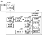
- FIG. 1 is a diagram illustrating a schematic configuration example of a charge/discharge device according to a first embodiment of the present technology.
- FIG. 2 is a diagram showing an example of a waveform of an intermittent current pulse.
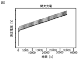
- FIG. 3 is a diagram showing an example of an intermittent charging curve of a secondary battery when the intermittent charging pulses of FIG. 2 are applied to the secondary battery.
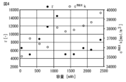
- FIG. 4 is a diagram illustrating an example of model parameters.
- FIG. 5 is a diagram showing an example of the change over time in the voltage value (measured value) of a secondary battery and the voltage value (calculated value) of a battery model.
- FIG. 1 is a diagram illustrating a schematic configuration example of a charge/discharge device according to a first embodiment of the present technology.
- FIG. 2 is a diagram showing an example of a waveform of an intermittent current pulse.
- FIG. 3 is a diagram showing an example of an intermittent charging curve of a secondary battery when the intermittent charging pulses of FIG. 2 are applied to
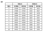
- FIG. 6 is a diagram showing an example of calculated and measured values of dischargeable time when a secondary battery and a battery model are discharged under two different conditions (discharge currents of 500 mA and 2500 mA).
- FIG. 7 is a diagram showing an example of a procedure for diagnosing the secondary battery in the charge/discharge device of FIG.
- FIG. 8 is a diagram illustrating a schematic configuration example of a charge/discharge system according to a second embodiment of the present technology.
- FIG. 9 is a diagram illustrating a schematic configuration example of a charge/discharge system according to a third embodiment of the present technology.
- First embodiment Example of diagnosing a secondary battery in a charge/discharge circuit (FIGS. 1 to 7) 2.
- Second embodiment Example of diagnosing a secondary battery in a server device on a network (FIG. 8) 3.
- Third embodiment Example in which a secondary battery diagnosis function is provided to a secondary battery (FIG. 9)
- the charging/discharging device 200 is a device that charges and discharges a secondary battery pack 100, and is a stand-alone device that does not have a function of communicating with an external device.
- the charging/discharging device 200 has not only the function of charging and discharging the secondary battery pack 100, but also the function of presenting a secondary use destination of the secondary battery pack 100.
- a "secondary use destination" refers to a new use destination of the used secondary battery pack 100.
- the secondary battery pack 100 includes, for example, a secondary battery 110, as shown in FIG. 1.
- the secondary battery 110 is a lithium-ion secondary battery.
- the lithium-ion secondary battery included in the secondary battery 110 may be a unit cell, a battery block in which multiple unit cells are connected, or an assembled battery in which a battery block and accessories are integrally packed. In an assembled battery, multiple lithium-ion secondary batteries are connected in series. The assembled battery may also include multiple lithium-ion secondary batteries electrically connected in parallel.
- a_i specific surface area of active material of electrode i [1/m]
- c_i Li ion concentration at electrode i [mol/m3]
- c_i ⁇ ( max) Maximum Li ion concentration at electrode i [mol/m3]
- D_i Li-ion diffusion coefficient in electrode i [m2/s]
- F Faraday constant [C/mol] i_0, i: exchange current density of electrode i [A/m2]
- I_i Electrode current density [A/m2]
- j_i Li ion flux at the surface of the active material of electrode i [mol/m2s]
- R Gas constant [J/molK]
- R_i Particle size of active material in electrode i [m]
- r_i active material spatial coordinate in electrode i [r]
- T Temperature [K] t: time [s] t_h: Time equivalent to 1 hour [s]
- U_i OCV of electrode i [V]
- V Cell
- the flux of Li ions on the surface of the active material is expressed by formula (4), and the specific surface area is expressed by formula (5) assuming a spherical active material.
- the cell voltage is calculated from the difference between the open circuit voltages (OCVs) corresponding to the surface state of charge (SOCs) of the positive and negative electrodes and the overvoltages of the positive and negative electrodes using equation (6).
- OCVs open circuit voltages
- SOCs surface state of charge
- equations (1) to (8) are optimized for the actual secondary battery 110, and then the equations are solved under appropriate initial and environmental conditions to calculate the cell voltage shown in equation (6).
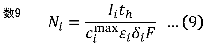
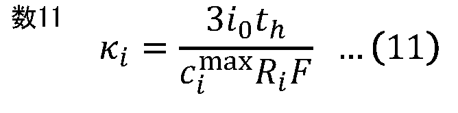
- variables of formula (9), formula (10), and formula (11) are further introduced. These variables correspond to the charge/discharge rate based on the amount of active material available in the electrode, the time constant of Li ion diffusion in the active material, and the rate at which the active material is charged/discharged at the exchange current density, respectively.
- N + , x +, 0 , N- , x-, 0, ⁇ , k+, and k- included in battery model 253 are determined for current and voltage data (current value, voltage value) obtained by intermittent charging.
- a voltage response is calculated when a similar current is input using battery model 253 for current and voltage data ( current value, voltage value) obtained by intermittent charging, and parameters 252 are determined so that these errors are minimized.
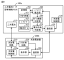
- the charging/discharging device 200 includes, for example, a charging/discharging circuit 210, a charging/discharging control unit 220, an IV measurement circuit 230, a parameter estimation unit 240, a memory unit 250, a model accuracy determination unit 260, a battery performance determination unit 270, and a display unit 280, as shown in FIG. 1.
- the charge/discharge circuit 210 has a charge circuit for charging the secondary battery 110 and a discharge circuit for discharging the secondary battery 110.
- the charge circuit includes, for example, a generator and a converter.
- the charge/discharge control unit 220 controls the current for charging the secondary battery 110 and the current for discharging the secondary battery 110.
- the charge/discharge control unit 220 is, for example, configured with an MPU (Micro-Processing Unit) that performs charge/discharge control, or a CPU (Central Processing Unit) in which a charge/discharge control program is loaded.
- MPU Micro-Processing Unit
- CPU Central Processing Unit
- the charge/discharge control unit 220 controls the charge/discharge circuit 210 to discharge the secondary battery 110 to a predetermined voltage (a first voltage (e.g., 2.5 V)) and then intermittently charge the secondary battery 110 to a predetermined voltage (a second voltage (e.g., 4.2 V) higher than the first voltage).
- a predetermined voltage e.g., 2.5 V
- a second voltage e.g., 4.2 V
- the charge/discharge circuit 210 applies an intermittent current (multiple constant current pulses) to the secondary battery 110 to intermittently charge the secondary battery 110, as shown in FIG. 2, for example.
- FIG. 2 illustrates an example of an intermittent current waveform obtained by measuring the current applied to the secondary battery 110 from the charge/discharge circuit 210 with the IV measurement circuit 230.
- the width of the constant current pulse is, for example, 60 seconds
- the period of the constant current pulse is, for example, 600 seconds.
- Figure 3 shows an example of an intermittent charging waveform obtained by measuring the voltage of the secondary battery 110 with the IV measurement circuit 230 when an intermittent current is applied to the secondary battery 110 from the charge/discharge circuit 210.
- the intermittent charging waveform shown in Figure 3 when a constant current pulse is applied to the secondary battery 110, the charging voltage rises in response, and when the application of the constant current pulse to the secondary battery 110 is stopped, the charging voltage decreases in response, the rate at which the charging voltage decreases gradually becomes more gradual, and the charging voltage becomes a constant value.
- the IV measurement circuit 230 includes a measurement circuit that measures the current and voltage of the secondary battery 110.
- the IV measurement circuit 230 measures the current and voltage of the secondary battery 110 while the secondary battery 110 is being discharged (while the secondary battery 110 is being discharged to a first voltage) and while the secondary battery 110 is being charged (while the secondary battery 110 is being intermittently charged from the first voltage to a second voltage).
- the IV measurement circuit 230 outputs the current value obtained by measurement in the measurement circuit and the voltage value obtained by measurement in the measurement circuit to the parameter estimation unit 240.
- the parameter estimation unit 240 estimates model parameters (parameters 252) of the battery model 253 based on the voltage and current values (IV measurement values 251 described below) of the secondary battery 110 obtained during intermittent charging.
- the above-mentioned method is applied to estimate the parameters 252.
- the methods described in Non-Patent Document 1 (IEEE Transactions on Control Systems Technology, 27, 5, 1862-1877, 2019) and Non-Patent Document 2 (Electrochemical and Solid-State Letters, 14, A39-A41, 2011) can be applied instead of the above-mentioned method.
- the parameter estimation unit 240 estimates the parameter 252 according to a capacity corresponding to a charging voltage while the secondary battery 110 is intermittently charged from a first voltage to a second voltage.
- values of two parameters ( ⁇ , c max k) obtained according to a capacity corresponding to a charging voltage while the secondary battery 110 is intermittently charged from a first voltage to a second voltage are illustrated.
- the storage unit 250 is composed of, for example, a volatile memory such as a Dynamic Random Access Memory (DRAM), or a non-volatile memory such as an Electrically Erasable Programmable Read-Only Memory (EEPROM) or a flash memory.
- the storage unit 250 stores, for example, an IV measurement value 251, parameters 252, and a battery model 253.
- the IV measurement value 251 includes data obtained by the IV measurement circuit 230 measuring the current and voltage of the secondary battery 110 while the secondary battery 110 is being discharged (while the secondary battery 110 is being discharged to the first voltage).
- the IV measurement value 251 further includes data obtained by the IV measurement circuit 230 measuring the current and voltage of the secondary battery 110 while the secondary battery 110 is being charged (while the secondary battery 110 is being intermittently charged from the first voltage to the second voltage).
- Parameter 252 is a parameter of battery model 253 obtained by parameter estimation unit 240.
- Battery model 253 is a model of secondary battery 110, and outputs a voltage value during charging or discharging based on parameter 252, and a charging state corresponding to that voltage value.
- the model accuracy determination unit 260 determines the accuracy of the battery model 253. Specifically, the model accuracy determination unit 260 compares the voltage value (measured value) of the secondary battery 110 obtained during discharge (while the secondary battery 110 is discharged to the first voltage) with the voltage value (calculated value) during discharge obtained from the battery model 253 to which the parameters 252 obtained by estimation are applied, to determine the accuracy of the battery model 253.
- the model accuracy determination unit 260 determines that the battery model 253 has sufficient accuracy when, for example, the difference between the measured value and the calculated value at the same time falls within a predetermined range as shown in FIG. 5. The model accuracy determination unit 260 determines that the battery model 253 does not have sufficient accuracy when, for example, the difference between the measured value and the calculated value at the same time falls outside a predetermined range.
- the model accuracy determination unit 260 calculates the dischargeable time while maintaining a predetermined discharge condition (e.g., discharge current of 500 mA and 2500 mA) based on the measured values and the calculated values, for example, as shown in FIG. 6.
- a predetermined discharge condition e.g., discharge current of 500 mA and 2500 mA
- FIG. 6 illustrates an example of ten secondary batteries 110 with different deterioration conditions and the dischargeable times obtained from their corresponding battery models 253.
- the model accuracy determination unit 260 determines that the battery model 253 has sufficient accuracy.
- the model accuracy determination unit 260 determines that the battery model 253 does not have sufficient accuracy.
- the battery performance determination unit 270 uses the battery model 253 to which the parameters 252 obtained by estimation are applied to determine the performance of the secondary battery 110.
- the battery performance determination unit 270 determines the performance of the secondary battery 110 for, for example, a hypothetical application. Examples of hypothetical applications include applications with few opportunities for rapid discharge, applications with few opportunities for rapid power reception, applications in which the battery is not left in a fully charged or fully discharged state for a short time, and applications in which the battery is not left in a low temperature environment for a short time.
- the battery performance determination unit 270 determines the performance of the secondary battery 110 for each application, for example, based on the required specifications set for each application and the IV measurement value 251.
- the battery performance determination unit 270 derives a secondary use of the secondary battery 110 based on the performance of the secondary battery 110 obtained by the determination. For example, the battery performance determination unit 270 determines that the secondary use of the secondary battery 110 is an application for which the performance of the secondary battery 110 is determined to be sufficient. The battery performance determination unit 270 outputs a video signal including information about the secondary use of the secondary battery 110 to the display unit 280. For example, if there is no application for which the performance of the secondary battery 110 is determined to be sufficient, the battery performance determination unit 270 outputs a video signal including information indicating that to the display unit 280.
- the display unit 280 displays an image based on the video signal obtained from the battery performance determination unit 270. For example, when the display unit 280 receives a video signal including information about secondary uses of the secondary battery 110, the display unit 280 displays the information about the secondary uses of the secondary battery 110. For example, when the display unit 280 receives a video signal including information indicating that there is no use for which the performance of the secondary battery 110 has been determined to be sufficient, the display unit 280 displays that there is no secondary use of the secondary battery 110.
- a lighting device may be provided that indicates the presence or absence of a secondary use or a specific example of a secondary use. In this case, the lighting device lights up to indicate the presence or absence of a secondary use or a specific example of a secondary use.
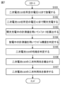
- Figure 7 shows an example of a procedure for diagnosing a secondary battery in the charging/discharging device 200.
- the charging/discharging circuit 210 discharges the secondary battery 110 to a predetermined voltage V1 (first voltage) (step S101).
- the charging/discharging circuit 210 then intermittently charges the secondary battery 110 from the predetermined voltage V1 (first voltage) to a predetermined voltage V2 (second voltage) (step S102).
- the IV measurement circuit 230 measures the current and voltage of the secondary battery 110 in steps S101 and S102, and outputs the thus obtained current and voltage values to the parameter estimation unit 240 as IV measurement values 251.
- the parameter estimation unit 240 temporarily stores the IV measurement values 251 in the memory unit 250.
- the parameter estimation unit 240 calculates model parameters (parameters 252) of the battery model 253 based on the IV measurement values 251 (the voltage and current values of the secondary battery 110 obtained during intermittent charging) (step S103).
- the parameter estimation unit 240 notifies the model accuracy determination unit 260 that the calculation of parameters 252 has been completed.
- the model accuracy determination unit 260 receives the notification from the parameter estimation unit 240, it determines the accuracy of the battery model 253 (step S104). Specifically, the model accuracy determination unit 260 compares the voltage value (measured value) of the secondary battery 110 obtained during discharge (while the secondary battery 110 is discharged to the first voltage) with the voltage value (calculated value) during discharge obtained from the battery model 253 to which the parameters 252 obtained by estimation are applied, to determine the accuracy of the battery model 253.
- the battery performance determination unit 270 determines the performance of the secondary battery 110 using the battery model 253 to which the parameters 252 have been applied (step S105).
- the battery performance determination unit 270 derives the secondary use destination of the secondary battery 110 based on the performance of the secondary battery 110 obtained by the determination (step S106).
- the display unit 280 displays the secondary use destination of the secondary battery 110 (step S107).
- parameters 252 of battery model 253 are estimated based on the voltage and current values of secondary battery 110 obtained during intermittent charging, and the accuracy of battery model 253 is determined by comparing the voltage value of secondary battery 110 obtained during discharging with the voltage value during discharging obtained from battery model 253 to which estimated parameters 252 are applied. This makes it possible to evaluate the SOC dependency of parameters 252, and generate a battery model 253 with good accuracy. Furthermore, since the accuracy of battery model 253 is determined using the voltage value obtained during discharging, the accuracy of battery model 253 can be guaranteed.
- the second voltage is higher than the first voltage. This allows the SOC dependency of the parameter 252 to be evaluated over a wide range, making it possible to generate a highly accurate battery model 253.
- intermittent charging is performed by applying multiple constant current pulses to the secondary battery 110. This allows intermittent charging to be performed using a DC power source, eliminating the need to use an AC power source and allowing the charging/discharging device 200 to be realized with simple equipment.
- the performance of the secondary battery 110 is determined using the battery model 253 to which the parameters 252 obtained by estimation are applied. Furthermore, a secondary use destination of the secondary battery 110 is derived based on the performance of the secondary battery 110 obtained by the determination. This makes it possible to present a secondary use destination of the secondary battery 110 with high accuracy.
- FIG. 8 illustrates a schematic configuration example of the power supply system according to the present embodiment.
- the power supply system includes a secondary battery pack 100, a charging/discharging device 200a, and a server device 300.
- the charging/discharging device 200a and the server device 300 are connected via a communication network 400.
- the charging/discharging device 200a and the server device 300 are capable of communicating with each other via the communication network 400.
- the communication network 400 includes, for example, the Internet, a cloud network, or a network specific to an operator.
- the charging/discharging device 200a is a device that charges and discharges the secondary battery pack 100, and is a network communication type device that has the function of communicating with external devices.
- the charging/discharging device 200a has a configuration in which the parameter estimation unit 240, the storage unit 250, the model accuracy determination unit 260, and the battery performance determination unit 270 are omitted from the charging/discharging device 200 according to the above embodiment.
- the charging/discharging device 200a further includes a communication unit 290.
- the communication unit 290 is a communication interface that communicates with the server device 300 via the communication network 400.
- the server device 300 includes, for example, a parameter estimation unit 240, a storage unit 250, a model accuracy determination unit 260, a battery performance determination unit 270, and a communication unit 310.
- the communication unit 310 is a communication interface that communicates with the charging/discharging device 200a via the communication network 400.
- the IV measurement circuit 230 transmits the IV measurement value 251 to the server device 300 via the communication unit 290.
- the parameter estimation unit 240 receives the IV measurement value 251 from the server device 300 via the communication unit 290. If the battery performance determination unit 270 finds a secondary use destination for the secondary battery 110, it transmits information about the secondary use destination for the secondary battery 110 to the charging/discharging device 200a via the communication unit 310. If the battery performance determination unit 270 does not find a secondary use destination for the secondary battery 110, it transmits information indicating that there is no secondary use destination for the secondary battery 110 to the charging/discharging device 200a via the communication unit 310.
- the server device 300 is provided with a function for deriving the parameters 252 of the battery model 253, as well as the performance and secondary usage of the secondary battery 110. Even in this case, it is possible to obtain a highly accurate battery model, as in the above embodiment.
- a power supply system including a secondary battery pack 100a with a secondary battery diagnostic function according to a third embodiment of the present technology will be described.
- Fig. 9 shows a schematic configuration example of the power supply system according to the present embodiment.
- the power supply system includes a secondary battery pack 100a and a charging/discharging device 200b.
- the secondary battery pack 100a includes a secondary battery 110, a parameter estimation unit 240, a memory unit 250, a model accuracy determination unit 260, a battery performance determination unit 270, a charge/discharge control unit 120, and a communication unit 130.
- the communication unit 130 is an interface capable of exchanging data with the charge/discharge device 200b.
- the charge/discharge control unit 120 controls the charge/discharge control unit 220a of the charge/discharge device 200b via the communication unit 130.
- the charge/discharge control unit 120 is configured, for example, by an MPU that performs charge/discharge control, or a CPU loaded with a charge/discharge control program.
- the charge/discharge control unit 120 outputs a control signal to the charge/discharge control unit 220a via the communication unit 130 to control the charge/discharge circuit 210 so that the secondary battery 110 is discharged to a predetermined voltage (a first voltage (e.g., 2.5 V)) and then intermittently charged to a predetermined voltage (a second voltage (e.g., 4.2 V) higher than the first voltage).
- a predetermined voltage e.g., 2.5 V
- a second voltage e.g., 4.2 V
- the charging/discharging device 200b includes, for example, a charging/discharging circuit 210, a charging/discharging control unit 220a, an IV measurement circuit 230, a display unit 280, and a communication unit 290, as shown in FIG. 9.
- the communication unit 290 is an interface capable of exchanging data with the secondary battery pack 100a.
- the charging/discharging control unit 220a acquires a control signal from the secondary battery pack 100a, it controls the charging/discharging circuit 210 based on the acquired control signal.
- the charging/discharging control unit 220a controls the charging/discharging circuit 210 based on the acquired control signal to discharge the secondary battery 110 to a predetermined voltage (a first voltage (e.g., 2.5 V)) and then intermittently charge the secondary battery 110 to a predetermined voltage (a second voltage (e.g., 4.2 V) higher than the first voltage).
- a predetermined voltage e.g., 2.5 V
- a second voltage e.g., 4.2 V
- the secondary battery pack 100a is provided with a function for deriving the parameters 252 of the battery model 253, as well as the performance and secondary use of the secondary battery 110. Even in this case, it is possible to obtain a highly accurate battery model, as in the above embodiment.
- the present technology can also be configured as follows. ⁇ 1> discharging the secondary battery to a first voltage and then intermittently charging the secondary battery to a second voltage; measuring a voltage and a current of the secondary battery during discharging and intermittent charging of the secondary battery; estimating model parameters of a battery model based on voltage values and current values of the secondary battery obtained during the intermittent charging; and determining accuracy of the battery model by comparing a voltage value of the secondary battery obtained during the discharging with a voltage value during discharging obtained from the battery model to which the model parameters obtained by estimation are applied.
- ⁇ 3> The method for generating secondary battery model parameters according to ⁇ 1> or ⁇ 2>, wherein the intermittent charging is performed by applying a plurality of constant current pulses to the secondary battery.
- ⁇ 6> an estimation unit that estimates model parameters of a battery model based on voltage values and current values obtained during intermittent charging of a secondary battery among voltage values and current values of the secondary battery obtained by measurement while the secondary battery is discharged to a first voltage and then intermittently charged to a second voltage; a determination unit that determines accuracy of the battery model by comparing a voltage value of the secondary battery obtained during the discharging with a voltage value during discharging obtained from the battery model to which the model parameters obtained by estimation are applied.
- ⁇ 7> The secondary battery model parameter generating device according to ⁇ 6>, wherein the second voltage is higher than the first voltage.
- ⁇ 8> The secondary battery model parameter generation device according to ⁇ 6> or ⁇ 7>, wherein the charge/discharge circuit performs the intermittent charging by applying a plurality of constant current pulses to the secondary battery.
- ⁇ 9> The secondary battery model parameter generation device described in any one of ⁇ 6> to ⁇ 8>, wherein, when the determination unit determines that the accuracy of the battery model is sufficient, the determination unit determines the performance of the secondary battery using the battery model to which the model parameters obtained by estimation are applied.
- ⁇ 10> The secondary battery model parameter generation device according to ⁇ 9>, wherein the determination unit derives a secondary usage destination of the secondary battery based on the performance of the secondary battery obtained by the determination.
- ⁇ 11> discharging the secondary battery to a first voltage and then intermittently charging the secondary battery to a second voltage; measuring a voltage and a current of the secondary battery during discharging and intermittent charging of the secondary battery; estimating model parameters of a battery model based on voltage values and current values of the secondary battery obtained during the intermittent charging; comparing a voltage value of the secondary battery obtained during the discharging with a voltage value during discharging obtained from the battery model to which the model parameters obtained by estimation are applied to determine accuracy of the battery model; and when it is determined that the accuracy of the battery model is sufficient, determining performance of the secondary battery using the battery model to which the model parameters obtained by estimation are applied.
- the secondary battery diagnosis method further comprising: determining a secondary use of the secondary battery based on the performance of the secondary battery obtained by the determination.
- an estimation unit that estimates model parameters of a battery model based on voltage values and current values obtained during intermittent charging of a secondary battery among voltage values and current values of the secondary battery obtained by measurement while the secondary battery is discharged to a first voltage and then intermittently charged to a second voltage; a determination unit that determines the accuracy of the battery model by comparing a voltage value of the secondary battery obtained during the discharge with a voltage value during discharge obtained from the battery model to which the model parameters obtained by estimation are applied, and when it is determined that the accuracy of the battery model is sufficient, determines the performance of the secondary battery using the battery model to which the model parameters obtained by estimation are applied.
- ⁇ 14> a charge/discharge circuit that discharges the secondary battery to the first voltage and then intermittently charges the secondary battery to the second voltage;
- the secondary battery diagnostic device according to ⁇ 13>, further comprising: a measurement circuit that measures a voltage and a current of the secondary battery during discharging and intermittent charging of the secondary battery.
- ⁇ 16> a charge/discharge circuit that discharges the secondary battery to a first voltage and then intermittently charges the secondary battery to a second voltage; a measurement circuit that measures a voltage and a current of the secondary battery during discharging and intermittent charging of the secondary battery; an estimation unit that estimates model parameters of a battery model based on a voltage value and a current value of the secondary battery obtained during the intermittent charging; a determination unit that determines the accuracy of the battery model by comparing a voltage value of the secondary battery obtained during the discharging with a voltage value during discharging obtained from the battery model to which the model parameters obtained by estimation are applied, and when it is determined that the accuracy of the battery model is sufficient, determines the performance of the secondary battery using the battery model to which the model parameters obtained by estimation are applied.
- the charging/discharging device according to ⁇ 16>, wherein the determining unit derives a secondary usage destination of the secondary battery based on the performance of the secondary battery obtained by the determination.
- a secondary battery an estimation unit that estimates model parameters of a battery model based on voltage values and current values obtained during intermittent charging, among voltage values and current values of the secondary battery obtained by measurement while the secondary battery is discharged to a first voltage and then intermittently charged to a second voltage; a determination unit that determines accuracy of the battery model by comparing a voltage value of the secondary battery obtained during the discharging with a voltage value during discharging obtained from the battery model to which the model parameters obtained by estimation are applied, and when it is determined that the accuracy of the battery model is sufficient, determines performance of the secondary battery using the battery model to which the model parameters obtained by estimation are applied.
- the determining unit derives a secondary usage destination of the secondary battery based on the performance of the secondary battery obtained by the determination.
Landscapes
- Engineering & Computer Science (AREA)
- Physics & Mathematics (AREA)
- General Physics & Mathematics (AREA)
- Power Engineering (AREA)
- Manufacturing & Machinery (AREA)
- Chemical & Material Sciences (AREA)
- Chemical Kinetics & Catalysis (AREA)
- Electrochemistry (AREA)
- General Chemical & Material Sciences (AREA)
- Secondary Cells (AREA)
- Charge And Discharge Circuits For Batteries Or The Like (AREA)
Abstract
本技術の一側面に係る二次電池モデルパラメータ生成方法は、以下の4つを含む。 (1)二次電池を第1電圧まで放電した後、第2電圧まで間欠充電すること (2)前記二次電池に対する放電および間欠充電の間、前記二次電池の電圧および電流を計測すること (3)前記間欠充電の間に得られた前記二次電池の電圧値および電流値に基づいて電池モデルのモデルパラメータを推定すること (4)前記放電の間に得られた前記二次電池の電圧値と、推定により得られた前記モデルパラメータを適用した前記電池モデルから得られた放電時の電圧値とを比較して、前記電池モデルの精度を判定すること
Description
本技術は、二次電池モデルパラメータ生成方法、二次電池モデルパラメータ生成装置、二次電池診断方法、二次電池診断装置、充放電装置および二次電池パックに関する。
リチウムイオン二次電池の使用用途の拡大に伴い、原料となるリチウムやコバルトなどの天然資源の枯渇が問題となってきている。この問題を解決する一つの方法として、リチウムイオン二次電池をその製品寿命が全うされるまで繰り返し再利用する方法が考えられる。効率よく二次利用する上で、一次利用を終了した時点の二次電池の劣化状態を適切に把握し、かつ、その劣化状態に合わせた二次利用を行うことが重要となる。
二次電池の劣化状態を推定するために電池モデルを用いることが考えられる(例えば、特許文献1参照)。
しかし、特許文献1に記載の方法では、駆動輪を駆動させるモータに電力を供給するバッテリの、車両走行時の電流の計測値を用いて電池モデルのパラメータが算出される。そのため、走行パターンに依存した電池モデルが生成され、精度の良い電池モデルが得られない可能性がある。
従って、精度の良い電池モデルを得ることを可能にする二次電池モデルパラメータ生成方法、および二次電池モデルパラメータ生成装置を提供することが望ましい。さらに、そのような二次電池モデルパラメータ生成方法を用いた二次電池診断方法、および二次電池診断装置を提供することが望ましい。さらに、そのような二次電池診断装置を備えた充放電装置および二次電池パックを提供することが望ましい。
本技術の第1の側面に係る二次電池モデルパラメータ生成方法は、以下の4つを含む。
(A1)二次電池を第1電圧まで放電した後、第2電圧まで間欠充電すること
(A2)前記二次電池に対する放電および間欠充電の間、前記二次電池の電圧および電流を計測すること
(A3)前記間欠充電の間に得られた前記二次電池の電圧値および電流値に基づいて電池モデルのモデルパラメータを推定すること
(A4)前記放電の間に得られた前記二次電池の電圧値と、推定により得られた前記モデルパラメータを適用した前記電池モデルから得られた放電時の電圧値とを比較して、前記電池モデルの精度を判定すること
(A1)二次電池を第1電圧まで放電した後、第2電圧まで間欠充電すること
(A2)前記二次電池に対する放電および間欠充電の間、前記二次電池の電圧および電流を計測すること
(A3)前記間欠充電の間に得られた前記二次電池の電圧値および電流値に基づいて電池モデルのモデルパラメータを推定すること
(A4)前記放電の間に得られた前記二次電池の電圧値と、推定により得られた前記モデルパラメータを適用した前記電池モデルから得られた放電時の電圧値とを比較して、前記電池モデルの精度を判定すること
本技術の第2の側面に係る二次電池モデルパラメータ生成装置は、推定部と、判定部とを備えている。前記推定部は、二次電池が第1電圧まで放電され、その後、第2電圧まで間欠充電される間の計測により得られた、前記二次電池の電圧値および電流値のうち、前記間欠充電の間に得られた電圧値および電流値に基づいて電池モデルのモデルパラメータを推定する。前記判定部は、前記放電の間に得られた前記二次電池の電圧値と、推定により得られた前記モデルパラメータを適用した前記電池モデルから得られた放電時の電圧値とを比較して、前記電池モデルの精度を判定する。
本技術の第3の側面に係る二次電池診断方法は、以下の5つを含む。
(B1)二次電池を第1電圧まで放電した後、第2電圧まで間欠充電すること
(B2)前記二次電池に対する放電および間欠充電の間、前記二次電池の電圧および電流を計測すること
(B3)前記間欠充電の間に得られた前記二次電池の電圧値および電流値に基づいて電池モデルのモデルパラメータを推定すること
(B4)前記放電の間に得られた前記二次電池の電圧値と、推定により得られた前記モデルパラメータを適用した前記電池モデルから得られた放電時の電圧値とを比較して、前記電池モデルの精度を判定すること
(B5)前記電池モデルの精度が十分であると判定された場合に、推定により得られた前記モデルパラメータを適用した前記電池モデルを利用して前記二次電池の性能を判定すること
(B1)二次電池を第1電圧まで放電した後、第2電圧まで間欠充電すること
(B2)前記二次電池に対する放電および間欠充電の間、前記二次電池の電圧および電流を計測すること
(B3)前記間欠充電の間に得られた前記二次電池の電圧値および電流値に基づいて電池モデルのモデルパラメータを推定すること
(B4)前記放電の間に得られた前記二次電池の電圧値と、推定により得られた前記モデルパラメータを適用した前記電池モデルから得られた放電時の電圧値とを比較して、前記電池モデルの精度を判定すること
(B5)前記電池モデルの精度が十分であると判定された場合に、推定により得られた前記モデルパラメータを適用した前記電池モデルを利用して前記二次電池の性能を判定すること
本技術の第4の側面に係る二次電池診断装置は、推定部と、判定部とを備えている。前記推定部は、二次電池が第1電圧まで放電され、その後、第2電圧まで間欠充電される間の計測により得られた、前記二次電池の電圧値および電流値のうち、前記間欠充電の間に得られた電圧値および電流値に基づいて電池モデルのモデルパラメータを推定する。前記判定部は、前記放電の間に得られた前記二次電池の電圧値と、推定により得られた前記モデルパラメータを適用した前記電池モデルから得られた放電時の電圧値とを比較して、前記電池モデルの精度を判定し、前記電池モデルの精度が十分であると判定した場合に、推定により得られた前記モデルパラメータを適用した前記電池モデルを利用して前記二次電池の性能を判定する
本技術の第5の側面に係る充放電装置は、充放電回路と、計測回路と、推定部と、判定部とを備えている。前記充放電回路は、二次電池を第1電圧まで放電した後、第2電圧まで間欠充電する。前記計測回路は、前記二次電池に対する放電および間欠充電の間、前記二次電池の電圧および電流を計測する。前記推定部は、前記間欠充電の間に得られた前記二次電池の電圧値および電流値に基づいて電池モデルのモデルパラメータを推定する。前記判定部は、前記放電の間に得られた前記二次電池の電圧値と、推定により得られた前記モデルパラメータを適用した前記電池モデルから得られた放電時の電圧値とを比較して、前記電池モデルの精度を判定し、前記電池モデルの精度が十分であると判定した場合に、推定により得られた前記モデルパラメータを適用した前記電池モデルを利用して前記二次電池の性能を判定する。
本技術の第6の側面に係る二次電池パックは、二次電池と、推定部と、判定部とを備えている。前記推定部は、前記二次電池が第1電圧まで放電され、その後、第2電圧まで間欠充電される間の計測により得られた、前記二次電池の電圧値および電流値のうち、前記間欠充電の間に得られた電圧値および電流値に基づいて電池モデルのモデルパラメータを推定する。前記判定部は、前記放電の間に得られた前記二次電池の電圧値と、推定により得られた前記モデルパラメータを適用した前記電池モデルから得られた放電時の電圧値とを比較して、前記電池モデルの精度を判定し、前記電池モデルの精度が十分であると判定した場合に、推定により得られた前記モデルパラメータを適用した前記電池モデルを利用して前記二次電池の性能を判定する。
本技術の第1の側面に係る二次電池モデルパラメータ生成方法、本技術の第2の側面に係る二次電池モデルパラメータ生成装置、本技術の第3の側面に係る二次電池診断方法、本技術の第4の側面に係る二次電池診断装置、本技術の第5の側面に係る充放電装置、および本技術の第6の側面に係る二次電池パックでは、間欠充電の間に得られた前記二次電池の電圧値および電流値に基づいて電池モデルのモデルパラメータが推定され、放電の間に得られた前記二次電池の電圧値と、推定により得られた前記モデルパラメータを適用した前記電池モデルから得られた放電時の電圧値とを比較して、前記電池モデルの精度が判定される。これにより、モデルパラメータのSOC依存性を評価することができるので、精度の良い電池モデルを生成することができる。さらに、放電の間に得られた電圧値を用いて電池モデルの精度を判定するので、電池モデルの精度を担保することができる。
なお、本技術の効果は、必ずしもここで説明された効果に限定されるわけではなく、後述する本技術に関連する一連の効果のうちのいずれの効果でもよい。
以下、本技術を実施するための形態について、図面を参照して詳細に説明する。なお、説明する順序は、下記の通りである。
1.第1の実施形態
充放電回路において二次電池を診断する例(図1~図7)
2.第2の実施形態
ネットワーク上のサーバ装置において二次電池を診断する例(図8)
3.第3の実施形態
二次電池に二次電池診断機能が付与されている例(図9)
1.第1の実施形態
充放電回路において二次電池を診断する例(図1~図7)
2.第2の実施形態
ネットワーク上のサーバ装置において二次電池を診断する例(図8)
3.第3の実施形態
二次電池に二次電池診断機能が付与されている例(図9)
<1.第1の実施形態>
[構成]
本技術の第1の実施形態に係る充放電装置200の構成について説明する。充放電装置200は、二次電池パック100を充放電する装置であり、外部の装置と通信する機能を有しないスタンドアロン型の装置である。
[構成]
本技術の第1の実施形態に係る充放電装置200の構成について説明する。充放電装置200は、二次電池パック100を充放電する装置であり、外部の装置と通信する機能を有しないスタンドアロン型の装置である。
充放電装置200は、二次電池パック100を充放電する機能だけでなく、二次電池パック100の二次利用先を提示する機能も備えている。「二次利用先」とは、使用済みの二次電池パック100の新たな利用先を指している。二次電池パック100は、例えば、図1に示したように、二次電池110を備えている。
二次電池110は、リチウムイオン二次電池である。二次電池110に含まれるリチウムイオン二次電池は、単位セルであってもよく、単位セルが複数個接続された電池ブロック、もしくは、電池ブロックおよび付属品が一体的にパッキングされた組電池であってもよい。組電池では、複数のリチウムイオン二次電池が直列に接続されている。組電池内において、電気的に並列に接続された複数のリチウムイオン二次電池が含まれていてもよい。
次に、二次利用先の判定に用いる二次電池モデル(後述の電池モデル253)について説明する。なお、以下に示す式に含まれる各変数は以下の通りである。
a_i:電極iの活物質比表面積 [1/m]
c_i:電極iにおけるLiイオン濃度 [mol/m3]
c_i^( max):電極iにおけるLiイオン濃度の最大値 [mol/m3]
D_i:電極iにおけるLiイオン拡散係数 [m2/s]
F:ファラデー定数 [C/mol]
i_0、i:電極iの交換電流密度 [A/m2]
I_i:電極電流密度 [A/m2]
j_i:電極i活物質表面でのLiイオンフラックス [mol/m2s]
R:気体定数 [J/molK]
R_i:電極iの活物質粒径 [m]
r_i:電極iにおける活物質空間座標 [r]
T:温度 [K]
t:時刻 [s]
t_h:1時間相当の時間 [s]
U_i:電極iのOCV [V]
V:セル電圧 [V]
x_i:電極iのSOC [-]
δ_i:電極iの厚み [m]
ε_i:電極iの活物質体積分率 [-]
η_i:電極iの過電圧 [V]
c_i:電極iにおけるLiイオン濃度 [mol/m3]
c_i^( max):電極iにおけるLiイオン濃度の最大値 [mol/m3]
D_i:電極iにおけるLiイオン拡散係数 [m2/s]
F:ファラデー定数 [C/mol]
i_0、i:電極iの交換電流密度 [A/m2]
I_i:電極電流密度 [A/m2]
j_i:電極i活物質表面でのLiイオンフラックス [mol/m2s]
R:気体定数 [J/molK]
R_i:電極iの活物質粒径 [m]
r_i:電極iにおける活物質空間座標 [r]
T:温度 [K]
t:時刻 [s]
t_h:1時間相当の時間 [s]
U_i:電極iのOCV [V]
V:セル電圧 [V]
x_i:電極iのSOC [-]
δ_i:電極iの厚み [m]
ε_i:電極iの活物質体積分率 [-]
η_i:電極iの過電圧 [V]
電池モデル253では、電極i(正極もしくは負極)におけるLiイオンの拡散が式(1)に示す球状条件におけるフィック型の拡散方程式で解かれる。

r_i=0を活物質粒子の中心、r_i=R_iを活物質粒子の表面とすると、境界条件は、式(2)、式(3)となる。

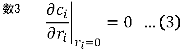
また、活物質表面におけるLiイオンのフラックスは式(4)であり、比表面積は、球状の活物質を仮定した式(5)で表される。
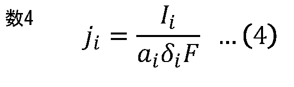

セル電圧は、正負極の表面SOC(State Of Charge;充電率)に対応するOCV(Open Circuit Voltage;開回路電圧)の差分と、正負極の過電圧とから式(6)で計算される。ここで、各電極のSOCは、式(7)で表される。


正負極の過電圧は、式(8)に示したButler-Volmer式に基づいて計算される。

電池モデル253では、式(1)~式(8)に含まれる各パラメータ(後述のパラメータ252)が実際の二次電池110に最適化された後、適切な初期条件および環境条件の下で解くことで、式(6)に示したセル電圧の計算が行われる。
パラメータ252の最適化にあたっては、さらに、式(9)、式(10)、式(11)の変数が導入される。これらの変数は、それぞれ、電極内の有効な活物質量を基準とした充電・放電のレート、活物質中のLiイオン拡散の時定数、活物質を交換電流密度で充電・放電した時のレートに対応する。

さらに、パラメータ252の最適化の過程では、最適化計算の安定性を向上させるために、式(10)、式(11)で示した無次元数に対して次の制約(式(12)、式(13))が課される。


このような条件下で、間欠充電で得られる電流・電圧のデータ(電流値、電圧値)に対して、電池モデル253に含まれるN+およびx+、0,N-,x-、0,τ,k+,k-が決定される。パラメータ252の最適化の最適化においては、間欠充電で得られる電流・電圧のデータ(電流値、電圧値)に対して、電池モデル253を用いて同様の電流を入力した際の電圧応答が計算され、これらの誤差が最小となるようにパラメータ252が決定される。
(充放電装置200の構成)
次に、充放電装置200の構成について説明する。
次に、充放電装置200の構成について説明する。
充放電装置200は、例えば、図1に示したように、充放電回路210、充放電制御部220、IV計測回路230、パラメータ推定部240、記憶部250、モデル精度判定部260、電池性能判定部270および表示部280を備えている。
充放電回路210は、二次電池110を充電する充電回路や、二次電池110を放電させる放電回路を有している。充電回路は、例えば発電機およびコンバータ等を含む。充放電制御部220は、二次電池110を充電するための電流を制御したり、二次電池110を放電させるための電流を制御したりする。充放電制御部220は、例えば、充放電制御を行うMPU(Micro-Processing Unit)、または、充放電制御プログラムがロードされたCPU(Central Processing Unit)によって構成されている。充放電制御部220は、二次電池110を所定の電圧(第1電圧(例えば2.5V))まで放電した後、所定の電圧(第1電圧よりも高い第2電圧(例えば4.2V))まで間欠充電するように充放電回路210を制御する。
充放電回路210は、例えば、図2に示したような、二次電池110を間欠充電させるための間欠電流(複数の定電流パルス)を二次電池110に印可する。図2には、充放電回路210から二次電池110に印可される電流をIV計測回路230で測定することにより得られた間欠電流波形の一例が例示されている。図2に示した間欠電流波形において、定電流パルスの幅は例えば60秒となっており、定電流パルスの周期は例えば600秒となっている。
図3には、充放電回路210から二次電池110に間欠電流が印可されているときの、二次電池110の電圧をIV計測回路230で測定することにより得られた間欠充電波形の一例が例示されている。図3に示した間欠充電波形では、二次電池110に定電流パルスが印可されると、それに応答する形で充電電圧が上昇し、二次電池110への定電流パルスの印可が停止されると、それに応答する形で充電電圧が減少し、充電電圧の減少度合が徐々に緩やかになり、充電電圧が一定値となる。
IV計測回路230は、二次電池110の電流および電圧を計測する計測回路を含む。IV計測回路230は、二次電池110に対する放電の間(二次電池110が第1電圧まで放電される間)と、二次電池110に対する充電の間(二次電池110が第1電圧から第2電圧まで間欠充電される間)とにおいて、二次電池110の電流および電圧を計測する。IV計測回路230は、計測回路での測定により得られた電流値と、計測回路での測定により得られた電圧値とをパラメータ推定部240に出力する。
パラメータ推定部240は、間欠充電の間に得られた二次電池110の電圧値および電流値(後述のIV計測値251)に基づいて電池モデル253のモデルパラメータ(パラメータ252)を推定する。パラメータ252の推定には、上述の方法が適用される。パラメータ252の推定部分については、例えば、上述の方法の代わりに、非特許文献1(IEEE Transactions on Control Systems Technology, 27, 5, 1862-1877, 2019)および非特許文献2(Electrochemical and Solid-State Letters, 14, A39-A41, 2011)に記載の方法が適用可能である。
パラメータ推定部240は、二次電池110が第1電圧から第2電圧まで間欠充電される間の充電電圧に対応する容量に応じてパラメータ252を推定する。図4には、二次電池110が第1電圧から第2電圧まで間欠充電される間の充電電圧に対応する容量に応じて得られた2つのパラメータ(τ、cmaxk)の値が例示されている。
記憶部250は、例えば、DRAM(Dynamic Random Access Memory)などの揮発性メモリ、または、EEPROM(Electrically Erasable Programmable Read-Only Memory)やフラッシュメモリなどの不揮発性メモリで構成されている。記憶部250には、例えば、IV計測値251、パラメータ252および電池モデル253が格納される。
IV計測値251は、二次電池110に対する放電の間(二次電池110が第1電圧まで放電される間)に、IV計測回路230によって二次電池110の電流および電圧を計測することにより得られたデータを含む。IV計測値251は、さらに、二次電池110に対する充電の間(二次電池110が第1電圧から第2電圧まで間欠充電される間)に、IV計測回路230によって二次電池110の電流および電圧を計測することにより得られたデータを含む。
パラメータ252は、パラメータ推定部240によって得られた電池モデル253のパラメータである。電池モデル253は、二次電池110をモデル化したものであり、パラメータ252に基づいた充電時や放電時の電圧値、およびその電圧値に対応する充電状態を出力する。
モデル精度判定部260は、電池モデル253の精度を判定する。具体的には、モデル精度判定部260は、放電の間(二次電池110が第1電圧まで放電される間)に得られた二次電池110の電圧値(測定値)と、推定により得られたパラメータ252を適用した電池モデル253から得られた放電時の電圧値(計算値)とを比較して、電池モデル253の精度を判定する。
モデル精度判定部260は、例えば、図5に示したように同一時刻での測定値と計算値との差分が所定の範囲内に収まっているときは、電池モデル253が十分な精度を有していると判定する。モデル精度判定部260は、例えば、同一時刻での測定値と計算値との差分が所定の範囲から外れているときは、電池モデル253が十分な精度を有していないと判定する。
モデル精度判定部260は、例えば、図6に示したように、測定値および計算値に基づいて、所定の放電条件(例えば、放電電流500mAおよび2500mA)を維持した状態での放電可能時間を計算する。図6には、劣化条件の異なる10個の二次電池110およびそれらに対応する電池モデル253から得られた放電可能時間が例示されている。モデル精度判定部260は、例えば、測定値から得られた放電可能時間と、計算値から得られた放電可能時間との差分が所定の範囲内に収まっているときは、電池モデル253が十分な精度を有していると判定する。モデル精度判定部260は、例えば、測定値から得られた放電可能時間と、計算値から得られた放電可能時間との差分が所定の範囲から外れているときは、電池モデル253が十分な精度を有していないと判定する。
電池性能判定部270は、電池モデル253の精度が十分であると判定された場合に、推定により得られたパラメータ252を適用した電池モデル253を利用して二次電池110の性能を判定する。電池性能判定部270は、例えば、仮想的な用途での二次電池110の性能を判定する。仮想的な用途としては、例えば、急速放電の機会が少ない用途、急速受電の機会が少ない用途、満充電状態もしくは完全放電状態に置かれる時間が少ない用途、低温環境に置かれる時間が少ない用途などが挙げられる。電池性能判定部270は、例えば、用途ごとに設定された要求仕様と、IV計測値251とに基づいて、用途ごとに二次電池110の性能を判定する。
電池性能判定部270は、判定により得られた二次電池110の性能に基づいて二次電池110の二次利用先を導出する。電池性能判定部270は、例えば、二次電池110の性能が十分であると判定した用途を、二次電池110の二次利用先とする。電池性能判定部270は、二次電池110の二次利用先についての情報を含む映像信号を表示部280に出力する。電池性能判定部270は、例えば、二次電池110の性能が十分であると判定した用途が存在しなかった場合には、その旨を示す情報を含む映像信号を表示部280に出力する。
表示部280は、電池性能判定部270から得られた映像信号に基づく映像を表示する。表示部280は、例えば、二次電池110の二次利用先についての情報を含む映像信号を取得した場合には、二次電池110の二次利用先についての情報を表示する。表示部280は、例えば、二次電池110の性能が十分であると判定した用途が存在しないことを示す情報を含む映像信号を取得した場合には、二次電池110の二次利用先が存在しないことを表示する。なお、表示部280の代わりに、二次利用先の有無または、二次利用先の具体例を示す点灯装置が設けられていてもよい。この場合、点灯装置が、二次利用先の有無または、二次利用先の具体例を示す点灯を行う。
次に、充放電装置200における二次電池の診断について説明する。
図7は、充放電装置200における二次電池の診断手順の一例を表したものである。まず、充放電回路210は、二次電池110を所定の電圧V1(第1電圧)まで放電する(ステップS101)。充放電回路210は、次に、所定の電圧V1(第1電圧)から所定の電圧V2(第2電圧)まで間欠充電する(ステップS102)。IV計測回路230は、ステップS101,S102のとき、二次電池110の電流および電圧を計測し、それにより得られた電流値および電圧値をIV計測値251としてパラメータ推定部240に出力する。パラメータ推定部240は、IV計測値251を一旦、記憶部250に格納する。
パラメータ推定部240は、IV計測値251(間欠充電の間に得られた二次電池110の電圧値および電流値)に基づいて、電池モデル253のモデルパラメータ(パラメータ252)を算出する(ステップS103)。パラメータ推定部240は、パラメータ252の算出が完了したことをモデル精度判定部260に通知する。
モデル精度判定部260は、パラメータ推定部240からの通知を取得すると、電池モデル253の精度を判定する(ステップS104)。具体的には、モデル精度判定部260は、放電の間(二次電池110が第1電圧まで放電される間)に得られた二次電池110の電圧値(測定値)と、推定により得られたパラメータ252を適用した電池モデル253から得られた放電時の電圧値(計算値)とを比較して、電池モデル253の精度を判定する。
電池性能判定部270は、電池モデル253の精度が十分であると判定された場合に、パラメータ252を適用した電池モデル253を利用して二次電池110の性能を判定する(ステップS105)。電池性能判定部270は、判定により得られた二次電池110の性能に基づいて二次電池110の二次利用先を導出する(ステップS106)。表示部280は、二次電池110の二次利用先を表示する(ステップS107)。
[効果]
次に、充放電装置200の効果について説明する。
次に、充放電装置200の効果について説明する。
本実施の形態では、間欠充電の間に得られた二次電池110の電圧値および電流値に基づいて電池モデル253のパラメータ252が推定され、放電の間に得られた二次電池110の電圧値と、推定により得られたパラメータ252を適用した電池モデル253から得られた放電時の電圧値とを比較して、電池モデル253の精度が判定される。これにより、パラメータ252のSOC依存性を評価することができるので、精度の良い電池モデル253を生成することができる。さらに、放電の間に得られた電圧値を用いて電池モデル253の精度を判定するので、電池モデル253の精度を担保することができる。
本実施の形態では、第2電圧が第1電圧よりも高くなっている。これにより、広範囲でパラメータ252のSOC依存性を評価することができるので、精度の良い電池モデル253を生成することができる。
本実施の形態では、複数の定電流パルスを二次電池110に印可することにより間欠充電が行われる。これにより、直流電源を用いて間欠充電を行うことができるので、交流電源を用いる必要がなく、簡易な設備で充放電装置200を実現することができる。
本実施の形態では、電池モデル253の精度が十分であると判定した場合に、推定により得られたパラメータ252を適用した電池モデル253を利用して二次電池110の性能が判定される。さらに、判定により得られた二次電池110の性能に基づいて二次電池110の二次利用先が導出される。これにより、精度よく二次電池110の二次利用先を提示することができる。
<2.第2の実施形態>
本技術の第2の実施形態に係る二次電池診断装置としてのサーバ装置300を備えた電源システムについて説明する。図8は、本実施の形態に係る電源システムの概略構成例を表したものである。
本技術の第2の実施形態に係る二次電池診断装置としてのサーバ装置300を備えた電源システムについて説明する。図8は、本実施の形態に係る電源システムの概略構成例を表したものである。
電源システムは、二次電池パック100、充放電装置200aおよびサーバ装置300を備えている。充放電装置200aおよびサーバ装置300は、通信ネットワーク400を介して接続されている。充放電装置200aおよびサーバ装置300は、通信ネットワーク400を介して互いに通信可能となっている。通信ネットワーク400は、例えば、インターネット、クラウドネットワーク、または、事業者固有のネットワークなどを含んで構成されている。
充放電装置200aは、二次電池パック100を充放電する装置であり、外部の装置と通信する機能を有するネットワーク通信型の装置である。充放電装置200aは、上記実施の形態に係る充放電装置200において、パラメータ推定部240、記憶部250、モデル精度判定部260および電池性能判定部270が省略された構成となっている。充放電装置200aは、通信部290を更に備えている。通信部290は、通信ネットワーク400を介してサーバ装置300と通信を行う通信インターフェースである。
サーバ装置300は、例えば、図8に示したように、パラメータ推定部240、記憶部250、モデル精度判定部260、電池性能判定部270および通信部310を備えている。通信部310は、通信ネットワーク400を介して充放電装置200aと通信を行う通信インターフェースである。
IV計測回路230は、IV計測値251を、通信部290を介してサーバ装置300に送信する。パラメータ推定部240は、IV計測値251を、通信部290を介してサーバ装置300から受信する。電池性能判定部270は、二次電池110の二次利用先が見つかった場合、二次電池110の二次利用先についての情報を、通信部310を介して充放電装置200aに送信する。電池性能判定部270は、二次電池110の二次利用先が見つからなかった場合、二次電池110の二次利用先が存在しないことを示す情報、通信部310を介して充放電装置200aに送信する。
本実施の形態では、電池モデル253のパラメータ252、ならびに二次電池110の性能および二次利用先を導出する機能がサーバ装置300に設けられている。このようにした場合であっても、上記実施の形態と同様、精度の良い電池モデルを得ることができる。
<3.第3の実施形態>
本技術の第3の実施形態に係る、二次電池診断機能付きの二次電池パック100aを備えた電源システムについて説明する。図9は、本実施の形態に係る電源システムの概略構成例を表したものである。電源システムは、二次電池パック100aおよび充放電装置200bを備えている。
本技術の第3の実施形態に係る、二次電池診断機能付きの二次電池パック100aを備えた電源システムについて説明する。図9は、本実施の形態に係る電源システムの概略構成例を表したものである。電源システムは、二次電池パック100aおよび充放電装置200bを備えている。
二次電池パック100aは、例えば、図9に示したように、二次電池110、パラメータ推定部240、記憶部250、モデル精度判定部260、電池性能判定部270、充放電制御部120および通信部130を備えている。通信部130は、充放電装置200bとデータのやりとりを行うことの可能なインターフェースである。充放電制御部120は、通信部130を介して、充放電装置200bの充放電制御部220aを制御する。
充放電制御部120は、例えば、充放電制御を行うMPU、または、充放電制御プログラムがロードされたCPUによって構成されている。充放電制御部120は、二次電池110を所定の電圧(第1電圧(例えば2.5V))まで放電した後、所定の電圧(第1電圧よりも高い第2電圧(例えば4.2V))まで間欠充電するように充放電回路210を制御する制御信号を、通信部130を介して充放電制御部220aに出力する。
充放電装置200bは、例えば、図9に示したように、充放電回路210、充放電制御部220a、IV計測回路230、表示部280および通信部290を備えている。通信部290は、二次電池パック100aとデータのやりとりを行うことの可能なインターフェースである。充放電制御部220aは、二次電池パック100aから制御信号を取得すると、取得した制御信号に基づいて充放電回路210を制御する。具体的には、充放電制御部220aは、取得した制御信号に基づいて、二次電池110を所定の電圧(第1電圧(例えば2.5V))まで放電した後、所定の電圧(第1電圧よりも高い第2電圧(例えば4.2V))まで間欠充電するように充放電回路210を制御する。
本実施の形態では、電池モデル253のパラメータ252、ならびに二次電池110の性能および二次利用先を導出する機能が二次電池パック100aに設けられている。このようにした場合であっても、上記実施の形態と同様、精度の良い電池モデルを得ることができる。
なお、本技術は、以下のような構成を取ることもできる。
<1>
二次電池を第1電圧まで放電した後、第2電圧まで間欠充電することと、
前記二次電池に対する放電および間欠充電の間、前記二次電池の電圧および電流を計測することと、
前記間欠充電の間に得られた前記二次電池の電圧値および電流値に基づいて電池モデルのモデルパラメータを推定することと、
前記放電の間に得られた前記二次電池の電圧値と、推定により得られた前記モデルパラメータを適用した前記電池モデルから得られた放電時の電圧値とを比較して、前記電池モデルの精度を判定することと
を含む
二次電池モデルパラメータ生成方法。
<2>
前記第2電圧は前記第1電圧よりも高い
<1>に記載の二次電池モデルパラメータ生成方法。
<3>
複数の定電流パルスを前記二次電池に印可することにより前記間欠充電を行う
<1>または<2>に記載の二次電池モデルパラメータ生成方法。
<4>
前記電池モデルの精度が十分であると判定された場合に、推定により得られた前記モデルパラメータを適用した前記電池モデルを利用して前記二次電池の性能を判定することをさらに含む
<1>ないし<3>のいずれか1つに記載の二次電池モデルパラメータ生成方法。
<5>
判定により得られた前記二次電池の性能に基づいて前記二次電池の二次利用先を導出することをさらに含む
<4>に記載の二次電池モデルパラメータ生成方法。
<6>
二次電池が第1電圧まで放電され、その後、第2電圧まで間欠充電される間の計測により得られた、前記二次電池の電圧値および電流値のうち、前記間欠充電の間に得られた電圧値および電流値に基づいて電池モデルのモデルパラメータを推定する推定部と、
前記放電の間に得られた前記二次電池の電圧値と、推定により得られた前記モデルパラメータを適用した前記電池モデルから得られた放電時の電圧値とを比較して、前記電池モデルの精度を判定する判定部と
を備えた
二次電池モデルパラメータ生成装置。
<7>
前記第2電圧は前記第1電圧よりも高い
<6>に記載の二次電池モデルパラメータ生成装置。
<8>
前記充放電回路は、複数の定電流パルスを前記二次電池に印可することにより前記間欠充電を行う
<6>または<7>に記載の二次電池モデルパラメータ生成装置。
<9>
前記判定部は、前記電池モデルの精度が十分であると判定した場合に、推定により得られた前記モデルパラメータを適用した前記電池モデルを利用して前記二次電池の性能を判定する
<6>ないし<8>のいずれか1つに記載の二次電池モデルパラメータ生成装置。
<10>
前記判定部は、判定により得られた前記二次電池の性能に基づいて前記二次電池の二次利用先を導出する
<9>に記載の二次電池モデルパラメータ生成装置。
<11>
二次電池を第1電圧まで放電した後、第2電圧まで間欠充電することと、
前記二次電池に対する放電および間欠充電の間、前記二次電池の電圧および電流を計測することと、
前記間欠充電の間に得られた前記二次電池の電圧値および電流値に基づいて電池モデルのモデルパラメータを推定することと、
前記放電の間に得られた前記二次電池の電圧値と、推定により得られた前記モデルパラメータを適用した前記電池モデルから得られた放電時の電圧値とを比較して、前記電池モデルの精度を判定することと、
前記電池モデルの精度が十分であると判定された場合に、推定により得られた前記モデルパラメータを適用した前記電池モデルを利用して前記二次電池の性能を判定することと
を含む
二次電池診断方法。
<12>
判定により得られた前記二次電池の性能に基づいて前記二次電池の二次利用先を導出することをさらに含む
<11>に記載の二次電池診断方法。
<13>
二次電池が第1電圧まで放電され、その後、第2電圧まで間欠充電される間の計測により得られた、前記二次電池の電圧値および電流値のうち、前記間欠充電の間に得られた電圧値および電流値に基づいて電池モデルのモデルパラメータを推定する推定部と、
前記放電の間に得られた前記二次電池の電圧値と、推定により得られた前記モデルパラメータを適用した前記電池モデルから得られた放電時の電圧値とを比較して、前記電池モデルの精度を判定し、前記電池モデルの精度が十分であると判定した場合に、推定により得られた前記モデルパラメータを適用した前記電池モデルを利用して前記二次電池の性能を判定する判定部と
を備えた
二次電池診断装置。
<14>
前記二次電池を前記第1電圧まで放電した後、前記第2電圧まで間欠充電する充放電回路と、
前記二次電池に対する放電および間欠充電の間、前記二次電池の電圧および電流を計測する計測回路と
をさらに備えた
<13>に記載の二次電池診断装置。
<15>
前記判定部は、判定により得られた前記二次電池の性能に基づいて前記二次電池の二次利用先を導出する
<13>または<14>に記載の二次電池診断装置。
<16>
二次電池を第1電圧まで放電した後、第2電圧まで間欠充電する充放電回路と、
前記二次電池に対する放電および間欠充電の間、前記二次電池の電圧および電流を計測する計測回路と、
前記間欠充電の間に得られた前記二次電池の電圧値および電流値に基づいて電池モデルのモデルパラメータを推定する推定部と、
前記放電の間に得られた前記二次電池の電圧値と、推定により得られた前記モデルパラメータを適用した前記電池モデルから得られた放電時の電圧値とを比較して、前記電池モデルの精度を判定し、前記電池モデルの精度が十分であると判定した場合に、推定により得られた前記モデルパラメータを適用した前記電池モデルを利用して前記二次電池の性能を判定する判定部と
を備えた
充放電装置。
<17>
前記判定部は、判定により得られた前記二次電池の性能に基づいて前記二次電池の二次利用先を導出する
<16>に記載の充放電装置。
<18>
二次電池と、
前記二次電池が第1電圧まで放電され、その後、第2電圧まで間欠充電される間の計測により得られた、前記二次電池の電圧値および電流値のうち、前記間欠充電の間に得られた電圧値および電流値に基づいて電池モデルのモデルパラメータを推定する推定部と、
前記放電の間に得られた前記二次電池の電圧値と、推定により得られた前記モデルパラメータを適用した前記電池モデルから得られた放電時の電圧値とを比較して、前記電池モデルの精度を判定し、前記電池モデルの精度が十分であると判定した場合に、推定により得られた前記モデルパラメータを適用した前記電池モデルを利用して前記二次電池の性能を判定する判定部と
を備えた
二次電池パック。
<19>
前記判定部は、判定により得られた前記二次電池の性能に基づいて前記二次電池の二次利用先を導出する
<18>に記載の二次電池パック。
<1>
二次電池を第1電圧まで放電した後、第2電圧まで間欠充電することと、
前記二次電池に対する放電および間欠充電の間、前記二次電池の電圧および電流を計測することと、
前記間欠充電の間に得られた前記二次電池の電圧値および電流値に基づいて電池モデルのモデルパラメータを推定することと、
前記放電の間に得られた前記二次電池の電圧値と、推定により得られた前記モデルパラメータを適用した前記電池モデルから得られた放電時の電圧値とを比較して、前記電池モデルの精度を判定することと
を含む
二次電池モデルパラメータ生成方法。
<2>
前記第2電圧は前記第1電圧よりも高い
<1>に記載の二次電池モデルパラメータ生成方法。
<3>
複数の定電流パルスを前記二次電池に印可することにより前記間欠充電を行う
<1>または<2>に記載の二次電池モデルパラメータ生成方法。
<4>
前記電池モデルの精度が十分であると判定された場合に、推定により得られた前記モデルパラメータを適用した前記電池モデルを利用して前記二次電池の性能を判定することをさらに含む
<1>ないし<3>のいずれか1つに記載の二次電池モデルパラメータ生成方法。
<5>
判定により得られた前記二次電池の性能に基づいて前記二次電池の二次利用先を導出することをさらに含む
<4>に記載の二次電池モデルパラメータ生成方法。
<6>
二次電池が第1電圧まで放電され、その後、第2電圧まで間欠充電される間の計測により得られた、前記二次電池の電圧値および電流値のうち、前記間欠充電の間に得られた電圧値および電流値に基づいて電池モデルのモデルパラメータを推定する推定部と、
前記放電の間に得られた前記二次電池の電圧値と、推定により得られた前記モデルパラメータを適用した前記電池モデルから得られた放電時の電圧値とを比較して、前記電池モデルの精度を判定する判定部と
を備えた
二次電池モデルパラメータ生成装置。
<7>
前記第2電圧は前記第1電圧よりも高い
<6>に記載の二次電池モデルパラメータ生成装置。
<8>
前記充放電回路は、複数の定電流パルスを前記二次電池に印可することにより前記間欠充電を行う
<6>または<7>に記載の二次電池モデルパラメータ生成装置。
<9>
前記判定部は、前記電池モデルの精度が十分であると判定した場合に、推定により得られた前記モデルパラメータを適用した前記電池モデルを利用して前記二次電池の性能を判定する
<6>ないし<8>のいずれか1つに記載の二次電池モデルパラメータ生成装置。
<10>
前記判定部は、判定により得られた前記二次電池の性能に基づいて前記二次電池の二次利用先を導出する
<9>に記載の二次電池モデルパラメータ生成装置。
<11>
二次電池を第1電圧まで放電した後、第2電圧まで間欠充電することと、
前記二次電池に対する放電および間欠充電の間、前記二次電池の電圧および電流を計測することと、
前記間欠充電の間に得られた前記二次電池の電圧値および電流値に基づいて電池モデルのモデルパラメータを推定することと、
前記放電の間に得られた前記二次電池の電圧値と、推定により得られた前記モデルパラメータを適用した前記電池モデルから得られた放電時の電圧値とを比較して、前記電池モデルの精度を判定することと、
前記電池モデルの精度が十分であると判定された場合に、推定により得られた前記モデルパラメータを適用した前記電池モデルを利用して前記二次電池の性能を判定することと
を含む
二次電池診断方法。
<12>
判定により得られた前記二次電池の性能に基づいて前記二次電池の二次利用先を導出することをさらに含む
<11>に記載の二次電池診断方法。
<13>
二次電池が第1電圧まで放電され、その後、第2電圧まで間欠充電される間の計測により得られた、前記二次電池の電圧値および電流値のうち、前記間欠充電の間に得られた電圧値および電流値に基づいて電池モデルのモデルパラメータを推定する推定部と、
前記放電の間に得られた前記二次電池の電圧値と、推定により得られた前記モデルパラメータを適用した前記電池モデルから得られた放電時の電圧値とを比較して、前記電池モデルの精度を判定し、前記電池モデルの精度が十分であると判定した場合に、推定により得られた前記モデルパラメータを適用した前記電池モデルを利用して前記二次電池の性能を判定する判定部と
を備えた
二次電池診断装置。
<14>
前記二次電池を前記第1電圧まで放電した後、前記第2電圧まで間欠充電する充放電回路と、
前記二次電池に対する放電および間欠充電の間、前記二次電池の電圧および電流を計測する計測回路と
をさらに備えた
<13>に記載の二次電池診断装置。
<15>
前記判定部は、判定により得られた前記二次電池の性能に基づいて前記二次電池の二次利用先を導出する
<13>または<14>に記載の二次電池診断装置。
<16>
二次電池を第1電圧まで放電した後、第2電圧まで間欠充電する充放電回路と、
前記二次電池に対する放電および間欠充電の間、前記二次電池の電圧および電流を計測する計測回路と、
前記間欠充電の間に得られた前記二次電池の電圧値および電流値に基づいて電池モデルのモデルパラメータを推定する推定部と、
前記放電の間に得られた前記二次電池の電圧値と、推定により得られた前記モデルパラメータを適用した前記電池モデルから得られた放電時の電圧値とを比較して、前記電池モデルの精度を判定し、前記電池モデルの精度が十分であると判定した場合に、推定により得られた前記モデルパラメータを適用した前記電池モデルを利用して前記二次電池の性能を判定する判定部と
を備えた
充放電装置。
<17>
前記判定部は、判定により得られた前記二次電池の性能に基づいて前記二次電池の二次利用先を導出する
<16>に記載の充放電装置。
<18>
二次電池と、
前記二次電池が第1電圧まで放電され、その後、第2電圧まで間欠充電される間の計測により得られた、前記二次電池の電圧値および電流値のうち、前記間欠充電の間に得られた電圧値および電流値に基づいて電池モデルのモデルパラメータを推定する推定部と、
前記放電の間に得られた前記二次電池の電圧値と、推定により得られた前記モデルパラメータを適用した前記電池モデルから得られた放電時の電圧値とを比較して、前記電池モデルの精度を判定し、前記電池モデルの精度が十分であると判定した場合に、推定により得られた前記モデルパラメータを適用した前記電池モデルを利用して前記二次電池の性能を判定する判定部と
を備えた
二次電池パック。
<19>
前記判定部は、判定により得られた前記二次電池の性能に基づいて前記二次電池の二次利用先を導出する
<18>に記載の二次電池パック。
Claims (19)
- 二次電池を第1電圧まで放電した後、第2電圧まで間欠充電することと、
前記二次電池に対する放電および間欠充電の間、前記二次電池の電圧および電流を計測することと、
前記間欠充電の間に得られた前記二次電池の電圧値および電流値に基づいて電池モデルのモデルパラメータを推定することと、
前記放電の間に得られた前記二次電池の電圧値と、推定により得られた前記モデルパラメータを適用した前記電池モデルから得られた放電時の電圧値とを比較して、前記電池モデルの精度を判定することと
を含む
二次電池モデルパラメータ生成方法。 - 前記第2電圧は前記第1電圧よりも高い
請求項1に記載の二次電池モデルパラメータ生成方法。 - 複数の定電流パルスを前記二次電池に印可することにより前記間欠充電を行う
請求項1に記載の二次電池モデルパラメータ生成方法。 - 前記電池モデルの精度が十分であると判定された場合に、推定により得られた前記モデルパラメータを適用した前記電池モデルを利用して前記二次電池の性能を判定することをさらに含む
請求項1に記載の二次電池モデルパラメータ生成方法。 - 判定により得られた前記二次電池の性能に基づいて前記二次電池の二次利用先を導出することをさらに含む
請求項4に記載の二次電池モデルパラメータ生成方法。 - 二次電池が第1電圧まで放電され、その後、第2電圧まで間欠充電される間の計測により得られた、前記二次電池の電圧値および電流値のうち、前記間欠充電の間に得られた電圧値および電流値に基づいて電池モデルのモデルパラメータを推定する推定部と、
前記放電の間に得られた前記二次電池の電圧値と、推定により得られた前記モデルパラメータを適用した前記電池モデルから得られた放電時の電圧値とを比較して、前記電池モデルの精度を判定する判定部と
を備えた
二次電池モデルパラメータ生成装置。 - 前記第2電圧は前記第1電圧よりも高い
請求項6に記載の二次電池モデルパラメータ生成装置。 - 前記充放電回路は、複数の定電流パルスを前記二次電池に印可することにより前記間欠充電を行う
請求項6に記載の二次電池モデルパラメータ生成装置。 - 前記判定部は、前記電池モデルの精度が十分であると判定した場合に、推定により得られた前記モデルパラメータを適用した前記電池モデルを利用して前記二次電池の性能を判定する
請求項6に記載の二次電池モデルパラメータ生成装置。 - 前記判定部は、判定により得られた前記二次電池の性能に基づいて前記二次電池の二次利用先を導出する
請求項9に記載の二次電池モデルパラメータ生成装置。 - 二次電池を第1電圧まで放電した後、第2電圧まで間欠充電することと、
前記二次電池に対する放電および間欠充電の間、前記二次電池の電圧および電流を計測することと、
前記間欠充電の間に得られた前記二次電池の電圧値および電流値に基づいて電池モデルのモデルパラメータを推定することと、
前記放電の間に得られた前記二次電池の電圧値と、推定により得られた前記モデルパラメータを適用した前記電池モデルから得られた放電時の電圧値とを比較して、前記電池モデルの精度を判定することと、
前記電池モデルの精度が十分であると判定された場合に、推定により得られた前記モデルパラメータを適用した前記電池モデルを利用して前記二次電池の性能を判定することと
を含む
二次電池診断方法。 - 判定により得られた前記二次電池の性能に基づいて前記二次電池の二次利用先を導出することをさらに含む
請求項11に記載の二次電池診断方法。 - 二次電池が第1電圧まで放電され、その後、第2電圧まで間欠充電される間の計測により得られた、前記二次電池の電圧値および電流値のうち、前記間欠充電の間に得られた電圧値および電流値に基づいて電池モデルのモデルパラメータを推定する推定部と、
前記放電の間に得られた前記二次電池の電圧値と、推定により得られた前記モデルパラメータを適用した前記電池モデルから得られた放電時の電圧値とを比較して、前記電池モデルの精度を判定し、前記電池モデルの精度が十分であると判定した場合に、推定により得られた前記モデルパラメータを適用した前記電池モデルを利用して前記二次電池の性能を判定する判定部と
を備えた
二次電池診断装置。 - 前記二次電池を前記第1電圧まで放電した後、前記第2電圧まで間欠充電する充放電回路と、
前記二次電池に対する放電および間欠充電の間、前記二次電池の電圧および電流を計測する計測回路と
をさらに備えた
請求項13に記載の二次電池診断装置。 - 前記判定部は、判定により得られた前記二次電池の性能に基づいて前記二次電池の二次利用先を導出する
請求項13に記載の二次電池診断装置。 - 二次電池を第1電圧まで放電した後、第2電圧まで間欠充電する充放電回路と、
前記二次電池に対する放電および間欠充電の間、前記二次電池の電圧および電流を計測する計測回路と、
前記間欠充電の間に得られた前記二次電池の電圧値および電流値に基づいて電池モデルのモデルパラメータを推定する推定部と、
前記放電の間に得られた前記二次電池の電圧値と、推定により得られた前記モデルパラメータを適用した前記電池モデルから得られた放電時の電圧値とを比較して、前記電池モデルの精度を判定し、前記電池モデルの精度が十分であると判定した場合に、推定により得られた前記モデルパラメータを適用した前記電池モデルを利用して前記二次電池の性能を判定する判定部と
を備えた
充放電装置。 - 前記判定部は、判定により得られた前記二次電池の性能に基づいて前記二次電池の二次利用先を導出する
請求項16に記載の充放電装置。 - 二次電池と、
前記二次電池が第1電圧まで放電され、その後、第2電圧まで間欠充電される間の計測により得られた、前記二次電池の電圧値および電流値のうち、前記間欠充電の間に得られた電圧値および電流値に基づいて電池モデルのモデルパラメータを推定する推定部と、
前記放電の間に得られた前記二次電池の電圧値と、推定により得られた前記モデルパラメータを適用した前記電池モデルから得られた放電時の電圧値とを比較して、前記電池モデルの精度を判定し、前記電池モデルの精度が十分であると判定した場合に、推定により得られた前記モデルパラメータを適用した前記電池モデルを利用して前記二次電池の性能を判定する判定部と
を備えた
二次電池パック。 - 前記判定部は、判定により得られた前記二次電池の性能に基づいて前記二次電池の二次利用先を導出する
請求項18に記載の二次電池パック。
Priority Applications (1)
| Application Number | Priority Date | Filing Date | Title |
|---|---|---|---|
| JP2024557037A JPWO2024100975A1 (ja) | 2022-11-11 | 2023-09-05 |
Applications Claiming Priority (2)
| Application Number | Priority Date | Filing Date | Title |
|---|---|---|---|
| JP2022-180741 | 2022-11-11 | ||
| JP2022180741 | 2022-11-11 |
Publications (1)
| Publication Number | Publication Date |
|---|---|
| WO2024100975A1 true WO2024100975A1 (ja) | 2024-05-16 |
Family
ID=91032209
Family Applications (1)
| Application Number | Title | Priority Date | Filing Date |
|---|---|---|---|
| PCT/JP2023/032328 Ceased WO2024100975A1 (ja) | 2022-11-11 | 2023-09-05 | 二次電池モデルパラメータ生成方法、二次電池モデルパラメータ生成装置、二次電池診断方法、二次電池診断装置、充放電装置および二次電池パック |
Country Status (2)
| Country | Link |
|---|---|
| JP (1) | JPWO2024100975A1 (ja) |
| WO (1) | WO2024100975A1 (ja) |
Cited By (1)
| Publication number | Priority date | Publication date | Assignee | Title |
|---|---|---|---|---|
| WO2026053595A1 (ja) * | 2024-09-06 | 2026-03-12 | 株式会社村田製作所 | 充電器、リチウムイオン電池の充電方法 |
Citations (9)
| Publication number | Priority date | Publication date | Assignee | Title |
|---|---|---|---|---|
| JP2007141558A (ja) * | 2005-11-16 | 2007-06-07 | Toyota Motor Corp | 二次電池の充放電制御装置 |
| JP2008059910A (ja) * | 2006-08-31 | 2008-03-13 | Toyota Motor Corp | 二次電池の制御システムおよびそれを搭載したハイブリッド車両 |
| JP2010060384A (ja) * | 2008-09-02 | 2010-03-18 | Toyota Central R&D Labs Inc | 二次電池の状態推定装置 |
| JP2011080811A (ja) * | 2009-10-05 | 2011-04-21 | Panasonic Electric Works Co Ltd | 蓄電池の劣化判別方法及び劣化判別装置、ならびに蓄電池の充電方法及び充電装置 |
| JP2014020818A (ja) * | 2012-07-13 | 2014-02-03 | Toyota Motor Corp | 組電池の制御装置及び組電池の再利用判定方法 |
| JP2020046420A (ja) * | 2018-09-14 | 2020-03-26 | トヨタ自動車株式会社 | 二次電池システムおよび二次電池の劣化状態推定方法 |
| JP2020119658A (ja) * | 2019-01-21 | 2020-08-06 | 株式会社日立製作所 | 二次電池モジュールの余寿命診断方法及び余寿命診断システム |
| CN113109725A (zh) * | 2021-04-22 | 2021-07-13 | 江苏大学 | 基于状态噪声矩阵自调节并联电池荷电状态估计方法 |
| JP2022502815A (ja) * | 2019-04-05 | 2022-01-11 | エルジー エナジー ソリューション リミテッド | バッテリー管理装置及び方法 |
-
2023
- 2023-09-05 JP JP2024557037A patent/JPWO2024100975A1/ja active Pending
- 2023-09-05 WO PCT/JP2023/032328 patent/WO2024100975A1/ja not_active Ceased
Patent Citations (9)
| Publication number | Priority date | Publication date | Assignee | Title |
|---|---|---|---|---|
| JP2007141558A (ja) * | 2005-11-16 | 2007-06-07 | Toyota Motor Corp | 二次電池の充放電制御装置 |
| JP2008059910A (ja) * | 2006-08-31 | 2008-03-13 | Toyota Motor Corp | 二次電池の制御システムおよびそれを搭載したハイブリッド車両 |
| JP2010060384A (ja) * | 2008-09-02 | 2010-03-18 | Toyota Central R&D Labs Inc | 二次電池の状態推定装置 |
| JP2011080811A (ja) * | 2009-10-05 | 2011-04-21 | Panasonic Electric Works Co Ltd | 蓄電池の劣化判別方法及び劣化判別装置、ならびに蓄電池の充電方法及び充電装置 |
| JP2014020818A (ja) * | 2012-07-13 | 2014-02-03 | Toyota Motor Corp | 組電池の制御装置及び組電池の再利用判定方法 |
| JP2020046420A (ja) * | 2018-09-14 | 2020-03-26 | トヨタ自動車株式会社 | 二次電池システムおよび二次電池の劣化状態推定方法 |
| JP2020119658A (ja) * | 2019-01-21 | 2020-08-06 | 株式会社日立製作所 | 二次電池モジュールの余寿命診断方法及び余寿命診断システム |
| JP2022502815A (ja) * | 2019-04-05 | 2022-01-11 | エルジー エナジー ソリューション リミテッド | バッテリー管理装置及び方法 |
| CN113109725A (zh) * | 2021-04-22 | 2021-07-13 | 江苏大学 | 基于状态噪声矩阵自调节并联电池荷电状态估计方法 |
Cited By (1)
| Publication number | Priority date | Publication date | Assignee | Title |
|---|---|---|---|---|
| WO2026053595A1 (ja) * | 2024-09-06 | 2026-03-12 | 株式会社村田製作所 | 充電器、リチウムイオン電池の充電方法 |
Also Published As
| Publication number | Publication date |
|---|---|
| JPWO2024100975A1 (ja) | 2024-05-16 |
Similar Documents
| Publication | Publication Date | Title |
|---|---|---|
| EP4099039B1 (en) | Aging determination method of battery, aging determination apparatus of battery, management system of battery, battery-mounted device, and aging determination program of battery | |
| CN109342950B (zh) | 一种用于锂电池荷电状态的评估方法、装置及其设备 | |
| CN101641607B (zh) | 二次电池的状态估计装置 | |
| KR102156404B1 (ko) | 배터리 셀 성능 테스트 장치 및 방법 | |
| Zhang et al. | A novel model of the initial state of charge estimation for LiFePO4 batteries | |
| EP3297121B1 (en) | Charge control apparatus, charge pattern creating device, method, computer program and power storage system | |
| JP5862836B2 (ja) | 電池システム | |
| JP6668905B2 (ja) | 電池劣化推定装置 | |
| KR101903225B1 (ko) | 이차 전지의 퇴화도 추정 장치 및 방법 | |
| US10569660B2 (en) | Systems and methods for battery state-of-health monitoring | |
| CN103718053B (zh) | 二次电池的劣化状态推定装置和劣化状态推定方法 | |
| US20210048480A1 (en) | Battery state estimation method | |
| CN110914696A (zh) | 用于在电池的操作期间估计电池开路池格电压、充电状态以及健康状态的方法和系统 | |
| JP5704108B2 (ja) | 電池システムおよび推定方法 | |
| CN111969262B (zh) | 具有混合电极的电池管理系统 | |
| KR101463394B1 (ko) | 배터리 관리 시스템, 및 배터리 관리 시스템을 이용하는 배터리 충전상태의 추정방법 | |
| US8823326B2 (en) | Method for determining the state of charge of a battery in charging or discharging phase | |
| EP2957921A1 (en) | Method and system for estimating soc of battery | |
| CN107431255A (zh) | 蓄电池控制装置、控制方法、程序、蓄电系统、电力系统 | |
| CN109964137A (zh) | 用于估计二次电池的容量保持率的装置和方法 | |
| US20200006816A1 (en) | System and Method for Operating Batteries Based on Electrode Crystal Structure Change | |
| CN102590755A (zh) | 锂离子电池容量获取方法和装置 | |
| KR20190046410A (ko) | 배터리 상태를 측정하는 방법 및 장치 | |
| TWI472784B (zh) | 用於計算電池荷電狀態的系統及方法 | |
| WO2021085354A1 (ja) | Soh推定装置、蓄電装置及びsoh推定方法 |
Legal Events
| Date | Code | Title | Description |
|---|---|---|---|
| 121 | Ep: the epo has been informed by wipo that ep was designated in this application |
Ref document number: 23888330 Country of ref document: EP Kind code of ref document: A1 |
|
| WWE | Wipo information: entry into national phase |
Ref document number: 2024557037 Country of ref document: JP |
|
| NENP | Non-entry into the national phase |
Ref country code: DE |
|
| 122 | Ep: pct application non-entry in european phase |
Ref document number: 23888330 Country of ref document: EP Kind code of ref document: A1 |