WO2024100799A1 - 無線エリア設計支援装置、無線エリア設計支援方法及びプログラム - Google Patents
無線エリア設計支援装置、無線エリア設計支援方法及びプログラム Download PDFInfo
- Publication number
- WO2024100799A1 WO2024100799A1 PCT/JP2022/041707 JP2022041707W WO2024100799A1 WO 2024100799 A1 WO2024100799 A1 WO 2024100799A1 JP 2022041707 W JP2022041707 W JP 2022041707W WO 2024100799 A1 WO2024100799 A1 WO 2024100799A1
- Authority
- WO
- WIPO (PCT)
- Prior art keywords
- layouts
- base stations
- wireless
- throughput
- base station
- Prior art date
- Legal status (The legal status is an assumption and is not a legal conclusion. Google has not performed a legal analysis and makes no representation as to the accuracy of the status listed.)
- Ceased
Links
Images



Classifications
-
- H—ELECTRICITY
- H04—ELECTRIC COMMUNICATION TECHNIQUE
- H04W—WIRELESS COMMUNICATION NETWORKS
- H04W16/00—Network planning, e.g. coverage or traffic planning tools; Network deployment, e.g. resource partitioning or cells structures
- H04W16/18—Network planning tools
Definitions
- the present invention relates to a wireless area design support device, a wireless area design support method, and a program.
- station placement design is carried out to determine the base station placement (installation location and antenna direction).
- station placement design after selecting the base station placement, a simulation of the service area may be performed, using methods such as empirical estimation (Non-Patent Document 1) and ray tracing (Non-Patent Document 2).
- the present invention was made in consideration of the above points, and aims to enable wireless area design that takes communication quality and cost into consideration.
- the wireless area design support device has a received power calculation unit configured to calculate, for each of a plurality of layouts for arranging base stations for wireless communication, the received power for one or more points when the base stations are arranged according to the layout, with the layout having a different number of base stations; a wireless parameter calculation unit configured to calculate, for each of the layouts, wireless parameters to be set for the base station related to the layout based on predetermined conditions; a throughput calculation unit configured to calculate, for each of the layouts, an estimated value of the throughput at the one or more points based on the received power and the wireless parameters; and an evaluation unit configured to evaluate the merits and demerits of the plurality of layouts based on at least one of the number of base stations and the estimated value.
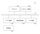
- FIG. 1 is a diagram illustrating an example of a hardware configuration of a wireless network design assistance device 10 according to an embodiment of the present invention.
- 1 is a diagram illustrating an example of a functional configuration of a wireless network design assistance device 10 according to an embodiment of the present invention.
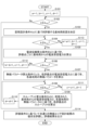
- 10 is a flowchart illustrating an example of a processing procedure of a wireless area design process according to the first embodiment.
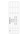
- FIG. 13 is a diagram showing an example of station placement design condition A.
- FIG. 13 is a diagram showing an example of radio wave propagation calculation condition B.
- FIG. 13 is a diagram showing an example of a wireless parameter calculation condition C.
- FIG. 13 is a diagram illustrating an example of a throughput calculation condition D.
- 13 is a flowchart illustrating an example of a processing procedure of a wireless area design process according to the second embodiment.
- FIG. 1 is a diagram showing an example of the hardware configuration of a wireless area design support device 10 in an embodiment of the present invention.
- the wireless area design support device 10 in FIG. 1 has a drive device 100, an auxiliary storage device 102, a memory device 103, a processor 104, and an interface device 105, which are all interconnected by a bus B.
- the program that realizes the processing in the wireless area design assistance device 10 is provided by a recording medium 101 such as a CD-ROM.
- a recording medium 101 such as a CD-ROM.
- the program is installed from the recording medium 101 via the drive device 100 into the auxiliary storage device 102.
- the program does not necessarily have to be installed from the recording medium 101, but may be downloaded from another computer via a network.
- the auxiliary storage device 102 stores the installed program as well as necessary files, data, etc.
- the memory device 103 When an instruction to start a program is received, the memory device 103 reads out and stores the program from the auxiliary storage device 102.
- the processor 104 is a CPU or a GPU (Graphics Processing Unit), or a CPU and a GPU, and executes functions related to the wireless area design support device 10 in accordance with the program stored in the memory device 103.
- the interface device 105 is used as an interface for connecting to a network.
- FIG. 2 is a diagram showing an example of the functional configuration of the wireless area design support device 10 in an embodiment of the present invention.
- the wireless area design support device 10 has a station placement design unit 11, a received power calculation unit 12, a wireless parameter calculation unit 13, a throughput calculation unit 14, and an evaluation unit 15. Each of these units is realized by a process in which one or more programs installed in the wireless area design support device 10 are executed by the processor 104.
- FIG. 3 is a flowchart for explaining an example of the processing procedure of the wireless area design process.
- station placement design refers to determining the placement of base stations (installation locations and antenna directions) to build the coverage area of the wireless system
- wireless area design refers to determining the wireless parameters (transmission output, channel, etc.) to be set for the base stations in addition to station placement design.
- step S101 the station design unit 11 assigns the value 1 to each of the variables a, b, c, and d.
- the station placement design unit 11 judges whether the value of a is equal to or smaller than a max (S102), where a max is the upper limit of a and is set in advance.
- the station placement design unit 11 determines the base station placement (layout of the base station) to be evaluated for the placement of the base station in the target area based on the station placement design condition A(a) (S103).
- the target area refers to the geographical range that is the target of the design of the wireless area.
- the station placement design condition is information indicating the constraint condition in the station placement design.
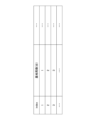
- FIG. 4 is a diagram showing an example of the station placement design condition A.
- the station placement design condition A includes a plurality of station placement design conditions.
- the above a max is the total number of station placement design conditions included in the station placement design condition A.
- the station placement design condition A(a) indicates the a-th station placement design condition (index is a) among the station placement design conditions A.
- the number of base stations is illustrated as an example of a component of the station placement design condition. That is, in FIG. 4, a plurality of base station conditions with different numbers of base stations are shown.
- the number of base stations is the number of base stations to be placed.
- the station placement design condition may include items other than the number of base stations.
- the station placement design condition may include items such as the orientation of the base station (antenna direction), the type of the system, information on the wireless base station device, the location where the wireless base station can be placed in the target area, the size and shape of the target area, the range (position) and material of the structure.
- the items that are effective in each station placement design condition may be different.
- the determination of base station placement based on station placement design conditions may be made based on publicly known technology.
- the received power calculation unit 12 judges whether the value of b is equal to or smaller than bmax (S104), where bmax is the upper limit of b and is set in advance.
- the received power calculation unit 12 calculates the radio wave received power from any one of the base stations for each of one or more evaluation points in the target area based on the radio wave propagation calculation condition B(b) (S105).
- An evaluation point refers to a point that is set in advance as a location in the target area where wireless communication is required to be possible. For example, a location where the terminal is expected to be used is set as the evaluation point.
- the reception power calculation unit 12 calculates the radio wave reception power from all base stations for each evaluation point and selects one of the radio wave reception powers.
- the radio wave reception power selected for a certain evaluation point may be, for example, the maximum value of the radio wave reception powers calculated for that evaluation point.
- a priority order may be set for the wireless communication methods, and one radio wave reception power that takes that priority order into consideration may be selected. By selecting one radio wave reception power for each evaluation point, a base station to connect to is selected for each evaluation point.
- the location of each base station in the target area is the location determined in step S103, which was last executed up to the current point in time.
- the radio wave propagation calculation conditions are conditions related to the method of calculating the radio wave reception power from the base station.
- radio wave propagation calculation condition B includes a plurality of radio wave propagation calculation methods.
- the above b max is the total number of radio wave propagation calculation methods included in radio wave propagation calculation condition B.
- Radio wave propagation calculation condition B(b) indicates the b-th (index is b) radio wave propagation calculation method among radio wave propagation calculation condition B.
- the wireless parameter calculation unit 13 judges whether the value of c is equal to or smaller than cmax (S106), where cmax is the upper limit of c and is set in advance.
- the wireless parameter calculation unit 13 calculates wireless parameters to be set for each base station based on the wireless parameter calculation condition C(c) and the (maximum value of) the radio wave reception power from the base station at each evaluation point (S107).
- Fig. 6 is a diagram showing an example of the radio parameter calculation condition C.
- the radio parameter calculation condition C includes a plurality of available channels.
- the above c max is the total number of available channels included in the radio parameter calculation condition C.
- the radio parameter calculation condition C(c) indicates the c-th available channel (with index c) among the radio parameter calculation condition C.
- the wireless parameter calculation unit 13 calculates the frequency channel to be assigned to each base station from the range of available channels indicated by the wireless parameter calculation condition C(c).
- the throughput calculation unit 14 judges whether the value of d is equal to or smaller than d max (S108), where d max is the upper limit of d and is set in advance.
- the throughput calculation unit 14 calculates an estimate of the throughput of the wireless link between each evaluation point and the base station to which the evaluation point is connected, based on the throughput calculation condition D(d), the radio wave reception power of each evaluation point, and the wireless parameters of each base station (S109).
- the throughput calculation condition D is a condition for calculating the estimate of the throughput.
- FIG. 7 is a diagram showing an example of a throughput calculation condition D.
- the throughput calculation condition D includes a plurality of conditions as conditions for calculating an estimated value of the throughput.
- the above d max is the total number of throughput calculation conditions included in the throughput calculation condition D.
- the throughput calculation condition D(d) indicates the d-th (index is d) throughput calculation condition among the throughput calculation conditions D.
- the throughput calculation condition includes "communication direction", “protocol", "traffic volume”, etc.
- the communication direction "upstream/downstream mixed" means that the estimated values of the throughput of each of the upstream and downstream are calculated when the upstream and downstream traffic are applied simultaneously.
- the "traffic volume” is the value of the traffic applied to the wireless link.
- the estimated value of the calculated throughput is the amount of data estimated to actually flow (for example, a value obtained by simulation).
- the throughput calculation unit 14 adds 1 to d (S110) and returns to step S108.
- the throughput calculation unit 14 adds 1 to c and assigns 1 to d (S111) and returns to step S106.
- the wireless parameter calculation unit 13 adds 1 to b and assigns 1 to c and d (S112) and returns to step S104.
- step S104 if the value of b exceeds b max (No in S104), the received power calculation unit 12 adds 1 to a and assigns 1 to b, c, and d (S113) and returns to step S102. As a result, if the value of a exceeds a max (No in S102), the process proceeds to step S114.
- radio area design result a combination (hereinafter referred to as "radio area design result") of base station placement results (S103), calculation results of radio wave reception power at each evaluation point (S105), calculation results of radio parameters of each base station (S107), and calculation results of estimated values of throughput at each evaluation point (S109) is obtained, and then step S114 is executed.
- the evaluation unit 15 evaluates the merits and demerits of all the wireless area design results based on the evaluation criteria E, and outputs the evaluation result.
- the evaluation criteria E refer to information for gradually narrowing down the base station arrangement results based on the following two conditions: (1) Communication quality satisfaction is equal to or greater than a target value (2) The total cost of the equipment is the smallest
- the communication quality satisfaction is an index showing the degree of satisfaction with a threshold value that is set in advance for the throughput for each evaluation point.
- the communication quality satisfaction may be determined as a value (a value between 0 and 1) obtained by dividing an estimated throughput value by the target value.
- the target value of the communication quality satisfaction is a threshold value that is set for the communication quality satisfaction.
- the total cost of the equipment may also be calculated based on, for example, a combination of the number of base stations and antennas required.
- the base station allocation results may be narrowed down based on only one of (1) and (2) above.
- the communication quality satisfaction level and the total cost of the equipment may be evaluated in stages by sequentially evaluating multiple conditions. For example, after narrowing down based on (1), one base station allocation result may be selected based on (2).
- the evaluation unit 15 outputs a set of wireless area design results (base station placement results, radio wave reception power, wireless parameters, and throughput estimates related to the base station placement results) selected based on (1) and (2) above.
- wireless area design can be efficiently performed based on the satisfaction level with respect to the communication quality target value and the equipment cost. In other words, it is possible to perform wireless area design taking into account communication quality or cost.
- FIG. 8 is a flowchart illustrating an example of the processing procedure for wireless area design processing in the second embodiment.
- step S201 the received power calculation unit 12 assigns 1 to the variable i.
- the reception power calculation unit 12 calculates a set (hereinafter referred to as a "base station candidate pattern") of multiple candidates (hereinafter referred to as “base station candidates”) for the placement position of the base station in the target area (S202). For example, if the target area is modeled in a rectangular shape, the reception power calculation unit 12 may calculate the coordinates of each candidate so that they are equally spaced in the x-axis (e.g., the axis on the long side) and y-axis (e.g., the axis on the short side) directions. Alternatively, the reception power calculation unit 12 may calculate the coordinates of each candidate randomly.
- x-axis e.g., the axis on the long side
- y-axis e.g., the axis on the short side
- the reception power calculation unit 12 may calculate the coordinates of each candidate randomly.
- the coordinates of each candidate may be calculated taking into account constraints on the placement of base stations in the target area (such as places where placement is not possible).
- the coordinates of each candidate may be calculated by other methods, or the coordinates of each candidate may be given values.
- the reception power calculation unit 12 calculates the radio wave reception power for each evaluation point in the target area when a base station is placed at each base station candidate (S203). Therefore, the radio wave reception power is calculated for each evaluation point as many as the number of base station candidates.
- the method of calculating the radio wave reception power at the evaluation point from the base station candidate may be the same as the method of calculating the radio wave reception power at the evaluation point from the base station in step S105 of FIG. 3.
- the radio wave reception power is calculated based on a predetermined radio wave propagation calculation condition that is set in advance.
- the radio wave propagation calculation condition may be any of the radio wave propagation calculation conditions that make up radio wave propagation calculation condition B, or it may not be any of them.
- the station placement design unit 11 judges whether the value of the variable i is equal to or smaller than imax (S204).
- imax is a preset upper limit value for the number of times to search for a wireless area design result that satisfies the target of communication quality satisfaction.
- the station placement design unit 11 determines the placement positions of the i base stations (layout of the i base stations) from the base station candidate pattern (S205). That is, the i base station candidates are selected as the placement destinations of the base stations.
- the selected base station candidates are referred to as "selected base station candidates”.
- a set of selected base station candidates is referred to as "base station placement result”. Note that the selection of the placement positions of the i base stations may be performed based on station placement design conditions A in which the number of base stations is i.
- the station design unit 11 determines one selected base station candidate (hereinafter referred to as a "destination candidate") to be connected to at that evaluation point (S206).
- the destination candidate for a certain evaluation point may be, for example, the selected base station candidate with the highest radio wave reception power calculated for that evaluation point.
- a priority order may be set for the wireless communication methods, and one selected base station candidate may be determined taking into consideration the priority order.
- the wireless parameter calculation unit 13 calculates wireless parameters for the base station related to each connection candidate based on one predetermined wireless parameter calculation condition set in advance and the radio wave reception power from the connection candidate at each evaluation point (S207).
- the predetermined wireless parameter calculation condition may be any of the wireless parameter calculation conditions C (FIG. 6) or other conditions.
- the throughput calculation unit 14 calculates an estimate of the throughput of the wireless link between each evaluation point and the base station related to the connection candidate based on a predetermined throughput calculation condition set in advance, the radio wave reception power of each evaluation point, and the wireless parameters of the base station related to each connection candidate (S208).
- the predetermined throughput calculation condition may be any of the conditions in the throughput calculation condition D (FIG. 7), or may be other conditions.
- the evaluation unit 15 calculates the communication quality satisfaction level for each evaluation point based on the estimated throughput value for each evaluation point (S209).
- the definition of the communication quality satisfaction level may be the same as in the first embodiment.
- the evaluation unit 15 determines whether the percentage of evaluation points at which the communication quality satisfaction level is equal to or greater than the target value is equal to or greater than a threshold value (S210). For example, if the threshold value is 100%, it is determined whether the communication quality satisfaction level is equal to or greater than the target value for all evaluation points.
- the evaluation unit 15 If the ratio of evaluation points for which the communication quality satisfaction is equal to or greater than the target value is equal to or greater than the threshold value (Yes in S210), the evaluation unit 15 outputs the current base station placement result, a combination of the radio wave reception power of each evaluation point, wireless parameters, and the estimated values of throughput as the wireless area design result (S212).
- step S204 and subsequent steps are executed again.
- the merits of wireless area designs based on multiple station placement results are evaluated based on equipment cost and communication quality satisfaction. In other words, the case with a smaller number of base stations is evaluated first (in the order of precedence), so the case with a lower equipment cost is evaluated higher.
- step S212 is not executed and the processing procedure in FIG. 8 ends.
- the wireless area design is not comprehensively searched, but it is possible to search for a wireless area design more efficiently than in the first embodiment. Also, like the first embodiment, it is possible to make a wireless area design that takes communication quality or cost into consideration.
Landscapes
- Engineering & Computer Science (AREA)
- Computer Networks & Wireless Communication (AREA)
- Signal Processing (AREA)
- Mobile Radio Communication Systems (AREA)
Abstract
無線エリア設計支援装置は、無線通信に関する基地局の配置について相互に基地局の数が異なる複数通りのレイアウトごとに、1以上の地点について、当該レイアウトに従って基地局が配置された場合の受信電力を算出する受信電力算出部と、前記レイアウトごとに、当該レイアウトに係る基地局に対して設定する無線パラメータを所定の条件に基づいて算出する無線パラメータ算出部と、前記レイアウトごとに、前記受信電力及び前記無線パラメータに基づいて、前記1以上の地点におけるスループットの推定値を算出するスループット算出部と、前記基地局の数及び前記推定値の少なくともいずれか一方に基づいて前記複数通りのレイアウトの優劣を評価する評価部と、を有することで、通信品質又はコストを考慮した無線エリア設計を可能とする。
Description
本発明は、無線エリア設計支援装置、無線エリア設計支援方法及びプログラムに関する。
無線通信システムのカバーエリア構築のため、基地局配置(設置場所やアンテナ方向)を決める置局設計が行われる。置局設計では、基地局配置を選定した上で、サービスエリアのシミュレーションを行うことがあり、実験式による推定(非特許文献1)や、レイトレーシング法(非特許文献2)などの方法が用いられる。
"移動通信における置局設計"、NTT DoCoMoテクニカルジャーナル vol.2 no.4、[online]、インターネット<https://www.nttdocomo.co.jp/binary/pdf/corporate/technology/rd/technical_journal/bn/vol2_4/vol2_4_035jp.pdf>
"電波伝搬推定のための遺伝的アルゴリズムを用いたレイトレーシング方"、NTT DoCoMoテクニカルジャーナル vol.15 no.3、[online]、インターネット<https://www.nttdocomo.co.jp/binary/pdf/corporate/technology/rd/technical_journal/bn/vol15_3/vol15_3_020jp.pdf>
無線システムの新たな利用形態として、工場等でのビジネス向けの利用拡大が今後見込まれている。コンシューマ向けのベストエフォート型サービスとは異なり、ビジネス向けサービスでは、要求する通信スループットを満たせるような無線エリア設計が求められると考えられるが、基地局配置を選定した上でサービスエリアのシミュレーションを行う従来技術では、要求する通信スループットを満たすか否かに基づいた無線基地局の置局設計を行えないことが課題となっていた。また、機器コストの考慮も行えなかった。
本発明は、上記の点に鑑みてなされたものであって、通信品質又はコストを考慮した無線エリア設計を可能とすることを目的とする。
そこで上記課題を解決するため、無線エリア設計支援装置は、無線通信に関する基地局の配置について相互に基地局の数が異なる複数通りのレイアウトごとに、1以上の地点について、当該レイアウトに従って基地局が配置された場合の受信電力を算出するように構成されている受信電力算出部と、前記レイアウトごとに、当該レイアウトに係る基地局に対して設定する無線パラメータを所定の条件に基づいて算出するように構成されている無線パラメータ算出部と、前記レイアウトごとに、前記受信電力及び前記無線パラメータに基づいて、前記1以上の地点におけるスループットの推定値を算出するように構成されているスループット算出部と、前記基地局の数及び前記推定値の少なくともいずれか一方に基づいて前記複数通りのレイアウトの優劣を評価するように構成されている評価部と、を有する。
通信品質又はコストを考慮した無線エリア設計を可能とすることができる。
以下、図面に基づいて本発明の実施の形態を説明する。図1は、本発明の実施の形態における無線エリア設計支援装置10のハードウェア構成例を示す図である。図1の無線エリア設計支援装置10は、それぞれバスBで相互に接続されているドライブ装置100、補助記憶装置102、メモリ装置103、プロセッサ104、及びインタフェース装置105等を有する。
無線エリア設計支援装置10での処理を実現するプログラムは、CD-ROM等の記録媒体101によって提供される。プログラムを記憶した記録媒体101がドライブ装置100にセットされると、プログラムが記録媒体101からドライブ装置100を介して補助記憶装置102にインストールされる。但し、プログラムのインストールは必ずしも記録媒体101より行う必要はなく、ネットワークを介して他のコンピュータよりダウンロードするようにしてもよい。補助記憶装置102は、インストールされたプログラムを格納すると共に、必要なファイルやデータ等を格納する。
メモリ装置103は、プログラムの起動指示があった場合に、補助記憶装置102からプログラムを読み出して格納する。プロセッサ104は、CPU若しくはGPU(Graphics Processing Unit)、又はCPU及びGPUであり、メモリ装置103に格納されたプログラムに従って無線エリア設計支援装置10に係る機能を実行する。インタフェース装置105は、ネットワークに接続するためのインタフェースとして用いられる。
図2は、本発明の実施の形態における無線エリア設計支援装置10の機能構成例を示す図である。図2において、無線エリア設計支援装置10は、置局設計部11、受信電力算出部12、無線パラメータ算出部13、スループット算出部14及び評価部15等を有する。これら各部は、無線エリア設計支援装置10にインストールされた1以上のプログラムが、プロセッサ104に実行させる処理により実現される。
以下、無線エリア設計支援装置10が実行する処理手順について説明する。図3は、無線エリア設計処理の処理手順の一例を説明するためのフローチャートである。なお、本実施の形態において、置局設計とは、無線システムのカバーエリア構築のため、基地局の配置(設置場所やアンテナ方向)を決めることをいい、無線エリア設計とは、置局設計に加えて基地局に対して設定される無線パラメータ(送信出力、チャネル等)を決めることをいう。
ステップS101において、置局設計部11は、変数a、b、c及びdのそれぞれに1を代入する。
続いて、置局設計部11は、aの値がamax以下であるか否かを判定する(S102)。amaxはaの上限値であり、予め設定される。
aの値がamax以下である場合(S102でYes)、置局設計部11は、置局設計条件A(a)に基づき、対象エリアに対する基地局の配置について、評価対象とする基地局配置(基地局のレイアウト)を決定する(S103)。対象エリアとは、無線エリアの設計の対象とされている地理的範囲をいう。また、置局設計条件とは、置局設計における制約条件を示す情報である。
図4は、置局設計条件Aの一例を示す図である。図4に示されるように、置局設計条件Aは、複数通りの置局設計条件を含む。上記のamaxは、置局設計条件Aが含む置局設計条件の総数である。置局設計条件A(a)とは、置局設計条件Aのうちa番目の(indexがaである)置局設計条件を示す。図4には、基地局台数が置局設計条件の構成要素として例示されている。すなわち、図4には、基地局台数が相互に異なる複数通りの基地局条件が示されている。基地局台数は、配置する基地局の数である。置局設計条件は、基地局台数以外の項目を含んでもよい。例えば、置局設計条件は、基地局の向き(アンテナの方向)、システムの種別、無線基地局装置の情報、対象エリア内で無線基地局を配置可能な場所、対象エリアの広さ及び形状、構造物の範囲(位置)及び材質等の項目を含んでもよい。これらの項目のうち、各置局設計条件において有効な項目が異なってもよい。
なお、置局設計条件に基づく(置局設計を満たす)基地局配置の決定は、公知技術に基づいて行われればよい。
続いて、受信電力算出部12は、bの値がbmax以下であるか否かを判定する(S104)。bmaxはbの上限値であり、予め設定される。
bの値がbmax以下である場合(S104でYes)、受信電力算出部12は、電波伝搬算出条件B(b)に基づき、対象エリアの1以上の評価点のそれぞれについていずれか1つの基地局からの電波受信電力を算する(S105)。評価点とは、対象エリアにおいて無線通信が可能であることが要求される場所として予め設定された地点をいう。例えば、端末の利用が想定される場所が評価点として設定される。
評価点ごとにいずれか1つの基地局からの電波受信電力が算出されるため、1つの評価点に対して1つの電波受信電力が算出される。例えば、受信電力算出部12は、評価点ごとに、全ての基地局からの電波受信電力を算出し、そのうちの1つの電波受信電力を選択する。或る評価点について選択される電波受信電力は、例えば、当該評価点について算出された電波受信電力のうちの最大値であってもよい。又は、基地局間において無線通信方式が混在している場合には、無線通信方式に優先順位を設け、当該優先順位が考慮された1つの電波受信電力が選択されてもよい。評価点ごとに1つの電波受信電力が選択されることで、評価点ごとに接続先の基地局が選択されることになる。
なお、電波受信電力の算出に際し、対象エリアにおける各基地局の配置位置は、現時点までで最後に実行されたステップS103において決定された配置位置である。また、電波伝搬算出条件とは、基地局からの電波受信電力の算出方法に関する条件である。
図5は、電波伝搬算出条件Bの一例を示す図である。図5に示されるように、電波伝搬算出条件Bは、複数通りの電波伝搬算出方法を含む。上記のbmaxは、電波伝搬算出条件Bが含む電波伝搬算出方法の総数である。電波伝搬算出条件B(b)とは、電波伝搬算出条件Bのうちb番目の(indexがbである)電波伝搬算出方法を示す。
続いて、無線パラメータ算出部13は、cの値がcmax以下であるか否かを判定する(S106)。cmaxはcの上限値であり、予め設定される。
cの値がcmax以下である場合(S106でYes)、無線パラメータ算出部13は、無線パラメータ算出条件C(c)と、各評価点における基地局からの電波受信電力(の最大値)とに基づき、各基地局に設定する無線パラメータを算出する(S107)。
図6は、無線パラメータ算出条件Cの一例を示す図である。図6に示されるように、無線パラメータ算出条件Cは、複数通りの利用可能チャネルを含む。上記のcmaxは、無線パラメータ算出条件Cが含む利用可能チャネルの総数である無線パラメータ算出条件C(c)とは、無線パラメータ算出条件Cのうちc番目の(indexがcである)利用可能チャネルを示す。
無線パラメータ算出部13は、無線パラメータ算出条件C(c)が示す利用可能チャネルの範囲の中から各基地局に割り当てる周波数チャネルを算出する。
続いて、スループット算出部14は、dの値がdmax以下であるか否かを判定する(S108)。dmaxはdの上限値であり、予め設定される。
dの値がdmax以下である場合(S108でYes)、スループット算出部14は、スループット算出条件D(d)と、各評価点の電波受信電力と、各基地局の無線パラメータとに基づき、各評価点について当該評価点の接続先の基地局との間の無線リンクのスループットの推定値を算出する(S109)。スループット算出条件Dとは、スループットの推定値を算出するための条件である。
図7は、スループット算出条件Dの一例を示す図である。図7に示されるように、スループット算出条件Dは、スループットの推定値を算出するための条件として複数通りの条件を含む。上記のdmaxは、スループット算出条件Dが含むスループット算出条件の総数であるスループット算出条件D(d)とは、スループット算出条件Dのうちd番目の(indexがdである)スループット算出条件を示す。図7の例において、スループット算出条件は、「通信方向」、「プロコトル」及び「トラヒック量」等を含む。ここで、通信方向が「上り・下り混在」とは、上りと下りのトラヒックを同時に印加した場合の上り、下りそれぞれのスループットの推定値を算出することを意味する。また、「トラヒック量」は、無線リンクに印加するトラヒックの値である。算出されるスループットの推定値は、実際に流れることが推定されるデータ量(例えば、シミュレーションによって得られる値)である。
続いて、スループット算出部14は、dに1を加算して(S110)、ステップS108へ戻る。その結果、dの値がdmaxを超えると(S108でNo)、スループット算出部14は、cに1を加算すると共にdに1を代入して(S111)、ステップS106へ戻る。その結果、cの値がcmaxを超えると(S106でNo)、無線パラメータ算出部13は、bに1を加算すると共にc及びdに1を代入して(S112)、ステップS104へ戻る。その結果、bの値がbmaxを超えると(S104でNo)、受信電力算出部12は、aに1を加算すると共にb、c及びdに1を代入して(S113)、ステップS102へ戻る。その結果、aの値がamaxを超えると(S102でNo)、ステップS114へ進む。すなわち、置局設計条件と、電波伝搬算出方法と、無線パラメータ算出条件と、スループット算出条件との全ての(全通りの)組み合わせについて、基地局配置結果(S103)、各評価点における電波受信電力の算出結果(S105)、各基地局の無線パラメータの算出結果(S107)、及び各評価点のスループットの推定値の算出結果(S109)の組み合わせ(以下、「無線エリア設計結果」という。)が得られた上で、ステップS114が実行される。
ステップS114において、評価部15は、評価条件Eに基づいて、全通りの無線エリア設計結果の優劣を評価し、評価結果を出力する。評価条件Eとは、以下2つの条件に基づいて基地局配置結果を段階的に絞り込むための情報をいう。
(1)通信品質満足度が目標値以上
(2)機器の合計コストが最小
ここで、通信品質満足度とは、評価点ごとにスループットに対して予め設定されている閾値に対する充足度合いを示す指標である。例えば、スループットの推定値を当該目標値によって除した値(0以上1以下の値)が通信品質満足度とされてもよい。通信品質満足度の目標値とは、通信品質満足度に対して設定されている閾値をいう。
(1)通信品質満足度が目標値以上
(2)機器の合計コストが最小
ここで、通信品質満足度とは、評価点ごとにスループットに対して予め設定されている閾値に対する充足度合いを示す指標である。例えば、スループットの推定値を当該目標値によって除した値(0以上1以下の値)が通信品質満足度とされてもよい。通信品質満足度の目標値とは、通信品質満足度に対して設定されている閾値をいう。
また、機器の合計コストは、例えば、必要となる基地局の数とアンテナの数の組み合わせに基づいて算出されてもよい。
なお、上記(1)及び(2)のうちのいずれか一方のみに基づいて基地局配置結果が絞り込まれてもよい。また、通信品質満足度や機器の合計コストは、複数条件を逐次的に評価することで、段階的に評価されてもよい。例えば、(1)に基づいて絞り込んだ後で、(2)に基づいて一つの基地局配置結果が選択されてもよい。
例えば、評価部15は、上記の(1)及び(2)に基づいて選択される1組の無線エリア設計結果(基地局配置結果、当該基地局配置結果に係る電波受信電力、無線パラメータ及びスループットの推定値)を出力する。
上述したように、第1の実施の形態によれば、通信品質目標値に対する満足度と機器コストに基づいた無線エリア設計を効率的に行うことができる。すなわち、通信品質又はコストを考慮した無線エリア設計を可能とすることができる。
次に、第2の実施の形態について説明する。第2の実施の形態では第1の実施の形態と異なる点について説明する。第2の実施の形態において特に言及されない点については、第1の実施の形態と同様でもよい。
図8は、第2の実施の形態における無線エリア設計処理の処理手順の一例を説明するためのフローチャートである。
ステップS201において、受信電力算出部12は、変数iに1を代入する。
続いて、受信電力算出部12は、対象エリアに対する基地局の配置位置に関する複数の候補(以下、「基地局候補」という。)の集合(以下、「基地局候補パタン」という。)を算出する(S202)。例えば、対象エリアが長方形の形状でモデル化されている場合であれば、受信電力算出部12は、x軸(例えば、長辺側の軸)及びy軸(例えば、短辺側の軸)方向にそれぞれ等間隔となるように、各候補の座標を算出してもよい。又は、受信電力算出部12は、ランダムに各候補の座標を算出してもよい。又は、対象エリアにおける基地局の配置に関する制約条件(配置不可能な場所等)が考慮されて各候補の座標が算出されてもよい。又は、他の方法によって各候補の座標が算出されてもよいし、各候補の座標は所与の値であってもよい。
続いて、受信電力算出部12は、対象エリアにおける評価点ごとに、各基地局候補に基地局が配置された場合の電波受信電力を算出する(S203)。したがって、1つの評価点に対し基地局候補数分の電波受信電力が算出される。なお、基地局候補からの評価点における電波受信電力の算出方法は、図3のステップS105における基地局からの評価点における電波受信電力の算出方法と同様でよい。但し、ここでは、予め設定された所定の1つの電波伝搬算出条件に基づいて電波受信電力が算出される。当該電波伝搬算出条件は、電波伝搬算出条件Bを構成するいずれかの電波伝搬算出条件であってもよいし、そうでなくてもよい。
続いて、置局設計部11は、変数iの値がimax以下であるか否かを判定する(S204)。imaxは、通信品質満足度の目標を満たす無線エリア設計結果を探索する回数の上限値であり、予め設定される。
変数iの値がimax以下である場合(S204でYes)、置局設計部11は、i台の基地局の配置位置(i台の基地局のレイアウト)を基地局候補パタンの中から決定する(S205)。すなわち、i個の基地局候補が基地局の配置先として選択される。以下、選択された基地局候補を「選択基地局候補」という。また、選択基地局候補の集合を「基地局配置結果」という。なお、i台の基地局の配置位置の選択は、置局設計条件Aの中で基地局数がi台である置局設計条件に基づいて行われてもよい。
続いて、置局設計部11は、評価点ごとに、当該評価点において接続先とする1つの選択基地局候補(以下、「接続先候補」という。)を決定する(S206)。或る評価点の接続先候補は、例えば、当該評価点について算出された電波受信電力が最大である選択基地局候補であってもよい。又は、基地局間において無線通信方式が混在している場合には、無線通信方式に優先順位を設け、当該優先順位が考慮されて1つの選択基地局候補が決定されてもよい。
続いて、無線パラメータ算出部13は、予め設定された所定の1つの無線パラメータ算出条件と、各評価点における接続先候補からの電波受信電力とに基づき、各接続先候補に係る基地局に対する無線パラメータを算出する(S207)。所定の無線パラメータ算出条件は、無線パラメータ算出条件C(図6)のうちのいずれかの無線パラメータ算出条件であってもよいし、他の条件であってもよい。
続いて、スループット算出部14は、予め設定された所定の1つのスループット算出条件と、各評価点の電波受信電力と、各接続先候補に係る基地局の無線パラメータとに基づき、各評価点について接続先候補に係る基地局との間の無線リンクのスループットの推定値を算出する(S208)。所定の1つのスループット算出条件は、スループット算出条件D(図7)のうちのいずれかの条件であってもよいし、他の条件であってもよい。
続いて、評価部15は、各評価点のスループットの推定値に基づいて、各評価点の通信品質満足度を算出する(S209)。通信品質満足度の定義は、第1の実施の形態と同様でよい。
続いて、評価部15は、通信品質満足度が目標値以上である評価点の割合が閾値以上であるか否かを判定する(S210)。例えば、当該閾値が100%であれば、全ての評価点において通信品質満足度が目標値以上であるか否かが判定される。
通信品質満足度が目標値以上である評価点の割合が閾値以上である場合(S210でYes)、評価部15は、現時点での基地局配置結果、各評価点の電波受信電力、無線パラメータ及びスループットの推定値の組み合わせを無線エリア設計結果として出力する(S212)。
通信品質満足度が目標値以上である評価点の割合が閾値未満である場合(S210でNo)、評価部15は、iに1を加算する(S211)。この場合、ステップS204以降が再実行される。ステップS204以降が繰り返されることで、複数通りの置局配置結果(相互に基地局の数が異なる複数通りのレイアウト)に基づく無線エリア設計について、機器コスト及び通信品質満足度に基づいて優劣が評価される。すなわち、基地局の数が少ない場合の方が優先して(先の順序で)評価されるため、機器コストが低い方が高く評価される。
ステップS204以降の繰り返しの結果、iがimaxを超えた場合(S211でNo)、ステップS212は実行されずに図8の処理手順は終了する。
上述したように、第2の実施の形態によれば、第1の実施の形態とは異なって網羅的に無線エリア設計は探索されないものの、第1の実施の形態に対して効率的に無線エリア設計を探索することができる。また、第1の実施の形態と同様に、通信品質又はコストを考慮した無線エリア設計を可能とすることができる。
なお、上記各実施の形態において、複数の無線システムや方式を混在させてもよい。
以上、本発明の実施の形態について詳述したが、本発明は斯かる特定の実施形態に限定されるものではなく、請求の範囲に記載された本発明の要旨の範囲内において、種々の変形・変更が可能である。
10 無線エリア設計支援装置
11 置局設計部
12 受信電力算出部
13 無線パラメータ算出部
14 スループット算出部
15 評価部
100 ドライブ装置
101 記録媒体
102 補助記憶装置
103 メモリ装置
104 プロセッサ
105 インタフェース装置
B バス
11 置局設計部
12 受信電力算出部
13 無線パラメータ算出部
14 スループット算出部
15 評価部
100 ドライブ装置
101 記録媒体
102 補助記憶装置
103 メモリ装置
104 プロセッサ
105 インタフェース装置
B バス
Claims (5)
- 無線通信に関する基地局の配置について相互に基地局の数が異なる複数通りのレイアウトごとに、1以上の地点について、当該レイアウトに従って基地局が配置された場合の受信電力を算出するように構成されている受信電力算出部と、
前記レイアウトごとに、当該レイアウトに係る基地局に対して設定する無線パラメータを所定の条件に基づいて算出するように構成されている無線パラメータ算出部と、
前記レイアウトごとに、前記受信電力及び前記無線パラメータに基づいて、前記1以上の地点におけるスループットの推定値を算出するように構成されているスループット算出部と、
前記基地局の数及び前記推定値の少なくともいずれか一方に基づいて前記複数通りのレイアウトの優劣を評価するように構成されている評価部と、
を有することを特徴とする無線エリア設計支援装置。 - 前記受信電力算出部は、前記レイアウトごとに、複数通りの条件に基づいて複数通りの前記受信電力を算出するように構成されており、
前記無線パラメータ算出部は、前記レイアウトごとに、複数通りの条件に基づいて複数通りの前記無線パラメータを算出するように構成されており、
前記スループット算出部は、前記レイアウトごとに、複数通りの条件に基づいて複数通りの前記推定値を算出するように構成されており、
前記評価部は、前記複数通りのレイアウト、前記複数通りの前記受信電力、前記複数通りの前記無線パラメータ、及び前記複数通りの前記推定値の組み合わせについて、前記優劣を評価するように構成されている、
ことを特徴とする請求項1記載の無線エリア設計支援装置。 - 前記無線パラメータは、周波数チャネルを含む、
ことを特徴とする請求項1又は2記載の無線エリア設計支援装置。 - 無線通信に関する基地局の配置について相互に基地局の数が異なる複数通りのレイアウトごとに、1以上の地点について、当該レイアウトに従って基地局が配置された場合の受信電力を算出する受信電力算出手順と、
前記レイアウトごとに、当該レイアウトに係る基地局に対して設定する無線パラメータを所定の条件に基づいて算出する無線パラメータ算出手順と、
前記レイアウトごとに、前記受信電力及び前記無線パラメータに基づいて、前記1以上の地点におけるスループットの推定値を算出するスループット算出手順と、
前記基地局の数及び前記推定値の少なくともいずれか一方に基づいて前記複数通りのレイアウトの優劣を評価する評価手順と、
をコンピュータが実行することを特徴とする無線エリア設計支援方法。 - 無線通信に関する基地局の配置について相互に基地局の数が異なる複数通りのレイアウトごとに、1以上の地点について、当該レイアウトに従って基地局が配置された場合の受信電力を算出する受信電力算出手順と、
前記レイアウトごとに、当該レイアウトに係る基地局に対して設定する無線パラメータを所定の条件に基づいて算出する無線パラメータ算出手順と、
前記レイアウトごとに、前記受信電力及び前記無線パラメータに基づいて、前記1以上の地点におけるスループットの推定値を算出するスループット算出手順と、
前記基地局の数及び前記推定値の少なくともいずれか一方に基づいて前記複数通りのレイアウトの優劣を評価する評価手順と、
をコンピュータに実行させることを特徴とするプログラム。
Priority Applications (2)
| Application Number | Priority Date | Filing Date | Title |
|---|---|---|---|
| PCT/JP2022/041707 WO2024100799A1 (ja) | 2022-11-09 | 2022-11-09 | 無線エリア設計支援装置、無線エリア設計支援方法及びプログラム |
| JP2024556917A JPWO2024100799A1 (ja) | 2022-11-09 | 2022-11-09 |
Applications Claiming Priority (1)
| Application Number | Priority Date | Filing Date | Title |
|---|---|---|---|
| PCT/JP2022/041707 WO2024100799A1 (ja) | 2022-11-09 | 2022-11-09 | 無線エリア設計支援装置、無線エリア設計支援方法及びプログラム |
Publications (1)
| Publication Number | Publication Date |
|---|---|
| WO2024100799A1 true WO2024100799A1 (ja) | 2024-05-16 |
Family
ID=91032572
Family Applications (1)
| Application Number | Title | Priority Date | Filing Date |
|---|---|---|---|
| PCT/JP2022/041707 Ceased WO2024100799A1 (ja) | 2022-11-09 | 2022-11-09 | 無線エリア設計支援装置、無線エリア設計支援方法及びプログラム |
Country Status (2)
| Country | Link |
|---|---|
| JP (1) | JPWO2024100799A1 (ja) |
| WO (1) | WO2024100799A1 (ja) |
Citations (4)
| Publication number | Priority date | Publication date | Assignee | Title |
|---|---|---|---|---|
| JP2013042202A (ja) * | 2011-08-11 | 2013-02-28 | Kddi Corp | 最適解検出装置及び最適解検出プログラム |
| WO2014073706A1 (ja) * | 2012-11-12 | 2014-05-15 | 日本電信電話株式会社 | 無線通信装置、無線通信システム及び無線通信方法 |
| JP2020120161A (ja) * | 2019-01-18 | 2020-08-06 | 日本電信電話株式会社 | 置局設計方法、置局設計装置、及びプログラム |
| JP2020170928A (ja) * | 2019-04-02 | 2020-10-15 | 日本電信電話株式会社 | 置局支援方法および置局支援システム |
-
2022
- 2022-11-09 JP JP2024556917A patent/JPWO2024100799A1/ja active Pending
- 2022-11-09 WO PCT/JP2022/041707 patent/WO2024100799A1/ja not_active Ceased
Patent Citations (4)
| Publication number | Priority date | Publication date | Assignee | Title |
|---|---|---|---|---|
| JP2013042202A (ja) * | 2011-08-11 | 2013-02-28 | Kddi Corp | 最適解検出装置及び最適解検出プログラム |
| WO2014073706A1 (ja) * | 2012-11-12 | 2014-05-15 | 日本電信電話株式会社 | 無線通信装置、無線通信システム及び無線通信方法 |
| JP2020120161A (ja) * | 2019-01-18 | 2020-08-06 | 日本電信電話株式会社 | 置局設計方法、置局設計装置、及びプログラム |
| JP2020170928A (ja) * | 2019-04-02 | 2020-10-15 | 日本電信電話株式会社 | 置局支援方法および置局支援システム |
Also Published As
| Publication number | Publication date |
|---|---|
| JPWO2024100799A1 (ja) | 2024-05-16 |
Similar Documents
| Publication | Publication Date | Title |
|---|---|---|
| Aljadhai et al. | Predictive mobility support for QoS provisioning in mobile wireless environments | |
| US8213942B2 (en) | Method for cognitive 4G neighborhood selection | |
| CN100551114C (zh) | 确定未知相邻小区的标识的方法,及其装置 | |
| Mahardhika et al. | Vertical handover decision algorithm using multicriteria metrics in heterogeneous wireless network | |
| KR101168212B1 (ko) | 이동전화 통신 네트워크 계획방법 | |
| Argyropoulos et al. | Dynamic channel allocation in interference-limited cellular systems with uneven traffic distribution | |
| JPWO2013061586A1 (ja) | スペクトル制御システム、データベース、スペクトル制御方法及びスペクトル制御プログラム | |
| Ghaderi et al. | Call admission control for voice/data integration, in. broadband, wireless networks | |
| US11956643B2 (en) | Station placement designing method, station placement designing apparatus and program | |
| Sarubbi et al. | A genetic algorithm for deploying roadside units in vanets | |
| Moltchanov et al. | Performance characterization and traffic protection in street multi-band millimeter-wave and microwave deployments | |
| Lee et al. | A probabilistic call admission control algorithm for WLAN in heterogeneous wireless environment | |
| Kobayashi et al. | Towards sustainable heterogeneous wireless networks: A decision strategy for AP selection with dynamic graphs | |
| Hwang et al. | Communication and computation offloading for 5G V2X: Modeling and optimization | |
| JP7521621B2 (ja) | 基地局配置支援装置、基地局配置支援方法及びプログラム | |
| JP6751069B2 (ja) | 無線リソース設計装置、無線リソース設計方法、及びプログラム | |
| EP2519058A1 (en) | Method for attaching a user terminal to a base station of a network | |
| CN108064051B (zh) | 确定网络射频优化方案的方法、装置及设备 | |
| US7840219B2 (en) | Radio station site in a telecommunications network | |
| Riaz et al. | A novel white space optimization scheme using memory enabled genetic algorithm in cognitive vehicular communication | |
| KR102414691B1 (ko) | 무선망 최적화 방법 및 이를 위한 관리서버 | |
| Cai et al. | Incentive mechanism design for delayed WiFi offloading | |
| Shi | Evaluating the performability of tactical communications networks | |
| WO2024150426A1 (ja) | 置局設計支援装置、置局設計支援方法及びプログラム | |
| US12506675B2 (en) | Control system, network control method and program |
Legal Events
| Date | Code | Title | Description |
|---|---|---|---|
| 121 | Ep: the epo has been informed by wipo that ep was designated in this application |
Ref document number: 22965124 Country of ref document: EP Kind code of ref document: A1 |
|
| WWE | Wipo information: entry into national phase |
Ref document number: 2024556917 Country of ref document: JP |
|
| NENP | Non-entry into the national phase |
Ref country code: DE |
|
| 122 | Ep: pct application non-entry in european phase |
Ref document number: 22965124 Country of ref document: EP Kind code of ref document: A1 |