WO2024096657A1 - 통신 시스템에서 혼잡 정보를 제공하는 장치 및 방법 - Google Patents
통신 시스템에서 혼잡 정보를 제공하는 장치 및 방법 Download PDFInfo
- Publication number
- WO2024096657A1 WO2024096657A1 PCT/KR2023/017478 KR2023017478W WO2024096657A1 WO 2024096657 A1 WO2024096657 A1 WO 2024096657A1 KR 2023017478 W KR2023017478 W KR 2023017478W WO 2024096657 A1 WO2024096657 A1 WO 2024096657A1
- Authority
- WO
- WIPO (PCT)
- Prior art keywords
- ran
- entity
- congestion
- ecn
- information
- Prior art date
Links
- 238000000034 method Methods 0.000 title claims abstract description 108
- 238000004891 communication Methods 0.000 title claims abstract description 93
- 230000004913 activation Effects 0.000 claims abstract description 7
- 230000005540 biological transmission Effects 0.000 abstract description 39
- 230000006870 function Effects 0.000 description 198
- 238000007726 management method Methods 0.000 description 78
- 238000012545 processing Methods 0.000 description 71
- 230000008569 process Effects 0.000 description 48
- 238000010586 diagram Methods 0.000 description 41
- 238000005516 engineering process Methods 0.000 description 30
- 230000004044 response Effects 0.000 description 22
- 238000010295 mobile communication Methods 0.000 description 21
- 238000012986 modification Methods 0.000 description 21
- 230000004048 modification Effects 0.000 description 21
- 238000011144 upstream manufacturing Methods 0.000 description 18
- 238000002360 preparation method Methods 0.000 description 10
- 230000011664 signaling Effects 0.000 description 10
- 230000003139 buffering effect Effects 0.000 description 9
- 238000005259 measurement Methods 0.000 description 9
- 230000008859 change Effects 0.000 description 8
- 238000004590 computer program Methods 0.000 description 8
- 238000013473 artificial intelligence Methods 0.000 description 7
- 238000012384 transportation and delivery Methods 0.000 description 6
- 230000001413 cellular effect Effects 0.000 description 5
- 230000008901 benefit Effects 0.000 description 3
- 238000012508 change request Methods 0.000 description 3
- 238000012790 confirmation Methods 0.000 description 3
- 238000001514 detection method Methods 0.000 description 3
- 238000011161 development Methods 0.000 description 3
- 230000009977 dual effect Effects 0.000 description 3
- 230000002441 reversible effect Effects 0.000 description 3
- 241000760358 Enodes Species 0.000 description 2
- 238000003491 array Methods 0.000 description 2
- 230000010267 cellular communication Effects 0.000 description 2
- 230000007423 decrease Effects 0.000 description 2
- 238000002716 delivery method Methods 0.000 description 2
- 238000013461 design Methods 0.000 description 2
- 238000001914 filtration Methods 0.000 description 2
- 230000006872 improvement Effects 0.000 description 2
- 238000007689 inspection Methods 0.000 description 2
- 230000002452 interceptive effect Effects 0.000 description 2
- 238000010801 machine learning Methods 0.000 description 2
- 238000012544 monitoring process Methods 0.000 description 2
- 238000013468 resource allocation Methods 0.000 description 2
- 238000000926 separation method Methods 0.000 description 2
- 238000003860 storage Methods 0.000 description 2
- 206010042135 Stomatitis necrotising Diseases 0.000 description 1
- 238000004458 analytical method Methods 0.000 description 1
- 230000003190 augmentative effect Effects 0.000 description 1
- 238000013475 authorization Methods 0.000 description 1
- 230000006399 behavior Effects 0.000 description 1
- 239000000969 carrier Substances 0.000 description 1
- 230000006835 compression Effects 0.000 description 1
- 238000007906 compression Methods 0.000 description 1
- 238000013523 data management Methods 0.000 description 1
- 238000013506 data mapping Methods 0.000 description 1
- 238000013500 data storage Methods 0.000 description 1
- 238000005315 distribution function Methods 0.000 description 1
- 239000002360 explosive Substances 0.000 description 1
- 230000014509 gene expression Effects 0.000 description 1
- 230000036541 health Effects 0.000 description 1
- 239000003999 initiator Substances 0.000 description 1
- 230000003993 interaction Effects 0.000 description 1
- 239000004973 liquid crystal related substance Substances 0.000 description 1
- 230000007774 longterm Effects 0.000 description 1
- 238000012423 maintenance Methods 0.000 description 1
- 238000013507 mapping Methods 0.000 description 1
- 239000003550 marker Substances 0.000 description 1
- 230000006855 networking Effects 0.000 description 1
- 201000008585 noma Diseases 0.000 description 1
- 238000011017 operating method Methods 0.000 description 1
- 238000005457 optimization Methods 0.000 description 1
- 230000000737 periodic effect Effects 0.000 description 1
- 238000007781 pre-processing Methods 0.000 description 1
- 230000009467 reduction Effects 0.000 description 1
- 230000001105 regulatory effect Effects 0.000 description 1
- 238000009877 rendering Methods 0.000 description 1
- 238000011160 research Methods 0.000 description 1
- 238000005728 strengthening Methods 0.000 description 1
- 230000001960 triggered effect Effects 0.000 description 1
- 238000012795 verification Methods 0.000 description 1
Images


Classifications
-
- H—ELECTRICITY
- H04—ELECTRIC COMMUNICATION TECHNIQUE
- H04W—WIRELESS COMMUNICATION NETWORKS
- H04W36/00—Hand-off or reselection arrangements
- H04W36/0005—Control or signalling for completing the hand-off
- H04W36/0011—Control or signalling for completing the hand-off for data sessions of end-to-end connection
- H04W36/0033—Control or signalling for completing the hand-off for data sessions of end-to-end connection with transfer of context information
-
- H—ELECTRICITY
- H04—ELECTRIC COMMUNICATION TECHNIQUE
- H04L—TRANSMISSION OF DIGITAL INFORMATION, e.g. TELEGRAPHIC COMMUNICATION
- H04L47/00—Traffic control in data switching networks
- H04L47/10—Flow control; Congestion control
- H04L47/11—Identifying congestion
-
- H—ELECTRICITY
- H04—ELECTRIC COMMUNICATION TECHNIQUE
- H04L—TRANSMISSION OF DIGITAL INFORMATION, e.g. TELEGRAPHIC COMMUNICATION
- H04L47/00—Traffic control in data switching networks
- H04L47/10—Flow control; Congestion control
- H04L47/11—Identifying congestion
- H04L47/115—Identifying congestion using a dedicated packet
-
- H—ELECTRICITY
- H04—ELECTRIC COMMUNICATION TECHNIQUE
- H04L—TRANSMISSION OF DIGITAL INFORMATION, e.g. TELEGRAPHIC COMMUNICATION
- H04L47/00—Traffic control in data switching networks
- H04L47/10—Flow control; Congestion control
- H04L47/19—Flow control; Congestion control at layers above the network layer
-
- H—ELECTRICITY
- H04—ELECTRIC COMMUNICATION TECHNIQUE
- H04L—TRANSMISSION OF DIGITAL INFORMATION, e.g. TELEGRAPHIC COMMUNICATION
- H04L47/00—Traffic control in data switching networks
- H04L47/10—Flow control; Congestion control
- H04L47/20—Traffic policing
-
- H—ELECTRICITY
- H04—ELECTRIC COMMUNICATION TECHNIQUE
- H04L—TRANSMISSION OF DIGITAL INFORMATION, e.g. TELEGRAPHIC COMMUNICATION
- H04L47/00—Traffic control in data switching networks
- H04L47/10—Flow control; Congestion control
- H04L47/26—Flow control; Congestion control using explicit feedback to the source, e.g. choke packets
- H04L47/263—Rate modification at the source after receiving feedback
-
- H—ELECTRICITY
- H04—ELECTRIC COMMUNICATION TECHNIQUE
- H04W—WIRELESS COMMUNICATION NETWORKS
- H04W28/00—Network traffic management; Network resource management
- H04W28/02—Traffic management, e.g. flow control or congestion control
-
- H—ELECTRICITY
- H04—ELECTRIC COMMUNICATION TECHNIQUE
- H04W—WIRELESS COMMUNICATION NETWORKS
- H04W28/00—Network traffic management; Network resource management
- H04W28/02—Traffic management, e.g. flow control or congestion control
- H04W28/0284—Traffic management, e.g. flow control or congestion control detecting congestion or overload during communication
-
- H—ELECTRICITY
- H04—ELECTRIC COMMUNICATION TECHNIQUE
- H04W—WIRELESS COMMUNICATION NETWORKS
- H04W36/00—Hand-off or reselection arrangements
-
- H—ELECTRICITY
- H04—ELECTRIC COMMUNICATION TECHNIQUE
- H04W—WIRELESS COMMUNICATION NETWORKS
- H04W36/00—Hand-off or reselection arrangements
- H04W36/14—Reselecting a network or an air interface
Definitions
- This disclosure relates to an apparatus and method for providing congestion information in a communication system.
- the 5G communication system or pre-5G communication system is called a Beyond 4G Network communication system or a Post LTE system.
- 5G communication systems are being considered for implementation in ultra-high frequency (mmWave) bands (such as the 60 GHz band).
- mmWave ultra-high frequency
- the 5G communication system uses beamforming, massive array multiple input/output (massive MIMO), and full dimensional multiple input/output (FD-MIMO). ), array antenna, analog beam-forming, and large scale antenna technologies are being discussed.
- the 5G communication system uses advanced small cells, advanced small cells, cloud radio access networks (cloud RAN), and ultra-dense networks.
- D2D Device to Device communication
- wireless backhaul moving network
- cooperative communication CoMP (Coordinated Multi-Points)
- interference cancellation Technology development is underway.
- the 5G system uses advanced coding modulation (ACM) methods such as FQAM (Hybrid FSK and QAM Modulation) and SWSC (Sliding Window Superposition Coding), and advanced access technologies such as FBMC (Filter Bank Multi Carrier) and NOMA. (non orthogonal multiple access), and SCMA (sparse code multiple access) are being developed.
- ACM advanced coding modulation
- 3GPP which is in charge of cellular mobile communication standards, has named a new Core Network structure as 5G Core (5GC) and is standardizing it in order to evolve from the existing 4G LTE system to a 5G system.
- 5GC 5G Core
- 5GC supports the following differentiated functions compared to the Evolved Packet Core (EPC), the existing network core for 4G.
- EPC Evolved Packet Core
- 5GC the Network Slice function is introduced.
- 5GC must support a variety of terminal types and services; e.g., enhanced Mobile Broadband (eMBB), Ultra Reliable Low Latency Communications (URLLC), massive Machine Type Communications (mMTC).
- eMBB enhanced Mobile Broadband
- URLLC Ultra Reliable Low Latency Communications
- mMTC massive Machine Type Communications
- eMBB service requires a high data rate
- URLLC service requires high stability and low delay.
- the proposed technology to satisfy these various service requirements is the Network Slice method.
- Network Slice is a method of creating multiple logical networks by virtualizing one physical network, and each Network Slice Instance (NSI) can have different characteristics. Therefore, each NSI can satisfy various service requirements by having a network function (NF) suitable for its characteristics. Multiple 5G services can be efficiently supported by allocating an NSI that matches the characteristics of the service required for each terminal.
- NNI Network Slice Instance
- 5GC can facilitate network virtualization paradigm support through separation of mobility management function and session management function.
- MME Mobility Management Entity
- all terminals were able to receive services from the network through signaling exchange with a single core device called the Mobility Management Entity (MME), which is responsible for registration, authentication, mobility management, and session management functions.
- MME Mobility Management Entity
- scalability adding entities for each required function
- Scalability is bound to decline. Therefore, various functions are being developed based on a structure that separates the mobility management function and session management function to improve scalability in terms of signaling load and functional/implementation complexity of the core equipment responsible for the control plane.
- L4S low latency, low loss and scalable throughput
- ECN express congestion notification
- an apparatus and method for providing congestion information in a communication system may be provided.
- an apparatus and method for providing congestion information based on whether L4S (ECN) is supported in a communication system may be provided.
- an apparatus and method for handling congestion information at the changing base station based on whether or not L4S (ECN) is supported may be provided.
- a method is performed by a session management function (SMF) entity in a communication system, the method comprising: a source radio access network (S-RAN) of a terminal; ), the ECN (explicit congestion notification) marking function for the L4S (low latency, low loss and scalable throughput) service is activated, but the ECN for the L4S is activated in the target RAN (T-RAN) of the terminal. identifying that the marking function is not activated, and identifying that the ECN marking function for the L4S service in the S-RAN is activated, but the ECN marking function for the L4S in the T-RAN is not activated. , including transmitting information requesting to activate the ECN marking function for the L4S to a user plane function (UPF) entity.
- UPF user plane function
- a session management function (SMF) entity in a communication system, wherein the SMF entity includes a transceiver and at least one processor, wherein the at least one processor includes a terminal.
- the explicit congestion notification (ECN) marking function for L4S (low latency, low loss and scalable throughput) service is activated in the source radio access network (S-RAN), but the target RAN of the terminal Identify that the ECN marking function for the L4S in (target RAN: T-RAN) is not activated, and that the ECN marking function for the L4S service in the S-RAN is activated, but in the T-RAN to the L4S Based on identifying that the ECN marking function for the L4S is not activated, it is configured to transmit, through the transceiver, information requesting to activate the ECN marking function for the L4S to a user plane function (UPF) entity.
- UPF user plane function
- a user plane function (UPF) entity in a communication system, wherein the UPF entity includes a transceiver, and at least one processor, wherein the at least one processor includes: Through the transceiver, explicit congestion notification (ECN) marking for low latency, low loss and scalable throughput (L4S) service from the session management function (SMF) entity to the user plane function (UPF) entity. marking) function, and the information requesting to activate the ECN marking function for the L4S is transmitted from the source radio access network (S-RAN) of the terminal to the L4S.
- ECN explicit congestion notification
- SMF session management function
- S-RAN source radio access network
- An operation method of an access and mobility management function (AMF) entity comprising: transmitting a signal from a source radio access network (S-RAN) of a terminal to an L4S in the S-RAN; (low latency, low loss and scalable throughput)
- SMF source radio access network
- PDU protocol data unit
- SM session session management
- a method of operating a radio access network (RAN) in a communication system comprising: determining handover of a terminal, and an access and mobility management function (access) and mobility management function (AMF) entity, and includes an operation of transmitting a handover required message containing information related to whether L4S (low latency, low loss and scalable throughput) service is supported.
- RAN radio access network
- AMF mobility management function
- an access and mobility management function (AMF) entity is provided in a communication system, the AMF entity comprising a transceiver and at least one processor, the at least one processor Through the transceiver, information related to whether L4S (low latency, low loss and scalable throughput) service is supported in the S-RAN from the source radio access network (S-RAN) of the terminal.
- S-RAN source radio access network
- SMF session management function
- the transceiver It is configured to receive a PDU session SM update response message from the SMF entity.
- PDU protocol data unit
- SM session session management
- a radio access network in a communication system, the RAN includes a transceiver and at least one processor, and the at least one processor performs handover of the terminal.
- a hand that determines and includes information related to whether a low latency, low loss and scalable throughput (L4S) service is supported with an access and mobility management function (AMF) entity, through the transceiver. It is configured to send a handover required message.
- L4S low latency, low loss and scalable throughput
- AMF access and mobility management function
- the base station when the base station is changed due to the movement of the terminal and the changed base station does not support L4S (ECN) marking for in-band signaling, separate congestion situation information is sent to the control plane. is transmitted to the session management function (SMF) entity, and the SMF entity transmits congestion occurrence information to the user plane function (UPF) entity and performs L4S (ECN) marking on the UPF entity.
- SMF session management function
- UPF user plane function
- ECN L4S marking on the UPF entity.
- AS application server
- AS application server
- the UPF entity does not support L4S (ECN) marking because it is impossible to transmit congestion information from the changed base station to the control plane to the SMF entity due to various reasons such as operator policy, etc.
- the changed base station uses the SMF entity.
- QoS quality of service
- FIG. 1 is a diagram illustrating the network structure and interface of a 5G system according to an embodiment of the present disclosure.
- FIG. 2 is a diagram illustrating an operation when applying L4S/ECN marking in RAN in a wireless communication system according to an embodiment of the present disclosure.
- FIG. 3 is a diagram illustrating an issue that may occur when a terminal moves to a RAN that does not support congestion header marking in a wireless communication system according to an embodiment of the present disclosure.
- FIG. 4 is a diagram illustrating an Explicit Congestion Notification (ECN) bit in the TOS (Type Of Service) field of an IP header according to an embodiment of the present disclosure.
- ECN Explicit Congestion Notification
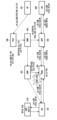
- Figure 5 shows that when the RAN does not support the L4S/ECN marking function according to an embodiment of the present disclosure, a congestion information report is transmitted to the SMF entity on the control plane, and the SMF entity transmits the congestion information to the UPF entity to perform L4S/ECN marking.
- This diagram illustrates the operation of performing ECN marking.
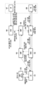
- FIG. 6 shows that L4S support information and related requirements are transmitted from an AF entity to a PCF entity for an L4S service in a communication system according to an embodiment of the present disclosure, and the L4S support information and related requirements are communicated with the RAN through a policy update step.
- This diagram illustrates the policy reflection for L4S/ECN marking in the UPF entity and the L4S service setup steps between the UE, AS, and 5G core network.
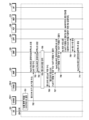
- FIG. 7A is a signal flow diagram schematically showing the operation of the handover preparation step in the N2-based NG-RAN handover method according to UE movement in a communication system according to an embodiment of the present disclosure.
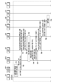
- Figures 7b and 7c are signal flow diagrams schematically showing the operation of the handover preparation stage in the N2-based NG-RAN handover method according to UE movement in a communication system according to an embodiment of the present disclosure.
- FIGS. 7D and 7E are signal flow diagrams schematically showing operations when a congestion situation occurs after handover is performed due to a terminal movement in a communication system according to an embodiment of the present disclosure.
- 7F, 7G, and 7H show L4S/ECN marking by transmitting congestion occurrence information to the UPF entity on the control plane when a congestion situation occurs after executing handover due to UE movement in a communication system according to an embodiment of the present disclosure.
- FIGS. 8A, 8B, and 8C are signal flow diagrams schematically showing an Xn-based handover process from Source-RAN to Target-RAN according to movement of a terminal in a communication system according to an embodiment of the present disclosure.
- FIG. 9 is a diagram schematically showing an example of the structure of a network entity according to an embodiment of the present disclosure.
- FIG. 10 is a diagram schematically showing an example of the structure of a terminal according to an embodiment of the present disclosure.
- Figure 11 is a block diagram schematically showing another example of the structure of a terminal according to an embodiment of the present disclosure.
- FIG. 12 is a block diagram schematically showing another example of the structure of a network entity according to an embodiment of the present disclosure.
- a base station is an entity that performs resource allocation for a terminal, such as gNode B, eNode B, Node B, (or xNode B (where x is an alphabet including g and e)), a wireless access unit. , it may be at least one of a base station controller, a satellite, an airborn, or a node on a network.
- Terminal user equipment: UE
- MS Mobile Station
- vehicle satellite, airborn, cellular phone, smartphone, computer, or multimedia system capable of performing communication functions. You can.
- downlink refers to the wireless transmission path of a signal transmitted from a base station to a terminal
- uplink refers to a wireless transmission path of a signal transmitted from a terminal to a base station
- SL sidelink
- LTE, LTE-A or 5G system may be described below as an example, embodiments of the present disclosure can also be applied to other communication systems with similar technical background or channel type.
- this may include 5G-Advance or NR-Advance or the 6th generation mobile communication technology (6G) developed after 5G mobile communication technology (or new radio, NR), and 5G hereinafter refers to existing LTE, LTE- It may be a concept that includes A and other similar services.
- this disclosure may be applied to other communication systems through some modifications without significantly departing from the scope of the present disclosure at the discretion of a person with skilled technical knowledge.
- each block of the processing flow diagrams and combinations of the flow diagram diagrams can be performed by computer program instructions.
- These computer program instructions can be mounted on a processor of a general-purpose computer, special-purpose computer, or other programmable data processing equipment, so that the instructions performed through the processor of the computer or other programmable data processing equipment are described in the flow chart block(s). It creates the means to perform functions.
- These computer program instructions may also be stored in computer-usable or computer-readable memory that can be directed to a computer or other programmable data processing equipment to implement a function in a particular manner, so that the computer-usable or computer-readable memory
- the instructions stored in may also produce manufactured items containing instruction means that perform the functions described in the flow diagram block(s).
- Computer program instructions can also be mounted on a computer or other programmable data processing equipment, so that a series of operational steps are performed on the computer or other programmable data processing equipment to create a process that is executed by the computer, thereby generating a process that is executed by the computer or other programmable data processing equipment. Instructions that perform processing equipment may also provide steps for executing the functions described in the flow diagram block(s).
- each block may represent a module, segment, or portion of code that includes one or more executable instructions for executing specified logical function(s).
- each block may represent a module, segment, or portion of code that includes one or more executable instructions for executing specified logical function(s).
- the term ' ⁇ unit' used in this embodiment refers to software or hardware components such as FPGA (Field Programmable Gate Array) or ASIC (Application Specific Integrated Circuit), and ' ⁇ unit' performs certain roles. do.
- ' ⁇ part' is not limited to software or hardware.
- the ' ⁇ part' may be configured to reside in an addressable storage medium and may be configured to reproduce on one or more processors. Therefore, as an example, ' ⁇ part' refers to components such as software components, object-oriented software components, class components, and task components, processes, functions, properties, and procedures. , subroutines, segments of program code, drivers, firmware, microcode, circuitry, data, databases, data structures, tables, arrays, and variables.
- components and 'parts' may be combined into a smaller number of components and 'parts' or may be further separated into additional components and 'parts'. Additionally, components and 'parts' may be implemented to regenerate one or more CPUs within a device or a secure multimedia card. Additionally, in an embodiment, ' ⁇ part' may include one or more processors.
- Wireless communication systems have moved away from providing early voice-oriented services to, for example, 3GPP's HSPA (High Speed Packet Access), LTE (Long Term Evolution or E-UTRA (Evolved Universal Terrestrial Radio Access)), and LTE-Advanced.
- Broadband wireless that provides high-speed, high-quality packet data services such as communication standards such as (LTE-A), LTE-Pro, 3GPP2's High Rate Packet Data (HRPD), UMB (Ultra Mobile Broadband), and IEEE's 802.16e. It is evolving into a communication system.
- the LTE system adopts Orthogonal Frequency Division Multiplexing (OFDM) in the downlink (DL), and Single Carrier Frequency Division Multiplexing (SC-FDMA) in the uplink (UL). Access) method is adopted.
- OFDM Orthogonal Frequency Division Multiplexing
- SC-FDMA Single Carrier Frequency Division Multiplexing
- Uplink refers to a wireless link through which a terminal transmits data or control signals to a base station
- downlink refers to a wireless link through which a base station transmits data or control signals to a terminal.
- the above multiple access method usually distinguishes each user's data or control information by allocating and operating the time-frequency resources to carry data or control information for each user so that they do not overlap, that is, orthogonality is established. You can.
- the 5G communication system must be able to freely reflect the various requirements of users and service providers, so services that simultaneously satisfy various requirements must be supported.
- Services considered for the 5G communication system include enhanced Mobile Broadband (eMBB), massive Machine Type Communication (mMTC), and Ultra Reliability Low Latency Communication (URLLC). There is.
- eMBB aims to provide more improved data transmission speeds than those supported by existing LTE, LTE-A or LTE-Pro.
- eMBB in a 5G communication system, eMBB must be able to provide a peak data rate of 20Gbps in the downlink and 10Gbps in the uplink from the perspective of one base station.
- the 5G communication system must provide the maximum transmission rate and at the same time provide increased user perceived data rate.
- improvements in various transmission and reception technologies are required, including more advanced multi-antenna (Multi Input Multi Output, MIMO) transmission technology.
- MIMO Multi Input Multi Output
- the 5G communication system uses a frequency bandwidth wider than 20MHz in the 3 ⁇ 6GHz or above 6GHz frequency band to transmit the data required by the 5G communication system. Transmission speed can be satisfied.
- mMTC is being considered to support application services such as the Internet of Things (IoT) in 5G communication systems.
- IoT Internet of Things
- mMTC requires support for access to a large number of terminals within a cell, improved coverage of terminals, improved battery time, and reduced terminal costs.
- the Internet of Things provides communication functions by attaching various sensors and various devices, it must be able to support a large number of terminals (for example, 1,000,000 terminals/km 2 ) within a cell. Due to the nature of the service, terminals supporting mMTC are likely to be located in shaded areas that cannot be covered by cells, such as the basement of a building, so they may require wider coverage than other services provided by the 5G communication system. Terminals that support mMTC must be composed of low-cost terminals, and since it is difficult to frequently replace the terminal's battery, a very long battery life time, such as 10 to 15 years, may be required.
- URLLC is a cellular-based wireless communication service used for a specific purpose (mission-critical). For example, remote control of robots or machinery, industrial automation, unmanned aerial vehicles, remote health care, and emergency situations. Services used for emergency alerts, etc. can be considered. Therefore, the communication provided by URLLC must provide very low latency and very high reliability. For example, a service that supports URLLC must satisfy an air interface latency of less than 0.5 milliseconds and has a packet error rate of less than 10-5. Therefore, for services that support URLLC, the 5G system must provide a smaller Transmit Time Interval (TTI) than other services, and at the same time, it is a design that must allocate wide resources in the frequency band to ensure the reliability of the communication link. Specifications may be required.
- TTI Transmit Time Interval
- the three services of 5G namely eMBB, URLLC, and mMTC, can be multiplexed and transmitted in one system. At this time, different transmission/reception techniques and transmission/reception parameters can be used between services to satisfy the different requirements of each service.
- 5G is not limited to the three services mentioned above.
- 5G mobile communication technology defines a wide frequency band to enable fast transmission speeds and new services, and includes sub-6 GHz ('Sub 6GHz') bands such as 3.5 gigahertz (3.5 GHz) as well as millimeter wave (mm) bands such as 28 GHz and 39 GHz. It is also possible to implement it in the ultra-high frequency band ('Above 6GHz') called Wave.
- 'Sub 6GHz' sub-6 GHz
- mm millimeter wave
- Wave ultra-high frequency band
- 6G mobile communication technology which is called the system of Beyond 5G
- Terra is working to achieve a transmission speed that is 50 times faster than 5G mobile communication technology and an ultra-low delay time that is reduced to one-tenth. Implementation in Terahertz bands (e.g., 95 GHz to 3 THz) is being considered.
- ultra-wideband services enhanced Mobile BroadBand, eMBB
- ultra-reliable low-latency communications URLLC
- massive machine-type communications mMTC
- numerology support multiple subcarrier interval operation, etc.
- dynamic operation of slot format initial access technology to support multi-beam transmission and broadband
- definition and operation of BWP Band-Width Part
- New channel coding methods such as LDPC (Low Density Parity Check) codes for data transmission and Polar Code for highly reliable transmission of control information
- L2 pre-processing L2 pre-processing
- dedicated services specialized for specific services. Standardization of network slicing, etc., which provides networks, has been carried out.
- V2X Vehicle-to-Everything
- NR-U New Radio Unlicensed
- UE Power Saving NR terminal low power consumption technology
- NTN Non-Terrestrial Network
- IAB provides a node for expanding the network service area by integrating intelligent factories (Industrial Internet of Things, IIoT) to support new services through linkage and convergence with other industries, and wireless backhaul links and access links.
- Intelligent factories Intelligent Internet of Things, IIoT
- Mobility Enhancement including Conditional Handover and DAPS (Dual Active Protocol Stack) handover
- 2-step Random Access (2-step RACH for simplification of random access procedures)
- Standardization in the field of wireless interface architecture/protocol for technologies such as NR is also in progress
- a 5G baseline for incorporating Network Functions Virtualization (NFV) and Software-Defined Networking (SDN) technology Standardization in the field of system architecture/services for architecture (e.g., Service based Architecture, Service based Interface) and Mobile Edge Computing (MEC), which provides services based on the location of the terminal, is also in progress.
- NFV Network Functions Virtualization
- SDN Software-Defined Networking
- FD-MIMO full dimensional MIMO
- array antennas to ensure coverage in the terahertz band of 6G mobile communication technology.
- multi-antenna transmission technology such as Large Scale Antenna, metamaterial-based lens and antenna to improve coverage of terahertz band signals, high-dimensional spatial multiplexing technology using OAM (Orbital Angular Momentum), RIS ( In addition to Reconfigurable Intelligent Surface technology, Full Duplex technology, satellite, and AI (Artificial Intelligence) to improve the frequency efficiency of 6G mobile communication technology and system network are utilized from the design stage and end-to-end.
- 3GPP which is in charge of cellular mobile communication standards, has named a new Core Network structure as 5G Core (5GC) and is standardizing it in order to evolve from the 4G LTE system to the 5G system.
- 5GC supports the following differentiated functions compared to the Evolved Packet Core (EPC), the network core for 4G.
- EPC Evolved Packet Core
- 5GC the Network Slice function is introduced.
- 5GC must support a variety of terminal types and services; e.g., enhanced Mobile Broadband (eMBB), Ultra Reliable Low Latency Communications (URLLC), massive Machine Type Communications (mMTC).
- eMBB enhanced Mobile Broadband
- URLLC Ultra Reliable Low Latency Communications
- mMTC massive Machine Type Communications
- eMBB enhanced Mobile Broadband
- URLLC Ultra Reliable Low Latency Communications
- mMTC massive Machine Type Communications
- Network slicing may refer to a method of virtualizing one physical network to create multiple logical networks (for example, network slices).
- An activated network slice may be referred to as a network slice instance, and each network slice instance (NSI) may have different characteristics.
- Mobile communication service providers can satisfy various service requirements depending on the terminal/service by configuring a network function (NF) suited to the characteristics of each NSI.
- NF network function
- mobile communication service providers can efficiently support multiple 5G services (e.g. eMBB, URLLC, or mMTC) by allocating an NSI that matches the characteristics of the service required for each terminal.
- 5GC can facilitate network virtualization paradigm support through separation of mobility management function and session management function.
- all terminals can receive services from the network through signaling exchange with a single core entity called a mobility management entity (MME), which is responsible for registration, authentication, mobility management, and session management functions.
- MME mobility management entity
- 5G as the number of terminals (including, for example, MTC terminals) increases explosively and the mobility and traffic/session characteristics that must be supported according to the type of terminals are segmented, a single entity (e.g., MME) must support all functions. If this happens, the scalability of adding entities for each required function will inevitably decline. Therefore, various functions are being developed based on a structure that separates the mobility management function and session management function to improve scalability in terms of signaling load and functional/implementation complexity of the core entity responsible for the control plane.
- the base station is the entity that performs resource allocation for the terminal, such as eNode B, Node B, BS (Base Station), RAN (Radio Access Network), AN (Access Network), RAN node, radio access unit, base station controller, or It can be at least one of the nodes on the network.
- a terminal may include a UE (User Equipment), MS (Mobile Station), a cellular phone, a smartphone, a computer, or a multimedia system capable of performing communication functions.
- DL User Equipment
- MS Mobile Station
- UL uplink
- embodiments of the present disclosure will be described below using the LTE or LTE-A system as an example, but the embodiments of the present disclosure may also be applied to other communication systems with similar technical background or channel types.
- the 5th generation mobile communication technology (5G, new radio, NR) developed after LTE-A may be included in a system to which embodiments of the present disclosure can be applied, and 5G hereinafter refers to existing LTE, LTE-A, and It may be a concept that includes other similar services.
- the embodiments of the present disclosure can be applied to other communication systems through some modifications without significantly departing from the scope of the present invention at the discretion of a person with skilled technical knowledge. At this time, it will be understood that each block of the processing flow diagram diagrams and combinations of the flow diagram diagrams can be performed by computer program instructions.
- These computer program instructions can be mounted on a processor of a general-purpose computer, special-purpose computer, or other programmable data processing equipment, so that the instructions performed through the processor of the computer or other programmable data processing equipment are described in the flow chart block(s). It creates the means to perform functions.
- These computer program instructions may also be stored in computer-usable or computer-readable memory that can be directed to a computer or other programmable data processing equipment to implement a function in a particular manner, so that the computer-usable or computer-readable memory
- the instructions stored in may also produce manufactured items containing instruction means that perform the functions described in the flow diagram block(s).
- Computer program instructions can also be mounted on a computer or other programmable data processing equipment, so that a series of operational steps are performed on the computer or other programmable data processing equipment to create a process that is executed by the computer, thereby generating a process that is executed by the computer or other programmable data processing equipment. Instructions that perform processing equipment may also provide steps for executing the functions described in the flow diagram block(s).
- each block may represent a module, segment, or portion of code that includes one or more executable instructions for executing specified logical function(s).
- each block may represent a module, segment, or portion of code that includes one or more executable instructions for executing specified logical function(s).
- the functions mentioned in the blocks it is possible for the functions mentioned in the blocks to occur out of order.
- two blocks shown in succession to be performed substantially simultaneously, or it is possible for the blocks to be performed in reverse order depending on the corresponding function.
- the term ' ⁇ unit' used in the embodiments of the present disclosure refers to software or hardware components such as FPGA (Field Programmable Gate Array) or ASIC (Application Specific Integrated Circuit), and ' ⁇ unit' refers to any Can perform roles.
- ' ⁇ part' is not limited to software or hardware.
- the ' ⁇ part' may be configured to reside in an addressable storage medium and may be configured to reproduce on one or more processors. Therefore, as an example, ' ⁇ part' refers to components such as software components, object-oriented software components, class components, and task components, processes, functions, properties, and procedures. , subroutines, segments of program code, drivers, firmware, microcode, circuitry, data, databases, data structures, tables, arrays, and variables.
- the functions provided within the components and 'parts' may be combined into a smaller number of components and 'parts' or may be further separated into additional components and 'parts'. Additionally, components and 'parts' may be implemented to regenerate one or more CPUs within a device or a secure multimedia card. Additionally, in an embodiment, ' ⁇ part' may include one or more processors.
- FIG. 1 is a diagram illustrating the network structure and interface of a 5G system according to an embodiment of the present disclosure.
- a network entity included in the network structure of the 5G system in FIG. 1 may include a network function (NF) depending on system implementation.
- NF network function
- the network structure of the 5G system 100 may include various network entities.
- the 5G system 100 includes an authentication server function (AUSF) entity 108, an access and mobility management function (AMF) entity 103, a session management function ( session management function (SMF) entity (105), policy control function (PCF) entity (106), application function (AF) entity (107), unified data management (UDM) Entity 109, data network (DN) 110, network exposure function (NEF) entity 113, network slicing selection function (NSSF) entity 114, edge Application service domain repository (EDR), edge application server (EAS), EAS discovery function (EASDF), user plane function (UPF) entities 104 , (radio) access network (R)AN) 102, and a terminal, for example, a user equipment (UE) 101.
- AUSF authentication server function
- AMF access and mobility management function
- SMF session management function
- PCF policy control function
- AF application function
- UDM unified data management Entity
- DN data network
- Each NF entity of the 5G system 100 supports the following functions.
- AUSF 108 processes and stores data for authentication of UE 101.
- the AMF 103 provides functions for UE-level access and mobility management, and each UE can be basically connected to one AMF. Specifically, the AMF 103 supports CN inter-node signaling for mobility between 3GPP access networks, termination of a radio access network (RAN) CP interface (i.e., N2 interface), and non-access stratum (NAS) ) Endpoint of signaling (N1), NAS signaling security (NAS ciphering and integrity protection), AS security control, registration management (registration area management), connection management, idle mode UE accessibility ( reachability (including control and performance of paging retransmissions), mobility management controls (subscriptions and policies), intra-system mobility and inter-system mobility support, support for network slicing, SMF selection, lawful intercept (AMF events and (for interface to LI system), providing delivery of session management (SM) messages between UE and SMF, transparent proxy for SM message routing, access authentication, roaming authority check It supports functions such as access authorization, providing delivery of SMS messages between the UE and SMSF, security
- the DN 110 means, for example, an operator service, Internet access, or a third party service.
- the DN 110 transmits a downlink protocol data unit (PDU) to the UPF entity 104 or receives the PDU transmitted from the UE 101 from the UPF entity 104.
- PDU downlink protocol data unit
- the PCF entity 106 receives information about packet flow from the application server and provides the function of determining policies such as mobility management and session management. Specifically, the PCF entity 106 supports a unified policy framework to govern network behavior, and provides policy support so that control plane functional entity(s) (e.g., AMF entity, SMF entity, etc.) can enforce policy rules. It supports functions such as providing rules and implementing a front end to access relevant subscription information for policy decisions within a user data repository (UDR).
- UDR user data repository
- the SMF entity 105 provides a session management function, and when the UE 101 has multiple sessions, each session may be managed by a different SMF entity. Specifically, the SMF entity 105 performs session management (e.g., session establishment, modification, and termination, including maintaining a tunnel between the UPF entity 104 and the (R)AN 102 node), UE IP address, and Allocation and management (optionally including authentication), selection and control of UP functions, establishment of traffic steering to route traffic to appropriate destinations in UPF entity 104, interface to policy control functions. Termination, enforcement of policy and control portion of quality of service (QoS), lawful intercept (for SM events and interface to LI system), termination of SM portion of NAS messages, downlink data notification.
- session management e.g., session establishment, modification, and termination, including maintaining a tunnel between the UPF entity 104 and the (R)AN 102 node
- UE IP address e.g., UE IP address
- Allocation and management e.g., authentication
- SMF entity 105 Some or all of the functionality of the SMF entity 105 may be supported within a single instance of one SMF entity.
- the UDM entity 109 stores the user's subscription data, policy data, etc.
- the UDM entity 109 includes two parts: an application front end (FE) (not shown) and a user data repository (UDR) (not shown).
- FE application front end
- UDR user data repository
- the FE includes the UDM FE, which is responsible for location management, subscription management, and credential processing, and the PCF entity, which is responsible for policy control.
- the UDR stores the data required for the functions provided by the UDM-FE and the policy profile required by the PCF entity.
- Data stored within the UDR includes user subscription data and policy data, including subscription identifiers, security credentials, access and mobility-related subscription data, and session-related subscription data.
- UDM-FE accesses subscription information stored in UDR and supports functions such as authentication credential processing, user identification handling, access authentication, registration/mobility management, subscription management, and SMS management. do.
- the UPF entity 104 delivers the downlink PDU received from the DN 110 to the UE 101 via the (R)AN 102, and from the UE 101 via the (R)AN 102.
- the received uplink PDU is delivered to the DN (110).
- the UPF entity 104 is an anchor point for intra/inter RAT mobility, an external PDU session point for interconnect to the Data Network, packet routing and forwarding, and packet inspection.
- UPF entity 104 may be supported within a single instance of one UPF.
- the AF entity 107 provides services (e.g., supports functions such as application influence on traffic routing, access to network capability exposure, and interaction with policy frameworks for policy control). Interoperates with the 3GPP core network.
- RAN 102 supports both evolved E-UTRA (evolved E-UTRA), which is an evolved version of 4G radio access technology, and new radio (NR) (e.g., gNB).
- E-UTRA evolved E-UTRA
- NR new radio
- the gNB provides functions for radio resource management (i.e., radio bearer control, radio admission control, connection mobility control, dynamic provision of resources to the UE in uplink/downlink).
- radio resource management i.e., radio bearer control, radio admission control, connection mobility control, dynamic provision of resources to the UE in uplink/downlink.
- dynamic allocation of resources i.e. scheduling
- Internet protocol (IP) header compression i.e. scheduling
- encryption and integrity protection of user data streams i.e. scheduling
- routing to AMF is not determined from the information provided to the UE.
- selection of AMF upon attachment of the UE user plane data routing to UPF(s), control plane information routing to AMF, connection setup and teardown, scheduling and transmission of paging messages (originating from AMF), system Scheduling and transmission of broadcast information (from AMF or operating and maintenance (O&M)), setting up measurements and measurement reporting for mobility and scheduling, transport level packet marking in the uplink, Session management, support of network slicing, QoS flow management and data mapping to radio bearers, support of UE in inactive mode, distribution function of NAS messages, NAS node selection function, radio access network sharing, dual connectivity ( Supports features such as dual connectivity and tight interworking between NR and E-UTRA.
- UE 101 refers to a user device.
- a user device may be referred to by terms such as terminal, mobile equipment (ME), mobile station (MS), etc.
- the user device may be a portable device such as a laptop, a mobile phone, a personal digital assistant (PDA), a smartphone, or a multimedia device, or it may be a non-portable device such as a personal computer (PC) or a vehicle-mounted device.
- PC personal computer
- NEF 111 is provided by 3GPP network functions, e.g., 3rd party, internal exposure/re-exposure, application functions, edge computing. Provides a means to safely expose services and capabilities for NEF 111 receives information (based on the exposed capability(s) of the other NF(s)) from other NF(s). NEF 111 may store received information as structured data using standardized interfaces to data storage network functions. The stored information may be re-exposed by the NEF entity 111 to other NF entity(s) and AF entity(s) and used for other purposes such as analysis.
- 3GPP network functions e.g., 3rd party, internal exposure/re-exposure, application functions, edge computing.
- Provides a means to safely expose services and capabilities for NEF 111 receives information (based on the exposed capability(s) of the other NF(s)) from other NF(s).
- NEF 111 may store received information as structured data using standardized interfaces to data storage network functions. The stored information may be re
- the EASDF (112) is an NF that can add an ECS option for each FQDN, which can be expressed as the address of the DNS server that will forward the terminal's DNS request, and the IP subnet address that must be added when forwarding the terminal's DNS request.
- the EASDF (112) receives EAS domain setting information from the EDR (113) and processes the DNS request message received from the terminal according to the received information.
- the EASDF (112) receives the terminal IP address, location information of the terminal within 3GPP, DNS message processing rules, and DNS message reporting rules from the SMF (105), DNS Query message received from the terminal, and received from the DNS server. It is an NF that processes a DNS response message and transmits the information in the DNS message and the processed statistical information to the SMF 105 according to the DNS message reporting rules.
- NF repository function (NRF) is not shown in FIG. 1, but all NFs shown in FIG. 5 can interact with the NRF as needed.
- NRF supports service discovery functions. An NF discovery request is received from the NF instance, and information on the discovered NF instance is provided to the NF instance. It also maintains available NF instances and the services they support.
- FIG. 1 illustrates a reference model for a case where the UE 101 accesses one DN 110 using one PDU session for convenience of explanation, but the present disclosure is not limited thereto.
- UE 101 can simultaneously access two (ie, local and central) data networks using multiple PDU sessions.
- two SMFs may be selected for different PDU sessions.
- each SMF may have the ability to control both the local UPF and the central UPF within the PDU session.
- UE 101 may simultaneously access two (ie, local and central) data networks provided within a single PDU session.
- the conceptual link connecting NFs in the 5G system is defined as a reference point.
- the reference point(s) included in the 5G system 100 of FIG. 1 are as follows.
- FIG. 2 is a diagram illustrating an operation when applying L4S/ECN marking in RAN in a wireless communication system according to an embodiment of the present disclosure.
- the 5G network is configured to perform L4S/ECN marking on the UPF entity, Source-RAN, and UE.
- L4S CE congestion experience marking
- the AS performs ECN echo marking on the feedback packet (e.g., ACK) for this.
- the CE marked Feedback message sent by the AS in Figure 2 is transmitted to the terminal through the UPF and RAN, the terminal interprets the arrived feedback, and the transmission layer or application layer of the terminal adjusts the transmission rate.
- FIG. 3 is a diagram illustrating an issue that may occur when a terminal moves to a RAN that does not support congestion header marking in a wireless communication system according to an embodiment of the present disclosure.
- the RAN can be changed according to the UE's movement (Handover/HO).
- the RAN before the change is moved to the Source-RAN the RAN after the change is assumed to be the Target-RAN.
- the 5G network is set to enable L4S/ECN marking on UPF, Source-RAN, and UE.
- a backhaul network along with a 5GG system may exist on the path between the terminal and the application layer server, and multiple routers may exist in the backhaul network. If there is a RAN that does not support L4S/ECN marking on the path between the terminal and the application layer server, or a router between the RAN and the UPF, even if the terminal, 5G system, and application layer server support L4S/ECN marking, There may be issues in the overall end-to-end path that do not provide L4S/ECN marking. In this network environment, AS cannot detect that congestion has occurred in the 5G network.
- FIG. 4 is a diagram illustrating an Explicit Congestion Notification (ECN) bit in the TOS (Type Of Service) field of an IP header according to an embodiment of the present disclosure.
- ECN Explicit Congestion Notification
- the upper 6 bits of the TOS field are used as DSCP (Differentiated Service Code Point), and the lower 2 bits can be used as bits for marking ECN congestion.
- the ECN congestion bit can be encoded with the value below.
- An embodiment of the present disclosure supports the following three functions and can solve the issue described in FIG. 3.
- the AF request or operator determines the policy for congestion marking and marks it when congestion occurs.
- the Source-RAN provides ECN marking before the movement, but the Target-RAN does not support ECN marking after the movement, or the intermediate router between the Target-RAN and the UPF provides the ECN bit marked by the Target-RAN.
- the congestion situation is notified to the SMF through the control plane, and the SMF forwards this to the UPF, so that the UPF can mark the L4S/ECN and inform the AS of the congestion situation.
- Target-RAN does not provide the function to notify congestion using the control plane and cannot perform ECN marking, it notifies SMF and establishes a new QoS flow-based (NoN L4S QoS flow) PCC rule through PCF. After receiving, the SMF transmits the new QoS profile, QoS rule, and PDR information to the RAN, UE, and UPF, respectively, so that the service can continue to be used based on the new QoS flow.
- QoS flow-based NoN L4S QoS flow
- the above-mentioned functions include the following AF request, NEF service provision, congestion marking policy, congestion reporting policy, and congestion local feedback policy decision process in PCF, creation of congestion profile or congestion information in RAN and delivery to SMF, N4 rules in SMF, and Congestion profile or congestion information generation and delivery to UPF, congestion detection and marking in RAN and UPF, congestion marking in UPF entity upon request of SMF entity, RAN UPF entity reports congestion occurrence to SMF entity and PCF entity, NEF entity This can be solved by providing a reporting function to the AF entity.
- Figure 5 shows that when the RAN does not support the L4S/ECN marking function according to an embodiment of the present disclosure, a congestion information report is transmitted to the SMF entity on the control plane, and the SMF entity transmits the congestion information to the UPF entity to perform L4S/ECN marking.
- This diagram illustrates the operation of performing ECN marking.
- the congestion notification operation shown in FIG. 5 may be a control plane (CP) based congestion notification operation, and L4S may be performed according to the movement of the UE 101.
- CP control plane
- L4S may be performed according to the movement of the UE 101.
- source NG-RAN source NG-RAN: S-NG-RAN
- target NG-RAN target NG-RAN: T-NG-RAN
- It may be a congestion notification operation.
- UE 101 may be using a service that supports L4S service through RAN 102 (e.g., S-NG-RAN) (e.g., based on L4S dedicated QoS flow).
- RAN 102 e.g., S-NG-RAN
- L4S dedicated QoS flow e.g., based on L4S dedicated QoS flow.
- the S-NG-RAN may transmit information related to L4S service support to the AMF entity 103.
- information related to L4S service support may be included in a handover required message transmitted from the S-NG-RAN to the AMF entity 103.
- Information related to L4S service support can be included as L4S service indication information in the Source to Target transparent container included in the handover request message, or through a separate indication field included in the handover request message. can be sent.
- the AMF entity 103 which receives from S-NG-RAN, can transmit information related to L4S service support to T-NG-RAN.
- the L4S service support-related information transmitted from the AMF entity 103 to the T-NG-RAN may include L4S service support-related information transmitted from the S-NG-RAN to the AMF entity 103.
- information related to L4S service support may be included in a handover request message transmitted from the AMF entity 103 to the T-NG-RAN.
- the L4S service support-related information included in the handover request message includes the Source to Target transparent container (e.g., includes L4S service support-related information) and N2 SM information list included in the handover request message received from S-NG-RAN. (N2 SM Information list) may be included.
- the T-NG-RAN which has received a handover request message from the AMF entity 103, may transmit a handover request ACK (handover request ACK) message to the SMF entity 105.
- the handover request ACK message may include a QoS notification control (QNC) field.
- the QNC field may include a QoS profile, and the QoS profile may include QNC information.
- the T-NG-RAN can include information related to L4S service support in the QNC message.
- Information related to L4S service support included in the QNC message may indicate that the L4S service may not be supported (L4S may not be supported) or may indicate that the L4S service may be supported (L4S may be supported).
- the SMF entity 105 which has received information related to L4S service support from the T-NG-RAN, may perform an SM policy association modification procedure with the PCF entity 106.
- the SMF entity 105 and the PCF entity 106 can identify whether the T-NG-RAN supports the L4S service based on information related to L4S service support received from the T-NG-RAN. As an example, when T-NG-RAN does not support L4S service, the SMF entity 105 and PCF entity 106 mark the QNC message with ECN marking ( An SM policy association modification procedure may be performed to transmit request ECN marking or congestion information to the SMF entity 105.
- the T-NG-RAN After the UE (101) performs a handover, for example, after the UE (101) moves to the T-NG-RAN, if congestion occurs, the T-NG-RAN sends the SMF entity (SMF entity) through the AMF entity (103). 105), a QNC message containing “Request ECN marking” or “Congestion info” can be sent.
- SMF entity SMF entity
- AMF entity AMF entity
- the SMF entity 105 which has received a QNC message including “Request ECN marking” or “Congestion info” from the T-NG-RAN through the AMF entity 103, determines that the T-NG-RAN is based on the received QNC message. It can be seen that the L4S service is not supported, and therefore "Request ECN marking” or "Congestion info” can be transmitted to the UPF entity 104 through the N4 modification procedure.
- the UPF entity 104 which has received “Request ECN marking” or “Congestion info” through the N4 modification procedure, requests ECN marking on the uplink packet and sends the uplink packet for which ECN marking was requested to AS (200). ), it is possible to inform the AS (200) that congestion occurs.
- FIG. 6 shows that L4S support information and related requirements are transmitted from an AF entity to a PCF entity for an L4S service in a communication system according to an embodiment of the present disclosure, and the L4S support information and related requirements are communicated with the RAN through a policy update step.
- This diagram illustrates the policy reflection for L4S/ECN marking in the UPF entity and the L4S service setup steps between the UE, AS, and 5G core network.
- the AF entity 107 may determine whether to request L4S service. At this time, the AF entity 107 has a prior agreement with the operator or independently determines whether L4S/ECN is supported on the backhaul connection network between the data center where the AF entity 107 exists and the operator network, and on the operator network. You can tell. The AF entity 107 can know in advance whether the L4S or ECN function is supported through a TCP connection procedure between the terminal (or UE) 101 and the application provider network.
- the application service provider can determine whether Classic ECN or L4S is supported on the router and 5G network passing through the path between the terminal (UE1) and the application server during the setup process of the transport layer or application layer session between the terminal (UE1) and the application server. there is. For example, when UE1 transmits a TCP SYN packet to establish a TCP session, the TCP SYN packet reaches the AS via the RAN and UPF of the 5G network and routers.
- the value of the ECN field in the TOS field of the IP header of the TCP SYN packet sent by the terminal may be marked as ECT(0) if the terminal supports Classic ECN, and as ECT(1) if it supports L4S.
- the intermediate router can reset the ECN value to No ECT support and forward it.
- the AS that receives the TCP SYN packet can find out whether ECN/L4S is supported on the path with the terminal.
- the application service provider may know in advance whether ECN/L4S is supported in the 5G network managed by the mobile communication service provider, and may also know whether ECN/L4S is supported in the intermediate backhaul network through an agreement, or as an example above. It is assumed that it is possible to find out whether ECN/L4S is supported through the described method.
- the AF entity 107 sends an AF session request including QoS-related parameters to 5G through steps 602 and 603 for the following purposes. You can make a request to the network. If an application service provider represented by the AF entity wishes to utilize the congestion control function using ECN marking in the L4S service, information for congestion control can be transmitted to the PCF entity 106 via the NEF entity 113.
- the AF entity 107 may request support for L4S service (L4S supported indication) in the 5G network for the IP Flow that the application service provider uses or wants to use.
- the 5G network that receives the L4S request manages the traffic with a QoS Flow that provides a separate L4S function for the requested traffic, and performs the function of transmitting the traffic with a separate QoS Flow that provides low delay, low loss, and scalable throughput. You can.
- the AF entity 107 can provide information that can distinguish the traffic or service requesting L4S support. By requesting L4S support, the AF entity 107 requests to perform a congestion marking function in the ECN bit of the TOS field of the IP header when the corresponding traffic experiences congestion in the 5G network. When congestion occurs, the AF entity 107 may request marking of L4S ECN that complies with the L4S standard or may request marking that performs an operation conforming to Classic ECN.
- the AF entity 107 may request an event and related reporting or notification regarding the occurrence of congestion.
- an event related to congestion information occurs, an operation for reporting the corresponding event is triggered, and the SMF entity 105 notifies the PCF entity 106 of this, and the AF entity 107 reports the occurrence of the corresponding congestion information event through the PCF entity 106. You can receive reporting related information.
- the reporting request message of the AF entity 107 may include an indicator requesting congestion reporting and parameters associated therewith.
- Parameters associated with congestion reporting may specify conditions for congestion reporting.
- Parameters associated with congestion reporting may include the type of congestion reporting and the congestion reporting method.
- Congestion reporting conditions include the threshold value of the congestion level (when a certain level of bandwidth is exceeded before congestion occurs or the data throughput of the queue buffer, etc.) or the level of congestion occurrence (how much compared to the allowable data rate (GRBR, Guranteeed Flow bit) rate) can include a percentage of how much more data was transmitted (e.g. levels such as 0 ⁇ 20%, 20 ⁇ 40%). If the congestion level threshold is included in the congestion reporting conditions, the 5G system reports congestion to the reporting address of the AF entity 107 that requested to receive a report when the congestion occurring within the 5G system is above or exceeds the threshold. report.
- the NEF entity 113 receives request information including an L4S support request, a congestion report request, etc. from the AF entity 107 in step 602 through a policy approval request process to the PCF entity 106, and then sends the request to the NEF entity 113. ) can perform the following procedures.
- the NEF entity 113 may confirm subscriber information for the request to the AF entity 107 from the UDM entity. If the subscriber information included in the AF request is a GPSI (generic subscription identifier), the NEF entity 113 may request replacement with SUPI (subscription permanent identifier) information to refer to the subscriber within the 5GC network. If the subscriber information included in the AF request is subscriber group information, the NEF entity 113 may request to replace the subscriber group information with a group identifier within the 5G network within the 5GC network. If the subscriber information included in the AF request is subscriber group information and can be replaced with a list of multiple subscriber information, the NEF entity 113 may request such replacement through the UDM entity.
- GPSI GPSI
- SUPI subscription permanent identifier
- the NEF entity 113 requests approval for the AF request from the UDM entity in order to check whether the AF identifier, information about the service requested by the AF entity 107, and subscriber information comply with the operator's subscription policy. can do.
- the NEF entity 113 forwards the policy approval request to the PCF entity 106.
- the policy approval subscription request message may include the following information.
- the policy approval subscription request message may include a congestion report request indicator, a congestion report level threshold, and a congestion report type.
- the congestion report type may include an indicator indicating reporting of congestion when a congestion situation occurs. You can request congestion occurrence statistics.
- Congestion occurrence statistical information may include information about the period in which the congestion level occurred during the period in which congestion occurrence was monitored. Alternatively, it may include information such as the number of congestions that occurred during the congestion monitoring period, the frequency of congestion that occurred during a unit period, and the period in which congestion occurred above a designated congestion level during the monitoring period.
- the PCF entity 106 may determine the L4S/ECN congestion control policy based on the request received from the AF entity 107. If the PCF entity 106 decides to provide the L4S/ECN service according to the operator policy, the PCF entity 106 may perform the SM policy control update notification procedure. The PCF entity 106 may transmit the SM policy control update notification request message to the SMF entity 105 including L4S/ECN-related policy and charging control (PCC) rules.
- L4S/ECN-related PCC rules may include the following information: Service data flow information (SDF) is information that can identify the service flow to which L4S/ECN will be applied. It can be expressed as a Service Data Flow Template.
- SDF Service data flow information
- FQDN fully qualified domain name
- L4S/ECN marking-related information may include L4S/ECN marking policy and L4S/ECN congestion experience bit marking policy.
- the L4S/ECN marking policy may have a policy including whether L4S/ECN marking is supported, the L4S/ECN marking version, and L4S/ECN marking support using information from the control plane.
- congestion experience information (e.g., Based on the QNC message or separate congestion info (congestion level threshold information, etc.) within the QoS profile, it is delivered to a network entity (e.g., UPF entity 104) that supports ECN marking through the SMF entity 105 to connect to existing users. It is possible to support IP packet-based congestion control function on a plane.
- Policy information related to L4S/ECN congestion reporting generated by the network entity where congestion occurred may include an indicator requesting congestion reporting and parameters related thereto. Parameters associated with congestion reporting can specify the conditions for congestion reporting. Conditions for congestion reporting may include a threshold value of the congestion level.
- Congestion reporting-related parameters may include the reporting type or reporting method for congestion reporting when congestion occurs. Congestion reporting types can be one-time reports or continuous reports.
- a report can be requested when a congestion situation occurs, when the congestion level is above a certain level (congestion level threshold), or when the congestion situation continues above a certain level for a specified period of time.
- additional parameters such as congestion level threshold and congestion duration can be further set.
- Congestion report-related parameters may include congestion report target terminal information, congestion report target terminal group-related information, congestion report target service and target traffic type information, and congestion report address.
- a network entity that changes according to the movement of the terminal 101 e.g., change from source RAN (source RAN: S-RAN 102-1) to target RAN (target RAN: T-RAN) 102-2
- source RAN source RAN: S-RAN 102-1
- target RAN target RAN: T-RAN 102-2
- the SMF entity 105 notifies the UPF entity 104 of this to perform L4S/ECN marking instead, which is included in the PCC policy information.
- the terminal 101 using the service in the source-RAN 102-1 that supports existing L4S/ECN marking.
- the Target-RAN (102-2) does not support L4S/ECN marking for congestion control.
- the SMF entity 105 which has received the above information (e.g., "L4S can not be supported” in QNC or in N2 message), reports the congestion situation to the RAN on the control plane according to the policy of the service or network operator.
- congestion reporting information including congestion situation information is transmitted from the Target-RAN (102-2) to the SMF entity (105), and the SMF entity ( 105) receives this and can perform a policy update to perform L4S/ECN marking based on congestion situation information in the UPF entity 104 through an N4 session change request.
- L4S/ECN marking is performed depending on whether the network entity supports L4S/ECN marking or at the request of the service provider.
- networks that do not support L4S/ECN marking L4S/ECN marking L4S/ECN marking to a network entity (e.g., UPF entity 104) that supports L4S/ECN marking based on reporting information received from the SMF entity 105 on the control plane based on reporting information from the entity (RAN) You can have it performed instead.
- the PCF entity 106 transmits the congestion policy and reporting-related policy determined through step 605 to the SMF entity 105.
- the SMF entity 105 which has received the congestion-related policy and congestion reporting policy, determines the contents of the congestion-related QoS Profile to be delivered to the RAN. Initiates the PDU session change procedure.
- the SMF entity 105 creates an N4 rule according to the congestion-related policy and congestion reporting policy in the UPF entity 104 and performs a procedure to update it in the UPF entity 104. (Steps 607-608)
- the SMF entity 105 may transmit the N4 rules related to L4S/ECN related to QER (QoS enforcement rule) on a QoS Flow basis to the UPF entity 104.
- the L4S/ECN-related N4 rules related to QER can determine the L4S/ECN marking control code below and transmit it to the UPF entity 104.
- the L4S/ECN marking control code can have the following values. Resetting ECN marking control code can reset ECN bits for incoming QoS flow matching QFI. Additionally, when congestion information is received from the SMF entity 105 according to the N4 rule after performing a reset, the CE bit is marked.
- Classic ECN marking The marking control code marks incoming packets marked as ECT(0) with a CE bit when congestion exceeds the congestion level.
- the L4S marking marking control code marks the CE bit when congestion occurs above the congestion level for IP packets marked as ECT(1).
- the Bypass ECN marking control code transmits the ECN marked content without changing it.
- the SMF entity 105 may further include congestion reporting information, including congestion level threshold values for CE bit marking or congestion occurrence information, and transmit it to the UPF entity 104.
- the congestion level threshold is the congestion level threshold that performs CE bit marking when the ECN marking control code is classic ECN marking or L4S marking.
- the congestion level threshold may have separate values for L4S marking and class ECN marking.
- the SMF entity 105 may transmit whether congestion occurs to the UPF entity 104 based on congestion report information including the congestion level threshold value or congestion information.
- the UPF entity 104 determines whether or not there is RAN congestion from the RAN. Congestion information, including the RAN congestion level, can be received and considered to determine whether there is congestion.
- the UPF entity 104 includes N4 rules related to L4S/ECN in the N4 rules related to QoS Flow and the marking control code includes content supporting classic ECN marking, L4S marking, or Resetting ECN marking
- the SMF entity Congestion information including whether there is RAN congestion or the level of RAN congestion, can be received from (105) through the control plane, and considering this, it can be determined whether there is congestion, and ECN marking can be performed.
- the UPF entity 104 can manage a separate queue for forwarding packets in the UPF entity 104, and these queues can be managed for each QoS Flow, and internal settings or carriers related to the internal implementation of the UPF entity 104 Congestion and congestion level can be determined from settings or information preset from the SMF entity 105.
- the module that detects congestion manages resources for buffering QoS flows or corresponding packets or resources for the module that processes the protocol, so that the UPF entity 104 monitors the packets processed for each QOS flow. Congestion can be determined during transmission.
- the UPF entity 104 may use a predefined congestion level to determine congestion for QoS flows or buffering resources.
- the level of congestion can be determined in various ways from a combination of thresholds for the QoS flow of the terminal 101 or corresponding resources and computing resources processing protocols as listed above.
- the UPF entity 104 operates as follows depending on the ECN field value in the TOS field included in the IP header, the congestion control L4S/ECN marking control code received from the SMF entity 105, and whether or not there is congestion. Congestion Control L4S/ECN Marking If the control code value is "Reset ECN", the ECN value is set to 00 (No ECT) and delivered. If "Reset ECN” and congestion control information (e.g. Congestion info) transmitted from the control plane is transmitted to the UPF entity 104 through a separate L4S/ECN control rule, the UPF entity 104 uses the information to perform L4S /ECN marking can be performed.
- Congestion Control L4S/ECN Marking If the control code value is "Reset ECN", the ECN value is set to 00 (No ECT) and delivered. If "Reset ECN” and congestion control information (e.g. Congestion info) transmitted from the control plane is transmitted to the UPF entity 104 through a separate L4S/ECN control rule
- Congestion Control L4S/ECN Marking If the control code value is "bypass", the ECN value is not checked and is transmitted as is. The congestion control profile of bypass can operate the same even if there is no congestion control profile. Congestion Control L4S/ECN Marking If the control code value is L4S marking, the ECN value of the arrived IP header is ECT(1) capable, and if the congestion is greater than the specified congestion level or the predefined congestion level threshold, two ECNs are activated. bit resets the CE bit (i.e., marks the CE bit), otherwise retains the ECT(1) value.
- control code value is classic ECN marking and the ECN value of the arrived IP header is ECT(0) capable and is greater than the specified congestion level or predefined congestion level threshold, two ECN bits are used. Reset the CE bit (i.e. mark the CE bit), otherwise maintain the ECT(0) value.
- the SMF entity 105 may transmit a QoS profile including congestion experience reporting information to the RAN in order to report congestion experience.
- the SMF entity 105 may create an N4 rule for reporting congestion experience and transmit it to the UPF entity 104 to report the congestion experience.
- the congestion reporting N4 rules passed by the SMF entity 105 to the UPF entity 104 include congestion state change report request, congestion experience report request, periodic reporting of congestion state, address receiving congestion experience report, and congestion state change report request. , may include information such as congestion status reports and information-based ECN marking requests.
- step 609 the SMF entity 105 transmits a response message to the SM policy control update notification request received in step 6 from the PCF entity 106.
- the SMF entity 105 performs a PDU session update procedure to the base station. During the PDU session update procedure, the SMF entity 105 delivers a QoS profile to the RAN, and within the QoS Profile, an ECN/L4S congestion control profile.
- the ECN/L4S congestion control profile may include QFI, 5QI, and RAN congestion-related L4S marking support profiles.
- the RAN congestion-related L4S marking support profile includes the L4S/ECN marking policy received through the PCF entity 106 in step 605, L4S/ECN ECN marking Flow Direction, and congestion reporting method and information through the control plane (e.g. Congestion info QNC or N2 message), congestion level judgment information such as congestion level threshold, congestion marking method when congestion occurs (e.g. Direct (RAN performs ECN marking) or indirect (UPF performs ECN marking by using congestion status report including congestion info via the control plane)
- the module that detects UL congestion in the RAN includes the following information from the terminal 101, radio resources that can be allocated to the QoS flow of the terminal 101 or the corresponding logical channel, and RLC/PDCP/IP/GTP protocols. Determine whether resources are congested for the module processing.
- Information that can be received from the terminal 101 to determine the congestion state is a buffer status report of the terminal 101, a channel quality index (CQI) report of the terminal 101, or measurement of the wireless channel status of the terminal 101. This may include a measurement report.
- the module that detects congestion in the terminal 101 may be a radio resource scheduler that performs the function of allocating radio resources for the uplink.
- a predefined congestion level can be used.
- the level of congestion can be determined in various ways from a combination of thresholds for the QoS flow of the terminal 101 or the radio resources for the corresponding logical channel and computing resources for protocol processing.
- the congestion information is transmitted from the RAN to the protocol processing module, and the protocol processing module interprets the corresponding IP header. It can operate according to the ECN field value in the TOS field of the IP header, the RAN congestion-related L4S marking support profile, whether there is congestion, and the ECN value in the arrived IP header.
- step 611 settings for the L4S service, such as whether or not to mark L4S/ECN between network entities and the UE application and application server, can be completed through the above steps.
- FIG. 7A is a signal flow diagram schematically showing the operation of the handover preparation step in the N2-based NG-RAN handover method according to UE movement in a communication system according to an embodiment of the present disclosure.
- Step 701 Soure-RAN determines N2-based handover.
- the Source-RAN 102-1 sends the AMF entity 103 a source-to-target transparent container ( A handover requried message containing (Soure to Target transparent container) and PDU session ID information (PDU session IDs) is transmitted.
- the L4S/ECN marking information function (L4S/ECN) is included in the handover request message. supported indication) or an L4S Supported indication indicating whether the L4S service is supported.
- the AMF entity 103 transmits information related to the handover request to the SMF entity 105 based on information received from Soure-RAN.
- the PDU session ID of the PDU session candidates is included based on the session management N2 information (SM N2 information) and the PDU session single network slice support information (S-NSSAI) supportable by the AMF entity 103.
- PDU session session management update request information is transmitted.
- the PDU session management update information includes the L4S/ECN marking information function (L4S/ECN supported indication) or the L4S Supported indication indicating whether the L4S service is supported among the Soure-RAN status information received in step 702. It can be included.
- the SMF entity 105 may determine whether N2 handover of the PDU session is permitted based on the handover request information received in step 703. Additionally, the SMF entity 105 may allocate a new UPF when the UE 101 moves out of the service area of the UPF entity 104 connected to the NG-RAN.
- the SMF entity 105 delivers a response to the N2 handover request and related information to the AMF entity 103 based on the N2 handover request information requested in step 703.
- N3 tunnel information such as N3 user plane address, QoS parameters, and information to support L4S/ECN marking information (L4S/ECN marking information function (L4S/ECN supported indication) or L4S service It may include L4S Supported indications indicating whether to support it.
- step 705 the AMF entity 103 waits for response messages from each SMF entity based on the minimum delay time among the maximum delay times of the session management update response information related to the PDU sessions of the related SMF entities and continues performing the N2 handover process. do.
- the AMF entity 103 includes information received from the Source-RAN 102-1 in step 702, PDU session-related information received from the SMF entity 105 in step 704, and N3 tunnel information for UPF connection.
- the handover request message is delivered to Target-RAN (102-2).
- the handover request message contains information to support the L4S/ECN marking information received from the Source-RAN (102-1) (L4S/ECN marking information function (L4S/ECN supported indication) or L4S service indicating whether to support the L4S service.
- the SMF entity 105 may include L4S related information through N2 session management information (N2 SM info) including related PDU session information. You can.
- the N2 session management information received from the SMF entity 105 through step 704 includes PDU session-related information for which handover is allowed, and the information may include QoS profile information.
- the QoS profile represents a QoS profile including congestion experience reporting information in the RAN transmitted to the SMF entity 105 through the PCF entity 106 during the L4S service-related request session update process received through step 608 in FIG. 6. If the QoS profile delivered to the SMF entity 105 does not include congestion experience reporting information to the RAN, the RAN cannot perform congestion experience reporting using the control plane to the SMF entity 105.
- the T-RAN which has received handover-related request information through steps 707 to 706, transmits a handover request-related acknowledgment message.
- information on whether L4S is supported by Target-RAN (102-2) (“L4S/ECN can be supported” or “L4S/ECN can not be supported”) may be included in the handover request-related confirmation response message. If the Target-RAN (102-2) does not support L4S (“L4S/ECN can not be supported”), but RAN congestion experience reporting information is included in the QoS profile in the N2 session management information of 706, Target- When congestion occurs, the RAN 102-2 delivers congestion experience report information, including congestion information, to the SMF entity 105.
- congestion experience reporting information is transmitted from the SMF entity 105 to the RAN through a QoS profile, and when congestion experience occurs, congestion-related information (direction, congestion level information, congestion experience reporting) is sent to the SMF entity 105 through the control plane.
- Information recipient, etc. operates through settings in the QoS profile regardless of whether the RAN supports L4S/ECN marking.
- the AMF entity 103 may transmit the handover request-related acknowledgment message received through step 707, including whether the RAN supports L4S/ECN marking, to the SMF entity 105.
- the SMF entity 105 may receive a session management update information request message related to the PDU session, including whether L4S/ECN marking is supported, received in step 708.
- the SMF entity 105 determines whether the RAN congestion experience report can be reported through the QoS profile received from the PCF entity 106, and if the congestion experience report is transmitted to the SMF entity 105, the SMF entity 105 This can be delivered to the UPF entity 104 through an N4 session modification request, and it can be checked whether the UPF entity 104 has received a policy that can perform L4S/ECN marking based on this.
- the SMF entity 105 can receive a congestion experience report from the RAN, it forwards it to the UPF entity 104 and performs L4S/ECN marking based on the congestion experience report information including congestion level information transmitted on the corresponding control plane. If a policy that can perform is not delivered to the UPF entity 104, information on whether L4S is supported by the Target-RAN (102-2) received in steps 707 and 708 ("L4S/ECN can be supported" or " Based on "L4S/ECN can not be supported”), a policy for performing L4S/ECN marking of the UPF entity 104 can be delivered based on the congestion information delivered to the control plane through the N4 session modification request in step 709.
- the N3 tunnel information related to Target-RAN received in step 707 can be included and transmitted in the N4 session modification request message. If the Target-RAN (102-2) supports L4S/ECN marking based on the L4S support information received from the Target-RAN (102-2), the SMF entity 105 transmitted from the RAN on the control plane Congestion-related information delivered to may not be delivered to the UPF entity 104, and policies related to L4S/ECN marking using control plane information may also not be delivered to the UPF entity 104.
- the SMF entity 105 may receive congestion experience reporting information as it originates from the RAN and UPF entities 104, respectively.
- the SMF entity 105 determines the transmission information and directionality information of the congestion information transmitted on the control plane, and if it is not congestion information transmitted from RAN or the directionality information is different, the UPF entity 104 transmits L4S information through the congestion information. Exception processing can be done through filtering settings to avoid performing /ECN marking.
- the UPF entity 104 may deliver a response message to the N4 session modification request received through the SMF entity 105 in step 709.
- the SMF entity 105 may transmit a session management update response message related to the PDU session to the AMF entity 103.
- Figures 7b and 7c are signal flow diagrams schematically showing the operation of the handover preparation stage in the N2-based NG-RAN handover method according to UE movement in a communication system according to an embodiment of the present disclosure.
- Soure-RAN determines N2-based handover.
- the Source-RAN 102-1 sends the AMF entity 103 a source-to-target transparent container ( A handover request message containing (Soure to Target transparent container) and PDU session ID information (PDU session IDs) is transmitted, and at this time, the L4S/ECN marking information function (L4S/ECN supported indication) or It may include an L4S Supported indication that indicates whether the L4S service is supported.
- L4S/ECN marking information function L4S/ECN supported indication
- It may include an L4S Supported indication that indicates whether the L4S service is supported.
- the AMF entity 103 transmits information related to the handover request to the SMF entity 105 based on information received from Soure-RAN.
- the PDU session ID of the PDU session candidates is included based on the session management N2 information (SM N2 information) and the PDU session single network slice support information (S-NSSAI) supportable by the AMF entity 103.
- PDU session session management update request information is transmitted.
- the PDU session management update information includes the L4S/ECN marking information function (L4S/ECN supported indication) or the L4S Supported indication indicating whether the L4S service is supported among the Soure-RAN status information received in step 702. It can be included.
- the SMF entity 105 may determine whether N2 handover of the PDU session is permitted based on the handover request information received in step 723. Additionally, the SMF entity 105 may allocate a new UPF when the UE 101 moves out of the service area of the UPF entity 104 connected to the NG-RAN.
- the SMF entity 105 delivers a response to the N2 handover request and related information to the AMF entity 103 based on the N2 handover request information requested in step 703.
- N3 tunnel information such as N3 user plane address, QoS parameters, and information to support L4S/ECN marking information (L4S/ECN marking information function (L4S/ECN supported indication) or L4S service It may include L4S Supported indications indicating whether to support it.
- step 725 the AMF entity 103 waits for response messages from each SMF entity based on the minimum delay time among the maximum delay times of the session management update response information related to the PDU sessions of the related SMF entities and continues performing the N2 handover process. do.
- the AMF entity 103 includes information received from the Source-RAN 102-1 in step 722, PDU session-related information received from the SMF entity 105 in step 724, and N3 tunnel information for UPF connection.
- the handover request message is delivered to Target-RAN (102-2).
- the handover request message contains information to support the L4S/ECN marking information received from the Source-RAN (102-1) (L4S/ECN marking information function (L4S/ECN supported indication) or L4S service indicating whether to support the L4S service.
- the SMF entity 105 may include L4S related information through N2 session management information (N2 SM info) including related PDU session information. You can.
- N2 session management information received from the SMF entity 105 through step 724 includes PDU session-related information for which handover is allowed, and the information may include QoS profile information. If the QoS profile delivered to the SMF entity 105 does not include congestion experience reporting information to the RAN, the RAN cannot perform congestion experience reporting using the control plane to the SMF entity 105.
- the T-RAN which has received handover-related request information through steps 727 to 726, transmits a handover request-related acknowledgment message.
- information on whether L4S is supported by the Target-RAN (102-2) e.g., "L4S/ECN can be supported” or "L4S/ECN can not be supported” may be included in the handover request-related confirmation response message.
- congestion experience reporting information to the RAN is not included in the QoS profile in the N2 session management information delivered to the Target-RAN (102-2) in step 726, and the Target-RAN (102-2) does not provide L4S support.
- the SMF entity 105 is notified so that the L4S-based QoS flow information delivered to the existing SMF entity 105 is transmitted through the PCF entity 106 to receive PCC rules based on QoS flow information that do not support L4S. You can perform the process of modifying information related to session management rules.
- step 728 the AMF entity 103 sends a handover request including whether the RAN supports L4S/ECN marking (e.g., “L4S/ECN can be supported” or “L4S/ECN can not be supported”) received through step 727.
- L4S/ECN marking e.g., “L4S/ECN can be supported” or “L4S/ECN can not be supported”
- a related confirmation response message may be delivered to the SMF entity 105.
- the SMF entity 105 determines whether the L4S marking is supported in the handover-related acknowledgment message received in step 728. If the target-RAN (102-2) does not support L4S/ECN marking, separate congestion marking is performed. If reporting information is not set in the L4S-based QoS profile, etc., QoS flow information that does not support L4S (e.g., "L4S can not be supported" per QFI) is delivered to the PCF entity 106 through the session management rule-related information modification process. can do.
- L4S marking is supported in the handover-related acknowledgment message received in step 728. If the target-RAN (102-2) does not support L4S/ECN marking, separate congestion marking is performed. If reporting information is not set in the L4S-based QoS profile, etc., QoS flow information that does not support L4S (e.g., "L4S can not be supported" per QFI) is delivered to the PCF entity 106 through the session management rule-related information modification process. can do.
- the PCF entity 106 sends a QoS that does not support L4S for reasons such as not supporting L4S/ECN marking in the network entity (e.g., Target-RAN (102-2)) received through the SMF entity 105.
- the PCF entity 106 delivers updated PCC rules based on the updated general QoS or basic QoS flow to the AF entity 107, and through this, operations for L4S services such as L4S/ECN marking are supported through the session. This may be notified to the AF entity 107/AS.
- the PCF entity 106 will deliver the updated PCC rule (Non L4S QoS Flow based PCC rule) based on the general QoS or basic QoS flow that does not support L4S determined through step 730 to the SMF entity 105. You can.
- the updated PCC rule Based on the updated PCC rule received through step 732 through the N4 session modification process through step 733 through step 734, the updated PCC rule based on the normal QoS or basic QoS flow that does not support L4S (Non L4S QoS Flow based PCC) Based on the rule, the packet detection rule (PDR, Packet Detection Rule) of the UPF entity 104 can be updated.
- PDR Packet Detection Rule
- the SMF entity 105 configures an updated QoS profile (Non L4S QoS profile) and QoS based on a general QoS that does not support L4S or an updated PCC rule based on a basic QoS flow (Non L4S QoS Flow based PCC rule).
- the rule Non L4S QoS rule
- the AMF entity 103 includes the updated QoS profile (Non L4S QoS profile) and QoS rule (Non L4S QoS rule) received in step 735 in the N1 and N2 session management information, respectively, and sends them to the Target-RAN as an N2 message. It can be delivered to (102-2).
- the Target-RAN (102-2) may include the updated QoS rule in the N1 session management information and deliver it to the UE (101).
- FIGS. 7D and 7E are signal flow diagrams schematically showing operations when a congestion situation occurs after handover is performed due to a terminal movement in a communication system according to an embodiment of the present disclosure.
- FIGS. 7D and 7E occur when a congestion situation occurs after handover is performed from the Source-RAN (102-1) to the Target-RAN (102-2) after the handover preparation process according to the UE movement in FIG. 7A. It can represent the operation of .
- steps 741 to 753 can represent the handover execution process in the terminal.
- the data forwarding method and source-RAN information from the source-RAN (102-1) to the target-RAN (102-2) are established in advance through the handover preparation process in steps 701 to 711.
- -Move to RAN (102-2) and complete handover preparations through the process of exchanging N3 tunnel information for connection between UPF entity (104) and Target-RAN (102-2), and based on this, source- The handover process can be completed through steps such as transmitting downlink data from the RAN (102-1) to the target-RAN (102-2) (steps 746 and 747).
- the terminal 101 can transmit uplink traffic in the application layer/transport layer program of the terminal 101 using the Target-RAN (102-2).
- the Target-RAN (102-2) can detect congestion on the uplink of the terminal (101).
- the module that detects UL congestion in the RAN includes the following information from the terminal 101, radio resources that can be allocated to the QoS flow of the terminal 101 or the corresponding logical channel, and RLC/PDCP/IP/GTP protocols. Determine whether resources are congested for the module processing.
- the information that can be received from the terminal 101 to determine the congestion state is the buffer status report of the terminal 101, the channel quality index (CQI) report of the terminal 101, or the wireless channel status of the terminal 101. This may include a measurement report.
- the module that detects congestion in the terminal 101 may be a radio resource scheduler that performs the function of allocating radio resources for the uplink.
- a predefined congestion level can be used to determine congestion for the uplink QoS flow or corresponding logical channel in RAN.
- the level of congestion can be determined in various ways from a combination of thresholds for the QoS flow of the terminal 101 or the radio resources for the corresponding logical channel and computing resources for protocol processing.
- a congestion experience bit marking operation can be performed in the RAN based on information received through the L4S-based QoS profile received in step 610 of FIG. 6.
- the congestion information is transmitted from the RAN to the protocol processing module, and the protocol processing module interprets the corresponding IP header and marks CE bit (11).
- the level of congestion experienced in the RAN or whether or not congestion has been experienced may be marked in the GTP header.
- the RAN delivers upstream application layer traffic to the UPF entity 104.
- the CE bit may be marked in the ECN bit in the TOS field of the inner IP header.
- the level of congestion experienced in the RAN or whether or not congestion has been experienced may be marked in the GTP header.
- the level of congestion experienced in RAN can be expressed as information encoded in the GTP header with the number of bits of an appropriate size that can express the level of congestion in an integer format. Additionally, whether or not congestion has been experienced can be expressed as 1 bit information to indicate whether or not congestion has been experienced, or as 2 bits representing whether ECT is supported, ECT(0), ECT(1), and CE (11), such as the ECN bit in the IP header. do.
- the UPF entity 104 may perform an L4S/ECN marking operation on the TOS field of the IP header of the inner IP packet.
- the module that detects congestion manages resources for buffering QoS flows or corresponding packets or resources for the module that processes the protocol, so that the UPF entity 104 monitors the packets processed for each QOS flow. Congestion can be determined during transmission.
- the UPF entity 104 may use a predefined congestion level to determine congestion for QoS flows or buffering resources.
- the level of congestion can be determined in various ways from a combination of thresholds for the QoS flow of the terminal 101 or corresponding resources and computing resources processing protocols as listed above.
- the value of the ECN field in the TOS field included in the IP header or the value encoding the presence and congestion level in the RAN in the GTP header added by the RAN and the congestion control received from the SMF entity 105 Depending on the L4S/ECN marking control code and whether or not there is congestion, it operates as follows.
- Congestion Control L4S/ECN Marking It can operate as follows depending on the control code, whether there is congestion, and the ECN value in the arrived IP header.
- the CE bit (11) or the information indicating the experience of congestion in the GTP-U header indicates a value indicating the experience of congestion
- the UPF entity in step 758 If the upstream application layer traffic delivered to the AS at (104) experiences congestion based on the information received from the RAN, the ECN bit in the TOS field of the internal IP header can be marked with a CE bit and transmitted.
- the AS marks the CE bit in the ECN bit in the TOS field of the internal IP header of the downlink application layer traffic based on the marking information of the CE bit in the ECN bit in the TOS field of the internal IP header of the received uplink application layer traffic.
- Congestion information generated during upstream application layer traffic transmission can be delivered to the terminal 101.
- the UPF entity 104 can forward the downlink application layer traffic received from the AS to the Target-RAN (102-2), and the Target-RAN (102-2) can forward it to the UE (101). You can.
- the terminal 101 determines whether congestion is experienced when transmitting uplink application layer traffic based on the marking information of the CE bit in the ECN bit in the TOS field of the internal IP header of the downlink application layer traffic received from the AS. Then, to solve this problem, the data rate can be reduced to an appropriate level to control uplink application layer traffic.
- Downlink traffic received within the terminal 101 is transmitted to the transport layer within the terminal 101 via the IP layer within the terminal 101.
- traffic including a TCP header with the ECE bit set is delivered to the transport layer (e.g., TCP layer) within the terminal 101, there is congestion on the path from the terminal 101 to the server in the transport layer of the terminal 101. Determine that this has occurred.
- the transport layer of the terminal 101 can detect that congestion has occurred for upstream traffic, reduce the size of the Congestion Window of the transport layer, or transmit a signal notifying that congestion has occurred in the application layer.
- the application layer receives a report from the transport layer that congestion has occurred in the uplink, the application layer can perform an operation to reduce or adjust the transmission rate in the application layer. For example, at the application layer, you can change to a codec that can generate less traffic. Afterwards, L4S-based services can be used by transmitting uplink application layer traffic based on the adjusted data rate value.
- 7F to 7H show the operation of transmitting congestion occurrence information to the UPF entity on the control plane to perform L4S/ECN marking when a congestion situation occurs after execution of handover due to UE movement in a communication system according to an embodiment of the present disclosure.
- the operation shown in FIGS. 7F to 7H occurs when a congestion situation occurs after handover is performed from the source-RAN (102-1) to the target-RAN (102-2) after the handover preparation process according to the UE movement in FIG. 7A. It can represent the operation of performing L4S/ECN marking by transmitting congestion occurrence information on the control plane.
- steps 771 to 783 can represent a handover execution process in the terminal.
- the data forwarding method and source-RAN information from the source-RAN (102-1) to the target-RAN (102-2) are established in advance through the handover preparation process in steps 701 to 711.
- -Move to RAN (102-2) and complete handover preparations through the process of exchanging N3 tunnel information for connection between UPF entity (104) and Target-RAN (102-2), and based on this, source- The handover process can be completed through steps such as transmitting downlink data from the RAN 102-1 to the Target-RAN (steps 746 and 747).
- the terminal 101 may transmit uplink traffic in the application layer/transport layer program of the terminal 101 using the Target-RAN (102-2).
- the Target-RAN (102-2) can detect congestion on the uplink of the terminal (101).
- the module that detects UL congestion in the RAN uses the following information from the terminal 101, radio resources that can be allocated to the QoS flow of the terminal 101 or the corresponding logical channel, and RLC/PDCP/IP/GTP protocols. Determine whether resources for the module being processed are congested.
- Information that can be received from the terminal 101 to determine the congestion state is a buffer status report of the terminal 101, a channel quality index (CQI) report of the terminal 101, or measurement of the wireless channel status of the terminal 101. This may include a measurement report.
- the module that detects congestion in the terminal 101 may be a radio resource scheduler that performs the function of allocating radio resources for the uplink.
- a predefined congestion level can be used to determine congestion for the uplink QoS flow or corresponding logical channel in RAN.
- the congestion level can be determined in various ways from a combination of thresholds for the QoS flow of the terminal 101 or the radio resources for the corresponding logical channel and computing resources for protocol processing.
- a congestion experience reporting operation can be performed in the RAN based on information received through the L4S-based QoS profile received in step 610 of FIG. 6. If the RAN determines congestion on the uplink in step 785, the RAN does not support L4S/ECN marking according to the congestion information delivery method experienced by the RAN in the QoS profile of the RAN, but congestion information is provided through a congestion information report message on the control plane. When supporting delivery, the RAN determines to generate a congestion information reporting message including congestion information and delivers it to the SMF entity 105 through the AMF entity 103 through steps 787 and 788, and to the SMF entity 105 in step 789.
- the UPF entity 104 delivers the corresponding congestion information to the UPF entity 104 through the N4 session modification process, and the UPF entity 104 performs the L4S/ECN operation of the UPF entity 104 received in step 607 of FIG. 6 based on the received congestion information.
- the CE bit can be marked on the ECN bit in the TOS field of the internal IP header of upstream application layer traffic. If the UPF entity 104 does not have policy information for L4S/ECN marking based on the congestion information of the corresponding RAN, the SMF entity 105 uses the PCC rule information received through the PCF entity 106. Using this, the UPF entity 104 can reflect policy information for L4S/ECN marking based on congestion information through the N4 session modification process.
- the SMF entity 105 may transmit a congestion information reporting message including congestion level information received from the RAN to the AF entity 107 via the PCF entity 106 and the NEF entity 113. .
- the RAN delivers upstream application layer traffic to the UPF entity 104.
- the UPF entity 104 receives congestion information delivered from the RAN through the SMF entity 105 through a congestion information report message on the control plane. You can. Thereafter, the UPF entity 104 may perform an L4S/ECN marking operation on the TOS field of the IP header in the upstream application layer traffic from the UPF entity 104 to the AS based on the information.
- the module that detects congestion in the UPF entity 104 manages resources for buffering QoS flows or corresponding packets or resources for modules that process protocols, so that the UPF entity 104 processes packets for each QOS flow. It is possible to determine whether there is congestion during transmission.
- the UPF entity 104 may use a predefined congestion level to determine congestion for QoS flows or buffering resources.
- the level of congestion can be determined in various ways from a combination of thresholds for the QoS flow of the terminal 101 or corresponding resources and computing resources processing protocols as listed above.
- step 795 the upstream application layer traffic delivered from the UPF entity 104 to the AS is marked with a CE bit in the ECN bit in the TOS field of the internal IP header based on the congestion occurrence information received from the RAN on the control plane. Can be transmitted.
- the AS marks the CE bit in the ECN bit in the TOS field of the internal IP header of the downlink application layer traffic based on the marking information of the CE bit in the ECN bit in the TOS field of the internal IP header of the received uplink application layer traffic.
- Congestion information generated during upstream application layer traffic transmission can be delivered to the terminal 101.
- the UPF entity 104 can forward the downlink application layer traffic received from the AS to the Target-RAN (102-2), and the Target-RAN (102-2) can forward it to the UE (101). You can.
- step 799 the terminal 101 determines whether congestion is experienced when transmitting uplink application layer traffic based on the marking information of the CE bit in the ECN bit in the TOS field of the internal IP header of the downlink application layer traffic received from the AS. Then, to solve this problem, the data rate can be reduced to an appropriate level to control uplink application layer traffic. Afterwards, L4S-based services can be used by transmitting uplink application layer traffic based on the adjusted data rate value.
- Figures 8A to 8C are signal flow diagrams schematically showing an Xn-based handover process from Source-RAN to Target-RAN (102-2) according to movement of a terminal in a communication system according to an embodiment of the present disclosure. admit.
- the Source-RAN (102-1) which has received the L4S-based QoS profile including information on the congestion experience reporting operation in the RAN through step 610, receives the same AMF entity 103 and Handover can be determined by the Target-RAN (102-2) using the SMF entity (105) and UPF entity (104).
- data is directly forwarded from Source-RAN (102-1) to Target-RAN (102-2), and at this time, Target-RAN (102-2) receives forwarding data from Source-RAN (102-1) in step 801b. transmits an N2 path change request message to the AMF entity 103, and the message may include N3 tunnel information of the Target-RAN (102-2).
- step 802 the AMF entity 103 transmits the information received for handover from the Target-RAN 102-2 to the SMF entity 105 through a PDU session-related session management update request message.
- the SMF entity 105 sends the Target-RAN (102-2) to different IP bands based on the information of the Target-RAN (102-2) through the N4 session modification request process to the UPF entity (104).
- the SMF entity 105 sends the Target-RAN (102-2) to different IP bands based on the information of the Target-RAN (102-2) through the N4 session modification request process to the UPF entity (104).
- Source-RAN (102-1) exist, a separate connection can be made between Target-RAN (102-2) and UPF entity (104).
- the N3 end marker can be transmitted to the existing Source-RAN (102-1) through one or more packets for each N3 tunnel and the downlink data path can be changed to Target-RAN (102-2).
- the SMF entity 105 may transmit the PDU session-related session management update information response message to the AMF entity 103, including updated CN PDB information of PDU sessions to be handed over.
- the AMF entity 103 may transmit to the Target-RAN 102-2 through an N2 path change request response message including information about handover success or failure and the reason.
- the Target-RAN (102-2) can inform the Source-RAN (102-1) that the handover has been completed by sending a resource release message.
- the terminal 101 may transmit uplink traffic in the application layer/transport layer program of the terminal 101 using the Target-RAN (102-2).
- the Target-RAN (102-2) can detect congestion on the uplink of the terminal (101).
- the module that detects UL congestion in the RAN uses the following information from the terminal 101, radio resources that can be allocated to the QoS flow of the terminal 101 or the corresponding logical channel, and RLC/PDCP/IP/GTP protocols. Determine whether resources for the module being processed are congested.
- Information that can be received from the terminal 101 to determine the congestion state is a buffer status report of the terminal 101, a channel quality index (CQI) report of the terminal 101, or measurement of the wireless channel status of the terminal 101. This may include a measurement report.
- the module that detects congestion in the terminal 101 may be a radio resource scheduler that performs the function of allocating radio resources for the uplink.
- a predefined congestion level can be used to determine congestion for the uplink QoS flow or corresponding logical channel in RAN.
- the congestion level can be determined in various ways from a combination of thresholds for the QoS flow of the terminal 101 or the radio resources for the corresponding logical channel and computing resources for protocol processing.
- a congestion experience reporting operation can be performed in the RAN based on information received through the L4S-based QoS profile received in step 610 of FIG. 6. If the RAN determines congestion on the uplink in step 811, the RAN does not support L4S/ECN marking according to the congestion information delivery method experienced by the RAN in the QoS profile of the RAN, but congestion information is provided through a congestion information report message on the control plane. When supporting delivery, the RAN determines to generate a congestion information reporting message including congestion information and then delivers it to the SMF entity 105 through the AMF entity 103 through steps 813 and 814, and to the SMF entity 105 in step 815.
- the UPF entity 104 delivers the corresponding congestion information to the UPF entity 104 through the N4 session modification process, and the UPF entity 104 performs the L4S/ECN operation of the UPF entity 104 received in step 607 of FIG. 6 based on the received congestion information.
- the CE bit can be marked on the ECN bit in the TOS field of the internal IP header of upstream application layer traffic. If the UPF entity 104 does not have policy information for L4S/ECN marking based on the congestion information of the corresponding RAN, the SMF entity 105 uses the PCC rule information received through the PCF entity 106. Using this, the UPF entity 104 can reflect policy information for L4S/ECN marking based on congestion information through the N4 session modification process.
- the SMF entity 105 may transmit a congestion information reporting message including congestion level information received from the RAN to the AF entity 107 via the PCF entity 106 and the NEF entity 113. .
- the RAN delivers upstream application layer traffic to the UPF entity 104.
- the UPF entity 104 can receive congestion information delivered from the RAN through the SMF entity 105 through a congestion information report message on the control plane.
- the UPF entity 104 may perform an L4S/ECN marking operation on the TOS field of the IP header in the upstream application layer traffic from the UPF entity 104 to the AS based on the corresponding information.
- the module that detects congestion in the UPF entity 104 manages resources for buffering QoS flows or corresponding packets or resources for modules that process protocols, so that the UPF entity 104 processes packets for each QOS flow. It is possible to determine whether there is congestion during transmission.
- the UPF entity 104 may use a predefined congestion level to determine congestion for QoS flows or buffering resources.
- the level of congestion can be determined in various ways from a combination of thresholds for the QoS flow of the terminal 101 or corresponding resources and computing resources for protocol processing as listed above.
- step 821 the upstream application layer traffic delivered from the UPF entity 104 to the AS is marked with a CE bit in the ECN bit in the TOS field of the internal IP header based on the congestion occurrence information received from the RAN on the control plane. Can be transmitted.
- the AS marks the CE bit in the ECN bit in the TOS field of the internal IP header of the downlink application layer traffic based on the marking information of the CE bit in the TOS field of the internal IP header of the received uplink application layer traffic.
- Congestion information generated during upstream application layer traffic transmission can be delivered to the terminal 101.
- the UPF entity 104 can forward the downlink application layer traffic received from the AS to the Target-RAN (102-2), and the Target-RAN (102-2) can forward it to the UE (101). You can.
- step 825 the terminal 101 determines whether congestion is experienced when transmitting uplink application layer traffic based on the marking information of the CE bit in the ECN bit in the TOS field of the internal IP header of the downlink application layer traffic received from the AS. Then, to solve this problem, the data rate can be reduced to an appropriate level to control uplink application layer traffic. Afterwards, L4S-based services can be used by transmitting uplink application layer traffic based on the adjusted data rate value.
- a network entity (or network device (e.g. RAN node, AF entity, UDM entity, PCF entity, NRF entity, NEF entity, NSSF entity, AUSF entity, AMF entity, SMF entity, UPF entity, AP entity, AS, base station) is It may be any one of various entities included in a communication system (e.g., a mobile communication network).
- a communication system e.g., a mobile communication network.
- FIG. 9 is a diagram schematically showing an example of the structure of a network entity according to an embodiment of the present disclosure.
- FIG. 9 The embodiment of the network entity shown in FIG. 9 is for illustrative purposes only, and therefore FIG. 9 does not limit the scope of the present disclosure to any particular implementation of the network entity.
- the network entity includes multiple antennas 905a-905n, multiple RF transceivers 910a-910n, transmit (TX) processing circuitry 915, and receive (receive: RX) includes a processing circuit 920.
- the network entity also includes a controller/processor 925, memory 930, and a backhaul or network interface 935.
- the RF transceivers 910a-910n receive incoming RF signals, such as signals transmitted by terminals in the network, from the antennas 905a-905n.
- the RF transceivers (910a-910n) down-convert the input RF signals to generate IF or baseband signals.
- the IF or baseband signals are transmitted to the RX processing circuit 920, which filters, decodes, and/or digitizes the baseband or IF signals to generate processed baseband signals. .
- the RX processing circuit 920 transmits the processed baseband signals to the controller/processor 925 for further processing.
- the TX processing circuit 915 receives analog or digital data (such as voice data, web data, email, or interactive video game data) from the controller/processor 925.
- the TX processing circuit 915 encodes, multiplexes, and/or digitizes the output baseband data to generate processed baseband or IF signals.
- the RF transceivers (910a-910n) receive the processed baseband or IF signals output from the TX processing circuit 915, and transmit the baseband or IF signals through the antennas (905a-905n). Up-converts to RF signals.
- the controller/processor 925 may include one or more processors or other processing devices that control the overall operation of the network entity. As an example, the controller/processor 925 may control the reception of forward channel signals by the RF transceivers 910a-910n, the RX processing circuit 920, and the TX processing circuit 915 according to well-known principles. and transmission of reverse channel signals. The controller/processor 925 may support additional functions, such as more advanced wireless communication functions.
- the controller/processor 925 performs overall operations (e.g., congestion information provision operations) related to the operation of providing L4S services.
- overall operations e.g., congestion information provision operations
- controller/processor 925 may support beamforming or directional routing operations in which signals output from multiple antennas 905a-905n are weighted differently to efficiently steer the output signals in a desired direction. there is. Any of a variety of other functions may be supported by the controller/processor 925 at the network entity.
- the controller/processor 925 may also execute programs and other processes residing in the memory 930, such as an OS.
- the controller/processor 925 may move data into or out of the memory 930 as needed by a running process.
- the controller/processor 925 is also coupled to the backhaul or network interface 935.
- the backhaul or network interface 935 allows the network entity to communicate with other devices or systems through a backhaul connection or over a network.
- the interface 935 may support communications via any suitable wired or wireless connection(s).
- the interface 935 allows the network entity to establish a wired or wireless backhaul connection. Allows communication with other network entities.
- the interface 935 allows the network entity to connect to a larger network (such as the Internet) via a wired or wireless local area network or via a wired or wireless connection. Communication can be permitted.
- the interface 935 includes a suitable structure to support communications through a wired or wireless connection, such as Ethernet or an RF transceiver.
- the memory 930 is coupled to the controller/processor 925.
- Part of the memory 930 may include RAM, and another part of the memory 930 may include flash memory or other ROM.
- Figure 9 shows one example of a network entity
- the network entity may include any number of components shown in FIG. 9.
- an access point may include multiple interfaces 935 and the controller/processor 925 may support routing functions to route data between different network addresses.
- each of the network entities while shown as comprising a single instance of TX processing circuitry 915 and a single instance of RX processing circuitry 920, each of the network entities (one per RF transceiver and one per RF transceiver) may contain multiple instances of the same).
- various components in FIG. 9 may be combined, further divided, or omitted, and additional components may be added according to special needs.
- FIG. 10 is a diagram schematically showing an example of the structure of a terminal according to an embodiment of the present disclosure.
- FIG. 10 One embodiment of the terminal shown in FIG. 10 is for illustrative purposes only, and therefore FIG. 10 does not limit the scope of the present disclosure to any specific implementation of the terminal.
- the terminal includes an antenna 1005, a radio frequency (RF) transceiver 1010, a TX processing circuit 1015, a microphone 1020, and a receive (RX) ) includes a processing circuit 1025.
- the terminal also includes a speaker 1030, a processor 1040, an input/output (I/O) interface (IF) 1045, a touch screen 1050, a display 1055, and Includes memory 1060.
- the memory 1060 includes an operating system (OS) 1061 and one or more applications 1062.
- OS operating system
- applications 1062 one or more applications
- the RF transceiver 1010 receives an incoming RF signal transmitted by a network entity of the network from the antenna 1005.
- the RF transceiver 1010 down-converts the input RF signal to generate an intermediate frequency (IF) or baseband signal.
- the IF or baseband signal is transmitted to the RX processing circuit 1025, which filters, decodes, and/or digitizes the baseband or IF signal to generate a processed baseband signal. .
- the RX processing circuit 1025 sends the processed baseband signal to the speaker 1030 (such as for voice data) or to the processor 1040 (such as for web browsing data) for additional processing. (as in).
- the TX processing circuit 1015 may receive analog or digital voice data from the microphone 1020, or other output baseband data (web data, email, or interactive video game data) from the processor 1040. (such as data) is received.
- the TX processing circuit 1015 encodes, multiplexes, and/or digitizes the output baseband data to generate a processed baseband or IF signal.
- the RF transceiver 1010 receives the processed baseband or IF signal output from the TX processing circuit 1015, and up-converts the baseband or IF signal into an RF signal transmitted through the antenna 1005. (up-convert).
- the processor 1040 may include one or more processors or other processing devices, and may execute the OS 1061 stored in the memory 1060 to control the overall operation of the terminal.
- the processor 1040 receives downlink channel signals and uplink channel signals by the RF transceiver 1010, the RX processing circuit 1025, and the TX processing circuit 1015 according to known principles. You can control their transmission.
- the processor 1040 includes at least one microprocessor or microcontroller.
- the processor 1040 performs overall operations (e.g., congestion information provision operations) related to the operation of providing L4S services.
- overall operations e.g., congestion information provision operations
- the processor 1040 may also execute other processes and programs embedded in the memory 1060, such as processes related to the L4S service.
- the processor 1040 can move data into or out of the memory 1060 when required by a running process.
- the processor 1040 is configured to execute the applications 1062 based on the OS program 1061 or in response to signals received from network entities or operators.
- the processor 1040 is connected to the I/O interface 1045, and the I/O interface 1045 provides the terminal with information about other devices such as laptop computers and handheld computers. Provides connectivity capabilities.
- the I/O interface 1045 is a communication path between these accessories and the processor 1040.
- the processor 1040 is also connected to the touch screen 1050 and the display unit 1055.
- the operator of the terminal can input data into the terminal using the touch screen 1050.
- the display 1055 may be a liquid crystal display, a light emitting diode display, or other display capable of rendering text and/or at least limited graphics, such as from web sites.
- the memory 1060 is connected to the processor 1040.
- a portion of the memory 1060 may include random access memory (RAM), and the remaining portion of the memory 1060 may include flash memory or other read-only memory (ROM). can do.
- RAM random access memory
- ROM read-only memory
- Figure 10 shows an example of a terminal
- various changes may be made to Figure 10.
- various components in FIG. 10 may be combined, further divided, or omitted, and other components may be added according to special needs.
- the processor 1040 may include multiple processors, such as one or more central processing units (CPUs) and one or more graphics processing units (GPUs). It can be divided.
- the terminal is configured as a mobile phone or a smart phone in FIG. 10, the terminal may be configured to operate as other types of mobile or stationary devices.
- Figure 11 is a block diagram schematically showing another example of the structure of a terminal according to an embodiment of the present disclosure.
- the terminal may include a receiving unit 1100, a transmitting unit 1104, and a processing unit (or at least one processor) 1102.
- the receiving unit 1100 and the transmitting unit 1104 may be collectively referred to as a transceiving unit (or transceiving unit) in an embodiment of the present disclosure.
- the transceiver can transmit and receive signals with a network entity.
- the signal may include control information and data.
- the transceiver may include an RF transmitter that up-converts and amplifies the frequency of the transmitted signal, and an RF receiver that amplifies the received signal with low noise and down-converts the frequency.
- the transceiver may receive a signal through a wireless channel and output it to the processing unit 1102, and transmit the signal output from the processing unit 1102 through a wireless channel.
- the processing unit 1102 can control a series of processes so that the terminal can operate according to the embodiment of the present disclosure described above.
- FIG. 12 is a block diagram schematically showing another example of the structure of a network entity according to an embodiment of the present disclosure.
- a network entity or network device (e.g. RAN node, AF entity, UDM entity, PCF entity, NRF entity, NEF entity, NSSF entity, AUSF entity, AMF entity, SMF entity, UPF entity, AP entity, AS, base station) is It may be any one of various entities included in a communication system (e.g., a mobile communication network).
- a communication system e.g., a mobile communication network.
- the network entity may include a receiving unit 1201, a transmitting unit 1205, and a processing unit (or at least one processor) 1203.
- the receiving unit 1201 and the transmitting unit 1205 may be collectively referred to as a transceiving unit (or transceiving unit) in the embodiment of the present disclosure.
- the transceiver can transmit and receive signals to and from the terminal.
- the signal may include control information and data.
- the transceiver may include an RF transmitter that up-converts and amplifies the frequency of the transmitted signal, and an RF receiver that amplifies the received signal with low noise and down-converts the frequency.
- the transceiver may receive a signal through a wireless channel and output it to the processing unit 1203, and transmit the signal output from the processing unit 1203 through a wireless channel.
- the processing unit 1203 can control a series of processes so that the network entity can operate according to the embodiments of the present disclosure described above.
- a method performed by a session management function (SMF) entity in a communication system includes L4S (low The ECN (explicit congestion notification) marking function for the latency, low loss and scalable throughput) service is activated, but the ECN marking function for the L4S is not activated in the target RAN (T-RAN) of the terminal. It may include an operation to identify that it is not.
- SMF session management function
- the method is based on identifying that the ECN marking function for the L4S service is activated in the S-RAN, but the ECN marking function for the L4S is not activated in the T-RAN.
- it may include an operation of transmitting information requesting to activate the ECN marking function for the L4S to a user plane function (UPF) entity.
- UPF user plane function
- information requesting to activate the ECN marking function for the L4S may be transmitted through N4.
- each of the S-RAN and the T-RAN may be an NG-RAN.
- the operation of identifying that the ECN marking function for the L4S service is activated in the S-RAN, but the ECN marking function for the L4S service is not activated in the T-RAN is, - May include receiving information related to whether the ECN marking function for the L4S is activated from the RAN.
- the operation of identifying that the ECN marking function for the L4S service is activated in the S-RAN, but the ECN marking function for the L4S in the T-RAN is not activated is, It may include an operation of identifying that the ECN marking function for the L4S is not activated in the T-RAN based on information related to whether the ECN marking function for is activated.
- the operation of identifying that the ECN marking function for the L4S service is activated in the S-RAN, but the ECN marking function for the L4S service is not activated in the T-RAN is, -It may include receiving information from RAN requesting to activate the ECN marking function for the L4S.
- the operation of identifying that the ECN marking function for the L4S service is activated in the S-RAN, but the ECN marking function for the L4S in the T-RAN is not activated is, It may include an operation of identifying that the ECN marking function for the L4S is not activated in the T-RAN based on information requesting activation of the ECN marking function for the L4S.
- a session management function (SMF) entity in a communication system may include a transceiver and at least one processor.
- SMF session management function
- the at least one processor is an explicit ECN (ECN) for a low latency, low loss and scalable throughput (L4S) service in a source radio access network (S-RAN) of the terminal.
- ECN ECN
- S-RAN source radio access network
- the congestion notification (marking) function may be configured to identify that the ECN marking function for the L4S is not activated in the target RAN (T-RAN) of the terminal.
- the at least one processor determines that the ECN marking function for the L4S service is activated in the S-RAN, but the ECN marking function for the L4S is not activated in the T-RAN. Based on the identification, it may be configured to transmit, through the transceiver, information requesting to activate the ECN marking function for the L4S to a user plane function (UPF) entity.
- UPF user plane function
- information requesting to activate the ECN marking function for the L4S may be transmitted through N4.
- each of the S-RAN and the T-RAN may be an NG-RAN.
- the at least one processor may be configured to receive information related to whether the ECN marking function for the L4S is activated from the T-RAN through the transceiver.
- the at least one processor determines that the ECN marking function for the L4S is not activated in the T-RAN based on information related to whether the ECN marking function for the L4S is activated. It can be configured to identify.
- the at least one processor may be configured to receive information requesting to activate the ECN marking function for the L4S from the T-RAN through the transceiver.
- the at least one processor determines that the ECN marking function for the L4S is not activated in the T-RAN based on information requesting activation of the ECN marking function for the L4S. It can be configured to identify.
- a user plane function (UPF) entity in a communication system may include a transceiver and at least one processor.
- the at least one processor through the transceiver, receives low latency (L4S) information from a session management function (SMF) entity and a user plane function (UPF) entity. It may be configured to receive information requesting to activate the explicit congestion notification (ECN) marking function for the low loss and scalable throughput service.
- L4S low latency
- SMF session management function
- UPF user plane function
- ECN explicit congestion notification
- the information requesting to activate the ECN marking function for the L4S is the ECN marking function for the L4S service in the source radio access network (S-RAN) of the terminal. It is activated, but can be received when the ECN marking function for the L4S is not activated in the target RAN (T-RAN) of the terminal.
- S-RAN source radio access network
- information requesting to activate the ECN marking function for the L4S may be received through N4.
- each of the S-RAN and the T-RAN may be an NG-RAN.
- the SMF entity receives information related to whether the ECN marking function for the L4S is activated from the T-RAN, and determines whether the ECN marking function for the L4S is activated. Based on the information, the T-RAN can identify that the ECN marking function for the L4S is not activated.
- the SMF entity receives information requesting to activate the ECN marking function for the L4S from the T-RAN, and information requesting to activate the ECN marking function for the L4S Based on this, it can be identified that the ECN marking function for the L4S is not activated in the T-RAN.
- the embodiments of the present disclosure disclosed in the specification and drawings easily explain the technical content of the present disclosure and A specific example is provided only to aid understanding, and is not intended to limit the scope of the present disclosure. In other words, it is obvious to those skilled in the art that other modifications based on the technical idea of the present disclosure can be implemented. Additionally, each embodiment may be operated in combination with each other as needed.
Landscapes
- Engineering & Computer Science (AREA)
- Computer Networks & Wireless Communication (AREA)
- Signal Processing (AREA)
- Mobile Radio Communication Systems (AREA)
Abstract
본 개시는 LTE와 같은 4G 통신 시스템 이후 보다 높은 데이터 전송률을 지원하기 위한 제공될 5G 또는 pre-5G 통신 시스템에 관련된 것이다. 본 개시의 일 실시 예에 따르면, 통신 시스템에서 세션 관리 기능(session management function: SMF) 엔티티에 의해 수행되는 방법이 제공되고, 상기 방법은, 단말의 소스 무선 액세스 네트워크(source radio access network: S-RAN)에서 L4S(low latency, low loss and scalable throughput) 서비스에 대한 ECN(explicit congestion notification) 마킹(marking) 기능이 활성화되지만, 상기 단말의 타겟 RAN(target RAN: T-RAN)에서 상기 L4S에 대한 ECN 마킹 기능이 활성화되지 않음을 식별하는 동작, 및 상기 S-RAN에서 상기 L4S 서비스에 대한 ECN 마킹 기능이 활성화되지만, 상기 T-RAN에서 상기 L4S에 대한 ECN 마킹 기능이 활성화되지 않음을 식별함에 기반하여, 사용자 평면 기능(user plane function: UPF) 엔티티로 상기 L4S에 대한 ECN 마킹 기능을 활성화할 것을 요청하는 정보를 송신하는 동작을 포함한다.
Description
본 개시는 통신 시스템에서 혼잡 정보를 제공하는 장치 및 방법에 관한 것이다.
4G 통신 시스템 상용화 이후 증가 추세에 있는 무선 데이터 트래픽 수요를 충족시키기 위해, 개선된 5G 통신 시스템 또는 pre-5G 통신 시스템을 개발하기 위한 노력이 이루어지고 있다. 이러한 이유로, 5G 통신 시스템 또는 pre-5G 통신 시스템은 4G 네트워크 이후 (Beyond 4G Network) 통신 시스템 또는 LTE 시스템 이후 (Post LTE) 이후의 시스템이라 불리어지고 있다.
높은 데이터 전송률을 달성하기 위해, 5G 통신 시스템은 초고주파(mmWave) 대역 (예를 들어, 60기가(60GHz) 대역과 같은)에서의 구현이 고려되고 있다. 초고주파 대역에서의 전파의 경로손실 완화 및 전파의 전달 거리를 증가시키기 위해, 5G 통신 시스템에서는 빔포밍(beamforming), 거대 배열 다중 입출력(massive MIMO), 전차원 다중입출력(Full Dimensional MIMO: FD-MIMO), 어레이 안테나(array antenna), 아날로그 빔형성(analog beam-forming), 및 대규모 안테나 (large scale antenna) 기술들이 논의되고 있다.
또한 시스템의 네트워크 개선을 위해, 5G 통신 시스템에서는 진화된 소형 셀, 개선된 소형 셀 (advanced small cell), 클라우드 무선 액세스 네트워크 (cloud radio access network: cloud RAN), 초고밀도 네트워크 (ultra-dense network), 기기 간 통신 (Device to Device communication: D2D), 무선 백홀 (wireless backhaul), 이동 네트워크 (moving network), 협력 통신 (cooperative communication), CoMP (Coordinated Multi-Points), 및 수신 간섭제거 (interference cancellation) 등의 기술 개발이 이루어지고 있다.
이 밖에도, 5G 시스템에서는 진보된 코딩 변조(Advanced Coding Modulation: ACM) 방식인 FQAM (Hybrid FSK and QAM Modulation) 및 SWSC (Sliding Window Superposition Coding)과, 진보된 접속 기술인 FBMC(Filter Bank Multi Carrier), NOMA(non orthogonal multiple access), 및 SCMA(sparse code multiple access) 등이 개발되고 있다.
한편, 셀룰러 이동통신 표준을 담당하는 3GPP는 기존 4G LTE 시스템에서 5G 시스템으로의 진화를 꾀하기 위해 새로운 코어 네트워크 (Core Network) 구조를 5G Core (5GC) 라는 이름으로 명명하고 표준화를 진행하고 있다.
5GC는 기존 4G를 위한 네트워크 코어인 진화된 패킷 코어 (Evolved Packet Core: EPC) 대비 다음과 같은 차별화된 기능을 지원한다.
첫째, 5GC에서는 네트워크 슬라이스 (Network Slice) 기능이 도입된다. 5G의 요구 조건으로, 5GC는 다양한 종류의 단말 타입 및 서비스를 지원해야 한다; e.g., 초광대역 이동 통신 (enhanced Mobile Broadband: eMBB), 초고신뢰 저지연 통신 (Ultra Reliable Low Latency Communications: URLLC), 대규모 사물 통신 (massive Machine Type Communications: mMTC). 이러한 단말/서비스는 각각 코어 네트워크에 요구하는 요구조건이 다르다. 예를 들면, eMBB 서비스인 경우에는 높은 데이터 전송 속도 (data rate)를 요구하고 URLLC 서비스인 경우에는 높은 안정성과 낮은 지연을 요구한다. 이러한 다양한 서비스 요구조건을 만족하기 위해 제안된 기술이 네트워크 슬라이스 (Network Slice) 방안이다.
Network Slice는 하나의 물리적인 네트워크를 가상화 (Virtualization) 하여 여러 개의 논리적인 네트워크를 만드는 방법으로, 각 Network Slice Instance (NSI) 는 서로 다른 특성을 가질 수 있다. 따라서, 각 NSI 마다 그 특성에 맞는 네트워크 기능 (Network Function (NF))을 가짐으로써 다양한 서비스 요구조건을 만족시킬 수 있다. 각 단말마다 요구하는 서비스의 특성에 맞는 NSI를 할당하여 여러 5G 서비스를 효율적으로 지원 할 수 있다.
둘째, 5GC는 이동성 관리 기능과 세션 관리 기능의 분리를 통해 네트워크 가상화 패러다임 지원을 수월하게 할 수 있다. 기존 4G LTE에서는 모든 단말이 등록, 인증, 이동성 관리 및 세션 관리 기능을 담당하는 이동성 관리 엔티티 (Mobility Management Entity (MME)) 라는 단일 코어 장비와의 시그널링 교환을 통해서 네트워크에서 서비스를 제공받을 수 있었다. 하지만, 5G에서는 단말의 수가 폭발적으로 늘어나고 단말의 타입에 따라 지원해야 하는 이동성 및 트래픽/세션 특성이 세분화됨에 따라 MME와 같은 단일 장비에서 모든 기능을 지원하게 되면 필요한 기능별로 엔티티를 추가하는 확장성 (Scalability)이 떨어질 수 밖에 없다. 따라서, 제어 평면을 담당하는 코어 장비의 기능/구현 복잡도와 시그널링 부하 측면에서 확장성 개선을 위해 이동성 관리 기능과 세션 관리 기능을 분리하는 구조를 기반으로 다양한 기능들이 개발되고 있다.
메타버스(metaverse) 및 확장 현실(extended reality: XR) 애플리케이션의 경우, 단말이 Uplink 로 많은 양의 트래픽을 전송하여야 하기 때문에, 업링크(uplink) 트래픽을 효과적으로 처리하는 것은, 기존의 애플리케이션과 달리 중요한 기술적인 문제를 해결하여야 한다. 기존의 연구 들은 주로 다운링크(downlink) 트래픽을 효과적으로 전송하는 것에 중점을 두어왔던 것과는 달리, 메타버스/XR 트래픽은 업링크 트래픽을 효과적으로 처리 하는 것이 새롭게 풀어야 하는 과제이다.
L4S(low latency, low loss and scalable throughput) 서비스는 중간 노드들 간의 별도의 제어 평면의 호처리 신호가 필요 없이 기존의 프로토콜 상에서 인 밴드(in-band) 마킹으로 L4S (ECN (explicit congestion notification)) 지원 여부 및 혼잡을 지시하는 신호를 전달하게 되는 장점으로 인하여, 많은 기기들 및 서버들에서 지원되고 있다.
메타버스 및 XR 애플리케이션에서는, 비교적 많은 양의 업 링크 데이터가 전송되어야 하며, 네트워크 혼잡이 발생할 경우, 네트워크 혼잡을 고려하여 업 링크의 전송률을 조정하는 방식을 적용할 수 있다.
본 개시의 일 측면에 따르면, 통신 시스템에서 혼잡 정보를 제공하는 장치 및 방법이 제공될 수 있다.
본 개시의 일 측면에 따르면, 통신 시스템에서 L4S (ECN) 지원 여부에 기반하여 혼잡 정보를 제공하는 장치 및 방법이 제공될 수 있다.
본 개시의 일 측면에 따르면, 통신 시스템에서 단말의 이동에 따라 기지국이 변경될 경우, L4S (ECN) 지원 여부에 기반하여 변경되는 기지국에서 혼잡 정보를 핸들링하는 장치 및 방법이 제공될 수 있다.
본 개시의 일 측면에 따르면, 통신 시스템에서 세션 관리 기능(session management function: SMF) 엔티티에 의해 수행되는 방법이 제공되고, 상기 방법은, 단말의 소스 무선 액세스 네트워크(source radio access network: S-RAN)에서 L4S(low latency, low loss and scalable throughput) 서비스에 대한 ECN(explicit congestion notification) 마킹(marking) 기능이 활성화되지만, 상기 단말의 타겟 RAN(target RAN: T-RAN)에서 상기 L4S에 대한 ECN 마킹 기능이 활성화되지 않음을 식별하는 동작, 및 상기 S-RAN에서 상기 L4S 서비스에 대한 ECN 마킹 기능이 활성화되지만, 상기 T-RAN에서 상기 L4S에 대한 ECN 마킹 기능이 활성화되지 않음을 식별함에 기반하여, 사용자 평면 기능(user plane function: UPF) 엔티티로 상기 L4S에 대한 ECN 마킹 기능을 활성화할 것을 요청하는 정보를 송신하는 동작을 포함한다.
본 개시의 일 측면에 따르면, 통신 시스템에서 세션 관리 기능(session management function: SMF) 엔티티가 제공되며, 상기 SMF 엔티티는, 송수신기, 및 적어도 하나의 프로세서를 포함하며, 상기 적어도 하나의 프로세서는, 단말의 소스 무선 액세스 네트워크(source radio access network: S-RAN)에서 L4S(low latency, low loss and scalable throughput) 서비스에 대한 ECN(explicit congestion notification) 마킹(marking) 기능이 활성화되지만, 상기 단말의 타겟 RAN(target RAN: T-RAN)에서 상기 L4S에 대한 ECN 마킹 기능이 활성화되지 않음을 식별하고, 및 상기 S-RAN에서 상기 L4S 서비스에 대한 ECN 마킹 기능이 활성화되지만, 상기 T-RAN에서 상기 L4S에 대한 ECN 마킹 기능이 활성화되지 않음을 식별함에 기반하여, 상기 송수신기를 통해, 사용자 평면 기능(user plane function: UPF) 엔티티로 상기 L4S에 대한 ECN 마킹 기능을 활성화할 것을 요청하는 정보를 송신하도록 구성된다.
본 개시의 일 측면에 따르면, 통신 시스템에서 사용자 평면 기능(user plane function: UPF) 엔티티가 제공되며, 상기 UPF 엔티티는, 송수신기, 및 적어도 하나의 프로세서를 포함하며, 상기 적어도 하나의 프로세서는, 상기 송수신기를 통해, 세션 관리 기능(session management function: SMF) 엔티티로부터 사용자 평면 기능(user plane function: UPF) 엔티티로부터 L4S(low latency, low loss and scalable throughput) 서비스에 대한 ECN(explicit congestion notification) 마킹(marking) 기능을 활성화할 것을 요청하는 정보를 수신하도록 구성되며, 상기 L4S에 대한 ECN 마킹 기능을 활성화할 것을 요청하는 정보는 단말의 소스 무선 액세스 네트워크(source radio access network: S-RAN)에서 상기 L4S 서비스에 대한 ECN 마킹 기능이 활성화되지만, 상기 단말의 타겟 RAN(target RAN: T-RAN)에서 상기 L4S에 대한 ECN 마킹 기능이 활성화되지 않을 경우 수신된다.본 개시의 일 측면에 따르면, 통신 시스템에서 액세스 및 이동성 관리 기능(access and mobility management function: AMF) 엔티티의 동작 방법이 제공되고, 상기 동작 방법은, 단말의 소스 무선 액세스 네트워크(source radio access network: S-RAN)으로부터 상기 S-RAN에서 L4S(low latency, low loss and scalable throughput) 서비스가 지원되는지 여부와 관련되는 정보를 포함하는 핸드오버 요구(handover required) 메시지를 수신하는 동작, 상기 핸드오버 요구 메시지에 기반하여, 세션 관리 기능(session management function: SMF) 엔티티로 상기 S-RAN에서 상기 L4S 서비스가 지원되는지 여부와 관련되는 정보를 포함하는 프로토콜 데이터 유닛(protocol data unit: PDU) 세션 세션 관리(session management: SM) 업데이트 요청 메시지를 송신하는 동작, 및 상기 PDU 세션 SM 업데이트 요청 메시지에 대한 응답으로, 상기 SMF 엔티티로부터 PDU 세션 SM 업데이트 응답 메시지를 수신하는 동작을 포함한다.
본 개시의 일 측면에 따르면, 통신 시스템에서 무선 액세스 네트워크(radio access network: RAN)의 동작 방법이 제공되고, 상기 동작 방법은, 단말의 핸드오버를 결정하는 동작, 및 액세스 및 이동성 관리 기능(access and mobility management function: AMF) 엔티티로 L4S(low latency, low loss and scalable throughput) 서비스가 지원되는지 여부와 관련되는 정보를 포함하는 핸드오버 요구(handover required) 메시지를 송신하는 동작을 포함한다.
본 개시의 일 측면에 따르면, 통신 시스템에서 액세스 및 이동성 관리 기능(access and mobility management function: AMF) 엔티티가 제공되고, 상기 AMF 엔티티는 송수신기, 및 적어도 하나의 프로세서를 포함하며, 상기 적어도 하나의 프로세서는, 상기 송수신기를 통해, 단말의 소스 무선 액세스 네트워크(source radio access network: S-RAN)으로부터 상기 S-RAN에서 L4S(low latency, low loss and scalable throughput) 서비스가 지원되는지 여부와 관련되는 정보를 포함하는 핸드오버 요구(handover required) 메시지를 수신하고, 상기 핸드오버 요구 메시지에 기반하여, 상기 송수신기를 통해, 세션 관리 기능(session management function: SMF) 엔티티로 상기 S-RAN에서 상기 L4S 서비스가 지원되는지 여부와 관련되는 정보를 포함하는 프로토콜 데이터 유닛(protocol data unit: PDU) 세션 세션 관리(session management: SM) 업데이트 요청 메시지를 송신하고, 및 상기 PDU 세션 SM 업데이트 요청 메시지에 대한 응답으로, 상기 송수신기를 통해, 상기 SMF 엔티티로부터 PDU 세션 SM 업데이트 응답 메시지를 수신하도록 구성된다.
본 개시의 일 측면에 따르면, 통신 시스템에서 무선 액세스 네트워크(radio access network: RAN)가 제공되고, 상기 RAN은 송수신기, 및 적어도 하나의 프로세서를 포함하며, 상기 적어도 하나의 프로세서는, 단말의 핸드오버를 결정하고, 및 상기 송수신기를 통해, 액세스 및 이동성 관리 기능(access and mobility management function: AMF) 엔티티로 L4S(low latency, low loss and scalable throughput) 서비스가 지원되는지 여부와 관련되는 정보를 포함하는 핸드오버 요구(handover required) 메시지를 송신하도록 구성된다.
본 개시의 일 실시 예에 따르면, 단말의 이동에 따라 기지국의 변경이 발생하였을 때 변경된 기지국이 인-밴드 시그널링을 위한 L4S (ECN) 마킹을 지원하지 않을 경우, 제어 평면으로 별도의 혼잡 상황 발생 정보를 세션 관리 기능(session management function: SMF) 엔티티로 전달하며, SMF 엔티티가 혼잡 상황 발생 정보를 사용자 평면 기능(user plane function: UPF) 엔티티에 전달하여 UPF 엔티티에서 L4S (ECN) 마킹을 수행한 후 인-밴드 시그널링을 통해 애플리케이션 서버(application server: AS)에게 혼잡 상황이 발생함을 알려 줄 수 있다. 이를 통해 중간 네트워크 장비에서 L4S 서비스를 지원하지 않을 경우에도 혼잡 제어 상황을 고려한 서비스를 제공할 수 있다.
또한, 사업자 정책 등과 같은 다양한 이유들로 인해 변경된 기지국에서 제어 평면으로 혼잡 상황 발생 정보를 SMF 엔티티로 전달하는 것이 불가능하여 UPF 엔티티에서 L4S (ECN) 마킹을 지원하지 않을 경우, 변경된 기지국은 SMF 엔티티를 통해 기존 L4S 트래픽을 고려한 서비스 품질(quality of service: QoS) 플로우(QoS flow) 정보를 L4S 트래픽을 고려하지 않는 QoS 플로우 정보로 업데이트 함으로써, 단말의 이동 시에도 기존 서비스를 계속 제공할 수 있다.
도 1은 본 개시의 일 실시 예에 따른 5G 시스템의 네트워크 구조 및 인터페이스를 도시한 도면이다.
도 2는 본 개시의 일 실시 예에 따른 무선 통신 시스템에서 RAN 에서 L4S/ECN 마킹을 적용할 경우의 동작을 도시한 도면이다.
도 3은 본 개시의 일 실시 예에 따른 무선 통신 시스템에서 단말 이동에 따라 혼잡 헤더 마킹을 지원하지 않는 RAN으로 이동하는 경우에 발생할 수 있는 이슈를 도시한 도면이다.
도 4는 본 개시의 일 실시 예에 따른 IP 헤더의 TOS (Type Of Service) 필드 내의 ECN (Explicit Congestion Notification) 비트를 도시한 도면이다.
도 5는 본 개시의 일 실시 예에 따른 RAN에서 L4S/ECN 마킹을 기능을 지원하지 않을 경우 혼잡 정보 보고를 제어 평면 상에서 SMF 엔티티로 송신하고, SMF 엔티티가 혼잡 정보를 UPF 엔티티로 전달하여 L4S/ECN 마킹을 수행하는 동작을 도시한 도면이다.
도 6은 본 개시의 일 실시 예에 따른 통신 시스템에서 L4S 서비스를 위해 AF 엔티티에서 PCF 엔티티에 L4S 지원 정보 및 관련 요구 사항을 전달하며, L4S 지원 정보 및 관련 요구 사항을 정책 업데이트 단계를 통해 RAN과 UPF 엔티티에 L4S/ECN 마킹을 위한 정책 반영 및 UE와 AS 및 5G 코어 네트워크 간의 L4S 서비스 셋업 단계를 도시한 도면이다.
도 7a는 본 개시의 일 실시 예에 따른 통신 시스템에서 단말 이동에 따른, N2 기반 NG-RAN 들간 핸드오버 방식에서 핸드오버 준비 단계의 동작을 개략적으로 도시한 신호 흐름도이다.
도 7b 및 도 7c는 본 개시의 일 실시 예에 따른 통신 시스템에서 단말 이동에 따른, N2 기반 NG-RAN 들간 핸드오버 방식에서 핸드오버 준비 단계의 동작을 개략적으로 도시한 신호 흐름도들이다.
도 7d 및 도 7e는 본 개시의 일 실시 예에 따른 통신 시스템에서 단말 이동에 따른 핸드오버 실행 이후 혼잡 상황이 발생할 경우의 동작을 개략적으로 도시한 신호 흐름도들이다.
도 7f, 도 7g 및 도 7h는 본 개시의 일 실시 예에 따른 통신 시스템에서 단말 이동에 따른 핸드오버 실행 이후 혼잡 상황이 발생할 경우 제어 평면상에서 혼잡 발생 정보를 UPF 엔티티로 전달하여 L4S/ECN 마킹을 수행하는 동작을 개략적으로 도시한 신호 흐름도들이다.
도 8a, 도 8b 및 도 8c는 본 개시의 일 실시 예에 따른 통신 시스템에서 단말의 이동에 따른, Soure-RAN에서 Target-RAN으로의 Xn 기반의 핸드오버 과정을 개략적으로 도시한 신호 흐름도들이다.
도 9는 본 개시의 일 실시 예에 따른 네트워크 엔티티의 구조의 일 예를 개략적으로 도시한 도면이다.
도 10은 본 개시의 일 실시 예에 따른 단말의 구조의 일 예를 개략적으로 도시하고 있는 도면이다.
도 11은 본 개시의 일 실시 예에 따른 단말의 구조의 다른 예를 개략적으로 도시하고 있는 블록도이다.
도 12는 본 개시의 일 실시 예에 따른 네트워크 엔티티의 구조의 다른 예를 개략적으로 도시하는 블록도이다.
이하, 본 개시의 일 실시 예를 첨부된 도면을 참조하여 상세히 설명한다.
본 개시를 설명함에 있어서 본 개시가 속하는 기술 분야에 익히 알려져 있고 본 개시와 직접적으로 관련이 없는 기술 내용에 대해서는 설명을 생략한다. 이는 불필요한 설명을 생략함으로써 본 개시의 요지를 흐리지 않고 더욱 명확히 전달하기 위함이다. 그리고 후술되는 용어들은 본 개시에서의 기능을 고려하여 정의된 용어들로서 이는 사용자, 운용자의 의도 또는 관례 등에 따라 달라질 수 있다. 그러므로 그 정의는 본 명세서 전반에 걸친 내용을 토대로 내려져야 할 것이다.
마찬가지 이유로 첨부된 도면에 있어서 일부 구성요소는 과장되거나 생략되거나 개략적으로 도시되었다. 또한, 각 구성요소의 크기는 실제 크기를 전적으로 반영하는 것이 아니다. 각 도면에서 동일한 또는 대응하는 구성 요소에는 동일한 참조 번호를 부여하였다.
본 개시의 이점 및 특징, 그리고 그것들을 달성하는 방법은 첨부되는 도면과 함께 상세하게 후술되어 있는 실시예들을 참조하면 명확해질 것이다. 그러나 본 개시는 이하에서 개시되는 실시예들에 한정되는 것이 아니라 서로 다른 다양한 형태로 구현될 수 있으며, 단지 본 실시예들은 본 개시의 개시가 완전하도록 하고, 본 개시가 속하는 기술분야에서 통상의 지식을 가진 자에게 개시의 범주를 완전하게 알려주기 위해 제공되는 것이며, 본 개시는 청구항의 범주에 의해 정의될 뿐이다. 명세서 전체에 걸쳐 동일 참조 부호는 동일 구성 요소를 지칭한다. 또한 본 개시를 설명함에 있어서 관련된 기능 또는 구성에 대한 구체적인 설명이 본 개시의 요지를 불필요하게 흐릴 수 있다고 판단된 경우 그 상세한 설명은 생략한다. 그리고 후술되는 용어들은 본 개시에서의 기능을 고려하여 정의된 용어들로서 이는 사용자, 운용자의 의도 또는 관례 등에 따라 달라질 수 있다. 그러므로 그 정의는 본 명세서 전반에 걸친 내용을 토대로 내려져야 할 것이다.
이하, 기지국(base station: BS)은 단말의 자원 할당을 수행하는 주체로서, gNode B, eNode B, Node B, (또는 xNode B (여기서 x는 g, e를 포함하는 알파벳)), 무선 접속 유닛, 기지국 제어기, 위성 (satellite), 비행체 (airborn), 또는 네트워크 상의 노드 중 적어도 하나일 수 있다. 단말(user equipment: UE)은 MS (Mobile Station), 차량 (Vehicular), 위성 (satellite), 비행체 (airborn), 셀룰러폰, 스마트폰, 컴퓨터, 또는 통신기능을 수행할 수 있는 멀티미디어 시스템을 포함할 수 있다. 본 개시에서 하향링크(Downlink, DL)는 기지국이 단말에게 전송하는 신호의 무선 전송경로이고, 상향링크(Uplink, UL)는 단말이 기국에게 전송하는 신호의 무선 전송경로를 의미한다. 추가적으로 단말이 또 다른 단말에게 전송하는 신호의 무선 전송 경로를 의미하는 사이드링크(sidelink, SL)가 존재할 수 있다.
또한, 이하에서 LTE, LTE-A 또는 5G 시스템을 일 예로서 설명할 수도 있지만, 유사한 기술적 배경 또는 채널형태를 갖는 여타의 통신시스템에도 본 개시의 실시예가 적용될 수 있다. 예를 들어 5G 이동통신 기술(혹은 new radio, NR) 이후에 개발되는 5G-Advance 또는 NR-Advance 또는 6세대 이동통신 기술(6G)이 이에 포함될 수 있으며, 이하의 5G는 기존의 LTE, LTE-A 및 유사한 다른 서비스를 포함하는 개념일 수도 있다. 또한, 본 개시는 숙련된 기술적 지식을 가진 자의 판단으로써 본 개시의 범위를 크게 벗어나지 아니하는 범위에서 일부 변형을 통해 다른 통신시스템에도 적용될 수 있다.
이때, 처리 흐름도 도면들의 각 블록과 흐름도 도면들의 조합들은 컴퓨터 프로그램 인스트럭션들에 의해 수행될 수 있음을 이해할 수 있을 것이다. 이들 컴퓨터 프로그램 인스트럭션들은 범용 컴퓨터, 특수용 컴퓨터 또는 기타 프로그램 가능한 데이터 프로세싱 장비의 프로세서에 탑재될 수 있으므로, 컴퓨터 또는 기타 프로그램 가능한 데이터 프로세싱 장비의 프로세서를 통해 수행되는 그 인스트럭션들이 흐름도 블록(들)에서 설명된 기능들을 수행하는 수단을 생성하게 된다. 이들 컴퓨터 프로그램 인스트럭션들은 특정 방식으로 기능을 구현하기 위해 컴퓨터 또는 기타 프로그램 가능한 데이터 프로세싱 장비를 지향할 수 있는 컴퓨터 이용 가능 또는 컴퓨터 판독 가능 메모리에 저장되는 것도 가능하므로, 그 컴퓨터 이용가능 또는 컴퓨터 판독 가능 메모리에 저장된 인스트럭션들은 흐름도 블록(들)에서 설명된 기능을 수행하는 인스트럭션 수단을 내포하는 제조 품목을 생산하는 것도 가능하다. 컴퓨터 프로그램 인스트럭션들은 컴퓨터 또는 기타 프로그램 가능한 데이터 프로세싱 장비 상에 탑재되는 것도 가능하므로, 컴퓨터 또는 기타 프로그램 가능한 데이터 프로세싱 장비 상에서 일련의 동작 단계들이 수행되어 컴퓨터로 실행되는 프로세스를 생성해서 컴퓨터 또는 기타 프로그램 가능한 데이터 프로세싱 장비를 수행하는 인스트럭션들은 흐름도 블록(들)에서 설명된 기능들을 실행하기 위한 단계들을 제공하는 것도 가능하다.
또한, 각 블록은 특정된 논리적 기능(들)을 실행하기 위한 하나 이상의 실행 가능한 인스트럭션들을 포함하는 모듈, 세그먼트 또는 코드의 일부를 나타낼 수 있다. 또, 몇 가지 대체 실행 예들에서는 블록들에서 언급된 기능들이 순서를 벗어나서 발생하는 것도 가능함을 주목해야 한다. 예를 들면, 잇달아 도시되어 있는 두 개의 블록들은 사실 실질적으로 동시에 수행되는 것도 가능하고 또는 그 블록들이 때때로 해당하는 기능에 따라 역순으로 수행되는 것도 가능하다.
이때, 본 실시예에서 사용되는 '~부'라는 용어는 소프트웨어 또는 FPGA(Field Programmable Gate Array) 또는 ASIC(Application Specific Integrated Circuit)과 같은 하드웨어 구성요소를 의미하며, '~부'는 어떤 역할들을 수행한다. 그렇지만 '~부'는 소프트웨어 또는 하드웨어에 한정되는 의미는 아니다. '~부'는 어드레싱할 수 있는 저장 매체에 있도록 구성될 수도 있고 하나 또는 그 이상의 프로세서들을 재생시키도록 구성될 수도 있다. 따라서, 일 예로서 '~부'는 소프트웨어 구성요소들, 객체지향 소프트웨어 구성요소들, 클래스 구성요소들 및 태스크 구성요소들과 같은 구성요소들과, 프로세스들, 함수들, 속성들, 프로시저들, 서브루틴들, 프로그램 코드의 세그먼트들, 드라이버들, 펌웨어, 마이크로코드, 회로, 데이터, 데이터베이스, 데이터 구조들, 테이블들, 어레이들, 및 변수들을 포함한다. 구성요소들과 '~부'들 안에서 제공되는 기능은 더 작은 수의 구성요소들 및 '~부'들로 결합되거나 추가적인 구성요소들과 '~부'들로 더 분리될 수 있다. 뿐만 아니라, 구성요소들 및 '~부'들은 디바이스 또는 보안 멀티미디어카드 내의 하나 또는 그 이상의 CPU들을 재생시키도록 구현될 수도 있다. 또한 실시예에서 '~부'는 하나 이상의 프로세서를 포함할 수 있다.
무선 통신 시스템은 초기의 음성 위주의 서비스를 제공하던 것에서 벗어나 예를 들어, 3GPP의 HSPA(High Speed Packet Access), LTE(Long Term Evolution 또는 E-UTRA (Evolved Universal Terrestrial Radio Access)), LTE-Advanced (LTE-A), LTE-Pro, 3GPP2의 HRPD(High Rate Packet Data), UMB(Ultra Mobile Broadband), 및 IEEE의 802.16e 등의 통신 표준과 같이 고속, 고품질의 패킷 데이터 서비스를 제공하는 광대역 무선 통신 시스템으로 발전하고 있다.
상기 광대역 무선 통신 시스템의 대표적인 예로, LTE 시스템에서는 하향링크(Downlink; DL)에서는 OFDM(Orthogonal Frequency Division Multiplexing) 방식을 채용하고 있고, 상향링크(Uplink; UL)에서는 SC-FDMA(Single Carrier Frequency Division Multiple Access) 방식을 채용하고 있다. 상향링크는 단말이 기지국으로 데이터 또는 제어신호를 전송하는 무선링크를 뜻하고, 하향링크는 기지국이 단말로 데이터 또는 제어신호를 전송하는 무선링크를 뜻한다. 상기와 같은 다중 접속 방식은, 통상 각 사용자 별로 데이터 또는 제어정보를 실어 보낼 시간-주파수 자원을 서로 겹치지 않도록, 즉 직교성 (Orthogonality)이 성립하도록, 할당 및 운용함으로써 각 사용자의 데이터 또는 제어정보를 구분할 수 있다.
LTE 이후의 향후 통신 시스템으로서, 즉, 5G 통신시스템은 사용자 및 서비스 제공자 등의 다양한 요구 사항을 자유롭게 반영할 수 있어야 하기 때문에 다양한 요구사항을 동시에 만족하는 서비스가 지원되어야 한다. 5G 통신시스템을 위해 고려되는 서비스로는 향상된 모바일 광대역 통신(enhanced Mobile Broadband, eMBB), 대규모 기계형 통신(massive Machine Type Communication, mMTC), 초신뢰 저지연 통신(Ultra Reliability Low Latency Communciation, URLLC) 등이 있다.
eMBB는 기존의 LTE, LTE-A 또는 LTE-Pro가 지원하는 데이터 전송 속도보다 더욱 향상된 데이터 전송 속도를 제공하는 것을 목표로 한다. 예를 들어, 5G 통신시스템에서 eMBB는 하나의 기지국 관점에서 하향링크에서는 20Gbps의 최대 전송 속도(peak data rate), 상향링크에서는 10Gbps의 최대 전송 속도를 제공할 수 있어야 한다. 또한 5G 통신시스템은 최대 전송 속도를 제공하는 동시에, 증가된 단말의 실제 체감 전송 속도(User perceived data rate)를 제공해야 한다. 이와 같은 요구 사항을 만족시키기 위해, 더욱 향상된 다중 안테나 (Multi Input Multi Output, MIMO) 전송 기술을 포함하여 다양한 송수신 기술의 향상을 요구한다. 또한 LTE가 사용하는 2GHz 대역에서 최대 20MHz 전송대역폭을 사용하여 신호를 전송하는 반면에, 5G 통신시스템은 3~6GHz 또는 6GHz 이상의 주파수 대역에서 20MHz 보다 넓은 주파수 대역폭을 사용함으로써 5G 통신시스템에서 요구하는 데이터 전송 속도를 만족시킬 수 있다.
5G 통신시스템에서 사물 인터넷(Internet of Thing, IoT)와 같은 응용 서비스를 지원하기 위해 mMTC가 고려되고 있다. mMTC는 효율적으로 사물 인터넷을 제공하기 위해 셀 내에서 대규모 단말의 접속 지원, 단말의 커버리지 향상, 향상된 배터리 시간, 단말의 비용 감소 등이 요구된다. 사물 인터넷은 여러 가지 센서 및 다양한 기기에 부착되어 통신 기능을 제공하므로 셀 내에서 많은 수의 단말(예를 들어, 1,000,000 단말/km2)을 지원할 수 있어야 한다. mMTC를 지원하는 단말은 서비스의 특성상 건물의 지하와 같이 셀이 커버하지 못하는 음영지역에 위치할 가능성이 높으므로 5G 통신시스템에서 제공하는 다른 서비스 대비 더욱 넓은 커버리지를 요구할 수 있다. mMTC를 지원하는 단말은 저가의 단말로 구성되어야 하며, 단말의 배터리를 자주 교환하기 힘들기 때문에 10~15년과 같이 매우 긴 배터리 생명시간(battery life time)이 요구될 수 있다.
URLLC는 특정한 목적(mission-critical)으로 사용되는 셀룰라 기반 무선 통신 서비스이다. 예를 들어, 로봇(Robot) 또는 기계 장치(Machinery)에 대한 원격 제어(remote control), 산업 자동화(industrial automation), 무인 비행장치(Unmaned Aerial Vehicle), 원격 건강 제어(Remote health care), 비상 상황 알림(emergency alert) 등에 사용되는 서비스 등을 고려할 수 있다. 따라서 URLLC가 제공하는 통신은 매우 낮은 저지연 및 매우 높은 신뢰도를 제공해야 한다. 예를 들어, URLLC을 지원하는 서비스는 0.5 밀리초 보다 작은 무선 접속 지연시간(Air interface latency)를 만족해야 하며, 동시에 10-5 이하의 패킷 오류율(Packet Error Rate)의 요구사항을 갖는다. 따라서, URLLC을 지원하는 서비스를 위해 5G 시스템은 다른 서비스보다 작은 전송 시간 구간(Transmit Time Interval, TTI)를 제공해야 하며, 동시에 통신 링크의 신뢰성을 확보하기 위해 주파수 대역에서 넓은 자원을 할당해야 하는 설계사항이 요구될 수 있다.
5G의 세가지 서비스들, 즉 eMBB, URLLC, 및 mMTC는 하나의 시스템에서 다중화되어 전송될 수 있다. 이 때, 각각의 서비스들이 갖는 상이한 요구사항을 만족시키기 위해 서비스간에 서로 다른 송수신 기법 및 송수신 파라미터를 사용할 수 있다. 물론 5G는 전술한 세가지 서비스들에 제한되지 않는다.
5G 이동통신 기술은 빠른 전송 속도와 새로운 서비스가 가능하도록 넓은 주파수 대역을 정의하고 있으며, 3.5 기가헤르츠(3.5GHz) 등 6GHz 이하 주파수('Sub 6GHz') 대역은 물론 28GHz와 39GHz 등 밀리미터파(㎜Wave)로 불리는 초고주파 대역('Above 6GHz')에서도 구현이 가능하다. 또한, 5G 통신 이후(Beyond 5G)의 시스템이라 불리어지는 6G 이동통신 기술의 경우, 5G 이동통신 기술 대비 50배 빨라진 전송 속도와 10분의 1로 줄어든 초저(Ultra Low) 지연시간을 달성하기 위해 테라헤르츠(Terahertz) 대역(예를 들어, 95GHz에서 3 테라헤르츠(3THz) 대역과 같은)에서의 구현이 고려되고 있다.
5G 이동통신 기술의 초기에는, 초광대역 서비스(enhanced Mobile BroadBand, eMBB), 고신뢰/초저지연 통신(Ultra-Reliable Low-Latency Communications, URLLC), 대규모 기계식 통신 (massive Machine-Type Communications, mMTC)에 대한 서비스 지원과 성능 요구사항 만족을 목표로, 초고주파 대역에서의 전파의 경로손실 완화 및 전파의 전달 거리를 증가시키기 위한 빔포밍(Beamforming) 및 거대 배열 다중 입출력(Massive MIMO), 초고주파수 자원의 효율적 활용을 위한 다양한 뉴머롤로지 지원(복수 개의 서브캐리어 간격 운용 등)와 슬롯 포맷에 대한 동적 운영, 다중 빔 전송 및 광대역을 지원하기 위한 초기 접속 기술, BWP(Band-Width Part)의 정의 및 운영, 대용량 데이터 전송을 위한 LDPC(Low Density Parity Check) 부호와 제어 정보의 신뢰성 높은 전송을 위한 폴라 코드(Polar Code)와 같은 새로운 채널 코딩 방법, L2 선-처리(L2 pre-processing), 특정 서비스에 특화된 전용 네트워크를 제공하는 네트워크 슬라이싱(Network Slicing) 등에 대한 표준화가 진행되었다.
현재, 5G 이동통신 기술이 지원하고자 했던 서비스들을 고려하여 초기의 5G 이동통신 기술 개선(improvement) 및 성능 향상(enhancement)을 위한 논의가 진행 중에 있으며, 차량이 전송하는 자신의 위치 및 상태 정보에 기반하여 자율주행 차량의 주행 판단을 돕고 사용자의 편의를 증대하기 위한 V2X(Vehicle-to-Everything), 비면허 대역에서 각종 규제 상 요구사항들에 부합하는 시스템 동작을 목적으로 하는 NR-U(New Radio Unlicensed), NR 단말 저전력 소모 기술(UE Power Saving), 지상 네트워크와의 통신이 불가능한 지역에서 커버리지 확보를 위한 단말-위성 직접 통신인 비 지상 네트워크(Non-Terrestrial Network, NTN), 위치 측위(Positioning) 등의 기술에 대한 물리계층 표준화가 진행 중이다.
뿐만 아니라, 타 산업과의 연계 및 융합을 통한 새로운 서비스 지원을 위한 지능형 공장 (Industrial Internet of Things, IIoT), 무선 백홀 링크와 액세스 링크를 통합 지원하여 네트워크 서비스 지역 확장을 위한 노드를 제공하는 IAB(Integrated Access and Backhaul), 조건부 핸드오버(Conditional Handover) 및 DAPS(Dual Active Protocol Stack) 핸드오버를 포함하는 이동성 향상 기술(Mobility Enhancement), 랜덤액세스 절차를 간소화하는 2 단계 랜덤액세스(2-step RACH for NR) 등의 기술에 대한 무선 인터페이스 아키텍쳐/프로토콜 분야의 표준화 역시 진행 중에 있으며, 네트워크 기능 가상화(Network Functions Virtualization, NFV) 및 소프트웨어 정의 네트워킹(Software-Defined Networking, SDN) 기술의 접목을 위한 5G 베이스라인 아키텍쳐(예를 들어, Service based Architecture, Service based Interface), 단말의 위치에 기반하여 서비스를 제공받는 모바일 엣지 컴퓨팅(Mobile Edge Computing, MEC) 등에 대한 시스템 아키텍쳐/서비스 분야의 표준화도 진행 중이다.
이와 같은 5G 이동통신 시스템이 상용화되면, 폭발적인 증가 추세에 있는 커넥티드 기기들이 통신 네트워크에 연결될 것이며, 이에 따라 5G 이동통신 시스템의 기능 및 성능 강화와 커넥티드 기기들의 통합 운용이 필요할 것으로 예상된다. 이를 위해, 증강현실(Augmented Reality, AR), 가상현실(Virtual Reality, VR), 혼합 현실(Mixed Reality, MR) 등을 효율적으로 지원하기 위한 확장 현실(eXtended Reality, XR), 인공지능(Artificial Intelligence, AI) 및 머신러닝(Machine Learning, ML)을 활용한 5G 성능 개선 및 복잡도 감소, AI 서비스 지원, 메타버스 서비스 지원, 드론 통신 등에 대한 새로운 연구가 진행될 예정이다.
또한, 이러한 5G 이동통신 시스템의 발전은 6G 이동통신 기술의 테라헤르츠 대역에서의 커버리지 보장을 위한 신규 파형(Waveform), 전차원 다중입출력(Full Dimensional MIMO, FD-MIMO), 어레이 안테나(Array Antenna), 대규모 안테나(Large Scale Antenna)와 같은 다중 안테나 전송 기술, 테라헤르츠 대역 신호의 커버리지를 개선하기 위해 메타물질(Metamaterial) 기반 렌즈 및 안테나, OAM(Orbital Angular Momentum)을 이용한 고차원 공간 다중화 기술, RIS(Reconfigurable Intelligent Surface) 기술 뿐만 아니라, 6G 이동통신 기술의 주파수 효율 향상 및 시스템 네트워크 개선을 위한 전이중화(Full Duplex) 기술, 위성(Satellite), AI(Artificial Intelligence)를 설계 단계에서부터 활용하고 종단간(End-to-End) AI 지원 기능을 내재화하여 시스템 최적화를 실현하는 AI 기반 통신 기술, 단말 연산 능력의 한계를 넘어서는 복잡도의 서비스를 초고성능 통신과 컴퓨팅 자원을 활용하여 실현하는 차세대 분산 컴퓨팅 기술 등의 개발에 기반이 될 수 있을 것이다.
셀룰러 이동통신 표준을 담당하는 3GPP는 4G LTE 시스템에서 5G 시스템으로의 진화를 꾀하기 위해 새로운 코어 네트워크 (Core Network) 구조를 5G Core (5GC) 라는 이름으로 명명하고 표준화를 진행하고 있다. 5GC는 4G를 위한 네트워크 코어인 진화된 패킷 코어 (Evolved Packet Core: EPC) 대비 다음과 같은 차별화된 기능을 지원한다.
5GC에서는 네트워크 슬라이스 (Network Slice) 기능이 도입된다. 5G의 요구 조건으로, 5GC는 다양한 종류의 단말 타입 및 서비스를 지원해야 한다; e.g., 초광대역 이동 통신(enhanced Mobile Broadband: eMBB), 초고신뢰 저지연 통신 (Ultra Reliable Low Latency Communications: URLLC), 대규모 사물 통신 (massive Machine Type Communications: mMTC). 이러한 단말/서비스는 각각 코어 네트워크에 요구하는 요구조건이 다르다. 예를 들면, eMBB 서비스인 경우에는 높은 데이터 전송 속도 (data rate)를 요구하고 URLLC 서비스인 경우에는 높은 안정성과 낮은 지연을 요구할 수 있다. 이러한 다양한 서비스 요구조건을 만족하기 위해 네트워크 슬라이스 (Network Slice) 기술이 제안되었다.
네트워크 슬라이싱은 하나의 물리적인 네트워크를 가상화(virtualization)하여 여러 개의 논리적인 네트워크들(예를 들어 네트워크 슬라이스들)을 만드는 방법을 의미할 수 있다. 활성화된 네트워크 슬라이스는 네트워크 슬라이스 인스턴스라 칭할 수 있고, 각 네트워크 슬라이스 인스턴스(network slice instance: NSI) 는 서로 다른 특성을 가질 수 있다. 이동통신 사업자는 각 NSI마다 그 특성에 맞는 네트워크 기능(network function: NF)을 구성함으로써 단말/서비스에 따른 다양한 서비스 요구조건을 만족시킬 수 있다. 예를 들어 이동통신 사업자는 각 단말마다 요구하는 서비스의 특성에 맞는 NSI를 할당하여 여러 5G 서비스들(예를 들어 eMBB, URLLC, 또는 mMTC)을 효율적으로 지원 할 수 있다.
5GC는 이동성 관리 기능(mobility management function)과 세션 관리 기능(session management function)의 분리를 통해 네트워크 가상화 패러다임 지원을 수월하게 할 수 있다. 4G LTE에서 모든 단말들은 등록, 인증, 이동성 관리 및 세션 관리 기능을 담당하는 이동성 관리 엔티티(mobility management entity: MME) 라는 단일 코어 엔티티와의 시그널링 교환을 통해서 네트워크로부터 서비스를 제공받을 수 있다. 5G에서는 단말들(예를 들어 MTC 단말들을 포함)의 수가 폭발적으로 늘어나고 단말들의 타입에 따라 지원해야 하는 이동성 및 트래픽/세션 특성이 세분화됨에 따라 단일 엔티티(예를 들어 MME)에서 모든 기능들을 지원하게 되면 필요한 기능별로 엔티티를 추가하는 확장성(Scalability)이 떨어질 수 밖에 없다. 따라서, 제어 평면을 담당하는 코어 엔티티의 기능/구현 복잡도와 시그널링 부하 측면에서 확장성 개선을 위해 이동성 관리 기능과 세션 관리 기능을 분리하는 구조를 기반으로 다양한 기능들이 개발되고 있다.
이하 본 발명의 실시예를 첨부한 도면과 함께 상세히 설명한다. 또한 본 발명을 설명함에 있어서 관련된 공지 기능 혹은 구성에 대한 구체적인 설명이 본 발명의 요지를 불필요하게 흐릴 수 있다고 판단된 경우 그 상세한 설명은 생략한다. 그리고 후술되는 용어들은 본 발명에서의 기능을 고려하여 정의된 용어들로서 이는 사용자, 운용자의 의도 또는 관례 등에 따라 달라질 수 있다. 그러므로 그 정의는 본 명세서 전반에 걸친 내용을 토대로 내려져야 할 것이다. 마찬가지 이유로 첨부된 도면에 있어서 일부 구성요소는 과장되거나 생략되거나 개략적으로 도시되었다. 또한, 각 구성요소의 크기는 실제 크기를 전적으로 반영하는 것이 아니다. 각 도면에서 동일한 또는 대응하는 구성 요소에는 동일한 참조 번호를 부여하였다. 본 개시에 따른 기술적 사상의 이점 및 특징, 그리고 그것들을 달성하는 방법은 첨부되는 도면과 함께 상세하게 후술되어 있는 실시예들을 참조하면 명확해질 것이다. 그러나 본 개시는 이하에서 개시되는 실시예들에 한정되는 것이 아니라 서로 다른 다양한 형태로 구현될 수 있으며, 단지 본 실시예들은 본 개시가 완전하도록 하고, 본 개시가 속하는 기술분야에서 통상의 지식을 가진 자에게 발명의 범주를 완전하게 알려주기 위해 제공되는 것이며, 본 개시는 청구항의 범주에 의해 정의될 뿐이다. 명세서 전체에 걸쳐 동일 참조 부호는 동일 구성 요소를 지칭한다. 또한 본 개시를 설명함에 있어서 관련된 기능 또는 구성에 대한 구체적인 설명이 본 개시에 따른 기술적 사상의 요지를 불필요하게 흐릴 수 있다고 판단된 경우 그 상세한 설명은 생략한다. 그리고 후술되는 용어들은 본 개시에서의 기능을 고려하여 정의된 용어들로서 이는 사용자, 운용자의 의도 또는 관례 등에 따라 달라질 수 있다. 그러므로 그 정의는 본 명세서 전반에 걸친 내용을 토대로 내려져야 할 것이다.
이하, 기지국은 단말의 자원할당을 수행하는 주체로서, eNode B, Node B, BS (Base Station), RAN (Radio Access Network), AN (Access Network), RAN node, 무선 접속 유닛, 기지국 제어기, 또는 네트워크 상의 노드 중 적어도 하나일 수 있다. 단말은 UE (User Equipment), MS (Mobile Station), 셀룰러폰, 스마트폰, 컴퓨터, 또는 통신기능을 수행할 수 있는 멀티미디어시스템을 포함할 수 있다. 본 발명에서 하향링크(Downlink; DL)는 기지국이 단말에게 전송하는 신호의 무선 전송경로이고, 상향링크는(Uplink; UL)는 단말이 기국에게 전송하는 신호의 무선 전송경로를 의미한다. 또한, 이하에서 LTE 혹은 LTE-A 시스템을 일례로서 본 개시의 실시예를 설명하지만, 유사한 기술적 배경 또는 채널형태를 갖는 여타의 통신시스템에도 본 개시의 실시예가 적용될 수 있다. 예를 들어 LTE-A 이후에 개발되는 5세대 이동통신 기술(5G, new radio, NR)이 본 개시의 실시예가 적용될 수 있는 시스템에 포함될 수 있으며, 이하의 5G는 기존의 LTE, LTE-A 및 유사한 다른 서비스를 포함하는 개념일 수도 있다. 또한, 본 개시의 실시예는 숙련된 기술적 지식을 가진자의 판단으로써 본 발명의 범위를 크게 벗어나지 아니하는 범위에서 일부 변형을 통해 다른 통신시스템에도 적용될 수 있다. 이 때, 처리 흐름도 도면들의 각 블록과 흐름도 도면들의 조합들은 컴퓨터 프로그램 인스트럭션들에 의해 수행될 수 있음을 이해할 수 있을 것이다.
이들 컴퓨터 프로그램 인스트럭션들은 범용 컴퓨터, 특수용 컴퓨터 또는 기타 프로그램 가능한 데이터 프로세싱 장비의 프로세서에 탑재될 수 있으므로, 컴퓨터 또는 기타 프로그램 가능한 데이터 프로세싱 장비의 프로세서를 통해 수행되는 그 인스트럭션들이 흐름도 블록(들)에서 설명된 기능들을 수행하는 수단을 생성하게 된다. 이들 컴퓨터 프로그램 인스트럭션들은 특정 방식으로 기능을 구현하기 위해 컴퓨터 또는 기타 프로그램 가능한 데이터 프로세싱 장비를 지향할 수 있는 컴퓨터 이용 가능 또는 컴퓨터 판독 가능 메모리에 저장되는 것도 가능하므로, 그 컴퓨터 이용가능 또는 컴퓨터 판독 가능 메모리에 저장된 인스트럭션들은 흐름도 블록(들)에서 설명된 기능을 수행하는 인스트럭션 수단을 내포하는 제조 품목을 생산하는 것도 가능하다. 컴퓨터 프로그램 인스트럭션들은 컴퓨터 또는 기타 프로그램 가능한 데이터 프로세싱 장비 상에 탑재되는 것도 가능하므로, 컴퓨터 또는 기타 프로그램 가능한 데이터 프로세싱 장비 상에서 일련의 동작 단계들이 수행되어 컴퓨터로 실행되는 프로세스를 생성해서 컴퓨터 또는 기타 프로그램 가능한 데이터 프로세싱 장비를 수행하는 인스트럭션들은 흐름도 블록(들)에서 설명된 기능들을 실행하기 위한 단계들을 제공하는 것도 가능하다.
또한, 각 블록은 특정된 논리적 기능(들)을 실행하기 위한 하나 이상의 실행 가능한 인스트럭션들을 포함하는 모듈, 세그먼트 또는 코드의 일부를 나타낼 수 있다. 또, 몇 가지 대체 실행 예들에서는 블록들에서 언급된 기능들이 순서를 벗어나서 발생하는 것도 가능함을 주목해야 한다. 예를 들면, 잇달아 도시되어 있는 두 개의 블록들은 사실 실질적으로 동시에 수행되는 것도 가능하고 또는 그 블록들이 때때로 해당하는 기능에 따라 역순으로 수행되는 것도 가능하다. 이 때, 본 개시의 실시예에서 사용되는 '~부'라는 용어는 소프트웨어 또는 FPGA(Field Programmable Gate Array) 또는 ASIC(Application Specific Integrated Circuit)과 같은 하드웨어 구성요소를 의미하며, '~부'는 어떤 역할들을 수행할 수 있다. 그렇지만 '~부'는 소프트웨어 또는 하드웨어에 한정되는 의미는 아니다. '~부'는 어드레싱할 수 있는 저장 매체에 있도록 구성될 수도 있고 하나 또는 그 이상의 프로세서들을 재생시키도록 구성될 수도 있다. 따라서, 일 예로서 '~부'는 소프트웨어 구성요소들, 객체지향 소프트웨어 구성요소들, 클래스 구성요소들 및 태스크 구성요소들과 같은 구성요소들과, 프로세스들, 함수들, 속성들, 프로시저들, 서브루틴들, 프로그램 코드의 세그먼트들, 드라이버들, 펌웨어, 마이크로코드, 회로, 데이터, 데이터베이스, 데이터 구조들, 테이블들, 어레이들, 및 변수들을 포함한다. 구성요소들과 '~부'들 안에서 제공되는 기능은 더 작은 수의 구성요소들 및 '~부'들로 결합되거나 추가적인 구성요소들과 '~부'들로 더 분리될 수 있다. 뿐만 아니라, 구성요소들 및 '~부'들은 디바이스 또는 보안 멀티미디어카드 내의 하나 또는 그 이상의 CPU들을 재생시키도록 구현될 수도 있다. 또한 실시예에서 '~부'는 하나 이상의 프로세서를 포함할 수 있다.
도 1은 본 개시의 일 실시 예에 따른 5G 시스템의 네트워크 구조 및 인터페이스를 도시한 도면이다.
도 1의 5G 시스템의 네트워크 구조에 포함된 네트워크 엔티티(entity)는 시스템 구현에 따라 네트워크 기능(network function: NF)를 포함할 수 있다.
도 1을 참조하면, 5G 시스템(100)의 네트워크 구조는 다양한 네트워크 엔티티들을 포함할 수 있다. 일 예로, 5G 시스템(100)은 인증 서버 기능(authentication server function: AUSF) 엔티티(108), 액세스 및 이동성 관리 기능((core) access and mobility management function: AMF) 엔티티(103), 세션 관리 기능(session management function: SMF) 엔티티(105), 정책 제어 기능(policy control function: PCF) 엔티티(106), 애플리케이션 기능(application function: AF) 엔티티(107), 통합된 데이터 관리(unified data management: UDM) 엔티티(109), 데이터 네트워크(data network: DN)(110), 네트워크 노출 기능(network exposure function: NEF) 엔티티(113), 네트워크 슬라이싱 선택 기능(network slicing selection function; NSSF) 엔티티(114), 에지 애플리케이션 서비스 도메인 저장소(edge application service domain repository: EDR), 에지 애플리케이션 서버(edge application server: EAS), EAS 디스커버리 기능(EAS discovery function: EASDF), 사용자 평면 기능(user plane function: UPF) 엔티티(104), (무선) 액세스 네트워크((radio) access network: (R)AN)(102), 및 단말, 일 예로, 사용자 장치(user equipment: UE)(101)를 포함할 수 있다.
5G 시스템(100)의 각 NF 엔티티들은 다음과 같은 기능을 지원한다.
AUSF(108)는 UE(101)의 인증을 위한 데이터를 처리하고 저장한다.
AMF(103)는 UE 단위의 접속 및 이동성 관리를 위한 기능을 제공하며, 하나의 UE 당 기본적으로 하나의 AMF에 연결될 수 있다. 구체적으로, AMF(103)는 3GPP 액세스 네트워크들 간의 이동성을 위한 CN 노드 간 시그널링, 무선 액세스 네트워크(radio access network: RAN) CP 인터페이스(즉, N2 인터페이스)의 종단(termination), NAS(non access stratum) 시그널링의 종단(N1), NAS 시그널링 보안(NAS 암호화(ciphering) 및 무결성 보호(integrity protection)), AS 보안 제어, 등록 관리(등록 영역(registration area) 관리), 연결 관리, 아이들 모드 UE 접근성(reachability) (페이징 재전송의 제어 및 수행 포함), 이동성 관리 제어(가입 및 정책), 인트라-시스템 이동성 및 인터-시스템 이동성 지원, 네트워크 슬라이싱의 지원, SMF 선택, 합법적 감청(lawful intercept)(AMF 이벤트 및 LI 시스템으로의 인터페이스에 대한), UE와 SMF 간의 세션 관리(session management: SM) 메시지의 전달 제공, SM 메시지 라우팅을 위한 트랜스패런트 프록시(transparent proxy), 액세스 인증(access authentication), 로밍 권한 체크를 포함한 액세스 허가(access authorization), UE와 SMSF 간의 SMS 메시지의 전달 제공, 보안 앵커 기능(security anchor function: SAF) 및/또는 보안 컨텍스트 관리(security context management: SCM) 등의 기능을 지원한다. AMF 엔티티(103)의 일부 또는 전체의 기능들은 하나의 AMF 엔티티의 단일 인스턴스(instance) 내에서 지원될 수 있다.
DN(110)은 예를 들어, 운영자 서비스, 인터넷 접속 또는 서드파티(3rd party) 서비스 등을 의미한다. DN(110)은 UPF 엔티티(104)로 하향링크 프로토콜 데이터 유닛(protocol data unit: PDU)을 전송하거나, UE(101)로부터 전송된 PDU를 UPF 엔티티(104)로부터 수신한다.
PCF 엔티티(106)는 애플리케이션 서버로부터 패킷 흐름에 대한 정보를 수신하여, 이동성 관리, 세션 관리 등의 정책을 결정하는 기능을 제공한다. 구체적으로, PCF 엔티티(106)는 네트워크 동작을 통제하기 위한 단일화된 정책 프레임워크 지원, 제어평면 기능 엔티티(들)(예를 들어, AMF 엔티티, SMF 엔티티 등)이 정책 규칙을 시행할 수 있도록 정책 규칙 제공, 사용자 데이터 저장소(user data repository: UDR) 내 정책 결정을 위해 관련된 가입 정보에 액세스하기 위한 프론트 엔드(front end) 구현 등의 기능을 지원한다.
SMF 엔티티(105)는 세션 관리 기능을 제공하며, UE(101)가 다수 개의 세션을 가지는 경우 각 세션 별로 서로 다른 SMF 엔티티에 의해 관리될 수 있다. 구체적으로, SMF 엔티티(105)는 세션 관리(예를 들어, UPF 엔티티(104)와 (R)AN(102) 노드 간의 터널(tunnel) 유지를 포함하여 세션 확립, 수정 및 해지), UE IP 주소 할당 및 관리(선택적으로 인증 포함), UP 기능의 선택 및 제어, UPF 엔티티(104)에서 트래픽을 적절한 목적지로 라우팅하기 위한 트래픽 스티어링(traffic steering) 설정, 정책 제어 기능(policy control functions)를 향한 인터페이스의 종단, 정책 및 QoS(quality of service)의 제어 부분 시행, 합법적 감청(lawful intercept)(SM 이벤트 및 LI 시스템으로의 인터페이스에 대한), NAS 메시지의 SM 부분의 종단, 하향링크 데이터 통지(downlink data notification), AN 특정 SM 정보의 개시자(AMF 엔티티(103)를 경유하여 N2를 통해 (R)AN(102)에게 전달), 세션의 SSC (session and service continuity) 모드 결정, 로밍 기능 등의 기능을 지원한다. SMF 엔티티(105)의 일부 또는 전체의 기능들은 하나의 SMF 엔티티의 단일 인스턴스(instance) 내에서 지원될 수 있다.
UDM 엔티티(109)는 사용자의 가입 데이터, 정책 데이터 등을 저장한다. UDM 엔티티(109)는 2개의 부분, 즉 애플리케이션 프론트 엔드(front end: FE)(미도시) 및 사용자 데이터 저장소(user data repository: UDR)(미도시)를 포함한다.
FE는 위치 관리, 가입 관리, 자격 증명(credential)의 처리 등을 담당하는 UDM FE와 정책 제어를 담당하는 PCF 엔티티를 포함한다. UDR은 UDM-FE에 의해 제공되는 기능들을 위해 요구되는 데이터와 PCF 엔티티에 의해 요구되는 정책 프로필을 저장한다. UDR 내 저장되는 데이터는 가입 식별자, 보안 자격 증명(security credential), 액세스 및 이동성 관련 가입 데이터 및 세션 관련 가입 데이터를 포함하는 사용자 가입 데이터와 정책 데이터를 포함한다. UDM-FE는 UDR에 저장된 가입 정보에 액세스하고, 인증 자격 증명 처리(authentication credential processing), 사용자 식별자 핸들링(user identification handling), 액세스 인증, 등록/이동성 관리, 가입 관리, SMS 관리 등의 기능을 지원한다.
UPF 엔티티(104)는 DN(110)으로부터 수신한 하향링크 PDU를 (R)AN(102)을 경유하여 UE(101)에게 전달하며, (R)AN(102)을 경유하여 UE(101)로부터 수신한 상향링크 PDU를 DN(110)으로 전달한다. 구체적으로, UPF 엔티티(104)는 인트라(intra)/인터(inter) RAT 이동성을 위한 앵커 포인트, 데이터 네트워크(Data Network)로의 상호연결(interconnect)의 외부 PDU 세션 포인트, 패킷 라우팅 및 포워딩, 패킷 검사(inspection) 및 정책 규칙 시행의 사용자 평면 부분, 합법적 감청(lawful intercept), 트래픽 사용량 보고, 데이터 네트워크로의 트래픽 플로우의 라우팅을 지원하기 위한 상향링크 분류자(classifier), 멀티-홈(multi-homed) PDU 세션을 지원하기 위한 브랜치 포인트(branching point), 사용자 평면을 위한 QoS 핸들링(handling)(예를 들어 패킷 필터링, 게이팅(gating), 상향링크/하향링크 레이트 시행), 상향링크 트래픽 검증 (서비스 데이터 플로우(service data flow: SDF)와 QoS 플로우 간 SDF 매핑), 상향링크 및 하향링크 내 전달 레벨(transport level) 패킷 마킹, 하향링크 패킷 버퍼링 및 하향링크 데이터 통지 트리거링 기능 등의 기능을 지원한다. UPF 엔티티(104)의 일부 또는 전체의 기능들은 하나의 UPF의 단일 인스턴스(instance) 내에서 지원될 수 있다.
AF 엔티티(107)는 서비스 제공(예를 들어, 트래픽 라우팅 상에서 애플리케이션 영향, 네트워크 능력 노출(network capability exposure)에 대한 접근, 정책 제어를 위한 정책 프레임워크와의 상호동작 등의 기능을 지원)을 위해 3GPP 코어 네트워크와 상호 동작한다.
(R)AN(102)은 4G 무선 액세스 기술의 진화된 버전인 진화된 E-UTRA(evolved E-UTRA)와 새로운 무선 액세스 기술(new radio: NR)(예를 들어, gNB)을 모두 지원하는 새로운 무선 액세스 네트워크를 총칭한다.
gNB은 무선 자원 관리를 위한 기능들(즉, 무선 베어러 제어(radio bearer control), 무선 허락 제어(radio admission control), 연결 이동성 제어(connection mobility control), 상향링크/하향링크에서 UE에게 자원의 동적 할당(dynamic allocation of resources)(즉, 스케줄링)), IP(internet protocol) 헤더 압축, 사용자 데이터 스트림의 암호화(encryption) 및 무결성 보호(integrity protection), UE에게 제공된 정보로부터 AMF로의 라우팅이 결정되지 않는 경우, UE의 어태치(attachment) 시 AMF의 선택, UPF(들)로의 사용자 평면 데이터 라우팅, AMF로의 제어 평면 정보 라우팅, 연결 셋업 및 해지, 페이징 메시지의 스케줄링 및 전송(AMF로부터 발생된), 시스템 브로드캐스트 정보의 스케줄링 및 전송(AMF 또는 운영 및 유지(operating and maintenance: O&M)로부터 발생된), 이동성 및 스케줄링을 위한 측정 및 측정 보고 설정, 상향링크에서 전달 레벨 패킷 마킹(transport level packet marking), 세션 관리, 네트워크 슬라이싱의 지원, QoS 흐름 관리 및 데이터 무선 베어러로의 매핑, 비활동 모드(inactive mode)인 UE의 지원, NAS 메시지의 분배 기능, NAS 노드 선택 기능, 무선 액세스 네트워크 공유, 이중 연결성(dual connectivity), NR과 E-UTRA 간의 밀접한 상호동작(tight interworking) 등의 기능을 지원한다.
UE(101)는 사용자 기기를 의미한다. 사용자 장치는 단말(terminal), ME(mobile equipment), MS(mobile station) 등의 용어로 언급될 수 있다. 또한, 사용자 장치는 노트북, 휴대폰, PDA(personal digital assistant), 스마트폰, 멀티미디어 기기 등과 같이 휴대 가능한 기기일 수 있고, 또는 PC(personal computer), 차량 탑재 장치와 같이 휴대 불가능한 기기일 수도 있다.
NEF(111)는 3GPP 네트워크 기능들에 의해 제공되는, 예를 들어, 제3자(3rd party), 내부 노출(internal exposure)/재노출(re-exposure), 애플리케이션 기능, 에지 컴퓨팅(Edge Computing)을 위한 서비스들 및 능력들을 안전하게 노출하기 위한 수단을 제공한다. NEF(111)는 다른 NF(들)로부터 (다른 NF(들)의 노출된 능력(들)에 기반한) 정보를 수신한다. NEF(111)는 데이터 저장 네트워크 기능으로의 표준화된 인터페이스를 이용하여 구조화된 데이터로서 수신된 정보를 저장할 수 있다. 저장된 정보는 NEF 엔티티(111)에 의해 다른 NF 엔티티(들) 및 AF 엔티티(들)에게 재노출(re-expose)되고, 분석 등과 같은 다른 목적으로 이용될 수 있다.
EASDF(112)은 FQDN 별로, 단말의 DNS 요청을 포워딩할 DNS 서버의 주소, 단말의 DNS 요청을 포워딩할 때 추가해야하는 IP 서브네트 주소로 표현될 수 있는 ECS option을 추가할 수 있는 NF이다. EASDF(112)는 EDR(113)로부터 EAS 도메인 설정 정보를 수신 받고, 수신 받은 정보에 따라서, 단말로부터 수신한 DNS 요청 메시지에 대한 처리를 수행한다. 또한, EASDF(112)는 SMF(105)로부터 단말 IP 주소 및 단말의 3GPP 내에서의 위치 정보 및 DNS 메시지 처리 규칙 및 DNS 메시지 보고 규칙을 수신 받고, 단말로부터 수신한 DNS Query 메시지, DNS 서버로부터 수신한 DNS 응답 메시지를 처리하고, DNS 메시지 보고 규칙에 따라서, SMF(105)에게 DNS 메시지 내의 정보 및 이를 가공한 통계 정보를 SMF(105)에 전송하는 기능을 수행하는 NF이다.
도 1에서는 설명의 명확성을 위해, NF 저장소 기능(NF repository function, NRF)이 도시되지 않았으나, 도 5에 도시된 모든 NF들은 필요에 따라 NRF와 상호 동작을 수행할 수 있다.
NRF는 서비스 디스커버리 기능을 지원한다. NF 인스턴스로부터 NF 디스커버리 요청 수신하고, 발견된 NF 인스턴스의 정보를 NF 인스턴스에게 제공한다. 또한, 이용 가능한 NF 인스턴스들과 그들이 지원하는 서비스를 유지한다.
한편, 도 1에서는 설명의 편의상 UE(101)가 하나의 PDU 세션을 이용하여 하나의 DN(110)에 엑세스하는 경우에 대한 참조 모델을 예시하나, 본 개시는 이에 한정되지 않는다.
UE(101)는 다중의 PDU 세션을 이용하여 2개의(즉, 지역적(local) 그리고 중심되는(central)) 데이터 네트워크에 동시에 액세스할 수 있다. 이때, 서로 다른 PDU 세션을 위해 2개의 SMF들이 선택될 수 있다. 다만, 각 SMF는 PDU 세션 내 지역적인 UPF 및 중심되는 UPF를 모두 제어할 수 있는 능력을 가질 수 있다.
또한, UE(101)는 단일의 PDU 세션 내에서 제공되는 2개의(즉, 지역적인 그리고 중심되는) 데이터 네트워크에 동시에 액세스할 수도 있다.
3GPP 시스템에서는 5G 시스템 내 NF들 간을 연결하는 개념적인 링크를 참조 포인트(reference point)라고 정의한다. 일 예로, 도 1의 5G 시스템(100)에 포함된 참조 포인트(들)은 다음과 같다.
- N1: UE(101)와 AMF(103)간의 참조 포인트
- N2: (R)AN(102)과 AMF(103)간의 참조 포인트
- N3: (R)AN(102)과 UPF(104)간의 참조 포인트
- N4: SMF(105)와 UPF(104)간의 참조 포인트
- N5: PCF(106)와 AF(107)간의 참조 포인트
- N6: UPF(104)와 DN(110)간의 참조 포인트
- N7: SMF(105)와 PCF(106)간의 참조 포인트
- N8: UDM(109)과 AMF(103)간의 참조 포인트
- N9: 2개의 코어 UPF(104)들 간의 참조 포인트
- N10: UDM(109)과 SMF(105)간의 참조 포인트
- N11: AMF(103)와 SMF(105)간의 참조 포인트
- N12: AMF(103)와 AUSF(108)간의 참조 포인트
- N13: UDM(109)과 AUSF(108)간의 참조 포인트
- N14: 2개의 AMF(103)들 간의 참조 포인트
- N15: 비-로밍 시나리오의 경우, PCF와 AMF간의 참조 포인트, 로밍 시나리오의 경우 방문 네트워크(visited network) 내 PCF와 AMF 간의 참조 포인트
- Nx: SMF(105)와 EASDF(112)간의 참조 포인트
- Ny: NEF(EDF)(111)와 EASDF(112)간의 참조 포인트
도 2는 본 개시의 일 실시 예에 따른 무선 통신 시스템에서 RAN 에서 L4S/ECN 마킹을 적용할 경우의 동작을 도시한 도면이다.
도 2를 참조하면, 5G 네트워크에서 UPF 엔티티와 Source-RAN 과 UE 에 L4S/ECN 마킹을 할 수 있도록 설정되어 있다고 가정한다. 도 2에서, UE가 데이터 uplink 수행중 RAN 에서 혼잡 발생시, RAN 에서 전송하는 IP 데이터 트래픽에 L4S CE (congestion experience) 마킹을 수행한다. 도 2에서 AS 는 수신 받은 데이터 패킷 L4S CE 마킹 되어 있다면, 이에 대한 피드백 패킷 (예, ACK) 에 ECN echo 마킹 수행한다. 도 2의 AS가 보낸 CE 마킹이된 Feedback 메시지를 UPF와 RAN을 거쳐서 단말에 전송하고 단말은 도착한 피드백을 해석하고, 단말의 전송 계층 혹은 애플리케이션 계층에서는 전송율을 조정한다.
도 3은 본 개시의 일 실시 예에 따른 무선 통신 시스템에서 단말 이동에 따라 혼잡 헤더 마킹을 지원하지 않는 RAN으로 이동하는 경우에 발생할 수 있는 이슈를 도시한 도면이다.
도 3을 참조하면, 단말에 이동 (Handover /HO)에 따라 RAN 을 변경할 수 있는데 변경전의 RAN을 Source-RAN으로 이동에 따라 변경 후의 RAN을 Target-RAN으로 가정한다. 5G 네트워크에서 UPF 와 Source-RAN 과 UE 에 L4S/ECN 마킹을 할 수 있도록 설정되어 있다고 가정한다.
단말과 애플리케이션 계층 서버간의 경로 상에는 5GG 시스템과 함께 백홀 네트워크가 존재할 수 있고, 백홀 네트워크에서는 복수의 라우터가 존재할 수 있다. 단말과 애플리케이션 계층 서버간의 경로 상에서 L4S/ECN 마킹을 지원하지 않는 RAN 또는 RAN과 UPF사이의 라우터가 존재하게 되는 경우, 단말, 5G 시스템 그리고, 애플리케이션 계층 서버가 L4S/ECN 마킹을 지원한다고 하여도, 전체적인 엔드-투-엔드 경로상에는 L4S/ECN 마킹을 제공하지 못하는 이슈가 존재할 수 있다. 이러한 네트워크 환경에서 AS 에서는 5G 네트워크에서 혼잡이 발생하였다는 사실을 감지 할 수 없다.
도 4는 본 개시의 일 실시 예에 따른 IP 헤더의 TOS (Type Of Service) 필드 내의 ECN (Explicit Congestion Notification) 비트를 도시한 도면이다.
도 4를 참조하면, TOS 필드 중 상위 6개의 비트를 DSCP (Differentiated Service Code Point) 로 사용하며 하위 2 비트를 ECN 혼잡을 마킹하는 비트로 사용될 수 있다. ECN 혼잡 비트는 아래와 같은 값으로 인코딩 될 수 있다.
. 00 (Non-ECT) ECN 전송을 지원하지 않음
. 01 ECT(1) L4S 지원 가능
. 10 ECT(0) Classical ECN 지원
. 11 CE (Congestion Experience) 혼잡 경험
본 개시의 일 실시 예는 다음과 같은 세 가지 기능들을 지원하여, 도 3에서 설명한 바와 같은 이슈를 해결할 수 있다.
첫 번째, AF 요청 혹은 사업자에서 혼잡 마킹에 대한 정책을 결정하고 혼잡 발생시에 이를 마킹한다.
두 번째, UE의 이동에 따라 이동전 Source-RAN에서 ECN 마킹을 제공하지만 이동 후 Target-RAN이 ECN 마킹을 지원하지 않거나 또는 Target-RAN과 UPF사이의 중간 라우터가 Target-RAN이 마킹한 ECN 비트를 리셋하는 경우, 제어 평면을 통해 SMF에 혼잡 상황을 알려주며 SMF는 이를 UPF에 전달하여 UPF에서 L4S/ECN 마킹을 하여 AS에 혼잡 상황을 알려 줄 수 있다.
세 번째, 만약 Target-RAN에서 제어평면을 이용한 혼잡 상황을 알려주는 기능을 제공하지 않으며 ECN 마킹을 수행하지 못할 경우 SMF에 이를 알려주어 새로운 QoS flow 기반 (NoN L4S QoS flow) PCC rule을 PCF를 통해 수신한 뒤 SMF는 새로운 QoS profile 및 QoS rule, PDR 정보 등을 각각 RAN, UE, UPF로 전달하여 새로운 QoS 플로우 기반으로 해당 서비스를 계속 이용할 수 있다.
상기한 기능은 다음과 같은 AF 요청, NEF 서비스 제공, PCF 에서 혼잡 마킹 정책, 혼잡 보고 정책, 혼잡 로컬 피드백 정책의 결정 과정, RAN에서 혼잡 프로파일 또는 혼잡 정보 생성 및 SMF로 전달, SMF 에서 N4 규칙 및 혼잡 프로파일 또는 혼잡 정보 생성 및 UPF로 전달, RAN 및 UPF 에서 혼잡 감지 및 마킹, UPF 엔티티에서 SMF 엔티티의 요청에 따른 혼잡 마킹, RAN UPF 엔티티에서 혼잡 발생을 SMF 엔티티에 보고 하고 PCF 엔티티, NEF 엔티티를 통하여 AF 엔티티에게 보고하는 기능을 제공하여 해결이 가능하다.
이를 도 5를 참조하여 설명하면 다음과 같다.
도 5는 본 개시의 일 실시 예에 따른 RAN에서 L4S/ECN 마킹을 기능을 지원하지 않을 경우 혼잡 정보 보고를 제어 평면 상에서 SMF 엔티티로 송신하고, SMF 엔티티가 혼잡 정보를 UPF 엔티티로 전달하여 L4S/ECN 마킹을 수행하는 동작을 도시한 도면이다.
도 5를 참조하면, 먼저 도 5에 도시되어 있는 혼잡 통지(congestion notification) 동작은 제어 평면 기반 혼잡 통지(CP(control plane) based congestion notification) 동작일 수 있고, UE(101)의 이동에 따라 L4S 서비스가 지원되는 소스 NG-RAN(source NG-RAN: S-NG-RAN)와 L4S 서비스가 지원되지 않는 타겟 NG-RAN(target NG-RAN: T-NG-RAN) 간의 핸드오버가 발생할 경우의 혼잡 통지 동작일 수 있다.
UE(101)는 RAN(102)(예: S-NG-RAN)을 통해서 L4S 서비스를 지원하는 서비스를 사용하고 있을 수 있다(예: L4S 전용 QoS 플로우(L4S dedicated QoS flow) 기반).
UE(101)의 이동에 따라 S-NG-RAN은 AMF 엔티티(103)로 L4S 서비스 지원 관련 정보를 송신할 수 있다. 일 예로, L4S 서비스 지원 관련 정보는 S-NG-RAN에서 AMF 엔티티(103)로 송신되는 핸드오버 요구(handover required) 메시지에 포함될 수 있다. L4S 서비스 지원 관련 정보는 핸드오버 요구 메시지에 포함되는 Source to Target transparent container 내에 L4S 서비스 지시(L4S service indication) 정보로 포함될 수 있거나, 또는 핸드오버 요구 메시지에 포함되는 별도의 지시(indication) 필드를 통해 송신될 수 있다.
S-NG-RAN으로부터 를 수신한 AMF 엔티티(103)는 T-NG-RAN으로 L4S 서비스 지원 관련 정보를 송신할 수 있다. AMF 엔티티(103)에서 T-NG-RAN으로 송신되는 L4S 서비스 지원 관련 정보는 S-NG-RAN에서 AMF 엔티티(103)로 송신되는 L4S 서비스 지원 관련 정보를 포함할 수 있다. 일 예로, L4S 서비스 지원 관련 정보는 AMF 엔티티(103)에서 T-NG-RAN으로 송신되는 핸드오버 요청(handover request) 메시지에 포함될 수 있다. 핸드오버 요청 메시지에 포함되는 L4S 서비스 지원 관련 정보는 S-NG-RAN으로부터 수신된 핸드오버 요구 메시지에 포함되는 Source to Target transparent container (예: L4S 서비스 지원 관련 정보를 포함함) 및 N2 SM 정보 리스트(N2 SM Information list)를 포함할 수 있다.
AMF 엔티티(103)로부터 핸드오버 요청 메시지를 수신한 T-NG-RAN은 SMF 엔티티(105)로 핸드오버 요청 ACK (handover request ACK) 메시지를 송신할 수 있다. 핸드오버 요청 ACK 메시지는 QoS 통지 제어(QoS notification control: QNC) 필드를 포함할 수 있다. QNC 필드는 QoS 프로파일을 포함할 수 있고, QoS 프로파일은 QNC 정보를 포함할 수 있다. Source to Target transparent container에 포함되는 L4S 서비스 지시 정보 형태로 L4S 서비스 지원 관련 정보를 수신할 경우, T-NG-RAN은 QNC 메시지에 L4S 서비스 지원 관련 정보를 포함시킬 수 있다. QNC 메시지에 포함되는 L4S 서비스 지원 관련 정보는 L4S 서비스가 지원될 수 없음(L4S may not be supported)을 지시하거나 또는 L4S 서비스가 지원될 수 있음(L4S may be supported)을 지시할 수 있다.
T-NG-RAN으로부터 L4S 서비스 지원 관련 정보를 수신한 SMF 엔티티(105)는 PCF 엔티티(106)와 SM 정책 연관 수정(SM policy association modification) 절차를 수행할 수 있다. SMF 엔티티(105)와 PCF 엔티티(106)는 T-NG-RAN으로부터 수신한 L4S 서비스 지원 관련 정보에 기반하여 T-NG-RAN이 L4S 서비스를 지원하는지 여부를 식별할 수 있다. 일 예로, T-NG-RAN이 L4S 서비스를 지원하지 않을 경우, SMF 엔티티(105)와 PCF 엔티티(106)는 QoS 프로파일 업데이트(QoS profile update)를 통해 혼잡이 발생할 경우, QNC 메시지에 ECN 마킹(ECN marking)을 요청하는 ECN 마킹 요청(request ECN marking) 또는 혼잡 정보(congestion information)를 SMF 엔티티(105)로 송신하도록 SM 정책 연관 수정 절차를 수행할 수 있다.
UE(101)가 핸드오버를 수행한 후, 일 예로 UE(101)가 T-NG-RAN으로 이동한 후, 혼잡이 발생할 경우, T-NG-RAN은 AMF 엔티티(103)를 통해 SMF 엔티티(105)로 "Request ECN marking" 또는 "Congestion info"를 포함하는 QNC 메시지를 송신할 수 있다.
AMF 엔티티(103)를 통해 T-NG-RAN으로부터 "Request ECN marking" 또는 "Congestion info"를 포함하는 QNC 메시지를 수신한 SMF 엔티티(105)는 수신한 QNC 메시지에 기반하여 T-NG-RAN이 L4S 서비스를 지원하지 않음을 알 수 있고, 따라서 N4 수정(N4 modification) 절차를 통해 "Request ECN marking" 또는 "Congestion info"를 UPF 엔티티(104)로 전달할 수 있다.
N4 modification 절차를 통해 "Request ECN marking" 또는 "Congestion info"를 수신한 UPF 엔티티(104)는 업링크 패킷(uplink packet)에 ECN 마킹을 요청하고, ECN 마킹이 요청된 업링크 패킷을 AS(200)로 전달함으로써, AS(200)에 혼잡이 발생함을 알려 줄 수 있다.
본 개시의 상세한 동작을 설명하기 위하여 도 6의 절차를 단계 별로 설명한다.
도 6은 본 개시의 일 실시 예에 따른 통신 시스템에서 L4S 서비스를 위해 AF 엔티티에서 PCF 엔티티에 L4S 지원 정보 및 관련 요구 사항을 전달하며, L4S 지원 정보 및 관련 요구 사항을 정책 업데이트 단계를 통해 RAN과 UPF 엔티티에 L4S/ECN 마킹을 위한 정책 반영 및 UE와 AS 및 5G 코어 네트워크 간의 L4S 서비스 셋업 단계를 도시한 도면이다.
도 6을 참조하면, 단계 601에서 AF 엔티티(107)의 L4S 서비스 여부 요청의 결정을 할 수 있다. 이때 AF 엔티티(107)는 사업자와 사전 협약 혹은 자체적으로 네트워크 디플로이에 대하여 L4S/ECN 이 AF 엔티티(107)가 존재하는 데이타센터와 사업자 네트워크 간의 백홀 연결네트워크, 그리고 사업자 네트워크에서 지원되는지 여부를 사전에 알 수 있다. AF 엔티티(107)는 단말(또는 UE)(101)과 애플리케이션 사업자 네트워크간의 TCP 연결 절차 등을 통하여, L4S 혹은 ECN 기능에 대한 지원 여부를 사전에 알 수 있다. 애플리케이션 서비스 사업자는 단말(101)과 애플리케이션 서버 간의 전송 계층 혹은 애플리케이션 계층 세션의 설정 과정에서 단말(UE1) 과 애플리케이션 서버간의 경로 에서 경유 되는 라우터 와 5G 네트워크 상에서 Classic ECN 혹은 L4S 의 지원 여부를 판단할 수 있다. 예를 들면, UE1 에서 TCP 세션의 설정을 위하여 TCP SYN 패킷을 전달하면, TCP SYN 패킷을 5G 네트워크의 RAN 과 UPF 를 경유하고 라우터들을 경유하여 AS 에 도달한다. 단말은 보내는 TCP SYN 패킷의 IP 헤더의 TOS 필드의 ECN 필드의 값은 단말이 Classic ECN 을 지원하는 경우, ECT(0) 로, L4S 를 지원하는 경우 ECT(1) 로 마킹 되어 전달될 수 있다. 단말과 AS 간에서 TCP 패킷이 경유하는 라우터 중에서, ECN 이나 L4S 를 지원하지 않는 라우터가 존재하는 경우, 중간 라우터에서는 ECN 의 값을 No ECT support 로 reset 하여 전달 할 수 있다. 경로를 따라서, TCP SYN 패킷을 수신한 AS 는 단말과의 경로상에 ECN/L4S 지원 여부를 알 수 있다.
상기와 같이 애플리케이션 서비스 사업자는 이동 통신 사업자가 관리하는 5G 네트워크에서 ECN/L4S 지원 여부를 사전에 알고 있을 수 있으며, 중간의 백홀 네트워크에서의 ECN/L4S 지원 여부도 협약을 통하여 알거나, 상기 예시로 설명한 방법을 통하여, ECN/L4S 지원 여부를 알 수 있다고 가정한다.
단계 601을 통해 애플리케이션 서비스 사업자가 백홀 네트워크에서의 ECN/L4S 지원 여부를 알고 있는 경우, AF 엔티티(107)는 단계 602 및 단계 603을 통해 다음과 같은 목적으로 QoS 관련 파라미터를 포함한 AF 세션 요청을 5G 네트워크에 요청 할 수 있다. AF 엔티티로 대표되는 애플리케이션 서비스 사업자가 L4S 서비스에서 ECN 마킹을 이용한 혼잡제어 기능을 활용하고 싶은 경우 혼잡 제어를 위한 정보를 NEF 엔티티(113)를 거쳐 PCF 엔티티(106)로 전달할 수 있다. AF 엔티티(107)는 애플리케이션 서비스 사업자가 사용하는 혹은 사용하고자 하는 IP Flow 에 대하여 5G 네트워크에서 L4S 서비스의 지원 (L4S supported indication)을 요청할 수 있다. L4S 요청을 받은 5G 네트워크는 요청한 트래픽에 대하여 별도의 L4S 기능을 제공하는 QoS Flow 로 트래픽을 관리하여, 저지연과 저손실 그리고 확장가능한 쓰루풋을 제공하는 별도의 QoS Flow 로 트래픽을 전송하는 기능을 수행할 수 있다. AF 엔티티(107)는 L4S 지원을 요청하는 해당 트래픽 혹은 서비스를 구분할 수 있는 정보를 제공할 수 있다. AF 엔티티(107)는 L4S 지원을 요청함으로써, 해당 트래픽이 5G 네트워크에서 혼잡을 경험하게 되는 경우 IP 헤더의 TOS 필드의 ECN 비트에 혼잡을 경험하는 마킹 기능을 수행하도록 요청한다. AF 엔티티(107)는 혼잡 발생시, L4S 규격을 따르는 L4S ECN 마킹을 요청할 수도 있고 Classic ECN 에 부합하는 동작을 수행하는 마킹을 요청할 수도 있다.
또한, AF 엔티티(107)는 혼잡이 발생하게 되면 혼잡에 발생에 대한 이벤트 및 관련 리포팅 또는 공지를 요청 할 수 있다. 혼잡 정보에 대한 이벤트 발생시 해당 이벤트 리포팅에 대한 동작이 트리거 되어 SMF 엔티티(105)는 PCF 엔티티(106)에게 이를 알려주게 되며 AF 엔티티(107)는 PCF 엔티티(106)를 통해 해당 혼잡 정보 이벤트 발생 및 관련 정보를 리포팅 받을 수 있다.
AF 엔티티(107)의 리포팅 요청 메시지는 혼잡 보고를 요청하는 지시자와 이와 연관된 파라미터들을 포함 할 수 있다. 혼잡 보고와 연관된 파라미터는 혼잡 보고의 조건을 지정할 수 있다. 혼잡 보고와 연관된 파라미터는 혼잡 보고의 유형 및 혼잡 보고 방식을 포함할 수 있다. 혼잡 보고 조건으로는 혼잡 수준의 임계치 값 (혼잡 발생 전 일정 수준 이상의 대역폭 기준을 넘었을 경우 또는 큐 버퍼의 데이터 처리 량 등) 또는 혼잡 발생의 레벨 (얼마만큼 허용 데이터 레이트 대비(GRBR, Guranteed Flow bit rate) 얼마나 더 많은 데이터가 전송되었는지에 대한 퍼센테이지 (e.g. 0~20%, 20~40%)등의 레벨) 포함할 수 있다. 혼잡 수준의 임계치가 혼잡 보고 조건에 포함되어 있는 경우, 5G 시스템은 5G 시스템내에서 발생한 혼잡이 임계치 이상 혹은 임계치를 초과 하는 경우, 이에 대한 보고의 수신을 요청한 AF 엔티티(107)의 보고 주소로 혼잡을 보고한다.
단계 604에서 NEF 엔티티(113)는 PCF 엔티티(106)로 정책 승인 요청 과정을 통해 단계 602에서 AF 엔티티(107)로부터 L4S 지원 요청, 혼잡 보고 요청 등을 포함한 요청정보를 수신한 뒤 NEF 엔티티(113)는 다음과 같은 절차를 수행할 수 있다.
NEF 엔티티(113)는 UDM 엔티티에 AF 엔티티(107)에 요청에 대한 가입자 정보를 확인 할 수 있다. NEF 엔티티(113)는 AF 요청에 포함된 가입자 정보가 GPSI(generic publick subscription identifier)인 경우, 5GC 네트워크 내부에서 가입자를 지칭하기 위한 SUPI(subscription permanent identifier) 정보로 치환을 요청할 수 있다. NEF 엔티티(113)는 AF 요청에 포함된 가입자 정보가 가입자 그룹 정보인 경우, 5GC 네트워크 내부에서 가입자 그룹정보를 5G 네트워크 내부의 그룹 식별자로 치환을 요청할 수 있다. NEF 엔티티(113)는 AF 요청에 포함된 가입자 정보가 가입자 그룹 정보이며, 복수의 가입자 정보의 목록으로 치환될 수 있는 경우, UDM 엔티티를 통하여 이러한 치환을 요청 할 수 있다.
NEF 엔티티(113)는 UDM 엔티티에 AF 식별자 및 AF 엔티티(107)에서 요청한 서비스에 대한 정보, 가입자 정보에 대하여 사업자의 가입 정책에 부합하는 지를 확인하기 위하여 UDM 엔티티에 AF 요청에 대한 승인 요청을 수행할 수 있다. NEF 엔티티(113)는 PCF 엔티티(106)에 정책 승인 요청을 전달한다. 정책 승인 가입 요청 메시지에는 다음과 같은 정보를 포함하여 전달할 수 있다.
일 실시 예에서, 정책 승인 가입 요청 메시지는 혼잡 보고 요청 지시자, 혼잡 보고 수준 임계치, 혼잡 보고 유형을 포함할 수 있다. 혼잡 보고 유형은 혼잡 상황 발생시 혼잡 발생의 보고를 지칭하는 지시자를 포함 할 수 있다. 혼잡 발생 통계 정보를 요청할 수 있다. 혼잡 발생 통계 정보는 혼잡 발생을 모니터링한 기간 중에 혼잡 수준이 발생한 기간에 대한 정보를 포함할 수 있다. 혹은 혼잡 발생 모니터링 기간 중에 발생한 혼잡의 횟수, 단위 기간 중에 발생한 혼잡의 빈도 수, 모니터링 기간 중에 지정된 혼잡 수준이상으로 혼잡이 발생한 기간과 같은 정보를 포함할 수 있다.
단계 605에서 PCF 엔티티(106)는 AF 엔티티(107)로 전달 받은 요청을 기반으로 L4S/ECN 혼잡 제어 정책의 결정할 수 있다. PCF 엔티티(106)가 사업자 정책에 따라서 L4S/ECN 서비스의 제공을 결정하면, PCF 엔티티(106)는 SM 정책 제어 업데이트 통지 절차를 수행할 수 있다. PCF 엔티티(106)는 SMF 엔티티(105)에 SM 정책 제어 업데이트 통지 요청 메시지에 L4S/ECN 관련 PCC(policy and charging control) 규칙을 포함하여 SMF 엔티티(105)에 전달할 수 있다. L4S/ECN 관련 PCC 규칙은 다음과 같은 정보를 포함 할 수 있다. 서비스 데이터 플로우 정보 (SDF)는 L4S/ECN 이 적용될 서비스 플로우를 식별할 수 있는 정보이다. Service Data Flow Template 으로 표현될 수 있다. IP 발신지/목적지 주소 혹은 범위, 발신/수신 포트 번호 혹은 범위로 표현될 수 있다 혹은 FQDN(fully qualified domain name) 의 값 혹은 FQDN 범위, 예를 들면, 정규 표현 방식으로 표현된 FQDN 의 범위로 표현될 수 있다.
L4S/ECN 마킹 관련 정보는 L4S/ECN 마킹 정책과 L4S/ECN 혼잡 경험 비트 마킹 정책을 포함할 수 있다. L4S/ECN 마킹 정책은 L4S/ECN 마킹 지원 여부, L4S/ECN 마킹 버전, 제어 평면의 정보를 이용한 L4S/ECN 마킹 지원을 포함하는 정책을 가질 수 있다.
상기와 같이 사용자 평면을 통해서 IP packet 상 ECN 마킹을 통해서 혼잡 경험 정보를 전달하는 방법이외에도 본 개시와 같이 혼잡이 발생한 네트워크 엔터티에서 (예: RAN에서) 제어 평면 상으로 전달 받은 혼잡 경험 정보 (예: QoS profile내에 QNC 메시지 또는 별도의 congestion info (혼잡 수준 임계치 정보 등))를 바탕으로 이를 SMF 엔티티(105)를 통해 ECN 마킹을 지원하는 네트워크 엔터티 (예: UPF 엔티티(104))에 전달하여 기존 사용자 평면상 IP packet 기반 혼잡 제어 기능을 지원하게 할 수 있다. 혼잡이 발생한 네트워크 엔터티에서 생성하는 L4S/ECN 혼잡 보고 관련 정책 정보는 혼잡 보고를 요청하는 지시자와 이와 연관된 파라미터들을 포함 할 수 있다. 혼잡 보고와 연관된 매개 변수는 혼잡 보고의 조건을 지정할 수 있다. 혼잡 보고의 조건은 혼잡 수준의 임계치 값을 포함할 수 있다. 혼잡 수준의 임계치가 혼잡 보고 조건에 포함되어 있는 경우, PCF 엔티티(106) 는 SMF 엔티티(105)에게 SMF 엔티티(105) 자체적으로 혹은 RAN 혹은 UPF 엔티티(104)로 부터 사용자 평면에서 혼잡 여부 혹은 혼잡 수준이 임계치 이상되는 것을 모니터링 하고 혼잡 수준이 임계치 이상 혹은 임계치를 초과하는 경우, PCF 엔티티(106) 혹은 PCF 엔티티(106)가 지정한 통지 주소로 혼잡 경험에 대한 보고 절차를 수행할 수 있다. 혼잡 보고 관련 매개 변수는 혼잡 보고 조건은 혼잡 발생시 혼잡 보고에 대한 보고 유형 혹은 보고 방식을 포함 할 수 있다. 혼잡 보고 유형은 일회성 보고 혹은 연속적인 보고가 될 수 있다. 연속적인 보고 유형인 경우, 혼잡 상황이 발생하거나, 혼잡 수준이 일정 수준 (혼잡 수준 임계치) 이상인 경우, 혹은 혼잡 상황이 일정 수준 이상이 지정된 기간 동안 지속되는 경우에 보고를 요청할 수 있다. 이와 같이, 혼잡 보고 유형에 따라서, 혼잡 수준 임계치 및 혼잡 지속 기간과 같은 추가적인 파라미터를 더 설정할 수 있다. 연속적인 보고 유형인 경우, 혼잡 상황에 대한 보고하는 최종 시간 혹은 현재 시간부터 혼잡 보고를 감지하는 시간을 추가로 지정할 수 있다. 혼잡 보고 관련 매개 변수는 혼잡 보고에 대한 혼잡 보고 대상 단말기 정보, 혼잡 보고 대상이 되는 단말 그룹 관련 정보, 혼잡 보고 대상 서비스 및 대상 트래픽 유형 정보, 혼잡 보고 주소를 포함할 수 있다.
본 개시에서는 단말(101)의 이동에 따라 변경된 네트워크 엔터티 (예: 소스 RAN(source RAN: S-RAN(102-1)에서 타겟 RAN(target RAN: T-RAN)(102-2)으로 변경) 가 L4S/ECN 마킹을 지원하지 않을 경우 이를 제어 평면상 시그널링을 통해 알려주어 SMF 엔티티(105)에서 이를 UPF 엔티티(104)에 알려주어 L4S/ECN 마킹을 대신 수행하게 하는 기능을 PCC 정책 정보에 포함하여 SMF 엔티티(105)에 전달 할 수 있다. 예를 들어, 단말(101)의 이동에 따라, 기존 L4S/ECN 마킹을 지원하는 Source-RAN(102-1)에서 서비스를 이용중인 단말(101)이 핸드오버 과정 중 L4S/ECN 마킹을 지원 하지 않는 Target-RAN(102-2)으로 이동 할 수 있다. 이때 Target-RAN(102-2)에서 혼잡 상황 제어를 위한 "L4S/ECN 마킹의 지원 하지 않는다 (예: "L4S can not be supported" in QNC or in N2 message)" 는 상기 정보를 전달 받은 SMF 엔티티(105)는 서비스 또는 네트워크 사업자의 정책에 따라 해당 혼잡 상황 보고를 RAN에게 제어 평면 상으로 요청 할 수 있다. Target-RAN(102-2)으로 이동 후 혼잡 상황이 발생시 혼잡 상황 정보를 포함한 혼잡 보고 정보를 Target-RAN(102-2)에서 SMF 엔티티(105)에 전달하고, SMF 엔티티(105)는 이를 전달 받아 N4 세션 변경 요청을 통해 UPF 엔티티(104)에서 혼잡 상황 정보을 바탕으로 L4S/ECN 마킹을 수행하기 위하여 정책 업데이트를 수행할 수 있다. 본 개시에서 기존 기술과 다른점은 기존 기술에서는 각 네트워크 엔터티에서 혼잡 상황이 발생을 하면 네트워크 엔터티의 L4S/ECN 마킹 지원여부 또는 서비스 사업자의 요청에 따라 L4S/ECN 마킹을 수행하였지만, 별도의 정책 업데이트를 통해서 L4S/ECN 마킹을 지원하지 않는 네트워크 엔터티 (RAN) 의 보고 정보를 바탕으로 SMF 엔티티(105)가 제어 평면상으로 전달 받은 보고 정보를 바탕으로 L4S/ECN 마킹을 지원하는 네트워크 엔터티(예: UPF 엔티티(104))에 L4S/ECN 마킹을 대신 수행하도록 할 수 있다.
단계 606에서는 PCF 엔티티(106)에서 단계 605를 통해 결정한 혼잡 정책 및 보고 관련 정책을 SMF 엔티티(105)에 전달한다. 혼잡 관련 정책 및 혼잡 보고 정책을 수신한 SMF 엔티티(105)는 RAN 에 전달할 혼잡 관련 QoS Profile 의 내용을 결정한다. PDU 세션 변경 절차를 개시한다. (단계 610) SMF 엔티티(105)는 UPF 엔티티(104)에 혼잡 관련 정책 및 혼잡 보고 정책에 따른 N4 규칙을 생성하고, 이를 UPF 엔티티(104) 에 업데이트하는 절차를 수행한다. (단계 607~608)
단계 607~608에서 SMF 엔티티(105)는 QoS Flow 단위로 QER (QoS enforcement rule) 과 연관된 L4S/ECN 관련 N4 규칙을 UPF 엔티티(104)에 전달할 수 있다. QER 에 연관된 L4S/ECN 관련 N4 규칙은 아래와 같은 L4S/ECN 마킹 제어 코드를 결정하여 UPF 엔티티(104)에 전달할 수 있다.
L4S/ECN 마킹 제어 코드는 다음과 같은 값을 가질 수 있다. Resetting ECN 마킹 제어 코드는 QFI 에 matching 되는 QoS Flow 로 들어오는 flow 에 대하여 ECN 비트들을 리셋할 수 있다. 또한 리셋을 수행한 후 N4 규칙에 따라 SMF 엔티티(105)에서 혼잡 정보 (congestion info)를 전달 받은 경우, CE 비트를 마킹한다. Classic ECN marking 마킹 제어 코드는 ECT(0) 로 marking 되어서 들어온 패킷에 대하여, 혼잡 수준이상의 혼잡 발생시, CE 비트으로 마킹한다. L4S marking 마킹 제어 코드는 ECT(1) 로 marking 되어서 들어온 IP 패킷에 대하여, 혼잡 수준 이상의 혼잡 발생시, CE 비트를 마킹한다. Bypass ECN 마킹 제어 코드는 ECN marking 된 내용을 변경하지 않고 그대로 전달한다.
L4S/ECN 마킹 제어 코드와 함께, SMF 엔티티(105)는 CE 비트 마킹을 위한 혼잡 수준 임계치 값 또는 혼잡 발생 정보 등을 포함하는 혼잡 보고 정보를 추가로 포함하여 UPF 엔티티(104)에 전달 할 수 있다. 혼잡 수준 임계치는 ECN marking 제어 코드가 classic ECN marking 혹은 L4S marking 인 경우, CE bit 마킹을 수행하는 혼잡 수준의 임계치 이다. 혼잡 수준 임계치는 L4S 마킹과 class ECN 마킹인 경우, 각각 별도의 값을 가질 수 있다. SMF 엔티티(105)에서 혼잡 수준 임계치 값 또는 혼잡 정보를 포함하는 혼잡 보고 정보를 바탕으로 혼잡 발생 여부를 UPF 엔티티(104)에 전달 할 수 있다.
UPF 엔티티(104)는 QoS Flow 관련된 N4 규칙에 L4S/ECN 관련 N4 규칙이 포함되어 있고, 마킹 제어코드가 classic ECN 마킹 혹은 L4S 마킹을 지원하는 내용을 포함하고 있는 경우, RAN 으로 부터 RAN 혼잡 여부 혹은 RAN 혼잡 수준을 포함한 혼잡 정보를 수신하여, 이를 고려하여, 혼잡 여부를 판단할 수 있다. 또한 UPF 엔티티(104)는 QoS Flow 관련된 N4 규칙에 L4S/ECN 관련 N4 규칙이 포함되어 있고, 마킹 제어 코드가 classic ECN 마킹 혹은 L4S 마킹 혹은 Resetting ECN 마킹을 지원하는 내용을 포함하고 있는 경우, SMF 엔티티(105)로부터 RAN 혼잡 여부 혹은 RAN 혼잡 수준을 포함한 혼잡 정보를 제어 평면을 통해 수신하여, 이를 고려하여, 혼잡 여부를 판단하여 ECN 마킹을 수행할 수 있다. UPF 엔티티(104) 는 UPF 엔티티(104) 에서 패킷을 포워딩하기 위한 별도의 큐를 관리할 수 있고, 이러한 큐는 QoS Flow 별로 관리될 수 있으며, UPF 엔티티(104) 내부 구현에 관련된 내부 설정 혹은 사업자 설정, 혹은 SMF 엔티티(105) 로 부터 사전에 설정된 정보로부터 혼잡 여부 및 혼잡 수준을 판단할 수 있다.
UPF 엔티티(104) 에서 혼잡의 감지하는 모듈은 QoS 플로우 혹은 이에 상응하는 패킷을 버퍼링을 위한 자원 혹은 프로토콜을 처리하는 모듈에 대한 자원을 관리하여, UPF 엔티티(104) 가 QOS 플로우별로 처리되는 패킷들의 전송시에 혼잡 여부를 판단할 수 있다.
UPF 엔티티(104) 는 QoS 플로우 혹은 버퍼링 자원에 대한 혼잡을 판단하기 위하여, 사전에 정의된 혼잡 수준을 사용할 수 있다. 혼잡 수준은 앞서 열거한 단말(101)의 QoS 플로우 혹은 이에 상응하는 자원 및 프로토콜 처리하는 컴퓨팅 자원에 대한 임계치들의 조합으로 부터 다양한 방법으로 혼잡 수준을 판단 할 수 있다.
UPF 엔티티(104) 에서 IP 헤더에 포함된 TOS 필드 내의 ECN 필드 값 및 SMF 엔티티(105) 로 부터 수신 받은 혼잡 제어 L4S/ECN 마킹 제어 코드, 그리고 혼잡 여부에 따라서 아래와 같이 동작한다. 혼잡 제어 L4S/ECN 마킹 제어 코드 값이 "Reset ECN" 인 경우, ECN 값을 00 (No ECT) 로 설정하여 전달한다. 만약 별도의 L4S/ECN 제어 규칙을 통해 "Reset ECN" 이면서 제어 평면에서 전달 된 혼잡 제어 정보 (e.g. Congestion info)가 UPF 엔티티(104)에 전달 될 경우 UPF 엔티티(104)는 상기 정보들을 활용해서 L4S/ECN 마킹을 수행 할 수 있다. 혼잡 제어 L4S/ECN 마킹 제어 코드 값이 "bypass" 인 경우, ECN 값을 확인하지 않고, 그대로 전달한다. 혼잡제어 프로파일이 bypass 인 것은 혼잡제어 프로파일이 없는 경우에도 동일하게 동작 할 수 있다. 혼잡 제어 L4S/ECN 마킹 제어 코드 값이 L4S marking 인 경우, 도착한 IP 헤더의 ECN 값이 ECT(1) capable 이고, 지정된 혼잡 수준 혹은 사전에 정의된 혼잡 수준의 임계치 보다 더 큰 혼잡인 경우, ECN 두 bit 을 CE bit 을 재설정하고 (즉, CE bit 을 마킹하고), 그렇지 않은 경우, ECT(1) 값을 그대로 유지한다. 혼잡 제어 L4S/ECN 마킹 제어 코드 값이 classic ECN marking 인 경우, 도착한 IP 헤더의 ECN 값이 ECT(0) capable 이고, 지정된 혼잡 수준 혹은 사전에 정의된 혼잡 수준의 임계치 보다 큰 경우, ECN 두 bit 을 CE bit 을 재설정하고 (즉, CE bit 을 마킹하고), 그렇지 않은 경우, ECT(0) 값을 그대로 유지한다.
SMF 엔티티(105)는 PCC 규칙에 혼잡 보고 관련 정책 정보를 수신하면, 혼잡 경험을 보고 하기 위하여, RAN 에 혼잡 경험 보고 정보를 포함한 QoS 프로파일을 RAN 에 전달 할 수 있다. SMF 엔티티(105) 는 PCC 규칙에 혼잡 보고 관련 정책 정보를 수신하면, 혼잡 경험을 보고 하기 위하여, UPF 엔티티(104) 에 혼잡 경험 보고를 위한 N4 규칙을 생성하여 UPF 엔티티(104) 에 전달할 수 있다. SMF 엔티티(105) 가 UPF 엔티티(104) 에 전달하는 혼잡 보고 N4 규칙은 혼잡 상태 변경 보고 요청, 혼잡 경험 보고 요청, 혼잡 상태의 주기적인 보고, 혼잡 경험 보고를 수신하는 주소, 혼잡 상태 변경 보고 요청, 혼잡 상태 보고 정보 기반 ECN 마킹 요청 같은 정보를 포함 할 수 있다.
단계 609에서 SMF 엔티티(105) 는 PCF 엔티티(106) 에서 단계 6에서 수신한 SM 정책 제어 업데이트 통지 요청에 대한 응답 메시지를 전송한다.
단계 610. SMF 엔티티(105) 는 기지국에 PDU 세션 업데이트 절차를 수행한다. PDU 세션 업데이트 절차 중에 SMF 엔티티(105)는 RAN 에 QoS profile 을 전달하며, QoS Profile 내에, ECN/L4S 혼잡 제어 프로파일을 전달한다. ECN/L4S 혼잡 제어 프로파일은 QFI, 5QI, RAN 혼잡 관련 L4S 마킹 지원 프로파일을 포함할 수 있다. RAN 혼잡 관련 L4S 마킹 지원 프로파일은 단계 605에서 PCF 엔티티(106)를 통해 전달 받은 L4S/ECN 마킹 정책, L4S/ECN ECN 마킹 Flow Direction, 제어 평면을 통한 혼잡 보고 방법 및 정보 (e.g. Congestion info QNC or N2 message), 혼잡 수준 임계치 등 혼잡 수준 판단 정보, 혼잡 발생 시 혼잡 마킹 방법 (e.g. Direct (RAN performs ECN marking) or indirect (UPF performs ECN marking by using congestion status report including congestion info via the control plane)
RAN 에서 UL 혼잡의 감지하는 모듈은 다음과 같은 단말(101)로 부터의 정보 및 단말(101)의 QoS 플로우 혹은 이에 상응하는 로지컬 채널에 할당할 수 있는 무선 자원, RLC/PDCP/IP/GTP 프로토콜을 처리하는 모듈에 대한 자원의 혼잡 여부를 판단한다. 혼잡 상태를 판단하기 위하여 단말(101)로부터 수신할 수 있는 정보는 단말(101)의 버퍼 상태 보고, 단말(101)의 채널 품질 인덱스 (CQI) 보고 혹은 단말(101)의 무선 채널 상태에 대한 측정 보고(measurement report)가 이에 해당할 수 있다. 단말(101)에 혼잡을 감지하는 모듈은 상향 링크에 대한 무선 자원을 할당하는 기능을 수행하는 무선 자원 스케줄러가 될 수 있다. RAN 에서 상향링크의 QoS 플로우 혹은 이에 상응하는 로지컬 채널에 대한 혼잡을 판단하기 위하여, 사전에 정의된 혼잡 수준을 사용할 수 있다. 혼잡 수준은 앞서 열거한 단말(101)의 QoS 플로우 혹은 이에 상응하는 로지컬 채널에 대한 무선 자원 및 프로토콜 처리하는 컴퓨팅 자원에 대한 임계치들의 조합으로 부터 다양한 방법으로 혼잡 수준을 판단 할 수 있다.
RAN 에서 상향 링크에 대한 혼잡을 판단하면, 혼잡 정보를 RAN 에서 프로토콜을 처리하는 모듈로 전달하고, 프로토콜을 처리하는 모듈은 해당하는 IP 헤더를 해석한다. IP 헤더의 TOS 필드 내의 ECN 필드 값, RAN 혼잡 관련 L4S 마킹 지원 프로파일, 혼잡 여부 및 도착한 IP 헤더 내의 ECN 값에 따라서 동작할 수 있다.
단계 611에서 상기 단계를 통해서 네트워크 엔터티들과 UE 애플리케이션 및 애플리케이션 서버 간의 L4S/ECN 마킹 여부 등 L4S 서비스를 위한 설정을 완료 할 수 있다.
도 7a는 본 개시의 일 실시 예에 따른 통신 시스템에서 단말 이동에 따른, N2 기반 NG-RAN 들간 핸드오버 방식에서 핸드오버 준비 단계의 동작을 개략적으로 도시한 신호 흐름도이다.
도 7a를 참조하면, 단계 701에서 Soure-RAN은 N2기반의 핸드오버를 결정한다. 단계 702에서 Source-RAN(102-1)은 AMF 엔티티(103)에게 Soure-RAN에서 생성되고 Target-RAN(102-2)에서 사용되는 NG-RAN 관련 정보를 포함하는 소스에서 타겟 트렌스페어런트 컨테이너 (Soure to Target transparent container) 와 PDU 세션 아이디 정보(들) (PDU session IDs) 등을 포함하는 핸드오버 요구(handover requried) 메시지를 전송하며 이때 핸드오버 요구 메시지내에 L4S/ECN 마킹 정보 기능 (L4S/ECN supported indication) 또는 L4S 서비스 지원 여부를 지시하는 L4S 지원 지시자 (L4S Supported indication)를 포함할 수 있다.
단계 703에서 AMF 엔티티(103)는 Soure-RAN에서 전달 받은 정보를 바탕으로 핸드오버 요청 관련 정보를 SMF 엔티티(105)로 전달한다. 이때, 세션 관리 N2 정보 (SM N2 information)와 AMF 엔티티(103)에서 지원 가능한 PDU 세션 싱글 네트워크 슬라이스 지원 정보 (S-NSSAI)를 바탕으로 PDU 세션 후보들의 PDU 세션 ID (PDU session ID) 등을 포함하는 PDU 세션 세션 관리 업데이트 요청 정보를 전송한다. 이때 상기 PDU 세션 관리 업데이트 정보내에 단계 702에서 전달 받은 Soure-RAN의 상태 정보 중 L4S/ECN 마킹 정보 기능 (L4S/ECN supported indication) 또는 L4S 서비스 지원 여부를 지시하는 L4S 지원 지시자 (L4S Supported indication)를 포함할 수 있다. SMF 엔티티(105)는 단계 703에서 전달 받은 핸드오버 요청 정보를 바탕으로 PDU 세션의 N2 핸드오버의 허가 여부를 판단할 수 있다. 또한 SMF 엔티티(105)는 UE(101)의 이동에 따라 NG-RAN과 연결된 UPF 엔티티(104)의 서비스 영역을 벗어나게 되면 새로운 UPF를 할당할 수 있다.
단계 704에서 SMF 엔티티(105)는 AMF 엔티티(103)에게 단계 703에서 요청한 N2 핸드오버 요청 정보를 바탕으로 N2 핸드오버 요청에 대한 응답 및 관련 정보를 전달한다. 이때 PDU 세션 관련 세션 관리 업데이트 정보 응답 메시지내에 N3 사용자 평면 address 등의 N3 터널 정보, QoS 파라미터 및 L4S/ECN 마킹 정보 지원을 위한 정보 (L4S/ECN 마킹 정보 기능 (L4S/ECN supported indication) 또는 L4S 서비스 지원 여부를 지시하는 L4S 지원 지시자 (L4S Supported indication)) 들을 포함할 수 있다.
단계 705에서는 AMF 엔티티(103)는 연관된 SMF 엔티티들의 PDU세션 관련 세션 관리 업데이트 응답 정보를 해당 세션들의 최대 지연 시간 중 최소 지연 시간을 바탕으로 각 SMF 엔티티들의 응답 메시지를 기다리다 N2 핸드오버 과정을 계속 수행한다.
단계 706에서는 AMF 엔티티(103)는 단계 702에서 Source-RAN(102-1)에서 수신한 정보 및 단계 704에서 SMF 엔티티(105)로부터 수신한 PDU 세션 관련 정보 및 UPF 연결을 위한 N3 터널 정보를 포함한 핸드오버 요청 메시지를 Target-RAN(102-2)으로 전달한다. 이때 핸드오버 요청 메시지 내에는 Source-RAN(102-1)에서 전달 받은 L4S/ECN 마킹 정보 지원을 위한 정보 (L4S/ECN 마킹 정보 기능 (L4S/ECN supported indication) 또는 L4S 서비스 지원 여부를 지시하는 L4S 지원 지시자 (L4S Supported indication)) 또는 만약 Soure-RAN에서 해당 정보를 제공하지 않을 경우 SMF 엔티티(105)에서 관련 PDU 세션 정보를 포함한 N2 세션 관리 정보 (N2 SM info)를 통해 L4S 관련 정보를 포함할 수 있다. 단계 704를 통해 SMF 엔티티(105)로부터 전달 받은 N2 세션 관리 정보에는 핸드오버가 허용된 PDU 세션 관련 정보를 포함하며 상기 정보는 QoS profile 정보를 포함할 수 있다. 상기 QoS profile은 도 6에서 단계 608을 통해 전달 받은 L4S 서비스 관련 요청 세션 업데이트 과정 중 PCF 엔티티(106)를 통해 SMF 엔티티(105)로 전달한 RAN 에 혼잡 경험 보고 정보를 포함한 QoS 프로파일을 나타 낸다. 만약 SMF 엔티티(105)로 전달된 QoS 프로파일이 RAN에 혼잡 경험 보고 정보를 포함하지 않을 경우 RAN은 SMF 엔티티(105)로 제어 평면을 이용한 혼잡 경험 보고를 수행할 수 없다.
단계 707에서 단계 706을 통해 핸드오버 관련 요청 정보를 수신한 T-RAN은 핸드오버 요청 관련 확인응답 메시지를 전달한다. 이때 핸드오버 요청 관련 확인 응답 메시지 내에 Target-RAN(102-2)의 L4S 지원 여부 정보 ("L4S/ECN can be supported" or "L4S/ECN can not be supported")를 포함할 수 있다. 만약 Target-RAN(102-2)이 L4S를 지원하지 않지만("L4S/ECN can not be supported"), 706의 N2 세션 관리 정보 내의 QoS 프로파일 내에 RAN 혼잡 경험 보고 정보가 포함되어 있을 경우, Target-RAN(102-2)은 혼잡 발생시 혼잡 정보를 포함한 혼잡 경험 보고 정보를 SMF 엔티티(105)에 전달해 준다. RAN에서 혼잡 경험 보고 정보는 QoS 프로파일을 통해 SMF 엔티티(105)에서 RAN으로 전달되며 혼잡 경험이 발생하게 되면 제어 평면을 통해 SMF 엔티티(105)에 혼잡 관련 정보 (방향성, 혼잡 레벨 정보, 혼잡 경험 보고 정보 수신자 등)를 RAN의 L4S/ECN 마킹 지원 여부와 관계 없이 QoS 프로파일 내에 설정을 통해 동작하게 된다.
단계 708에서 AMF 엔티티(103)는 단계 707을 통해 전달 받은 RAN의 L4S/ECN 마킹 지원 여부를 포함한 핸드오버 요청 관련 확인 응답 메시지를 SMF 엔티티(105)로 전달할 수 있다.
단계 709에서 SMF 엔티티(105)는 단계 708에서 전달 받은 L4S/ECN 마킹 지원 여부를 포함한 PDU 세션 관련 세션 관리 업데이트 정보 요청 메시지를 수신할 수 있다. 이때 SMF 엔티티(105)는 PCF 엔티티(106)로 전달 받은 QoS 프로파일을 통해 RAN의 혼잡 경험 보고를 할 수 있는 지 및 만약 해당 혼잡 경험 보고를 SMF 엔티티(105)에 전달 시 SMF 엔티티(105)가 이를 N4 세션 수정 요청을 통해 이를 UPF 엔티티(104)에 전달하고 UPF 엔티티(104)가 이를 바탕으로 L4S/ECN 마킹을 수행할수 있는 정책을 전달 받았는지를 체크할 수 있다. 만약 RAN에서 혼잡 경험 보고를 SMF 엔티티(105)가 수신할 수 있지만 이를 UPF 엔티티(104)에 전달하고 해당 제어 평면상 전달된 혼잡 레벨 정보등을 포함하는 혼잡 경험 보고 정보를 바탕으로 L4S/ECN 마킹을 수행할 수 있는 정책을 UPF 엔티티(104)에 전달하지 않았다면, 단계 707 및 708에서 수신한 Target-RAN(102-2)의 L4S를 지원 여부 정보를 ("L4S/ECN can be supported" or "L4S/ECN can not be supported") 바탕으로 단계 709의 N4 세션 수정 요청을 통해 제어 평면상으로 전달된 혼잡 정보를 바탕으로 UPF 엔티티(104)의 L4S/ECN 마킹을 수행 정책을 전달 할 수 있다. 또한 N4세션 수정 요청 메시지 내에는 단계 707에서 수신한 Target-RAN 관련 N3 터널 정보를 포함하여 전달 할 수 있다. 만약 Target-RAN(102-2)에서 수신한 L4S 지원 여부 정보를 바탕으로 Target-RAN(102-2)이 L4S/ECN 마킹을 지원한다면, 상기 제어 평면상으로 RAN에서 전달된 SMF 엔티티(105)로 전달된 혼잡 관련 정보를 UPF 엔티티(104)로 전달하지 않으며, 제어 평면 정보를 이용한 L4S/ECN 마킹 관련 정책 또한 UPF 엔티티(104)로 전달하지 않을 수 있다.
SMF 엔티티(105)는 혼잡 경험 보고 정보를 각각 RAN 및 UPF 엔티티(104)에서 발생시 수신할 수 있다. SMF 엔티티(105)는 제어 평면상 전달된 혼잡 정보의 송신 정보 및 방향성 정보 등을 판단하여 만약 RAN에서 전달된 혼잡 정보가 아니거나 방향성 정보가 다를 경우 해당 혼잡 정보를 통해 UPF 엔티티(104)에서 L4S/ECN 마킹을 수행하지 않도록 필터링 설정 등을 통해 예외 처리를 할 수 있다.
단계 710에서 UPF 엔티티(104)는 단계 709에서 SMF 엔티티(105)를 통해 전달 받은 N4 세션 수정 요청에 대한 응답 메시지를 전달할 수 있다. 단계 711에서 SMF 엔티티(105)는 AMF 엔티티(103)에게 PDU 세션 관련 세션 관리 업데이트 응답 메시지를 전달할 수 있다.
도 7b 및 도 7c는 본 개시의 일 실시 예에 따른 통신 시스템에서 단말 이동에 따른, N2 기반 NG-RAN 들간 핸드오버 방식에서 핸드오버 준비 단계의 동작을 개략적으로 도시한 신호 흐름도들이다.
도 7b 및 도 7c를 참조하면, 단계 721에서 Soure-RAN은 N2기반의 핸드오버를 결정한다. 단계 722에서 Source-RAN(102-1)은 AMF 엔티티(103)에게 Soure-RAN에서 생성되고 Target-RAN(102-2)에서 사용되는 NG-RAN 관련 정보를 포함하는 소스에서 타겟 트렌스페어런트 컨테이너 (Soure to Target transparent container) 와 PDU 세션 아이디 정보(들) (PDU session IDs) 등을 포함하는 핸드오버 요구 메시지를 전송하며 이때 핸드오버 요구 메시지내에 L4S/ECN 마킹 정보 기능 (L4S/ECN supported indication) 또는 L4S 서비스 지원 여부를 지시하는 L4S 지원 지시자 (L4S Supported indication)를 포함할 수 있다.
단계 723에서 AMF 엔티티(103)는 Soure-RAN에서 전달 받은 정보를 바탕으로 핸드오버 요청 관련 정보를 SMF 엔티티(105)로 전달한다. 이때, 세션 관리 N2 정보 (SM N2 information)와 AMF 엔티티(103)에서 지원 가능한 PDU 세션 싱글 네트워크 슬라이스 지원 정보 (S-NSSAI)를 바탕으로 PDU 세션 후보들의 PDU 세션 ID (PDU session ID) 등을 포함하는 PDU 세션 세션 관리 업데이트 요청 정보를 전송한다. 이때 상기 PDU 세션 관리 업데이트 정보내에 단계 702에서 전달 받은 Soure-RAN의 상태 정보 중 L4S/ECN 마킹 정보 기능 (L4S/ECN supported indication) 또는 L4S 서비스 지원 여부를 지시하는 L4S 지원 지시자 (L4S Supported indication)를 포함할 수 있다. SMF 엔티티(105)는 단계 723에서 전달 받은 핸드오버 요청 정보를 바탕으로 PDU 세션의 N2 핸드오버의 허가 여부를 판단할 수 있다. 또한 SMF 엔티티(105)는 UE(101)의 이동에 따라 NG-RAN과 연결된 UPF 엔티티(104)의 서비스 영역을 벗어나게 되면 새로운 UPF를 할당할 수 있다.
단계 724에서 SMF 엔티티(105)는 AMF 엔티티(103)에게 단계 703에서 요청한 N2 핸드오버 요청 정보를 바탕으로 N2 핸드오버 요청에 대한 응답 및 관련 정보를 전달한다. 이때 PDU 세션 관련 세션 관리 업데이트 정보 응답 메시지내에 N3 사용자 평면 address 등의 N3 터널 정보, QoS 파라미터 및 L4S/ECN 마킹 정보 지원을 위한 정보 (L4S/ECN 마킹 정보 기능 (L4S/ECN supported indication) 또는 L4S 서비스 지원 여부를 지시하는 L4S 지원 지시자 (L4S Supported indication)) 들을 포함할 수 있다.
단계 725에서는 AMF 엔티티(103)는 연관된 SMF 엔티티들의 PDU세션 관련 세션 관리 업데이트 응답 정보를 해당 세션들의 최대 지연 시간 중 최소 지연 시간을 바탕으로 각 SMF 엔티티들의 응답 메시지를 기다리다 N2 핸드오버 과정을 계속 수행한다.
단계 726에서는 AMF 엔티티(103)는 단계 722에서 Source-RAN(102-1)에서 수신한 정보 및 단계 724에서 SMF 엔티티(105)로부터 수신한 PDU 세션 관련 정보 및 UPF 연결을 위한 N3 터널 정보를 포함한 핸드오버 요청 메시지를 Target-RAN(102-2)으로 전달한다. 이때 핸드오버 요청 메시지 내에는 Source-RAN(102-1)에서 전달 받은 L4S/ECN 마킹 정보 지원을 위한 정보 (L4S/ECN 마킹 정보 기능 (L4S/ECN supported indication) 또는 L4S 서비스 지원 여부를 지시하는 L4S 지원 지시자 (L4S Supported indication)) 또는 만약 Soure-RAN에서 해당 정보를 제공하지 않을 경우 SMF 엔티티(105)에서 관련 PDU 세션 정보를 포함한 N2 세션 관리 정보 (N2 SM info)를 통해 L4S 관련 정보를 포함할 수 있다. 단계 724를 통해 SMF 엔티티(105)로부터 전달 받은 N2 세션 관리 정보에는 핸드오버가 허용된 PDU 세션 관련 정보를 포함하며 상기 정보는 QoS profile 정보를 포함할 수 있다. 만약 SMF 엔티티(105)로 전달된 QoS 프로파일이 RAN에 혼잡 경험 보고 정보를 포함하지 않을 경우 RAN은 SMF 엔티티(105)로 제어 평면을 이용한 혼잡 경험 보고를 수행할 수 없다.
단계 727에서 단계 726을 통해 핸드오버 관련 요청 정보를 수신한 T-RAN은 핸드오버 요청 관련 확인응답 메시지를 전달한다. 이때 핸드오버 요청 관련 확인 응답 메시지 내에 Target-RAN(102-2)의 L4S 지원 여부 정보 (예: "L4S/ECN can be supported" 또는 "L4S/ECN can not be supported")를 포함할 수 있다. 본 발명에서 단계 726에서 Target-RAN(102-2)으로 전달된 N2 세션 관리 정보내 QoS 프로파일 등에 RAN에 혼잡 경험 보고 정보를 포함하여 전달되지 않았으며 Target-RAN(102-2)이 L4S 지원을 하지 않을 경우, 이를 SMF 엔티티(105)를 알려 기존의 SMF 엔티티(105)에 전달된 L4S 기반 QoS 플로우 정보를 L4S를 지원하지 않는 QoS 플로우 정보 기반의 PCC 규칙을 PCF 엔티티(106)를 통해 전달 받도록 세션 관리 규칙 관련 정보 수정 과정을 수행할 수 있다.
단계 728에서 AMF 엔티티(103)는 단계 727을 통해 전달 받은 RAN의 L4S/ECN 마킹 지원 여부 (예: "L4S/ECN can be supported" 또는 "L4S/ECN can not be supported")를 포함한 핸드오버 요청 관련 확인 응답 메시지를 SMF 엔티티(105)로 전달할 수 있다.
단계 729에서 SMF 엔티티(105)는 단계 728에서 전달 받은 핸드오버 관련 확인 응답 메시지내의 L4S 마킹 지원 여부에 따라 만약 Target-RAN(102-2)에서 L4S/ECN 마킹을 지원하지 않으며, 별도의 혼잡 마킹 보고 정보가 L4S 기반 QoS profile 등에 설정되어 있지 않으면 L4S 를 지원하지 않는 QoS 플로우 정보 (예: "L4S can not be supported" per QFI)를 세션 관리 규칙 관련 정보 수정 과정을 통해 PCF 엔티티(106)에게 전달 할 수 있다.
단계 730에서 PCF 엔티티(106)는 SMF 엔티티(105)를 통해 전달 받은 네트워크 엔터티(예: Target-RAN(102-2))에서 L4S/ECN 마킹을 지원하지 않는 등의 이유로 L4S를 지원하지 않는 QoS 플로우 정보를 수신하고 이를 바탕으로 기존 L4S 기반의 QoS 정보 (L4S dedicated QoS flow)를 L4S를 지원하지 않는 일반 또는 기본 QoS 플로우 정보 (Non L4S QoS flow or default QoS flow)로 변경하는 정책 결정을 할 수 있다.
단계 731에서 PCF 엔티티(106)는 업데이트된 일반 QoS 또는 기본 QoS 플로우 기반의 업데이트된 PCC 규칙을 AF 엔티티(107)로 전달해주며 이를 통해 해당 세션을 통해 L4S/ECN 마킹 등 L4S 서비스를 위한 동작이 지원하지 않음을 AF 엔티티(107)/AS에 알려 줄 수 있다.
단계 732에서 PCF 엔티티(106)는 단계 730을 통해서 결정된 L4S를 지원하지 않는 일반 QoS 또는 기본 QoS 플로우 기반으로 업데이트 된 PCC 규칙(Non L4S QoS Flow based PCC rule)을 SMF 엔티티(105)에 전달 해 줄 수 있다.
단계 733에서 단계 734를 통해 N4 세션 수정 과정을 통해 단계 732를 통해 수신한 업데이트된 PCC 규칙을 기반으로 L4S 를 지원하지 않는 일반 QoS 또는 기본 QoS 플로우 기반으로 업데이트 된 PCC 규칙(Non L4S QoS Flow based PCC rule)을 바탕으로 UPF 엔티티(104)의 패킷 검출 규칙 (PDR, Packet Dectection Rule) 등을 업데이트할 수 있다.
단계 735에서 SMF 엔티티(105)는 L4S 를 지원하지 않는 일반 QoS 또는 기본 QoS 플로우 기반으로 업데이트 된 PCC 규칙(Non L4S QoS Flow based PCC rule)을 바탕으로 업데이트 된 QoS 프로파일 (Non L4S QoS profile) 및 QoS 규칙 (Non L4S QoS rule)을 각각 N1 및 N2 세션 관리 정보를 통해 AMF 엔티티(103)로 전달할 수 있다.
단계 736에서 AMF 엔티티(103)는 단계 735에서 수신한 업데이트 된 QoS 프로파일 (Non L4S QoS profile) 및 QoS 규칙 (Non L4S QoS rule)을 각각 N1 및 N2 세션 관리 정보에 포함하여 N2 메시지로 Target-RAN(102-2)에 전달할 수 있다.
단계 737에서 Target-RAN(102-2)은 N1 세션 관리 정보 내에 업데이트 된 QoS 규칙을 포함하여 이를 UE(101)에 전달해줄 수 있다.
도 7d 및 도 7e는 본 개시의 일 실시 예에 따른 통신 시스템에서 단말 이동에 따른 핸드오버 실행 이후 혼잡 상황이 발생할 경우의 동작을 개략적으로 도시한 신호 흐름도들이다.
도 7d 및 도 7e에 도시되어 있는 동작은 도 7a에서 단말 이동에 따른 핸드오버 준비 과정 후 Source-RAN(102-1)에서 Target-RAN(102-2)으로 핸드오버 실행 이후 혼잡 상황이 발생할 경우의 동작을 나타낼 수 있다.
도 7d 및 도 7e를 참조하면, 단계 741에서 단계 753까지는 단말에서 핸드오버 실행 과정을 나타낼 수 있다. 이 실행과정을 통하여 상기 단계 단계 701부터 단계 711에서 핸드오버 준비 과정을 통해 Source-RAN(102-1)에서 Target-RAN(102-2)으로의 Data Forwarding 방식 및 Soure-RAN의 정보를 미리 Target-RAN(102-2)으로 이동하며, UPF 엔티티(104)와 Target-RAN(102-2)의 연결을 위한 N3 터널 정보를 교환 과정 등을 통해 핸드오버 준비를 마친 후, 이를 바탕으로 Source-RAN(102-1)의 다운링크 데이터를 Target-RAN(102-2)으로 전송하는 단계 (단계 746 및 747) 등을 거쳐 핸드오버 과정을 완료할 수 있다.
단계 754와 같이 단말(101)이 Target-RAN(102-2)을 이용하여 단말(101)의 애플리케이션 계층/전송계층 프로그램에서 상향링크의 트래픽을 전송할 수 있다.
단계 755와 같이 Target-RAN(102-2) 에서는 단말(101)의 상향링크에 대하여 혼잡을 감지할 수 있다. RAN 에서 UL 혼잡의 감지하는 모듈은 다음과 같은 단말(101)로 부터의 정보 및 단말(101)의 QoS 플로우 혹은 이에 상응하는 로지컬 채널에 할당할 수 있는 무선 자원, RLC/PDCP/IP/GTP 프로토콜을 처리하는 모듈에 대한 자원의 혼잡 여부를 판단한다.
혼잡 상태를 판단하기 위하여 단말(101)로 부터 수신할 수 있는 정보는 단말(101)의 버퍼 상태 보고, 단말(101)의 채널 품질 인덱스 (CQI) 보고 혹은 단말(101)의 무선 채널 상태에 대한 측정 보고(measurement report)가 이에 해당할 수 있다. 단말(101)에 혼잡을 감지하는 모듈은 상향 링크에 대한 무선 자원을 할당하는 기능을 수행하는 무선 자원 스케줄러가 될 수 있다. RAN 에서 상향링크의 QoS 플로우 혹은 이에 상응하는 로지컬 채널에 대한 혼잡을 판단하기 위하여, 사전에 정의된 혼잡 수준을 사용할 수 있다. 혼잡 수준은 앞서 열거한 단말(101)의 QoS 플로우 혹은 이에 상응하는 로지컬 채널에 대한 무선 자원 및 프로토콜 처리하는 컴퓨팅 자원에 대한 임계치들의 조합으로 부터 다양한 방법으로 혼잡 수준을 판단 할 수 있다.
단계 756에서는 혼잡 감지시, 도 6의 단계 610에서 수신한 L4S 기반의 QoS 프로파일 을 통해 전달 받은 정보를 바탕으로 RAN 에서 혼잡 경험 비트 마킹 동작을 수행할 수 있다. RAN 에서 상향 링크에 대한 혼잡을 판단하면, 혼잡 정보를 RAN 에서 프로토콜을 처리하는 모듈로 전달하고, 프로토콜을 처리하는 모듈은 해당하는 IP 헤더를 해석한뒤 CE bit (11)를 마킹한다. 혹은 사업자 요청 및 시스템 설정에 따라 GTP 헤더에 RAN 에서 경험한 혼잡 수준 혹은 혼잡 경험 여부가 마킹 될 수 있다.
단계 757에서 RAN 은 상향 애플리케이션 계층 트래픽을 UPF 엔티티(104) 에 전달한다. RAN 에서 UPF 엔티티(104) 에 전달하는 상향 애플리케이션 계층 트래픽은 절차 14에서와 혼잡을 경험한 경우, 내부 IP 헤더의 TOS 필드내의 ECN 비트에 CE 비트가 마킹 될 수 있다. 혹은 GTP 헤더에 RAN 에서 경험한 혼잡 수준 혹은 혼잡 경험 여부가 마킹 될 수 있다. RAN 에서 경험한 혼잡 수준은 혼잡 수준을 정수형으로 표현할 수 있는 적절한 크기의 비트수를 GTP 헤더에 인코딩한 정보로 표현될 수 있다. 또한 혼잡 경험 여부는 혼잡의 경험 유무를 나타내기 위한 1 bit 정보 혹은 IP 헤더의 ECN 비트와 같이 ECT 지원 여부, ECT(0), ECT(1) 및 CE (11)를 표현한 2 bits 로도 표현이 가능하다.
UPF 엔티티(104) 에서 RAN 으로 부터 상향 애플리케이션 계층 트래픽을 수신하면, UPF 엔티티(104) 는 inner IP 패킷의 IP 헤더의 TOS 필드에 대한 L4S/ECN 마킹 동작을 수행할 수 있다.
UPF 엔티티(104) 에서 혼잡의 감지하는 모듈은 QoS 플로우 혹은 이에 상응하는 패킷을 버퍼링을 위한 자원 혹은 프로토콜을 처리하는 모듈에 대한 자원을 관리하여, UPF 엔티티(104) 가 QOS 플로우 별로 처리되는 패킷들의 전송 시에 혼잡 여부를 판단할 수 있다.
UPF 엔티티(104) 는 QoS 플로우 혹은 버퍼링 자원에 대한 혼잡을 판단하기 위하여, 사전에 정의된 혼잡 수준을 사용할 수 있다. 혼잡 수준은 앞서 열거한 단말(101)의 QoS 플로우 혹은 이에 상응하는 자원 및 프로토콜 처리하는 컴퓨팅 자원에 대한 임계치들의 조합으로부터 다양한 방법으로 혼잡 수준을 판단 할 수 있다.
UPF 엔티티(104) 에서 IP 헤더에 포함된 TOS 필드 내의 ECN 필드 값 혹은 RAN 에서 추가한 GTP 헤더에 있는 RAN 에서의 혼잡 여부 및 혼잡 수준을 인코딩한 값 및 SMF 엔티티(105) 로 부터 수신 받은 혼잡 제어 L4S/ECN 마킹 제어 코드, 그리고 혼잡 여부에 따라서 아래와 같이 동작한다.
혼잡 제어 L4S/ECN 마킹 제어 코드, 혼잡 여부 및 도착한 IP 헤더 내의 ECN 값에 따라서 아래와 같이 동작할 수 있다.
RAN에서 UPF 엔티티(104)로 도착한 IP 헤더내의 ECN 값이 만약 혼잡 경험을 나타내는 CE bit (11) 또는 GTP-U 헤더내의 혼잡 경험을 나타내는 정보가 혼잡의 경험을 나타내는 값을 나타내면 단계 758에서 UPF 엔티티(104) 에서 AS 에 전달하는 상향 애플리케이션 계층 트래픽은 상기의 RAN에서 전달 받은 정보를 바탕으로 혼잡을 경험한 경우, 내부 IP 헤더의 TOS 필드내의 ECN 비트에 CE 비트가 마킹되어 전송 할 수 있다.
단계 759에서 AS는 수신한 상향 애플리케이션 계층 트래픽의 내부 IP 헤더의 TOS 필드내 ECN 비트에 CE 비트의 마킹 정보를 바탕으로 하향 링크 애플리케이션 계층 트래픽의 내부 IP 헤더의 TOS 필드내 ECN 비트에 CE 비트의 마킹 정보를 포함하여 상향 애플리케이션 계층 트래픽 전송시 발생한 혼잡 정보를 단말(101)에 전달할 수 있다.
단계 760 및 단계 761에서 UPF 엔티티(104)는 AS에서 전달 받은 하향 링크 애플리케이션 계층 트래픽을 Target-RAN(102-2)에 전달할수 있으며 Target-RAN(102-2)은 이를 단말(101)에 전달할 수 있다.
단계 762에서 단말(101)은 AS로부터 전달 받은 하향 링크 애플리케이션 계층 트래픽의 내부 IP 헤더의 TOS 필드내 ECN 비트에 CE 비트의 마킹 정보를 바탕으로 상향 링크 애플리케이션 계층 트래픽 전송시 혼잡 경험의 발생여부를 파악 한뒤 이를 해결하기 위하여 상향 링크 애플리케이션 계층 트래픽의 조절을 위하여 데이터 레이트를 적절한 수준으로 줄여줄 수 있다. 단말(101)내에서 수신한 하향 링크 트래픽은 단말(101) 내의 IP 계층을 거쳐서 단말(101)내의 전송 계층으로 전달된다. 단말(101)내의 전송계층 (예를 들면, TCP 계층)으로 ECE 비트가 설정된 TCP 헤더를 포함한 트래픽이 전달되면, 단말(101)의 전송계층에서는 단말(101)에서 서버로 전달되는 경로에 대한 혼잡이 발생했음을 판단한다. 단말(101)의 전송계층에서는 상향 트래픽에 대한 혼잡이 발생하였음을 감지하고, 전송 계층의 Congestion Window 의 크기를 감소 시키거나 혹은 애플리케이션 계층에 혼잡이 발생하였음을 알리는 시그널을 전송할 수 있다. 애플리케이션 계층에서는 전송 계층으로 부터 상향 링크에 혼잡이 발생하였다는 보고를 수신하면, 애플리케이션 계층에서는 애플리케이션 계층에서의 전송율을 감소 혹은 조정할 수 있는 동작을 수행할 수 있다. 예를 들면, 애플리케이션 계층에서는 보다 적은 양의 트래픽을 발생하도록 할 수 있는 코덱으로 변경할 수 있다. 이후 조정한 데이터 레이트 값을 바탕으로 상향 링크 애플리케이션 계층 트래픽을 전송하여 L4S 기반 서비스를 이용할 수 있다.
도 7f 내지 도 7h는 본 개시의 일 실시 예에 따른 통신 시스템에서 단말 이동에 따른 핸드오버 실행 이후 혼잡 상황이 발생할 경우 제어 평면상에서 혼잡 발생 정보를 UPF 엔티티로 전달하여 L4S/ECN 마킹을 수행하는 동작을 개략적으로 도시한 신호 흐름도들이다.
도 7f 내지 도 7h에 도시되어 있는 동작은 도 7a에서 단말 이동에 따른 핸드오버 준비 과정 후 Source-RAN(102-1)에서 Target-RAN(102-2)으로 핸드오버 실행 이후 혼잡 상황이 발생할 경우 제어 평면 상에서 혼잡 발생 정보를 전달하여 L4S/ECN 마킹을 수행하는 동작을 나타낼 수 있다.
도 7f 내지 도 7h를 참조하면, 단계 771에서 단계 783까지는 단말에서 핸드오버 실행 과정을 나타낼 수 있다. 이 실행과정을 통하여 상기 단계 단계 701부터 단계 711에서 핸드오버 준비 과정을 통해 Source-RAN(102-1)에서 Target-RAN(102-2)으로의 Data Forwarding 방식 및 Soure-RAN의 정보를 미리 Target-RAN(102-2)으로 이동하며, UPF 엔티티(104)와 Target-RAN(102-2)의 연결을 위한 N3 터널 정보를 교환 과정 등을 통해 핸드오버 준비를 마친 후, 이를 바탕으로 Source-RAN(102-1)의 다운링크 데이터를 Target-RAN으로 전송하는 단계 (단계 746 및 747) 등을 거쳐 핸드오버 과정을 완료할 수 있다.
단계 784와 같이 단말(101)이 Target-RAN(102-2)을 이용하여 단말(101)의 애플리케이션 계층/전송계층 프로그램에서 상향링크의 트래픽을 전송할 수 있다.
단계 785와 같이 Target-RAN(102-2) 에서는 단말(101)의 상향링크에 대하여 혼잡을 감지할 수 있다. RAN 에서 UL 혼잡의 감지하는 모듈은 다음과 같은 단말(101)로부터의 정보 및 단말(101)의 QoS 플로우 혹은 이에 상응하는 로지컬 채널에 할당할 수 있는 무선 자원, RLC/PDCP/IP/GTP 프로토콜을 처리하는 모듈에 대한 자원의 혼잡 여부를 판단한다.
혼잡 상태를 판단하기 위하여 단말(101)로부터 수신할 수 있는 정보는 단말(101)의 버퍼 상태 보고, 단말(101)의 채널 품질 인덱스 (CQI) 보고 혹은 단말(101)의 무선 채널 상태에 대한 측정 보고(measurement report)가 이에 해당할 수 있다. 단말(101)에 혼잡을 감지하는 모듈은 상향 링크에 대한 무선 자원을 할당하는 기능을 수행하는 무선 자원 스케줄러가 될 수 있다. RAN 에서 상향링크의 QoS 플로우 혹은 이에 상응하는 로지컬 채널에 대한 혼잡을 판단하기 위하여, 사전에 정의된 혼잡 수준을 사용할 수 있다. 혼잡 수준은 앞서 열거한 단말(101)의 QoS 플로우 혹은 이에 상응하는 로지컬 채널에 대한 무선 자원 및 프로토콜 처리하는 컴퓨팅 자원에 대한 임계치들의 조합으로부터 다양한 방법으로 혼잡 수준을 판단 할 수 있다.
단계 786에서는 혼잡 감지시, 도 6의 단계 610에서 수신한 L4S 기반의 QoS 프로파일 을 통해 전달 받은 정보를 바탕으로 RAN 에서 혼잡 경험 보고 동작을 수행할 수 있다. 단계 785에서 RAN 에서 상향 링크에 대한 혼잡을 판단하면, RAN의 QoS 프로파일 내의 RAN이 경험한 혼잡 정보 전달 방법에 따라 RAN에서 L4S/ECN 마킹을 지원하지 않지만 제어평면상의 혼잡 정보 보고 메시지를 통한 혼잡 정보를 전달하기로 지원할 경우 RAN은 혼잡 정보를 포함한 혼잡 정보 보고 메시지 생성을 결정한뒤 단계 787 및 단계 788을 통해 AMF 엔티티(103)를 거쳐 SMF 엔티티(105)로 전달하고, 단계 789에서 SMF 엔티티(105)는 N4 세션 수정 과정을 통해 해당 혼잡 정보를 UPF 엔티티(104)에 전달하고 UPF 엔티티(104)는 전달 받은 혼잡 정보를 바탕으로 도 6의 단계 607에서 전달 받은 UPF 엔티티(104) 동작 L4S/ECN 마킹 정책을 바탕으로 상향 애플리케이션 계층 트래픽의 내부 IP 헤더의 TOS 필드내의 ECN 비트에 CE 비트가 마킹 수행할 수 있다. 만약 해당 RAN의 혼잡 정보를 바탕으로 UPF 엔티티(104)에서 L4S/ECN 마킹을 위한 정책 정보가 UPF 엔티티(104)에 없다면 SMF 엔티티(105)는 PCF 엔티티(106)를 통해 전달받은 PCC rule 정보를 이용하여 UPF 엔티티(104)에서 혼잡 정보를 바탕으로 L4S/ECN 마킹을 위한 정책 정보를 N4 세션 수정 과정을 통해 반영할 수 있다.
단계 790 부터 단계 792에서 SMF 엔티티(105)는 RAN에서 전달 받은 혼잡 레벨 정보 등을 포함한 혼잡 정보 보고 메시지를 PCF 엔티티(106) 및 NEF 엔티티(113)를 거쳐 AF 엔티티(107)에 전달해 줄 수 있다.
단계 793에서 RAN 은 상향 애플리케이션 계층 트래픽을 UPF 엔티티(104) 에 전달한다. 단계 794에서 UPF 엔티티(104) 에서 RAN 으로 부터 상향 애플리케이션 계층 트래픽을 수신하면, UPF 엔티티(104) 는 RAN에서 전달한 혼잡 정보를 제어 평면상의 혼잡 정보 보고 메시지를 통해서 SMF 엔티티(105)를 통해 전달 받을 수 있다. 이후 UPF 엔티티(104)는 해당 정보를 바탕으로 UPF 엔티티(104)에서 AS로의 상향 애플리케이션 계층 트래픽 내의 IP 헤더의 TOS 필드에 대한 L4S/ECN 마킹 동작을 수행할 수 있다.
또한 UPF 엔티티(104) 에서 혼잡의 감지하는 모듈은 QoS 플로우 혹은 이에 상응하는 패킷을 버퍼링을 위한 자원 혹은 프로토콜을 처리하는 모듈에 대한 자원을 관리하여, UPF 엔티티(104) 가 QOS 플로우 별로 처리되는 패킷들의 전송 시에 혼잡 여부를 판단할 수 있다.
UPF 엔티티(104) 는 QoS 플로우 혹은 버퍼링 자원에 대한 혼잡을 판단하기 위하여, 사전에 정의된 혼잡 수준을 사용할 수 있다. 혼잡 수준은 앞서 열거한 단말(101)의 QoS 플로우 혹은 이에 상응하는 자원 및 프로토콜 처리하는 컴퓨팅 자원에 대한 임계치들의 조합으로부터 다양한 방법으로 혼잡 수준을 판단 할 수 있다.
단계 795에서 UPF 엔티티(104) 에서 AS 에 전달하는 상향 애플리케이션 계층 트래픽은 상기의 RAN에서 제어 평면상으로 전달 받은 혼잡 발생 정보를 바탕으로, 내부 IP 헤더의 TOS 필드내의 ECN 비트에 CE 비트가 마킹되어 전송 할 수 있다.
단계 796에서 AS는 수신한 상향 애플리케이션 계층 트래픽의 내부 IP 헤더의 TOS 필드내 ECN 비트에 CE 비트의 마킹 정보를 바탕으로 하향 링크 애플리케이션 계층 트래픽의 내부 IP 헤더의 TOS 필드내 ECN 비트에 CE 비트의 마킹 정보를 포함하여 상향 애플리케이션 계층 트래픽 전송시 발생한 혼잡 정보를 단말(101)에 전달할 수 있다.
단계 797 및 단계 798에서 UPF 엔티티(104)는 AS에서 전달 받은 하향 링크 애플리케이션 계층 트래픽을 Target-RAN(102-2)에 전달할수 있으며 Target-RAN(102-2)은 이를 단말(101)에 전달할 수 있다.
단계 799에서 단말(101)은 AS로부터 전달 받은 하향 링크 애플리케이션 계층 트래픽의 내부 IP 헤더의 TOS 필드내 ECN 비트에 CE 비트의 마킹 정보를 바탕으로 상향 링크 애플리케이션 계층 트래픽 전송시 혼잡 경험의 발생여부를 파악 한뒤 이를 해결하기 위하여 상향 링크 애플리케이션 계층 트래픽의 조절을 위하여 데이터 레이트를 적절한 수준으로 줄여줄 수 있다. 이후 조정한 데이터 레이트 값을 바탕으로 상향 링크 애플리케이션 계층 트래픽을 전송하여 L4S 기반 서비스를 이용할 수 있다.
도 8a 내지 도 8c는 본 개시의 일 실시 예에 따른 통신 시스템에서 단말의 이동에 따른, Soure-RAN에서 Target-RAN(102-2)으로의 Xn 기반의 핸드오버 과정을 개략적으로 도시한 신호 흐름도들이다.
도 6에서 단계 610을 통해 RAN 에서 혼잡 경험 보고 동작의 정보를 포함하는 L4S 기반의 QoS 프로파일을 수신한 Source-RAN(102-1)은 단말(101)의 이동에 따라 동일 AMF 엔티티(103) 및 SMF 엔티티(105), UPF 엔티티(104)를 이용하는 Target-RAN(102-2)으로 핸드오버를 결정할 수 있다. 이때 Soure-RAN(102-1)에서 Target-RAN(102-2)으로 데이터를 직접 포워딩해주며 이때 단계 801b에서 Source-RAN(102-1)에서 포워딩 데이터를 받은 Target-RAN(102-2)은 AMF 엔티티(103)로 N2 경로 변경 요청 메시지를 전송하며 해당 메시지내에는 Target-RAN(102-2)의 N3 터널 정보를 포함할 수 있다.
단계 802에서 AMF 엔티티(103)는 PDU세션 관련 세션 관리 업데이트 요청 메시지를 통해 Target-RAN(102-2)에서 핸드오버를 위해 전달받은 내용을 SMF 엔티티(105)로 전달해준다.
단계 803 및 단계 804에서는 SMF 엔티티(105)는 UPF 엔티티(104)에 N4 세션 수정 요청 과정을 통해서 Target-RAN(102-2)의 정보를 바탕으로 서로 다른 IP 대역에 Target-RAN(102-2)과 Source-RAN(102-1)이 존재하면 Target-RAN(102-2)과 UPF 엔티티(104)사이의 별도의 연결을 해줄 수 있다.
단계 805에서는 각 N3 터널별로 한 개 이상의 패킷을 통해 N3 end marker를 기존 Source-RAN(102-1)에 전송하고 하향링크 데이터 경로를 Target-RAN(102-2)으로 변경할 수 있다.
단계 806에서는 PDU 세션 관련 세션 관리 업데이트 정보 응답 메시지내를 통해 SMF 엔티티(105)는 AMF 엔티티(103)에 핸드오버할 PDU 세션들의 업데이트된 CN PDB 정보 등을 포함하여 전달 할 수 있다.
단계 807을 통해 AMF 엔티티(103)는 핸드오버 성공 또는 실패 및 이유에 대한 정보 등을 포함하여 N2 경로 변경 요청 응답 메시지를 통해 Target-RAN(102-2)에 전송할 수 있다.
단계 808을 통해 Target-RAN(102-2)은 Soure-RAN(102-1)으로 자원 해제 메시지를 보냄으로서 핸드오버가 완료 되었음을 알려줄 수 있다.
단계 810와 같이 단말(101)이 Target-RAN(102-2)을 이용하여 단말(101)의 애플리케이션 계층/전송계층 프로그램에서 상향링크의 트래픽을 전송할 수 있다.
단계 811와 같이 Target-RAN(102-2) 에서는 단말(101)의 상향링크에 대하여 혼잡을 감지할 수 있다. RAN 에서 UL 혼잡의 감지하는 모듈은 다음과 같은 단말(101)로부터의 정보 및 단말(101)의 QoS 플로우 혹은 이에 상응하는 로지컬 채널에 할당할 수 있는 무선 자원, RLC/PDCP/IP/GTP 프로토콜을 처리하는 모듈에 대한 자원의 혼잡 여부를 판단한다.
혼잡 상태를 판단하기 위하여 단말(101)로부터 수신할 수 있는 정보는 단말(101)의 버퍼 상태 보고, 단말(101)의 채널 품질 인덱스 (CQI) 보고 혹은 단말(101)의 무선 채널 상태에 대한 측정 보고(measurement report)가 이에 해당할 수 있다. 단말(101)에 혼잡을 감지하는 모듈은 상향 링크에 대한 무선 자원을 할당하는 기능을 수행하는 무선 자원 스케줄러가 될 수 있다. RAN 에서 상향링크의 QoS 플로우 혹은 이에 상응하는 로지컬 채널에 대한 혼잡을 판단하기 위하여, 사전에 정의된 혼잡 수준을 사용할 수 있다. 혼잡 수준은 앞서 열거한 단말(101)의 QoS 플로우 혹은 이에 상응하는 로지컬 채널에 대한 무선 자원 및 프로토콜 처리하는 컴퓨팅 자원에 대한 임계치들의 조합으로부터 다양한 방법으로 혼잡 수준을 판단 할 수 있다.
단계 812에서는 혼잡 감지시, 도 6의 단계 610에서 수신한 L4S 기반의 QoS 프로파일 을 통해 전달 받은 정보를 바탕으로 RAN 에서 혼잡 경험 보고 동작을 수행할 수 있다. 단계 811에서 RAN 에서 상향 링크에 대한 혼잡을 판단하면, RAN의 QoS 프로파일 내의 RAN이 경험한 혼잡 정보 전달 방법에 따라 RAN에서 L4S/ECN 마킹을 지원하지 않지만 제어평면상의 혼잡 정보 보고 메시지를 통한 혼잡 정보를 전달하기로 지원할 경우 RAN은 혼잡 정보를 포함한 혼잡 정보 보고 메시지 생성을 결정한뒤 단계 813 및 단계 814을 통해 AMF 엔티티(103)를 거쳐 SMF 엔티티(105)로 전달하고, 단계 815에서 SMF 엔티티(105)는 N4 세션 수정 과정을 통해 해당 혼잡 정보를 UPF 엔티티(104)에 전달하고 UPF 엔티티(104)는 전달 받은 혼잡 정보를 바탕으로 도 6의 단계 607에서 전달 받은 UPF 엔티티(104) 동작 L4S/ECN 마킹 정책을 바탕으로 상향 애플리케이션 계층 트래픽의 내부 IP 헤더의 TOS 필드내의 ECN 비트에 CE 비트가 마킹 수행할 수 있다. 만약 해당 RAN의 혼잡 정보를 바탕으로 UPF 엔티티(104)에서 L4S/ECN 마킹을 위한 정책 정보가 UPF 엔티티(104)에 없다면 SMF 엔티티(105)는 PCF 엔티티(106)를 통해 전달받은 PCC rule 정보를 이용하여 UPF 엔티티(104)에서 혼잡 정보를 바탕으로 L4S/ECN 마킹을 위한 정책 정보를 N4 세션 수정 과정을 통해 반영할 수 있다.
단계 816 부터 단계 818에서 SMF 엔티티(105)는 RAN에서 전달 받은 혼잡 레벨 정보 등을 포함한 혼잡 정보 보고 메시지를 PCF 엔티티(106) 및 NEF 엔티티(113)를 거쳐 AF 엔티티(107)에 전달해 줄 수 있다.
단계 819에서 RAN 은 상향 애플리케이션 계층 트래픽을 UPF 엔티티(104) 에 전달한다. UPF 엔티티(104) 에서 RAN 으로 부터 상향 애플리케이션 계층 트래픽을 수신하면, UPF 엔티티(104) 는 RAN에서 전달한 혼잡 정보를 제어 평면상의 혼잡 정보 보고 메시지를 통해서 SMF 엔티티(105)를 통해 전달 받을 수 있다. 이후 단계 820에서 UPF 엔티티(104)는 해당 정보를 바탕으로 UPF 엔티티(104)에서 AS로의 상향 애플리케이션 계층 트래픽 내의 IP 헤더의 TOS 필드에 대한 L4S/ECN 마킹 동작을 수행할 수 있다.
또한 UPF 엔티티(104) 에서 혼잡의 감지하는 모듈은 QoS 플로우 혹은 이에 상응하는 패킷을 버퍼링을 위한 자원 혹은 프로토콜을 처리하는 모듈에 대한 자원을 관리하여, UPF 엔티티(104) 가 QOS 플로우 별로 처리되는 패킷들의 전송 시에 혼잡 여부를 판단할 수 있다.
UPF 엔티티(104) 는 QoS 플로우 혹은 버퍼링 자원에 대한 혼잡을 판단하기 위하여, 사전에 정의된 혼잡 수준을 사용할 수 있다. 혼잡 수준은 앞서 열거한 단말(101)의 QoS 플로우 혹은 이에 상응하는 자원 및 프로토콜 처리하는 컴퓨팅 자원에 대한 임계치들의 조합으로부터 다양한 방법으로 혼잡 수준을 판단 할 수 있다.
단계 821에서 UPF 엔티티(104) 에서 AS 에 전달하는 상향 애플리케이션 계층 트래픽은 상기의 RAN에서 제어 평면상으로 전달 받은 혼잡 발생 정보를 바탕으로, 내부 IP 헤더의 TOS 필드내의 ECN 비트에 CE 비트가 마킹되어 전송 할 수 있다.
단계 822에서 AS는 수신한 상향 애플리케이션 계층 트래픽의 내부 IP 헤더의 TOS 필드내 ECN 비트에 CE 비트의 마킹 정보를 바탕으로 하향 링크 애플리케이션 계층 트래픽의 내부 IP 헤더의 TOS 필드내 ECN 비트에 CE 비트의 마킹 정보를 포함하여 상향 애플리케이션 계층 트래픽 전송시 발생한 혼잡 정보를 단말(101)에 전달할 수 있다.
단계 823 및 단계 824에서 UPF 엔티티(104)는 AS에서 전달 받은 하향 링크 애플리케이션 계층 트래픽을 Target-RAN(102-2)에 전달할수 있으며 Target-RAN(102-2)은 이를 단말(101)에 전달할 수 있다.
단계 825에서 단말(101)은 AS로부터 전달 받은 하향 링크 애플리케이션 계층 트래픽의 내부 IP 헤더의 TOS 필드내 ECN 비트에 CE 비트의 마킹 정보를 바탕으로 상향 링크 애플리케이션 계층 트래픽 전송시 혼잡 경험의 발생여부를 파악 한뒤 이를 해결하기 위하여 상향 링크 애플리케이션 계층 트래픽의 조절을 위하여 데이터 레이트를 적절한 수준으로 줄여줄 수 있다. 이후 조정한 데이터 레이트 값을 바탕으로 상향 링크 애플리케이션 계층 트래픽을 전송하여 L4S 기반 서비스를 이용할 수 있다.
다음으로 도 9를 참조하여 본 개시의 일 실시 예에 따른 네트워크 엔티티의 구조에 대해서 설명하기로 한다. 네트워크 엔티티(또는 네트워크 장치(예: RAN 노드, AF 엔티티, UDM 엔티티, PCF 엔티티, NRF 엔티티, NEF 엔티티, NSSF 엔티티, AUSF 엔티티, AMF 엔티티, SMF 엔티티, UPF 엔티티, AP 엔티티, AS, 기지국)는 통신 시스템(예: 이동 통신 네트워크)에 포함되는 다양한 엔티티들 중 어느 하나일 수 있다.
도 9는 본 개시의 일 실시 예에 따른 네트워크 엔티티의 구조의 일 예를 개략적으로 도시한 도면이다.
도 9에 도시되어 있는 네트워크 엔티티의 실시 예는 오직 예시만을 위한 것이며, 따라서 도 9는 본 개시의 범위를 네트워크 엔티티의 임의의 특정한 구현으로 제한하지는 않는다.
도 9에 도시되어 있는 바와 같이, 상기 네트워크 엔티티는 다수의 안테나들(905a-905n)과, 다수의 RF 송수신기들(910a-910n)과, 송신(transmit: TX) 프로세싱 회로(915), 및 수신(receive: RX) 프로세싱 회로(920)를 포함한다. 상기 네트워크 엔티티는 또한 제어기/프로세서(925)와, 메모리(930), 및 백홀(backhaul) 혹은 네트워크 인터페이스(935)를 포함한다.
상기 RF 송수신기들(910a-910n)은 상기 안테나들(905a-905n)로부터 네트워크에서 단말들에 의해 송신된 신호들과 같은, 입력되는 RF 신호들 수신한다. 상기 RF 송수신기들(910a-910n)은 상기 입력되는 RF 신호들을 다운 컨버트(down-convert)하여 IF 혹은 기저대역 신호들로 생성한다. 상기 IF 혹은 기저 대역 신호들은 상기 RX 프로세싱 회로(920)로 송신되고, 상기 RX 프로세싱 회로(920)는 상기 기저대역 혹은 IF 신호들을 필터링, 디코딩, 및/혹은 디지털화하여 프로세싱된 기저대역 신호들을 생성한다. 상기 RX 프로세싱 회로(920)는 추가적인 프로세싱을 위해 상기 프로세싱된 기저대역 신호들을 상기 제어기/프로세서(925)로 송신한다.
상기 TX 프로세싱 회로(915)는 상기 제어기/프로세서(925)로부터 (음성 데이터, 웹 데이터, 이메일, 혹은 양방향 비디오 게임 데이터(interactive video game data)와 같은) 아날로그 혹은 디지털 데이터를 수신한다. 상기 TX 프로세싱 회로(915)는 상기 출력되는 기저 대역 데이터를 인코딩, 다중화 및/혹은 디지털화하여 프로세싱된 기저대역 혹은 IF 신호들을 생성한다. 상기 RF 송수신기들(910a-910n)은 상기 TX 프로세싱 회로(915)로부터 상기 출력되는 프로세싱된 기저대역 혹은 IF 신호들을 수신하고, 상기 기저대역 혹은 IF 신호들을 상기 안테나들(905a-905n)을 통해 송신되는 RF 신호들로 업 컨버팅한다.
상기 제어기/프로세서(925)는 상기 네트워크 엔티티의 전반적인 동작을 제어하는 하나 혹은 그 이상의 프로세서들 혹은 다른 프로세싱 디바이스들을 포함할 수 있다. 일 예로, 상기 제어기/프로세서(925)는 잘 알려져 있는 원칙들에 따라 상기 RF 송수신기들(910a-910n), 상기 RX 프로세싱 회로(920) 및 상기 TX 프로세싱 회로(915)에 의한 순방향 채널 신호들의 수신 및 역방향 채널 신호들의 송신을 제어할 수 있다. 상기 제어기/프로세서(925)는 보다 진보된 무선 통신 기능들과 같은 추가적인 기능들을 지원할 수 있다.
본 개시의 다양한 일 실시 예에서, 상기 제어기/프로세서(925)는 L4S 서비스를 제공하는 동작에 관련된 전반적인 동작(예: 혼잡 정보 제공 동작)을 수행한다.
또한, 상기 제어기/프로세서(925)는 다수의 안테나들(905a-905n)로부터의 출력되는 신호들이 원하는 방향에서 상기 출력되는 신호들을 효율적으로 스티어링하기 위해 다르게 가중되는 빔 포밍 혹은 지향성 라우팅 동작들을 지원할 수 있다. 다양한 다른 기능들 중 어느 하나는 상기 네트워크 엔티티에서 상기 제어기/프로세서(925)에 의해 지원될 수 있다.
상기 제어기/프로세서(925)는 또한 OS와 같은, 상기 메모리(930)에 상주하는 프로그램들 및 다른 프로세스들을 실행할 수 있다. 상기 제어기/프로세서(925)는 실행중인 프로세스에 의해 필요로 되는 바와 같은 데이터를 상기 메모리(930)로 혹은 상기 메모리(930)의 외부로 이동시킬 수 있다.
상기 제어기/프로세서(925)는 또한 상기 백홀 혹은 네트워크 인터페이스(935)와 연결된다. 상기 백홀 혹은 네트워크 인터페이스(935)는 상기 네트워크 엔티티가 백홀 연결을 통해 혹은 네트워크를 통해 다른 디바이스들 혹은 시스템들과 통신하는 것을 허락한다. 상기 인터페이스(935)는 임의의 적합한 유선 혹은 무선 연결(들)을 통해 통신들을 지원할 수 있다. 일 예로, 상기 네트워크 엔티티가 (5G, LTE, 혹은 LTE-A를 지원하는 셀룰라 통신 시스템과 같은) 셀룰라 통신 시스템의 일부로 구현될 때, 상기 인터페이스(935)는 상기 네트워크 엔티티가 유선 혹은 무선 백홀 연결을 통해 다른 네트워크 엔티티들과 통신하는 것을 허락할 수 있다. 상기 네트워크 엔티티가 액세스 포인트로서 구현될 때, 상기 인터페이스(935)는 상기 네트워크 엔티티가 유선 혹은 무선 근거리 통신 네트워크(local area network)를 통해 혹은 유선 혹은 무선 연결을 통해 (상기 인터넷과 같은) 더 큰 네트워크로 통신하는 것을 허락할 수 있다. 상기 인터페이스(935)는 이더넷(Ethernet) 혹은 RF 송수신기와 같은 유선 혹은 무선 연결을 통해 통신들을 지원하는 적합한 구조를 포함한다.
상기 메모리(930)는 상기 제어기/프로세서(925)에 연결된다. 상기 메모리(930)의 일부는 RAM을 포함할 수 있고, 상기 메모리(930)의 다른 일부는 플래쉬 메모리 혹은 다른 ROM을 포함할 수 있다.
도 9가 네트워크 엔티티의 일 예를 도시하고 있을 지라도, 다양한 변경들이 도 9에 대해서 이루어질 수 있다. 일 예로, 상기 네트워크 엔티티는 도 9에 도시되어 있는 임의의 개수의 각 컴포넌트를 포함할 수 있다. 특정한 예로서, 액세스 포인트는 다수의 인터페이스들(935)을 포함할 수 있고, 상기 제어기/프로세서(925)는 다른 네트워크 어드레스들간에 데이터를 라우팅하는 라우팅 기능들을 지원할 수 있다. 또 다른 특정한 예로서, TX 프로세싱 회로(915)의 단일 인스턴스(instance)와 RX 프로세싱 회로(920)의 단일 인스턴스를 포함하는 것과 같이 도시되어 있는 반면에, 상기 네트워크 엔티티는 각각(RF 송수신기 별로 1개와 같은)의 다수의 인스턴스들을 포함할 수 있다. 또한, 도 9에서 다양한 컴포넌트들은 조합될 수 있거나, 혹은 추가적으로 다시 분할될 수 있거나, 혹은 생략될 수 있으며, 추가적인 컴포넌트들이 특별한 필요들에 따라 추가될 수 있다.
다음으로 도 10을 참조하여 본 개시의 일 실시 예에 따른 단말의 구조에 대해서 설명하기로 한다.
도 10은 본 개시의 일 실시 예에 따른 단말의 구조의 일 예를 개략적으로 도시하고 있는 도면이다.
도 10에 도시되어 있는 단말의 일 실시 예는 오직 예시만을 위한 것이며, 따라서 도 10은 본 개시의 범위를 단말의 임의의 특정한 구현으로 제한하지는 않는다.
도 10에 도시되어 있는 바와 같이, 상기 단말은 안테나(1005), 무선 주파수(radio frequency: RF) 송수신기(1010), TX 프로세싱 회로(1015), 마이크로폰(microphone)(1020) 및 수신(receive: RX) 프로세싱 회로(1025)를 포함한다. 상기 단말은 또한 스피커(1030), 프로세서(1040), 입/출력(input/output: I/O) 인터페이스(interface: IF)(1045), 터치 스크린(1050), 디스플레이(display)(1055) 및 메모리(1060)를 포함한다. 상기 메모리(1060)는 운영 시스템(operating system: OS)(1061) 및 하나 혹은 그 이상의 어플리케이션(application)들(1062)을 포함한다.
상기 RF 송수신기(1010)는 상기 안테나(1005)로부터 네트워크의 네트워크 엔티티에 의해 송신된, 입력되는 RF 신호를 수신한다. 상기 RF 송수신기(1010)는 상기 입력되는 RF 신호를 다운 컨버팅하여 중간 주파수(intermediate frequency: IF) 혹은 기저대역 신호로 생성한다. 상기 IF 혹은 기저 대역 신호는 상기 RX 프로세싱 회로(1025)로 송신되고, 상기 RX 프로세싱 회로(1025)는 상기 기저대역 혹은 IF 신호를 필터링, 디코딩, 및/혹은 디지털화하여 프로세싱된 기저대역 신호를 생성한다. 상기 RX 프로세싱 회로(1025)는 추가적인 프로세싱을 위해 상기 프로세싱된 기저대역 신호를 상기 스피커(1030)로(음성 데이터를 위해서와 같이) 혹은 상기 프로세서(1040)(웹 브라우징 데이터(web browsing data)를 위해서와 같이)로 송신한다.
상기 TX 프로세싱 회로(1015)는 상기 마이크로폰(1020)으로부터 아날로그 혹은 디지털 음성 데이터를 수신하거나, 혹은 상기 프로세서(1040)로부터 다른 출력 기저 대역 데이터(웹 데이터, 이메일, 혹은 양방향 비디오 게임 데이터(interactive video game data)와 같은)를 수신한다. 상기 TX 프로세싱 회로(1015)는 상기 출력 기저 대역 데이터를 인코딩, 다중화 및/혹은 디지털화하여 프로세싱된 기저대역 혹은 IF 신호로 생성한다. 상기 RF 송수신기(1010)는 상기 TX 프로세싱 회로(1015)로부터 상기 출력되는 프로세싱된 기저대역 혹은 IF 신호를 수신하고, 상기 기저대역 혹은 IF 신호를 상기 안테나(1005)를 통해 송신되는 RF 신호로 업 컨버트(up-convert)한다.
상기 프로세서(1040)는 하나 혹은 그 이상의 프로세서들 혹은 다른 프로세싱 디바이스들을 포함할 수 있으며, 상기 단말의 전반적인 동작을 제어하기 위해 상기 메모리(1060)에 저장되어 있는 상기 OS(1061)을 실행할 수 있다. 일 예로, 상기 프로세서(1040)는 공지의 원칙들에 따라 상기 RF 송수신기(1010), 상기 RX 프로세싱 회로(1025) 및 상기 TX 프로세싱 회로(1015)에 의한 다운링크 채널 신호들의 수신 및 업링크 채널 신호들의 송신을 제어할 수 있다. 일 실시 예에서, 상기 프로세서(1040)는 적어도 하나의 마이크로 프로세서 혹은 마이크로 제어기를 포함한다.
본 개시의 일 실시 예에서, 상기 프로세서(1040)는 L4S 서비스를 제공하는 동작에 관련된 전반적인 동작(예: 혼잡 정보 제공 동작)을 수행한다.
상기 프로세서(1040)는 또한 상기 L4S 서비스와 관련된 프로세스들과 같은, 상기 메모리(1060)에 내재되어 있는 다른 프로세스들 및 프로그램들을 실행할 수 있다. 상기 프로세서(1040)는 데이터를 실행중인 프로세스에 의해 요구될 경우 상기 메모리(1060) 내로 혹은 상기 메모리(1060)로부터 이동시킬 수 있다. 일 실시 예에서, 상기 프로세서(1040)는 상기 OS 프로그램(1061)을 기반으로 혹은 네트워크 엔티티들 혹은 운영자로부터 수신되는 신호들에 응답하여 상기 어플리케이션들(1062)을 실행하도록 구성된다. 또한, 상기 프로세서(1040)는 상기 I/O 인터페이스(1045)에 연결되고, 상기 I/O 인터페이스(1045)는 상기 단말에게 랩탑 컴퓨터들 및 핸드헬드(handheld) 컴퓨터들과 같은 다른 디바이스들에 대한 연결 능력을 제공한다. 상기 I/O 인터페이스(1045)는 이런 악세사리들과 상기 프로세서(1040)간의 통신 경로이다.
상기 프로세서(1040)는 또한 상기 터치 스크린(1050) 및 상기 디스플레이 유닛(1055)에 연결된다. 상기 단말의 운영자는 상기 터치 스크린(1050)을 사용하여 상기 단말에 데이터를 입력할 수 있다. 상기 디스플레이(1055)는 웹 사이트(web site)들로부터와 같은 텍스트 및/혹은 적어도 제한된 그래픽들을 렌더링(rendering)할 수 있는 액정 크리스탈 디스플레이, 발광 다이오드 디스플레이, 혹은 다른 디스플레이가 될 수 있다.
상기 메모리(1060)는 상기 프로세서(1040)에 연결된다. 상기 메모리(1060)의 일부는 랜덤 액세스 메모리(random access memory: RAM)를 포함할 수 있으며, 상기 메모리(1060)의 나머지 부분은 플래시 메모리 혹은 다른 리드 온니 메모리(read-only memory: ROM)를 포함할 수 있다.
도 10이 단말의 일 예를 도시하고 있다고 할지라도, 다양한 변경들이 도 10에 대해서 이루어질 수 있다. 일 예로, 도 10에서의 다양한 컴포넌트들은 조합되거나, 더 추가 분할 되거나, 혹은 생략될 수 있으며, 다른 컴포넌트들이 특별한 필요들에 따라서 추가될 수 있다. 또한, 특별한 예로서, 상기 프로세서(1040)는 하나 혹은 그 이상의 중앙 프로세싱 유닛(central processing unit: CPU)들 및 하나 혹은 그 이상의 그래픽 프로세싱 유닛(graphics processing unit: GPU)들과 같은 다수의 프로세서들로 분할될 수 있다. 또한, 도 10에서는 상기 단말이 이동 전화기 혹은 스마트 폰과 같이 구성되어 있다고 할지라도, 단말은 다른 타입들의 이동 혹은 고정 디바이스들로서 동작하도록 구성될 수 있다.
그러면 여기서 도 11을 참조하여 본 개시의 일 실시 예에 따른 단말의 구조의 다른 예에 대해서 설명하기로 한다.
도 11은 본 개시의 일 실시 예에 따른 단말의 구조의 다른 예를 개략적으로 도시하고 있는 블록도이다.
도 11에 도시되어 있는 바와 같이, 상기 단말은 수신부(1100), 송신부(1104), 처리부(또는 적어도 하나의 프로세서)(1102)를 포함할 수 있다. 상기 수신부(1100)와 송신부(1104)를 통칭하여 본 개시의 일 실시 예에서는 송수신부(또는 송수신기)라 칭할 수 있다. 상기 송수신부는 네트워크 엔티티와 신호를 송수신할 수 있다. 여기서, 상기 신호는 제어 정보와 데이터를 포함할 수 있다. 이를 위해 상기 송수신부는 송신되는 신호의 주파수를 상승 변환 및 증폭하는 RF 송신기와, 수신되는 신호를 저 잡음 증폭하고 주파수를 하강 변환하는 RF 수신기 등을 포함할 수 있다. 또한, 상기 송수신부는 무선 채널을 통해 신호를 수신하여 상기 처리부(1102)로 출력하고, 상기 처리부(1102)로부터 출력된 신호를 무선 채널을 통해 전송할 수 있다. 상기 처리부(1102)는 상술한 본 개시의 실시 예에 따라 상기 단말이 동작할 수 있도록 일련의 과정을 제어할 수 있다.
다음으로 도 12를 참조하여 본 개시의 실시 예들에 따른 네트워크 엔티티의 구조의 다른 예에 대해서 설명하기로 한다.
도 12는 본 개시의 일 실시 예에 따른 네트워크 엔티티의 구조의 다른 예를 개략적으로 도시하는 블록도이다. 네트워크 엔티티(또는 네트워크 장치(예: RAN 노드, AF 엔티티, UDM 엔티티, PCF 엔티티, NRF 엔티티, NEF 엔티티, NSSF 엔티티, AUSF 엔티티, AMF 엔티티, SMF 엔티티, UPF 엔티티, AP 엔티티, AS, 기지국)는 통신 시스템(예: 이동 통신 네트워크)에 포함되는 다양한 엔티티들 중 어느 하나일 수 있다.
도 12에서 도시되어 있는 바와 같이, 상기 네트워크 엔티티는 수신부(1201), 송신부(1205), 처리부(또는 적어도 하나의 프로세서)(1203)를 포함할 수 있다. 상기 수신부(1201)와 송신부(1205)를 통칭하여 본 개시의 실시 예에서는 송수신부 (또는 송수신기)라 칭할 수 있다. 상기 송수신부는 단말과 신호를 송수신할 수 있다. 상기 신호는 제어 정보와 데이터를 포함할 수 있다. 이를 위해, 상기 송수신부는 송신되는 신호의 주파수를 상승 변환 및 증폭하는 RF 송신기와, 수신되는 신호를 저 잡음 증폭하고 주파수를 하강 변환하는 RF 수신기 등을 포함할 수 있다. 또한, 상기 송수신부는 무선 채널을 통해 신호를 수신하여 상기 처리부(1203)로 출력하고, 상기 처리부(1203)로부터 출력된 신호를 무선 채널을 통해 전송할 수 있다. 상기 처리부(1203)는 상술한 본 개시의 실시 예들에 따라 네트워크 엔티티가 동작할 수 있도록 일련의 과정을 제어할 수 있다.
본 개시의 일 실시 예에 따르면, 통신 시스템에서 세션 관리 기능(session management function: SMF) 엔티티에 의해 수행되는 방법은, 단말의 소스 무선 액세스 네트워크(source radio access network: S-RAN)에서 L4S(low latency, low loss and scalable throughput) 서비스에 대한 ECN(explicit congestion notification) 마킹(marking) 기능이 활성화되지만, 상기 단말의 타겟 RAN(target RAN: T-RAN)에서 상기 L4S에 대한 ECN 마킹 기능이 활성화되지 않음을 식별하는 동작을 포함할 수 있다.
본 개시의 일 실시 예에 따르면, 상기 방법은, 상기 S-RAN에서 상기 L4S 서비스에 대한 ECN 마킹 기능이 활성화되지만, 상기 T-RAN에서 상기 L4S에 대한 ECN 마킹 기능이 활성화되지 않음을 식별함에 기반하여, 사용자 평면 기능(user plane function: UPF) 엔티티로 상기 L4S에 대한 ECN 마킹 기능을 활성화할 것을 요청하는 정보를 송신하는 동작을 포함할 수 있다.
본 개시의 일 실시 예에 따르면, 상기 L4S에 대한 ECN 마킹 기능을 활성화할 것을 요청하는 정보는 N4를 통해 송신될 수 있다.
본 개시의 일 실시 예에 따르면, 상기 S-RAN과 상기 T-RAN 각각은 NG-RAN일 수 있다.
본 개시의 일 실시 예에 따르면, 상기 S-RAN에서 상기 L4S 서비스에 대한 ECN 마킹 기능이 활성화되지만, 상기 T-RAN에서 상기 L4S에 대한 ECN 마킹 기능이 활성화되지 않음을 식별하는 동작은, 상기 T-RAN으로부터 상기 L4S에 대한 ECN 마킹 기능이 활성화되는지 여부와 관련되는 정보를 수신하는 동작을 포함할 수 있다.
본 개시의 일 실시 예에 따르면, 상기 S-RAN에서 상기 L4S 서비스에 대한 ECN 마킹 기능이 활성화되지만, 상기 T-RAN에서 상기 L4S에 대한 ECN 마킹 기능이 활성화되지 않음을 식별하는 동작은, 상기 L4S에 대한 ECN 마킹 기능이 활성화되는지 여부와 관련되는 정보에 기반하여 상기 T-RAN에서 상기 L4S에 대한 ECN 마킹 기능이 활성화되지 않음을 식별하는 동작을 포함할 수 있다.
본 개시의 일 실시 예에 따르면, 상기 S-RAN에서 상기 L4S 서비스에 대한 ECN 마킹 기능이 활성화되지만, 상기 T-RAN에서 상기 L4S에 대한 ECN 마킹 기능이 활성화되지 않음을 식별하는 동작은, 상기 T-RAN으로부터 상기 L4S에 대한 ECN 마킹 기능을 활성화할 것을 요청하는 정보를 수신하는 동작을 포함할 수 있다.
본 개시의 일 실시 예에 따르면, 상기 S-RAN에서 상기 L4S 서비스에 대한 ECN 마킹 기능이 활성화되지만, 상기 T-RAN에서 상기 L4S에 대한 ECN 마킹 기능이 활성화되지 않음을 식별하는 동작은, 상기 L4S에 대한 ECN 마킹 기능을 활성화할 것을 요청하는 정보에 기반하여 상기 T-RAN에서 상기 L4S에 대한 ECN 마킹 기능이 활성화되지 않음을 식별하는 동작을 포함할 수 있다.
본 개시의 일 실시 예에 따르면, 통신 시스템에서 세션 관리 기능(session management function: SMF) 엔티티는, 송수신기, 및 적어도 하나의 프로세서를 포함할 수 있다.
본 개시의 일 실시 예에 따르면, 상기 적어도 하나의 프로세서는, 단말의 소스 무선 액세스 네트워크(source radio access network: S-RAN)에서 L4S(low latency, low loss and scalable throughput) 서비스에 대한 ECN(explicit congestion notification) 마킹(marking) 기능이 활성화되지만, 상기 단말의 타겟 RAN(target RAN: T-RAN)에서 상기 L4S에 대한 ECN 마킹 기능이 활성화되지 않음을 식별하도록 구성될 수 있다.
본 개시의 일 실시 예에 따르면, 상기 적어도 하나의 프로세서는, 상기 S-RAN에서 상기 L4S 서비스에 대한 ECN 마킹 기능이 활성화되지만, 상기 T-RAN에서 상기 L4S에 대한 ECN 마킹 기능이 활성화되지 않음을 식별함에 기반하여, 상기 송수신기를 통해, 사용자 평면 기능(user plane function: UPF) 엔티티로 상기 L4S에 대한 ECN 마킹 기능을 활성화할 것을 요청하는 정보를 송신하도록 구성될 수 있다.
본 개시의 일 실시 예에 따르면, 상기 L4S에 대한 ECN 마킹 기능을 활성화할 것을 요청하는 정보는 N4를 통해 송신될 수 있다.
본 개시의 일 실시 예에 따르면, 상기 S-RAN과 상기 T-RAN 각각은 NG-RAN일 수 있다.
본 개시의 일 실시 예에 따르면, 상기 적어도 하나의 프로세서는, 상기 송수신기를 통해, 상기 T-RAN으로부터 상기 L4S에 대한 ECN 마킹 기능이 활성화되는지 여부와 관련되는 정보를 수신하도록 구성될 수 있다.
본 개시의 일 실시 예에 따르면, 상기 적어도 하나의 프로세서는, 상기 L4S에 대한 ECN 마킹 기능이 활성화되는지 여부와 관련되는 정보에 기반하여 상기 T-RAN에서 상기 L4S에 대한 ECN 마킹 기능이 활성화되지 않음을 식별하도록 구성될 수 있다.
본 개시의 일 실시 예에 따르면, 상기 적어도 하나의 프로세서는, 상기 송수신기를 통해, 상기 T-RAN으로부터 상기 L4S에 대한 ECN 마킹 기능을 활성화할 것을 요청하는 정보를 수신하도록 구성될 수 있다.
본 개시의 일 실시 예에 따르면, 상기 적어도 하나의 프로세서는, 상기 L4S에 대한 ECN 마킹 기능을 활성화할 것을 요청하는 정보에 기반하여 상기 T-RAN에서 상기 L4S에 대한 ECN 마킹 기능이 활성화되지 않음을 식별하도록 구성될 수 있다.
본 개시의 일 실시 예에 따르면, 통신 시스템에서 사용자 평면 기능(user plane function: UPF) 엔티티는, 송수신기, 및 적어도 하나의 프로세서를 포함할 수 있다.
본 개시의 일 실시 예에 따르면, 상기 적어도 하나의 프로세서는, 상기 송수신기를 통해, 세션 관리 기능(session management function: SMF) 엔티티로부터 사용자 평면 기능(user plane function: UPF) 엔티티로부터 L4S(low latency, low loss and scalable throughput) 서비스에 대한 ECN(explicit congestion notification) 마킹(marking) 기능을 활성화할 것을 요청하는 정보를 수신하도록 구성될 수 있다.
본 개시의 일 실시 예에 따르면, 상기 L4S에 대한 ECN 마킹 기능을 활성화할 것을 요청하는 정보는 단말의 소스 무선 액세스 네트워크(source radio access network: S-RAN)에서 상기 L4S 서비스에 대한 ECN 마킹 기능이 활성화되지만, 상기 단말의 타겟 RAN(target RAN: T-RAN)에서 상기 L4S에 대한 ECN 마킹 기능이 활성화되지 않을 경우 수신될 수 있다.
본 개시의 일 실시 예에 따르면, 상기 L4S에 대한 ECN 마킹 기능을 활성화할 것을 요청하는 정보는 N4를 통해 수신될 수 있다.
본 개시의 일 실시 예에 따르면, 상기 S-RAN과 상기 T-RAN 각각은 NG-RAN일 수 있다.
본 개시의 일 실시 예에 따르면, 상기 SMF 엔티티는 상기 T-RAN으로부터 상기 L4S에 대한 ECN 마킹 기능이 활성화되는지 여부와 관련되는 정보를 수신하고, 상기 L4S에 대한 ECN 마킹 기능이 활성화되는지 여부와 관련되는 정보에 기반하여 상기 T-RAN에서 상기 L4S에 대한 ECN 마킹 기능이 활성화되지 않음을 식별할 수 있다.
본 개시의 일 실시 예에 따르면, 상기 SMF 엔티티는 상기 T-RAN으로부터 상기 L4S에 대한 ECN 마킹 기능을 활성화할 것을 요청하는 정보를 수신하고, 상기 L4S에 대한 ECN 마킹 기능을 활성화할 것을 요청하는 정보에 기반하여 상기 T-RAN에서 상기 L4S에 대한 ECN 마킹 기능이 활성화되지 않음을 식별할 수 있다.한편, 본 명세서와 도면에 개시된 본 개시의 실시 예들은 본 개시의 기술 내용을 쉽게 설명하고 본 개시의 이해를 돕기 위해 특정 예를 제시한 것일 뿐이며, 본 개시의 범위를 한정하고자 하는 것은 아니다. 즉, 본 개시의 기술적 사상에 바탕을 둔 다른 변형 예들이 실시 가능하다는 것은 본 개시가 속하는 기술 분야에서 통상의 지식을 가진 자에게 자명한 것이다. 또한, 각각의 실시예는 필요에 따라 서로 조합되어 운용될 수 있다. 본 개시가 예제 실시 예를 참조하여 설명되었다고 할지라도, 다양한 변경들 및 수정들이 해당 기술 분야의 당업자에게 제안될 수 있다. 본 개시는 첨부되는 청구항들의 범위 내에 존재하는 변경들 및 수정들을 포함하는 의도를 가진다. 이 출원의 상세한 설명 중 어느 것도 어떤 특정한 엘리먼트, 과정, 혹은 기능이 청구항들 범위에 포함되어야만 하는 필수적인 엘리먼트라고 의미하는 것으로 읽혀져서는 안될 것이다. 특허되는 주제의 범위는 청구항들에 의해서 정의된다.
Claims (15)
- 통신 시스템에서 세션 관리 기능(session management function: SMF) 엔티티에 의해 수행되는 방법에 있어서,단말의 소스 무선 액세스 네트워크(source radio access network: S-RAN)에서 L4S(low latency, low loss and scalable throughput) 서비스에 대한 ECN(explicit congestion notification) 마킹(marking) 기능이 활성화되지만, 상기 단말의 타겟 RAN(target RAN: T-RAN)에서 상기 L4S에 대한 ECN 마킹 기능이 활성화되지 않음을 식별하는 동작; 및상기 S-RAN에서 상기 L4S 서비스에 대한 ECN 마킹 기능이 활성화되지만, 상기 T-RAN에서 상기 L4S에 대한 ECN 마킹 기능이 활성화되지 않음을 식별함에 기반하여, 사용자 평면 기능(user plane function: UPF) 엔티티로 상기 L4S에 대한 ECN 마킹 기능을 활성화할 것을 요청하는 정보를 송신하는 동작을 포함하는 상기 방법.
- 제1항에 있어서,상기 L4S에 대한 ECN 마킹 기능을 활성화할 것을 요청하는 정보는 N4를 통해 송신되는 상기 방법.
- 제1항에 있어서,상기 S-RAN과 상기 T-RAN 각각은 NG-RAN인 상기 방법.
- 제1항에 있어서,상기 S-RAN에서 상기 L4S 서비스에 대한 ECN 마킹 기능이 활성화되지만, 상기 T-RAN에서 상기 L4S에 대한 ECN 마킹 기능이 활성화되지 않음을 식별하는 동작은:상기 T-RAN으로부터 상기 L4S에 대한 ECN 마킹 기능이 활성화되는지 여부와 관련되는 정보를 수신하는 동작; 및상기 L4S에 대한 ECN 마킹 기능이 활성화되는지 여부와 관련되는 정보에 기반하여 상기 T-RAN에서 상기 L4S에 대한 ECN 마킹 기능이 활성화되지 않음을 식별하는 동작을 포함하는 상기 방법.
- 제1항에 있어서,상기 S-RAN에서 상기 L4S 서비스에 대한 ECN 마킹 기능이 활성화되지만, 상기 T-RAN에서 상기 L4S에 대한 ECN 마킹 기능이 활성화되지 않음을 식별하는 동작은:상기 T-RAN으로부터 상기 L4S에 대한 ECN 마킹 기능을 활성화할 것을 요청하는 정보를 수신하는 동작; 및상기 L4S에 대한 ECN 마킹 기능을 활성화할 것을 요청하는 정보에 기반하여 상기 T-RAN에서 상기 L4S에 대한 ECN 마킹 기능이 활성화되지 않음을 식별하는 동작을 포함하는 상기 방법.
- 통신 시스템에서 세션 관리 기능(session management function: SMF) 엔티티에 있어서,송수신기; 및적어도 하나의 프로세서를 포함하며,상기 적어도 하나의 프로세서는:단말의 소스 무선 액세스 네트워크(source radio access network: S-RAN)에서 L4S(low latency, low loss and scalable throughput) 서비스에 대한 ECN(explicit congestion notification) 마킹(marking) 기능이 활성화되지만, 상기 단말의 타겟 RAN(target RAN: T-RAN)에서 상기 L4S에 대한 ECN 마킹 기능이 활성화되지 않음을 식별하고, 및상기 S-RAN에서 상기 L4S 서비스에 대한 ECN 마킹 기능이 활성화되지만, 상기 T-RAN에서 상기 L4S에 대한 ECN 마킹 기능이 활성화되지 않음을 식별함에 기반하여, 상기 송수신기를 통해, 사용자 평면 기능(user plane function: UPF) 엔티티로 상기 L4S에 대한 ECN 마킹 기능을 활성화할 것을 요청하는 정보를 송신하도록 구성되는 상기 SMF 엔티티.
- 제6항에 있어서,상기 L4S에 대한 ECN 마킹 기능을 활성화할 것을 요청하는 정보는 N4를 통해 송신되는 상기 SMF 엔티티.
- 제6항에 있어서,상기 S-RAN과 상기 T-RAN 각각은 NG-RAN인 상기 SMF 엔티티.
- 제6항에 있어서,상기 적어도 하나의 프로세서는:상기 송수신기를 통해, 상기 T-RAN으로부터 상기 L4S에 대한 ECN 마킹 기능이 활성화되는지 여부와 관련되는 정보를 수신하고, 및상기 L4S에 대한 ECN 마킹 기능이 활성화되는지 여부와 관련되는 정보에 기반하여 상기 T-RAN에서 상기 L4S에 대한 ECN 마킹 기능이 활성화되지 않음을 식별하도록 구성되는 상기 SMF 엔티티.
- 제6항에 있어서,상기 적어도 하나의 프로세서는:상기 송수신기를 통해, 상기 T-RAN으로부터 상기 L4S에 대한 ECN 마킹 기능을 활성화할 것을 요청하는 정보를 수신하고, 및상기 L4S에 대한 ECN 마킹 기능을 활성화할 것을 요청하는 정보에 기반하여 상기 T-RAN에서 상기 L4S에 대한 ECN 마킹 기능이 활성화되지 않음을 식별하도록 구성되는 상기 SMF 엔티티.
- 통신 시스템에서 사용자 평면 기능(user plane function: UPF) 엔티티에 있어서,송수신기; 및적어도 하나의 프로세서를 포함하며,상기 적어도 하나의 프로세서는:상기 송수신기를 통해, 세션 관리 기능(session management function: SMF) 엔티티로부터 사용자 평면 기능(user plane function: UPF) 엔티티로부터 L4S(low latency, low loss and scalable throughput) 서비스에 대한 ECN(explicit congestion notification) 마킹(marking) 기능을 활성화할 것을 요청하는 정보를 수신하도록 구성되며,상기 L4S에 대한 ECN 마킹 기능을 활성화할 것을 요청하는 정보는 단말의 소스 무선 액세스 네트워크(source radio access network: S-RAN)에서 상기 L4S 서비스에 대한 ECN 마킹 기능이 활성화되지만, 상기 단말의 타겟 RAN(target RAN: T-RAN)에서 상기 L4S에 대한 ECN 마킹 기능이 활성화되지 않을 경우 수신되는 상기 UPF 엔티티.
- 제11항에 있어서,상기 L4S에 대한 ECN 마킹 기능을 활성화할 것을 요청하는 정보는 N4를 통해 수신되는 상기 UPF 엔티티.
- 제11항에 있어서,상기 S-RAN과 상기 T-RAN 각각은 NG-RAN인 상기 UPF 엔티티.
- 제11항에 있어서,상기 SMF 엔티티는 상기 T-RAN으로부터 상기 L4S에 대한 ECN 마킹 기능이 활성화되는지 여부와 관련되는 정보를 수신하고, 상기 L4S에 대한 ECN 마킹 기능이 활성화되는지 여부와 관련되는 정보에 기반하여 상기 T-RAN에서 상기 L4S에 대한 ECN 마킹 기능이 활성화되지 않음을 식별하는 상기 UPF 엔티티.
- 제11항에 있어서,상기 SMF 엔티티는 상기 T-RAN으로부터 상기 L4S에 대한 ECN 마킹 기능을 활성화할 것을 요청하는 정보를 수신하고, 상기 L4S에 대한 ECN 마킹 기능을 활성화할 것을 요청하는 정보에 기반하여 상기 T-RAN에서 상기 L4S에 대한 ECN 마킹 기능이 활성화되지 않음을 식별하는 상기 UPF 엔티티.
Applications Claiming Priority (2)
| Application Number | Priority Date | Filing Date | Title |
|---|---|---|---|
| KR1020220145262A KR20240063536A (ko) | 2022-11-03 | 2022-11-03 | 통신 시스템에서 혼잡 정보를 제공하는 장치 및 방법 |
| KR10-2022-0145262 | 2022-11-03 |
Publications (1)
| Publication Number | Publication Date |
|---|---|
| WO2024096657A1 true WO2024096657A1 (ko) | 2024-05-10 |
Family
ID=90930962
Family Applications (1)
| Application Number | Title | Priority Date | Filing Date |
|---|---|---|---|
| PCT/KR2023/017478 WO2024096657A1 (ko) | 2022-11-03 | 2023-11-03 | 통신 시스템에서 혼잡 정보를 제공하는 장치 및 방법 |
Country Status (2)
| Country | Link |
|---|---|
| KR (1) | KR20240063536A (ko) |
| WO (1) | WO2024096657A1 (ko) |
Citations (1)
| Publication number | Priority date | Publication date | Assignee | Title |
|---|---|---|---|---|
| WO2022002393A1 (en) * | 2020-07-01 | 2022-01-06 | Telefonaktiebolaget Lm Ericsson (Publ) | Accommodation of latency variations of a communication network |
-
2022
- 2022-11-03 KR KR1020220145262A patent/KR20240063536A/ko unknown
-
2023
- 2023-11-03 WO PCT/KR2023/017478 patent/WO2024096657A1/ko unknown
Patent Citations (1)
| Publication number | Priority date | Publication date | Assignee | Title |
|---|---|---|---|---|
| WO2022002393A1 (en) * | 2020-07-01 | 2022-01-06 | Telefonaktiebolaget Lm Ericsson (Publ) | Accommodation of latency variations of a communication network |
Non-Patent Citations (4)
| Title |
|---|
| DAN WANG, CHINA MOBILE: "New Solution: Supporting ECN in 5GS for XR/media Enhancements.", 3GPP SA WG2 MEETING #152-E, S2-2207783, 30 August 2022 (2022-08-30), XP052207124 * |
| NOKIA (RAPPORTEUR): "XR Awareness in SA2", 3GPP TSG-RAN WG2 MEETING #119-E, R2-2207377, 10 August 2022 (2022-08-10), XP052260698 * |
| XIAOWAN KE, VIVO: "KI#3, Conclusions update for L4S, etc.", 3GPP SA WG2 MEETING #153-E, S2-2208212, 30 September 2022 (2022-09-30), XP052207976 * |
| YALI GUO, OPPO, VIVO, HUAWEI: "KI#3: Conclusion update about L4S enabling.", 3GPP SA WG2 MEETING #153-E, S2-2209977, 18 October 2022 (2022-10-18), XP052210467 * |
Also Published As
| Publication number | Publication date |
|---|---|
| KR20240063536A (ko) | 2024-05-10 |
Similar Documents
| Publication | Publication Date | Title |
|---|---|---|
| WO2021054747A1 (ko) | 무선 통신 시스템에서 psa-upf 재배치를 위한 장치 및 방법 | |
| WO2020036454A1 (ko) | 무선 통신 시스템에서 데이터를 송수신하는 방법 및 장치 | |
| WO2021157974A1 (ko) | 멀티 액세스 pdu 세션과 관련된 통신 | |
| WO2023075214A1 (en) | Method and apparatus for supporting edge computing service for roaming ue in wireless communication system | |
| WO2021235880A1 (ko) | 무선 통신 시스템에서 단말로 지역 데이터 네트워크 정보를 제공하기 위한 방법 및 장치 | |
| WO2021029717A1 (ko) | 무선 통신 시스템에서 자원 할당을 위한 장치 및 방법 | |
| WO2023146310A1 (en) | Method and apparatus for supporting change of network slice in wireless communication system | |
| WO2020138981A1 (en) | Method and apparatus for providing rule information in wireless communication system | |
| WO2024096613A1 (en) | Method and apparatus for connecting qos flow based terminal in wireless communication system | |
| WO2024144321A1 (en) | Apparatus and method for inter-plmn handover of home routed session in wireless communication system | |
| WO2023140704A1 (ko) | 무선 통신 시스템에서 단말 라우팅 선택 정책을 매핑하는 방법 및 장치 | |
| WO2023075511A1 (en) | Method and apparatus for verifying compliance with ue route selection policy | |
| WO2023059036A1 (en) | Communication method and device in wireless communication system supporting unmanned aerial system service | |
| WO2022240148A1 (en) | Method and apparatus for managing quality of service in wireless communication system | |
| WO2022211519A1 (en) | A method for measuring performance for qos | |
| WO2024096657A1 (ko) | 통신 시스템에서 혼잡 정보를 제공하는 장치 및 방법 | |
| WO2024072116A1 (ko) | 무선 통신 시스템에서 l4s 혼잡 마킹, 보고 및 로컬 피드백 방법 및 장치 | |
| WO2023059127A1 (ko) | 무선 통신 시스템에서 트래픽 분류를 이용한 트래픽 처리 방법 및 장치 | |
| WO2024035021A1 (ko) | 무선통신 시스템에서 커버리지 정보 제공 방법 및 장치 | |
| WO2024181715A1 (ko) | 무선 통신 시스템에서 인공지능 및 기계학습 트레이닝의 가속화를 위한 방법 및 장치 | |
| WO2024076174A1 (ko) | 무선 통신 시스템에서 단말 정책 정보를 제공하기 위한 방법 및 장치 | |
| WO2023191502A1 (en) | Method and device for providing access path in wireless communication system | |
| WO2023068854A1 (ko) | 무선 통신 시스템에서 트래픽에 대한 서비스 품질 관리 방법 및 장치 | |
| WO2024085655A1 (ko) | 네트워크들 간의 인터워킹을 지원하는 무선 통신 시스템에서 정책 제어 기능을 선택하기 위한 방법 및 장치 | |
| WO2024147718A1 (en) | Method and apparatus for supporting a monitoring for external services in a wireless communication system |
Legal Events
| Date | Code | Title | Description |
|---|---|---|---|
| 121 | Ep: the epo has been informed by wipo that ep was designated in this application |
Ref document number: 23886351 Country of ref document: EP Kind code of ref document: A1 |