WO2024095437A1 - 信号伝送システム、光伝送装置及び信号伝送方法 - Google Patents
信号伝送システム、光伝送装置及び信号伝送方法 Download PDFInfo
- Publication number
- WO2024095437A1 WO2024095437A1 PCT/JP2022/041116 JP2022041116W WO2024095437A1 WO 2024095437 A1 WO2024095437 A1 WO 2024095437A1 JP 2022041116 W JP2022041116 W JP 2022041116W WO 2024095437 A1 WO2024095437 A1 WO 2024095437A1
- Authority
- WO
- WIPO (PCT)
- Prior art keywords
- optical transmission
- traffic flow
- wireless
- transmission device
- signal transmission
- Prior art date
- Legal status (The legal status is an assumption and is not a legal conclusion. Google has not performed a legal analysis and makes no representation as to the accuracy of the status listed.)
- Ceased
Links
Images




Classifications
-
- H—ELECTRICITY
- H04—ELECTRIC COMMUNICATION TECHNIQUE
- H04L—TRANSMISSION OF DIGITAL INFORMATION, e.g. TELEGRAPHIC COMMUNICATION
- H04L47/00—Traffic control in data switching networks
- H04L47/70—Admission control; Resource allocation
- H04L47/72—Admission control; Resource allocation using reservation actions during connection setup
- H04L47/724—Admission control; Resource allocation using reservation actions during connection setup at intermediate nodes, e.g. resource reservation protocol [RSVP]
Definitions
- the present invention relates to a signal transmission system, an optical transmission device, and a signal transmission method.
- a mobile communication system that has a wireless section between multiple wireless terminals and a base station, and a wired section between the base station and a server, and in which the multiple wireless terminals and the server transmit multiple traffic flows to each other via the base station.
- the multiple traffic flows are multiplexed on the wireless frequency axis according to scheduling by the base station and transmitted in parallel.
- the wired section one optical wavelength is assigned, and the multiple traffic flows are time-division multiplexed on the time axis, and the signal is transmitted via an optical transmission device provided between the base station and the server.
- delays can occur because time division multiplexing in wired sections requires serialization of signals. This has traditionally posed a problem in that traffic flows may occur that cannot meet predetermined delay requirements.
- the present invention has been made in consideration of the above technical background, and aims to provide a signal transmission system, optical transmission device, and signal transmission method that can suppress delays caused by serialization of signals.
- One aspect of the present invention is a signal transmission system having one or more first communication devices accommodating one or more wireless terminals transmitting a plurality of traffic flows, and an optical transmission device transmitting a signal transmitted between the first communication device and a second communication device, the first communication device having a communication control unit that schedules time and frequency for each of the traffic flows and transmits to the optical transmission device scheduling result information indicating the results of the scheduling and traffic flow information indicating the state of the traffic flow in the wireless section, and the optical transmission device has an optical transmission control unit that assigns wavelengths in the wired section to each of the traffic flows for each time section based on the scheduling result information and the traffic flow information transmitted from the communication control unit.
- one aspect of the present invention is a signal transmission system having one or more first communication devices accommodating one or more wireless terminals transmitting a plurality of traffic flows, an optical transmission device transmitting a signal transmitted between the first communication device and a second communication device, and a controller controlling the optical transmission device,
- the first communication device is provided with a communication control unit that performs time and frequency scheduling for each of the traffic flows and transmits to the optical transmission device scheduling result information indicating the result of the scheduling and traffic flow information indicating the state of the traffic flow in the wireless section
- the controller is provided with an optical transmission control unit that assigns wavelengths in the wired section to each of the traffic flows for each time section based on the scheduling result information and the traffic flow information transmitted from the communication control unit
- the second communication device is provided with a control execution unit that controls communication in the wired section in accordance with the wavelength assignment by the optical transmission control unit.
- Another aspect of the present invention is an optical transmission device that transmits signals between one or more first and second communication devices that accommodate one or more wireless terminals that transmit multiple traffic flows, and that includes an optical transmission control unit that assigns wavelengths in a wired section to each of the traffic flows for each time section based on scheduling result information that indicates the results of time and frequency scheduling for each of the traffic flows and traffic flow information that indicates the state of the traffic flows in the wireless section.
- Another aspect of the present invention is a signal transmission method using a signal transmission system having one or more first communication devices accommodating one or more wireless terminals transmitting a plurality of traffic flows, and an optical transmission device transmitting a signal transmitted between the first communication device and a second communication device, the signal transmission method including a communication control step in which the first communication device schedules time and frequency for each of the traffic flows, and transmits to the optical transmission device scheduling result information indicating the results of the scheduling and traffic flow information indicating the state of the traffic flow in the wireless section, and an optical transmission control step in which the optical transmission device assigns wavelengths in the wired section to each of the traffic flows for each time section based on the scheduling result information and the traffic flow information transmitted by the communication control step.
- Another aspect of the present invention is a signal transmission method using a signal transmission system having one or more first communication devices accommodating one or more wireless terminals transmitting a plurality of traffic flows, an optical transmission device transmitting a signal transmitted between the first communication device and a second communication device, and a controller controlling the optical transmission device, the signal transmission method including a communication control step in which the first communication device schedules time and frequency for each of the traffic flows and transmits to the optical transmission device scheduling result information indicating the result of the scheduling and traffic flow information indicating the state of the traffic flow in the wireless section, an optical transmission control step in which the controller assigns wavelengths in the wired section to each of the traffic flows for each time section based on the scheduling result information and the traffic flow information transmitted by the communication control step, and a control execution step in which the second communication device controls communication in the wired section in accordance with the wavelength assignment in the optical transmission control step.
- Another aspect of the present invention is a signal transmission method using an optical transmission device that transmits signals between one or more first and second communication devices that accommodate one or more wireless terminals that transmit multiple traffic flows, the signal transmission method having an acquisition step of acquiring scheduling result information indicating the results of time and frequency scheduling for each of the traffic flows and traffic flow information indicating the state of the traffic flows in the wireless section, and an optical transmission control step of assigning wavelengths in the wired section to each of the traffic flows for each time section based on the scheduling result information and the traffic flow information acquired by the acquisition step.
- the present invention makes it possible to suppress delays caused by signal serialization.
- FIG. 1 is a block diagram showing an overall configuration of a conventional signal transmission system 6.
- 1 is a block diagram showing an overall configuration of a signal transmission system 1 according to a first embodiment of the present invention.
- 4 is a flowchart showing an operation of the signal transmission system 1 in the first embodiment of the present invention.
- FIG. 11 is a block diagram showing an overall configuration of a signal transmission system 1a according to a second embodiment of the present invention.
- FIG. 11 is a block diagram showing an overall configuration of a signal transmission system 1b according to a third embodiment of the present invention.
- FIG. 1 is a schematic diagram showing an example of a configuration of downlink signal transmission by a signal transmission system in the prior art; A schematic diagram showing an example of the configuration of downlink signal transmission by a signal transmission system 1b in a third embodiment of the present invention.
- FIG. 13 is a block diagram showing the overall configuration of a signal transmission system 1c according to a fourth embodiment of the present invention.
- FIG. 13 is a block diagram showing the overall configuration of a signal transmission system 1d according to a fifth embodiment of the present invention.
- FIG. 13 is a block diagram showing the overall configuration of a signal transmission system 1e according to a sixth embodiment of the present invention.
- FIG. 1 is a block diagram showing the overall configuration of a conventional signal transmission system 6.
- the signal transmission system 6 includes an optical transmission device 60, a server 70, a plurality of base stations 80, and a plurality of wireless terminals 90.
- FIG. 1 shows two base stations 80 and three wireless terminals 90, but the number of base stations 80 and wireless terminals 90 can be any number.
- the optical transmission device 60 is provided on the signal transmission path between the server 70 and the base station 80.
- the optical transmission device 60 is a transfer device that transmits signals between the server 70 and the wireless terminal 90.
- the server 70 is a communication device that transmits multiple traffic flows to and from multiple wireless terminals 90 via the optical transmission device 60 and the base station 80.
- the wireless terminal 90 is a communication device that transmits multiple traffic flows to and from the server 70 via the base station 80 and the optical transmission device 60.
- the base station 80 accommodates multiple wireless terminals 90.
- the base station 80 is a communication device that transmits signals wirelessly to and from the wireless terminals 90, and transmits signals (optical signals) via wires to and from the optical transmission device 60.
- the base station 80 transmits signals received from the wireless terminals 90 to the optical transmission device 60, and transmits signals received from the optical transmission device 60 to the wireless terminals 90.
- the signal transmission system 6 is a mobile communication system in which the wireless terminal 90 and the server 70 transmit multiple traffic flows to each other via the base station 80 and the optical transmission device 60.
- the section between the wireless terminal 90 and the base station 80 is a wireless section in which signals are transmitted wirelessly.
- the section between the base station 80 and the server 70 is a wired section in which signals are transmitted wired.
- each traffic flow is generally assigned a network class identifier, such as NSSAI (Network Slice Selection Assistance Information), or a QoS (Quality of Service) class identifier, such as 5QI (5G QoS Identifier) (see, for example, non-patent document 1).
- NSSAI Network Slice Selection Assistance Information
- QoS Quality of Service
- 5QI 5G QoS Identifier
- the base station 80 schedules the time and frequency in the wireless section, and the above signals are transmitted according to the results of this scheduling.
- the base station 30 described below schedules the time and frequency in the wireless section.
- the base station 30 transmits a control signal indicating the result of the scheduling (e.g., the result of the resource allocation of time and frequency) and the state of the traffic flow in the wireless section (e.g., the number of wireless terminals and an identifier for each traffic) to the optical transmission device 10 described below.
- the optical transmission device 10 assigns multiple wavelengths to each traffic flow in the wired section according to the acquired traffic flow state and the scheduling results.
- signals are transmitted by time division multiplexing using one wavelength in the wired section
- signals are transmitted by wavelength division multiplexing using multiple wavelengths in the wired section.
- the signal transmission system 1 in the first embodiment described below can transmit multiple traffic flows in parallel by wavelength division multiplexing even in the wired section between the server 20 and the base station 30 described below.
- the signal transmission system 1 in the first embodiment can suppress the occurrence of delays associated with serialization of signals by time division multiplexing, which occurs in the wired section of the conventional signal transmission system 6.
- the optical transmission device 10 assigns, for each time interval, only wavelengths that correspond to traffic flows to which frequency resources are assigned in the wireless interval. This reduces the number of wavelengths used, improving the efficiency of wavelength usage.
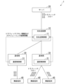
- FIG. 2 is a block diagram showing the overall configuration of the signal transmission system 1 according to the first embodiment of the present invention.
- the signal transmission system 1 includes an optical transmission device 10, a server 20, a plurality of base stations 30, and a plurality of wireless terminals 40. Note that, as an example, two base stations 30 and three wireless terminals 40 are shown in Fig. 2, but the number of base stations 30 and wireless terminals 40 may be any number.
- the optical transmission device 10 is provided on the signal transmission path between the server 20 and the base station 30.
- the optical transmission device 10 is a transfer device that transmits signals between the server 20 and the wireless terminal 40.
- the server 20 is a communication device that transmits multiple traffic flows to and from multiple wireless terminals 40 via the optical transmission device 10 and the base station 30.
- the wireless terminal 40 is a communication device that transmits multiple traffic flows to and from the server 20 via the base station 30 and the optical transmission device 10.
- the base station 30 accommodates multiple wireless terminals 40.
- the base station 30 is a communication device that transmits signals wirelessly to and from the wireless terminals 40, and transmits signals (optical signals) via wires to and from the optical transmission device 10.
- the base station 30 transmits signals received from the wireless terminals 40 to the optical transmission device 10, and transmits signals received from the optical transmission device 10 to the wireless terminals 40.
- the signal transmission system 1 is a mobile communication system in which the wireless terminal 40 and the server 20 transmit multiple traffic flows to each other via the base station 30 and the optical transmission device 10.
- the section between the wireless terminal 40 and the base station 30 is a wireless section in which signals are transmitted wirelessly.
- the section between the base station 30 and the server 20 is a wired section in which signals are transmitted wired.
- each traffic flow is assigned a network class identifier, such as NSSAI, or a QoS class identifier, such as 5QI.
- NSSAI network class identifier
- QoS class identifier such as 5QI.
- the optical transmission device 10 includes an optical transmission control unit 11. Furthermore, each base station 30 includes a communication control unit 31. The communication control unit 31 of the base station 30 transmits traffic flow information and scheduling result information to the optical transmission control unit 11 of the optical transmission device 10.
- the traffic flow information here refers to information about the traffic flow established when the base station 30 and the wireless terminal 40 are connected.
- the traffic flow information is, for example, an ID (identifier) that identifies the wireless terminal 40, an ID that identifies the traffic flow, an identifier that identifies the QoS class, or an identifier that identifies the network slice.
- the scheduling result information here refers to information indicating the results of time and frequency scheduling performed by the base station 30 for each traffic flow in a wireless section for each time section, based on wireless feedback information successively transmitted from the wireless terminal 40.
- the wireless feedback information is, for example, information indicating the remaining buffer capacity for each traffic flow in the wireless terminal 40, or information indicating the quality of the wireless channel.
- the optical transmission control unit 11 of the optical transmission device 10 acquires the traffic flow information and the scheduling result information transmitted from the communication control unit 31 of the base station 30. Based on the acquired traffic flow information and scheduling result information, the optical transmission control unit 11 assigns wavelengths to be used in the wired section (i.e., the wavelengths to be used between the server 20 and the optical transmission device 10, and the wavelengths to be used between the optical transmission device 10 and the base station 30) for each traffic flow, dividing the time intervals, for each base station 30.
- the wavelength allocation may be performed for each wireless terminal 40. Alternatively, the wavelength allocation may be performed for each QoS class identifier of a traffic flow or for each network slice identifier.
- the wavelengths may be allocated for each subcarrier of an optical OFDM (Orthogonal Frequency Division Multiplexing) signal.
- the base station 30 may be provided with, for example, a wavelength-tunable transceiver (not shown), and the wavelength assigned by the optical transmission control unit 11 may be used both between the base station 30 and the optical transmission device 10 and between the optical transmission device 10 and the server 20.
- the wavelength assigned by the optical transmission control unit 11 may be used only between the optical transmission device 10 and the server 20, and signals may be transmitted between the base station 30 and the optical transmission device 10 by time division multiplexing using one wavelength, as in the signal transmission system 6 shown in FIG. 1 described above.
- the optical transmission control unit 11 of the optical transmission device 10 may perform the scheduling in the above-mentioned wireless section. That is, instead of obtaining scheduling result information from the communication control unit 31 of the base station 30, the optical transmission control unit 11 of the optical transmission device 10 may obtain wireless feedback information sequentially transmitted from the wireless terminal 40, information related to the scheduling policy established at the time of connection, and traffic flow information.
- the optical transmission control unit 11 may then perform scheduling based on the acquired wireless feedback information, information on the scheduling policy, and traffic flow information.
- the scheduling policy may be, for example, round robin, proportional fair, or throughput maximization.
- the base station 30 may be, for example, a Wi-Fi (registered trademark) access point.
- the signal transmission system 1 does not necessarily have to be a mobile communication system, and may be a wireless communication system other than a mobile communication system.
- FIG. 3 is a flowchart showing the operation of the signal transmission system 1 in the first embodiment of the present invention.
- the base station 30 acquires information regarding the traffic flow established when connecting with the wireless terminal 40 and wireless feedback information sequentially transmitted from the wireless terminal 40 (step S001).
- the base station 30 performs time and frequency scheduling for each traffic flow in the wireless section for each time interval based on the wireless feedback information (step S002).
- the communication control unit 31 of the base station 30 transmits the traffic flow information and the scheduling result information to the optical transmission control unit 11 of the optical transmission device 10 (step S003).
- the optical transmission control unit 11 of the optical transmission device 10 acquires the traffic flow information and the scheduling result information transmitted from the communication control unit 31 of the base station 30 (step S004).
- the optical transmission control unit 11 of the optical transmission device 10 divides time intervals into time periods and assigns wavelengths to be used in the wired section (i.e., the wavelengths to be used between the server 20 and the optical transmission device 10, and the wavelengths to be used between the optical transmission device 10 and the base station 30) to each traffic flow for each base station 30 based on the acquired traffic flow information and scheduling result information (step S005). This completes the operation of the signal transmission system 1 shown in the flowchart of FIG. 3.
- the base station 30 schedules time and frequency in the wireless section, similar to the conventional signal transmission system 6. Then, the communication control unit 31 of the base station 30 transmits scheduling result information indicating the result of the scheduling (i.e., the result of time and frequency resource allocation for each traffic flow in the wireless section) and traffic flow information indicating the state of traffic flow in the wireless section (e.g., the number of wireless terminals and an identifier for each traffic) to the optical transmission control unit 11 of the optical transmission device 10. Then, based on the acquired traffic flow information and scheduling result information, the optical transmission control unit 11 of the optical transmission device 10 assigns multiple wavelengths to each traffic flow in the wired section.
- scheduling result information indicating the result of the scheduling
- traffic flow information indicating the state of traffic flow in the wireless section (e.g., the number of wireless terminals and an identifier for each traffic)
- the optical transmission control unit 11 of the optical transmission device 10 assigns multiple wavelengths to each traffic flow in the wired section.
- the signal transmission system 1 in the first embodiment can transmit multiple traffic flows in parallel by wavelength division multiplexing even in the wired section between the server 20 and the base station 30. This allows the signal transmission system 1 to suppress the occurrence of delays associated with serialization of signals by time division multiplexing, which occurs in the wired section of the conventional signal transmission system 6.
- the optical transmission device 10 assigns, for each time interval, only wavelengths that correspond to traffic flows to which frequency resources are assigned in the wireless interval. This reduces the number of wavelengths used, improving the efficiency of wavelength usage.
- the signal transmission system 1 in the first embodiment described above was a mobile communication system in which a wireless terminal 40 and a server 20 transmit multiple traffic flows to each other via a base station 30 and an optical transmission device 10.
- the section between the wireless terminal 40 and the base station 30 was a wireless section in which signals were transmitted wirelessly
- the section between the base station 30 and the server 20 was a wired section in which signals were transmitted wired.
- the signal transmission system 1a in the second embodiment described below has a base station consisting of a central station 20a and multiple distributed stations 30a, which will be described later.
- the base station accommodates multiple wireless terminals 40.
- the optical transmission device 10 is provided on the signal transmission path between the central station 20a and the distributed stations 30a.
- the optical transmission device 10a is a transfer device that transmits signals transmitted between the central station 20a and the wireless terminals 40.
- the signal transmission system 1a in the second embodiment is a mobile communication system in which a wireless terminal 40 and a central station 20a transmit multiple traffic flows to each other via a distributed station 30a and an optical transmission device 10.
- the section between the wireless terminal 40 and the distributed station 30a is a wireless section in which signals are transmitted wirelessly
- the section between the distributed station 30a and the central station 20a is a wired section in which signals are transmitted wired.
- the multiple distributed stations 30a and the central station 20a in the second embodiment are multiple DUs (Distributed Units) and CUs (Central Units) in a mobile communication system.
- the section between the CU and DU in which the optical transmission device 10 is installed is called an MMH (Mobile Midhaul).
- the multiple distributed stations 30a and the central station 20a in the second embodiment may be multiple RUs (Radio Units) and DU in a mobile communication system.
- the section between the DU and RU in which the optical transmission device 10 is installed is called an MFH (Mobile Fronthaul).
- the distributed station 30a described below schedules the time and frequency in the wireless section.
- the distributed station 30a transmits a control signal indicating the result of the scheduling (e.g., the result of time and frequency resource allocation) and the state of the traffic flow in the wireless section (e.g., the number of wireless terminals and an identifier for each traffic) to the optical transmission device 10 described below.
- the optical transmission device 10 assigns multiple wavelengths to each traffic flow in the wired section according to the acquired traffic flow state and the scheduling results.
- signals are transmitted by time division multiplexing using one wavelength in the wired section
- signals are transmitted by wavelength division multiplexing using multiple wavelengths in the wired section.
- [Configuration of signal transmission system] 4 is a block diagram showing the overall configuration of a signal transmission system 1a according to a second embodiment of the present invention.
- the configuration of the signal transmission system 1a according to the second embodiment is the same as the configuration of the signal transmission system 1 according to the first embodiment, the description may be omitted.
- the signal transmission system 1a includes an optical transmission device 10, a central station 20a, a plurality of distributed stations 30a, and a plurality of wireless terminals 40.
- FIG. 4 shows two distributed stations 30a and three wireless terminals 40, but the number of distributed stations 30a and wireless terminals 40 may be any number.
- the optical transmission device 10 is provided on the signal transmission path between the central station 20a and the distributed station 30a.
- the optical transmission device 10 is a transfer device that transmits signals between the central station 20a and the wireless terminal 40.
- the central station 20a is a communication device that transmits multiple traffic flows to and from multiple wireless terminals 40 via the optical transmission device 10 and the distributed station 30a.
- the wireless terminals 40 are communication devices that transmit multiple traffic flows to and from the central station 20a via the distributed station 30a and the optical transmission device 10.
- the distributed station 30a is a communication device that transmits signals wirelessly to and from the wireless terminal 40, and transmits signals (optical signals) via wires to and from the optical transmission device 10.
- the distributed station 30a transmits signals received from the wireless terminal 40 to the optical transmission device 10, and transmits signals received from the optical transmission device 10 to the wireless terminal 40.
- the signal transmission system 1a is a mobile communication system in which the wireless terminal 40 and the central station 20a transmit multiple traffic flows to each other via the distributed station 30a and the optical transmission device 10.
- the section between the wireless terminal 40 and the distributed station 30a is a wireless section in which signals are transmitted wirelessly.
- the section between the distributed station 30a and the central station 20a is a wired section in which signals are transmitted wired.
- each traffic flow is assigned a network class identifier, such as NSSAI, or a QoS class identifier, such as 5QI.
- NSSAI network class identifier
- QoS class identifier such as 5QI.
- the optical transmission device 10 includes an optical transmission control unit 11. Furthermore, each distributed station 30a includes a communication control unit 31. The communication control unit 31 of the distributed station 30a transmits traffic flow information and scheduling result information to the optical transmission control unit 11 of the optical transmission device 10.
- the traffic flow information here refers to information about the traffic flow established when the remote station 30a and the wireless terminal 40 are connected.
- the traffic flow information is, for example, an ID that identifies the wireless terminal 40, an ID that identifies the traffic flow, an identifier that identifies the QoS class, or an identifier that identifies the network slice.
- the traffic flow information may be, for example, a slot ID, a symbol ID, a resource block ID, or a MIMO (Multiple Input Multiple Output) layer number, etc.
- the scheduling result information here refers to information indicating the results of time and frequency scheduling performed by the remote station 30a for each traffic flow in a wireless section for each time section, based on wireless feedback information successively transmitted from the wireless terminal 40.
- the wireless feedback information is, for example, information indicating the remaining amount of buffer space for each traffic flow in the wireless terminal 40, or information indicating the quality of the wireless channel.
- the optical transmission control unit 11 of the optical transmission device 10 acquires the traffic flow information and the scheduling result information transmitted from the communication control unit 31 of the distributed station 30a. Based on the acquired traffic flow information and scheduling result information, the optical transmission control unit 11 assigns wavelengths to be used in the wired section (i.e., the wavelengths to be used between the central station 20a and the optical transmission device 10, and the wavelengths to be used between the optical transmission device 10 and the distributed station 30a) for each traffic flow, dividing the time intervals, for each distributed station 30a.
- the wavelengths may be allocated for each wireless terminal 40. Alternatively, the wavelengths may be allocated for each QoS class identifier of the traffic flow, or for each network slice identifier. The wavelengths may be allocated for each subcarrier of the optical OFDM signal. The wavelengths may be allocated for each slot ID, symbol ID, resource block ID, or MIMO layer number.
- the distributed station 30a may be provided with, for example, a wavelength-tunable transceiver (not shown), and the wavelength assigned by the optical transmission control unit 11 may be used both between the distributed station 30a and the optical transmission device 10, and between the optical transmission device 10 and the central station 20a.
- the wavelength assigned by the optical transmission control unit 11 may be used only between the optical transmission device 10 and the central station 20a, and signals may be transmitted between the distributed station 30a and the optical transmission device 10 by time division multiplexing using one wavelength, as in the signal transmission system 6 shown in FIG. 1 described above.
- the optical transmission control unit 11 of the optical transmission device 10 may perform the scheduling in the above-mentioned wireless section. That is, instead of obtaining scheduling result information from the communication control unit 31 of the distributed station 30a, the optical transmission control unit 11 of the optical transmission device 10 may obtain wireless feedback information sequentially transmitted from the wireless terminal 40, information related to the scheduling policy established at the time of connection, and traffic flow information.
- the optical transmission control unit 11 may then perform scheduling based on the acquired wireless feedback information, information on the scheduling policy, and traffic flow information.
- the scheduling policy may be, for example, round robin, proportional fair, or throughput maximization.
- the central station 20a may be, for example, a Wi-Fi (registered trademark) controller, and the remote station 30a may be, for example, a Wi-Fi (registered trademark) access point.
- the signal transmission system 1a does not necessarily have to be a mobile communication system, and may be a wireless communication system other than a mobile communication system.
- the distributed station 30a schedules time and frequency in the wireless section.
- the communication control unit 31 of the distributed station 30a then transmits scheduling result information indicating the result of the scheduling (i.e., the result of time and frequency resource allocation for each traffic flow in the wireless section) and traffic flow information indicating the state of traffic flow in the wireless section (e.g., the number of wireless terminals and an identifier for each traffic) to the optical transmission control unit 11 of the optical transmission device 10.
- the optical transmission control unit 11 of the optical transmission device 10 then assigns multiple wavelengths to each traffic flow in the wired section based on the acquired traffic flow information and scheduling result information.
- the signal transmission system 1a in the second embodiment can transmit multiple traffic flows in parallel by wavelength division multiplexing even in the wired section between the central station 20a and the distributed station 30a. This allows the signal transmission system 1a to suppress the occurrence of delays associated with serialization of signals by time division multiplexing, which occurs in the wired section of the conventional signal transmission system 6.
- the optical transmission device 10 assigns, for each time interval, only wavelengths that correspond to traffic flows to which frequency resources are assigned in the wireless interval. This reduces the number of wavelengths used, improving the efficiency of wavelength usage.
- the distributed station 30a is configured to schedule time and frequency in the wireless section.
- the communication control unit 31 of the distributed station 30a is configured to transmit a control signal indicating the result of the scheduling (e.g., the result of time and frequency resource allocation) and the state of the traffic flow in the wireless section (e.g., the number of wireless terminals and an identifier for each traffic) to the optical transmission control unit 11 of the optical transmission device 10.
- a communication control unit 21 is provided in a central station 20b described below instead of a distributed station 30b described below.
- the central station 20b schedules time and frequency in the wireless section.
- the communication control unit 21 of the central station 20b then transmits a control signal indicating the results of the scheduling (e.g., the results of time and frequency resource allocation) and the state of traffic flow in the wireless section (e.g., the number of wireless terminals and an identifier for each traffic) to the optical transmission control unit 11 of the optical transmission device 10.
- the optical transmission device 10 assigns multiple wavelengths to each traffic flow in the wired section according to the acquired traffic flow state and the scheduling result.
- signals are transmitted by time division multiplexing using one wavelength in the wired section
- signals are transmitted by wavelength division multiplexing using multiple wavelengths in the wired section.
- [Configuration of signal transmission system] 5 is a block diagram showing the overall configuration of a signal transmission system 1b according to a third embodiment of the present invention.
- the configuration of the signal transmission system 1b according to the third embodiment is the same as the configuration of the signal transmission system 1a according to the second embodiment, the description may be omitted.
- the signal transmission system 1b includes an optical transmission device 10, a central station 20b, a plurality of distributed stations 30b, and a plurality of wireless terminals 40. Note that, as an example, FIG. 5 shows two distributed stations 30b and three wireless terminals 40, but the number of distributed stations 30b and wireless terminals 40 may be any number.
- the optical transmission device 10 is provided on the signal transmission path between the central station 20b and the distributed station 30b.
- the optical transmission device 10 is a transfer device that transmits signals between the central station 20a and the wireless terminal 40.
- the central station 20b is a communication device that transmits multiple traffic flows to and from multiple wireless terminals 40 via the optical transmission device 10 and the distributed station 30b.
- the wireless terminal 40 is a communication device that transmits multiple traffic flows to and from the central station 20b via the distributed station 30b and the optical transmission device 10.
- the distributed station 30b is a communication device that transmits signals wirelessly to and from the wireless terminal 40, and transmits signals (optical signals) via wires to and from the optical transmission device 10.
- the distributed station 30b transmits signals received from the wireless terminal 40 to the optical transmission device 10, and transmits signals received from the optical transmission device 10 to the wireless terminal 40.
- the signal transmission system 1b is a mobile communication system in which the wireless terminal 40 and the central station 20b transmit multiple traffic flows to each other via the distributed station 30b and the optical transmission device 10.
- the section between the wireless terminal 40 and the distributed station 30b is a wireless section in which signals are transmitted wirelessly.
- the section between the distributed station 30b and the central station 20b is a wired section in which signals are transmitted wired.
- each traffic flow is assigned a network class identifier, such as NSSAI, or a QoS class identifier, such as 5QI.
- NSSAI network class identifier
- QoS class identifier such as 5QI.
- the optical transmission device 10 includes an optical transmission control unit 11.
- the central station 20b includes a communication control unit 21.
- the communication control unit 21 of the central station 20b transmits traffic flow information and scheduling result information to the optical transmission control unit 11 of the optical transmission device 10.
- the traffic flow information may be, for example, a slot ID, a symbol ID, a resource block ID, or a MIMO layer number.
- the scheduling result information here refers to information indicating the results of time and frequency scheduling performed by the central station 20b for each traffic flow in a wireless section for each time section, based on wireless feedback information successively transmitted from the wireless terminal 40.
- the wireless feedback information is, for example, information indicating the remaining buffer capacity for each traffic flow in the wireless terminal 40, or information indicating the quality of the wireless channel.
- the optical transmission control unit 11 of the optical transmission device 10 acquires the traffic flow information and the scheduling result information transmitted from the communication control unit 21 of the central station 20b. Based on the acquired traffic flow information and scheduling result information, the optical transmission control unit 11 assigns wavelengths to be used in the wired section (i.e., the wavelengths to be used between the central station 20b and the optical transmission device 10, and the wavelengths to be used between the optical transmission device 10 and the distributed station 30b) for each traffic flow, dividing the time intervals, for each distributed station 30b.
- the above wavelength allocation may be performed for each wireless terminal 40. Alternatively, the above wavelength allocation may be performed for each QoS class identifier of the traffic flow, or for each network slice identifier. The above wavelength allocation may be performed for each subcarrier of the optical OFDM signal.
- the distributed station 30b may be equipped with, for example, a wavelength-tunable transceiver (not shown), and the wavelength assigned by the optical transmission control unit 11 may be used both between the distributed station 30b and the optical transmission device 10, and between the optical transmission device 10 and the central station 20b.
- the wavelength assigned by the optical transmission control unit 11 may be used only between the optical transmission device 10 and the central station 20b, and signals may be transmitted between the distributed station 30b and the optical transmission device 10 by time division multiplexing using one wavelength, as in the signal transmission system 6 shown in FIG. 1 described above.
- the central station 20b may be, for example, a Wi-Fi (registered trademark) controller, and the remote station 30b may be, for example, a Wi-Fi (registered trademark) access point.
- the signal transmission system 1b does not necessarily have to be a mobile communication system, and may be a wireless communication system other than a mobile communication system.
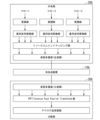
- FIG. 6 is a schematic diagram showing an example of a configuration for downlink signal transmission by a signal transmission system in the prior art.
- an optical transmission device 60a, a central station 70a, and a distributed station 80a are shown from the conventional signal transmission system.
- the central station 70a is configured to include a modulation section and a serial-to-parallel conversion section for each traffic flow, a resource element mapping section, and a parallel-to-serial conversion section. Note that FIG. 6 only shows three traffic flows, flows 1 to 3.
- the resource element mapping unit of the central station 70a assigns time and frequency resources to each traffic flow output from each serial-to-parallel conversion unit.
- the parallel-to-serial conversion unit of the central station 70a converts multiple traffic flows transmitted in parallel into serial and transmits the signal in serial by time division multiplexing.
- the distributed station 80a is configured to include a serial-to-parallel conversion section, an IFFT (Inverse Fast Fourier Transform) section, and an analog transmission/reception section.
- IFFT Inverse Fast Fourier Transform
- the serial-to-parallel conversion unit of the distributed station 80a receives the time-division multiplexed signal and converts the multiple traffic flows transmitted serially into parallel traffic flows.
- the IFFT (Inverse Fast Fourier Transform) unit of the distributed station 80a performs modulation by performing an inverse fast Fourier transform on the converted signal.
- FIG. 7 is a schematic diagram showing an example of the configuration of downlink signal transmission by the signal transmission system 1b in the third embodiment.
- the optical transmission device 10b, the central station 20b, and the distributed station 30b are shown as excerpts from the signal transmission system 1b.
- the central station 20b is configured to include a modulation section and a serial-to-parallel conversion section for each traffic flow, a resource element mapping section, and a wavelength multiplexing section (multiplexing section). Note that FIG. 7 only shows three traffic flows, flows 1 to 3.
- the resource element mapping unit of the central station 20b assigns time and frequency resources to each traffic flow output from each serial-to-parallel conversion unit.
- the wavelength multiplexing unit (multiplexing unit) of the central station 20b assigns wavelengths to each of the multiple traffic flows transmitted in parallel, multiplexes them, and transmits signals in parallel using wavelength division multiplexing.
- the distributed station 30b includes a wavelength multiplexing section (demultiplexing section), an IFFT section, and an analog transmission/reception section.
- the serial-to-parallel conversion section of the distributed station 80a receives and splits the signals in which multiple traffic flows have been wavelength-division multiplexed and transmitted in parallel.
- the IFFT (Inverse Fast Fourier Transform) section of the distributed station 80a performs modulation by performing an inverse fast Fourier transform on the split signals.
- the serial-parallel conversion units provided in the central station 70a and the distributed station 80a of the signal transmission system in the prior art are replaced with a wavelength multiplexing unit (multiplexing unit) and a wavelength multiplexing unit (demultiplexing unit) in the signal transmission system 1b in the third embodiment, respectively.
- the signal transmission system 1b in the third embodiment can transmit multiple traffic flows in parallel by wavelength division multiplexing even in the wired section between the central station 20b and the distributed station 30b.
- the central station 20b schedules time and frequency in the wireless section.
- the communication control unit 21 of the central station 20b then transmits scheduling result information indicating the result of the scheduling (i.e., the result of time and frequency resource allocation for each traffic flow in the wireless section) and traffic flow information indicating the state of traffic flow in the wireless section (e.g., the number of wireless terminals and an identifier for each traffic) to the optical transmission control unit 11 of the optical transmission device 10.
- the optical transmission control unit 11 of the optical transmission device 10 then assigns multiple wavelengths to each traffic flow in the wired section based on the acquired traffic flow information and scheduling result information.
- the signal transmission system 1b in the third embodiment can transmit multiple traffic flows in parallel by wavelength division multiplexing even in the wired section between the central station 20b and the distributed station 30b. This allows the signal transmission system 1b to suppress the occurrence of delays associated with serialization of signals by time division multiplexing, which occurs in the wired section of the conventional signal transmission system 6.
- the optical transmission device 10 assigns only wavelengths corresponding to traffic flows to which frequency resources are assigned in the wireless section for each time section. This reduces the number of wavelengths used, improving the efficiency of wavelength usage.
- the traffic flow information and scheduling result information are transmitted directly from the communication control unit 31 of the base station 30 to the optical transmission control unit 11 of the optical transmission device 10.
- the signal transmission system 1c in the fourth embodiment described below further includes a wireless controller 50 that controls the base station 30c described below, and an optical transmission device controller 55 that controls the optical transmission device 10c described below.
- the wireless controller 50 collects traffic flow information and scheduling result information from each of the communication control units 31 of the multiple base stations 30c, and transmits them to the optical transmission device controller 55.
- the optical transmission device controller 55 then assigns wavelengths to be used in the wired section to each traffic flow based on the traffic flow information and the scheduling result information.
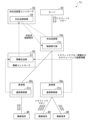
- FIG. 8 is a block diagram showing the overall configuration of a signal transmission system 1c according to a fourth embodiment of the present invention.
- the signal transmission system 1c includes an optical transmission device 10c, a server 20, a plurality of base stations 30c, a plurality of wireless terminals 40, a wireless controller 50, and an optical transmission device controller 55.
- the signal transmission system 1c includes an optical transmission device 10c, a server 20, a plurality of base stations 30c, a plurality of wireless terminals 40, a wireless controller 50, and an optical transmission device controller 55.
- the signal transmission system 1c includes an optical transmission device 10c, a server 20, a plurality of base stations 30c, a plurality of wireless terminals 40, a wireless controller 50, and an optical transmission device controller 55.
- two base stations 30c and three wireless terminals 40 are illustrated, but the number of base stations 30c and wireless terminals 40 may be any number.
- the optical transmission device 10c is provided on the signal transmission path between the server 20 and the base station 30c.
- the optical transmission device 10c is a transfer device that transmits signals between the server 20 and the wireless terminal 40.
- the server 20 is a communication device that transmits multiple traffic flows to and from multiple wireless terminals 40 via the optical transmission device 10 and base station 30c.
- the wireless terminal 40 is a communication device that transmits multiple traffic flows to and from the server 20 via the base station 30c and the optical transmission device 10c.
- the base station 30c accommodates multiple wireless terminals 40.
- the base station 30c is a communication device that transmits signals wirelessly to and from the wireless terminals 40, and transmits signals (optical signals) via wires to and from the optical transmission device 10c.
- the base station 30c transmits signals received from the wireless terminals 40 to the optical transmission device 10c, and transmits signals received from the optical transmission device 10c to the wireless terminals 40.
- the signal transmission system 1c is a mobile communication system in which the wireless terminal 40 and the server 20 transmit multiple traffic flows to each other via the base station 30c and the optical transmission device 10c.
- the section between the wireless terminal 40 and the base station 30c is a wireless section in which signals are transmitted wirelessly.
- the section between the base station 30c and the server 20 is a wired section in which signals are transmitted wired.
- each traffic flow is assigned a network class identifier, such as NSSAI, or a QoS class identifier, such as 5QI.
- NSSAI network class identifier
- QoS class identifier such as 5QI.
- the optical transmission device 10c includes a control execution unit 11c. Furthermore, each base station 30c includes a communication control unit 31c. Furthermore, the wireless controller 50 includes an information transmission unit 51. Furthermore, the optical transmission device controller 55 includes an optical transmission control unit 56.
- the communication control unit 31c of the base station 30c transmits the traffic flow information and the scheduling result information to the information transmission unit 51 of the wireless controller 50.
- the traffic flow information here refers to information about the traffic flow established when the base station 30c and the wireless terminal 40 are connected.
- the traffic flow information is, for example, an ID that identifies the wireless terminal 40, an ID that identifies the traffic flow, an identifier that identifies the QoS class, or an identifier that identifies the network slice.
- the scheduling result information here refers to information indicating the results of time and frequency scheduling performed by the base station 30c for each traffic flow in a wireless section for each time section, based on wireless feedback information successively transmitted from the wireless terminal 40.
- the wireless feedback information is, for example, information indicating the remaining amount of buffer space for each traffic flow in the wireless terminal 40, or information indicating the quality of the wireless channel.
- the information transmission unit 51 of the wireless controller 50 acquires the traffic flow information and the scheduling result information sent from the communication control unit 31c of the base station 30c.
- the information transmission unit 51 transmits the traffic flow information and the scheduling result information collected from each of the base stations 30c to the optical transmission control unit 56 of the optical transmission device controller 55.
- the optical transmission control unit 56 of the optical transmission device controller 55 acquires the traffic flow information and the scheduling result information transmitted from the information transmission unit 51 of the wireless controller 50. Based on the acquired traffic flow information and scheduling result information, the optical transmission control unit 56 assigns wavelengths to be used in the wired section (i.e., the wavelengths to be used between the server 20 and the optical transmission device 10c, and the wavelengths to be used between the optical transmission device 10c and the base station 30c) for each traffic flow, dividing the time intervals, for each base station 30c.
- the optical transmission control unit 56 transmits an optical transmission control instruction including information indicating the result of the wavelength allocation to the control execution unit 11c of the optical transmission device 10c.
- the control execution unit 11c of the optical transmission device 10c controls the wavelength for each traffic flow according to the result of the wavelength allocation based on the acquired optical transmission control instruction.
- the above wavelength allocation may be performed for each wireless terminal 40. Alternatively, the above wavelength allocation may be performed for each QoS class identifier of the traffic flow, or for each network slice identifier. The above wavelength allocation may be performed for each subcarrier of the optical OFDM signal.
- the base station 30c may be provided with, for example, a wavelength-tunable transceiver (not shown), and the wavelength assigned by the optical transmission control unit 56 may be used both between the base station 30c and the optical transmission device 10c and between the optical transmission device 10c and the server 20.
- the wavelength assigned by the optical transmission control unit 56 may be used only between the optical transmission device 10c and the server 20, and signals may be transmitted between the base station 30c and the optical transmission device 10c by time division multiplexing using one wavelength, as in the signal transmission system 6 shown in FIG. 1 described above.
- control execution unit 11c of the optical transmission device 10c may perform the scheduling in the above-mentioned wireless section. That is, instead of obtaining the scheduling result information from the optical transmission control unit 56 of the optical transmission device controller 55, the control execution unit 11c of the optical transmission device 10c may obtain the wireless feedback information sequentially transmitted from the wireless terminal 40, the information related to the scheduling policy established at the time of connection, and the traffic flow information via the wireless controller 50 and the optical transmission device controller 55.
- control execution unit 11c may perform scheduling based on the acquired wireless feedback information, information on the scheduling policy, and traffic flow information.
- the scheduling policy referred to here may be, for example, round robin, proportional fair, and throughput maximization.
- the wireless controller 50 and the optical transmission device controller 55 may obtain connection information between the server 20 and the wireless terminal 40, such as a network slice or QoS, from a higher-level controller (not shown), such as an orchestrator.
- the base station 30c may be, for example, a Wi-Fi (registered trademark) access point.
- the signal transmission system 1c does not necessarily have to be a mobile communication system, and may be a wireless communication system other than a mobile communication system.
- the base station 30c schedules the time and frequency in the wireless section, as in the conventional signal transmission system 6.
- the communication control unit 31c of the base station 30c then transmits to the information transmission unit 51 of the wireless controller 50 scheduling result information indicating the result of the scheduling (i.e., the result of the resource allocation of time and frequency for each traffic flow in the wireless section) and traffic flow information indicating the state of the traffic flow in the wireless section (e.g., the number of wireless terminals and an identifier for each traffic).
- the information transmission unit 51 of the wireless controller 50 transmits the traffic flow information and scheduling result information collected from each of the base stations 30c to the optical transmission control unit 56 of the optical transmission device controller 55.
- the optical transmission control unit 56 of the optical transmission device controller 55 then allocates multiple wavelengths for each traffic flow in the wired section based on the acquired traffic flow information and scheduling result information.
- the signal transmission system 1c in the fourth embodiment can transmit multiple traffic flows in parallel by wavelength division multiplexing even in the wired section between the server 20 and the base station 30c. This allows the signal transmission system 1c to suppress the occurrence of delays associated with serialization of signals by time division multiplexing, which occurs in the wired section of the conventional signal transmission system 6.
- the optical transmission device controller 55 assigns only wavelengths corresponding to traffic flows to which frequency resources are assigned in the wireless section for each time section. This reduces the number of wavelengths used, improving the efficiency of wavelength usage.
- the signal transmission system 1c in the fourth embodiment described above was a mobile communication system in which a wireless terminal 40 and a server 20 transmit multiple traffic flows to each other via a base station 30c and an optical transmission device 10c.
- the section between the wireless terminal 40 and the base station 30c was a wireless section in which signals were transmitted wirelessly
- the section between the base station 30c and the server 20 was a wired section in which signals were transmitted wired.
- the signal transmission system 1d in the fifth embodiment described below has a base station consisting of a central station 20d and multiple distributed stations 30d.
- the base station accommodates multiple wireless terminals 40.
- the optical transmission device 10d is provided on the signal transmission path between the central station 20d and the distributed stations 30d.
- the optical transmission device 10d is a transfer device that transmits signals transmitted between the central station 20d and the wireless terminals 40.
- the signal transmission system 1d in the fifth embodiment is a mobile communication system in which a wireless terminal 40 and a central station 20d transmit multiple traffic flows to each other via a distributed station 30d and an optical transmission device 10d.
- the section between the wireless terminal 40 and the distributed station 30d is a wireless section in which signals are transmitted wirelessly
- the section between the distributed station 30d and the central station 20d is a wired section in which signals are transmitted wired.
- the multiple distributed stations 30d and the central station 20d in the fifth embodiment are multiple DUs and CUs in a mobile communication system.
- the section between the CU and DU in which the optical transmission device 10d is installed is an MMH (Mobile Midhaul).
- the multiple distributed stations 30d and the central station 20d in the fifth embodiment may be multiple RUs and DUs in a mobile communication system.
- the section between the DU and RU in which the optical transmission device 10d is installed is an MFH (Mobile Fronthaul).
- the distributed station 30d described below schedules the time and frequency in the wireless section.
- the distributed station 30d then transmits a control signal indicating the result of the scheduling (e.g., the result of the resource allocation of time and frequency) and the state of the traffic flow in the wireless section (e.g., the number of wireless terminals and an identifier for each traffic) to the optical transmission device controller 55 via the wireless controller 50 described below.
- the optical transmission device controller 55 assigns multiple wavelengths to each traffic flow in the wired section according to the acquired traffic flow state and the scheduling result.
- signals are transmitted by time division multiplexing using one wavelength in the wired section
- signals are transmitted by wavelength division multiplexing using multiple wavelengths in the wired section.
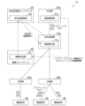
- [Configuration of signal transmission system] 9 is a block diagram showing the overall configuration of a signal transmission system 1d according to a fifth embodiment of the present invention.
- the configuration of the signal transmission system 1d according to the fifth embodiment is the same as the configuration of the signal transmission system 1c according to the fourth embodiment, the description may be omitted.
- the signal transmission system 1d includes an optical transmission device 10d, a central station 20d, a plurality of distributed stations 30d, a plurality of wireless terminals 40, a wireless controller 50, and an optical transmission device controller 55.
- FIG. 9 shows two distributed stations 30d and three wireless terminals 40, but the number of distributed stations 30d and wireless terminals 40 may be any number.
- the optical transmission device 10d is provided on the signal transmission path between the central station 20d and the distributed station 30d.
- the optical transmission device 10d is a transfer device that transmits signals between the central station 20d and the wireless terminal 40.
- the central station 20d is a communication device that transmits multiple traffic flows to and from multiple wireless terminals 40 via the optical transmission device 10d and the distributed station 30d.
- the wireless terminal 40 is a communication device that transmits multiple traffic flows to and from the central station 20d via the distributed station 30d and the optical transmission device 10d.
- the distributed station 30d is a communication device that transmits signals wirelessly to and from the wireless terminal 40, and transmits signals (optical signals) via wires to and from the optical transmission device 10d.
- the distributed station 30d transmits signals received from the wireless terminal 40 to the optical transmission device 10d, and transmits signals received from the optical transmission device 10d to the wireless terminal 40.
- the signal transmission system 1d is a mobile communication system in which the wireless terminal 40 and the central station 20d transmit multiple traffic flows to each other via the remote station 30d and the optical transmission device 10d.
- the section between the wireless terminal 40 and the remote station 30d is a wireless section in which signals are transmitted wirelessly.
- the section between the remote station 30d and the central station 20d is a wired section in which signals are transmitted wired.
- each traffic flow is assigned a network class identifier, such as NSSAI, or a QoS class identifier, such as 5QI.
- NSSAI network class identifier
- QoS class identifier such as 5QI.
- the optical transmission device 10d includes a control execution unit 11d. Furthermore, each of the distributed stations 30d includes a communication control unit 31d. Furthermore, the wireless controller 50 includes an information transmission unit 51. Furthermore, the optical transmission device controller 55 includes an optical transmission control unit 56.
- the communication control unit 31d of the remote station 30d transmits the traffic flow information and the scheduling result information to the information transmission unit 51 of the wireless controller 50.
- the traffic flow information here refers to information about the traffic flow established when the remote station 30d and the wireless terminal 40 are connected.
- the traffic flow information is, for example, an ID that identifies the wireless terminal 40, an ID that identifies the traffic flow, an identifier that identifies the QoS class, or an identifier that identifies the network slice.
- the traffic flow information may be, for example, a slot ID, a symbol ID, a resource block ID, or a MIMO layer number.
- the scheduling result information here refers to information indicating the results of time and frequency scheduling performed by the remote station 30d for each traffic flow in a wireless section for each time section, based on wireless feedback information successively transmitted from the wireless terminal 40.
- the wireless feedback information is, for example, information indicating the remaining amount of buffer space for each traffic flow in the wireless terminal 40, or information indicating the quality of the wireless channel.
- the information transmission unit 51 of the wireless controller 50 acquires the traffic flow information and the scheduling result information sent from the communication control unit 31d of the remote station 30d.
- the information transmission unit 51 transmits the traffic flow information and the scheduling result information collected from each of the remote stations 30d to the optical transmission control unit 56 of the optical transmission device controller 55.
- the optical transmission control unit 56 of the optical transmission device controller 55 acquires the traffic flow information and the scheduling result information transmitted from the information transmission unit 51 of the wireless controller 50. Based on the acquired traffic flow information and the scheduling result information, the optical transmission control unit 56 assigns wavelengths to be used in the wired section (i.e., the wavelengths to be used between the central station 20d and the optical transmission device 10d, and the wavelengths to be used between the optical transmission device 10d and the remote station 30d) for each traffic flow, dividing the time intervals, for each remote station 30d.
- wavelengths to be used in the wired section i.e., the wavelengths to be used between the central station 20d and the optical transmission device 10d, and the wavelengths to be used between the optical transmission device 10d and the remote station 30d
- the optical transmission control unit 56 transmits an optical transmission control instruction including information indicating the result of the wavelength allocation to the control execution unit 11d of the optical transmission device 10d.
- the control execution unit 11d of the optical transmission device 10d controls the wavelength for each traffic flow according to the result of the wavelength allocation based on the acquired optical transmission control instruction.
- the above wavelength allocation may be performed for each wireless terminal 40. Alternatively, the above wavelength allocation may be performed for each QoS class identifier of the traffic flow, or for each network slice identifier. The above wavelength allocation may be performed for each subcarrier of the optical OFDM signal.
- the distributed station 30d may be equipped with, for example, a wavelength-tunable transceiver (not shown), and the wavelength assigned by the optical transmission control unit 56 may be used both between the distributed station 30d and the optical transmission device 10d and between the optical transmission device 10d and the central station 20d.
- the wavelength assigned by the optical transmission control unit 56 may be used only between the optical transmission device 10d and the central station 20d, and signals may be transmitted between the distributed station 30d and the optical transmission device 10d by time division multiplexing using one wavelength, as in the signal transmission system 6 shown in FIG. 1 described above.
- control execution unit 11d of the optical transmission device 10 may perform the scheduling in the above-mentioned wireless section. That is, instead of obtaining scheduling result information from the optical transmission control unit 56 of the optical transmission device controller 55, the control execution unit 11d of the optical transmission device 10d may obtain wireless feedback information sequentially transmitted from the wireless terminal 40, information related to the scheduling policy established at the time of connection, and traffic flow information.
- control execution unit 11d may perform scheduling based on the acquired wireless feedback information, information on the scheduling policy, and traffic flow information.
- the scheduling policy referred to here may be, for example, round robin, proportional fair, and throughput maximization.
- the wireless controller 50 and the optical transmission device controller 55 may obtain connection information between the central station 20d and the wireless terminal 40, such as a network slice or QoS, from a higher-level controller (not shown), such as an orchestrator.
- the central station 20d may be, for example, a Wi-Fi (registered trademark) controller, and the remote station 30d may be, for example, a Wi-Fi (registered trademark) access point.
- the signal transmission system 1d does not necessarily have to be a mobile communication system, and may be a wireless communication system other than a mobile communication system.
- the distributed station 30d schedules the time and frequency in the wireless section.
- the communication control unit 31d of the distributed station 30d then transmits to the information transmission unit 51 of the wireless controller 50 scheduling result information indicating the result of the scheduling (i.e., the result of the allocation of time and frequency resources for each traffic flow in the wireless section) and traffic flow information indicating the state of the traffic flow in the wireless section (e.g., the number of wireless terminals and an identifier for each traffic).
- the information transmission unit 51 of the wireless controller 50 transmits the traffic flow information and scheduling result information collected from each of the distributed stations 30d to the optical transmission control unit 56 of the optical transmission device controller 55.
- the optical transmission control unit 56 of the optical transmission device controller 55 then allocates multiple wavelengths for each traffic flow in the wired section based on the acquired traffic flow information and scheduling result information.
- the signal transmission system 1d in the fifth embodiment can transmit multiple traffic flows in parallel by wavelength division multiplexing even in the wired section between the central station 20d and the remote station 30d. This allows the signal transmission system 1a to suppress the occurrence of delays associated with serialization of signals by time division multiplexing, which occurs in the wired section of the conventional signal transmission system 6.
- the optical transmission device controller 55 assigns only wavelengths corresponding to traffic flows to which frequency resources are assigned in the wireless section for each time section. This reduces the number of wavelengths used, improving the efficiency of wavelength usage.
- the distributed station 30d is configured to schedule the time and frequency in the wireless section.
- the communication control unit 31 of the distributed station 30d is configured to transmit a control signal indicating the result of the scheduling (e.g., the result of resource allocation of time and frequency) and the state of the traffic flow in the wireless section (e.g., the number of wireless terminals and an identifier for each traffic) to the optical transmission control unit 56 of the optical transmission device controller 55 via the information transmission unit 51 of the wireless controller 50.
- a communication control unit 21e is provided in a central station 20e described below instead of a remote station 30e described below.
- the central station 20e schedules the time and frequency in the wireless section.
- the communication control unit 21 of the central station 20e then transmits a control signal indicating the result of the scheduling (e.g., the result of resource allocation of time and frequency) and the state of the traffic flow in the wireless section (e.g., the number of wireless terminals and an identifier for each traffic) to the optical transmission device controller 55 via a wireless controller 50 described below.
- the optical transmission device controller 55 assigns multiple wavelengths to each traffic flow in the wired section according to the acquired traffic flow state and the scheduling result.
- signals are transmitted by time division multiplexing using one wavelength in the wired section
- signals are transmitted by wavelength division multiplexing using multiple wavelengths in the wired section.
- [Configuration of signal transmission system] 10 is a block diagram showing the overall configuration of a signal transmission system 1e according to a sixth embodiment of the present invention.
- the configuration of the signal transmission system 1e according to the sixth embodiment is the same as the configuration of the signal transmission system 1d according to the fifth embodiment, the description may be omitted.
- the signal transmission system 1e includes an optical transmission device 10e, a central station 20e, a plurality of distributed stations 30e, a plurality of wireless terminals 40, a wireless controller 50, and an optical transmission device controller 55.
- FIG. 10 shows two distributed stations 30e and three wireless terminals 40, but the number of distributed stations 30e and wireless terminals 40 may be any number.
- the optical transmission device 10e is provided on the signal transmission path between the central station 20e and the distributed station 30e.
- the optical transmission device 10e is a transfer device that transmits signals between the central station 20e and the wireless terminal 40.
- the central station 20e is a communication device that transmits multiple traffic flows to and from multiple wireless terminals 40 via the optical transmission device 10e and the distributed station 30e.
- the wireless terminal 40 is a communication device that transmits multiple traffic flows to and from the central station 20e via the distributed station 30e and the optical transmission device 10e.
- the distributed station 30e is a communication device that transmits signals wirelessly to and from the wireless terminal 40, and transmits signals (optical signals) via wires to and from the optical transmission device 10e.
- the distributed station 30e transmits signals received from the wireless terminal 40 to the optical transmission device 10e, and transmits signals received from the optical transmission device 10e to the wireless terminal 40.
- the signal transmission system 1e is a mobile communication system in which the wireless terminal 40 and the central station 20e transmit multiple traffic flows to each other via the distributed station 30e and the optical transmission device 10e.
- the section between the wireless terminal 40 and the distributed station 30e is a wireless section in which signals are transmitted wirelessly.
- the section between the distributed station 30e and the central station 20e is a wired section in which signals are transmitted wired.
- each traffic flow is assigned a network class identifier, such as NSSAI, or a QoS class identifier, such as 5QI.
- NSSAI network class identifier
- QoS class identifier such as 5QI.
- the optical transmission device 10e includes a control execution unit 11e.
- the central station 20e includes a communication control unit 21e.
- the wireless controller 50 includes an information transmission unit 51.
- the optical transmission device controller 55 includes an optical transmission control unit 56.
- the communication control unit 21e of the central station 20e transmits the traffic flow information and the scheduling result information to the information transmission unit 51 of the wireless controller 50.
- the traffic flow information here refers to information about the traffic flow established when the remote station 30e and the wireless terminal 40 are connected.
- the traffic flow information is, for example, an ID that identifies the wireless terminal 40, an ID that identifies the traffic flow, an identifier that identifies the QoS class, or an identifier that identifies the network slice.
- the traffic flow information may be, for example, a slot ID, a symbol ID, a resource block ID, or a MIMO layer number.
- the scheduling result information here refers to information indicating the results of time and frequency scheduling performed by the central station 20e for each traffic flow in a wireless section for each time section, based on wireless feedback information successively transmitted from the wireless terminal 40.
- the wireless feedback information is, for example, information indicating the remaining buffer capacity for each traffic flow in the wireless terminal 40, or information indicating the quality of the wireless channel.
- the information transmission unit 51 of the wireless controller 50 acquires the traffic flow information and the scheduling result information transmitted from the communication control unit 21e of the central station 20e.
- the information transmission unit 51 transmits the traffic flow information and the scheduling result information acquired from the central station 20e to the optical transmission control unit 56 of the optical transmission device controller 55.
- the optical transmission control unit 56 of the optical transmission device controller 55 acquires the traffic flow information and the scheduling result information transmitted from the information transmission unit 51 of the wireless controller 50. Based on the acquired traffic flow information and scheduling result information, the optical transmission control unit 56 assigns wavelengths to be used in the wired section (i.e., the wavelengths to be used between the central station 20e and the optical transmission device 10e, and the wavelengths to be used between the optical transmission device 10e and the remote station 30e) for each traffic flow, dividing the time intervals, for each remote station 30e.
- wavelengths to be used in the wired section i.e., the wavelengths to be used between the central station 20e and the optical transmission device 10e, and the wavelengths to be used between the optical transmission device 10e and the remote station 30e
- the optical transmission control unit 56 transmits an optical transmission control instruction including information indicating the result of the wavelength allocation to the control execution unit 11e of the optical transmission device 10e.
- the control execution unit 11e of the optical transmission device 10e controls the wavelength for each traffic flow according to the result of the wavelength allocation based on the acquired optical transmission control instruction.
- the above wavelength allocation may be performed for each wireless terminal 40. Alternatively, the above wavelength allocation may be performed for each QoS class identifier of the traffic flow, or for each network slice identifier. The above wavelength allocation may be performed for each subcarrier of the optical OFDM signal.
- the distributed station 30e may be provided with, for example, a wavelength-tunable transceiver (not shown), and the wavelength assigned by the optical transmission control unit 56 may be used both between the distributed station 30e and the optical transmission device 10e and between the optical transmission device 10e and the central station 20e.
- the wavelength assigned by the optical transmission control unit 56 may be used only between the optical transmission device 10e and the central station 20e, and signals may be transmitted between the distributed station 30e and the optical transmission device 10e by time division multiplexing using one wavelength, as in the signal transmission system 6 shown in FIG. 1 described above.
- the central station 20e may be, for example, a Wi-Fi (registered trademark) controller, and the remote station 30e may be, for example, a Wi-Fi (registered trademark) access point.
- the signal transmission system 1b does not necessarily have to be a mobile communication system, and may be a wireless communication system other than a mobile communication system.
- the central station 20e schedules the time and frequency in the wireless section.
- the communication control unit 21e of the central station 20e then transmits to the information transmission unit 51 of the wireless controller 50 scheduling result information indicating the result of the scheduling (i.e., the result of the allocation of time and frequency resources for each traffic flow in the wireless section) and traffic flow information indicating the state of the traffic flow in the wireless section (e.g., the number of wireless terminals and an identifier for each traffic).
- the information transmission unit 51 of the wireless controller 50 transmits the traffic flow information and scheduling result information acquired from the central station 20e to the optical transmission control unit 56 of the optical transmission equipment controller 55.
- the optical transmission control unit 56 of the optical transmission equipment controller 55 then assigns multiple wavelengths to each traffic flow for the wired section based on the acquired traffic flow information and scheduling result information.
- the signal transmission system 1e in the sixth embodiment can transmit multiple traffic flows in parallel by wavelength division multiplexing even in the wired section between the central station 20e and the distributed station 30e. This allows the signal transmission system 1e to suppress the occurrence of delays associated with serialization of signals by time division multiplexing, which occurs in the wired section of the conventional signal transmission system 6.
- the optical transmission device controller 55 assigns only wavelengths corresponding to traffic flows to which frequency resources are assigned in the wireless section for each time section. This reduces the number of wavelengths used, improving the efficiency of wavelength usage.
- the signal transmission system has one or more first communication devices that accommodate one or more wireless terminals that transmit multiple traffic flows, and an optical transmission device that transmits signals transmitted between the first communication device and the second communication device.
- the signal transmission system is the signal transmission system 1, 1a-1b in the embodiment
- the wireless terminal is the wireless terminal 40 in the embodiment
- the first communication device is the base station 30 and the distributed stations 30a and 30b in the embodiment
- the second communication device is the server 20 and the central stations 20a and 20b in the embodiment
- the optical transmission device is the optical transmission device 10 and 10b in the embodiment.
- the first communication device includes a communication control unit.
- the communication control unit is the communication control unit 31 or 21 in the embodiment.
- the communication control unit schedules time and frequency for each traffic flow, and transmits to the optical transmission device scheduling result information indicating the scheduling result and traffic flow information indicating the state of the traffic flow in the wireless section.
- the optical transmission device includes an optical transmission control unit.
- the optical transmission control unit is the optical transmission control unit 11 or 11b in the embodiment.
- the optical transmission control unit assigns wavelengths in the wired section to each traffic flow for each time section based on the scheduling result information and traffic flow information transmitted from the communication control unit.
- the signal transmission system includes one or more first communication devices that accommodate one or more wireless terminals that transmit multiple traffic flows, an optical transmission device that transmits signals transmitted between the first communication device and the second communication device, and a controller that controls the optical transmission device.
- the signal transmission system is the signal transmission systems 1c to 1e in the embodiment
- the wireless terminal is the wireless terminal 40 in the embodiment
- the first communication device is the base station 30c and the distributed stations 30d and 30e in the embodiment
- the second communication device is the server 20 and the central station 20d and 20e in the embodiment
- the optical transmission device is the optical transmission device 10c to 10e in the embodiment
- the controller is the optical transmission device controller 55 in the embodiment.
- the first communication device includes a communication control unit.
- the communication control unit is the communication control units 31c, 31d, and 21e in the embodiment.
- the communication control unit schedules time and frequency for each traffic flow, and transmits to the optical transmission device scheduling result information indicating the scheduling result and traffic flow information indicating the state of the traffic flow in the wireless section.
- the controller includes an optical transmission control unit.
- the optical transmission control unit is the optical transmission control unit 56 in the embodiment.
- the controller assigns wavelengths in the wired section to each traffic flow for each time section based on the scheduling result information and traffic flow information transmitted from the communication control unit.
- the second communication device includes a control execution unit.
- the control execution unit is the control execution units 11c to 11e in the embodiment.
- the optical transmission device may transmit a signal in which multiple traffic flows are wavelength division multiplexed between the optical transmission device and the second communication device.
- the optical transmission control unit may assign wavelengths only to traffic flows that have been assigned frequencies in the wireless section by scheduling.
- the communication control unit may perform scheduling based on information indicating the remaining buffer capacity for each traffic flow in the wireless terminal, or information indicating the quality of the wireless channel.
- the traffic flow information may include an identifier for identifying a wireless terminal, an identifier for identifying a traffic flow, an identifier for identifying a quality of service class, or an identifier for identifying a network slice, a slot ID, a symbol ID, a resource block ID, or a MIMO layer number.
- the optical transmission device transmits signals transmitted between one or more first communication devices and a second communication device, each of which accommodates one or more wireless terminals transmitting a plurality of traffic flows.
- the optical transmission device is the optical transmission devices 10, 10b to 10e in the embodiment
- the wireless terminal is the wireless terminal 40 in the embodiment
- the first communication device is the base station 30, 30c
- the second communication device is the server 20 and the central stations 20a, 20b, 20d, and 20e in the embodiment.
- the optical transmission device includes an optical transmission control unit.
- the optical transmission control unit is the optical transmission control unit 11, 11b, or 56 in the embodiment.
- the optical transmission control unit assigns wavelengths in the wired section to each traffic flow for each time section based on scheduling result information indicating the results of time and frequency scheduling for each traffic flow and traffic flow information indicating the state of the traffic flow in the wireless section.
- a part of the configuration of the signal transmission system 1, 1a to 1e in the above-mentioned embodiment may be realized by a computer.
- a program for realizing this function may be recorded on a computer-readable recording medium, and the program recorded on the recording medium may be read into a computer system and executed to realize the function.
- computer system here includes hardware such as an OS and peripheral devices.
- computer-readable recording medium refers to portable media such as flexible disks, optical magnetic disks, ROMs, and CD-ROMs, and storage devices such as hard disks built into a computer system.
- the term "computer-readable recording medium” may include a medium that dynamically holds a program for a short period of time, such as a communication line when a program is transmitted via a network such as the Internet or a communication line such as a telephone line, and a medium that holds a program for a certain period of time, such as a volatile memory inside a computer system that is a server or client in such a case.
- the above-mentioned program may be a program for realizing a part of the above-mentioned function, or may be a program that can realize the above-mentioned function in combination with a program already recorded in the computer system, or may be a program that is realized using a programmable logic device such as an FPGA (Field Programmable Gate Array).
- a programmable logic device such as an FPGA (Field Programmable Gate Array).
Landscapes
- Engineering & Computer Science (AREA)
- Computer Networks & Wireless Communication (AREA)
- Signal Processing (AREA)
- Mobile Radio Communication Systems (AREA)
Abstract
複数のトラフィックフローを伝送する1以上の無線端末を収容する1以上の第1通信装置と、前記第1通信装置と第2通信装置との間で伝送される信号を伝送する光伝送装置と、を有する信号伝送システムにおいて、前記第1通信装置は、前記トラフィックフローごとに時間及び周波数のスケジューリングを行い、前記スケジューリングの結果を示すスケジューリング結果情報と無線区間の前記トラフィックフローの状態を示すトラフィックフロー情報とを前記光伝送装置へ送信する通信制御部を備え、前記光伝送装置は、前記通信制御部から送信された前記スケジューリング結果情報と前記トラフィックフロー情報とに基づいて、時間区間ごとに前記トラフィックフローの各々に対して有線区間における波長の割り当てを行う光伝送制御部を備える。
Description
本発明は、信号伝送システム、光伝送装置及び信号伝送方法に関する。
従来、複数の無線端末と基地局との間の無線区間と、基地局とサーバとの間の有線区間とを有し、複数の無線端末とサーバとが基地局を介して複数のトラフィックフローを互いに伝送する移動通信システムがある。このような移動通信システムでは、無線区間においては、複数のトラフィックフローは、基地局によるスケジューリングに従って無線の周波数軸上に多重され、並列に伝送される。一方、有線区間においては、光の波長が1つ割り当てられ、複数のトラフィックフローは、時間軸上に時分割多重され、基地局とサーバとの間に備えられた光伝送装置を介して信号が伝送される。
"3GPP TS 23.501 V17.5.0", 3GPP, 2022.
"3GPP TS 38.300 V17.1.0", 3GPP, 2022.
Y. Abiko, et al., "Flexible Resource Block Allocation to Multiple Slices for Radio Access Network Slicing Using Deep Reinforcement Learning," IEEE Access, vol.8, pp.68183-68198, 2020.
上記のような移動通信システムでは、有線区間での時分割多重において信号の直列化が必要となるため、遅延が発生する場合がある。これにより、従来、予め定められた遅延要件を満たすことができないトラフィックフローが発生する可能性があるという課題があった。
本発明は、上記のような技術的背景に鑑みてなされたものであり、信号の直列化によって発生する遅延を抑制することができる信号伝送システム、光伝送装置及び信号伝送方法を提供することを目的とする。
本発明の一態様は、複数のトラフィックフローを伝送する1以上の無線端末を収容する1以上の第1通信装置と、前記第1通信装置と第2通信装置との間で伝送される信号を伝送する光伝送装置と、を有する信号伝送システムであって、前記第1通信装置は、前記トラフィックフローごとに時間及び周波数のスケジューリングを行い、前記スケジューリングの結果を示すスケジューリング結果情報と無線区間の前記トラフィックフローの状態を示すトラフィックフロー情報とを前記光伝送装置へ送信する通信制御部を備え、前記光伝送装置は、前記通信制御部から送信された前記スケジューリング結果情報と前記トラフィックフロー情報とに基づいて、時間区間ごとに前記トラフィックフローの各々に対して有線区間における波長の割り当てを行う光伝送制御部を備える信号伝送システムである。
また、本発明の一態様は、複数のトラフィックフローを伝送する1以上の無線端末を収容する1以上の第1通信装置と、前記第1通信装置と第2通信装置との間で伝送される信号を伝送する光伝送装置と、前記光伝送装置を制御するコントローラと、を有する信号伝送システムであって、前記第1通信装置は、前記トラフィックフローごとに時間及び周波数のスケジューリングを行い、前記スケジューリングの結果を示すスケジューリング結果情報と無線区間の前記トラフィックフローの状態を示すトラフィックフロー情報とを前記光伝送装置へ送信する通信制御部を備え、前記コントローラは、前記通信制御部から送信された前記スケジューリング結果情報と前記トラフィックフロー情報とに基づいて、時間区間ごとに前記トラフィックフローの各々に対して有線区間における波長の割り当てを行う光伝送制御部を備え、前記第2通信装置は、前記光伝送制御部による前記波長の割り当てに従って前記有線区間における通信を制御する制御実行部を備える信号伝送システムである。
また、本発明の一態様は、複数のトラフィックフローを伝送する1以上の無線端末を収容する1以上の第1通信装置と第2通信装置との間で伝送される信号を伝送する光伝送装置であって、前記トラフィックフローごとの時間及び周波数のスケジューリングの結果を示すスケジューリング結果情報と無線区間の前記トラフィックフローの状態を示すトラフィックフロー情報とに基づいて、時間区間ごとに前記トラフィックフローの各々に対して有線区間における波長の割り当てを行う光伝送制御部を備える光伝送装置である。
また、本発明の一態様は、複数のトラフィックフローを伝送する1以上の無線端末を収容する1以上の第1通信装置と、前記第1通信装置と第2通信装置との間で伝送される信号を伝送する光伝送装置と、を有する信号伝送システムによる信号伝送方法であって、前記第1通信装置が、前記トラフィックフローごとに時間及び周波数のスケジューリングを行い、前記スケジューリングの結果を示すスケジューリング結果情報と無線区間の前記トラフィックフローの状態を示すトラフィックフロー情報とを前記光伝送装置へ送信する通信制御ステップと、前記光伝送装置が、前記通信制御ステップよって送信された前記スケジューリング結果情報と前記トラフィックフロー情報とに基づいて、時間区間ごとに前記トラフィックフローの各々に対して有線区間における波長の割り当てを行う光伝送制御ステップと、を有する信号伝送方法である。
また、本発明の一態様は、複数のトラフィックフローを伝送する1以上の無線端末を収容する1以上の第1通信装置と、前記第1通信装置と第2通信装置との間で伝送される信号を伝送する光伝送装置と、前記光伝送装置を制御するコントローラと、を有する信号伝送システムによる信号伝送方法であって、前記第1通信装置が、前記トラフィックフローごとに時間及び周波数のスケジューリングを行い、前記スケジューリングの結果を示すスケジューリング結果情報と無線区間の前記トラフィックフローの状態を示すトラフィックフロー情報とを前記光伝送装置へ送信する通信制御ステップと、前記コントローラが、前記通信制御ステップよって送信された前記スケジューリング結果情報と前記トラフィックフロー情報とに基づいて、時間区間ごとに前記トラフィックフローの各々に対して有線区間における波長の割り当てを行う光伝送制御ステップと、前記第2通信装置が、前記光伝送制御ステップにおける前記波長の割り当てに従って前記有線区間における通信を制御する制御実行ステップと、を有する信号伝送方法である。
また、本発明の一態様は、複数のトラフィックフローを伝送する1以上の無線端末を収容する1以上の第1通信装置と第2通信装置との間で伝送される信号を伝送する光伝送装置による信号伝送方法であって、前記トラフィックフローごとの時間及び周波数のスケジューリングの結果を示すスケジューリング結果情報と無線区間の前記トラフィックフローの状態を示すトラフィックフロー情報とを取得する取得ステップと、前記取得ステップよって取得された前記スケジューリング結果情報と前記トラフィックフロー情報とに基づいて、時間区間ごとに前記トラフィックフローの各々に対して有線区間における波長の割り当てを行う光伝送制御ステップと、を有する信号伝送方法である。
本発明により、信号の直列化によって発生する遅延を抑制することが可能になる。
<第1の実施形態>
以下、本発明の第1の実施形態における信号伝送システム、光伝送装置及び信号伝送方法について、図面を参照しながら説明する。
以下、本発明の第1の実施形態における信号伝送システム、光伝送装置及び信号伝送方法について、図面を参照しながら説明する。
以下、実施形態における信号伝送システムの構成についての説明を分かり易くするため、比較対象として従来の信号伝送システムの構成の一例について先に説明する。
図1は、従来の信号伝送システム6の全体構成を示すブロック図である。図1に示されるように、信号伝送システム6は、光伝送装置60と、サーバ70と、複数の基地局80と、複数の無線端末90とを含んで構成される。なお、図1では、一例として、基地局80が2つ、及び、無線端末90が3つ記載されているが、基地局80及び無線端末90の個数は任意の個数で構わない。
光伝送装置60は、サーバ70と基地局80との間の信号の伝送経路に備えられる。光伝送装置60は、サーバ70と無線端末90との間で互いに伝送される信号を伝送する転送装置である。
サーバ70は、光伝送装置60及び基地局80を介して複数の無線端末90と複数のトラフィックフローを互いに伝送する通信装置である。無線端末90は、基地局80及び光伝送装置60を介してサーバ70と複数のトラフィックフローを互いに伝送する通信装置である。
基地局80は、複数の無線端末90を収容する。基地局80は、無線端末90と無線での信号の伝送を互いに行い、光伝送装置60と有線での信号(光信号)の伝送を互いに行う通信装置である。基地局80は、無線端末90から受信した信号を光伝送装置60へ伝送し、光伝送装置60から受信した信号を無線端末90へ伝送する。
このように信号伝送システム6は、無線端末90とサーバ70とが、基地局80及び光伝送装置60を介して複数のトラフィックフローを互いに伝送する移動通信システムである。信号伝送システム6において、無線端末90と基地局80との間は、無線での信号の伝送が行われる無線区間である。一方、基地局80とサーバ70との間は、有線での信号の伝送が行われる有線区間である。
例えば信号伝送システム6のように、サーバと複数の無線端末とが互いに複数のトラフィックフローを伝送する移動通信システムにおいては、一般的に、各々のトラフィックフローに対して、例えばNSSAI(Network Slice Selection Assistance Information)等のネットワーククラスの識別子、又は、例えば5QI(5G QoS Identifier)等のQoS(Quality of Service)クラス(サービス品質のクラス)の識別子が付与されていることがある(例えば、非特許文献1参照)。
信号伝送システム6では、無線区間においては、複数のトラフィックフローは無線の周波数軸上に多重されて並列に伝送される。一方、有線区間においては、光の波長が1つ割り当てられ、複数のトラフィックフローは時間軸上に時分割多重されて光伝送装置60を介して信号が伝送される。信号伝送システム6では、基地局80が、無線区間における時間及び周波数のスケジューリングを行い、当該スケジューリングの結果に従って上記の信号の伝送が行われる。
上記の信号伝送システム6のような従来の移動通信システムでは、有線区間での時分割多重において信号の直列化が必要となるため、遅延が発生する。これにより、予め定められた遅延要件を満たすことができないトラフィックフローが発生することがある。以下、このような課題を解決する本発明の第1の実施形態における信号伝送システム、光伝送装置及び信号伝送方法について説明する。
以下に説明する第1の実施形態における信号伝送システム1では、従来の信号伝送システム6と同様に、後述される基地局30が無線区間における時間及び周波数のスケジューリングを行う。そして、基地局30は、スケジューリングの結果(例えば、時間及び周波数のリソース割り当ての結果等)と無線区間のトラフィックフローの状態(例えば、無線端末数、及びトラフィックごとの識別子等)とを示す制御信号を後述される光伝送装置10へ送信する。
そして、光伝送装置10は、取得されたトラフィックフローの状態及びスケジューリングの結果に従って、有線区間について複数の波長をトラフィックフローごとに割り当てる。このように、前述の従来の信号伝送システム6では有線区間において1つの波長を用いた時分割多重による信号の伝送が行われるのに対し、以下に説明する第1の実施形態における信号伝送システム1では有線区間において複数の波長を用いた波長分割多重による信号の伝送が行われる。
このような構成を備えることで、以下に説明する第1の実施形態における信号伝送システム1は、後述されるサーバ20と基地局30との間の有線区間においても、波長分割多重により複数のトラフィックフローを並列に伝送することができる。これにより、第1の実施形態における信号伝送システム1は、従来の信号伝送システム6の有線区間で発生する、時分割多重による信号の直列化に伴う遅延の発生を抑制することができる。
また、上記の信号伝送システム6のような従来の移動通信システムでは、1つの基地局で複数の波長の割り当てを行う場合、ある時間区間の無線区間で周波数リソースの割り当てが行われなかったトラフィックフローに対応する波長が無駄になる。これにより、過剰な波長の割り当てが生じ、波長の利用効率が低下することになる。
これに対し、以下に説明する第1の実施形態における信号伝送システム1では、光伝送装置10が、時間区間ごとに、無線区間で周波数リソースが割り当てられているトラフィックフローに対応する波長のみを割り当てる。これにより、使用される波長の数が削減され、波長の利用効率の向上が図られる。
[信号伝送システムの構成]
図2は、本発明の第1の実施形態における信号伝送システム1の全体構成を示すブロック図である。図2に示されるように、信号伝送システム1は、光伝送装置10と、サーバ20と、複数の基地局30と、複数の無線端末40とを含んで構成される。なお、図2では、一例として、基地局30が2つ、及び、無線端末40が3つ記載されているが、基地局30及び無線端末40の個数は任意の個数で構わない。
図2は、本発明の第1の実施形態における信号伝送システム1の全体構成を示すブロック図である。図2に示されるように、信号伝送システム1は、光伝送装置10と、サーバ20と、複数の基地局30と、複数の無線端末40とを含んで構成される。なお、図2では、一例として、基地局30が2つ、及び、無線端末40が3つ記載されているが、基地局30及び無線端末40の個数は任意の個数で構わない。
光伝送装置10は、サーバ20と基地局30との間の信号の伝送経路に備えられる。光伝送装置10は、サーバ20と無線端末40との間で互いに伝送される信号を伝送する転送装置である。
サーバ20は、光伝送装置10及び基地局30を介して複数の無線端末40と複数のトラフィックフローを互いに伝送する通信装置である。無線端末40は、基地局30及び光伝送装置10を介してサーバ20と複数のトラフィックフローを互いに伝送する通信装置である。
基地局30は、複数の無線端末40を収容する。基地局30は、無線端末40と無線での信号の伝送を互いに行い、光伝送装置10と有線での信号(光信号)の伝送を互いに行う通信装置である。基地局30は、無線端末40から受信した信号を光伝送装置10へ伝送し、光伝送装置10から受信した信号を無線端末40へ伝送する。
このように信号伝送システム1は、無線端末40とサーバ20とが、基地局30及び光伝送装置10を介して複数のトラフィックフローを互いに伝送する移動通信システムである。信号伝送システム1において、無線端末40と基地局30との間は、無線での信号の伝送が行われる無線区間である。一方、基地局30とサーバ20との間は、有線での信号の伝送が行われる有線区間である。
信号伝送システム1では、各々のトラフィックフローに対して、例えばNSSAI等のネットワーククラスの識別子、又は、例えば5QI等のQoSクラスの識別子が付与されている。
図2に示されるように、光伝送装置10は、光伝送制御部11を備える。また、各々の基地局30は、通信制御部31を備える。基地局30の通信制御部31は、トラフィックフロー情報とスケジューリング結果情報とを光伝送装置10の光伝送制御部11へ送信する。
ここでいうトラフィックフロー情報とは、基地局30と無線端末40との接続時に確立されたトラフィックフローに関する情報である。具体的には、トラフィックフロー情報とは、例えば、無線端末40を識別するID(Identifier)、トラフィックフローを識別するID、QoSクラスを識別する識別子、又は、ネットワークスライスを識別する識別子等である。
また、ここでいうスケジューリング結果情報とは、無線端末40から逐次送信される無線フィードバック情報に基づいて、基地局30が時間区間ごとに無線区間におけるトラフィックフローの各々に対して時間及び周波数のスケジューリングを行った結果を示す情報である。具体的には、無線フィードバック情報とは、例えば、無線端末40におけるトラフィックフローごとのバッファの残量を示す情報、又は、無線チャンネルの品質を示す情報等である。
光伝送装置10の光伝送制御部11は、基地局30の通信制御部31から送信されたトラフィックフロー情報とスケジューリング結果情報とを取得する。光伝送制御部11は、取得されたトラフィックフロー情報とスケジューリング結果情報とに基づいて、基地局30ごとに、トラフィックフローの各々に対して、時間区間を区切って、有線区間で用いられる波長(すなわち、サーバ20と光伝送装置10との間で用いられる波長、及び、光伝送装置10と基地局30との間で用いられる波長)を割り当てる。
なお、上記の波長の割り当ては、無線端末40ごとに行われるようにしてもよい。あるいは、上記の波長の割り当ては、トラフィックフローのQoSクラスの識別子ごとに、又は、ネットワークスライスの識別子ごとに行われるようにしてもよい。
なお、上記の波長の割り当ては、光OFDM(Orthogonal Frequency Division Multiplexing)信号のサブキャリアごとに行われるようにしてもよい。
なお、上記の波長の割り当ては、光OFDM(Orthogonal Frequency Division Multiplexing)信号のサブキャリアごとに行われるようにしてもよい。
なお、基地局30が例えば波長可変トランシーバ(不図示)を備えるようにし、基地局30と光伝送装置10との間、及び、光伝送装置10とサーバ20との間の双方において、光伝送制御部11によって割り当てられた波長が用いられてもよい。あるいは、光伝送制御部11によって割り当てられた波長は、光伝送装置10とサーバ20との間のみで用いられるようにし、基地局30と光伝送装置10との間においては、前述の図1に示される信号伝送システム6と同様に、1つの波長を用いた時分割多重による信号の伝送が行われるようにしてもよい。
なお、基地局30の代わりに、光伝送装置10の光伝送制御部11が、上記の無線区間におけるスケジューリングを行うようにしてもよい。すなわち、光伝送装置10の光伝送制御部11が、基地局30の通信制御部31から、スケジューリング結果情報を取得する代わりに、無線端末40から逐次送信される無線フィードバック情報と、接続時に確立したスケジューリングポリシーに関する情報と、トラフィックフロー情報とを取得するようにしてもよい。
そして、光伝送制御部11が、取得された無線フィードバック情報と、スケジューリングポリシーに関する情報と、トラフィックフロー情報とに基づいてスケジューリングを行うようにしてもよい。なお、ここでいうスケジューリングポリシーには、例えば、ラウンドロビン、プロポーショナルフェア、及び、スループット最大化等がある。
なお、基地局30は、例えばWi-Fi(登録商標)アクセスポイントであってもよい。また、信号伝送システム1は、必ずしも移動通信システムである必要はなく、移動通信システム以外の無線通信システムであってもよい。
[信号伝送システムの動作]
以下、信号伝送システム1の動作の一例について説明する。図3は、本発明の第1の実施形態における信号伝送システム1の動作を示すフローチャートである。
以下、信号伝送システム1の動作の一例について説明する。図3は、本発明の第1の実施形態における信号伝送システム1の動作を示すフローチャートである。
まず、基地局30が、無線端末40との接続時に確立されたトラフィックフローに関する情報と、無線端末40から逐次送信される無線フィードバック情報とを取得する(ステップS001)。
次に、基地局30が、無線フィードバック情報に基づいて、時間区間ごとに無線区間におけるトラフィックフローの各々に対して時間及び周波数のスケジューリングを行う(ステップS002)。
次に、基地局30の通信制御部31が、トラフィックフロー情報とスケジューリング結果情報とを、光伝送装置10の光伝送制御部11へ送信する(ステップS003)。
次に、光伝送装置10の光伝送制御部11が、基地局30の通信制御部31から送信されたトラフィックフロー情報とスケジューリング結果情報とを取得する(ステップS004)。
次に、光伝送装置10の光伝送制御部11が、取得されたトラフィックフロー情報とスケジューリング結果情報とに基づいて、基地局30ごとに、トラフィックフローの各々に対して、時間区間を区切って、有線区間で用いられる波長(すなわち、サーバ20と光伝送装置10との間で用いられる波長、及び、光伝送装置10と基地局30との間で用いられる波長)を割り当てる(ステップS005)。以上で、図3のフローチャートが示す信号伝送システム1の動作が終了する。
以上説明したように、本発明の第1の実施形態における信号伝送システム1では、従来の信号伝送システム6と同様に、基地局30が無線区間における時間及び周波数のスケジューリングを行う。そして、基地局30の通信制御部31は、スケジューリングの結果(すなわち、無線区間におけるトラフィックフローごとの、時間及び周波数のリソース割り当ての結果)を示すスケジューリング結果情報と、無線区間のトラフィックフローの状態(例えば、無線端末数、及びトラフィックごとの識別子等)を示すトラフィックフロー情報とを、光伝送装置10の光伝送制御部11へ送信する。そして、光伝送装置10の光伝送制御部11は、取得されたトラフィックフロー情報及びスケジューリング結果情報に基づいて、有線区間について複数の波長をトラフィックフローごとに割り当てる。
このような構成を備えることで、第1の実施形態における信号伝送システム1は、サーバ20と基地局30との間の有線区間においても、波長分割多重により複数のトラフィックフローを並列に伝送することができる。これにより、信号伝送システム1は、従来の信号伝送システム6の有線区間で発生する、時分割多重による信号の直列化に伴う遅延の発生を抑制することができる。
また、上記の信号伝送システム6のような従来の移動通信システムでは、1つの基地局で複数の波長の割り当てを行う場合、ある時間区間の無線区間で周波数リソースの割り当てが行われなかったトラフィックフローに対応する波長が無駄になる。これにより、過剰な波長の割り当てが生じ、波長の利用効率が低下することになる。
これに対し、以上説明した第1の実施形態における信号伝送システム1では、光伝送装置10が、時間区間ごとに、無線区間で周波数リソースが割り当てられているトラフィックフローに対応する波長のみを割り当てる。これにより、使用される波長の数が削減され、波長の利用効率の向上が図られる。
<第2の実施形態>
以下、本発明の第2の実施形態における信号伝送システム1aについて、図面を参照しながら説明する。
以下、本発明の第2の実施形態における信号伝送システム1aについて、図面を参照しながら説明する。
前述の第1の実施形態における信号伝送システム1は、無線端末40とサーバ20とが、基地局30及び光伝送装置10を介して複数のトラフィックフローを互いに伝送する移動通信システムであった。そして、第1の実施形態における信号伝送システム1において、無線端末40と基地局30との間は無線での信号の伝送が行われる無線区間であり、基地局30とサーバ20との間は有線での信号の伝送が行われる有線区間であった。
これに対し、以下に説明する第2の実施形態における信号伝送システム1aは、後述される中央局20aと複数の分散局30aからなる基地局を有している。基地局は、複数の無線端末40を収容する。光伝送装置10は、中央局20aと分散局30aとの間の信号の伝送経路に備えられる。光伝送装置10aは、中央局20aと無線端末40との間で互いに伝送される信号を伝送する転送装置である。
そして、第2の実施形態における信号伝送システム1aは、無線端末40と中央局20aとが、分散局30a及び光伝送装置10を介して複数のトラフィックフローを互いに伝送する移動通信システムである。そして、第2の実施形態における信号伝送システム1aにおいて、無線端末40と分散局30aとの間は無線での信号の伝送が行われる無線区間であり、分散局30aと中央局20aとの間は有線での信号の伝送が行われる有線区間である。
例えば、第2の実施形態における複数の分散局30a及び中央局20aは、移動通信システムにおける複数のDU(Distributed Unit)及びCU(Central Unit)である。この場合、光伝送装置10が設置されるCU-DU間の区間は、MMH(Mobile Midhaul)と呼ばれる。また、例えば、第2の実施形態における複数の分散局30a及び中央局20aは、移動通信システムにおける複数のRU(Radio Unit)及びDUであってもよい。この場合、光伝送装置10が設置されるDU-RU間の区間は、MFH(Mobile Fronthaul)と呼ばれる。
以下に説明する第2の実施形態における信号伝送システム1aでは、後述される分散局30aが無線区間における時間及び周波数のスケジューリングを行う。そして、分散局30aは、スケジューリングの結果(例えば、時間及び周波数のリソース割り当ての結果等)と無線区間のトラフィックフローの状態(例えば、無線端末数、及びトラフィックごとの識別子等)とを示す制御信号を後述される光伝送装置10へ送信する。
そして、光伝送装置10は、取得されたトラフィックフローの状態及びスケジューリングの結果に従って、有線区間について複数の波長をトラフィックフローごとに割り当てる。このように、前述の従来の信号伝送システム6では有線区間において1つの波長を用いた時分割多重による信号の伝送が行われるのに対し、以下に説明する第2の実施形態における信号伝送システム1aでは有線区間において複数の波長を用いた波長分割多重による信号の伝送が行われる。
[信号伝送システムの構成]
図4は、本発明の第2の実施形態における信号伝送システム1aの全体構成を示すブロック図である。以下、第2の実施形態における信号伝送システム1aの構成のうち、前述の第1の実施形態における信号伝送システム1の構成と同様である場合には、説明を省略することがある。
図4は、本発明の第2の実施形態における信号伝送システム1aの全体構成を示すブロック図である。以下、第2の実施形態における信号伝送システム1aの構成のうち、前述の第1の実施形態における信号伝送システム1の構成と同様である場合には、説明を省略することがある。
図4に示されるように、信号伝送システム1aは、光伝送装置10と、中央局20aと、複数の分散局30aと、複数の無線端末40とを含んで構成される。なお、図4では、一例として、分散局30aが2つ、及び、無線端末40が3つ記載されているが、分散局30a及び無線端末40の個数は任意の個数で構わない。
光伝送装置10は、中央局20aと分散局30aとの間の信号の伝送経路に備えられる。光伝送装置10は、中央局20aと無線端末40との間で互いに伝送される信号を伝送する転送装置である。
中央局20aは、光伝送装置10及び分散局30aを介して複数の無線端末40と複数のトラフィックフローを互いに伝送する通信装置である。無線端末40は、分散局30a及び光伝送装置10を介して中央局20aと複数のトラフィックフローを互いに伝送する通信装置である。
分散局30aは、無線端末40と無線での信号の伝送を互いに行い、光伝送装置10と有線での信号(光信号)の伝送を互いに行う通信装置である。分散局30aは、無線端末40から受信した信号を光伝送装置10へ伝送し、光伝送装置10から受信した信号を無線端末40へ伝送する。
このように信号伝送システム1aは、無線端末40と中央局20aとが、分散局30a及び光伝送装置10を介して複数のトラフィックフローを互いに伝送する移動通信システムである。信号伝送システム1aにおいて、無線端末40と分散局30aとの間は、無線での信号の伝送が行われる無線区間である。一方、分散局30aと中央局20aとの間は、有線での信号の伝送が行われる有線区間である。
信号伝送システム1aでは、各々のトラフィックフローに対して、例えばNSSAI等のネットワーククラスの識別子、又は、例えば5QI等のQoSクラスの識別子が付与されている。
図4に示されるように、光伝送装置10は、光伝送制御部11を備える。また、各々の分散局30aは、通信制御部31を備える。分散局30aの通信制御部31は、トラフィックフロー情報とスケジューリング結果情報とを光伝送装置10の光伝送制御部11へ送信する。
ここでいうトラフィックフロー情報とは、分散局30aと無線端末40との接続時に確立されたトラフィックフローに関する情報である。具体的には、トラフィックフロー情報とは、例えば、無線端末40を識別するID、トラフィックフローを識別するID、QoSクラスを識別する識別子、又は、ネットワークスライスを識別する識別子等である。
または、複数の分散局30a及び中央局20aが移動通信システムにおける複数のRU(Radio Unit)及びDUである場合、トラフィックフロー情報は、例えば、スロットID、シンボルID、リソースブロックID、又はMIMO(Multiple Input Multiple Output)のレイヤ番号等であってもよい。
また、ここでいうスケジューリング結果情報とは、無線端末40から逐次送信される無線フィードバック情報に基づいて、分散局30aが時間区間ごとに無線区間におけるトラフィックフローの各々に対して時間及び周波数のスケジューリングを行った結果を示す情報である。具体的には、無線フィードバック情報とは、例えば、無線端末40におけるトラフィックフローごとのバッファの残量を示す情報、又は、無線チャンネルの品質を示す情報等である。
光伝送装置10の光伝送制御部11は、分散局30aの通信制御部31から送信されたトラフィックフロー情報とスケジューリング結果情報とを取得する。光伝送制御部11は、取得されたトラフィックフロー情報とスケジューリング結果情報とに基づいて、分散局30aごとに、トラフィックフローの各々に対して、時間区間を区切って、有線区間で用いられる波長(すなわち、中央局20aと光伝送装置10との間で用いられる波長、及び、光伝送装置10と分散局30aとの間で用いられる波長)を割り当てる。
なお、上記の波長の割り当ては、無線端末40ごとに行われるようにしてもよい。あるいは、上記の波長の割り当ては、トラフィックフローのQoSクラスの識別子ごとに、又は、ネットワークスライスの識別子ごとに行われるようにしてもよい。なお、上記の波長の割り当ては、光OFDM信号のサブキャリアごとに行われるようにしてもよい。なお、上記の波長の割当は、スロットIDごとに、シンボルIDごとに、リソースブロックIDごとに、又は、MIMOのレイヤ番号ごとに行われるようにしてもよい。
なお、分散局30aが例えば波長可変トランシーバ(不図示)を備えるようにし、分散局30aと光伝送装置10との間、及び、光伝送装置10と中央局20aとの間の双方において、光伝送制御部11によって割り当てられた波長が用いられてもよい。あるいは、光伝送制御部11によって割り当てられた波長は、光伝送装置10と中央局20aとの間のみで用いられるようにし、分散局30aと光伝送装置10との間においては、前述の図1に示される信号伝送システム6と同様に、1つの波長を用いた時分割多重による信号の伝送が行われるようにしてもよい。
なお、分散局30aの代わりに、光伝送装置10の光伝送制御部11が、上記の無線区間におけるスケジューリングを行うようにしてもよい。すなわち、光伝送装置10の光伝送制御部11が、分散局30aの通信制御部31から、スケジューリング結果情報を取得する代わりに、無線端末40から逐次送信される無線フィードバック情報と、接続時に確立したスケジューリングポリシーに関する情報と、トラフィックフロー情報とを取得するようにしてもよい。
そして、光伝送制御部11が、取得された無線フィードバック情報と、スケジューリングポリシーに関する情報と、トラフィックフロー情報とに基づいてスケジューリングを行うようにしてもよい。なお、ここでいうスケジューリングポリシーには、例えば、ラウンドロビン、プロポーショナルフェア、及び、スループット最大化等がある。
なお、中央局20aは、例えばWi-Fi(登録商標)コントローラであってもよく、分散局30aは、例えばWi-Fi(登録商標)アクセスポイントであってもよい。また、信号伝送システム1aは、必ずしも移動通信システムである必要はなく、移動通信システム以外の無線通信システムであってもよい。
以上説明したように、本発明の第2の実施形態における信号伝送システム1aでは、分散局30aが無線区間における時間及び周波数のスケジューリングを行う。そして、分散局30aの通信制御部31は、スケジューリングの結果(すなわち、無線区間におけるトラフィックフローごとの、時間及び周波数のリソース割り当ての結果)を示すスケジューリング結果情報と、無線区間のトラフィックフローの状態(例えば、無線端末数、及びトラフィックごとの識別子等)を示すトラフィックフロー情報とを、光伝送装置10の光伝送制御部11へ送信する。そして、光伝送装置10の光伝送制御部11は、取得されたトラフィックフロー情報及びスケジューリング結果情報に基づいて、有線区間について複数の波長をトラフィックフローごとに割り当てる。
このような構成を備えることで、第2の実施形態における信号伝送システム1aは、中央局20aと分散局30aとの間の有線区間においても、波長分割多重により複数のトラフィックフローを並列に伝送することができる。これにより、信号伝送システム1aは、従来の信号伝送システム6の有線区間で発生する、時分割多重による信号の直列化に伴う遅延の発生を抑制することができる。
また、上記の信号伝送システム6のような従来の移動通信システムでは、1つの基地局で複数の波長の割り当てを行う場合、ある時間区間の無線区間で周波数リソースの割り当てが行われなかったトラフィックフローに対応する波長が無駄になる。これにより、過剰な波長の割り当てが生じ、波長の利用効率が低下することになる。
これに対し、以上説明した第2の実施形態における信号伝送システム1aでは、光伝送装置10が、時間区間ごとに、無線区間で周波数リソースが割り当てられているトラフィックフローに対応する波長のみを割り当てる。これにより、使用される波長の数が削減され、波長の利用効率の向上が図られる。
<第3の実施形態>
以下、本発明の第3の実施形態における信号伝送システム1bについて、図面を参照しながら説明する。
以下、本発明の第3の実施形態における信号伝送システム1bについて、図面を参照しながら説明する。
前述の第2の実施形態における信号伝送システム1aでは、分散局30aが無線区間における時間及び周波数のスケジューリングを行う構成であった。そして、分散局30aの通信制御部31は、スケジューリングの結果(例えば、時間及び周波数のリソース割り当ての結果等)と無線区間のトラフィックフローの状態(例えば、無線端末数、及びトラフィックごとの識別子等)とを示す制御信号を光伝送装置10の光伝送制御部11へ送信する構成であった。
これに対し、以下に説明する第3の実施形態における信号伝送システム1bでは、後述される分散局30bの代わりに、後述される中央局20bに通信制御部21が備えられる。第3の実施形態における信号伝送システム1bでは、中央局20bが無線区間における時間及び周波数のスケジューリングを行う。そして、中央局20bの通信制御部21は、スケジューリングの結果(例えば、時間及び周波数のリソース割り当ての結果等)と無線区間のトラフィックフローの状態(例えば、無線端末数、及びトラフィックごとの識別子等)とを示す制御信号を光伝送装置10の光伝送制御部11へ送信する。
そして、光伝送装置10は、取得されたトラフィックフローの状態及びスケジューリングの結果に従って、有線区間について複数の波長をトラフィックフローごとに割り当てる。このように、前述の従来の信号伝送システム6では有線区間において1つの波長を用いた時分割多重による信号の伝送が行われるのに対し、以下に説明する第3の実施形態における信号伝送システム1bでは有線区間において複数の波長を用いた波長分割多重による信号の伝送が行われる。
[信号伝送システムの構成]
図5は、本発明の第3の実施形態における信号伝送システム1bの全体構成を示すブロック図である。以下、第3の実施形態における信号伝送システム1bの構成のうち、前述の第2の実施形態における信号伝送システム1aの構成と同様である場合には、説明を省略することがある。
図5は、本発明の第3の実施形態における信号伝送システム1bの全体構成を示すブロック図である。以下、第3の実施形態における信号伝送システム1bの構成のうち、前述の第2の実施形態における信号伝送システム1aの構成と同様である場合には、説明を省略することがある。
図5に示されるように、信号伝送システム1bは、光伝送装置10と、中央局20bと、複数の分散局30bと、複数の無線端末40とを含んで構成される。なお、図5では、一例として、分散局30bが2つ、及び、無線端末40が3つ記載されているが、分散局30b及び無線端末40の個数は任意の個数で構わない。
光伝送装置10は、中央局20bと分散局30bとの間の信号の伝送経路に備えられる。光伝送装置10は、中央局20aと無線端末40との間で互いに伝送される信号を伝送する転送装置である。
中央局20bは、光伝送装置10及び分散局30bを介して複数の無線端末40と複数のトラフィックフローを互いに伝送する通信装置である。無線端末40は、分散局30b及び光伝送装置10を介して中央局20bと複数のトラフィックフローを互いに伝送する通信装置である。
分散局30bは、無線端末40と無線での信号の伝送を互いに行い、光伝送装置10と有線での信号(光信号)の伝送を互いに行う通信装置である。分散局30bは、無線端末40から受信した信号を光伝送装置10へ伝送し、光伝送装置10から受信した信号を無線端末40へ伝送する。
このように信号伝送システム1bは、無線端末40と中央局20bとが、分散局30b及び光伝送装置10を介して複数のトラフィックフローを互いに伝送する移動通信システムである。信号伝送システム1bにおいて、無線端末40と分散局30bとの間は、無線での信号の伝送が行われる無線区間である。一方、分散局30bと中央局20bとの間は、有線での信号の伝送が行われる有線区間である。
信号伝送システム1bでは、各々のトラフィックフローに対して、例えばNSSAI等のネットワーククラスの識別子、又は、例えば5QI等のQoSクラスの識別子が付与されている。
図5に示されるように、光伝送装置10は、光伝送制御部11を備える。また、中央局20bは、通信制御部21を備える。中央局20bの通信制御部21は、トラフィックフロー情報とスケジューリング結果情報とを光伝送装置10の光伝送制御部11へ送信する。
ここでいうトラフィックフロー情報とは、分散局30bと無線端末40との接続時に確立されたトラフィックフローに関する情報である。具体的には、トラフィックフロー情報とは、例えば、無線端末40を識別するID、トラフィックフローを識別するID、QoSクラスを識別する識別子、又は、ネットワークスライスを識別する識別子等である。
または、複数の分散局30b及び中央局20bが移動通信システムにおける複数のRU及びDUである場合、トラフィックフロー情報は、例えば、スロットID、シンボルID、リソースブロックID、又はMIMOのレイヤ番号等であってもよい。
また、ここでいうスケジューリング結果情報とは、無線端末40から逐次送信される無線フィードバック情報に基づいて、中央局20bが時間区間ごとに無線区間におけるトラフィックフローの各々に対して時間及び周波数のスケジューリングを行った結果を示す情報である。具体的には、無線フィードバック情報とは、例えば、無線端末40におけるトラフィックフローごとのバッファの残量を示す情報、又は、無線チャンネルの品質を示す情報等である。
光伝送装置10の光伝送制御部11は、中央局20bの通信制御部21から送信されたトラフィックフロー情報とスケジューリング結果情報とを取得する。光伝送制御部11は、取得されたトラフィックフロー情報とスケジューリング結果情報とに基づいて、分散局30bごとに、トラフィックフローの各々に対して、時間区間を区切って、有線区間で用いられる波長(すなわち、中央局20bと光伝送装置10との間で用いられる波長、及び、光伝送装置10と分散局30bとの間で用いられる波長)を割り当てる。
なお、上記の波長の割り当ては、無線端末40ごとに行われるようにしてもよい。あるいは、上記の波長の割り当ては、トラフィックフローのQoSクラスの識別子ごとに、又は、ネットワークスライスの識別子ごとに行われるようにしてもよい。なお、上記の波長の割り当ては、光OFDM信号のサブキャリアごとに行われるようにしてもよい。
なお、分散局30bが例えば波長可変トランシーバ(不図示)を備えるようにし、分散局30bと光伝送装置10との間、及び、光伝送装置10と中央局20bとの間の双方において、光伝送制御部11によって割り当てられた波長が用いられてもよい。あるいは、光伝送制御部11によって割り当てられた波長は、光伝送装置10と中央局20bとの間のみで用いられるようにし、分散局30bと光伝送装置10との間においては、前述の図1に示される信号伝送システム6と同様に、1つの波長を用いた時分割多重による信号の伝送が行われるようにしてもよい。
なお、中央局20bは、例えばWi-Fi(登録商標)コントローラであってもよく、分散局30bは、例えばWi-Fi(登録商標)アクセスポイントであってもよい。また、信号伝送システム1bは、必ずしも移動通信システムである必要はなく、移動通信システム以外の無線通信システムであってもよい。
以下、図6及び図7を参照しながら、第3の実施形態における信号伝送システム1bによる課題解決のイメージについて説明する。ここでは、DU(中央局20b)~RU(分散局30b)間の下りリンクにおける遅延の削減、及び、波長の利用効率の向上のイメージの一例について説明する。
図6は、従来技術における信号伝送システムによる下りリンクの信号伝送の構成の一例を示す概略図である。図6には、従来の信号伝送システムのうち、光伝送装置60a、中央局70a、及び、分散局80aのみが抜粋して示されている。
図6に示されるように、中央局70aは、トラフィックフローごとの変調部及び直列並列変換部と、リソースエレメントマッピング部と、並列直列変換部とを含んで構成される。なお、図6では、フロー1~3の3つのトラフィックフローのみ示されている。
中央局70aのリソースエレメントマッピング部は、各々の直列並列変換部から出力されたトラフィックフローの各々に対し時間及び周波数のリソース割り当てを行う。中央局70aの並列直列変換部は、並列に伝送された複数のトラフィックフローを直列に変換し、時分割多重による直列での信号の送信を行う。
図6に示されるように、分散局80aは、直列並列変換部と、IFFT(Inverse Fast Fourier Transform)部と、アナログ送受信部とを含んで構成される。
分散局80aの直列並列変換部は、時分割多重された信号を受信し、直列に伝送された複数のトラフィックフローを並列に変換する。分散局80aのIFFT(Inverse Fast Fourier Transform)部は、変換された信号に対して逆高速フーリエ変換を行うことで変調を行う。
図7は、第3の実施形態における信号伝送システム1bによる下りリンクの信号伝送の構成の一例を示す概略図である。図7には信号伝送システム1bのうち、光伝送装置10b、中央局20b、及び、分散局30bのみが抜粋して示されている。
図7に示されるように、中央局20bは、トラフィックフローごとの変調部及び直列並列変換部と、リソースエレメントマッピング部と、波長多重部(合波部)とを含んで構成される。なお、図7では、フロー1~3の3つのトラフィックフローのみ示されている。
中央局20bのリソースエレメントマッピング部は、各々の直列並列変換部から出力されたトラフィックフローの各々に対し時間及び周波数のリソース割り当てを行う。中央局20bの波長多重部(合波部)は、並列に伝送された複数のトラフィックフローの各々に対して波長の割り当てを行って合波し、波長分割多重による並列での信号の送信を行う。
図7に示されるように、分散局30bは、波長多重部(分波部)と、IFFT部と、アナログ送受信部とを含んで構成される。
分散局80aの直列並列変換部は、複数のトラフィックフローが波長分割多重されて並列に伝送された信号を受信し、分波する。分散局80aのIFFT(Inverse Fast Fourier Transform)部は、分波された信号に対して逆高速フーリエ変換を行うことで変調を行う。
図6と図7とを比較すると分かるように、従来技術における信号伝送システムの中央局70a及び分散局80aにそれぞれ備えられる直列並列変換部は、第3の実施形態における信号伝送システム1bにおいては、それぞれ波長多重部(合波部)及び波長多重部(分波部)に置き換えられている。このような構成を備えることで、第3の実施形態における信号伝送システム1bは、中央局20bと分散局30bとの間の有線区間においても、波長分割多重により複数のトラフィックフローを並列に伝送することができる。
以上説明したように、本発明の第3の実施形態における信号伝送システム1bでは、中央局20bが無線区間における時間及び周波数のスケジューリングを行う。そして、中央局20bの通信制御部21は、スケジューリングの結果(すなわち、無線区間におけるトラフィックフローごとの、時間及び周波数のリソース割り当ての結果)を示すスケジューリング結果情報と、無線区間のトラフィックフローの状態(例えば、無線端末数、及びトラフィックごとの識別子等)を示すトラフィックフロー情報とを、光伝送装置10の光伝送制御部11へ送信する。そして、光伝送装置10の光伝送制御部11は、取得されたトラフィックフロー情報及びスケジューリング結果情報に基づいて、有線区間について複数の波長をトラフィックフローごとに割り当てる。
このような構成を備えることで、第3の実施形態における信号伝送システム1bは、中央局20bと分散局30bとの間の有線区間においても、波長分割多重により複数のトラフィックフローを並列に伝送することができる。これにより、信号伝送システム1bは、従来の信号伝送システム6の有線区間で発生する、時分割多重による信号の直列化に伴う遅延の発生を抑制することができる。
また、上記の信号伝送システム6のような従来の移動通信システムでは、1つの基地局で複数の波長の割り当てを行う場合、ある時間区間の無線区間で周波数リソースの割り当てが行われなかったトラフィックフローに対応する波長が無駄になる。これにより、過剰な波長の割り当てが生じ、波長の利用効率が低下することになる。
これに対し、以上説明した第3の実施形態における信号伝送システム1bでは、光伝送装置10が、時間区間ごとに、無線区間で周波数リソースが割り当てられているトラフィックフローに対応する波長のみを割り当てる。これにより、使用される波長の数が削減され、波長の利用効率の向上が図られる。
<第4の実施形態>
以下、本発明の第4の実施形態における信号伝送システム1cについて、図面を参照しながら説明する。
以下、本発明の第4の実施形態における信号伝送システム1cについて、図面を参照しながら説明する。
前述の第1の実施形態における信号伝送システム1では、基地局30の通信制御部31から光伝送装置10の光伝送制御部11へ、直接、トラフィックフロー情報及びスケジューリング結果情報が伝送される構成であった。
これに対し、以下に説明する第4の実施形態における信号伝送システム1cは、後述される基地局30cを制御する無線コントローラ50と、後述される光伝送装置10cを制御する光伝送装置コントローラ55とをさらに有する。そして、第4の実施形態における信号伝送システム1cでは、無線コントローラ50が、複数の基地局30cの通信制御部31の各々からトラフィックフロー情報及びスケジューリング結果情報を収集し、光伝送装置コントローラ55へ伝送する。そして、光伝送装置コントローラ55が、トラフィックフロー情報及びスケジューリング結果情報に基づいて有線区間において用いられる波長をトラフィックフローごとに割り当てる。
[信号伝送システムの構成]
図8は、本発明の第4の実施形態における信号伝送システム1cの全体構成を示すブロック図である。図8に示されるように、信号伝送システム1cは、光伝送装置10cと、サーバ20と、複数の基地局30cと、複数の無線端末40と、無線コントローラ50と、光伝送装置コントローラ55とを含んで構成される。なお、図8では、一例として、基地局30cが2つ、及び、無線端末40が3つ記載されているが、基地局30c及び無線端末40の個数は任意の個数で構わない。
図8は、本発明の第4の実施形態における信号伝送システム1cの全体構成を示すブロック図である。図8に示されるように、信号伝送システム1cは、光伝送装置10cと、サーバ20と、複数の基地局30cと、複数の無線端末40と、無線コントローラ50と、光伝送装置コントローラ55とを含んで構成される。なお、図8では、一例として、基地局30cが2つ、及び、無線端末40が3つ記載されているが、基地局30c及び無線端末40の個数は任意の個数で構わない。
光伝送装置10cは、サーバ20と基地局30cとの間の信号の伝送経路に備えられる。光伝送装置10cは、サーバ20と無線端末40との間で互いに伝送される信号を伝送する転送装置である。
サーバ20は、光伝送装置10及び基地局30cを介して複数の無線端末40と複数のトラフィックフローを互いに伝送する通信装置である。無線端末40は、基地局30c及び光伝送装置10cを介してサーバ20と複数のトラフィックフローを互いに伝送する通信装置である。
基地局30cは、複数の無線端末40を収容する。基地局30cは、無線端末40と無線での信号の伝送を互いに行い、光伝送装置10cと有線での信号(光信号)の伝送を互いに行う通信装置である。基地局30cは、無線端末40から受信した信号を光伝送装置10cへ伝送し、光伝送装置10cから受信した信号を無線端末40へ伝送する。
このように信号伝送システム1cは、無線端末40とサーバ20とが、基地局30c及び光伝送装置10cを介して複数のトラフィックフローを互いに伝送する移動通信システムである。信号伝送システム1cにおいて、無線端末40と基地局30cとの間は、無線での信号の伝送が行われる無線区間である。一方、基地局30cとサーバ20との間は、有線での信号の伝送が行われる有線区間である。
信号伝送システム1cでは、各々のトラフィックフローに対して、例えばNSSAI等のネットワーククラスの識別子、又は、例えば5QI等のQoSクラスの識別子が付与されている。
図8に示されるように、光伝送装置10cは、制御実行部11cを備える。また、各々の基地局30cは、通信制御部31cを備える。また、無線コントローラ50は、情報伝送部51を備える。また、光伝送装置コントローラ55は、光伝送制御部56を備える。
基地局30cの通信制御部31cは、トラフィックフロー情報とスケジューリング結果情報とを無線コントローラ50の情報伝送部51へ送信する。
ここでいうトラフィックフロー情報とは、基地局30cと無線端末40との接続時に確立されたトラフィックフローに関する情報である。具体的には、トラフィックフロー情報とは、例えば、無線端末40を識別するID、トラフィックフローを識別するID、QoSクラスを識別する識別子、又は、ネットワークスライスを識別する識別子等である。
また、ここでいうスケジューリング結果情報とは、無線端末40から逐次送信される無線フィードバック情報に基づいて、基地局30cが時間区間ごとに無線区間におけるトラフィックフローの各々に対して時間及び周波数のスケジューリングを行った結果を示す情報である。具体的には、無線フィードバック情報とは、例えば、無線端末40におけるトラフィックフローごとのバッファの残量を示す情報、又は、無線チャンネルの品質を示す情報等である。
無線コントローラ50の情報伝送部51は、基地局30cの通信制御部31cから送信されたトラフィックフロー情報とスケジューリング結果情報とを取得する。情報伝送部51は、基地局30cの各々から収集されたトラフィックフロー情報とスケジューリング結果情報とを光伝送装置コントローラ55の光伝送制御部56へ伝送する。
光伝送装置コントローラ55の光伝送制御部56は、無線コントローラ50の情報伝送部51から送信されたトラフィックフロー情報とスケジューリング結果情報とを取得する。光伝送制御部56は、取得されたトラフィックフロー情報とスケジューリング結果情報とに基づいて、基地局30cごとに、トラフィックフローの各々に対して、時間区間を区切って、有線区間で用いられる波長(すなわち、サーバ20と光伝送装置10cとの間で用いられる波長、及び、光伝送装置10cと基地局30cとの間で用いられる波長)を割り当てる。
光伝送制御部56は、波長の割り当ての結果を示す情報を含む光伝送制御指示を光伝送装置10cの制御実行部11cへ送信する。光伝送装置10cの制御実行部11cは、取得された光伝送制御指示に基づく波長の割り当ての結果に従ってトラフィックフローごとの波長を制御する。
なお、上記の波長の割り当ては、無線端末40ごとに行われるようにしてもよい。あるいは、上記の波長の割り当ては、トラフィックフローのQoSクラスの識別子ごとに、又は、ネットワークスライスの識別子ごとに行われるようにしてもよい。なお、上記の波長の割り当ては、光OFDM信号のサブキャリアごとに行われるようにしてもよい。
なお、基地局30cが例えば波長可変トランシーバ(不図示)を備えるようにし、基地局30cと光伝送装置10cとの間、及び、光伝送装置10cとサーバ20との間の双方において、光伝送制御部56によって割り当てられた波長が用いられてもよい。あるいは、光伝送制御部56によって割り当てられた波長は、光伝送装置10cとサーバ20との間のみで用いられるようにし、基地局30cと光伝送装置10cとの間においては、前述の図1に示される信号伝送システム6と同様に、1つの波長を用いた時分割多重による信号の伝送が行われるようにしてもよい。
なお、光伝送装置コントローラ55の代わりに、光伝送装置10cの制御実行部11cが、上記の無線区間におけるスケジューリングを行うようにしてもよい。すなわち、光伝送装置10cの制御実行部11cが、光伝送装置コントローラ55の光伝送制御部56から、スケジューリング結果情報を取得する代わりに、無線端末40から逐次送信される無線フィードバック情報と、接続時に確立したスケジューリングポリシーに関する情報と、トラフィックフロー情報とを、無線コントローラ50及び光伝送装置コントローラ55を介して取得するようにしてもよい。
そして、制御実行部11cが、取得された無線フィードバック情報と、スケジューリングポリシーに関する情報と、トラフィックフロー情報とに基づいてスケジューリングを行うようにしてもよい。なお、ここでいうスケジューリングポリシーには、例えば、ラウンドロビン、プロポーショナルフェア、及び、スループット最大化等がある。
なお、無線コントローラ50及び光伝送装置コントローラ55は、例えばネットワークスライス又はQoS等のサーバ20と無線端末40との間の接続情報を、例えばオーケストレータ等の上位のコントローラ(不図示)から取得するようにしてもよい。
なお、基地局30cは、例えばWi-Fi(登録商標)アクセスポイントであってもよい。また、信号伝送システム1cは、必ずしも移動通信システムである必要はなく、移動通信システム以外の無線通信システムであってもよい。
以上説明したように、本発明の第4の実施形態における信号伝送システム1cでは、従来の信号伝送システム6と同様に、基地局30cが無線区間における時間及び周波数のスケジューリングを行う。そして、基地局30cの通信制御部31cは、スケジューリングの結果(すなわち、無線区間におけるトラフィックフローごとの、時間及び周波数のリソース割り当ての結果)を示すスケジューリング結果情報と、無線区間のトラフィックフローの状態(例えば、無線端末数、及びトラフィックごとの識別子等)を示すトラフィックフロー情報とを、無線コントローラ50の情報伝送部51へ送信する。無線コントローラ50の情報伝送部51は、基地局30cの各々から収集されたトラフィックフロー情報及びスケジューリング結果情報とを光伝送装置コントローラ55の光伝送制御部56へ送信する。そして、光伝送装置コントローラ55の光伝送制御部56は、取得されたトラフィックフロー情報及びスケジューリング結果情報に基づいて、有線区間について複数の波長をトラフィックフローごとに割り当てる。
このような構成を備えることで、第4の実施形態における信号伝送システム1cは、サーバ20と基地局30cとの間の有線区間においても、波長分割多重により複数のトラフィックフローを並列に伝送することができる。これにより、信号伝送システム1cは、従来の信号伝送システム6の有線区間で発生する、時分割多重による信号の直列化に伴う遅延の発生を抑制することができる。
また、上記の信号伝送システム6のような従来の移動通信システムでは、1つの基地局で複数の波長の割り当てを行う場合、ある時間区間の無線区間で周波数リソースの割り当てが行われなかったトラフィックフローに対応する波長が無駄になる。これにより、過剰な波長の割り当てが生じ、波長の利用効率が低下することになる。
これに対し、以上説明した第4の実施形態における信号伝送システム1cでは、光伝送装置コントローラ55が、時間区間ごとに、無線区間で周波数リソースが割り当てられているトラフィックフローに対応する波長のみを割り当てる。これにより、使用される波長の数が削減され、波長の利用効率の向上が図られる。
<第5の実施形態>
以下、本発明の第5の実施形態における信号伝送システム1dについて、図面を参照しながら説明する。
以下、本発明の第5の実施形態における信号伝送システム1dについて、図面を参照しながら説明する。
前述の第4の実施形態における信号伝送システム1cは、無線端末40とサーバ20とが、基地局30c及び光伝送装置10cを介して複数のトラフィックフローを互いに伝送する移動通信システムであった。そして、第4の実施形態における信号伝送システム1cにおいて、無線端末40と基地局30cとの間は無線での信号の伝送が行われる無線区間であり、基地局30cとサーバ20との間は有線での信号の伝送が行われる有線区間であった。
これに対し、以下に説明する第5の実施形態における信号伝送システム1dでは、中央局20dと複数の分散局30dからなる基地局を有している。基地局は、複数の無線端末40を収容する。光伝送装置10dは、中央局20dと分散局30dとの間の信号の伝送経路に備えられる。光伝送装置10dは、中央局20dと無線端末40との間で互いに伝送される信号を伝送する転送装置である。
そして、第5の実施形態における信号伝送システム1dは、無線端末40と中央局20dとが、分散局30d及び光伝送装置10dを介して複数のトラフィックフローを互いに伝送する移動通信システムである。そして、第5の実施形態における信号伝送システム1dにおいて、無線端末40と分散局30dとの間は無線での信号の伝送が行われる無線区間であり、分散局30dと中央局20dとの間は有線での信号の伝送が行われる有線区間である。
例えば、第5の実施形態における複数の分散局30d及び中央局20dは、移動通信システムにおける複数のDU及びCUである。この場合、光伝送装置10dが設置されるCU-DU間の区間は、MMH(Mobile Midhaul)である。また、例えば、第5の実施形態における複数の分散局30d及び中央局20dは、移動通信システムにおける複数のRU及びDUであってもよい。この場合、光伝送装置10dが設置されるDU-RU間の区間は、MFH(Mobile Fronthaul)である。
以下に説明する第5の実施形態における信号伝送システム1dでは、後述される分散局30dが無線区間における時間及び周波数のスケジューリングを行う。そして、分散局30dは、スケジューリングの結果(例えば、時間及び周波数のリソース割り当ての結果等)と無線区間のトラフィックフローの状態(例えば、無線端末数、及びトラフィックごとの識別子等)とを示す制御信号を後述される無線コントローラ50を介して光伝送装置コントローラ55へ送信する。
そして、光伝送装置コントローラ55は、取得されたトラフィックフローの状態及びスケジューリングの結果に従って、有線区間について複数の波長をトラフィックフローごとに割り当てる。このように、前述の従来の信号伝送システム6では有線区間において1つの波長を用いた時分割多重による信号の伝送が行われるのに対し、以下に説明する第5の実施形態における信号伝送システム1dでは有線区間において複数の波長を用いた波長分割多重による信号の伝送が行われる。
[信号伝送システムの構成]
図9は、本発明の第5の実施形態における信号伝送システム1dの全体構成を示すブロック図である。以下、第5の実施形態における信号伝送システム1dの構成のうち、前述の第4の実施形態における信号伝送システム1cの構成と同様である場合には、説明を省略することがある。
図9は、本発明の第5の実施形態における信号伝送システム1dの全体構成を示すブロック図である。以下、第5の実施形態における信号伝送システム1dの構成のうち、前述の第4の実施形態における信号伝送システム1cの構成と同様である場合には、説明を省略することがある。
図9に示されるように、信号伝送システム1dは、光伝送装置10dと、中央局20dと、複数の分散局30dと、複数の無線端末40と、無線コントローラ50と、光伝送装置コントローラ55とを含んで構成される。なお、図9では、一例として、分散局30dが2つ、及び、無線端末40が3つ記載されているが、分散局30d及び無線端末40の個数は任意の個数で構わない。
光伝送装置10dは、中央局20dと分散局30dとの間の信号の伝送経路に備えられる。光伝送装置10dは、中央局20dと無線端末40との間で互いに伝送される信号を伝送する転送装置である。
中央局20dは、光伝送装置10d及び分散局30dを介して複数の無線端末40と複数のトラフィックフローを互いに伝送する通信装置である。無線端末40は、分散局30d及び光伝送装置10dを介して中央局20dと複数のトラフィックフローを互いに伝送する通信装置である。
分散局30dは、無線端末40と無線での信号の伝送を互いに行い、光伝送装置10dと有線での信号(光信号)の伝送を互いに行う通信装置である。分散局30dは、無線端末40から受信した信号を光伝送装置10dへ伝送し、光伝送装置10dから受信した信号を無線端末40へ伝送する。
このように信号伝送システム1dは、無線端末40と中央局20dとが、分散局30d及び光伝送装置10dを介して複数のトラフィックフローを互いに伝送する移動通信システムである。信号伝送システム1dにおいて、無線端末40と分散局30dとの間は、無線での信号の伝送が行われる無線区間である。一方、分散局30dと中央局20dとの間は、有線での信号の伝送が行われる有線区間である。
信号伝送システム1dでは、各々のトラフィックフローに対して、例えばNSSAI等のネットワーククラスの識別子、又は、例えば5QI等のQoSクラスの識別子が付与されている。
図9に示されるように、光伝送装置10dは、制御実行部11dを備える。また、各々の分散局30dは、通信制御部31dを備える。また、無線コントローラ50は、情報伝送部51を備える。また、光伝送装置コントローラ55は、光伝送制御部56を備える。
分散局30dの通信制御部31dは、トラフィックフロー情報とスケジューリング結果情報とを無線コントローラ50の情報伝送部51へ送信する。
ここでいうトラフィックフロー情報とは、分散局30dと無線端末40との接続時に確立されたトラフィックフローに関する情報である。具体的には、トラフィックフロー情報とは、例えば、無線端末40を識別するID、トラフィックフローを識別するID、QoSクラスを識別する識別子、又は、ネットワークスライスを識別する識別子等である。
または、複数の分散局30d及び中央局20dが移動通信システムにおける複数のRU及びDUである場合、トラフィックフロー情報は、例えば、スロットID、シンボルID、リソースブロックID、又はMIMOのレイヤ番号等であってもよい。
また、ここでいうスケジューリング結果情報とは、無線端末40から逐次送信される無線フィードバック情報に基づいて、分散局30dが時間区間ごとに無線区間におけるトラフィックフローの各々に対して時間及び周波数のスケジューリングを行った結果を示す情報である。具体的には、無線フィードバック情報とは、例えば、無線端末40におけるトラフィックフローごとのバッファの残量を示す情報、又は、無線チャンネルの品質を示す情報等である。
無線コントローラ50の情報伝送部51は、分散局30dの通信制御部31dから送信されたトラフィックフロー情報とスケジューリング結果情報とを取得する。情報伝送部51は、分散局30dの各々から収集されたトラフィックフロー情報とスケジューリング結果情報とを光伝送装置コントローラ55の光伝送制御部56へ伝送する。
光伝送装置コントローラ55の光伝送制御部56は、無線コントローラ50の情報伝送部51から送信されたトラフィックフロー情報とスケジューリング結果情報とを取得する。光伝送制御部56は、取得されたトラフィックフロー情報とスケジューリング結果情報とに基づいて、分散局30dごとに、トラフィックフローの各々に対して、時間区間を区切って、有線区間で用いられる波長(すなわち、中央局20dと光伝送装置10dとの間で用いられる波長、及び、光伝送装置10dと分散局30dとの間で用いられる波長)を割り当てる。
光伝送制御部56は、波長の割り当ての結果を示す情報を含む光伝送制御指示を光伝送装置10dの制御実行部11dへ送信する。光伝送装置10dの制御実行部11dは、取得された光伝送制御指示に基づく波長の割り当ての結果に従ってトラフィックフローごとの波長を制御する。
なお、上記の波長の割り当ては、無線端末40ごとに行われるようにしてもよい。あるいは、上記の波長の割り当ては、トラフィックフローのQoSクラスの識別子ごとに、又は、ネットワークスライスの識別子ごとに行われるようにしてもよい。なお、上記の波長の割り当ては、光OFDM信号のサブキャリアごとに行われるようにしてもよい。
なお、分散局30dが例えば波長可変トランシーバ(不図示)を備えるようにし、分散局30dと光伝送装置10dとの間、及び、光伝送装置10dと中央局20dとの間の双方において、光伝送制御部56によって割り当てられた波長が用いられてもよい。あるいは、光伝送制御部56によって割り当てられた波長は、光伝送装置10dと中央局20dとの間のみで用いられるようにし、分散局30dと光伝送装置10dとの間においては、前述の図1に示される信号伝送システム6と同様に、1つの波長を用いた時分割多重による信号の伝送が行われるようにしてもよい。
なお、光伝送装置コントローラ55の代わりに、光伝送装置10の制御実行部11dが、上記の無線区間におけるスケジューリングを行うようにしてもよい。すなわち、光伝送装置10dの制御実行部11dが、光伝送装置コントローラ55の光伝送制御部56から、スケジューリング結果情報を取得する代わりに、無線端末40から逐次送信される無線フィードバック情報と、接続時に確立したスケジューリングポリシーに関する情報と、トラフィックフロー情報とを取得するようにしてもよい。
そして、制御実行部11dが、取得された無線フィードバック情報と、スケジューリングポリシーに関する情報と、トラフィックフロー情報とに基づいてスケジューリングを行うようにしてもよい。なお、ここでいうスケジューリングポリシーには、例えば、ラウンドロビン、プロポーショナルフェア、及び、スループット最大化等がある。
なお、無線コントローラ50及び光伝送装置コントローラ55は、例えばネットワークスライス又はQoS等の中央局20dと無線端末40との間の接続情報を、例えばオーケストレータ等の上位のコントローラ(不図示)から取得するようにしてもよい。
なお、中央局20dは、例えばWi-Fi(登録商標)コントローラであってもよく、分散局30dは、例えばWi-Fi(登録商標)アクセスポイントであってもよい。また、信号伝送システム1dは、必ずしも移動通信システムである必要はなく、移動通信システム以外の無線通信システムであってもよい。
以上説明したように、本発明の第5の実施形態における信号伝送システム1dでは、分散局30dが無線区間における時間及び周波数のスケジューリングを行う。そして、分散局30dの通信制御部31dは、スケジューリングの結果(すなわち、無線区間におけるトラフィックフローごとの、時間及び周波数のリソース割り当ての結果)を示すスケジューリング結果情報と、無線区間のトラフィックフローの状態(例えば、無線端末数、及びトラフィックごとの識別子等)を示すトラフィックフロー情報とを、無線コントローラ50の情報伝送部51へ送信する。無線コントローラ50の情報伝送部51は、分散局30dの各々から収集されたトラフィックフロー情報及びスケジューリング結果情報とを光伝送装置コントローラ55の光伝送制御部56へ送信する。そして、光伝送装置コントローラ55の光伝送制御部56は、取得されたトラフィックフロー情報及びスケジューリング結果情報に基づいて、有線区間について複数の波長をトラフィックフローごとに割り当てる。
このような構成を備えることで、第5の実施形態における信号伝送システム1dは、中央局20dと分散局30dとの間の有線区間においても、波長分割多重により複数のトラフィックフローを並列に伝送することができる。これにより、信号伝送システム1aは、従来の信号伝送システム6の有線区間で発生する、時分割多重による信号の直列化に伴う遅延の発生を抑制することができる。
また、上記の信号伝送システム6のような従来の移動通信システムでは、1つの基地局で複数の波長の割り当てを行う場合、ある時間区間の無線区間で周波数リソースの割り当てが行われなかったトラフィックフローに対応する波長が無駄になる。これにより、過剰な波長の割り当てが生じ、波長の利用効率が低下することになる。
これに対し、以上説明した第5の実施形態における信号伝送システム1dでは、光伝送装置コントローラ55が、時間区間ごとに、無線区間で周波数リソースが割り当てられているトラフィックフローに対応する波長のみを割り当てる。これにより、使用される波長の数が削減され、波長の利用効率の向上が図られる。
<第6の実施形態>
以下、本発明の第6の実施形態における信号伝送システム1eについて、図面を参照しながら説明する。
以下、本発明の第6の実施形態における信号伝送システム1eについて、図面を参照しながら説明する。
前述の第5の実施形態における信号伝送システム1dでは、分散局30dが無線区間における時間及び周波数のスケジューリングを行う構成であった。そして、分散局30dの通信制御部31は、スケジューリングの結果(例えば、時間及び周波数のリソース割り当ての結果等)と無線区間のトラフィックフローの状態(例えば、無線端末数、及びトラフィックごとの識別子等)とを示す制御信号を無線コントローラ50の情報伝送部51を介して光伝送装置コントローラ55の光伝送制御部56へ送信する構成であった。
これに対し、以下に説明する第6の実施形態における信号伝送システム1eでは、後述される分散局30eの代わりに、後述される中央局20eに通信制御部21eが備えられる。第6の実施形態における信号伝送システム1eでは、中央局20eが無線区間における時間及び周波数のスケジューリングを行う。そして、中央局20eの通信制御部21は、スケジューリングの結果(例えば、時間及び周波数のリソース割り当ての結果等)と無線区間のトラフィックフローの状態(例えば、無線端末数、及びトラフィックごとの識別子等)とを示す制御信号を後述される無線コントローラ50を介して光伝送装置コントローラ55へ送信する。
そして、光伝送装置コントローラ55は、取得されたトラフィックフローの状態及びスケジューリングの結果に従って、有線区間について複数の波長をトラフィックフローごとに割り当てる。このように、前述の従来の信号伝送システム6では有線区間において1つの波長を用いた時分割多重による信号の伝送が行われるのに対し、以下に説明する第6の実施形態における信号伝送システム1eでは有線区間において複数の波長を用いた波長分割多重による信号の伝送が行われる。
[信号伝送システムの構成]
図10は、本発明の第6の実施形態における信号伝送システム1eの全体構成を示すブロック図である。以下、第6の実施形態における信号伝送システム1eの構成のうち、前述の第5の実施形態における信号伝送システム1dの構成と同様である場合には、説明を省略することがある。
図10は、本発明の第6の実施形態における信号伝送システム1eの全体構成を示すブロック図である。以下、第6の実施形態における信号伝送システム1eの構成のうち、前述の第5の実施形態における信号伝送システム1dの構成と同様である場合には、説明を省略することがある。
図10に示されるように、信号伝送システム1eは、光伝送装置10eと、中央局20eと、複数の分散局30eと、複数の無線端末40と、無線コントローラ50と、光伝送装置コントローラ55とを含んで構成される。なお、図10では、一例として、分散局30eが2つ、及び、無線端末40が3つ記載されているが、分散局30e及び無線端末40の個数は任意の個数で構わない。
光伝送装置10eは、中央局20eと分散局30eとの間の信号の伝送経路に備えられる。光伝送装置10eは、中央局20eと無線端末40との間で互いに伝送される信号を伝送する転送装置である。
中央局20eは、光伝送装置10e及び分散局30eを介して複数の無線端末40と複数のトラフィックフローを互いに伝送する通信装置である。無線端末40は、分散局30e及び光伝送装置10eを介して中央局20eと複数のトラフィックフローを互いに伝送する通信装置である。
分散局30eは、無線端末40と無線での信号の伝送を互いに行い、光伝送装置10eと有線での信号(光信号)の伝送を互いに行う通信装置である。分散局30eは、無線端末40から受信した信号を光伝送装置10eへ伝送し、光伝送装置10eから受信した信号を無線端末40へ伝送する。
このように信号伝送システム1eは、無線端末40と中央局20eとが、分散局30e及び光伝送装置10eを介して複数のトラフィックフローを互いに伝送する移動通信システムである。信号伝送システム1eにおいて、無線端末40と分散局30eとの間は、無線での信号の伝送が行われる無線区間である。一方、分散局30eと中央局20eとの間は、有線での信号の伝送が行われる有線区間である。
信号伝送システム1eでは、各々のトラフィックフローに対して、例えばNSSAI等のネットワーククラスの識別子、又は、例えば5QI等のQoSクラスの識別子が付与されている。
図10に示されるように、光伝送装置10eは、制御実行部11eを備える。また、中央局20eは、通信制御部21eを備える。また、無線コントローラ50は、情報伝送部51を備える。また、光伝送装置コントローラ55は、光伝送制御部56を備える。
中央局20eの通信制御部21eは、トラフィックフロー情報とスケジューリング結果情報とを無線コントローラ50の情報伝送部51へ送信する。
ここでいうトラフィックフロー情報とは、分散局30eと無線端末40との接続時に確立されたトラフィックフローに関する情報である。具体的には、トラフィックフロー情報とは、例えば、無線端末40を識別するID、トラフィックフローを識別するID、QoSクラスを識別する識別子、又は、ネットワークスライスを識別する識別子等である。
または、複数の分散局30e及び中央局20eが移動通信システムにおける複数のRU及びDUである場合、トラフィックフロー情報は、例えば、スロットID、シンボルID、リソースブロックID、又はMIMOのレイヤ番号等であってもよい。
また、ここでいうスケジューリング結果情報とは、無線端末40から逐次送信される無線フィードバック情報に基づいて、中央局20eが時間区間ごとに無線区間におけるトラフィックフローの各々に対して時間及び周波数のスケジューリングを行った結果を示す情報である。具体的には、無線フィードバック情報とは、例えば、無線端末40におけるトラフィックフローごとのバッファの残量を示す情報、又は、無線チャンネルの品質を示す情報等である。
無線コントローラ50の情報伝送部51は、中央局20eの通信制御部21eから送信されたトラフィックフロー情報とスケジューリング結果情報とを取得する。情報伝送部51は、中央局20eから取得されたトラフィックフロー情報とスケジューリング結果情報とを光伝送装置コントローラ55の光伝送制御部56へ伝送する。
光伝送装置コントローラ55の光伝送制御部56は、無線コントローラ50の情報伝送部51から送信されたトラフィックフロー情報とスケジューリング結果情報とを取得する。光伝送制御部56は、取得されたトラフィックフロー情報とスケジューリング結果情報とに基づいて、分散局30eごとに、トラフィックフローの各々に対して、時間区間を区切って、有線区間で用いられる波長(すなわち、中央局20eと光伝送装置10eとの間で用いられる波長、及び、光伝送装置10eと分散局30eとの間で用いられる波長)を割り当てる。
光伝送制御部56は、波長の割り当ての結果を示す情報を含む光伝送制御指示を光伝送装置10eの制御実行部11eへ送信する。光伝送装置10eの制御実行部11eは、取得された光伝送制御指示に基づく波長の割り当ての結果に従ってトラフィックフローごとの波長を制御する。
なお、上記の波長の割り当ては、無線端末40ごとに行われるようにしてもよい。あるいは、上記の波長の割り当ては、トラフィックフローのQoSクラスの識別子ごとに、又は、ネットワークスライスの識別子ごとに行われるようにしてもよい。なお、上記の波長の割り当ては、光OFDM信号のサブキャリアごとに行われるようにしてもよい。
なお、分散局30eが例えば波長可変トランシーバ(不図示)を備えるようにし、分散局30eと光伝送装置10eとの間、及び、光伝送装置10eと中央局20eとの間の双方において、光伝送制御部56によって割り当てられた波長が用いられてもよい。あるいは、光伝送制御部56によって割り当てられた波長は、光伝送装置10eと中央局20eとの間のみで用いられるようにし、分散局30eと光伝送装置10eとの間においては、前述の図1に示される信号伝送システム6と同様に、1つの波長を用いた時分割多重による信号の伝送が行われるようにしてもよい。
なお、中央局20eは、例えばWi-Fi(登録商標)コントローラであってもよく、分散局30eは、例えばWi-Fi(登録商標)アクセスポイントであってもよい。また、信号伝送システム1bは、必ずしも移動通信システムである必要はなく、移動通信システム以外の無線通信システムであってもよい。
以上説明したように、本発明の第6の実施形態における信号伝送システム1eでは、中央局20eが無線区間における時間及び周波数のスケジューリングを行う。そして、中央局20eの通信制御部21eは、スケジューリングの結果(すなわち、無線区間におけるトラフィックフローごとの、時間及び周波数のリソース割り当ての結果)を示すスケジューリング結果情報と、無線区間のトラフィックフローの状態(例えば、無線端末数、及びトラフィックごとの識別子等)を示すトラフィックフロー情報とを、無線コントローラ50の情報伝送部51へ送信する。無線コントローラ50の情報伝送部51は、中央局20eから取得されたトラフィックフロー情報及びスケジューリング結果情報とを光伝送装置コントローラ55の光伝送制御部56へ送信する。そして、光伝送装置コントローラ55の光伝送制御部56は、取得されたトラフィックフロー情報及びスケジューリング結果情報に基づいて、有線区間について複数の波長をトラフィックフローごとに割り当てる。
このような構成を備えることで、第6の実施形態における信号伝送システム1eは、中央局20eと分散局30eとの間の有線区間においても、波長分割多重により複数のトラフィックフローを並列に伝送することができる。これにより、信号伝送システム1eは、従来の信号伝送システム6の有線区間で発生する、時分割多重による信号の直列化に伴う遅延の発生を抑制することができる。
また、上記の信号伝送システム6のような従来の移動通信システムでは、1つの基地局で複数の波長の割り当てを行う場合、ある時間区間の無線区間で周波数リソースの割り当てが行われなかったトラフィックフローに対応する波長が無駄になる。これにより、過剰な波長の割り当てが生じ、波長の利用効率が低下することになる。
これに対し、以上説明した第6の実施形態における信号伝送システム1eでは、光伝送装置コントローラ55が、時間区間ごとに、無線区間で周波数リソースが割り当てられているトラフィックフローに対応する波長のみを割り当てる。これにより、使用される波長の数が削減され、波長の利用効率の向上が図られる。
上述した実施形態によれば、信号伝送システムは、複数のトラフィックフローを伝送する1以上の無線端末を収容する1以上の第1通信装置と、第1通信装置と第2通信装置との間で伝送される信号を伝送する光伝送装置とを有する。例えば、信号伝送システムは、実施形態における信号伝送システム1,1a~1bであり、無線端末は、実施形態における無線端末40であり、第1通信装置は、実施形態における基地局30,分散局30a,30bであり、第2通信装置は、実施形態におけるサーバ20,中央局20a,20bであり、光伝送装置は、実施形態における光伝送装置10,10bである。
上記の第1通信装置は、通信制御部を備える。例えば、通信制御部は、実施形態における通信制御部31,21である。通信制御部は、トラフィックフローごとに時間及び周波数のスケジューリングを行い、スケジューリングの結果を示すスケジューリング結果情報と無線区間のトラフィックフローの状態を示すトラフィックフロー情報とを光伝送装置へ送信する。上記の光伝送装置は、光伝送制御部を備える。例えば、光伝送制御部は、実施形態における光伝送制御部11,11bである。光伝送制御部は、通信制御部から送信されたスケジューリング結果情報とトラフィックフロー情報とに基づいて、時間区間ごとにトラフィックフローの各々に対して有線区間における波長の割り当てを行う。
また、上述した実施形態によれば、信号伝送システムは、複数のトラフィックフローを伝送する1以上の無線端末を収容する1以上の第1通信装置と、第1通信装置と第2通信装置との間で伝送される信号を伝送する光伝送装置と、前記光伝送装置を制御するコントローラとを有する。例えば、信号伝送システムは、実施形態における信号伝送システム1c~1eであり、無線端末は、実施形態における無線端末40であり、第1通信装置は、実施形態における基地局30c,分散局30d,30eであり、第2通信装置は、実施形態におけるサーバ20,中央局20d,20eであり、光伝送装置は、実施形態における光伝送装置10c~10eであり、コントローラは、実施形態における光伝送装置コントローラ55である。
上記の第1通信装置は、通信制御部を備える。例えば、通信制御部は、実施形態における通信制御部31c,31d,21eである。通信制御部は、トラフィックフローごとに時間及び周波数のスケジューリングを行い、スケジューリングの結果を示すスケジューリング結果情報と無線区間のトラフィックフローの状態を示すトラフィックフロー情報とを光伝送装置へ送信する。上記のコントローラは、光伝送制御部を備える。例えば、光伝送制御部は、実施形態における光伝送制御部56である。コントローラは、通信制御部から送信されたスケジューリング結果情報とトラフィックフロー情報とに基づいて、時間区間ごとにトラフィックフローの各々に対して有線区間における波長の割り当てを行う。上記の第2通信装置は、制御実行部を備える。例えば、制御実行部は、実施形態における制御実行部11c~11eである。
なお、上記の信号伝送システムにおいて、光伝送装置は、第2通信装置との間において、複数のトラフィックフローが波長分割多重された信号の伝送を行うようにしてもよい。
なお、上記の信号伝送システムにおいて、光伝送制御部は、スケジューリングによって無線区間において周波数が割り当てられたトラフィックフローのみに対して波長を割り当てるようにしてもよい。
なお、上記の信号伝送システムにおいて、通信制御部は、無線端末におけるトラフィックフローごとのバッファの残量を示す情報、又は、無線チャンネルの品質を示す情報に基づいて、スケジューリングを行うようにしてもよい。
なお、トラフィックフロー情報は、無線端末を識別する識別子、トラフィックフローを識別する識別子、サービス品質のクラスを識別する識別子、又は、ネットワークスライスを識別する識別子、スロットID、シンボルID、リソースブロックID、又は、MIMOのレイヤ番号を含んでいてもよい。
また、上述した実施形態によれば、光伝送装置は、複数のトラフィックフローを伝送する1以上の無線端末を収容する1以上の第1通信装置と第2通信装置との間で伝送される信号を伝送する。例えば、光伝送装置は、実施形態における光伝送装置10,10b~10eであり、無線端末は、実施形態における無線端末40であり、第1通信装置は、実施形態における基地局30,30c,分散局30a,30b,30d,30eであり、第2通信装置は、実施形態におけるサーバ20,中央局20a,20b,20d,20eである。
上記の光伝送装置は、光伝送制御部を備える。例えば、光伝送制御部は、実施形態における光伝送制御部11,11b,56である。光伝送制御部は、トラフィックフローごとの時間及び周波数のスケジューリングの結果を示すスケジューリング結果情報と無線区間のトラフィックフローの状態を示すトラフィックフロー情報とに基づいて、時間区間ごとにトラフィックフローの各々に対して有線区間における波長の割り当てを行う。
上述した実施形態における信号伝送システム1,1a~1eの構成の一部をコンピュータで実現するようにしてもよい。その場合、この機能を実現するためのプログラムをコンピュータ読み取り可能な記録媒体に記録して、この記録媒体に記録されたプログラムをコンピュータシステムに読み込ませ、実行することによって実現してもよい。なお、ここでいう「コンピュータシステム」とは、OSや周辺機器等のハードウェアを含むものとする。また、「コンピュータ読み取り可能な記録媒体」とは、フレキシブルディスク、光磁気ディスク、ROM、CD-ROM等の可搬媒体、コンピュータシステムに内蔵されるハードディスク等の記憶装置のことをいう。さらに「コンピュータ読み取り可能な記録媒体」とは、インターネット等のネットワークや電話回線等の通信回線を介してプログラムを送信する場合の通信線のように、短時間の間、動的にプログラムを保持するもの、その場合のサーバやクライアントとなるコンピュータシステム内部の揮発性メモリのように、一定時間プログラムを保持しているものも含んでもよい。また上記プログラムは、前述した機能の一部を実現するためのものであってもよく、さらに前述した機能をコンピュータシステムにすでに記録されているプログラムとの組み合わせで実現できるものであってもよく、FPGA(Field Programmable Gate Array)等のプログラマブルロジックデバイスを用いて実現されるものであってもよい。
以上、この発明の実施形態について図面を参照して詳述してきたが、具体的な構成はこの実施形態に限られるものではなく、この発明の要旨を逸脱しない範囲の設計等も含まれる。
1,1a~1e,6…信号伝送システム、10,10a~10e…光伝送装置、11…光伝送制御部、11c~11e…制御実行部、20…サーバ、20a,20b,20d,20e…中央局、21,21e…通信制御部、30,30c…基地局、30a,30b,30d,30e…分散局、31,31c,31d…通信制御部、40…無線端末、50…無線コントローラ、51…情報伝送部、55…光伝送装置コントローラ、56…光伝送制御部、60,60a…光伝送装置、70…サーバ、70a…中央局、80…基地局、80a…分散局、90…無線端末
Claims (8)
- 複数のトラフィックフローを伝送する1以上の無線端末を収容する1以上の第1通信装置と、前記第1通信装置と第2通信装置との間で伝送される信号を伝送する光伝送装置と、を有する信号伝送システムであって、
前記第1通信装置は、
前記トラフィックフローごとに時間及び周波数のスケジューリングを行い、前記スケジューリングの結果を示すスケジューリング結果情報と無線区間の前記トラフィックフローの状態を示すトラフィックフロー情報とを前記光伝送装置へ送信する通信制御部
を備え、
前記光伝送装置は、
前記通信制御部から送信された前記スケジューリング結果情報と前記トラフィックフロー情報とに基づいて、時間区間ごとに前記トラフィックフローの各々に対して有線区間における波長の割り当てを行う光伝送制御部
を備える信号伝送システム。 - 複数のトラフィックフローを伝送する1以上の無線端末を収容する1以上の第1通信装置と、前記第1通信装置と第2通信装置との間で伝送される信号を伝送する光伝送装置と、前記光伝送装置を制御するコントローラと、を有する信号伝送システムであって、
前記第1通信装置は、
前記トラフィックフローごとに時間及び周波数のスケジューリングを行い、前記スケジューリングの結果を示すスケジューリング結果情報と無線区間の前記トラフィックフローの状態を示すトラフィックフロー情報とを前記光伝送装置へ送信する通信制御部
を備え、
前記コントローラは、
前記通信制御部から送信された前記スケジューリング結果情報と前記トラフィックフロー情報とに基づいて、時間区間ごとに前記トラフィックフローの各々に対して有線区間における波長の割り当てを行う光伝送制御部
を備え、
前記第2通信装置は、
前記光伝送制御部による前記波長の割り当てに従って前記有線区間における通信を制御する制御実行部
を備える信号伝送システム。 - 前記光伝送制御部は、前記スケジューリングによって前記無線区間において前記周波数が割り当てられた前記トラフィックフローのみに対して前記波長を割り当てる
請求項1又は2に記載の信号伝送システム。 - 前記トラフィックフロー情報は、前記無線端末を識別する識別子、前記トラフィックフローを識別する識別子、サービス品質のクラスを識別する識別子、ネットワークスライスを識別する識別子、スロットID、シンボルID、リソースブロックID、又は、MIMOのレイヤ番号を含む
請求項1又は2に記載の信号伝送システム。 - 複数のトラフィックフローを伝送する1以上の無線端末を収容する1以上の第1通信装置と第2通信装置との間で伝送される信号を伝送する光伝送装置であって、
前記トラフィックフローごとの時間及び周波数のスケジューリングの結果を示すスケジューリング結果情報と無線区間の前記トラフィックフローの状態を示すトラフィックフロー情報とに基づいて、時間区間ごとに前記トラフィックフローの各々に対して有線区間における波長の割り当てを行う光伝送制御部
を備える光伝送装置。 - 複数のトラフィックフローを伝送する1以上の無線端末を収容する1以上の第1通信装置と、前記第1通信装置と第2通信装置との間で伝送される信号を伝送する光伝送装置と、を有する信号伝送システムによる信号伝送方法であって、
前記第1通信装置が、前記トラフィックフローごとに時間及び周波数のスケジューリングを行い、前記スケジューリングの結果を示すスケジューリング結果情報と無線区間の前記トラフィックフローの状態を示すトラフィックフロー情報とを前記光伝送装置へ送信する通信制御ステップと、
前記光伝送装置が、前記通信制御ステップよって送信された前記スケジューリング結果情報と前記トラフィックフロー情報とに基づいて、時間区間ごとに前記トラフィックフローの各々に対して有線区間における波長の割り当てを行う光伝送制御ステップと、
を有する信号伝送方法。 - 複数のトラフィックフローを伝送する1以上の無線端末を収容する1以上の第1通信装置と、前記第1通信装置と第2通信装置との間で伝送される信号を伝送する光伝送装置と、前記光伝送装置を制御するコントローラと、を有する信号伝送システムによる信号伝送方法であって、
前記第1通信装置が、前記トラフィックフローごとに時間及び周波数のスケジューリングを行い、前記スケジューリングの結果を示すスケジューリング結果情報と無線区間の前記トラフィックフローの状態を示すトラフィックフロー情報とを前記光伝送装置へ送信する通信制御ステップと、
前記コントローラが、前記通信制御ステップよって送信された前記スケジューリング結果情報と前記トラフィックフロー情報とに基づいて、時間区間ごとに前記トラフィックフローの各々に対して有線区間における波長の割り当てを行う光伝送制御ステップと、
前記第2通信装置が、前記光伝送制御ステップにおける前記波長の割り当てに従って前記有線区間における通信を制御する制御実行ステップと、
を有する信号伝送方法。 - 複数のトラフィックフローを伝送する1以上の無線端末を収容する1以上の第1通信装置と第2通信装置との間で伝送される信号を伝送する光伝送装置による信号伝送方法であって、
前記トラフィックフローごとの時間及び周波数のスケジューリングの結果を示すスケジューリング結果情報と無線区間の前記トラフィックフローの状態を示すトラフィックフロー情報とを取得する取得ステップと、
前記取得ステップよって取得された前記スケジューリング結果情報と前記トラフィックフロー情報とに基づいて、時間区間ごとに前記トラフィックフローの各々に対して有線区間における波長の割り当てを行う光伝送制御ステップと、
を有する信号伝送方法。
Priority Applications (2)
| Application Number | Priority Date | Filing Date | Title |
|---|---|---|---|
| JP2024554041A JPWO2024095437A1 (ja) | 2022-11-04 | 2022-11-04 | |
| PCT/JP2022/041116 WO2024095437A1 (ja) | 2022-11-04 | 2022-11-04 | 信号伝送システム、光伝送装置及び信号伝送方法 |
Applications Claiming Priority (1)
| Application Number | Priority Date | Filing Date | Title |
|---|---|---|---|
| PCT/JP2022/041116 WO2024095437A1 (ja) | 2022-11-04 | 2022-11-04 | 信号伝送システム、光伝送装置及び信号伝送方法 |
Publications (1)
| Publication Number | Publication Date |
|---|---|
| WO2024095437A1 true WO2024095437A1 (ja) | 2024-05-10 |
Family
ID=90930054
Family Applications (1)
| Application Number | Title | Priority Date | Filing Date |
|---|---|---|---|
| PCT/JP2022/041116 Ceased WO2024095437A1 (ja) | 2022-11-04 | 2022-11-04 | 信号伝送システム、光伝送装置及び信号伝送方法 |
Country Status (2)
| Country | Link |
|---|---|
| JP (1) | JPWO2024095437A1 (ja) |
| WO (1) | WO2024095437A1 (ja) |
Citations (3)
| Publication number | Priority date | Publication date | Assignee | Title |
|---|---|---|---|---|
| JP2010161673A (ja) * | 2009-01-09 | 2010-07-22 | National Institute Of Information & Communication Technology | 無線通信システム及び方法 |
| WO2021250756A1 (ja) * | 2020-06-08 | 2021-12-16 | 日本電信電話株式会社 | 光主信号処理ノード装置及び光主信号処理ノード装置の制御方法 |
| US20220158732A1 (en) * | 2016-12-19 | 2022-05-19 | Cable Television Laboratories, Inc. | Systems and methods for delta-sigma digitization |
-
2022
- 2022-11-04 JP JP2024554041A patent/JPWO2024095437A1/ja active Pending
- 2022-11-04 WO PCT/JP2022/041116 patent/WO2024095437A1/ja not_active Ceased
Patent Citations (3)
| Publication number | Priority date | Publication date | Assignee | Title |
|---|---|---|---|---|
| JP2010161673A (ja) * | 2009-01-09 | 2010-07-22 | National Institute Of Information & Communication Technology | 無線通信システム及び方法 |
| US20220158732A1 (en) * | 2016-12-19 | 2022-05-19 | Cable Television Laboratories, Inc. | Systems and methods for delta-sigma digitization |
| WO2021250756A1 (ja) * | 2020-06-08 | 2021-12-16 | 日本電信電話株式会社 | 光主信号処理ノード装置及び光主信号処理ノード装置の制御方法 |
Also Published As
| Publication number | Publication date |
|---|---|
| JPWO2024095437A1 (ja) | 2024-05-10 |
Similar Documents
| Publication | Publication Date | Title |
|---|---|---|
| JP5452705B2 (ja) | 物理アップリンク共有チャネル(pusch)における定期的フィードバック情報の送信の構成 | |
| CN112737753B (zh) | 一种信号传输方法、相关设备及系统 | |
| JP5519761B2 (ja) | 連続及び非連続周波数帯域にわたる送信のための制御シグナリング | |
| JP5566537B2 (ja) | 非周期的チャネルサウンディングのためのリソース割付けおよび信号伝達の方法 | |
| RU2654500C2 (ru) | Мобильный терминал, способ радиосвязи и система радиосвязи | |
| EP2687043B1 (en) | Joint management of radio and transport resources | |
| CN110913490B (zh) | 上行数据传输方法及相关设备 | |
| CN107710665B (zh) | 在mu-mimo无线通信系统中上行传输srs的方法 | |
| KR101318920B1 (ko) | 자원 할당을 위한 프로그램을 구현하는 방법, 장치 및 컴퓨터 판독가능 매체 | |
| JP5634499B2 (ja) | 通信装置及び方法 | |
| CN106576327B (zh) | 用于动态地减少基站和多个远程无线电单元之间的前传载荷的方法 | |
| EP2658138A1 (en) | Method and device for frequency domain transmission | |
| JP2019534593A (ja) | 低遅延通信リソース及び遅延耐性通信リソースの共存のためのシステム及び方法 | |
| JP2011504336A (ja) | 分散型仮想リソースブロックのスケジューリング方法 | |
| JP2011507331A (ja) | 分散型仮想リソースブロックのスケジューリング方法 | |
| JPWO2009041419A1 (ja) | 無線通信システム、基地局装置および移動局装置 | |
| EP2241154B1 (en) | A method for allocating resources. | |
| US20190313425A1 (en) | Configuration of transmission order of uplink data | |
| WO2010002114A2 (en) | Permutation device and method having improved resource granularity for wireless communications | |
| JP6401677B2 (ja) | 端局装置及び帯域割当方法 | |
| CN112106424B (zh) | 一种参考信号传输方法及通信设备 | |
| KR100800657B1 (ko) | 유선 중계국을 활용한 셀룰러 시스템에서의 전력 제어 장치및 방법 | |
| CN120035967A (zh) | 用于切片调度的方法和装置 | |
| US10506608B1 (en) | Selective distribution of MIMO layers among carriers | |
| JP5982415B2 (ja) | 分散型仮想リソースブロックのスケジューリング方法 |
Legal Events
| Date | Code | Title | Description |
|---|---|---|---|
| 121 | Ep: the epo has been informed by wipo that ep was designated in this application |
Ref document number: 22964454 Country of ref document: EP Kind code of ref document: A1 |
|
| WWE | Wipo information: entry into national phase |
Ref document number: 2024554041 Country of ref document: JP |
|
| NENP | Non-entry into the national phase |
Ref country code: DE |
|
| 122 | Ep: pct application non-entry in european phase |
Ref document number: 22964454 Country of ref document: EP Kind code of ref document: A1 |