WO2024090371A1 - Ncプログラム作成 - Google Patents
Ncプログラム作成 Download PDFInfo
- Publication number
- WO2024090371A1 WO2024090371A1 PCT/JP2023/038153 JP2023038153W WO2024090371A1 WO 2024090371 A1 WO2024090371 A1 WO 2024090371A1 JP 2023038153 W JP2023038153 W JP 2023038153W WO 2024090371 A1 WO2024090371 A1 WO 2024090371A1
- Authority
- WO
- WIPO (PCT)
- Prior art keywords
- unit
- program
- tool
- vibration
- workpiece
- Prior art date
- Legal status (The legal status is an assumption and is not a legal conclusion. Google has not performed a legal analysis and makes no representation as to the accuracy of the status listed.)
- Ceased
Links
Images








Classifications
-
- G—PHYSICS
- G05—CONTROLLING; REGULATING
- G05B—CONTROL OR REGULATING SYSTEMS IN GENERAL; FUNCTIONAL ELEMENTS OF SUCH SYSTEMS; MONITORING OR TESTING ARRANGEMENTS FOR SUCH SYSTEMS OR ELEMENTS
- G05B19/00—Program-control systems
- G05B19/02—Program-control systems electric
- G05B19/18—Numerical control [NC], i.e. automatically operating machines, in particular machine tools, e.g. in a manufacturing environment, so as to execute positioning, movement or co-ordinated operations by means of program data in numerical form
- G05B19/4093—Numerical control [NC], i.e. automatically operating machines, in particular machine tools, e.g. in a manufacturing environment, so as to execute positioning, movement or co-ordinated operations by means of program data in numerical form characterised by part programming, e.g. entry of geometrical information as taken from a technical drawing, combining this with machining and material information to obtain control information, named part program, for the NC machine
-
- B—PERFORMING OPERATIONS; TRANSPORTING
- B23—MACHINE TOOLS; METAL-WORKING NOT OTHERWISE PROVIDED FOR
- B23B—TURNING; BORING
- B23B25/00—Accessories or auxiliary equipment for turning-machines
- B23B25/02—Arrangements for chip-breaking in turning-machines
-
- G—PHYSICS
- G05—CONTROLLING; REGULATING
- G05B—CONTROL OR REGULATING SYSTEMS IN GENERAL; FUNCTIONAL ELEMENTS OF SUCH SYSTEMS; MONITORING OR TESTING ARRANGEMENTS FOR SUCH SYSTEMS OR ELEMENTS
- G05B19/00—Program-control systems
- G05B19/02—Program-control systems electric
- G05B19/18—Numerical control [NC], i.e. automatically operating machines, in particular machine tools, e.g. in a manufacturing environment, so as to execute positioning, movement or co-ordinated operations by means of program data in numerical form
- G05B19/409—Numerical control [NC], i.e. automatically operating machines, in particular machine tools, e.g. in a manufacturing environment, so as to execute positioning, movement or co-ordinated operations by means of program data in numerical form characterised by using manual data input [MDI] or by using control panel, e.g. controlling functions with the panel; characterised by control panel details or by setting parameters
-
- B—PERFORMING OPERATIONS; TRANSPORTING
- B23—MACHINE TOOLS; METAL-WORKING NOT OTHERWISE PROVIDED FOR
- B23B—TURNING; BORING
- B23B29/00—Holders for non-rotary cutting tools; Boring bars or boring heads; Accessories for tool holders
- B23B29/04—Tool holders for a single cutting tool
- B23B29/12—Special arrangements on tool holders
- B23B29/125—Vibratory toolholders
-
- G—PHYSICS
- G05—CONTROLLING; REGULATING
- G05B—CONTROL OR REGULATING SYSTEMS IN GENERAL; FUNCTIONAL ELEMENTS OF SUCH SYSTEMS; MONITORING OR TESTING ARRANGEMENTS FOR SUCH SYSTEMS OR ELEMENTS
- G05B2219/00—Program-control systems
- G05B2219/30—Nc systems
- G05B2219/45—Nc applications
- G05B2219/45044—Cutting
-
- G—PHYSICS
- G05—CONTROLLING; REGULATING
- G05B—CONTROL OR REGULATING SYSTEMS IN GENERAL; FUNCTIONAL ELEMENTS OF SUCH SYSTEMS; MONITORING OR TESTING ARRANGEMENTS FOR SUCH SYSTEMS OR ELEMENTS
- G05B2219/00—Program-control systems
- G05B2219/30—Nc systems
- G05B2219/45—Nc applications
- G05B2219/45136—Turning, lathe
Definitions
- the present invention relates to a device for creating an NC program for vibration machining applicable to a machine tool that is equipped with a rotation mechanism that rotates a cutting tool and a workpiece relative to one another in the circumferential direction of the workpiece, and a feed drive that feeds the cutting tool and the workpiece relatively along the rotation axis, and is configured to break chips by relatively vibrating the cutting tool and the workpiece back and forth along the rotation axis during the feed movement by the feed drive, and a machine tool equipped with the device.
- the cutting tool and the workpiece are rotated relative to each other in the circumferential direction of the workpiece while moving them relatively along the rotation axis to machine the workpiece into a desired shape.
- the cutting tool can be broken or the workpiece can be scratched by the long, continuous chips that are generated during this process.
- a control unit executes vibration processing control during turning to break up the chips.
- this vibration processing control the cutting tool and the workpiece are driven reciprocally relative to each other along the feed direction (rotation axis direction) during turning, and the cutting parts are overlapped during the forward and return movements to break up the chips.
- the relative rotation speed between the cutting tool and the workpiece, and the reciprocating vibration speed between the cutting tool and the workpiece are manually set by the operator (see, for example, paragraph [0051] of Patent Document 1).
- the present invention was made in consideration of the above situation, and its purpose is to enable even workers who do not have accurate knowledge of vibration machining control to easily set the chip length.
- the present invention provides an NC program creation method, an NC program creation device, an NC program creation program, a display control device, a machine tool, etc.
- FIG. 1 is an explanatory diagram for explaining a schematic configuration of a machine tool according to a first embodiment.
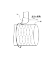
- FIG. 2 is an explanatory diagram for explaining an outline of vibration processing control.
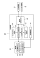
- FIG. 2 is a block diagram showing the configuration of a control system of the machine tool.
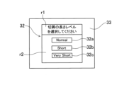
- FIG. 11 is a schematic diagram showing an example of a chip length selection section displayed on a touch panel.
- FIG. 4 is a diagram showing an example of parameter data stored in a parameter storage unit.
- 1 is a graph showing an example of a trajectory of a cutting tool during vibration machining.
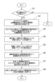
- 5 is a flowchart showing the contents of vibration processing control executed by the control device.
- FIG. 5 is a view corresponding to FIG. 4 and shows a second embodiment.
- FIG. 5 is a view corresponding to FIG.
- FIG. 13 is a schematic diagram showing an example of an input screen displayed on a touch panel by pressing a free setting button in embodiment 3.
- FIG. 13 is an example of an input screen displayed on an operation panel of a machine tool according to a fourth embodiment.
- FIG. 13 is a block diagram showing the configuration of a machine tool according to a fourth embodiment. 13 is an example of a graph screen displayed on an operation panel of a machine tool according to a first modified example of the fourth embodiment. 13 is another example of a graph screen displayed on the operation panel of the machine tool of the first modified example of the fourth embodiment. 4 is an example of an NC program created by a programming unit. 13 is an example of a guidance screen displayed on an operation panel of a machine tool according to a second modified example of the fourth embodiment.
- FIG. 11 is a block diagram showing the configuration of a machine tool and its peripheral devices in another embodiment.
- (Embodiment 1) 1 is a schematic diagram showing an overview of a machine tool 1 according to the present embodiment.
- the machine tool 1 is an NC lathe that performs turning by rotating a workpiece W and bringing a cutting tool 3 into contact with the peripheral surface of the workpiece W, and has a chip breaking function that breaks chips generated during turning by vibrating (advancing and retreating) the cutting tool 3 in the feed direction (direction of the rotation axis of the workpiece W).
- the direction along the rotation axis of the workpiece W is defined as the Z-axis direction
- the vertical direction perpendicular to the Z-axis direction is defined as the X-axis direction
- the direction perpendicular to both the X-axis and Z-axis is defined as the Y-axis direction.
- the machine tool 1 has a spindle 2, a headstock 5 that rotatably holds the spindle 2, a cutting tool 3, and a tool holder 4 that holds the cutting tool 3.
- a chuck 6 for gripping the workpiece W is provided at the tip of the spindle 2.
- the spindle head 5 has a built-in spindle motor (not shown) that rotates the spindle 2, and is fixed on the bed of the machine tool 1 (not shown).
- the spindle motor is composed of, for example, a servo motor, and is driven by a current supplied from a spindle drive amplifier (not shown).
- the spindle drive amplifier supplies the spindle motor with a current corresponding to a control signal transmitted from a control device 20 (described later).
- the spindle motor and spindle drive amplifier constitute a spindle drive unit 11 (see FIG. 3 described later), which functions as a rotation drive unit that rotates the cutting tool 3 and the workpiece W relatively along the circumferential direction of the workpiece W.
- the cutting tool 3 is a turning tool and is fixed to the tool holder 4.
- the tool holder 4 is moved in the X-, Y-, and Z-axis directions by the tool feed drive 10 (see FIG. 3 described later).
- the tool feed drive 10 has an X-axis feed mechanism, a Y-axis feed mechanism, and a Z-axis feed mechanism (none of which are shown) that perform feed operations in the X-, Y-, and Z-axis directions.
- Each feed mechanism is, for example, a combination of a ball screw and a servo motor.
- the tool feed drive 10 also has a feed drive amplifier (not shown) that supplies current to the corresponding servo motor, and each feed drive amplifier supplies a current to each servo motor according to a control signal transmitted from the control device 20 described later, and each servo motor is driven by the supplied current.
- the workpiece W rotates together with the spindle 2 around the axis of the spindle 2 under the driving of the spindle drive unit 11, and the tool holder 4 is driven and fed in the Z-axis direction under the driving of the tool feed drive unit 10.
- the tool holder 4 is driven in one direction from the tip side to the base end side of the workpiece W, but in the machine tool 1 of this example, the tool holder 4 is driven while vibrating back and forth in the Z-axis direction (advancing and retreating vibration).
- the cutting processing portion is overlapped during the forward movement and the return movement, and the chips are broken at the overlapping portion. In this way, the turning of the workpiece W is performed while breaking up the chips.
- the machine tool 1 has a control device (numerical control device) 20.
- the control device 20 is connected to the operation panel 30, the tool feed drive unit 10, and the spindle drive unit 11 so as to be able to send and receive signals.
- the operation panel 30 has an operation section that allows the operator to issue various operation commands and various settings to the machine tool 1, and transmits operation signals to the control device 20 in response to the operator's operation.
- This operation section includes, for example, a machining start button 31 for causing the machine tool 1 to start machining operations based on an NC program, and a chip length selection section 32 for selecting the length level of chips generated during turning.
- the chip length selection section 32 is displayed on a touch panel 33 (see FIG. 4) provided on the operation panel 30 under the control of the display control section 26 described below.
- This touch panel 33 functions as a display section that displays an operation screen, and also functions as an input section that inputs information (data) via the operation screen.
- the chip length selection section 32 is a selection screen that serves as an operation screen, and also functions as a reception section that receives selection instructions.
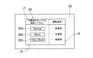
- FIG 4 is a schematic diagram showing an example of the chip length selection section 32 displayed on the touch panel 33.
- the chip length selection section 32 consists of a message display area r1 that prompts the operator to select a chip length level, and a selection area r2 for selecting the chip length level.
- selection area r2 displays selection buttons 32a to 32c corresponding to three length levels, "Normal”, “Short”, and "Very Short".
- Each selection button 32a to 32c functions as a selection operation section.
- the relationship between the chip lengths can be expressed as an inequality: "Normal” > "Short” > "Very short”.
- a length level corresponding to 0.5 chip breaks per rotation of the workpiece W is defined as "Normal”
- a length level corresponding to 1.5 chip breaks is defined as “Short”
- a length level corresponding to 2.5 chip breaks is defined as “Very Short.”
- the touch panel 33 detects the operation of each of the selection buttons 32a to 32c and transmits the operation signal to the control device 20.
- control device 20 has an NC program storage unit 21, an NC program analysis unit 22, a vibration condition calculation unit 23, a parameter storage unit 24, a drive signal generation unit 25, and a display control unit 26.
- the control device 20 is made up of a computer having a CPU, ROM, and RAM, and the NC program storage unit 21 and the parameter storage unit 24 are configured from non-volatile storage media such as ROM or a magnetic storage device, and the functions of the other functional units are realized by computer programs.
- the control device 20 functions as a drive control unit and a display control device.
- the NC program memory unit 21 stores NC programs for controlling the operation of the tool feed drive unit 10 and the spindle drive unit 11 of the machine tool 1.
- the NC program analysis unit 22 When the NC program analysis unit 22 receives an operation signal from the machining start button 31 provided on the operation panel 30, it executes the NC program stored in the NC program storage unit 21. When executing the NC program, the NC program analysis unit 22 extracts operation commands related to the tool feed drive unit 10 and the spindle drive unit 11, and transmits the extracted operation commands to the drive signal generation unit 25.
- the vibration condition calculation unit 23 calculates the vibration conditions (in this example, the vibration frequency f (Hz) and the vibration amplitude A (mm)) for adjusting the length of the chips generated during turning to the selected length level based on the length level selected by the chip length selection unit 32 of the operation panel 30 and the parameter data D (see FIG. 5) stored in the parameter storage unit 24.
- the vibration conditions in this example, the vibration frequency f (Hz) and the vibration amplitude A (mm)
- the parameter data D stored in the parameter storage unit 24 includes two parameters: a break number parameter I that indicates the number of times the chip breaks per one rotation of the workpiece W, and an amplitude parameter K that indicates the ratio of the total amplitude to the feed amount of the cutting tool 3 per one rotation of the workpiece W.
- the break number parameter I and the amplitude parameter K are associated with each of the chip length levels “Normal”, “Short”, and “Very Short” and are stored as table data.
- the break number parameters for "Normal”, “Short”, and “Very Short” are 0.5, 1.5, and 2.5, respectively, and the amplitude parameter K is fixed at 1.4.
- This graph is a graph of the tip trajectory (machining path) of the cutting tool 3 shown by the two-dot chain line in FIG. 2, with the horizontal axis indicating the phase angle around the axis of the workpiece W, and the vertical axis indicating the movement amount of the cutting tool 3 in the Z-axis direction.
- the number of times the trajectory of the cutting tool 3 overlaps during forward and reverse movements i.e., the number of times the chips are broken
- the number of breaks parameter I is 2.5.
- the vibration condition calculation unit 23 recognizes the chip length level selected by the chip length selection unit 32 based on the operation signal received from the touch panel 33 of the operation panel 30. The vibration condition calculation unit 23 then identifies the number of breaks parameter I and the amplitude parameter K that correspond to the recognized length level from the parameter data D (see FIG. 5) stored in the parameter storage unit 24.
- the vibration condition calculation unit 23 determines the vibration frequency f [Hz] of the cutting tool 3 in the Z-axis direction based on the specified number of cuts parameter I and the rotation speed S (rpm) of the workpiece W extracted by the NC program analysis unit 22, using the following formula (1):
- the vibration condition calculation unit 23 determines the vibration amplitude A of the cutting tool 3 based on the identified amplitude parameter K and the feed amount F (mm/revolution) of the cutting tool 3 per rotation of the workpiece W, using the following equation (2).
- feed amount F (mm/1 revolution) is extracted from the NC program by the NC program analysis unit 22.
- This feed amount F (mm/1 revolution) is the feed rate when performing normal cutting that does not include a vibration component (see the dashed line in FIG. 6).
- the drive signal generating unit 25 generates a drive signal (control signal) for driving the spindle 2 at the rotation speed S (rpm) included in the operation command for the spindle driving unit 11, based on the operation command extracted by the NC program analyzing unit 22, and transmits the generated drive signal to the spindle driving unit 11.
- the drive signal generating unit 25 also combines the Z-axis feed operation command without vibration components extracted by the NC program analyzing unit 22 with a vibration operation command including the vibration frequency f (Hz) and vibration amplitude A (mm) calculated by the vibration condition calculating unit 23, and transmits a drive signal (control signal) corresponding to the combined operation command to the tool feed driving unit 10.
- the display control unit 26 controls the display content of the touch panel 33 provided on the operation panel 30.
- the display control unit 26 displays the chip length selection unit 32 on the touch panel 33 when the power supply of the machine tool 1 is turned on.
- step S1 the NC program analysis unit 22 determines whether the machining start button 31 has been pressed based on the operation signal from the operation panel 30, and if the determination is NO, it returns, whereas if the determination is YES, it proceeds to step S2.
- step S2 the NC program analysis unit 22 extracts operation commands related to the operation of the spindle drive unit 11 (e.g., the rotation speed S (rpm)) and operation commands related to the operation of the tool feed drive unit 10 (e.g., the movement position of the cutting tool 3 in the Z-axis direction, the feed amount F (mm/1 rotation), etc.) based on the NC program stored in the NC program storage unit 21, and transmits the extracted operation commands to the drive signal generation unit 25.
- operation commands related to the operation of the spindle drive unit 11 e.g., the rotation speed S (rpm)
- operation commands related to the operation of the tool feed drive unit 10 e.g., the movement position of the cutting tool 3 in the Z-axis direction, the feed amount F (mm/1 rotation), etc.
- step S3 the drive signal generating unit 25 generates a drive signal corresponding to the operation command for the spindle drive unit 11 received from the NC program analyzing unit 22 in step S2, and transmits the generated drive signal to the spindle drive unit 11.
- the spindle drive unit 11 operates in response to this drive signal, and rotates the spindle 2 at the rotation speed S (rpm) commanded by the NC program.
- step S4 the vibration condition calculation unit 23 recognizes the chip length level currently selected by the chip length selection unit 32 on the operation panel 30.
- step S5 the vibration condition calculation unit 23 reads the number of breaks parameter I and the amplitude parameter K corresponding to the chip length level recognized in step S4 from the parameter data D (see FIG. 5) stored in the parameter storage unit 24.
- step S6 the vibration condition calculation unit 23 calculates the target vibration frequency f (Hz) and vibration amplitude A (mm) during vibration processing based on the number of divisions parameter I and amplitude parameter K read in step S5, and transmits this calculation result to the drive signal generation unit 25.
- the calculation process of this vibration frequency f (Hz) and vibration amplitude A (mm) is performed based on the above-mentioned formulas (1) and (2).
- step S7 the drive signal generating unit 25 generates a vibration operation command including the vibration frequency f (Hz) and vibration amplitude A (mm) received from the vibration condition calculating unit 23, and synthesizes the generated vibration operation command with the feed operation command of the tool feed driving unit 10 extracted by the NC program analyzing unit 22 in step S2.
- step S8 a drive signal is generated according to the operation command synthesized in step S7, and the generated drive signal is sent to the tool feed drive unit 10. After the processing of step S8 is completed, the process returns.
- the control device 20 specifies the number of breaks parameter I and the amplitude parameter K corresponding to the selected chip length level, and based on the specified number of breaks parameter I and the amplitude parameter K, the tool feed drive unit 10 determines the vibration frequency f (Hz) and vibration amplitude A (mm) in the Z-axis direction of the tool holding unit 4, and transmits a drive signal (control signal) to the tool feed drive unit 10 to realize the determined vibration frequency f (Hz) and vibration amplitude A (mm).
- the tool holding unit 4 moves in the Z-axis direction at the feed amount F (mm/1 rotation) commanded by the NC program, while performing the vibration operation in the Z-axis direction, whereby the cutting tool 3 performs turning of the workpiece W, and the chip length is controlled to the length level selected in the chip length selection unit 32.
- the operator can easily set the length of the chips generated during workpiece machining by simply selecting the chip length level from among three predetermined length levels in the chip length selection unit 32 without having to set vibration-related parameters such as the number of breaks parameter I and the amplitude parameter K by himself/herself. Therefore, even an operator with a low level of proficiency who does not understand the meaning of the number of breaks parameter I and the amplitude parameter K can easily set the length of the chips generated during turning with a simple operation, and can easily perform such vibration machining.
- (Embodiment 2) 8 shows the second embodiment.
- the display content of the chip length selection unit 32 is different from that of the first embodiment.
- the same components as those in the first embodiment are denoted by the same reference numerals, and detailed description thereof will be omitted.
- the chip length selection unit 32 has a load display area r3 in addition to the message display area r1 and selection area r2.
- the load display area r3 is located adjacent to the right side of the selection area r2.
- the load display area r3 displays the magnitude level of the driving load of the tool feed drive unit 10 to realize the chip length level labeled on each selection button 32a to 32c.
- the load display area r3 displays the operating load of the tool feed drive unit 10 when vibration machining control is performed based on the number of cuttings parameter I corresponding to each chip length level, in other words, the magnitude level of the driving load.
- the magnitude levels are distinguished into three levels: “low load”, “medium load”, and “high load”, and “low load” is displayed next to the “Normal” selection button 32a, “medium load” is displayed next to the “Short” selection button 32b, and “high load” is displayed next to the “Very Short” selection button 32c.
- the operator can easily recognize the magnitude of the drive load acting on the tool feed drive unit 10 due to the selection. Therefore, for example, when the continuous operation time of the machine tool 1 is long, if the operator wants to reduce the drive load acting on the tool feed drive unit 10 as much as possible, even if the operator wants to select "Very Short” as the chip length level, he or she can take a compromise measure such as selecting "Short” or “Normal” to prioritize reducing the drive load on the tool feed drive unit 10, or select "Very Short” as the chip length level after knowing that the load level is high.
- the operator can recognize the drive load acting on the tool feed drive unit 10 in advance and appropriately select the chip length level without having to think complicatedly, which simplifies operation and improves convenience.
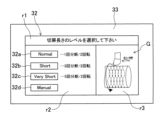
- Embodiment 3 9 shows embodiment 3. This embodiment is different from embodiment 1 in that the chip length selection unit 32 has a free setting button 32d for setting the chip length to an arbitrary length.
- the chip length selection section 32 has selection buttons 32a to 32c for selecting the chip length level, as well as a free setting button 32d that is labeled "Manual.”
- the display control unit 26 When the display control unit 26 receives an operation signal indicating that the free setting button 32d has been selected and operated from the touch panel 33, it displays a chip length input screen 34 (see FIG. 10) below the chip length selection unit 32 on the touch panel 33.
- This input screen 34 displays a message prompting the input of the number of times the chip will be broken per given rotation (in FIG. 10, as an example, the number of times the chip will be broken per two rotations of the work), and an input box 32e.
- the free setting button 32d and input box 32e function as an input operation unit (input unit) and a receiving unit that receives an instruction to select the chip length.
- a machining image diagram G (see FIG. 9) that allows the operator to visually understand the image of chip breakage is displayed to the right of selection area r2 in chip length selection section 32. This allows the operator to roughly imagine the number of breaks to be input into input box 32e and the chip length corresponding to this number of breaks. Also, in this example, the number of breaks per given rotation of the workpiece W (in this example, the number of breaks per two rotations of the workpiece W) is displayed to the right of each selection button 32a to 32c displayed in selection area r2. Therefore, the operator can refer to these displays to determine the number of breaks to input into input box 32e.
- the vibration condition calculation unit 23 calculates the number of divisions parameter I based on the input number of divisions.
- the amplitude parameter K is stored in advance as a fixed value in the parameter storage unit 24. This fixed value may be 1 or more, and is set to, for example, 1.4 in this example.
- the vibration condition calculation unit 23 calculates the vibration frequency f (Hz) and vibration amplitude A (mm) in the vibration processing control based on the amplitude parameter K, which is the fixed value, and the calculated number of divisions parameter I.
- the vibration condition calculation unit 23 transmits a vibration operation command including the calculated vibration frequency f (Hz) and vibration amplitude A (mm) to the drive signal generation unit 25, and the drive signal generation unit 25 generates a drive signal corresponding to the received vibration operation command as described in the first embodiment, and transmits the generated drive signal to the tool feed drive unit 10.
- the control device 20 of this embodiment is configured to determine vibration conditions based on the input value of the number of severances, and to execute vibration processing control based on the determined vibration conditions.
- the operator can set the chip length generated during turning to any length other than the three length levels corresponding to the selection buttons 32a to 32c.
- the operator can press the free setting button 32d and input the number of cuts in the input box 32e as necessary, and can set the chip length more precisely.
- (Embodiment 4) 11 shows a fourth embodiment.
- This embodiment differs from the above-mentioned embodiments in that an input box 35s for inputting a frequency magnification is also used as a chip length selection section 32.
- the frequency magnification has the same meaning as the above-mentioned number of divisions parameter.
- This frequency multiplier input box 35s is provided on an input screen 35 (described below) that is displayed on the touch panel 33.
- the machine tool 1 has a first control device 120 that controls the movement of the tool 3a and the workpiece W.
- the first control device (numerical control device) 120 has a drive control unit 122 that executes (interprets) an NC program and sends drive signals (control signals) to the spindle drive unit 11 and the tool feed drive unit 10, and a memory unit 121 that stores programs and the like for functioning as the drive control unit 122.
- the spindle drive unit 11 and the tool feed drive unit 10 receive signals from the first control device 120 and move the workpiece W and the tool 3a.
- the drive control unit 122 of the first control device 120 executes (analyzes) the NC program stored in the memory unit 121 to create operation commands from the operation codes of the NC program, and drives the spindle drive unit 11 and the tool feed drive unit 10 based on the operation commands.
- the first control device 120 performs these drive control processes and storage processes using a calculation means such as a CPU or LSI.
- the machine tool 1 further includes a second control device 140 that controls the display of the display unit 132.
- the second control device 140 includes a display control unit 141 that controls the display on the screen of the display unit 132, a storage unit 142 that stores the display format and data to be displayed, and a programming unit 143 that creates NC programs.
- the display unit 132 corresponds to the touch panel 32 described above, and has the same configuration.
- the display unit 132 and the second control device 140 constitute an NC program creation device.
- the storage unit 142 of the second control device 140 further stores a program for supporting the creation of an NC program and a program related to the display of the input screen 35 for support.
- the display control unit 141 of the second control device 140 operates these programs and supports the creation of an NC program via the display screen.
- the programming unit 143 creates an NC program based on information such as conditions set from the NC program creation support screen.
- the programming unit 143 also has a function for directly writing NC codes such as G codes and M codes to directly create an NC program, a function for editing an NC program, and a function for inserting G codes and M codes into specific lines or blocks of an existing NC program (code insertion unit 144).
- the functions for directly creating an NC program, editing an NC program, and inserting G codes and M codes into specific lines or blocks of an existing NC program are collectively referred to as NC program creation functions, and the programming unit 143 is a creation unit that creates an NC program.
- the second control device 140 executes these storage processes, display control processes, and programming processes using a calculation means such as a CPU or LSI that is different from the calculation means of the first control device 120.
- the operation panel 130 is also provided with a program execution button 131 and the above-mentioned display unit 132, which displays a screen showing the NC program, keyboard, and the like. While checking the display on the display unit 132, the operator can perform operations such as various settings related to machining and creating NC programs on the operation panel 130.
- the drive control unit 122 executes the specified NC program. That is, the drive control unit 122 reads out the specified NC program stored in the memory unit 121, and controls the spindle drive unit 11 and the tool feed drive unit 10 based on the read NC program, thereby performing machining.
- NC program An outline of how to create an NC program including a code related to vibration will be described.
- the machining path of the turning process when the NC program for vibration machining is executed by the machine tool 1 is similar to the graph in Fig. 6.
- the horizontal axis of the graph indicates the phase angle of the workpiece W around the Z axis
- the vertical axis indicates the movement amount of the cutting tool 3 in the Z axis direction.
- the drive control unit 122 of this embodiment performs turning by controlling the relative movement between the workpiece W and the tool 3a based on an NC program, as shown in this graph.
- the drive control unit 122 drives and vibrates the tool holding unit 4 in the Z-axis direction (the direction along the axis of the spindle 2) relative to the workpiece W based on the NC program, while feeding the tool.
- the machining point trajectory (see Figure 6) of the tool 3a held by the tool holding unit 4 traces a vibration waveform that is approximately sinusoidal.
- the NC program uses G code and M code to command feeding in the Z-axis direction, and also commands the vibration at that time to be the vibration shown in Figure 6.
- the drive control unit 122 accurately executes the contents of the command codes of the NC program, and does not set new machining paths or new command codes within the drive control unit 122 (itself).
- amplitude magnification K has the same meaning as the amplitude parameter described above
- frequency magnification I has the same meaning as the number of divisions parameter described above.
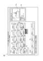
- FIG. 11 is a diagram of a creation support screen for creating an NC program that includes these two conditions.
- the frequency magnification I and amplitude magnification K are displayed on the tool condition setting screen of the creation support screen for creating an NC program, but this is not limited to this.
- This creation support screen provides input and selection fields for tool conditions such as tool, tool number (T code), cutting speed, feed, cutting depth, command point, chip breaking, and vibration axis.
- this screen also provides a selection field for the frequency magnification and an input field for the amplitude magnification.
- the programming unit 143 When creating an NC program, select Enable in the chip breaking selection field, select the frequency multiplier, enter the amplitude multiplier, and after entering other conditions on the creation support screen, press the NC program button 35z displayed in the bottom right, and this information will be sent to the programming unit 143.
- the programming unit 143 obtains information necessary for machining, such as the shape of the workpiece, and performs calculations from this information to create an NC program.
- the created NC program is sent to the memory unit 142 of the second control device 140 and stored therein.
- the second control device 140 When the operator of the machine tool 1 selects this created program on the operation panel 130 and presses the program execution button 131 provided on the operation panel 130, the second control device 140, which receives input from the operation panel 130, transmits the NC program stored in the memory unit 142 to the first control device 120.
- the first control device 120 receives the NC program, analyzes its contents, and issues commands to drive the spindle drive unit 11 and the tool feed drive unit 10 based on the NC program. This controls the movement of the tool 3a and workpiece W attached to the machine tool 1, and performs turning. In this way, with the machine tool 1 of this example, even an operator who does not have accurate knowledge of vibration cutting or NC codes related to vibration cutting can easily perform effective vibration cutting.
- the first modified example is an example in which program creation support is performed by dialogue programming. Since a program creator can create a program in a dialogue format, the program creator can create a program without understanding details such as G-code.
- a dialogue programming application is started as a program creation application (software)
- an input screen 35 is displayed. Since it is a dialogue format, there are items such as shape setting, processing setting, measurement setting, and tool setting, and the items required for the program to be created are selected and conditions are set.
- an NC program is created by a programming means from the set conditions.
- a contour input screen for the part to be processed is displayed, and the contour of the part (finished product) is drawn, and the shape information of the part is input and set.
- the shape setting may not be in the form of drawing the contour of the part, but may be in the form of importing a CAD drawing of the part (finished product) and setting the shape information of the part. This allows the shape information required for NC program creation to be set on the shape setting screen.
- necessary settings are made according to the NC program to be created. For example, if an NC program for processing is to be created, in addition to shape setting, processing setting and tool setting are made.
- the programming means creates and outputs an NC program from the conditions (information) set in the shape setting, processing setting, and tool setting.
- the conditions for creating vibration-related code are set on the tool setting input screen 35.
- the tool setting input screen 35 is a screen for setting information related to the tool 3 (tool conditions, tool position, etc.).
- the input screen 35 in FIG. 11 has input boxes 35a to 35u for inputting the tool name, machining type, tool ID, T code, cutting speed, feed rate, cutting depth, command point, nose R, cutting edge angle, pocket angle, pocket, area designation, flank wear, chip breaking, reference machining conditions, reference rotation speed, vibration axis, frequency magnification, amplitude magnification, and maximum load value.
- the input screen 35 also includes an input box 35v related to the tool position. In the example of FIG. 11, "General purpose outer diameter" has been selected as the tool name from the pull-down menu.
- the "vibration axis" input box 35r shown in the tool conditions is a pull-down box for selecting whether the cutting tool 3 is not vibrated or the direction of vibration when the cutting tool 3 is vibrated.
- "none (V0)" is displayed, which does not vibrate the cutting tool 3.
- the vibration axis is the X-axis
- it is displayed as "X-axis (X0)”
- the vibration axis is the Z-axis
- Z0 Z-axis
- X-axis Z-axis if the two axes, the X-axis and the Z-axis, are vibrated simultaneously, it is displayed as "X-axis Z-axis (XZ)”.
- the "Chip breaking" input box 35 Azure shown in the tool conditions allows the user to select whether to enable or disable the chip breaking function using a pull-down menu.
- a pull-down menu with “Enable” and “Disable” tabs is displayed, allowing the operator to select one of the two tabs.
- a first guidance area 35w is provided at the top right of the input screen 35 to explain the input contents of the selected input box.
- the first guidance area 35w displays an image (still image, video, etc.) that allows the program creator to visually and intuitively understand the conditions that can be set. In the example of FIG. 11, an image is displayed that allows the user to visually and intuitively understand that the length of the chip changes depending on the input selection of the frequency multiplier.
- the second guidance area 35x displayed below the first guidance area 35w is a guidance field that explains the correspondence between the frequency multiplier I value and the chip length level when performing chip breaking (chip breaking) to shorten long chips.
- the chip length is written as "NORMAL (0.5)", “SHORT (1.5)”, and “VERY SHORT (2.5)", providing guidance to intuitively understand the chip length. It is also explained that there is also an optional input that allows the user to directly input a numerical value for program creators with a lot of experience in program creation.
- the numbers in parentheses in the guidance column represent the numerical value of the frequency multiplication factor I corresponding to each chip length level, and are also the numerical values written into the NC program of this embodiment when the NC program is created.
- the second guidance area 35x may be an explanatory column that explains the diagram of the first guidance area 35w, or an explanatory column that supplements the diagram of the first guidance area 35w.
- the programmer refers to the contents of the first guidance area 35w and the second guidance area 35x to recognize the relationship between the frequency multiplication factor I and the chip length level, and performs an input operation in the input box 35s. That is, if the programmer wants to set the chip length to "NORMAL", for example, he selects "NORMAL (0.5)” from the pull-down menu provided in the frequency multiplication factor input box 35s. In this example, when the programmer selects (touches) the " ⁇ " mark provided at the right end of the frequency multiplication factor input box 35d, three pull-down menus of "NORMAL (0.5)”, “SHORT (1.5)”, and “VERY SHORT (2.5)” are displayed, and one of these three can be selected. If an arbitrary value is to be input, the programmer moves the cursor to the input box, selects (or touches the screen), and can input a value from the keyboard.
- an NC program can be created by the programming means by pressing the NC program button 35z. Since the NC program itself is executed by various machine tools, a screen may be displayed on the machine tool on which the operator of the machine tool 1 enters and executes the NC program, allowing the operator to easily visually check whether the NC program can be used with the machine tool 1 being used. With this input method, even an operator who does not have accurate knowledge of vibration cutting or NC codes related to vibration cutting can easily set up the vibration cutting, including setting the chip length, and can easily create an NC program for performing vibration cutting.
- a confirmation screen is displayed, allowing the programmer or the operator of the machine tool 1 to confirm that the NC program to be created can be used on the machine tool 1 on which it is to be executed.
- a confirmation graph screen 37 is displayed on the display unit 132 indicating whether the program can be safely used on the machine tool 1 based on the feed rate entered in input box 35f, the vibration conditions entered in input boxes 35r to 35t, the automatically calculated value of the rotation speed of the spindle 2, etc.
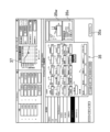
- FIG. 13A shows an example of a confirmation graph screen 37 displayed on the display unit 132.
- a line is displayed in a graph with the rotation speed on the vertical axis and the feed rate on the horizontal axis, dividing a safe area (stable area) from a non-recommended area (unstable area).
- the safe area is a machining area where machining can be performed without placing unnecessary load on the machine tool 1 or tools, for example, a machining area where regenerative chatter does not occur
- the non-recommended area is a machining area where unnecessary load is placed on the machine tool 1 or tools, for example, a machining area where regenerative chatter may occur. If a load is placed on the tool 3a, the life of the tool 3a will be shortened and the tool will need to be changed more frequently, so it is desirable to perform machining without placing unnecessary loads.
- the display control unit 141 plots and displays values calculated based on conditions set on the input screen, etc., on this graph. If the plot point is located in the non-recommended area above the division line, the display control unit 141 displays the plot point as a black circle (see FIG. 13A). On the other hand, if the plot point is located in the safe area below the division line, the display control unit 141 displays the plot point as a white circle (see FIG. 13B). As shown in FIGS. 13A and 13B, the right side of the confirmation graph screen 37 displays the rotation speed of the spindle 2, the feed speed of the tool 3a, the chip cutting length, and the amplitude magnification K, which are the basis for calculating this operating point.
- the rotation speed of the spindle 2 is input from the input box 35q
- the feed speed of the tool 3a is input from the input box 35f
- the chip cutting length is selected by the input box 35s
- the amplitude magnification K is input from the input box 35t.
- the programmer checks this display, and if it is confirmed that the machine tool 1 being used can be operated safely, he or she presses the NC program button 35z to create an NC program using the programming means. If it is not safe, as shown in FIG. 13A, these input values and selections are reset to a safe state.
- the operator of the machine tool 1 presses the program execution button 131 once he or she has confirmed that the NC program can be safely executed on the machine tool 1 being used.
- the program execution button 131 is pressed, the first control device 120 of the machine tool 1 analyzes the NC program and sends commands to the spindle drive unit 11 and tool feed drive unit 10, thereby causing the machine tool 1 to perform machining based on the NC program.
- the programming unit 143 creates an NC program based on the specification values entered via the input screen 35. At that time, if the chip breaking function is enabled, the programming unit 143 creates a code related to vibration from the set values of at least the vibration axis, frequency multiplication factor I, and amplitude multiplication factor K, and creates an NC program including this code.
- the programming unit 143 transmits the created NC program to the first control device 120.
- the first control device 120 analyzes the received NC program, transmits drive signals to the spindle drive unit 11 and the tool feed drive unit 10, and causes the machine tool 1 to perform machining of the workpiece W.
- FIG. 14 shows an example of an NC program created by the programming unit 143.
- the operation commands (G-codes) for executing vibration machining control are incorporated in lines 83, 85, and 87.
- Chip Breaking code “Chip Breaking ON (LXX, LZZ, Frequency, Amplitude, ID)" may be used.
- LXX is the X-axis
- LZZ is the Z-axis
- Frequency is the frequency of the sin2 function as a vibration function per one spindle revolution
- Amplitude is the amplitude of the sin2 function
- ID is the number of a static synchronization action required to initiate and periodically call a technology cycle.
- the programming means inserts the Chip Breaking code into the NC program if the chip breaking function is enabled on the input screen 35, sets LXX and LZZ if the X-axis and Z-axis are selected as the vibration axes, converts the value set by the frequency multiplier to the corresponding frequency and sets the Frequency by replacing it with a numerical value, and converts the value set by the amplitude multiplier to the corresponding amplitude and sets the Amplitude by replacing it with a numerical value.
- the second control device 140 of the second modification has a programming means including a code insertion means that can execute a process of inserting a chip breaking function code into an NC program upon receiving an input from the guidance screen 36 (see FIG. 15) displayed on the display unit 132. That is, the second control device 140 has, in addition to a display control unit 141 and a storage unit 142, a programming unit 143 (an example of a programming means) that includes a code insertion unit 144 (an example of a code insertion means).
- the display control unit 141 displays a program editing screen on the display unit 132.
- the program editor can display the program, select the part to be edited, and directly edit the program, but in this modified example, icons of technology cycles (functions set to realize a specific machining, etc.) are displayed and a selection screen for selecting the function to be edited is displayed first.
- the selection screen displays icons of technology cycles such as chip breaking, multi-thread 2.0, keyway broaching, application tuning cycle, and gear hobbing so that the function to be edited can be selected.
- the display control unit 141 displays a guidance screen 36 for the function selected on the editing screen on the display unit 132.
- FIG. 15 shows that chip breaking of the technology cycle has been selected and the guidance screen 36 for chip breaking is displayed.
- the guidance screen 36 in FIG. 15 has a program display area 36a window on the left side of the screen, and a guidance area 36b window on the right side of the screen.
- the program display area 36a displays an NC program entered from the keyboard or an NC program stored in the memory unit 121.
- the program display area 36a in FIG. 15 displays an NC program for turning that has been called up from the memory unit 121.
- the guidance area 36b includes an image (still image, video, etc.) that explains the function selected in the technology cycle, and an image area 36c that displays a written explanation of the selected function and guidance on input.
- the guidance area 36b also includes a guidance input area 36m.
- the guidance input area 36m in FIG. 15 includes six input boxes 36d to 36i.
- image area 36c in FIG. 15 images are displayed that allow visual understanding of the positional relationship between the workpiece W and the tool 3a, the rotation direction of the workpiece W, and the movement and vibration of the tool 3a.
- This image area 36c makes it easy to visually understand the chip breaking function, and the explanations and input guidance displayed around it make it easy to input and set values to be set, etc., in the guidance input area 36m.
- 2000 (rpm) is entered into input box 36e for specifying the rotation speed of the spindle 2
- 0.5 is entered into input box 36g for specifying (selecting) the frequency magnification I that determines the chip length
- 1.2 is entered into input box 36h for specifying (selecting) the amplitude magnification K.
- a code related to vibration is created, and this code is inserted into the line selected by the operator of the machine tool 1 in the program display area 36a.
- the operator may select the line not only by touch operation but also by operating the cursor keys, and the code insertion unit 144 identifies the position of the line (or block number) into which the code is to be inserted based on the signal of this touch operation or cursor operation. After identifying the position of the insertion line, the code insertion unit 144 receives an operation signal of the insert button 36j located in the upper right corner of the guidance screen 36, and then inserts the code related to vibration into the identified line in the NC program.
- vibration-related code has been inserted into lines 83, 85, and 87 of the NC program displayed in the program display area 36a.
- the inserted lines are displayed with a black label, and the characters of the operation command code are displayed in white.
- the code insertion unit 144 When the code insertion unit 144 receives an operation signal from the save button 36k located at the bottom right of the guidance screen 36, it stores the NC program after the operation command code has been inserted in the memory unit 142 of the second control device 140, and also transmits it to the first control device 120, where it is stored in its memory unit 121.
- the drive control unit 122 When the drive control unit 122 receives an NC program execution command from the operation panel 130 (a command indicating that the program execution button 131 has been pressed), it controls the operation of the spindle drive unit 11 and the tool feed drive unit 10 in accordance with an NC program stored in the memory unit 121, for example, that has been created or edited in the programming unit 143, or into which an operation command code has been inserted. As a result, cutting processing is performed multiple times using the tool 3a while the tool 3a vibrates in the X-axis direction based on the vibration conditions input by the operator.
- the operator can insert the desired code into any line (or block) in the NC program while viewing the NC program displayed in the program display area 36a of the guidance screen 36. This reduces the programming burden on the operator of the machine tool 1.
- the rotation mechanism of the machine tool 1 is configured with the spindle drive unit 11, and only the workpiece W is rotated by the spindle drive unit 11, but this is not limited thereto, and for example, the workpiece W may be fixed so as not to rotate, and the cutting tool 3 may be rotated about the Z axis, or both the workpiece W and the cutting tool 3 may be rotated about the Z axis.
- the rotation mechanism of the machine tool 1 may have any configuration as long as it rotates the cutting tool 3 and the workpiece W relatively in the circumferential direction of the workpiece W.
- the cutting tool 3 is driven in the Z-axis direction by the tool feed drive unit 10, but this is not limited thereto.
- the cutting tool 3 may be fixed so as not to move in the Z-axis direction, and only the workpiece W may be driven in the Z-axis direction, or both the cutting tool 3 and the workpiece W may be driven in the Z-axis direction.
- the feed drive unit of the machine tool 1 may have any configuration as long as it is configured to feed and move the cutting tool 3 and the workpiece W relatively along the Z-axis direction (along the axis of rotation).
- the cutting tool 3 is used to machine the workpiece W into a cylindrical shape, but this is not limited thereto.
- the workpiece W may be machined into a tapered shape in which the machining diameter changes in the Z-axis direction.
- the cutting tool 3 is used to turn the outer peripheral surface of the workpiece W, but this is not limited to this.
- the inner peripheral surface of a hollow workpiece W may be turned.
- the selection buttons 32a to 32c of the chip length selection section 32 are configured as soft keys displayed on the touch panel 33, but this is not limited thereto and may be configured as hard keys physically fixed to the operation panel 130, for example.
- the chip length selection unit 32 is configured to visually display the chip length levels that are candidates for selection on the touch panel 33, but this is not limited to this, and for example, the length levels that are candidates for selection may be presented by voice.
- the length levels "Normal”, “Short”, and “Very Short” are defined as lengths at which the number of times the chip breaks per rotation is 0.5, 1.5, and 2.5, respectively, but this is not limited to this.
- the number of breaks corresponding to each length level can be freely set to any value, and is not limited to this example.
- each length level may be defined, for example, as a ratio to the circumferential length of the outer surface of the workpiece W, without using the concept of the number of breaks.
- the chip length selection unit 32 is configured to be able to select from three length levels: “Normal,” “Short,” and “Very Short.” However, this is not limited to this, and the number of selectable length levels may be two, or four or more.
- the parameter storage unit 124 constitutes part of the control device 120, but this is not limited thereto, and the parameter storage unit 124 may be configured separately from the control device 120.
- the number of cuts per given rotation can be input from the input box 32e, but this is not limited to this.
- the ratio of the length of the chips to the circumference of the workpiece W may be input.
- the length of the chips may also be directly input into the input box 32e.
- the programming unit 143 is provided in the second control device 140, but this is not limited thereto.
- a programming unit 53 (a unit with the same functions as the programming unit 143) may be provided in the external computer 50.
- the display control unit 52 of the external computer 50 displays the input screen 35 on the display unit 132 of the operation panel 130.
- the programming unit 53 of the external computer 50 creates an NC program based on the vibration conditions input via the input screen 35.
- the programming unit 53 then transmits the created NC program to the first control device 120 and stores it in the memory unit 121.
- the code insertion unit 144 is provided in the second control device 140, but this is not limited thereto.
- the code insertion unit 54 (a unit with the same functionality as the code insertion unit 144) may be provided in the external computer 50.
- control device 120 of the machine tool 1 is also used as a display control device, but this is not limited to the above.
- the display control device may be configured as a separate unit from the control device 120 of the machine tool 1.
- the display control device may be configured, for example, as an external computer provided outside the machine tool 1.
- the present invention includes any combination of the above embodiments and modifications.
Landscapes
- Engineering & Computer Science (AREA)
- Physics & Mathematics (AREA)
- Human Computer Interaction (AREA)
- Manufacturing & Machinery (AREA)
- General Physics & Mathematics (AREA)
- Automation & Control Theory (AREA)
- Mechanical Engineering (AREA)
- Geometry (AREA)
- Numerical Control (AREA)
Priority Applications (3)
| Application Number | Priority Date | Filing Date | Title |
|---|---|---|---|
| CN202380074434.3A CN120092217A (zh) | 2022-10-24 | 2023-10-23 | Nc程序制作 |
| JP2024553038A JPWO2024090371A1 (cg-RX-API-DMAC7.html) | 2022-10-24 | 2023-10-23 | |
| EP23882576.4A EP4592779A1 (en) | 2022-10-24 | 2023-10-23 | Nc program creation |
Applications Claiming Priority (4)
| Application Number | Priority Date | Filing Date | Title |
|---|---|---|---|
| JP2022-169685 | 2022-10-24 | ||
| JP2022169685 | 2022-10-24 | ||
| JP2023178815 | 2023-10-17 | ||
| JP2023-178815 | 2023-10-17 |
Publications (1)
| Publication Number | Publication Date |
|---|---|
| WO2024090371A1 true WO2024090371A1 (ja) | 2024-05-02 |
Family
ID=90830998
Family Applications (1)
| Application Number | Title | Priority Date | Filing Date |
|---|---|---|---|
| PCT/JP2023/038153 Ceased WO2024090371A1 (ja) | 2022-10-24 | 2023-10-23 | Ncプログラム作成 |
Country Status (4)
| Country | Link |
|---|---|
| EP (1) | EP4592779A1 (cg-RX-API-DMAC7.html) |
| JP (1) | JPWO2024090371A1 (cg-RX-API-DMAC7.html) |
| CN (1) | CN120092217A (cg-RX-API-DMAC7.html) |
| WO (1) | WO2024090371A1 (cg-RX-API-DMAC7.html) |
Citations (5)
| Publication number | Priority date | Publication date | Assignee | Title |
|---|---|---|---|---|
| US20090107308A1 (en) * | 2007-10-16 | 2009-04-30 | Woody Bethany A | Methods and systems for chip breaking in turning applications using cnc toolpaths |
| WO2017051745A1 (ja) | 2015-09-24 | 2017-03-30 | シチズン時計株式会社 | 工作機械の制御装置及びこの制御装置を備えた工作機械 |
| WO2021014517A1 (ja) * | 2019-07-19 | 2021-01-28 | ヤマザキマザック株式会社 | 工作機械、工作機械の加工プログラム編集方法、及び工作機械の加工プログラム編集のためのプログラム |
| WO2021145378A1 (ja) * | 2020-01-16 | 2021-07-22 | ファナック株式会社 | 数値制御装置 |
| WO2022085114A1 (ja) * | 2020-10-21 | 2022-04-28 | 三菱電機株式会社 | 数値制御装置及び数値制御方法 |
-
2023
- 2023-10-23 WO PCT/JP2023/038153 patent/WO2024090371A1/ja not_active Ceased
- 2023-10-23 JP JP2024553038A patent/JPWO2024090371A1/ja active Pending
- 2023-10-23 CN CN202380074434.3A patent/CN120092217A/zh active Pending
- 2023-10-23 EP EP23882576.4A patent/EP4592779A1/en active Pending
Patent Citations (5)
| Publication number | Priority date | Publication date | Assignee | Title |
|---|---|---|---|---|
| US20090107308A1 (en) * | 2007-10-16 | 2009-04-30 | Woody Bethany A | Methods and systems for chip breaking in turning applications using cnc toolpaths |
| WO2017051745A1 (ja) | 2015-09-24 | 2017-03-30 | シチズン時計株式会社 | 工作機械の制御装置及びこの制御装置を備えた工作機械 |
| WO2021014517A1 (ja) * | 2019-07-19 | 2021-01-28 | ヤマザキマザック株式会社 | 工作機械、工作機械の加工プログラム編集方法、及び工作機械の加工プログラム編集のためのプログラム |
| WO2021145378A1 (ja) * | 2020-01-16 | 2021-07-22 | ファナック株式会社 | 数値制御装置 |
| WO2022085114A1 (ja) * | 2020-10-21 | 2022-04-28 | 三菱電機株式会社 | 数値制御装置及び数値制御方法 |
Also Published As
| Publication number | Publication date |
|---|---|
| EP4592779A1 (en) | 2025-07-30 |
| CN120092217A (zh) | 2025-06-03 |
| JPWO2024090371A1 (cg-RX-API-DMAC7.html) | 2024-05-02 |
Similar Documents
| Publication | Publication Date | Title |
|---|---|---|
| JP6719790B1 (ja) | Cadデータによるマシニングセンタの自動運転装置 | |
| EP2985664B1 (en) | Offset number setting device | |
| US20240280971A1 (en) | Nc program creation | |
| JPS624551A (ja) | 工具形状の自動描画方式 | |
| JP6638979B2 (ja) | 加工工程管理機能付き数値制御装置および加工工程管理プログラム | |
| JP4059411B2 (ja) | Nc工作機械の制御装置 | |
| US7089531B2 (en) | Method and device for generating or editing NC programs | |
| TW201740233A (zh) | 產生g代碼檔案儲存及執行加工的電腦數控工具機 | |
| KR101108211B1 (ko) | 복합선반용 파트프로그래밍 장치 및 복합 공정간 동기화 프로그램 생성방법 | |
| US20250153266A1 (en) | Combined machining apparatus, method to perform cutting and friction stir welding, and computer readable storage medium | |
| WO2024090371A1 (ja) | Ncプログラム作成 | |
| JP5307917B1 (ja) | インデックステーブル用制御装置 | |
| JP6444923B2 (ja) | 数値制御装置 | |
| JP2002529843A5 (cg-RX-API-DMAC7.html) | ||
| JP4037087B2 (ja) | 数値制御工作機械のねじ切り制御方法および制御装置とそれを組み込んだ数値制御工作機械 | |
| JP7827830B2 (ja) | 表示装置およびコンピュータ読み取り可能な記憶媒体 | |
| JP2000126937A (ja) | 放電加工におけるプログラミング装置の設定装置 | |
| WO2022269816A1 (ja) | 数値制御装置、画面作成システム、及び数値制御装置が読み取り可能な命令を記憶する記憶媒体 | |
| JP7114209B1 (ja) | 情報処理装置および情報処理プログラム | |
| JP2000158290A (ja) | 工作機械のnc加工プログラム作成方法および装置 | |
| US20260079472A1 (en) | Information processing apparatus, and method and program for generating nc program | |
| JP2025036247A (ja) | 数値制御工作機械の操作方法 | |
| KR100221564B1 (ko) | 최적의 가공조건을 결정할 수 있는 가공방법및 장치 | |
| JPS61257740A (ja) | 工具決定方式 | |
| JP2006079561A (ja) | 数値制御装置、数値制御方法、制御プログラム及び記録媒体 |
Legal Events
| Date | Code | Title | Description |
|---|---|---|---|
| 121 | Ep: the epo has been informed by wipo that ep was designated in this application |
Ref document number: 23882576 Country of ref document: EP Kind code of ref document: A1 |
|
| WWE | Wipo information: entry into national phase |
Ref document number: 2024553038 Country of ref document: JP |
|
| WWE | Wipo information: entry into national phase |
Ref document number: 202380074434.3 Country of ref document: CN |
|
| WWE | Wipo information: entry into national phase |
Ref document number: 2023882576 Country of ref document: EP |
|
| ENP | Entry into the national phase |
Ref document number: 2023882576 Country of ref document: EP Effective date: 20250425 |
|
| WWE | Wipo information: entry into national phase |
Ref document number: 202547046221 Country of ref document: IN |
|
| NENP | Non-entry into the national phase |
Ref country code: DE |
|
| WWP | Wipo information: published in national office |
Ref document number: 202380074434.3 Country of ref document: CN |
|
| WWP | Wipo information: published in national office |
Ref document number: 202547046221 Country of ref document: IN |
|
| WWP | Wipo information: published in national office |
Ref document number: 2023882576 Country of ref document: EP |