WO2024090144A1 - Method for producing partially divided carbon fiber bundle - Google Patents
Method for producing partially divided carbon fiber bundle Download PDFInfo
- Publication number
- WO2024090144A1 WO2024090144A1 PCT/JP2023/035865 JP2023035865W WO2024090144A1 WO 2024090144 A1 WO2024090144 A1 WO 2024090144A1 JP 2023035865 W JP2023035865 W JP 2023035865W WO 2024090144 A1 WO2024090144 A1 WO 2024090144A1
- Authority
- WO
- WIPO (PCT)
- Prior art keywords
- carbon fiber
- fiber bundle
- less
- protrusion
- partial
- Prior art date
Links
- 229920000049 Carbon (fiber) Polymers 0.000 title claims abstract description 508
- 239000004917 carbon fiber Substances 0.000 title claims abstract description 508
- VNWKTOKETHGBQD-UHFFFAOYSA-N methane Chemical compound C VNWKTOKETHGBQD-UHFFFAOYSA-N 0.000 title claims abstract description 499
- 238000004519 manufacturing process Methods 0.000 title claims abstract description 47
- 238000007380 fibre production Methods 0.000 claims abstract description 22
- 238000000034 method Methods 0.000 claims description 293
- 238000004513 sizing Methods 0.000 claims description 25
- 239000000835 fiber Substances 0.000 claims description 19
- 238000011144 upstream manufacturing Methods 0.000 claims description 12
- 238000007664 blowing Methods 0.000 claims description 9
- 239000002243 precursor Substances 0.000 claims description 8
- 238000002474 experimental method Methods 0.000 description 18
- 239000003677 Sheet moulding compound Substances 0.000 description 8
- 238000004381 surface treatment Methods 0.000 description 8
- 239000002699 waste material Substances 0.000 description 8
- 125000006850 spacer group Chemical group 0.000 description 6
- 238000001354 calcination Methods 0.000 description 5
- 238000004804 winding Methods 0.000 description 5
- 230000007423 decrease Effects 0.000 description 4
- 230000000694 effects Effects 0.000 description 4
- 229910001220 stainless steel Inorganic materials 0.000 description 4
- 239000010935 stainless steel Substances 0.000 description 4
- 229920000742 Cotton Polymers 0.000 description 3
- 229920002239 polyacrylonitrile Polymers 0.000 description 3
- 229910000831 Steel Inorganic materials 0.000 description 2
- 239000004918 carbon fiber reinforced polymer Substances 0.000 description 2
- 239000003795 chemical substances by application Substances 0.000 description 2
- 230000008602 contraction Effects 0.000 description 2
- 239000000428 dust Substances 0.000 description 2
- 238000010304 firing Methods 0.000 description 2
- 230000005484 gravity Effects 0.000 description 2
- 239000000463 material Substances 0.000 description 2
- 239000002184 metal Substances 0.000 description 2
- 230000002093 peripheral effect Effects 0.000 description 2
- 239000012779 reinforcing material Substances 0.000 description 2
- 229920005989 resin Polymers 0.000 description 2
- 239000011347 resin Substances 0.000 description 2
- 239000007858 starting material Substances 0.000 description 2
- 239000010959 steel Substances 0.000 description 2
- 239000000853 adhesive Substances 0.000 description 1
- 238000004026 adhesive bonding Methods 0.000 description 1
- 230000001070 adhesive effect Effects 0.000 description 1
- -1 and among them Substances 0.000 description 1
- 230000015572 biosynthetic process Effects 0.000 description 1
- 238000003763 carbonization Methods 0.000 description 1
- 238000005520 cutting process Methods 0.000 description 1
- 230000006866 deterioration Effects 0.000 description 1
- 238000010586 diagram Methods 0.000 description 1
- 125000000524 functional group Chemical group 0.000 description 1
- 238000005087 graphitization Methods 0.000 description 1
- 238000003780 insertion Methods 0.000 description 1
- 230000037431 insertion Effects 0.000 description 1
- 239000000314 lubricant Substances 0.000 description 1
- 238000004806 packaging method and process Methods 0.000 description 1
- 238000003672 processing method Methods 0.000 description 1
- 239000002994 raw material Substances 0.000 description 1
- 238000011084 recovery Methods 0.000 description 1
- 238000005245 sintering Methods 0.000 description 1
- 150000003384 small molecules Chemical class 0.000 description 1
- 230000000087 stabilizing effect Effects 0.000 description 1
- 238000006557 surface reaction Methods 0.000 description 1
Images


Classifications
-
- D—TEXTILES; PAPER
- D02—YARNS; MECHANICAL FINISHING OF YARNS OR ROPES; WARPING OR BEAMING
- D02G—CRIMPING OR CURLING FIBRES, FILAMENTS, THREADS, OR YARNS; YARNS OR THREADS
- D02G3/00—Yarns or threads, e.g. fancy yarns; Processes or apparatus for the production thereof, not otherwise provided for
- D02G3/02—Yarns or threads characterised by the material or by the materials from which they are made
- D02G3/16—Yarns or threads made from mineral substances
-
- D—TEXTILES; PAPER
- D02—YARNS; MECHANICAL FINISHING OF YARNS OR ROPES; WARPING OR BEAMING
- D02J—FINISHING OR DRESSING OF FILAMENTS, YARNS, THREADS, CORDS, ROPES OR THE LIKE
- D02J1/00—Modifying the structure or properties resulting from a particular structure; Modifying, retaining, or restoring the physical form or cross-sectional shape, e.g. by use of dies or squeeze rollers
- D02J1/18—Separating or spreading
Definitions
- the present invention relates primarily to a method for producing a partially split carbon fiber bundle.
- This application claims priority based on Japanese Patent Application No. 2022-173173 filed with the Japan Patent Office on October 28, 2022, and Japanese Patent Application No. 2023-120315 filed with the Japan Patent Office on July 24, 2023, the contents of which are incorporated herein by reference.
- CFRP The mechanical properties of CFRP obtained by curing a prepreg in which a random mat type reinforcing material made of chopped carbon fiber bundles, such as SMC (sheet molding compound), is impregnated with resin, are affected by the bundle size of the chopped carbon fiber bundles, i.e., the number of carbon fiber filaments that make up the bundle. SMC using chopped carbon fiber bundles with smaller bundle size as reinforcing material can give CFRP with better mechanical properties (Patent Document 1).
- partial division refers to partially dividing an original continuous fiber bundle into a plurality of sub-bundles.
- the objects of the present invention include the following: - To provide a technique for producing partially split carbon fiber bundles with stable quality. - To provide partially split carbon fiber bundles suitable as raw materials for SMC. - Prevent deterioration in the quality of the partially divided carbon fiber bundles due to problems during the partial division process. Preventing a decrease in the production efficiency of partially divided carbon fiber bundles due to problems during the partial division process.
- a method for producing partially split carbon fiber bundles in which carbon fiber bundles are continuously supplied from a carbon fiber production line to a partial splitting line connected to the carbon fiber production line, and are subjected to a partial splitting process in a partial splitting section provided in the partial splitting line.
- a method for manufacturing partially divided carbon fiber bundles by subjecting a carbon fiber bundle to a partial division process, the partial division process including intermittently piercing the carbon fiber bundle traveling along its own longitudinal direction with a protrusion of a division jig having a protrusion, the protrusion being formed by a needle, and the needle being inclined so as to fall downstream in the traveling direction of the carbon fiber bundle when pierced into the carbon fiber bundle.
- a method for manufacturing partially divided carbon fiber bundles by subjecting a carbon fiber bundle to a partial division process, the partial division process including intermittently piercing the carbon fiber bundle traveling along its own longitudinal direction with a protrusion of a division jig having a protrusion, the protrusion being formed of a plate, and when the plate is pierced into the carbon fiber bundle, the edge of the plate facing the upstream side in the running direction of the carbon fiber bundle is inclined so as to fall toward the downstream side in the running direction of the carbon fiber bundle in the portion where the plate is pierced into the carbon fiber bundle.
- a method for manufacturing partially divided carbon fiber bundles by subjecting a carbon fiber bundle to a partial division process, the partial division process including intermittently piercing the carbon fiber bundle traveling along its longitudinal direction with a protrusion of a division jig having a protrusion, the protrusion being formed of a plate, the plate-shaped protrusion having at least one convex corner with an interior angle of 90° or more but no convex corners with an interior angle of less than 90°, and the number of the convex corners of the protrusion with an interior angle of 90° or more that are pierced into the carbon fiber bundle does not exceed one in the partial division process.
- a method for manufacturing a partially divided carbon fiber bundle by subjecting a carbon fiber bundle to a partial division process, the partial division process including intermittently piercing the carbon fiber bundle running along its longitudinal direction with a protrusion of a division jig having a protrusion, the protrusion being formed of a plate, the plate-shaped protrusion having two right-angled corners, and only one of the two right-angled corners being pierced into the carbon fiber bundle in the partial division process.
- a method for manufacturing a partially divided carbon fiber bundle by subjecting a carbon fiber bundle to a partial division process, the partial division process including intermittently piercing the carbon fiber bundle running along its longitudinal direction with a protrusion of a division jig having a protrusion, the protrusion being formed using a rectangular plate, and in the partial division process, only one of the four right-angled corners of the rectangular plate is pierced into the carbon fiber bundle.
- a method for manufacturing a partially divided carbon fiber bundle by subjecting a carbon fiber bundle to a partial division process, the partial division process including swinging a division jig having a protrusion to intermittently pierce the protrusion into the carbon fiber bundle traveling along its own longitudinal direction.
- a method for manufacturing a partially divided carbon fiber bundle by subjecting a carbon fiber bundle to a partial division process, the partial division process including intermittently piercing the carbon fiber bundle traveling along its own longitudinal direction with a protrusion of a division jig having a protrusion, and blowing compressed air onto the protrusion of the division jig while the partial division process is being performed.
- a method for manufacturing a partially divided carbon fiber bundle by subjecting a carbon fiber bundle to a partial division process, the partial division process including intermittently piercing the carbon fiber bundle running along its longitudinal direction with a protrusion of a division jig having a protrusion, the division jig having (n+1) or more protrusions, and the carbon fiber bundle being partially divided into n or (n+1) sub-bundles in the partial division process.
- n is an integer of 2 or more.
- the present invention provides an improvement in the method for producing partially split carbon fiber bundles.
- FIG. 1 shows an example of a production line for partially split carbon fiber bundles including a partially splitting line.
- FIG. 2 shows an example of a production line for partially split carbon fiber bundles including a partially splitting line.
- FIG. 3 is an explanatory diagram of the x-, y- and z-directions in a partially divided section.
- FIG. 4 is a perspective view showing an example of a dividing jig in which the protrusions are formed by needles.
- FIG. 5 is a view of the dividing jig of FIG. 5 as viewed from the u direction.
- FIG. 6 is a view of the dividing jig of FIG. 5 as viewed from the s direction.
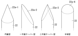
- FIG. 7 shows examples of shapes that the tapered tip of the needle may have.
- FIG. 8 shows an example of a method for manufacturing a dividing jig.
- FIG. 9 shows an example of a method for manufacturing a split jig.
- FIG. 10 is a perspective view showing an example of a dividing jig in which the protruding portion is formed of a plate.
- FIG. 11 is a view of the dividing jig of FIG. 10 as viewed from the u direction.
- FIG. 12 is a view of the dividing jig of FIG. 10 as viewed from the s direction.
- FIG. 13 shows an embodiment of a process for dividing a carbon fiber bundle into portions using a dividing jig having protruding portions formed with needles.
- FIG. 14 shows an embodiment of a process for dividing a carbon fiber bundle into portions using a dividing jig having protruding portions formed with needles.
- FIG. 15 shows an embodiment of a process for partially dividing a carbon fiber bundle using a dividing jig having protruding portions formed with needles.
- FIG. 16 shows an embodiment of a process for partially dividing a carbon fiber bundle using a dividing jig having protruding portions formed of plates.
- FIG. 17 shows an embodiment of a process for partially dividing a carbon fiber bundle using a dividing jig having protruding portions formed of plates.
- FIG. 18 is a plan view showing an example of a partially split carbon fiber bundle.
- FIG. 19 shows a situation that may occur if the position of the carbon fiber bundle in the y direction shifts while the protrusion of the dividing jig is not inserted.
- FIG. 20 shows a situation that may occur if the position of the carbon fiber bundle in the y direction shifts while the protrusion of the dividing jig is not inserted.
- FIG. 21 shows a situation that can occur if the position of the carbon fiber bundle in the y direction shifts while the protrusion of the dividing jig is not inserted.
- FIG. 22 is a perspective view showing an example of a slitter roll having a slit blade with a missing portion.
- FIG. 23 is a photograph showing the dividing jig after it has been used in the partial dividing process.
- FIG. 24 is a photograph showing the dividing jig after it has been used in the partial dividing process.
- FIG. 25 is a photograph showing the dividing jig after it has been used in the partial dividing process.
- FIG. 26 is a photograph showing the dividing jig after it has been used in the partial dividing process.
- Partial Splitting Line One embodiment of the present invention relates to a method for producing a partially split carbon fiber bundle.
- a partial dividing line 2 having a partial dividing section 1 is provided, for example as shown in FIG.
- an undivided carbon fiber bundle 3 as a starting material is unwound from a spool and supplied to a partial division section 1 .
- the bundle size of the carbon fiber bundle 3, i.e., the number of carbon fiber filaments constituting the carbon fiber bundle 3, is usually 12K or more, and may be 15K or more, 24 or more, 36K or more, 48K or more, etc., and is usually 120K or less, and may be 100K or less, 80K or less, 60K or less, etc., but is not limited thereto.
- K is a symbol meaning 1000, and for example, 12K means 12,000 and 120K means 120,000.
- the carbon fiber bundle 3 is subjected to a partial division process to become a partially divided carbon fiber bundle 4.
- the partial division process can be performed, for example, by intermittently piercing the carbon fiber bundle 3 running along the longitudinal direction (fiber direction) with a needle or a plate, but other tools may also be used.
- the partial division process of the carbon fiber bundles 3 in the partial division section can be performed by using a slitter roll having a slit blade provided on the circumferential surface thereof with a cutout portion.
- An example of such a slitter roll is shown in Fig. 22.
- a cutout portion 53 is provided in a slit blade 52 provided on a circumferential surface 51.
- the partially divided carbon fiber bundles 4 coming out of the partially divided section are wound up on another spool.
- the carbon fiber production line 5 includes, in order from the upstream side, a calcination section 7 in which precursor fiber bundles 6 made of polyacrylonitrile are calcined to form carbon fiber bundles, a surface treatment section 8 in which surface treatment is performed to introduce functional groups onto the carbon fiber surfaces, and a sizing section 9 in which the carbon fiber bundles are sized.
- the calcination section 7 usually includes a flameproofing section and a carbonization section as subsections, and may further include a graphitization section.
- the precursor fiber bundle 6 may be twisted, for example, at 5 to 20 turns/m.
- the unsplit carbon fiber bundle 3 is untwisted downstream of the baking section 7, preferably to an untwisted state. This untwisting is preferably performed before the completion of sizing, and in one example, may be performed upstream of the surface treatment section 8.
- the unsplit carbon fiber bundle 3 is produced in the carbon fiber production line 5, and then supplied to the partial division line 2 without being wound around a spool, and is partially divided in the partial division section 1 of the partial division line 2 to become a partially divided carbon fiber bundle 4.
- the partially divided carbon fiber bundle 4 is wound around a spool. Not winding the carbon fiber bundle produced in the carbon fiber production line onto a spool before dividing it into portions is advantageous in stabilizing the quality of the partially divided carbon fiber bundles, because the carbon fiber bundle does not develop a curl before being supplied to the partially dividing line, and therefore the posture of the carbon fiber bundle when it travels through the partially dividing section is stable.
- Carbon fiber bundles are prone to curling because they have plasticity, and more specifically, because a resin containing a low molecular weight compound called a sizing agent is used to bond the carbon fibers together. Therefore, even if the carbon fiber bundle is poured into a packaging container using the method disclosed in JP 2012-188773 A, for example, instead of being wound onto a spool, the shape of the carbon fiber bundle will become curled. In general, carbon fiber bundles that have been packaged even once before being supplied to the partial division line will become curled, making their posture unstable when they run through the partial division section.
- the posture of the carbon fiber bundle when it runs through the partial division section becomes particularly unstable when the carbon fiber bundle that is traverse wound around the spool is unwound and used, because in the traverse winding, the carbon fiber bundle is easily twisted locally when the moving direction of the traverse guide is reversed, and the twisted carbon fiber bundle does not completely return to its original state even after being unwound from the spool.
- the partial division process if the twisted portion of the carbon fiber bundle is processed with a tool such as a needle or plate, many carbon fibers will be cut, resulting in a problem that the carbon fiber bundle after partial division will be severely frayed.
- a carbon fiber bundle containing almost no twisted portions can be supplied to the partial division line, so that fluffing of the carbon fiber bundle in the partial division process is also suppressed.
- the carbon fiber bundles are sized before being fed to the partial division line. If the carbon fiber bundles are subjected to partial division processing without sizing, a large amount of fiber breakage will occur and the carbon fiber bundles will become significantly frayed. This is because the introduction of functional groups to the carbon fiber surface by surface treatment significantly increases the following two frictional forces.
- One of the two frictional forces is the frictional force acting between adjacent carbon fibers in the bundle, and the other is the frictional force acting between the carbon fibers and tools such as needles and plates used in the partial division processing.
- the reason why fraying associated with partial division processing is suppressed in sized carbon fiber bundles is that the sizing agent introduced into the carbon fiber bundle by sizing acts as a lubricant that reduces these frictional forces.
- the carbon fiber bundle is passed through a sizing bath and then dried. Since the carbon fibers are fixed to each other by sizing, it is desirable to apply high tension to the carbon fiber bundle in the sizing section 9 using a tensioning mechanism such as a dancer roll to sufficiently align the carbon fibers. On the other hand, it is desirable to apply high tension to the carbon fiber bundles 3 at the partial division line 2 as well so that a tool such as a needle or plate can reliably pierce the carbon fiber bundles 3 at the partial division section 1 .
- a single tensioning mechanism may be used as both the tensioning mechanism for the sizing section 9 and the tensioning mechanism for the partial division line 2.
- the force generated by the contraction of the precursor fiber bundle 6 due to the firing in the firing section 7 can also be used to apply tension to the carbon fiber bundles in the sizing section 9 and the partial division line 2.
- the carbon fiber bundle is divided into parts in the partial division section provided on the partial division line.
- the subdivision process is carried out by piercing a needle or plate into the carbon fiber bundle passing through the subdivision section.
- the carbon fiber bundles fed to the partial division section have a flat shape, and therefore have a width direction and a thickness direction in addition to a longitudinal direction (fiber direction).
- the width direction and the thickness direction are each perpendicular to the longitudinal direction and perpendicular to each other.
- a tension is applied to the carbon fiber bundle traveling through the partial division section so that the longitudinal direction is parallel to a first direction and the width direction is parallel to a second direction perpendicular to the first direction.
- the carbon fiber bundle passes through the partial division section in a state where it is stretched substantially straight along the first direction without being twisted and suspended in the air.
- the first direction is referred to as the x-direction in the sub-divided section
- the second direction is referred to as the y-direction in the sub-divided section, as shown in Figure 3.
- the direction perpendicular to both the x-direction and the y-direction is referred to as the z-direction.
- the x-direction may be perpendicular, inclined, or parallel to the direction of gravity.
- the y direction may also be perpendicular, inclined, or parallel to the direction of gravity.
- a splitting jig having a protrusion formed by a needle or a plate is installed in the partial splitting section.
- the carbon fiber bundles fed to the partial splitting line are intermittently pierced by the protrusion of the splitting jig when passing through the partial splitting section, thereby being split into portions.
- the number of protrusions that one splitting jig has is typically two or more, but may be one.
- the minimum number of protrusions that a splitting jig should have depends on how many sub-bundles the carbon fiber bundle should be partially divided into. How many sub-bundles the carbon fiber bundle should be partially divided into is naturally determined by the bundle size of the carbon fiber bundle that is the starting material, and the bundle size of the sub-bundles to be formed by partial division.
- FIGS. 4, 5 and 6 show an example of a dividing jig in which the protrusions are formed by needles.
- the dividing jig 20A shown in FIGS. 4, 5 and 6 has a base 21 and eight needles 22 fixed to the base 21.
- the eight needles are parallel to each other and extend along the u direction shown in the figure.
- the eight needles are also arranged at equal intervals along the t direction perpendicular to the u direction. All eight needles have the same length, and the straight lines connecting their tips are parallel to the t direction.
- a needle has at least a body, which is a part having a constant cross-sectional shape and area.
- the shape of the body is preferably a cylinder, but may be an elliptical cylinder, or may be a triangular prism, a square prism, a hexagonal prism, or any other prismatic prism.
- the cross-sectional shape of the elliptical cylinder may be an ellipse or an oval.
- the tip of the needle is preferably tapered so as to facilitate piercing the carbon fiber bundle.
- Examples of shapes that the tapered tip of a needle may have are shown in Figure 7. From the left, Figure 7 illustrates needles having a conical tip 22a-1, a uniplanar tapered tip 22a-2, a biplanar tapered tip 22a-3, and a hemispherical tip 22a-4.
- the diameter of the needle body is preferably 1 mm or less, more preferably 0.9 mm or less, and even more preferably 0.8 mm or less.
- the smaller the diameter of the body the easier it is to divide the carbon fiber bundle into sub-bundles of smaller bundle size. Therefore, it is preferable that the diameter of the body is smaller, but if it is too small, the rigidity decreases and the needle is likely to not penetrate the carbon fiber or to bend. Therefore, the diameter of the body is preferably 0.3 mm or more, more preferably 0.4 mm or more, and may be 0.5 mm or more. When the body is not cylindrical, the smallest width of the body is regarded as the diameter.
- the needle tip is hemispherical.
- the tip may be tapered other than hemispherical, with a rounded end or a terminal surface perpendicular to the axial direction.
- the dividing jig 20A shown in Figures 4, 5 and 6 can be manufactured by preparing a base 21 having a plurality of holes 21a formed therein, as shown in Figure 8, inserting the base of each needle 22 into each hole 21a, and then gluing and fixing the base 21 and the needles 22 together.
- the dividing jig 20A shown in Figures 4, 5 and 6 is merely one example of a dividing jig having multiple needles arranged in parallel to each other and fixed to each other. There is no limitation on the method for arranging multiple needles in parallel to each other and fixing them to each other to create a dividing jig.
- a needle 22 may be sandwiched between two plates 24 and fixed with a screw 25.
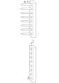
- the dividing jig 20B shown in FIGS. 10, 11 and 12 has seven spacers 31 and eight plates 32 arranged alternately and fixed to each other.
- the eight plates 32 have the same length, width, and thickness, and the shape of their main surfaces (surfaces perpendicular to the thickness direction) is rectangular.
- the eight plates 32 are parallel to each other, and the long sides of each main surface are parallel to the u direction shown in the figure.
- the eight plates are arranged at equal intervals along the t direction perpendicular to the u direction.
- the seven spacers 31 are stacked alternately with the eight plates 32 on the -u side of the dividing jig 20B.
- the +u side of each plate 32 protrudes relative to the spacers 31.
- the material of the plate 32 is typically a metal, preferably steel such as stainless steel, but is not limited thereto. There is no limitation on the method for fixing the spacer 31 and the plate 32 to each other, and for example, adhesive, clamping, screw fastening, or various other methods can be appropriately applied.
- the thickness of the plate is preferably 1 mm or less, and may be 0.9 mm or less, 0.8 mm or less, 0.7 mm or less, 0.6 mm or less, 0.5 mm or less, 0.4 mm or less, 0.3 mm or less, etc.
- the thinner the plate the easier it is to pierce the carbon fiber bundle and to divide the carbon fiber bundle into sub-bundles with smaller bundle sizes. From this viewpoint, it is preferable that the plate is thinner, but if it is too thin, the rigidity decreases and the plate is likely to not pierce the carbon fiber bundle or to bend. Therefore, the thickness of the plate is preferably 0.1 mm or more, more preferably 0.2 mm or more. When the plate is too thick to easily penetrate the carbon fiber bundles, the edge of the plate may be tapered.
- the dividing jig 20B shown in Figures 10, 11 and 12 shows one preferred embodiment, in which the plate 32 is rectangular, i.e., a square having four right-angled corners (90° interior corners), two of which are included in the protrusions.
- the plate 32 may be a polygon other than a square, such as a triangle, pentagon or hexagon, or may be a concave polygon, or may have no corners, such as an ellipse.
- the plate 32 is preferably polygonal, more preferably quadrangular, and particularly preferably rectangular.
- the partial dividing process of the carbon fiber bundle using the dividing jig is carried out as follows.
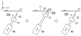
- the running direction of the carbon fiber bundle 11 is from left to right in the figures, and the same applies to Figures 16, 17, 19, 20, and 21 described below.
- the dividing jig 20A is linearly reciprocated by the actuator 40, so that the needles 22 intermittently pierce the traveling carbon fiber bundle 11.
- the dividing jig 20A is disposed so that its t direction is parallel to the y direction.
- the dividing jig 20A is swung about an axis 45 by an actuator (not shown), so that the needles 22 intermittently pierce the traveling carbon fiber bundle 11.
- the axis 45 is parallel to the y direction.
- the dividing jig 20A is positioned so that its t direction is parallel to the y direction, and when a cylinder is imagined centered on the axis 45, the longitudinal direction of the needle 22 is parallel to the radial direction of the cylinder.
- This example may be modified so that the splitting jig 20 rotates instead of swinging.
- the dividing jig 20 is swung about an axis 45 by an actuator (not shown), so that the needles 22 intermittently pierce the traveling carbon fiber bundle 11.
- the axis 45 is parallel to the y direction.
- the dividing jig 20A is positioned so that its t direction is parallel to the y direction, and when a cylinder is imagined centered on the axis 45, the longitudinal direction of the needle 22 is inclined relative to the radial direction of the cylinder.
- both the x direction and the y direction may be horizontal, in which case the carbon fiber bundle 11 may be pierced with the needle 22 from below or from above.
- the carbon fiber bundle 11 is divided by keeping the splitting jig 20A stationary for a certain period of time with the needles 22 piercing the traveling carbon fiber bundle 11.
- the needles 22 piercing the carbon fiber bundle 11 are not perpendicular to the traveling direction of the carbon fiber bundle 11, but are inclined so as to fall toward the downstream side (+x direction) of the traveling direction of the carbon fiber bundle 11 (angle ⁇ is smaller than 90°). This advantageously makes it difficult for carbon fiber waste to accumulate in the splitting jig 20.
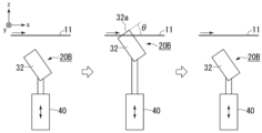
- Figs. 16 and 17 show examples in which a split jig having protruding portions formed of plates is used.
- the dividing jig 20B is linearly reciprocated by the actuator 40, so that the plate 32 intermittently pierces the traveling carbon fiber bundle 11.
- the dividing jig 20B is disposed so that its t direction is parallel to the y direction.
- the carbon fiber bundle 11 is divided by keeping the dividing jig 20B stationary for a certain period of time with the plate 32 piercing the traveling carbon fiber bundle 11.
- the dividing jig 20B is swung about an axis 45 by an actuator (not shown), so that the plate 32 intermittently pierces the traveling carbon fiber bundle 11.
- the axis 45 is parallel to the y direction.
- the splitting jig 20B is positioned so that its t direction is parallel to the y direction, and the carbon fiber bundle 11 is split by keeping the splitting jig 20B stationary for a certain period of time with the plate 32 piercing the running carbon fiber bundle 11.
- the same effect can be obtained by making the number of the multiple convex corners that are stuck into the carbon fiber bundle during the partial dividing process not exceed 1.
- the number of convex corners of the plate-shaped protruding portion may be only one.
- the inner angle of the convex corner that pierces the carbon fiber bundle is set to 90° or more, so that the above effect becomes more remarkable. From the viewpoint of making it easier for the protrusion to pierce the carbon fiber bundle, the inner angle is preferably 120° or less.
- the motion of the dividing jig is preferably a reciprocating motion rather than a rotational motion.
- reciprocating motion include linear reciprocating motion and swinging motion.
- Reciprocating motion is preferred because it prevents winding when a problem occurs in which the carbon fiber bundle (all or some of the sub-bundles) breaks. If winding occurs, the production line must be stopped and recovery will take a long time.
- a suitable example of an actuator for reciprocating the dividing jig is an air cylinder, but is not limited thereto, and may be an electric motor.
- the dividing jig is swung so that when the protrusion is inserted into the carbon fiber bundle, it moves in the opposite direction to the running direction of the carbon fiber bundle, and when the protrusion is removed from the carbon fiber bundle, it moves in the same direction as the running direction of the carbon fiber bundle. This makes it less likely that a protrusion that has been inserted into the carbon fiber bundle will not come out, or that when the protrusion is removed from the carbon fiber bundle, the carbon fiber bundle will be pulled by the protrusion and vibrate significantly, resulting in poor insertion of the protrusion.
- the carbon fiber bundle travels with the protruding portion of the dividing jig stuck therein, so that slits are formed in the carbon fiber bundle.
- the formation of the slits is interrupted.
- a partially divided carbon fiber bundle in which the carbon fiber bundle is partially divided into a plurality of sub-bundles is obtained.
- a partially divided carbon fiber bundle in which the divided portions into five sub-bundles are intermittently formed along the longitudinal direction is shown in Fig. 18.
- Fig. 18 is a plan view of the partially divided carbon fiber bundle 4 as viewed from the thickness direction.
- the partially divided carbon fiber bundle 4 has four slit rows formed therein, namely, a first slit row R S1 , a second slit row R S2 , a third slit row R S3 and a fourth slit row R S4 .
- the first slit row R S1 is composed of a plurality of first slits S1 arranged along the longitudinal direction of the partially split carbon fiber bundle 4.
- the second slit row R S2 is composed of a plurality of second slits S2 arranged along the longitudinal direction of the partially split carbon fiber bundle 4.
- the third slit row R S3 is composed of a plurality of third slits S3 arranged along the longitudinal direction of the partially split carbon fiber bundle 4.
- the fourth slit row R S4 is composed of a plurality of fourth slits S4 arranged along the longitudinal direction of the partially split carbon fiber bundle 4.
- the slit length Ls which is the length of the first to fourth slits S1, S2, S3, S4, is approximately the product of the time from when the protruding portion is pierced into the carbon fiber bundle until it is pulled out and the running speed of the carbon fiber bundle.
- the slit gap length L G which is the length of the slit gap G S in each of the first to fourth slit rows R S1 , R S2 , R S3 , R S3 , is approximately the product of the time from when the protruding portion is pulled out of the carbon fiber bundle until it next pierces the carbon fiber bundle and the running speed of the carbon fiber bundle. Since the motion period of the dividing jig is constant, the slit length L S and the inter-slit gap length L G are constant within any slit row and are common to all slit rows.
- the slit length Ls is preferably 20 cm or more, more preferably 40 cm or more, and even more preferably 60 cm or more.
- the longer the slit length Ls the more advantageous it is because the chopped carbon fiber bundle obtained when cutting the split carbon fiber bundle 4 to produce the SMC contains more bundles of the same size as the sub-bundles.
- the fiber length of the chopped carbon fiber bundle is preferably 5 to 60 mm, more preferably 10 to 30 mm, and can even be 20 mm or less. From this perspective, there is no particular upper limit to the slit length Ls.
- the slit length Ls is preferably 300 cm or less, more preferably 200 cm or less, and even more preferably 150 cm or less.
- the slit length Ls can be set, for example, to 60 cm or more and less than 100 cm, 100 cm or more and less than 150 cm, 150 cm or more and less than 200 cm, 200 cm or more and less than 250 cm, or 250 cm or more and less than 300 cm.
- the inter-slit gap length L G is preferably 1 cm or less, more preferably 5 mm or less, further preferably 2 mm or less, and may be 1 mm or less.
- the above description of the slit length L.sub.2 and the slit gap length L.sub.2 is not limited to the partially divided carbon fiber bundle partially divided into five sub-bundles, but also applies to the partially divided carbon fiber bundle partially divided into four or less or six or more sub-bundles.
- the bundle size of the sub-bundles formed by the partial division process is not particularly limited.
- the bundle size of the sub-bundles is preferably set to 6K or less, more preferably 4K or less, even more preferably 3K or less, and even more preferably 2K or less.
- the size of the sub-bundles when partially dividing a carbon fiber bundle having a bundle size of 36K to 120K is preferably set to 18K or less, and may be, for example, 15K or less, 12K or less, 9K or less, 6K or less, 4K or less, 3K or less, 2K or less, etc.
- the bundle size of the sub-bundle is preferably 0.5K or more, and more preferably 1K or more.
- n is an integer of 2 or more
- the dividing jig must have at least (n-1) protrusions.
- the dividing jig must be arranged in the partial division section so that the (n-1) protrusions can be inserted into the carbon fiber bundle simultaneously.
- a grooved guide roller with a groove width that matches the width of the carbon fiber bundle can be used.
- the idea can be changed so that, instead of dividing the carbon fiber bundle into n sub-bundles using a dividing jig with exactly (n-1) protrusions, the number of protrusions on the dividing jig can be (n+1) or more, so that the carbon fiber bundle is divided into at least n sub-bundles.
- a certain degree of variation in the y-direction position of the carbon fiber bundle within the partial division section is tolerated so that the running speed of the carbon fiber bundle does not need to be reduced, and even if there is a variation in the y-direction position, the number of protrusions that simultaneously pierce the carbon fiber bundle does not fall below (n-1).
- n 9 and the dividing jig has (n+1) or 10 needles as protrusions.
- the y-direction position of the carbon fiber bundle 11 shifts slightly, so that the number of protrusions that will next be stuck into the carbon fiber bundle 11 is nine.
- the number of sub-bundles increases from nine to ten, but no sub-bundles with abnormally large bundle sizes are formed.
- the position of the carbon fiber bundle 11 in the y direction is significantly shifted after the eight protrusions (needles 22) of the dividing jig 20A that have been stuck into the carbon fiber bundle 11 are pulled out, and therefore the number of protrusions that will next be stuck into the carbon fiber bundle 11 remains at 8. In this case as well, no sub-bundles with abnormally large bundle sizes are formed.
- the longitudinal direction of the needle 22 is parallel to the z direction when the needle 22 is inserted into the carbon fiber bundle 11, but this is not limited to this.
- the needle 22 may be inclined so as to fall toward the downstream side in the running direction of the carbon fiber bundle 11 when the needle 22 is inserted into the carbon fiber bundle 11.
- the number of protrusions of the splitting jig that simultaneously penetrate the carbon fiber bundle is set so that the bundle size of the sub-bundles formed is equal to or less than a predetermined upper limit. Therefore, if the bundle size of the carbon fiber bundle before splitting is 15K and the upper limit of the bundle size of the sub-bundles is approximately 5K, the number of protrusions of the splitting jig that simultaneously penetrate can be set to 2 or 3. If the bundle size of the carbon fiber bundle before splitting is 50K and the upper limit of the bundle size of the sub-bundles is approximately 10K, the number of protrusions of the splitting jig that simultaneously penetrate can be set to 4 or 5.
- the carbon fiber bundles supplied to the partial division section may have fiber waste attached thereto, which is generated when a small portion of the carbon fibers is cut in an upstream process.
- the partial division process in the partial division section may also cut the carbon fibers, generating fiber waste.
- Such fiber waste is likely to get caught on the protruding portion of the division jig. If this fiber waste accumulates and becomes large cotton waste and adheres to the partial carbon fiber bundles, it may deteriorate the quality of the SMC manufactured using the partial carbon fiber bundles. Therefore, in a preferred embodiment, compressed air may be blown onto the protruding portion of the dividing jig during the partial dividing process to blow off the caught fiber waste and/or cotton dust. The compressed air may be blown continuously or intermittently. More preferably, a suction nozzle is provided near the dividing jig to remove the fiber waste and/or cotton dust blown off by the compressed air, thereby preventing them from adhering to the partially divided carbon fiber bundles.
- Embodiment A1 A method for producing a partially split carbon fiber bundle, in which carbon fiber bundles are continuously supplied from a carbon fiber production line to a partial splitting line connected to the carbon fiber production line, and are subjected to a partial splitting process in a partial splitting section provided in the partial splitting line.
- Emodiment A2 The method according to embodiment A1, wherein the carbon fiber production line includes a sizing section, and the carbon fiber bundle is sized in the sizing section before being supplied to the portion division line.
- Emodiment A3 A method according to embodiment A2, in which a single tensioning mechanism serves as both the tensioning mechanism for the sizing section and the tensioning mechanism for the partial dividing line.
- Emodiment A4 A method according to any one of embodiments A1 to A3, in which a force generated due to the contraction of a precursor fiber bundle in the carbon fiber production line is utilized to apply tension to the carbon fiber bundle in the partial division line.
- the partial splitting process includes intermittently piercing the carbon fiber bundle running along its longitudinal direction with a protrusion of a splitting jig having a protrusion.
- Embodiment A17 A method according to embodiment A15 or A16, in which the partial division section has an x direction, a y direction, and a z direction that are perpendicular to each other, and when the longitudinal direction and width direction of the carbon fiber bundle as it passes through the partial division section are parallel to the x direction and the y direction, respectively, the division jig oscillates around an axis parallel to the y direction.
- a slit row consisting of a plurality of slits lined up along the longitudinal direction of the carbon fiber bundle is formed in the carbon fiber bundle, and the length of the plurality of slits is 20 cm or more, preferably 40 cm or more, and more preferably 60 cm or more.
- the length may be 60 cm or more and less than 100 cm, 100 cm or more and less than 150 cm, 150 cm or more and less than 200 cm, 200 cm or more and less than 250 cm, or 250 cm or more and less than 300 cm.
- Embodiment B1 A method for producing partially divided carbon fiber bundles by subjecting a carbon fiber bundle to a partial dividing process, the partial dividing process including intermittently piercing the carbon fiber bundle traveling along its own longitudinal direction with a protrusion of a dividing jig having a protrusion, the protrusion being formed by a needle, and the needle being inclined so as to fall downstream in the traveling direction of the carbon fiber bundle when pierced into the carbon fiber bundle.
- Embodiment B2 A method for producing partially divided carbon fiber bundles by subjecting a carbon fiber bundle to a partial dividing process, the partial dividing process including intermittently piercing a protrusion of a dividing jig having a protrusion into the carbon fiber bundle running along its longitudinal direction, the protrusion being formed of a plate, and when the plate-shaped protrusion is inserted into the carbon fiber bundle, in the portion of the protrusion inserted into the carbon fiber bundle, an edge of the protrusion facing the upstream side in the running direction of the carbon fiber bundle is inclined so as to fall toward the downstream side in the running direction of the carbon fiber bundle.
- Emodiment B3 A method according to embodiment B2, in which the plate-shaped protrusion has at least one convex corner, and in the partial division process, the number of the convex corners of the protrusion that are stuck into the carbon fiber bundle does not exceed one.
- Emodiment B4 A method according to embodiment B2 or B3, in which the plate-shaped protrusion has at least one convex corner with an interior angle of 90° or more but does not have any convex corners with an interior angle of less than 90°, and in which, in the partial division process, the number of the convex corners with an interior angle of 90° or more that are in a state of being stuck into the carbon fiber bundle does not exceed one.
- Emodiment B5 A method according to any one of embodiments B2 to B4, in which the plate-shaped protrusion has two right-angled corners at the protruding end, and in the partial division process, only one of the two right-angled corners of the protrusion is pierced into the carbon fiber bundle.
- Emodiment B6 A method according to any one of embodiments B2 to B5, in which the protrusion is formed using a rectangular plate, and in the partial division process, only one of the four right-angled corners of the rectangular plate penetrates the carbon fiber bundle.
- Embodiment B7 A method for producing partially divided carbon fiber bundles by subjecting a carbon fiber bundle to a partial division process, the partial division process comprising intermittently piercing the carbon fiber bundle running along its longitudinal direction with a protrusion of a division jig having a protrusion, the protrusion being formed of a plate, the plate-shaped protrusion having at least one convex corner with an interior angle of 90° or more but no convex corner with an interior angle of less than 90°, and in the partial division process, the number of the convex corners with an interior angle of 90° or more that are in a state of being pierced into the carbon fiber bundle does not exceed 1.
- Emodiment B8 A method for producing partially divided carbon fiber bundles by subjecting a carbon fiber bundle to a partial division process, the partial division process including intermittently piercing the carbon fiber bundle running along its longitudinal direction with a protrusion of a division jig having a protrusion, the protrusion being formed of a plate, the plate-shaped protrusion having two right-angled corners, and in the partial division process, only one of the two right-angled corners is pierced into the carbon fiber bundle.
- Emodiment B9 A method for producing partially divided carbon fiber bundles by subjecting a carbon fiber bundle to a partial division process, the partial division process including intermittently piercing the carbon fiber bundle running along its longitudinal direction with a protrusion of a division jig having a protrusion, the protrusion being formed using a rectangular plate, and in the partial division process, only one of four right-angled corners of the rectangular plate is pierced into the carbon fiber bundle.
- the dividing jig is reciprocated to intermittently pierce the carbon fiber bundle with the protrusions in the partial dividing process.
- the reciprocating motion may be a linear reciprocating motion or a swinging motion.
- the protrusion moves in the opposite direction to the running direction of the carbon fiber bundle, and when the protrusion comes out of the carbon fiber bundle, the protrusion moves in the same direction as the running direction of the carbon fiber bundle.
- Embodiment B13 A method according to embodiment B11 or B12, in which the space in which the partial division process is performed has an x-direction, a y-direction, and a z-direction which are perpendicular to each other, and the longitudinal direction and width direction of the carbon fiber bundle when passing through the space are parallel to the x-direction and the y-direction, respectively, and the division jig oscillates around an axis parallel to the y-direction.
- Emodiment B17 A method according to embodiment B15 or B16, wherein the bundle size of each of the sub-bundles is 18K or less, preferably 15K or less, more preferably 12K or less, even more preferably 9K or less, and may be 6K or less, 4K or less, 3K or less or 2K or less.
- a slit row consisting of a plurality of slits lined up along the longitudinal direction of the carbon fiber bundle is formed in the carbon fiber bundle, and the length of the plurality of slits is 20 cm or more, preferably 40 cm or more, and more preferably 60 cm or more.
- the length may be 60 cm or more and less than 100 cm, 100 cm or more and less than 150 cm, 150 cm or more and less than 200 cm, 200 cm or more and less than 250 cm, or 250 cm or more and less than 300 cm.
- Emodiment C1 A method for producing partially divided carbon fiber bundles by subjecting a carbon fiber bundle to a partial division process, the partial division process including swinging a division jig having a protrusion to intermittently pierce the protrusion into the carbon fiber bundle traveling along its own longitudinal direction.
- Emodiment C2 A method according to embodiment C1, wherein when the protrusion penetrates the carbon fiber bundle, the protrusion moves in the opposite direction to the running direction of the carbon fiber bundle, and when the protrusion comes out of the carbon fiber bundle, the protrusion moves in the same direction as the running direction of the carbon fiber bundle.
- Emodiment C3 A method according to embodiment C1 or C2, in which the space in which the partial division process is performed has an x-direction, a y-direction, and a z-direction which are perpendicular to each other, and the longitudinal direction and width direction of the carbon fiber bundle when passing through the space are parallel to the x-direction and the y-direction, respectively, and the division jig oscillates around an axis parallel to the y-direction.
- the protrusions are formed with needles.
- Emodiment D1 A method for producing partially divided carbon fiber bundles by subjecting a carbon fiber bundle to a partial division process, the partial division process including intermittently piercing the carbon fiber bundle running along its own longitudinal direction with a protrusion of a dividing jig having a protrusion, and blowing compressed air onto the protrusion of the dividing jig while the partial division process is being performed.
- the protrusion is formed by a needle.
- Emodiment D3 The method according to embodiment D1, wherein the protrusion is formed of a plate.
- Emodiment D6 A method according to embodiment D4 or D5, wherein the bundle size of each of the sub-bundles is 18K or less, preferably 15K or less, more preferably 12K or less, even more preferably 9K or less, and may be 6K or less, 4K or less, 3K or less or 2K or less.
- Emodiment D7 The method according to any of embodiments D1 to D3, wherein the partial splitting process splits the carbon fiber bundle partially into a plurality of sub-bundles, and the bundle size of each of the plurality of sub-bundles is 18K or less, preferably 15K or less, more preferably 12K or less, even more preferably 9K or less, and may be 6K or less, 4K or less, 3K or less, or 2K or less.
- Emodiment D8 The method according to any one of embodiments D1 to D7, in which, in the partial division treatment, a slit row consisting of a plurality of slits lined up along the longitudinal direction of the carbon fiber bundle is formed in the carbon fiber bundle, and the length of the plurality of slits is 20 cm or more, preferably 40 cm or more, and more preferably 60 cm or more, and may be, for example, 60 cm or more and less than 100 cm, 100 cm or more and less than 150 cm, 150 cm or more and less than 200 cm, 200 cm or more and less than 250 cm, or 250 cm or more and less than 300 cm.
- Emodiment E1 A method for producing a partially divided carbon fiber bundle by subjecting a carbon fiber bundle to a partial division process, the partial division process comprising intermittently piercing the carbon fiber bundle running along its own longitudinal direction with a protruding portion of a division jig having a protruding portion, the division jig having (n+1) or more protruding portions, and the carbon fiber bundle is partially divided into n or (n+1) sub-bundles in the partial division process, where n is an integer of 2 or more.
- Emodiment E2 A method according to embodiment E1, wherein the bundle size of each of the sub-bundles is 18K or less, preferably 15K or less, more preferably 12K or less, even more preferably 9K or less, and may be 6K or less, 4K or less, 3K or less or 2K or less.
- the protrusion is formed by a needle.
- the protrusion is formed of a plate.
- a slit row consisting of a plurality of slits lined up along the longitudinal direction of the carbon fiber bundle is formed in the carbon fiber bundle, and the length of the plurality of slits is 20 cm or more, preferably 40 cm or more, and more preferably 60 cm or more.
- the length may be 60 cm or more and less than 100 cm, 100 cm or more and less than 150 cm, 150 cm or more and less than 200 cm, 200 cm or more and less than 250 cm, or 250 cm or more and less than 300 cm.
- a dividing jig having a plurality of needles arranged parallel to each other and fixed to each other as exemplified in Figures 4 to 6 (the same as the dividing jig used in Experiment 3 described later) was installed in the partial division section as a means for partial division treatment.
- the needles were intermittently pierced into the carbon fiber bundle by swinging the dividing jig around a swing axis provided parallel to the width direction of the carbon fiber bundle traveling in the partial division section.
- Experiment 3 A partial division line as shown in FIG. 1 was prepared, and a carbon fiber bundle (TR50S15L, manufactured by Mitsubishi Chemical Co., Ltd.) having 15K filaments, which was produced in a carbon fiber production line (including a sizing section) separate from the partial division line and wound around a bobbin, was pulled out from the bobbin and an attempt was made to perform partial division processing.
- a dividing jig having multiple protrusions each formed by a needle was installed as a means for dividing the specimen into portions.
- the needle was made of stainless steel (SUS304), had a hemispherical tip, and had a cylindrical body with a diameter of 0.8 mm.
- the dividing jig In the dividing jig, more than 15 needles were arranged in parallel at a constant pitch of 1 mm, as in the examples shown in Figures 4 to 6. In the partially divided section, the orientation of the dividing jig was adjusted so that the straight line connecting the tips of the needles was parallel to the width direction of the traveling carbon fiber bundle. Since the width of the undivided carbon fiber bundle was approximately 7 mm, the number of needles that could be inserted into the carbon fiber bundle at the same time was approximately six.
- the splitting jig was held still for 4.2 seconds with the needle piercing the carbon fiber bundle, and within the next 0.2 seconds, the needle was removed from the carbon fiber bundle, and the splitting jig was moved back and forth linearly so as to pierce the carbon fiber bundle again. This operation was repeated.
- the direction of the reciprocating movement of the dividing jig was perpendicular to both the running direction and the width direction of the carbon fiber bundle, i.e., the dividing jig was moved parallel to the z direction in FIG.
- the angle ( ⁇ in the example of FIG. 14 ) between the longitudinal direction of the needle and the running direction of the carbon fiber bundle was set to 45°. That is, during the rest period, the needle was inclined so as to fall at an angle of 45° downstream in the running direction of the carbon fiber bundle.
- partial division of the carbon fiber bundle was attempted in the same manner as in Experiment 3, and there was no problem with the stability of the partial division process.
- the amount of carbon fiber scraps accumulated in the dividing jig by the partial division process for the same period of time was less than that in Experiment 3, as shown in FIG.
- Experiment 5 A fiber-splitting jig was set up in the same manner as in Experiment 4, and while the carbon fiber bundle was being run, the fiber-splitting jig was stationary with a needle pierced into the carbon fiber bundle. When the jig was rotated so that the needle moved in the opposite direction to the running direction of the carbon fiber bundle, it was investigated whether the needle would come out of the carbon fiber bundle. As a result, when the dividing jig was rotated, the carbon fiber bundle was bitten into the dividing jig, and the needle could not be removed from the carbon fiber bundle. This is thought to be because the rotation of the dividing jig caused the needle that had pierced the carbon fiber bundle to tilt toward the upstream side in the running direction of the carbon fiber bundle.
- the orientation of the splitting jig was adjusted so that the straight lines connecting the corners of different rectangular plates were parallel to the width direction of the traveling carbon fiber bundle, and the position of the splitting jig during the stationary period of 4.2 seconds was adjusted so that only one corner of each rectangular plate was pierced into the carbon fiber bundle. Since the width of the unsplit carbon fiber bundle was about 7 mm, the number of rectangular plates that could be pierced into the carbon fiber bundle at the same time was approximately eight.
- the angle ( ⁇ in the example of FIG. 16 ) made by the edge of the rectangular plate facing the upstream side of the running direction of the carbon fiber bundle at the part where the rectangular plate pierced the carbon fiber bundle and the running direction was set to three different angles of 30°, 45°, and 60°.
- the results showed that there was no problem with the stability of the partial division process.
- the larger the angle the larger the amount of carbon fiber scraps accumulated in the division jig by the partial division process for the same time.
- Figure 25 is a photograph of the division jig after the partial division process was performed with the angle set to 60°
- Figure 26 is a photograph of the division jig after the partial division process was performed for the same period of time with the angle set to 30°.
- the present invention provides an improved method for producing partially split carbon fiber bundles.
Landscapes
- Engineering & Computer Science (AREA)
- Textile Engineering (AREA)
- Mechanical Engineering (AREA)
- Inorganic Fibers (AREA)
Abstract
The main purpose of the present invention is to provide an improvement to a method for producing a partially divided carbon fiber bundle. According to the method for producing a partially divided carbon fiber bundle, a carbon fiber bundle is supplied continuously from a carbon fiber production line to a partial division line connected to the carbon fiber production line, and is subjected to partial division processing in a division section provided in the partial division line. The partial division processing may include stabbing a protruding portion of a dividing jig intermittently into the carbon fiber bundle running along the longitudinal direction thereof. The protruding portion may be a needle.
Description
本発明は、主として、部分分割炭素繊維束(partially split carbon fiber bundle)を製造する方法に関する。
本願は、2022年10月28日に日本国特許庁に出願された、特願2022-173173号、及び2023年7月24日に日本国特許庁に出願された、特願2023-120315号に基づき優先権を主張し、その内容をここに援用する。 The present invention relates primarily to a method for producing a partially split carbon fiber bundle.
This application claims priority based on Japanese Patent Application No. 2022-173173 filed with the Japan Patent Office on October 28, 2022, and Japanese Patent Application No. 2023-120315 filed with the Japan Patent Office on July 24, 2023, the contents of which are incorporated herein by reference.
SMC(シートモールディングコンパウンド)のような、チョップド炭素繊維束からなるランダムマット型の補強材が樹脂で含浸されたプリプレグを硬化させて得られるCFRPの機械特性は、チョップド炭素繊維束の束サイズ、つまり、束を構成する炭素繊維フィラメントの数の影響を受ける。束サイズのより小さなチョップド炭素繊維束を補強材に用いたSMCは、より機械特性の良好なCFRPを与え得る(特許文献1)。
The mechanical properties of CFRP obtained by curing a prepreg in which a random mat type reinforcing material made of chopped carbon fiber bundles, such as SMC (sheet molding compound), is impregnated with resin, are affected by the bundle size of the chopped carbon fiber bundles, i.e., the number of carbon fiber filaments that make up the bundle. SMC using chopped carbon fiber bundles with smaller bundle size as reinforcing material can give CFRP with better mechanical properties (Patent Document 1).
一方で、炭素繊維束はその束サイズが大きい程、生産コストが低くなる。そのため、プレートや針を間欠的に突き刺すことによって炭素繊維束を部分分割(partial-split)してから、SMCの製造に用いることが提案されている(特許文献2)。
部分分割とは、元の1本の連続繊維束を、部分的に複数のサブ束に分割することをいう。 On the other hand, the larger the carbon fiber bundle, the lower the production cost, so it has been proposed to partially split the carbon fiber bundle by intermittently piercing it with a plate or needle before using it to manufacture SMC (Patent Document 2).
The term "partial division" refers to partially dividing an original continuous fiber bundle into a plurality of sub-bundles.
本発明の目的は、部分分割炭素繊維束を製造する方法における改良を提供することである。より具体的には、本発明の目的には以下が含まれる。
・品質の安定した部分分割炭素繊維束を製造する技法を提供すること。
・SMCの原材料として適した部分分割炭素繊維束を提供すること。
・部分分割処理中のトラブルに起因する部分分割炭素繊維束の品質低下を防止すること。
・部分分割処理中のトラブルに起因する部分分割炭素繊維束の製造効率低下を防止すること。 It is an object of the present invention to provide an improvement in a method for producing partially split carbon fiber bundles. More specifically, the objects of the present invention include the following:
- To provide a technique for producing partially split carbon fiber bundles with stable quality.
- To provide partially split carbon fiber bundles suitable as raw materials for SMC.
- Prevent deterioration in the quality of the partially divided carbon fiber bundles due to problems during the partial division process.
Preventing a decrease in the production efficiency of partially divided carbon fiber bundles due to problems during the partial division process.
本発明の一態様によれば、部分分割炭素繊維束を製造する方法であって、炭素繊維束が炭素繊維製造ラインから前記炭素繊維製造ラインに連結された部分分割ラインに連続的に供給され、前記部分分割ラインに設けられた部分分割セクションにおいて部分分割処理される、方法が提供される。
According to one aspect of the present invention, there is provided a method for producing partially split carbon fiber bundles, in which carbon fiber bundles are continuously supplied from a carbon fiber production line to a partial splitting line connected to the carbon fiber production line, and are subjected to a partial splitting process in a partial splitting section provided in the partial splitting line.
本発明の他の一態様によれば、炭素繊維束を部分分割処理して部分分割炭素繊維束を製造する方法であって、前記部分分割処理は自身の長手方向に沿って走行する前記炭素繊維束に、突出部を有する分割ジグの前記突出部を間欠的に突き刺すことを含み、前記突出部は針で形成され、前記針は前記炭素繊維束に突き刺さっているときに前記炭素繊維束の走行方向下流側に倒れるように傾斜している、方法が提供される。
According to another aspect of the present invention, there is provided a method for manufacturing partially divided carbon fiber bundles by subjecting a carbon fiber bundle to a partial division process, the partial division process including intermittently piercing the carbon fiber bundle traveling along its own longitudinal direction with a protrusion of a division jig having a protrusion, the protrusion being formed by a needle, and the needle being inclined so as to fall downstream in the traveling direction of the carbon fiber bundle when pierced into the carbon fiber bundle.
本発明の更に他の一態様によれば、炭素繊維束を部分分割処理して部分分割炭素繊維束を製造する方法であって、前記部分分割処理は自身の長手方向に沿って走行する前記炭素繊維束に、突出部を有する分割ジグの前記突出部を間欠的に突き刺すことを含み、前記突出部はプレートで形成され、前記プレートが前記炭素繊維束に突き刺さっているときに、前記プレートが前記炭素繊維束に突き刺さった部分においては、前記炭素繊維束の走行方向上流側に臨む前記プレートの縁が前記炭素繊維束の走行方向下流側に倒れるように傾斜している、方法が提供される。
According to yet another aspect of the present invention, there is provided a method for manufacturing partially divided carbon fiber bundles by subjecting a carbon fiber bundle to a partial division process, the partial division process including intermittently piercing the carbon fiber bundle traveling along its own longitudinal direction with a protrusion of a division jig having a protrusion, the protrusion being formed of a plate, and when the plate is pierced into the carbon fiber bundle, the edge of the plate facing the upstream side in the running direction of the carbon fiber bundle is inclined so as to fall toward the downstream side in the running direction of the carbon fiber bundle in the portion where the plate is pierced into the carbon fiber bundle.
本発明の更に他の一態様によれば、炭素繊維束を部分分割処理して部分分割炭素繊維束を製造する方法であって、前記部分分割処理は自身の長手方向に沿って走行する前記炭素繊維束に、突出部を有する分割ジグの前記突出部を間欠的に突き刺すことを含み、前記突出部はプレートで形成され、プレート型の前記突出部が内角90°以上の凸コーナーを少なくとも1つ有するが内角90°未満の凸コーナーを有さず、前記部分分割処理においては前記突出部が有する前記内角90°以上の凸コーナーのうち前記炭素繊維束に突き刺さった状態にあるものの数が1を超えない、方法が提供される。
According to yet another aspect of the present invention, there is provided a method for manufacturing partially divided carbon fiber bundles by subjecting a carbon fiber bundle to a partial division process, the partial division process including intermittently piercing the carbon fiber bundle traveling along its longitudinal direction with a protrusion of a division jig having a protrusion, the protrusion being formed of a plate, the plate-shaped protrusion having at least one convex corner with an interior angle of 90° or more but no convex corners with an interior angle of less than 90°, and the number of the convex corners of the protrusion with an interior angle of 90° or more that are pierced into the carbon fiber bundle does not exceed one in the partial division process.
本発明の更に他の一態様によれば、炭素繊維束を部分分割処理して部分分割炭素繊維束を製造する方法であって、前記部分分割処理は自身の長手方向に沿って走行する前記炭素繊維束に、突出部を有する分割ジグの前記突出部を間欠的に突き刺すことを含み、前記突出部はプレートで形成され、プレート型の前記突出部は2つの直角コーナーを有し、前記部分分割処理では前記2つの直角コーナーの片方だけが前記炭素繊維束に突き刺さる、方法が提供される。
According to yet another aspect of the present invention, there is provided a method for manufacturing a partially divided carbon fiber bundle by subjecting a carbon fiber bundle to a partial division process, the partial division process including intermittently piercing the carbon fiber bundle running along its longitudinal direction with a protrusion of a division jig having a protrusion, the protrusion being formed of a plate, the plate-shaped protrusion having two right-angled corners, and only one of the two right-angled corners being pierced into the carbon fiber bundle in the partial division process.
本発明の更に他の一態様によれば、炭素繊維束を部分分割処理して部分分割炭素繊維束を製造する方法であって、前記部分分割処理は自身の長手方向に沿って走行する前記炭素繊維束に、突出部を有する分割ジグの前記突出部を間欠的に突き刺すことを含み、前記突出部は矩形プレートを用いて形成され、前記部分分割処理では前記矩形プレートが有する4つの直角コーナーの1つだけが前記炭素繊維束に突き刺さる、方法が提供される。
According to yet another aspect of the present invention, there is provided a method for manufacturing a partially divided carbon fiber bundle by subjecting a carbon fiber bundle to a partial division process, the partial division process including intermittently piercing the carbon fiber bundle running along its longitudinal direction with a protrusion of a division jig having a protrusion, the protrusion being formed using a rectangular plate, and in the partial division process, only one of the four right-angled corners of the rectangular plate is pierced into the carbon fiber bundle.
本発明の更に他の一態様によれば、炭素繊維束を部分分割処理して部分分割炭素繊維束を製造する方法であって、前記部分分割処理は、突出部を有する分割ジグを揺動させて、自身の長手方向に沿って走行する前記炭素繊維束に前記突出部を間欠的に突き刺すことを含む、方法が提供される。
According to yet another aspect of the present invention, there is provided a method for manufacturing a partially divided carbon fiber bundle by subjecting a carbon fiber bundle to a partial division process, the partial division process including swinging a division jig having a protrusion to intermittently pierce the protrusion into the carbon fiber bundle traveling along its own longitudinal direction.
本発明の更に他の一態様によれば、炭素繊維束を部分分割処理して部分分割炭素繊維束を製造する方法であって、前記部分分割処理は自身の長手方向に沿って走行する前記炭素繊維束に、突出部を有する分割ジグの前記突出部を間欠的に突き刺すことを含み、前記部分分割処理が行われているときに前記分割ジグの前記突出部に圧縮空気を吹き付ける、方法が提供される。
According to yet another aspect of the present invention, there is provided a method for manufacturing a partially divided carbon fiber bundle by subjecting a carbon fiber bundle to a partial division process, the partial division process including intermittently piercing the carbon fiber bundle traveling along its own longitudinal direction with a protrusion of a division jig having a protrusion, and blowing compressed air onto the protrusion of the division jig while the partial division process is being performed.
本発明の更に他の一態様によれば、炭素繊維束を部分分割処理して部分分割炭素繊維束を製造する方法であって、前記部分分割処理は自身の長手方向に沿って走行する前記炭素繊維束に、突出部を有する分割ジグの前記突出部を間欠的に突き刺すことを含み、前記分割ジグが(n+1)個以上の前記突出部を有し、前記部分分割処理では前記炭素繊維束が部分的にn本または(n+1)本のサブ束に分割される、方法が提供される。ただし、nは2以上の整数である。
According to yet another aspect of the present invention, there is provided a method for manufacturing a partially divided carbon fiber bundle by subjecting a carbon fiber bundle to a partial division process, the partial division process including intermittently piercing the carbon fiber bundle running along its longitudinal direction with a protrusion of a division jig having a protrusion, the division jig having (n+1) or more protrusions, and the carbon fiber bundle being partially divided into n or (n+1) sub-bundles in the partial division process. Here, n is an integer of 2 or more.
本発明によれば、部分分割炭素繊維束を製造する方法における改良が提供される。
The present invention provides an improvement in the method for producing partially split carbon fiber bundles.
以下、本発明の実施形態について適宜図面を参照しながら説明する。図面における寸法比は、説明の便宜上のものであり、実際のものとは異なる場合がある。また、図面において、同一の構成については同じ符号を用いて示し、重複する構成について説明を省略することがある。
Below, an embodiment of the present invention will be described with reference to the drawings as appropriate. The dimensional ratios in the drawings are for the convenience of explanation and may differ from the actual ones. In addition, in the drawings, the same components are indicated by the same reference numerals, and descriptions of overlapping components may be omitted.
1.部分分割ライン
本発明の一実施形態は、部分分割炭素繊維束を製造する方法に関する。
実施形態に係る方法においては、例えば図1に示すように、部分分割セクション1を有する部分分割ライン2が準備される。
図1に示す部分分割ライン2では、出発材料である未分割の炭素繊維束3がスプールから巻き出されて部分分割セクション1に供給される。 1. Partial Splitting Line One embodiment of the present invention relates to a method for producing a partially split carbon fiber bundle.
In a method according to an embodiment, a partial dividingline 2 having a partial dividing section 1 is provided, for example as shown in FIG.
In thepartial division line 2 shown in FIG. 1 , an undivided carbon fiber bundle 3 as a starting material is unwound from a spool and supplied to a partial division section 1 .
本発明の一実施形態は、部分分割炭素繊維束を製造する方法に関する。
実施形態に係る方法においては、例えば図1に示すように、部分分割セクション1を有する部分分割ライン2が準備される。
図1に示す部分分割ライン2では、出発材料である未分割の炭素繊維束3がスプールから巻き出されて部分分割セクション1に供給される。 1. Partial Splitting Line One embodiment of the present invention relates to a method for producing a partially split carbon fiber bundle.
In a method according to an embodiment, a partial dividing
In the
炭素繊維束3の束サイズ、すなわち、炭素繊維束3を構成する炭素繊維フィラメントの本数は、通常12K以上であり、15K以上、24以上、36K以上、48K以上等であってもよく、また、通常120K以下であり、100K以下、80K以下、60K以下等であってもよいが、限定されるものではない。ここで、Kは1000を意味する記号であり、例えば、12Kは12,000を意味し、120Kは120,000を意味する。
The bundle size of the carbon fiber bundle 3, i.e., the number of carbon fiber filaments constituting the carbon fiber bundle 3, is usually 12K or more, and may be 15K or more, 24 or more, 36K or more, 48K or more, etc., and is usually 120K or less, and may be 100K or less, 80K or less, 60K or less, etc., but is not limited thereto. Here, K is a symbol meaning 1000, and for example, 12K means 12,000 and 120K means 120,000.
部分分割セクション1では、炭素繊維束3が部分分割処理されて部分分割炭素繊維束4となる。部分分割処理は、例えば、長手方向(繊維方向)に沿って走行する炭素繊維束3に、針またはプレートを間欠的に突き刺すことによって行われ得るが、他の工具を用いてもよい。
一例において、部分分割セクションにおける炭素繊維束3の部分分割処理は、周面上に設けられるスリット刃に欠損部を設けたスリッターロールを用いて行われ得る。かかるスリッターロールの一例を図22に示す。図22に示すスリッターロール50においては、周面51上に設けられるスリット刃52に欠損部53が設けられている。
部分分割セクションを出た部分分割炭素繊維束4は、別のスプールに巻き取られる。 In thepartial division section 1, the carbon fiber bundle 3 is subjected to a partial division process to become a partially divided carbon fiber bundle 4. The partial division process can be performed, for example, by intermittently piercing the carbon fiber bundle 3 running along the longitudinal direction (fiber direction) with a needle or a plate, but other tools may also be used.
In one example, the partial division process of thecarbon fiber bundles 3 in the partial division section can be performed by using a slitter roll having a slit blade provided on the circumferential surface thereof with a cutout portion. An example of such a slitter roll is shown in Fig. 22. In the slitter roll 50 shown in Fig. 22, a cutout portion 53 is provided in a slit blade 52 provided on a circumferential surface 51.
The partially dividedcarbon fiber bundles 4 coming out of the partially divided section are wound up on another spool.
一例において、部分分割セクションにおける炭素繊維束3の部分分割処理は、周面上に設けられるスリット刃に欠損部を設けたスリッターロールを用いて行われ得る。かかるスリッターロールの一例を図22に示す。図22に示すスリッターロール50においては、周面51上に設けられるスリット刃52に欠損部53が設けられている。
部分分割セクションを出た部分分割炭素繊維束4は、別のスプールに巻き取られる。 In the
In one example, the partial division process of the
The partially divided
他の一例では、図2に示すように、炭素繊維製造ライン5と部分分割ライン2が連結され、炭素繊維製造ライン5から部分分割ライン2に未分割の炭素繊維束3が連続的に供給される。
炭素繊維製造ライン5には、上流側から順に、ポリアクリロニトリルからなる前駆体繊維束6を焼成して炭素繊維束にする焼成セクション7、炭素繊維表面に官能基を導入するための表面処理を行う表面処理セクション8、および、炭素繊維束をサイジングするサイジングセクション9が含まれる。焼成セクション7には、サブセクションとして通常は耐炎化セクションと炭化セクションが含まれ、更に、黒鉛化セクションが含まれることがある。 In another example, as shown in FIG. 2 , the carbonfiber production line 5 and the partial splitting line 2 are connected, and the unsplit carbon fiber bundles 3 are continuously supplied from the carbon fiber production line 5 to the partial splitting line 2 .
The carbonfiber production line 5 includes, in order from the upstream side, a calcination section 7 in which precursor fiber bundles 6 made of polyacrylonitrile are calcined to form carbon fiber bundles, a surface treatment section 8 in which surface treatment is performed to introduce functional groups onto the carbon fiber surfaces, and a sizing section 9 in which the carbon fiber bundles are sized. The calcination section 7 usually includes a flameproofing section and a carbonization section as subsections, and may further include a graphitization section.
炭素繊維製造ライン5には、上流側から順に、ポリアクリロニトリルからなる前駆体繊維束6を焼成して炭素繊維束にする焼成セクション7、炭素繊維表面に官能基を導入するための表面処理を行う表面処理セクション8、および、炭素繊維束をサイジングするサイジングセクション9が含まれる。焼成セクション7には、サブセクションとして通常は耐炎化セクションと炭化セクションが含まれ、更に、黒鉛化セクションが含まれることがある。 In another example, as shown in FIG. 2 , the carbon
The carbon
前駆体繊維束6は例えば5~20ターン/mで撚られていてもよい。その場合、焼成セクション7よりも下流側で、未分割の炭素繊維束3が好ましくは無撚状態となるように解撚される。この解撚は、サイジングの完了までに行われることが好ましく、一例では表面処理セクション8より上流側で行われてもよい。
The precursor fiber bundle 6 may be twisted, for example, at 5 to 20 turns/m. In this case, the unsplit carbon fiber bundle 3 is untwisted downstream of the baking section 7, preferably to an untwisted state. This untwisting is preferably performed before the completion of sizing, and in one example, may be performed upstream of the surface treatment section 8.
未分割の炭素繊維束3は、炭素繊維製造ライン5で製造された後、スプールに巻き取られることなく部分分割ライン2に供給され、部分分割ライン2の部分分割セクション1で部分分割されて部分分割炭素繊維束4となる。部分分割炭素繊維束4はスプールに巻き取られる。
炭素繊維製造ラインで製造される炭素繊維束を部分分割する前にスプールに巻き取らないことは、部分分割炭素繊維束の品質を安定化させるうえで有利である。なぜならば、部分分割ラインに供給される前に巻き癖が付かないことによって、炭素繊維束が部分分割セクションを走行するときの姿勢が安定するからである。 The unsplitcarbon fiber bundle 3 is produced in the carbon fiber production line 5, and then supplied to the partial division line 2 without being wound around a spool, and is partially divided in the partial division section 1 of the partial division line 2 to become a partially divided carbon fiber bundle 4. The partially divided carbon fiber bundle 4 is wound around a spool.
Not winding the carbon fiber bundle produced in the carbon fiber production line onto a spool before dividing it into portions is advantageous in stabilizing the quality of the partially divided carbon fiber bundles, because the carbon fiber bundle does not develop a curl before being supplied to the partially dividing line, and therefore the posture of the carbon fiber bundle when it travels through the partially dividing section is stable.
炭素繊維製造ラインで製造される炭素繊維束を部分分割する前にスプールに巻き取らないことは、部分分割炭素繊維束の品質を安定化させるうえで有利である。なぜならば、部分分割ラインに供給される前に巻き癖が付かないことによって、炭素繊維束が部分分割セクションを走行するときの姿勢が安定するからである。 The unsplit
Not winding the carbon fiber bundle produced in the carbon fiber production line onto a spool before dividing it into portions is advantageous in stabilizing the quality of the partially divided carbon fiber bundles, because the carbon fiber bundle does not develop a curl before being supplied to the partially dividing line, and therefore the posture of the carbon fiber bundle when it travels through the partially dividing section is stable.
炭素繊維束に巻き癖が付き易いのは塑性を有するからであり、より詳しくいえば、炭素繊維同士を結着させるためにサイジング剤と呼ばれる、低分子化合物を含有する樹脂が用いられているからである。従って、スプールに巻き取る代わりに、例えば特開2012-188773号公報に開示された方法を応用して炭素繊維束を梱包容器に振り込んだ場合も、炭素繊維束の形態には癖が付く。概して、部分分割ラインに供給する前に一度でも梱包した炭素繊維束は、形態に癖が付くために、部分分割セクションを走行するときの姿勢が不安定となる。
Carbon fiber bundles are prone to curling because they have plasticity, and more specifically, because a resin containing a low molecular weight compound called a sizing agent is used to bond the carbon fibers together. Therefore, even if the carbon fiber bundle is poured into a packaging container using the method disclosed in JP 2012-188773 A, for example, instead of being wound onto a spool, the shape of the carbon fiber bundle will become curled. In general, carbon fiber bundles that have been packaged even once before being supplied to the partial division line will become curled, making their posture unstable when they run through the partial division section.
炭素繊維束が部分分割セクションを走行するときの姿勢が特に不安定となるのは、スプールにトラバース巻きされた炭素繊維束を巻き出して用いたときである。トラバース巻きでは、トラバースガイドの移動方向を反転させるときに炭素繊維束が局所的に捩じれ易く、しかも、炭素繊維束の捩じれはスプールから巻き出した後も完全には元に戻らないからである。
部分分割工程において、炭素繊維束が捩じれた状態にある部分を針またはプレートのような工具で加工すると、多数の炭素繊維が切断されるために、部分分割後の炭素繊維束がひどく毛羽立つという問題も起こる。
対照的に、炭素繊維製造ラインと部分分割ラインを連結した場合には、捩じれた部分を殆ど含まない炭素繊維束を部分分割ラインに供給することができるので、部分分割工程における炭素繊維束の毛羽立ちも抑制される。 The posture of the carbon fiber bundle when it runs through the partial division section becomes particularly unstable when the carbon fiber bundle that is traverse wound around the spool is unwound and used, because in the traverse winding, the carbon fiber bundle is easily twisted locally when the moving direction of the traverse guide is reversed, and the twisted carbon fiber bundle does not completely return to its original state even after being unwound from the spool.
In the partial division process, if the twisted portion of the carbon fiber bundle is processed with a tool such as a needle or plate, many carbon fibers will be cut, resulting in a problem that the carbon fiber bundle after partial division will be severely frayed.
In contrast, when the carbon fiber production line and the partial division line are connected, a carbon fiber bundle containing almost no twisted portions can be supplied to the partial division line, so that fluffing of the carbon fiber bundle in the partial division process is also suppressed.
部分分割ラインに供給される前に、炭素繊維束がサイジングされることは重要である。もしサイジングしないまま炭素繊維束を部分分割処理した場合には、大量の繊維切れが発生し、炭素繊維束は著しく毛羽立つことになる。その理由は、表面処理により炭素繊維表面に官能基が導入されることで、次の2つの摩擦力がどちらも大きく増加するからである。その2つの摩擦力のひとつは、束中で隣り合う炭素繊維間に働く摩擦力であり、他のひとつは、部分分割処理に用いられる針やプレートのような工具と炭素繊維の間に働く摩擦力である。サイジングされた炭素繊維束で部分分割処理に伴う毛羽立ちが抑制されるのは、サイジングにより炭素繊維束に導入されるサイジング剤が、これらの摩擦力を低減させる潤滑剤として働くことによる。
It is important that the carbon fiber bundles are sized before being fed to the partial division line. If the carbon fiber bundles are subjected to partial division processing without sizing, a large amount of fiber breakage will occur and the carbon fiber bundles will become significantly frayed. This is because the introduction of functional groups to the carbon fiber surface by surface treatment significantly increases the following two frictional forces. One of the two frictional forces is the frictional force acting between adjacent carbon fibers in the bundle, and the other is the frictional force acting between the carbon fibers and tools such as needles and plates used in the partial division processing. The reason why fraying associated with partial division processing is suppressed in sized carbon fiber bundles is that the sizing agent introduced into the carbon fiber bundle by sizing acts as a lubricant that reduces these frictional forces.
サイジングセクション9では、炭素繊維束がサイジングバスに通され、次いで乾燥される。サイジングにより炭素繊維どうしが互いに固定されるので、サイジングセクション9では例えばダンサロールのような張力付与機構を用いて炭素繊維束に高い張力をかけることで炭素繊維を十分に整列させることが望まれる。
一方、部分分割セクション1において針またはプレートのような工具が炭素繊維束3に確実に突き刺さるよう、部分分割ライン2でも炭素繊維束3に高い張力をかけることが望まれる。
このことから、一例では、炭素繊維製造ライン5と部分分割ライン2を連結する場合の製造設備の簡素化のために、サイジングセクション9用の張力付与機構と部分分割ライン2用の張力付与機構を、ひとつの張力付与機構で兼用させてもよい。更に、焼成セクション7での焼成による前駆体繊維束6の収縮に伴い発生する力を、サイジングセクション9および部分分割ライン2において炭素繊維束に張力をかけるために利用することもできる。 In thesizing section 9, the carbon fiber bundle is passed through a sizing bath and then dried. Since the carbon fibers are fixed to each other by sizing, it is desirable to apply high tension to the carbon fiber bundle in the sizing section 9 using a tensioning mechanism such as a dancer roll to sufficiently align the carbon fibers.
On the other hand, it is desirable to apply high tension to thecarbon fiber bundles 3 at the partial division line 2 as well so that a tool such as a needle or plate can reliably pierce the carbon fiber bundles 3 at the partial division section 1 .
For this reason, in one example, in order to simplify the production equipment when the carbonfiber production line 5 and the partial division line 2 are connected, a single tensioning mechanism may be used as both the tensioning mechanism for the sizing section 9 and the tensioning mechanism for the partial division line 2. Furthermore, the force generated by the contraction of the precursor fiber bundle 6 due to the firing in the firing section 7 can also be used to apply tension to the carbon fiber bundles in the sizing section 9 and the partial division line 2.
一方、部分分割セクション1において針またはプレートのような工具が炭素繊維束3に確実に突き刺さるよう、部分分割ライン2でも炭素繊維束3に高い張力をかけることが望まれる。
このことから、一例では、炭素繊維製造ライン5と部分分割ライン2を連結する場合の製造設備の簡素化のために、サイジングセクション9用の張力付与機構と部分分割ライン2用の張力付与機構を、ひとつの張力付与機構で兼用させてもよい。更に、焼成セクション7での焼成による前駆体繊維束6の収縮に伴い発生する力を、サイジングセクション9および部分分割ライン2において炭素繊維束に張力をかけるために利用することもできる。 In the
On the other hand, it is desirable to apply high tension to the
For this reason, in one example, in order to simplify the production equipment when the carbon
2.部分分割処理
実施形態に係る方法では、前述の通り、部分分割ラインに設けられた部分分割セクションにおいて、炭素繊維束が部分分割される。
好ましい実施形態においては、部分分割処理が、部分分割セクションを通過する炭素繊維束に針またはプレートを突き刺すことによって行われる。
ここでは、この好ましい実施形態で用いられる部分分割処理の方法について詳しく説明する。 2. Partial Division Processing In the method according to the embodiment, as described above, the carbon fiber bundle is divided into parts in the partial division section provided on the partial division line.
In a preferred embodiment, the subdivision process is carried out by piercing a needle or plate into the carbon fiber bundle passing through the subdivision section.
The subdivision processing method used in this preferred embodiment will now be described in detail.
2.1.部分分割セクション
部分分割セクションに供給される炭素繊維束は扁平な形状を有し、それ故に、長手方向(繊維方向)に加え、幅方向と厚さ方向を有する。幅方向と厚さ方向は、それぞれが長手方向に垂直であり、かつ、互いに垂直である。 The carbon fiber bundles fed to the partial division section have a flat shape, and therefore have a width direction and a thickness direction in addition to a longitudinal direction (fiber direction). The width direction and the thickness direction are each perpendicular to the longitudinal direction and perpendicular to each other.
部分分割セクションに供給される炭素繊維束は扁平な形状を有し、それ故に、長手方向(繊維方向)に加え、幅方向と厚さ方向を有する。幅方向と厚さ方向は、それぞれが長手方向に垂直であり、かつ、互いに垂直である。 The carbon fiber bundles fed to the partial division section have a flat shape, and therefore have a width direction and a thickness direction in addition to a longitudinal direction (fiber direction). The width direction and the thickness direction are each perpendicular to the longitudinal direction and perpendicular to each other.
部分分割セクションを走行する炭素繊維束には、長手方向が第一の方向に平行となり、幅方向が該第一の方向と直交する第二の方向に平行となるように、張力が加えられる。つまり、炭素繊維束は、該第一の方向に沿って、捩じれることなく、略真直ぐに伸ばされ、かつ、宙に浮いた状態で部分分割セクションを通過する。
本明細書においては、図3に示すように、上記第一の方向を部分分割セクションにおけるx方向と呼び、上記の第二の方向を部分分割セクションにおけるy方向と呼ぶ。x方向およびy方向のどちらに対しても垂直な方向は、z方向と呼ぶ。
x方向は重力が働く方向に対し、垂直であっても、傾斜していても、または、平行であってもよい。
y方向もまた、重力が働く方向に対し、垂直であっても、傾斜していても、または、平行であってもよい。 A tension is applied to the carbon fiber bundle traveling through the partial division section so that the longitudinal direction is parallel to a first direction and the width direction is parallel to a second direction perpendicular to the first direction. In other words, the carbon fiber bundle passes through the partial division section in a state where it is stretched substantially straight along the first direction without being twisted and suspended in the air.
In this specification, the first direction is referred to as the x-direction in the sub-divided section, and the second direction is referred to as the y-direction in the sub-divided section, as shown in Figure 3. The direction perpendicular to both the x-direction and the y-direction is referred to as the z-direction.
The x-direction may be perpendicular, inclined, or parallel to the direction of gravity.
The y direction may also be perpendicular, inclined, or parallel to the direction of gravity.
自明なこととして、炭素繊維束を宙に浮いた状態で走行させると振動する。したがって、部分分割セクションを通過するときに炭素繊維束の長手方向がx方向と平行であるといっても、常に厳密に平行に保たれているわけではない。同様に、部分分割セクションを走行する炭素繊維束の幅方向とy方向も、常に厳密に平行ではない。
It is self-evident that when a carbon fiber bundle is suspended in the air and allowed to travel, it will vibrate. Therefore, even if the longitudinal direction of the carbon fiber bundle is parallel to the x-direction when passing through the partial division section, this is not always kept strictly parallel. Similarly, the width direction and y-direction of the carbon fiber bundle traveling through the partial division section are not always strictly parallel.
2.2.分割ジグ
部分分割セクションには、針またはプレートで形成された突出部を有する分割ジグが設置される。部分分割ラインに供給された炭素繊維束は、部分分割セクションを通過するときに、該分割ジグの該突出部で間欠的に突き刺されることによって部分分割される。 A splitting jig having a protrusion formed by a needle or a plate is installed in the partial splitting section. The carbon fiber bundles fed to the partial splitting line are intermittently pierced by the protrusion of the splitting jig when passing through the partial splitting section, thereby being split into portions.
部分分割セクションには、針またはプレートで形成された突出部を有する分割ジグが設置される。部分分割ラインに供給された炭素繊維束は、部分分割セクションを通過するときに、該分割ジグの該突出部で間欠的に突き刺されることによって部分分割される。 A splitting jig having a protrusion formed by a needle or a plate is installed in the partial splitting section. The carbon fiber bundles fed to the partial splitting line are intermittently pierced by the protrusion of the splitting jig when passing through the partial splitting section, thereby being split into portions.
ひとつの分割ジグが有する突出部の数は典型的には2以上であるが、1でもよい。分割ジグが少なくとも有すべき突出部の数は、炭素繊維束を部分的に何本のサブ束に分割すべきであるかによって異なる。炭素繊維束を部分的に何本のサブ束に分割すべきであるかは、出発材料である炭素繊維束の束サイズと、部分分割により形成しようとするサブ束の束サイズとから、自ずと定まる。
The number of protrusions that one splitting jig has is typically two or more, but may be one. The minimum number of protrusions that a splitting jig should have depends on how many sub-bundles the carbon fiber bundle should be partially divided into. How many sub-bundles the carbon fiber bundle should be partially divided into is naturally determined by the bundle size of the carbon fiber bundle that is the starting material, and the bundle size of the sub-bundles to be formed by partial division.
図4、図5および図6に、突出部が針で形成された分割ジグの一例を示す。
図4、図5および図6に示す分割ジグ20Aは、基台21と、基台21に固定された8本の針22とを有する。
8本の針は互いに平行であり、図中に示すu方向に沿って延びている。8本の針は、また、u方向と直交するt方向に沿って等間隔で並べられている。8本の針は全てが同じ長さを有しており、その先端同士を結んでできる直線はt方向に平行である。 4, 5 and 6 show an example of a dividing jig in which the protrusions are formed by needles.
The dividingjig 20A shown in FIGS. 4, 5 and 6 has a base 21 and eight needles 22 fixed to the base 21.
The eight needles are parallel to each other and extend along the u direction shown in the figure. The eight needles are also arranged at equal intervals along the t direction perpendicular to the u direction. All eight needles have the same length, and the straight lines connecting their tips are parallel to the t direction.
図4、図5および図6に示す分割ジグ20Aは、基台21と、基台21に固定された8本の針22とを有する。
8本の針は互いに平行であり、図中に示すu方向に沿って延びている。8本の針は、また、u方向と直交するt方向に沿って等間隔で並べられている。8本の針は全てが同じ長さを有しており、その先端同士を結んでできる直線はt方向に平行である。 4, 5 and 6 show an example of a dividing jig in which the protrusions are formed by needles.
The dividing
The eight needles are parallel to each other and extend along the u direction shown in the figure. The eight needles are also arranged at equal intervals along the t direction perpendicular to the u direction. All eight needles have the same length, and the straight lines connecting their tips are parallel to the t direction.
針の材質は、典型的には金属である。中でもステンレス鋼に代表される鋼が好ましいが、限定されるものではない。
針は少なくとも胴体を有する。胴体は横断面の形状と面積が一定である部分である。
胴体の形状は、好ましくは円柱であるが、楕円柱であってもよく、また、三角柱、四角柱、六角柱、その他の角柱であってもよい。楕円柱の断面形状は楕円であってもよいし、長円であってもよい。 The material of the needle is typically a metal, and among them, steel, such as stainless steel, is preferred, but is not limited thereto.
A needle has at least a body, which is a part having a constant cross-sectional shape and area.
The shape of the body is preferably a cylinder, but may be an elliptical cylinder, or may be a triangular prism, a square prism, a hexagonal prism, or any other prismatic prism. The cross-sectional shape of the elliptical cylinder may be an ellipse or an oval.
炭素繊維束に突き刺さり易いように、好ましくは、針の先端は先細りとされる。
図7に、針の先細りとなった先端が有し得る形状の例を示す。図7では、左から順に、円錐型の先端22a-1、一平面テーパー型の先端22a-2、二平面テーパー型の先端22a-3、半球型の先端22a-4をそれぞれ有する針が例示される。 The tip of the needle is preferably tapered so as to facilitate piercing the carbon fiber bundle.
Examples of shapes that the tapered tip of a needle may have are shown in Figure 7. From the left, Figure 7 illustrates needles having aconical tip 22a-1, a uniplanar tapered tip 22a-2, a biplanar tapered tip 22a-3, and a hemispherical tip 22a-4.
図7に、針の先細りとなった先端が有し得る形状の例を示す。図7では、左から順に、円錐型の先端22a-1、一平面テーパー型の先端22a-2、二平面テーパー型の先端22a-3、半球型の先端22a-4をそれぞれ有する針が例示される。 The tip of the needle is preferably tapered so as to facilitate piercing the carbon fiber bundle.
Examples of shapes that the tapered tip of a needle may have are shown in Figure 7. From the left, Figure 7 illustrates needles having a
針の胴体の直径は好ましくは1mm以下であり、より好ましくは0.9mm以下、更に好ましくは0.8mm以下である。胴体の直径が小さい程、炭素繊維束を束サイズの小さなサブ束に分割することが容易となる。したがって、胴体の直径はより小さいことが好ましいが、小さ過ぎると剛性が低下して、針が炭素繊維に刺さらなかったり折れ曲がったりし易くなる。よって、胴体の直径は好ましくは0.3mm以上、より好ましくは0.4mm以上であり、0.5mm以上であってもよい。胴体が円柱でないときは、胴体の最小幅を直径とみなす。
The diameter of the needle body is preferably 1 mm or less, more preferably 0.9 mm or less, and even more preferably 0.8 mm or less. The smaller the diameter of the body, the easier it is to divide the carbon fiber bundle into sub-bundles of smaller bundle size. Therefore, it is preferable that the diameter of the body is smaller, but if it is too small, the rigidity decreases and the needle is likely to not penetrate the carbon fiber or to bend. Therefore, the diameter of the body is preferably 0.3 mm or more, more preferably 0.4 mm or more, and may be 0.5 mm or more. When the body is not cylindrical, the smallest width of the body is regarded as the diameter.
分割ジグを安全に取扱うことができる点では、針の先端が半球型であることが好ましい。炭素繊維束への突き刺さり易さと安全性の両方を求めるために、半球型以外の先細りとなった先端において、末端に丸みを帯びさせてもよいし、あるいは、軸方向に垂直な終端面を設けてもよい。
In terms of the safe handling of the splitting jig, it is preferable that the needle tip is hemispherical. In order to ensure both ease of piercing the carbon fiber bundle and safety, the tip may be tapered other than hemispherical, with a rounded end or a terminal surface perpendicular to the axial direction.
図4、図5および図6に示す分割ジグ20Aは、図8に示すように、複数の穴21aを形成した基台21を準備し、各穴21aに1本ずつ針22の根元を差し込んだうえで基台21と針22を接着して固定することにより製作することができる。
図4、図5および図6に示す分割ジグ20Aは、互いに平行に並べられ、かつ、互いに固定された複数の針を有する分割ジグの一例に過ぎない。複数の針を互いに平行に並べ、かつ、互いに固定して分割ジグを作製するための手法に限定はない。他の一例では、図9に示すように、2枚のプレート24で針22を挟んでネジ25で固定してもよい。 The dividingjig 20A shown in Figures 4, 5 and 6 can be manufactured by preparing a base 21 having a plurality of holes 21a formed therein, as shown in Figure 8, inserting the base of each needle 22 into each hole 21a, and then gluing and fixing the base 21 and the needles 22 together.
The dividingjig 20A shown in Figures 4, 5 and 6 is merely one example of a dividing jig having multiple needles arranged in parallel to each other and fixed to each other. There is no limitation on the method for arranging multiple needles in parallel to each other and fixing them to each other to create a dividing jig. In another example, as shown in Figure 9, a needle 22 may be sandwiched between two plates 24 and fixed with a screw 25.
図4、図5および図6に示す分割ジグ20Aは、互いに平行に並べられ、かつ、互いに固定された複数の針を有する分割ジグの一例に過ぎない。複数の針を互いに平行に並べ、かつ、互いに固定して分割ジグを作製するための手法に限定はない。他の一例では、図9に示すように、2枚のプレート24で針22を挟んでネジ25で固定してもよい。 The dividing
The dividing
図10、図11および図12に、突出部がプレートで形成された分割ジグの一例を示す。
図10、図11および図12に示す分割ジグ20Bは、交互に並べられ、かつ、互いに固定された、7枚のスペーサ31と8枚のプレート32とを有している。
8枚のプレート32は同じ長さと幅と厚さを有しており、その主面(厚さ方向に直交する表面)の形状は長方形である。8枚のプレート32は互いに平行であり、更に、それぞれの主面の長辺が図中に示すu方向と平行である。8枚のプレートは、u方向と直交するt方向に沿って等間隔で並んでいる。
7枚のスペーサ31は、分割ジグ20Bの-u側で8枚のプレート32と交互に積層されている。各プレート32ともその+u側が、スペーサ31に対して突き出している。 10, 11 and 12 show an example of a dividing jig in which the protrusions are formed by plates.
The dividingjig 20B shown in FIGS. 10, 11 and 12 has seven spacers 31 and eight plates 32 arranged alternately and fixed to each other.
The eightplates 32 have the same length, width, and thickness, and the shape of their main surfaces (surfaces perpendicular to the thickness direction) is rectangular. The eight plates 32 are parallel to each other, and the long sides of each main surface are parallel to the u direction shown in the figure. The eight plates are arranged at equal intervals along the t direction perpendicular to the u direction.
The sevenspacers 31 are stacked alternately with the eight plates 32 on the -u side of the dividing jig 20B. The +u side of each plate 32 protrudes relative to the spacers 31.
図10、図11および図12に示す分割ジグ20Bは、交互に並べられ、かつ、互いに固定された、7枚のスペーサ31と8枚のプレート32とを有している。
8枚のプレート32は同じ長さと幅と厚さを有しており、その主面(厚さ方向に直交する表面)の形状は長方形である。8枚のプレート32は互いに平行であり、更に、それぞれの主面の長辺が図中に示すu方向と平行である。8枚のプレートは、u方向と直交するt方向に沿って等間隔で並んでいる。
7枚のスペーサ31は、分割ジグ20Bの-u側で8枚のプレート32と交互に積層されている。各プレート32ともその+u側が、スペーサ31に対して突き出している。 10, 11 and 12 show an example of a dividing jig in which the protrusions are formed by plates.
The dividing
The eight
The seven
プレート32の材質は、典型的には金属である。ステンレス鋼に代表される鋼が好ましいが、限定されるものではない。
スペーサ31とプレート32を互いに固定する方法に限定はなく、例えば、接着、クランプ、ねじ止め、その他の様々な方法が適宜適用され得る。 The material of theplate 32 is typically a metal, preferably steel such as stainless steel, but is not limited thereto.
There is no limitation on the method for fixing thespacer 31 and the plate 32 to each other, and for example, adhesive, clamping, screw fastening, or various other methods can be appropriately applied.
スペーサ31とプレート32を互いに固定する方法に限定はなく、例えば、接着、クランプ、ねじ止め、その他の様々な方法が適宜適用され得る。 The material of the
There is no limitation on the method for fixing the
プレートの厚さは、好ましくは1mm以下であり、0.9mm以下、0.8mm以下、0.7mm以下、0.6mm以下、0.5mm以下、0.4mm以下、0.3mm以下等であり得る。プレートが薄い程、炭素繊維束に刺さり易く、また、炭素繊維束を束サイズの小さなサブ束に分割することが容易となる。この観点からするとプレートはより薄いことが好ましいが、薄過ぎると剛性が低下して、プレートが炭素繊維束に刺さらなかったり折れ曲がったりし易くなる。よって、プレートの厚さは好ましくは0.1mm以上、より好ましくは0.2mm以上である。
プレートが厚くて炭素繊維束に刺さり難いときは、プレートの縁をテーパーさせてもよい。 The thickness of the plate is preferably 1 mm or less, and may be 0.9 mm or less, 0.8 mm or less, 0.7 mm or less, 0.6 mm or less, 0.5 mm or less, 0.4 mm or less, 0.3 mm or less, etc. The thinner the plate, the easier it is to pierce the carbon fiber bundle and to divide the carbon fiber bundle into sub-bundles with smaller bundle sizes. From this viewpoint, it is preferable that the plate is thinner, but if it is too thin, the rigidity decreases and the plate is likely to not pierce the carbon fiber bundle or to bend. Therefore, the thickness of the plate is preferably 0.1 mm or more, more preferably 0.2 mm or more.
When the plate is too thick to easily penetrate the carbon fiber bundles, the edge of the plate may be tapered.
図10、図11および図12に示す分割ジグ20Bは、好適例のひとつを示すものであり、プレート32が矩形、すなわち4つの直角コーナー(内角90°のコーナー)を有する四角形であり、その4つの直角コーナーのうち2つが突出部に含まれている。変形例において、プレート32は、例えば三角形、五角形および六角形のような四角形以外の多角形であってもよいし、凹多角形であってもよく、また、例えば楕円のようにコーナーを有さない形状であってもよい。
プレート32の製造コストを低く抑える観点からは、プレート32は好ましくは多角形、より好ましくは四角形、特に好ましくは矩形である。 The dividingjig 20B shown in Figures 10, 11 and 12 shows one preferred embodiment, in which the plate 32 is rectangular, i.e., a square having four right-angled corners (90° interior corners), two of which are included in the protrusions. In a variant, the plate 32 may be a polygon other than a square, such as a triangle, pentagon or hexagon, or may be a concave polygon, or may have no corners, such as an ellipse.
From the viewpoint of keeping the manufacturing cost of theplate 32 low, the plate 32 is preferably polygonal, more preferably quadrangular, and particularly preferably rectangular.
プレート32の製造コストを低く抑える観点からは、プレート32は好ましくは多角形、より好ましくは四角形、特に好ましくは矩形である。 The dividing
From the viewpoint of keeping the manufacturing cost of the
2.3.部分分割
部分分割セクションにおいて、分割ジグを用いた炭素繊維束の部分分割処理は次のようにして行われる。
まず、図13、図14、図15に、突出部が針で形成された分割ジグを用いた例をそれぞれ示す。図13、図14、図15において、炭素繊維束11の走行方向は、図中左から右に向かう方向であり、後述の図16、図17、図19、図20、図21においても同様である。
図13に示す例では、アクチュエータ40によって分割ジグ20Aを直線的に往復動させることにより、走行する炭素繊維束11に対し針22を間欠的に突き刺している。分割ジグ20Aは、自身のt方向がy方向と平行となるように配置されている。 In the partial dividing section, the partial dividing process of the carbon fiber bundle using the dividing jig is carried out as follows.
First, examples using a dividing jig in which the protrusions are formed by needles are shown in Figures 13, 14, and 15. In Figures 13, 14, and 15, the running direction of thecarbon fiber bundle 11 is from left to right in the figures, and the same applies to Figures 16, 17, 19, 20, and 21 described below.
13, the dividingjig 20A is linearly reciprocated by the actuator 40, so that the needles 22 intermittently pierce the traveling carbon fiber bundle 11. The dividing jig 20A is disposed so that its t direction is parallel to the y direction.
部分分割セクションにおいて、分割ジグを用いた炭素繊維束の部分分割処理は次のようにして行われる。
まず、図13、図14、図15に、突出部が針で形成された分割ジグを用いた例をそれぞれ示す。図13、図14、図15において、炭素繊維束11の走行方向は、図中左から右に向かう方向であり、後述の図16、図17、図19、図20、図21においても同様である。
図13に示す例では、アクチュエータ40によって分割ジグ20Aを直線的に往復動させることにより、走行する炭素繊維束11に対し針22を間欠的に突き刺している。分割ジグ20Aは、自身のt方向がy方向と平行となるように配置されている。 In the partial dividing section, the partial dividing process of the carbon fiber bundle using the dividing jig is carried out as follows.
First, examples using a dividing jig in which the protrusions are formed by needles are shown in Figures 13, 14, and 15. In Figures 13, 14, and 15, the running direction of the
13, the dividing
図14に示す例では、図示しないアクチュエータによって軸45を中心に分割ジグ20Aを揺動させることにより、走行する炭素繊維束11に対し針22を間欠的に突き刺している。軸45はy方向に平行である。
分割ジグ20Aは、自身のt方向がy方向と平行となるように、かつ、軸45を中心とする円筒を仮想したとき、針22の長手方向が該円筒の径方向と平行となるように配置されている。
この例を変形し、分割ジグ20を揺動させる代わりに、回転させてもよい。 14, the dividingjig 20A is swung about an axis 45 by an actuator (not shown), so that the needles 22 intermittently pierce the traveling carbon fiber bundle 11. The axis 45 is parallel to the y direction.
The dividingjig 20A is positioned so that its t direction is parallel to the y direction, and when a cylinder is imagined centered on the axis 45, the longitudinal direction of the needle 22 is parallel to the radial direction of the cylinder.
This example may be modified so that the splitting jig 20 rotates instead of swinging.
分割ジグ20Aは、自身のt方向がy方向と平行となるように、かつ、軸45を中心とする円筒を仮想したとき、針22の長手方向が該円筒の径方向と平行となるように配置されている。
この例を変形し、分割ジグ20を揺動させる代わりに、回転させてもよい。 14, the dividing
The dividing
This example may be modified so that the splitting jig 20 rotates instead of swinging.
図15に示す例もまた、図示しないアクチュエータによって軸45を中心に分割ジグ20を揺動させることにより、走行する炭素繊維束11に対し針22を間欠的に突き刺している。軸45はy方向に平行である。
分割ジグ20Aは、自身のt方向がy方向と平行となるように、かつ、軸45を中心とする円筒を仮想したとき、針22の長手方向が該円筒の径方向に対し傾斜するように配置されている。 15, the dividing jig 20 is swung about anaxis 45 by an actuator (not shown), so that the needles 22 intermittently pierce the traveling carbon fiber bundle 11. The axis 45 is parallel to the y direction.
The dividingjig 20A is positioned so that its t direction is parallel to the y direction, and when a cylinder is imagined centered on the axis 45, the longitudinal direction of the needle 22 is inclined relative to the radial direction of the cylinder.
分割ジグ20Aは、自身のt方向がy方向と平行となるように、かつ、軸45を中心とする円筒を仮想したとき、針22の長手方向が該円筒の径方向に対し傾斜するように配置されている。 15, the dividing jig 20 is swung about an
The dividing
図13、図14および図15に示す各例において、x方向およびy方向の両方が水平であってもよく、その場合、炭素繊維束11は下方から針22で突き刺されてもよいし、上方から針22で突き刺されてもよい。
図13、図14および図15に示す各例において、炭素繊維束11の分割は、走行する炭素繊維束11に針22が突き刺さった状態で、分割ジグ20Aを一定時間静止させることにより行われる。炭素繊維束11に突き刺さった状態にある針22は、炭素繊維束11の走行方向に対し垂直ではなく、炭素繊維束11の走行方向下流側(+x方向側)に倒れるように傾斜している(角度θが90°よりも小さい)。そうすることで、好都合なことに、分割ジグ20に炭素繊維屑が溜まり難くなる。 In each of the examples shown in Figures 13, 14, and 15, both the x direction and the y direction may be horizontal, in which case thecarbon fiber bundle 11 may be pierced with the needle 22 from below or from above.
13, 14, and 15, thecarbon fiber bundle 11 is divided by keeping the splitting jig 20A stationary for a certain period of time with the needles 22 piercing the traveling carbon fiber bundle 11. The needles 22 piercing the carbon fiber bundle 11 are not perpendicular to the traveling direction of the carbon fiber bundle 11, but are inclined so as to fall toward the downstream side (+x direction) of the traveling direction of the carbon fiber bundle 11 (angle θ is smaller than 90°). This advantageously makes it difficult for carbon fiber waste to accumulate in the splitting jig 20.
図13、図14および図15に示す各例において、炭素繊維束11の分割は、走行する炭素繊維束11に針22が突き刺さった状態で、分割ジグ20Aを一定時間静止させることにより行われる。炭素繊維束11に突き刺さった状態にある針22は、炭素繊維束11の走行方向に対し垂直ではなく、炭素繊維束11の走行方向下流側(+x方向側)に倒れるように傾斜している(角度θが90°よりも小さい)。そうすることで、好都合なことに、分割ジグ20に炭素繊維屑が溜まり難くなる。 In each of the examples shown in Figures 13, 14, and 15, both the x direction and the y direction may be horizontal, in which case the
13, 14, and 15, the
次に図16および図17に、突出部がプレートで形成された分割ジグを用いた例をそれぞれ示す。
図16に示す例では、アクチュエータ40によって分割ジグ20Bを直線的に往復動させることにより、走行する炭素繊維束11に対しプレート32が間欠的に突き刺される。
分割ジグ20Bは、自身のt方向がy方向と平行となるように配置される。
炭素繊維束11の分割は、プレート32が走行する炭素繊維束11に突き刺さった状態で、分割ジグ20Bを一定時間静止させることにより行われる。 Next, Figs. 16 and 17 show examples in which a split jig having protruding portions formed of plates is used.
In the example shown in FIG. 16, the dividingjig 20B is linearly reciprocated by the actuator 40, so that the plate 32 intermittently pierces the traveling carbon fiber bundle 11.
The dividingjig 20B is disposed so that its t direction is parallel to the y direction.
Thecarbon fiber bundle 11 is divided by keeping the dividing jig 20B stationary for a certain period of time with the plate 32 piercing the traveling carbon fiber bundle 11.
図16に示す例では、アクチュエータ40によって分割ジグ20Bを直線的に往復動させることにより、走行する炭素繊維束11に対しプレート32が間欠的に突き刺される。
分割ジグ20Bは、自身のt方向がy方向と平行となるように配置される。
炭素繊維束11の分割は、プレート32が走行する炭素繊維束11に突き刺さった状態で、分割ジグ20Bを一定時間静止させることにより行われる。 Next, Figs. 16 and 17 show examples in which a split jig having protruding portions formed of plates is used.
In the example shown in FIG. 16, the dividing
The dividing
The
図17に示す例では、図示しないアクチュエータによって軸45を中心に分割ジグ20Bを揺動させることにより、走行する炭素繊維束11に対しプレート32を間欠的に突き刺している。軸45はy方向に平行である。
分割ジグ20Bは、自身のt方向がy方向と平行となるように配置され、炭素繊維束11の分割は、プレート32が走行する炭素繊維束11に突き刺さった状態で、分割ジグ20Bを一定時間静止させることにより行われる。 17, the dividingjig 20B is swung about an axis 45 by an actuator (not shown), so that the plate 32 intermittently pierces the traveling carbon fiber bundle 11. The axis 45 is parallel to the y direction.
The splittingjig 20B is positioned so that its t direction is parallel to the y direction, and the carbon fiber bundle 11 is split by keeping the splitting jig 20B stationary for a certain period of time with the plate 32 piercing the running carbon fiber bundle 11.
分割ジグ20Bは、自身のt方向がy方向と平行となるように配置され、炭素繊維束11の分割は、プレート32が走行する炭素繊維束11に突き刺さった状態で、分割ジグ20Bを一定時間静止させることにより行われる。 17, the dividing
The splitting
図16および図17ではどちらも、プレート32が炭素繊維束11に突き刺さっているときに、プレート32のうち炭素繊維束11に突き刺さった部分においては、炭素繊維束11の走行方向上流側(-x方向側)に臨むプレートの縁32aが炭素繊維束11の走行方向下流側(+x方向側)に倒れるように傾斜している(角度θが90°よりも小さい)。そうすることで、好都合なことに、分割ジグ20に炭素繊維屑が溜まり難くなる。
In both Figures 16 and 17, when the plate 32 is stuck into the carbon fiber bundle 11, the edge 32a of the plate facing the upstream side (-x direction) in the running direction of the carbon fiber bundle 11 is inclined (angle θ is smaller than 90°) so that in the part of the plate 32 that is stuck into the carbon fiber bundle 11, the edge 32a falls toward the downstream side (+x direction) in the running direction of the carbon fiber bundle 11. This advantageously makes it difficult for carbon fiber debris to accumulate in the dividing jig 20.
更に、図16および図17に示す各例では、炭素繊維束11に突き刺さるのが、プレート32が突出部内に有する2つの直角コーナーの片方だけとされている。言い換えれば、部分分割処理中はどの瞬間においても、プレート32が突出部に有する直角コーナーのうち炭素繊維束11に突き刺さった状態にある直角コーナーの数が1を超えない。そのため、プレート32で形成された突出部は、炭素繊維束11に刺さるときも、炭素繊維束11から抜けるときも、炭素繊維束11に引っ掛かり難い。
突出部が矩形プレートを用いて形成された場合に限らず、分割ジグの突出部がプレート型で、複数の凸コーナー(内角が凸角であるコーナー)を有する場合には、部分分割処理が行われている間、該複数の凸コーナーのうち炭素繊維束に突き刺さった状態にあるものの数が1を超えないようにすることで、同じ効果を得ることができる。別の態様では、同じ効果を得るために、プレート型の突出部が有する凸コーナーの数をひとつだけとしてもよい。
好ましくは、炭素繊維束に突き刺さる凸コーナーの内角を90°以上とすることで、上記効果はより顕著となる。突出部が炭素繊維束に突き刺さり易くする観点からは、該内角は120°以下であることが好ましい。 16 and 17, only one of the two right-angled corners that theplate 32 has in the protruding portion is pierced into the carbon fiber bundle 11. In other words, at any moment during the partial division process, the number of right-angled corners that are pierced into the carbon fiber bundle 11 among the right-angled corners that the plate 32 has in the protruding portion does not exceed one. Therefore, the protruding portion formed by the plate 32 is unlikely to get caught by the carbon fiber bundle 11 when piercing the carbon fiber bundle 11 and when coming out of the carbon fiber bundle 11.
Not limited to the case where the protruding portion is formed using a rectangular plate, when the protruding portion of the dividing jig is plate-shaped and has multiple convex corners (corners whose interior angles are convex angles), the same effect can be obtained by making the number of the multiple convex corners that are stuck into the carbon fiber bundle during the partial dividing process not exceed 1. In another aspect, in order to obtain the same effect, the number of convex corners of the plate-shaped protruding portion may be only one.
Preferably, the inner angle of the convex corner that pierces the carbon fiber bundle is set to 90° or more, so that the above effect becomes more remarkable. From the viewpoint of making it easier for the protrusion to pierce the carbon fiber bundle, the inner angle is preferably 120° or less.
突出部が矩形プレートを用いて形成された場合に限らず、分割ジグの突出部がプレート型で、複数の凸コーナー(内角が凸角であるコーナー)を有する場合には、部分分割処理が行われている間、該複数の凸コーナーのうち炭素繊維束に突き刺さった状態にあるものの数が1を超えないようにすることで、同じ効果を得ることができる。別の態様では、同じ効果を得るために、プレート型の突出部が有する凸コーナーの数をひとつだけとしてもよい。
好ましくは、炭素繊維束に突き刺さる凸コーナーの内角を90°以上とすることで、上記効果はより顕著となる。突出部が炭素繊維束に突き刺さり易くする観点からは、該内角は120°以下であることが好ましい。 16 and 17, only one of the two right-angled corners that the
Not limited to the case where the protruding portion is formed using a rectangular plate, when the protruding portion of the dividing jig is plate-shaped and has multiple convex corners (corners whose interior angles are convex angles), the same effect can be obtained by making the number of the multiple convex corners that are stuck into the carbon fiber bundle during the partial dividing process not exceed 1. In another aspect, in order to obtain the same effect, the number of convex corners of the plate-shaped protruding portion may be only one.
Preferably, the inner angle of the convex corner that pierces the carbon fiber bundle is set to 90° or more, so that the above effect becomes more remarkable. From the viewpoint of making it easier for the protrusion to pierce the carbon fiber bundle, the inner angle is preferably 120° or less.
突出部の種類に拘わらず、分割ジグの運動は、回転ではなく往復であることが好ましい。往復の例には、直線的な往復と、揺動とが含まれる。往復が好ましい理由は、炭素繊維束(全体または一部のサブ束)が切れるトラブルが発生したときに、巻き付きが生じないからである。巻き付きが生じると製造ラインの停止が必要となり、復旧にも長時間を要する。
分割ジグを往復させるためのアクチュエータの好適例はエアシリンダーであるが、限定するものではなく、電気モーターであってもよい。 Regardless of the type of protrusion, the motion of the dividing jig is preferably a reciprocating motion rather than a rotational motion. Examples of reciprocating motion include linear reciprocating motion and swinging motion. Reciprocating motion is preferred because it prevents winding when a problem occurs in which the carbon fiber bundle (all or some of the sub-bundles) breaks. If winding occurs, the production line must be stopped and recovery will take a long time.
A suitable example of an actuator for reciprocating the dividing jig is an air cylinder, but is not limited thereto, and may be an electric motor.
図14、図15および図17に示す各例では、炭素繊維束に突出部が刺さるときは突出部が炭素繊維束の走行方向とは反対方向に動き、突出部が炭素繊維束から抜けるときは突出部が炭素繊維束の走行方向と同じ方向に動くように、分割ジグが揺動されている。そのため、炭素繊維束に突き刺さった突出部が抜けない問題や、突出部が炭素繊維束から抜けるときに炭素繊維束が突出部に引っ張られて大きく振動し、その後の突出部の突き刺しが上手くいかなくなる問題が生じ難い。
In the examples shown in Figures 14, 15 and 17, the dividing jig is swung so that when the protrusion is inserted into the carbon fiber bundle, it moves in the opposite direction to the running direction of the carbon fiber bundle, and when the protrusion is removed from the carbon fiber bundle, it moves in the same direction as the running direction of the carbon fiber bundle. This makes it less likely that a protrusion that has been inserted into the carbon fiber bundle will not come out, or that when the protrusion is removed from the carbon fiber bundle, the carbon fiber bundle will be pulled by the protrusion and vibrate significantly, resulting in poor insertion of the protrusion.
分割ジグの突出部が刺さった状態で炭素繊維束が走行することにより、炭素繊維束にスリットが形成される。突出部が炭素繊維束から抜かれると、スリットの形成は中断される。このようにスリットが断続的に形成されることによって、炭素繊維束が部分的に複数のサブ束に分割された部分分割炭素繊維束が得られる。
部分分割炭素繊維束の一例として、5本のサブ束に分割された部分が長手方向に沿って間欠的に形成された部分分割炭素繊維束を図18に示す。図18は、部分分割炭素繊維束4を厚さ方向から見た平面図である。 The carbon fiber bundle travels with the protruding portion of the dividing jig stuck therein, so that slits are formed in the carbon fiber bundle. When the protruding portion is removed from the carbon fiber bundle, the formation of the slits is interrupted. By forming slits intermittently in this manner, a partially divided carbon fiber bundle in which the carbon fiber bundle is partially divided into a plurality of sub-bundles is obtained.
As an example of the partially divided carbon fiber bundle, a partially divided carbon fiber bundle in which the divided portions into five sub-bundles are intermittently formed along the longitudinal direction is shown in Fig. 18. Fig. 18 is a plan view of the partially dividedcarbon fiber bundle 4 as viewed from the thickness direction.
部分分割炭素繊維束の一例として、5本のサブ束に分割された部分が長手方向に沿って間欠的に形成された部分分割炭素繊維束を図18に示す。図18は、部分分割炭素繊維束4を厚さ方向から見た平面図である。 The carbon fiber bundle travels with the protruding portion of the dividing jig stuck therein, so that slits are formed in the carbon fiber bundle. When the protruding portion is removed from the carbon fiber bundle, the formation of the slits is interrupted. By forming slits intermittently in this manner, a partially divided carbon fiber bundle in which the carbon fiber bundle is partially divided into a plurality of sub-bundles is obtained.
As an example of the partially divided carbon fiber bundle, a partially divided carbon fiber bundle in which the divided portions into five sub-bundles are intermittently formed along the longitudinal direction is shown in Fig. 18. Fig. 18 is a plan view of the partially divided
図18を参照すると、部分分割炭素繊維束4には、第一スリット列RS1、第二スリット列RS2、第三スリット列RS3および第四スリット列RS4の、4つのスリット列が形成されている。
第一スリット列RS1は、部分分割炭素繊維束4の長手方向に沿って並んだ複数の第一スリットS1からなる。
第二スリット列RS2は、部分分割炭素繊維束4の長手方向に沿って並んだ複数の第二スリットS2からなる。
第三スリット列RS3は、部分分割炭素繊維束4の長手方向に沿って並んだ複数の第三スリットS3からなる。
第四スリット列RS4は、部分分割炭素繊維束4の長手方向に沿って並んだ複数の第四スリットS4からなる。 With reference to FIG. 18, the partially dividedcarbon fiber bundle 4 has four slit rows formed therein, namely, a first slit row R S1 , a second slit row R S2 , a third slit row R S3 and a fourth slit row R S4 .
The first slit row R S1 is composed of a plurality of first slits S1 arranged along the longitudinal direction of the partially splitcarbon fiber bundle 4.
The second slit row R S2 is composed of a plurality of second slits S2 arranged along the longitudinal direction of the partially splitcarbon fiber bundle 4.
The third slit row R S3 is composed of a plurality of third slits S3 arranged along the longitudinal direction of the partially splitcarbon fiber bundle 4.
The fourth slit row R S4 is composed of a plurality of fourth slits S4 arranged along the longitudinal direction of the partially splitcarbon fiber bundle 4.
第一スリット列RS1は、部分分割炭素繊維束4の長手方向に沿って並んだ複数の第一スリットS1からなる。
第二スリット列RS2は、部分分割炭素繊維束4の長手方向に沿って並んだ複数の第二スリットS2からなる。
第三スリット列RS3は、部分分割炭素繊維束4の長手方向に沿って並んだ複数の第三スリットS3からなる。
第四スリット列RS4は、部分分割炭素繊維束4の長手方向に沿って並んだ複数の第四スリットS4からなる。 With reference to FIG. 18, the partially divided
The first slit row R S1 is composed of a plurality of first slits S1 arranged along the longitudinal direction of the partially split
The second slit row R S2 is composed of a plurality of second slits S2 arranged along the longitudinal direction of the partially split
The third slit row R S3 is composed of a plurality of third slits S3 arranged along the longitudinal direction of the partially split
The fourth slit row R S4 is composed of a plurality of fourth slits S4 arranged along the longitudinal direction of the partially split
炭素繊維束の走行速度は一定とされるため、第一~第四スリットS1、S2、S3、S4の長さであるスリット長Lsは、概ね、突出部が炭素繊維束に刺さってから抜かれるまでの時間と炭素繊維束の走行速度の積である。同様に、第一~第四スリット列RS1、RS2、RS3、RS3の各々におけるスリット間ギャップGSの長さであるスリット間ギャップ長LGは、概ね、突出部が炭素繊維束から抜かれてから次に炭素繊維束に刺さるまでの時間と炭素繊維束の走行速度の積である。
分割ジグの運動周期は一定とされるので、スリット長LSとスリット間ギャップ長LGは、いずれのスリット列内でも一定であり、また、全てのスリット列間で共通している。 Since the running speed of the carbon fiber bundle is constant, the slit length Ls, which is the length of the first to fourth slits S1, S2, S3, S4, is approximately the product of the time from when the protruding portion is pierced into the carbon fiber bundle until it is pulled out and the running speed of the carbon fiber bundle. Similarly, the slit gap length L G , which is the length of the slit gap G S in each of the first to fourth slit rows R S1 , R S2 , R S3 , R S3 , is approximately the product of the time from when the protruding portion is pulled out of the carbon fiber bundle until it next pierces the carbon fiber bundle and the running speed of the carbon fiber bundle.
Since the motion period of the dividing jig is constant, the slit length L S and the inter-slit gap length L G are constant within any slit row and are common to all slit rows.
スリット長Lsは、好ましくは20cm以上、より好ましくは40cm以上、更に好ましくは60cm以上である。スリット長Lsが大きい程、SMCを製造するために分割炭素繊維束4を切断したときに得られるチョップド炭素繊維束が、サブ束と同等の束サイズのものを多く含むため有利である。なぜなら、該チョップド炭素繊維束の繊維長は、好ましくは5~60mm、より好ましくは10~30mmであり、更には20mm以下であり得るからである。この観点からは、スリット長Lsに特に上限はない。
The slit length Ls is preferably 20 cm or more, more preferably 40 cm or more, and even more preferably 60 cm or more. The longer the slit length Ls, the more advantageous it is because the chopped carbon fiber bundle obtained when cutting the split carbon fiber bundle 4 to produce the SMC contains more bundles of the same size as the sub-bundles. This is because the fiber length of the chopped carbon fiber bundle is preferably 5 to 60 mm, more preferably 10 to 30 mm, and can even be 20 mm or less. From this perspective, there is no particular upper limit to the slit length Ls.
一方で、スリット長Lsが大きい程、部分分割ラインまたは部分分割炭素繊維束4を用いてSMCを製造するラインで、サブ束が切れたときに生じる問題(例えば、ロールへの巻き付き)が重大化し易い。この観点から、スリット長Lsは、好ましくは300cm以下、より好ましくは200cm以下、更に好ましくは150cm以下である。
On the other hand, the larger the slit length Ls, the more likely it is that problems (e.g., winding around a roll) that occur when a sub-bundle breaks in a partial splitting line or a line that produces SMC using partially split carbon fiber bundles 4 will become serious. From this perspective, the slit length Ls is preferably 300 cm or less, more preferably 200 cm or less, and even more preferably 150 cm or less.
以上から、スリット長Lsは、例えば、60cm以上100cm未満、100cm以上150cm未満、150cm以上200cm未満、200cm以上250cm未満、または、250cm以上300cm以下に設定することができる。
スリット間ギャップ長LGは、好ましくは1cm以下、より好ましくは5mm以下、更に好ましくは2mm以下であり、1mm以下であってもよい。 From the above, the slit length Ls can be set, for example, to 60 cm or more and less than 100 cm, 100 cm or more and less than 150 cm, 150 cm or more and less than 200 cm, 200 cm or more and less than 250 cm, or 250 cm or more and less than 300 cm.
The inter-slit gap length L G is preferably 1 cm or less, more preferably 5 mm or less, further preferably 2 mm or less, and may be 1 mm or less.
スリット長LSおよびスリット間ギャップ長LGについて以上に述べたことは、部分的に5本のサブ束に分割された部分分割炭素繊維束に限らず、部分的に4本以下または6本以上のサブ束に分割された部分分割炭素繊維束にも該当する。
部分分割処理により形成されるサブ束の束サイズは、特に限定されない。例えば、束サイズが12~24Kの炭素繊維束を部分分割処理するときのサブ束の束サイズは、好ましくは6K以下、より好ましくは4K以下、更に好ましくは3K以下、より更に好ましくは2K以下に設定される。
束サイズが36K~120Kの炭素繊維束を部分分割処理するときのサブ束のサイズは、好ましくは18K以下に設定され、例えば、15K以下、12K以下、9K以下、6K以下、4K以下、3K以下、2K以下等であり得る。
部分分割炭素繊維束の毛羽立ちを抑えるうえでは、サブ束の束サイズは好ましくは0.5K以上であり、より好ましくは1K以上である。 The above description of the slit length L.sub.2 and the slit gap length L.sub.2 is not limited to the partially divided carbon fiber bundle partially divided into five sub-bundles, but also applies to the partially divided carbon fiber bundle partially divided into four or less or six or more sub-bundles.
The bundle size of the sub-bundles formed by the partial division process is not particularly limited. For example, when a carbon fiber bundle having a bundle size of 12 to 24K is partially divided, the bundle size of the sub-bundles is preferably set to 6K or less, more preferably 4K or less, even more preferably 3K or less, and even more preferably 2K or less.
The size of the sub-bundles when partially dividing a carbon fiber bundle having a bundle size of 36K to 120K is preferably set to 18K or less, and may be, for example, 15K or less, 12K or less, 9K or less, 6K or less, 4K or less, 3K or less, 2K or less, etc.
In order to suppress fluffing of the partially split carbon fiber bundle, the bundle size of the sub-bundle is preferably 0.5K or more, and more preferably 1K or more.
2.4.分割ジグが有する突出部の数
炭素繊維束を部分的にn本(nは2以上の整数)のサブ束に分割するには、炭素繊維束に(n-1)本のスリットを同時に形成する必要があり、そのためには、分割ジグが少なくとも(n-1)個の突出部を有さねばならない。更に、(n-1)個の突出部が炭素繊維束に同時に刺さり得るように、部分分割セクションに分割ジグが配置されねばならない。 2.4 Number of protrusions on the dividing jig In order to divide a carbon fiber bundle partially into n sub-bundles (n is an integer of 2 or more), it is necessary to simultaneously form (n-1) slits in the carbon fiber bundle, and for this purpose, the dividing jig must have at least (n-1) protrusions. Furthermore, the dividing jig must be arranged in the partial division section so that the (n-1) protrusions can be inserted into the carbon fiber bundle simultaneously.
炭素繊維束を部分的にn本(nは2以上の整数)のサブ束に分割するには、炭素繊維束に(n-1)本のスリットを同時に形成する必要があり、そのためには、分割ジグが少なくとも(n-1)個の突出部を有さねばならない。更に、(n-1)個の突出部が炭素繊維束に同時に刺さり得るように、部分分割セクションに分割ジグが配置されねばならない。 2.4 Number of protrusions on the dividing jig In order to divide a carbon fiber bundle partially into n sub-bundles (n is an integer of 2 or more), it is necessary to simultaneously form (n-1) slits in the carbon fiber bundle, and for this purpose, the dividing jig must have at least (n-1) protrusions. Furthermore, the dividing jig must be arranged in the partial division section so that the (n-1) protrusions can be inserted into the carbon fiber bundle simultaneously.
ちょうど(n-1)個の突出部を有する分割ジグを用いて炭素繊維束をn本のサブ束に部分分割するには、炭素繊維束をしっかりガイドし、部分分割セクション内を走行中に炭素繊維束のy方向位置がずれないようにする必要がある。加えて、分割ジグのy方向位置と炭素繊維束のy方向位置を精密に一致させることが必要である。さもないと、図19に示すように、突出部(針22)が刺さっていない間に、炭素繊維束11のy方向位置が大きくずれて、分割ジグ20のy方向の一方の端に位置する突出部が炭素繊維束11に刺さらないという事態が生じ得る。かかる事態が生じると、形成されるサブ束の数が(n-1)本に減るとともに、異常に大きな束サイズを有するサブ束が1本形成される。
To divide a carbon fiber bundle into n sub-bundles using a dividing jig with exactly (n-1) protrusions, it is necessary to guide the carbon fiber bundle tightly and prevent the y-direction position of the carbon fiber bundle from shifting while traveling through the partial division section. In addition, it is necessary to precisely match the y-direction position of the dividing jig with the y-direction position of the carbon fiber bundle. Otherwise, as shown in FIG. 19, the y-direction position of the carbon fiber bundle 11 may shift significantly while the protrusion (needle 22) is not inserted, and the protrusion located at one end of the dividing jig 20 in the y direction may not insert into the carbon fiber bundle 11. If this occurs, the number of sub-bundles formed will be reduced to (n-1), and one sub-bundle with an abnormally large bundle size will be formed.
炭素繊維束をしっかりガイドするには、炭素繊維束の幅に合わせた溝幅を有する溝付きガイドローラーを用いればよい。この場合、溝付きガイドローラーを通過するときに炭素繊維束の縁が折り畳まれて、束幅が狭くなるのを防ぐために、生産効率の観点からは不利であるが、炭素繊維束の走行速度は低目に設定することが望ましい。
To guide the carbon fiber bundle securely, a grooved guide roller with a groove width that matches the width of the carbon fiber bundle can be used. In this case, it is desirable to set the running speed of the carbon fiber bundle relatively low, although this is disadvantageous from the standpoint of production efficiency, in order to prevent the edges of the carbon fiber bundle from folding as it passes through the grooved guide roller, narrowing the bundle width.
生産効率の低下を望まない場合は、発想を変えて、ちょうど(n-1)個の突出部を有する分割ジグを用いて炭素繊維束をn本のサブ束に分割する代わりに、分割ジグが有する突出部の数を(n+1)個以上とし、炭素繊維束が少なくともn本のサブ束に部分分割されるようにしてもよい。この実施形態では、炭素繊維束の走行速度を下げなくてもよいように、部分分割セクション内における炭素繊維束のy方向位置の変動をある程度許容し、y方向位置の変動があっても、同時に炭素繊維束に突き刺さる突出部の数が(n-1)個を下回らないようにする。
If a decrease in production efficiency is not desired, the idea can be changed so that, instead of dividing the carbon fiber bundle into n sub-bundles using a dividing jig with exactly (n-1) protrusions, the number of protrusions on the dividing jig can be (n+1) or more, so that the carbon fiber bundle is divided into at least n sub-bundles. In this embodiment, a certain degree of variation in the y-direction position of the carbon fiber bundle within the partial division section is tolerated so that the running speed of the carbon fiber bundle does not need to be reduced, and even if there is a variation in the y-direction position, the number of protrusions that simultaneously pierce the carbon fiber bundle does not fall below (n-1).
図20および図21に、nが9であり、分割ジグが突出部として(n+1)本すなわち10本の針を有する例を示す。
図20に示す例では、炭素繊維束11に刺さった分割ジグ20Aの8個の突出部(針22)が抜けた後に、炭素繊維束11のy方向位置が僅かにずれたせいで、次に炭素繊維束11に刺さる突出部の数が9個となっている。この場合、サブ束の本数が9本から10本に増えるが、束サイズが異常に大きなサブ束は形成されない。 20 and 21 show an example in which n is 9 and the dividing jig has (n+1) or 10 needles as protrusions.
20, after the eight protrusions (needles 22) of the dividingjig 20A that had been stuck into the carbon fiber bundle 11 are pulled out, the y-direction position of the carbon fiber bundle 11 shifts slightly, so that the number of protrusions that will next be stuck into the carbon fiber bundle 11 is nine. In this case, the number of sub-bundles increases from nine to ten, but no sub-bundles with abnormally large bundle sizes are formed.
図20に示す例では、炭素繊維束11に刺さった分割ジグ20Aの8個の突出部(針22)が抜けた後に、炭素繊維束11のy方向位置が僅かにずれたせいで、次に炭素繊維束11に刺さる突出部の数が9個となっている。この場合、サブ束の本数が9本から10本に増えるが、束サイズが異常に大きなサブ束は形成されない。 20 and 21 show an example in which n is 9 and the dividing jig has (n+1) or 10 needles as protrusions.
20, after the eight protrusions (needles 22) of the dividing
図21に示す例では、炭素繊維束11に刺さった分割ジグ20Aの8個の突出部(針22)が抜けた後に炭素繊維束11のy方向位置が大きくずれており、そのために、次に炭素繊維束11に刺さる突出部の数は8個のままである。この場合も、束サイズが異常に大きなサブ束は形成されない。
図20および図21に示す例では、炭素繊維束11に刺さっているときの針22の長手方向がz方向と平行であるが、限定するものではない。好適例において、針22は、炭素繊維束11に刺さっているときに、炭素繊維束11の走行方向下流側に倒れるように傾斜していてもよい。 21 , the position of thecarbon fiber bundle 11 in the y direction is significantly shifted after the eight protrusions (needles 22) of the dividing jig 20A that have been stuck into the carbon fiber bundle 11 are pulled out, and therefore the number of protrusions that will next be stuck into the carbon fiber bundle 11 remains at 8. In this case as well, no sub-bundles with abnormally large bundle sizes are formed.
20 and 21, the longitudinal direction of theneedle 22 is parallel to the z direction when the needle 22 is inserted into the carbon fiber bundle 11, but this is not limited to this. In a preferred example, the needle 22 may be inclined so as to fall toward the downstream side in the running direction of the carbon fiber bundle 11 when the needle 22 is inserted into the carbon fiber bundle 11.
図20および図21に示す例では、炭素繊維束11に刺さっているときの針22の長手方向がz方向と平行であるが、限定するものではない。好適例において、針22は、炭素繊維束11に刺さっているときに、炭素繊維束11の走行方向下流側に倒れるように傾斜していてもよい。 21 , the position of the
20 and 21, the longitudinal direction of the
炭素繊維束に同時に突き刺さる分割ジグの突出部の数は、形成されるサブ束の束サイズが所定の上限値以下となるように設定される。したがって、分割処理前の炭素繊維束の束サイズが15Kで、サブ束の束サイズの上限値を約5Kとする場合であれば、同時に突き刺さる分割ジグの突出部の数を2または3とすればよい。分割処理前の炭素繊維束の束サイズが50Kで、サブ束の束サイズの上限値を約10Kとする場合であれば、同時に突き刺さる分割ジグの突出部の数を4または5とすればよい。
The number of protrusions of the splitting jig that simultaneously penetrate the carbon fiber bundle is set so that the bundle size of the sub-bundles formed is equal to or less than a predetermined upper limit. Therefore, if the bundle size of the carbon fiber bundle before splitting is 15K and the upper limit of the bundle size of the sub-bundles is approximately 5K, the number of protrusions of the splitting jig that simultaneously penetrate can be set to 2 or 3. If the bundle size of the carbon fiber bundle before splitting is 50K and the upper limit of the bundle size of the sub-bundles is approximately 10K, the number of protrusions of the splitting jig that simultaneously penetrate can be set to 4 or 5.
部分分割セクションに供給される炭素繊維束には、上流側の工程で炭素繊維のごく一部が切断されることにより生じる繊維屑が付着していることがある。また、部分分割セクションにおける部分分割処理によっても炭素繊維が切断され、繊維屑が発生し得る。分割ジグの突出部にはこのような繊維屑が引っ掛かり易い。この繊維屑が溜まって大きな綿ゴミとなり、部分分割炭素繊維束に付着した場合、その部分分割炭素繊維束を用いて製造されるSMCの品質を悪化させる虞がある。
そこで、好適例においては、部分分割処理の最中に、分割ジグの突出部に圧縮空気を吹き付けることで、引っ掛かった繊維屑および/または綿ゴミを吹き飛ばしてもよい。圧縮空気の吹き付けは、連続的であってもよいし、間欠的であってもよい。より好ましくは、分割ジグの近傍に吸引ノズルを設置し、圧縮空気によって吹き飛ばされた繊維屑および/または綿ゴミを除去することによって、部分分割炭素繊維束にこれらが付着することを防止する。 The carbon fiber bundles supplied to the partial division section may have fiber waste attached thereto, which is generated when a small portion of the carbon fibers is cut in an upstream process. The partial division process in the partial division section may also cut the carbon fibers, generating fiber waste. Such fiber waste is likely to get caught on the protruding portion of the division jig. If this fiber waste accumulates and becomes large cotton waste and adheres to the partial carbon fiber bundles, it may deteriorate the quality of the SMC manufactured using the partial carbon fiber bundles.
Therefore, in a preferred embodiment, compressed air may be blown onto the protruding portion of the dividing jig during the partial dividing process to blow off the caught fiber waste and/or cotton dust. The compressed air may be blown continuously or intermittently. More preferably, a suction nozzle is provided near the dividing jig to remove the fiber waste and/or cotton dust blown off by the compressed air, thereby preventing them from adhering to the partially divided carbon fiber bundles.
3.実施形態のまとめ
本発明の好ましい実施形態には以下が含まれるが、限定するものではない。
[実施形態A1]部分分割炭素繊維束を製造する方法であって、炭素繊維束が炭素繊維製造ラインから前記炭素繊維製造ラインに連結された部分分割ラインに連続的に供給され、前記部分分割ラインに設けられた部分分割セクションにおいて部分分割処理される、方法。
[実施形態A2]前記炭素繊維製造ラインがサイジングセクションを備え、前記炭素繊維束は前記サイジングセクションでサイジングされたうえで前記部分分割ラインに供給される、実施形態A1に係る方法。
[実施形態A3]前記サイジングセクション用の張力付与機構と前記部分分割ライン用の張力付与機構を、ひとつの張力付与機構で兼用させる、実施形態A2に係る方法。
[実施形態A4]前記炭素繊維製造ラインにおける前駆体繊維束の収縮に伴い発生する力が、前記部分分割ラインにおいて前記炭素繊維束に張力をかけるために利用される、実施形態A1~A3のいずれかに係る方法。
[実施形態A5]前記部分分割処理は、自身の長手方向に沿って走行する前記炭素繊維束に、突出部を有する分割ジグの前記突出部を間欠的に突き刺すことを含む、実施形態A1~A4のいずれかに係る方法。
[実施形態A6]前記突出部が針で形成された、実施形態A5に係る方法。
[実施形態A7]前記針は、前記炭素繊維束に突き刺さっているとき、前記炭素繊維束の走行方向下流側に倒れるように傾斜している、実施形態A6に係る方法。
[実施形態A8]前記突出部がプレートで形成された、実施形態A5に係る方法。
[実施形態A9]プレート型の前記突出部のうち前記炭素繊維束に突き刺さる部分において、前記突出部が前記炭素繊維束に突き刺さっているときに、前記炭素繊維束の走行方向上流側に臨む前記突出部の縁が前記炭素繊維束の走行方向下流側に倒れるように傾斜している、実施形態A8に係る方法。
[実施形態A10]プレート型の前記突出部が凸コーナーを少なくとも1つ有し、前記部分分割処理においては前記突出部が有する凸コーナーのうち前記炭素繊維束に突き刺さった状態にあるものの数が1を超えない、実施形態A8またはA9に係る方法。
[実施形態A11]プレート型の前記突出部が内角90°以上の凸コーナーを少なくとも1つ有するが内角90°未満の凸コーナーを有さず、前記部分分割処理においては前記突出部が有する前記内角90°以上の凸コーナーのうち前記炭素繊維束に突き刺さった状態にあるものの数が1を超えない、実施形態A8~A10のいずれかに係る方法。
[実施形態A12]プレート型の前記突出部が2つの直角コーナーを有し、前記部分分割処理では前記突出部が有する2つの直角コーナーの片方だけが前記炭素繊維束に突き刺さる、実施形態A8~A11のいずれかに係る方法。
[実施形態A13]前記突出部は矩形プレートを用いて形成され、前記部分分割処理では前記矩形プレートが有する4つの直角コーナーの1つだけが前記炭素繊維束に突き刺さる、実施形態A8~A12のいずれかに係る方法。
[実施形態A14]前記部分分割処理では、前記炭素繊維束に前記突出部を間欠的に突き刺すために前記分割ジグを往復動させる、実施形態A5~A13のいずれかに係る方法。前記往復動は直線的な往復動であってもよいし、揺動であってもよい。
[実施形態A15]前記部分分割処理では、前記炭素繊維束に前記突出部を間欠的に突き刺すために前記分割ジグを揺動させる、実施形態A5~A14のいずれかに係る方法。
[実施形態A16]前記炭素繊維束に前記突出部が刺さるときは前記突出部が前記炭素繊維束の走行方向とは反対方向に動き、前記突出部が前記炭素繊維束から抜けるときは前記突出部が前記炭素繊維束の走行方向と同じ方向に動く、実施形態A15に係る方法。
[実施形態A17]前記部分分割セクションが互いに直交するx方向、y方向およびz方向を有し、前記部分分割セクションを通過するときの前記炭素繊維束の長手方向と幅方向がそれぞれ前記x方向および前記y方向と平行であるとき、前記分割ジグは前記y方向に平行な軸を中心に揺動する、実施形態A15またはA16に係る方法。
[実施形態A18]前記部分分割処理が行われているときに、前記分割ジグの前記突出部に圧縮空気を吹き付けることを含む、実施形態A5~A17のいずれかに係る方法。
[実施形態A19]前記分割ジグがちょうど(n-1)個の前記突出部を有し、前記部分分割処理では前記炭素繊維束が部分的にn本のサブ束に分割される、実施形態A5~A18のいずれかに係る方法。ただし、nは2以上の整数である。
[実施形態A20]前記分割ジグが(n+1)個以上の前記突出部を有し、前記部分分割処理では前記炭素繊維束が部分的にn本または(n+1)本のサブ束に分割される、実施形態A5~A18のいずれかに係る方法。ただし、nは2以上の整数である。
[実施形態A21]前記サブ束の各々の束サイズが18K以下、好ましくは15K以下、より好ましくは12K以下、更に好ましくは9K以下であり、6K以下、4K以下、3K以下または2K以下であってもよい、実施形態A19またはA20に係る方法。
[実施形態A22]前記部分分割処理により前記炭素繊維束が部分的に複数のサブ束に分割され、前記複数のサブ束の各々の束サイズが18K以下、好ましくは15K以下、より好ましくは12K以下、更に好ましくは9K以下であり、6K以下、4K以下、3K以下または2K以下であってもよい、実施形態A1~A18のいずれかに係る方法。
[実施形態A23]前記部分分割処理では、前記炭素繊維束の長手方向に沿って並んだ複数のスリットからなるスリット列が前記炭素繊維束に形成され、前記複数のスリットの長さが20cm以上、好ましくは40cm以上、より好ましくは60cm以上であり、例えば、60cm以上100cm未満、100cm以上150cm未満、150cm以上200cm未満、200cm以上250cm未満、または、250cm以上300cm以下であってもよい、実施形態A1~A22のいずれかに係る方法。 3. Summary of the Preferred Embodiments Preferred embodiments of the present invention include, but are not limited to, the following.
[Embodiment A1] A method for producing a partially split carbon fiber bundle, in which carbon fiber bundles are continuously supplied from a carbon fiber production line to a partial splitting line connected to the carbon fiber production line, and are subjected to a partial splitting process in a partial splitting section provided in the partial splitting line.
[Embodiment A2] The method according to embodiment A1, wherein the carbon fiber production line includes a sizing section, and the carbon fiber bundle is sized in the sizing section before being supplied to the portion division line.
[Embodiment A3] A method according to embodiment A2, in which a single tensioning mechanism serves as both the tensioning mechanism for the sizing section and the tensioning mechanism for the partial dividing line.
[Embodiment A4] A method according to any one of embodiments A1 to A3, in which a force generated due to the contraction of a precursor fiber bundle in the carbon fiber production line is utilized to apply tension to the carbon fiber bundle in the partial division line.
[Embodiment A5] The method according to any one of embodiments A1 to A4, wherein the partial splitting process includes intermittently piercing the carbon fiber bundle running along its longitudinal direction with a protrusion of a splitting jig having a protrusion.
[Embodiment A6] The method according to embodiment A5, wherein the protrusion is formed by a needle.
[Embodiment A7] The method according to embodiment A6, wherein the needle is inclined so as to fall toward the downstream side in the running direction of the carbon fiber bundle when the needle is pierced into the carbon fiber bundle.
[Embodiment A8] The method according to embodiment A5, wherein the protrusion is formed of a plate.
[Embodiment A9] The method according to embodiment A8, wherein in a portion of the plate-shaped protrusion that pierces the carbon fiber bundle, when the protrusion is pierced into the carbon fiber bundle, the edge of the protrusion facing the upstream side in the running direction of the carbon fiber bundle is inclined so as to fall toward the downstream side in the running direction of the carbon fiber bundle.
[Embodiment A10] The method according to embodiment A8 or A9, wherein the plate-shaped protrusion has at least one convex corner, and in the partial division process, the number of the convex corners of the protrusion that are stuck into the carbon fiber bundle does not exceed one.
[Embodiment A11] The method according to any of embodiments A8 to A10, wherein the plate-shaped protrusion has at least one convex corner with an interior angle of 90° or more but does not have any convex corners with an interior angle of less than 90°, and in the partial division process, the number of the convex corners of the protrusion that are in a state of being pierced into the carbon fiber bundle does not exceed 1.
[Embodiment A12] The method according to any one of embodiments A8 to A11, wherein the plate-shaped protrusion has two right-angled corners, and in the partial division process, only one of the two right-angled corners of the protrusion is pierced into the carbon fiber bundle.
[Embodiment A13] A method according to any one of embodiments A8 to A12, wherein the protrusion is formed using a rectangular plate, and in the partial division process, only one of the four right-angled corners of the rectangular plate penetrates the carbon fiber bundle.
[Embodiment A14] The method according to any one of embodiments A5 to A13, wherein the dividing jig is reciprocated to intermittently pierce the carbon fiber bundle with the protrusions in the partial dividing process. The reciprocating motion may be a linear reciprocating motion or a swinging motion.
[Embodiment A15] The method according to any one of embodiments A5 to A14, wherein the partial dividing process includes oscillating the dividing jig to intermittently pierce the protrusions into the carbon fiber bundle.
[Embodiment A16] The method according to embodiment A15, wherein when the protrusion penetrates the carbon fiber bundle, the protrusion moves in the opposite direction to the running direction of the carbon fiber bundle, and when the protrusion comes out of the carbon fiber bundle, the protrusion moves in the same direction as the running direction of the carbon fiber bundle.
[Embodiment A17] A method according to embodiment A15 or A16, in which the partial division section has an x direction, a y direction, and a z direction that are perpendicular to each other, and when the longitudinal direction and width direction of the carbon fiber bundle as it passes through the partial division section are parallel to the x direction and the y direction, respectively, the division jig oscillates around an axis parallel to the y direction.
[Embodiment A18] The method according to any one of embodiments A5 to A17, comprising blowing compressed air onto the protruding portion of the dividing jig while the partial dividing process is being carried out.
[Embodiment A19] The method according to any of embodiments A5 to A18, wherein the dividing jig has exactly (n-1) of the protrusions, and the partial dividing process divides the carbon fiber bundle partially into n sub-bundles, where n is an integer equal to or greater than 2.
[Embodiment A20] The method according to any one of embodiments A5 to A18, wherein the dividing jig has (n+1) or more of the protrusions, and the partial dividing process divides the carbon fiber bundle partially into n or (n+1) sub-bundles, where n is an integer of 2 or more.
[Embodiment A21] A method according to embodiment A19 or A20, wherein the bundle size of each of the sub-bundles is 18K or less, preferably 15K or less, more preferably 12K or less, even more preferably 9K or less, and may be 6K or less, 4K or less, 3K or less or 2K or less.
[Embodiment A22] The method according to any of embodiments A1 to A18, wherein the partial splitting treatment splits the carbon fiber bundle partially into a plurality of sub-bundles, and the bundle size of each of the plurality of sub-bundles is 18K or less, preferably 15K or less, more preferably 12K or less, even more preferably 9K or less, and may be 6K or less, 4K or less, 3K or less, or 2K or less.
[Embodiment A23] The method according to any one of embodiments A1 to A22, in which, in the partial division treatment, a slit row consisting of a plurality of slits lined up along the longitudinal direction of the carbon fiber bundle is formed in the carbon fiber bundle, and the length of the plurality of slits is 20 cm or more, preferably 40 cm or more, and more preferably 60 cm or more. For example, the length may be 60 cm or more and less than 100 cm, 100 cm or more and less than 150 cm, 150 cm or more and less than 200 cm, 200 cm or more and less than 250 cm, or 250 cm or more and less than 300 cm.
[実施形態B1]炭素繊維束を部分分割処理して部分分割炭素繊維束を製造する方法であって、前記部分分割処理は自身の長手方向に沿って走行する前記炭素繊維束に、突出部を有する分割ジグの前記突出部を間欠的に突き刺すことを含み、前記突出部は針で形成され、前記針は前記炭素繊維束に突き刺さっているときに前記炭素繊維束の走行方向下流側に倒れるように傾斜している、方法。
[実施形態B2]炭素繊維束を部分分割処理して部分分割炭素繊維束を製造する方法であって、前記部分分割処理は自身の長手方向に沿って走行する前記炭素繊維束に、突出部を有する分割ジグの前記突出部を間欠的に突き刺すことを含み、前記突出部はプレートで形成され、プレート型の前記突出部が前記炭素繊維束に突き刺さっているときに、前記突出部のうち前記炭素繊維束に突き刺さった部分においては、前記炭素繊維束の走行方向上流側に臨む前記突出部の縁が前記炭素繊維束の走行方向下流側に倒れるように傾斜している、方法。
[実施形態B3]プレート型の前記突出部が凸コーナーを少なくとも1つ有し、前記部分分割処理においては前記突出部が有する前記凸コーナーのうち前記炭素繊維束に突き刺さった状態にあるものの数が1を超えない、実施形態B2に係る方法。
[実施形態B4]プレート型の前記突出部が内角90°以上の凸コーナーを少なくとも1つ有するが内角90°未満の凸コーナーを有さず、かつ、前記部分分割処理においては前記突出部が有する前記内角90°以上の凸コーナーのうち前記炭素繊維束に突き刺さった状態にあるものの数が1を超えない、実施形態B2またはB3に係る方法。
[実施形態B5]プレート型の前記突出部が突出方向端に2つの直角コーナーを有し、前記部分分割処理では前記突出部が有する2つの直角コーナーの片方だけが前記炭素繊維束に突き刺さる、実施形態B2~B4のいずれかに係る方法。
[実施形態B6]前記突出部は矩形プレートを用いて形成され、前記部分分割処理では前記矩形プレートが有する4つの直角コーナーの1つだけが前記炭素繊維束に突き刺さる、実施形態B2~B5のいずれかに係る方法。
[実施形態B7]炭素繊維束を部分分割処理して部分分割炭素繊維束を製造する方法であって、前記部分分割処理は自身の長手方向に沿って走行する前記炭素繊維束に、突出部を有する分割ジグの前記突出部を間欠的に突き刺すことを含み、前記突出部はプレートで形成され、プレート型の前記突出部が内角90°以上の凸コーナーを少なくとも1つ有するが内角90°未満の凸コーナーを有さず、前記部分分割処理においては前記突出部が有する前記内角90°以上の凸コーナーのうち前記炭素繊維束に突き刺さった状態にあるものの数が1を超えない、方法。
[実施形態B8]炭素繊維束を部分分割処理して部分分割炭素繊維束を製造する方法であって、前記部分分割処理は自身の長手方向に沿って走行する前記炭素繊維束に、突出部を有する分割ジグの前記突出部を間欠的に突き刺すことを含み、前記突出部はプレートで形成され、プレート型の前記突出部は2つの直角コーナーを有し、前記部分分割処理では前記2つの直角コーナーの片方だけが前記炭素繊維束に突き刺さる、方法。
[実施形態B9]炭素繊維束を部分分割処理して部分分割炭素繊維束を製造する方法であって、前記部分分割処理は自身の長手方向に沿って走行する前記炭素繊維束に、突出部を有する分割ジグの前記突出部を間欠的に突き刺すことを含み、前記突出部は矩形プレートを用いて形成され、前記部分分割処理では前記矩形プレートが有する4つの直角コーナーの1つだけが前記炭素繊維束に突き刺さる、方法。
[実施形態B10]前記部分分割処理では、前記炭素繊維束に前記突出部を間欠的に突き刺すために前記分割ジグを往復動させる、実施形態B1~B9のいずれかに係る方法。前記往復動は直線的な往復動であってもよいし、揺動であってもよい。
[実施形態B11]前記部分分割処理では、前記炭素繊維束に前記突出部を間欠的に突き刺すために前記分割ジグを揺動させる、実施形態B1~B10のいずれかに係る方法。
[実施形態B12]前記炭素繊維束に前記突出部が刺さるときは前記突出部が前記炭素繊維束の走行方向とは反対方向に動き、前記突出部が前記炭素繊維束から抜けるときは前記突出部が前記炭素繊維束の走行方向と同じ方向に動く、実施形態B11に係る方法。
[実施形態B13]前記部分分割処理が行われる空間が互いに直交するx方向、y方向およびz方向を有し、前記空間を通過するときの前記炭素繊維束の長手方向と幅方向がそれぞれ前記x方向および前記y方向と平行であるとき、前記分割ジグは前記y方向に平行な軸を中心に揺動する、実施形態B11またはB12に係る方法。
[実施形態B14]前記部分分割処理が行われているときに、前記分割ジグの前記突出部に圧縮空気を吹き付けることを含む、実施形態B1~B13のいずれかに係る方法。
[実施形態B15]前記分割ジグがちょうど(n-1)個の前記突出部を有し、前記部分分割処理では前記炭素繊維束が部分的にn本のサブ束に分割される、実施形態B1~B14のいずれかに係る方法。ただし、nは2以上の整数である。
[実施形態B16]前記分割ジグが(n+1)個以上の前記突出部を有し、前記部分分割処理では前記炭素繊維束が部分的にn本または(n+1)本のサブ束に分割される、実施形態B1~B14のいずれかに係る方法。ただし、nは2以上の整数である。
[実施形態B17]前記サブ束の各々の束サイズが18K以下、好ましくは15K以下、より好ましくは12K以下、更に好ましくは9K以下であり、6K以下、4K以下、3K以下または2K以下であってもよい、実施形態B15またはB16に係る方法。
[実施形態B18]前記部分分割処理により前記炭素繊維束が部分的に複数のサブ束に分割され、前記複数のサブ束の各々の束サイズが18K以下、好ましくは15K以下、より好ましくは12K以下、更に好ましくは9K以下であり、6K以下、4K以下、3K以下または2K以下であってもよい、実施形態B1~B14のいずれかに係る方法。
[実施形態B19]前記部分分割処理では、前記炭素繊維束の長手方向に沿って並んだ複数のスリットからなるスリット列が前記炭素繊維束に形成され、前記複数のスリットの長さが20cm以上、好ましくは40cm以上、より好ましくは60cm以上であり、例えば、60cm以上100cm未満、100cm以上150cm未満、150cm以上200cm未満、200cm以上250cm未満、または、250cm以上300cm以下であってもよい、実施形態B1~B18のいずれかに係る方法。 [Embodiment B1] A method for producing partially divided carbon fiber bundles by subjecting a carbon fiber bundle to a partial dividing process, the partial dividing process including intermittently piercing the carbon fiber bundle traveling along its own longitudinal direction with a protrusion of a dividing jig having a protrusion, the protrusion being formed by a needle, and the needle being inclined so as to fall downstream in the traveling direction of the carbon fiber bundle when pierced into the carbon fiber bundle.
[Embodiment B2] A method for producing partially divided carbon fiber bundles by subjecting a carbon fiber bundle to a partial dividing process, the partial dividing process including intermittently piercing a protrusion of a dividing jig having a protrusion into the carbon fiber bundle running along its longitudinal direction, the protrusion being formed of a plate, and when the plate-shaped protrusion is inserted into the carbon fiber bundle, in the portion of the protrusion inserted into the carbon fiber bundle, an edge of the protrusion facing the upstream side in the running direction of the carbon fiber bundle is inclined so as to fall toward the downstream side in the running direction of the carbon fiber bundle.
[Embodiment B3] A method according to embodiment B2, in which the plate-shaped protrusion has at least one convex corner, and in the partial division process, the number of the convex corners of the protrusion that are stuck into the carbon fiber bundle does not exceed one.
[Embodiment B4] A method according to embodiment B2 or B3, in which the plate-shaped protrusion has at least one convex corner with an interior angle of 90° or more but does not have any convex corners with an interior angle of less than 90°, and in which, in the partial division process, the number of the convex corners with an interior angle of 90° or more that are in a state of being stuck into the carbon fiber bundle does not exceed one.
[Embodiment B5] A method according to any one of embodiments B2 to B4, in which the plate-shaped protrusion has two right-angled corners at the protruding end, and in the partial division process, only one of the two right-angled corners of the protrusion is pierced into the carbon fiber bundle.
[Embodiment B6] A method according to any one of embodiments B2 to B5, in which the protrusion is formed using a rectangular plate, and in the partial division process, only one of the four right-angled corners of the rectangular plate penetrates the carbon fiber bundle.
[Embodiment B7] A method for producing partially divided carbon fiber bundles by subjecting a carbon fiber bundle to a partial division process, the partial division process comprising intermittently piercing the carbon fiber bundle running along its longitudinal direction with a protrusion of a division jig having a protrusion, the protrusion being formed of a plate, the plate-shaped protrusion having at least one convex corner with an interior angle of 90° or more but no convex corner with an interior angle of less than 90°, and in the partial division process, the number of the convex corners with an interior angle of 90° or more that are in a state of being pierced into the carbon fiber bundle does not exceed 1.
[Embodiment B8] A method for producing partially divided carbon fiber bundles by subjecting a carbon fiber bundle to a partial division process, the partial division process including intermittently piercing the carbon fiber bundle running along its longitudinal direction with a protrusion of a division jig having a protrusion, the protrusion being formed of a plate, the plate-shaped protrusion having two right-angled corners, and in the partial division process, only one of the two right-angled corners is pierced into the carbon fiber bundle.
[Embodiment B9] A method for producing partially divided carbon fiber bundles by subjecting a carbon fiber bundle to a partial division process, the partial division process including intermittently piercing the carbon fiber bundle running along its longitudinal direction with a protrusion of a division jig having a protrusion, the protrusion being formed using a rectangular plate, and in the partial division process, only one of four right-angled corners of the rectangular plate is pierced into the carbon fiber bundle.
[Embodiment B10] The method according to any one of embodiments B1 to B9, wherein the dividing jig is reciprocated to intermittently pierce the carbon fiber bundle with the protrusions in the partial dividing process. The reciprocating motion may be a linear reciprocating motion or a swinging motion.
[Embodiment B11] A method according to any one of embodiments B1 to B10, wherein the partial dividing process includes oscillating the dividing jig to intermittently pierce the protrusions into the carbon fiber bundle.
[Embodiment B12] The method according to embodiment B11, wherein when the protrusion penetrates the carbon fiber bundle, the protrusion moves in the opposite direction to the running direction of the carbon fiber bundle, and when the protrusion comes out of the carbon fiber bundle, the protrusion moves in the same direction as the running direction of the carbon fiber bundle.
[Embodiment B13] A method according to embodiment B11 or B12, in which the space in which the partial division process is performed has an x-direction, a y-direction, and a z-direction which are perpendicular to each other, and the longitudinal direction and width direction of the carbon fiber bundle when passing through the space are parallel to the x-direction and the y-direction, respectively, and the division jig oscillates around an axis parallel to the y-direction.
[Embodiment B14] The method according to any one of embodiments B1 to B13, comprising blowing compressed air onto the protruding portion of the dividing jig while the partial dividing process is being carried out.
[Embodiment B15] The method according to any one of embodiments B1 to B14, wherein the dividing jig has exactly (n-1) of the protrusions, and the partial dividing process divides the carbon fiber bundle partially into n sub-bundles, where n is an integer equal to or greater than 2.
[Embodiment B16] The method according to any one of embodiments B1 to B14, wherein the dividing jig has (n+1) or more of the protrusions, and the partial dividing process divides the carbon fiber bundle partially into n or (n+1) sub-bundles, where n is an integer of 2 or more.
[Embodiment B17] A method according to embodiment B15 or B16, wherein the bundle size of each of the sub-bundles is 18K or less, preferably 15K or less, more preferably 12K or less, even more preferably 9K or less, and may be 6K or less, 4K or less, 3K or less or 2K or less.
[Embodiment B18] The method according to any of embodiments B1 to B14, wherein the partial splitting process splits the carbon fiber bundle partially into a plurality of sub-bundles, and the bundle size of each of the plurality of sub-bundles is 18K or less, preferably 15K or less, more preferably 12K or less, even more preferably 9K or less, and may be 6K or less, 4K or less, 3K or less, or 2K or less.
[Embodiment B19] The method according to any one of embodiments B1 to B18, in which, in the partial division treatment, a slit row consisting of a plurality of slits lined up along the longitudinal direction of the carbon fiber bundle is formed in the carbon fiber bundle, and the length of the plurality of slits is 20 cm or more, preferably 40 cm or more, and more preferably 60 cm or more. For example, the length may be 60 cm or more and less than 100 cm, 100 cm or more and less than 150 cm, 150 cm or more and less than 200 cm, 200 cm or more and less than 250 cm, or 250 cm or more and less than 300 cm.
[実施形態C1]炭素繊維束を部分分割処理して部分分割炭素繊維束を製造する方法であって、前記部分分割処理は、突出部を有する分割ジグを揺動させて、自身の長手方向に沿って走行する前記炭素繊維束に前記突出部を間欠的に突き刺すことを含む、方法。
[実施形態C2]前記炭素繊維束に前記突出部が刺さるときは前記突出部が前記炭素繊維束の走行方向とは反対方向に動き、前記突出部が前記炭素繊維束から抜けるときは前記突出部が前記炭素繊維束の走行方向と同じ方向に動く、実施形態C1に係る方法。
[実施形態C3]前記部分分割処理が行われる空間が互いに直交するx方向、y方向およびz方向を有し、前記空間を通過するときの前記炭素繊維束の長手方向と幅方向がそれぞれ前記x方向および前記y方向と平行であるとき、前記分割ジグは前記y方向に平行な軸を中心に揺動する、実施形態C1またはC2に係る方法。
[実施形態C4]前記突出部が針で形成された、実施形態C1~C3のいずれかに係る方法。
[実施形態C5]前記突出部がプレートで形成された、実施形態C1~C3のいずれかに係る方法。
[実施形態C6]前記部分分割処理が行われているときに、前記分割ジグの前記突出部に圧縮空気を吹き付けることを含む、実施形態C1~C5のいずれかに係る方法。
[実施形態C7]前記分割ジグがちょうど(n-1)個の前記突出部を有し、前記部分分割処理では前記炭素繊維束が部分的にn本のサブ束に分割される、実施形態C1~C6のいずれかに係る方法。ただし、nは2以上の整数である。
[実施形態C8]前記分割ジグが(n+1)個以上の前記突出部を有し、前記部分分割処理では前記炭素繊維束が部分的にn本または(n+1)本のサブ束に分割される、実施形態C1~C6のいずれかに係る方法。ただし、nは2以上の整数である。
[実施形態C9]前記サブ束の各々の束サイズが18K以下、好ましくは15K以下、より好ましくは12K以下、更に好ましくは9K以下であり、6K以下、4K以下、3K以下または2K以下であってもよい、実施形態C7またはC8に係る方法。
[実施形態C10]前記部分分割処理により前記炭素繊維束が部分的に複数のサブ束に分割され、前記複数のサブ束の各々の束サイズが18K以下、好ましくは15K以下、より好ましくは12K以下、更に好ましくは9K以下であり、6K以下、4K以下、3K以下または2K以下であってもよい、実施形態C1~C6のいずれかに係る方法。
[実施形態C11]前記部分分割処理では、前記炭素繊維束の長手方向に沿って並んだ複数のスリットからなるスリット列が前記炭素繊維束に形成され、前記複数のスリットの長さが20cm以上、好ましくは40cm以上、より好ましくは60cm以上であり、例えば、60cm以上100cm未満、100cm以上150cm未満、150cm以上200cm未満、200cm以上250cm未満、または、250cm以上300cm以下であってもよい、実施形態C1~C10のいずれかに係る方法。 [Embodiment C1] A method for producing partially divided carbon fiber bundles by subjecting a carbon fiber bundle to a partial division process, the partial division process including swinging a division jig having a protrusion to intermittently pierce the protrusion into the carbon fiber bundle traveling along its own longitudinal direction.
[Embodiment C2] A method according to embodiment C1, wherein when the protrusion penetrates the carbon fiber bundle, the protrusion moves in the opposite direction to the running direction of the carbon fiber bundle, and when the protrusion comes out of the carbon fiber bundle, the protrusion moves in the same direction as the running direction of the carbon fiber bundle.
[Embodiment C3] A method according to embodiment C1 or C2, in which the space in which the partial division process is performed has an x-direction, a y-direction, and a z-direction which are perpendicular to each other, and the longitudinal direction and width direction of the carbon fiber bundle when passing through the space are parallel to the x-direction and the y-direction, respectively, and the division jig oscillates around an axis parallel to the y-direction.
[Embodiment C4] The method of any one of embodiments C1 to C3, wherein the protrusions are formed with needles.
[Embodiment C5] The method of any one of embodiments C1 to C3, wherein the protrusion is formed from a plate.
[Embodiment C6] The method of any one of embodiments C1 to C5, comprising blowing compressed air onto the protruding portion of the dividing jig while the partial dividing process is being performed.
[Embodiment C7] The method of any of embodiments C1 to C6, wherein the splitting jig has exactly (n-1) of the protrusions, and the partial splitting process partially splits the carbon fiber bundle into n sub-bundles, where n is an integer equal to or greater than 2.
[Embodiment C8] The method according to any one of embodiments C1 to C6, wherein the dividing jig has (n+1) or more of the protrusions, and the partial dividing process divides the carbon fiber bundle partially into n or (n+1) sub-bundles, where n is an integer of 2 or more.
[Embodiment C9] A method according to embodiment C7 or C8, wherein the bundle size of each of the sub-bundles is 18K or less, preferably 15K or less, more preferably 12K or less, even more preferably 9K or less, and may be 6K or less, 4K or less, 3K or less or 2K or less.
[Embodiment C10] The method according to any of embodiments C1 to C6, wherein the carbon fiber bundle is partially divided into a plurality of sub-bundles by the partial division treatment, and the bundle size of each of the plurality of sub-bundles is 18K or less, preferably 15K or less, more preferably 12K or less, even more preferably 9K or less, and may be 6K or less, 4K or less, 3K or less, or 2K or less.
[Embodiment C11] The method according to any one of embodiments C1 to C10, in which, in the partial division treatment, a slit row consisting of a plurality of slits lined up along the longitudinal direction of the carbon fiber bundle is formed in the carbon fiber bundle, and the length of the plurality of slits is 20 cm or more, preferably 40 cm or more, and more preferably 60 cm or more. For example, it may be 60 cm or more and less than 100 cm, 100 cm or more and less than 150 cm, 150 cm or more and less than 200 cm, 200 cm or more and less than 250 cm, or 250 cm or more and less than 300 cm.
[実施形態D1]炭素繊維束を部分分割処理して部分分割炭素繊維束を製造する方法であって、前記部分分割処理は自身の長手方向に沿って走行する前記炭素繊維束に、突出部を有する分割ジグの前記突出部を間欠的に突き刺すことを含み、前記部分分割処理が行われているときに、前記分割ジグの前記突出部に圧縮空気を吹き付ける、方法。
[実施形態D2]前記突出部が針で形成された、実施形態D1に係る方法。
[実施形態D3]前記突出部がプレートで形成された、実施形態D1に係る方法。
[実施形態D4]前記分割ジグがちょうど(n-1)個の前記突出部を有し、前記部分分割処理では前記炭素繊維束が部分的にn本のサブ束に分割される、実施形態D1~D3のいずれかに係る方法。ただし、nは2以上の整数である。
[実施形態D5]前記分割ジグが(n+1)個以上の前記突出部を有し、前記部分分割処理では前記炭素繊維束が部分的にn本または(n+1)本のサブ束に分割される、実施形態D1~D3のいずれかに係る方法。ただし、nは2以上の整数である。
[実施形態D6]前記サブ束の各々の束サイズが18K以下、好ましくは15K以下、より好ましくは12K以下、更に好ましくは9K以下であり、6K以下、4K以下、3K以下または2K以下であってもよい、実施形態D4またはD5に係る方法。
[実施形態D7]前記部分分割処理により前記炭素繊維束が部分的に複数のサブ束に分割され、前記複数のサブ束の各々の束サイズが18K以下、好ましくは15K以下、より好ましくは12K以下、更に好ましくは9K以下であり、6K以下、4K以下、3K以下または2K以下であってもよい、実施形態D1~D3のいずれかに係る方法。
[実施形態D8]前記部分分割処理では、前記炭素繊維束の長手方向に沿って並んだ複数のスリットからなるスリット列が前記炭素繊維束に形成され、前記複数のスリットの長さが20cm以上、好ましくは40cm以上、より好ましくは60cm以上であり、例えば、60cm以上100cm未満、100cm以上150cm未満、150cm以上200cm未満、200cm以上250cm未満、または、250cm以上300cm以下であってもよい、実施形態D1~D7のいずれかに係る方法。 [Embodiment D1] A method for producing partially divided carbon fiber bundles by subjecting a carbon fiber bundle to a partial division process, the partial division process including intermittently piercing the carbon fiber bundle running along its own longitudinal direction with a protrusion of a dividing jig having a protrusion, and blowing compressed air onto the protrusion of the dividing jig while the partial division process is being performed.
[Embodiment D2] The method of embodiment D1, wherein the protrusion is formed by a needle.
[Embodiment D3] The method according to embodiment D1, wherein the protrusion is formed of a plate.
[Embodiment D4] The method of any of embodiments D1 to D3, wherein the splitting jig has exactly (n-1) of the protrusions, and the partial splitting process partially splits the carbon fiber bundle into n sub-bundles, where n is an integer equal to or greater than 2.
[Embodiment D5] The method according to any one of embodiments D1 to D3, wherein the dividing jig has (n+1) or more of the protrusions, and the partial dividing process divides the carbon fiber bundle partially into n or (n+1) sub-bundles, where n is an integer of 2 or more.
[Embodiment D6] A method according to embodiment D4 or D5, wherein the bundle size of each of the sub-bundles is 18K or less, preferably 15K or less, more preferably 12K or less, even more preferably 9K or less, and may be 6K or less, 4K or less, 3K or less or 2K or less.
[Embodiment D7] The method according to any of embodiments D1 to D3, wherein the partial splitting process splits the carbon fiber bundle partially into a plurality of sub-bundles, and the bundle size of each of the plurality of sub-bundles is 18K or less, preferably 15K or less, more preferably 12K or less, even more preferably 9K or less, and may be 6K or less, 4K or less, 3K or less, or 2K or less.
[Embodiment D8] The method according to any one of embodiments D1 to D7, in which, in the partial division treatment, a slit row consisting of a plurality of slits lined up along the longitudinal direction of the carbon fiber bundle is formed in the carbon fiber bundle, and the length of the plurality of slits is 20 cm or more, preferably 40 cm or more, and more preferably 60 cm or more, and may be, for example, 60 cm or more and less than 100 cm, 100 cm or more and less than 150 cm, 150 cm or more and less than 200 cm, 200 cm or more and less than 250 cm, or 250 cm or more and less than 300 cm.
[実施形態E1]炭素繊維束を部分分割処理して部分分割炭素繊維束を製造する方法であって、前記部分分割処理は自身の長手方向に沿って走行する前記炭素繊維束に、突出部を有する分割ジグの前記突出部を間欠的に突き刺すことを含み、前記分割ジグが(n+1)個以上の前記突出部を有し、前記部分分割処理では前記炭素繊維束が部分的にn本または(n+1)本のサブ束に分割される、方法。ただし、nは2以上の整数である。
[実施形態E2]前記サブ束の各々の束サイズが18K以下、好ましくは15K以下、より好ましくは12K以下、更に好ましくは9K以下であり、6K以下、4K以下、3K以下または2K以下であってもよい、実施形態E1に係る方法。
[実施形態E3]前記突出部が針で形成された、実施形態E1またはE2に係る方法。
[実施形態E4]前記突出部がプレートで形成された、実施形態E1またはE2に係る方法。
[実施形態E5]前記部分分割処理では、前記炭素繊維束の長手方向に沿って並んだ複数のスリットからなるスリット列が前記炭素繊維束に形成され、前記複数のスリットの長さが20cm以上、好ましくは40cm以上、より好ましくは60cm以上であり、例えば、60cm以上100cm未満、100cm以上150cm未満、150cm以上200cm未満、200cm以上250cm未満、または、250cm以上300cm以下であってもよい、実施形態E1~E4のいずれかに係る方法。 [Embodiment E1] A method for producing a partially divided carbon fiber bundle by subjecting a carbon fiber bundle to a partial division process, the partial division process comprising intermittently piercing the carbon fiber bundle running along its own longitudinal direction with a protruding portion of a division jig having a protruding portion, the division jig having (n+1) or more protruding portions, and the carbon fiber bundle is partially divided into n or (n+1) sub-bundles in the partial division process, where n is an integer of 2 or more.
[Embodiment E2] A method according to embodiment E1, wherein the bundle size of each of the sub-bundles is 18K or less, preferably 15K or less, more preferably 12K or less, even more preferably 9K or less, and may be 6K or less, 4K or less, 3K or less or 2K or less.
[Embodiment E3] The method of embodiment E1 or E2, wherein the protrusion is formed by a needle.
[Embodiment E4] The method of embodiment E1 or E2, wherein the protrusion is formed of a plate.
[Embodiment E5] The method according to any one of embodiments E1 to E4, in which, in the partial division treatment, a slit row consisting of a plurality of slits lined up along the longitudinal direction of the carbon fiber bundle is formed in the carbon fiber bundle, and the length of the plurality of slits is 20 cm or more, preferably 40 cm or more, and more preferably 60 cm or more. For example, the length may be 60 cm or more and less than 100 cm, 100 cm or more and less than 150 cm, 150 cm or more and less than 200 cm, 200 cm or more and less than 250 cm, or 250 cm or more and less than 300 cm.
4.実験結果
本発明者等が行った実験の結果を以下に記す。 4. Experimental Results The results of the experiments conducted by the present inventors are described below.
本発明者等が行った実験の結果を以下に記す。 4. Experimental Results The results of the experiments conducted by the present inventors are described below.
4.1.実験1
上流側から焼成セクション、表面処理セクションおよびサイジングセクションをこの順に備えると共に、下流側の末端にワインダーを備える既存の炭素繊維製造ラインに、部分分割セクションを付加することで、ポリアクリロニトリルからなる前駆体繊維束の焼成から、それにより生じる炭素繊維束の部分分割処理までを連続的に行うことを試みた。
部分分割セクションには、部分分割処理の手段として、周面上に設けられるスリット刃に欠損部を設けたスリッターロールを設置した。
部分分割セクションをサイジングセクションとワインダーの間に配置したときは、部分分割炭素繊維束を安定に製造することができた。
それに対し、表面処理セクションとサイジングセクションの間に部分分割セクションを配置したときには、部分分割処理に伴って炭素繊維束が著しく毛羽立つと共に、その一部が解けることで単一フィラメント状態となった炭素繊維が発生した。この単一フィラメント状態となった炭素繊維は、ガイドロールに絡み付く虞があった。Experiment 1
By adding a partial division section to an existing carbon fiber production line which has a calcination section, surface treatment section, and sizing section, in that order from the upstream side, and a winder at the downstream end, we attempted to continuously carry out the processes from calcining precursor fiber bundles made of polyacrylonitrile to the partial division processing of the resulting carbon fiber bundles.
In the partial division section, a slitter roll having a slit blade with a notch provided on the peripheral surface was installed as a means for partial division processing.
When the partial split section was disposed between the sizing section and the winder, the partially split carbon fiber bundles could be stably produced.
On the other hand, when the partial division section was disposed between the surface treatment section and the sizing section, the carbon fiber bundles became significantly fuzzed during the partial division process, and some of the carbon fibers were unraveled to form single filaments, which could become entangled in the guide rolls.
上流側から焼成セクション、表面処理セクションおよびサイジングセクションをこの順に備えると共に、下流側の末端にワインダーを備える既存の炭素繊維製造ラインに、部分分割セクションを付加することで、ポリアクリロニトリルからなる前駆体繊維束の焼成から、それにより生じる炭素繊維束の部分分割処理までを連続的に行うことを試みた。
部分分割セクションには、部分分割処理の手段として、周面上に設けられるスリット刃に欠損部を設けたスリッターロールを設置した。
部分分割セクションをサイジングセクションとワインダーの間に配置したときは、部分分割炭素繊維束を安定に製造することができた。
それに対し、表面処理セクションとサイジングセクションの間に部分分割セクションを配置したときには、部分分割処理に伴って炭素繊維束が著しく毛羽立つと共に、その一部が解けることで単一フィラメント状態となった炭素繊維が発生した。この単一フィラメント状態となった炭素繊維は、ガイドロールに絡み付く虞があった。
By adding a partial division section to an existing carbon fiber production line which has a calcination section, surface treatment section, and sizing section, in that order from the upstream side, and a winder at the downstream end, we attempted to continuously carry out the processes from calcining precursor fiber bundles made of polyacrylonitrile to the partial division processing of the resulting carbon fiber bundles.
In the partial division section, a slitter roll having a slit blade with a notch provided on the peripheral surface was installed as a means for partial division processing.
When the partial split section was disposed between the sizing section and the winder, the partially split carbon fiber bundles could be stably produced.
On the other hand, when the partial division section was disposed between the surface treatment section and the sizing section, the carbon fiber bundles became significantly fuzzed during the partial division process, and some of the carbon fibers were unraveled to form single filaments, which could become entangled in the guide rolls.
4.2.実験2
上記スリッターロールに代えて、図4~6に例示したような、互いに平行に並べられかつ互いに固定された複数の針を有する分割ジグ(後述する実験3で使用した分割ジグと同じもの)を、部分分割処理の手段として部分分割セクションに設置した。部分分割セクションを走行する炭素繊維束の幅方向と平行に設けた揺動軸を中心にして分割ジグを揺動させることにより、炭素繊維束に針を間欠的に突き刺した。
該変更以外は実験1と同様にして、ポリアクリロニトリルからなる前駆体繊維束の焼成から、それにより生じる炭素繊維束の部分分割処理までを連続的に行うことを試みた。
結果は実験1と同様であり、部分分割セクションをサイジングセクションとワインダーの間に配置したときは、部分分割炭素繊維束を安定に製造することができたのに対し、表面処理セクションとサイジングセクションの間に部分分割セクションを配置したときには、部分分割処理に伴って炭素繊維束が著しく毛羽立つと共に、その一部が解けることで単一フィラメント状態となった炭素繊維が発生した。Experiment 2
Instead of the slitter roll, a dividing jig having a plurality of needles arranged parallel to each other and fixed to each other as exemplified in Figures 4 to 6 (the same as the dividing jig used inExperiment 3 described later) was installed in the partial division section as a means for partial division treatment. The needles were intermittently pierced into the carbon fiber bundle by swinging the dividing jig around a swing axis provided parallel to the width direction of the carbon fiber bundle traveling in the partial division section.
Other than the above change, the same procedure as inExperiment 1 was followed, and an attempt was made to continuously carry out the processes from the calcination of the precursor fiber bundle made of polyacrylonitrile to the partial division of the resulting carbon fiber bundle.
The results were similar to those ofExperiment 1. When the partial division section was placed between the sizing section and the winder, a partially divided carbon fiber bundle could be stably produced. However, when the partial division section was placed between the surface treatment section and the sizing section, the carbon fiber bundle became significantly frayed during the partial division process, and some of the bundle unraveled, resulting in carbon fiber in a single filament state.
上記スリッターロールに代えて、図4~6に例示したような、互いに平行に並べられかつ互いに固定された複数の針を有する分割ジグ(後述する実験3で使用した分割ジグと同じもの)を、部分分割処理の手段として部分分割セクションに設置した。部分分割セクションを走行する炭素繊維束の幅方向と平行に設けた揺動軸を中心にして分割ジグを揺動させることにより、炭素繊維束に針を間欠的に突き刺した。
該変更以外は実験1と同様にして、ポリアクリロニトリルからなる前駆体繊維束の焼成から、それにより生じる炭素繊維束の部分分割処理までを連続的に行うことを試みた。
結果は実験1と同様であり、部分分割セクションをサイジングセクションとワインダーの間に配置したときは、部分分割炭素繊維束を安定に製造することができたのに対し、表面処理セクションとサイジングセクションの間に部分分割セクションを配置したときには、部分分割処理に伴って炭素繊維束が著しく毛羽立つと共に、その一部が解けることで単一フィラメント状態となった炭素繊維が発生した。
Instead of the slitter roll, a dividing jig having a plurality of needles arranged parallel to each other and fixed to each other as exemplified in Figures 4 to 6 (the same as the dividing jig used in
Other than the above change, the same procedure as in
The results were similar to those of
4.3.実験3
図1に示す部分分割ラインを用意し、部分分割ラインとは別個の炭素繊維製造ライン(サイジングセクションを含む)で製造され、ボビンに巻かれたフィラメント数15Kの炭素繊維束(三菱ケミカルのTR50S15L)を、該ボビンから引き出して部分分割処理することを試みた。
部分分割セクションには部分分割処理の手段として、それぞれが針で形成された複数の突出部を有する分割ジグを設置した。針はステンレス鋼(SUS304)製で、先端が半球型であり、胴体は直径0.8mmの円柱であった。Experiment 3
A partial division line as shown in FIG. 1 was prepared, and a carbon fiber bundle (TR50S15L, manufactured by Mitsubishi Chemical Co., Ltd.) having 15K filaments, which was produced in a carbon fiber production line (including a sizing section) separate from the partial division line and wound around a bobbin, was pulled out from the bobbin and an attempt was made to perform partial division processing.
In the section for dividing the specimen, a dividing jig having multiple protrusions each formed by a needle was installed as a means for dividing the specimen into portions. The needle was made of stainless steel (SUS304), had a hemispherical tip, and had a cylindrical body with a diameter of 0.8 mm.
図1に示す部分分割ラインを用意し、部分分割ラインとは別個の炭素繊維製造ライン(サイジングセクションを含む)で製造され、ボビンに巻かれたフィラメント数15Kの炭素繊維束(三菱ケミカルのTR50S15L)を、該ボビンから引き出して部分分割処理することを試みた。
部分分割セクションには部分分割処理の手段として、それぞれが針で形成された複数の突出部を有する分割ジグを設置した。針はステンレス鋼(SUS304)製で、先端が半球型であり、胴体は直径0.8mmの円柱であった。
A partial division line as shown in FIG. 1 was prepared, and a carbon fiber bundle (TR50S15L, manufactured by Mitsubishi Chemical Co., Ltd.) having 15K filaments, which was produced in a carbon fiber production line (including a sizing section) separate from the partial division line and wound around a bobbin, was pulled out from the bobbin and an attempt was made to perform partial division processing.
In the section for dividing the specimen, a dividing jig having multiple protrusions each formed by a needle was installed as a means for dividing the specimen into portions. The needle was made of stainless steel (SUS304), had a hemispherical tip, and had a cylindrical body with a diameter of 0.8 mm.
分割ジグにおいては、図4~6に示す例のように、15を超える本数の針が一定ピッチ1mmで平行に並べられた。部分分割セクションにおいては、針の先端同士を結んでできる直線が、走行する炭素繊維束の幅方向と平行となるように、分割ジグの向きが調整された。未分割の炭素繊維束の幅は約7mmであったので、同時に炭素繊維束に突き刺さり得る針の数は概ね6本であった。
In the dividing jig, more than 15 needles were arranged in parallel at a constant pitch of 1 mm, as in the examples shown in Figures 4 to 6. In the partially divided section, the orientation of the dividing jig was adjusted so that the straight line connecting the tips of the needles was parallel to the width direction of the traveling carbon fiber bundle. Since the width of the undivided carbon fiber bundle was approximately 7 mm, the number of needles that could be inserted into the carbon fiber bundle at the same time was approximately six.
部分分割処理では、炭素繊維束を10m/分の一定速度で走行させながら、針が炭素繊維束に突き刺さった状態で分割ジグを4.2秒間静止させ、次の0.2秒間のうちに針が炭素繊維束から抜き取られ、再び炭素繊維束に突き刺さるように分割ジグを直線的に往復動させる、という操作を繰り返した。
分割ジグの往復動の方向は、炭素繊維束の走行方向および幅方向の両方に対し垂直とした。すなわち、分割ジグを図3にいうz方向と平行に動かした。
4.2秒の静止期間中、針の長手方向と炭素繊維束の走行方向とがなす角度(図13の例におけるθ)は90°とした。
時間が経つにつれて、図23に示すように分割ジグに炭素繊維屑が溜まったが、部分分割処理の安定性に問題はないという結果であった。 In the partial splitting process, while the carbon fiber bundle was traveling at a constant speed of 10 m/min, the splitting jig was held still for 4.2 seconds with the needle piercing the carbon fiber bundle, and within the next 0.2 seconds, the needle was removed from the carbon fiber bundle, and the splitting jig was moved back and forth linearly so as to pierce the carbon fiber bundle again. This operation was repeated.
The direction of the reciprocating movement of the dividing jig was perpendicular to both the running direction and the width direction of the carbon fiber bundle, i.e., the dividing jig was moved parallel to the z direction in FIG.
During the rest period of 4.2 seconds, the angle (θ in the example of FIG. 13) between the longitudinal direction of the needle and the running direction of the carbon fiber bundle was kept at 90°.
As time passed, carbon fiber debris accumulated on the dividing jig as shown in FIG. 23, but this did not pose any problem to the stability of the partial dividing process.
4.4.実験4
実験4では、実験3で使用した分割ジグと同じ分割ジグを使用した。ただし、分割ジグの針を炭素繊維束に突き刺し、また、炭素繊維束から抜き取るために、該分割ジグを直線的に往復動させるのではなく、走行する炭素繊維束の幅方向(図3にいうy方向)と平行な揺動軸を中心にして揺動させた。その際、図14の例のように、炭素繊維束に針を突き刺すときには針を炭素繊維束の走行方向とは反対方向に動かし、炭素繊維束から針を抜くときには針を炭素繊維束の走行方向と同じ方向に動かした。
更に、4.2秒の静止期間中、針の長手方向と炭素繊維束の走行方向とがなす角度(図14の例におけるθ)は45°とした。すなわち、該静止期間中、炭素繊維束の走行方向下流側に角度45°で倒れるように、針を傾斜させた。
以上の点を除き、実験3と同様にして炭素繊維束の部分分割を試みたところ、部分分割処理の安定性に問題はなかった。また、同じ時間の部分分割処理により分割ジグに溜まった炭素繊維屑の量は、図24に示すように、実験3よりも少なかった。 4.4Experiment 4
Inexperiment 4, the same dividing jig as that used in experiment 3 was used. However, in order to pierce the needle of the dividing jig into the carbon fiber bundle and to remove it from the carbon fiber bundle, the dividing jig was not moved back and forth linearly, but was swung around a swing axis parallel to the width direction of the traveling carbon fiber bundle (the y direction in FIG. 3 ). In this case, as in the example of FIG. 14 , when the needle was pierced into the carbon fiber bundle, it was moved in the opposite direction to the traveling direction of the carbon fiber bundle, and when the needle was removed from the carbon fiber bundle, it was moved in the same direction as the traveling direction of the carbon fiber bundle.
Furthermore, during the rest period of 4.2 seconds, the angle (θ in the example of FIG. 14 ) between the longitudinal direction of the needle and the running direction of the carbon fiber bundle was set to 45°. That is, during the rest period, the needle was inclined so as to fall at an angle of 45° downstream in the running direction of the carbon fiber bundle.
Except for the above points, partial division of the carbon fiber bundle was attempted in the same manner as inExperiment 3, and there was no problem with the stability of the partial division process. Moreover, the amount of carbon fiber scraps accumulated in the dividing jig by the partial division process for the same period of time was less than that in Experiment 3, as shown in FIG.
実験4では、実験3で使用した分割ジグと同じ分割ジグを使用した。ただし、分割ジグの針を炭素繊維束に突き刺し、また、炭素繊維束から抜き取るために、該分割ジグを直線的に往復動させるのではなく、走行する炭素繊維束の幅方向(図3にいうy方向)と平行な揺動軸を中心にして揺動させた。その際、図14の例のように、炭素繊維束に針を突き刺すときには針を炭素繊維束の走行方向とは反対方向に動かし、炭素繊維束から針を抜くときには針を炭素繊維束の走行方向と同じ方向に動かした。
更に、4.2秒の静止期間中、針の長手方向と炭素繊維束の走行方向とがなす角度(図14の例におけるθ)は45°とした。すなわち、該静止期間中、炭素繊維束の走行方向下流側に角度45°で倒れるように、針を傾斜させた。
以上の点を除き、実験3と同様にして炭素繊維束の部分分割を試みたところ、部分分割処理の安定性に問題はなかった。また、同じ時間の部分分割処理により分割ジグに溜まった炭素繊維屑の量は、図24に示すように、実験3よりも少なかった。 4.4
In
Furthermore, during the rest period of 4.2 seconds, the angle (θ in the example of FIG. 14 ) between the longitudinal direction of the needle and the running direction of the carbon fiber bundle was set to 45°. That is, during the rest period, the needle was inclined so as to fall at an angle of 45° downstream in the running direction of the carbon fiber bundle.
Except for the above points, partial division of the carbon fiber bundle was attempted in the same manner as in
4.5.実験5
実験4と同じように分繊ジグを設置し、炭素繊維束を走行させながら、該炭素繊維束に針が突き刺さった状態で静止させた分割ジグを、針が炭素繊維束の走行方向とは反対方向に動くように回転させたときに、炭素繊維束から針が抜けるかどうかを調べた。
その結果、分割ジグを回転させたときに炭素繊維束が分割ジグに食い込み、針は炭素繊維束から抜けなかった。原因は、分割ジグの回転によって、炭素繊維束に突き刺さった針が、炭素繊維束の走行方向上流側に倒れるように傾斜したことによると考えられる。 4.5Experiment 5
A fiber-splitting jig was set up in the same manner as inExperiment 4, and while the carbon fiber bundle was being run, the fiber-splitting jig was stationary with a needle pierced into the carbon fiber bundle. When the jig was rotated so that the needle moved in the opposite direction to the running direction of the carbon fiber bundle, it was investigated whether the needle would come out of the carbon fiber bundle.
As a result, when the dividing jig was rotated, the carbon fiber bundle was bitten into the dividing jig, and the needle could not be removed from the carbon fiber bundle. This is thought to be because the rotation of the dividing jig caused the needle that had pierced the carbon fiber bundle to tilt toward the upstream side in the running direction of the carbon fiber bundle.
実験4と同じように分繊ジグを設置し、炭素繊維束を走行させながら、該炭素繊維束に針が突き刺さった状態で静止させた分割ジグを、針が炭素繊維束の走行方向とは反対方向に動くように回転させたときに、炭素繊維束から針が抜けるかどうかを調べた。
その結果、分割ジグを回転させたときに炭素繊維束が分割ジグに食い込み、針は炭素繊維束から抜けなかった。原因は、分割ジグの回転によって、炭素繊維束に突き刺さった針が、炭素繊維束の走行方向上流側に倒れるように傾斜したことによると考えられる。 4.5
A fiber-splitting jig was set up in the same manner as in
As a result, when the dividing jig was rotated, the carbon fiber bundle was bitten into the dividing jig, and the needle could not be removed from the carbon fiber bundle. This is thought to be because the rotation of the dividing jig caused the needle that had pierced the carbon fiber bundle to tilt toward the upstream side in the running direction of the carbon fiber bundle.
4.6.実験6
実験6では、分割ジグを変更したこと以外は実験3と同様にして炭素繊維束の部分分割を試みた。
実験6で使用した分割ジグは、それぞれが矩形プレートで形成された複数の突出部を有していた。矩形プレートはステンレス鋼(SUS304)製で、厚さは0.2mmであった。
分割ジグにおいては、15を超える枚数の矩形プレートが、厚さ0.6mmのスペーサと交互に積層されることにより、一定ピッチ0.8mmで平行に並べられた。部分分割セクションにおいては、異なる矩形プレート間でコーナー同士を結んでできる直線が、走行する炭素繊維束の幅方向と平行となるように、分割ジグの向きを調整すると共に、各矩形プレートのひとつのコーナーだけが炭素繊維束に突き刺さるように、4.2秒の静止期間における分割ジグの位置を調整した。未分割の炭素繊維束の幅は約7mmであったので、同時に炭素繊維束に突き刺さり得る矩形プレートの数は概ね8枚であった。 4.6.Experiment 6
Inexperiment 6, an attempt was made to partially divide the carbon fiber bundle in the same manner as in experiment 3, except that the dividing jig was changed.
The split jig used inExperiment 6 had multiple protrusions, each of which was formed from a rectangular plate. The rectangular plate was made of stainless steel (SUS304) and had a thickness of 0.2 mm.
In the splitting jig, more than 15 rectangular plates were arranged in parallel at a constant pitch of 0.8 mm by stacking them alternately with spacers having a thickness of 0.6 mm. In the partial splitting section, the orientation of the splitting jig was adjusted so that the straight lines connecting the corners of different rectangular plates were parallel to the width direction of the traveling carbon fiber bundle, and the position of the splitting jig during the stationary period of 4.2 seconds was adjusted so that only one corner of each rectangular plate was pierced into the carbon fiber bundle. Since the width of the unsplit carbon fiber bundle was about 7 mm, the number of rectangular plates that could be pierced into the carbon fiber bundle at the same time was approximately eight.
実験6では、分割ジグを変更したこと以外は実験3と同様にして炭素繊維束の部分分割を試みた。
実験6で使用した分割ジグは、それぞれが矩形プレートで形成された複数の突出部を有していた。矩形プレートはステンレス鋼(SUS304)製で、厚さは0.2mmであった。
分割ジグにおいては、15を超える枚数の矩形プレートが、厚さ0.6mmのスペーサと交互に積層されることにより、一定ピッチ0.8mmで平行に並べられた。部分分割セクションにおいては、異なる矩形プレート間でコーナー同士を結んでできる直線が、走行する炭素繊維束の幅方向と平行となるように、分割ジグの向きを調整すると共に、各矩形プレートのひとつのコーナーだけが炭素繊維束に突き刺さるように、4.2秒の静止期間における分割ジグの位置を調整した。未分割の炭素繊維束の幅は約7mmであったので、同時に炭素繊維束に突き刺さり得る矩形プレートの数は概ね8枚であった。 4.6.
In
The split jig used in
In the splitting jig, more than 15 rectangular plates were arranged in parallel at a constant pitch of 0.8 mm by stacking them alternately with spacers having a thickness of 0.6 mm. In the partial splitting section, the orientation of the splitting jig was adjusted so that the straight lines connecting the corners of different rectangular plates were parallel to the width direction of the traveling carbon fiber bundle, and the position of the splitting jig during the stationary period of 4.2 seconds was adjusted so that only one corner of each rectangular plate was pierced into the carbon fiber bundle. Since the width of the unsplit carbon fiber bundle was about 7 mm, the number of rectangular plates that could be pierced into the carbon fiber bundle at the same time was approximately eight.
4.2秒の静止期間中、矩形プレートが炭素繊維束に突き刺さった部分において炭素繊維束の走行方向上流側に臨む矩形プレートの縁が走行方向との間でなす角度(図16の例におけるθ)を、30°、45°および60°の3通りとしたところ、いずれの場合においても、部分分割処理の安定性に問題はないという結果であった。ただし、該角度が大きいほど、同じ時間の部分分割処理により分割ジグに溜まった炭素繊維屑の量は多かった。
図25は該角度を60°として部分分割処理を行った後の分割ジグの写真である。図26は同じ時間の部分分割処理を、該角度を30°として行った後の分割ジグの写真である。 During the 4.2-second stationary period, the angle (θ in the example of FIG. 16 ) made by the edge of the rectangular plate facing the upstream side of the running direction of the carbon fiber bundle at the part where the rectangular plate pierced the carbon fiber bundle and the running direction was set to three different angles of 30°, 45°, and 60°. In all cases, the results showed that there was no problem with the stability of the partial division process. However, the larger the angle, the larger the amount of carbon fiber scraps accumulated in the division jig by the partial division process for the same time.
Figure 25 is a photograph of the division jig after the partial division process was performed with the angle set to 60°, and Figure 26 is a photograph of the division jig after the partial division process was performed for the same period of time with the angle set to 30°.
以上、本発明を具体的な実施形態に即して説明したが、各実施形態は例として提示されたものであり、本発明の範囲を限定するものではない。本明細書に記載された各実施形態は、発明の効果が奏される範囲内で、様々に変形することができ、かつ、実施可能な範囲内で、他の実施形態により説明された特徴と組み合わせることができる。
The present invention has been described above with reference to specific embodiments, but each embodiment is presented as an example and does not limit the scope of the present invention. Each embodiment described in this specification can be modified in various ways within the scope of the effects of the invention, and can be combined with features described in other embodiments within the scope of feasibility.
本発明によれば、部分分割炭素繊維束の製造方法の改良が提供される。
The present invention provides an improved method for producing partially split carbon fiber bundles.
1 部分分割セクション
2 部分分割ライン
3 未分割の炭素繊維束
4 部分分割炭素繊維束
5 炭素繊維製造ライン
6 前駆体繊維束
7 焼成セクション
8 表面処理セクション
9 サイジングセクション
11 走行する炭素繊維束
20 分割ジグ
21 基台
22 針(突出部)
22a 針の先端
24 プレート
25 ネジ
31 スペーサ
32 プレート(突出部)
32a プレートの縁
35 プレートの直線部
40 アクチュエータ
45 軸
50 スリッターロール
51 周面
52 スリット刃
53 欠損部 REFERENCE SIGNSLIST 1 Partial division section 2 Partial division line 3 Undivided carbon fiber bundle 4 Partially divided carbon fiber bundle 5 Carbon fiber production line 6 Precursor fiber bundle 7 Sintering section 8 Surface treatment section 9 Sizing section 11 Traveling carbon fiber bundle 20 Division jig 21 Base 22 Needle (protruding part)
22a Tip ofneedle 24 Plate 25 Screw 31 Spacer 32 Plate (protruding part)
32a: edge of plate 35: straight portion of plate 40: actuator 45: shaft 50: slitter roll 51: peripheral surface 52: slit blade 53: missing portion
2 部分分割ライン
3 未分割の炭素繊維束
4 部分分割炭素繊維束
5 炭素繊維製造ライン
6 前駆体繊維束
7 焼成セクション
8 表面処理セクション
9 サイジングセクション
11 走行する炭素繊維束
20 分割ジグ
21 基台
22 針(突出部)
22a 針の先端
24 プレート
25 ネジ
31 スペーサ
32 プレート(突出部)
32a プレートの縁
35 プレートの直線部
40 アクチュエータ
45 軸
50 スリッターロール
51 周面
52 スリット刃
53 欠損部 REFERENCE SIGNS
22a Tip of
32a: edge of plate 35: straight portion of plate 40: actuator 45: shaft 50: slitter roll 51: peripheral surface 52: slit blade 53: missing portion
Claims (66)
- 部分分割炭素繊維束を製造する方法であって、
炭素繊維束が炭素繊維製造ラインから前記炭素繊維製造ラインに連結された部分分割ラインに連続的に供給され、
前記部分分割ラインに設けられた部分分割セクションにおいて部分分割処理される、方法。 A method for producing a partially split carbon fiber bundle, comprising the steps of:
The carbon fiber bundle is continuously supplied from a carbon fiber production line to a portion splitting line connected to the carbon fiber production line,
The method comprises the steps of: dividing the part in a dividing section provided on the dividing line; - 前記炭素繊維製造ラインがサイジングセクションを備え、前記炭素繊維束は前記サイジングセクションでサイジングされたうえで前記部分分割ラインに供給される、請求項1に記載の方法。 The method according to claim 1, wherein the carbon fiber production line includes a sizing section, and the carbon fiber bundles are sized in the sizing section before being supplied to the portion division line.
- 前記サイジングセクション用の張力付与機構と前記部分分割ライン用の張力付与機構を、ひとつの張力付与機構で兼用させる、請求項2に記載の方法。 The method according to claim 2, in which a single tensioning mechanism serves both the tensioning mechanism for the sizing section and the tensioning mechanism for the partial dividing line.
- 前記炭素繊維製造ラインにおける前駆体繊維束の収縮に伴い発生する力が、前記部分分割ラインにおいて前記炭素繊維束に張力をかけるために利用される、請求項1~3のいずれか一項に記載の方法。 The method according to any one of claims 1 to 3, wherein the force generated by the shrinkage of the precursor fiber bundle in the carbon fiber production line is utilized to apply tension to the carbon fiber bundle in the partial division line.
- 前記部分分割処理は、自身の長手方向に沿って走行する前記炭素繊維束に、突出部を有する分割ジグの前記突出部を間欠的に突き刺すことを含む、請求項1~4のいずれか一項に記載の方法。 The method according to any one of claims 1 to 4, wherein the partial splitting process includes intermittently piercing the carbon fiber bundle running along its longitudinal direction with a protrusion of a splitting jig having a protrusion.
- 前記突出部が針で形成された、請求項5に記載の方法。 The method of claim 5, wherein the protrusion is formed by a needle.
- 前記針は、前記炭素繊維束に突き刺さっているとき、前記炭素繊維束の走行方向下流側に倒れるように傾斜している、請求項6に記載の方法。 The method according to claim 6, wherein the needle is inclined so as to fall downstream in the direction of travel of the carbon fiber bundle when it is pierced into the carbon fiber bundle.
- 前記突出部がプレートで形成された、請求項5に記載の方法。 The method of claim 5, wherein the protrusion is formed from a plate.
- プレート型の前記突出部のうち前記炭素繊維束に突き刺さる部分において、前記突出部が前記炭素繊維束に突き刺さっているときに、前記炭素繊維束の走行方向上流側に臨む前記突出部の縁が前記炭素繊維束の走行方向下流側に倒れるように傾斜している、請求項8に記載の方法。 The method according to claim 8, wherein, in the portion of the plate-shaped protrusion that is inserted into the carbon fiber bundle, when the protrusion is inserted into the carbon fiber bundle, the edge of the protrusion facing the upstream side in the running direction of the carbon fiber bundle is inclined so as to fall toward the downstream side in the running direction of the carbon fiber bundle.
- プレート型の前記突出部が凸コーナーを少なくとも1つ有し、前記部分分割処理においては前記突出部が有する凸コーナーのうち前記炭素繊維束に突き刺さった状態にあるものの数が1を超えない、請求項8または9に記載の方法。 The method according to claim 8 or 9, wherein the plate-shaped protrusion has at least one convex corner, and in the partial division process, the number of the convex corners of the protrusion that are stuck into the carbon fiber bundle does not exceed one.
- プレート型の前記突出部が内角90°以上の凸コーナーを少なくとも1つ有するが内角90°未満の凸コーナーを有さず、前記部分分割処理においては前記突出部が有する前記内角90°以上の凸コーナーのうち前記炭素繊維束に突き刺さった状態にあるものの数が1を超えない、請求項8~10のいずれか一項に記載の方法。 The method according to any one of claims 8 to 10, wherein the plate-shaped protrusion has at least one convex corner with an interior angle of 90° or more, but has no convex corners with an interior angle of less than 90°, and in the partial division process, the number of the convex corners with an interior angle of 90° or more that are stuck into the carbon fiber bundle does not exceed one.
- プレート型の前記突出部が2つの直角コーナーを有し、前記部分分割処理では前記突出部が有する2つの直角コーナーの片方だけが前記炭素繊維束に突き刺さる、請求項8~11のいずれか一項に記載の方法。 The method according to any one of claims 8 to 11, wherein the plate-shaped protrusion has two right-angled corners, and in the partial division process, only one of the two right-angled corners of the protrusion is inserted into the carbon fiber bundle.
- 前記突出部は矩形プレートを用いて形成され、前記部分分割処理では前記矩形プレートが有する4つの直角コーナーの1つだけが前記炭素繊維束に突き刺さる、請求項8~12のいずれか一項に記載の方法。 The method according to any one of claims 8 to 12, wherein the protrusion is formed using a rectangular plate, and in the partial division process, only one of the four right-angled corners of the rectangular plate penetrates the carbon fiber bundle.
- 前記部分分割処理では、前記炭素繊維束に前記突出部を間欠的に突き刺すために前記分割ジグを往復動させる、請求項5~13のいずれか一項に記載の方法。前記往復動は直線的な往復動であってもよいし、揺動であってもよい。 The method according to any one of claims 5 to 13, wherein the partial division process involves reciprocating the division jig to intermittently pierce the protrusions into the carbon fiber bundle. The reciprocating motion may be a linear reciprocating motion or a swinging motion.
- 前記部分分割処理では、前記炭素繊維束に前記突出部を間欠的に突き刺すために前記分割ジグを揺動させる、請求項5~14のいずれか一項に記載の方法。 The method according to any one of claims 5 to 14, wherein the partial splitting process involves oscillating the splitting jig to intermittently pierce the protrusions into the carbon fiber bundle.
- 前記炭素繊維束に前記突出部が刺さるときは前記突出部が前記炭素繊維束の走行方向とは反対方向に動き、前記突出部が前記炭素繊維束から抜けるときは前記突出部が前記炭素繊維束の走行方向と同じ方向に動く、請求項15に記載の方法。 The method according to claim 15, wherein when the protrusion is inserted into the carbon fiber bundle, the protrusion moves in a direction opposite to the running direction of the carbon fiber bundle, and when the protrusion is removed from the carbon fiber bundle, the protrusion moves in the same direction as the running direction of the carbon fiber bundle.
- 前記部分分割セクションが互いに直交するx方向、y方向およびz方向を有し、前記部分分割セクションを通過するときの前記炭素繊維束の長手方向と幅方向がそれぞれ前記x方向および前記y方向と平行であるとき、前記分割ジグは前記y方向に平行な軸を中心に揺動する、請求項15または16に記載の方法。 The method according to claim 15 or 16, wherein the partial division section has x-, y-, and z-directions that are perpendicular to each other, and the longitudinal and width directions of the carbon fiber bundle as it passes through the partial division section are parallel to the x- and y-directions, respectively, and the division jig oscillates about an axis parallel to the y-direction.
- 前記部分分割処理が行われているときに、前記分割ジグの前記突出部に圧縮空気を吹き付けることを含む、請求項5~17のいずれか一項に記載の方法。 The method according to any one of claims 5 to 17, comprising blowing compressed air onto the protruding portion of the splitting jig while the partial splitting process is being performed.
- 前記分割ジグがちょうど(n-1)個の前記突出部を有し、前記部分分割処理では前記炭素繊維束が部分的にn本のサブ束に分割される、請求項5~18のいずれか一項に記載の方法。ただし、nは2以上の整数である。 The method according to any one of claims 5 to 18, wherein the splitting jig has exactly (n-1) of the protrusions, and the partial splitting process splits the carbon fiber bundle partially into n sub-bundles, where n is an integer of 2 or more.
- 前記分割ジグが(n+1)個以上の前記突出部を有し、前記部分分割処理では前記炭素繊維束が部分的にn本または(n+1)本のサブ束に分割される、請求項5~18のいずれか一項に記載の方法。ただし、nは2以上の整数である。 The method according to any one of claims 5 to 18, wherein the splitting jig has (n+1) or more of the protrusions, and the partial splitting process splits the carbon fiber bundle partially into n or (n+1) sub-bundles, where n is an integer of 2 or more.
- 前記サブ束の各々の束サイズが18K以下、好ましくは15K以下、より好ましくは12K以下、更に好ましくは9K以下であり、6K以下、4K以下、3K以下または2K以下であってもよい、請求項19または20に記載の方法。 The method of claim 19 or 20, wherein the bundle size of each of the sub-bundles is 18K or less, preferably 15K or less, more preferably 12K or less, even more preferably 9K or less, and may be 6K or less, 4K or less, 3K or less, or 2K or less.
- 前記部分分割処理により前記炭素繊維束が部分的に複数のサブ束に分割され、前記複数のサブ束の各々の束サイズが18K以下、好ましくは15K以下、より好ましくは12K以下、更に好ましくは9K以下であり、6K以下、4K以下、3K以下または2K以下であってもよい、請求項1~18のいずれか一項に記載の方法。 The method according to any one of claims 1 to 18, wherein the carbon fiber bundle is partially divided into a plurality of sub-bundles by the partial division process, and the bundle size of each of the plurality of sub-bundles is 18K or less, preferably 15K or less, more preferably 12K or less, even more preferably 9K or less, and may be 6K or less, 4K or less, 3K or less, or 2K or less.
- 前記部分分割処理では、前記炭素繊維束の長手方向に沿って並んだ複数のスリットからなるスリット列が前記炭素繊維束に形成され、前記複数のスリットの長さが20cm以上、好ましくは40cm以上、より好ましくは60cm以上であり、例えば、60cm以上100cm未満、100cm以上150cm未満、150cm以上200cm未満、200cm以上250cm未満、または、250cm以上300cm以下であってもよい、請求項1~22のいずれか一項に記載の方法。 The method according to any one of claims 1 to 22, wherein in the partial division process, a slit row consisting of a plurality of slits aligned along the longitudinal direction of the carbon fiber bundle is formed in the carbon fiber bundle, and the length of the plurality of slits is 20 cm or more, preferably 40 cm or more, and more preferably 60 cm or more, and may be, for example, 60 cm or more and less than 100 cm, 100 cm or more and less than 150 cm, 150 cm or more and less than 200 cm, 200 cm or more and less than 250 cm, or 250 cm or more and less than 300 cm.
- 炭素繊維束を部分分割処理して部分分割炭素繊維束を製造する方法であって、
前記部分分割処理は自身の長手方向に沿って走行する前記炭素繊維束に、突出部を有する分割ジグの前記突出部を間欠的に突き刺すことを含み、
前記突出部は針で形成され、
前記針は前記炭素繊維束に突き刺さっているときに前記炭素繊維束の走行方向下流側に倒れるように傾斜している、方法。 A method for producing a partially split carbon fiber bundle by subjecting a carbon fiber bundle to a partial split treatment, comprising the steps of:
The partial division process includes intermittently piercing the carbon fiber bundle traveling along the longitudinal direction of the carbon fiber bundle with a protrusion of a division jig having a protrusion,
The protrusion is formed of a needle,
The method, wherein the needles are inclined so as to fall downstream in the running direction of the carbon fiber bundle when pierced into the carbon fiber bundle. - 炭素繊維束を部分分割処理して部分分割炭素繊維束を製造する方法であって、
前記部分分割処理は自身の長手方向に沿って走行する前記炭素繊維束に、突出部を有する分割ジグの前記突出部を間欠的に突き刺すことを含み、
前記突出部はプレートで形成され、
プレート型の前記突出部が前記炭素繊維束に突き刺さっているときに、前記突出部のうち前記炭素繊維束に突き刺さった部分においては、前記炭素繊維束の走行方向上流側に臨む前記突出部の縁が前記炭素繊維束の走行方向下流側に倒れるように傾斜している、方法。 A method for producing a partially split carbon fiber bundle by subjecting a carbon fiber bundle to a partial split treatment, comprising the steps of:
The partial division process includes intermittently piercing the carbon fiber bundle traveling along the longitudinal direction of the carbon fiber bundle with a protrusion of a division jig having a protrusion,
The protrusion is formed of a plate,
wherein, when the plate-shaped protrusion is pierced into the carbon fiber bundle, in the portion of the protrusion that has pierced the carbon fiber bundle, an edge of the protrusion facing the upstream side in the running direction of the carbon fiber bundle is inclined so as to fall toward the downstream side in the running direction of the carbon fiber bundle. - プレート型の前記突出部が凸コーナーを少なくとも1つ有し、前記部分分割処理においては前記突出部が有する前記凸コーナーのうち前記炭素繊維束に突き刺さった状態にあるものの数が1を超えない、請求項25に記載の方法。 The method according to claim 25, wherein the plate-shaped protrusion has at least one convex corner, and the number of the convex corners of the protrusion that are stuck into the carbon fiber bundle during the partial division process does not exceed one.
- プレート型の前記突出部が内角90°以上の凸コーナーを少なくとも1つ有するが内角90°未満の凸コーナーを有さず、かつ、前記部分分割処理においては前記突出部が有する前記内角90°以上の凸コーナーのうち前記炭素繊維束に突き刺さった状態にあるものの数が1を超えない、請求項25または26に記載の方法。 The method according to claim 25 or 26, wherein the plate-shaped protrusion has at least one convex corner with an interior angle of 90° or more, but does not have any convex corners with an interior angle of less than 90°, and in the partial division process, the number of the convex corners with an interior angle of 90° or more that are stuck into the carbon fiber bundle does not exceed one.
- プレート型の前記突出部が突出方向端に2つの直角コーナーを有し、前記部分分割処理では前記突出部が有する2つの直角コーナーの片方だけが前記炭素繊維束に突き刺さる、請求項25~27のいずれか一項に記載の方法。 The method according to any one of claims 25 to 27, wherein the plate-shaped protrusion has two right-angled corners at the protruding end, and only one of the two right-angled corners of the protrusion is inserted into the carbon fiber bundle during the partial division process.
- 前記突出部は矩形プレートを用いて形成され、前記部分分割処理では前記矩形プレートが有する4つの直角コーナーの1つだけが前記炭素繊維束に突き刺さる、請求項25~28のいずれか一項に記載の方法。 The method according to any one of claims 25 to 28, wherein the protrusion is formed using a rectangular plate, and in the partial division process, only one of the four right-angled corners of the rectangular plate penetrates the carbon fiber bundle.
- 炭素繊維束を部分分割処理して部分分割炭素繊維束を製造する方法であって、
前記部分分割処理は自身の長手方向に沿って走行する前記炭素繊維束に、突出部を有する分割ジグの前記突出部を間欠的に突き刺すことを含み、
前記突出部はプレートで形成され、
プレート型の前記突出部が内角90°以上の凸コーナーを少なくとも1つ有するが内角90°未満の凸コーナーを有さず、
前記部分分割処理においては前記突出部が有する前記内角90°以上の凸コーナーのうち前記炭素繊維束に突き刺さった状態にあるものの数が1を超えない、方法。 A method for producing a partially split carbon fiber bundle by subjecting a carbon fiber bundle to a partial split treatment, comprising the steps of:
The partial division process includes intermittently piercing the carbon fiber bundle traveling along the longitudinal direction of the carbon fiber bundle with a protrusion of a division jig having a protrusion,
The protrusion is formed of a plate,
The plate-shaped protrusion has at least one convex corner with an interior angle of 90° or more, but does not have any convex corner with an interior angle of less than 90°;
In the partial division process, the number of convex corners of the protrusion with an interior angle of 90° or more that are stuck into the carbon fiber bundle does not exceed one. - 炭素繊維束を部分分割処理して部分分割炭素繊維束を製造する方法であって、
前記部分分割処理は自身の長手方向に沿って走行する前記炭素繊維束に、突出部を有する分割ジグの前記突出部を間欠的に突き刺すことを含み、
前記突出部はプレートで形成され、
プレート型の前記突出部は2つの直角コーナーを有し、
前記部分分割処理では前記2つの直角コーナーの片方だけが前記炭素繊維束に突き刺さる、方法。 A method for producing a partially split carbon fiber bundle by subjecting a carbon fiber bundle to a partial split treatment, comprising the steps of:
The partial division process includes intermittently piercing the carbon fiber bundle traveling along the longitudinal direction of the carbon fiber bundle with a protrusion of a division jig having a protrusion,
The protrusion is formed of a plate,
The plate-shaped protrusion has two right-angled corners;
The method, wherein only one of the two right-angled corners penetrates the carbon fiber bundle during the partial splitting process. - 炭素繊維束を部分分割処理して部分分割炭素繊維束を製造する方法であって、
前記部分分割処理は自身の長手方向に沿って走行する前記炭素繊維束に、突出部を有する分割ジグの前記突出部を間欠的に突き刺すことを含み、
前記突出部は矩形プレートを用いて形成され、
前記部分分割処理では前記矩形プレートが有する4つの直角コーナーの1つだけが前記炭素繊維束に突き刺さる、方法。 A method for producing a partially split carbon fiber bundle by subjecting a carbon fiber bundle to a partial split treatment, comprising the steps of:
The partial division process includes intermittently piercing the carbon fiber bundle traveling along the longitudinal direction of the carbon fiber bundle with a protrusion of a division jig having a protrusion,
The protrusion is formed using a rectangular plate;
The method, wherein in the partial division process, only one of the four right-angled corners of the rectangular plate penetrates the carbon fiber bundle. - 前記部分分割処理では、前記炭素繊維束に前記突出部を間欠的に突き刺すために前記分割ジグを往復動させる、請求項24~32のいずれか一項に記載の方法。前記往復動は直線的な往復動であってもよいし、揺動であってもよい。 The method according to any one of claims 24 to 32, wherein the partial division process involves reciprocating the division jig to intermittently pierce the protrusions into the carbon fiber bundle. The reciprocating motion may be a linear reciprocating motion or an oscillating motion.
- 前記部分分割処理では、前記炭素繊維束に前記突出部を間欠的に突き刺すために前記分割ジグを揺動させる、請求項24~33のいずれか一項に記載の方法。 The method according to any one of claims 24 to 33, wherein the partial splitting process involves oscillating the splitting jig to intermittently pierce the protrusions into the carbon fiber bundle.
- 前記炭素繊維束に前記突出部が刺さるときは前記突出部が前記炭素繊維束の走行方向とは反対方向に動き、前記突出部が前記炭素繊維束から抜けるときは前記突出部が前記炭素繊維束の走行方向と同じ方向に動く、請求項34に記載の方法。 The method according to claim 34, wherein when the protrusion is inserted into the carbon fiber bundle, the protrusion moves in a direction opposite to the running direction of the carbon fiber bundle, and when the protrusion is removed from the carbon fiber bundle, the protrusion moves in the same direction as the running direction of the carbon fiber bundle.
- 前記部分分割処理が行われる空間が互いに直交するx方向、y方向およびz方向を有し、前記空間を通過するときの前記炭素繊維束の長手方向と幅方向がそれぞれ前記x方向および前記y方向と平行であるとき、前記分割ジグは前記y方向に平行な軸を中心に揺動する、請求項34または35に記載の方法。 The method according to claim 34 or 35, wherein the space in which the partial division process is performed has x, y, and z directions that are perpendicular to each other, and when the longitudinal direction and width direction of the carbon fiber bundle when passing through the space are parallel to the x and y directions, respectively, the division jig oscillates around an axis parallel to the y direction.
- 前記部分分割処理が行われているときに、前記分割ジグの前記突出部に圧縮空気を吹き付けることを含む、請求項24~36のいずれか一項に記載の方法。 The method according to any one of claims 24 to 36, comprising blowing compressed air onto the protruding portion of the splitting jig while the partial splitting process is being performed.
- 前記分割ジグがちょうど(n-1)個の前記突出部を有し、前記部分分割処理では前記炭素繊維束が部分的にn本のサブ束に分割される、請求項24~37のいずれか一項に記載の方法。ただし、nは2以上の整数である。 The method according to any one of claims 24 to 37, wherein the splitting jig has exactly (n-1) of the protrusions, and the partial splitting process splits the carbon fiber bundle partially into n sub-bundles, where n is an integer of 2 or more.
- 前記分割ジグが(n+1)個以上の前記突出部を有し、前記部分分割処理では前記炭素繊維束が部分的にn本または(n+1)本のサブ束に分割される、請求項24~37のいずれか一項に記載の方法。ただし、nは2以上の整数である。 The method according to any one of claims 24 to 37, wherein the splitting jig has (n+1) or more of the protrusions, and the partial splitting process splits the carbon fiber bundle partially into n or (n+1) sub-bundles, where n is an integer of 2 or more.
- 前記サブ束の各々の束サイズが18K以下、好ましくは15K以下、より好ましくは12K以下、更に好ましくは9K以下であり、6K以下、4K以下、3K以下または2K以下であってもよい、請求項38または39に記載の方法。 The method of claim 38 or 39, wherein the bundle size of each of the sub-bundles is 18K or less, preferably 15K or less, more preferably 12K or less, even more preferably 9K or less, and may be 6K or less, 4K or less, 3K or less, or 2K or less.
- 前記部分分割処理により前記炭素繊維束が部分的に複数のサブ束に分割され、前記複数のサブ束の各々の束サイズが18K以下、好ましくは15K以下、より好ましくは12K以下、更に好ましくは9K以下であり、6K以下、4K以下、3K以下または2K以下であってもよい、請求項24~37のいずれか一項に記載の方法。 The method according to any one of claims 24 to 37, wherein the partial division process divides the carbon fiber bundle into a plurality of sub-bundles, and the bundle size of each of the plurality of sub-bundles is 18K or less, preferably 15K or less, more preferably 12K or less, and even more preferably 9K or less, and may be 6K or less, 4K or less, 3K or less, or 2K or less.
- 前記部分分割処理では、前記炭素繊維束の長手方向に沿って並んだ複数のスリットからなるスリット列が前記炭素繊維束に形成され、前記複数のスリットの長さが20cm以上、好ましくは40cm以上、より好ましくは60cm以上であり、例えば、60cm以上100cm未満、100cm以上150cm未満、150cm以上200cm未満、200cm以上250cm未満、または、250cm以上300cm以下であってもよい、請求項24~41のいずれか一項に記載の方法。 The method according to any one of claims 24 to 41, wherein in the partial division process, a slit row consisting of a plurality of slits aligned along the longitudinal direction of the carbon fiber bundle is formed in the carbon fiber bundle, and the length of the plurality of slits is 20 cm or more, preferably 40 cm or more, and more preferably 60 cm or more, and may be, for example, 60 cm or more and less than 100 cm, 100 cm or more and less than 150 cm, 150 cm or more and less than 200 cm, 200 cm or more and less than 250 cm, or 250 cm or more and less than 300 cm.
- 炭素繊維束を部分分割処理して部分分割炭素繊維束を製造する方法であって、
前記部分分割処理は、突出部を有する分割ジグを揺動させて、自身の長手方向に沿って走行する前記炭素繊維束に前記突出部を間欠的に突き刺すことを含む、方法。 A method for producing a partially split carbon fiber bundle by subjecting a carbon fiber bundle to a partial split treatment, comprising the steps of:
The partial division process includes swinging a division jig having protrusions to intermittently pierce the carbon fiber bundle traveling along its longitudinal direction with the protrusions. - 前記炭素繊維束に前記突出部が刺さるときは前記突出部が前記炭素繊維束の走行方向とは反対方向に動き、前記突出部が前記炭素繊維束から抜けるときは前記突出部が前記炭素繊維束の走行方向と同じ方向に動く、請求項43に記載の方法。 The method according to claim 43, wherein when the protrusion is inserted into the carbon fiber bundle, the protrusion moves in a direction opposite to the running direction of the carbon fiber bundle, and when the protrusion is removed from the carbon fiber bundle, the protrusion moves in the same direction as the running direction of the carbon fiber bundle.
- 前記部分分割処理が行われる空間が互いに直交するx方向、y方向およびz方向を有し、前記空間を通過するときの前記炭素繊維束の長手方向と幅方向がそれぞれ前記x方向および前記y方向と平行であるとき、前記分割ジグは前記y方向に平行な軸を中心に揺動する、請求項43または44に記載の方法。 The method according to claim 43 or 44, wherein the space in which the partial division process is performed has x, y, and z directions that are perpendicular to each other, and when the longitudinal direction and width direction of the carbon fiber bundle when passing through the space are parallel to the x and y directions, respectively, the division jig oscillates around an axis parallel to the y direction.
- 前記突出部が針で形成された、請求項43~45のいずれか一項に記載の方法。 The method according to any one of claims 43 to 45, wherein the protrusion is formed by a needle.
- 前記突出部がプレートで形成された、請求項43~45のいずれか一項に記載の方法。 The method according to any one of claims 43 to 45, wherein the protrusion is formed of a plate.
- 前記部分分割処理が行われているときに、前記分割ジグの前記突出部に圧縮空気を吹き付けることを含む、請求項43~47のいずれか一項に記載の方法。 The method according to any one of claims 43 to 47, comprising blowing compressed air onto the protruding portion of the splitting jig while the partial splitting process is being performed.
- 前記分割ジグがちょうど(n-1)個の前記突出部を有し、前記部分分割処理では前記炭素繊維束が部分的にn本のサブ束に分割される、請求項43~48のいずれか一項に記載の方法。ただし、nは2以上の整数である。 The method according to any one of claims 43 to 48, wherein the splitting jig has exactly (n-1) of the protrusions, and the partial splitting process splits the carbon fiber bundle partially into n sub-bundles, where n is an integer of 2 or more.
- 前記分割ジグが(n+1)個以上の前記突出部を有し、前記部分分割処理では前記炭素繊維束が部分的にn本または(n+1)本のサブ束に分割される、請求項43~48のいずれか一項に記載の方法。ただし、nは2以上の整数である。 The method according to any one of claims 43 to 48, wherein the splitting jig has (n+1) or more of the protrusions, and the partial splitting process splits the carbon fiber bundle partially into n or (n+1) sub-bundles, where n is an integer of 2 or more.
- 前記サブ束の各々の束サイズが18K以下、好ましくは15K以下、より好ましくは12K以下、更に好ましくは9K以下であり、6K以下、4K以下、3K以下または2K以下であってもよい、請求項49または50に記載の方法。 The method of claim 49 or 50, wherein the bundle size of each of the sub-bundles is 18K or less, preferably 15K or less, more preferably 12K or less, even more preferably 9K or less, and may be 6K or less, 4K or less, 3K or less, or 2K or less.
- 前記部分分割処理により前記炭素繊維束が部分的に複数のサブ束に分割され、前記複数のサブ束の各々の束サイズが18K以下、好ましくは15K以下、より好ましくは12K以下、更に好ましくは9K以下であり、6K以下、4K以下、3K以下または2K以下であってもよい、請求項43~48のいずれか一項に記載の方法。 The method according to any one of claims 43 to 48, wherein the carbon fiber bundle is partially divided into a plurality of sub-bundles by the partial division process, and the bundle size of each of the plurality of sub-bundles is 18K or less, preferably 15K or less, more preferably 12K or less, even more preferably 9K or less, and may be 6K or less, 4K or less, 3K or less, or 2K or less.
- 前記部分分割処理では、前記炭素繊維束の長手方向に沿って並んだ複数のスリットからなるスリット列が前記炭素繊維束に形成され、前記複数のスリットの長さが20cm以上、好ましくは40cm以上、より好ましくは60cm以上であり、例えば、60cm以上100cm未満、100cm以上150cm未満、150cm以上200cm未満、200cm以上250cm未満、または、250cm以上300cm以下であってもよい、請求項43~52のいずれか一項に記載の方法。 The method according to any one of claims 43 to 52, wherein in the partial division process, a slit row consisting of a plurality of slits aligned along the longitudinal direction of the carbon fiber bundle is formed in the carbon fiber bundle, and the length of the plurality of slits is 20 cm or more, preferably 40 cm or more, more preferably 60 cm or more, and may be, for example, 60 cm or more and less than 100 cm, 100 cm or more and less than 150 cm, 150 cm or more and less than 200 cm, 200 cm or more and less than 250 cm, or 250 cm or more and less than 300 cm.
- 炭素繊維束を部分分割処理して部分分割炭素繊維束を製造する方法であって、
前記部分分割処理は自身の長手方向に沿って走行する前記炭素繊維束に、突出部を有する分割ジグの前記突出部を間欠的に突き刺すことを含み、
前記部分分割処理が行われているときに、前記分割ジグの前記突出部に圧縮空気を吹き付ける、方法。 A method for producing a partially split carbon fiber bundle by subjecting a carbon fiber bundle to a partial split treatment, comprising the steps of:
The partial division process includes intermittently piercing the carbon fiber bundle traveling along the longitudinal direction of the carbon fiber bundle with a protrusion of a division jig having a protrusion,
A method comprising blowing compressed air onto the protruding portion of the dividing jig while the partial dividing process is being performed. - 前記突出部が針で形成された、請求項54に記載の方法。 The method of claim 54, wherein the protrusion is formed by a needle.
- 前記突出部がプレートで形成された、請求項54に記載の方法。 The method of claim 54, wherein the protrusion is formed from a plate.
- 前記分割ジグがちょうど(n-1)個の前記突出部を有し、前記部分分割処理では前記炭素繊維束が部分的にn本のサブ束に分割される、請求項54~56のいずれか一項に記載の方法。ただし、nは2以上の整数である。 The method according to any one of claims 54 to 56, wherein the splitting jig has exactly (n-1) of the protrusions, and the partial splitting process splits the carbon fiber bundle partially into n sub-bundles, where n is an integer of 2 or more.
- 前記分割ジグが(n+1)個以上の前記突出部を有し、前記部分分割処理では前記炭素繊維束が部分的にn本または(n+1)本のサブ束に分割される、請求項54~56のいずれか一項に記載の方法。ただし、nは2以上の整数である。 The method according to any one of claims 54 to 56, wherein the splitting jig has (n+1) or more of the protrusions, and the partial splitting process splits the carbon fiber bundle partially into n or (n+1) sub-bundles, where n is an integer of 2 or more.
- 前記サブ束の各々の束サイズが18K以下、好ましくは15K以下、より好ましくは12K以下、更に好ましくは9K以下であり、6K以下、4K以下、3K以下または2K以下であってもよい、請求項57または58に記載の方法。 The method of claim 57 or 58, wherein the bundle size of each of the sub-bundles is 18K or less, preferably 15K or less, more preferably 12K or less, even more preferably 9K or less, and may be 6K or less, 4K or less, 3K or less, or 2K or less.
- 前記部分分割処理により前記炭素繊維束が部分的に複数のサブ束に分割され、前記複数のサブ束の各々の束サイズが18K以下、好ましくは15K以下、より好ましくは12K以下、更に好ましくは9K以下であり、6K以下、4K以下、3K以下または2K以下であってもよい、請求項54~56のいずれか一項に記載の方法。 The method according to any one of claims 54 to 56, wherein the carbon fiber bundle is partially divided into a plurality of sub-bundles by the partial division process, and the bundle size of each of the plurality of sub-bundles is 18K or less, preferably 15K or less, more preferably 12K or less, and even more preferably 9K or less, and may be 6K or less, 4K or less, 3K or less, or 2K or less.
- 前記部分分割処理では、前記炭素繊維束の長手方向に沿って並んだ複数のスリットからなるスリット列が前記炭素繊維束に形成され、前記複数のスリットの長さが20cm以上、好ましくは40cm以上、より好ましくは60cm以上であり、例えば、60cm以上100cm未満、100cm以上150cm未満、150cm以上200cm未満、200cm以上250cm未満、または、250cm以上300cm以下であってもよい、請求項54~60のいずれか一項に記載の方法。 The method according to any one of claims 54 to 60, wherein in the partial division process, a slit row consisting of a plurality of slits aligned along the longitudinal direction of the carbon fiber bundle is formed in the carbon fiber bundle, and the length of the plurality of slits is 20 cm or more, preferably 40 cm or more, more preferably 60 cm or more, and may be, for example, 60 cm or more and less than 100 cm, 100 cm or more and less than 150 cm, 150 cm or more and less than 200 cm, 200 cm or more and less than 250 cm, or 250 cm or more and less than 300 cm.
- 炭素繊維束を部分分割処理して部分分割炭素繊維束を製造する方法であって、
前記部分分割処理は自身の長手方向に沿って走行する前記炭素繊維束に、突出部を有する分割ジグの前記突出部を間欠的に突き刺すことを含み、
前記分割ジグが(n+1)個以上の前記突出部を有し、
前記部分分割処理では前記炭素繊維束が部分的にn本または(n+1)本のサブ束に分割される、方法。ただし、nは2以上の整数である。 A method for producing a partially split carbon fiber bundle by subjecting a carbon fiber bundle to a partial split treatment, comprising the steps of:
The partial division process includes intermittently piercing the carbon fiber bundle traveling along the longitudinal direction of the carbon fiber bundle with a protrusion of a division jig having a protrusion,
The dividing jig has (n+1) or more of the protrusions,
The method, wherein the partial division process partially divides the carbon fiber bundle into n or (n+1) sub-bundles, where n is an integer of 2 or more. - 前記サブ束の各々の束サイズが18K以下、好ましくは15K以下、より好ましくは12K以下、更に好ましくは9K以下であり、6K以下、4K以下、3K以下または2K以下であってもよい、請求項62に記載の方法。 The method of claim 62, wherein the bundle size of each of the sub-bundles is 18K or less, preferably 15K or less, more preferably 12K or less, even more preferably 9K or less, and may be 6K or less, 4K or less, 3K or less, or 2K or less.
- 前記突出部が針で形成された、請求項62または63に記載の方法。 The method of claim 62 or 63, wherein the protrusion is formed by a needle.
- 前記突出部がプレートで形成された、請求項62または63に記載の方法。 The method of claim 62 or 63, wherein the protrusion is formed from a plate.
- 前記部分分割処理では、前記炭素繊維束の長手方向に沿って並んだ複数のスリットからなるスリット列が前記炭素繊維束に形成され、前記複数のスリットの長さが20cm以上、好ましくは40cm以上、より好ましくは60cm以上であり、例えば、60cm以上100cm未満、100cm以上150cm未満、150cm以上200cm未満、200cm以上250cm未満、または、250cm以上300cm以下であってもよい、請求項62~65のいずれか一項に記載の方法。 The method according to any one of claims 62 to 65, wherein in the partial division process, a slit row consisting of a plurality of slits aligned along the longitudinal direction of the carbon fiber bundle is formed in the carbon fiber bundle, and the length of the plurality of slits is 20 cm or more, preferably 40 cm or more, and more preferably 60 cm or more, and may be, for example, 60 cm or more and less than 100 cm, 100 cm or more and less than 150 cm, 150 cm or more and less than 200 cm, 200 cm or more and less than 250 cm, or 250 cm or more and less than 300 cm.
Applications Claiming Priority (4)
| Application Number | Priority Date | Filing Date | Title |
|---|---|---|---|
| JP2022173173 | 2022-10-28 | ||
| JP2022-173173 | 2022-10-28 | ||
| JP2023120315 | 2023-07-24 | ||
| JP2023-120315 | 2023-07-24 |
Publications (1)
| Publication Number | Publication Date |
|---|---|
| WO2024090144A1 true WO2024090144A1 (en) | 2024-05-02 |
Family
ID=90830594
Family Applications (1)
| Application Number | Title | Priority Date | Filing Date |
|---|---|---|---|
| PCT/JP2023/035865 WO2024090144A1 (en) | 2022-10-28 | 2023-10-02 | Method for producing partially divided carbon fiber bundle |
Country Status (1)
| Country | Link |
|---|---|
| WO (1) | WO2024090144A1 (en) |
Citations (4)
| Publication number | Priority date | Publication date | Assignee | Title |
|---|---|---|---|---|
| JPS4841040A (en) * | 1971-09-27 | 1973-06-16 | ||
| JPS599222A (en) * | 1982-07-06 | 1984-01-18 | Toray Ind Inc | Production of carbon fiber yarn |
| JP2004084105A (en) * | 2002-08-26 | 2004-03-18 | Toray Ind Inc | Separation device and separation method |
| WO2017221657A1 (en) * | 2016-06-21 | 2017-12-28 | 東レ株式会社 | Partially separated fiber bundle, production method for partially separated fiber bundle, fiber-reinforced resin molding material using partially separated fiber bundle, and production method for fiber-reinforced resin molding material using partially separated fiber bundle |
-
2023
- 2023-10-02 WO PCT/JP2023/035865 patent/WO2024090144A1/en unknown
Patent Citations (4)
| Publication number | Priority date | Publication date | Assignee | Title |
|---|---|---|---|---|
| JPS4841040A (en) * | 1971-09-27 | 1973-06-16 | ||
| JPS599222A (en) * | 1982-07-06 | 1984-01-18 | Toray Ind Inc | Production of carbon fiber yarn |
| JP2004084105A (en) * | 2002-08-26 | 2004-03-18 | Toray Ind Inc | Separation device and separation method |
| WO2017221657A1 (en) * | 2016-06-21 | 2017-12-28 | 東レ株式会社 | Partially separated fiber bundle, production method for partially separated fiber bundle, fiber-reinforced resin molding material using partially separated fiber bundle, and production method for fiber-reinforced resin molding material using partially separated fiber bundle |
Similar Documents
| Publication | Publication Date | Title |
|---|---|---|
| KR102230414B1 (en) | Method for manufacturing and manufacturing device for partial split-fiber fiber bundle and partial split-fiber fiber bundle | |
| JP7001997B2 (en) | Partial fiber bundle and its manufacturing method, fiber reinforced resin molding material using partial fiber bundle and its manufacturing method | |
| US20210108342A1 (en) | Partially separated fiber bundle, production method of partially separated fiber bundle, fiber-reinforced resin molding material using partially separated fiber bundle, and production method of fiber-reinforced resin molding material using partially separated fiber bundle | |
| US11001012B2 (en) | Molded article of fiber-reinforced resin and compression molding method therefor | |
| US11097448B2 (en) | Fiber-reinforced resin molding material and production method therefor | |
| WO2017221688A1 (en) | Production method for separated fiber bundle, separated fiber bundle, fiber-reinforced resin molding material using separated fiber bundle, and production method for fiber-reinforced resin molding material using separated fiber bundle | |
| JP7115648B2 (en) | SMC manufacturing method | |
| US11162196B2 (en) | Partially separated fiber bundle, production method of partially separated fiber bundle, fiber-reinforced resin molding material using partially separated fiber bundle, and production method of fiber-reinforced resin molding material using partially separated fiber bundle | |
| US20230020921A1 (en) | SMC Manufacturing Method | |
| JP2021178510A (en) | Method for manufacturing fiber-reinforced resin molding material and apparatus for manufacturing fiber-reinforced resin molding material | |
| KR102253926B1 (en) | Method for producing partial fiber bundles, partial fiber bundles, and fiber-reinforced resin molding materials using partially branched fiber bundles, and method for producing the same | |
| WO2024090144A1 (en) | Method for producing partially divided carbon fiber bundle | |
| JP4940781B2 (en) | Multi-axis substrate manufacturing method | |
| CN115461204A (en) | Method for producing SMC | |
| JP4797820B2 (en) | Array head | |
| JP2008095211A (en) | Method for producing multi-axial substrate | |
| JP4202768B2 (en) | Fiber bundle winding method and winding device | |
| JP2010001597A (en) | Method for producing winding of plurality of carbon fiber bundles |