WO2024085230A1 - Channel member and fine object manipulation device - Google Patents
Channel member and fine object manipulation device Download PDFInfo
- Publication number
- WO2024085230A1 WO2024085230A1 PCT/JP2023/037882 JP2023037882W WO2024085230A1 WO 2024085230 A1 WO2024085230 A1 WO 2024085230A1 JP 2023037882 W JP2023037882 W JP 2023037882W WO 2024085230 A1 WO2024085230 A1 WO 2024085230A1
- Authority
- WO
- WIPO (PCT)
- Prior art keywords
- flow path
- light
- path member
- micro
- circumferential portion
- Prior art date
Links
- 230000002093 peripheral effect Effects 0.000 claims abstract description 138
- 238000005286 illumination Methods 0.000 claims abstract description 86
- 239000012530 fluid Substances 0.000 claims abstract description 22
- 238000002844 melting Methods 0.000 claims abstract description 9
- 230000008018 melting Effects 0.000 claims abstract description 9
- 238000003384 imaging method Methods 0.000 claims description 67
- 239000000463 material Substances 0.000 claims description 67
- 230000035945 sensitivity Effects 0.000 claims description 40
- 239000011800 void material Substances 0.000 claims description 22
- 229920005989 resin Polymers 0.000 claims description 18
- 239000011347 resin Substances 0.000 claims description 18
- 239000011521 glass Substances 0.000 claims description 17
- 230000001427 coherent effect Effects 0.000 claims description 16
- 239000003973 paint Substances 0.000 claims description 9
- 230000000903 blocking effect Effects 0.000 claims description 6
- 230000007423 decrease Effects 0.000 claims description 6
- 238000002834 transmittance Methods 0.000 claims description 6
- 210000004027 cell Anatomy 0.000 description 44
- 230000001464 adherent effect Effects 0.000 description 24
- 239000007788 liquid Substances 0.000 description 19
- 238000000034 method Methods 0.000 description 18
- 239000012071 phase Substances 0.000 description 15
- 239000002245 particle Substances 0.000 description 14
- 239000007790 solid phase Substances 0.000 description 10
- 238000010586 diagram Methods 0.000 description 9
- 230000003287 optical effect Effects 0.000 description 8
- 239000006229 carbon black Substances 0.000 description 7
- 239000006096 absorbing agent Substances 0.000 description 6
- 230000010365 information processing Effects 0.000 description 6
- 229920005668 polycarbonate resin Polymers 0.000 description 5
- 239000004431 polycarbonate resin Substances 0.000 description 5
- 244000005700 microbiome Species 0.000 description 4
- 230000008569 process Effects 0.000 description 4
- 230000005540 biological transmission Effects 0.000 description 3
- 239000005388 borosilicate glass Substances 0.000 description 3
- 230000009477 glass transition Effects 0.000 description 3
- 238000005259 measurement Methods 0.000 description 3
- 239000002609 medium Substances 0.000 description 3
- 229910044991 metal oxide Inorganic materials 0.000 description 3
- 150000004706 metal oxides Chemical class 0.000 description 3
- 238000000465 moulding Methods 0.000 description 3
- 229920003023 plastic Polymers 0.000 description 3
- VTYYLEPIZMXCLO-UHFFFAOYSA-L Calcium carbonate Chemical compound [Ca+2].[O-]C([O-])=O VTYYLEPIZMXCLO-UHFFFAOYSA-L 0.000 description 2
- XEEYBQQBJWHFJM-UHFFFAOYSA-N Iron Chemical compound [Fe] XEEYBQQBJWHFJM-UHFFFAOYSA-N 0.000 description 2
- VYPSYNLAJGMNEJ-UHFFFAOYSA-N Silicium dioxide Chemical compound O=[Si]=O VYPSYNLAJGMNEJ-UHFFFAOYSA-N 0.000 description 2
- GWEVSGVZZGPLCZ-UHFFFAOYSA-N Titan oxide Chemical compound O=[Ti]=O GWEVSGVZZGPLCZ-UHFFFAOYSA-N 0.000 description 2
- XLOMVQKBTHCTTD-UHFFFAOYSA-N Zinc monoxide Chemical compound [Zn]=O XLOMVQKBTHCTTD-UHFFFAOYSA-N 0.000 description 2
- 229910052782 aluminium Inorganic materials 0.000 description 2
- XAGFODPZIPBFFR-UHFFFAOYSA-N aluminium Chemical compound [Al] XAGFODPZIPBFFR-UHFFFAOYSA-N 0.000 description 2
- 239000007853 buffer solution Substances 0.000 description 2
- 230000000694 effects Effects 0.000 description 2
- 229910052736 halogen Inorganic materials 0.000 description 2
- 150000002367 halogens Chemical class 0.000 description 2
- 238000004519 manufacturing process Methods 0.000 description 2
- QSHDDOUJBYECFT-UHFFFAOYSA-N mercury Chemical compound [Hg] QSHDDOUJBYECFT-UHFFFAOYSA-N 0.000 description 2
- 229910052753 mercury Inorganic materials 0.000 description 2
- 229910052751 metal Inorganic materials 0.000 description 2
- 239000002184 metal Substances 0.000 description 2
- 238000012986 modification Methods 0.000 description 2
- 230000004048 modification Effects 0.000 description 2
- 239000004033 plastic Substances 0.000 description 2
- 230000003746 surface roughness Effects 0.000 description 2
- 239000004925 Acrylic resin Substances 0.000 description 1
- 229910000838 Al alloy Inorganic materials 0.000 description 1
- 241000195493 Cryptophyta Species 0.000 description 1
- 241000233866 Fungi Species 0.000 description 1
- 239000004743 Polypropylene Substances 0.000 description 1
- 229910001069 Ti alloy Inorganic materials 0.000 description 1
- 241000700605 Viruses Species 0.000 description 1
- NIXOWILDQLNWCW-UHFFFAOYSA-N acrylic acid group Chemical group C(C=C)(=O)O NIXOWILDQLNWCW-UHFFFAOYSA-N 0.000 description 1
- 238000004458 analytical method Methods 0.000 description 1
- 210000004102 animal cell Anatomy 0.000 description 1
- 238000013459 approach Methods 0.000 description 1
- 238000000149 argon plasma sintering Methods 0.000 description 1
- 239000007640 basal medium Substances 0.000 description 1
- 229910000019 calcium carbonate Inorganic materials 0.000 description 1
- 238000004364 calculation method Methods 0.000 description 1
- 230000008859 change Effects 0.000 description 1
- 239000011248 coating agent Substances 0.000 description 1
- 238000000576 coating method Methods 0.000 description 1
- 230000000295 complement effect Effects 0.000 description 1
- 230000003247 decreasing effect Effects 0.000 description 1
- 239000000839 emulsion Substances 0.000 description 1
- 238000007496 glass forming Methods 0.000 description 1
- 239000001963 growth medium Substances 0.000 description 1
- 230000012447 hatching Effects 0.000 description 1
- 238000001746 injection moulding Methods 0.000 description 1
- 239000010954 inorganic particle Substances 0.000 description 1
- 229910052742 iron Inorganic materials 0.000 description 1
- 230000001678 irradiating effect Effects 0.000 description 1
- 150000002739 metals Chemical class 0.000 description 1
- 239000000693 micelle Substances 0.000 description 1
- 238000002156 mixing Methods 0.000 description 1
- 210000003463 organelle Anatomy 0.000 description 1
- 239000011146 organic particle Substances 0.000 description 1
- 239000003960 organic solvent Substances 0.000 description 1
- 230000000149 penetrating effect Effects 0.000 description 1
- 229920013716 polyethylene resin Polymers 0.000 description 1
- 229920000139 polyethylene terephthalate Polymers 0.000 description 1
- -1 polypropylene Polymers 0.000 description 1
- 229920001155 polypropylene Polymers 0.000 description 1
- 229920005990 polystyrene resin Polymers 0.000 description 1
- 239000004800 polyvinyl chloride Substances 0.000 description 1
- 229920000915 polyvinyl chloride Polymers 0.000 description 1
- 238000003825 pressing Methods 0.000 description 1
- 230000009467 reduction Effects 0.000 description 1
- 238000011160 research Methods 0.000 description 1
- 238000004439 roughness measurement Methods 0.000 description 1
- 239000004065 semiconductor Substances 0.000 description 1
- 238000004904 shortening Methods 0.000 description 1
- 239000000377 silicon dioxide Substances 0.000 description 1
- 235000012239 silicon dioxide Nutrition 0.000 description 1
- 239000005361 soda-lime glass Substances 0.000 description 1
- 239000000243 solution Substances 0.000 description 1
- 239000010935 stainless steel Substances 0.000 description 1
- 229910001220 stainless steel Inorganic materials 0.000 description 1
- 210000001519 tissue Anatomy 0.000 description 1
- 239000004408 titanium dioxide Substances 0.000 description 1
- XLYOFNOQVPJJNP-UHFFFAOYSA-N water Substances O XLYOFNOQVPJJNP-UHFFFAOYSA-N 0.000 description 1
- 239000011787 zinc oxide Substances 0.000 description 1
Images


Abstract
Provided is a channel member equipped with a channel that allows a fluid to pass therethrough and enables manipulation of a fine object, the channel member having an inner peripheral part in contact with the fluid and an outer peripheral part that holds the inner peripheral part and has a lower melting temperature than the inner peripheral part. Also provided is a fine object manipulation device comprising: the channel member; a support part that supports the outer peripheral part of the channel member; and an illumination part that illuminates, at least partially through the channel member, the fine object and is located above the support part.
Description
本発明は、流路部材および微細対象物操作装置に関する。
The present invention relates to a flow path member and a micro-object manipulation device.
細胞生物学の研究において、培養容器内の多くの細胞の中から、特定の細胞を吸引することが行われている。特許文献1には、チップを用いて、目的とする細胞を吸引する細胞吸引支援システムが開示されている。細胞吸引支援システムのさらなる手法が求められている。
[特許文献1]特開2016-000007号公報 In cell biology research, a specific cell is sucked from among many cells in a culture vessel.Patent Document 1 discloses a cell suction support system that uses a tip to suck up a target cell. Further techniques for the cell suction support system are required.
[Patent Document 1] JP 2016-000007 A
[特許文献1]特開2016-000007号公報 In cell biology research, a specific cell is sucked from among many cells in a culture vessel.
[Patent Document 1] JP 2016-000007 A
流体を通過させて、微細対象物を操作可能な流路を備えた部材(流路部材ということがある)を提供する。前記流路部材は、流体と接する内周部を有してよい。前記いずれかの流路部材は、前記内周部を保持し、前記内周部よりも溶融化する温度が低い外周部を有してよい。
A member (sometimes referred to as a flow path member) is provided that has a flow path through which a fluid can pass and manipulate a micro-object. The flow path member may have an inner periphery that contacts the fluid. Any of the flow path members may have an outer periphery that holds the inner periphery and has a melting temperature lower than that of the inner periphery.
前記外周部を形成する材料は、前記いずれかの内周部を形成する材料よりも融点が低くてよい。前記いずれかの外周部を形成する材料は、前記いずれかの内周部を形成する材料よりもガラス転移点が低くてよい。前記いずれかの外周部を形成する材料は、前記いずれかの内周部を形成する材料よりも、25℃におけるヤング率が低くてよい。前記いずれかの内周部を形成する材料は、前記いずれかの外周部を形成する材料よりも、波長400nmから700nmのすべての波長における光透過率の値が大きくてよい。
The material forming the outer periphery may have a lower melting point than the material forming any of the inner periphery. The material forming any of the outer periphery may have a lower glass transition point than the material forming any of the inner periphery. The material forming any of the outer periphery may have a lower Young's modulus at 25°C than the material forming any of the inner periphery. The material forming any of the inner periphery may have a higher light transmittance value at all wavelengths from 400 nm to 700 nm than the material forming any of the outer periphery.
前記いずれかの内周部を形成する材料はガラスであってよい。前記いずれかの外周部を形成する材料は樹脂であってよい。
The material forming any of the inner peripheral portions may be glass. The material forming any of the outer peripheral portions may be resin.
前記微細対象物は、位相物体であってよい。前記位相物体は、生物体であってよい。
The micro object may be a phase object. The phase object may be a living organism.
前記いずれかの外周部または前記いずれかの内周部のうち、少なくとも一方は、遮光部材を備えてよい。前記遮光部材は、前記いずれかの外周部において光が入射する入射面に配置されてよい。前記いずれかの遮光部材は、前記いずれかの外周部と前記いずれかの内周部とが接触する部分に配置されてよい。前記いずれかの遮光部材は、黒色塗料であってよい。前記いずれかの内周部の長手方向に直交する平面における断面積に対する、前記いずれかの外周部と前記いずれかの内周部とが接触する部分の面積の比率は、500倍以下であってよい。
At least one of the outer peripheral portion or the inner peripheral portion may include a light-shielding member. The light-shielding member may be disposed on an incident surface of the outer peripheral portion where light is incident. The light-shielding member may be disposed at a portion where the outer peripheral portion and the inner peripheral portion contact each other. The light-shielding member may be black paint. The ratio of the area of the portion where the outer peripheral portion and the inner peripheral portion contact each other to the cross-sectional area in a plane perpendicular to the longitudinal direction of the inner peripheral portion may be 500 times or less.
前記いずれかの内周部は、前記流体を内部に連通する細長い筒状であってよい。前記いずれかの内周部は、前記微細対象物と近接する先端部を含む一定の長さの先端領域を含んでよい。前記いずれかの内周部は、前記先端領域以外の内側領域を含んでよい。前記いずれかの外周部は、前記内側領域で前記いずれかの内周部を取り囲んでよい。前記いずれかの外周部は、前記先端部に向かうにつれて、前記いずれかの内周部の長手方向に直交する平面における断面の断面積が減少してよい。
Any of the inner circumferential portions may be an elongated cylinder that communicates with the fluid inside. Any of the inner circumferential portions may include a tip region of a certain length that includes a tip portion that is close to the micro object. Any of the inner circumferential portions may include an inner region other than the tip region. Any of the outer circumferential portions may surround any of the inner circumferential portions with the inner region. Any of the outer circumferential portions may have a cross-sectional area in a plane perpendicular to the longitudinal direction of any of the inner circumferential portions decreasing toward the tip portion.
前記いずれかの外周部は、前記いずれかの内周部に接触せずに前記いずれかの内周部を取り囲む部分を有してよい。前記いずれかの流路部材は、前記いずれかの外周部と前記いずれかの内周部との間に、空隙となる空隙部が存在してよい。前記空隙部を含む前記いずれかの外周部の見かけ上の体積に対する、前記空隙部を含まない前記いずれかの外周部の実体上の体積の割合は、30~80%であってよい。
Any of the outer peripheries may have a portion that surrounds any of the inner peripheries without contacting any of the inner peripheries. Any of the flow path members may have a gap between any of the outer peripheries and any of the inner peripheries. The ratio of the actual volume of any of the outer peripheries not including the gap to the apparent volume of any of the outer peripheries including the gap may be 30 to 80%.
さらに、微細対象物操作装置を提供する。前記微細対象物操作装置は、前記いずれかの流路部材を備えてよい。前記いずれかの微細対象物操作装置は、前記いずれかの流路部材の前記いずれかの外周部を支持する支持部を備えてよい。前記いずれかの微細対象物操作装置は、前記いずれかの流路部材を少なくとも部分的に介して前記微細対象物に光を照射し、前記支持部よりも上部に配置される照明部を備えてよい。
Furthermore, a micro-object manipulation device is provided. The micro-object manipulation device may include any one of the flow path members. Any one of the micro-object manipulation devices may include a support part that supports any one of the outer peripheries of any one of the flow path members. Any one of the micro-object manipulation devices may include an illumination part that irradiates light onto the micro-object at least partially through any one of the flow path members and is disposed above the support part.
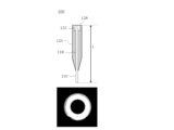
前記照明部は、前記いずれかの流路部材に対し、前記いずれかの内周部の長手方向に沿った光を照射する主照明を有してよい。前記主照明から前記いずれかの内周部に入射した光は、前記いずれかの内周部の先端部から出射することで、前記微細対象物を直上から照明してよい。前記いずれかの照明部は、前記いずれかの流路部材を円周状に囲むリング状の光を照射し、前記微細対象物を斜め方向から照射する副照明を有してよい。
The illumination unit may have a main illumination that irradiates any one of the flow path members with light along the longitudinal direction of any one of the inner peripheries. The light that enters any one of the inner peripheries from the main illumination may be emitted from the tip of any one of the inner peripheries to illuminate the micro-object from directly above. Any one of the illumination units may have a secondary illumination that irradiates a ring-shaped light that circumferentially surrounds any one of the flow path members and illuminates the micro-object from an oblique direction.
前記いずれかの照明部は、光源を有してよい。前記いずれかの照明部は、前記光源の光を、中心光と、前記中心光の周囲を取り囲む周辺光とに分割するフィルタを有してよい。前記いずれかの照明部は、前記フィルタから前記中心光を集光して前記いずれかの内周部に入射させ、前記いずれかの内周部の先端部から光を出射することで前記微細対象物を直上から照明し、前記周辺光を集光して前記微細対象物を斜め方向から照明する集光レンズを有してよい。
Any of the illumination units may have a light source. Any of the illumination units may have a filter that divides light from the light source into central light and peripheral light surrounding the central light. Any of the illumination units may have a condensing lens that condenses the central light from the filter and makes it incident on any of the inner peripheral parts, and emits light from a tip of any of the inner peripheral parts to illuminate the fine object from directly above, and condenses the peripheral light to illuminate the fine object from an oblique direction.
前記いずれかの照明部は、コヒーレント光を照射してよい。前記コヒーレント光は、照明NA(開口数)がほぼゼロの照明光であってよい。前記コヒーレント光は、コヒーレンス関数の幅が波長に比べて十分広くてよい。前記光源は、ハロゲンランプの光、水銀ランプの光、LEDの光またはレーザー光であってよい。
Any of the illumination units may emit coherent light. The coherent light may be illumination light with an illumination NA (numerical aperture) of approximately zero. The coherent light may have a coherence function with a width sufficiently wide compared to the wavelength. The light source may be light from a halogen lamp, light from a mercury lamp, light from an LED, or laser light.
前記いずれかの微細対象物操作装置は、前記微細対象物を載置する載置部をさらに有してよい。前記いずれかの微細対象物操作装置は、前記載置部を基準として前記いずれかの流路部材とは反対側の面に配置される、前記微細対象物を拡大して撮像する撮像部をさらに有してよい。前記撮像部は、前記いずれかの内周部の先端部に近接した前記微細対象物が前記流体によってなされる操作を撮像してよい。前記操作は、前記いずれかの内周部の前記いずれかの先端部に形成されて維持された気泡によって操作されてよい。
Any of the micro-object manipulation devices may further have a placement section on which the micro-object is placed. Any of the micro-object manipulation devices may further have an imaging section that is arranged on the surface opposite any of the flow path members with respect to the placement section and that magnifies and images the micro-object. The imaging section may image the manipulation of the micro-object by the fluid in the vicinity of the tip of any of the inner peripheries. The manipulation may be performed by air bubbles formed and maintained at any of the tip of any of the inner peripheries.
前記いずれかの微細対象物操作装置は、前記いずれかの照明部の照度を調整する照度調整部をさらに有してよい。前記いずれかの撮像部の撮像素子のうち、前記いずれかの流路部材の直下に位置する撮像素子の感度または画像の輝度を、前記いずれかの流路部材の直下の周囲に位置する撮像素子の感度または画像の輝度に基づき調整する調整部をさらに有してよい。前記調整部は、感度調整部、および/または輝度調整部を含んでよい。
Any of the micro-object manipulation devices may further have an illuminance adjustment unit that adjusts the illuminance of any of the illumination units. It may further have an adjustment unit that adjusts the sensitivity or image brightness of an imaging element located directly below any of the flow path members among the imaging elements of any of the imaging units, based on the sensitivity or image brightness of an imaging element located around and directly below any of the flow path members. The adjustment unit may include a sensitivity adjustment unit and/or a brightness adjustment unit.
前記いずれかの微細対象物操作装置は、前記いずれかの撮像部の撮像素子のうち、前記いずれかの流路部材の直下に位置する撮像素子の感度を、前記いずれかの流路部材の直下の周囲に位置する撮像素子の感度に基づき調整(例えば、前記流路部材の直下の周囲に位置する前記撮像素子の前記感度よりも高くまたは低く)する感度調整部をさらに有してよい。
Any of the micro-object manipulation devices may further have a sensitivity adjustment unit that adjusts the sensitivity of an imaging element of any of the imaging units located directly below any of the flow path members based on the sensitivity of an imaging element located in the periphery directly below any of the flow path members (e.g., higher or lower than the sensitivity of the imaging element located in the periphery directly below any of the flow path members).
前記いずれかの微細対象物操作装置は、前記いずれかの撮像部が撮像した画像のうち、前記いずれかの流路部材の直下に位置する画像の輝度を、前記いずれかの流路部材の直下の周囲に位置する画像の輝度に基づき調整(例えば、前記流路部材の直下の周囲に位置する前記画像の前記輝度よりも高くまたは低く)する輝度調整部をさらに有してよい。
Any of the micro-object manipulation devices may further include a brightness adjustment unit that adjusts the brightness of an image captured by any of the imaging units, the image being located directly below any of the flow path members, based on the brightness of an image located in the vicinity directly below any of the flow path members (e.g., higher or lower than the brightness of the image located in the vicinity directly below any of the flow path members).
上記の発明の概要は、本発明の必要な特徴のすべてを列挙したものではない。また、これらの特徴群のサブコンビネーションもまた、発明となりうる。
The above summary of the invention does not list all of the necessary features of the present invention. Also, subcombinations of these features may also constitute inventions.
以下、発明の実施の形態を通じて本発明を説明するが、以下の実施形態は請求の範囲に係る発明を限定するものではない。また、実施形態の中で説明されている特徴の組み合わせのすべてが発明の解決手段に必須であるとは限らない。なお、図面において、同一または類似の部分には同一の参照番号を付して、重複する説明を省く場合がある。
The present invention will be described below through embodiments of the invention, but the following embodiments do not limit the invention according to the claims. Furthermore, not all of the combinations of features described in the embodiments are necessarily essential to the solution of the invention. In the drawings, the same reference numbers are used for the same or similar parts, and duplicate explanations may be omitted.
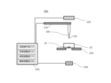
図1は、本実施形態における、微細対象物操作装置200の構成の一例を示す。微細対象物操作装置200は、流路部材100を介して、微細対象物35に操作をすることができる。微細対象物操作装置200は、流路部材100と、支持部210と、照明部220と、載置部230と、撮像部240と、制御部250と、の全部または少なくとも一部を含んでよい。
FIG. 1 shows an example of the configuration of a micro-object manipulation device 200 in this embodiment. The micro-object manipulation device 200 can manipulate a micro-object 35 via a flow path member 100. The micro-object manipulation device 200 may include all or at least a portion of the flow path member 100, a support section 210, an illumination section 220, a mounting section 230, an imaging section 240, and a control section 250.
流路部材100は、流路を備えた部材である。流路部材100は、液体中に存在する微細対象物を操作する。流路部材100は、内周部および外周部を有してよい。詳しくは後述する。
The flow path member 100 is a member equipped with a flow path. The flow path member 100 manipulates microscopic objects present in a liquid. The flow path member 100 may have an inner peripheral portion and an outer peripheral portion. This will be described in more detail later.
支持部210は、流路部材100を支持する。支持部210は、流路部材100の外周部を支持してよい。例えば、支持部210は、流路部材100を支持する。一例として、支持部210は、継手を介して、流路部材100を支持する。
The support part 210 supports the flow path member 100. The support part 210 may support the outer periphery of the flow path member 100. For example, the support part 210 supports the flow path member 100. As one example, the support part 210 supports the flow path member 100 via a joint.
支持部210は、流路部材用アクチュエータ(図示せず)に接続されてよい。例えば、支持部210が流路部材用アクチュエータと接続されることにより、流路部材100は、縦方向、横方向、および上下方向のいずれの方向にも動作できる。流路部材用アクチュエータの動作は、制御部250(例えば、後述する、制御部250の中にある流路操作部255)によって制御されてもよく、観察者の手によって制御されてもよい。
The support section 210 may be connected to an actuator for the flow path member (not shown). For example, by connecting the support section 210 to the actuator for the flow path member, the flow path member 100 can move in any of the vertical, horizontal, and up-down directions. The movement of the actuator for the flow path member may be controlled by the control section 250 (for example, a flow path operation section 255 in the control section 250, which will be described later), or may be controlled by the observer's hand.
支持部210は、光を透過する素材で形成されてよい。支持部210が、光を透過する素材で形成されることにより、照明部220が微細対象物35、および/または流路部材100を照射するときに、支持部210が照明の障害となることを防ぐことができる。例えば、支持部210は、ポリカーボネート樹脂、アクリレート樹脂のような透明なプラスチック、またはガラスであってよいが、これらに限られない。
The support section 210 may be formed of a material that transmits light. By forming the support section 210 from a material that transmits light, it is possible to prevent the support section 210 from obstructing illumination when the illumination section 220 illuminates the micro object 35 and/or the flow path member 100. For example, the support section 210 may be made of a transparent plastic such as polycarbonate resin or acrylate resin, or glass, but is not limited to these.
照明部220は、流路部材100、および/または微細対象物35に光を照射する。照明部220は、支持部210よりも上部に配置されてよい。照明部220は流路部材100を少なくとも部分的に介して微細対象物35に光を照射してよい。例えば、照明部220は、流路部材100の流路を介して、微細対象物35に光を照射する。例えば、照明部220は、リング照明を有する。照明部220は、コヒーレント光を照射してよく、詳細は後述する。
The illumination unit 220 irradiates light onto the flow path member 100 and/or the micro object 35. The illumination unit 220 may be disposed above the support unit 210. The illumination unit 220 may irradiate light onto the micro object 35 at least partially through the flow path member 100. For example, the illumination unit 220 irradiates light onto the micro object 35 via the flow path of the flow path member 100. For example, the illumination unit 220 has a ring illumination. The illumination unit 220 may irradiate coherent light, and details will be described later.
載置部230は、微細対象物35、および/または微細対象物35を収容する容器25を載置する。例えば、載置部230は、縦方向、横方向、および上下方向のいずれの方向にも動作できる。載置部230は、複数の容器、および/またはチューブを搭載してよいが、これらに限られない。載置部230の動作は、載置部230に接続されたコンピュータなどの情報処理装置(例えば、制御部250)によって制御されてもよく、観察者の手によって制御されてもよい。
The mounting unit 230 mounts the micro-object 35 and/or the container 25 that contains the micro-object 35. For example, the mounting unit 230 can move in any of the vertical, horizontal, and up-down directions. The mounting unit 230 may mount multiple containers and/or tubes, but is not limited to this. The operation of the mounting unit 230 may be controlled by an information processing device such as a computer connected to the mounting unit 230 (e.g., the control unit 250), or may be controlled by the observer's hand.
撮像部240は、微細対象物35を撮像し、画像を生成する。例えば、撮像部240は、微細対象物35の透過像を生成し、画像を生成する。一例として、撮像部240は、後述する内周部の先端部に近接した微細対象物35が流体によってなされる操作を撮像する。撮像部240は、透過像を撮像するカメラ(冷却カメラなど)であってよい。
The imaging unit 240 captures an image of the micro-object 35 and generates an image. For example, the imaging unit 240 generates a transmission image of the micro-object 35 and generates an image. As an example, the imaging unit 240 captures an image of an operation performed by a fluid on the micro-object 35 close to the tip of the inner periphery, which will be described later. The imaging unit 240 may be a camera (such as a cooled camera) that captures a transmission image.
撮像部240は、載置部230を基準として流路部材100とは反対側の面に配置されてよい。例えば、撮像部240は、載置部230よりも下部に配置される。撮像部240が、載置部230を基準として流路部材100と反対側の面に配置されることで、流路部材100が微細対象物35を操作する様子を明瞭に撮像できる。撮像部240は、微細対象物35を任意の倍率に拡大して撮像してよい。例えば、撮像部240は、顕微鏡と接続される。一例として、撮像部240は、顕微鏡の光路に配置される対物レンズを用いて、気泡による微細対象物35の操作を拡大して撮像する。接続される顕微鏡としては、倒立型顕微鏡装置や、正立型顕微鏡装置であってよい。
The imaging unit 240 may be disposed on the surface opposite the flow path member 100 with respect to the mounting unit 230. For example, the imaging unit 240 is disposed lower than the mounting unit 230. By disposing the imaging unit 240 on the surface opposite the flow path member 100 with respect to the mounting unit 230, the flow path member 100 can clearly image the manner in which the micro-object 35 is manipulated by the micro-object 35. The imaging unit 240 may image the micro-object 35 by enlarging it to any magnification. For example, the imaging unit 240 is connected to a microscope. As an example, the imaging unit 240 uses an objective lens disposed in the optical path of the microscope to magnify and image the manipulation of the micro-object 35 by the air bubble. The microscope to be connected may be an inverted microscope device or an upright microscope device.
撮像部240は、載置部230を基準として流路部材100と同じ側の面に配置されてもよい。例えば、撮像部240は、流路部材100の真上または真横に配置される。撮像部240が流路部材100の真上または真横に配置されることでも、流路部材100が微細対象物35を操作する様子を明瞭に撮像できる。
The imaging unit 240 may be disposed on the same side as the flow path member 100 with respect to the placement unit 230. For example, the imaging unit 240 is disposed directly above or beside the flow path member 100. By disposing the imaging unit 240 directly above or beside the flow path member 100, it is possible to clearly image the manner in which the flow path member 100 manipulates the micro-object 35.
撮像部240が生成した画像のデータは、撮像部240に接続された情報処理装置(例えば、制御部250)の内部のハードディスク、またはCDなどの情報伝達媒体に格納されてよいし、情報処理装置にさらに接続されたプリンタやディスプレイなどから出力されてもよい。
The image data generated by the imaging unit 240 may be stored on an internal hard disk of an information processing device (e.g., the control unit 250) connected to the imaging unit 240, or on an information transmission medium such as a CD, or may be output from a printer or display further connected to the information processing device.
制御部250は、微細対象物操作装置200の動作の制御全般を行う。例えば、制御部250は、流路部材100の動作、照明部220の照度、載置部230の動作、撮像部240の撮像素子の感度、および撮像部240が撮像した画像の輝度の全部、または少なくとも一部を制御する。制御部250は、支持部210、照明部220、載置部230、および撮像部240の全部または一部と接続されてよい。例えば、制御部250は、情報処理装置(コンピュータ)、および/または、ソフトウェアにより実現されてよい。制御部250は、流路操作部255と、照度調整部260と、感度調整部270と、輝度調整部280と、の全部または少なくとも一部を備えてよい。
The control unit 250 performs overall control of the operation of the micro object manipulation device 200. For example, the control unit 250 controls all or at least a part of the operation of the flow path member 100, the illuminance of the illumination unit 220, the operation of the mounting unit 230, the sensitivity of the image sensor of the imaging unit 240, and the brightness of the image captured by the imaging unit 240. The control unit 250 may be connected to all or a part of the support unit 210, the illumination unit 220, the mounting unit 230, and the imaging unit 240. For example, the control unit 250 may be realized by an information processing device (computer) and/or software. The control unit 250 may include all or at least a part of the flow path manipulation unit 255, the illuminance adjustment unit 260, the sensitivity adjustment unit 270, and the brightness adjustment unit 280.
流路操作部255は、流路部材用アクチュエータの動作を制御して、流路部材100を動作させる。流路操作部255は、制御部250の内部にあってよい。流路操作部255は、自動的に流路部材用アクチュエータの動作を制御してよく、観察者からの入力を受けて動作を制御してもよい。
The flow path operation unit 255 controls the operation of the flow path member actuator to operate the flow path member 100. The flow path operation unit 255 may be located inside the control unit 250. The flow path operation unit 255 may automatically control the operation of the flow path member actuator, or may control the operation by receiving input from an observer.
照度調整部260は、照明部220の照度を調整する。例えば、照度調整部260は、照明部220の照度を、微細対象物35を適切に照明するように調整する。照度調整部260は、制御部250の内部にあってよい。照明部220が複数個の照明および/または領域を含む場合、照度調整部260は、照明および/または領域ごとに照度を調整してよい。照度調整部260は、自動的に照度を調整してもよく、観察者の手によって照度を調整してもよい。
The illuminance adjustment unit 260 adjusts the illuminance of the lighting unit 220. For example, the illuminance adjustment unit 260 adjusts the illuminance of the lighting unit 220 so as to properly illuminate the fine object 35. The illuminance adjustment unit 260 may be located inside the control unit 250. If the lighting unit 220 includes multiple lights and/or regions, the illuminance adjustment unit 260 may adjust the illuminance for each light and/or region. The illuminance adjustment unit 260 may adjust the illuminance automatically, or the illuminance may be adjusted manually by the observer.
感度調整部270は、撮像部240の撮像素子の感度を調整する。例えば、感度調整部270は、撮像素子の受光感度を調整してよく、詳細は後述する。感度調整部270は、制御部250の内部にあってよい。感度調整部270は、自動的に感度を調整してもよく、観察者の手によって感度を調整してもよい。撮像素子は、CMOSイメージセンサー(Complementary Metal Oxide Semiconductor)またはCCDイメージセンサー(Charge Coupled Device)であってよい。
The sensitivity adjustment unit 270 adjusts the sensitivity of the imaging element of the imaging unit 240. For example, the sensitivity adjustment unit 270 may adjust the light receiving sensitivity of the imaging element, as will be described in detail below. The sensitivity adjustment unit 270 may be located inside the control unit 250. The sensitivity adjustment unit 270 may adjust the sensitivity automatically, or the sensitivity may be adjusted manually by the observer. The imaging element may be a CMOS image sensor (Complementary Metal Oxide Semiconductor) or a CCD image sensor (Charge Coupled Device).
輝度調整部280は、撮像部240が撮像した画像の輝度値を調整する。例えば、輝度調整部280は、画像中の特定の領域のみ、輝度を高くするように増幅させてよく、または、輝度を低くするように減衰させてもよい。輝度調整部280は、制御部250の内部にあってよい。輝度調整部280は、自動的に輝度を調整してもよく、観察者の手によって輝度を調整してもよい。輝度調整部280は、輝度に代えて/加えて、明度または光度を調整してもよい。
The brightness adjustment section 280 adjusts the brightness value of the image captured by the imaging section 240. For example, the brightness adjustment section 280 may amplify to increase the brightness only in a specific area in the image, or may attenuate to decrease the brightness. The brightness adjustment section 280 may be inside the control section 250. The brightness adjustment section 280 may adjust the brightness automatically, or the brightness may be adjusted manually by the observer. The brightness adjustment section 280 may adjust the lightness or luminosity instead of/in addition to the brightness.
感度調整部270および輝度調整部280は、あわせて調整部として構成されてもよい。この場合、調整部は、撮像部240の撮像素子のうち、流路部材100の直下に位置する撮像素子の感度および/または画像の輝度を、流路部材100の直下の周囲に位置する撮像素子の感度および/または画像の輝度に基づき調整してよい。
The sensitivity adjustment section 270 and the brightness adjustment section 280 may be configured together as an adjustment section. In this case, the adjustment section may adjust the sensitivity and/or image brightness of the imaging element located directly below the flow path member 100 among the imaging elements of the imaging section 240, based on the sensitivity and/or image brightness of the imaging elements located around and directly below the flow path member 100.
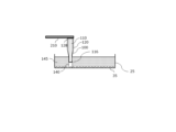
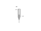
図2は、本実施形態における、流路部材100の一例を示す。流路部材100は、流路内に流体を通過させて、液体中に存在する微細対象物35を操作することができる。流路は、吸引(吸気)または吐出(給気)される流体が通過する。流路は、流路部材100の長手方向を通過するように設けられる。
FIG. 2 shows an example of a flow path member 100 in this embodiment. The flow path member 100 is capable of manipulating a micro object 35 present in a liquid by passing a fluid through the flow path. The flow path is passed by a fluid to be sucked (intake) or discharged (supply). The flow path is provided so as to pass through the longitudinal direction of the flow path member 100.
流体は、気体および/または液体であってよい。気体は空気であってよく、水分を含んでいてもよい。気体は滅菌されていてよい。例えば、流路部材100を通過した気体が液体に排出されることで気泡が形成され、この気泡を用いて液体中に存在する微細対象物35を操作できる。流路は、流体とともに微細対象物35を通過させてよい。
The fluid may be a gas and/or a liquid. The gas may be air and may contain moisture. The gas may be sterile. For example, gas that has passed through the flow path member 100 is discharged into the liquid to form bubbles, which can be used to manipulate micro-objects 35 present in the liquid. The flow path may pass micro-objects 35 along with the fluid.
微細対象物35は、位相物体であってよい。位相物体は、光が入射したとき、その光に位相の変化を与える物体である。位相物体は、透明な物体であってよい。例えば、位相物体は、生物体、液滴構造(ミセル、エマルジョンなど)、または微細な浮遊物(ごみなど)である。生物体は、有機生命体であってよい。例えば、生物体は、細胞である。一例として、細胞は、動物細胞、または植物細胞である。一例として、細胞は、生細胞、または死細胞である。
The microscopic object 35 may be a phase object. A phase object is an object that imparts a phase change to light when the light is incident on the phase object. The phase object may be a transparent object. For example, the phase object is a living organism, a droplet structure (micelle, emulsion, etc.), or a microscopic suspended matter (such as debris). The living organism may be an organic life form. For example, the living organism is a cell. As an example, the cell is an animal cell or a plant cell. As an example, the cell is a living cell or a dead cell.
生物体は、細胞以外の微小な生物体であってもよい。一例として、微小な生物体は、微生物、菌類、藻類、ウイルス類、生体組織、スフェロイドである。微小な生物体は、細胞内のオルガネラを含んでもよい。
The organism may be a microorganism other than a cell. By way of example, the microorganism may be a microorganism, a fungus, an algae, a virus, a living tissue, or a spheroid. The microorganism may include an organelle within a cell.
流路部材100は、内周部110および外周部120を有してよい。
The flow path member 100 may have an inner peripheral portion 110 and an outer peripheral portion 120.
内周部110は、流体の流路となる空洞を有し、流体と接する。流路は、吸気または給気される流体を内部に連通する細長い筒状または円柱形状であってよい。例えば、内周部110は、ストロー形状または毛細管形状である。
The inner periphery 110 has a cavity that serves as a fluid flow path and is in contact with the fluid. The flow path may be an elongated tubular or cylindrical shape that connects the intake or supply fluid to the inside. For example, the inner periphery 110 is straw-shaped or capillary-shaped.
内周部110の長手方向の長さは、1mm以上50mm以下であってよい。内周部110の長手方向の長さは、5mm以上30mm以下であってよい。内周部110の長手方向の長さは、10mm以上20mm以下であってよい。
The longitudinal length of the inner circumferential portion 110 may be 1 mm or more and 50 mm or less. The longitudinal length of the inner circumferential portion 110 may be 5 mm or more and 30 mm or less. The longitudinal length of the inner circumferential portion 110 may be 10 mm or more and 20 mm or less.
流路の内径は、1μm以上10000μm以下であってよい。流路の内径は、10μm以上1000μm以下であってよい。流路の内径は、20μm以上500μm以下であってよい。流路の内径および/または長手方向の長さが上記範囲のときに、流路部材100は、流体を一定量以上保持できるので微細対象物35の操作が容易になる。また、流路部材100が長すぎて、先端部116を意図した位置に導く操作が困難になることもない。
The inner diameter of the flow path may be 1 μm or more and 10,000 μm or less. The inner diameter of the flow path may be 10 μm or more and 1,000 μm or less. The inner diameter of the flow path may be 20 μm or more and 500 μm or less. When the inner diameter and/or longitudinal length of the flow path are within the above ranges, the flow path member 100 can hold more than a certain amount of fluid, making it easy to operate the micro-object 35. In addition, the flow path member 100 is not too long, making it difficult to guide the tip 116 to the intended position.
内周部110は、内側領域112および先端領域114を含んでよい。内側領域112は、外周部120により取り囲まれる領域である。先端領域114は、外周部120により取り囲まれない領域であり、一定の長さを有する。先端領域114は、微細対象物35と近接する先端部116を含む。先端部116は、微細対象物35が浸される液体中に配置されてよい。流路が先端部116に気体を導入することで、先端部116は気泡を形成してよい。先端部116が気泡を形成することにより、微細対象物35を操作する方法の詳細については後述する。ここで、「近接」とは、微細対象物35に物理的影響を及ぼすことが可能な距離を意味してよい。一例として、「近接」とは、微細対象物35と先端部116とが、先端部116に形成される気泡を介して接触可能な距離である。
The inner circumference 110 may include an inner region 112 and a tip region 114. The inner region 112 is a region surrounded by the outer circumference 120. The tip region 114 is a region not surrounded by the outer circumference 120 and has a certain length. The tip region 114 includes a tip portion 116 that is in close proximity to the micro object 35. The tip portion 116 may be disposed in a liquid in which the micro object 35 is immersed. The tip portion 116 may form bubbles by introducing gas into the tip portion 116 through the flow path. The method of manipulating the micro object 35 by the tip portion 116 forming bubbles will be described in detail later. Here, "closeness" may mean a distance at which the micro object 35 can be physically affected. As an example, "closeness" is a distance at which the micro object 35 and the tip portion 116 can come into contact with each other through bubbles formed at the tip portion 116.
先端部116の先端面は、内周部110の長手方向と垂直であってよい。これに代えて、先端面は、当該長手方向との垂直面から傾いた面であってもよい。当該長手方向の垂直面と当該傾いた面とのなす角は、20度以下であってよい。
The tip surface of the tip portion 116 may be perpendicular to the longitudinal direction of the inner circumference portion 110. Alternatively, the tip surface may be a surface that is inclined from a plane perpendicular to the longitudinal direction. The angle between the plane perpendicular to the longitudinal direction and the inclined surface may be 20 degrees or less.
内周部110は、ガラス管であってよい。例えば、ガラス管は、手引き法、ダンナー法、ベロー法などの公知のガラス成形技術により成形される。内周部110は、樹脂管であってもよいが、外周部120よりも強度が高いことが望ましい。
The inner peripheral portion 110 may be a glass tube. For example, the glass tube is formed by a known glass forming technique such as the hand drawing method, the Danner method, or the Bellow method. The inner peripheral portion 110 may be a plastic tube, but it is desirable that the plastic tube has a higher strength than the outer peripheral portion 120.
外周部120は、内周部110の全体または一部を外側から包囲することで、内周部110を保持し、これにより内周部110を保護する。図2において外周部120は斜線ハッチングで示される領域である。外周部120は、先端部116と反対側の端部128において、支持部210に支持される。これにより、流路部材100が支持される。外周部120の長手方向の長さは、2mm以上100mm以下であってよい。外周部120の長手方向の長さは、10mm以上60mm以下であってよい。外周部120の長手方向の長さは、20mm以上40mm以下であってよい。
The outer peripheral portion 120 holds the inner peripheral portion 110 by surrounding all or part of the inner peripheral portion 110 from the outside, thereby protecting the inner peripheral portion 110. In FIG. 2, the outer peripheral portion 120 is the area indicated by diagonal hatching. The outer peripheral portion 120 is supported by the support portion 210 at the end portion 128 opposite the tip portion 116. This supports the flow path member 100. The longitudinal length of the outer peripheral portion 120 may be 2 mm or more and 100 mm or less. The longitudinal length of the outer peripheral portion 120 may be 10 mm or more and 60 mm or less. The longitudinal length of the outer peripheral portion 120 may be 20 mm or more and 40 mm or less.
外周部120の長手方向の長さが上記範囲のときに、外周部120は内周部110を適切に保持および保護できる。外周部120が過度に短い場合、内周部110を保持および保護することが難しい。外周部120が過度に長い場合、先端部116を意図した位置に導く操作が困難になる。
When the longitudinal length of the outer circumferential portion 120 is within the above range, the outer circumferential portion 120 can adequately hold and protect the inner circumferential portion 110. If the outer circumferential portion 120 is too short, it is difficult to hold and protect the inner circumferential portion 110. If the outer circumferential portion 120 is too long, it is difficult to guide the tip portion 116 to the intended position.
外周部120は、内側領域112で、内周部110を取り囲んでよい。例えば、外周部120は、内側領域112の先端領域114側にある包囲部124で内周部110を取り囲む。外周部120は、内側領域112の先端領域114側と反対側では内周部110を取り囲まなくてよい。内周部110は、外周部120から当該反対側に向けて突出する突出部118を有してよい。突出部118は、外周部120および後述する空隙部122によって取り囲まれる内周部110の部分である。
The outer periphery 120 may surround the inner periphery 110 with the inner region 112. For example, the outer periphery 120 surrounds the inner periphery 110 with an enclosing portion 124 on the tip region 114 side of the inner region 112. The outer periphery 120 does not have to surround the inner periphery 110 on the side opposite the tip region 114 side of the inner region 112. The inner periphery 110 may have a protruding portion 118 that protrudes from the outer periphery 120 toward the opposite side. The protruding portion 118 is a portion of the inner periphery 110 that is surrounded by the outer periphery 120 and a void portion 122 described below.
外周部120は、内周部110の一部または全部に接触して、内周部110を取り囲んでよい。例えば、外周部120は、内周部110との接触面以外の面とは接触せずに、内周部110を取り囲む部分を有する。この場合、内周部110と外周部120との間には、空隙となる空隙部122が存在する。この場合、外周部120は、中空部材である。
The outer peripheral portion 120 may be in contact with a part or all of the inner peripheral portion 110 and surround the inner peripheral portion 110. For example, the outer peripheral portion 120 has a portion that surrounds the inner peripheral portion 110 without contacting any surface other than the contact surface with the inner peripheral portion 110. In this case, a void portion 122 that is a gap exists between the inner peripheral portion 110 and the outer peripheral portion 120. In this case, the outer peripheral portion 120 is a hollow member.
外周部120は、内周部110および空隙部122に相当する中心部分が空隙になった円柱または多角柱の形状を有してよい。この場合、外周部120は、円柱の少なくとも一部が円錐または円錐台になっていてよく、多角柱の少なくとも一部が多角錐または多角錐台になっていてもよい。ここで、円錐、円錐台、多角錐および多角錐台の中心軸は内周部110の長手方向の中心軸と一致してよい。
The outer peripheral portion 120 may have the shape of a cylinder or polygonal prism with a gap in the center portion corresponding to the inner peripheral portion 110 and the gap portion 122. In this case, the outer peripheral portion 120 may have at least a part of a cylinder that is a cone or a truncated cone, and at least a part of a polygonal prism that is a polygonal pyramid or a truncated polygonal pyramid. Here, the central axis of the cone, truncated cone, polygonal pyramid, and truncated polygonal pyramid may coincide with the central axis of the inner peripheral portion 110 in the longitudinal direction.
例えば、外周部120は、内側領域112の先端領域114側(例えば、包囲部124の全部または一部)において、先端部116に向かうにつれて、内周部110の長手方向に直交する平面における断面の面積が減少するテーパー形状を有する。外周部120が、内側領域112の先端領域114側でテーパー形状を有することにより、照明部220が微細対象物35を照射するときに、流路部材100の直下(流路部材100の長手方向の鉛直下方)の周囲にある微細対象物35を明るく照明できる。詳細は後述する。
For example, the outer circumferential portion 120 has a tapered shape on the tip region 114 side of the inner region 112 (e.g., all or part of the surrounding portion 124) in which the cross-sectional area in a plane perpendicular to the longitudinal direction of the inner circumferential portion 110 decreases toward the tip portion 116. By having the outer circumferential portion 120 have a tapered shape on the tip region 114 side of the inner region 112, when the illumination unit 220 illuminates the micro-object 35, the micro-object 35 located around and directly below the flow path member 100 (vertically below the flow path member 100 in the longitudinal direction) can be brightly illuminated. Details will be described later.
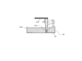
図2では、外周部120の先端部116と反対側の端面(図2の上側の端面)は、内周部110の当該反対側の端面(図2の上側の端面)と一致しているが(図2の端部128)、外周部120の端面と内周部110の端面との位置はこれに限られない。例えば、内周部110の上側の端面は、外周部120の上側の端面よりも下側に位置してもよい。この場合、外周部120は、空隙部122に流体を保持できる容器の形態となる。ここで、流体および/または微細対象物35を回収後に、流路部材100の先端領域114を折る、または切断して、必要に応じて封止することにより、外周部120を、微細対象物35や液体を収納する容器としてそのまま用いてよい。
2, the end face of the outer peripheral portion 120 opposite the tip portion 116 (the upper end face in FIG. 2) coincides with the opposite end face of the inner peripheral portion 110 (the upper end face in FIG. 2) (end 128 in FIG. 2), but the positions of the end faces of the outer peripheral portion 120 and the inner peripheral portion 110 are not limited to this. For example, the upper end face of the inner peripheral portion 110 may be located lower than the upper end face of the outer peripheral portion 120. In this case, the outer peripheral portion 120 is in the form of a container that can hold a fluid in the void portion 122. Here, after the fluid and/or the fine object 35 is collected, the tip region 114 of the flow path member 100 is folded or cut and sealed as necessary, so that the outer peripheral portion 120 can be used as it is as a container for storing the fine object 35 or liquid.
外周部120は、内周部110よりも、成形が容易な材料で形成されてよい。外周部120は、ガラスよりも成形が容易な樹脂を材料として用いてよい。外周部120の成形は、インサート成形、または射出成形である。インサート成形の場合、まず内周部110(例えば、ガラス管)を金型の中にセットする。次に、外周部120を形成する材料を金型に充填する。
The outer peripheral portion 120 may be formed from a material that is easier to mold than the inner peripheral portion 110. The outer peripheral portion 120 may be formed from a resin that is easier to mold than glass. The outer peripheral portion 120 is formed by insert molding or injection molding. In the case of insert molding, the inner peripheral portion 110 (e.g., a glass tube) is first set in a mold. Next, the material that will form the outer peripheral portion 120 is filled into the mold.
外周部120を成形した後に、内周部110を外周部120の先端に貫通させることにより、流路部材100を製造してもよい。この場合、内周部110と外周部120とを別々に用意した後で流路部材100を製造できるため、観察者が所望する部材の流路部材100を製造できる。
After molding the outer peripheral portion 120, the flow path member 100 may be manufactured by penetrating the inner peripheral portion 110 to the tip of the outer peripheral portion 120. In this case, the flow path member 100 can be manufactured after the inner peripheral portion 110 and the outer peripheral portion 120 are prepared separately, so that the flow path member 100 of the component desired by the observer can be manufactured.
外周部120を形成する材料は、内周部110を形成する材料よりも、溶融化する温度が低くてよい。例えば、外周部120を形成する材料は、内周部110を形成する材料よりも、融点が低い。このことにより、外周部120を形成する材料は、内周部110を形成する材料よりも低い温度で溶融でき、任意の形状への成形が容易になる。
The material forming the outer circumferential portion 120 may have a lower melting temperature than the material forming the inner circumferential portion 110. For example, the material forming the outer circumferential portion 120 has a lower melting point than the material forming the inner circumferential portion 110. This allows the material forming the outer circumferential portion 120 to melt at a lower temperature than the material forming the inner circumferential portion 110, making it easier to mold into any shape.
例えば、外周部120を形成する材料は、内周部110を形成する材料よりも、ガラス転移点が低い。このことにより、外周部120を形成する材料は、内周部110を形成する材料よりも低い温度で柔らかくなるため、任意の形状への成形が容易になる。ガラス転移点の測定は、示差走査熱量計を用いて行ってよいが、これに限らない。
For example, the material forming the outer circumferential portion 120 has a lower glass transition point than the material forming the inner circumferential portion 110. As a result, the material forming the outer circumferential portion 120 becomes soft at a lower temperature than the material forming the inner circumferential portion 110, making it easier to mold into any shape. Measurement of the glass transition point may be performed using a differential scanning calorimeter, but is not limited to this.
外周部120を形成する材料は、内周部110を形成する材料よりも、変形しやすくてよい。例えば、外周部120を形成する材料は、内周部110を形成する材料よりも、室温(例えば、約20℃、約25℃、または約30℃など)におけるヤング率が低い。ヤング率は、ひずみと応力との関係を示す値であり、その値が小さいほど、変形しやすい材料であることを示す。このことにより、外周部120を形成する材料は、内周部110を形成する材料よりも変形がしやすく、任意の形状への成形が容易になる。ヤング率の測定は、ASTM D638の規格にしたがって行ってよいが、これに限らない。
The material forming the outer circumferential portion 120 may be more easily deformed than the material forming the inner circumferential portion 110. For example, the material forming the outer circumferential portion 120 has a lower Young's modulus at room temperature (e.g., about 20°C, about 25°C, or about 30°C, etc.) than the material forming the inner circumferential portion 110. Young's modulus is a value that indicates the relationship between strain and stress, and the smaller the value, the easier the material is to deform. This makes the material forming the outer circumferential portion 120 more easily deformable than the material forming the inner circumferential portion 110, making it easier to mold into any shape. The measurement of Young's modulus may be performed according to the ASTM D638 standard, but is not limited to this.
内周部110を形成する材料は、外周部120を形成する材料よりも、波長400nm、450nm、500nm、550nm、600nm、650nmまたは700nmにおける光透過率の値が大きくてよい。内周部110を形成する材料は、外周部120を形成する材料よりも、波長400nmから700nmの可視光領域のすべての波長における光透過率の値が大きくてよい。内周部110を形成する材料は、外周部120を形成する材料よりも、波長400nm、450nm、500nm、550nm、600nm、650nmまたは700nmにおける光の散乱性が小さくてよい。光透過率および/または散乱性の測定は、分光光度計を用いて行ってよいが、これに限らない。
The material forming the inner peripheral portion 110 may have a higher light transmittance value at wavelengths of 400 nm, 450 nm, 500 nm, 550 nm, 600 nm, 650 nm, or 700 nm than the material forming the outer peripheral portion 120. The material forming the inner peripheral portion 110 may have a higher light transmittance value at all wavelengths in the visible light range from 400 nm to 700 nm than the material forming the outer peripheral portion 120. The material forming the inner peripheral portion 110 may have a lower light scattering property at wavelengths of 400 nm, 450 nm, 500 nm, 550 nm, 600 nm, 650 nm, or 700 nm than the material forming the outer peripheral portion 120. The light transmittance and/or scattering property may be measured using a spectrophotometer, but is not limited to this.
内周部110を形成する材料が、外周部120を形成する材料よりも、光透過率の値が大きいことで、内周部110を形成する材料は光を透過しやすく、照明部220が流路部材100に光を照射して、光が内周部110を介して微細対象物35を照明するのに有利である。
The material forming the inner circumference 110 has a higher light transmittance value than the material forming the outer circumference 120, so the material forming the inner circumference 110 transmits light more easily, which is advantageous for the illumination unit 220 to irradiate the flow path member 100 with light, and for the light to illuminate the micro-object 35 through the inner circumference 110.
内周部110を形成する材料は、外周部120を形成する材料よりも、室温における屈折率の値が小さくてよい。内周部110を形成する材料と、外周部120を形成する材料との屈折率の差が0.2以上あるとよい。この屈折率の差が0.3以上であってよい。この屈折率の差が0.5以上であってよい。光の屈折率の測定は、臨界角法を用いて行ってよいが、これに限らない。
The material forming the inner peripheral portion 110 may have a smaller refractive index at room temperature than the material forming the outer peripheral portion 120. The difference in refractive index between the material forming the inner peripheral portion 110 and the material forming the outer peripheral portion 120 may be 0.2 or more. This difference in refractive index may be 0.3 or more. This difference in refractive index may be 0.5 or more. The refractive index of light may be measured using the critical angle method, but is not limited to this.
外周部120を形成する材料の屈折率が、内周部110を形成する材料の屈折率よりも0.2以上大きいことで、外周部120から内周部110へ光が入射しようとしても、外周部120と内周部110との境界で光が全反射を起こすことが可能になる。そのため、外周部120から内周部110へ光が入り込むことを抑えることができる。
The refractive index of the material forming the outer circumferential portion 120 is at least 0.2 greater than the refractive index of the material forming the inner circumferential portion 110, so that even if light attempts to enter the inner circumferential portion 110 from the outer circumferential portion 120, the light can be totally reflected at the boundary between the outer circumferential portion 120 and the inner circumferential portion 110. This makes it possible to prevent light from entering the inner circumferential portion 110 from the outer circumferential portion 120.
内周部110を形成する材料は、精密加工が可能で強度の高い材料であれば制限なく用いることができる。例えば、内周部110を形成する材料は、ガラスまたは金属である。一例として、ガラスは、ホウケイ酸ガラス、ソーダ石灰ガラスなどである。一例として、金属は、ステンレス鋼、チタン合金、アルミニウム合金などである。ホウケイ酸ガラスの融点は約820℃、アルミニウムの融点は約660℃である。
The material forming the inner circumference 110 can be any material that can be precisely machined and has high strength, without any restrictions. For example, the material forming the inner circumference 110 is glass or metal. Examples of glass include borosilicate glass and soda-lime glass. Examples of metals include stainless steel, titanium alloys, and aluminum alloys. The melting point of borosilicate glass is approximately 820°C, and the melting point of aluminum is approximately 660°C.
外周部120を形成する材料は、成形が可能な材料であれば制限なく用いることができる。例えば、外周部120を形成する材料は、樹脂である。一例として、樹脂は、ポリプロピレン樹脂、ポリエチレン樹脂、ポリスチレン樹脂、PET樹脂、ポリ塩化ビニル樹脂、ポリカーボネート樹脂などであってよいが、これらに限られない。ポリカーボネート樹脂の融点は約150℃である。
The material forming the outer periphery 120 can be any material that can be molded without any restrictions. For example, the material forming the outer periphery 120 is a resin. As an example, the resin may be polypropylene resin, polyethylene resin, polystyrene resin, PET resin, polyvinyl chloride resin, polycarbonate resin, etc., but is not limited to these. The melting point of polycarbonate resin is approximately 150°C.
例えば、ガラスのみで流路部材100の外形の形状を再現する場合、同じ形状を量産することは困難であり、長手方向の長さを短くすることも困難である。さらに、樹脂により再現可能な任意の形状をガラスで再現することが困難である。また、例えば、樹脂のみで流路部材100の外形の形状を再現する場合、光学特性や微細形状における強度がガラスに比べると不十分である。
For example, when reproducing the external shape of the flow path member 100 using only glass, it is difficult to mass-produce the same shape, and it is also difficult to shorten the longitudinal length. Furthermore, it is difficult to reproduce any shape that can be reproduced using resin using glass. Also, for example, when reproducing the external shape of the flow path member 100 using only resin, the optical properties and strength of the fine shape are insufficient compared to glass.
そこで、流路部材100は、強度は弱いものの成形が容易な外周部120と、成形は難しいものの強度の高い内周部110とを備えることで、内周部110および外周部120の両方の長所を生かすことができる。このようにして得られる流路部材100は、微細対象物35を容易に操作することができ、また、廉価で大量に製造できる。
Then, the flow path member 100 has an outer periphery 120 which is weak but easy to mold, and an inner periphery 110 which is difficult to mold but strong, making it possible to utilize the advantages of both the inner periphery 110 and the outer periphery 120. The flow path member 100 obtained in this way allows the micro-object 35 to be easily manipulated, and can be mass-produced at low cost.
図3A、図3B、および図3Cは、本実施形態における、微細対象物35を回収する方法の一例を示す。図3A、図3B、および図3Cでは、微細対象物35の例として、接着細胞の場合を示す。図3Aにおいて、透明な容器25の内底面にある固相で、接着細胞が培養されている。接着細胞は、容器25の中にある液体145に浸されてよい。液体145は、完全培地であっても、基本培地であっても、緩衝液であってもよい。微細対象物35が生物体でない場合や死細胞の場合は、これらに限らず、水や有機溶媒などであってもよい。
Figures 3A, 3B, and 3C show an example of a method for recovering a micro-object 35 in this embodiment. Figures 3A, 3B, and 3C show adherent cells as an example of the micro-object 35. In Figure 3A, the adherent cells are cultured on a solid phase on the inner bottom surface of a transparent container 25. The adherent cells may be immersed in a liquid 145 in the container 25. The liquid 145 may be a complete medium, a basal medium, or a buffer solution. If the micro-object 35 is not a living organism or is a dead cell, the liquid is not limited to these, and may be water, an organic solvent, or the like.
図3Aにおいて、内周部110の、先端部116と反対側の端部128に接続されたポンプ(図示せず)が、内周部110の流路に気体を給気する。これにより、先端部116に気泡140を形成する。形成された気泡140は接着細胞に接触する。ポンプは、気体の給気および吸気を調節して、先端部116に形成された気泡140を維持する。先端部116に形成され、維持された気泡140により、接着細胞の操作が行われてよい。気泡140が維持されることで、接着細胞の操作が容易に行われる。
In FIG. 3A, a pump (not shown) connected to the end 128 of the inner periphery 110 opposite the tip 116 supplies gas to the flow path of the inner periphery 110. This forms a gas bubble 140 at the tip 116. The formed gas bubble 140 comes into contact with the adherent cells. The pump adjusts the supply and intake of gas to maintain the gas bubble 140 formed at the tip 116. The adherent cells may be manipulated using the gas bubble 140 formed and maintained at the tip 116. By maintaining the gas bubble 140, the adherent cells can be easily manipulated.
次に、図3Bにおいて、内周部110の、先端部116と反対側の端部128に接続された支持部210が、接着細胞に気泡140を接触させたまま、流路部材100を固相の表面に沿って移動させる。図2では、支持部210が、左から右方向に流路部材100を移動させた場合を記載しているが、固相の表面に平行な方向であれば、支持部210が流路部材100を移動させる方向は限定されない。
Next, in FIG. 3B, the support part 210 connected to the end part 128 of the inner circumference part 110 opposite the tip part 116 moves the flow path member 100 along the surface of the solid phase while keeping the air bubbles 140 in contact with the adherent cells. In FIG. 2, the support part 210 moves the flow path member 100 from left to right, but the direction in which the support part 210 moves the flow path member 100 is not limited as long as it is a direction parallel to the surface of the solid phase.
支持部210が流路部材100を移動させることで、気泡140が移動し、接着細胞が気泡140に付着、および/または外力を加えられて、接着細胞を固相から剥離できる。このとき、剥離された接着細胞は、気泡140の気液界面に付着する。ポンプを制御することで、給気または吸気する気体の圧力および/または体積を制御できる。これにより、気泡140の大きさを変化できるので、所望の範囲内にある接着細胞を剥離できる。なお、支持部210が流路部材100を固相の表面に沿って移動させる代わりに、載置部230を移動させて、接着細胞を固相から剥離してもよい。
When the support section 210 moves the flow path member 100, the air bubbles 140 move and the adherent cells adhere to the air bubbles 140 and/or an external force is applied, so that the adherent cells can be detached from the solid phase. At this time, the detached adherent cells adhere to the air-liquid interface of the air bubbles 140. By controlling the pump, the pressure and/or volume of the gas being supplied or sucked in can be controlled. This allows the size of the air bubbles 140 to be changed, so that adherent cells within a desired range can be detached. Note that instead of the support section 210 moving the flow path member 100 along the surface of the solid phase, the placement section 230 may be moved to detach the adherent cells from the solid phase.
次に、図3Cにおいて、ポンプが内周部110の流路にある気体を吸気することにより、気泡140に付着している接着細胞を内周部110の内部に回収する。このように、先端部116に形成する気泡140を用いて、接着細胞を固相から選択的に剥離し、回収できる。さらに、回収した細胞を他の容器やスライドガラスに放出して接着細胞を移動させてもよい。これにより、接着細胞を継代培養したり、観察したり、染色したりできる。
Next, in FIG. 3C, the pump sucks in the gas in the flow path of the inner periphery 110, thereby recovering the adherent cells attached to the gas bubbles 140 inside the inner periphery 110. In this way, the gas bubbles 140 formed at the tip 116 can be used to selectively detach and recover the adherent cells from the solid phase. Furthermore, the recovered cells may be released into another container or a slide glass to move the adherent cells. This allows the adherent cells to be subcultured, observed, or stained.
内周部110の流路に気体を給気および吸気することで、流路部材100は、液体中にある微細対象物35を容易に操作できる。
By supplying and suctioning gas into the flow path of the inner circumference 110, the flow path member 100 can easily manipulate the micro-object 35 in the liquid.
微細対象物35として、接着細胞を例示したが、浮遊細胞であってもよい。微細対象物35が浮遊細胞の場合、先端部116に気泡140を形成せず、内周部110の流路に含まれる流体(気体または液体)を吸引して、先端部116と浮遊細胞とを近接させてよく、内周部110の流路内に微細対象物35を取り込んでよい。この操作により、浮遊細胞の観察および/または回収を容易に行うことができる。
Although adherent cells have been exemplified as the micro-object 35, suspended cells may also be used. When the micro-object 35 is a suspended cell, the tip 116 may be brought close to the suspended cell by aspirating the fluid (gas or liquid) contained in the flow path of the inner circumference 110 without forming an air bubble 140 at the tip 116, and the micro-object 35 may be taken into the flow path of the inner circumference 110. This operation makes it easy to observe and/or recover the suspended cell.
接着細胞の操作として、支持部210が、接着細胞に気泡140を接触させたまま、流路部材100を固相の表面に沿って移動させることを例示したが、接着細胞の操作はこれに限られない。例えば、支持部210を固定したまま、気泡140の体積を増加させることで気泡140の気液界面を移動させて、接着細胞を気泡140に付着および/または固相から剥離させても良い。さらに、接着細胞が含まれる培地の成分を変更する、または気泡を形成する時間を調整することで、接着細胞が気泡140に付着および/または固相から剥離したり、気泡140で接着細胞を押圧したりする操作も容易に行うことができる。
As an example of the manipulation of adherent cells, the support section 210 has been shown to move the flow path member 100 along the surface of the solid phase while keeping the air bubbles 140 in contact with the adherent cells, but the manipulation of adherent cells is not limited to this. For example, the volume of the air bubbles 140 may be increased while keeping the support section 210 fixed, thereby moving the air-liquid interface of the air bubbles 140, causing the adherent cells to adhere to the air bubbles 140 and/or detach from the solid phase. Furthermore, by changing the components of the medium containing the adherent cells or adjusting the time for forming the air bubbles, it is also possible to easily perform manipulations such as causing the adherent cells to adhere to the air bubbles 140 and/or detach from the solid phase, or pressing the adherent cells with the air bubbles 140.
図4A、図4Bおよび図4Cは、本実施形態における、流路部材100の一例を示す。図4A、図4Bおよび図4Cの流路部材100は、内周部110を形成する材料としてホウケイ酸ガラスを用い、外周部120を形成する材料として、ポリカーボネート樹脂を用いている。流路部材100は、内周部110と外周部120との間に空隙部122を有する。
FIGS. 4A, 4B, and 4C show an example of a flow path member 100 in this embodiment. The flow path member 100 in FIG. 4A, 4B, and 4C uses borosilicate glass as the material for forming the inner periphery 110, and uses polycarbonate resin as the material for forming the outer periphery 120. The flow path member 100 has a gap 122 between the inner periphery 110 and the outer periphery 120.
図4Aおよび図4Bにそれぞれ示す2つの流路部材100の直上(流路部材100の長手方向の鉛直上方)に照明部220を位置させ、流路部材100を通して先端部116の直下に位置する微細対象物35を照明して撮像した明視野画像を図4Aおよび図4Bにそれぞれ示す。図4Aに示す流路部材100の直下に位置する微細対象物35を撮像したものよりも、図4Bの流路部材100の直下に位置する微細対象物35を撮像したもののほうが、微細対象物35がより明瞭に観察される。なお、撮像にあたり予め流路を液体(例えば、緩衝液、培地など)で充填して撮像してもよい。
FIGS. 4A and 4B show bright field images taken by positioning the illumination unit 220 directly above the two flow path members 100 shown in FIG. 4A and FIG. 4B (vertically above the flow path members 100 in the longitudinal direction) and illuminating the micro object 35 located directly below the tip 116 through the flow path members 100. The micro object 35 can be observed more clearly in an image of the micro object 35 located directly below the flow path member 100 in FIG. 4B than in an image of the micro object 35 located directly below the flow path member 100 shown in FIG. 4A. Note that the flow paths may be filled with liquid (e.g., buffer solution, culture medium, etc.) beforehand before imaging.
照明部220から位相の揃ったコヒーレント光(ここで、コヒーレント光は、照明NAがほぼゼロの照明光であり、コヒーレンス関数の幅が波長に比べて十分広い光であってよい)を微細対象物35に照射することで明瞭な明視野観察像が得られる。照明部220から流路部材100に光を照射すると、ガラスである内周部110を通過した光は位相が乱れず、コヒーレント光が内周部110直下の微細対象物35に照射され、高いコントラストの観察像が得られる。一方、樹脂である外周部120を通過した光は散乱され、位相が乱れたインコヒーレント光となる。外周部120の内部を通過した光が内周部110へ入り込むことにより、微細対象物35を照明する光の位相が乱れ、実効的照明NAが大きくなり(コヒーレンス関数の幅が小さくなる)、明視野観察の際にコントラストが低下し、微細対象物35の画像が不明瞭になる原因となる。
A clear bright-field observation image can be obtained by irradiating the micro-object 35 with coherent light (here, the coherent light is an illumination light with an illumination NA of almost zero and a width of the coherence function sufficiently wide compared to the wavelength) from the illumination unit 220. When the illumination unit 220 irradiates the flow path member 100, the light that passes through the inner circumference 110, which is glass, does not have a phase disturbance, and the coherent light is irradiated to the micro-object 35 directly below the inner circumference 110, and an observation image with high contrast is obtained. On the other hand, the light that passes through the outer circumference 120, which is resin, is scattered and becomes incoherent light with a disturbed phase. When the light that passes through the inside of the outer circumference 120 enters the inner circumference 110, the phase of the light illuminating the micro-object 35 is disturbed, the effective illumination NA becomes large (the width of the coherence function becomes small), and the contrast decreases during bright-field observation, causing the image of the micro-object 35 to become unclear.
そこで、ガラスである内周部110と樹脂である外周部120との接触する部分の面積(接触面積ということがある)を小さくすることで、外周部120の内部を通過した光が内周部110へ入り込むことが抑えられ、微細対象物35が明瞭に観察される。
Therefore, by reducing the area of contact between the inner circumference 110, which is made of glass, and the outer circumference 120, which is made of resin (sometimes called the contact area), light that has passed through the inside of the outer circumference 120 is prevented from entering the inner circumference 110, and the micro-object 35 can be clearly observed.
接触面積は、0.5mm2以上4mm2以下であってよい。接触面積は、0.8mm2以上3mm2以下であってよい。接触面積は、1mm2以上2mm2以下であってよい。
The contact area may be 0.5 mm2 to 4 mm2 inclusive. The contact area may be 0.8 mm2 to 3 mm2 inclusive. The contact area may be 1 mm2 to 2 mm2 inclusive.
接触面積が上記の範囲内にあるときに、微細対象物35が明瞭に観察できる。内周部110と外周部120との接触面積が4mm2超過の場合、外周部120の内部を通過した光が、内周部110へ入り込む量が多くなり、微細対象物35を明瞭に観察することが難しい。内周部110と外周部120との接触面積が0.5mm2未満の場合、流路部材100を製造するための外周部120のインサート成形が困難になる。
When the contact area is within the above range, the micro object 35 can be clearly observed. When the contact area between the inner peripheral portion 110 and the outer peripheral portion 120 exceeds 4 mm2, the amount of light that passes through the inside of the outer peripheral portion 120 entering the inner peripheral portion 110 increases, making it difficult to clearly observe the micro object 35. When the contact area between the inner peripheral portion 110 and the outer peripheral portion 120 is less than 0.5 mm2 , it becomes difficult to insert mold the outer peripheral portion 120 to manufacture the flow path member 100.
図5A、図5B、図5Cおよび図5Dは、本実施形態における、外周部120の空隙率および充填率について説明する図である。外周部120の充填率は、30%以上80%以下であってよい。充填率は、40%以上70%以下であってよい。充填率は、50%以上60%以下であってよい。
FIGS. 5A, 5B, 5C, and 5D are diagrams illustrating the porosity and filling rate of the outer peripheral portion 120 in this embodiment. The filling rate of the outer peripheral portion 120 may be 30% or more and 80% or less. The filling rate may be 40% or more and 70% or less. The filling rate may be 50% or more and 60% or less.
空隙部122の体積を示す指標として、空隙率を定義する。空隙率は、空隙部122を含む外周部120の見かけ上の体積V1に対する、空隙部122の体積V2の割合である。
The porosity is defined as an index showing the volume of the void portion 122. The porosity is the ratio of the volume V2 of the void portion 122 to the apparent volume V1 of the outer peripheral portion 120 including the void portion 122.
図5Aに示す流路部材100について、空隙部122を含む外周部120の見かけ上の体積V1は、外周部120を形成する材料で囲まれた空間領域の体積を意味する(図5Bに示す閉空間の体積)。V1には、空隙部122の体積も含まれる。空隙部の体積V2は、外周部120を形成する材料で囲まれた領域の体積から、外周部120を形成する材料が占める空間領域の体積(つまり、外周部120の実体上の体積)を減じたものを意味する(図5Cに示す白色部の体積)。
For the flow path member 100 shown in FIG. 5A, the apparent volume V1 of the outer peripheral portion 120 including the void portion 122 means the volume of the spatial region surrounded by the material forming the outer peripheral portion 120 (the volume of the closed space shown in FIG. 5B). V1 also includes the volume of the void portion 122. The volume V2 of the void portion means the volume of the region surrounded by the material forming the outer peripheral portion 120 minus the volume of the spatial region occupied by the material forming the outer peripheral portion 120 (i.e., the actual volume of the outer peripheral portion 120) (the volume of the white portion shown in FIG. 5C).
空隙率は、以下の式1により算出されてよい。
[式1]
空隙率(%)=100×(V2/V1)。 The porosity may be calculated by the followingEquation 1.
[Formula 1]
Porosity (%) = 100 x (V2/V1).
[式1]
空隙率(%)=100×(V2/V1)。 The porosity may be calculated by the following
[Formula 1]
Porosity (%) = 100 x (V2/V1).
空隙率の代わりに、充填率を定義してよい。充填率は、空隙部122を含む外周部120の見かけ上の体積V1に対する、空隙部122を含まない外周部120の実体上の体積V3の割合である(図5Dに示す斜線部の体積)。
Instead of the void ratio, a filling ratio may be defined. The filling ratio is the ratio of the actual volume V3 of the outer peripheral portion 120 that does not include the void portion 122 to the apparent volume V1 of the outer peripheral portion 120 that includes the void portion 122 (the volume of the shaded portion shown in FIG. 5D).
充填率は、以下の式2により算出されてよい。
[式2]
充填率(%)=100×(V3/V1)。 The filling rate may be calculated by the followingEquation 2.
[Formula 2]
Filling rate (%) = 100 x (V3/V1).
[式2]
充填率(%)=100×(V3/V1)。 The filling rate may be calculated by the following
[Formula 2]
Filling rate (%) = 100 x (V3/V1).
V2とV3との和がV1であるため、充填率は、以下の式3により算出されてもよい。
[式3]
充填率(%)=100-空隙率。 Since the sum of V2 and V3 is V1, the filling rate may be calculated by the followingEquation 3.
[Formula 3]
Filling rate (%) = 100 - void ratio.
[式3]
充填率(%)=100-空隙率。 Since the sum of V2 and V3 is V1, the filling rate may be calculated by the following
[Formula 3]
Filling rate (%) = 100 - void ratio.
充填率が30%以上80%以下の範囲内にあるときに、微細対象物35が明瞭に観察できる。充填率が80%超過の場合、外周部120の内部を通過した光の、内周部110へ入り込む量が多くなり、微細対象物35を明瞭に観察することが難しい。充填率が30%未満の場合、外周部120の強度が維持できなくなり、内周部110を保持することや、支持部210が外周部120を支持することが難しい。
When the filling rate is within the range of 30% to 80%, the micro-object 35 can be clearly observed. If the filling rate exceeds 80%, a large amount of light that passes through the inside of the outer peripheral portion 120 enters the inner peripheral portion 110, making it difficult to clearly observe the micro-object 35. If the filling rate is less than 30%, the strength of the outer peripheral portion 120 cannot be maintained, making it difficult to hold the inner peripheral portion 110 and for the support portion 210 to support the outer peripheral portion 120.
ここで、図4Aおよび図4Cに示す流路部材100の内周部110の長手方向の長さLは2.0cmであり、内周部110が外周部120の先端部116と反対側の端部128に達している。図4Bに示す流路部材100の内周部110の長手方向の長さLは1.4cmであり、図4Aおよび図4Cに示す流路部材100の内周部110の長手方向の長さに比べて短く、端部128に到達していない。
Here, the longitudinal length L of the inner periphery 110 of the flow path member 100 shown in Figures 4A and 4C is 2.0 cm, and the inner periphery 110 reaches the end 128 opposite the tip 116 of the outer periphery 120. The longitudinal length L of the inner periphery 110 of the flow path member 100 shown in Figure 4B is 1.4 cm, which is shorter than the longitudinal length of the inner periphery 110 of the flow path member 100 shown in Figures 4A and 4C and does not reach the end 128.
図4A、図4B、および図4Cの流路部材100は、空隙部122を含む外周部120の見かけ上の体積V1が等しいが、それぞれ空隙部122の体積V2が異なっている。
The flow path members 100 in Figures 4A, 4B, and 4C have the same apparent volume V1 of the outer periphery 120 including the void portion 122, but the volume V2 of the void portion 122 is different.
ここで、接触面積に関する指標として、接触面積率を以下の式4により定義する。
[式4]
接触面積率(%)=100×{(内周部110と外周部120との接触面積/内周部110の長手方向に直交する平面における断面積)。 Here, as an index relating to the contact area, the contact area ratio is defined by the following formula 4.
[Formula 4]
Contact area ratio (%)=100×{(contact area between innercircumferential portion 110 and outer circumferential portion 120/cross-sectional area in a plane perpendicular to the longitudinal direction of inner circumferential portion 110).
[式4]
接触面積率(%)=100×{(内周部110と外周部120との接触面積/内周部110の長手方向に直交する平面における断面積)。 Here, as an index relating to the contact area, the contact area ratio is defined by the following formula 4.
[Formula 4]
Contact area ratio (%)=100×{(contact area between inner
つまり、接触面積率とは、ガラス管である内周部110の断面積に対する、ガラス管である内周部110と樹脂である外周部120との接触する部分の面積(接触面積)の比率である。図4A、図4Bおよび図4Cで用いた流路部材100の接触面積、充填率、接触面積率を、表1に示す。

In other words, the contact area ratio is the ratio of the area (contact area) of the contact portion between the inner peripheral portion 110 which is a glass tube and the outer peripheral portion 120 which is a resin to the cross-sectional area of the inner peripheral portion 110 which is a glass tube. The contact area, filling rate, and contact area ratio of the flow path member 100 used in Figures 4A, 4B, and 4C are shown in Table 1.
3つの流路部材100の直上にそれぞれ照明部220を位置させ、流路部材100を通して先端部116の直下に位置する微細対象物35を撮像した明視野画像をそれぞれ図4A、図4B、および図4Cに示す。
The illumination units 220 are positioned directly above each of the three flow path members 100, and bright field images of the micro object 35 located directly below the tip 116 through the flow path members 100 are shown in Figures 4A, 4B, and 4C, respectively.
図4Aの流路部材100の直下に位置する微細対象物35を撮像したものでは、微細対象物35の輪郭が認められない。しかし、図4Bの流路部材100の直下に位置する微細対象物35を撮像したものでは、輪郭が認められる。さらに、図4Cの流路部材100の直下に位置する微細対象物35を撮像したものは、より微細対象物35が明瞭に観察されている。この理由として、図4Bおよび図4Cの流路部材100では、図4Aの流路部材100に比べて、空隙部122の体積が大きい(つまり、充填率の値が小さい)ため、外周部120から直接内周部110に入り込む光の量が抑えられる。これにより、照明部220が微細対象物35を照明する光の位相の乱れが抑えられたことによるものと考えられる。
In the image of the micro object 35 located directly below the flow path member 100 in FIG. 4A, the outline of the micro object 35 is not visible. However, in the image of the micro object 35 located directly below the flow path member 100 in FIG. 4B, the outline is visible. Furthermore, in the image of the micro object 35 located directly below the flow path member 100 in FIG. 4C, the micro object 35 is observed more clearly. The reason for this is that in the flow path member 100 in FIG. 4B and FIG. 4C, the volume of the void portion 122 is larger (i.e., the value of the filling rate is smaller) than in the flow path member 100 in FIG. 4A, so the amount of light that directly enters the inner peripheral portion 110 from the outer peripheral portion 120 is reduced. This is thought to be due to the reduction in the phase disturbance of the light with which the illumination unit 220 illuminates the micro object 35.
流路部材100の接触面積率は、50000%(500倍)以下、または30000%(300倍)以下であってよい。接触面積率が50000%(500倍)以下、または30000%(300倍)以下の範囲内にあると、微細対象物35が明瞭に観察できる。
The contact area ratio of the flow path member 100 may be 50,000% (500x) or less, or 30,000% (300x) or less. When the contact area ratio is within the range of 50,000% (500x) or less, or 30,000% (300x) or less, the micro-object 35 can be clearly observed.
内周部110と外周部120とが接触する部分のうち一部の領域が、遮光部材が配置された遮光領域を備えていてもよい。この場合、流路部材100の接触面積率を算出するにあたり、接触面積から遮光領域を除いた領域を、内周部110と外周部120との接触面積として見做してよい。
A portion of the contact area between the inner periphery 110 and the outer periphery 120 may have a light-shielding area in which a light-shielding member is disposed. In this case, when calculating the contact area ratio of the flow path member 100, the area excluding the light-shielding area from the contact area may be regarded as the contact area between the inner periphery 110 and the outer periphery 120.
図6Aおよび図6Bは、本実施形態における、流路部材100の他の一例を示す。内周部110または外周部120のうち、少なくとも一方に遮光部材が配置されてよい。一例として、遮光部材は、内周部110または外周部120のうち、少なくとも内周部110と外周部120とが接触する部分に配置される。これにより、外周部120の内部を通過した光が内周部110に入り込むことを抑える。一例として、遮光部材は、外周部120において光が入射する入射面に配置される。一例として、遮光部材は外周部120の長手方向の両端部のうち、外周部120に入射する光の入射面に配置される。これにより、外周部120に入り込む光を減少させ、外周部120の内部を通過した光が内周部110に入り込むことを抑える。
6A and 6B show another example of the flow path member 100 in this embodiment. A light-shielding member may be disposed on at least one of the inner circumferential portion 110 and the outer circumferential portion 120. As an example, the light-shielding member is disposed on at least a portion of the inner circumferential portion 110 or the outer circumferential portion 120 where the inner circumferential portion 110 and the outer circumferential portion 120 contact each other. This prevents light that has passed through the inside of the outer circumferential portion 120 from entering the inner circumferential portion 110. As an example, the light-shielding member is disposed on the incident surface of the outer circumferential portion 120 where light is incident. As an example, the light-shielding member is disposed on the incident surface of the light that is incident on the outer circumferential portion 120, among both ends of the outer circumferential portion 120 in the longitudinal direction. This reduces the light that enters the outer circumferential portion 120 and prevents light that has passed through the inside of the outer circumferential portion 120 from entering the inner circumferential portion 110.
例えば、遮光部材として、外周部120の長手方向の両端部のうち少なくとも一方に、光吸収体および/または光散乱体を含ませてよい。また、例えば、光吸収体および/または光散乱体に代えて/加えて、遮光部材として、内周部110と外周部120との間の少なくとも一部に、遮光シートを設けてもよい。
For example, at least one of the longitudinal ends of the outer circumferential portion 120 may contain a light absorber and/or a light scatterer as a light blocking member. Also, for example, instead of/in addition to the light absorber and/or the light scatterer, a light blocking sheet may be provided as a light blocking member at least in a portion between the inner circumferential portion 110 and the outer circumferential portion 120.
光吸収体は、外周部120の内部を通過する光を吸収して、外周部120から内周部110へ光が入り込むことを抑える。光を吸収することができれば、光吸収体の種類は制限されない。例えば、光吸収体として、カーボンブラック粒子、または四三酸化鉄粒子などの金属酸化物粒子を用いることができる。光吸収体の色は黒色に限らず、灰色や濃紺色や深緑色や茶褐色などの任意の暗色系の色を用いてよい。
The light absorber absorbs light passing through the inside of the outer peripheral portion 120 and prevents light from entering from the outer peripheral portion 120 into the inner peripheral portion 110. There are no limitations on the type of light absorber as long as it can absorb light. For example, carbon black particles or metal oxide particles such as iron tetroxide particles can be used as the light absorber. The color of the light absorber is not limited to black, and any dark color such as gray, dark blue, dark green, or brown may be used.
光散乱体は、外周部120の内部を通過する光を多方向に散乱させて、外周部120から内周部110へ光が入りこむことを抑える。具体的には、外周部120の樹脂の内部を通過した光が、光散乱体により多方向に散乱されることで、内周部110に入り込む光の量が減少し、外周部120から内周部110へ光が入り込むことを抑えることができる。光を散乱することができれば、光散乱体の種類は制限されない。
The light scatterer scatters the light passing through the inside of the outer periphery 120 in multiple directions, preventing the light from entering the inner periphery 110 from the outer periphery 120. Specifically, the light that passes through the resin inside the outer periphery 120 is scattered in multiple directions by the light scatterer, reducing the amount of light that enters the inner periphery 110 and preventing the light from entering the inner periphery 110 from the outer periphery 120. There are no limitations on the type of light scatterer as long as it can scatter light.
光散乱体は、可視光の領域で光をよく散乱する無機粒子または有機粒子を用いてよい。例えば、光散乱体として、白色塗料、二酸化チタン粒子、酸化亜鉛粒子、二酸化ケイ素粒子、炭酸カルシウム粒子、アクリル粒子などを用いてよいが、これらに限られない。
The light scatterer may be inorganic or organic particles that scatter light well in the visible light range. For example, the light scatterer may be white paint, titanium dioxide particles, zinc oxide particles, silicon dioxide particles, calcium carbonate particles, acrylic particles, etc., but is not limited to these.
図6Aに示す流路部材100は、図4Aに示す流路部材と同じ材料を用いている。図6Bに示す流路部材100は、図4Aに示す流路部材と同じ材料を用いているが、外周部120として、遮光部材である黒色塗料(カーボンブラック粒子を含む)を0.018重量パーセントの割合で混合したポリカーボネート樹脂を用いた点が異なる。図6Bに示す流路部材100は、外周部120に黒色塗料を含むため、外周部120が黒く暗色化している。
The flow path member 100 shown in FIG. 6A uses the same material as the flow path member shown in FIG. 4A. The flow path member 100 shown in FIG. 6B uses the same material as the flow path member shown in FIG. 4A, but differs in that the outer periphery 120 is made of polycarbonate resin mixed with 0.018 weight percent black paint (containing carbon black particles), which is a light-shielding material. The flow path member 100 shown in FIG. 6B contains black paint in the outer periphery 120, so the outer periphery 120 is darkened black.
図6Aおよび図6Bにそれぞれ示す2つの流路部材100の直上(流路部材100の長手方向の鉛直上方)に照明部220を位置させ、流路部材100を通して先端部116の直下に位置する微細対象物35を撮像した明視野画像を図6Aおよび図6Bにそれぞれ示す。図6Aに示す流路部材100の直下に位置する微細対象物35を撮像したものよりも、図6Bの流路部材100の直下に位置する微細対象物35を撮像したもののほうが、微細対象物35がより明瞭に観察される。
The illumination unit 220 is positioned directly above the two flow path members 100 shown in Fig. 6A and Fig. 6B (vertically above the longitudinal direction of the flow path members 100), and bright field images of the micro object 35 located directly below the tip 116 through the flow path members 100 are shown in Fig. 6A and Fig. 6B, respectively. The micro object 35 can be observed more clearly in the image of the micro object 35 located directly below the flow path member 100 in Fig. 6B than in the image of the micro object 35 located directly below the flow path member 100 shown in Fig. 6A.
樹脂を通過した光は散乱され、位相が乱れる。樹脂である外周部120の内部を通過した光が内周部110へ入り込むことにより、照明部220から照射した微細対象物35を照明する光の位相が乱れ、明視野観察の際にコントラストが低下し、微細対象物35の画像が不明瞭になる原因となる。そこで、樹脂にカーボンブラック粒子を含む黒色塗料を混合することで、外周部120の内部を通過した光が、カーボンブラック粒子により吸収され、外周部120が遮光される。これにより、外周部120の内部を通過した光が内周部110へ入り込むことが抑えられ、微細対象物35が明瞭に観察される。
Light that passes through the resin is scattered and its phase is disturbed. When light that passes through the inside of the outer peripheral portion 120, which is made of resin, enters the inner peripheral portion 110, the phase of the light illuminating the micro-object 35 irradiated from the illumination portion 220 is disturbed, causing a decrease in contrast during bright-field observation and an unclear image of the micro-object 35. Therefore, by mixing black paint containing carbon black particles into the resin, the light that passes through the inside of the outer peripheral portion 120 is absorbed by the carbon black particles, and the outer peripheral portion 120 is shaded. This prevents light that passes through the inside of the outer peripheral portion 120 from entering the inner peripheral portion 110, allowing the micro-object 35 to be clearly observed.
遮光シートは、アルミニウムや金属酸化物などをコートしたシート状またはフィルム(膜)状のものであってよく、カーボンブラック粒子を含む黒色塗料を塗布したものであってもよいが、遮光する機能を有するものであれば、これらに限られない。図6Bで示した実施形態に代えて、例えば、外周部120の樹脂の、内周部110に面する側の少なくとも一部に、カーボンブラック粒子を含む黒色塗料を塗布することでも、外周部120を遮光できる。
The light-shielding sheet may be in the form of a sheet or film coated with aluminum or metal oxide, or may be coated with black paint containing carbon black particles, but is not limited to these as long as it has the light-shielding function. Instead of the embodiment shown in FIG. 6B, for example, the outer periphery 120 can be light-shielded by coating at least a portion of the resin of the outer periphery 120 on the side facing the inner periphery 110 with black paint containing carbon black particles.
外周部120を遮光することに代えて/加えて、内周部110を遮光してもよい。例えば、内周部110の外周部120に面する側の少なくとも一部に、カーボンブラック粒子を含む黒色塗料を塗布することでも、内周部110を遮光できる。
Instead of or in addition to shading the outer periphery 120, the inner periphery 110 may be shaded. For example, the inner periphery 110 can be shaded by applying a black paint containing carbon black particles to at least a portion of the side of the inner periphery 110 that faces the outer periphery 120.
図6Cは、本実施形態における、流路部材100の他の一例を示す。内周部110の長手方向の長さLは、外周部120の長手方向(図中の縦方向)の長さよりも長い、同等、または顕著に短くてもよい。例えば、内周部110の長さは、外周部120の長手方向の長さの2倍、等倍、1/2以下、1/3以下、1/4以下、または1/5以下であってよいが、これに限らない。
FIG. 6C shows another example of a flow path member 100 in this embodiment. The longitudinal length L of the inner circumferential portion 110 may be longer than, equal to, or significantly shorter than the longitudinal length (vertical direction in the figure) of the outer circumferential portion 120. For example, the length of the inner circumferential portion 110 may be, but is not limited to, twice, the same, ½ or less, ⅓ or less, ¼ or less, or ⅕ or less of the longitudinal length of the outer circumferential portion 120.
一例として、流路部材100の内周部110の長手方向の長さLは、1mm以上50mm以下であってよい。内周部110の長手方向の長さLは、5mm以上30mm以下であってよい。内周部110の長手方向の長さLは、10mm以上20mm以下であってよい。
As an example, the longitudinal length L of the inner circumferential portion 110 of the flow path member 100 may be 1 mm or more and 50 mm or less. The longitudinal length L of the inner circumferential portion 110 may be 5 mm or more and 30 mm or less. The longitudinal length L of the inner circumferential portion 110 may be 10 mm or more and 20 mm or less.
内周部110の長手方向の長さLが上記の範囲内にあるときに、微細対象物35が明瞭に観察できる。内周部110の長手方向の長さLが50mm超過の場合、流路の内部を通過する光が流路内部で反射し、微細対象物35を明瞭に観察することが難しい。内周部110の長手方向の長さLが1mm未満の場合、流路部材100を製造するための外周部120のインサート成形が困難になる。
When the longitudinal length L of the inner circumference 110 is within the above range, the micro-object 35 can be clearly observed. If the longitudinal length L of the inner circumference 110 exceeds 50 mm, the light passing through the inside of the flow path is reflected inside the flow path, making it difficult to clearly observe the micro-object 35. If the longitudinal length L of the inner circumference 110 is less than 1 mm, it becomes difficult to insert mold the outer circumference 120 to manufacture the flow path member 100.
図6Cに、流路部材100の一例を示す。図6Cの流路部材100は、図6Aの流路部材100と同じ材質を用いているが、内周部110の長手方向の長さLが互いに異なる。図6Aの流路部材100の内周部110の長手方向の長さLは20mmであり、内周部110が外周部120の先端部116と反対側の端部128に達している。図6Cの流路部材100の内周部110の長手方向の長さLは0.7mmであり、図6Aの流路部材100の内周部110の長手方向の長さに比べて短く、端部128に到達していない。
FIG. 6C shows an example of a flow path member 100. The flow path member 100 in FIG. 6C is made of the same material as the flow path member 100 in FIG. 6A, but the longitudinal length L of the inner periphery 110 is different. The longitudinal length L of the inner periphery 110 of the flow path member 100 in FIG. 6A is 20 mm, and the inner periphery 110 reaches the end 128 opposite the tip 116 of the outer periphery 120. The longitudinal length L of the inner periphery 110 of the flow path member 100 in FIG. 6C is 0.7 mm, which is shorter than the longitudinal length of the inner periphery 110 of the flow path member 100 in FIG. 6A and does not reach the end 128.
図6Cの流路部材100の直上に照明部220を位置させ、流路部材100を通して先端部116の直下に位置する微細対象物35を撮像した位相差画像を示す。図6Aの流路部材100の直下に位置する微細対象物35を撮像したものよりも、図6Cの流路部材100の直下に位置する微細対象物35を撮像したもののほうが、より微細対象物35が明瞭に観察される。
The illumination unit 220 is positioned directly above the flow path member 100 in FIG. 6C, and a phase contrast image is shown of the micro object 35 located directly below the tip 116 through the flow path member 100. The micro object 35 can be observed more clearly in the image of the micro object 35 located directly below the flow path member 100 in FIG. 6C than in the image of the micro object 35 located directly below the flow path member 100 in FIG. 6A.
内周部110の長手方向の長さLが50mmよりも長いと、流路内で光が過度に反射し、微細対象物35が明瞭に観察されにくくなると考えられる。そのため、内周部110の長手方向の長さLを50mm以下と短くすることで、外周部120の内部を通過した光が、内周部110内で反射することを抑え、微細対象物35が明瞭に観察される。例えば、内周部110の長手方向の長さは、外周部120の長手方向の長さの1/2以下であってよい。
If the longitudinal length L of the inner circumferential portion 110 is longer than 50 mm, it is believed that the light will be excessively reflected within the flow path, making it difficult to clearly observe the micro-object 35. Therefore, by shortening the longitudinal length L of the inner circumferential portion 110 to 50 mm or less, the light that has passed through the inside of the outer circumferential portion 120 is prevented from being reflected within the inner circumferential portion 110, and the micro-object 35 can be clearly observed. For example, the longitudinal length of the inner circumferential portion 110 may be 1/2 or less of the longitudinal length of the outer circumferential portion 120.
内周部110が占める体積は、内周部110を構成する流路の断面積(内周部110の長手方向に直交する平面における断面の面積)と内周部110の長さLとの積で表される。内周部110の長手方向の長さLが短くなると、内周部110が占める体積が小さくなるため、微細対象物35を操作する際に内周部110の流路に吸引する液体の量を少なくできる。
The volume occupied by the inner periphery 110 is expressed as the product of the cross-sectional area of the flow path constituting the inner periphery 110 (the area of the cross section in a plane perpendicular to the longitudinal direction of the inner periphery 110) and the length L of the inner periphery 110. When the longitudinal length L of the inner periphery 110 is shortened, the volume occupied by the inner periphery 110 is reduced, and therefore the amount of liquid sucked into the flow path of the inner periphery 110 when manipulating the micro object 35 can be reduced.
内周部110の流路に吸引する液体の量が少ないほど、次の操作(例えば、回収した生物体の分子生物学的解析)において持ち込む液体の量を少なくすることができ、操作を行う際に都合がよい。
The smaller the amount of liquid aspirated into the flow path of the inner circumference 110, the smaller the amount of liquid that needs to be brought in for the next operation (e.g., molecular biological analysis of the recovered organisms), which is convenient for performing the operation.
図7Aは、本実施形態における、外周部120のテーパー角について説明する図である。テーパー角θは、内周部110の長手方向と、外周部120が先端部116に向かうにつれて、内周部110の長手方向に直交する平面における断面の面積が減少するテーパー形状部分の側面とのなす角を意味する。
FIG. 7A is a diagram explaining the taper angle of the outer circumferential portion 120 in this embodiment. The taper angle θ means the angle between the longitudinal direction of the inner circumferential portion 110 and the side of the tapered portion whose cross-sectional area in a plane perpendicular to the longitudinal direction of the inner circumferential portion 110 decreases as the outer circumferential portion 120 approaches the tip portion 116.
テーパー角θは、4度以上80度以下であってよい。テーパー角θは、6度以上50度以下であってよい。テーパー角θは、8度以上20度以下であってよい。テーパー角θは、8.5度以上10度以下であってよい。テーパー角θが上記の範囲内にあるときに、微細対象物35が明瞭に観察できる。
The taper angle θ may be 4 degrees or more and 80 degrees or less. The taper angle θ may be 6 degrees or more and 50 degrees or less. The taper angle θ may be 8 degrees or more and 20 degrees or less. The taper angle θ may be 8.5 degrees or more and 10 degrees or less. When the taper angle θ is within the above range, the micro-object 35 can be clearly observed.
テーパー角が4度以下の場合、外周部120の内部を通過した光の、内周部110へ入り込む量が多くなり、微細対象物35を明瞭に観察することが難しい。さらに、流路部材100の直径が大きい場合に、流路部材100の長手方向の長さが非常に大きくなり、流路部材100の操作が困難になる。テーパー角が80度超過の場合、照明部220(例えば、後述する副照明)が内周部110の直下の周囲を照射する妨げになり、内周部110の直下の周囲に存在する微細対象物35を明瞭に観察することが難しい。さらに、テーパー角が90度に近いため、外周部120を通過することで生じたインコヒーレント光が直接に内周部110の直下の周囲に存在する微細対象物35を照明し、微細対象物35を明瞭に観察することが難しい。
If the taper angle is 4 degrees or less, the amount of light that passes through the inside of the outer peripheral portion 120 and enters the inner peripheral portion 110 increases, making it difficult to clearly observe the micro-object 35. Furthermore, if the diameter of the flow path member 100 is large, the length of the flow path member 100 in the longitudinal direction becomes very large, making it difficult to operate the flow path member 100. If the taper angle exceeds 80 degrees, the illumination unit 220 (e.g., the auxiliary illumination described later) is prevented from illuminating the area immediately below the inner peripheral portion 110, making it difficult to clearly observe the micro-object 35 present in the area immediately below the inner peripheral portion 110. Furthermore, since the taper angle is close to 90 degrees, the incoherent light generated by passing through the outer peripheral portion 120 directly illuminates the micro-object 35 present in the area immediately below the inner peripheral portion 110, making it difficult to clearly observe the micro-object 35.
流路部材100の先端部116の断面は、傷や凹凸がなく、平滑であってよい。具体的には、先端部116の、内周部110の長手方向に垂直な断面(または、長手方向との垂直面から傾いた断面であってもよい)の表面粗さは、算術平均粗さ(Ra)が20μm以下、および/または最大高さ(Rz)が30μm以下であってよい。
The cross section of the tip 116 of the flow path member 100 may be smooth without scratches or irregularities. Specifically, the surface roughness of the cross section of the tip 116 perpendicular to the longitudinal direction of the inner periphery 110 (or may be a cross section tilted from a plane perpendicular to the longitudinal direction) may be an arithmetic mean roughness (Ra) of 20 μm or less and/or a maximum height (Rz) of 30 μm or less.
算術平均粗さは、断面における高低差の平均値の指標と考えてよい。最大高さは、断面における高低差の最大値の指標と考えてよい。算術平均粗さが20μm超過、または最大高さが30μm超過の場合、先端部116の断面が平滑でなくなるため、気泡140が適切に形成できず、微細対象物35を適切に操作できなくなるおそれがある。算術平均粗さが20μm超過、または最大高さが30μm超過の場合、先端部116の断面における光の屈折の影響が大きくなり、照明部220が微細対象物35を均一に照明できなくなるおそれがある。
The arithmetic mean roughness may be considered as an index of the average height difference in the cross section. The maximum height may be considered as an index of the maximum height difference in the cross section. If the arithmetic mean roughness exceeds 20 μm or the maximum height exceeds 30 μm, the cross section of the tip 116 will not be smooth, so that the bubbles 140 will not be formed properly and the micro-object 35 may not be able to be manipulated properly. If the arithmetic mean roughness exceeds 20 μm or the maximum height exceeds 30 μm, the effect of light refraction in the cross section of the tip 116 will be large, and the illumination unit 220 may not be able to illuminate the micro-object 35 uniformly.
流路部材100の先端部116の断面に凹凸がある場合、凹凸間の距離の平均値が波長の5倍以上、または10倍以上であってよい。凹凸間の距離が波長の5倍以下であると、光が乱反射を生じて、微細対象物35の明視野観察の際にコントラストが低下し、微細対象物35の画像が不明瞭になる原因となる。
If the cross section of the tip 116 of the flow path member 100 is uneven, the average distance between the unevennesses may be 5 times or more, or 10 times or more, the wavelength. If the distance between the unevennesses is 5 times or less the wavelength, the light will be diffusely reflected, reducing the contrast during bright-field observation of the micro-object 35, causing the image of the micro-object 35 to become unclear.
算術平均粗さ、および/または最大高さの測定条件や算出方法は、「ISO25178 表面性状(面粗さ測定)」に従ってよい。算術平均粗さは、3D測定レーザー顕微鏡などを用いて、非接触で測定してもよい。
The measurement conditions and calculation method for the arithmetic mean roughness and/or maximum height may be in accordance with "ISO 25178 Surface quality (surface roughness measurement)". The arithmetic mean roughness may be measured non-contact using a 3D measuring laser microscope, etc.
図7Bは、本実施形態における、流路部材100の他の一例を示す。図7Bに示す流路部材100は、外周部120の端部128における外縁部130、および外周部120の空隙部122の先端領域114側にある外周底部132に傾斜が設けられている。流路部材100の直上から照明する光は、端部128の平面部分に入射しやすい。
FIG. 7B shows another example of a flow path member 100 in this embodiment. The flow path member 100 shown in FIG. 7B has a slope on the outer edge 130 at the end 128 of the outer periphery 120, and on the outer periphery bottom 132 on the tip region 114 side of the gap 122 of the outer periphery 120. Light illuminating the flow path member 100 from directly above tends to be incident on the flat portion of the end 128.
そこで、外縁部130および外周底部132のうちの少なくとも一つに傾斜が設けられることで、外周部120に光が入りにくくなり、外周部120から内周部110に入り込む光を低減することができる。これにより、微細対象物35を明瞭に観察することができる。設けられた傾斜面と、流路部材100の長手方向とのなす角である傾斜角φは、テーパー角θと同じ角度の範囲内、例えば、4度以上80度以下、6度以上50度以下、8度以上20度以下、または8.5度以上10度以下であってよく、流路部材100の長手方向とのなす角である傾斜角φは負の角度(例えば、-80度以上-4度以下、-50度以上-6度以下、-20度以上-8度以下、または-10度以上-8.5度以下など)であってもよい。
By providing an inclination to at least one of the outer edge 130 and the outer bottom 132, it becomes difficult for light to enter the outer periphery 120, and the light that enters the inner periphery 110 from the outer periphery 120 can be reduced. This allows the micro object 35 to be clearly observed. The inclination angle φ, which is the angle between the inclined surface and the longitudinal direction of the flow path member 100, may be within the same angle range as the taper angle θ, for example, 4 degrees to 80 degrees, 6 degrees to 50 degrees, 8 degrees to 20 degrees, or 8.5 degrees to 10 degrees, and the inclination angle φ, which is the angle between the longitudinal direction of the flow path member 100, may be a negative angle (for example, -80 degrees to -4 degrees, -50 degrees to -6 degrees, -20 degrees to -8 degrees, or -10 degrees to -8.5 degrees).
図8は、本実施形態における、微細対象物操作装置200の照明部220の構成の一例を示す(制御部250は除いてある)。図8において、照明部220は、主照明221および副照明222の、少なくとも2種類の照明を有してよい。
FIG. 8 shows an example of the configuration of the illumination unit 220 of the micro-object manipulation device 200 in this embodiment (the control unit 250 is excluded). In FIG. 8, the illumination unit 220 may have at least two types of illumination: a main illumination 221 and a sub-illumination 222.
図9は、図8の微細対象物操作装置200の斜視図を示す(撮像部240は除いてある)。
Figure 9 shows a perspective view of the micro-object manipulation device 200 of Figure 8 (imaging unit 240 is omitted).
主照明221は、流路部材100を直上から照明する(図9のCが主照明の光路を示す)。主照明221は、流路部材100に対し、内周部110(図示せず)の長手方向に沿った光を照射してよい。主照明221から内周部110に入射した光は、先端部116から出射してよい。主照明221は、コヒーレント光を照射してよい。コヒーレント光は、ハロゲンランプの光、水銀ランプの光、LEDの光またはレーザー光であってよいが、これらに限られない。
The main lighting 221 illuminates the flow path member 100 from directly above (C in Figure 9 shows the optical path of the main lighting). The main lighting 221 may irradiate the flow path member 100 with light along the longitudinal direction of the inner circumference 110 (not shown). The light incident on the inner circumference 110 from the main lighting 221 may be emitted from the tip 116. The main lighting 221 may irradiate coherent light. The coherent light may be, but is not limited to, light from a halogen lamp, light from a mercury lamp, light from an LED, or laser light.
主照明221の形状は、特に限定されないが、円盤状、リング状、または四角状であってよい。主照明221がコヒーレント光を照射することで、内周部110に光が入射し、内周部110の直下に位置する微細対象物35の明視野像を明瞭に観察できる。
The shape of the main illuminator 221 is not particularly limited, but may be disk-shaped, ring-shaped, or rectangular. When the main illuminator 221 irradiates coherent light, the light enters the inner circumference 110, and a bright-field image of the micro-object 35 located directly below the inner circumference 110 can be clearly observed.
副照明222は、微細対象物35を流路部材100の斜め方向から照明する(図9のPが副照明の光路を示す)。副照明222は、流路部材100を円周状に囲むリング状の光を照射するリング照明であってよい。副照明222がリング照明であることで、内周部110の直下の周囲および直下の内側に位置する微細対象物35の明視野像を万遍なく明瞭に観察できる。
The secondary illumination 222 illuminates the micro-object 35 from an oblique direction of the flow path member 100 (P in FIG. 9 indicates the optical path of the secondary illumination). The secondary illumination 222 may be a ring illumination that irradiates a ring-shaped light that circumferentially surrounds the flow path member 100. By using the secondary illumination 222 as a ring illumination, bright-field images of the micro-object 35 located around and inside the inner circumference 110 directly below can be observed evenly and clearly.
副照明222は、斜光リング照明である。図9では、副照明222が斜光リング照明の例を示している。副照明222が斜光リング照明であることで、微細対象物35をより高いコントラストで観察できる。また、斜光ではないリング照明においても同様の効果が得られるが、斜光リング照明がより効率的に微細対象物35を照明できる。
The secondary illumination 222 is an oblique ring illumination. Figure 9 shows an example of the secondary illumination 222 being an oblique ring illumination. By using the secondary illumination 222 as an oblique ring illumination, the fine object 35 can be observed with higher contrast. Although the same effect can be obtained with a ring illumination that is not oblique, the oblique ring illumination can illuminate the fine object 35 more efficiently.
図10は、本実施形態における、微細対象物の明視野画像の一例を示す。内周部110の直下、内周部110の直下の周囲および直下の内側の明るさが均一になるように、主照明221および副照明222の光量を調整することで、図10に示すように視野内すべての微細対象物35を明瞭に観察できる。光量の調整は、照明部220に接続されたコンピュータなどの情報処理装置(例えば、制御部250)により自動的に調整してもよく、観察者の手によって調整してもよい。
FIG. 10 shows an example of a bright-field image of a micro-object in this embodiment. By adjusting the light intensity of the main illumination 221 and the secondary illumination 222 so that the brightness directly below the inner circumference 110, the surrounding area directly below the inner circumference 110, and the inside directly below the inner circumference 110 is uniform, all micro-objects 35 within the field of view can be clearly observed as shown in FIG. 10. The light intensity can be adjusted automatically by an information processing device such as a computer (e.g., the control unit 250) connected to the illumination unit 220, or can be adjusted manually by the observer.
図11は、本実施形態における、微細対象物操作装置200の照明部220の構成の他の一例を示す(制御部250は除いてある)。図11において、照明部220は光源225を有する。照明部220は、光源225を、微細対象物35の直上から照明する光(中心光ということがある)と、直下の周囲、つまり中心光の周囲を囲む領域を照明する光(周辺光ということがある)の2つに分割するために、絞り226、フィルタ227、および集光レンズ228を有してよい。
FIG. 11 shows another example of the configuration of the illumination unit 220 of the micro-object manipulation device 200 in this embodiment (the control unit 250 is excluded). In FIG. 11, the illumination unit 220 has a light source 225. The illumination unit 220 may have an aperture 226, a filter 227, and a condenser lens 228 to split the light from the light source 225 into two: light that illuminates the micro-object 35 from directly above (sometimes called central light) and light that illuminates the area directly below, i.e., the area surrounding the central light (sometimes called peripheral light).
図12は、図11の微細対象物操作装置200の斜視図を示す(撮像部240は除いてある)。
FIG. 12 shows a perspective view of the micro-object manipulation device 200 of FIG. 11 (the imaging unit 240 is omitted).
光源225は、微細対象物35を、流路部材100の直上から照明してよく、内周部110の直下、直下の周囲および直下の内側を照明してよい。光源225は、コヒーレント光を照射してよい。
The light source 225 may illuminate the micro-object 35 from directly above the flow path member 100, and may illuminate directly below, the surrounding area directly below, and the inside of the inner periphery 110. The light source 225 may emit coherent light.
絞り226は、光源225からの光量を調整する。絞り226を絞ることで、光源225からの光を中心光(図12のCが中心光の光路を示す)のみにできる。絞り226を開くことで、光源225からの光を中心光および周辺光(図12のPが周辺光の光路を示す)の両方にすることができる。特に、絞り226の開口度を調整することで周辺光の光量を調整できる。絞り226は、照明部220に接続されたコンピュータなどの情報処理装置(例えば、制御部250)により自動的に調整してもよく、観察者の手によって調整してもよい。
The diaphragm 226 adjusts the amount of light from the light source 225. By narrowing the diaphragm 226, the light from the light source 225 can be made to be only central light (C in FIG. 12 indicates the optical path of the central light). By opening the diaphragm 226, the light from the light source 225 can be made to be both central light and peripheral light (P in FIG. 12 indicates the optical path of the peripheral light). In particular, the amount of peripheral light can be adjusted by adjusting the opening degree of the diaphragm 226. The diaphragm 226 may be automatically adjusted by an information processing device such as a computer connected to the illumination unit 220 (e.g., the control unit 250), or may be adjusted manually by the observer.
フィルタ227は、光源225からの光を、中心光と周辺光とに分割する。フィルタ227は、中心部に円形状の穴、および中心部の周囲にある周辺部に円環状の穴が開いてよい。光源225の光は、フィルタ227の中心部を通過すると中心光となり、フィルタ227の周辺部を通過すると周辺光となる。中心光が流路部材100以外を照明しないように、フィルタ227の中心部の穴は、直径10mm以下であってよい。
Filter 227 splits the light from light source 225 into central light and peripheral light. Filter 227 may have a circular hole in the center and an annular hole in the peripheral portion around the center. When light from light source 225 passes through the center of filter 227, it becomes central light, and when light passes through the peripheral portion of filter 227, it becomes peripheral light. The hole in the center of filter 227 may have a diameter of 10 mm or less so that the central light does not illuminate anything other than flow path member 100.
集光レンズ228は、フィルタ227から中心光を集光し、中心光を内周部110(図示せず)に入射させてよい。内周部110に入射した中心光は、先端部116から出射して、微細対象物35を直上から照明する(図12のCが中心光の光路を示す)。集光レンズ228は、フィルタ227から周辺光を集光し、微細対象物35を斜め方向から照明してよい(図12のPが周辺光の光路を示す)。光源225がコヒーレント光を照射する際、微細対象物35を直上から照明する光はコヒーレント光が含まれ、微細対象物35を斜め方向から照明する光はインコヒーレント光が含まれてよい。
The focusing lens 228 may focus the central light from the filter 227 and cause the central light to enter the inner circumference 110 (not shown). The central light that enters the inner circumference 110 exits the tip 116 and illuminates the micro-object 35 from directly above (C in FIG. 12 shows the optical path of the central light). The focusing lens 228 may focus the peripheral light from the filter 227 and illuminate the micro-object 35 from an oblique direction (P in FIG. 12 shows the optical path of the peripheral light). When the light source 225 irradiates coherent light, the light that illuminates the micro-object 35 from directly above may contain coherent light, and the light that illuminates the micro-object 35 from an oblique direction may contain incoherent light.
中心光の明るさは照度調整部260により光源225自体の明るさを調整することで、周辺光の明るさは絞り226によって、微細対象物35を照明する照度を調整できる。このように、照明部220が1つの光源225である場合でも、照明部220がさらに絞り226、フィルタ227、および集光レンズ228を有することで、微細対象物35を照明する光源225を中心光および周辺光の2つの照明に分割することができる。光源225がコヒーレント光を照射する、コストを低減できる。照明部220がさらに絞り226、フィルタ227、および集光レンズ228を有することで、中心光におけるコヒーレント光、周辺光におけるインコヒーレント光の光量を調整できる。
The brightness of the central light can be adjusted by adjusting the brightness of the light source 225 itself using the illuminance adjustment unit 260, and the brightness of the peripheral light can be adjusted by the aperture 226 to adjust the illuminance of the peripheral light illuminating the fine object 35. In this way, even if the illumination unit 220 is a single light source 225, the illumination unit 220 can further include the aperture 226, filter 227, and condenser lens 228, so that the light source 225 illuminating the fine object 35 can be divided into two lights, central light and peripheral light. The cost of the light source 225 emitting coherent light can be reduced. The illumination unit 220 can further include the aperture 226, filter 227, and condenser lens 228, so that the amount of coherent light in the central light and the amount of incoherent light in the peripheral light can be adjusted.
図13Aは、本実施形態における微細対象物操作装置200、および微細対象物操作装置200が微細対象物35を撮像した画像の一例である。図13Aの画像において、x軸およびy軸は、流路部材100の直下の位置を原点とした2次元座標系の直交軸を示す。
FIG. 13A shows an example of the micro-object manipulation device 200 in this embodiment and an image of the micro-object 35 captured by the micro-object manipulation device 200. In the image in FIG. 13A, the x-axis and y-axis indicate orthogonal axes of a two-dimensional coordinate system with the origin being a position directly below the flow path member 100.
図13Aに示すように、撮像部240(図示しない)は、流路部材100の直下にある微細対象物35が、その周囲の微細対象物35に比べて暗く撮像される画像を生成することがある。これは、照明部220からの光の一部が、流路部材100の外周部120によって遮られ、流路部材100の直下が外周部120の影になることにより生じることが一因であると考えられる。
As shown in FIG. 13A, the imaging unit 240 (not shown) may generate an image in which the micro object 35 directly below the flow path member 100 is imaged darker than the micro object 35 around it. This is thought to be due in part to the fact that part of the light from the illumination unit 220 is blocked by the outer periphery 120 of the flow path member 100, causing the area directly below the flow path member 100 to be in the shadow of the outer periphery 120.
このような場合、流路部材100の直下にある微細対象物35が、その周囲の微細対象物35と同程度に明るい画像を生成するために、感度調整部270を制御して、撮像素子の感度を調整してよい。感度調整部270は、撮像部240の撮像素子のうち、流路部材100の直下に位置する撮像素子の感度を、流路部材100の直下の周囲に位置する撮像素子の感度に基づき調整する。感度調整部270は、撮像部240の撮像素子のうち、流路部材100の直下に位置する撮像素子の感度を、流路部材100の直下の周囲に位置する撮像素子の感度よりも高くするように調整してよい。
In such a case, the sensitivity adjustment unit 270 may be controlled to adjust the sensitivity of the imaging element so that the micro object 35 directly below the flow path member 100 generates an image that is as bright as the micro object 35 surrounding it. The sensitivity adjustment unit 270 adjusts the sensitivity of the imaging element located directly below the flow path member 100 among the imaging elements of the imaging unit 240, based on the sensitivity of the imaging elements located directly below the flow path member 100 and in the surrounding area. The sensitivity adjustment unit 270 may adjust the sensitivity of the imaging element located directly below the flow path member 100 among the imaging elements of the imaging unit 240, so that it is higher than the sensitivity of the imaging elements located directly below the flow path member 100 and in the surrounding area.
図13Bは、上記の調整を説明する図である。点290は、流路部材100の直下の位置を、横軸(x、y)は、点290からの距離を、縦軸は相対的な明るさを示す。曲線281は、撮像部240が撮像した画像の相対的な明るさを示す。曲線281は、流路部材100の直下(点290)において、明るさが最も暗いことを表す。
FIG. 13B is a diagram explaining the above adjustment. Point 290 indicates the position directly below flow path member 100, the horizontal axis (x, y) indicates the distance from point 290, and the vertical axis indicates relative brightness. Curve 281 indicates the relative brightness of the image captured by imaging section 240. Curve 281 indicates that the brightness is darkest directly below flow path member 100 (point 290).
具体的には、感度調整部270は、流路部材100の直下(点290)に位置する撮像素子の感度を最も高くし、流路部材100の直下の周囲に位置する撮像素子の感度を、直下に向かって徐々に高くするように自動的に、または観察者の手により感度を調整してよい。曲線282は、そのように感度を調整した場合の撮像素子の感度の相対値を示す。直線283は、調整により得られた画像の明るさを示す。このように調整することで、流路部材100の直下を、直下の周囲と同程度に明るくできる。
Specifically, the sensitivity adjustment unit 270 may adjust the sensitivity automatically or manually by the observer so that the sensitivity of the imaging element located directly below the flow path member 100 (point 290) is the highest, and the sensitivity of the imaging elements located around the area directly below the flow path member 100 is gradually increased toward the area directly below. Curve 282 shows the relative value of the sensitivity of the imaging element when the sensitivity is adjusted in this way. Line 283 shows the brightness of the image obtained by the adjustment. By adjusting in this way, the area directly below the flow path member 100 can be made as bright as the area directly below it.
このような場合、他の制御方法として、輝度調整部280を制御して、流路部材100の直下にある微細対象物35の画像を、その周囲の微細対象物35と同程度に明るくするように、輝度を調整してよい。輝度調整部280は、撮像部240が撮像した画像のうち、流路部材100の直下に位置する画像の輝度を、流路部材100の直下の周囲に位置する画像の輝度に基づき調整する。輝度調整部280は、撮像部240が撮像した画像のうち、流路部材100の直下に位置する画像の輝度を、流路部材100の直下の周囲に位置する画像の輝度よりも高く増幅するように調整してよい。
In such a case, as another control method, the brightness adjustment unit 280 may be controlled to adjust the brightness so that the image of the micro object 35 directly below the flow path member 100 is as bright as the surrounding micro object 35. The brightness adjustment unit 280 adjusts the brightness of the image located directly below the flow path member 100 among the images captured by the imaging unit 240, based on the brightness of the images located around the flow path member 100. The brightness adjustment unit 280 may adjust the brightness of the image located directly below the flow path member 100 among the images captured by the imaging unit 240, so that it is amplified higher than the brightness of the images located around the flow path member 100.
具体的には、図13Bにおいて、輝度調整部280は、流路部材100の直下(点290)に位置する画像の輝度を最も高く増幅し、流路部材100の直下の周囲に位置する画像の輝度を、直下に向かって徐々に高く増幅するように自動的に、または観察者の手により輝度を調整してよい。曲線282は、そのように調整したときの輝度を増幅した割合の相対値を示す。直線283は、調整により得られた画像の明るさを示す。このように調整することでも、流路部材100の直下を、直下の周囲と同程度に明るくできる。
Specifically, in FIG. 13B, the brightness adjustment section 280 may adjust the brightness automatically or manually by the observer so as to amplify the brightness of the image located directly below the flow path member 100 (point 290) to the highest level, and amplify the brightness of the image located around the area directly below the flow path member 100 gradually higher toward the area directly below. Curve 282 shows the relative value of the rate at which the brightness is amplified when adjusted in this way. Line 283 shows the brightness of the image obtained by the adjustment. By adjusting in this way, the area directly below the flow path member 100 can be made as bright as the area directly below it.
このような感度調整部270、および/または輝度調整部280の調整は、流路部材100の動作に追従して行われてよい。流路部材100の動作に追従して感度または輝度を調整することで、リアルタイムで流路部材100の直下が明るい画像を観察できる。
Such adjustment of the sensitivity adjustment unit 270 and/or brightness adjustment unit 280 may be performed in accordance with the operation of the flow path member 100. By adjusting the sensitivity or brightness in accordance with the operation of the flow path member 100, it is possible to observe a bright image directly below the flow path member 100 in real time.
このように感度調整部270、および/または輝度調整部280が制御されることで、流路部材100の直下にある微細対象物35の画像が、その周囲にある微細対象物35の画像と同程度に明るくなり、流路部材100の直下に位置する微細対象物35、および直下の周囲に位置する微細対象物35のいずれも、均一な明るさの画像を得ることができる。
By controlling the sensitivity adjustment unit 270 and/or the brightness adjustment unit 280 in this manner, the image of the micro object 35 directly below the flow path member 100 becomes as bright as the images of the micro objects 35 surrounding it, and images of uniform brightness can be obtained for both the micro object 35 located directly below the flow path member 100 and the micro objects 35 located directly below and in the surrounding area.
以上、本発明を実施の形態を用いて説明したが、本発明の技術的範囲は上記実施の形態に記載の範囲には限定されない。上記実施の形態に、多様な変更または改良を加えることが可能であることが当業者に明らかである。そのような変更または改良を加えた形態も本発明の技術的範囲に含まれ得ることが、請求の範囲の記載から明らかである。
The present invention has been described above using an embodiment, but the technical scope of the present invention is not limited to the scope described in the above embodiment. It will be clear to those skilled in the art that various modifications and improvements can be made to the above embodiment. It is clear from the claims that forms incorporating such modifications or improvements can also be included in the technical scope of the present invention.
請求の範囲、明細書、および図面中において示した装置、および方法における動作、手順、ステップ、および段階などの各処理の実行順序は、特段「より前に」、「先だって」などと明示しておらず、また、前の処理の出力を後の処理で用いるのでない限り、任意の順序で実現しうることに留意すべきである。請求の範囲、明細書、および図面中の動作フローに関して、便宜上「まず、」、「次に、」などを用いて説明したとしても、この順で実施することが必須であることを意味するものではない。
The order of execution of each process, such as operations, procedures, steps, and stages, in the apparatus and methods shown in the claims, specifications, and drawings is not specifically stated as "before" or "prior to," and it should be noted that they may be performed in any order, unless the output of a previous process is used in a later process. Even if the operational flow in the claims, specifications, and drawings is explained using "first," "next," etc. for convenience, it does not mean that it is necessary to perform the processes in that order.
25 容器
35 微細対象物
100 流路部材
110 内周部
112 内側領域
114 先端領域
116 先端部
118 突出部
120 外周部
122 空隙部
124 包囲部
128 端部
130 外縁部
132 外周底部
140 気泡
145 液体
200 微細対象物操作装置
210 支持部
220 照明部
221 主照明
222 副照明
225 光源
226 絞り
227 フィルタ
228 集光レンズ
230 載置部
240 撮像部
250 制御部
255 流路操作部
260 照度調整部
270 感度調整部
280 輝度調整部
281 曲線
282 曲線
283 直線
290 点 25Container 35 Micro object 100 Flow path member 110 Inner circumference 112 Inside region 114 Tip region 116 Tip 118 Protrusion 120 Outer circumference 122 Gap 124 Surrounding portion 128 End 130 Outer edge 132 Outer bottom 140 Air bubble 145 Liquid 200 Micro object manipulation device 210 Support 220 Illumination section 221 Main illumination 222 Secondary illumination 225 Light source 226 Aperture 227 Filter 228 Condenser lens 230 Placement section 240 Imaging section 250 Control section 255 Flow path manipulation section 260 Illuminance adjustment section 270 Sensitivity adjustment section 280 Brightness adjustment section 281 Curve 282 Curve 283 Straight line 290 points
35 微細対象物
100 流路部材
110 内周部
112 内側領域
114 先端領域
116 先端部
118 突出部
120 外周部
122 空隙部
124 包囲部
128 端部
130 外縁部
132 外周底部
140 気泡
145 液体
200 微細対象物操作装置
210 支持部
220 照明部
221 主照明
222 副照明
225 光源
226 絞り
227 フィルタ
228 集光レンズ
230 載置部
240 撮像部
250 制御部
255 流路操作部
260 照度調整部
270 感度調整部
280 輝度調整部
281 曲線
282 曲線
283 直線
290 点 25
Claims (23)
- 流体を通過させて、微細対象物を操作可能な流路を備えた部材である流路部材であって、
前記流体と接する内周部と、
前記内周部を保持し、前記内周部よりも溶融化する温度が低い外周部と、
を有する、流路部材。 A flow path member is a member having a flow path capable of passing a fluid and manipulating a micro object,
An inner periphery in contact with the fluid;
an outer periphery portion that holds the inner periphery portion and has a lower melting temperature than the inner periphery portion;
A flow path member having - 前記外周部を形成する材料は、前記内周部を形成する材料よりも25℃におけるヤング率が低い、
請求項1に記載の流路部材。 The material forming the outer periphery has a lower Young's modulus at 25° C. than the material forming the inner periphery.
The flow path member according to claim 1 . - 前記内周部を形成する材料は、前記外周部を形成する材料よりも波長400nmから700nmのすべての波長における光透過率の値が大きい、
請求項1に記載の流路部材。 the material forming the inner periphery has a higher light transmittance value at all wavelengths from 400 nm to 700 nm than the material forming the outer periphery;
The flow path member according to claim 1 . - 前記内周部を形成する材料はガラスであり、
前記外周部を形成する材料は樹脂である、
請求項1に記載の流路部材。 the material forming the inner periphery is glass;
The material forming the outer periphery is a resin.
The flow path member according to claim 1 . - 前記微細対象物は、位相物体である、
請求項1に記載の流路部材。 The fine object is a phase object.
The flow path member according to claim 1 . - 前記外周部または前記内周部のうち、少なくとも一方は、遮光部材を備える、
請求項1に記載の流路部材。 At least one of the outer circumferential portion and the inner circumferential portion includes a light blocking member.
The flow path member according to claim 1 . - 前記遮光部材は、前記外周部において光が入射する入射面に配置される、
請求項6に記載の流路部材。 The light blocking member is disposed on an incident surface on which light is incident in the outer circumferential portion.
The flow path member according to claim 6 . - 前記遮光部材は、前記外周部と前記内周部とが接触する部分に配置される、
請求項6に記載の流路部材。 The light blocking member is disposed at a portion where the outer circumferential portion and the inner circumferential portion contact each other.
The flow path member according to claim 6 . - 前記遮光部材は、黒色塗料である、
請求項6に記載の流路部材。 The light-shielding member is made of black paint.
The flow path member according to claim 6 . - 前記内周部の長手方向に直交する平面における断面積に対する、前記外周部と前記内周部とが接触する部分の面積の比率が500倍以下である、
請求項1に記載の流路部材。 The ratio of the area of the contact portion between the outer circumferential portion and the inner circumferential portion to the cross-sectional area in a plane perpendicular to the longitudinal direction of the inner circumferential portion is 500 times or less.
The flow path member according to claim 1 . - 前記内周部は、前記流体を内部に連通する細長い筒状であり、前記微細対象物と近接する先端部を含む一定の長さの先端領域と、前記先端領域以外の内側領域とを含み、
前記外周部は、前記内側領域で前記内周部を取り囲み、前記先端部に向かうにつれて、前記内周部の長手方向に直交する平面における断面の断面積が減少する、
請求項1に記載の流路部材。 the inner circumferential portion is an elongated cylindrical shape communicating with the fluid inside, and includes a tip region of a certain length including a tip portion adjacent to the micro object, and an inner region other than the tip region;
The outer circumferential portion surrounds the inner circumferential portion in the inner region, and a cross-sectional area of a cross section in a plane perpendicular to a longitudinal direction of the inner circumferential portion decreases toward the tip portion.
The flow path member according to claim 1 . - 前記外周部は、前記内周部に接触せずに前記内周部を取り囲む部分を有し、これにより前記外周部と前記内周部との間には、空隙となる空隙部が存在する、
請求項11に記載の流路部材。 the outer circumferential portion has a portion surrounding the inner circumferential portion without contacting the inner circumferential portion, whereby a gap portion that serves as a gap exists between the outer circumferential portion and the inner circumferential portion;
The flow path member according to claim 11. - 前記空隙部を含む前記外周部の見かけ上の体積に対する、前記空隙部を含まない前記外周部の実体上の体積の割合は、30~80%である、
請求項12に記載の流路部材。 A ratio of an actual volume of the outer periphery not including the void portion to an apparent volume of the outer periphery including the void portion is 30 to 80%.
The flow path member according to claim 12. - 請求項1から13のいずれか1項に記載の流路部材と、
前記流路部材の前記外周部を支持する支持部と、
前記流路部材を少なくとも部分的に介して前記微細対象物に光を照射し、前記支持部よりも上部に配置される照明部と、
を備える、微細対象物操作装置。 A flow path member according to any one of claims 1 to 13,
a support portion that supports the outer periphery of the flow path member;
an illumination unit that irradiates the micro object with light at least partially through the flow path member and is disposed above the support unit;
A micro-object manipulation device comprising: - 前記照明部は、前記流路部材に対し、前記内周部の長手方向に沿った光を照射する主照明を有し、
前記主照明から前記内周部に入射した光は、前記内周部の先端部から出射することで、前記微細対象物を直上から照明する、
請求項14に記載の微細対象物操作装置。 the illumination unit has a main illumination unit that irradiates the flow path member with light along a longitudinal direction of the inner circumferential portion,
The light incident on the inner peripheral portion from the main illumination is emitted from a tip end of the inner peripheral portion, thereby illuminating the minute object from directly above.
15. The micro-object manipulation device according to claim 14. - 前記照明部は、
前記流路部材を円周状に囲むリング状の光を照射し、前記微細対象物を斜め方向から照明する副照明を更に有する、
請求項15に記載の微細対象物操作装置。 The illumination unit includes:
Further, a sub-illumination unit is provided which irradiates a ring-shaped light circumferentially surrounding the flow path member and illuminates the minute object from an oblique direction.
16. The micro-object manipulation device according to claim 15. - 前記照明部は、
光源と、
前記光源からの光を、中心光と、前記中心光の周囲を囲む周辺光とに分割するフィルタと、
前記フィルタから前記中心光を集光して前記内周部に入射させ、前記内周部の先端部から光を出射することで前記微細対象物を直上から照明し、前記周辺光を集光して前記微細対象物を斜め方向から照明する集光レンズと、
を有する、請求項14に記載の微細対象物操作装置。 The illumination unit includes:
A light source;
a filter that splits the light from the light source into a central light and an ambient light surrounding the central light;
a condenser lens that condenses the central light from the filter, causes the central light to enter the inner peripheral portion, and emits the light from a tip of the inner peripheral portion, thereby illuminating the fine object from directly above, and condenses the peripheral light to illuminate the fine object from an oblique direction;
The micro-object manipulation device according to claim 14, further comprising: - 前記照明部は、コヒーレント光を照射する、
請求項14に記載の微細対象物操作装置。 The illumination unit irradiates coherent light.
15. The micro-object manipulation device according to claim 14. - 前記微細対象物を載置する載置部と、
前記載置部を基準として前記流路部材とは反対側の面に配置され、前記微細対象物を拡大して撮像する撮像部を更に有する、
請求項14に記載の微細対象物操作装置。 A placement section for placing the fine object;
The imaging unit is arranged on a surface opposite to the flow path member with respect to the placement unit, and further includes an imaging unit that magnifies and images the micro object.
15. The micro-object manipulation device according to claim 14. - 前記撮像部は、前記内周部の先端部に近接した前記微細対象物が前記流体によってなされる操作を撮像する、
請求項19に記載の微細対象物操作装置。 The imaging unit images an operation of the micro object adjacent to the tip end of the inner circumferential portion by the fluid.
20. The micro-object manipulation device of claim 19. - 前記操作は、前記内周部の前記先端部に形成されて維持された気泡によって操作される、
請求項20に記載の微細対象物操作装置。 The operation is performed by an air bubble formed and maintained at the tip of the inner periphery.
21. The micro-object manipulation device of claim 20. - 前記照明部の照度を調整する照度調整部を更に有する、
請求項19に記載の微細対象物操作装置。 Further comprising an illuminance adjustment unit that adjusts the illuminance of the illumination unit.
20. The micro-object manipulation device of claim 19. - 前記撮像部の撮像素子のうち前記流路部材の直下に位置する撮像素子の感度または画像の輝度を、前記流路部材の直下の周囲に位置する撮像素子の感度または画像の輝度に基づき調整する調整部を更に有する、
請求項19に記載の微細対象物操作装置。 The imaging device further includes an adjustment unit that adjusts the sensitivity or image brightness of an imaging element located directly below the flow path member among the imaging elements of the imaging unit based on the sensitivity or image brightness of an imaging element located around the flow path member directly below the flow path member.
20. The micro-object manipulation device of claim 19.
Applications Claiming Priority (2)
| Application Number | Priority Date | Filing Date | Title |
|---|---|---|---|
| JP2022-169315 | 2022-10-21 | ||
| JP2022169315 | 2022-10-21 |
Publications (1)
| Publication Number | Publication Date |
|---|---|
| WO2024085230A1 true WO2024085230A1 (en) | 2024-04-25 |
Family
ID=90737936
Family Applications (1)
| Application Number | Title | Priority Date | Filing Date |
|---|---|---|---|
| PCT/JP2023/037882 WO2024085230A1 (en) | 2022-10-21 | 2023-10-19 | Channel member and fine object manipulation device |
Country Status (1)
| Country | Link |
|---|---|
| WO (1) | WO2024085230A1 (en) |
Citations (4)
| Publication number | Priority date | Publication date | Assignee | Title |
|---|---|---|---|---|
| JPS57141554A (en) * | 1981-02-19 | 1982-09-01 | Furukawa Electric Co Ltd:The | Production of capillary column for gas chromatography |
| JPH0346559A (en) * | 1989-07-14 | 1991-02-27 | Hitachi Cable Ltd | Quartz glass capillary |
| JP2004085292A (en) * | 2002-08-26 | 2004-03-18 | Hitachi Chem Co Ltd | Cataphoresis member, its manufacturing method, and capillary cataphoresis apparatus |
| WO2022065460A1 (en) * | 2020-09-24 | 2022-03-31 | 株式会社ニコン | Operation method and operation device for living body |
-
2023
- 2023-10-19 WO PCT/JP2023/037882 patent/WO2024085230A1/en unknown
Patent Citations (4)
| Publication number | Priority date | Publication date | Assignee | Title |
|---|---|---|---|---|
| JPS57141554A (en) * | 1981-02-19 | 1982-09-01 | Furukawa Electric Co Ltd:The | Production of capillary column for gas chromatography |
| JPH0346559A (en) * | 1989-07-14 | 1991-02-27 | Hitachi Cable Ltd | Quartz glass capillary |
| JP2004085292A (en) * | 2002-08-26 | 2004-03-18 | Hitachi Chem Co Ltd | Cataphoresis member, its manufacturing method, and capillary cataphoresis apparatus |
| WO2022065460A1 (en) * | 2020-09-24 | 2022-03-31 | 株式会社ニコン | Operation method and operation device for living body |
Similar Documents
| Publication | Publication Date | Title |
|---|---|---|
| US8570370B2 (en) | Compact automated cell counter | |
| US20180267285A1 (en) | Observation device | |
| JP2018072845A (en) | Observation device and observation method | |
| WO2015093344A1 (en) | Image capturing apparatus and image capturing method | |
| US20100321484A1 (en) | Biological sample image acquiring apparatus, biological sample image acquiring method, and biological sample image acquiring program | |
| CN109643012B (en) | Observation device | |
| JP6692660B2 (en) | Imaging device | |
| EP3677945B1 (en) | Phase difference observation device and cell treatment device | |
| JPWO2018062215A1 (en) | Observation device | |
| JP6793656B2 (en) | Methods and equipment for microscopic examination | |
| WO2024085230A1 (en) | Channel member and fine object manipulation device | |
| US11163143B2 (en) | Observation apparatus | |
| JP2018040569A (en) | Picked-up image arrangement determining method, image pick-up method, and image pick-up apparatus | |
| WO2019064984A1 (en) | Phase difference observation device and cell treatment device | |
| TWI631326B (en) | Porous disk and method of use thereof | |
| CN106255914A (en) | For microscopical light source adapter | |
| CN109445087B (en) | Portable microscope slide observation box, imaging device and method | |
| CN110554491B (en) | Miniature phase difference digital microscope for observing unstained cells of living body | |
| JP2012159794A (en) | Microscope device | |
| US20230173519A1 (en) | Imaging apparatus for imaging a nozzle section of a droplet dispenser device, dispenser apparatus including the imaging apparatus, and applications thereof | |
| JP2022071821A (en) | Light signal detector, gel member, and method for detecting light signal | |
| JP2009098230A (en) | Condenser lens cover and shield cover for microscope illumination light | |
| JP2004013117A (en) | Microscopic illuminator | |
| CN111258050A (en) | Small-volume microscopic light source | |
| JP2018161081A (en) | Cell observation apparatus and method |