WO2024084639A1 - Motor control device and electric power steering device - Google Patents
Motor control device and electric power steering device Download PDFInfo
- Publication number
- WO2024084639A1 WO2024084639A1 PCT/JP2022/039025 JP2022039025W WO2024084639A1 WO 2024084639 A1 WO2024084639 A1 WO 2024084639A1 JP 2022039025 W JP2022039025 W JP 2022039025W WO 2024084639 A1 WO2024084639 A1 WO 2024084639A1
- Authority
- WO
- WIPO (PCT)
- Prior art keywords
- command value
- voltage
- current command
- control device
- motor
- Prior art date
Links
- 230000005856 abnormality Effects 0.000 claims description 25
- 238000001514 detection method Methods 0.000 claims description 20
- 230000008859 change Effects 0.000 claims description 11
- 239000002131 composite material Substances 0.000 claims description 11
- 230000007704 transition Effects 0.000 claims description 3
- 230000016507 interphase Effects 0.000 claims description 2
- 238000010586 diagram Methods 0.000 description 24
- 230000002159 abnormal effect Effects 0.000 description 18
- 238000000034 method Methods 0.000 description 12
- 238000004891 communication Methods 0.000 description 7
- 238000012545 processing Methods 0.000 description 7
- 238000012937 correction Methods 0.000 description 5
- 230000008569 process Effects 0.000 description 5
- 230000006870 function Effects 0.000 description 4
- 238000004804 winding Methods 0.000 description 4
- 230000001934 delay Effects 0.000 description 2
- 238000005516 engineering process Methods 0.000 description 2
- 239000004065 semiconductor Substances 0.000 description 2
- 230000001360 synchronised effect Effects 0.000 description 2
- 230000001133 acceleration Effects 0.000 description 1
- 238000006243 chemical reaction Methods 0.000 description 1
- 230000003111 delayed effect Effects 0.000 description 1
- 230000000694 effects Effects 0.000 description 1
- 230000006698 induction Effects 0.000 description 1
- 230000007257 malfunction Effects 0.000 description 1
- 229910044991 metal oxide Inorganic materials 0.000 description 1
- 150000004706 metal oxides Chemical class 0.000 description 1
- 230000004048 modification Effects 0.000 description 1
- 238000012986 modification Methods 0.000 description 1
- 230000003287 optical effect Effects 0.000 description 1
- 230000002093 peripheral effect Effects 0.000 description 1
- 230000004044 response Effects 0.000 description 1
- 230000009466 transformation Effects 0.000 description 1
Images


Landscapes
- Control Of Ac Motors In General (AREA)
Abstract
This motor control device controls energization of a motor through vector control, the motor control device comprising: a current command value calculation unit that generates a current command value in a dq coordinate system on the basis of a command value of the motor; a current-command-value-limiting unit that limits the current command value that was generated by the current command value calculation unit in the dq coordinate system and outputs a current limit command value, which is the current command value in the dq coordinate system after limiting; and a controller that calculates a voltage command value to the motor though feedback control for the current limit command value, the current-command-value-limiting unit limiting the current command value in the dq coordinate system on the basis of a DC bus voltage and the voltage command value so that an operating point has a set voltage margin with respect to a voltage limit circle in the dq coordinate system.
Description
本開示は、モータ制御装置、及び電動パワーステアリング装置に関する。
This disclosure relates to a motor control device and an electric power steering device.
近年、モータ制御装置の電流フィードバック制御において、電圧が飽和しないように電流指令値を補正することで、モータの異音及び振動を抑制する技術が知られている(例えば、特許文献1を参照)。このようなモータ制御装置では、目標となるd軸電圧及びq軸電圧から電圧飽和量を算出することで、3相変調又は2相変調を行う場合でも電圧飽和によるモータの異音及び振動を適切に抑制することができる。
In recent years, a technology has been known that suppresses abnormal noise and vibration of a motor by correcting the current command value in the current feedback control of a motor control device so that the voltage does not saturate (see, for example, Patent Document 1). In such a motor control device, by calculating the voltage saturation amount from the target d-axis voltage and q-axis voltage, it is possible to appropriately suppress abnormal noise and vibration of a motor caused by voltage saturation even when three-phase modulation or two-phase modulation is performed.
上述の従来のモータ制御装置では、電圧飽和を抑制するために、電圧ベクトルの大きさが電圧ガード値以下となるように、電圧指令値を補正している。すなわち、従来のモータ制御装置では、電圧ガード値を超えた場合に、電圧指令値の形状を電圧ガード値へ強引に補正することで電圧飽和を抑制している。
In the conventional motor control device described above, in order to suppress voltage saturation, the voltage command value is corrected so that the magnitude of the voltage vector is equal to or less than the voltage guard value. In other words, in the conventional motor control device, when the voltage guard value is exceeded, the shape of the voltage command value is forcibly corrected to the voltage guard value to suppress voltage saturation.
しかしながら、例えば、電圧ガード値近傍において、何等かの電圧外乱が発生し、それを抑制するための電圧指令値が電圧ガード値を超える場合に、従来のモータ制御装置では、電圧指令値の形状が電圧ガード値以下に歪められ、発生した電圧外乱を抑制することが困難である。従来のモータ制御装置では、この様な場合に発生した電圧外乱に伴うモータの異音及び振動が生じるといった課題があった。
However, for example, when some kind of voltage disturbance occurs near the voltage guard value and the voltage command value for suppressing it exceeds the voltage guard value, in conventional motor control devices, the shape of the voltage command value is distorted to below the voltage guard value, making it difficult to suppress the generated voltage disturbance. In conventional motor control devices, there was an issue that the voltage disturbance generated in such a case would cause abnormal noise and vibration in the motor.
本開示は、上記問題を解決すべくなされたもので、その目的は、制限した電流指令値近傍の動作点で何等かの電圧外乱が発生した場合でも、電圧外乱に伴うモータの異音及び振動を抑制することができるモータ制御装置、及び電動パワーステアリング装置を提供することにある。
The present disclosure has been made to solve the above problems, and its purpose is to provide a motor control device and an electric power steering device that can suppress abnormal noise and vibration of the motor caused by voltage disturbances, even if some voltage disturbance occurs at an operating point near the limited current command value.
上記問題を解決するために、本開示の一態様は、ベクトル制御によってモータの通電を制御するモータ制御装置であって、モータの指令値に基づいて、dq座標系の電流指令値を生成する電流指令値演算部と、前記電流指令値演算部が生成した前記dq座標系の電流指令値を制限し、制限後の前記dq座標系の電流指令値である電流制限指令値を出力する電流指令値制限部と、前記電流制限指令値に対するフィードバック制御により前記モータへの電圧指令値を演算する制御器とを備え、前記電流指令値制限部は、直流母線電圧と前記電圧指令値とに基づいて、dq座標系の電圧制限円に対して、設定された電圧余裕を持つ動作点となるように、前記dq座標系の電流指令値を制限するモータ制御装置である。
In order to solve the above problems, one aspect of the present disclosure is a motor control device that controls the current supply to a motor by vector control, and includes a current command value calculation unit that generates a current command value in a dq coordinate system based on a command value of the motor, a current command value limiting unit that limits the current command value in the dq coordinate system generated by the current command value calculation unit and outputs a current limit command value that is the current command value in the dq coordinate system after the limiting, and a controller that calculates a voltage command value for the motor by feedback control of the current limit command value, and the current command value limiting unit limits the current command value in the dq coordinate system based on the DC bus voltage and the voltage command value so that the operating point has a set voltage margin with respect to the voltage limit circle in the dq coordinate system.
また、本開示の一態様は、上記に記載のモータ制御装置と、ステアリングの操舵をアシストする前記モータと、前記ステアリングの操舵トルクを検出するトルクセンサとを備え、前記モータ制御装置は、前記トルクセンサが検出した前記操舵トルクに応じた前記ステアリングのアシスト指令を、前記モータの指令値として、前記モータを制御する電動パワーステアリング装置である。
Another aspect of the present disclosure is an electric power steering device that includes the motor control device described above, the motor that assists steering, and a torque sensor that detects the steering torque of the steering, and the motor control device controls the motor using the steering assist command corresponding to the steering torque detected by the torque sensor as a command value for the motor.
本開示によれば、制限した電流指令値近傍の動作点で何等かの電圧外乱が発生した場合でも、電圧外乱に伴うモータの異音及び振動を抑制することができる。
According to the present disclosure, even if some voltage disturbance occurs at an operating point near the limited current command value, abnormal noise and vibration of the motor caused by the voltage disturbance can be suppressed.
以下、本開示の実施形態によるモータ制御装置、及び電動パワーステアリング装置について、図面を参照して説明する。
Below, the motor control device and electric power steering device according to the embodiments of the present disclosure will be described with reference to the drawings.
[第1の実施形態]
図1は、第1の実施形態によるモータ制御装置1の一例を示すブロック図である。
図1に示すように、モータ制御装置1は、モータ制御部110と、モータ位置検出器2と、インバータ5とを備える。 [First embodiment]
FIG. 1 is a block diagram showing an example of amotor control device 1 according to the first embodiment.
As shown in FIG. 1 , themotor control device 1 includes a motor control unit 110 , a motor position detector 2 , and an inverter 5 .
図1は、第1の実施形態によるモータ制御装置1の一例を示すブロック図である。
図1に示すように、モータ制御装置1は、モータ制御部110と、モータ位置検出器2と、インバータ5とを備える。 [First embodiment]
FIG. 1 is a block diagram showing an example of a
As shown in FIG. 1 , the
モータ制御装置1は、直流電源3とモータ10とが接続されており、ベクトル制御によってモータ10の通電を制御する。
直流電源3は、例えば、バッテリ、DC-DCコンバータ、ダイオード整流器、及びPWM(Pulse Width Modulation)整流器などであり、後述するインバータ5に、直流母線電圧Vdcを出力する。なお、直流電源3には、直流電圧を出力する全ての機器が含まれる。 Themotor control device 1 is connected to a DC power supply 3 and a motor 10, and controls the energization of the motor 10 by vector control.
TheDC power source 3 is, for example, a battery, a DC-DC converter, a diode rectifier, a PWM (Pulse Width Modulation) rectifier, etc., and outputs a DC bus voltage Vdc to an inverter 5 described later. The DC power source 3 includes all devices that output a DC voltage.
直流電源3は、例えば、バッテリ、DC-DCコンバータ、ダイオード整流器、及びPWM(Pulse Width Modulation)整流器などであり、後述するインバータ5に、直流母線電圧Vdcを出力する。なお、直流電源3には、直流電圧を出力する全ての機器が含まれる。 The
The
モータ10は、多相ブラシレスモータであり、例えば、3相巻線(U、V、W)を有するブラシレスモータである。モータ10は、例えば、永久磁石同期モータ、膜線界磁型同期モータ、誘導モータ、及びクロナスリラクタンスモータ、等である。
Motor 10 is a multi-phase brushless motor, for example, a brushless motor having three-phase windings (U, V, W). Motor 10 is, for example, a permanent magnet synchronous motor, a film-type synchronous motor, an induction motor, a chronous reluctance motor, etc.
モータ位置検出器2は、例えば、レゾルバ、エンコーダ、MRセンサ、等を用いてモータ10のモータ位置θを検出する。
The motor position detector 2 detects the motor position θ of the motor 10 using, for example, a resolver, an encoder, an MR sensor, etc.
インバータ5は、直流電源3から出力された直流母線電圧Vdcに基づいて、と、モータ10が有する3相巻線(U、V、W)に交流電圧を印加する。インバータ5は、制御信号であるスイッチング信号GS1~スイッチング信号GS6に基づいて、モータ10に3相の交流電圧を印加する。
The inverter 5 applies an AC voltage to the three-phase windings (U, V, W) of the motor 10 based on the DC bus voltage Vdc output from the DC power supply 3. The inverter 5 applies a three-phase AC voltage to the motor 10 based on switching signals GS1 to GS6, which are control signals.
また、インバータ5は、スイッチング素子51~スイッチング素子56を備える。
スイッチング素子51~スイッチング素子56のそれぞれは、例えば、IGBT(Insulated Gate Bipolar Transistor)、バイポーラトランジスタ、及びMOS(Metal Oxide Semiconductor)パワートランジスタ、等の半導体スイッチである。また、スイッチング素子51~スイッチング素子56のそれぞれは、ダイオード(又はボディダイオード)が、逆並列に接続されている。 Theinverter 5 also includes switching elements 51 to 56 .
Each of theswitching elements 51 to 56 is a semiconductor switch, such as an insulated gate bipolar transistor (IGBT), a bipolar transistor, a metal oxide semiconductor (MOS) power transistor, etc. Also, each of the switching elements 51 to 56 has a diode (or a body diode) connected in inverse parallel.
スイッチング素子51~スイッチング素子56のそれぞれは、例えば、IGBT(Insulated Gate Bipolar Transistor)、バイポーラトランジスタ、及びMOS(Metal Oxide Semiconductor)パワートランジスタ、等の半導体スイッチである。また、スイッチング素子51~スイッチング素子56のそれぞれは、ダイオード(又はボディダイオード)が、逆並列に接続されている。 The
Each of the
なお、スイッチング素子51、スイッチング素子53、及びスイッチング素子55は、上アーム(高電位側)のスイッチング素子であり、スイッチング素子52、スイッチング素子54、及びスイッチング素子56は、下アーム(低電位側)のスイッチング素子である。
Note that switching elements 51, 53, and 55 are switching elements of the upper arm (high potential side), and switching elements 52, 54, and 56 are switching elements of the lower arm (low potential side).
また、上述したスイッチング信号GS1、スイッチング信号GS3、及びスイッチング信号GS5は、上アーム(高電位側)のスイッチング素子51、スイッチング素子53、及びスイッチング素子55をオンオフする(導通状態又は非導通状態にする)ための制御信号である。
The above-mentioned switching signals GS1, GS3, and GS5 are control signals for turning on and off (putting into a conductive or non-conductive state) the switching elements 51, 53, and 55 in the upper arm (high potential side).
また、上述したスイッチング信号GS2、スイッチング信号GS4、及びスイッチング信号GS6は、下アーム(低電位側)のスイッチング素子52、スイッチング素子54、及びスイッチング素子56をオンオフする(導通状態又は非導通状態にする)ための制御信号である。
The above-mentioned switching signals GS2, GS4, and GS6 are control signals for turning on and off (putting them into a conductive or non-conductive state) the switching elements 52, 54, and 56 in the lower arm (low potential side).
下アームのスイッチング素子であるスイッチング素子52、スイッチング素子54、及びスイッチング素子56のそれぞれには、直列に接続されたシャント抵抗41~シャント抵抗43が接続されている。
The lower arm switching elements, switching element 52, switching element 54, and switching element 56, are each connected to shunt resistors 41 to 43 in series.
シャント抵抗41~シャント抵抗43は、電流検出用抵抗素子であり、モータ10を流れる電流iu、電流iv、及びiwに比例した両端電圧VRu、両端電圧VRv、及び両端電圧VRwを出力する。ここで、両端電圧VRu、両端電圧VRv、及び両端電圧VRwは、下記の式(1)により表される。
Shunt resistors 41 to 43 are current detection resistor elements that output end-to-end voltages VRu, VRv, and VRw that are proportional to the currents iu, iv, and iw that flow through motor 10. Here, end-to-end voltages VRu, VRv, and VRw are expressed by the following formula (1).

なお、抵抗値Ru、抵抗値Rv、及び抵抗値Rwのそれぞれは、シャント抵抗41~シャント抵抗43の抵抗値を示している。
シャント抵抗41~シャント抵抗43は、式(1)に示す両端電圧VRu、両端電圧VRv、及び両端電圧VRwをモータ制御部110に出力する。
また、インバータ5は、モータ10と一体化したものであってもよい。 The resistance values Ru, Rv, and Rw indicate the resistance values of theshunt resistors 41 to 43, respectively.
Theshunt resistors 41 to 43 output the end voltages VRu, VRv, and VRw shown in equation (1) to the motor control unit 110.
Moreover, theinverter 5 may be integrated with the motor 10 .
シャント抵抗41~シャント抵抗43は、式(1)に示す両端電圧VRu、両端電圧VRv、及び両端電圧VRwをモータ制御部110に出力する。
また、インバータ5は、モータ10と一体化したものであってもよい。 The resistance values Ru, Rv, and Rw indicate the resistance values of the
The
Moreover, the
モータ制御部110は、外部からの制御指令としてのトルク指令T_ref(モータ10の指令値の一例)と、上述した両端電圧VRu、両端電圧VRv、及び両端電圧VRwと、モータ位置θとを入力として、スイッチング信号GS1~スイッチング信号GS6を出力する。モータ制御部110は、例えば、マイクロコンピュータ、DSP(Digital Signal Processor)、等の離散時間演算器により、スイッチング信号GS1~スイッチング信号GS6を出力するPWM制御器である。
The motor control unit 110 receives as input a torque command T_ref (an example of a command value for the motor 10) as an external control command, the above-mentioned end-to-end voltages VRu, VRv, and VRw, and the motor position θ, and outputs switching signals GS1 to GS6. The motor control unit 110 is a PWM controller that outputs switching signals GS1 to GS6 using a discrete time calculator such as a microcomputer, DSP (Digital Signal Processor), etc.
モータ制御部110は、直流母線電圧検出部6と、電流指令値演算部7と、電流指令値制限部8と、速度演算器9と、3相/2相座標変換器11と、制御器12と、電流検出器13と、2相/3相座標変換器14と、修正電圧生成器15と、PWM信号生成器16と、電圧余裕演算部17とを備える。
The motor control unit 110 includes a DC bus voltage detection unit 6, a current command value calculation unit 7, a current command value limiting unit 8, a speed calculation unit 9, a three-phase/two-phase coordinate converter 11, a controller 12, a current detector 13, a two-phase/three-phase coordinate converter 14, a correction voltage generator 15, a PWM signal generator 16, and a voltage margin calculation unit 17.
直流母線電圧検出部6は、例えば、電圧センサ又は抵抗分圧、等を用いて直流母線電圧Vdcを検出する。直流母線電圧検出部6によって、直流母線電圧Vdcを検出することで、モータ制御部110は、直流母線電圧変動に対応したモータ制御が可能となる。
The DC bus voltage detection unit 6 detects the DC bus voltage Vdc using, for example, a voltage sensor or a resistive voltage divider. By detecting the DC bus voltage Vdc using the DC bus voltage detection unit 6, the motor control unit 110 can control the motor in response to fluctuations in the DC bus voltage.
なお、直流母線電圧検出部6は、検出するセンサ削減によるコスト削減を目的として、直流母線電圧Vdcを固定値(例えば、Vdc=12V)として出力するようにしてもよい。
In addition, the DC bus voltage detection unit 6 may output the DC bus voltage Vdc as a fixed value (e.g., Vdc = 12 V) in order to reduce costs by reducing the number of sensors used for detection.
速度演算器9は、モータ位置検出器2が検出したモータ10のモータ位置θに基づいて、モータ10の回転角速度ωを検出する。速度演算器9は、検出した回転角速度ωを電流指令値演算部7に出力する。
The speed calculator 9 detects the rotational angular velocity ω of the motor 10 based on the motor position θ of the motor 10 detected by the motor position detector 2. The speed calculator 9 outputs the detected rotational angular velocity ω to the current command value calculator 7.
電流指令値演算部7は、モータ10の指令値に基づいて、dq座標系の電流指令値(d軸電流指令値Id*、及びq軸電流指令値Iq*)を生成する。電流指令値演算部7は、モータ10の指令値である制御指令としてのトルク指令T_refと、直流母線電圧検出部6が検出した直流母線電圧Vdcと、モータ位置θと、速度演算器9が出力するモータ10の回転角速度ωとを用いて、q軸電流指令値Iq*、及びd軸電流指令値Id*を演算する。
The current command value calculation unit 7 generates current command values (d-axis current command value Id* and q-axis current command value Iq*) in the dq coordinate system based on the command value of the motor 10. The current command value calculation unit 7 calculates the q-axis current command value Iq* and the d-axis current command value Id* using the torque command T_ref as a control command, which is the command value of the motor 10, the DC bus voltage Vdc detected by the DC bus voltage detection unit 6, the motor position θ, and the rotational angular velocity ω of the motor 10 output by the speed calculation unit 9.
電圧余裕演算部17(電圧余裕設定部の一例)は、直流母線電圧Vdcに基づく電圧制限円R1に対して設定された特定の電圧余裕を確保するために、電圧余裕を示す値として電圧利用係数Kを電流指令値制限部8へ出力する。ここで、電圧制限円R1は、dq座標系の電圧制限円であり、電圧制限円R1の大きさは、下記の式(2)により表される。
The voltage margin calculation unit 17 (an example of a voltage margin setting unit) outputs the voltage utilization coefficient K to the current command value limiting unit 8 as a value indicating the voltage margin in order to ensure a specific voltage margin set for the voltage limiting circle R1 based on the DC bus voltage Vdc. Here, the voltage limiting circle R1 is a voltage limiting circle in the dq coordinate system, and the size of the voltage limiting circle R1 is expressed by the following formula (2).

また、電圧余裕は、電圧利用係数Kを用いて、下記の式(3)で定義される。
The voltage margin is defined by the following equation (3) using the voltage utilization coefficient K.

電圧余裕演算部17は、電圧利用係数Kを設定することで、式(3)により電圧余裕を設定する。
なお、電圧利用係数Kは、例えば、0から1の間の可変値であってもよい。また、電圧余裕は、式(3)が示すように、直流母線電圧Vdcに応じて、可変に設定される。すなわち、電圧余裕演算部17は、電圧利用係数Kを可変に変更することで、電圧余裕を可変に設定する。 The voltagemargin calculation unit 17 sets the voltage utilization coefficient K to set the voltage margin according to the formula (3).
The voltage utilization coefficient K may be a variable value between 0 and 1, for example. The voltage margin is variably set depending on the DC bus voltage Vdc as shown in formula (3). That is, the voltagemargin calculation unit 17 variably sets the voltage margin by changing the voltage utilization coefficient K.
なお、電圧利用係数Kは、例えば、0から1の間の可変値であってもよい。また、電圧余裕は、式(3)が示すように、直流母線電圧Vdcに応じて、可変に設定される。すなわち、電圧余裕演算部17は、電圧利用係数Kを可変に変更することで、電圧余裕を可変に設定する。 The voltage
The voltage utilization coefficient K may be a variable value between 0 and 1, for example. The voltage margin is variably set depending on the DC bus voltage Vdc as shown in formula (3). That is, the voltage
電流指令値制限部8は、電流指令値演算部7が生成したdq座標系の電流指令値(d軸電流指令値Id*、又は/及び、q軸電流指令値Iq*)を制限し、制限後のdq座標系の電流指令値である電流制限指令値(制限後d軸電流指令値Id**、又は/及び、制限後q軸電流指令値Iq**)を出力する。電流指令値制限部8は、例えば、直流母線電圧検出部6が検出した直流母線電圧Vdcと、電圧余裕演算部17が出力する電圧利用係数Kと、制御器12より得られる電圧指令値(電圧指令値Vd*及び電圧指令値Vq*)とに基づいて、dq座標系の電圧制限円R1に対して、設定された電圧余裕を持つ動作点となるように、dq座標系の電流指令値(d軸電流指令値Id*、又は/及び、q軸電流指令値Iq*)を制限する。
The current command value limiting unit 8 limits the current command value (d-axis current command value Id* or/and q-axis current command value Iq*) in the dq coordinate system generated by the current command value calculation unit 7, and outputs the current limit command value (limited d-axis current command value Id** or/and limited q-axis current command value Iq**) which is the current command value in the dq coordinate system after the limiting. The current command value limiting unit 8 limits the current command value (d-axis current command value Id* or/and q-axis current command value Iq*) in the dq coordinate system so as to become an operating point with a set voltage margin with respect to the voltage limit circle R1 in the dq coordinate system, based on, for example, the DC bus voltage Vdc detected by the DC bus voltage detection unit 6, the voltage utilization coefficient K output by the voltage margin calculation unit 17, and the voltage command value (voltage command value Vd* and voltage command value Vq*) obtained from the controller 12.
すなわち、dq座標系の電流指令値には、d軸電流指令値と、q軸電流指令値とが含まれる。電流指令値制限部8は、直流母線電圧検出部6が検出した直流母線電圧Vdcと電圧指令値(電圧指令値Vd*及び電圧指令値Vq*)とに基づいて、電圧制限円R1に対して電圧余裕を持つ動作点となるように、d軸電流指令値Id*とq軸電流指令値Iq*との少なくとも一方を制限する。
ここで、図2を参照して、電流指令値制限部8の構成の詳細について説明する。 That is, the current command value in the dq coordinate system includes a d-axis current command value and a q-axis current command value. The current commandvalue limiting unit 8 limits at least one of the d-axis current command value Id* and the q-axis current command value Iq* based on the DC bus voltage Vdc detected by the DC bus voltage detecting unit 6 and the voltage command values (the voltage command value Vd* and the voltage command value Vq*) so as to provide an operating point having a voltage margin with respect to the voltage limit circle R1.
Here, the configuration of the current commandvalue limiting unit 8 will be described in detail with reference to FIG.
ここで、図2を参照して、電流指令値制限部8の構成の詳細について説明する。 That is, the current command value in the dq coordinate system includes a d-axis current command value and a q-axis current command value. The current command
Here, the configuration of the current command
図2は、本実施形態における電流指令値制限部8の一例を示すブロック図である。
図2に示すように、電流指令値制限部8は、dq軸電圧演算器81と、制限電圧演算器82と、減算器(83、85、86)と、積分演算器84と、電流指令値制限器87及び電流指令値制限器88とを備える。 FIG. 2 is a block diagram showing an example of the current commandvalue limiting unit 8 in this embodiment.
As shown in FIG. 2 , the current commandvalue limiting unit 8 includes a dq axis voltage calculator 81 , a limit voltage calculator 82 , subtractors ( 83 , 85 , 86 ), an integral calculator 84 , a current command value limiter 87 , and a current command value limiter 88 .
図2に示すように、電流指令値制限部8は、dq軸電圧演算器81と、制限電圧演算器82と、減算器(83、85、86)と、積分演算器84と、電流指令値制限器87及び電流指令値制限器88とを備える。 FIG. 2 is a block diagram showing an example of the current command
As shown in FIG. 2 , the current command
dq軸電圧演算器81は、電圧指令値Vd*及び電圧指令値Vq*から合成電圧ベクトルの大きさVdq*を演算する。なお、合成電圧ベクトルの大きさVdq*は、下記の式(4)で表される。
The dq-axis voltage calculator 81 calculates the magnitude Vdq* of the composite voltage vector from the voltage command value Vd* and the voltage command value Vq*. The magnitude Vdq* of the composite voltage vector is expressed by the following equation (4).
すなわち、dq軸電圧演算器81は、式(4)を用いて、合成電圧ベクトルの大きさVdq*を演算する。dq軸電圧演算器81は、演算した合成電圧ベクトルの大きさVdq*を、減算器83に出力する。
That is, the dq-axis voltage calculator 81 calculates the magnitude Vdq* of the composite voltage vector using equation (4). The dq-axis voltage calculator 81 outputs the calculated magnitude Vdq* of the composite voltage vector to the subtractor 83.
制限電圧演算器82は、電圧利用係数Kと直流母線電圧Vdcとから電圧制限円R2の大きさ演算する。電圧制限円R2は、dq座標系の電圧制限円であり、電圧制限円R2の大きさは、下記の式(5)により表される。
The limit voltage calculator 82 calculates the size of the voltage limit circle R2 from the voltage utilization coefficient K and the DC bus voltage Vdc. The voltage limit circle R2 is a voltage limit circle in the dq coordinate system, and the size of the voltage limit circle R2 is expressed by the following equation (5).

すなわち、制限電圧演算器82は、式(5)を用いて、電圧制限円R2の大きさを演算する。制限電圧演算器82は、演算した電圧制限円R2の大きさを、減算器83に出力する。
That is, the limit voltage calculator 82 calculates the size of the voltage limit circle R2 using equation (5). The limit voltage calculator 82 outputs the calculated size of the voltage limit circle R2 to the subtractor 83.
減算器83は、dq軸電圧演算器81の出力と、制限電圧演算器82の出力との差分(偏差ΔVdq)を演算する。すなわち、減算器83は、合成電圧ベクトルの大きさVdq*と、電圧制限円R2の大きさとの差分(偏差ΔVdq)を演算し、積分演算器84に出力する。
The subtractor 83 calculates the difference (deviation ΔVdq) between the output of the dq-axis voltage calculator 81 and the output of the limit voltage calculator 82. That is, the subtractor 83 calculates the difference (deviation ΔVdq) between the magnitude Vdq* of the composite voltage vector and the magnitude of the voltage limit circle R2, and outputs it to the integral calculator 84.
積分演算器84は、減算器83が出力する偏差ΔVdqに基づいて、偏差ΔVdqの積算されたd軸電流積算値Id_sum、及びq軸電流積算値Iq_sumを出力する。積分演算器84は、減算器83が出力する偏差ΔVdqに、dq軸の各軸方向に関して、積分ゲインKid、及び積分ゲインKiqを乗じた出力に対して、d軸電流積算値Id_sum、及びq軸電流積算値Iq_sumの遅延値をフィードバックして合算する。また、積分演算器84は、その合算値を電流制限することで、d軸電流積算値Id_sum、及びq軸電流積算値Iq_sumを出力する。
積分演算器84は、増幅器841と、増幅器845と、加算器842と、加算器846と、電流制限器843と、電流制限器847と、遅延素子844と、遅延素子848とを備える。 Theintegrator 84 outputs a d-axis current integrated value Id_sum and a q-axis current integrated value Iq_sum, which are integrated with the deviation ΔVdq, based on the deviation ΔVdq output by the subtractor 83. The integrator 84 feeds back and sums the delay values of the d-axis current integrated value Id_sum and the q-axis current integrated value Iq_sum to the output obtained by multiplying the deviation ΔVdq output by the subtractor 83 by an integral gain Kid and an integral gain Kiq in each of the d-axis and q-axis directions. The integrator 84 also limits the current of the sum, thereby outputting the d-axis current integrated value Id_sum and the q-axis current integrated value Iq_sum.
Theintegrator 84 includes an amplifier 841 , an amplifier 845 , an adder 842 , an adder 846 , a current limiter 843 , a current limiter 847 , a delay element 844 , and a delay element 848 .
積分演算器84は、増幅器841と、増幅器845と、加算器842と、加算器846と、電流制限器843と、電流制限器847と、遅延素子844と、遅延素子848とを備える。 The
The
増幅器841は、偏差ΔVdqを、積分ゲインKidにより増幅し、加算器842に出力する。
加算器842は、遅延素子844の出力と、増幅器841の出力とを合算して、電流制限器843に出力する。 Theamplifier 841 amplifies the deviation ΔVdq by an integral gain Kid, and outputs the amplified deviation to the adder 842 .
Theadder 842 adds the output of the delay element 844 and the output of the amplifier 841 , and outputs the sum to the current limiter 843 .
加算器842は、遅延素子844の出力と、増幅器841の出力とを合算して、電流制限器843に出力する。 The
The
電流制限器843は、d軸用の電流制限器であり、加算器842の出力に対して、上限をd軸電流上限値Id_MAXに、下限をd軸電流下限値Id_MINに制限して、d軸電流積算値Id_sumを出力する。
また、遅延素子844は、電流制限器843の出力(d軸電流積算値Id_sum)を遅延させて、加算器842に出力する。 Thecurrent limiter 843 is a current limiter for the d-axis, which limits the output of the adder 842 to a d-axis current upper limit value Id_MAX and a lower limit value Id_MIN, and outputs a d-axis current integrated value Id_sum.
In addition, thedelay element 844 delays the output (d-axis current integrated value Id_sum) of the current limiter 843 and outputs the delayed output to the adder 842 .
また、遅延素子844は、電流制限器843の出力(d軸電流積算値Id_sum)を遅延させて、加算器842に出力する。 The
In addition, the
このように、積分演算器84では、増幅器841、加算器842、電流制限器843、及び遅延素子844により、偏差ΔVdqを積算したd軸電流積算値Id_sumを生成する。
In this way, the integrator 84 generates the d-axis current integrated value Id_sum by integrating the deviation ΔVdq using the amplifier 841, adder 842, current limiter 843, and delay element 844.
また、増幅器845は、偏差ΔVdqを、積分ゲインKiqにより増幅し、加算器846に出力する。
加算器846は、遅延素子848の出力と、増幅器845の出力とを合算して、電流制限器847に出力する。 Furthermore, theamplifier 845 amplifies the deviation ΔVdq by an integral gain Kiq, and outputs the amplified deviation to the adder 846 .
Theadder 846 adds the output of the delay element 848 and the output of the amplifier 845 together, and outputs the result to the current limiter 847 .
加算器846は、遅延素子848の出力と、増幅器845の出力とを合算して、電流制限器847に出力する。 Furthermore, the
The
電流制限器847は、q軸用の電流制限器であり、加算器846の出力に対して、上限をq軸電流上限値Iq_MAXに、下限をq軸電流下限値Iq_MINに制限して、q軸電流積算値Iq_sumを出力する。
また、遅延素子848は、電流制限器847の出力(q軸電流積算値Iq_sum)を遅延させて、加算器846に出力する。 Thecurrent limiter 847 is a current limiter for the q-axis, which limits the output of the adder 846 to a q-axis current upper limit value Iq_MAX and a lower limit value Iq_MIN, and outputs a q-axis current integrated value Iq_sum.
In addition, thedelay element 848 delays the output (q-axis current integrated value Iq_sum) of the current limiter 847 and outputs it to the adder 846 .
また、遅延素子848は、電流制限器847の出力(q軸電流積算値Iq_sum)を遅延させて、加算器846に出力する。 The
In addition, the
このように、積分演算器84では、増幅器845、加算器846、電流制限器847、及び遅延素子848により、偏差ΔVdqを積算したq軸電流積算値Iq_sumを生成する。
In this way, the integrator 84 generates the q-axis current integrated value Iq_sum by integrating the deviation ΔVdq using the amplifier 845, adder 846, current limiter 847, and delay element 848.
減算器85は、dq軸のd軸電流上限値Id_MAXと、積分演算器84が出力するd軸電流積算値Id_sumとの差分を演算し、d軸電流制限値Id_limitとして、電流指令値制限器87に出力する。
The subtractor 85 calculates the difference between the d-axis current upper limit value Id_MAX of the dq axes and the d-axis current sum value Id_sum output by the integral calculator 84, and outputs this to the current command value limiter 87 as the d-axis current limit value Id_limit.
減算器86は、dq軸のq軸電流上限値Iq_MAXと、積分演算器84が出力するq軸電流積算値Iq_sumとの差分を演算し、q軸電流制限値Iq_limitとして、電流指令値制限器88に出力する。
The subtractor 86 calculates the difference between the q-axis current upper limit value Iq_MAX of the dq axes and the q-axis current sum value Iq_sum output by the integral calculator 84, and outputs this to the current command value limiter 88 as the q-axis current limit value Iq_limit.
電流指令値制限器87は、減算器85が出力するd軸電流制限値Id_limitに基づいて、d軸電流指令値Id*を制限して、制限後d軸電流指令値Id**を出力する。電流指令値制限器87は、d軸電流指令値Id*を制限する際に、上限をd軸電流制限値Id_limitに、下限をd軸電流下限値Id_MINに制限する。
The current command value limiter 87 limits the d-axis current command value Id* based on the d-axis current limit value Id_limit output by the subtractor 85, and outputs the limited d-axis current command value Id**. When limiting the d-axis current command value Id*, the current command value limiter 87 limits the upper limit to the d-axis current limit value Id_limit and the lower limit to the d-axis current lower limit value Id_MIN.
電流指令値制限器88は、減算器86が出力するq軸電流制限値Iq_limitに基づいて、q軸電流指令値Iq*を制限して、制限後q軸電流指令値Iq**を出力する。電流指令値制限器88は、q軸電流指令値Iq*を制限する際に、上限をq軸電流制限値Iq_limitに、下限をq軸電流制限値Iq_limitのマイナス値(-Iq_limit)に制限する。
The current command value limiter 88 limits the q-axis current command value Iq* based on the q-axis current limit value Iq_limit output by the subtractor 86, and outputs the limited q-axis current command value Iq**. When limiting the q-axis current command value Iq*, the current command value limiter 88 limits the upper limit to the q-axis current limit value Iq_limit and the lower limit to the negative value of the q-axis current limit value Iq_limit (-Iq_limit).
図1の説明に戻り、電流検出器13は、インバータ5の下アームのスイッチング素子(52、54、56)のそれぞれに直列に接続されたシャント抵抗(41、42、43)の両端電圧(VRu、VRv、VRw)、及びスイッチング信号GS1~スイッチング信号GS6を用いて、検出電流(ius、ivs、iws)を検出する。電流検出器13は、検出した検出電流(ius、ivs、iws)を、3相/2相座標変換器11に出力する。
Returning to the explanation of FIG. 1, the current detector 13 detects the detected currents (ius, ivs, iws) using the voltages (VRu, VRv, VRw) across the shunt resistors (41, 42, 43) connected in series to each of the switching elements (52, 54, 56) of the lower arm of the inverter 5, and switching signals GS1 to GS6. The current detector 13 outputs the detected currents (ius, ivs, iws) to the three-phase/two-phase coordinate converter 11.
3相/2相座標変換器11は、電流検出器13が検出した検出電流(ius、ivs、iws)、及びモータ位置検出器2が検出したモータ位置θに基づいて、dq軸座標に変換し、d軸検出電流Id及びq軸検出電流Iqを演算する。3相/2相座標変換器11は、演算したd軸検出電流Id及びq軸検出電流Iqを制御器12に出力する。
The three-phase/two-phase coordinate converter 11 converts the detected currents (ius, ivs, iws) detected by the current detector 13 and the motor position θ detected by the motor position detector 2 into dq-axis coordinates, and calculates the d-axis detected current Id and the q-axis detected current Iq. The three-phase/two-phase coordinate converter 11 outputs the calculated d-axis detected current Id and q-axis detected current Iq to the controller 12.
制御器12は、電流制限指令値(制限後d軸電流指令値Id**及び制限後q軸電流指令値Iq**)に対するフィードバック制御によりモータ10へのdq軸上の電圧指令値(電圧指令値Vd*及び電圧指令値Vq*)を演算する。制御器12は、例えば、制限後d軸電流指令値Id**及び制限後q軸電流指令値Iq**と、d軸検出電流Id及びq軸検出電流Iqとに基づいて、電圧指令値Vd*及び電圧指令値Vq*を演算する。
The controller 12 calculates the voltage command values (voltage command value Vd* and voltage command value Vq*) on the d and q axes to the motor 10 by feedback control of the current limit command values (the limited d-axis current command value Id** and the limited q-axis current command value Iq**). The controller 12 calculates the voltage command value Vd* and the voltage command value Vq* based on, for example, the limited d-axis current command value Id** and the limited q-axis current command value Iq**, as well as the d-axis detected current Id and the q-axis detected current Iq.
また、制御器12は、減算器121及び減算器123と、d軸制御器122と、q軸制御器124とを備える。
The controller 12 also includes a subtractor 121, a subtractor 123, a d-axis controller 122, and a q-axis controller 124.
減算器121は、電流指令値制限部8が出力する電圧指令値Vd*とd軸検出電流Idとの偏差(d軸電流偏差)を算出する。減算器121は、偏差(d軸電流偏差)を、d軸制御器122に出力する。
The subtractor 121 calculates the deviation (d-axis current deviation) between the voltage command value Vd* output by the current command value limiting unit 8 and the d-axis detected current Id. The subtractor 121 outputs the deviation (d-axis current deviation) to the d-axis controller 122.
減算器123は、電流指令値制限部8が出力する電圧指令値Vq*とq軸検出電流Iqとの偏差(q軸電流偏差)を算出する。減算器123は、偏差(q軸電流偏差)を、q軸制御器124に出力する。
The subtractor 123 calculates the deviation (q-axis current deviation) between the voltage command value Vq* output by the current command value limiting unit 8 and the q-axis detected current Iq. The subtractor 123 outputs the deviation (q-axis current deviation) to the q-axis controller 124.
d軸制御器122は、P制御あるいはPI制御などの制御手法を用いて、d軸電流偏差が“0”(ゼロ)になるように、電圧指令値Vd*を演算する。d軸制御器122は、演算した電圧指令値Vd*を、電流指令値制限部8、及び2相/3相座標変換器14に出力する。
The d-axis controller 122 uses a control method such as P control or PI control to calculate the voltage command value Vd* so that the d-axis current deviation becomes "0". The d-axis controller 122 outputs the calculated voltage command value Vd* to the current command value limiting unit 8 and the two-phase/three-phase coordinate converter 14.
q軸制御器124は、P制御あるいはPI制御などの制御手法を用いて、q軸電流偏差が“0”(ゼロ)になるように、電圧指令値Vq*を演算する。q軸制御器124は、演算した電圧指令値Vq*を、電流指令値制限部8、及び2相/3相座標変換器14に出力する。
The q-axis controller 124 uses a control method such as P control or PI control to calculate the voltage command value Vq* so that the q-axis current deviation becomes "0". The q-axis controller 124 outputs the calculated voltage command value Vq* to the current command value limiting unit 8 and the two-phase/three-phase coordinate converter 14.
2相/3相座標変換器14は、電圧指令値Vd*及び電圧指令値Vq*と、モータ位置検出器2が検出したモータ位置θとに基づいて、座標変換して、3相座標上の電圧指令値(u相電圧指令値vu、v相電圧指令値vv、w相電圧指令値vw)を演算する。2相/3相座標変換器14は、演算した3相座標上の電圧指令値(u相電圧指令値vu、v相電圧指令値vv、w相電圧指令値vw)を修正電圧生成器15に出力する。
The two-phase/three-phase coordinate converter 14 performs coordinate conversion based on the voltage command value Vd* and the voltage command value Vq*, and the motor position θ detected by the motor position detector 2, and calculates voltage command values on the three-phase coordinates (u-phase voltage command value vu, v-phase voltage command value vv, and w-phase voltage command value vw). The two-phase/three-phase coordinate converter 14 outputs the calculated voltage command values on the three-phase coordinates (u-phase voltage command value vu, v-phase voltage command value vv, and w-phase voltage command value vw) to the modified voltage generator 15.
修正電圧生成器15は、2相/3相座標変換器14が出力したu相電圧指令値vu、v相電圧指令値vv、及びw相電圧指令値vwに対して、電圧利用率を(2/31/2)倍に改善できる変調方式への切替を目的とした、オフセット電圧Voffsetを、3相に等しく加算して、修正電圧指令値(u相修正電圧指令値vu’、v相修正電圧指令値vv’、w相修正電圧指令値vw’)を生成する。修正電圧生成器15は、生成した修正電圧指令値(u相修正電圧指令値vu’、v相修正電圧指令値vv’、w相修正電圧指令値vw’)をPWM信号生成器16に出力する。
The corrected voltage generator 15 generates corrected voltage command values (u-phase corrected voltage command value vu', v-phase corrected voltage command value vv', w-phase corrected voltage command value vw') by equally adding an offset voltage Voffset to the u-phase voltage command value vu, v-phase voltage command value vv , and w-phase voltage command value vw output by the two-phase/three-phase coordinate converter 14 for the purpose of switching to a modulation method that can improve the voltage utilization rate by (2/3 1/2) times. The corrected voltage generator 15 outputs the generated corrected voltage command values (u-phase corrected voltage command value vu', v-phase corrected voltage command value vv', w-phase corrected voltage command value vw') to the PWM signal generator 16.
なお、修正電圧生成器15において、オフセット電圧Voffsetを印加することによって、電圧利用率を改善できる変調方式は、既知の技術であるため、ここでは説明を省略する。
また、モータ制御部110が、修正電圧生成器15を備えない構成とする場合には、図2に示す制限電圧演算器82は、下記の式(6)により、電圧制限円R2の大きさを演算してもよい。 In addition, the modulation method that can improve the voltage utilization rate by applying the offset voltage Voffset in thecorrection voltage generator 15 is a known technique, so a description thereof will be omitted here.
In addition, if themotor control unit 110 is configured not to include the correction voltage generator 15, the limit voltage calculator 82 shown in FIG. 2 may calculate the size of the voltage limit circle R2 using the following equation (6).
また、モータ制御部110が、修正電圧生成器15を備えない構成とする場合には、図2に示す制限電圧演算器82は、下記の式(6)により、電圧制限円R2の大きさを演算してもよい。 In addition, the modulation method that can improve the voltage utilization rate by applying the offset voltage Voffset in the
In addition, if the

PWM信号生成器16は、修正電圧生成器15が出力する修正電圧指令値(u相修正電圧指令値vu’、v相修正電圧指令値vv’、w相修正電圧指令値vw’)に基づいて、インバータ5を駆動するためのスイッチング信号GS1~スイッチング信号GS6を生成する。PWM信号生成器16は、PWM制御による制御信号であるスイッチング信号GS1~スイッチング信号GS6を、インバータ5に出力する。
The PWM signal generator 16 generates switching signals GS1 to GS6 for driving the inverter 5 based on the corrected voltage command values (u-phase corrected voltage command value vu', v-phase corrected voltage command value vv', and w-phase corrected voltage command value vw') output by the corrected voltage generator 15. The PWM signal generator 16 outputs the switching signals GS1 to GS6, which are control signals by PWM control, to the inverter 5.
次に、図面を参照して、本実施形態によるモータ制御装置1の動作について説明する。
図3及び図4は、本実施形態におけるモータ制御装置1の動作の一例を説明する図である。図3及び図4は、既知のモータの電圧方程式に基づいたフェーザ図を示しており、簡便な説明のために、軸毎に電流指令値制限を行った状態を仮定して説明する。 Next, the operation of themotor control device 1 according to the present embodiment will be described with reference to the drawings.
3 and 4 are diagrams for explaining an example of the operation of themotor control device 1 in this embodiment. Fig. 3 and Fig. 4 show phasor diagrams based on a known motor voltage equation, and for the sake of simplicity, the explanation will be given assuming a state in which a current command value limit is applied to each axis.
図3及び図4は、本実施形態におけるモータ制御装置1の動作の一例を説明する図である。図3及び図4は、既知のモータの電圧方程式に基づいたフェーザ図を示しており、簡便な説明のために、軸毎に電流指令値制限を行った状態を仮定して説明する。 Next, the operation of the
3 and 4 are diagrams for explaining an example of the operation of the
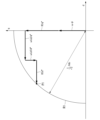
図3に示すフェーザ図は、電流指令値制限を行っていない動作点P1を示している。また、図4に示すフェーザ図は、図3の動作点P1から、設定された電圧余裕を持つ動作点となるように、q軸電流指令値Iq*を制限後q軸電流指令値Iq**に制限した場合の動作点P2を示している。図3及び図4に示す両図の比較から分かる通り、q軸電流指令値Iq*を制限後q軸電流指令値Iq**に制限することで、q軸電流指令値Iq*に係る項(ωLqIq*、RIq*)のベクトルが縮む。
The phasor diagram in Figure 3 shows an operating point P1 where no current command value limiting is performed. The phasor diagram in Figure 4 shows an operating point P2 when the q-axis current command value Iq* is limited to the post-limiting q-axis current command value Iq** so that the operating point is moved from the operating point P1 in Figure 3 to an operating point with a set voltage margin. As can be seen from a comparison of Figures 3 and 4, by limiting the q-axis current command value Iq* to the post-limiting q-axis current command value Iq**, the vector of the term (ωLqIq*, RIq*) related to the q-axis current command value Iq* shrinks.
このように、本実施形態におけるモータ制御装置1では、q軸電流指令値Iq*を制限後q軸電流指令値Iq**に制限することで動作点を動作点P1から動作点P2に変更することができ、設置された電圧余裕を持つ動作点にすることが可能である。
In this way, in the motor control device 1 of this embodiment, the operating point can be changed from operating point P1 to operating point P2 by limiting the q-axis current command value Iq* to the post-limitation q-axis current command value Iq**, making it possible to set the operating point to one with a set voltage margin.
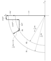
また、図5及び図6は、本実施形態におけるモータ制御装置1の動作の別の一例を説明する図である。図5及び図6は、既知のモータの電圧方程式に基づいたフェーザ図を示しており、簡便な説明のために、軸毎に電流指令値制限を行った状態を仮定して説明する。
FIGS. 5 and 6 are diagrams illustrating another example of the operation of the motor control device 1 in this embodiment. FIGS. 5 and 6 show phasor diagrams based on a known motor voltage equation, and for ease of explanation, the explanation is given assuming that the current command value is limited for each axis.
図5に示すフェーザ図は、電流指令値制限を行っていない動作点P3を示している。また、図6に示すフェーザ図は、図5に示す動作点P3から、設定された電圧余裕を持つ動作点となるように、d軸電流指令値Id*を制限後d軸電流指令値Id**に制限した場合の動作点P4を示している。図5及び図6に示す両図の比較から分かる通り、d軸電流指令値Id*を制限後d軸電流指令値Id**に制限することで、d軸電流指令値Id*に係る項(ωLdId*、RId*)のベクトルが伸びる。
The phasor diagram in Figure 5 shows an operating point P3 where no current command value limiting is performed. The phasor diagram in Figure 6 shows an operating point P4 when the d-axis current command value Id* is limited to the post-limiting d-axis current command value Id** so that the operating point has a set voltage margin from the operating point P3 shown in Figure 5. As can be seen from a comparison of Figures 5 and 6, by limiting the d-axis current command value Id* to the post-limiting d-axis current command value Id**, the vector of the term (ωLdId*, RId*) related to the d-axis current command value Id* is extended.
このように、本実施形態におけるモータ制御装置1では、d軸電流指令値Id*を制限後d軸電流指令値Id**に制限することで動作点を動作点P3から動作点P4に変更することができ、設定された電圧余裕を持つ動作点にすることが可能である。
In this way, in the motor control device 1 of this embodiment, the operating point can be changed from operating point P3 to operating point P4 by limiting the d-axis current command value Id* to the post-limitation d-axis current command value Id**, making it possible to set the operating point to one with a set voltage margin.
なお、本実施形態におけるモータ制御装置1では、上記のようにd軸及びq軸のどちらか一方だけでなく、d軸及びq軸の両軸に対して制限して動作点を変更してもよい。その場合、動作点の変更は上述した図4及び図6の複合となる。
In the motor control device 1 of this embodiment, the operating point may be changed by restricting it to both the d-axis and the q-axis, rather than just one of them as described above. In that case, the change in the operating point is a combination of the above-mentioned Figures 4 and 6.
以上説明したように、本実施形態によるモータ制御装置1は、ベクトル制御によってモータ10の通電を制御するモータ制御装置であって、電流指令値演算部7と、電流指令値制限部8と、制御器12とを備える。電流指令値演算部7は、モータ10の指令値(例えば、トルク指令T_ref)に基づいて、dq座標系の電流指令値(d軸電流指令値Id*及びq軸電流指令値Iq*)を生成する。電流指令値制限部8は、電流指令値演算部7が生成したdq座標系の電流指令値(d軸電流指令値Id*及びq軸電流指令値Iq*)を制限し、制限後のdq座標系の電流指令値である電流制限指令値(制限後d軸電流指令値Id**及び制限後q軸電流指令値Iq**)を出力する。制御器12は、電流制限指令値(制限後d軸電流指令値Id**及び制限後q軸電流指令値Iq**)に対するフィードバック制御によりモータ10への電圧指令値(電圧指令値Vd*及び電圧指令値Vq*)を演算する。電流指令値制限部8は、直流母線電圧Vdcと電圧指令値(電圧指令値Vd*及び電圧指令値Vq*)とに基づいて、dq座標系の電圧制限円R1に対して、設定された電圧余裕を持つ動作点となるように、dq座標系の電流指令値(d軸電流指令値Id*又は/及びq軸電流指令値Iq*)を制限する。
As described above, the motor control device 1 according to this embodiment is a motor control device that controls the energization of the motor 10 by vector control, and includes a current command value calculation unit 7, a current command value limiting unit 8, and a controller 12. The current command value calculation unit 7 generates current command values in the dq coordinate system (d-axis current command value Id* and q-axis current command value Iq*) based on a command value for the motor 10 (e.g., torque command T_ref). The current command value limiting unit 8 limits the current command values in the dq coordinate system (d-axis current command value Id* and q-axis current command value Iq*) generated by the current command value calculation unit 7, and outputs current limit command values (limited d-axis current command value Id** and limited q-axis current command value Iq**), which are the current command values in the dq coordinate system after the limiting. The controller 12 calculates the voltage command value (voltage command value Vd* and voltage command value Vq*) for the motor 10 by feedback control of the current limit command value (limited d-axis current command value Id** and limited q-axis current command value Iq**). The current command value limiting unit 8 limits the current command value (d-axis current command value Id* and/or q-axis current command value Iq*) in the dq coordinate system based on the DC bus voltage Vdc and the voltage command value (voltage command value Vd* and voltage command value Vq*) so that the operating point has a set voltage margin with respect to the voltage limit circle R1 in the dq coordinate system.
これにより、本実施形態によるモータ制御装置1は、電圧制限円R1に対して電圧余裕を持つ動作点となるように、電流指令値(d軸電流指令値Id*及びq軸電流指令値Iq*)を制限することで、動作点から電圧余裕の範囲内では電圧飽和は生じない。また、本実施形態によるモータ制御装置1は、制限した電流指令値近傍の動作点で何等かの電圧外乱が生じたとしても、従来技術にように、電圧ガード値以下となるような補正を行わず、電圧余裕としての振れ幅を確保する。そのため、本実施形態によるモータ制御装置1では、発生した電圧外乱を抑制できるような電圧指令値の形状を保つことができる。その結果、本実施形態によるモータ制御装置1は、電圧飽和だけでなく、制限した電流指令値近傍の動作点で何等かの電圧外乱が発生した場合でも、電圧外乱に伴うモータの異音及び振動を抑制することができる。
Therefore, the motor control device 1 according to this embodiment limits the current command values (d-axis current command value Id* and q-axis current command value Iq*) so that the operating point has a voltage margin with respect to the voltage limit circle R1, and therefore voltage saturation does not occur within the range of the voltage margin from the operating point. Furthermore, even if some voltage disturbance occurs at an operating point near the limited current command value, the motor control device 1 according to this embodiment does not perform correction to make the voltage below the voltage guard value as in the conventional technology, and ensures a swing range as a voltage margin. Therefore, the motor control device 1 according to this embodiment can maintain the shape of the voltage command value that can suppress the generated voltage disturbance. As a result, the motor control device 1 according to this embodiment can suppress not only voltage saturation, but also abnormal noise and vibration of the motor caused by the voltage disturbance, even if some voltage disturbance occurs at an operating point near the limited current command value.
また、本実施形態によるモータ制御装置1は、直流母線電圧Vdcを検出する直流母線電圧検出部6を備える。dq座標系の電流指令値には、d軸電流指令値Id*と、q軸電流指令値Iq*とが含まれる。電流指令値制限部8は、直流母線電圧検出部6が検出した直流母線電圧Vdcと電圧指令値(電圧指令値Vd*及び電圧指令値Vq*)とに基づいて、電圧制限円R1に対して電圧余裕を持つ動作点となるように、d軸電流指令値Id*とq軸電流指令値Iq*との少なくとも一方を制限する。
The motor control device 1 according to this embodiment also includes a DC bus voltage detection unit 6 that detects the DC bus voltage Vdc. The current command value in the dq coordinate system includes a d-axis current command value Id* and a q-axis current command value Iq*. The current command value limiting unit 8 limits at least one of the d-axis current command value Id* and the q-axis current command value Iq* based on the DC bus voltage Vdc detected by the DC bus voltage detection unit 6 and the voltage command values (voltage command value Vd* and voltage command value Vq*) so as to provide an operating point with a voltage margin relative to the voltage limit circle R1.
これにより、本実施形態によるモータ制御装置1は、直流母線電圧Vdcに基づいて、d軸電流指令値Id*とq軸電流指令値Iq*との少なくとも一方を制限するため、直流母線電圧Vdcが変化した場合に適切に対応して、電圧外乱に伴うモータの異音及び振動を抑制することができる。
As a result, the motor control device 1 according to this embodiment limits at least one of the d-axis current command value Id* and the q-axis current command value Iq* based on the DC bus voltage Vdc, so that it can respond appropriately when the DC bus voltage Vdc changes and suppress abnormal noise and vibration of the motor caused by voltage disturbances.
また、本実施形態では、制御器12は、電圧指令値として、dq座標系の電圧指令値(電圧指令値Vd*及び電圧指令値Vq*)を出力する。電流指令値制限部8は、直流母線電圧Vdc及び電圧余裕を示す値Kに基づいて算出した算出値と、dq座標系の電圧指令値(電圧指令値Vd*及び電圧指令値Vq*)が示す電圧ベクトルの大きさとの偏差ΔVdqに応じて、d軸電流指令値とq軸電流指令値との少なくとも一方を制限する。
In addition, in this embodiment, the controller 12 outputs voltage command values in the dq coordinate system (voltage command value Vd* and voltage command value Vq*) as voltage command values. The current command value limiting unit 8 limits at least one of the d-axis current command value and the q-axis current command value according to the deviation ΔVdq between the value calculated based on the DC bus voltage Vdc and the value K indicating the voltage margin, and the magnitude of the voltage vector indicated by the voltage command values in the dq coordinate system (voltage command value Vd* and voltage command value Vq*).
これにより、本実施形態によるモータ制御装置1は、電圧指令値として、dq座標系の電圧指令値(電圧指令値Vd*及び電圧指令値Vq*)を用いることで、簡易な手法により、電圧外乱に伴うモータの異音及び振動を抑制することができる。
As a result, the motor control device 1 according to this embodiment can suppress abnormal noise and vibration of the motor caused by voltage disturbances using a simple method by using voltage command values in the dq coordinate system (voltage command value Vd* and voltage command value Vq*) as the voltage command values.
また、本実施形態では、電流指令値制限部8は、偏差ΔVdqの積算値に応じて、d軸電流指令値とq軸電流指令値の少なくとも一方を制限する。
In addition, in this embodiment, the current command value limiting unit 8 limits at least one of the d-axis current command value and the q-axis current command value according to the integrated value of the deviation ΔVdq.
これにより、本実施形態によるモータ制御装置1は、積算値を用いた制限を行うことで、電流制限指令値(制限後d軸電流指令値Id**及び制限後q軸電流指令値Iq**)の急激な変化を抑制でき、モータ10の異音及び振動をより適切に抑制することができる。
As a result, the motor control device 1 according to this embodiment can suppress sudden changes in the current limit command value (post-limit d-axis current command value Id** and post-limit q-axis current command value Iq**) by limiting using the integrated value, and can more appropriately suppress abnormal noise and vibration of the motor 10.
また、本実施形態によるモータ制御装置1は、電圧余裕を可変に設定する電圧余裕演算部17(電圧余裕設定部)を備える。電流指令値制限部8は、電圧余裕演算部17が設定した電圧余裕に基づいて、dq座標系の電流指令値を制限する。
The motor control device 1 according to this embodiment also includes a voltage margin calculation unit 17 (voltage margin setting unit) that variably sets the voltage margin. The current command value limiting unit 8 limits the current command value in the dq coordinate system based on the voltage margin set by the voltage margin calculation unit 17.
これにより、本実施形態によるモータ制御装置1は、例えば、モータ10の動作状態に応じて、電圧余裕を可変に設定することで、モータ10の異音及び振動をより適切に抑制することができる。
As a result, the motor control device 1 according to this embodiment can more appropriately suppress abnormal noise and vibration of the motor 10, for example, by variably setting the voltage margin according to the operating state of the motor 10.
また、本実施形態では、電圧余裕は、直流母線電圧Vdcに基づいて設定される(上述した式(3)を参照)。
これにより、本実施形態によるモータ制御装置1は、電圧余裕が、直流母線電圧Vdcに基づいて設定されるため、直流母線電圧Vdcに応じて、電圧余裕を適切に変更して設定することができる。 Moreover, in this embodiment, the voltage margin is set based on the DC bus voltage Vdc (see the above-mentioned formula (3)).
As a result, in themotor control device 1 according to the present embodiment, the voltage margin is set based on the DC bus voltage Vdc, and therefore the voltage margin can be appropriately changed and set in accordance with the DC bus voltage Vdc.
これにより、本実施形態によるモータ制御装置1は、電圧余裕が、直流母線電圧Vdcに基づいて設定されるため、直流母線電圧Vdcに応じて、電圧余裕を適切に変更して設定することができる。 Moreover, in this embodiment, the voltage margin is set based on the DC bus voltage Vdc (see the above-mentioned formula (3)).
As a result, in the
[第2の実施形態]
次に、図面を参照して、第2の実施形態によるモータ制御装置1aについて説明する。 Second Embodiment
Next, amotor control device 1a according to a second embodiment will be described with reference to the drawings.
次に、図面を参照して、第2の実施形態によるモータ制御装置1aについて説明する。 Second Embodiment
Next, a
図7は、第2の実施形態によるモータ制御装置1aの一例を示すブロック図である。
図7に示すように、モータ制御装置1aは、モータ制御部110aと、モータ位置検出器2と、インバータ5とを備える。また、モータ制御部110aは、直流母線電圧検出部6と、電流指令値演算部7と、電流指令値制限部8aと、速度演算器9と、3相/2相座標変換器と、制御器12aと、電流検出器13と、PWM信号生成器16と、電圧余裕演算部17とを備える。 FIG. 7 is a block diagram showing an example of amotor control device 1a according to the second embodiment.
7, themotor control device 1a includes a motor control unit 110a, a motor position detector 2, and an inverter 5. The motor control unit 110a also includes a DC bus voltage detection unit 6, a current command value calculation unit 7, a current command value limiting unit 8a, a speed calculation unit 9, a three-phase/two-phase coordinate converter, a controller 12a, a current detector 13, a PWM signal generator 16, and a voltage margin calculation unit 17.
図7に示すように、モータ制御装置1aは、モータ制御部110aと、モータ位置検出器2と、インバータ5とを備える。また、モータ制御部110aは、直流母線電圧検出部6と、電流指令値演算部7と、電流指令値制限部8aと、速度演算器9と、3相/2相座標変換器と、制御器12aと、電流検出器13と、PWM信号生成器16と、電圧余裕演算部17とを備える。 FIG. 7 is a block diagram showing an example of a
7, the
本実施形態では、電流指令値制限部8aの処理が異なる点と、制御器12aが、2相/3相座標変換器14及び修正電圧生成器15aを含む点が、第1の実施形態と異なる。
なお、図7において、上述した図1と同一の構成には、同一の符号を付与して、その説明を省略する。 This embodiment differs from the first embodiment in that the processing of a current commandvalue limiting unit 8a is different, and that a controller 12a includes a two-phase/three-phase coordinate converter 14 and a corrected voltage generator 15a.
In FIG. 7, the same components as those in FIG. 1 are given the same reference numerals, and the description thereof will be omitted.
なお、図7において、上述した図1と同一の構成には、同一の符号を付与して、その説明を省略する。 This embodiment differs from the first embodiment in that the processing of a current command
In FIG. 7, the same components as those in FIG. 1 are given the same reference numerals, and the description thereof will be omitted.
制御器12aは、電圧指令値として、モータ10が有する3相巻線(U、V、W)の各相に対応した相電圧指令値を出力する。制御器12aは、相電圧指令値として、修正電圧指令値(u相修正電圧指令値vu’、v相修正電圧指令値vv’、w相修正電圧指令値vw’)を出力する。
The controller 12a outputs, as voltage command values, phase voltage command values corresponding to each phase of the three-phase windings (U, V, W) of the motor 10. The controller 12a outputs, as phase voltage command values, corrected voltage command values (u-phase corrected voltage command value vu', v-phase corrected voltage command value vv', w-phase corrected voltage command value vw').
また、制御器12aは、減算器121及び減算器123と、d軸制御器122と、q軸制御器124と、2相/3相座標変換器14と、修正電圧生成器15aとを備える。
The controller 12a also includes a subtractor 121, a subtractor 123, a d-axis controller 122, a q-axis controller 124, a two-phase/three-phase coordinate converter 14, and a correction voltage generator 15a.
修正電圧生成器15aは、2相/3相座標変換器14が出力したu相電圧指令値vu、v相電圧指令値vv、及びw相電圧指令値vwに対して、電圧利用率を(2/31/2)倍に改善できる変調方式への切替を目的とした、オフセット電圧Voffsetを、3相に等しく加算する。修正電圧生成器15aは、さらに、何等かの外乱電圧に対する補償電圧Vcompを3相に等しく加算して、修正電圧指令値(u相修正電圧指令値vu’、v相修正電圧指令値vv’、w相修正電圧指令値vw’)を生成する。
The corrected voltage generator 15a adds an offset voltage Voffset, aimed at switching to a modulation method that can improve the voltage utilization rate by (2/3 1/2 ) times, equally to the three phases to the u-phase voltage command value vu, v-phase voltage command value vv, and w-phase voltage command value vw output by the two-phase/three-phase coordinate converter 14. The corrected voltage generator 15a further adds a compensation voltage Vcomp for some disturbance voltage equally to the three phases to generate corrected voltage command values (u-phase corrected voltage command value vu', v-phase corrected voltage command value vv', and w-phase corrected voltage command value vw').
ここで、補償電圧Vcompは、例えば、デッドタイム補償電圧又は特定の次数成分の抑制を目的とした補償電圧などである。
修正電圧生成器15aは、生成した修正電圧指令値(u相修正電圧指令値vu’、v相修正電圧指令値vv’、w相修正電圧指令値vw’)をPWM信号生成器16に出力する。 Here, the compensation voltage Vcomp is, for example, a dead time compensation voltage or a compensation voltage intended to suppress a specific order component.
The correctedvoltage generator 15 a outputs the generated corrected voltage command values (u-phase corrected voltage command value vu′, v-phase corrected voltage command value vv′, and w-phase corrected voltage command value vw′) to the PWM signal generator 16 .
修正電圧生成器15aは、生成した修正電圧指令値(u相修正電圧指令値vu’、v相修正電圧指令値vv’、w相修正電圧指令値vw’)をPWM信号生成器16に出力する。 Here, the compensation voltage Vcomp is, for example, a dead time compensation voltage or a compensation voltage intended to suppress a specific order component.
The corrected
電流指令値制限部8aは、電流指令値演算部7が生成したdq座標系の電流指令値(d軸電流指令値Id*、又は/及び、q軸電流指令値Iq*)を制限し、制限後のdq座標系の電流指令値である電流制限指令値(制限後d軸電流指令値Id**、又は/及び、制限後q軸電流指令値Iq**)を出力する。電流指令値制限部8aは、例えば、直流母線電圧検出部6が検出した直流母線電圧Vdcと、電圧余裕演算部17が出力する電圧利用係数Kと、制御器12aより得られる修正電圧指令値(u相修正電圧指令値vu’、v相修正電圧指令値vv’、w相修正電圧指令値vw’)とに基づいて、dq座標系の電圧制限円R1に対して、設定された電圧余裕を持つ動作点となるように、dq座標系の電流指令値(制限後d軸電流指令値Id**、又は/及び、制限後q軸電流指令値Iq**)を制限する。
ここで、図8を参照して、電流指令値制限部8aの構成の詳細について説明する The current commandvalue limiting unit 8a limits the current command value in the dq coordinate system (d-axis current command value Id* or/and q-axis current command value Iq*) generated by the current command value calculation unit 7, and outputs a current limit command value (limited d-axis current command value Id** or/and limited q-axis current command value Iq**) which is the current command value in the dq coordinate system after the limiting. The current command value limiting unit 8a limits the current command value in the dq coordinate system (limited d-axis current command value Id** or/and limited q-axis current command value Iq**) based on, for example, the DC bus voltage Vdc detected by the DC bus voltage detection unit 6, the voltage utilization coefficient K output by the voltage margin calculation unit 17, and the corrected voltage command values (u-phase corrected voltage command value vu', v-phase corrected voltage command value vv', w-phase corrected voltage command value vw') obtained by the controller 12a, so as to become an operating point having a set voltage margin with respect to the voltage limit circle R1 in the dq coordinate system.
Here, the configuration of the current commandvalue limiting unit 8a will be described in detail with reference to FIG.
ここで、図8を参照して、電流指令値制限部8aの構成の詳細について説明する The current command
Here, the configuration of the current command
図8は、本実施形態における電流指令値制限部8aの一例を示すブロック図である。
図8に示すように、電流指令値制限部8aは、dq軸電圧演算器81aと、制限電圧演算器82と、減算器(83、85、86)と、積分演算器84と、電流指令値制限器87及び電流指令値制限器88とを備える。 FIG. 8 is a block diagram showing an example of the current commandvalue limiting unit 8a in this embodiment.
As shown in FIG. 8, the current commandvalue limiting unit 8 a includes a dq axis voltage calculator 81 a, a limit voltage calculator 82, subtractors (83, 85, 86), an integral calculator 84, a current command value limiter 87, and a current command value limiter 88.
図8に示すように、電流指令値制限部8aは、dq軸電圧演算器81aと、制限電圧演算器82と、減算器(83、85、86)と、積分演算器84と、電流指令値制限器87及び電流指令値制限器88とを備える。 FIG. 8 is a block diagram showing an example of the current command
As shown in FIG. 8, the current command
dq軸電圧演算器81aは、修正電圧指令値(u相修正電圧指令値vu’、v相修正電圧指令値vv’、w相修正電圧指令値vw’)から合成電圧ベクトルの大きさVdq*を演算する。なお、合成電圧ベクトルの大きさVdq*は、下記の式(7)で表される。
The dq-axis voltage calculator 81a calculates the magnitude Vdq* of the composite voltage vector from the corrected voltage command values (u-phase corrected voltage command value vu', v-phase corrected voltage command value vv', and w-phase corrected voltage command value vw'). The magnitude Vdq* of the composite voltage vector is expressed by the following equation (7).

すなわち、dq軸電圧演算器81aは、式(7)を用いて、合成電圧ベクトルの大きさVdq*を演算する。dq軸電圧演算器81aは、演算した合成電圧ベクトルの大きさVdq*を、減算器83に出力する。
その他の構成は、第1の実施形態の電流指令値制限部8と同様であるため、ここではその説明を省略する。 That is, the dq-axis voltage calculator 81a calculates the magnitude Vdq* of the composite voltage vector by using the equation (7). The dq-axis voltage calculator 81a outputs the calculated magnitude Vdq* of the composite voltage vector to the subtractor 83.
The other configuration is similar to that of the current commandvalue limiting unit 8 in the first embodiment, and therefore a description thereof will be omitted here.
その他の構成は、第1の実施形態の電流指令値制限部8と同様であるため、ここではその説明を省略する。 That is, the dq-
The other configuration is similar to that of the current command
以上説明したように、本実施形態では、制御器12aは、電圧指令値として、モータ10が有する3相巻線(U、V、W)の各相に対応した相電圧指令値(u相修正電圧指令値vu’、v相修正電圧指令値vv’、w相修正電圧指令値vw’)を出力する。電流指令値制限部8aは、直流母線電圧Vdc及び電圧余裕を示す値(電圧利用係数K)に基づいて算出した算出値と、各相に対応した相電圧指令値(u相修正電圧指令値vu’、v相修正電圧指令値vv’、w相修正電圧指令値vw’)に基づいて算出した各相間電圧の合成電圧ベクトルの大きさとの偏差ΔVdqとに応じて、d軸電流指令値Id*とq軸電流指令値Iq*との少なくとも一方を制限する。
As described above, in this embodiment, the controller 12a outputs, as voltage command values, phase voltage command values (u-phase corrected voltage command value vu', v-phase corrected voltage command value vv', w-phase corrected voltage command value vw') corresponding to each phase of the three-phase winding (U, V, W) of the motor 10. The current command value limiting unit 8a limits at least one of the d-axis current command value Id* and the q-axis current command value Iq* according to the deviation ΔVdq between a calculated value calculated based on the DC bus voltage Vdc and a value indicating the voltage margin (voltage utilization coefficient K) and the magnitude of the composite voltage vector of each interphase voltage calculated based on the phase voltage command values corresponding to each phase (u-phase corrected voltage command value vu', v-phase corrected voltage command value vv', w-phase corrected voltage command value vw').
これにより、本実施形態によるモータ制御装置1aは、電圧指令値として、各相の相電圧指令値(u相修正電圧指令値vu’、v相修正電圧指令値vv’、w相修正電圧指令値vw’)を用いることで、例えば、2相/3相座標変換後に、電圧外乱の発生又は補償電圧の印加がなされた場合であっても、これらを考慮した電流指令値制限を行うことができる。
As a result, the motor control device 1a according to this embodiment uses the phase voltage command values of each phase (u-phase corrected voltage command value vu', v-phase corrected voltage command value vv', w-phase corrected voltage command value vw') as the voltage command value, and can limit the current command value taking these into consideration, even if a voltage disturbance occurs or a compensation voltage is applied after, for example, two-phase/three-phase coordinate transformation.
[第3の実施形態]
次に、図面を参照して、第3の実施形態によるモータ制御装置1(1a)について説明する。本実施形態では、第1及び第2の実施形態のモータ制御装置1(1a)において、電圧余裕演算部17により演算される電圧利用係数Kを可変とした変形例について説明する。 [Third embodiment]
Next, a motor control device 1 (1a) according to a third embodiment will be described with reference to the drawings. In this embodiment, a modification of the motor control device 1 (1a) according to the first and second embodiments will be described in which the voltage utilization coefficient K calculated by the voltagemargin calculation unit 17 is made variable.
次に、図面を参照して、第3の実施形態によるモータ制御装置1(1a)について説明する。本実施形態では、第1及び第2の実施形態のモータ制御装置1(1a)において、電圧余裕演算部17により演算される電圧利用係数Kを可変とした変形例について説明する。 [Third embodiment]
Next, a motor control device 1 (1a) according to a third embodiment will be described with reference to the drawings. In this embodiment, a modification of the motor control device 1 (1a) according to the first and second embodiments will be described in which the voltage utilization coefficient K calculated by the voltage
図9は、第3の実施形態におけるモータ制御装置1(1a)の動作を説明する図である。
図9において、波形W1は、直流母線電圧Vdcの変化を示し、波形W2は、電圧利用係数Kの変化を示している。なお、各グラフの横軸は、時間を示している。 FIG. 9 is a diagram illustrating the operation of the motor control device 1 (1a) in the third embodiment.
9, a waveform W1 indicates a change in the DC bus voltage Vdc, and a waveform W2 indicates a change in the voltage utilization coefficient K. The horizontal axis of each graph indicates time.
本実施形態における電圧余裕演算部17は、図9に示すように、直流母線電圧Vdcに基づいて、電圧余裕を示す値(電圧利用係数K)を変更する。
例えば、図9の時刻t1において、直流母線電圧Vdcが異常判定値Vabを下回った場合(異常判定値Vab以下になった場合)に、電圧余裕演算部17は、電圧利用係数Kを、予め設定された特定の値K1から、“1.0”に滑らかに変更する。 As shown in FIG. 9, the voltagemargin calculation unit 17 in this embodiment changes the value indicating the voltage margin (voltage utilization coefficient K) based on the DC bus voltage Vdc.
For example, at time t1 in FIG. 9 , when the DC bus voltage Vdc falls below the abnormality determination value Vab (becomes equal to or less than the abnormality determination value Vab), the voltagemargin calculation unit 17 smoothly changes the voltage utilization coefficient K from a predetermined specific value K1 to “1.0”.
例えば、図9の時刻t1において、直流母線電圧Vdcが異常判定値Vabを下回った場合(異常判定値Vab以下になった場合)に、電圧余裕演算部17は、電圧利用係数Kを、予め設定された特定の値K1から、“1.0”に滑らかに変更する。 As shown in FIG. 9, the voltage
For example, at time t1 in FIG. 9 , when the DC bus voltage Vdc falls below the abnormality determination value Vab (becomes equal to or less than the abnormality determination value Vab), the voltage
なお、電圧余裕演算部17は、電圧利用係数Kを変更させる際に、電圧余裕(電圧利用係数K)を滑らかに変化させるように、移行期間を設けて電圧余裕(電圧利用係数K)を変更して、滑らかに変更する。
When changing the voltage utilization coefficient K, the voltage margin calculation unit 17 changes the voltage margin (voltage utilization coefficient K) by setting a transition period so as to smoothly change the voltage margin (voltage utilization coefficient K), thereby making a smooth change.
ここで、「滑らか」とは、“0”か“1”といった離散的な値を取るということではなく、例えば、“0”から“1”の間を連続的に変化するということを表している。
Here, "smooth" does not mean taking discrete values such as "0" or "1", but rather means, for example, that it changes continuously between "0" and "1".
また、図9の時刻t2において、直流母線電圧Vdcが異常判定値Vabを超えた場合に、電圧余裕演算部17は、電圧利用係数Kを、“1.0”から、予め設定された特定の値K1に滑らかに変更する。
Furthermore, at time t2 in FIG. 9, when the DC bus voltage Vdc exceeds the abnormality determination value Vab, the voltage margin calculation unit 17 smoothly changes the voltage utilization coefficient K from "1.0" to a specific value K1 that is set in advance.
以上説明したように、本実施形態では、電圧余裕演算部17(電圧余裕設定部)は、直流母線電圧Vdcに基づいて、電圧余裕(電圧利用係数K)を変更する。
これにより、本実施形態によるモータ制御装置1(1a)は、直流母線電圧Vdcに応じて、適切に電圧余裕(電圧利用係数K)を変更することができる。例えば、直流母線電圧Vdcが低下して異常が検出された場合に、電圧余裕演算部17は、電圧利用係数Kを、“1.0”に変更することで、実質的に電流指令値制限部8(8a)の働きを無効化することができ、直流母線電圧Vdcが低下した場合であっても、モータ出力を確保することができる。 As described above, in this embodiment, the voltage margin calculation unit 17 (voltage margin setting unit) changes the voltage margin (voltage utilization coefficient K) based on the DC bus voltage Vdc.
As a result, the motor control device 1 (1a) according to this embodiment can appropriately change the voltage margin (voltage utilization coefficient K) in accordance with the DC bus voltage Vdc. For example, when the DC bus voltage Vdc drops and an abnormality is detected, the voltagemargin calculation unit 17 changes the voltage utilization coefficient K to "1.0", which can essentially disable the function of the current command value limiting unit 8 (8a). Therefore, even if the DC bus voltage Vdc drops, the motor output can be ensured.
これにより、本実施形態によるモータ制御装置1(1a)は、直流母線電圧Vdcに応じて、適切に電圧余裕(電圧利用係数K)を変更することができる。例えば、直流母線電圧Vdcが低下して異常が検出された場合に、電圧余裕演算部17は、電圧利用係数Kを、“1.0”に変更することで、実質的に電流指令値制限部8(8a)の働きを無効化することができ、直流母線電圧Vdcが低下した場合であっても、モータ出力を確保することができる。 As described above, in this embodiment, the voltage margin calculation unit 17 (voltage margin setting unit) changes the voltage margin (voltage utilization coefficient K) based on the DC bus voltage Vdc.
As a result, the motor control device 1 (1a) according to this embodiment can appropriately change the voltage margin (voltage utilization coefficient K) in accordance with the DC bus voltage Vdc. For example, when the DC bus voltage Vdc drops and an abnormality is detected, the voltage
また、本実施形態では、電圧余裕演算部17は、電圧余裕を滑らかに変化させるように、移行期間を設けて電圧余裕を変更する。
これにより、本実施形態によるモータ制御装置1(1a)は、電圧利用係数Kを滑らかに変化させることで、電流制限指令値(制限後d軸電流指令値Id**、及び制限後q軸電流指令値Iq**)の急変を抑制することができ、電圧利用係数Kの変更に伴うモータの異音及び振動を抑制することができる。 Moreover, in this embodiment, the voltagemargin calculation unit 17 changes the voltage margin by providing a transition period so as to smoothly change the voltage margin.
As a result, the motor control device 1 (1a) according to this embodiment can smoothly change the voltage utilization coefficient K, thereby suppressing sudden changes in the current limiting command values (the post-limiting d-axis current command value Id** and the post-limiting q-axis current command value Iq**), and can suppress abnormal noise and vibration of the motor that accompanies changes in the voltage utilization coefficient K.
これにより、本実施形態によるモータ制御装置1(1a)は、電圧利用係数Kを滑らかに変化させることで、電流制限指令値(制限後d軸電流指令値Id**、及び制限後q軸電流指令値Iq**)の急変を抑制することができ、電圧利用係数Kの変更に伴うモータの異音及び振動を抑制することができる。 Moreover, in this embodiment, the voltage
As a result, the motor control device 1 (1a) according to this embodiment can smoothly change the voltage utilization coefficient K, thereby suppressing sudden changes in the current limiting command values (the post-limiting d-axis current command value Id** and the post-limiting q-axis current command value Iq**), and can suppress abnormal noise and vibration of the motor that accompanies changes in the voltage utilization coefficient K.
[第4の実施形態]
次に、図面を参照して、第4の実施形態による電動パワーステアリング装置100について説明する。
図10は、第4の実施形態による電動パワーステアリング装置100の一例を示すブロック図である。 [Fourth embodiment]
Next, an electricpower steering device 100 according to a fourth embodiment will be described with reference to the drawings.
FIG. 10 is a block diagram showing an example of an electricpower steering device 100 according to the fourth embodiment.
次に、図面を参照して、第4の実施形態による電動パワーステアリング装置100について説明する。
図10は、第4の実施形態による電動パワーステアリング装置100の一例を示すブロック図である。 [Fourth embodiment]
Next, an electric
FIG. 10 is a block diagram showing an example of an electric
図10に示すように、電動パワーステアリング装置100は、モータ10と、ステアリングホイール101と、トルクセンサ102と、ステアリングシャフト103と、車輪104と、ラック・ピニオンギヤ105と、ギア106と、制御装置107とを備える。また、制御装置107は、上述したモータ制御装置1(1a)と、異常検出部108と、車速情報通信器109とを備えている。
As shown in FIG. 10, the electric power steering device 100 includes a motor 10, a steering wheel 101, a torque sensor 102, a steering shaft 103, wheels 104, a rack and pinion gear 105, a gear 106, and a control device 107. The control device 107 also includes the motor control device 1 (1a) described above, an abnormality detection unit 108, and a vehicle speed information communication device 109.
トルクセンサ102は、運転者(不図示)の操舵トルクを検出する。
車輪104は、例えば、自動車などの車両の操舵対象の車輪(例えば、前倫)である。
電動パワーステアリング装置100において、運転者からステアリングホイール101に加えられた操舵トルクは、トルクセンサ102のトーションバー、及びステアリングシャフト103を通り、ラック・ピニオンギヤ105を介してラックに伝達される。これにより、電動パワーステアリング装置100は、車輪104を転舵させる。
車速情報通信器109は、車両速度を計測し、モータ制御装置1(1a)に、ネットワークを経由して車両速度を通知する。 Thetorque sensor 102 detects the steering torque of a driver (not shown).
Thewheels 104 are, for example, wheels (for example, front wheels) that are to be steered of a vehicle such as an automobile.
In the electricpower steering device 100, steering torque applied to a steering wheel 101 by a driver passes through a torsion bar of a torque sensor 102 and a steering shaft 103, and is transmitted to a rack via a rack-and-pinion gear 105. As a result, the electric power steering device 100 steers wheels 104.
The vehicle speedinformation communication device 109 measures the vehicle speed, and notifies the motor control device 1 (1a) of the vehicle speed via the network.
車輪104は、例えば、自動車などの車両の操舵対象の車輪(例えば、前倫)である。
電動パワーステアリング装置100において、運転者からステアリングホイール101に加えられた操舵トルクは、トルクセンサ102のトーションバー、及びステアリングシャフト103を通り、ラック・ピニオンギヤ105を介してラックに伝達される。これにより、電動パワーステアリング装置100は、車輪104を転舵させる。
車速情報通信器109は、車両速度を計測し、モータ制御装置1(1a)に、ネットワークを経由して車両速度を通知する。 The
The
In the electric
The vehicle speed
また、モータ10は、制御装置107のモータ制御装置1(1a)によって駆動され、出力としてアシスト力を発生する。アシスト力は、ギア106を介して、ステアリングシャフト103に伝達され、操舵時に運転者が加える操舵トルクを軽減する。制御装置107は、アシスト力を調整するためのアシスト指令を、トルクセンサ102によって検出した運転者の操舵トルク及び車両速度に基づいて算出する。制御装置107は、例えば、アシスト指令を、運転者の操舵トルクに比例する値として算出する。さらに、制御装置107は、モータ10の指令値となるトルク指令として、アシスト指令を設定する。
The motor 10 is driven by the motor control device 1 (1a) of the control device 107, and generates an assist force as an output. The assist force is transmitted to the steering shaft 103 via the gear 106, and reduces the steering torque applied by the driver when steering. The control device 107 calculates an assist command for adjusting the assist force based on the driver's steering torque detected by the torque sensor 102 and the vehicle speed. For example, the control device 107 calculates the assist command as a value proportional to the driver's steering torque. Furthermore, the control device 107 sets the assist command as a torque command that becomes the command value for the motor 10.
異常検出部108は、電動パワーステアリング装置100(モータ10の制御)の異常を監視しており、何等かの機能障害を検出した場合に、モータ制御装置1(1a)に異常信号を出力し、異常時の制御処理を開始させる。
The abnormality detection unit 108 monitors the electric power steering device 100 (control of the motor 10) for abnormalities, and if any functional malfunction is detected, it outputs an abnormality signal to the motor control device 1 (1a) and starts control processing in the event of an abnormality.
なお、本実施形態における電圧余裕演算部17は、モータ10の制御に異常を検出した場合に、検出した異常に応じて、電圧余裕を変更する。例えば、電圧余裕演算部17は、異常検出部108が出力する異常信号を受信した場合に、電圧利用係数Kを、“1.0”に変更する。
In addition, in this embodiment, when the voltage margin calculation unit 17 detects an abnormality in the control of the motor 10, it changes the voltage margin in accordance with the detected abnormality. For example, when the voltage margin calculation unit 17 receives an abnormality signal output by the abnormality detection unit 108, it changes the voltage utilization coefficient K to "1.0".
また、本実施形態における電圧余裕演算部17は、モータ制御装置1(1a)が搭載された車両速度に応じて、電圧余裕を変更する。電圧余裕演算部17は、例えば、車速情報通信器109によって受信した車両速度が、予め定められた特定の車両速度を超える場合に、電圧利用係数Kを、“1.0”に変更する。また、電圧余裕演算部17は、例えば、車速情報通信器109によって受信した車両速度が、予め定められた特定の車両速度を超えない場合に、電圧利用係数Kを、特定値に変更する。
In addition, the voltage margin calculation unit 17 in this embodiment changes the voltage margin according to the speed of the vehicle in which the motor control device 1 (1a) is mounted. For example, when the vehicle speed received by the vehicle speed information communication device 109 exceeds a specific vehicle speed that has been determined in advance, the voltage margin calculation unit 17 changes the voltage utilization coefficient K to "1.0". For example, when the vehicle speed received by the vehicle speed information communication device 109 does not exceed a specific vehicle speed that has been determined in advance, the voltage margin calculation unit 17 changes the voltage utilization coefficient K to a specific value.
次に、図11を参照して、本実施形態による電動パワーステアリング装置100の動作について説明する。
Next, the operation of the electric power steering device 100 according to this embodiment will be described with reference to FIG. 11.
図11において、電動パワーステアリング装置100の電圧余裕演算部17の動作の一例について説明する。なお、図11に示す処理は、定期的に実行されるものとする。
In FIG. 11, an example of the operation of the voltage margin calculation unit 17 of the electric power steering device 100 is described. Note that the process shown in FIG. 11 is executed periodically.
図11において、本実施形態における電圧余裕演算部17は、まず、異常信号を検知したか否かを判定する(ステップS101)。電圧余裕演算部17は、異常検出部108が出力する異常信号を受信したか否かにより、異常信号を検知したか否かを判定する。電圧余裕演算部17は、異常信号を検知した場合(ステップS101:YES)に、処理をステップS103に進める。また、電圧余裕演算部17は、異常信号を検知していない場合(ステップS101:NO)に、処理をステップS102に進める。
In FIG. 11, the voltage margin calculation unit 17 in this embodiment first determines whether or not an abnormal signal has been detected (step S101). The voltage margin calculation unit 17 determines whether or not an abnormal signal has been detected based on whether or not an abnormal signal output by the abnormality detection unit 108 has been received. If the voltage margin calculation unit 17 detects an abnormal signal (step S101: YES), the process proceeds to step S103. If the voltage margin calculation unit 17 does not detect an abnormal signal (step S101: NO), the process proceeds to step S102.
ステップS102において、電圧余裕演算部17は、車両速度が、特定の車両速度を超えたか否かを判定する。電圧余裕演算部17は、例えば、車速情報通信器109から受信した車両速度が、特定の車両速度を超えたか否かを判定する。電圧余裕演算部17は、車両速度が、特定の車両速度を超えた場合(ステップS102:YES)に、処理をステップS103に進める。また、電圧余裕演算部17は、車両速度が、特定の車両速度を以下である場合(ステップS102:NO)に、処理をステップS104に進める。
In step S102, the voltage margin calculation unit 17 determines whether the vehicle speed exceeds a specific vehicle speed. For example, the voltage margin calculation unit 17 determines whether the vehicle speed received from the vehicle speed information communication device 109 exceeds a specific vehicle speed. If the vehicle speed exceeds the specific vehicle speed (step S102: YES), the voltage margin calculation unit 17 advances the process to step S103. If the vehicle speed is equal to or less than the specific vehicle speed (step S102: NO), the voltage margin calculation unit 17 advances the process to step S104.
ステップS103において、電圧余裕演算部17は、電圧利用係数Kを“1.0”に変更する(K=1.0)。ステップS103の処理後に、電圧余裕演算部17は、処理を終了する。
In step S103, the voltage margin calculation unit 17 changes the voltage utilization coefficient K to "1.0" (K = 1.0). After processing in step S103, the voltage margin calculation unit 17 ends the processing.
ステップS104において、電圧余裕演算部17は、電圧利用係数Kを特定値に変更する(K=特定値)。ステップS104の処理後に、電圧余裕演算部17は、処理を終了する。
In step S104, the voltage margin calculation unit 17 changes the voltage utilization coefficient K to a specific value (K = specific value). After processing in step S104, the voltage margin calculation unit 17 ends the processing.
以上説明したように、本実施形態による電動パワーステアリング装置100は、上記に記載のモータ制御装置1(1a)と、モータ10と、トルクセンサ102とを備える。モータ10は、ステアリングの操舵をアシストする。トルクセンサ102は、ステアリングの操舵トルクを検出する。モータ制御装置1(1a)は、トルクセンサ102が検出した操舵トルクに応じたステアリングのアシスト指令を、モータ10の指令値として、モータ10を制御する。
As described above, the electric power steering device 100 according to this embodiment includes the motor control device 1 (1a) described above, the motor 10, and the torque sensor 102. The motor 10 assists steering. The torque sensor 102 detects the steering torque of the steering. The motor control device 1 (1a) controls the motor 10 using a steering assist command corresponding to the steering torque detected by the torque sensor 102 as a command value for the motor 10.
これにより、本実施形態による電動パワーステアリング装置100は、モータ制御装置1(1a)と同様の効果を奏し、制限した電流指令値近傍の動作点で何等かの電圧外乱が発生した場合でも、電圧外乱に伴うモータの異音及び振動を抑制することができる。
As a result, the electric power steering device 100 according to this embodiment has the same effect as the motor control device 1 (1a), and can suppress abnormal noise and vibration of the motor caused by voltage disturbances even if some voltage disturbance occurs at an operating point near the limited current command value.
また、本実施形態では、電圧余裕演算部17は、モータ10の制御に異常を検出した場合に、検出した異常に応じて、電圧余裕(電圧利用係数K)を変更する。電圧余裕演算部17は、例えば、異常を検出した場合に、電圧利用係数Kを“1.0”に変更して、電圧余裕を変更する。
In addition, in this embodiment, when the voltage margin calculation unit 17 detects an abnormality in the control of the motor 10, it changes the voltage margin (voltage utilization coefficient K) in accordance with the detected abnormality. For example, when the voltage margin calculation unit 17 detects an abnormality, it changes the voltage margin by changing the voltage utilization coefficient K to "1.0".
これにより、本実施形態による電動パワーステアリング装置100(モータ制御装置1(1a))は、モータ10の制御に異常が発生した場合に、適切に対応することができる。電動パワーステアリング装置100(モータ制御装置1(1a))は、例えば、異常を検出した場合に、操舵トルクに応じたアシストトルクを可能な限り出力し続けるために、電圧利用係数Kを“1.0”に変更して、電流指令値制限を無効化することができる。これにより、本実施形態による電動パワーステアリング装置100は、何等かの機能障害によりモータ出力の低下を抑制し、異常が発生した場合でもモータ出力を確保することができる。
As a result, the electric power steering device 100 (motor control device 1 (1a)) according to this embodiment can respond appropriately when an abnormality occurs in the control of the motor 10. For example, when an abnormality is detected, the electric power steering device 100 (motor control device 1 (1a)) can change the voltage utilization coefficient K to "1.0" and disable the current command value limit in order to continue to output the assist torque according to the steering torque as much as possible. As a result, the electric power steering device 100 according to this embodiment can suppress a decrease in motor output due to some kind of functional failure and ensure motor output even when an abnormality occurs.
また、本実施形態では、電圧余裕演算部17は、モータ制御装置1(1a)が搭載された車両速度に応じて、電圧余裕を変更する。電圧余裕演算部17は、例えば、車両速度が、特定の車両速度を超えた場合に、電圧利用係数Kを“1.0”に変更して、電圧余裕を変更する。また、電圧余裕演算部17は、例えば、車両速度が、特定の車両速度以下である場合に、電圧利用係数Kを特定値(1.0未満の値)に変更して、電圧余裕を変更する。
In addition, in this embodiment, the voltage margin calculation unit 17 changes the voltage margin according to the speed of the vehicle on which the motor control device 1 (1a) is mounted. For example, when the vehicle speed exceeds a specific vehicle speed, the voltage margin calculation unit 17 changes the voltage margin by changing the voltage utilization coefficient K to "1.0". For example, when the vehicle speed is equal to or lower than a specific vehicle speed, the voltage margin calculation unit 17 changes the voltage margin by changing the voltage utilization coefficient K to a specific value (a value less than 1.0).
これにより、本実施形態による電動パワーステアリング装置100(モータ制御装置1(1a))は、電圧利用係数Kを変更して、電圧余裕を確保することで、モータ10の異音及び振動をも抑制することができる。例えば、本実施形態による電動パワーステアリング装置100(モータ制御装置1(1a))は、高速で車両走行中、つまり、車速速度が高い場合に、緊急回避することができるように、モータ出力を最大限発揮できるように、電圧余裕をなくすように、電圧利用係数Kを変更することで、モータ出力を確保することができる。
As a result, the electric power steering device 100 (motor control device 1 (1a)) according to this embodiment can also suppress abnormal noise and vibration of the motor 10 by changing the voltage utilization coefficient K to ensure a voltage margin. For example, when the vehicle is traveling at high speed, that is, when the vehicle speed is high, the electric power steering device 100 (motor control device 1 (1a)) according to this embodiment can ensure motor output by changing the voltage utilization coefficient K to eliminate the voltage margin and maximize the motor output so as to enable emergency avoidance.
なお、本開示は、上記の各実施形態に限定されるものではなく、本開示の趣旨を逸脱しない範囲で変更可能である。
上記の各実施形態は、それぞれ単独で実施されてもよいし、一部、又は前記を組み合わせて実施してもよい。 The present disclosure is not limited to the above-described embodiments, and can be modified without departing from the spirit and scope of the present disclosure.
The above-described embodiments may be implemented individually or in part or in combination.
上記の各実施形態において、積分演算器84を用いる例を説明したが、これに限定されるものではなく、積分演算器84の代わりに、比例演算器、微分演算器、等を用いてもよいし、比例演算器、積分演算器、及び微分演算器の少なくとも1つ以上の演算を行ってもよい。
In each of the above embodiments, an example using an integral calculator 84 has been described, but the present invention is not limited to this. Instead of the integral calculator 84, a proportional calculator, a differential calculator, etc. may be used, or at least one of the proportional calculator, integral calculator, and differential calculator may be used.
上記の第3の実施形態において、本実施の形態では直流母線電圧Vdcの異常用いる例を説明したが、これに限定されるものではなく、その他にモータ制御で用いられるパラメータより電圧利用係数Kを変更してもよい。
In the above third embodiment, an example was described in which an abnormality in the DC bus voltage Vdc was used, but this is not limited to this, and the voltage utilization coefficient K may also be changed based on other parameters used in motor control.
上記の第4の実施形態において、異常信号及び車両速度に基づいて、電圧利用係数Kを変更する例を説明したが、これに限定されるものではない。電圧利用係数Kは、例えば、その他の電動パワーステアリングで利用する信号、つまり、運転手の操舵状態、例えば、操舵トルクTs、モータ10の回転速度により算出した操舵速度、等に基づいて変更されてもよい。また、走行状態の例として、停止、並びに走行とする状態を用いたが、それら以外の走行状態、例えば、旋回状態を示すヨーレート、横加速度信号、等を用いてもよい。
In the fourth embodiment above, an example was described in which the voltage utilization coefficient K is changed based on the abnormality signal and the vehicle speed, but this is not limiting. The voltage utilization coefficient K may be changed based on, for example, other signals used in the electric power steering, that is, the driver's steering state, such as the steering torque Ts, the steering speed calculated from the rotation speed of the motor 10, etc. Also, although the stopped and driving states are used as examples of the driving state, other driving states, such as a yaw rate or lateral acceleration signal indicating a turning state, may also be used.
なお、上述したモータ制御装置1(1a)が備える各構成は、内部に、コンピュータシステムを有している。そして、上述したモータ制御装置1(1a)が備える各構成の機能を実現するためのプログラムをコンピュータに読み取り可能な記録媒体に記録して、この記録媒体に記録されたプログラムをコンピュータシステムに読み込ませ、実行することにより上述したモータ制御装置1(1a)が備える各構成における処理を行ってもよい。ここで、「記録媒体に記録されたプログラムをコンピュータシステムに読み込ませ、実行する」とは、コンピュータシステムにプログラムをインストールすることを含む。ここでいう「コンピュータシステム」とは、OS及び周辺機器等のハードウェアを含むものとする。
また、「コンピュータシステム」は、インターネット、WAN、LAN、及び専用回線等の通信回線を含むネットワークを介して接続された複数のコンピュータ装置を含んでもよい。また、「コンピュータに読み取り可能な記録媒体」とは、フレキシブルディスク、光磁気ディスク、ROM、CD-ROM等の可搬媒体、コンピュータシステムに内蔵されるハードディスク等の記憶装置のことをいう。このように、プログラムを記憶した記録媒体は、CD-ROM等の非一過性の記録媒体であってもよい。 Each component of the motor control device 1 (1a) described above has an internal computer system. A program for implementing the functions of each component of the motor control device 1 (1a) described above may be recorded on a computer-readable recording medium, and the program recorded on the recording medium may be read into a computer system and executed to perform processing in each component of the motor control device 1 (1a) described above. Here, "reading a program recorded on a recording medium into a computer system and executing it" includes installing the program into a computer system. The "computer system" referred to here includes hardware such as an OS and peripheral devices.
Furthermore, a "computer system" may include a plurality of computer devices connected via a network including communication lines such as the Internet, WAN, LAN, and dedicated lines. Furthermore, a "computer-readable recording medium" refers to portable media such as flexible disks, optical magnetic disks, ROMs, and CD-ROMs, and storage devices such as hard disks built into a computer system. In this way, the recording medium storing the program may be a non-transitory recording medium such as a CD-ROM.
また、記録媒体には、当該プログラムを配信するために配信サーバからアクセス可能な内部又は外部に設けられた記録媒体も含まれる。なお、プログラムを複数に分割し、それぞれ異なるタイミングでダウンロードした後にモータ制御装置1(1a)が備える各構成で合体される構成、又は分割されたプログラムのそれぞれを配信する配信サーバが異なっていてもよい。さらに「コンピュータに読み取り可能な記録媒体」とは、ネットワークを介してプログラムが送信された場合のサーバ又はクライアントとなるコンピュータシステム内部の揮発性メモリ(RAM)のように、一定時間プログラムを保持しているものも含むものとする。また、上記プログラムは、上述した機能の一部を実現するためのものであってもよい。さらに、上述した機能をコンピュータシステムに既に記録されているプログラムとの組み合わせで実現できるもの、いわゆる差分ファイル(差分プログラム)であってもよい。
The recording medium also includes an internal or external recording medium accessible from a distribution server to distribute the program. The program may be divided into multiple parts, downloaded at different times, and then combined in each component of the motor control device 1 (1a), or each divided program may be distributed by a different distribution server. Furthermore, the term "computer-readable recording medium" also includes a recording medium that holds a program for a certain period of time, such as a volatile memory (RAM) inside a computer system that becomes a server or client when a program is transmitted over a network. The program may also be a recording medium for implementing part of the above-mentioned functions. Furthermore, the program may be a so-called difference file (difference program) that can realize the above-mentioned functions in combination with a program already recorded in the computer system.
1,1a…モータ制御装置、2…モータ位置検出器、3…直流電源、5…インバータ、6…直流母線電圧検出部、7…電流指令値演算部、8,8a…電流指令値制限部、9…速度演算器、10…モータ、11…3相/2相座標変換器、12,12a…制御器、13…電流検出器、14…2相/3相変換器、15,15a…修正電圧生成器、16…PWM信号生成器、17…電圧余裕演算器、41,42,43…シャント抵抗、51,52,53,54,55,56…スイッチング素子、81,81a…dq軸電圧演算器、82…制限電圧演算器、83,85,86,121,123…減算器、84…積分演算器、87,88…電流指令値制限器、100…電動パワーステアリング装置、101…ステアリングホイール、102…トルクセンサ、103…ステアリングシャフト、104…車輪、105…ラック・ピニオンギヤ、106…ギア、107…制御装置、108…異常検出部、109…車速情報通信器、110…モータ制御部、122…d軸制御器、124…q軸制御器、841,845…増幅器、842,846…加算器、843,847…電流制限器、844,848…遅延素子
1, 1a...motor control device, 2...motor position detector, 3...DC power supply, 5...inverter, 6...DC bus voltage detection unit, 7...current command value calculation unit, 8, 8a...current command value limiting unit, 9...speed calculator, 10...motor, 11...three-phase/two-phase coordinate converter, 12, 12a...controller, 13...current detector, 14...two-phase/three-phase converter, 15, 15a...corrected voltage generator, 16...PWM signal generator, 17...voltage margin calculator, 41, 42, 43...shunt resistor, 51, 52, 53, 54, 55, 56...switching element, 81, 81a...dq-axis voltage calculator, 82...limiting voltage calculator , 83, 85, 86, 121, 123... subtractor, 84... integral calculator, 87, 88... current command value limiter, 100... electric power steering device, 101... steering wheel, 102... torque sensor, 103... steering shaft, 104... wheel, 105... rack and pinion gear, 106... gear, 107... control device, 108... abnormality detection unit, 109... vehicle speed information communication device, 110... motor control unit, 122... d-axis controller, 124... q-axis controller, 841, 845... amplifier, 842, 846... adder, 843, 847... current limiter, 844, 848... delay element
Claims (11)
- ベクトル制御によってモータの通電を制御するモータ制御装置であって、
モータの指令値に基づいて、dq座標系の電流指令値を生成する電流指令値演算部と、
前記電流指令値演算部が生成した前記dq座標系の電流指令値を制限し、制限後の前記dq座標系の電流指令値である電流制限指令値を出力する電流指令値制限部と、
前記電流制限指令値に対するフィードバック制御により前記モータへの電圧指令値を演算する制御器と
を備え、
前記電流指令値制限部は、直流母線電圧と前記電圧指令値とに基づいて、dq座標系の電圧制限円に対して、設定された電圧余裕を持つ動作点となるように、前記dq座標系の電流指令値を制限する
モータ制御装置。 A motor control device that controls energization of a motor by vector control,
a current command value calculation unit that generates a current command value in a dq coordinate system based on a command value of the motor;
a current command value limiting unit that limits the current command value in the dq coordinate system generated by the current command value calculation unit and outputs a current limit command value that is the current command value in the dq coordinate system after the limiting;
a controller that calculates a voltage command value to the motor by feedback control of the current limit command value;
The motor control device, wherein the current command value limiting unit limits the current command value in a dq coordinate system based on a DC bus voltage and the voltage command value so as to result in an operating point having a set voltage margin with respect to a voltage limit circle in a dq coordinate system. - 前記直流母線電圧を検出する直流母線電圧検出部を備え、
前記dq座標系の電流指令値には、d軸電流指令値と、q軸電流指令値とが含まれ、
前記電流指令値制限部は、前記直流母線電圧検出部が検出した前記直流母線電圧と前記電圧指令値とに基づいて、前記電圧制限円に対して前記電圧余裕を持つ前記動作点となるように、前記d軸電流指令値と前記q軸電流指令値との少なくとも一方を制限する
請求項1に記載のモータ制御装置。 a DC bus voltage detection unit for detecting the DC bus voltage,
the current command value in the dq coordinate system includes a d-axis current command value and a q-axis current command value,
2. The motor control device according to claim 1, wherein the current command value limiting unit limits at least one of the d-axis current command value and the q-axis current command value so as to achieve the operating point having a voltage margin with respect to the voltage limit circle, based on the DC bus voltage detected by the DC bus voltage detection unit and the voltage command value. - 前記制御器は、前記電圧指令値として、dq座標系の電圧指令値を出力し、
前記電流指令値制限部は、前記直流母線電圧及び前記電圧余裕を示す値に基づいて算出した算出値と、前記dq座標系の電圧指令値が示す電圧ベクトルの大きさとの偏差に応じて、前記d軸電流指令値と前記q軸電流指令値との少なくとも一方を制限する
請求項2に記載のモータ制御装置。 The controller outputs a voltage command value in a dq coordinate system as the voltage command value,
3. The motor control device according to claim 2, wherein the current command value limiting unit limits at least one of the d-axis current command value and the q-axis current command value in accordance with a deviation between a value calculated based on the DC bus voltage and a value indicating the voltage margin, and a magnitude of a voltage vector indicated by a voltage command value in the dq coordinate system. - 前記制御器は、前記電圧指令値として、前記モータが有する3相の各相に対応した相電圧指令値を出力し、
前記電流指令値制限部は、前記直流母線電圧及び前記電圧余裕を示す値に基づいて算出した算出値と、前記各相に対応した前記相電圧指令値に基づいて算出した前記各相間電圧の合成電圧ベクトルの大きさとの偏差とに応じて、前記d軸電流指令値と前記q軸電流指令値との少なくとも一方を制限する
請求項2に記載のモータ制御装置。 the controller outputs, as the voltage command value, a phase voltage command value corresponding to each of three phases of the motor;
3. The motor control device according to claim 2, wherein the current command value limiting unit limits at least one of the d-axis current command value and the q-axis current command value in accordance with a deviation between a value calculated based on the DC bus voltage and the value indicating the voltage margin and a magnitude of a composite voltage vector of the inter-phase voltages calculated based on the phase voltage command values corresponding to each of the phases. - 前記電流指令値制限部は、前記偏差の積算値に応じて、前記d軸電流指令値と前記q軸電流指令値の少なくとも一方を制限する
請求項3又は請求項4に記載のモータ制御装置。 The motor control device according to claim 3 or 4, wherein the current command value limiting unit limits at least one of the d-axis current command value and the q-axis current command value in accordance with an integrated value of the deviation. - 前記電圧余裕を可変に設定する電圧余裕設定部を備え、
前記電流指令値制限部は、前記電圧余裕設定部が設定した前記電圧余裕に基づいて、前記dq座標系の電流指令値を制限する
請求項1から請求項5のいずれか一項に記載のモータ制御装置。 a voltage margin setting unit that variably sets the voltage margin,
The motor control device according to claim 1 , wherein the current command value limiting unit limits the current command value in the dq coordinate system based on the voltage margin set by the voltage margin setting unit. - 前記電圧余裕設定部は、前記電圧余裕を滑らかに変化させるように、移行期間を設けて前記電圧余裕を変更する
請求項6に記載のモータ制御装置。 The motor control device according to claim 6 , wherein the voltage margin setting unit changes the voltage margin by providing a transition period so as to smoothly change the voltage margin. - 前記電圧余裕設定部は、前記モータの制御に異常を検出した場合に、検出した前記異常に応じて、前記電圧余裕を変更する
請求項6又は請求項7に記載のモータ制御装置。 The motor control device according to claim 6 or 7, wherein the voltage margin setting unit is configured to, when detecting an abnormality in control of the motor, change the voltage margin in accordance with the detected abnormality. - 前記電圧余裕設定部は、前記モータ制御装置が搭載された車両速度に応じて、前記電圧余裕を変更する
請求項6から請求項8のいずれか一項に記載のモータ制御装置。 The motor control device according to claim 6 , wherein the voltage margin setting unit changes the voltage margin in accordance with a speed of a vehicle on which the motor control device is mounted. - 前記電圧余裕は、直流母線電圧に基づいて設定される
請求項1から請求項9のいずれか一項に記載のモータ制御装置。 The motor control device according to claim 1 , wherein the voltage margin is set based on a DC bus voltage. - 請求項1から請求項10のいずれか一項に記載のモータ制御装置と、
ステアリングの操舵をアシストする前記モータと、
前記ステアリングの操舵トルクを検出するトルクセンサと
を備え、
前記モータ制御装置は、前記トルクセンサが検出した前記操舵トルクに応じた前記ステアリングのアシスト指令を、前記モータの指令値として、前記モータを制御する
電動パワーステアリング装置。 A motor control device according to any one of claims 1 to 10;
The motor assists steering of the steering wheel;
a torque sensor for detecting a steering torque of the steering wheel,
The motor control device controls the motor using the steering assist command corresponding to the steering torque detected by the torque sensor as a command value for the motor.
Priority Applications (1)
| Application Number | Priority Date | Filing Date | Title |
|---|---|---|---|
| PCT/JP2022/039025 WO2024084639A1 (en) | 2022-10-20 | 2022-10-20 | Motor control device and electric power steering device |
Applications Claiming Priority (1)
| Application Number | Priority Date | Filing Date | Title |
|---|---|---|---|
| PCT/JP2022/039025 WO2024084639A1 (en) | 2022-10-20 | 2022-10-20 | Motor control device and electric power steering device |
Publications (1)
| Publication Number | Publication Date |
|---|---|
| WO2024084639A1 true WO2024084639A1 (en) | 2024-04-25 |
Family
ID=90737194
Family Applications (1)
| Application Number | Title | Priority Date | Filing Date |
|---|---|---|---|
| PCT/JP2022/039025 WO2024084639A1 (en) | 2022-10-20 | 2022-10-20 | Motor control device and electric power steering device |
Country Status (1)
| Country | Link |
|---|---|
| WO (1) | WO2024084639A1 (en) |
Citations (4)
| Publication number | Priority date | Publication date | Assignee | Title |
|---|---|---|---|---|
| JPH08266099A (en) * | 1994-05-25 | 1996-10-11 | Matsushita Electric Ind Co Ltd | Controller for permanent-magnet synchronous motor |
| JP2001186790A (en) * | 1999-12-24 | 2001-07-06 | Mitsubishi Electric Corp | Electric power steering controller |
| JP2009213336A (en) * | 2008-03-06 | 2009-09-17 | Nissan Motor Co Ltd | Motor controller |
| WO2020234971A1 (en) * | 2019-05-20 | 2020-11-26 | 三菱電機株式会社 | Motor driving device, compressor driving device, and refrigeration cycle device |
-
2022
- 2022-10-20 WO PCT/JP2022/039025 patent/WO2024084639A1/en unknown
Patent Citations (4)
| Publication number | Priority date | Publication date | Assignee | Title |
|---|---|---|---|---|
| JPH08266099A (en) * | 1994-05-25 | 1996-10-11 | Matsushita Electric Ind Co Ltd | Controller for permanent-magnet synchronous motor |
| JP2001186790A (en) * | 1999-12-24 | 2001-07-06 | Mitsubishi Electric Corp | Electric power steering controller |
| JP2009213336A (en) * | 2008-03-06 | 2009-09-17 | Nissan Motor Co Ltd | Motor controller |
| WO2020234971A1 (en) * | 2019-05-20 | 2020-11-26 | 三菱電機株式会社 | Motor driving device, compressor driving device, and refrigeration cycle device |
Similar Documents
| Publication | Publication Date | Title |
|---|---|---|
| US10300940B2 (en) | Electric power steering apparatus | |
| US10532765B2 (en) | Control apparatus for three-phase rotary machine, and electric power steering apparatus | |
| CN110651425B (en) | Motor control device and electric power steering device equipped with same | |
| US7928675B2 (en) | Feedback control method and apparatus for electric motor | |
| US8710775B2 (en) | Electric power steering apparatus | |
| US10333440B2 (en) | Motor control apparatus and electric power steering system | |
| US9660565B2 (en) | Controller for controlling a motor | |
| CN110612663A (en) | Motor control device and electric power steering device equipped with same | |
| US11177752B2 (en) | Controller anti-windup for permanent magnet synchronous machines | |
| EP3683956B1 (en) | Motor control device, electric actuator product and electric power steering device | |
| JP4797565B2 (en) | Motor drive control device | |
| JP4816257B2 (en) | Motor control device | |
| EP3495235B1 (en) | Steering control unit | |
| JP5397664B2 (en) | Motor control device | |
| WO2024084639A1 (en) | Motor control device and electric power steering device | |
| JP5595436B2 (en) | Motor control device | |
| JP2012066728A (en) | Electric power steering device | |
| JP2019050684A (en) | Controller of power steering device | |
| JP5028813B2 (en) | Electric power steering apparatus and control apparatus therefor | |
| US20230412099A1 (en) | Motor control device and electric power steering device provided with same | |
| US10577014B2 (en) | Steering control apparatus | |
| US20220109386A1 (en) | Torque capability optimization under active limiting of regenerative current in synchronous motor drives | |
| JP2009081915A (en) | Motor controller | |
| US20190152516A1 (en) | Steering control unit | |
| JP5495019B2 (en) | Motor control device and vehicle steering device |