WO2024079897A1 - 証明装置、通信システム、証明方法、及びプログラム - Google Patents
証明装置、通信システム、証明方法、及びプログラム Download PDFInfo
- Publication number
- WO2024079897A1 WO2024079897A1 PCT/JP2022/038443 JP2022038443W WO2024079897A1 WO 2024079897 A1 WO2024079897 A1 WO 2024079897A1 JP 2022038443 W JP2022038443 W JP 2022038443W WO 2024079897 A1 WO2024079897 A1 WO 2024079897A1
- Authority
- WO
- WIPO (PCT)
- Prior art keywords
- software
- verification
- proof
- unit
- logical formula
- Prior art date
- Legal status (The legal status is an assumption and is not a legal conclusion. Google has not performed a legal analysis and makes no representation as to the accuracy of the status listed.)
- Ceased
Links
Images







Classifications
-
- G—PHYSICS
- G06—COMPUTING OR CALCULATING; COUNTING
- G06F—ELECTRIC DIGITAL DATA PROCESSING
- G06F21/00—Security arrangements for protecting computers, components thereof, programs or data against unauthorised activity
- G06F21/50—Monitoring users, programs or devices to maintain the integrity of platforms, e.g. of processors, firmware or operating systems
- G06F21/57—Certifying or maintaining trusted computer platforms, e.g. secure boots or power-downs, version controls, system software checks, secure updates or assessing vulnerabilities
Definitions
- This disclosure relates to technology for proving the safety of software.
- Non-Patent Document 1 A method has also been proposed in which software source code is analyzed to list the sources and destinations of data that use functions (APIs: Application Programming Interfaces) related to a series of input/output operations of the software, and the trends in the relationships between these are used to check whether the software has unexpected communication functions such as backdoors (Non-Patent Document 1).
- APIs Application Programming Interfaces
- the present invention was made in consideration of the above points, and aims to make it possible to verify whether software has unexpected communication functions, such as backdoors, set up even for unknown threats.
- the invention of claim 1 is a proof device for proving the safety of software, the proof device having an input unit for inputting the software, a labeling unit for determining whether each variable appearing in the software is secret information or public information and labeling the variables related to the secret information, a verification logical formula generation processing unit for generating a verification logical formula using the labels labeled by the labeling unit to the effect that "the software satisfies the safety requirements if the verification logical formula can be derived using a specified inference rule", a proof generation unit for generating a proof of the safety of the software if the verification logical formula can be derived using the specified inference rule, and a transmission unit for transmitting the software, the verification logical formula, and the proof to a verification device that verifies the proof.
- the present invention has the effect of making it possible to verify whether a developed program has an unexpected communication function, such as a backdoor, set up, even against unknown threats.
- FIG. 1 is an overall configuration diagram of a communication system according to an embodiment of the present invention.
- FIG. 2 is a diagram showing the electrical hardware configuration of a proving device and a verifying device according to the present embodiment.
- FIG. 2 is a functional configuration diagram of a proof device and a verification device according to the present embodiment. This is a diagram that defines the program to be proven.
- FIG. 1 is a diagram defining rules for generating a verification logical formula.
- FIG. 6 is a diagram showing an example of a verification logical formula generated from software using the generation rules of FIG. 5 .
- FIG. 1 is a diagram illustrating inference rules.
- 13 is a flowchart showing a process or operation executed by the certification device.
- 13 is a flowchart showing a process or operation executed by the verification device.
- PCC simultaneously distributes the source code of the software and the proof of this source code, allowing communication device vendor A, the developer of the software, to guarantee the specifications and safety of the software to communication device vendor B, the user of the software.
- a PCC framework is disclosed that verifies that the software does not have unexpected communication functions such as so-called backdoors.
- Fig. 1 is a diagram showing the overall configuration of a communication system according to the present embodiment.
- the communication system 1 of this embodiment is constructed with a proof device 3 that proves the safety of software, and a verification device 5 that verifies the proof.
- the proof device 3 is managed and used by a communications equipment vendor A.
- the verification device 5 is managed and used by a communications carrier B.
- the proof device 3 is a computer, and in FIG. 1, a notebook computer is shown as an example.
- the proof device 3 may be composed of a single computer or multiple computers. Since the proof device 3 may be constructed of multiple computers, the proof device may be referred to as a "development system.”
- the proof device 3 uses the PCC framework to generate a verification logical formula that indicates the property that "if this verification logical formula can be derived using inference rules, then the software satisfies the safety requirements," and generates a proof if this verification logical formula is correct based on the inference rules.
- the proof device 3 then transmits the software, verification logical formula, and proof data to the verification device 5 via a communication network such as the Internet.
- the form of communication may be either wireless or wired.
- the verification device 5 is a computer, and in FIG. 1, a notebook computer is shown as an example.
- the verification device 5 may be composed of a single computer or multiple computers. Since the verification device 5 may be constructed of multiple computers, the verification device may be referred to as a "verification system.”
- the verification device 5 receives the software, the verification logical formula, and the proof data from the proof device 3 via the communication network. The verification device 5 then verifies that the proof is correct, and obtains a guarantee of the safety of the software.
- Fig. 2 is a diagram showing the electrical hardware configuration of the proving device and the verification device.
- the certification device 3 is a computer that includes a CPU 301, a ROM 302, a RAM 303, an SSD 304, an external device connection I/F (Interface) 305, a network I/F 306, a display 307, an input device 308, a media I/F 309, and a bus line 310.
- CPU 301 controls the overall operation of certification device 3.
- ROM 302 stores programs used to drive CPU 301, such as IPL.
- RAM 303 is used as a work area for CPU 301.
- SSD304 reads and writes various data according to the control of CPU301. Note that a HDD (Hard Disk Drive) may be used instead of SSD304.
- HDD Hard Disk Drive
- the external device connection I/F 305 is an interface for connecting various external devices.
- the external devices include a display, a speaker, a keyboard, a mouse, a USB memory, and a printer.
- the network I/F 306 is an interface for data communication via a communication network.
- Display 307 is a type of display means such as liquid crystal or organic EL (Electro Luminescence) that displays various images.
- the input device 308 is a keyboard, pointing device, etc., and is a type of input means for selecting and executing various instructions, selecting a processing target, moving a cursor, etc. When the user uses a keyboard, the pointing device function may be turned off.
- the media I/F 309 controls the reading and writing (storing) of data from and to a recording medium 309m such as a flash memory.
- Recording media 309m includes DVDs and Blu-ray Discs (registered trademarks).
- the bus line 310 is an address bus, a data bus, etc., for electrically connecting each component such as the CPU 301 shown in FIG. 2.
- the verification device 5 has the same electrical configuration as the certification device 3, the reference numbers in the 300s are shown as reference numbers in the 500s in Figure 2, and the explanation of these is omitted.
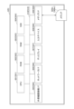
- Fig. 3 is a functional configuration diagram of the proving device and the verification device according to this embodiment.
- the proof device 3 has an input unit 31, a labeling unit 33, a verification condition generator unit 35, a proof generator unit 37, and a transmission unit 39. Each of these units is a function realized by an instruction from the CPU 301 in FIG. 2 based on a program.
- the verification condition generator unit 35 also has a lexical analysis unit 41, a syntax analysis unit 42, and a verification condition generator unit 43. Note that while a typical compiler performs lexical analysis, syntax analysis, and semantic analysis, and generates an executable file (binary), the verification condition generator unit 35 of this embodiment generates a verification condition instead of performing semantic analysis after lexical analysis and syntax analysis to generate an executable file.
- FIG. 5 defines the generation rules for a verification logical formula.
- FIG. 6 shows an example of a verification logical formula generated from software using the generation rules in FIG. 5.
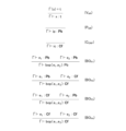
- FIG. 7 defines the inference rules.
- the input unit 31 inputs software obtained from the software developer.
- This software is the target for proving safety.
- an operation for calling a communication API is provided, and confidential information and public information are distinguished as constants.
- the software handled in this embodiment is defined by the contents shown in Figure 4.
- Figure 4 is a diagram that defines the program to be proven.
- the labeling unit 33 judges whether each variable appearing in the software (source code) input by the input unit 31 is secret information or public information, and labels the variables related to the secret information.
- the labeling unit 33 uses the idea of data flow analysis to define a certain tendency between the source and destination of data (ID, password, etc.) processed by the software.
- the labeling unit 33 labels data that is suspected to be secret information at the source of the data. Specifically, the labeling unit 33 distinguishes between secret information and non-secret information based on the directory name (e.g., /etc/ssl/certs or etc/ssl/private) in which the data processed by the software is stored.
- the lexical analysis unit 41 performs lexical analysis on the software source code input by the input unit 31, and replaces it with a token string, which is the smallest unit of a lexical string that has meaning in the language specification.
- the parser 42 analyzes the relationships between tokens in the token sequence passed from the lexical analyzer 41 according to the syntax rules of the language, and converts it into a data structure such as a parser tree.
- the verification logical formula generating unit 43 inputs the software converted into a data structure such as a syntax tree from the syntax analysis unit 42 and the requirements to be shown (for example, the software to be proved does not have unexpected communication functions such as a backdoor), generates generation rules (see FIG. 5) according to the requirements to be shown, and generates a verification logical formula using the generation rules and the labels applied by the labeling unit 33.
- the verification logical formula is a formula that indicates the property that "if (this verification logical formula) can be derived using a specified inference rule, the software satisfies the safety requirements.”
- the inference rules for the verification logical formula are shown in FIG. 5.
- the specified inference rules are rules for indicating which verification logical formula is correct (see FIG. 7).
- the verification logical formula generating unit 43 inputs the software shown in the above (Formula 1) and generates a verification logical formula as shown in FIG. 6.
- the verification logical formula generating unit 43 judges that if the encrypted communication API is called after obtaining confidential information, it is suspicious that an unexpected communication function is set, and generates a verification logical formula that reflects such an operation.
- the proof generating unit 37 inputs the verification logical formula from the verification logical formula generating unit 43, and generates a proof if the input verification logical formula is correct based on the inference rules (see FIG. 7).
- This proof generating unit 37 can be realized by, for example, the tool shown in Reference 1. ⁇ Reference 1> Colmerauer, A. and Roussel, P.: The birth of Prolog, HOPL-II, New York, NY, USA, Association for Computing Machinery, p. 37-52 (1993).
- This proof is a sequence of inference rules shown in Fig. 7. For example, as shown in Fig. 3, the proof indicates that "this software satisfies safety level a". Safety level a indicates, for example, that the software to be proven does not have an unexpected communication function such as a backdoor.
- the proof generating unit 37 will be described in detail below.
- a PCC that can verify the target safety requirements.
- types that represent public and private information are introduced for verification. The types are defined as follows:
- Pb denotes the type of public information
- Cf denotes the type of private information
- Rule V_AR indicates the typing rules within a type environment.
- Rule P_UB indicates that all public information has the type of public information.
- Rule C_ONF indicates that all private information has the type of private information.
- Rule BO_P1 indicates that the result of a binary operation between public information is public information.
- Rules BO_P2 and BO_P3 indicate that the result of a binary operation between public information and private information is private information.
- Rule BO_P4 indicates that the result of a binary operation between private information is private information.
- the transmission unit 39 transmits each piece of data to the verification device 5 via the communication network.
- the verification device 5 has a receiving unit 51, a proof verification unit 53, and an output unit 59. Each of these units is a function that is realized by instructions from the CPU 501 in FIG. 2 based on a program.
- the receiving unit 51 receives each piece of data sent from the certification device 3 via the communication network.
- the proof verification unit 53 inputs the software, verification logical formula, and proof data from the receiving unit 51, verifies the proof, and outputs the verification result of the proof.
- the verification result indicates True if the proof is correct, and False if it is incorrect.
- safety a indicates, for example, that the software to be proven (verified) does not have unexpected communication functions such as a backdoor.
- the proof verification unit 53 is similar to existing technology as disclosed in the above-mentioned Reference 1, etc., and therefore a detailed description thereof will be omitted.
- the output unit 59 outputs the data of the verification result of the proof. Examples of output include printing out the result on a printer or the like via the external device connection I/F 505, displaying the result on the display 507, or transmitting the result to the proof device 3 or another device via a communication network.
- the verification device 5 may have the same functionality as the verification logical formula generation processing unit 35 of the proof device 3. This allows the verification device 5 to confirm that the verification logical formula received from the proof device 3 corresponds to the software received together.
- Fig. 8 is a flowchart showing the process or operation executed by the certification device.
- the input unit 31 inputs the software (source code) obtained from the software developer.
- the labeling unit 33 labels each variable of the software input by the input unit 31 as public information or confidential information.
- the lexical analysis unit 41 performs lexical analysis on the source code of the software after labeling, and replaces it with a token string, which is the smallest unit of a lexical phrase that has meaning in the language specification.
- the syntax analysis unit 42 analyzes the relationships between tokens in the token string passed from the lexical analysis unit 41 according to the syntax rules of the language, and converts it into a data structure such as a syntax tree.
- S15 The software converted into a data structure such as a syntax tree from the syntax analysis unit 42 and the requirements to be displayed are input, and a verification logical formula is generated based on the generation rules (see Figure 5).
- the transmission unit 39 transmits to the verification device 5 each piece of data: the software (source code) input by the input unit 31, the verification logical formula generated by the verification logical formula generation processing unit 35, and the proof generated by the proof generation unit 37.
- Fig. 9 is a flowchart showing the process or operation executed by the verification device.
- the receiving unit 51 receives the software, verification logical formula, and proof data sent from the proof device 3 via the communication network.
- the output unit 59 outputs the data of the verification result of the proof.
- the software (program) of the communication device is analyzed by a technology related to formal verification and static code analysis called PCC, and the safety requirement that there is no unexpected communication function is expressed in the form of a verification logical formula.
- PCC a technology related to formal verification and static code analysis
- communication carriers can verify the safety of the software of the communication device and detect whether an unexpected communication function such as a backdoor is set. This has the effect of being able to detect whether an unexpected communication function such as a backdoor is set in a developed program even against unknown threats.
- the certification device 3 can guarantee the operation of the software itself by using the PCC.
- verifying a proof has a lower computational cost than creating the proof.
- telecommunications equipment vendor A including the software developer
- telecommunications carrier B including the software user
- the present invention is not limited to the above-described embodiment, and may have the following configurations or processes (operations).
- the certification device 3 and the verification device 5 can be realized by a computer and a program, but this program can also be recorded on a (non-temporary) recording medium or provided via a communication network such as the Internet.
- a notebook computer is shown as an example of the certification device 3 and the verification device 5, but this is not limited thereto, and the device may be, for example, a desktop computer, a tablet terminal, a smartphone, a smartwatch, etc.
- Each CPU 301, 501 may be multiple, not just single.
Landscapes
- Engineering & Computer Science (AREA)
- Computer Hardware Design (AREA)
- General Engineering & Computer Science (AREA)
- Computer Security & Cryptography (AREA)
- Software Systems (AREA)
- Theoretical Computer Science (AREA)
- Physics & Mathematics (AREA)
- General Physics & Mathematics (AREA)
- Storage Device Security (AREA)
Priority Applications (2)
| Application Number | Priority Date | Filing Date | Title |
|---|---|---|---|
| JP2024551034A JPWO2024079897A1 (https=) | 2022-10-14 | 2022-10-14 | |
| PCT/JP2022/038443 WO2024079897A1 (ja) | 2022-10-14 | 2022-10-14 | 証明装置、通信システム、証明方法、及びプログラム |
Applications Claiming Priority (1)
| Application Number | Priority Date | Filing Date | Title |
|---|---|---|---|
| PCT/JP2022/038443 WO2024079897A1 (ja) | 2022-10-14 | 2022-10-14 | 証明装置、通信システム、証明方法、及びプログラム |
Publications (1)
| Publication Number | Publication Date |
|---|---|
| WO2024079897A1 true WO2024079897A1 (ja) | 2024-04-18 |
Family
ID=90669317
Family Applications (1)
| Application Number | Title | Priority Date | Filing Date |
|---|---|---|---|
| PCT/JP2022/038443 Ceased WO2024079897A1 (ja) | 2022-10-14 | 2022-10-14 | 証明装置、通信システム、証明方法、及びプログラム |
Country Status (2)
| Country | Link |
|---|---|
| JP (1) | JPWO2024079897A1 (https=) |
| WO (1) | WO2024079897A1 (https=) |
Citations (4)
| Publication number | Priority date | Publication date | Assignee | Title |
|---|---|---|---|---|
| US5987252A (en) * | 1997-09-19 | 1999-11-16 | Digital Equipment Corporation | Method and apparatus for statically analyzing a computer program for data dependencies |
| US6128774A (en) * | 1997-10-28 | 2000-10-03 | Necula; George C. | Safe to execute verification of software |
| US20020112201A1 (en) * | 2000-12-04 | 2002-08-15 | Flanagan Cormac Andrias | Method and apparatus for automatically inferring annotations for an extended static checker |
| JP2010146299A (ja) * | 2008-12-18 | 2010-07-01 | Toshiba Corp | 情報処理装置、プログラム開発システム、プログラム検証方法及びプログラム |
-
2022
- 2022-10-14 WO PCT/JP2022/038443 patent/WO2024079897A1/ja not_active Ceased
- 2022-10-14 JP JP2024551034A patent/JPWO2024079897A1/ja active Pending
Patent Citations (4)
| Publication number | Priority date | Publication date | Assignee | Title |
|---|---|---|---|---|
| US5987252A (en) * | 1997-09-19 | 1999-11-16 | Digital Equipment Corporation | Method and apparatus for statically analyzing a computer program for data dependencies |
| US6128774A (en) * | 1997-10-28 | 2000-10-03 | Necula; George C. | Safe to execute verification of software |
| US20020112201A1 (en) * | 2000-12-04 | 2002-08-15 | Flanagan Cormac Andrias | Method and apparatus for automatically inferring annotations for an extended static checker |
| JP2010146299A (ja) * | 2008-12-18 | 2010-07-01 | Toshiba Corp | 情報処理装置、プログラム開発システム、プログラム検証方法及びプログラム |
Non-Patent Citations (5)
| Title |
|---|
| "Principles of Security and Trust", vol. 8414, 1 January 2014, SPRINGER BERLIN HEIDELBERG, Berlin, Heidelberg, ISBN: 978-3-642-54792-8, ISSN: 0302-9743, article DAVID COSTANZO: "A Separation Logic for Enforcing Declarative Information Flow Control Policies", pages: 179 - 198, XP093159517, DOI: 10.1007/978-3-642-54792-8_10 * |
| DENNIS VOLPANO: "A T ype-Based Approach to Program Security ?", LECTURES NOTES IN COMPUTER SCIENCE, vol. 1214, 1 April 1997 (1997-04-01), pages 607 - 621, XP093159532 * |
| LEE, SEONG-WHAN ; LI, STAN Z: "SAT 2015 18th International Conference, Austin, TX, USA, September 24-27, 2015", vol. 11187 Chap.23, 15 October 2018, SPRINGER , Berlin, Heidelberg , ISBN: 3540745491, article TöWS MANUEL; WEHRHEIM HEIKE: "Information Flow Certificates", pages: 435 - 454, XP047489900, 032548, DOI: 10.1007/978-3-030-02508-3_23 * |
| LENNART BERINGER: "Secure information flow and program logics", COMPUTER SECURITY FOUNDATIONS SYMPOSIUM, 2007. CSF '07. 20TH IEEE, IEEE, PI, 1 July 2007 (2007-07-01) - 8 July 2007 (2007-07-08), Pi , pages 233 - 248, XP093159525, ISBN: 978-0-7695-2819-9, DOI: 10.1109/CSF.2007.30 * |
| TSUBASA TOKOSHI ET AL.: "A method of securely executing programs using Proof-Carrying Code and TEE", IPSJ TECHNICAL REPORT, INFORMATION PROCESSING SOCIETY OF JAPAN, vol. 2022-CSEC-97, no. 7, 19 May 2022 (2022-05-19), pages 1 - 8, XP009554470 * |
Also Published As
| Publication number | Publication date |
|---|---|
| JPWO2024079897A1 (https=) | 2024-04-18 |
Similar Documents
| Publication | Publication Date | Title |
|---|---|---|
| US20240291863A1 (en) | Systems and Methods for Detecting Phishing-Based Cybersecurity Threats | |
| Sharma et al. | A survey of Mythril, a smart contract security analysis tool for EVM bytecode | |
| US20250036777A1 (en) | Generative cybersecurity exploit synthesis and mitigation | |
| US8776239B2 (en) | In-development vulnerability response management | |
| CN107431621B (zh) | 采用输入标记的可信二进制的二进制转换 | |
| Rubinov et al. | Automated partitioning of android applications for trusted execution environments | |
| CN103582888B (zh) | 在沙箱中保存引用的系统和方法 | |
| US9208319B2 (en) | Code base partitioning system | |
| US8701186B2 (en) | Formal analysis of the quality and conformance of information flow downgraders | |
| CN107466464A (zh) | 输入验证 | |
| CN107533622A (zh) | 可信二进制文件翻译 | |
| US12475235B2 (en) | Generative cybersecurity exploit discovery and evaluation | |
| KR20150122149A (ko) | 컴파일러 기반 난독화 기법 | |
| JP2007535761A (ja) | 抗タンパーコードを生成するシステム及び方法 | |
| US12288082B2 (en) | Automatic machine deployment and configuration | |
| US20250165618A1 (en) | Generative cybersecurity exploit discovery and evaluation | |
| Horne | Pwnpilot: Reflections on trusting trust in the age of large language models and AI code assistants | |
| Praveen | A comparative analysis of malware written in the C and rust programming languages | |
| US10565391B2 (en) | Expression evaluation of database statements for restricted data | |
| CN114756833A (zh) | 代码混淆方法、装置、设备、介质以及程序产品 | |
| WO2024079897A1 (ja) | 証明装置、通信システム、証明方法、及びプログラム | |
| US20060230292A1 (en) | Method, apparatus, and program to post process applications encrypting sensitive objects that are logged | |
| JP7355211B2 (ja) | シグネチャ生成装置、シグネチャ生成方法およびシグネチャ生成プログラム | |
| GB2559543A (en) | System and method for implementing and testing security protections in computer software | |
| CN114880667A (zh) | 一种脚本检测方法及装置 |
Legal Events
| Date | Code | Title | Description |
|---|---|---|---|
| 121 | Ep: the epo has been informed by wipo that ep was designated in this application |
Ref document number: 22962114 Country of ref document: EP Kind code of ref document: A1 |
|
| WWE | Wipo information: entry into national phase |
Ref document number: 2024551034 Country of ref document: JP |
|
| NENP | Non-entry into the national phase |
Ref country code: DE |
|
| 122 | Ep: pct application non-entry in european phase |
Ref document number: 22962114 Country of ref document: EP Kind code of ref document: A1 |