WO2024075318A1 - Coil switching system for vehicle motor, control device, method for controlling vehicle motor, and computer program - Google Patents
Coil switching system for vehicle motor, control device, method for controlling vehicle motor, and computer program Download PDFInfo
- Publication number
- WO2024075318A1 WO2024075318A1 PCT/JP2023/000923 JP2023000923W WO2024075318A1 WO 2024075318 A1 WO2024075318 A1 WO 2024075318A1 JP 2023000923 W JP2023000923 W JP 2023000923W WO 2024075318 A1 WO2024075318 A1 WO 2024075318A1
- Authority
- WO
- WIPO (PCT)
- Prior art keywords
- connection state
- motor
- current
- torque
- output
- Prior art date
Links
- 238000000034 method Methods 0.000 title claims description 43
- 238000004590 computer program Methods 0.000 title claims description 8
- 238000004804 winding Methods 0.000 claims description 313
- 230000008569 process Effects 0.000 claims description 36
- 230000007423 decrease Effects 0.000 claims description 23
- 230000001965 increasing effect Effects 0.000 claims description 15
- 230000001133 acceleration Effects 0.000 claims description 11
- 230000003247 decreasing effect Effects 0.000 claims description 9
- 230000008859 change Effects 0.000 abstract description 24
- 239000004065 semiconductor Substances 0.000 description 47
- 230000009467 reduction Effects 0.000 description 24
- 238000001514 detection method Methods 0.000 description 22
- 230000009347 mechanical transmission Effects 0.000 description 17
- 230000006870 function Effects 0.000 description 13
- 230000035807 sensation Effects 0.000 description 13
- 230000001172 regenerating effect Effects 0.000 description 12
- 238000010586 diagram Methods 0.000 description 10
- 238000012545 processing Methods 0.000 description 7
- 230000005540 biological transmission Effects 0.000 description 3
- 230000004044 response Effects 0.000 description 3
- 230000035939 shock Effects 0.000 description 3
- 238000013459 approach Methods 0.000 description 2
- 230000007935 neutral effect Effects 0.000 description 2
- 230000008929 regeneration Effects 0.000 description 2
- 238000011069 regeneration method Methods 0.000 description 2
- 230000007704 transition Effects 0.000 description 2
- HBBGRARXTFLTSG-UHFFFAOYSA-N Lithium ion Chemical compound [Li+] HBBGRARXTFLTSG-UHFFFAOYSA-N 0.000 description 1
- 238000004891 communication Methods 0.000 description 1
- 230000000694 effects Effects 0.000 description 1
- 230000005669 field effect Effects 0.000 description 1
- 230000001939 inductive effect Effects 0.000 description 1
- 229910001416 lithium ion Inorganic materials 0.000 description 1
- 229910044991 metal oxide Inorganic materials 0.000 description 1
- 150000004706 metal oxides Chemical class 0.000 description 1
- 238000012986 modification Methods 0.000 description 1
- 230000004048 modification Effects 0.000 description 1
- 230000001141 propulsive effect Effects 0.000 description 1
- 230000003068 static effect Effects 0.000 description 1
- 230000001360 synchronised effect Effects 0.000 description 1
Images


Classifications
-
- B—PERFORMING OPERATIONS; TRANSPORTING
- B60—VEHICLES IN GENERAL
- B60L—PROPULSION OF ELECTRICALLY-PROPELLED VEHICLES; SUPPLYING ELECTRIC POWER FOR AUXILIARY EQUIPMENT OF ELECTRICALLY-PROPELLED VEHICLES; ELECTRODYNAMIC BRAKE SYSTEMS FOR VEHICLES IN GENERAL; MAGNETIC SUSPENSION OR LEVITATION FOR VEHICLES; MONITORING OPERATING VARIABLES OF ELECTRICALLY-PROPELLED VEHICLES; ELECTRIC SAFETY DEVICES FOR ELECTRICALLY-PROPELLED VEHICLES
- B60L15/00—Methods, circuits, or devices for controlling the traction-motor speed of electrically-propelled vehicles
- B60L15/20—Methods, circuits, or devices for controlling the traction-motor speed of electrically-propelled vehicles for control of the vehicle or its driving motor to achieve a desired performance, e.g. speed, torque, programmed variation of speed
-
- B—PERFORMING OPERATIONS; TRANSPORTING
- B60—VEHICLES IN GENERAL
- B60L—PROPULSION OF ELECTRICALLY-PROPELLED VEHICLES; SUPPLYING ELECTRIC POWER FOR AUXILIARY EQUIPMENT OF ELECTRICALLY-PROPELLED VEHICLES; ELECTRODYNAMIC BRAKE SYSTEMS FOR VEHICLES IN GENERAL; MAGNETIC SUSPENSION OR LEVITATION FOR VEHICLES; MONITORING OPERATING VARIABLES OF ELECTRICALLY-PROPELLED VEHICLES; ELECTRIC SAFETY DEVICES FOR ELECTRICALLY-PROPELLED VEHICLES
- B60L50/00—Electric propulsion with power supplied within the vehicle
- B60L50/50—Electric propulsion with power supplied within the vehicle using propulsion power supplied by batteries or fuel cells
- B60L50/60—Electric propulsion with power supplied within the vehicle using propulsion power supplied by batteries or fuel cells using power supplied by batteries
-
- B—PERFORMING OPERATIONS; TRANSPORTING
- B60—VEHICLES IN GENERAL
- B60L—PROPULSION OF ELECTRICALLY-PROPELLED VEHICLES; SUPPLYING ELECTRIC POWER FOR AUXILIARY EQUIPMENT OF ELECTRICALLY-PROPELLED VEHICLES; ELECTRODYNAMIC BRAKE SYSTEMS FOR VEHICLES IN GENERAL; MAGNETIC SUSPENSION OR LEVITATION FOR VEHICLES; MONITORING OPERATING VARIABLES OF ELECTRICALLY-PROPELLED VEHICLES; ELECTRIC SAFETY DEVICES FOR ELECTRICALLY-PROPELLED VEHICLES
- B60L58/00—Methods or circuit arrangements for monitoring or controlling batteries or fuel cells, specially adapted for electric vehicles
- B60L58/10—Methods or circuit arrangements for monitoring or controlling batteries or fuel cells, specially adapted for electric vehicles for monitoring or controlling batteries
-
- B—PERFORMING OPERATIONS; TRANSPORTING
- B60—VEHICLES IN GENERAL
- B60L—PROPULSION OF ELECTRICALLY-PROPELLED VEHICLES; SUPPLYING ELECTRIC POWER FOR AUXILIARY EQUIPMENT OF ELECTRICALLY-PROPELLED VEHICLES; ELECTRODYNAMIC BRAKE SYSTEMS FOR VEHICLES IN GENERAL; MAGNETIC SUSPENSION OR LEVITATION FOR VEHICLES; MONITORING OPERATING VARIABLES OF ELECTRICALLY-PROPELLED VEHICLES; ELECTRIC SAFETY DEVICES FOR ELECTRICALLY-PROPELLED VEHICLES
- B60L9/00—Electric propulsion with power supply external to the vehicle
- B60L9/16—Electric propulsion with power supply external to the vehicle using ac induction motors
- B60L9/18—Electric propulsion with power supply external to the vehicle using ac induction motors fed from dc supply lines
-
- H—ELECTRICITY
- H02—GENERATION; CONVERSION OR DISTRIBUTION OF ELECTRIC POWER
- H02P—CONTROL OR REGULATION OF ELECTRIC MOTORS, ELECTRIC GENERATORS OR DYNAMO-ELECTRIC CONVERTERS; CONTROLLING TRANSFORMERS, REACTORS OR CHOKE COILS
- H02P25/00—Arrangements or methods for the control of AC motors characterised by the kind of AC motor or by structural details
- H02P25/16—Arrangements or methods for the control of AC motors characterised by the kind of AC motor or by structural details characterised by the circuit arrangement or by the kind of wiring
- H02P25/18—Arrangements or methods for the control of AC motors characterised by the kind of AC motor or by structural details characterised by the circuit arrangement or by the kind of wiring with arrangements for switching the windings, e.g. with mechanical switches or relays
Definitions
- This disclosure relates to a winding switching system for a vehicle motor, a control device, a control method for a vehicle motor, and a computer program.
- This application claims priority to Japanese Application No. 2022-162243, filed on October 7, 2022, and incorporates by reference all of the contents of said Japanese application.
- Patent Document 1 discloses that in vehicles that do not have stepped transmissions and in which the wheels are driven by a drive motor, such as electric vehicles and hybrid vehicles, a pseudo-shift change can be created by performing torque fluctuation control that reduces the torque of the drive motor by a set fluctuation amount and then increases it.
- a winding switching system for a vehicle motor includes a drive motor that drives the wheels of a vehicle, a control device that controls the drive motor, a power converter that converts DC power output from a battery into AC power and supplies the AC power to the drive motor, and a winding switching device that switches the connection state of a plurality of windings in the drive motor between a first connection state and a second connection state
- the control device includes a torque control unit that changes the output torque of the drive motor by changing the AC current output from the power converter at a predetermined shift timing of the vehicle, and a switching control unit that causes the winding switching device to switch from the first connection state to the second connection state after the AC current has changed.
- the present disclosure can be realized not only as a winding switching system for a vehicle motor having the above-mentioned characteristic configuration, but also as a control device included in the winding switching system for a vehicle motor, or as a control method for a vehicle motor having steps corresponding to characteristic processes in the control device.
- the present disclosure can be realized as a computer program that causes a computer to function as a control device, or as a semiconductor integrated circuit as a part or all of the control device.
- FIG. 1 is a diagram illustrating an example of the configuration of a winding switching system according to the first embodiment.
- FIG. 2 is a block diagram illustrating an example of a hardware configuration of the control device.
- FIG. 3 is a circuit diagram showing an example of the configuration of the winding switching device according to the first embodiment.
- FIG. 4 is a timing chart showing an example of timing for switching the windings of the motor in the winding switching system according to the first embodiment.
- FIG. 5 is a flowchart showing an example of an electrical up-shifting process performed by the control device according to the first embodiment.
- FIG. 6 is a flowchart showing an example of an electrical downshifting process performed by the control device according to the first embodiment.
- FIG. 1 is a diagram illustrating an example of the configuration of a winding switching system according to the first embodiment.
- FIG. 2 is a block diagram illustrating an example of a hardware configuration of the control device.
- FIG. 3 is a circuit diagram showing an example of the configuration of the winding switching
- FIG. 7 is a circuit diagram showing an example of the configuration of a winding switching device according to the second embodiment.
- FIG. 8 is a timing chart showing an example of timing for switching the windings of a motor in the winding switching system according to the third embodiment.
- FIG. 9 is a timing chart showing an example of timing for switching the windings of a motor in the winding switching system according to the fourth embodiment.
- FIG. 10 is a timing chart showing an example of a pseudo speed change control process in the winding switching system according to the fifth embodiment.
- FIG. 11 is a flowchart showing an example of a pseudo shifting process performed by the control device according to the fifth embodiment.
- FIG. 12 is a functional block diagram showing an example of functions of the control device according to the sixth embodiment.
- FIG. 13 is a flowchart showing an example of a forced up-shift determination process performed by the control device according to the sixth embodiment.
- FIG. 14 is a flowchart showing an example of a forced downshift determination process performed by the control device according to
- the winding switching system for a vehicle motor includes a drive motor that drives the wheels of a vehicle, a control device that controls the drive motor, a power converter that converts DC power output from a battery into AC power and supplies the AC power to the drive motor, and a winding switching device that switches the connection state of a plurality of windings in the drive motor between a first connection state and a second connection state.
- the control device includes a torque control unit that changes the output torque of the drive motor by changing the AC current output from the power converter at a predetermined shift timing of the vehicle, and a switching control unit that causes the winding switching device to switch from the first connection state to the second connection state after the AC current has changed.
- the torque control unit may reduce the output torque of the drive motor by reducing the AC current output from the power converter at a first shift timing, and the switching control unit may switch the winding switching device from the first connection state to the second connection state after the AC current has decreased to a first target value or less. This makes it possible to realize an electrical shift similar to an upshift by a mechanical transmission while the vehicle is accelerating or maintaining its speed.
- the torque control unit may reduce the output torque of the drive motor by reducing the AC current output from the power converter at a second shift timing different from the first shift timing, and the switching control unit may switch the winding switching device from the second connection state to the first connection state after the AC current has decreased to or below the first target value.
- the torque control unit may increase the output torque of the drive motor by increasing the AC current output from the power converter at the first shift timing, and the switching control unit may switch the winding switching device from the first connection state to the second connection state after the AC current has increased to or above a second target value. This makes it possible to realize an electrical shift similar to an upshift by a mechanical transmission while the drive motor is performing regenerative braking.
- the torque control unit may increase the output torque of the drive motor by increasing the AC current output from the power converter at a second shift timing different from the first shift timing, and the switching control unit may switch the winding switching device from the second connection state to the first connection state after the AC current has increased to or above a second target value.
- the second connection state may be a connection state in which the drive motor outputs a lower torque than the first connection state at the same rotation speed. This makes it possible to switch the connection state of the windings of the drive motor between the first connection state of a high-torque, low-speed type and the second connection state of a low-torque, high-speed type.
- control device may further include a first determination unit that determines, when the connection state of the plurality of windings is the first connection state, a timing before the induced voltage generated in the windings exceeds the output voltage of the battery as a first forced shift timing, and the torque control unit changes the output torque of the drive motor by changing the AC current output from the power converter at the first forced shift timing determined by the first determination unit, and the switching control unit may cause the winding switching device to switch from the first connection state to the second connection state after the AC current has changed.
- the induced voltage generated in the windings exceeds the output voltage of the battery, it is not possible to change the current flowing in the windings to zero.
- connection state of the windings is switched by the relay while a current is flowing in the windings, the relay may be damaged.
- the connection state of the windings is switched from the first connection state to the second connection state, the current flowing in the windings can be suppressed and the relay can be protected.
- the first determination unit may determine the timing at which the physical quantity related to the induced voltage exceeds a first threshold value corresponding to the output voltage of the battery as the first forced shift timing. This makes it possible to accurately determine the timing before the induced voltage exceeds the output voltage of the battery by using the physical quantity related to the induced voltage.
- the physical quantity may be one of the voltage in the winding, the rotation speed of the drive motor, the current flowing through the winding, and the output torque of the drive motor. This makes it possible to accurately determine the timing before the induced voltage exceeds the battery output voltage by one of the voltage in the winding, the rotation speed of the motor, the current flowing through the winding, and the output torque of the motor, which can be easily detected by a sensor.
- control device may further include a determination unit that, when the connection state of the plurality of windings is the second connection state, determines whether or not the induced voltage exceeds the output voltage of the battery after the connection state of the windings is switched from the second connection state to the first connection state, and a prohibition unit that prohibits the switching control unit from switching the connection state of the windings when the determination unit determines that the induced voltage exceeds the output voltage of the battery. This prevents the induced voltage of the windings from exceeding the output voltage of the battery after the connection state of the windings is switched from the second connection state to the first connection state. Therefore, the relay can be protected from damage.
- control device may further include a second determination unit that, when the connection state of the plurality of windings is the second connection state, determines the timing after the induced voltage becomes equal to or lower than the output voltage of the battery after the connection state of the windings is switched from the second connection state to the first connection state as the second forced shift timing, and the torque control unit changes the output torque of the drive motor by changing the AC current output from the power converter at the second forced shift timing determined by the second determination unit, and the switching control unit may cause the winding switching device to switch from the second connection state to the first connection state after the AC current has changed. This prevents the induced voltage of the winding from exceeding the output voltage of the battery after the connection state of the windings is switched from the second connection state to the first connection state.
- the relay can be protected from damage.
- the second determination unit may determine, as the second forced shift timing, the timing at which the physical quantity related to the induced voltage becomes equal to or lower than a second threshold value corresponding to the output voltage of the battery. This makes it possible to accurately determine the timing after the induced voltage becomes equal to or lower than the output voltage of the battery, using the physical quantity related to the induced voltage.
- the winding switching system may further include an input device that receives a gear shift instruction from a driver, and the gear shift timing may be the timing at which the input device receives the gear shift instruction from the driver. This allows the drive motor to perform electrical gear shifting in accordance with the driver's gear shift instruction.
- the shift timing may be determined based on the rotation speed of the drive motor, the output torque, the acceleration command amount for the vehicle, and the braking command amount for the vehicle. This allows the drive motor to perform electrical shifting according to the timing determined by the motor rotation speed, the output torque, the acceleration command amount (the amount of depression of the accelerator pedal), and the braking command amount (the amount of depression of the brake pedal).
- the torque control unit may gradually decrease or increase the effective current of the AC current output from the power converter from the shift timing. This allows the torque to be changed smoothly, providing the driver with a natural shift feeling.
- the torque control unit may change the effective current in a ramp shape from the shift timing. This allows the driver to feel a smooth shift in torque.
- the torque control unit may change the effective current of the AC current output from the power converter in a stepwise manner based on the shift timing. This allows the driver to feel a sudden change in torque when shifting.
- the torque control unit may execute a pseudo-shift control process to decrease and then increase the AC current output from the power converter at a pseudo-shift timing different from the shift timing. This causes the drive motor to execute a pseudo-shift in addition to the electrical shift. This allows the driver to feel a multi-stage shift.
- the control device is a control device for controlling a drive motor that drives the wheels of a vehicle, and includes a torque control unit that changes the output torque of the drive motor by converting DC power output from a battery into AC power and changing the AC current output from a power converter that supplies the AC power to the drive motor at a predetermined shift timing of the vehicle, and a switching control unit that switches the connection state of a plurality of windings in the drive motor from a first connection state to a second connection state after the AC current has changed.
- the connection state of the windings of the drive motor is switched from the first connection state to the second connection state, so that electrical shifting can be achieved by efficiently utilizing the performance of the drive motor.
- the driver can be given a shifting sensation similar to that of a mechanical transmission.
- the method for controlling a vehicle motor is a method for controlling a vehicle motor executed by a control device that controls a drive motor that drives the wheels of the vehicle, and includes the steps of: changing the output torque of the drive motor by converting DC power output from a battery into AC power and changing the AC current output from a power converter that supplies the AC power to the drive motor at a predetermined shift timing of the vehicle; and causing a winding switching device that switches the connection state of a plurality of windings in the drive motor to switch from a first connection state to a second connection state after the AC current has changed.
- the computer program according to this embodiment is a computer program used by a control device that controls a drive motor that drives the wheels of a vehicle, and causes a computer to execute the steps of: changing the output torque of the drive motor by converting DC power output from a battery into AC power and changing the AC current output from a power converter that supplies the AC power to the drive motor at a predetermined shift timing of the vehicle; and causing a winding switching device that switches the connection state of multiple windings in the drive motor to switch from a first connection state to a second connection state after the AC current has changed. This switches the connection state of the windings of the drive motor from the first connection state to the second connection state, making it possible to efficiently utilize the performance of the drive motor to achieve electrical shifting. Furthermore, by changing the output torque of the drive motor in accordance with the switching of the connection state of the windings of the drive motor, it is possible to give the driver a shifting sensation similar to that of a mechanical transmission.
- FIG. 1 is a diagram illustrating an example of the configuration of a winding switching system according to the first embodiment.
- the winding switching system 10 is mounted on a vehicle (hereinafter referred to as an "electric vehicle") that is propelled by a motor, such as an electric vehicle or a plug-in hybrid vehicle.
- the winding switching system 10 includes a motor 20, a power converter 30, a battery 40, a control device 50, and a winding switching device 100.
- the motor 20 is a driving motor that generates the propulsive force for the electric vehicle.
- the motor 20 is connected to the wheels 60 and is a drive motor that drives the wheels 60.
- the motor 20 is driven by three-phase AC power.
- One example of the motor 20 is a permanent magnet synchronous motor.
- the battery 40 is a battery that supplies power to drive the motor 20.
- the battery 40 is a secondary battery, for example a lithium ion battery.
- the power converter 30 is an inverter that converts DC power supplied from the battery 40 into three-phase AC power.
- the power converter 30 may also have the function of converting the three-phase AC power output when the motor 20 functions as a generator into DC power and charging the battery 40.
- the power converter 30 includes legs for the U, V, and W phases.
- the U-phase leg includes switches 31u and 32u
- the V-phase leg includes switches 31v and 32v
- the W-phase leg includes switches 31w and 32w.
- the switches 31u, 32u, 31v, 32v, 31w, and 32w perform switching to convert DC power into three-phase AC power.
- the switches 31u, 32u, 31v, 32v, 31w, and 32w are, for example, IGBTs (Insulated Gate Bipolar Transistors) or power MOSFETs (Metal Oxide Semiconductor Field-Effect Transistors).
- Power line 35u corresponding to U phase extends from the U phase leg
- power line 35v corresponding to V phase extends from the V phase leg
- power line 35w corresponding to W phase extends from the W phase leg.
- current sensor 33u is provided on power line 35u
- current sensor 33v is provided on power line 35v
- current sensor 33w is provided on power line 35w.
- Current sensor 33u detects the current value of current Iu of U phase.
- Current sensor 33v detects the current value of current Iv of V phase.
- Current sensor 33w detects the current value of current Iw of W phase.
- Current sensors 33u, 33v, 33w can detect the current values of currents Iu, Iv, Iw flowing through power lines 35u, 35v, 35w, including DC and AC components.
- the current sensors 33u, 33v, and 33w are, for example, DCCTs (direct current transformers) or shunt resistors.
- the winding switching device 100 is disposed between the motor 20 and the power converter 30. However, the position of the winding switching device 100 is not limited to between the motor 20 and the power converter 30.
- the power converter 30 and the winding switching device 100 are connected by power lines 35u, 35v, and 35w, and the winding switching device 100 and the motor 20 are connected by a plurality of power lines 25.
- the winding switching device 100 switches the connection state of the multiple windings of the motor 20. The configuration of the winding switching device 100 will be described later.
- the three-phase AC currents Iu, Iv, and Iw output from the power converter 30 are supplied to the motor 20 via the winding switching device 100.
- the control device 50 controls the motor 20. Specifically, the control device 50 controls the motor 20 by controlling the power converter 30 and the winding switching device 100. Signal lines extend from the control device 50 to each of the switches 31u, 32u, 31v, 32v, 31w, and 32w, and the control device 50 controls the on/off timing of the switches 31u, 32u, 31v, 32v, 31w, and 32w. A signal line extends from the control device 50 to the winding switching device 100, and the control device 50 outputs a switching command signal to the winding switching device 100 to command the switching of the winding connection state.
- the control device 50 is connected to a sensor 71 that detects the amount of depression of the brake pedal 70, and receives a detection signal output from the sensor 71.
- the control device 50 is connected to a sensor 81 that detects the amount of depression of the accelerator pedal 80, and receives a detection signal output from the sensor 81.
- a rotation sensor 201 that detects the rotation speed of the motor 20 and a torque sensor 202 that detects the output torque of the motor 20 are attached to the output shaft of the motor 20.
- the rotation sensor 201 and the torque sensor 202 are connected to the control device 50.
- the control device 50 receives the detection signal output from the rotation sensor 201 and receives the detection signal output from the torque sensor 202.
- the control device 50 is connected to a gear shift indicator 90.
- the gear shift indicator 90 is an input device that allows the driver to input gear shift instructions.
- the gear shift indicator 90 is, for example, a shift lever.
- the gear shift indicator 90 is a switch that allows the driver to instruct shifting up or down.
- the gear shift indicator 90 outputs a gear shift instruction signal in response to the driver's operation.
- the control device 50 receives the gear shift instruction signal output from the gear shift indicator 90.
- FIG. 2 is a block diagram showing an example of the hardware configuration of the control device.
- the control device 50 includes a processor 501, a non-volatile memory 502, a volatile memory 503, and an interface (I/F) 504.
- I/F interface
- the volatile memory 503 is, for example, a semiconductor memory such as SRAM (Static Random Access Memory) or DRAM (Dynamic Random Access Memory).
- the non-volatile memory 502 is, for example, a flash memory, a hard disk, or a ROM (Read Only Memory).
- the non-volatile memory 502 stores a motor control program 510, which is a computer program, and data used to execute the motor control program 510. Each function of the control device 50 is achieved by the motor control program 510 being executed by the processor 501.
- the motor control program 510 can be stored in a recording medium such as a flash memory, a ROM, or a CD-ROM.
- the processor 501 controls the power converter 30 and the winding switching device 100 using the motor control program 510.
- the processor 501 is, for example, a CPU (Central Processing Unit). However, the processor 501 is not limited to a CPU.
- the processor 501 may be a GPU (Graphics Processing Unit).
- the processor 501 is, for example, a multi-core processor.
- the processor 501 may be a single-core processor.
- the processor 501 may be, for example, an ASIC (Application Specific Integrated Circuit), or a programmable logic device such as a gate array or an FPGA (Field Programmable Gate Array). In this case, the ASIC or the programmable logic device is configured to be capable of executing the same processing as the motor control program 510.
- ASIC Application Specific Integrated Circuit
- FPGA Field Programmable Gate Array
- the I/F 504 is connected to the rotation sensor 201, the torque sensor 202, the sensor 71, the sensor 81, and the gear shift indicator 90.
- the I/F 504 is, for example, an input/output interface or a communication interface.
- the I/F 504 receives a detection signal of the rotation speed of the motor 20 output from the rotation sensor 201.
- the I/F 504 receives a detection signal of the output torque of the motor 20 output from the torque sensor 202.
- the I/F 504 receives a detection signal of the brake pedal depression amount output from the sensor 71.
- the I/F 504 receives a detection signal of the accelerator pedal depression amount output from the sensor 81.
- the I/F 504 receives a gear shift indicator signal output from the gear shift indicator 90.
- FIG. 3 is a circuit diagram showing an example of the configuration of the winding switching device according to the first embodiment.
- the motor 20 includes a plurality of windings 21u, 22u, 21v, 22v, 21w, and 22w.
- the windings 21u and 22u correspond to the U phase
- the windings 21v and 22v correspond to the V phase
- the windings 21w and 22w correspond to the W phase.
- the number of windings for each phase is not limited to two, and may be three or more.
- the windings 22u, 22v, and 22w are connected at a neutral point 23.
- the winding switching device 100 switches the connection state of the windings 21u, 22u, 21v, 22v, 21w, and 22w for each phase between a series connection state and a parallel connection state.
- the winding switching device 100 includes control circuits 103u, 103v, and 103w, and switching circuits 104u, 104v, and 104w.
- the switching circuits 104u, 104v, and 104w switch the connection state of the windings 21u, 22u, 21v, 22v, 21w, and 22w between a series connection state and a parallel connection state under control of the control device 50.
- the series connection state is an example of a first connection state
- the parallel connection state is an example of a second connection state.
- Power line 35u is connected to one end of winding 21u.
- Power line 212u extends from the other end of winding 21u.
- Power line 221u extends from one end of winding 22u, and power line 222u extends from the other end.
- the switching circuit 104u includes semiconductor relays 111u, 112u, and 113u.
- the semiconductor relays 111u, 112u, and 113u are, for example, IGBTs or power MOSFETs.
- the power line 35u is drawn into the winding switching device 100. Inside the winding switching device 100, the power line 35u branches at a midpoint and is connected to a first terminal of a semiconductor relay 111u. A second terminal of the semiconductor relay 111u is connected to a first terminal of a semiconductor relay 112u. A power line 221u extending from the winding 22u is connected to the connection point between the second terminal of the semiconductor relay 111u and the first terminal of the semiconductor relay 112u.
- the power lines 212u, 221u, and 222u extend from the motor 20 and are drawn into the winding switching device 100.
- the second terminal of the semiconductor relay 112u is connected to the first terminal of the semiconductor relay 113u.
- a power line 212u extending from the winding 21u is connected to the connection point between the second terminal of the semiconductor relay 112u and the first terminal of the semiconductor relay 113u.
- a power line 222u extending from the winding 22u is connected to the second terminal of the semiconductor relay 113u.
- the windings 21u and 22u are connected in series.
- the semiconductor relays 111u and 113u are in the ON state and the semiconductor relay 112u is in the OFF state, the windings 21u and 22u are connected in parallel.
- a signal line extending from the control circuit 103u is connected to each of the gate terminals of the semiconductor relays 111u, 112u, and 113u.
- a signal line extending from the control device 50 is connected to the control circuit 103u.
- the control circuit 103u controls the semiconductor relays 111u, 112u, and 113u to be turned on and off by applying gate voltages to the gate terminals of the semiconductor relays 111u, 112u, and 113u individually. Specifically, when the control circuit 103u receives an instruction from the control device 50 to switch the connection state of the windings 21u and 22u from a series connection state to a parallel connection state, the control circuit 103u sets the semiconductor relays 111u and 113u to an on state and sets the semiconductor relay 112u to an off state.
- control circuit 103u When the control circuit 103u receives an instruction from the control device 50 to switch the connection state of the windings 21u and 22u from a parallel connection state to a series connection state, the control circuit 103u sets the semiconductor relays 111u and 113u to an off state and sets the semiconductor relay 112u to an on state.
- the control circuit 103u is, for example, configured with multiple logic circuits (AND circuits, NOT circuits, latch circuits, etc.). In another example, the control circuit 103u is configured with a processor. For example, the control circuit 103u is configured with a one-chip microcomputer. The control circuit 103u may also be configured with a programmable logic device such as an ASIC or FPGA.
- the control device 50 has the functions of a torque control unit 511 and a switching control unit 512.
- the processor 501 executes the motor control program 510, the functions of the torque control unit 511 and the switching control unit 512 are realized.
- the torque control unit 511 changes the output torque of the motor 20 by changing the AC current output from the power converter 30 at a predetermined gear shift timing of the electric vehicle.
- the switching control unit 512 causes the winding switching device 100 to switch the connection state of the windings 21u, 22u, 21v, 22v, 21w, and 22w of the motor 20 after the AC current output from the power converter 30 has changed.
- the gear shift timing is, for example, the timing at which the control device 50 receives a gear shift command output from the gear shift indicator 90. That is, in a vehicle equipped with a gear shift indicator 90, when the driver uses the gear shift indicator 90 to instruct a gear shift, the control device 50 changes the AC current output from the power converter 30 from the timing at which the gear shift command is input to the control device 50.
- the gear shift timing is determined based on the rotation speed of the motor 20, the output torque of the motor 20, the depression amount of the brake pedal 70 (braking command amount), and the depression amount of the accelerator pedal 80 (acceleration command amount). That is, an automatic gear shift control device (not shown) in the vehicle generates a gear shift command based on the rotation speed of the motor 20, the output torque of the motor 20, the depression amount of the brake pedal 70 (braking command amount), and the depression amount of the accelerator pedal 80 (acceleration command amount), and the generated gear shift command is input to the control device 50.
- the control device 50 changes the AC current output from the power converter 30 from the timing when the gear shift command was input to the control device 50.
- motor 20 When windings 21u, 22u, 21v, 22v, 21w, and 22w of motor 20 are connected in series, motor 20 can output high torque. When windings 21u, 22u, 21v, 22v, 21w, and 22w of motor 20 are connected in parallel, motor 20 outputs less torque than when connected in series at the same rotation speed. In other words, when windings 21u, 22u, 21v, 22v, 21w, and 22w are connected in series, motor 20 is in a low rotation, high torque state, and when windings 21u, 22u, 21v, 22v, 21w, and 22w are connected in parallel, motor 20 is in a high rotation, low torque state.
- Switching the connection state of the windings 21u, 22u, 21v, 22v, 21w, and 22w of the motor 20 from a series connection state to a parallel connection state corresponds to shifting up in a mechanical transmission
- switching the connection state of the windings 21u, 22u, 21v, 22v, 21w, and 22w of the motor 20 from a parallel connection state to a series connection state corresponds to shifting down in a mechanical transmission
- Switching the connection state of the windings 21u, 22u, 21v, 22v, 21w, and 22w of the motor 20 from a series connection state to a parallel connection state is also called “electrical shift up”
- switching the connection state of the windings 21u, 22u, 21v, 22v, 21w, and 22w of the motor 20 from a parallel connection state to a series connection state is also called “electrical shift down.”
- the torque control unit 511 reduces the output torque of the motor 20 by reducing the AC current output from the power converter 30 at the first shift timing.
- the switching control unit 512 causes the winding switching device 100 to switch the connection state of the windings 21u, 22u, 21v, 22v, 21w, and 22w of the motor 20 from a series connection state to a parallel connection state.
- the first shift timing is the timing when an electrical upshift is instructed.
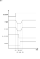
- Figure 4 is a timing chart showing an example of the switching timing of windings 21u, 22u, 21v, 22v, 21w, and 22w of motor 20 in the winding switching system according to the first embodiment.
- Figure 4 shows an example of the timing of a speed change command, the current supplied to motor 20 (hereinafter also referred to as "motor current"), the output torque of motor 20 (hereinafter also referred to as "motor torque"), and the on/off switching of semiconductor relays 111u, 112u, 113u, 111v, 112v, 113v, 111w, 112w, and 113w when the connection state of windings 21u, 22u, 21v, 22v, 21w, and 22w of motor 20 is switched from a series connection state to a parallel connection state.
- motor current the current supplied to motor 20
- motor torque the output torque of motor 20
- the semiconductor relays 111u, 111v, and 111w are collectively referred to as “relays 111," the semiconductor relays 112u, 112v, and 112w are collectively referred to as “relays 112,” and the semiconductor relays 113u, 113v, and 113w are collectively referred to as “relays 113.”
- a gear change command (electrical downshift command) is input to the control device 50.
- the torque control unit 511 reduces the motor current Iq from time t11.
- the motor current Iq is the effective current (Q-axis current) of the AC current provided to the motor 20.
- the motor current Iq gradually decreases in a ramp shape. As the motor current Iq decreases, the motor torque also decreases.
- the motor current Iq reaches the first target value Th1.
- the torque control unit 511 stops the reduction of the motor current Iq from time t12 when the motor current Iq reaches the first target value Th1. In other words, from time t12 onwards, the motor current Iq is maintained at the first target value Th1. From time t12 onwards, the reduction of the motor torque also stops.
- the switching control unit 512 switches the connection state of the windings 21u, 22u, 21v, 22v, 21w, and 22w from a series connection state to a parallel connection state at a timing after time t12.
- the relays 111 and 113 are switched from an on state to an off state
- time t02 which is after time t01
- the relay 112 is switched from an off state to an on state.
- all of the relays 111, 112, and 113 are in the off state. This prevents all of the relays 111, 112, and 113 from being in the on state when switching the connection state of the windings 21u, 22u, 21v, 22v, 21w, and 22w.
- the torque control unit 511 increases the motor current Iq.
- the target value of the motor current Iq at this time is determined based on the target torque in the parallel connection state of the windings 21u, 22u, 21v, 22v, 21w, and 22w.
- the target torque is determined based on the rotation speed of the motor 20, the output torque of the motor 20, the depression amount of the brake pedal 70 (braking command amount), and the depression amount of the accelerator pedal 80 (acceleration command amount).
- the motor current Iq increases in a ramp shape. As the motor current Iq increases, the motor torque also increases.
- the motor current Iq reaches the target value. From time t22 when the motor current Iq reaches the target value, the torque control unit 511 stops increasing the motor current Iq. After time t22, the increase in the motor torque also stops.
- connection state of the windings 21u, 22u, 21v, 22v, 21w, and 22w of the motor 20 is switched from a series connection state to a parallel connection state, so the performance of the motor 20 can be efficiently utilized to electrically change speed from a low rotation, high torque state to a high rotation, low torque state. Furthermore, as the connection state of the windings 21u, 22u, 21v, 22v, 21w, and 22w of the motor 20 is switched, the output torque of the motor 20 decreases, so the driver can be given the same feeling of shifting as with a mechanical transmission.
- First target value Th1 is, for example, 0 A. If the connection state is switched while current is flowing through windings 21u, 22u, 21v, 22v, 21w, and 22w, a torque shock occurs due to a sudden change in current through windings 21u, 22u, 21v, 22v, 21w, and 22w, which are inductive loads. Furthermore, damage to relays 111, 112, and 113 due to a surge also occurs. By setting first target value Th1 to 0 A, the above-mentioned torque shock and damage to relays 111, 112, and 113 due to a surge can be suppressed.
- the torque control unit 511 reduces the output torque of the motor 20 by reducing the AC current output from the power converter 30 at the second shift timing.
- the switching control unit 512 causes the winding switching device 100 to switch the connection state of the windings 21u, 22u, 21v, 22v, 21w, and 22w of the motor 20 from a parallel connection state to a series connection state.
- the second shift timing is the timing when an electrical downshift is instructed.
- connection state of the windings 21u, 22u, 21v, 22v, 21w, and 22w of the motor 20 is switched from a parallel connection state to a series connection state, so that the performance of the motor 20 can be efficiently utilized to electrically change the speed from a high rotation, low torque state to a low rotation, high torque state. Furthermore, as the connection state of the windings 21u, 22u, 21v, 22v, 21w, and 22w of the motor 20 is switched, the output torque of the motor 20 increases, so that the driver can be given a shifting sensation similar to that of a mechanical transmission.
- the torque control unit 511 increases the output torque of the motor 20 by increasing the AC current output from the power converter 30 at the second shift timing.
- a torque for braking the vehicle i.e., a negative torque
- the switching control unit 512 causes the winding switching device 100 to switch the connection state of the windings 21u, 22u, 21v, 22v, 21w, and 22w of the motor 20 from a parallel connection state to a series connection state.
- connection state of the windings 21u, 22u, 21v, 22v, 21w, and 22w of the motor 20 is switched from a parallel connection state to a series connection state, the performance of the motor 20 can be efficiently utilized to electrically shift from a high rotation, low torque state to a low rotation, high torque state.
- the amount of regeneration by the motor 20 is higher in a low rotation, high torque state than in a high rotation, low torque state. Therefore, the regenerative braking force can be increased by electrical downshifting, and the driver can be given a deceleration sensation similar to that of engine braking.
- the driver can be given a shifting sensation similar to that of a mechanical transmission.
- the torque control unit 511 can gradually increase the motor current Iq in a ramp-like manner during an electrical downshift.
- the motor current Iq gradually decreases in a ramp-like manner during an electrical upshift, and the motor current Iq gradually increases in a ramp-like manner during an electrical downshift, providing the driver with a natural feeling of gear shifting.
- the second target value Th2 is, for example, 0 A. This makes it possible to suppress damage to relays 111, 112, and 113 due to torque shocks and surges caused by sudden changes in current in windings 21u, 22u, 21v, 22v, 21w, and 22w.
- the torque control unit 511 increases the output torque of the motor 20 by increasing the AC current output from the power converter 30 at the first shift timing.
- the switching control unit 512 causes the winding switching device 100 to switch the connection state of the windings 21u, 22u, 21v, 22v, 21w, and 22w of the motor 20 from a series connection state to a parallel connection state.
- connection state of the windings 21u, 22u, 21v, 22v, 21w, and 22w of the motor 20 is switched from a series connection state to a parallel connection state, so that the performance of the motor 20 can be efficiently utilized to electrically shift from a low rotation, high torque state to a high rotation, low torque state.
- electrically shifting up the regenerative braking force can be reduced, and the driver can be given a deceleration sensation similar to that of engine braking.
- connection state of the windings 21u, 22u, 21v, 22v, 21w, and 22w of the motor 20 is switched, the negative output torque of the motor 20 increases (the absolute value of the output torque decreases), so that the driver can be given a shifting sensation similar to that of a mechanical transmission.
- the processor 501 executes the motor control program 510 to perform electrical up-shifting processing and electrical down-shifting processing.
- FIG. 5 is a flowchart showing an example of an electrical upshift process performed by the control device according to the first embodiment.
- windings 21u, 22u, 21v, 22v, 21w, and 22w of motor 20 are connected in series at the start of the electrical upshift process.
- the processor 501 receives the instruction to electrically upshift (step S101).
- the processor 501 refers to the detection signal of the torque sensor 202 and determines whether the motor torque is positive, i.e., whether the motor 20 is generating torque for accelerating the vehicle or maintaining its speed (hereinafter referred to as "acceleration torque") (step S102).
- step S102 If the motor torque is positive (YES in step S102), the processor 501 outputs an instruction to the power converter 30 to reduce the motor current Iq (step S103). This starts the reduction of the motor current Iq.
- the processor 501 obtains the current value of the motor current Iq from the detection signals of the current sensors 33u, 33v, and 33w, and determines whether the motor current Iq is equal to or less than the first target value Th1 (step S104).
- step S104 If the motor current Iq is greater than the first target value Th1 (NO in step S104), the processor 501 executes step S104 again. If the motor current Iq is equal to or less than the first target value Th1 (YES in step S104), the processor 501 outputs an instruction to the power converter 30 to stop the reduction of the motor current Iq (step S105). This stops the reduction of the motor current Iq.
- the processor 501 outputs an instruction to the winding switching device 100 to switch the connection state of the windings 21u, 22u, 21v, 22v, 21w, and 22w of the motor 20 from a series connection state to a parallel connection state (step S106).
- the motor current Iq is equal to or less than the first target value Th1
- the connection state of the windings 21u, 22u, 21v, 22v, 21w, and 22w is switched from a series connection state to a parallel connection state, and an electrical upshift is performed.
- the processor 501 After outputting an instruction to switch the connection state of the windings 21u, 22u, 21v, 22v, 21w, and 22w of the motor 20, the processor 501 outputs an instruction to increase the motor current Iq to the power converter 30 (step S107). This starts the increase in the motor current Iq.
- the processor 501 When the motor current reaches the target value determined based on the target torque in the parallel connection state of the windings 21u, 22u, 21v, 22v, 21w, and 22w, the processor 501 outputs an instruction to the power converter 30 to stop the increase in the motor current Iq (step S108). This stops the increase in the motor current Iq. This completes the electrical shift-up process when the motor torque is positive.
- the motor 20 is performing regenerative braking.
- the power converter 30 functions as a DC/AC converter and converts the AC current output from the motor 20 into a DC current.
- the converted DC current is output to the battery 40 and stored.
- the processor 501 outputs an instruction to the power converter 30 to increase the motor current Iq (step S109). This starts the increase in the motor current Iq.
- the processor 501 obtains the current value of the motor current Iq from the detection signals of the current sensors 33u, 33v, and 33w, and determines whether the motor current Iq is greater than or equal to the second target value Th2 (step S110).
- step S110 If the motor current Iq is smaller than the second target value Th2 (NO in step S110), the processor 501 executes step S110 again. If the motor current Iq is equal to or greater than the second target value Th2 (YES in step S110), the processor 501 outputs an instruction to the power converter 30 to stop the increase in the motor current Iq (step S111). This stops the increase in the motor current Iq.
- the processor 501 outputs an instruction to the winding switching device 100 to switch the connection state of the windings 21u, 22u, 21v, 22v, 21w, and 22w of the motor 20 from a series connection state to a parallel connection state (step S112).
- the motor current Iq is equal to or greater than the second target value Th2
- the connection state of the windings 21u, 22u, 21v, 22v, 21w, and 22w is switched from a series connection state to a parallel connection state, and an electrical upshift is performed.
- the processor 501 After outputting an instruction to switch the connection state of the windings 21u, 22u, 21v, 22v, 21w, and 22w of the motor 20, the processor 501 outputs an instruction to reduce the motor current Iq to the power converter 30 (step S112). This starts the reduction of the motor current Iq.
- the processor 501 When the motor current reaches the target value determined based on the target torque in the parallel connection state of the windings 21u, 22u, 21v, 22v, 21w, and 22w, the processor 501 outputs an instruction to the power converter 30 to stop the reduction in the motor current Iq (step S113). This stops the reduction in the motor current Iq. This completes the electrical shift-up process when the motor torque is negative.
- FIG. 6 is a flowchart showing an example of an electrical downshifting process performed by the control device according to the first embodiment. In this example, it is assumed that windings 21u, 22u, 21v, 22v, 21w, and 22w of motor 20 are connected in parallel at the start of the electrical downshifting process.
- the processor 501 accepts the instruction to electrically downshift (step S201).
- the processor 501 refers to the detection signal of the torque sensor 202 and determines whether the motor torque is positive, i.e., whether the motor 20 is generating an acceleration torque (step S202).
- step S202 If the motor torque is positive (YES in step S202), the processor 501 outputs an instruction to the power converter 30 to reduce the motor current Iq (step S203). This starts the reduction of the motor current Iq.
- the processor 501 obtains the current value of the motor current Iq from the detection signals of the current sensors 33u, 33v, and 33w, and determines whether the motor current Iq is equal to or less than the first target value Th1 (step S204).
- step S204 If the motor current Iq is greater than the first target value Th1 (NO in step S204), the processor 501 executes step S204 again. If the motor current Iq is equal to or less than the first target value Th1 (YES in step S204), the processor 501 outputs an instruction to the power converter 30 to stop the reduction of the motor current Iq (step S205). This stops the reduction of the motor current Iq.
- the processor 501 outputs an instruction to the winding switching device 100 to switch the connection state of the windings 21u, 22u, 21v, 22v, 21w, and 22w of the motor 20 from a parallel connection state to a series connection state (step S206).
- the motor current Iq is equal to or less than the first target value Th1
- the connection state of the windings 21u, 22u, 21v, 22v, 21w, and 22w is switched from a parallel connection state to a series connection state, and an electrical downshift is performed.
- the processor 501 After outputting an instruction to switch the connection state of the windings 21u, 22u, 21v, 22v, 21w, and 22w of the motor 20, the processor 501 outputs an instruction to increase the motor current Iq to the power converter 30 (step S207). This starts the increase in the motor current Iq.
- the processor 501 When the motor current reaches the target value determined based on the target torque in the parallel connection state of the windings 21u, 22u, 21v, 22v, 21w, and 22w, the processor 501 outputs an instruction to the power converter 30 to stop the increase in the motor current Iq (step S208). This stops the increase in the motor current Iq. This completes the electrical downshift process when the motor torque is positive.
- step S202 If the motor torque is negative (NO in step S202), the motor 20 is performing regenerative braking.
- the processor 501 outputs an instruction to the power converter 30 to increase the motor current Iq (step S209). This starts the increase in the motor current Iq.
- the processor 501 obtains the current value of the motor current Iq from the detection signals of the current sensors 33u, 33v, and 33w, and determines whether the motor current Iq is greater than or equal to the second target value Th2 (step S210).
- step S210 If the motor current Iq is smaller than the second target value Th2 (NO in step S210), the processor 501 executes step S210 again. If the motor current Iq is equal to or greater than the second target value Th2 (YES in step S210), the processor 501 outputs an instruction to the power converter 30 to stop the increase in the motor current Iq (step S211). This stops the increase in the motor current Iq.
- the processor 501 outputs an instruction to the winding switching device 100 to switch the connection state of the windings 21u, 22u, 21v, 22v, 21w, and 22w of the motor 20 from a parallel connection state to a series connection state (step S212).
- the motor current Iq is equal to or greater than the second target value Th2
- the connection state of the windings 21u, 22u, 21v, 22v, 21w, and 22w is switched from a parallel connection state to a series connection state, and an electrical downshift is performed.
- the processor 501 After outputting an instruction to switch the connection state of the windings 21u, 22u, 21v, 22v, 21w, and 22w of the motor 20, the processor 501 outputs an instruction to reduce the motor current Iq to the power converter 30 (step S212). This starts the reduction of the motor current Iq.
- the processor 501 When the motor current reaches the target value determined based on the target torque in the parallel connection state of the windings 21u, 22u, 21v, 22v, 21w, and 22w, the processor 501 outputs an instruction to the power converter 30 to stop the reduction of the motor current Iq (step S213). This stops the reduction of the motor current Iq. This completes the electrical downshift process when the motor torque is negative.
- the winding switching device of the second embodiment switches the connection state of the multiple windings of a motor between a full connection state in which all of the multiple windings are connected, and a partial connection state in which some of the multiple windings are connected.
- FIG. 7 is a circuit diagram showing an example of the configuration of a winding switching device according to the second embodiment.
- Motor 20A includes a plurality of windings 24u, 25u, 24v, 25v, 24w, and 25w. Windings 24u and 25u correspond to the U phase, windings 24v and 25v correspond to the V phase, and windings 24w and 25w correspond to the W phase. However, the number of windings for each phase is not limited to two, and may be three or more.
- the winding switching device 100A switches the connection state of the windings 24u, 25u, 24v, 25v, 24w, and 25w for each phase between a fully connected state and a partially connected state.
- the winding switching device 100A includes control circuits 103u, 103v, and 103w and switching circuits 140u, 140v, and 140w.
- the switching circuits 140u, 140v, and 140w switch the connection state of the windings 24u, 25u, 24v, 25v, 24w, and 25w between a fully connected state and a partially connected state.
- the fully connected state is an example of a first connection state
- the partially connected state is an example of a second connection state.
- Power line 35u is connected to one end of winding 24u.
- the other end of winding 24u and one end of winding 25u are connected to each other, and power line 241u extends from the midpoint between winding 24u and winding 25u.
- Power line 241u branches into power lines 242u and 243w.
- Power line 251u extends from the other end of winding 25u.
- Power line 251u branches into power lines 252u and 253w.
- Power line 35v is connected to one end of winding 24v.
- the other end of winding 24v and one end of winding 25v are connected to each other, and power line 241v extends from the midpoint between winding 24v and winding 25v.
- Power line 241v branches into power lines 242v and 243u.
- Power line 251v extends from the other end of winding 25v.
- Power line 251v branches into power lines 252v and 253u.
- Power line 35w is connected to one end of winding 24w.
- the other end of winding 24w and one end of winding 25w are connected to each other, and power line 241w extends from the midpoint between winding 24w and winding 25w.
- Power line 241w branches into power lines 242w and 243v.
- Power line 251w extends from the other end of winding 25w.
- Power line 251w branches into power lines 252w and 253v.
- the switching circuit 140u includes semiconductor relays 141u and 142u.
- the switching circuit 140v includes semiconductor relays 141v and 142v.
- the switching circuit 140w includes semiconductor relays 141w and 142w.
- the semiconductor relays 141u, 142u, 141v, 142v, 141w, and 142w are, for example, IGBTs or power MOSFETs.
- the first terminal of the semiconductor relay 141u is connected to the power line 242u, and the second terminal is connected to the power line 243u.
- the first terminal of the semiconductor relay 142u is connected to the power line 252u, and the second terminal is connected to the power line 253u.
- the connection relationship between the switching circuits 140v and 140w is the same as that of the switching circuit 140u, so a description is omitted.
- winding switching device 100A according to the second embodiment are similar to those of the winding switching device 100 according to the first embodiment, so the same components are given the same reference numerals and their description is omitted.
- an electrical upshift is performed by switching the connection state of the windings 24u, 25u, 24v, 25v, 24w, and 25w of the motor 20 from a full connection state to a partial connection state.
- An electrical downshift is performed by switching the connection state of the windings 24u, 25u, 24v, 25v, 24w, and 25w of the motor 20 from a partial connection state to a full connection state.
- the torque control unit 511 changes the effective current of the AC current output from the power converter 30 in a stepwise manner based on the shift timing.
- FIG. 8 is a timing chart showing an example of the switching timing of windings 21u, 22u, 21v, 22v, 21w, and 22w of motor 20 in the winding switching system according to the third embodiment.
- the configuration of the winding switching system according to the third embodiment is the same as the configuration of winding switching system 10 according to the first embodiment, so the same components are given the same reference numerals and descriptions thereof are omitted.
- FIG. 8 shows an example of the timing of the gear shift command, motor current, motor torque, and on/off switching of semiconductor relays 111, 112, and 113 when the connection state of windings 21u, 22u, 21v, 22v, 21w, and 22w of motor 20 is switched from a series connection state to a parallel connection state.
- a gear change command (electrical upshift command) is input to the control device 50.
- the torque control unit 511 reduces the motor current Iq in a stepwise manner to a value equal to or less than the first target value Th1. As the motor current Iq decreases, the motor torque also decreases in a stepwise manner. After time t1, the motor current Iq is maintained at the first target value Th1.
- the switching control unit 512 switches the connection state of the windings 21u, 22u, 21v, 22v, 21w, and 22w from a series connection state to a parallel connection state at a timing after time t1.
- the relays 111 and 113 are switched from an on state to an off state
- time t02 which is after time t01
- the relay 112 is switched from an off state to an on state.
- all of the relays 111, 112, and 113 are in the off state. This prevents all of the relays 111, 112, and 113 from being in the on state when switching the connection state of the windings 21u, 22u, 21v, 22v, 21w, and 22w.
- the torque control unit 511 increases the motor current Iq in a stepwise manner.
- the target value of the motor current Iq at this time is determined based on the target torque in the parallel connection state of the windings 21u, 22u, 21v, 22v, 21w, and 22w.
- the target torque is determined based on the rotation speed of the motor 20, the output torque of the motor 20, the depression amount of the brake pedal 70 (braking command amount), and the depression amount of the accelerator pedal 80 (acceleration command amount).
- the motor current Iq increases, the motor torque also increases in a stepwise manner.
- the output torque of the motor 20 decreases in a step-like manner, giving the driver the same feeling of shifting as with a mechanical transmission.
- the torque control unit 511 changes the effective current of the AC current output from the power converter 30 in a curved manner based on the shift timing.
- Fig. 9 is a timing chart showing an example of the switching timing of windings 21u, 22u, 21v, 22v, 21w, and 22w of motor 20 in the winding switching system according to the fourth embodiment.
- Fig. 9 shows an example of the timing of the speed change command, motor current, motor torque, and on/off switching of semiconductor relays 111, 112, and 113 when the connection state of windings 21u, 22u, 21v, 22v, 21w, and 22w of motor 20 is switched from a series connection state to a parallel connection state.
- a gear change command (electrical upshift command) is input to the control device 50.
- the torque control unit 511 reduces the motor current Iq in a curved manner from time t11.
- the slope of the decrease in the motor current Iq gradually increases from time t11, and the slope becomes infinite at the midpoint between time t11 and time t12. Thereafter, the slope of the decrease in the motor current Iq gradually decreases, and at time t12 the slope becomes 0 (stops decreasing).
- the motor current Iq reaches the first target value Th1.
- the torque control unit 511 stops the reduction of the motor current Iq from time t12 when the motor current Iq reaches the first target value Th1. In other words, from time t12 onwards, the motor current Iq is maintained at the first target value Th1. From time t12 onwards, the reduction of the motor torque also stops.
- the switching control unit 512 switches the connection state of the windings 21u, 22u, 21v, 22v, 21w, and 22w from a series connection state to a parallel connection state at a timing after time t12.
- the relays 111 and 113 are switched from an on state to an off state
- time t02 which is after time t01
- the relay 112 is switched from an off state to an on state.
- all of the relays 111, 112, and 113 are in the off state. This prevents all of the relays 111, 112, and 113 from being in the on state when switching the connection state of the windings 21u, 22u, 21v, 22v, 21w, and 22w.
- the torque control unit 511 increases the motor current Iq.
- the target value of the motor current Iq at this time is determined based on the target torque in the parallel connection state of the windings 21u, 22u, 21v, 22v, 21w, and 22w.
- the target torque is determined based on the rotation speed of the motor 20, the output torque of the motor 20, the depression amount of the brake pedal 70 (braking command amount), and the depression amount of the accelerator pedal 80 (acceleration command amount).
- the motor current Iq increases in a curved line. As the motor current Iq increases, the motor torque also increases.
- the slope of the increase in motor current Iq gradually increases from time t21, and the slope becomes infinite at the midpoint between time t21 and time t22. After that, the slope of the increase in motor current Iq gradually decreases, and at time t22 the slope becomes 0 (stops increasing).
- the motor current Iq reaches the target value. From time t22 when the motor current Iq reaches the target value, the torque control unit 511 stops increasing the motor current Iq. After time t22, the increase in the motor torque also stops.
- the output torque of the motor 20 decreases in a curved manner.
- sharp changes in the motor torque are suppressed, so that the driver can be given a shifting sensation similar to that of a mechanical transmission.
- the torque control unit 511 executes a pseudo-shift control process to reduce and then increase the AC current output from the power converter 30 at a pseudo-shift timing different from the timing of the electrical up-shift and electrical down-shift (electrical shift timing).
- FIG. 10 is a timing chart showing an example of pseudo-speed change control processing in the winding switching system according to the fifth embodiment.
- FIG. 10 shows an example of the timing of a speed change command, motor current, motor torque, and on/off switching of semiconductor relays 111, 112, and 113 when the connection state of windings 21u, 22u, 21v, 22v, 21w, and 22w of motor 20 is switched from a series connection state to a parallel connection state.
- a gear shift command (pseudo gear shift command) is input to the control device 50.
- the torque control unit 511 reduces the motor current Iq from time t31.
- the motor current Iq gradually decreases in a ramp shape. As the motor current Iq decreases, the motor torque also decreases.
- the motor current Iq reaches the third target value Th1.
- the torque control unit 511 stops the reduction of the motor current Iq from time t32 when the motor current Iq reaches the first target value Th1. In other words, from time t32 onwards, the motor current Iq is maintained at the first target value Th1. From time t32 onwards, the reduction of the motor torque also stops.
- the torque control unit 511 maintains the motor current Iq at the first target value Th1 for a certain period of time. During this period, the switching control unit 512 does not switch the connection state of the windings 21u, 22u, 21v, 22v, 21w, and 22w. In other words, the semiconductor relays 111 and 113 maintain the ON state, and the semiconductor relay 112 maintains the OFF state.
- the torque control unit 511 increases the motor current Iq. That is, the torque control unit 511 increases the motor current Iq after maintaining it at the first target value Th1 for a certain period of time. Note that the torque control unit 511 may increase the motor current Iq without providing a stop period after the motor current Iq has decreased to the first target value Th1 or less.
- the target value of the motor current Iq at this time is the same as the target value before the change in the motor current Iq.
- the motor current Iq increases in a ramp shape. As the motor current Iq increases, the motor torque also increases.
- the motor current Iq reaches the target value. From time t42 when the motor current Iq reaches the target value, the torque control unit 511 stops increasing the motor current Iq. After time t42, the increase in the motor torque also stops.
- FIG. 11 is a flowchart showing an example of pseudo-shift processing by the control device according to the fifth embodiment.
- the driver operates the gear shift indicator 90 to input a gear shift instruction to the vehicle.
- the processor 501 accepts the gear shift instruction (step S301).
- the processor 501 refers to the detection signal of the torque sensor 202 and determines whether the motor torque is positive, i.e., whether the motor 20 is generating an acceleration torque (step S302).
- step S302 If the motor torque is positive (YES in step S302), the processor 501 outputs an instruction to the power converter 30 to reduce the motor current Iq (step S303). This starts the reduction of the motor current Iq.
- the processor 501 obtains the current value of the motor current Iq from the detection signals of the current sensors 33u, 33v, and 33w, and determines whether the motor current Iq is equal to or less than the first target value Th1 (step S304).
- step S304 If the motor current Iq is greater than the first target value Th1 (NO in step S304), the processor 501 executes step S304 again. If the motor current Iq is equal to or less than the first target value Th1 (YES in step S304), the processor 501 outputs an instruction to the power converter 30 to stop the reduction of the motor current Iq (step S305). This stops the reduction of the motor current Iq.
- the processor 501 outputs an instruction to increase the motor current Iq to the power converter 30 without switching the connection state of the windings 21u, 22u, 21v, 22v, 21w, and 22w of the motor 20 (step S306). This starts the increase in the motor current Iq.
- the processor 501 When the motor current Iq reaches the same target value as the target value before the change in the motor current Iq, the processor 501 outputs an instruction to the power converter 30 to stop the increase in the motor current Iq (step S307). This stops the increase in the motor current Iq. This completes the pseudo-speed change process when the motor torque is positive.
- step S302 If the motor torque is negative (NO in step S302), the motor 20 is performing regenerative braking. In this case, the processor 501 outputs an instruction to the power converter 30 to increase the motor current Iq (step S308). This starts the increase in the motor current Iq.
- the processor 501 obtains the current value of the motor current Iq from the detection signals of the current sensors 33u, 33v, and 33w, and determines whether the motor current Iq is greater than or equal to the second target value Th2 (step S309).
- step S309 If the motor current Iq is smaller than the second target value Th2 (NO in step S309), the processor 501 executes step S309 again. If the motor current Iq is equal to or greater than the second target value Th2 (YES in step S309), the processor 501 outputs an instruction to the power converter 30 to stop the increase in the motor current Iq (step S310). This stops the increase in the motor current Iq.
- the processor 501 outputs an instruction to the power converter 30 to reduce the motor current Iq without switching the connection state of the windings 21u, 22u, 21v, 22v, 21w, and 22w of the motor 20 (step S311). This starts the reduction of the motor current Iq.
- the processor 501 When the motor current Iq reaches the same target value as the target value before the change in the motor current Iq, the processor 501 outputs an instruction to the power converter 30 to stop the reduction in the motor current Iq (step S312). This stops the reduction in the motor current Iq. This completes the pseudo-speed change process when the motor torque is negative.
- the output torque of the motor 20 changes in response to a gear shift command without switching the connection state of the windings 21u, 22u, 21v, 22v, 21w, and 22w of the motor 20, so the driver can feel a pseudo gear shift even when no electrical gear shift is performed.
- the driver can be made to feel a simulated sensation of multi-speed shifting.
- pseudo-shifting process when switching between 1st and 2nd gear, between 2nd and 3rd gear, between 4th and 5th gear, and between 5th and 6th gear
- electrical shifting process electrical up-shifting process and electrical down-shifting process
- the driver can be made to feel a simulated sensation of six-speed shifting, while electrical shifting that efficiently utilizes the performance of the motor can be performed when switching between 3rd and 4th gear.
- the winding switching device 100 has voltage sensors 34u, 34v, and 34w that detect the voltages in the windings 21u, 21v, and 21w.
- a voltage sensor 34u is arranged between the power lines 35u and 212u
- a voltage sensor 34v is arranged between the power lines 35v and 212v
- a voltage sensor 34w is arranged between the power lines 35w and 212w.
- the voltage sensors 34u, 34v, and 34w are connected to the control device 50.
- the control device 50 can receive the detection values of the voltage sensors 34u, 34v, and 34w.
- winding switching system 10 The other configurations of the winding switching system according to the sixth embodiment are similar to those of the winding switching system 10 according to the first embodiment, so the same components are given the same reference numerals and their description is omitted.
- FIG. 12 is a functional block diagram showing an example of the functions of the control device according to the sixth embodiment.
- the control device 50A includes the functions of a first determination unit 513, a judgment unit 514, a prohibition unit 515, and a second determination unit 516.
- the functions of the torque control unit 511 and the switching control unit 512 are the same as those in the first embodiment, so detailed explanations will be omitted.
- the first determination unit 513 determines the timing before the induced voltage generated in the windings 21u, 22u, 21v, 22v, 21w, 22w exceeds the output voltage of the battery 40 as the first forced shift timing when the connection state of the multiple windings 21u, 22u, 21v, 22v, 21w, 22w is a series connection state.
- the first forced shift timing is the timing for starting the forced switching of the connection state of the windings 21u, 22u, 21v, 22v, 21w, 22w from the series connection state to the parallel connection state, regardless of the presence or absence of a shift command from the shift indicator 90 or the automatic shift control device.
- An induced voltage is generated in the windings 21u, 22u, 21v, 22v, 21w, and 22w according to the rotation speed of the motor 20.
- the power converter 30 can control the applied voltage of the windings 21u, 22u, 21v, 22v, 21w, and 22w within the range of the output voltage of the battery 40. Since the polarity of the induced voltage in the windings 21u, 22u, 21v, 22v, 21w, and 22w is opposite to the polarity of the applied voltage, if the induced voltage exceeds the output voltage of the battery 40, the current in the windings 21, 22u, 21v, 22v, 21w, and 22w cannot be reduced to zero. Therefore, if the first target value Th1 is 0A and the induced voltage exceeds the output voltage of the battery 40, the motor current Iq cannot be reduced to the first target value Th1 in the electrical shift-up process.
- the first determination unit 513 monitors the induced voltages generated in the windings 21u, 22u, 21v, 22v, 21w, and 22w in the series connection state, and determines the timing before the induced voltage transitions from a range below the output voltage of the battery 40 to a range above the output voltage as the first forced shift timing.
- the torque control unit 511 changes the output torque of the motor 20 by changing the AC current output from the power converter 30 at the first forced shift timing determined by the first determination unit 513. After the AC current has changed, the switching control unit 512 causes the winding switching device 100 to switch the connection state of the windings 21u, 22u, 21v, 22v, 21w, and 22w from a series connection state to a parallel connection state.
- the first determination unit 513 determines the first forced shift timing, it generates an electrical upshift command. This starts the electrical upshift process.
- the first determination unit 513 can determine the timing at which the physical quantity related to the induced voltage exceeds a first threshold value corresponding to the output voltage of the battery 40 as the first forced gear shift timing.
- the physical quantity is, for example, the rotation speed of the motor 20.
- the first determination unit 513 can obtain a detection value from the rotation sensor 201.
- Another example of the physical quantity is the voltage in the windings 21u, 21v, and 21w.
- the detection value can be obtained from each of the voltage sensors 34u, 34v, and 34w.
- the physical quantity may be the current flowing through the windings 21u, 22u, 21v, 22v, 21w, and 22w, or the output torque of the motor 20.
- the physical quantity is the rotation speed of the motor 20.
- the determination unit 514 determines whether or not the induced voltage exceeds the output voltage of the battery after the connection state of the windings 21u, 22u, 21v, 22v, 21w, and 22w is switched from a parallel connection state to a series connection state.
- the determination unit 514 can determine whether the physical quantity related to the induced voltage in the series connection state is equal to or less than the second threshold value corresponding to the output voltage of the battery 40. More specifically, the determination unit 514 acquires the rotation speed of the motor 20. From the rotation speed of the motor 20, the induced voltage when the windings 21u, 22u, 21v, 22v, 21w, and 22w are in a series connection state can be identified.
- the second threshold value is, for example, the rotation speed of the motor 20 when the induced voltage when the windings 21u, 22u, 21v, 22v, 21w, and 22w are in a series connection state becomes equal to the output voltage of the battery 40.
- the second threshold value is not limited to this.
- the second threshold value may be the rotation speed of the motor 20 when the induced voltage when the windings 21u, 22u, 21v, 22v, 21w, and 22w are in a series connection state is lower than the output voltage of the battery 40 by a predetermined margin.
- the prohibition unit 515 prohibits the switching control unit 512 from switching the connection state of the windings 21u, 22u, 21v, 22v, 21w, and 22w.
- the prohibition unit 515 prohibits the switching control unit 512 from switching the connection state of the windings 21u, 22u, 21v, 22v, 21w, and 22w while the rotation speed of the motor 20 exceeds the second threshold value. This switches the connection state of the windings 21u, 22u, 21v, 22v, 21w, and 22w from a parallel connection state to a series connection state, preventing the induced voltage from exceeding the output voltage of the battery 40.
- the prohibition unit 515 cancels the prohibition of the switching control unit 512 from switching the connection state of the windings 21u, 22u, 21v, 22v, 21w, and 22w.
- the second determination unit 516 determines the timing after the induced voltage becomes equal to or lower than the output voltage of the battery 40 after the connection state of the windings 21u, 22u, 21v, 22v, 21w, 22w is switched from the parallel connection state to the series connection state when the connection state of the multiple windings 21u, 22u, 21v, 22v, 21w, 22w is in the parallel connection state as the second forced shift timing.
- the second forced shift timing is the timing for starting the forced switching of the connection state of the windings 21u, 22u, 21v, 22v, 21w, 22w from the parallel connection state to the series connection state, regardless of the presence or absence of a shift command from the shift indicator 90 or the automatic shift control device.
- the second determination unit 516 estimates the induced voltage generated in the windings 21u, 22u, 21v, 22v, 21w, and 22w in the series connection state, and determines the timing at which the induced voltage transitions from a range exceeding the output voltage of the battery 40 to a range below the output voltage of the battery 40 as the second forced shift timing.
- the torque control unit 511 changes the output torque of the motor 20 by changing the AC current output from the power converter 30 at the second forced shift timing determined by the second determination unit 516. After the AC current has changed, the switching control unit 512 causes the winding switching device 100 to switch the connection state of the windings 21u, 22u, 21v, 22v, 21w, and 22w from a parallel connection state to a series connection state.
- the second determination unit 516 when the second determination unit 516 determines the second forced shift timing, it generates an electrical downshift command. This starts the electrical downshift process.
- the second determination unit 516 can determine, as the second forced shift timing, the timing at which the physical quantity related to the induced voltage becomes equal to or less than a second threshold value corresponding to the output voltage of the battery 40. For example, the second determination unit 516 determines, as the second forced shift timing, the timing at which the rotation speed of the motor 20 becomes equal to or less than the second threshold value.
- the control device 50A executes the following forced shift-up determination process and forced shift-down determination process.
- FIG. 13 is a flowchart showing an example of a forced upshift determination process performed by the control device according to the sixth embodiment. In this example, it is assumed that windings 21u, 22u, 21v, 22v, 21w, and 22w of motor 20 are connected in series.
- the rotation sensor 201 detects the rotation speed of the output shaft of the motor 20 and outputs the detected rotation speed. For example, the rotation sensor 201 detects the rotation speed at a constant cycle and outputs the detection result.
- the control device 50A receives the detection value of the rotation speed output from the rotation sensor 201 (step S401).
- the processor 501 compares the acquired rotation speed R with the first threshold value Th1_R and determines whether the rotation speed R exceeds the first threshold value Th1_R (step S402).
- the first threshold value Th1_R is a value that is a predetermined margin lower than the rotation speed of the motor 20 when the induced voltage generated in the windings 21u, 22u, 21v, 22v, 21w, and 22w in the series connection state matches the output voltage of the battery 40.
- step S402 If the rotation speed R is equal to or less than the first threshold value Th1_R (NO in step S402), the processor 501 returns to step S401.
- step S402 If the rotation speed R exceeds the first threshold value Th1_R (YES in step S402), the processor 501 determines that timing as the first forced shift timing. The processor 501 generates an electrical upshift command (step S403).
- step S404 the processor 501 starts the electrical upshift process (step S404).
- the connection state of the windings 21u, 22u, 21v, 22v, 21w, and 22w switches from a series connection state to a parallel connection state. This completes the forced upshift determination process.
- FIG. 14 is a flowchart showing an example of a forced downshift determination process performed by the control device according to the sixth embodiment. In this example, it is assumed that windings 21u, 22u, 21v, 22v, 21w, and 22w of motor 20 are connected in parallel.
- the control device 50A receives the detected value of the rotation speed output from the rotation sensor 201 (step S501).
- the processor 501 compares the acquired rotation speed R with the second threshold value Th2_R and determines whether the rotation speed R is equal to or lower than the second threshold value Th2_R (step S502).
- the second threshold value Th2_R is a value lower than the rotation speed of the motor 20 by a predetermined margin when the induced voltage generated in the windings 21u, 22u, 21v, 22v, 21w, and 22w in the series connection state matches the output voltage of the battery 40.
- the second threshold value Th2_R may be the same value as the first threshold value Th1_R, or may be a different value.
- the second threshold value Th2_R is a value lower than the first threshold value Th1_R. This makes it possible to prevent the rotation speed R from exceeding the first threshold value Th1_R soon after the electrical downshift is completed, causing a forced upshift.
- step S503 If the rotation speed R is greater than the second threshold value Th2_R (NO in step S502), the processor 501 prohibits an electrical downshift (step S503). As a result, even if an electrical downshift command is given by the driver, for example, an electrical downshift is not executed. With electrical downshifts prohibited, the processor 501 returns to step S501.
- step S502 determines that timing as the second forced shift timing. In this case, if electrical downshifting is prohibited, the processor 501 releases the prohibition of electrical downshifting. Once the processor 501 determines the second forced shift timing, it generates an electrical downshift instruction (step S504).
- step S505 the processor 501 starts the electrical downshift process (step S505).
- the connection state of the windings 21u, 22u, 21v, 22v, 21w, and 22w switches from a parallel connection state to a series connection state. This completes the forced downshift determination process.
- Winding switching system 20 Motor (drive motor) 21u, 22u, 21v, 22v, 21w, 22w Winding 23 Neutral point 25 Power line 30 Power converter 31u, 32u, 31v, 32v, 31w, 32w Switch 33u, 33v, 33w Current sensor 34u, 34v, 34w Voltage sensor 35u, 35v, 35w Power line 40 Battery 50, 50A Control device 501 Processor 502 Non-volatile memory 503 Volatile memory 504 Interface (I/F) DESCRIPTION OF SYMBOLS 510 Motor control program 511 Torque control unit 512 Switching control unit 513 First decision unit 514 Judgment unit 515 Prohibition unit 516 Second decision unit 60 Wheel 70 Brake pedal 71 Sensor 80 Accelerator pedal 81 Sensor 90 Gear shift indicator 100 Winding switching device 103u, 103v, 103w Control circuit 104u, 104v, 104w Switching circuit 111u, 112u, 113u, 111v, 112v, 113v, 111w, 11
Abstract
This coil switching system comprises a drive motor that drives a wheel of a vehicle, a control device that controls the drive motor, a power converter that converts DC power outputted from a battery to AC power and supplies the AC power to the drive motor, and a coil switching device that switches a connection state of a plurality coils in the drive motor between a first connection state and a second connection state, the control device including a torque control unit that changes the output torque of the drive motor by changing the alternating electric current outputted from the power converter at a prescribed speed change timing of the vehicle, and a switching control unit that causes the coil switching device to switch from the first connection state to the second connection state after the alternating electric current has changed.
Description
本開示は、車両用モータの巻線切替システム、制御装置、車両用モータの制御方法、及びコンピュータプログラムに関する。本出願は、2022年10月7日出願の日本出願第2022-162243号に基づく優先権を主張し、前記日本出願に記載された全ての内容を援用するものである。
This disclosure relates to a winding switching system for a vehicle motor, a control device, a control method for a vehicle motor, and a computer program. This application claims priority to Japanese Application No. 2022-162243, filed on October 7, 2022, and incorporates by reference all of the contents of said Japanese application.
特許文献1には、有段変速機を有しない、電気自動車及びハイブリッド自動車等の駆動モータにより車輪を駆動する車両において、駆動モータのトルクを、設定変動量だけ減少させた後、増加させるトルク変動制御を遂行することにより、疑似的なシフトチェンジを演出することが開示されている。
Patent Document 1 discloses that in vehicles that do not have stepped transmissions and in which the wheels are driven by a drive motor, such as electric vehicles and hybrid vehicles, a pseudo-shift change can be created by performing torque fluctuation control that reduces the torque of the drive motor by a set fluctuation amount and then increases it.
本開示の一態様に係る車両用モータの巻線切替システムは、車両の車輪を駆動する駆動モータと、前記駆動モータを制御する制御装置と、バッテリから出力される直流電力を交流電力に変換し、前記交流電力を前記駆動モータに供給する電力変換器と、前記駆動モータにおける複数の巻線の接続状態を、第1接続状態及び第2接続状態の間で切り替える巻線切替装置と、を備え、前記制御装置は、前記車両の所定の変速タイミングで前記電力変換器から出力される交流電流を変化させることによって前記駆動モータの出力トルクを変化させるトルク制御部と、前記交流電流が変化した後に、前記巻線切替装置に前記第1接続状態から前記第2接続状態へ切り替えさせる切替制御部と、を含む。
A winding switching system for a vehicle motor according to one embodiment of the present disclosure includes a drive motor that drives the wheels of a vehicle, a control device that controls the drive motor, a power converter that converts DC power output from a battery into AC power and supplies the AC power to the drive motor, and a winding switching device that switches the connection state of a plurality of windings in the drive motor between a first connection state and a second connection state, and the control device includes a torque control unit that changes the output torque of the drive motor by changing the AC current output from the power converter at a predetermined shift timing of the vehicle, and a switching control unit that causes the winding switching device to switch from the first connection state to the second connection state after the AC current has changed.
本開示は、上記のような特徴的な構成を備える車両用モータの巻線切替システムとして実現することができるだけでなく、車両用モータの巻線切替システムに含まれる制御装置として実現したり、制御装置における特徴的な処理をステップとする車両用モータの制御方法として実現したりすることができる。本開示は、コンピュータを制御装置として機能させるコンピュータプログラムとして実現したり、制御装置の一部又は全部を半導体集積回路として実現したりすることができる。
The present disclosure can be realized not only as a winding switching system for a vehicle motor having the above-mentioned characteristic configuration, but also as a control device included in the winding switching system for a vehicle motor, or as a control method for a vehicle motor having steps corresponding to characteristic processes in the control device. The present disclosure can be realized as a computer program that causes a computer to function as a control device, or as a semiconductor integrated circuit as a part or all of the control device.
<本開示が解決しようとする課題>
特許文献1に開示された車両における擬似的なシフトチェンジは、有段変速機による変速が実際に行われるのではなく、車両の走行性能を犠牲にして実現している。 <Problems to be Solved by the Present Disclosure>
The pseudo-shift change in the vehicle disclosed in Patent Document 1 is not an actual gear change by a stepped transmission, but is realized at the expense of the running performance of the vehicle.
<本開示の効果>
本開示によれば、電動車の駆動モータの性能を効率的に利用しつつ、運転者に有段変速機と同様の変速感覚を与えることができる。 <Effects of the present disclosure>
According to the present disclosure, it is possible to efficiently utilize the performance of the drive motor of an electric vehicle while providing the driver with a gear shifting sensation similar to that of a stepped transmission.
<本開示の実施形態の概要>
以下、本開示の実施形態の概要を列記して説明する。 Overview of the embodiments of the present disclosure
Below, an overview of the embodiments of the present disclosure will be listed and described.
以下、本開示の実施形態の概要を列記して説明する。 Overview of the embodiments of the present disclosure
Below, an overview of the embodiments of the present disclosure will be listed and described.
(1) 本実施形態に係る車両用モータの巻線切替システムは、車両の車輪を駆動する駆動モータと、前記駆動モータを制御する制御装置と、バッテリから出力される直流電力を交流電力に変換し、前記交流電力を前記駆動モータに供給する電力変換器と、前記駆動モータにおける複数の巻線の接続状態を、第1接続状態及び第2接続状態の間で切り替える巻線切替装置と、を備え、前記制御装置は、前記車両の所定の変速タイミングで前記電力変換器から出力される交流電流を変化させることによって前記駆動モータの出力トルクを変化させるトルク制御部と、前記交流電流が変化した後に、前記巻線切替装置に前記第1接続状態から前記第2接続状態へ切り替えさせる切替制御部と、を含む。これにより、駆動モータの巻線の接続状態を第1接続状態から第2接続状態へ切り替えるため、駆動モータの性能を効率的に利用して、機械式の変速機による変速に相当する変速(以下、「電気的変速」ともいう)を実現することができる。さらに、駆動モータの巻線の接続状態の切替に伴い、駆動モータの出力トルクを変化させることにより、運転者に機械式変速機と同様の変速感覚を与えることができる。
(1) The winding switching system for a vehicle motor according to this embodiment includes a drive motor that drives the wheels of a vehicle, a control device that controls the drive motor, a power converter that converts DC power output from a battery into AC power and supplies the AC power to the drive motor, and a winding switching device that switches the connection state of a plurality of windings in the drive motor between a first connection state and a second connection state. The control device includes a torque control unit that changes the output torque of the drive motor by changing the AC current output from the power converter at a predetermined shift timing of the vehicle, and a switching control unit that causes the winding switching device to switch from the first connection state to the second connection state after the AC current has changed. This allows the performance of the drive motor to be efficiently used to achieve a shift equivalent to that achieved by a mechanical transmission (hereinafter also referred to as "electrical shifting"). Furthermore, by changing the output torque of the drive motor in response to the switching of the connection state of the windings of the drive motor, the driver can be given a shifting sensation similar to that of a mechanical transmission.
(2) 上記(1)において、前記トルク制御部は、第1変速タイミングで前記電力変換器から出力される前記交流電流を減少させることによって前記駆動モータの出力トルクを減少させ、前記切替制御部は、前記交流電流が第1目標値以下に減少した後に、前記巻線切替装置に前記第1接続状態から前記第2接続状態へ切り替えさせてもよい。これにより、車両が加速している又は速度を維持している間における機械式変速機によるシフトアップと同様の電気的変速を実現することができる。
(2) In the above (1), the torque control unit may reduce the output torque of the drive motor by reducing the AC current output from the power converter at a first shift timing, and the switching control unit may switch the winding switching device from the first connection state to the second connection state after the AC current has decreased to a first target value or less. This makes it possible to realize an electrical shift similar to an upshift by a mechanical transmission while the vehicle is accelerating or maintaining its speed.
(3) 上記(2)において、前記トルク制御部は、前記第1変速タイミングとは異なる第2変速タイミングで前記電力変換器から出力される前記交流電流を減少させることによって前記駆動モータの出力トルクを減少させ、前記切替制御部は、前記交流電流が前記第1目標値以下に減少した後に、前記巻線切替装置に前記第2接続状態から前記第1接続状態へ切り替えさせてもよい。これにより、車両が加速している又は速度を維持している間における機械式変速機によるシフトダウンと同様の電気的変速を実現することができる。
(3) In the above (2), the torque control unit may reduce the output torque of the drive motor by reducing the AC current output from the power converter at a second shift timing different from the first shift timing, and the switching control unit may switch the winding switching device from the second connection state to the first connection state after the AC current has decreased to or below the first target value. This makes it possible to realize an electrical shift similar to a downshift by a mechanical transmission while the vehicle is accelerating or maintaining its speed.
(4) 上記(1)において、前記トルク制御部は、前記第1変速タイミングで前記電力変換器から出力される前記交流電流を増加させることによって前記駆動モータの出力トルクを増加させ、前記切替制御部は、前記交流電流が第2目標値以上に増加した後に、前記巻線切替装置に前記第1接続状態から前記第2接続状態へ切り替えさせてもよい。これにより、駆動モータが回生制動している間における機械式変速機によるシフトアップと同様の電気的変速を実現することができる。
(4) In the above (1), the torque control unit may increase the output torque of the drive motor by increasing the AC current output from the power converter at the first shift timing, and the switching control unit may switch the winding switching device from the first connection state to the second connection state after the AC current has increased to or above a second target value. This makes it possible to realize an electrical shift similar to an upshift by a mechanical transmission while the drive motor is performing regenerative braking.
(5) 上記(4)において、前記トルク制御部は、前記第1変速タイミングとは異なる第2変速タイミングで前記電力変換器から出力される前記交流電流を増加させることによって前記駆動モータの出力トルクを増加させ、前記切替制御部は、前記交流電流が第2目標値以上に増加した後に、前記巻線切替装置に前記第2接続状態から前記第1接続状態へ切り替えさせてもよい。これにより、駆動モータが回生制動している間における機械式変速機によるシフトダウンと同様の電気的変速を実現することができる。
(5) In the above (4), the torque control unit may increase the output torque of the drive motor by increasing the AC current output from the power converter at a second shift timing different from the first shift timing, and the switching control unit may switch the winding switching device from the second connection state to the first connection state after the AC current has increased to or above a second target value. This makes it possible to realize an electrical shift similar to a downshift by a mechanical transmission while the drive motor is performing regenerative braking.
(6) 上記(1)から(5)のいずれか1つにおいて、前記第2接続状態は、前記駆動モータが同一の回転数において前記第1接続状態よりも低いトルクを出力するための接続状態であってもよい。これにより、高トルク低速型の第1接続状態と、低トルク高速型の第2接続状態との間で駆動モータの巻線の接続状態を切り替えることができる。
(6) In any one of (1) to (5) above, the second connection state may be a connection state in which the drive motor outputs a lower torque than the first connection state at the same rotation speed. This makes it possible to switch the connection state of the windings of the drive motor between the first connection state of a high-torque, low-speed type and the second connection state of a low-torque, high-speed type.
(7) 上記(6)において、前記制御装置は、前記複数の巻線の前記接続状態が前記第1接続状態であるときに、前記巻線に生じる誘起電圧が前記バッテリの出力電圧を超える前のタイミングを、第1強制変速タイミングに決定する第1決定部をさらに含み、前記トルク制御部は、前記第1決定部によって決定された前記第1強制変速タイミングにおいて、前記電力変換器から出力される交流電流を変化させることによって前記駆動モータの出力トルクを変化させ、前記切替制御部は、前記交流電流が変化した後に、前記巻線切替装置に前記第1接続状態から前記第2接続状態へ切り替えさせてもよい。巻線に生じる誘起電圧がバッテリの出力電圧を超えると、巻線に流れる電流をゼロまで変化させることができなくなる。巻線に電流が流れている状態でリレーによって巻線の接続状態を切り替えると、リレーが損傷することがある。上記構成により、巻線の接続状態を第1接続状態から第2接続状態へ切り替える際に、巻線に流れる電流を抑制し、リレーを保護することができる。
(7) In the above (6), the control device may further include a first determination unit that determines, when the connection state of the plurality of windings is the first connection state, a timing before the induced voltage generated in the windings exceeds the output voltage of the battery as a first forced shift timing, and the torque control unit changes the output torque of the drive motor by changing the AC current output from the power converter at the first forced shift timing determined by the first determination unit, and the switching control unit may cause the winding switching device to switch from the first connection state to the second connection state after the AC current has changed. When the induced voltage generated in the windings exceeds the output voltage of the battery, it is not possible to change the current flowing in the windings to zero. If the connection state of the windings is switched by the relay while a current is flowing in the windings, the relay may be damaged. With the above configuration, when the connection state of the windings is switched from the first connection state to the second connection state, the current flowing in the windings can be suppressed and the relay can be protected.
(8) 上記(7)において、前記第1決定部は、前記誘起電圧に関する物理量が、前記バッテリの出力電圧に対応する第1閾値を超えるタイミングを、前記第1強制変速タイミングとして決定してもよい。これにより、誘起電圧に関する物理量を用いて、誘起電圧がバッテリの出力電圧を超える前のタイミングを正確に決定することができる。
(8) In the above (7), the first determination unit may determine the timing at which the physical quantity related to the induced voltage exceeds a first threshold value corresponding to the output voltage of the battery as the first forced shift timing. This makes it possible to accurately determine the timing before the induced voltage exceeds the output voltage of the battery by using the physical quantity related to the induced voltage.
(9) 上記(8)において、前記物理量は、前記巻線における電圧、前記駆動モータの回転数、前記巻線を流れる電流、及び前記駆動モータの出力トルクのうちの1つであってもよい。これにより、センサによって容易に検出することができる巻線における電圧、モータの回転数、巻線を流れる電流、及びモータの出力トルクのうちの1つによって、誘起電圧がバッテリの出力電圧を超える前のタイミングを正確に決定することができる。
(9) In the above (8), the physical quantity may be one of the voltage in the winding, the rotation speed of the drive motor, the current flowing through the winding, and the output torque of the drive motor. This makes it possible to accurately determine the timing before the induced voltage exceeds the battery output voltage by one of the voltage in the winding, the rotation speed of the motor, the current flowing through the winding, and the output torque of the motor, which can be easily detected by a sensor.
(10) 上記(7)から(9)のいずれか1つにおいて、前記制御装置は、前記複数の巻線の前記接続状態が前記第2接続状態であるときにおいて、前記巻線の前記接続状態が前記第2接続状態から前記第1接続状態へ切り替えられた後における前記誘起電圧が前記バッテリの出力電圧を超えるか否かを判定する判定部と、前記判定部が前記誘起電圧が前記バッテリの出力電圧を超えると判定する場合に、前記切替制御部による前記巻線の前記接続状態の切替制御を禁止する禁止部と、をさらに含んでもよい。これにより、巻線の接続状態を第2接続状態から第1接続状態へ切り替えた後に、巻線の誘起電圧がバッテリの出力電圧を超えることが防がれる。よって、リレーを損傷から保護することができる。
(10) In any one of (7) to (9) above, the control device may further include a determination unit that, when the connection state of the plurality of windings is the second connection state, determines whether or not the induced voltage exceeds the output voltage of the battery after the connection state of the windings is switched from the second connection state to the first connection state, and a prohibition unit that prohibits the switching control unit from switching the connection state of the windings when the determination unit determines that the induced voltage exceeds the output voltage of the battery. This prevents the induced voltage of the windings from exceeding the output voltage of the battery after the connection state of the windings is switched from the second connection state to the first connection state. Therefore, the relay can be protected from damage.
(11) 上記(7)から(10)のいずれか1つにおいて、前記制御装置は、前記複数の巻線の前記接続状態が前記第2接続状態であるときに、前記巻線の前記接続状態が前記第2接続状態から前記第1接続状態へ切り替えられた後における前記誘起電圧が前記バッテリの出力電圧以下となった後のタイミングを、第2強制変速タイミングに決定する第2決定部をさらに含み、前記トルク制御部は、前記第2決定部によって決定された前記第2強制変速タイミングにおいて、前記電力変換器から出力される交流電流を変化させることによって前記駆動モータの出力トルクを変化させ、前記切替制御部は、前記交流電流が変化した後に、前記巻線切替装置に前記第2接続状態から前記第1接続状態へ切り替えさせてもよい。これにより、巻線の接続状態を第2接続状態から第1接続状態へ切り替えた後に、巻線の誘起電圧がバッテリの出力電圧を超えることが防がれる。よって、リレーを損傷から保護することができる。
(11) In any one of (7) to (10) above, the control device may further include a second determination unit that, when the connection state of the plurality of windings is the second connection state, determines the timing after the induced voltage becomes equal to or lower than the output voltage of the battery after the connection state of the windings is switched from the second connection state to the first connection state as the second forced shift timing, and the torque control unit changes the output torque of the drive motor by changing the AC current output from the power converter at the second forced shift timing determined by the second determination unit, and the switching control unit may cause the winding switching device to switch from the second connection state to the first connection state after the AC current has changed. This prevents the induced voltage of the winding from exceeding the output voltage of the battery after the connection state of the windings is switched from the second connection state to the first connection state. Thus, the relay can be protected from damage.
(12) 上記(11)において、前記前記第2決定部は、前記誘起電圧に関する物理量が、前記バッテリの出力電圧に対応する第2閾値以下となるタイミングを、前記第2強制変速タイミングとして決定してもよい。これにより、誘起電圧に関する物理量を用いて、誘起電圧がバッテリの出力電圧以下となった後のタイミングを正確に決定することができる。
(12) In the above (11), the second determination unit may determine, as the second forced shift timing, the timing at which the physical quantity related to the induced voltage becomes equal to or lower than a second threshold value corresponding to the output voltage of the battery. This makes it possible to accurately determine the timing after the induced voltage becomes equal to or lower than the output voltage of the battery, using the physical quantity related to the induced voltage.
(13) 上記(1)から(12)のいずれか1つにおいて、前記巻線切替システムは、運転者からの変速指示を受け付ける入力装置をさらに備え、前記変速タイミングは、前記入力装置が前記運転者からの前記変速指示を受け付けたタイミングであってもよい。これにより、運転者の変速指示にしたがって、駆動モータが電気的変速を実行することができる。
(13) In any one of (1) to (12) above, the winding switching system may further include an input device that receives a gear shift instruction from a driver, and the gear shift timing may be the timing at which the input device receives the gear shift instruction from the driver. This allows the drive motor to perform electrical gear shifting in accordance with the driver's gear shift instruction.
(14) 上記(1)から(12)のいずれか1つにおいて、前記変速タイミングは、前記駆動モータの回転数、出力トルク、前記車両における加速指示量、及び前記車両における制動指示量に基づいて決定されるタイミングであってもよい。これにより、モータの回転数、出力トルク、加速指示量(アクセルペダルの踏み込み量)、制動指示量(ブレーキペダルの踏み込み量)によって決定されるタイミングにしたがって、駆動モータが電気的変速を実行することができる。
(14) In any one of (1) to (12) above, the shift timing may be determined based on the rotation speed of the drive motor, the output torque, the acceleration command amount for the vehicle, and the braking command amount for the vehicle. This allows the drive motor to perform electrical shifting according to the timing determined by the motor rotation speed, the output torque, the acceleration command amount (the amount of depression of the accelerator pedal), and the braking command amount (the amount of depression of the brake pedal).
(15) 上記(1)から(14)のいずれか1つにおいて、前記トルク制御部は、前記電力変換器から出力される前記交流電流の実効電流を前記変速タイミングから漸減又は漸増させてもよい。これにより、滑らかにトルクを変化させることができ、運転者に自然な変速感覚を与えることができる。
(15) In any one of (1) to (14) above, the torque control unit may gradually decrease or increase the effective current of the AC current output from the power converter from the shift timing. This allows the torque to be changed smoothly, providing the driver with a natural shift feeling.
(16) 上記(15)において、前記トルク制御部は、前記実効電流を前記変速タイミングからランプ状に変化させてもよい。これにより、滑らかにトルクが変化する変速感覚を運転者に与えることができる。
(16) In the above (15), the torque control unit may change the effective current in a ramp shape from the shift timing. This allows the driver to feel a smooth shift in torque.
(17) 上記(1)から(14)のいずれか1つにおいて、前記トルク制御部は、前記変速タイミングに基づいて、前記電力変換器から出力される前記交流電流の実効電流をステップ状に変化させてもよい。これにより、急激にトルクが変化する変速感覚を運転者に与えることができる。
(17) In any one of (1) to (14) above, the torque control unit may change the effective current of the AC current output from the power converter in a stepwise manner based on the shift timing. This allows the driver to feel a sudden change in torque when shifting.
(18) 上記(1)から(17)のいずれか1つにおいて、前記トルク制御部は、前記変速タイミングとは異なる疑似変速タイミングにおいて、前記電力変換器から出力される交流電流を減少させた後増加させる疑似変速制御処理を実行してもよい。これにより、電気的変速に加えて、擬似的な変速を駆動モータが実行する。したがって、運転者に複数段の変速感覚を与えることができる。
(18) In any one of (1) to (17) above, the torque control unit may execute a pseudo-shift control process to decrease and then increase the AC current output from the power converter at a pseudo-shift timing different from the shift timing. This causes the drive motor to execute a pseudo-shift in addition to the electrical shift. This allows the driver to feel a multi-stage shift.
(19) 本実施形態に係る制御装置は、車両の車輪を駆動する駆動モータを制御する制御装置であって、バッテリから出力される直流電力を交流電力に変換し、前記交流電力を前記駆動モータに供給する電力変換器から出力される交流電流を、前記車両の所定の変速タイミングで変化させることによって前記駆動モータの出力トルクを変化させるトルク制御部と、前記駆動モータにおける複数の巻線の接続状態を切り替える巻線切替装置に、前記交流電流が変化した後に第1接続状態から第2接続状態へ切り替えさせる切替制御部と、を備える。これにより、駆動モータの巻線の接続状態を第1接続状態から第2接続状態へ切り替えるため、駆動モータの性能を効率的に利用して電気的変速を実現することができる。さらに、駆動モータの巻線の接続状態の切替に伴い、駆動モータの出力トルクを変化させることにより、運転者に機械式変速機と同様の変速感覚を与えることができる。
(19) The control device according to this embodiment is a control device for controlling a drive motor that drives the wheels of a vehicle, and includes a torque control unit that changes the output torque of the drive motor by converting DC power output from a battery into AC power and changing the AC current output from a power converter that supplies the AC power to the drive motor at a predetermined shift timing of the vehicle, and a switching control unit that switches the connection state of a plurality of windings in the drive motor from a first connection state to a second connection state after the AC current has changed. As a result, the connection state of the windings of the drive motor is switched from the first connection state to the second connection state, so that electrical shifting can be achieved by efficiently utilizing the performance of the drive motor. Furthermore, by changing the output torque of the drive motor in accordance with the switching of the connection state of the windings of the drive motor, the driver can be given a shifting sensation similar to that of a mechanical transmission.
(20) 本実施形態に係る車両用モータの制御方法は、車両の車輪を駆動する駆動モータを制御する制御装置によって実行される車両用モータの制御方法であって、バッテリから出力される直流電力を交流電力に変換し、前記交流電力を前記駆動モータに供給する電力変換器から出力される交流電流を、前記車両の所定の変速タイミングで変化させることによって前記駆動モータの出力トルクを変化させるステップと、前記駆動モータにおける複数の巻線の接続状態を切り替える巻線切替装置に、前記交流電流が変化した後に第1接続状態から第2接続状態へ切り替えさせるステップと、を含む。これにより、駆動モータの巻線の接続状態を第1接続状態から第2接続状態へ切り替えるため、駆動モータの性能を効率的に利用して電気的変速を実現することができる。さらに、駆動モータの巻線の接続状態の切替に伴い、駆動モータの出力トルクを変化させることにより、運転者に機械式変速機と同様の変速感覚を与えることができる。
(20) The method for controlling a vehicle motor according to this embodiment is a method for controlling a vehicle motor executed by a control device that controls a drive motor that drives the wheels of the vehicle, and includes the steps of: changing the output torque of the drive motor by converting DC power output from a battery into AC power and changing the AC current output from a power converter that supplies the AC power to the drive motor at a predetermined shift timing of the vehicle; and causing a winding switching device that switches the connection state of a plurality of windings in the drive motor to switch from a first connection state to a second connection state after the AC current has changed. This switches the connection state of the windings of the drive motor from the first connection state to the second connection state, making it possible to efficiently utilize the performance of the drive motor to realize an electrical shift. Furthermore, by changing the output torque of the drive motor in accordance with the switching of the connection state of the windings of the drive motor, it is possible to give the driver a shifting sensation similar to that of a mechanical transmission.
(21) 本実施形態に係るコンピュータプログラムは、車両の車輪を駆動する駆動モータを制御する制御装置によって用いられるコンピュータプログラムであって、コンピュータに、バッテリから出力される直流電力を交流電力に変換し、前記交流電力を前記駆動モータに供給する電力変換器から出力される交流電流を、前記車両の所定の変速タイミングで変化させることによって前記駆動モータの出力トルクを変化させるステップと、前記駆動モータにおける複数の巻線の接続状態を切り替える巻線切替装置に、前記交流電流が変化した後に第1接続状態から第2接続状態へ切り替えさせるステップと、を実行させる。これにより、駆動モータの巻線の接続状態を第1接続状態から第2接続状態へ切り替えるため、駆動モータの性能を効率的に利用して電気的変速を実現することができる。さらに、駆動モータの巻線の接続状態の切替に伴い、駆動モータの出力トルクを変化させることにより、運転者に機械式変速機と同様の変速感覚を与えることができる。
(21) The computer program according to this embodiment is a computer program used by a control device that controls a drive motor that drives the wheels of a vehicle, and causes a computer to execute the steps of: changing the output torque of the drive motor by converting DC power output from a battery into AC power and changing the AC current output from a power converter that supplies the AC power to the drive motor at a predetermined shift timing of the vehicle; and causing a winding switching device that switches the connection state of multiple windings in the drive motor to switch from a first connection state to a second connection state after the AC current has changed. This switches the connection state of the windings of the drive motor from the first connection state to the second connection state, making it possible to efficiently utilize the performance of the drive motor to achieve electrical shifting. Furthermore, by changing the output torque of the drive motor in accordance with the switching of the connection state of the windings of the drive motor, it is possible to give the driver a shifting sensation similar to that of a mechanical transmission.
<本開示の実施形態の詳細>
以下、図面を参照しつつ、本発明の実施形態の詳細を説明する。なお、以下に記載する実施形態の少なくとも一部を任意に組み合わせてもよい。 <Details of the embodiment of the present disclosure>
Hereinafter, the details of the embodiments of the present invention will be described with reference to the drawings. Note that at least some of the embodiments described below may be combined in any desired manner.
[1.第1実施形態]
[1-1.巻線切替システム]
図1は、第1実施形態に係る巻線切替システムの構成の一例を示す図である。 [1. First embodiment]
[1-1. Winding switching system]
FIG. 1 is a diagram illustrating an example of the configuration of a winding switching system according to the first embodiment.
[1-1.巻線切替システム]
図1は、第1実施形態に係る巻線切替システムの構成の一例を示す図である。 [1. First embodiment]
[1-1. Winding switching system]
FIG. 1 is a diagram illustrating an example of the configuration of a winding switching system according to the first embodiment.
巻線切替システム10は、電気自動車、プラグインハイブリッド車等のモータで推進する車両(以下、「電動車」という)に搭載される。巻線切替システム10は、モータ20と、電力変換器30と、バッテリ40と、制御装置50と、巻線切替装置100とを含む。
The winding switching system 10 is mounted on a vehicle (hereinafter referred to as an "electric vehicle") that is propelled by a motor, such as an electric vehicle or a plug-in hybrid vehicle. The winding switching system 10 includes a motor 20, a power converter 30, a battery 40, a control device 50, and a winding switching device 100.
モータ20は、電動車の推進力を発生する走行用のモータである。すなわち、モータ20は、車輪60に接続されており、車輪60を駆動する駆動モータである。モータ20は、三相交流電力によって駆動される。モータ20の一例は、永久磁石同期モータである。
The motor 20 is a driving motor that generates the propulsive force for the electric vehicle. In other words, the motor 20 is connected to the wheels 60 and is a drive motor that drives the wheels 60. The motor 20 is driven by three-phase AC power. One example of the motor 20 is a permanent magnet synchronous motor.
バッテリ40は、モータ20を駆動するための電力を供給するための電池である。バッテリ40は、二次電池であり、例えばリチウムイオンバッテリである。
The battery 40 is a battery that supplies power to drive the motor 20. The battery 40 is a secondary battery, for example a lithium ion battery.
電力変換器30は、バッテリ40から供給される直流電力を三相交流電力に変換するインバータである。電力変換器30は、モータ20が発電機として機能したときに出力する三相交流電力を直流電力に変換し、バッテリ40を充電する機能を有してもよい。
The power converter 30 is an inverter that converts DC power supplied from the battery 40 into three-phase AC power. The power converter 30 may also have the function of converting the three-phase AC power output when the motor 20 functions as a generator into DC power and charging the battery 40.
電力変換器30は、U相、V相、及びW相それぞれのレグを含む。U相のレグは、スイッチ31u,32uを含み、V相のレグは、スイッチ31v,32vを含み、W相のレグは、スイッチ31w,32wを含む。スイッチ31u,32u,31v,32v,31w,32wがスイッチングを行うことにより、直流電力が三相交流電力に変換される。スイッチ31u,32u,31v,32v,31w,32wは、例えば、IGBT(Insulated Gate Bipolar Transistor)又はパワーMOSFET(Metal Oxide Semiconductor Field-Effect Transistor)である。
The power converter 30 includes legs for the U, V, and W phases. The U-phase leg includes switches 31u and 32u, the V-phase leg includes switches 31v and 32v, and the W-phase leg includes switches 31w and 32w. The switches 31u, 32u, 31v, 32v, 31w, and 32w perform switching to convert DC power into three-phase AC power. The switches 31u, 32u, 31v, 32v, 31w, and 32w are, for example, IGBTs (Insulated Gate Bipolar Transistors) or power MOSFETs (Metal Oxide Semiconductor Field-Effect Transistors).
U相のレグからは、U相に対応する電力線35uが延び、V相のレグからは、V相に対応する電力線35vが延び、W相のレグからは、W相に対応する電力線35wが延びている。電力変換器30において、電力線35uには電流センサ33uが設けられ、電力線35vには電流センサ33vが設けられ、電力線35wには電流センサ33wが設けられる。電流センサ33uは、U相の電流Iuの電流値を検出する。電流センサ33vは、V相の電流Ivの電流値を検出する。電流センサ33wは、W相の電流Iwの電流値を検出する。電流センサ33u,33v,33wは、直流成分及び交流成分を含め、電力線35u,35v,35wに流れる電流Iu,Iv,Iwの電流値を検出することができる。電流センサ33u,33v,33wは、例えば、DCCT(直流カレントトランス)又はシャント抵抗である。
Power line 35u corresponding to U phase extends from the U phase leg, power line 35v corresponding to V phase extends from the V phase leg, and power line 35w corresponding to W phase extends from the W phase leg. In power converter 30, current sensor 33u is provided on power line 35u, current sensor 33v is provided on power line 35v, and current sensor 33w is provided on power line 35w. Current sensor 33u detects the current value of current Iu of U phase. Current sensor 33v detects the current value of current Iv of V phase. Current sensor 33w detects the current value of current Iw of W phase. Current sensors 33u, 33v, 33w can detect the current values of currents Iu, Iv, Iw flowing through power lines 35u, 35v, 35w, including DC and AC components. The current sensors 33u, 33v, and 33w are, for example, DCCTs (direct current transformers) or shunt resistors.
巻線切替装置100は、モータ20と電力変換器30との間に配置される。ただし、巻線切替装置100の位置は、モータ20と電力変換器30との間に限られない。電力変換器30と巻線切替装置100とは電力線35u,35v,35wによって接続されており、巻線切替装置100とモータ20とは複数の電力線25によって接続されている。巻線切替装置100は、モータ20の複数の巻線の接続状態を切り替える。巻線切替装置100の構成については後述する。電力変換器30から出力される三相交流電流Iu,Iv,Iwは、巻線切替装置100を経由してモータ20に供給される。
The winding switching device 100 is disposed between the motor 20 and the power converter 30. However, the position of the winding switching device 100 is not limited to between the motor 20 and the power converter 30. The power converter 30 and the winding switching device 100 are connected by power lines 35u, 35v, and 35w, and the winding switching device 100 and the motor 20 are connected by a plurality of power lines 25. The winding switching device 100 switches the connection state of the multiple windings of the motor 20. The configuration of the winding switching device 100 will be described later. The three-phase AC currents Iu, Iv, and Iw output from the power converter 30 are supplied to the motor 20 via the winding switching device 100.
制御装置50は、モータ20を制御する。具体的には、制御装置50は、電力変換器30及び巻線切替装置100を制御することにより、モータ20を制御する。制御装置50からスイッチ31u,32u,31v,32v,31w,32wのそれぞれに信号線が延びており、制御装置50はスイッチ31u,32u,31v,32v,31w,32wのオン/オフタイミングを制御する。制御装置50から巻線切替装置100に信号線が延びており、制御装置50は巻線切替装置100へ巻線の接続状態の切替を指令するための切替指令信号を出力する。
The control device 50 controls the motor 20. Specifically, the control device 50 controls the motor 20 by controlling the power converter 30 and the winding switching device 100. Signal lines extend from the control device 50 to each of the switches 31u, 32u, 31v, 32v, 31w, and 32w, and the control device 50 controls the on/off timing of the switches 31u, 32u, 31v, 32v, 31w, and 32w. A signal line extends from the control device 50 to the winding switching device 100, and the control device 50 outputs a switching command signal to the winding switching device 100 to command the switching of the winding connection state.
制御装置50は、ブレーキペダル70の踏込量を検知するセンサ71に接続されており、センサ71から出力される検知信号を受信する。制御装置50は、アクセルペダル80の踏込量を検知するセンサ81に接続されており、センサ81から出力される検知信号を受信する。
The control device 50 is connected to a sensor 71 that detects the amount of depression of the brake pedal 70, and receives a detection signal output from the sensor 71. The control device 50 is connected to a sensor 81 that detects the amount of depression of the accelerator pedal 80, and receives a detection signal output from the sensor 81.
モータ20の出力軸には、モータ20の回転数を検知する回転センサ201及びモータ20の出力トルクを検知するトルクセンサ202が取り付けられている。回転センサ201及びトルクセンサ202は、制御装置50に接続されている。制御装置50は、回転センサ201から出力される検知信号を受信し、トルクセンサ202から出力される検知信号を受信する。
A rotation sensor 201 that detects the rotation speed of the motor 20 and a torque sensor 202 that detects the output torque of the motor 20 are attached to the output shaft of the motor 20. The rotation sensor 201 and the torque sensor 202 are connected to the control device 50. The control device 50 receives the detection signal output from the rotation sensor 201 and receives the detection signal output from the torque sensor 202.
制御装置50は、変速指示器90に接続されている。変速指示器90は、運転者が変速指示を入力するための入力装置である。変速指示器90は、例えば、シフトレバーである。他の例では、変速指示器90は、運転者がシフトアップ又はシフトダウンを指示するためのスイッチである。変速指示器90は、運転者の操作に応じて変速指示信号を出力する。制御装置50は、変速指示器90から出力される変速指示信号を受信する。
The control device 50 is connected to a gear shift indicator 90. The gear shift indicator 90 is an input device that allows the driver to input gear shift instructions. The gear shift indicator 90 is, for example, a shift lever. In another example, the gear shift indicator 90 is a switch that allows the driver to instruct shifting up or down. The gear shift indicator 90 outputs a gear shift instruction signal in response to the driver's operation. The control device 50 receives the gear shift instruction signal output from the gear shift indicator 90.
図2は、制御装置のハードウェア構成の一例を示すブロック図である。制御装置50は、プロセッサ501と、不揮発性メモリ502と、揮発性メモリ503と、インタフェース(I/F)504とを含む。
FIG. 2 is a block diagram showing an example of the hardware configuration of the control device. The control device 50 includes a processor 501, a non-volatile memory 502, a volatile memory 503, and an interface (I/F) 504.
揮発性メモリ503は、例えばSRAM(Static Random Access Memory)、DRAM(Dynamic Random Access Memory)等の半導体メモリである。不揮発性メモリ502は、例えばフラッシュメモリ、ハードディスク、ROM(Read Only Memory)等である。不揮発性メモリ502には、コンピュータプログラムであるモータ制御プログラム510及びモータ制御プログラム510の実行に使用されるデータが格納される。制御装置50の各機能は、モータ制御プログラム510がプロセッサ501によって実行されることで発揮される。モータ制御プログラム510は、フラッシュメモリ、ROM、CD-ROMなどの記録媒体に記憶させることができる。プロセッサ501は、モータ制御プログラム510によって、電力変換器30及び巻線切替装置100を制御する。
The volatile memory 503 is, for example, a semiconductor memory such as SRAM (Static Random Access Memory) or DRAM (Dynamic Random Access Memory). The non-volatile memory 502 is, for example, a flash memory, a hard disk, or a ROM (Read Only Memory). The non-volatile memory 502 stores a motor control program 510, which is a computer program, and data used to execute the motor control program 510. Each function of the control device 50 is achieved by the motor control program 510 being executed by the processor 501. The motor control program 510 can be stored in a recording medium such as a flash memory, a ROM, or a CD-ROM. The processor 501 controls the power converter 30 and the winding switching device 100 using the motor control program 510.
プロセッサ501は、例えばCPU(Central Processing Unit)である。ただし、プロセッサ501は、CPUに限られない。プロセッサ501は、GPU(Graphics Processing Unit)であってもよい。プロセッサ501は、例えば、マルチコアプロセッサである。プロセッサ501は、シングルコアプロセッサであってもよい。プロセッサ501は、例えば、ASIC(Application Specific Integrated Circuit)であってもよいし、ゲートアレイ、FPGA(Field Programmable Gate Array)等のプログラマブルロジックデバイスであってもよい。この場合、ASIC又はプログラマブルロジックデバイスは、モータ制御プログラム510と同一の処理を実行可能に構成される。
The processor 501 is, for example, a CPU (Central Processing Unit). However, the processor 501 is not limited to a CPU. The processor 501 may be a GPU (Graphics Processing Unit). The processor 501 is, for example, a multi-core processor. The processor 501 may be a single-core processor. The processor 501 may be, for example, an ASIC (Application Specific Integrated Circuit), or a programmable logic device such as a gate array or an FPGA (Field Programmable Gate Array). In this case, the ASIC or the programmable logic device is configured to be capable of executing the same processing as the motor control program 510.
I/F504は、回転センサ201,トルクセンサ202,センサ71,センサ81及び変速指示器90に接続されている。I/F504は、例えば入出力インタフェース又は通信インタフェースである。I/F504は、回転センサ201から出力されたモータ20の回転数の検知信号を受信する。I/F504は、トルクセンサ202から出力されたモータ20の出力トルクの検知信号を受信する。I/F504は、センサ71から出力されたブレーキペダル踏込量の検知信号を受信する。I/F504は、センサ81から出力されたアクセルペダル踏込量の検知信号を受信する。I/F504は、変速指示器90から出力された変速指示信号を受信する。
The I/F 504 is connected to the rotation sensor 201, the torque sensor 202, the sensor 71, the sensor 81, and the gear shift indicator 90. The I/F 504 is, for example, an input/output interface or a communication interface. The I/F 504 receives a detection signal of the rotation speed of the motor 20 output from the rotation sensor 201. The I/F 504 receives a detection signal of the output torque of the motor 20 output from the torque sensor 202. The I/F 504 receives a detection signal of the brake pedal depression amount output from the sensor 71. The I/F 504 receives a detection signal of the accelerator pedal depression amount output from the sensor 81. The I/F 504 receives a gear shift indicator signal output from the gear shift indicator 90.
[1-2.巻線切替装置の構成]
図3は、第1実施形態に係る巻線切替装置の構成の一例を示す回路図である。モータ20は、複数の巻線21u,22u,21v,22v,21w,22wを含む。巻線21u,22uはU相に対応し、巻線21v,22vはV相に対応し、巻線21w,22wはW相に対応する。ただし、各相の巻線数は2つに限られず、3以上であってもよい。巻線22u,22v,22wは、中性点23において接続されている。 [1-2. Configuration of the winding switching device]
3 is a circuit diagram showing an example of the configuration of the winding switching device according to the first embodiment. Themotor 20 includes a plurality of windings 21u, 22u, 21v, 22v, 21w, and 22w. The windings 21u and 22u correspond to the U phase, the windings 21v and 22v correspond to the V phase, and the windings 21w and 22w correspond to the W phase. However, the number of windings for each phase is not limited to two, and may be three or more. The windings 22u, 22v, and 22w are connected at a neutral point 23.
図3は、第1実施形態に係る巻線切替装置の構成の一例を示す回路図である。モータ20は、複数の巻線21u,22u,21v,22v,21w,22wを含む。巻線21u,22uはU相に対応し、巻線21v,22vはV相に対応し、巻線21w,22wはW相に対応する。ただし、各相の巻線数は2つに限られず、3以上であってもよい。巻線22u,22v,22wは、中性点23において接続されている。 [1-2. Configuration of the winding switching device]
3 is a circuit diagram showing an example of the configuration of the winding switching device according to the first embodiment. The
巻線切替装置100は、相毎に、巻線21u,22u,21v,22v,21w,22wの接続状態を、直列接続状態及び並列接続状態の間で切り替える。巻線切替装置100は、制御回路103u,103v,103wと、切替回路104u,104v,104wとを含む。
The winding switching device 100 switches the connection state of the windings 21u, 22u, 21v, 22v, 21w, and 22w for each phase between a series connection state and a parallel connection state. The winding switching device 100 includes control circuits 103u, 103v, and 103w, and switching circuits 104u, 104v, and 104w.
切替回路104u,104v,104wは、制御装置50からの制御にしたがって、巻線21u,22u,21v,22v,21w,22wの接続状態を直列接続状態と並列接続状態との間で切り替える。直列接続状態は第1接続状態の一例であり、並列接続状態は第2接続状態の一例である。
The switching circuits 104u, 104v, and 104w switch the connection state of the windings 21u, 22u, 21v, 22v, 21w, and 22w between a series connection state and a parallel connection state under control of the control device 50. The series connection state is an example of a first connection state, and the parallel connection state is an example of a second connection state.
以下、U相について、巻線切替装置100と、電力線35uと、モータ20との接続関係を代表して説明する。V相及びW相については同様であるので、説明を省略する。
Below, the connection relationship between the winding switching device 100, the power line 35u, and the motor 20 will be explained for the U phase. The same applies to the V and W phases, so the explanation will be omitted.
電力線35uは、巻線21uの一端に接続されている。巻線21uの他端からは電力線212uが延びている。巻線22uの一端からは電力線221uが延びており、他端からは電力線222uが延びている。
Power line 35u is connected to one end of winding 21u. Power line 212u extends from the other end of winding 21u. Power line 221u extends from one end of winding 22u, and power line 222u extends from the other end.
切替回路104uは、半導体リレー111u,112u及び113uを含む。半導体リレー111u,112u,113uは、例えばIGBT又はパワーMOSFETである。
The switching circuit 104u includes semiconductor relays 111u, 112u, and 113u. The semiconductor relays 111u, 112u, and 113u are, for example, IGBTs or power MOSFETs.
電力線35uは、巻線切替装置100の内部に引き込まれる。巻線切替装置100内において、電力線35uは中間点で分岐し、半導体リレー111uの第1端子に接続されている。半導体リレー111uの第2端子は、半導体リレー112uの第1端子に接続されている。半導体リレー111uの第2端子と半導体リレー112uの第1端子の間の接続点には、巻線22uから延びる電力線221uが接続されている。電力線212u,221u,222uは、モータ20から延び、巻線切替装置100の内部に引き込まれている。
The power line 35u is drawn into the winding switching device 100. Inside the winding switching device 100, the power line 35u branches at a midpoint and is connected to a first terminal of a semiconductor relay 111u. A second terminal of the semiconductor relay 111u is connected to a first terminal of a semiconductor relay 112u. A power line 221u extending from the winding 22u is connected to the connection point between the second terminal of the semiconductor relay 111u and the first terminal of the semiconductor relay 112u. The power lines 212u, 221u, and 222u extend from the motor 20 and are drawn into the winding switching device 100.
半導体リレー112uの第2端子は、半導体リレー113uの第1端子に接続されている。半導体リレー112uの第2端子と半導体リレー113uの第1端子の間の接続点には、巻線21uから延びる電力線212uが接続されている。半導体リレー113uの第2端子は、巻線22uから延びる電力線222uが接続されている。
The second terminal of the semiconductor relay 112u is connected to the first terminal of the semiconductor relay 113u. A power line 212u extending from the winding 21u is connected to the connection point between the second terminal of the semiconductor relay 112u and the first terminal of the semiconductor relay 113u. A power line 222u extending from the winding 22u is connected to the second terminal of the semiconductor relay 113u.
半導体リレー111u及び113uがオフ状態であり、半導体リレー112uがオン状態である場合、巻線21u及び22uは直列接続される。半導体リレー111u及び113uがオン状態であり、半導体リレー112uがオフ状態である場合、巻線21u及び22uは並列接続される。
When the semiconductor relays 111u and 113u are in the OFF state and the semiconductor relay 112u is in the ON state, the windings 21u and 22u are connected in series. When the semiconductor relays 111u and 113u are in the ON state and the semiconductor relay 112u is in the OFF state, the windings 21u and 22u are connected in parallel.
半導体リレー111u,112u,113uのゲート端子のそれぞれには、制御回路103uから延びる信号線が接続されている。制御装置50から延びる信号線が、制御回路103uに接続されている。
A signal line extending from the control circuit 103u is connected to each of the gate terminals of the semiconductor relays 111u, 112u, and 113u. A signal line extending from the control device 50 is connected to the control circuit 103u.
制御回路103uは、半導体リレー111u,112u,113uのゲート端子にゲート電圧を個別に印加することにより、半導体リレー111u,112u,113uをオン/オフ制御する。具体的には、制御回路103uは、制御装置50から巻線21u,22uの接続状態の直列接続状態から並列接続状態への切替指示を受信した場合に、半導体リレー111u及び113uをオン状態にセットし、半導体リレー112uをオフ状態にセットする。制御回路103uは、制御装置50から巻線21u,22uの接続状態を並列接続状態から直列接続状態への切替指示を受信した場合に、半導体リレー111u及び113uをオフ状態にセットし、半導体リレー112uをオン状態にセットする。
The control circuit 103u controls the semiconductor relays 111u, 112u, and 113u to be turned on and off by applying gate voltages to the gate terminals of the semiconductor relays 111u, 112u, and 113u individually. Specifically, when the control circuit 103u receives an instruction from the control device 50 to switch the connection state of the windings 21u and 22u from a series connection state to a parallel connection state, the control circuit 103u sets the semiconductor relays 111u and 113u to an on state and sets the semiconductor relay 112u to an off state. When the control circuit 103u receives an instruction from the control device 50 to switch the connection state of the windings 21u and 22u from a parallel connection state to a series connection state, the control circuit 103u sets the semiconductor relays 111u and 113u to an off state and sets the semiconductor relay 112u to an on state.
制御回路103uは、例えば、複数の論理回路(AND回路、NOT回路、ラッチ回路等)によって構成されている。他の例では、制御回路103uは、プロセッサによって構成されている。例えば、制御回路103uは、1チップマイクロコンピュータによって構成されている。制御回路103uは、ASIC、FPGA等のプログラマブルロジックデバイスによって構成されていてもよい。
The control circuit 103u is, for example, configured with multiple logic circuits (AND circuits, NOT circuits, latch circuits, etc.). In another example, the control circuit 103u is configured with a processor. For example, the control circuit 103u is configured with a one-chip microcomputer. The control circuit 103u may also be configured with a programmable logic device such as an ASIC or FPGA.
[1-3.制御装置の機能]
図1に戻り、制御装置50の機能について説明する。制御装置50は、トルク制御部511及び切替制御部512の機能を有する。プロセッサ501がモータ制御プログラム510を実行することにより、トルク制御部511と、切替制御部512との各機能が実現される。 [1-3. Functions of the control device]
Returning to Fig. 1, the following describes the functions of thecontrol device 50. The control device 50 has the functions of a torque control unit 511 and a switching control unit 512. When the processor 501 executes the motor control program 510, the functions of the torque control unit 511 and the switching control unit 512 are realized.
図1に戻り、制御装置50の機能について説明する。制御装置50は、トルク制御部511及び切替制御部512の機能を有する。プロセッサ501がモータ制御プログラム510を実行することにより、トルク制御部511と、切替制御部512との各機能が実現される。 [1-3. Functions of the control device]
Returning to Fig. 1, the following describes the functions of the
トルク制御部511は、電動車の所定の変速タイミングで電力変換器30から出力される交流電流を変化させることによってモータ20の出力トルクを変化させる。切替制御部512は、電力変換器30から出力される交流電流が変化した後に、巻線切替装置100にモータ20の巻線21u,22u,21v,22v,21w,22wの接続状態を切り替えさせる。
The torque control unit 511 changes the output torque of the motor 20 by changing the AC current output from the power converter 30 at a predetermined gear shift timing of the electric vehicle. The switching control unit 512 causes the winding switching device 100 to switch the connection state of the windings 21u, 22u, 21v, 22v, 21w, and 22w of the motor 20 after the AC current output from the power converter 30 has changed.
変速タイミングは、例えば、変速指示器90から出力された変速指示を制御装置50が受け付けたタイミングである。すなわち、変速指示器90を備えた車両においては、運転者が変速指示器90を用いて変速を指示した場合に、変速指示が制御装置50に入力されたタイミングから、制御装置50が電力変換器30から出力される交流電流を変化させる。
The gear shift timing is, for example, the timing at which the control device 50 receives a gear shift command output from the gear shift indicator 90. That is, in a vehicle equipped with a gear shift indicator 90, when the driver uses the gear shift indicator 90 to instruct a gear shift, the control device 50 changes the AC current output from the power converter 30 from the timing at which the gear shift command is input to the control device 50.
他の例では、変速タイミングは、モータ20の回転数、モータ20の出力トルク、ブレーキペダル70の踏み込み量(制動指示量)、及びアクセルペダル80の踏み込み量(加速指示量)に基づいて決定されるタイミングである。すなわち、車両における自動変速制御装置(図示せず)が、モータ20の回転数、モータ20の出力トルク、ブレーキペダル70の踏み込み量(制動指示量)、及びアクセルペダル80の踏み込み量(加速指示量)に基づいて変速指示を生成し、生成された変速指示が制御装置50に入力される。変速タイミングは、このような自動変速制御装置によって生成された変速指示が制御装置50に入力された場合に、変速指示が制御装置50に入力されたタイミングから、制御装置50が電力変換器30から出力される交流電流を変化させる。
In another example, the gear shift timing is determined based on the rotation speed of the motor 20, the output torque of the motor 20, the depression amount of the brake pedal 70 (braking command amount), and the depression amount of the accelerator pedal 80 (acceleration command amount). That is, an automatic gear shift control device (not shown) in the vehicle generates a gear shift command based on the rotation speed of the motor 20, the output torque of the motor 20, the depression amount of the brake pedal 70 (braking command amount), and the depression amount of the accelerator pedal 80 (acceleration command amount), and the generated gear shift command is input to the control device 50. When a gear shift command generated by such an automatic gear shift control device is input to the control device 50, the control device 50 changes the AC current output from the power converter 30 from the timing when the gear shift command was input to the control device 50.
モータ20の巻線21u,22u,21v,22v,21w,22wが直列接続されている場合、モータ20は高トルクを出力することができる。モータ20の巻線21u,22u,21v,22v,21w,22wが並列接続されている場合、モータ20は、同一回転数において直列接続状態に比べて出力トルクが減少する。すなわち、巻線21u,22u,21v,22v,21w,22wの直列接続状態は、モータ20が低回転高トルク状態であり、巻線21u,22u,21v,22v,21w,22wの並列接続状態は、モータ20が高回転低トルク状態である。モータ20の巻線21u,22u,21v,22v,21w,22wの接続状態を直列接続状態から並列接続状態に切り替えることは、機械式変速機におけるシフトアップに相当し、モータ20の巻線21u,22u,21v,22v,21w,22wの接続状態を並列接続状態から直列接続状態に切り替えることは、機械式変速機におけるシフトダウンに相当する。モータ20の巻線21u,22u,21v,22v,21w,22wの接続状態を直列接続状態から並列接続状態に切り替えることを「電気的シフトアップ」ともいい、モータ20の巻線21u,22u,21v,22v,21w,22wの接続状態を並列接続状態から直列接続状態に切り替えることを「電気的シフトダウン」ともいう。
When windings 21u, 22u, 21v, 22v, 21w, and 22w of motor 20 are connected in series, motor 20 can output high torque. When windings 21u, 22u, 21v, 22v, 21w, and 22w of motor 20 are connected in parallel, motor 20 outputs less torque than when connected in series at the same rotation speed. In other words, when windings 21u, 22u, 21v, 22v, 21w, and 22w are connected in series, motor 20 is in a low rotation, high torque state, and when windings 21u, 22u, 21v, 22v, 21w, and 22w are connected in parallel, motor 20 is in a high rotation, low torque state. Switching the connection state of the windings 21u, 22u, 21v, 22v, 21w, and 22w of the motor 20 from a series connection state to a parallel connection state corresponds to shifting up in a mechanical transmission, and switching the connection state of the windings 21u, 22u, 21v, 22v, 21w, and 22w of the motor 20 from a parallel connection state to a series connection state corresponds to shifting down in a mechanical transmission. Switching the connection state of the windings 21u, 22u, 21v, 22v, 21w, and 22w of the motor 20 from a series connection state to a parallel connection state is also called "electrical shift up," and switching the connection state of the windings 21u, 22u, 21v, 22v, 21w, and 22w of the motor 20 from a parallel connection state to a series connection state is also called "electrical shift down."
例えば、トルク制御部511は、第1変速タイミングで電力変換器30から出力される交流電流を減少させることによってモータ20の出力トルクを減少させる。切替制御部512は、電力変換器30から出力される交流電流が第1目標値以下に減少した後に、巻線切替装置100に、巻線切替装置100にモータ20の巻線21u,22u,21v,22v,21w,22wの接続状態を直列接続状態から並列接続状態へ切り替えさせる。第1変速タイミングは、電気的シフトアップが指示されたタイミングである。
For example, the torque control unit 511 reduces the output torque of the motor 20 by reducing the AC current output from the power converter 30 at the first shift timing. After the AC current output from the power converter 30 has decreased to or below the first target value, the switching control unit 512 causes the winding switching device 100 to switch the connection state of the windings 21u, 22u, 21v, 22v, 21w, and 22w of the motor 20 from a series connection state to a parallel connection state. The first shift timing is the timing when an electrical upshift is instructed.
図4は、第1実施形態に係る巻線切替システムにおけるモータ20の巻線21u,22u,21v,22v,21w,22wの切替えタイミングの一例を示すタイミングチャートである。図4には、モータ20の巻線21u,22u,21v,22v,21w,22wの接続状態を直列接続状態から並列接続状態へ切り替える場合における、変速指示と、モータ20に供給される電流(以下、「モータ電流」ともいう)と、モータ20の出力トルク(以下、「モータトルク」ともいう)と、半導体リレー111u,112u,113u,111v,112v,113v,111w,112w,113wのオン/オフ切替とのタイミングの一例が示されている。なお、以下においては、半導体リレー111u,111v,111wを総称して「リレー111」ともいい、半導体リレー112u,112v,112wを総称して「リレー112」ともいい、半導体リレー113u,113v,113wを総称して「リレー113」ともいう。
Figure 4 is a timing chart showing an example of the switching timing of windings 21u, 22u, 21v, 22v, 21w, and 22w of motor 20 in the winding switching system according to the first embodiment. Figure 4 shows an example of the timing of a speed change command, the current supplied to motor 20 (hereinafter also referred to as "motor current"), the output torque of motor 20 (hereinafter also referred to as "motor torque"), and the on/off switching of semiconductor relays 111u, 112u, 113u, 111v, 112v, 113v, 111w, 112w, and 113w when the connection state of windings 21u, 22u, 21v, 22v, 21w, and 22w of motor 20 is switched from a series connection state to a parallel connection state. In the following, the semiconductor relays 111u, 111v, and 111w are collectively referred to as "relays 111," the semiconductor relays 112u, 112v, and 112w are collectively referred to as "relays 112," and the semiconductor relays 113u, 113v, and 113w are collectively referred to as "relays 113."
時刻t11において変速指示(電気的シフトダウン指示)が制御装置50に入力される。トルク制御部511は、時刻t11からモータ電流Iqを減少させる。モータ電流Iqは、モータ20に与えられる交流電流の実効電流(Q軸電流)である。図4に示す例では、モータ電流Iqはランプ状に漸減する。モータ電流Iqの減少に伴い、モータトルクも減少する。
At time t11, a gear change command (electrical downshift command) is input to the control device 50. The torque control unit 511 reduces the motor current Iq from time t11. The motor current Iq is the effective current (Q-axis current) of the AC current provided to the motor 20. In the example shown in FIG. 4, the motor current Iq gradually decreases in a ramp shape. As the motor current Iq decreases, the motor torque also decreases.
時刻t12において、モータ電流Iqが第1目標値Th1に到達する。トルク制御部511は、モータ電流Iqが第1目標値Th1に到達した時刻t12から、モータ電流Iqの減少を停止させる。すなわち、時刻t12以降は、モータ電流Iqが第1目標値Th1に維持される。時刻t12以降はモータトルクの減少も停止する。
At time t12, the motor current Iq reaches the first target value Th1. The torque control unit 511 stops the reduction of the motor current Iq from time t12 when the motor current Iq reaches the first target value Th1. In other words, from time t12 onwards, the motor current Iq is maintained at the first target value Th1. From time t12 onwards, the reduction of the motor torque also stops.
切替制御部512は、時刻t12以降のタイミングで、巻線21u,22u,21v,22v,21w,22wの接続状態を直列接続状態から並列接続状態に切り替える。図4の例では、時刻t12より後の時刻t01においてリレー111,113がオン状態からオフ状態に切り替えられ、時刻t01より後の時刻t02においてリレー112がオフ状態からオン状態に切り替えられる。時刻t01と時刻t02との間の期間は、リレー111,112,113の全てがオフ状態とされる。これにより、巻線21u,22u,21v,22v,21w,22wの接続状態の切替において、リレー111,112,113の全てがオン状態となることが防止される。
The switching control unit 512 switches the connection state of the windings 21u, 22u, 21v, 22v, 21w, and 22w from a series connection state to a parallel connection state at a timing after time t12. In the example of FIG. 4, at time t01, which is after time t12, the relays 111 and 113 are switched from an on state to an off state, and at time t02, which is after time t01, the relay 112 is switched from an off state to an on state. During the period between time t01 and time t02, all of the relays 111, 112, and 113 are in the off state. This prevents all of the relays 111, 112, and 113 from being in the on state when switching the connection state of the windings 21u, 22u, 21v, 22v, 21w, and 22w.
時刻t02より後の時刻t21から、トルク制御部511はモータ電流Iqを増加させる。このときのモータ電流Iqの目標値は、巻線21u,22u,21v,22v,21w,22wの並列接続状態における目標トルクに基づいて決定される。目標トルクは、モータ20の回転数、モータ20の出力トルク、ブレーキペダル70の踏み込み量(制動指示量)、及びアクセルペダル80の踏み込み量(加速指示量)に基づいて決定される。図4に示す例では、モータ電流Iqはランプ状に増加する。モータ電流Iqの増加に伴い、モータトルクも増加する。
From time t21, which is after time t02, the torque control unit 511 increases the motor current Iq. The target value of the motor current Iq at this time is determined based on the target torque in the parallel connection state of the windings 21u, 22u, 21v, 22v, 21w, and 22w. The target torque is determined based on the rotation speed of the motor 20, the output torque of the motor 20, the depression amount of the brake pedal 70 (braking command amount), and the depression amount of the accelerator pedal 80 (acceleration command amount). In the example shown in FIG. 4, the motor current Iq increases in a ramp shape. As the motor current Iq increases, the motor torque also increases.
時刻t22において、モータ電流Iqが上記の目標値に到達する。トルク制御部511は、モータ電流Iqが目標値に到達した時刻t22から、モータ電流Iqの増加を停止させる。時刻t22以降はモータトルクの増加も停止する。
At time t22, the motor current Iq reaches the target value. From time t22 when the motor current Iq reaches the target value, the torque control unit 511 stops increasing the motor current Iq. After time t22, the increase in the motor torque also stops.
以上のように、モータ20の巻線21u,22u,21v,22v,21w,22wの接続状態を直列接続状態から並列接続状態へ切り替えるため、モータ20の性能を効率的に利用して電気的に低回転高トルク状態から高回転低トルク状態へ変速することができる。さらに、モータ20の巻線21u,22u,21v,22v,21w,22wの接続状態の切替に伴い、モータ20の出力トルクが減少するため、運転者に機械式変速機と同様の変速感覚を与えることができる。
As described above, the connection state of the windings 21u, 22u, 21v, 22v, 21w, and 22w of the motor 20 is switched from a series connection state to a parallel connection state, so the performance of the motor 20 can be efficiently utilized to electrically change speed from a low rotation, high torque state to a high rotation, low torque state. Furthermore, as the connection state of the windings 21u, 22u, 21v, 22v, 21w, and 22w of the motor 20 is switched, the output torque of the motor 20 decreases, so the driver can be given the same feeling of shifting as with a mechanical transmission.
第1目標値Th1は、例えば0Aである。巻線21u,22u,21v,22v,21w,22wに電流が流れている間に接続状態が切り替えられると、誘導負荷である巻線21u,22u,21v,22v,21w,22wの電流急変によるトルクショックが発生する。さらに、サージによるリレー111,112,113の損傷も生じる。第1目標値Th1を0Aとすることにより、上記のトルクショック、サージによるリレー111,112,113の損傷を抑制することができる。
First target value Th1 is, for example, 0 A. If the connection state is switched while current is flowing through windings 21u, 22u, 21v, 22v, 21w, and 22w, a torque shock occurs due to a sudden change in current through windings 21u, 22u, 21v, 22v, 21w, and 22w, which are inductive loads. Furthermore, damage to relays 111, 112, and 113 due to a surge also occurs. By setting first target value Th1 to 0 A, the above-mentioned torque shock and damage to relays 111, 112, and 113 due to a surge can be suppressed.
例えば、モータ20の回転数が増加している、すなわち、車両が加速している間に電気的シフトダウンが指示されたときには、トルク制御部511は、第2変速タイミングで電力変換器30から出力される交流電流を減少させることによってモータ20の出力トルクを減少させる。切替制御部512は、電力変換器30から出力される交流電流が第1目標値以下に減少した後に、巻線切替装置100に、巻線切替装置100にモータ20の巻線21u,22u,21v,22v,21w,22wの接続状態を並列接続状態から直列接続状態へ切り替えさせる。第2変速タイミングは、電気的シフトダウンが指示されたタイミングである。
For example, when the rotation speed of the motor 20 is increasing, i.e., when an electrical downshift is instructed while the vehicle is accelerating, the torque control unit 511 reduces the output torque of the motor 20 by reducing the AC current output from the power converter 30 at the second shift timing. After the AC current output from the power converter 30 has decreased to or below the first target value, the switching control unit 512 causes the winding switching device 100 to switch the connection state of the windings 21u, 22u, 21v, 22v, 21w, and 22w of the motor 20 from a parallel connection state to a series connection state. The second shift timing is the timing when an electrical downshift is instructed.
モータ20の巻線21u,22u,21v,22v,21w,22wの接続状態を並列接続状態から直列接続状態へ切り替えるため、モータ20の性能を効率的に利用して電気的に高回転低トルク状態から低回転高トルク状態へ変速することができる。さらに、モータ20の巻線21u,22u,21v,22v,21w,22wの接続状態の切替に伴い、モータ20の出力トルクが増加するため、運転者に機械式変速機と同様の変速感覚を与えることができる。
The connection state of the windings 21u, 22u, 21v, 22v, 21w, and 22w of the motor 20 is switched from a parallel connection state to a series connection state, so that the performance of the motor 20 can be efficiently utilized to electrically change the speed from a high rotation, low torque state to a low rotation, high torque state. Furthermore, as the connection state of the windings 21u, 22u, 21v, 22v, 21w, and 22w of the motor 20 is switched, the output torque of the motor 20 increases, so that the driver can be given a shifting sensation similar to that of a mechanical transmission.
例えば、モータ20が回生制動を行っている場合に電気的シフトダウンが指示されたときには、トルク制御部511は、第2変速タイミングで電力変換器30から出力される交流電流を増加させることによってモータ20の出力トルクを増加させる。回生制動時には、車両を制動させるためのトルク、すなわち、負のトルクが生じており、モータ20の出力トルクが増加する(0に近づく)ことにより、制動力が減少する。切替制御部512は、電力変換器30から出力される交流電流が第2目標値以上に増加した後に、巻線切替装置100に、巻線切替装置100にモータ20の巻線21u,22u,21v,22v,21w,22wの接続状態を並列接続状態から直列接続状態へ切り替えさせる。
For example, when an electrical downshift is instructed while the motor 20 is performing regenerative braking, the torque control unit 511 increases the output torque of the motor 20 by increasing the AC current output from the power converter 30 at the second shift timing. During regenerative braking, a torque for braking the vehicle, i.e., a negative torque, is generated, and the braking force decreases as the output torque of the motor 20 increases (approaches zero). After the AC current output from the power converter 30 increases to or above the second target value, the switching control unit 512 causes the winding switching device 100 to switch the connection state of the windings 21u, 22u, 21v, 22v, 21w, and 22w of the motor 20 from a parallel connection state to a series connection state.
以上のように、モータ20の巻線21u,22u,21v,22v,21w,22wの接続状態を並列接続状態から直列接続状態へ切り替えるため、モータ20の性能を効率的に利用して電気的に高回転低トルク状態から低回転高トルク状態へ変速することができる。モータ20による回生量は、高回転低トルク状態よりも低回転高トルク状態の方が高い。したがって、電気的シフトダウンによって、回生制動力を増加させることができ、エンジンブレーキと同様の減速感覚を運転者に与えることができる。さらに、モータ20の巻線21u,22u,21v,22v,21w,22wの接続状態の切替に伴い、モータ20の負の出力トルクが減少(出力トルクの絶対値が増加)するため、運転者に機械式変速機と同様の変速感覚を与えることができる。
As described above, since the connection state of the windings 21u, 22u, 21v, 22v, 21w, and 22w of the motor 20 is switched from a parallel connection state to a series connection state, the performance of the motor 20 can be efficiently utilized to electrically shift from a high rotation, low torque state to a low rotation, high torque state. The amount of regeneration by the motor 20 is higher in a low rotation, high torque state than in a high rotation, low torque state. Therefore, the regenerative braking force can be increased by electrical downshifting, and the driver can be given a deceleration sensation similar to that of engine braking. Furthermore, since the negative output torque of the motor 20 decreases (the absolute value of the output torque increases) as the connection state of the windings 21u, 22u, 21v, 22v, 21w, and 22w of the motor 20 is switched, the driver can be given a shifting sensation similar to that of a mechanical transmission.
トルク制御部511は、電気的シフトダウンの際に、モータ電流Iqをランプ状に漸増させることができる。電気的シフトアップの際にモータ電流Iqがランプ状に漸減し、電気的シフトダウンの際にモータ電流Iqがランプ状に漸増することにより、運転者に自然な変速感覚を与えることができる。
The torque control unit 511 can gradually increase the motor current Iq in a ramp-like manner during an electrical downshift. The motor current Iq gradually decreases in a ramp-like manner during an electrical upshift, and the motor current Iq gradually increases in a ramp-like manner during an electrical downshift, providing the driver with a natural feeling of gear shifting.
第2目標値Th2は、例えば0Aである。これにより、巻線21u,22u,21v,22v,21w,22wの電流急変によるトルクショック、サージによるリレー111,112,113の損傷を抑制することができる。
The second target value Th2 is, for example, 0 A. This makes it possible to suppress damage to relays 111, 112, and 113 due to torque shocks and surges caused by sudden changes in current in windings 21u, 22u, 21v, 22v, 21w, and 22w.
例えば、モータ20が回生制動を行っている場合に電気的シフトアップが指示されたときには、トルク制御部511は、第1変速タイミングで電力変換器30から出力される交流電流を増加させることによってモータ20の出力トルクを増加させる。切替制御部512は、電力変換器30から出力される交流電流が第2目標値以上に増加した後に、巻線切替装置100に、巻線切替装置100にモータ20の巻線21u,22u,21v,22v,21w,22wの接続状態を直列接続状態から並列接続状態へ切り替えさせる。
For example, when an electrical upshift is instructed while the motor 20 is performing regenerative braking, the torque control unit 511 increases the output torque of the motor 20 by increasing the AC current output from the power converter 30 at the first shift timing. After the AC current output from the power converter 30 increases to or above the second target value, the switching control unit 512 causes the winding switching device 100 to switch the connection state of the windings 21u, 22u, 21v, 22v, 21w, and 22w of the motor 20 from a series connection state to a parallel connection state.
モータ20の巻線21u,22u,21v,22v,21w,22wの接続状態を直列接続状態から並列接続状態へ切り替えるため、モータ20の性能を効率的に利用して電気的に低回転高トルク状態から高回転低トルク状態へ変速することができる。電気的シフトアップによって、回生制動力を減少させることができ、エンジンブレーキと同様の減速感覚を運転者に与えることができる。さらに、モータ20の巻線21u,22u,21v,22v,21w,22wの接続状態の切替に伴い、モータ20の負の出力トルクが増加(出力トルクの絶対値が減少)するため、運転者に機械式変速機と同様の変速感覚を与えることができる。
The connection state of the windings 21u, 22u, 21v, 22v, 21w, and 22w of the motor 20 is switched from a series connection state to a parallel connection state, so that the performance of the motor 20 can be efficiently utilized to electrically shift from a low rotation, high torque state to a high rotation, low torque state. By electrically shifting up, the regenerative braking force can be reduced, and the driver can be given a deceleration sensation similar to that of engine braking. Furthermore, as the connection state of the windings 21u, 22u, 21v, 22v, 21w, and 22w of the motor 20 is switched, the negative output torque of the motor 20 increases (the absolute value of the output torque decreases), so that the driver can be given a shifting sensation similar to that of a mechanical transmission.
[1-4.巻線切替システムの動作]
次に、巻線切替装置100の動作について説明する。制御装置50は、プロセッサ501がモータ制御プログラム510を実行することにより、電気的シフトアップ処理及び電気的シフトダウン処理を実行する。 [1-4. Operation of the Winding Switching System]
Next, a description will be given of the operation of the windingswitching device 100. In the control device 50, the processor 501 executes the motor control program 510 to perform electrical up-shifting processing and electrical down-shifting processing.
次に、巻線切替装置100の動作について説明する。制御装置50は、プロセッサ501がモータ制御プログラム510を実行することにより、電気的シフトアップ処理及び電気的シフトダウン処理を実行する。 [1-4. Operation of the Winding Switching System]
Next, a description will be given of the operation of the winding
図5は、第1実施形態に係る制御装置による電気的シフトアップ処理の一例を示すフローチャートである。この例では、電気的シフトアップ処理の開始時点において、モータ20の巻線21u,22u,21v,22v,21w,22wが直列接続されていることを想定している。
FIG. 5 is a flowchart showing an example of an electrical upshift process performed by the control device according to the first embodiment. In this example, it is assumed that windings 21u, 22u, 21v, 22v, 21w, and 22w of motor 20 are connected in series at the start of the electrical upshift process.
運転者は、車両の電気的シフトアップを行う場合、変速指示器90を操作し、車両に電気的シフトアップの指示を入力する。プロセッサ501は、電気的シフトアップ指示を受け付ける(ステップS101)。
When the driver wishes to electrically upshift the vehicle, he or she operates the gear shift indicator 90 and inputs an instruction to electrically upshift the vehicle. The processor 501 receives the instruction to electrically upshift (step S101).
プロセッサ501は、トルクセンサ202の検知信号を参照し、モータトルクが正であるか否か、すなわち、車両が加速するため又は速度を維持するためのトルク(以下、「加速トルク」という)をモータ20が発生しているか否かを判定する(ステップS102)。
The processor 501 refers to the detection signal of the torque sensor 202 and determines whether the motor torque is positive, i.e., whether the motor 20 is generating torque for accelerating the vehicle or maintaining its speed (hereinafter referred to as "acceleration torque") (step S102).
モータトルクが正である場合(ステップS102においてYES)、プロセッサ501は、モータ電流Iqを減少させる指示を電力変換器30へ出力する(ステップS103)。これにより、モータ電流Iqの減少が開始する。
If the motor torque is positive (YES in step S102), the processor 501 outputs an instruction to the power converter 30 to reduce the motor current Iq (step S103). This starts the reduction of the motor current Iq.
プロセッサ501は、電流センサ33u,33v,33wの検知信号からモータ電流Iqの現在値を取得し、モータ電流Iqが第1目標値Th1以下であるか否かを判定する(ステップS104)。
The processor 501 obtains the current value of the motor current Iq from the detection signals of the current sensors 33u, 33v, and 33w, and determines whether the motor current Iq is equal to or less than the first target value Th1 (step S104).
モータ電流Iqが第1目標値Th1より大きい場合(ステップS104においてNO)、プロセッサ501はステップS104を再度実行する。モータ電流Iqが第1目標値Th1以下である場合(ステップS104においてYES)、プロセッサ501は、モータ電流Iqの減少を停止させる指示を電力変換器30へ出力する(ステップS105)。これにより、モータ電流Iqの減少が停止する。
If the motor current Iq is greater than the first target value Th1 (NO in step S104), the processor 501 executes step S104 again. If the motor current Iq is equal to or less than the first target value Th1 (YES in step S104), the processor 501 outputs an instruction to the power converter 30 to stop the reduction of the motor current Iq (step S105). This stops the reduction of the motor current Iq.
プロセッサ501は、モータ20の巻線21u,22u,21v,22v,21w,22wの接続状態を直列接続状態から並列接続状態へ切り替える指示を巻線切替装置100へ出力する(ステップS106)。これにより、モータ電流Iqが第1目標値Th1以下である間に、巻線21u,22u,21v,22v,21w,22wの接続状態が直列接続状態から並列接続状態に切り替わり、電気的シフトアップが行われる。
The processor 501 outputs an instruction to the winding switching device 100 to switch the connection state of the windings 21u, 22u, 21v, 22v, 21w, and 22w of the motor 20 from a series connection state to a parallel connection state (step S106). As a result, while the motor current Iq is equal to or less than the first target value Th1, the connection state of the windings 21u, 22u, 21v, 22v, 21w, and 22w is switched from a series connection state to a parallel connection state, and an electrical upshift is performed.
プロセッサ501は、モータ20の巻線21u,22u,21v,22v,21w,22wの接続状態の切替指示を出力した後に、モータ電流Iqを増加させる指示を電力変換器30へ出力する(ステップS107)。これにより、モータ電流Iqの増加が開始する。
After outputting an instruction to switch the connection state of the windings 21u, 22u, 21v, 22v, 21w, and 22w of the motor 20, the processor 501 outputs an instruction to increase the motor current Iq to the power converter 30 (step S107). This starts the increase in the motor current Iq.
巻線21u,22u,21v,22v,21w,22wの並列接続状態における目標トルクに基づいて決定された目標値にモータ電流が到達した場合に、プロセッサ501は、モータ電流Iqの増加を停止させる指示を電力変換器30へ出力する(ステップS108)。これにより、モータ電流Iqの増加が停止する。以上で、モータトルクが正の場合における電気的シフトアップ処理が終了する。
When the motor current reaches the target value determined based on the target torque in the parallel connection state of the windings 21u, 22u, 21v, 22v, 21w, and 22w, the processor 501 outputs an instruction to the power converter 30 to stop the increase in the motor current Iq (step S108). This stops the increase in the motor current Iq. This completes the electrical shift-up process when the motor torque is positive.
モータトルクが負である場合(ステップS102においてNO)、モータ20が回生制動を行っている。電力変換器30は、DC/ACコンバータとして機能し、モータ20から出力される交流電流を直流電流へ変換する。変換後の直流電流は、バッテリ40へ出力され、蓄えられる。この場合、プロセッサ501は、モータ電流Iqを増加させる指示を電力変換器30へ出力する(ステップS109)。これにより、モータ電流Iqの増加が開始する。
If the motor torque is negative (NO in step S102), the motor 20 is performing regenerative braking. The power converter 30 functions as a DC/AC converter and converts the AC current output from the motor 20 into a DC current. The converted DC current is output to the battery 40 and stored. In this case, the processor 501 outputs an instruction to the power converter 30 to increase the motor current Iq (step S109). This starts the increase in the motor current Iq.
プロセッサ501は、電流センサ33u,33v,33wの検知信号からモータ電流Iqの現在値を取得し、モータ電流Iqが第2目標値Th2以上であるか否かを判定する(ステップS110)。
The processor 501 obtains the current value of the motor current Iq from the detection signals of the current sensors 33u, 33v, and 33w, and determines whether the motor current Iq is greater than or equal to the second target value Th2 (step S110).
モータ電流Iqが第2目標値Th2より小さい場合(ステップS110においてNO)、プロセッサ501はステップS110を再度実行する。モータ電流Iqが第2目標値Th2以上である場合(ステップS110においてYES)、プロセッサ501は、モータ電流Iqの増加を停止させる指示を電力変換器30へ出力する(ステップS111)。これにより、モータ電流Iqの増加が停止する。
If the motor current Iq is smaller than the second target value Th2 (NO in step S110), the processor 501 executes step S110 again. If the motor current Iq is equal to or greater than the second target value Th2 (YES in step S110), the processor 501 outputs an instruction to the power converter 30 to stop the increase in the motor current Iq (step S111). This stops the increase in the motor current Iq.
プロセッサ501は、モータ20の巻線21u,22u,21v,22v,21w,22wの接続状態を直列接続状態から並列接続状態へ切り替える指示を巻線切替装置100へ出力する(ステップS112)。これにより、モータ電流Iqが第2目標値Th2以上である間に、巻線21u,22u,21v,22v,21w,22wの接続状態が直列接続状態から並列接続状態に切り替わり、電気的シフトアップが行われる。
The processor 501 outputs an instruction to the winding switching device 100 to switch the connection state of the windings 21u, 22u, 21v, 22v, 21w, and 22w of the motor 20 from a series connection state to a parallel connection state (step S112). As a result, while the motor current Iq is equal to or greater than the second target value Th2, the connection state of the windings 21u, 22u, 21v, 22v, 21w, and 22w is switched from a series connection state to a parallel connection state, and an electrical upshift is performed.
プロセッサ501は、モータ20の巻線21u,22u,21v,22v,21w,22wの接続状態の切替指示を出力した後に、モータ電流Iqを減少させる指示を電力変換器30へ出力する(ステップS112)。これにより、モータ電流Iqの減少が開始する。
After outputting an instruction to switch the connection state of the windings 21u, 22u, 21v, 22v, 21w, and 22w of the motor 20, the processor 501 outputs an instruction to reduce the motor current Iq to the power converter 30 (step S112). This starts the reduction of the motor current Iq.
巻線21u,22u,21v,22v,21w,22wの並列接続状態における目標トルクに基づいて決定された目標値にモータ電流が到達した場合に、プロセッサ501は、モータ電流Iqの減少を停止させる指示を電力変換器30へ出力する(ステップS113)。これにより、モータ電流Iqの減少が停止する。以上で、モータトルクが負の場合における電気的シフトアップ処理が終了する。
When the motor current reaches the target value determined based on the target torque in the parallel connection state of the windings 21u, 22u, 21v, 22v, 21w, and 22w, the processor 501 outputs an instruction to the power converter 30 to stop the reduction in the motor current Iq (step S113). This stops the reduction in the motor current Iq. This completes the electrical shift-up process when the motor torque is negative.
図6は、第1実施形態に係る制御装置による電気的シフトダウン処理の一例を示すフローチャートである。この例では、電気的シフトダウン処理の開始時点において、モータ20の巻線21u,22u,21v,22v,21w,22wが並列接続されていることを想定している。
FIG. 6 is a flowchart showing an example of an electrical downshifting process performed by the control device according to the first embodiment. In this example, it is assumed that windings 21u, 22u, 21v, 22v, 21w, and 22w of motor 20 are connected in parallel at the start of the electrical downshifting process.
運転者は、車両の電気的シフトダウンを行う場合、変速指示器90を操作し、車両に電気的シフトダウンの指示を入力する。プロセッサ501は、電気的シフトダウン指示を受け付ける(ステップS201)。
When the driver wishes to electrically downshift the vehicle, he or she operates the gear shift indicator 90 and inputs an instruction to electrically downshift the vehicle. The processor 501 accepts the instruction to electrically downshift (step S201).
プロセッサ501は、トルクセンサ202の検知信号を参照し、モータトルクが正であるか否か、すなわち、加速トルクをモータ20が発生しているか否かを判定する(ステップS202)。
The processor 501 refers to the detection signal of the torque sensor 202 and determines whether the motor torque is positive, i.e., whether the motor 20 is generating an acceleration torque (step S202).
モータトルクが正である場合(ステップS202においてYES)、プロセッサ501は、モータ電流Iqを減少させる指示を電力変換器30へ出力する(ステップS203)。これにより、モータ電流Iqの減少が開始する。
If the motor torque is positive (YES in step S202), the processor 501 outputs an instruction to the power converter 30 to reduce the motor current Iq (step S203). This starts the reduction of the motor current Iq.
プロセッサ501は、電流センサ33u,33v,33wの検知信号からモータ電流Iqの現在値を取得し、モータ電流Iqが第1目標値Th1以下であるか否かを判定する(ステップS204)。
The processor 501 obtains the current value of the motor current Iq from the detection signals of the current sensors 33u, 33v, and 33w, and determines whether the motor current Iq is equal to or less than the first target value Th1 (step S204).
モータ電流Iqが第1目標値Th1より大きい場合(ステップS204においてNO)、プロセッサ501はステップS204を再度実行する。モータ電流Iqが第1目標値Th1以下である場合(ステップS204においてYES)、プロセッサ501は、モータ電流Iqの減少を停止させる指示を電力変換器30へ出力する(ステップS205)。これにより、モータ電流Iqの減少が停止する。
If the motor current Iq is greater than the first target value Th1 (NO in step S204), the processor 501 executes step S204 again. If the motor current Iq is equal to or less than the first target value Th1 (YES in step S204), the processor 501 outputs an instruction to the power converter 30 to stop the reduction of the motor current Iq (step S205). This stops the reduction of the motor current Iq.
プロセッサ501は、モータ20の巻線21u,22u,21v,22v,21w,22wの接続状態を並列接続状態から直列接続状態へ切り替える指示を巻線切替装置100へ出力する(ステップS206)。これにより、モータ電流Iqが第1目標値Th1以下である間に、巻線21u,22u,21v,22v,21w,22wの接続状態が並列接続状態から直列接続状態に切り替わり、電気的シフトダウンが行われる。
The processor 501 outputs an instruction to the winding switching device 100 to switch the connection state of the windings 21u, 22u, 21v, 22v, 21w, and 22w of the motor 20 from a parallel connection state to a series connection state (step S206). As a result, while the motor current Iq is equal to or less than the first target value Th1, the connection state of the windings 21u, 22u, 21v, 22v, 21w, and 22w is switched from a parallel connection state to a series connection state, and an electrical downshift is performed.
プロセッサ501は、モータ20の巻線21u,22u,21v,22v,21w,22wの接続状態の切替指示を出力した後に、モータ電流Iqを増加させる指示を電力変換器30へ出力する(ステップS207)。これにより、モータ電流Iqの増加が開始する。
After outputting an instruction to switch the connection state of the windings 21u, 22u, 21v, 22v, 21w, and 22w of the motor 20, the processor 501 outputs an instruction to increase the motor current Iq to the power converter 30 (step S207). This starts the increase in the motor current Iq.
巻線21u,22u,21v,22v,21w,22wの並列接続状態における目標トルクに基づいて決定された目標値にモータ電流が到達した場合に、プロセッサ501は、モータ電流Iqの増加を停止させる指示を電力変換器30へ出力する(ステップS208)。これにより、モータ電流Iqの増加が停止する。以上で、モータトルクが正の場合における電気的シフトダウン処理が終了する。
When the motor current reaches the target value determined based on the target torque in the parallel connection state of the windings 21u, 22u, 21v, 22v, 21w, and 22w, the processor 501 outputs an instruction to the power converter 30 to stop the increase in the motor current Iq (step S208). This stops the increase in the motor current Iq. This completes the electrical downshift process when the motor torque is positive.
モータトルクが負である場合(ステップS202においてNO)、モータ20が回生制動を行っている。この場合、プロセッサ501は、モータ電流Iqを増加させる指示を電力変換器30へ出力する(ステップS209)。これにより、モータ電流Iqの増加が開始する。
If the motor torque is negative (NO in step S202), the motor 20 is performing regenerative braking. In this case, the processor 501 outputs an instruction to the power converter 30 to increase the motor current Iq (step S209). This starts the increase in the motor current Iq.
プロセッサ501は、電流センサ33u,33v,33wの検知信号からモータ電流Iqの現在値を取得し、モータ電流Iqが第2目標値Th2以上であるか否かを判定する(ステップS210)。
The processor 501 obtains the current value of the motor current Iq from the detection signals of the current sensors 33u, 33v, and 33w, and determines whether the motor current Iq is greater than or equal to the second target value Th2 (step S210).
モータ電流Iqが第2目標値Th2より小さい場合(ステップS210においてNO)、プロセッサ501はステップS210を再度実行する。モータ電流Iqが第2目標値Th2以上である場合(ステップS210においてYES)、プロセッサ501は、モータ電流Iqの増加を停止させる指示を電力変換器30へ出力する(ステップS211)。これにより、モータ電流Iqの増加が停止する。
If the motor current Iq is smaller than the second target value Th2 (NO in step S210), the processor 501 executes step S210 again. If the motor current Iq is equal to or greater than the second target value Th2 (YES in step S210), the processor 501 outputs an instruction to the power converter 30 to stop the increase in the motor current Iq (step S211). This stops the increase in the motor current Iq.
プロセッサ501は、モータ20の巻線21u,22u,21v,22v,21w,22wの接続状態を並列接続状態から直列接続状態へ切り替える指示を巻線切替装置100へ出力する(ステップS212)。これにより、モータ電流Iqが第2目標値Th2以上である間に、巻線21u,22u,21v,22v,21w,22wの接続状態が並列接続状態から直列接続状態に切り替わり、電気的シフトダウンが行われる。
The processor 501 outputs an instruction to the winding switching device 100 to switch the connection state of the windings 21u, 22u, 21v, 22v, 21w, and 22w of the motor 20 from a parallel connection state to a series connection state (step S212). As a result, while the motor current Iq is equal to or greater than the second target value Th2, the connection state of the windings 21u, 22u, 21v, 22v, 21w, and 22w is switched from a parallel connection state to a series connection state, and an electrical downshift is performed.
プロセッサ501は、モータ20の巻線21u,22u,21v,22v,21w,22wの接続状態の切替指示を出力した後に、モータ電流Iqを減少させる指示を電力変換器30へ出力する(ステップS212)。これにより、モータ電流Iqの減少が開始する。
After outputting an instruction to switch the connection state of the windings 21u, 22u, 21v, 22v, 21w, and 22w of the motor 20, the processor 501 outputs an instruction to reduce the motor current Iq to the power converter 30 (step S212). This starts the reduction of the motor current Iq.
巻線21u,22u,21v,22v,21w,22wの並列接続状態における目標トルクに基づいて決定された目標値にモータ電流が到達した場合に、プロセッサ501は、モータ電流Iqの減少を停止させる指示を電力変換器30へ出力する(ステップS213)。これにより、モータ電流Iqの減少が停止する。以上で、モータトルクが負の場合における電気的シフトダウン処理が終了する。
When the motor current reaches the target value determined based on the target torque in the parallel connection state of the windings 21u, 22u, 21v, 22v, 21w, and 22w, the processor 501 outputs an instruction to the power converter 30 to stop the reduction of the motor current Iq (step S213). This stops the reduction of the motor current Iq. This completes the electrical downshift process when the motor torque is negative.
[2.第2実施形態]
第2実施形態に係る巻線切替装置は、モータの複数の巻線の接続状態を、複数の巻線の全てを接続した全接続状態と、複数の巻線の一部を接続した部分接続状態との間で切り替える。 [2. Second embodiment]
The winding switching device of the second embodiment switches the connection state of the multiple windings of a motor between a full connection state in which all of the multiple windings are connected, and a partial connection state in which some of the multiple windings are connected.
図7は、第2実施形態に係る巻線切替装置の構成の一例を示す回路図である。モータ20Aは、複数の巻線24u,25u,24v,25v,24w,25wを含む。巻線24u,25uはU相に対応し、巻線24v,25vはV相に対応し、巻線24w,25wはW相に対応する。ただし、各相の巻線数は2つに限られず、3以上であってもよい。
FIG. 7 is a circuit diagram showing an example of the configuration of a winding switching device according to the second embodiment. Motor 20A includes a plurality of windings 24u, 25u, 24v, 25v, 24w, and 25w. Windings 24u and 25u correspond to the U phase, windings 24v and 25v correspond to the V phase, and windings 24w and 25w correspond to the W phase. However, the number of windings for each phase is not limited to two, and may be three or more.
巻線切替装置100Aは、相毎に、巻線24u,25u,24v,25v,24w,25wの接続状態を、全接続状態及び部分続状態の間で切り替える。巻線切替装置100Aは、制御回路103u,103v,103wと、切替回路140u,140v,140wとを含む。
The winding switching device 100A switches the connection state of the windings 24u, 25u, 24v, 25v, 24w, and 25w for each phase between a fully connected state and a partially connected state. The winding switching device 100A includes control circuits 103u, 103v, and 103w and switching circuits 140u, 140v, and 140w.
切替回路140u,140v,140wは、巻線24u,25u,24v,25v,24w,25wの接続状態を全接続状態と部分接続状態との間で切り替える。全接続状態は第1接続状態の一例であり、部分接続状態は第2接続状態の一例である。
The switching circuits 140u, 140v, and 140w switch the connection state of the windings 24u, 25u, 24v, 25v, 24w, and 25w between a fully connected state and a partially connected state. The fully connected state is an example of a first connection state, and the partially connected state is an example of a second connection state.
電力線35uは、巻線24uの一端に接続されている。巻線24uの他端と巻線25uの一端とは互いに接続されており、巻線24uと巻線25uとの中間点からは電力線241uが延びている。電力線241uは電力線242u及び243wに分岐している。巻線25uの他端からは電力線251uが延びている。電力線251uは電力線252u及び253wに分岐している。
Power line 35u is connected to one end of winding 24u. The other end of winding 24u and one end of winding 25u are connected to each other, and power line 241u extends from the midpoint between winding 24u and winding 25u. Power line 241u branches into power lines 242u and 243w. Power line 251u extends from the other end of winding 25u. Power line 251u branches into power lines 252u and 253w.
電力線35vは、巻線24vの一端に接続されている。巻線24vの他端と巻線25vの一端とは互いに接続されており、巻線24vと巻線25vとの中間点からは電力線241vが延びている。電力線241vは電力線242v及び243uに分岐している。巻線25vの他端からは電力線251vが延びている。電力線251vは電力線252v及び253uに分岐している。
Power line 35v is connected to one end of winding 24v. The other end of winding 24v and one end of winding 25v are connected to each other, and power line 241v extends from the midpoint between winding 24v and winding 25v. Power line 241v branches into power lines 242v and 243u. Power line 251v extends from the other end of winding 25v. Power line 251v branches into power lines 252v and 253u.
電力線35wは、巻線24wの一端に接続されている。巻線24wの他端と巻線25wの一端とは互いに接続されており、巻線24wと巻線25wとの中間点からは電力線241wが延びている。電力線241wは電力線242w及び243vに分岐している。巻線25wの他端からは電力線251wが延びている。電力線251wは電力線252w及び253vに分岐している。
Power line 35w is connected to one end of winding 24w. The other end of winding 24w and one end of winding 25w are connected to each other, and power line 241w extends from the midpoint between winding 24w and winding 25w. Power line 241w branches into power lines 242w and 243v. Power line 251w extends from the other end of winding 25w. Power line 251w branches into power lines 252w and 253v.
切替回路140uは、半導体リレー141u及び142uを含む。切替回路140vは、半導体リレー141v及び142vを含む。切替回路140wは、半導体リレー141w及び142wを含む。半導体リレー141u,142u,141v,142v,141w,142wは、例えばIGBT又はパワーMOSFETである。
The switching circuit 140u includes semiconductor relays 141u and 142u. The switching circuit 140v includes semiconductor relays 141v and 142v. The switching circuit 140w includes semiconductor relays 141w and 142w. The semiconductor relays 141u, 142u, 141v, 142v, 141w, and 142w are, for example, IGBTs or power MOSFETs.
切替回路140uにおいて、半導体リレー141uの第1端子は電力線242uに接続されており、第2端子は電力線243uに接続されている。半導体リレー142uの第1端子は電力線252uに接続されており、第2端子は電力線253uに接続されている。切替回路140v,140wの接続関係は、切替回路140uと同様であるので、説明を省略する。
In the switching circuit 140u, the first terminal of the semiconductor relay 141u is connected to the power line 242u, and the second terminal is connected to the power line 243u. The first terminal of the semiconductor relay 142u is connected to the power line 252u, and the second terminal is connected to the power line 253u. The connection relationship between the switching circuits 140v and 140w is the same as that of the switching circuit 140u, so a description is omitted.
半導体リレー141u,141v,141wがオフ状態であり、半導体リレー142u,142v,142wがオン状態である場合、巻線24u,25u,24v,25v,24w,25wの全てが接続される全接続状態となる。半導体リレー141u,141v,141wがオン状態であり、半導体リレー142u,142v,142wがオフ状態である場合、巻線24u,25u,24v,25v,24w,25wのうち、巻線24u,24v,24wのみが接続される部分接続状態となる。
When semiconductor relays 141u, 141v, and 141w are in the off state and semiconductor relays 142u, 142v, and 142w are in the on state, a fully connected state is reached in which all of windings 24u, 25u, 24v, 25v, 24w, and 25w are connected. When semiconductor relays 141u, 141v, and 141w are in the on state and semiconductor relays 142u, 142v, and 142w are in the off state, a partially connected state is reached in which only windings 24u, 24v, and 24w are connected among windings 24u, 25u, 24v, 25v, 24w, and 25w.
第2実施形態に係る巻線切替装置100Aのその他の構成は、第1実施形態に係る巻線切替装置100の構成と同様であるので、同一構成要素については同一符号を付し、その説明を省略する。
The other configurations of the winding switching device 100A according to the second embodiment are similar to those of the winding switching device 100 according to the first embodiment, so the same components are given the same reference numerals and their description is omitted.
第2実施形態では、モータ20の巻線24u,25u,24v,25v,24w,25wの接続状態が全接続状態から部分接続状態に切り替わることにより、電気的シフトアップが行われる。モータ20の巻線24u,25u,24v,25v,24w,25wの接続状態が部分接続状態から全分接続状態に切り替わることにより、電気的シフトダウンが行われる。
In the second embodiment, an electrical upshift is performed by switching the connection state of the windings 24u, 25u, 24v, 25v, 24w, and 25w of the motor 20 from a full connection state to a partial connection state. An electrical downshift is performed by switching the connection state of the windings 24u, 25u, 24v, 25v, 24w, and 25w of the motor 20 from a partial connection state to a full connection state.
[3.第3実施形態]
第3実施形態では、トルク制御部511は、変速タイミングに基づいて、電力変換器30から出力される交流電流の実効電流をステップ状に変化させる。 [3. Third embodiment]
In the third embodiment, thetorque control unit 511 changes the effective current of the AC current output from the power converter 30 in a stepwise manner based on the shift timing.
第3実施形態では、トルク制御部511は、変速タイミングに基づいて、電力変換器30から出力される交流電流の実効電流をステップ状に変化させる。 [3. Third embodiment]
In the third embodiment, the
図8は、第3実施形態に係る巻線切替システムにおけるモータ20の巻線21u,22u,21v,22v,21w,22wの切替えタイミングの一例を示すタイミングチャートである。なお、第3実施形態に係る巻線切替システムの構成は、第1実施形態に係る巻線切替システム10の構成と同一であるため、同一構成要素については同一符号を付し、説明を省略する。
FIG. 8 is a timing chart showing an example of the switching timing of windings 21u, 22u, 21v, 22v, 21w, and 22w of motor 20 in the winding switching system according to the third embodiment. Note that the configuration of the winding switching system according to the third embodiment is the same as the configuration of winding switching system 10 according to the first embodiment, so the same components are given the same reference numerals and descriptions thereof are omitted.
図8には、モータ20の巻線21u,22u,21v,22v,21w,22wの接続状態を直列接続状態から並列接続状態へ切り替える場合における、変速指示と、モータ電流と、モータトルクと、半導体リレー111,112,113のオン/オフ切替とのタイミングの一例が示されている。
FIG. 8 shows an example of the timing of the gear shift command, motor current, motor torque, and on/off switching of semiconductor relays 111, 112, and 113 when the connection state of windings 21u, 22u, 21v, 22v, 21w, and 22w of motor 20 is switched from a series connection state to a parallel connection state.
時刻t1において変速指示(電気的シフトアップ指示)が制御装置50に入力される。トルク制御部511は、時刻t1においてモータ電流Iqを第1目標値Th1以下までステップ状に減少させる。モータ電流Iqの減少に伴い、モータトルクもステップ状に減少する。時刻t1以降は、モータ電流Iqが第1目標値Th1に維持される。
At time t1, a gear change command (electrical upshift command) is input to the control device 50. At time t1, the torque control unit 511 reduces the motor current Iq in a stepwise manner to a value equal to or less than the first target value Th1. As the motor current Iq decreases, the motor torque also decreases in a stepwise manner. After time t1, the motor current Iq is maintained at the first target value Th1.
切替制御部512は、時刻t1以降のタイミングで、巻線21u,22u,21v,22v,21w,22wの接続状態を直列接続状態から並列接続状態に切り替える。図8の例では、時刻t1より後の時刻t01においてリレー111,113がオン状態からオフ状態に切り替えられ、時刻t01より後の時刻t02においてリレー112がオフ状態からオン状態に切り替えられる。時刻t01と時刻t02との間の期間は、リレー111,112,113の全てがオフ状態とされる。これにより、巻線21u,22u,21v,22v,21w,22wの接続状態の切替において、リレー111,112,113の全てがオン状態となることが防止される。
The switching control unit 512 switches the connection state of the windings 21u, 22u, 21v, 22v, 21w, and 22w from a series connection state to a parallel connection state at a timing after time t1. In the example of FIG. 8, at time t01, which is after time t1, the relays 111 and 113 are switched from an on state to an off state, and at time t02, which is after time t01, the relay 112 is switched from an off state to an on state. During the period between time t01 and time t02, all of the relays 111, 112, and 113 are in the off state. This prevents all of the relays 111, 112, and 113 from being in the on state when switching the connection state of the windings 21u, 22u, 21v, 22v, 21w, and 22w.
時刻t02より後の時刻t2において、トルク制御部511は、モータ電流Iqをステップ状に増加させる。このときのモータ電流Iqの目標値は、巻線21u,22u,21v,22v,21w,22wの並列接続状態における目標トルクに基づいて決定される。目標トルクは、モータ20の回転数、モータ20の出力トルク、ブレーキペダル70の踏み込み量(制動指示量)、及びアクセルペダル80の踏み込み量(加速指示量)に基づいて決定される。モータ電流Iqの増加に伴い、モータトルクもステップ状に増加する。
At time t2, which is after time t02, the torque control unit 511 increases the motor current Iq in a stepwise manner. The target value of the motor current Iq at this time is determined based on the target torque in the parallel connection state of the windings 21u, 22u, 21v, 22v, 21w, and 22w. The target torque is determined based on the rotation speed of the motor 20, the output torque of the motor 20, the depression amount of the brake pedal 70 (braking command amount), and the depression amount of the accelerator pedal 80 (acceleration command amount). As the motor current Iq increases, the motor torque also increases in a stepwise manner.
モータ20の巻線21u,22u,21v,22v,21w,22wの接続状態の切替に伴い、モータ20の出力トルクがステップ状に減少するため、運転者に機械式変速機と同様の変速感覚を与えることができる。
As the connection state of the windings 21u, 22u, 21v, 22v, 21w, and 22w of the motor 20 is switched, the output torque of the motor 20 decreases in a step-like manner, giving the driver the same feeling of shifting as with a mechanical transmission.
[4.第4実施形態]
第4実施形態では、トルク制御部511は、変速タイミングに基づいて、電力変換器30から出力される交流電流の実効電流を曲線的に変化させる。 [4. Fourth embodiment]
In the fourth embodiment, thetorque control unit 511 changes the effective current of the AC current output from the power converter 30 in a curved manner based on the shift timing.
第4実施形態では、トルク制御部511は、変速タイミングに基づいて、電力変換器30から出力される交流電流の実効電流を曲線的に変化させる。 [4. Fourth embodiment]
In the fourth embodiment, the
図9は、第4実施形態に係る巻線切替システムにおけるモータ20の巻線21u,22u,21v,22v,21w,22wの切替えタイミングの一例を示すタイミングチャートである。図9には、モータ20の巻線21u,22u,21v,22v,21w,22wの接続状態を直列接続状態から並列接続状態へ切り替える場合における、変速指示と、モータ電流と、モータトルクと、半導体リレー111,112,113のオン/オフ切替とのタイミングの一例が示されている。
Fig. 9 is a timing chart showing an example of the switching timing of windings 21u, 22u, 21v, 22v, 21w, and 22w of motor 20 in the winding switching system according to the fourth embodiment. Fig. 9 shows an example of the timing of the speed change command, motor current, motor torque, and on/off switching of semiconductor relays 111, 112, and 113 when the connection state of windings 21u, 22u, 21v, 22v, 21w, and 22w of motor 20 is switched from a series connection state to a parallel connection state.
時刻t11において変速指示(電気的シフトアップ指示)が制御装置50に入力される。トルク制御部511は、時刻t11からモータ電流Iqを曲線的に減少させる。図9に示す例では、時刻t11から徐々にモータ電流Iqの減少の傾きが増加し、時刻t11と時刻t12との中間点において傾きが無限大になる。その後、徐々にモータ電流Iqの減少の傾きが減少し、時刻t12において傾きが0(減少停止)になる。
At time t11, a gear change command (electrical upshift command) is input to the control device 50. The torque control unit 511 reduces the motor current Iq in a curved manner from time t11. In the example shown in FIG. 9, the slope of the decrease in the motor current Iq gradually increases from time t11, and the slope becomes infinite at the midpoint between time t11 and time t12. Thereafter, the slope of the decrease in the motor current Iq gradually decreases, and at time t12 the slope becomes 0 (stops decreasing).
時刻t12において、モータ電流Iqが第1目標値Th1に到達する。トルク制御部511は、モータ電流Iqが第1目標値Th1に到達した時刻t12から、モータ電流Iqの減少を停止させる。すなわち、時刻t12以降は、モータ電流Iqが第1目標値Th1に維持される。時刻t12以降はモータトルクの減少も停止する。
At time t12, the motor current Iq reaches the first target value Th1. The torque control unit 511 stops the reduction of the motor current Iq from time t12 when the motor current Iq reaches the first target value Th1. In other words, from time t12 onwards, the motor current Iq is maintained at the first target value Th1. From time t12 onwards, the reduction of the motor torque also stops.
切替制御部512は、時刻t12以降のタイミングで、巻線21u,22u,21v,22v,21w,22wの接続状態を直列接続状態から並列接続状態に切り替える。図9の例では、時刻t12より後の時刻t01においてリレー111,113がオン状態からオフ状態に切り替えられ、時刻t01より後の時刻t02においてリレー112がオフ状態からオン状態に切り替えられる。時刻t01と時刻t02との間の期間は、リレー111,112,113の全てがオフ状態とされる。これにより、巻線21u,22u,21v,22v,21w,22wの接続状態の切替において、リレー111,112,113の全てがオン状態となることが防止される。
The switching control unit 512 switches the connection state of the windings 21u, 22u, 21v, 22v, 21w, and 22w from a series connection state to a parallel connection state at a timing after time t12. In the example of FIG. 9, at time t01, which is after time t12, the relays 111 and 113 are switched from an on state to an off state, and at time t02, which is after time t01, the relay 112 is switched from an off state to an on state. During the period between time t01 and time t02, all of the relays 111, 112, and 113 are in the off state. This prevents all of the relays 111, 112, and 113 from being in the on state when switching the connection state of the windings 21u, 22u, 21v, 22v, 21w, and 22w.
時刻t02より後の時刻t21から、トルク制御部511はモータ電流Iqを増加させる。このときのモータ電流Iqの目標値は、巻線21u,22u,21v,22v,21w,22wの並列接続状態における目標トルクに基づいて決定される。目標トルクは、モータ20の回転数、モータ20の出力トルク、ブレーキペダル70の踏み込み量(制動指示量)、及びアクセルペダル80の踏み込み量(加速指示量)に基づいて決定される。図9に示す例では、モータ電流Iqは曲線的に増加する。モータ電流Iqの増加に伴い、モータトルクも増加する。
From time t21, which is after time t02, the torque control unit 511 increases the motor current Iq. The target value of the motor current Iq at this time is determined based on the target torque in the parallel connection state of the windings 21u, 22u, 21v, 22v, 21w, and 22w. The target torque is determined based on the rotation speed of the motor 20, the output torque of the motor 20, the depression amount of the brake pedal 70 (braking command amount), and the depression amount of the accelerator pedal 80 (acceleration command amount). In the example shown in FIG. 9, the motor current Iq increases in a curved line. As the motor current Iq increases, the motor torque also increases.
図9に示す例では、時刻t21から徐々にモータ電流Iqの増加の傾きが増加し、時刻t21と時刻t22との中間点において傾きが無限大になる。その後、徐々にモータ電流Iqの増加の傾きが減少し、時刻t22において傾きが0(増加停止)になる。
In the example shown in FIG. 9, the slope of the increase in motor current Iq gradually increases from time t21, and the slope becomes infinite at the midpoint between time t21 and time t22. After that, the slope of the increase in motor current Iq gradually decreases, and at time t22 the slope becomes 0 (stops increasing).
時刻t22において、モータ電流Iqが上記の目標値に到達する。トルク制御部511は、モータ電流Iqが目標値に到達した時刻t22から、モータ電流Iqの増加を停止させる。時刻t22以降はモータトルクの増加も停止する。
At time t22, the motor current Iq reaches the target value. From time t22 when the motor current Iq reaches the target value, the torque control unit 511 stops increasing the motor current Iq. After time t22, the increase in the motor torque also stops.
モータ20の巻線21u,22u,21v,22v,21w,22wの接続状態の切替に伴い、モータ20の出力トルクが曲線的に減少する。第4実施形態では、モータトルクの鋭角的な変化が抑制されるため、運転者に機械式変速機と同様の変速感覚を与えることができる。
As the connection state of the windings 21u, 22u, 21v, 22v, 21w, and 22w of the motor 20 is switched, the output torque of the motor 20 decreases in a curved manner. In the fourth embodiment, sharp changes in the motor torque are suppressed, so that the driver can be given a shifting sensation similar to that of a mechanical transmission.
[5.第5実施形態]
第5実施形態では、トルク制御部511は、電気的シフトアップ及び電気的シフトダウンのタイミング(電気的変速タイミング)とは異なる疑似変速タイミングにおいて、電力変換器30から出力される交流電流を減少させた後増加させる疑似変速制御処理を実行する。 [5. Fifth embodiment]
In the fifth embodiment, thetorque control unit 511 executes a pseudo-shift control process to reduce and then increase the AC current output from the power converter 30 at a pseudo-shift timing different from the timing of the electrical up-shift and electrical down-shift (electrical shift timing).
第5実施形態では、トルク制御部511は、電気的シフトアップ及び電気的シフトダウンのタイミング(電気的変速タイミング)とは異なる疑似変速タイミングにおいて、電力変換器30から出力される交流電流を減少させた後増加させる疑似変速制御処理を実行する。 [5. Fifth embodiment]
In the fifth embodiment, the
図10は、第5実施形態に係る巻線切替システムにおける疑似変速制御処理の一例を示すタイミングチャートである。図10には、モータ20の巻線21u,22u,21v,22v,21w,22wの接続状態を直列接続状態から並列接続状態へ切り替える場合における、変速指示と、モータ電流と、モータトルクと、半導体リレー111,112,113のオン/オフ切替とのタイミングの一例が示されている。
FIG. 10 is a timing chart showing an example of pseudo-speed change control processing in the winding switching system according to the fifth embodiment. FIG. 10 shows an example of the timing of a speed change command, motor current, motor torque, and on/off switching of semiconductor relays 111, 112, and 113 when the connection state of windings 21u, 22u, 21v, 22v, 21w, and 22w of motor 20 is switched from a series connection state to a parallel connection state.
時刻t31において変速指示(疑似変速指示)が制御装置50に入力される。トルク制御部511は、時刻t31からモータ電流Iqを減少させる。図10に示す例では、モータ電流Iqはランプ状に漸減する。モータ電流Iqの減少に伴い、モータトルクも減少する。
At time t31, a gear shift command (pseudo gear shift command) is input to the control device 50. The torque control unit 511 reduces the motor current Iq from time t31. In the example shown in FIG. 10, the motor current Iq gradually decreases in a ramp shape. As the motor current Iq decreases, the motor torque also decreases.
時刻t32において、モータ電流Iqが第3目標値Th1に到達する。トルク制御部511は、モータ電流Iqが第1目標値Th1に到達した時刻t32から、モータ電流Iqの減少を停止させる。すなわち、時刻t32以降は、モータ電流Iqが第1目標値Th1に維持される。時刻t32以降はモータトルクの減少も停止する。
At time t32, the motor current Iq reaches the third target value Th1. The torque control unit 511 stops the reduction of the motor current Iq from time t32 when the motor current Iq reaches the first target value Th1. In other words, from time t32 onwards, the motor current Iq is maintained at the first target value Th1. From time t32 onwards, the reduction of the motor torque also stops.
トルク制御部511は、モータ電流Iqを第1目標値Th1に一定期間維持する。この期間において、切替制御部512は、巻線21u,22u,21v,22v,21w,22wの接続状態を切り替えない。すなわち、半導体リレー111,113はオン状態を維持し、半導体リレー112はオフ状態を維持する。
The torque control unit 511 maintains the motor current Iq at the first target value Th1 for a certain period of time. During this period, the switching control unit 512 does not switch the connection state of the windings 21u, 22u, 21v, 22v, 21w, and 22w. In other words, the semiconductor relays 111 and 113 maintain the ON state, and the semiconductor relay 112 maintains the OFF state.
時刻t32より後の時刻t41から、トルク制御部511はモータ電流Iqを増加させる。すなわち、トルク制御部511は、モータ電流Iqを第1目標値Th1に一定期間維持した後、増加させる。なお、トルク制御部511は、モータ電流Iqが第1目標値Th1以下まで減少した後、停止期間を設けずにモータ電流Iqを増加させてもよい。
From time t41, which is after time t32, the torque control unit 511 increases the motor current Iq. That is, the torque control unit 511 increases the motor current Iq after maintaining it at the first target value Th1 for a certain period of time. Note that the torque control unit 511 may increase the motor current Iq without providing a stop period after the motor current Iq has decreased to the first target value Th1 or less.
このときのモータ電流Iqの目標値は、モータ電流Iqの変化前の目標値と同一とされる。図10に示す例では、モータ電流Iqはランプ状に増加する。モータ電流Iqの増加に伴い、モータトルクも増加する。
The target value of the motor current Iq at this time is the same as the target value before the change in the motor current Iq. In the example shown in FIG. 10, the motor current Iq increases in a ramp shape. As the motor current Iq increases, the motor torque also increases.
時刻t42において、モータ電流Iqが上記の目標値に到達する。トルク制御部511は、モータ電流Iqが目標値に到達した時刻t42から、モータ電流Iqの増加を停止させる。時刻t42以降はモータトルクの増加も停止する。
At time t42, the motor current Iq reaches the target value. From time t42 when the motor current Iq reaches the target value, the torque control unit 511 stops increasing the motor current Iq. After time t42, the increase in the motor torque also stops.
図11は、第5実施形態に係る制御装置による疑似変速処理の一例を示すフローチャートである。
FIG. 11 is a flowchart showing an example of pseudo-shift processing by the control device according to the fifth embodiment.
運転者は、変速指示器90を操作し、車両に変速の指示を入力する。プロセッサ501は、変速指示を受け付ける(ステップS301)。
The driver operates the gear shift indicator 90 to input a gear shift instruction to the vehicle. The processor 501 accepts the gear shift instruction (step S301).
プロセッサ501は、トルクセンサ202の検知信号を参照し、モータトルクが正であるか否か、すなわち、加速トルクをモータ20が発生しているか否かを判定する(ステップS302)。
The processor 501 refers to the detection signal of the torque sensor 202 and determines whether the motor torque is positive, i.e., whether the motor 20 is generating an acceleration torque (step S302).
モータトルクが正である場合(ステップS302においてYES)、プロセッサ501は、モータ電流Iqを減少させる指示を電力変換器30へ出力する(ステップS303)。これにより、モータ電流Iqの減少が開始する。
If the motor torque is positive (YES in step S302), the processor 501 outputs an instruction to the power converter 30 to reduce the motor current Iq (step S303). This starts the reduction of the motor current Iq.
プロセッサ501は、電流センサ33u,33v,33wの検知信号からモータ電流Iqの現在値を取得し、モータ電流Iqが第1目標値Th1以下であるか否かを判定する(ステップS304)。
The processor 501 obtains the current value of the motor current Iq from the detection signals of the current sensors 33u, 33v, and 33w, and determines whether the motor current Iq is equal to or less than the first target value Th1 (step S304).
モータ電流Iqが第1目標値Th1より大きい場合(ステップS304においてNO)、プロセッサ501はステップS304を再度実行する。モータ電流Iqが第1目標値Th1以下である場合(ステップS304においてYES)、プロセッサ501は、モータ電流Iqの減少を停止させる指示を電力変換器30へ出力する(ステップS305)。これにより、モータ電流Iqの減少が停止する。
If the motor current Iq is greater than the first target value Th1 (NO in step S304), the processor 501 executes step S304 again. If the motor current Iq is equal to or less than the first target value Th1 (YES in step S304), the processor 501 outputs an instruction to the power converter 30 to stop the reduction of the motor current Iq (step S305). This stops the reduction of the motor current Iq.
プロセッサ501は、モータ20の巻線21u,22u,21v,22v,21w,22wの接続状態を切り替えずに、モータ電流Iqを増加させる指示を電力変換器30へ出力する(ステップS306)。これにより、モータ電流Iqの増加が開始する。
The processor 501 outputs an instruction to increase the motor current Iq to the power converter 30 without switching the connection state of the windings 21u, 22u, 21v, 22v, 21w, and 22w of the motor 20 (step S306). This starts the increase in the motor current Iq.
モータ電流Iqの変化前の目標値と同一の目標値にモータ電流Iqが到達した場合に、プロセッサ501は、モータ電流Iqの増加を停止させる指示を電力変換器30へ出力する(ステップS307)。これにより、モータ電流Iqの増加が停止する。以上で、モータトルクが正の場合における疑似変速処理が終了する。
When the motor current Iq reaches the same target value as the target value before the change in the motor current Iq, the processor 501 outputs an instruction to the power converter 30 to stop the increase in the motor current Iq (step S307). This stops the increase in the motor current Iq. This completes the pseudo-speed change process when the motor torque is positive.
モータトルクが負である場合(ステップS302においてNO)、モータ20が回生制動を行っている。この場合、プロセッサ501は、モータ電流Iqを増加させる指示を電力変換器30へ出力する(ステップS308)。これにより、モータ電流Iqの増加が開始する。
If the motor torque is negative (NO in step S302), the motor 20 is performing regenerative braking. In this case, the processor 501 outputs an instruction to the power converter 30 to increase the motor current Iq (step S308). This starts the increase in the motor current Iq.
プロセッサ501は、電流センサ33u,33v,33wの検知信号からモータ電流Iqの現在値を取得し、モータ電流Iqが第2目標値Th2以上であるか否かを判定する(ステップS309)。
The processor 501 obtains the current value of the motor current Iq from the detection signals of the current sensors 33u, 33v, and 33w, and determines whether the motor current Iq is greater than or equal to the second target value Th2 (step S309).
モータ電流Iqが第2目標値Th2より小さい場合(ステップS309においてNO)、プロセッサ501はステップS309を再度実行する。モータ電流Iqが第2目標値Th2以上である場合(ステップS309においてYES)、プロセッサ501は、モータ電流Iqの増加を停止させる指示を電力変換器30へ出力する(ステップS310)。これにより、モータ電流Iqの増加が停止する。
If the motor current Iq is smaller than the second target value Th2 (NO in step S309), the processor 501 executes step S309 again. If the motor current Iq is equal to or greater than the second target value Th2 (YES in step S309), the processor 501 outputs an instruction to the power converter 30 to stop the increase in the motor current Iq (step S310). This stops the increase in the motor current Iq.
プロセッサ501は、モータ20の巻線21u,22u,21v,22v,21w,22wの接続状態を切り替えずに、モータ電流Iqを減少させる指示を電力変換器30へ出力する(ステップS311)。これにより、モータ電流Iqの減少が開始する。
The processor 501 outputs an instruction to the power converter 30 to reduce the motor current Iq without switching the connection state of the windings 21u, 22u, 21v, 22v, 21w, and 22w of the motor 20 (step S311). This starts the reduction of the motor current Iq.
モータ電流Iqの変化前の目標値と同一の目標値にモータ電流Iqが到達した場合に、プロセッサ501は、モータ電流Iqの減少を停止させる指示を電力変換器30へ出力する(ステップS312)。これにより、モータ電流Iqの減少が停止する。以上で、モータトルクが負の場合における疑似変速処理が終了する。
When the motor current Iq reaches the same target value as the target value before the change in the motor current Iq, the processor 501 outputs an instruction to the power converter 30 to stop the reduction in the motor current Iq (step S312). This stops the reduction in the motor current Iq. This completes the pseudo-speed change process when the motor torque is negative.
以上のように、モータ20の巻線21u,22u,21v,22v,21w,22wの接続状態を切り替えずに、変速指示に応じてモータ20の出力トルクが変化するため、電気的変速を行わない場合にも、運転者に擬似的な変速感覚を与えることができる。
As described above, the output torque of the motor 20 changes in response to a gear shift command without switching the connection state of the windings 21u, 22u, 21v, 22v, 21w, and 22w of the motor 20, so the driver can feel a pseudo gear shift even when no electrical gear shift is performed.
上述のような疑似変速処理を、電気的変速と組み合わせることで、多段変速の感覚を擬似的に運転者に感じさせることができる。例えば、1速と2速との間の切替、2速と3速との間の切替、4速と5速との間の切替、及び5速と6速との間の切替において疑似変速処理を行い、3速と4速との間の切替を電気的変速処理(電気的シフトアップ処理及び電気的シフトダウン処理)を行うことで、運転者に6段式の変速感覚を擬似的に感じさせつつ、3速と4速との間の切替ではモータの性能を効率的に利用した電気的変速を行うことができる。
By combining the pseudo-shifting process described above with an electrical shifting, the driver can be made to feel a simulated sensation of multi-speed shifting. For example, by performing pseudo-shifting process when switching between 1st and 2nd gear, between 2nd and 3rd gear, between 4th and 5th gear, and between 5th and 6th gear, and performing electrical shifting process (electrical up-shifting process and electrical down-shifting process) when switching between 3rd and 4th gear, the driver can be made to feel a simulated sensation of six-speed shifting, while electrical shifting that efficiently utilizes the performance of the motor can be performed when switching between 3rd and 4th gear.
[6.第6実施形態]
図3を参照し、第6実施形態に係る巻線切替システムの構成について説明する。 [6. Sixth embodiment]
The configuration of a winding switching system according to the sixth embodiment will be described with reference to FIG.
図3を参照し、第6実施形態に係る巻線切替システムの構成について説明する。 [6. Sixth embodiment]
The configuration of a winding switching system according to the sixth embodiment will be described with reference to FIG.
巻線切替装置100は、巻線21u,21v,21wにおける電圧を検出する電圧センサ34u,34v,34wを有する。具体的な一例では、電力線35uと電力線212uとの間には電圧センサ34uが配置され、電力線35vと電力線212vとの間には電圧センサ34vが配置され、電力線35wと電力線212wとの間には電圧センサ34wが配置されている。電圧センサ34u,34v,34wは、制御装置50に接続されている。制御装置50は、電圧センサ34u,34v,34wの検出値を受信することができる。
The winding switching device 100 has voltage sensors 34u, 34v, and 34w that detect the voltages in the windings 21u, 21v, and 21w. In a specific example, a voltage sensor 34u is arranged between the power lines 35u and 212u, a voltage sensor 34v is arranged between the power lines 35v and 212v, and a voltage sensor 34w is arranged between the power lines 35w and 212w. The voltage sensors 34u, 34v, and 34w are connected to the control device 50. The control device 50 can receive the detection values of the voltage sensors 34u, 34v, and 34w.
第6実施形態に係る巻線切替システムのその他の構成は、第1実施形態に係る巻線切替システム10の構成と同様であるので、同一構成要素については同一符号を付し、その説明を省略する。
The other configurations of the winding switching system according to the sixth embodiment are similar to those of the winding switching system 10 according to the first embodiment, so the same components are given the same reference numerals and their description is omitted.
図12は、第6実施形態に係る制御装置の機能の一例を示す機能ブロック図である。制御装置50Aは、トルク制御部511及び切替制御部512に加え、第1決定部513と、判定部514と、禁止部515と、第2決定部516との各機能を含む。
FIG. 12 is a functional block diagram showing an example of the functions of the control device according to the sixth embodiment. In addition to a torque control unit 511 and a switching control unit 512, the control device 50A includes the functions of a first determination unit 513, a judgment unit 514, a prohibition unit 515, and a second determination unit 516.
トルク制御部511及び切替制御部512の各機能は、第1実施形態と同様であるので、詳細な説明を省略する。
The functions of the torque control unit 511 and the switching control unit 512 are the same as those in the first embodiment, so detailed explanations will be omitted.
第1決定部513は、複数の巻線21u,22u,21v,22v,21w,22wの接続状態が直列接続状態であるときに、巻線21u,22u,21v,22v,21w,22wに生じる誘起電圧がバッテリ40の出力電圧を超える前のタイミングを、第1強制変速タイミングに決定する。第1強制変速タイミングは、変速指示器90又は自動変速制御装置からの変速指示の有無に関わらず、巻線21u,22u,21v,22v,21w,22wの接続状態の直列接続状態から並列接続状態への強制的な切替を開始するためのタイミングである。
The first determination unit 513 determines the timing before the induced voltage generated in the windings 21u, 22u, 21v, 22v, 21w, 22w exceeds the output voltage of the battery 40 as the first forced shift timing when the connection state of the multiple windings 21u, 22u, 21v, 22v, 21w, 22w is a series connection state. The first forced shift timing is the timing for starting the forced switching of the connection state of the windings 21u, 22u, 21v, 22v, 21w, 22w from the series connection state to the parallel connection state, regardless of the presence or absence of a shift command from the shift indicator 90 or the automatic shift control device.
巻線21u,22u,21v,22v,21w,22wには、モータ20の回転数に応じた誘起電圧が生じる。電力変換器30は、バッテリ40の出力電圧の範囲で巻線21u,22u,21v,22v,21w,22wの印加電圧を制御することができる。巻線21u,22u,21v,22v,21w,22wの誘起電圧の極性は、印加電圧の極性の逆向きであるため、誘起電圧がバッテリ40の出力電圧を超えると、巻線21,22u,21v,22v,21w,22wにおける電流をゼロにすることができなくなる。したがって、第1目標値Th1が0Aである場合に、誘起電圧がバッテリ40の出力電圧を超えると、電気的シフトアップ処理において、モータ電流Iqを第1目標値Th1まで減少させることができない。
An induced voltage is generated in the windings 21u, 22u, 21v, 22v, 21w, and 22w according to the rotation speed of the motor 20. The power converter 30 can control the applied voltage of the windings 21u, 22u, 21v, 22v, 21w, and 22w within the range of the output voltage of the battery 40. Since the polarity of the induced voltage in the windings 21u, 22u, 21v, 22v, 21w, and 22w is opposite to the polarity of the applied voltage, if the induced voltage exceeds the output voltage of the battery 40, the current in the windings 21, 22u, 21v, 22v, 21w, and 22w cannot be reduced to zero. Therefore, if the first target value Th1 is 0A and the induced voltage exceeds the output voltage of the battery 40, the motor current Iq cannot be reduced to the first target value Th1 in the electrical shift-up process.
そこで、第6実施形態において、第1決定部513は、直列接続状態における巻線21u,22u,21v,22v,21w,22wに発生する誘起電圧を監視し、誘起電圧がバッテリ40の出力電圧以下の範囲から、出力電圧を超える範囲に遷移する前のタイミングを、第1強制変速タイミングとして決定する。
In the sixth embodiment, the first determination unit 513 monitors the induced voltages generated in the windings 21u, 22u, 21v, 22v, 21w, and 22w in the series connection state, and determines the timing before the induced voltage transitions from a range below the output voltage of the battery 40 to a range above the output voltage as the first forced shift timing.
トルク制御部511は、第1決定部513によって決定された第1強制変速タイミングにおいて、電力変換器30から出力される交流電流を変化させることによってモータ20の出力トルクを変化させる。切替制御部512は、交流電流が変化した後に、巻線切替装置100に、巻線21u,22u,21v,22v,21w,22wの接続状態を直列接続状態から並列接続状態へ切り替えさせる。
The torque control unit 511 changes the output torque of the motor 20 by changing the AC current output from the power converter 30 at the first forced shift timing determined by the first determination unit 513. After the AC current has changed, the switching control unit 512 causes the winding switching device 100 to switch the connection state of the windings 21u, 22u, 21v, 22v, 21w, and 22w from a series connection state to a parallel connection state.
具体的な一例では、第1決定部513は、第1強制変速タイミングを決定すると、電気的シフトアップ指示を生成する。これにより、電気的シフトアップ処理が開始される。
In one specific example, when the first determination unit 513 determines the first forced shift timing, it generates an electrical upshift command. This starts the electrical upshift process.
具体的な一例では、第1決定部513は、誘起電圧に関する物理量が、バッテリ40の出力電圧に対応する第1閾値を超えるタイミングを、第1強制変速タイミングとして決定することができる。物理量は、例えばモータ20の回転数である。この場合、第1決定部513は、回転センサ201から検出値を取得することができる。物理量の他の例は、巻線21u,21v,21wにおける電圧である。この場合、電圧センサ34u,34v,34wのそれぞれから検出値を取得することができる。物理量は、巻線21u,22u,21v,22v,21w,22wに流れる電流であってもよいし、モータ20の出力トルクであってもよい。以下の説明では、物理量をモータ20の回転数とする。
In one specific example, the first determination unit 513 can determine the timing at which the physical quantity related to the induced voltage exceeds a first threshold value corresponding to the output voltage of the battery 40 as the first forced gear shift timing. The physical quantity is, for example, the rotation speed of the motor 20. In this case, the first determination unit 513 can obtain a detection value from the rotation sensor 201. Another example of the physical quantity is the voltage in the windings 21u, 21v, and 21w. In this case, the detection value can be obtained from each of the voltage sensors 34u, 34v, and 34w. The physical quantity may be the current flowing through the windings 21u, 22u, 21v, 22v, 21w, and 22w, or the output torque of the motor 20. In the following description, the physical quantity is the rotation speed of the motor 20.
判定部514は、複数の巻線21u,22u,21v,22v,21w,22wの接続状態が並列接続状態であるときにおいて、巻線21u,22u,21v,22v,21w,22wの接続状態が並列接続状態から直列接続状態へ切り替えられた後における誘起電圧がバッテリの出力電圧を超えるか否かを判定する。
When the connection state of the multiple windings 21u, 22u, 21v, 22v, 21w, and 22w is a parallel connection state, the determination unit 514 determines whether or not the induced voltage exceeds the output voltage of the battery after the connection state of the windings 21u, 22u, 21v, 22v, 21w, and 22w is switched from a parallel connection state to a series connection state.
具体的な一例では、判定部514は、直列接続状態における誘起電圧に関する物理量が、バッテリ40の出力電圧に対応する第2閾値以下となるか否かを判定することができる。さらに具体的には、判定部514は、モータ20の回転数を取得する。モータ20の回転数からは、巻線21u,22u,21v,22v,21w,22wが直列接続状態である場合における誘起電圧を特定することができる。第2閾値は、例えば、巻線21u,22u,21v,22v,21w,22wが直列接続状態である場合における誘起電圧がバッテリ40の出力電圧と等しくなるときのモータ20の回転数である。ただし、第2閾値はこれに限られない。例えば、第2閾値は、巻線21u,22u,21v,22v,21w,22wが直列接続状態である場合における誘起電圧がバッテリ40の出力電圧より所定のマージンだけ低いときのモータ20の回転数であってもよい。
In a specific example, the determination unit 514 can determine whether the physical quantity related to the induced voltage in the series connection state is equal to or less than the second threshold value corresponding to the output voltage of the battery 40. More specifically, the determination unit 514 acquires the rotation speed of the motor 20. From the rotation speed of the motor 20, the induced voltage when the windings 21u, 22u, 21v, 22v, 21w, and 22w are in a series connection state can be identified. The second threshold value is, for example, the rotation speed of the motor 20 when the induced voltage when the windings 21u, 22u, 21v, 22v, 21w, and 22w are in a series connection state becomes equal to the output voltage of the battery 40. However, the second threshold value is not limited to this. For example, the second threshold value may be the rotation speed of the motor 20 when the induced voltage when the windings 21u, 22u, 21v, 22v, 21w, and 22w are in a series connection state is lower than the output voltage of the battery 40 by a predetermined margin.
禁止部515は、判定部514が誘起電圧がバッテリ40の出力電圧を超えると判定する場合に、切替制御部512による巻線21u,22u,21v,22v,21w,22wの接続状態の切替制御を禁止する。具体的な一例では、禁止部515は、モータ20の回転数が第2閾値を超えている間は、切替制御部512による巻線21u,22u,21v,22v,21w,22wの接続状態の切替制御を禁止する。これにより、巻線21u,22u,21v,22v,21w,22wの接続状態が並列接続状態から直列接続状態に切り替えられ、誘起電圧がバッテリ40の出力電圧を超えることが回避される。
When the determination unit 514 determines that the induced voltage exceeds the output voltage of the battery 40, the prohibition unit 515 prohibits the switching control unit 512 from switching the connection state of the windings 21u, 22u, 21v, 22v, 21w, and 22w. In a specific example, the prohibition unit 515 prohibits the switching control unit 512 from switching the connection state of the windings 21u, 22u, 21v, 22v, 21w, and 22w while the rotation speed of the motor 20 exceeds the second threshold value. This switches the connection state of the windings 21u, 22u, 21v, 22v, 21w, and 22w from a parallel connection state to a series connection state, preventing the induced voltage from exceeding the output voltage of the battery 40.
禁止部515は、モータ20の回転数が第2閾値以下となった場合、切替制御部512による巻線21u,22u,21v,22v,21w,22wの接続状態の切替制御の禁止を解除する。
When the rotation speed of the motor 20 becomes equal to or lower than the second threshold value, the prohibition unit 515 cancels the prohibition of the switching control unit 512 from switching the connection state of the windings 21u, 22u, 21v, 22v, 21w, and 22w.
第2決定部516は、複数の巻線21u,22u,21v,22v,21w,22wの接続状態が並列接続状態であるときに、巻線21u,22u,21v,22v,21w,22wの接続状態が並列接続状態から直列接続状態へ切り替えられた後における誘起電圧がバッテリ40の出力電圧以下となった後のタイミングを、第2強制変速タイミングに決定する。第2強制変速タイミングは、変速指示器90又は自動変速制御装置からの変速指示の有無に関わらず、巻線21u,22u,21v,22v,21w,22wの接続状態の並列接続状態から直列接続状態への強制的な切替を開始するためのタイミングである。
The second determination unit 516 determines the timing after the induced voltage becomes equal to or lower than the output voltage of the battery 40 after the connection state of the windings 21u, 22u, 21v, 22v, 21w, 22w is switched from the parallel connection state to the series connection state when the connection state of the multiple windings 21u, 22u, 21v, 22v, 21w, 22w is in the parallel connection state as the second forced shift timing. The second forced shift timing is the timing for starting the forced switching of the connection state of the windings 21u, 22u, 21v, 22v, 21w, 22w from the parallel connection state to the series connection state, regardless of the presence or absence of a shift command from the shift indicator 90 or the automatic shift control device.
直列接続状態では、並列接続状態よりも効率的に回生電力を回収することができる。さらに、直列接続状態において、モータ20の回転数が高いほど回生量が大きくなる。したがって、例えば並列接続状態において車両が減速している場合、直列接続状態に切り替わった後の誘起電圧がバッテリ40の出力電圧以下の範囲において、できるだけモータ20の回転数が高いタイミングで電気的シフトダウンを行うことが、効率的に回生電力を回収するためには好適である。
In the series connection state, regenerative power can be recovered more efficiently than in the parallel connection state. Furthermore, in the series connection state, the higher the rotation speed of the motor 20, the greater the amount of regeneration. Therefore, for example, when the vehicle is decelerating in the parallel connection state, in order to efficiently recover regenerative power, it is preferable to perform an electrical downshift at a timing when the rotation speed of the motor 20 is as high as possible and the induced voltage after switching to the series connection state is within the range of the output voltage of the battery 40 or less.
第2決定部516は、直列接続状態における巻線21u,22u,21v,22v,21w,22wに発生する誘起電圧を推定し、誘起電圧がバッテリ40の出力電圧を超える範囲から、バッテリ40の出力電圧以下の範囲に遷移したタイミングを、第2強制変速タイミングとして決定する。
The second determination unit 516 estimates the induced voltage generated in the windings 21u, 22u, 21v, 22v, 21w, and 22w in the series connection state, and determines the timing at which the induced voltage transitions from a range exceeding the output voltage of the battery 40 to a range below the output voltage of the battery 40 as the second forced shift timing.
トルク制御部511は、第2決定部516によって決定された第2強制変速タイミングにおいて、電力変換器30から出力される交流電流を変化させることによってモータ20の出力トルクを変化させる。切替制御部512は、交流電流が変化した後に、巻線切替装置100に、巻線21u,22u,21v,22v,21w,22wの接続状態を並列接続状態から直列接続状態へ切り替えさせる。
The torque control unit 511 changes the output torque of the motor 20 by changing the AC current output from the power converter 30 at the second forced shift timing determined by the second determination unit 516. After the AC current has changed, the switching control unit 512 causes the winding switching device 100 to switch the connection state of the windings 21u, 22u, 21v, 22v, 21w, and 22w from a parallel connection state to a series connection state.
具体的な一例では、第2決定部516は、第2強制変速タイミングを決定すると、電気的シフトダウン指示を生成する。これにより、電気的シフトダウン処理が開始される。
In one specific example, when the second determination unit 516 determines the second forced shift timing, it generates an electrical downshift command. This starts the electrical downshift process.
具体的な一例では、第2決定部516は、誘起電圧に関する物理量が、バッテリ40の出力電圧に対応する第2閾値以下となるタイミングを、第2強制変速タイミングとして決定することができる。例えば、第2決定部516は、モータ20の回転数が第2閾値以下となるタイミングを、第2強制変速タイミングとして決定する。
In one specific example, the second determination unit 516 can determine, as the second forced shift timing, the timing at which the physical quantity related to the induced voltage becomes equal to or less than a second threshold value corresponding to the output voltage of the battery 40. For example, the second determination unit 516 determines, as the second forced shift timing, the timing at which the rotation speed of the motor 20 becomes equal to or less than the second threshold value.
以下、第6実施形態に係る巻線切替システムの動作について説明する。制御装置50Aは、以下の強制シフトアップ判定処理及び強制シフトダウン判定処理を実行する。
The operation of the winding switching system according to the sixth embodiment will be described below. The control device 50A executes the following forced shift-up determination process and forced shift-down determination process.
図13は、第6実施形態に係る制御装置による強制シフトアップ判定処理の一例を示すフローチャートである。この例では、モータ20の巻線21u,22u,21v,22v,21w,22wが直列接続されていることを想定している。
FIG. 13 is a flowchart showing an example of a forced upshift determination process performed by the control device according to the sixth embodiment. In this example, it is assumed that windings 21u, 22u, 21v, 22v, 21w, and 22w of motor 20 are connected in series.
回転センサ201は、モータ20の出力軸の回転数を検出し、検出された回転数を出力する。例えば、回転センサ201は、一定の周期で回転数を検出し、検出結果を出力する。制御装置50Aは、回転センサ201から出力された回転数の検出値を受信する(ステップS401)。
The rotation sensor 201 detects the rotation speed of the output shaft of the motor 20 and outputs the detected rotation speed. For example, the rotation sensor 201 detects the rotation speed at a constant cycle and outputs the detection result. The control device 50A receives the detection value of the rotation speed output from the rotation sensor 201 (step S401).
プロセッサ501は、取得した回転数Rと第1閾値Th1_Rとを比較し、回転数Rが第1閾値Th1_Rを超えるか否かを判定する(ステップS402)。第1閾値Th1_Rは、直列接続状態における巻線21u,22u,21v,22v,21w,22wに生じる誘起電圧がバッテリ40の出力電圧と一致する場合のモータ20の回転数よりも所定のマージンだけ低い値である。
The processor 501 compares the acquired rotation speed R with the first threshold value Th1_R and determines whether the rotation speed R exceeds the first threshold value Th1_R (step S402). The first threshold value Th1_R is a value that is a predetermined margin lower than the rotation speed of the motor 20 when the induced voltage generated in the windings 21u, 22u, 21v, 22v, 21w, and 22w in the series connection state matches the output voltage of the battery 40.
回転数Rが第1閾値Th1_R以下である場合(ステップS402においてNO)、プロセッサ501は、ステップS401に戻る。
If the rotation speed R is equal to or less than the first threshold value Th1_R (NO in step S402), the processor 501 returns to step S401.
回転数Rが第1閾値Th1_Rを超える場合(ステップS402においてYES)、プロセッサ501は、そのタイミングを第1強制変速タイミングとして決定する。プロセッサ501は、電気的シフトアップ指示を生成する(ステップS403)。
If the rotation speed R exceeds the first threshold value Th1_R (YES in step S402), the processor 501 determines that timing as the first forced shift timing. The processor 501 generates an electrical upshift command (step S403).
次にプロセッサ501は、電気的シフトアップ処理を開始する(ステップS404)。これにより、モータ電流Iqが減少した後、巻線21u,22u,21v,22v,21w,22wの接続状態が直列接続状態から並列接続状態へ切り替わる。以上で、強制シフトアップ判定処理が終了する。
Then, the processor 501 starts the electrical upshift process (step S404). As a result, after the motor current Iq decreases, the connection state of the windings 21u, 22u, 21v, 22v, 21w, and 22w switches from a series connection state to a parallel connection state. This completes the forced upshift determination process.
図14は、第6実施形態に係る制御装置による強制シフトダウン判定処理の一例を示すフローチャートである。この例では、モータ20の巻線21u,22u,21v,22v,21w,22wが並列接続されていることを想定している。
FIG. 14 is a flowchart showing an example of a forced downshift determination process performed by the control device according to the sixth embodiment. In this example, it is assumed that windings 21u, 22u, 21v, 22v, 21w, and 22w of motor 20 are connected in parallel.
制御装置50Aは、回転センサ201から出力された回転数の検出値を受信する(ステップS501)。
The control device 50A receives the detected value of the rotation speed output from the rotation sensor 201 (step S501).
プロセッサ501は、取得した回転数Rと第2閾値Th2_Rとを比較し、回転数Rが第2閾値Th2_R以下であるか否かを判定する(ステップS502)。第2閾値Th2_Rは、直列接続状態における巻線21u,22u,21v,22v,21w,22wに生じる誘起電圧がバッテリ40の出力電圧と一致する場合のモータ20の回転数よりも所定のマージンだけ低い値である。第2閾値Th2_Rは、第1閾値Th1_Rと同じ値でもよいし、異なる値でもよい。例えば、第2閾値Th2_Rは、第1閾値Th1_Rよりも低い値である。これにより、電気的シフトダウンが完了した後、まもなく回転数Rが第1閾値Th1_Rを超えてしまい、強制的シフトアップが実行されることを抑制することができる。
The processor 501 compares the acquired rotation speed R with the second threshold value Th2_R and determines whether the rotation speed R is equal to or lower than the second threshold value Th2_R (step S502). The second threshold value Th2_R is a value lower than the rotation speed of the motor 20 by a predetermined margin when the induced voltage generated in the windings 21u, 22u, 21v, 22v, 21w, and 22w in the series connection state matches the output voltage of the battery 40. The second threshold value Th2_R may be the same value as the first threshold value Th1_R, or may be a different value. For example, the second threshold value Th2_R is a value lower than the first threshold value Th1_R. This makes it possible to prevent the rotation speed R from exceeding the first threshold value Th1_R soon after the electrical downshift is completed, causing a forced upshift.
回転数Rが第2閾値Th2_Rより大きい場合(ステップS502においてNO)、プロセッサ501は、電気的シフトダウンを禁止する(ステップS503)。これにより、例えば運転者から電気的シフトダウン指示が与えられた場合でも、電気的シフトダウンが実行されない。電気的シフトダウンが禁止された状態で、プロセッサ501は、ステップS501へ戻る。
If the rotation speed R is greater than the second threshold value Th2_R (NO in step S502), the processor 501 prohibits an electrical downshift (step S503). As a result, even if an electrical downshift command is given by the driver, for example, an electrical downshift is not executed. With electrical downshifts prohibited, the processor 501 returns to step S501.
回転数Rが第2閾値Th2_R以下である場合(ステップS502においてYES)、プロセッサ501は、そのタイミングを第2強制変速タイミングとして決定する。この場合、電気的シフトダウンが禁止されていれば、プロセッサ501は、電気的シフトダウンの禁止を解除する。プロセッサ501は、第2強制変速タイミングを決定すると、電気的シフトダウン指示を生成する(ステップS504)。
If the rotation speed R is equal to or lower than the second threshold value Th2_R (YES in step S502), the processor 501 determines that timing as the second forced shift timing. In this case, if electrical downshifting is prohibited, the processor 501 releases the prohibition of electrical downshifting. Once the processor 501 determines the second forced shift timing, it generates an electrical downshift instruction (step S504).
次にプロセッサ501は、電気的シフトダウン処理を開始する(ステップS505)。これにより、モータ電流Iqがゼロに近づいた後、巻線21u,22u,21v,22v,21w,22wの接続状態が並列接続状態から直列接続状態へ切り替わる。以上で、強制シフトダウン判定処理が終了する。
Then, the processor 501 starts the electrical downshift process (step S505). As a result, after the motor current Iq approaches zero, the connection state of the windings 21u, 22u, 21v, 22v, 21w, and 22w switches from a parallel connection state to a series connection state. This completes the forced downshift determination process.
[7.補記]
今回開示された実施の形態はすべての点で例示であって、制限的ではない。本発明の権利範囲は、上述の実施形態ではなく請求の範囲によって示され、請求の範囲と均等の意味及びその範囲内でのすべての変更が含まれる。 [7. Supplementary Notes]
The embodiments disclosed herein are illustrative in all respects and are not restrictive. The scope of the present invention is defined by the claims, not the above-described embodiments, and includes the meaning equivalent to the claims and all modifications within the scope thereof.
10 巻線切替システム
20 モータ(駆動モータ)
21u,22u,21v,22v,21w,22w 巻線
23 中性点
25 電力線
30 電力変換器
31u,32u,31v,32v,31w,32w スイッチ
33u,33v,33w 電流センサ
34u,34v,34w 電圧センサ
35u,35v,35w 電力線
40 バッテリ
50,50A 制御装置
501 プロセッサ
502 不揮発性メモリ
503 揮発性メモリ
504 インタフェース(I/F)
510 モータ制御プログラム
511 トルク制御部
512 切替制御部
513 第1決定部
514 判定部
515 禁止部
516 第2決定部
60 車輪
70 ブレーキペダル
71 センサ
80 アクセルペダル
81 センサ
90 変速指示器
100 巻線切替装置
103u,103v,103w 制御回路
104u,104v,104w 切替回路
111u,112u,113u,111v,112v,113v,111w,112w,113w 半導体リレー
201 回転センサ
202 トルクセンサ
212u,221u,222u 電力線
20A モータ
24u,25u,24v,25v,24w,25w 巻線
100A 巻線切替装置
140u,140v,140w 切替回路
141u,142u,141v,142v,141w,142w 半導体リレー
241u,242u,243u,251u,252u,253u,241v,242v,243v,251v,252v,253v,241w,242w,243w,251w,252w,253w 電力線
10Winding switching system 20 Motor (drive motor)
21u, 22u, 21v, 22v, 21w,22w Winding 23 Neutral point 25 Power line 30 Power converter 31u, 32u, 31v, 32v, 31w, 32w Switch 33u, 33v, 33w Current sensor 34u, 34v, 34w Voltage sensor 35u, 35v, 35w Power line 40 Battery 50, 50A Control device 501 Processor 502 Non-volatile memory 503 Volatile memory 504 Interface (I/F)
DESCRIPTION OFSYMBOLS 510 Motor control program 511 Torque control unit 512 Switching control unit 513 First decision unit 514 Judgment unit 515 Prohibition unit 516 Second decision unit 60 Wheel 70 Brake pedal 71 Sensor 80 Accelerator pedal 81 Sensor 90 Gear shift indicator 100 Winding switching device 103u, 103v, 103w Control circuit 104u, 104v, 104w Switching circuit 111u, 112u, 113u, 111v, 112v, 113v, 111w, 112w, 113w Semiconductor relay 201 Rotation sensor 202 Torque sensor 212u, 221u, 222u Power line 20A Motor 24u, 25u, 24v, 25v, 24w, 25w Winding 100A Winding switching device 140u, 140v, 140w Switching circuit 141u, 142u, 141v, 142v, 141w, 142w Semiconductor relay 241u, 242u, 243u, 251u, 252u, 253u, 241v, 242v, 243v, 251v, 252v, 253v, 241w, 242w, 243w, 251w, 252w, 253w Power line
20 モータ(駆動モータ)
21u,22u,21v,22v,21w,22w 巻線
23 中性点
25 電力線
30 電力変換器
31u,32u,31v,32v,31w,32w スイッチ
33u,33v,33w 電流センサ
34u,34v,34w 電圧センサ
35u,35v,35w 電力線
40 バッテリ
50,50A 制御装置
501 プロセッサ
502 不揮発性メモリ
503 揮発性メモリ
504 インタフェース(I/F)
510 モータ制御プログラム
511 トルク制御部
512 切替制御部
513 第1決定部
514 判定部
515 禁止部
516 第2決定部
60 車輪
70 ブレーキペダル
71 センサ
80 アクセルペダル
81 センサ
90 変速指示器
100 巻線切替装置
103u,103v,103w 制御回路
104u,104v,104w 切替回路
111u,112u,113u,111v,112v,113v,111w,112w,113w 半導体リレー
201 回転センサ
202 トルクセンサ
212u,221u,222u 電力線
20A モータ
24u,25u,24v,25v,24w,25w 巻線
100A 巻線切替装置
140u,140v,140w 切替回路
141u,142u,141v,142v,141w,142w 半導体リレー
241u,242u,243u,251u,252u,253u,241v,242v,243v,251v,252v,253v,241w,242w,243w,251w,252w,253w 電力線
10
21u, 22u, 21v, 22v, 21w,
DESCRIPTION OF
Claims (21)
- 車両の車輪を駆動する駆動モータと、
前記駆動モータを制御する制御装置と、
バッテリから出力される直流電力を交流電力に変換し、前記交流電力を前記駆動モータに供給する電力変換器と、
前記駆動モータにおける複数の巻線の接続状態を、第1接続状態及び第2接続状態の間で切り替える巻線切替装置と、
を備え、
前記制御装置は、
前記車両の所定の変速タイミングで前記電力変換器から出力される交流電流を変化させることによって前記駆動モータの出力トルクを変化させるトルク制御部と、
前記交流電流が変化した後に、前記巻線切替装置に前記第1接続状態から前記第2接続状態へ切り替えさせる切替制御部と、
を含む、
車両用モータの巻線切替システム。 A drive motor that drives the wheels of the vehicle;
A control device for controlling the drive motor;
a power converter that converts DC power output from a battery into AC power and supplies the AC power to the drive motor;
a winding switching device that switches a connection state of a plurality of windings in the driving motor between a first connection state and a second connection state;
Equipped with
The control device includes:
a torque control unit that changes an output torque of the drive motor by changing an AC current output from the power converter at a predetermined shift timing of the vehicle;
a switching control unit that causes the winding switching device to switch from the first connection state to the second connection state after the AC current has changed;
including,
Winding switching system for vehicle motors. - 前記トルク制御部は、第1変速タイミングで前記電力変換器から出力される前記交流電流を減少させることによって前記駆動モータの出力トルクを減少させ、
前記切替制御部は、前記交流電流が第1目標値以下に減少した後に、前記巻線切替装置に前記第1接続状態から前記第2接続状態へ切り替えさせる、
請求項1に記載の車両用モータの巻線切替システム。 the torque control unit reduces the AC current output from the power converter at a first shift timing to reduce an output torque of the drive motor;
the switching control unit causes the winding switching device to switch from the first connection state to the second connection state after the AC current has decreased to a first target value or less.
The winding switching system for a vehicle motor according to claim 1 . - 前記トルク制御部は、前記第1変速タイミングとは異なる第2変速タイミングで前記電力変換器から出力される前記交流電流を減少させることによって前記駆動モータの出力トルクを減少させ、
前記切替制御部は、前記交流電流が前記第1目標値以下に減少した後に、前記巻線切替装置に前記第2接続状態から前記第1接続状態へ切り替えさせる、
請求項2に記載の車両用モータの巻線切替システム。 the torque control unit reduces the AC current output from the power converter at a second shift timing different from the first shift timing, thereby reducing the output torque of the drive motor;
the switching control unit causes the winding switching device to switch from the second connection state to the first connection state after the AC current has decreased to or below the first target value.
The winding switching system for a vehicle motor according to claim 2 . - 前記トルク制御部は、第1変速タイミングで前記電力変換器から出力される前記交流電流を増加させることによって前記駆動モータの出力トルクを増加させ、
前記切替制御部は、前記交流電流が第2目標値以上に増加した後に、前記巻線切替装置に前記第1接続状態から前記第2接続状態へ切り替えさせる、
請求項1に記載の車両用モータの巻線切替システム。 the torque control unit increases the AC current output from the power converter at a first shift timing to increase an output torque of the drive motor;
the switching control unit causes the winding switching device to switch from the first connection state to the second connection state after the AC current has increased to or above a second target value.
The winding switching system for a vehicle motor according to claim 1 . - 前記トルク制御部は、前記第1変速タイミングとは異なる第2変速タイミングで前記電力変換器から出力される前記交流電流を増加させることによって前記駆動モータの出力トルクを増加させ、
前記切替制御部は、前記交流電流が第2目標値以上に増加した後に、前記巻線切替装置に前記第2接続状態から前記第1接続状態へ切り替えさせる、
請求項4に記載の車両用モータの巻線切替システム。 the torque control unit increases the AC current output from the power converter at a second shift timing different from the first shift timing to increase an output torque of the drive motor;
the switching control unit causes the winding switching device to switch from the second connection state to the first connection state after the AC current has increased to or above a second target value.
The winding switching system for a vehicle motor according to claim 4. - 前記第2接続状態は、前記駆動モータが同一の回転数において前記第1接続状態よりも低いトルクを出力するための接続状態である、
請求項1から請求項5のいずれか1項に記載の車両用モータの巻線切替システム。 the second connection state is a connection state in which the drive motor outputs a torque lower than that in the first connection state at the same rotation speed;
The winding switching system for a vehicle motor according to any one of claims 1 to 5. - 前記制御装置は、前記複数の巻線の前記接続状態が前記第1接続状態であるときに、前記巻線に生じる誘起電圧が前記バッテリの出力電圧を超える前のタイミングを、第1強制変速タイミングに決定する第1決定部をさらに含み、
前記トルク制御部は、前記第1決定部によって決定された前記第1強制変速タイミングにおいて、前記電力変換器から出力される交流電流を変化させることによって前記駆動モータの出力トルクを変化させ、
前記切替制御部は、前記交流電流が変化した後に、前記巻線切替装置に前記第1接続状態から前記第2接続状態へ切り替えさせる、
請求項6に記載の車両用モータの巻線切替システム。 the control device further includes a first determination unit that determines, when the connection state of the plurality of windings is the first connection state, a timing before an induced voltage generated in the windings exceeds an output voltage of the battery, as a first forced shift timing,
the torque control unit changes an output torque of the drive motor by changing an AC current output from the power converter at the first forced shift timing determined by the first determination unit,
the switching control unit causes the winding switching device to switch from the first connection state to the second connection state after the AC current has changed;
7. The winding switching system for a vehicle motor according to claim 6. - 前記第1決定部は、前記誘起電圧に関する物理量が、前記バッテリの出力電圧に対応する第1閾値を超えるタイミングを、前記第1強制変速タイミングとして決定する、
請求項7に記載の車両用モータの巻線切替システム。 The first determination unit determines, as the first forced shift timing, a timing at which a physical quantity related to the induced voltage exceeds a first threshold value corresponding to an output voltage of the battery.
The winding switching system for a vehicle motor according to claim 7. - 前記物理量は、前記巻線における電圧、前記駆動モータの回転数、前記巻線を流れる電流、及び前記駆動モータの出力トルクのうちの1つである、
請求項8に記載の車両用モータの巻線切替システム。 the physical quantity being one of a voltage in the winding, a rotational speed of the drive motor, a current flowing through the winding, and an output torque of the drive motor;
The winding switching system for a vehicle motor according to claim 8. - 前記制御装置は、
前記複数の巻線の前記接続状態が前記第2接続状態であるときにおいて、前記巻線の前記接続状態が前記第2接続状態から前記第1接続状態へ切り替えられた後における前記誘起電圧が前記バッテリの出力電圧を超えるか否かを判定する判定部と、
前記判定部が前記誘起電圧が前記バッテリの出力電圧を超えると判定する場合に、前記切替制御部による前記巻線の前記接続状態の切替制御を禁止する禁止部と、
をさらに含む、
請求項7から請求項9のいずれか1項に記載の車両用モータの巻線切替システム。 The control device includes:
a determination unit that determines, when the connection state of the plurality of windings is the second connection state, whether or not the induced voltage exceeds an output voltage of the battery after the connection state of the windings is switched from the second connection state to the first connection state;
a prohibition unit that prohibits the switching control unit from switching the connection state of the winding when the determination unit determines that the induced voltage exceeds an output voltage of the battery;
Further comprising:
The winding switching system for a vehicle motor according to any one of claims 7 to 9. - 前記制御装置は、前記複数の巻線の前記接続状態が前記第2接続状態であるときに、前記巻線の前記接続状態が前記第2接続状態から前記第1接続状態へ切り替えられた後における前記誘起電圧が前記バッテリの出力電圧以下となった後のタイミングを、第2強制変速タイミングに決定する第2決定部をさらに含み、
前記トルク制御部は、前記第2決定部によって決定された前記第2強制変速タイミングにおいて、前記電力変換器から出力される交流電流を変化させることによって前記駆動モータの出力トルクを変化させ、
前記切替制御部は、前記交流電流が変化した後に、前記巻線切替装置に前記第2接続状態から前記第1接続状態へ切り替えさせる、
請求項7から請求項10のいずれか1項に記載の車両用モータの巻線切替システム。 the control device further includes a second determination unit that, when the connection state of the plurality of windings is the second connection state, determines a timing after the induced voltage becomes equal to or lower than an output voltage of the battery after the connection state of the plurality of windings is switched from the second connection state to the first connection state as a second forced shift timing,
the torque control unit changes an output torque of the drive motor by changing an AC current output from the power converter at the second forced shift timing determined by the second determination unit,
the switching control unit causes the winding switching device to switch from the second connection state to the first connection state after the AC current has changed.
The winding switching system for a vehicle motor according to any one of claims 7 to 10. - 前記第2決定部は、前記誘起電圧に関する物理量が、前記バッテリの出力電圧に対応する第2閾値以下となるタイミングを、前記第2強制変速タイミングとして決定する、
請求項11に記載の車両用モータの巻線切替システム。 The second determination unit determines, as the second forced shift timing, a timing at which the physical quantity related to the induced voltage becomes equal to or less than a second threshold value corresponding to an output voltage of the battery.
The winding switching system for a vehicle motor according to claim 11. - 前記巻線切替システムは、運転者からの変速指示を受け付ける入力装置をさらに備え、
前記変速タイミングは、前記入力装置が前記運転者からの前記変速指示を受け付けたタイミングである、
請求項1から請求項12のいずれか1項に記載の車両用モータの巻線切替システム。 The winding switching system further includes an input device that receives a gear shift instruction from a driver,
The gear shift timing is a timing at which the input device receives the gear shift instruction from the driver.
The winding switching system for a vehicle motor according to any one of claims 1 to 12. - 前記変速タイミングは、前記駆動モータの回転数、出力トルク、前記車両における加速指示量、及び前記車両における制動指示量に基づいて決定されるタイミングである、
請求項1から請求項12のいずれか1項に記載の車両用モータの巻線切替システム。 the gear shift timing is determined based on a rotation speed of the drive motor, an output torque, an acceleration command amount of the vehicle, and a braking command amount of the vehicle.
The winding switching system for a vehicle motor according to any one of claims 1 to 12. - 前記トルク制御部は、前記電力変換器から出力される前記交流電流の実効電流を前記変速タイミングから漸減又は漸増させる、
請求項1から請求項14のいずれか1項に記載の車両用モータの巻線切替システム。 The torque control unit gradually decreases or gradually increases an effective current of the AC current output from the power converter from the shift timing.
The winding switching system for a vehicle motor according to any one of claims 1 to 14. - 前記トルク制御部は、前記実効電流を前記変速タイミングからランプ状に変化させる、
請求項15に記載の車両用モータの巻線切替システム。 The torque control unit changes the effective current in a ramp shape from the shift timing.
The winding switching system for a vehicle motor according to claim 15. - 前記トルク制御部は、前記変速タイミングに基づいて、前記電力変換器から出力される前記交流電流の実効電流をステップ状に変化させる、
請求項1から請求項14のいずれか1項に記載の車両用モータの巻線切替システム。 the torque control unit changes an effective current of the AC current output from the power converter in a stepwise manner based on the shift timing.
The winding switching system for a vehicle motor according to any one of claims 1 to 14. - 前記トルク制御部は、前記変速タイミングとは異なる疑似変速タイミングにおいて、前記電力変換器から出力される交流電流を減少させた後増加させる疑似変速制御処理を実行する、
請求項1から請求項17のいずれか1項に記載の車両用モータの巻線切替システム。 the torque control unit executes a pseudo-speed-change control process of decreasing and then increasing an AC current output from the power converter at a pseudo-speed-change timing different from the speed-change timing.
The winding switching system for a vehicle motor according to any one of claims 1 to 17. - 車両の車輪を駆動する駆動モータを制御する制御装置であって、
バッテリから出力される直流電力を交流電力に変換し、前記交流電力を前記駆動モータに供給する電力変換器から出力される交流電流を、前記車両の所定の変速タイミングで変化させることによって前記駆動モータの出力トルクを変化させるトルク制御部と、
前記駆動モータにおける複数の巻線の接続状態を切り替える巻線切替装置に、前記交流電流が変化した後に第1接続状態から第2接続状態へ切り替えさせる切替制御部と、
を備える、
制御装置。 A control device for controlling a drive motor that drives wheels of a vehicle,
a torque control unit that changes an output torque of the drive motor by changing an AC current output from a power converter that converts DC power output from a battery into AC power and supplies the AC power to the drive motor, at a predetermined shift timing of the vehicle;
a switching control unit that causes a winding switching device that switches a connection state of a plurality of windings in the drive motor to switch from a first connection state to a second connection state after the AC current changes;
Equipped with
Control device. - 車両の車輪を駆動する駆動モータを制御する制御装置によって実行される車両用モータの制御方法であって、
バッテリから出力される直流電力を交流電力に変換し、前記交流電力を前記駆動モータに供給する電力変換器から出力される交流電流を、前記車両の所定の変速タイミングで変化させることによって前記駆動モータの出力トルクを変化させるステップと、
前記駆動モータにおける複数の巻線の接続状態を切り替える巻線切替装置に、前記交流電流が変化した後に第1接続状態から第2接続状態へ切り替えさせるステップと、
を含む、
車両用モータの制御方法。 A method for controlling a vehicle motor executed by a control device that controls a drive motor that drives wheels of a vehicle, comprising:
a step of converting DC power output from a battery into AC power and changing an AC current output from a power converter that supplies the AC power to the drive motor, at a predetermined shift timing of the vehicle, thereby changing an output torque of the drive motor;
causing a winding switching device, which switches a connection state of a plurality of windings in the driving motor, to switch from a first connection state to a second connection state after the AC current changes;
including,
A method for controlling a motor for a vehicle. - 車両の車輪を駆動する駆動モータを制御する制御装置によって用いられるコンピュータプログラムであって、
コンピュータに、
バッテリから出力される直流電力を交流電力に変換し、前記交流電力を前記駆動モータに供給する電力変換器から出力される交流電流を、前記車両の所定の変速タイミングで変化させることによって前記駆動モータの出力トルクを変化させるステップと、
前記駆動モータにおける複数の巻線の接続状態を切り替える巻線切替装置に、前記交流電流が変化した後に第1接続状態から第2接続状態へ切り替えさせるステップと、
を実行させるための、
コンピュータプログラム。
A computer program used by a control device that controls a drive motor that drives wheels of a vehicle,
On the computer,
a step of converting DC power output from a battery into AC power and changing an AC current output from a power converter that supplies the AC power to the drive motor, at a predetermined shift timing of the vehicle, thereby changing an output torque of the drive motor;
causing a winding switching device, which switches a connection state of a plurality of windings in the driving motor, to switch from a first connection state to a second connection state after the AC current changes;
In order to execute
Computer program.
Applications Claiming Priority (2)
| Application Number | Priority Date | Filing Date | Title |
|---|---|---|---|
| JP2022162243 | 2022-10-07 | ||
| JP2022-162243 | 2022-10-07 |
Publications (1)
| Publication Number | Publication Date |
|---|---|
| WO2024075318A1 true WO2024075318A1 (en) | 2024-04-11 |
Family
ID=90607985
Family Applications (1)
| Application Number | Title | Priority Date | Filing Date |
|---|---|---|---|
| PCT/JP2023/000923 WO2024075318A1 (en) | 2022-10-07 | 2023-01-16 | Coil switching system for vehicle motor, control device, method for controlling vehicle motor, and computer program |
Country Status (1)
| Country | Link |
|---|---|
| WO (1) | WO2024075318A1 (en) |
Citations (9)
| Publication number | Priority date | Publication date | Assignee | Title |
|---|---|---|---|---|
| JPS6439289A (en) * | 1987-07-31 | 1989-02-09 | Yaskawa Denki Seisakusho Kk | Motor winding switching system |
| JPH06253594A (en) * | 1993-02-26 | 1994-09-09 | Toyota Motor Corp | Controller for winding switching motor |
| JPH07170610A (en) * | 1993-12-13 | 1995-07-04 | Motor Jidosha Kk | Power source for electric vehicle |
| JP2003111492A (en) * | 2001-10-03 | 2003-04-11 | Yaskawa Electric Corp | Coil switching device for three-phase ac motor |
| JP2010200404A (en) * | 2009-02-23 | 2010-09-09 | Mazda Motor Corp | Method of controlling motor in electric vehicle, and apparatus thereof |
| JP2010206926A (en) * | 2009-03-03 | 2010-09-16 | Mazda Motor Corp | Control method of drive device for electric vehicle and the drive device for electric vehicle |
| JP2013062888A (en) * | 2010-01-18 | 2013-04-04 | Yamaha Motor Co Ltd | Saddle type vehicle |
| JP2018166386A (en) * | 2017-03-28 | 2018-10-25 | 株式会社Subaru | vehicle |
| WO2021210129A1 (en) * | 2020-04-16 | 2021-10-21 | 三菱電機株式会社 | Drive device and air conditioning device |
-
2023
- 2023-01-16 WO PCT/JP2023/000923 patent/WO2024075318A1/en unknown
Patent Citations (9)
| Publication number | Priority date | Publication date | Assignee | Title |
|---|---|---|---|---|
| JPS6439289A (en) * | 1987-07-31 | 1989-02-09 | Yaskawa Denki Seisakusho Kk | Motor winding switching system |
| JPH06253594A (en) * | 1993-02-26 | 1994-09-09 | Toyota Motor Corp | Controller for winding switching motor |
| JPH07170610A (en) * | 1993-12-13 | 1995-07-04 | Motor Jidosha Kk | Power source for electric vehicle |
| JP2003111492A (en) * | 2001-10-03 | 2003-04-11 | Yaskawa Electric Corp | Coil switching device for three-phase ac motor |
| JP2010200404A (en) * | 2009-02-23 | 2010-09-09 | Mazda Motor Corp | Method of controlling motor in electric vehicle, and apparatus thereof |
| JP2010206926A (en) * | 2009-03-03 | 2010-09-16 | Mazda Motor Corp | Control method of drive device for electric vehicle and the drive device for electric vehicle |
| JP2013062888A (en) * | 2010-01-18 | 2013-04-04 | Yamaha Motor Co Ltd | Saddle type vehicle |
| JP2018166386A (en) * | 2017-03-28 | 2018-10-25 | 株式会社Subaru | vehicle |
| WO2021210129A1 (en) * | 2020-04-16 | 2021-10-21 | 三菱電機株式会社 | Drive device and air conditioning device |
Similar Documents
| Publication | Publication Date | Title |
|---|---|---|
| US8594877B2 (en) | Control apparatus for hybrid vehicle | |
| EP1967431A2 (en) | Control apparatus of driving system for vehicle | |
| EP1967406A1 (en) | Vehicle control device, vehicle, and vehicle control method | |
| JP4305446B2 (en) | Vehicle control apparatus and vehicle | |
| JP2016158377A (en) | Control device for inverter | |
| US20120038296A1 (en) | Controllable rectification device and electric motor comprising the same | |
| JP6314863B2 (en) | Electronic control unit | |
| JP2018102074A (en) | Vehicle control device | |
| WO2024075318A1 (en) | Coil switching system for vehicle motor, control device, method for controlling vehicle motor, and computer program | |
| JP2006320068A (en) | Control for motor fault in hybrid vehicle | |
| JP3685146B2 (en) | Control device for hybrid vehicle | |
| CN108202739B (en) | Control device for hybrid vehicle | |
| JP2007104789A (en) | Power conversion system and electric vehicle equipped therewith | |
| CN113492681A (en) | Electric vehicle | |
| CN111200389A (en) | Partial load phase deactivation for multi-phase electric machines | |
| KR102565516B1 (en) | Electric motor control device | |
| JP2017001641A (en) | Electric vehicle | |
| JP2011183917A (en) | Hybrid vehicle | |
| CN113746398A (en) | Switched reluctance gear-shifting motor | |
| JP2018085878A (en) | Electric-vehicular drive control apparatus | |
| JP2003088152A (en) | Vehicle controller | |
| JP7428283B1 (en) | Electric car | |
| CN112659913A (en) | Vehicle with a steering wheel | |
| JP7416300B1 (en) | Electric car | |
| CN213937786U (en) | New energy automobile motor system |