WO2024075290A1 - ロボットシミュレーション装置 - Google Patents
ロボットシミュレーション装置 Download PDFInfo
- Publication number
- WO2024075290A1 WO2024075290A1 PCT/JP2022/037684 JP2022037684W WO2024075290A1 WO 2024075290 A1 WO2024075290 A1 WO 2024075290A1 JP 2022037684 W JP2022037684 W JP 2022037684W WO 2024075290 A1 WO2024075290 A1 WO 2024075290A1
- Authority
- WO
- WIPO (PCT)
- Prior art keywords
- dimensional model
- model
- workpiece
- robot
- hand
- Prior art date
- Legal status (The legal status is an assumption and is not a legal conclusion. Google has not performed a legal analysis and makes no representation as to the accuracy of the status listed.)
- Ceased
Links
Images





Classifications
-
- B—PERFORMING OPERATIONS; TRANSPORTING
- B25—HAND TOOLS; PORTABLE POWER-DRIVEN TOOLS; MANIPULATORS
- B25J—MANIPULATORS; CHAMBERS PROVIDED WITH MANIPULATION DEVICES
- B25J9/00—Program-controlled manipulators
- B25J9/16—Program controls
- B25J9/1656—Program controls characterised by programming, planning systems for manipulators
- B25J9/1671—Program controls characterised by programming, planning systems for manipulators characterised by simulation, either to verify existing program or to create and verify new program, CAD/CAM oriented, graphic oriented programming systems
-
- B—PERFORMING OPERATIONS; TRANSPORTING
- B25—HAND TOOLS; PORTABLE POWER-DRIVEN TOOLS; MANIPULATORS
- B25J—MANIPULATORS; CHAMBERS PROVIDED WITH MANIPULATION DEVICES
- B25J9/00—Program-controlled manipulators
- B25J9/0093—Program-controlled manipulators co-operating with conveyor means
-
- G—PHYSICS
- G05—CONTROLLING; REGULATING
- G05B—CONTROL OR REGULATING SYSTEMS IN GENERAL; FUNCTIONAL ELEMENTS OF SUCH SYSTEMS; MONITORING OR TESTING ARRANGEMENTS FOR SUCH SYSTEMS OR ELEMENTS
- G05B2219/00—Program-control systems
- G05B2219/30—Nc systems
- G05B2219/39—Robotics, robotics to robotics hand
- G05B2219/39001—Robot, manipulator control
Definitions
- This disclosure relates to a robot simulation device.
- a robot system in which a robot picks up a workpiece being transported on a transport device such as a belt conveyor, and sequentially moves it to another transport device or a workbench and places it there.
- a robot simulation device capable of simulating the operation of such a robot system is also known.
- Patent Document 1 describes an actual robot system in which a robot aligns and transfers items.
- Patent Document 2 describes a programming device that simulates the task of loading luggage that arrives on a conveyor onto a pallet using a robot equipped with a suction hand.
- Patent Document 3 describes a simulation device that simulates the operation of a robot moving a workpiece from the transport surface of a supply device to the receiving surface of a receiving device.
- the hand may pick up multiple workpieces at once. It is desirable for the simulation device to be able to simulate the operation of the hand gripping multiple workpieces at once.
- One aspect of the present disclosure is a robot simulation device that includes a three-dimensional model arrangement unit that arranges in a virtual space a three-dimensional model of a robot, a three-dimensional model of a hand mounted on the robot, a three-dimensional model of a supplying device, a three-dimensional model of a discharging device, a three-dimensional model of a workpiece, and a three-dimensional model of a detection device that detects the workpiece on the supplying device; a workpiece grip quantity designation unit that receives an input that designates a quantity of the three-dimensional models of the workpiece to be gripped collectively by the three-dimensional model of the hand; a reference workpiece designation unit that receives an input that designates a three-dimensional model of the workpiece that serves as a reference when the three-dimensional model of the workpiece is gripped by the three-dimensional model of the hand; and a grip position setting unit that sets a grip position of the three-dimensional model of the workpiece relative to the three-dimensional model of the hand when gripping
- FIG. 1 is a diagram illustrating a specific example of a robot simulation device according to an embodiment.
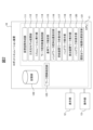
- FIG. 2 is a functional block diagram of the robot simulation device.
- 13 is a flowchart of a simulation of a workpiece removal operation in which three-dimensional models of the workpieces are gripped and transferred all at once.
- 1 is a diagram showing a three-dimensional model of the robot system displayed on a display screen by a three-dimensional model placement unit.
- FIG. A figure for explaining a first example regarding the quantity of work models to be grasped at once and the specification of a reference work model.
- FIG. 13 is a diagram showing a simulation screen in which the three-dimensional model of the robot has been moved to the three-dimensional model of the supply device.
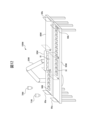
- FIG. 13 is a diagram showing a simulation screen in which three-dimensional models of a plurality of workpieces are gripped collectively by a three-dimensional model of a hand.
- FIG. 13 is a diagram showing a simulation screen in which a three-dimensional model of the robot is moved to a three-dimensional model of the discharge device.
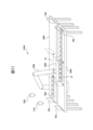
- FIG. 13 is a diagram showing a simulation screen in which three-dimensional models of a plurality of workpieces are placed on a three-dimensional model of a discharge device by the three-dimensional model of a hand.
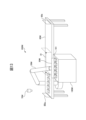
- FIG. 13 is a diagram showing a simulation screen in which a three-dimensional model of a hand is used to place a plurality of workpieces on a fixed table serving as a discharge device.
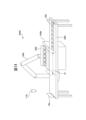
- FIG. 13 is a diagram showing a simulation screen in which a three-dimensional model of a hand simultaneously grasps three-dimensional models of a plurality of workpieces from a fixed table serving as a supply device.
- FIG. 1 is a diagram showing an example of a robot simulation device 10 according to an embodiment.
- FIG. 2 is a functional block diagram of the robot simulation device 10.
- the robot simulation device 10 is configured with an information processing device such as a personal computer or a tablet terminal.
- the robot simulation device 10 provides a function for executing a simulation of an operation in which three-dimensional models of multiple workpieces on a supply device that supplies the workpieces are grasped collectively by a three-dimensional model of a hand mounted on a three-dimensional model of a robot.
- the device that supplies the workpiece to the robot is referred to as the supply device, and the device to which the workpiece picked up by the robot is transferred is referred to as the discharge device.
- the supply device may be a transport device such as a belt conveyor, or a fixed stand such as a table.
- the discharge device may also be a transport device such as a belt conveyor, or a fixed stand such as a table.
- simulation includes not only simulating the operation of a three-dimensional model of each device on a display screen (virtual space), but also performing numerical calculations of the position and orientation of the robot and other devices.
- the robot simulation device 10 comprises a display unit 12 that displays various images related to the simulation, and an operation unit 13 through which the operator inputs various operations.
- the display unit 12 comprises, for example, a liquid crystal display.
- the operation unit 13 comprises, for example, input devices such as a keyboard, mouse, and touch pad.
- Three-dimensional models of robots and the like are stored in a storage device 14 (FIG. 2).
- the robot simulation device 10 may have a configuration as a general computer in which memory (ROM, RAM, non-volatile memory, etc.), display unit 12, operation unit 13, storage device (HDD, etc.), network interface, various input/output interfaces, etc. are connected to a CPU 11 (FIG. 2).
- the robot simulation device 10 includes a virtual space creation unit 111, a three-dimensional model placement unit 112, a simulation execution unit 113, a workpiece gripping quantity designation unit 114, a reference workpiece designation unit 115, a handwork gripping position setting unit 116, a supply device workpiece non-display unit 117, a handwork display unit 118, a discharge device workpiece display unit 119, and a handwork non-display unit 120.
- the robot simulation device 10 may further include a fixed table workpiece placement position setting unit 121.
- the robot simulation device 10 may further include a workpiece interval designation unit 123.
- the robot simulation device 10 includes a storage unit 122.
- the storage unit 122 may be configured, for example, with a storage device such as a non-volatile memory or a HDD.
- the storage unit 122 stores three-dimensional models and positioning information of each object that constitutes the robot system model, various setting information required for performing a simulation, and the like.
- the virtual space creation unit 111 generates a virtual space in which to place three-dimensional models of various objects that make up the robot system model within the memory space of the robot simulation device 10.
- the three-dimensional model placement unit 112 places a three-dimensional model of the robot, a three-dimensional model of the transport device, a three-dimensional model of the workpiece, a three-dimensional model of the detection device, and a three-dimensional model of the fixed base in a virtual space based on the placement information of the various objects that make up the robot system model.
- the simulation execution unit 113 is responsible for the function of simulating the operation of picking up a workpiece on the supply device and transferring it to the discharge device using a three-dimensional model of the robot.
- the functions of the simulation execution unit 113 include a function of numerically calculating the position and orientation of the three-dimensional models of the robot and various objects, and a function of simulating the operation of the three-dimensional models of the robot and various objects.
- the simulation execution unit 113 may be configured to control each functional block involved in the execution of the simulation (handwork gripping position setting unit 116, supply device work non-display unit 117, handwork display unit 118, discharge device work display unit 119, handwork non-display unit 120, and fixed table work placement position setting unit 121).
- the workpiece grip quantity designation unit 114 provides a function for designating the number of workpieces to be gripped collectively by the three-dimensional model of the hand.
- the workpiece grip quantity designation unit 114 may be configured to accept an input for setting the number of workpieces to be gripped collectively by the three-dimensional model of the hand via a setting screen (user interface). Alternatively, the workpiece grip quantity designation unit 114 may receive an input of the number of workpieces to be gripped collectively from an external device.
- the reference work designation unit 115 provides a function for designating a work that serves as a reference when a three-dimensional model of a work is grasped by a three-dimensional model of a hand.
- the reference work designation unit 115 may be configured to accept an input for designating a work that serves as a reference when a three-dimensional model of a work is grasped by a three-dimensional model of a hand via a setting screen (user interface).
- the reference work designation unit 115 may receive an input for designating a three-dimensional model of a work that serves as a reference from an external device.
- the hand work gripping position setting unit 116 provides a function for setting the position of the three-dimensional model of the work with respect to the three-dimensional model of the hand when gripping the three-dimensional model of the work with the three-dimensional model of the hand.
- the supply device workpiece non-display unit 117 provides a function for hiding the three-dimensional model of the workpiece on the three-dimensional model of the supply device.
- the hand work display unit 118 provides the function of displaying a three-dimensional model of the work on a three-dimensional model of the hand.
- the discharge device work display unit 119 has the function of displaying a three-dimensional model of the work on a three-dimensional model of the discharge device.
- the hand work hiding unit 120 has the function of hiding the three-dimensional model of the work on the three-dimensional model of the hand.
- the supply device work non-display unit 117, the hand work display unit 118, the discharge device work display unit 119, and the hand work non-display unit 120 may be configured to cooperate with the simulation execution unit 113 and provide their functions in response to instructions from the simulation execution unit 113.
- the fixed table work placement position setting unit 121 provides a function for setting the placement position of the three-dimensional model of the workpiece relative to the three-dimensional model of the fixed table when the fixed table is used as the discharge device.
- the work spacing designation unit 123 provides a function for designating the spacing between the three-dimensional models of multiple workpieces placed on the supply device.
- the work spacing designation unit 123 may be configured to receive an input designating the spacing between the three-dimensional models of the workpieces via a setting screen (user interface). Alternatively, the work spacing designation unit 123 may receive an input designating the spacing between the three-dimensional models of the workpieces from an external device.
- FIG. 3 is a flowchart of a simulation of an operation for gripping and transferring a three-dimensional model of a workpiece as a whole (hereinafter referred to as a workpiece removal operation) that is executed on the robot simulation device 10.
- the workpiece removal operation shown in FIG. 3 is executed under the control of the CPU 11 of the robot simulation device 10.
- the three-dimensional model placement unit 112 places a three-dimensional model of the robot system, including a three-dimensional model of the robot, in a virtual space (step S1). Then, the three-dimensional model placement unit 112 displays the three-dimensional model of the robot system placed in the virtual space on the display screen of the display unit 12 (step S2).
- FIG. 4 shows a three-dimensional model of the robot system (hereinafter referred to as the robot system model 100M) displayed on the display screen by the three-dimensional model placement unit 112.
- the robot system model 100M includes a three-dimensional model of the robot (hereinafter referred to as the robot model 20M), a three-dimensional model of the hand (hereinafter referred to as the hand model 30M), a three-dimensional model of the transport device as a supply device (hereinafter referred to as the transport device model 80M), a three-dimensional model of the work (hereinafter referred to as the work model WM), three-dimensional models of two detection devices (hereinafter referred to as the detection device models 70M and 71M), and a three-dimensional model of the transport device as a discharge device (hereinafter referred to as the transport device model 90M).
- the transport device is, for example, a belt conveyor.
- a vertical articulated robot model is used as the robot model 20M, but models of other types of robots, such as a horizontal articulated robot or a parallel link type robot, may also be used.
- Hand model 30M is, for example, a model of a suction hand, and has multiple suction parts for gripping multiple workpieces at once.
- a three-dimensional model of another type of hand device capable of gripping multiple workpieces at once may also be used as hand model 30M.
- the transport device model 80M transports the workpiece model WM at a constant speed from upstream to downstream in the workpiece supply range between the upstream end 80a and the downstream end 80b.
- the robot model 20M operates to grasp the workpiece model WM by following the movement of the workpiece model WM transported by the transport device model 80M within a following operation range (indicated by the dashed arrow 81) virtually defined on the transport device model 80M.
- the transport device model 90M can transport the workpiece model WM at a constant speed from upstream to downstream in the workpiece supply range between the upstream end 90a and the downstream end 90b.
- the robot model 20M operates to place the workpiece model WM on the transport device model 90M by following the movement of the transport device model 90M within a following operation range (indicated by the dashed arrow 91) virtually defined on the transport device model 90M.
- the setting information for the transport device models 80M and 90M may be set in advance in the storage unit 122, or may be set by an operator for the robot simulation device 10.
- the robot simulation device 10 transports the workpiece model WM based on the setting information for the transport device models 80M and 90M.
- Each of the detection device models 70M and 71M is a model of a visual sensor.
- the visual sensor may be a camera that captures grayscale images or color images, or a stereo camera or a three-dimensional sensor that can obtain distance images or three-dimensional point clouds.
- the positional relationship between the detection device models 70M and 71M and the robot model 20M is assumed to be known.
- the detection device model 70M is arranged so that the vicinity of the upstream end of the transport device model 80M is included in the imaging range.
- the detection device model 70M provides a function to detect the position of the workpiece model WM that is transported to the upstream end of the transport device model 80M by image processing of the captured image.
- the detection device model 71M may have a function to detect and check the workpiece model WM flowing on the transport device model 90M.
- the detection results by the detection device models 70M and 71M can be used in a simulation by the simulation execution unit 113.
- the workpiece gripping quantity designation unit 114 accepts designation of the quantity of workpiece models WM to be gripped collectively by the hand model 30M (step S3).
- the reference workpiece designation unit 115 accepts designation of the workpiece model that will be the reference when gripping collectively by the hand model 30M (step S4).
- the reference workpiece model is a workpiece model that is used as a reference when detecting the workpiece model to be gripped and calculating the position. The operator can designate a specific workpiece model that is transported onto the transport device model 80M as the "reference workpiece model.”
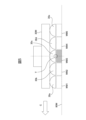
- FIG. 5 is a diagram for explaining a first example regarding the number of work models to be gripped collectively and the designation of a reference work model.
- the hand model 30M is of a type having five suction portions (30a, 30b, 30c, 30d, 30e) as shown in FIG. 5, the number of work models to be gripped collectively by the hand model 30M may be designated as five.
- the arrow C indicates the upstream side of the conveying device model 80M in the conveying direction.
- the operator may designate the nth work model from the upstream among the multiple work models WM that are continuously conveyed on the conveying device model 80M as the reference work model.
- FIG. 5 shows a case in which the third work model from the upstream (work model WM3) is designated as the reference work model among the five work models WM1 to WM5 flowing on the conveying device model 80M.
- the robot model 20M may, for example, operate to grasp the reference work model WM3 at the position of the tool tip point T set on the hand model 30M.
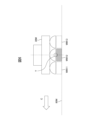
- FIG. 6 is a diagram for explaining a second example regarding the number of work models to be grasped collectively and the designation of a reference work. If the hand model 30M is a type having three suction parts as shown in FIG. 6, the number of work models to be grasped collectively by the hand model 30M may be designated as three.
- FIG. 6 shows a case in which the second from the upstream (work model WM12) of the three work models WM11 to WM13 flowing continuously on the transport device model 80M is designated as the reference work model.
- the robot model 20M may operate to grasp the reference work model WM12 at the position of the tool tip point T set on the hand model 30M, for example.
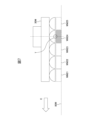
- FIG. 7 is a diagram for explaining a third example regarding the number of work models to be grasped collectively and the designation of a reference work. If the hand model 30M is of a type having five suction portions as shown in FIG. 7, the number of work models to be grasped collectively by the hand model 30M may be designated as five.
- FIG. 7 shows a case in which the fourth work model from the upstream (work model WM24) of the five work models WM21 to WM25 that flow continuously on the transport device model 80M is designated as the reference work model.
- the robot model 20M may operate to grasp the reference work model WM24 at the position of the tool tip point T set on the hand model 30M, for example.
- the handwork gripping position setting unit 116 (a1) The number of work models WM to be collectively grasped, (a2) A reference work model WM, (a3) the interval between the workpiece models WM transported along the transport device model 80M, and (a4) The position and posture of the robot model 20M when moving onto the transport device model 80M, Based on this, "the position of each work model WM with respect to the hand model 30M when the work model WM is gripped by the hand model 30M" is set (step S5).
- (a1) the number of workpiece models WM to be grasped collectively” and "(a2) the reference workpiece model WM” are set in steps S3 and S4 above.
- “(a3) The interval between the workpiece models WM to be transported along the transport device model 80M” specifies the interval d in the transport direction between the workpiece models WM arranged consecutively in the transport direction on the transport device model 80M as shown in FIG. 8. It is assumed that multiple workpiece models are transported at equal intervals. The operator may set the interval d to be equal to the interval between the multiple suction parts of the hand model 30M via the setting function provided by the workpiece interval designation unit 123.
- This interval d makes it possible to obtain the positions on the transport device model 80M of other workpiece models WM (workpiece models WM1-2 and WM4-5 in FIG. 8) based on the position of the reference workpiece model WM (workpiece model WM3 in FIG. 8).
- the "(a3) interval between the workpiece models WM transported along the transport device model 80M" may be preset in the memory unit 122.
- the simulation execution unit 113 may obtain "(a4) the position and posture of the robot model 20M when moving over the transport device model 80M" based on, for example, the following operation model.
- the robot model 20M starts operating from a predetermined waiting position in response to receiving a detection signal from the detection device model 70M detecting that the reference work model WM has been placed on the transport device model 80M.
- the robot model 20M moves within the following operation range (the range indicated by the arrow 81 in FIG. 4) so as to be able to follow the movement of the reference workpiece model WM in the transport direction (i.e., the transport speed of the transport device model 80M).
- the handwork gripping position setting unit 116 can determine the position and orientation of the robot model 20M when it is positioned at a position where it can grip multiple work models, including the reference work model WM, all at once, as "(a4) the position and orientation of the robot model 20M when moving onto the transport device model 80M.”
- the handwork gripping position setting unit 116 calculates the "position of each workpiece model WM relative to the hand model 30M when gripping the workpiece model WM with the hand model 30M" based on the "(a4) position and orientation of the robot model 20M when moving onto the transport device model 80M” obtained as described above.
- the position of the tool tip point T is known.
- the position of the reference workpiece model WM in the virtual space can be obtained from the detection result by the detection device model 70M and information such as the transport speed of the transport device model 80M.
- the interval d of the workpiece models WM is known.
- the handwork gripping position setting unit 116 can calculate the "position of each workpiece model WM relative to the hand model 30M when gripping the workpiece model WM with the hand model 30M" based on the information (a1) to (a4) above.
- "the position of each work model WM relative to the hand model 30M when the work model WM is grasped by the hand model 30M” can also be expressed as "the grasping position of the work model WM relative to the hand model 30M.”
- step S1 to S5 the "position of each work model WM relative to the hand model 30M when the hand model 30M grasps the work model WM" is calculated and set in the robot simulation device 10. This makes it possible to display the operation of the robot model 20M grasping multiple work models WM together on the simulation screen. The operator can check whether the robot model 20M can correctly reach a position where it can grasp the work models WM together, modify various settings as necessary, and create an appropriate program.
- the user can cause the robot simulation device 10 to execute an advanced simulation of gripping multiple work models at once, by simply inputting the above setting items (a1) to (a3).
- this embodiment establishes a setting method that is useful to the user for simulating the operation of the robot model 20M gripping multiple work models WM at once.
- the robot simulation device 10 can further perform the operations shown in steps S6-S7 by using the "position of each work model WM relative to the hand model 30M when the hand model 30M grasps the work model WM.”
- step S6 the robot simulation device 10 moves the robot model 20M onto the transport device model 80M based on "(a4) Position and posture of the robot model 20M when moving onto the transport device model 80M” and "Position of each work model WM relative to the hand model 30M when the hand model 30M grasps the work model WM", and executes an operation of grasping the work models WM collectively with the hand model 30M.
- the simulation execution unit 113 moves the robot model 20M so that it assumes "(a4) Position and posture of the robot model 20M when moving onto the transport device model 80M".
- the supply device workpiece non-display unit 117 makes the workpiece models WM that are grasped collectively by the hand model 30M invisible on the transport device model 80M. Furthermore, the hand work display unit 118 displays the workpiece models WM on the hand model 30M. The hand work display unit 118 can display the workpiece models WM on the hand model 30M according to the "position of each workpiece model WM relative to the hand model 30M when the hand model 30M grasps the workpiece model WM".
- Figure 10 is a simulation screen showing the state in which the workpiece model WM has moved to the hand model 30M side after these processes. Note that Figure 10 shows the state in which the robot model 20M is in a position slightly upward from the position where it grasps the workpiece model WM.
- the above operations represent the operation of the robot model 20M, which grasps multiple workpiece models WM transported on the transport device model 80M collectively with the hand model 30M, in the virtual space (display screen).
- step S7 the robot simulation device 10 moves the robot model 20M onto the transport device model 90M based on "(a4) Position and posture of the robot model 20M when moving onto the transport device model 80M” and "position of each workpiece model WM relative to the hand model 30M when the hand model 30M grasps the workpiece model WM", and performs an operation of placing the workpiece model WM on the transport device model 90M.
- the simulation execution unit 113 moves the robot model 20M onto the transport device model 90M based on "(a4) Position and posture of the robot model 20M when moving onto the transport device model 80M".
- the simulation execution unit 113 performs, for example, (k11) From the position and posture of the robot model 20M gripping the workpiece model WM as shown in FIG. 9, (k12) so that the workpiece model WM can be placed on the conveying surface while following the conveying speed of the conveying device model 90M within the following operation range (arrow 91) of the conveying device model 90M, The robot model 20M is operated.
- the discharge device work display unit 119 displays the work model WM placed on the transport device model 90M on the discharge side.
- the discharge device work display unit 119 can position the work model WM on the transport device model 90M according to "the position of each work model WM relative to the hand model 30M when the hand model 30M grasps the work model WM".
- the hand work non-display unit 120 hides the work model WM on the hand model 30M.
- Figure 12 is a simulation screen showing the state in which the work model WM has moved to the transport device model 90 side after these processes.
- the above operations allow the operation of the robot system model 100M, which uses the hand model 30M to move multiple workpiece models WM all at once from the supply-side conveyor model 80M to the discharge-side conveyor model 90M, to be represented in a virtual space (display screen).
- the above-described workpiece removal operation makes it possible to simulate a robot system in which a hand model simultaneously grasps multiple workpiece models being transported on a transport device model.
- Modification 1 described here is a configuration example in which the discharge device is a fixed base.
- Fig. 13 shows the configuration of a robot system model 200M according to modification 1.
- the robot system model 200M includes a fixed base model 190M as the discharge device.
- the same components as those in the robot system model 100M in the above embodiment are denoted by the same reference numerals, and their description will be omitted or simplified.
- the robot simulation device 10 executes the processes of steps S1 to S5 of the above-mentioned workpiece removal operation (FIG. 3), and calculates and sets "the position of each workpiece model WM relative to the hand model 30M when the workpiece model WM is grasped by the hand model 30M.”
- the fixed table workpiece placement position setting unit 121 is The position of each work model WM relative to the hand model 30M when the work model WM is gripped by the hand model 30M, and The position and orientation of the robot model 20M when moving onto the fixed base model 190M, Based on this, the placement position of the workpiece model WM with respect to the fixed base model 190M is set.
- the simulation execution unit 113 may obtain the "position and posture of the robot model 20M when moving over the fixed base model 190M" based on, for example, the following operation model. (k21) From the position and posture of the robot model 20M gripping the workpiece model WM as shown in FIG. 9, (k22) The fixed base model 190M is moved to a standby position above the placement surface 191, and then descends from there to approach the placement surface 191 so that all of the work models WM can be placed thereon. The robot model 20M is operated.
- the fixed base work placement position setting unit 121 can determine the "position and orientation of the robot model 20M when it moves onto the fixed base model 190M.”
- the "placement position of the work model WM relative to the fixed base model 190M” is obtained from the “position and orientation of the robot model 20M when it moves onto the fixed base model 190M” and the "position of each work model WM relative to the hand model 30M when the hand model 30M grasps the work model WM.”
- the fixed base work placement position setting unit 121 can represent, as a simulation image, the operation of placing the work model WM grasped by the robot model 20M on the fixed base model 190M, as shown in FIG. 13.
- the robot simulation device 10 may also perform operations equivalent to steps S6 and S7 in the above-described workpiece removal operation. That is, when the hand model 30M reaches a position on the transport device model 80M where it grasps the worm model WM, the supply device workpiece non-display unit 117 makes the workpiece model WM invisible on the transport device model 80M. Then, the hand workpiece display unit 118 displays the workpiece model WM on the hand model 30M.
- the hand work non-display unit 120 hides the work model WM on the hand model 30M. Then, the discharge device work display unit 119 displays the work model WM at the placement position of the work model WM.
- This provides a simulation image of the state of the workpiece model WM being grasped on the transport device model 80M and transferred onto the fixed base model 190M.
- Fig. 14 shows the configuration of a robot system model 300M according to the second modification.
- the robot system model 300M includes a fixed base model 180M as the supply device.
- the same components as those in the robot system model 100M in the above-described embodiment are given the same reference numerals, and their description will be omitted or simplified.
- the robot simulation device 10 can also simulate the operation in which the supply device is a fixed base and the discharge device is a transport device.
- the three-dimensional model placement unit 112 places the robot system model 300M, which includes the robot model 20M, in the virtual space and displays it on the display screen.
- the workpiece grasping quantity designation unit 114 accepts the designation of the quantity of workpiece models to be grasped at once.
- the reference work designation unit 115 also accepts the designation of the reference work model.
- the user may designate a specific work model placed on the fixed base model 180M as the reference work model.
- the robot simulation device 10 includes: (b1) The number of workpiece models to be collectively grasped; (b2) a reference work model; (b3) The distance between the work models; (b4) The position and posture of the robot model 20M when moving to the fixed base model 190M, Based on this, "the position of each work model WM with respect to the hand model 30M when the work model WM is grasped by the hand model 30M" is set.
- the spacing between the multiple suction pads of the hand model 30M may be set in the same manner as described with reference to FIG. 8.
- the simulation execution unit 113 may obtain "(b4) the position and posture of the robot model 20M when moving to the fixed base model 190M" using, for example, the following motion model.
- the robot model 20M moves from a predetermined standby position to an approach start position above the workpiece model WM on the fixed base model 190M.
- the robot model 20M descends from the approach start position, and moves to a position where it can grasp the workpiece model WM.
- the robot model 20M may operate to grip the reference work model WM with the suction portion located at the position of the tool tip point T of the hand model 30M.
- the handwork gripping position setting unit 116 can obtain the position and orientation of the robot model 20M when it is positioned on the fixed base model 190M at a position where it can grip the workpiece model WM as "(b4) Position and orientation of the robot model 20M when moving to the fixed base model 190M.”
- the handwork gripping position setting unit 116 calculates the "position of each workpiece model WM relative to the hand model 30M when gripping the workpiece model WM with the hand model 30M" based on the "(b4) position and orientation of the robot model 20M when moving to the fixed base model 190M” obtained as described above.
- the position of the tool tip point T is known.
- the handwork gripping position setting unit 116 can calculate the "position of each workpiece model WM relative to the hand model 30M when gripping the workpiece model WM with the hand model 30M" based on the information from (b1) to (b4) above.
- the robot simulation device 10 can also simulate the operation of moving the robot model 20M onto the transport device model 90M based on "(b4) Position and posture of the robot model 20M when moving to the fixed base model 190M" and "Position of each workpiece model WM relative to the hand model 30M when the hand model 30M grasps the workpiece model WM.”
- the simulation execution unit 113 can, for example, (k41) From the position and posture in which the robot model 20M grasps the workpiece model WM as shown in FIG. 14, (k42) so that the workpiece model WM can be placed on the conveying surface while following the conveying speed of the conveying device model 90M within the following operation range (arrow 91) of the conveying device model 90M, The robot model 20M is operated.
- the above allows for a simulation of the operation of gripping multiple work models WM on the fixed base model 190M all at once with the hand model 30M and moving them to the discharge device.
- the functional blocks of the robot simulation device described with reference to FIG. 2 may be realized by the CPU of the robot simulation device executing various software stored in a storage device, or may be realized by a hardware-based configuration such as an ASIC (Application Specific Integrated Circuit).
- ASIC Application Specific Integrated Circuit
- the programs for executing various processes such as the workpiece removal operation ( Figure 3) in the above-mentioned embodiment can be recorded on various computer-readable recording media (e.g., semiconductor memory such as ROM, EEPROM, flash memory, magnetic recording media, and optical disks such as CD-ROM and DVD-ROM).
- semiconductor memory such as ROM, EEPROM, flash memory, magnetic recording media, and optical disks such as CD-ROM and DVD-ROM.
- this embodiment it is possible to display in a virtual space (display screen) the operation of a robot system that collectively grips three-dimensional models of multiple workpieces on a three-dimensional model of a supply device with a three-dimensional model of a hand.
- a setting method that is useful to the user for simulating a robot system that collectively grips three-dimensional models of multiple workpieces on a three-dimensional model of a supply device with a three-dimensional model of a hand.
- (Appendix 1) a three-dimensional model arrangement unit (112) that arranges in a virtual space a three-dimensional model of a robot, a three-dimensional model of a hand mounted on the robot, a three-dimensional model of a supply device, a three-dimensional model of a discharge device, a three-dimensional model of a workpiece, and a three-dimensional model of a detection device that detects the workpiece on the supply device; a workpiece grasp quantity designation unit (114) that receives an input that designates the quantity of the three-dimensional models of the workpiece to be grasped collectively by the three-dimensional model of the hand; and an input that designates the three-dimensional model of the workpiece that serves as a reference when the three-dimensional model of the workpiece is grasped by the three-dimensional model of the hand.
- the robot simulation device (10) includes a reference work designation unit (115) and a gripping position setting unit (116) that sets a gripping position of the three-dimensional model of the work with respect to the three-dimensional model of the hand when gripping the three-dimensional model of the work with the three-dimensional model of the hand, based on the specified quantity of the three-dimensional models of the work to be gripped collectively, the three-dimensional model of the reference work, the spacing of the three-dimensional model of the work on the three-dimensional model of the supply device, and the position and posture of the three-dimensional model of the robot when moving onto the three-dimensional model of the supply device.
- the robot simulation device (10) described in Appendix 1 further includes a simulation execution unit (113) that executes an operation of moving the three-dimensional model of the robot to the three-dimensional model of the supplying device and gripping the three-dimensional model of the workpiece collectively with the three-dimensional model of the hand, based on a position and posture of the three-dimensional model of the robot when it moves over the three-dimensional model of the supplying device and a gripping position of the three-dimensional model of the workpiece relative to the three-dimensional model of the hand.
- a simulation execution unit (113) that executes an operation of moving the three-dimensional model of the robot to the three-dimensional model of the supplying device and gripping the three-dimensional model of the workpiece collectively with the three-dimensional model of the hand, based on a position and posture of the three-dimensional model of the robot when it moves over the three-dimensional model of the supplying device and a gripping position of the three-dimensional model of the workpiece relative to the three-dimensional model of the hand.
- the simulation execution unit (113) is a robot simulation device (10) described in Appendix 2, which moves the three-dimensional model of the robot to the three-dimensional model of the supply device, hides the three-dimensional model of the work on the three-dimensional model of the supply device, and displays the three-dimensional model of the work on the three-dimensional model of the hand.
- the simulation execution unit (113) is a robot simulation device (10) described in Appendix 2 or 3, which moves the three-dimensional model of the robot to the three-dimensional model of the discharge device and performs an operation of placing the three-dimensional model of the work on the discharge device based on the position and posture of the three-dimensional model of the robot when it moves over the three-dimensional model of the supply device and the gripping position of the three-dimensional model of the work relative to the three-dimensional model of the hand.
- the simulation execution unit (113) is a robot simulation device (10) described in Appendix 4, which moves the three-dimensional model of the robot to the three-dimensional model of the discharge device, displays the three-dimensional model of the workpiece on the three-dimensional model of the discharge device, and hides the three-dimensional model of the workpiece on the three-dimensional model of the hand.
- the robot simulation device (10) according to any one of appendices 1 to 5, wherein the workpiece grip quantity designation unit (114) accepts a user input for designating the quantity to be gripped collectively.
- the reference work designation unit (115) is a robot simulation device (10) according to any one of appendices 1 to 6, which accepts a user input for designating the reference work.
- a three-dimensional model arrangement unit (112) that arranges in a virtual space a three-dimensional model of a robot, a three-dimensional model of a hand mounted on the robot, a three-dimensional model of a supplying device, a three-dimensional model of a discharging device, a three-dimensional model of a workpiece, and a three-dimensional model of a detection device that detects the workpiece on the supplying device; a quantity of the three-dimensional models of the workpieces to be grasped collectively by the three-dimensional model of the hand, a three-dimensional model of the workpiece that serves as a reference when the three-dimensional model of the workpiece is grasped by the three-dimensional model of the hand, a distance between the three-dimensional models of the workpieces on the three-dimensional model of the supplying device, a position and orientation of the three-dimensional model of the robot when moving onto the three-dimensional model of the supplying device, and the three-dimensional model of the hand and a simulation execution unit
- Robot simulation device 11 CPU 12 Display unit 13 Operation unit 111 Virtual space creation unit 112 Three-dimensional model arrangement unit 113 Simulation execution unit 114 Workpiece grip quantity designation unit 115 Reference workpiece designation unit 116 Hand workpiece grip position setting unit 117 Supply device workpiece non-display unit 118 Hand workpiece display unit 119 Discharge device workpiece display unit 120 Hand workpiece non-display unit 121 Fixed base workpiece placement position setting unit 122 Memory unit 123 Workpiece interval designation unit 20M Robot model 30M Hand model 70M, 71M Detection device model 80M, 90M Transport device model WM Workpiece model 180M, 190M Fixed base model 191 Placement surface 100M, 200M, 300M Robot system model
Landscapes
- Engineering & Computer Science (AREA)
- Robotics (AREA)
- Mechanical Engineering (AREA)
- Manipulator (AREA)
- Numerical Control (AREA)
Abstract
Description
(a1)一括して把持するワークモデルWMの数量、
(a2)基準となるワークモデルWM、
(a3)搬送装置モデル80Mに沿って搬送されるワークモデルWMの間隔、および
(a4)搬送装置モデル80M上に移動する際のロボットモデル20Mの位置姿勢、
に基づいて、「ハンドモデル30MでワークモデルWMを把持する際のハンドモデル30Mに対する各ワークモデルWMの位置」を設定する(ステップS5)。
(k1)ロボットモデル20Mは、基準となるワークモデルWMが搬送装置モデル80M上に投入されたことを検出した検出信号を検出装置モデル70Mから受信することに応じ、所定の待機位置から動作を開始する。
(k2)ロボットモデル20Mは、追従動作範囲(図4の矢印81で示す範囲)内で、基準となるワークモデルWMの搬送方向への動き(すなわち、搬送装置モデル80M搬送速度)に追従できるように移動する。
(k3)追従動作範囲においてロボットモデル20MがワークモデルWMの動きに追従している状態では、互いの相対速度はゼロの状態になる。この状態において、搬送速度で動く動的な座標系を仮定すると、ロボットモデル20Mは、静止しているワークモデルに対して上方から下降して接近して把持するように動作を行うことができる。
(k4)上記動作において、ロボットモデル20Mは、ハンドモデル30Mのツール先端点Tの位置にある吸着部で基準となるワークモデルWMを把持するように動作しても良い。
(k11)ロボットモデル20Mが図9のようにワークモデルWMを把持する位置姿勢から、
(k12)搬送装置モデル90Mの追従動作範囲(矢印91)内で搬送装置モデル90Mの搬送速度に追従しながらワークモデルWMを搬送面に置くことができるように、
ロボットモデル20Mを動作させる。
ここで説明する変形例1は、排出装置が固定台である場合の構成例である。図13は、変形例1に係るロボットシステムモデル200Mの構成を表している。ロボットシステムモデル200Mは、排出装置として固定台モデル190Mを備える。図13において上述の実施形態におけるロボットシステムモデル100Mと同一の構成要素には同一の符号を付し、その説明は省略或いは簡略化する。
・ハンドモデル30MでワークモデルWMを把持する際のハンドモデル30Mに対する各ワークモデルWMの位置、及び、
・固定台モデル190M上に移動する際のロボットモデル20Mの位置姿勢、
に基づいて、固定台モデル190Mに対するワークモデルWMの配置位置を設定する。
(k21)ロボットモデル20Mが図9のようにワークモデルWMを把持する位置姿勢から、
(k22)固定台モデル190Mの載置面191の上方の待機位置に移動し、そこから下降し載置面191に接近して全てのワークモデルWMを置くことができるように、
ロボットモデル20Mを動作させる。
次に変形例2として、供給装置が固定台であり、排出装置が搬送装置である場合の構成について図14を参照して説明する。図14は、変形例2に係るロボットシステムモデル300Mの構成を表している。ロボットシステムモデル300Mは、供給装置として固定台モデル180Mを備える。図14において上述の実施形態におけるロボットシステムモデル100Mと同一の構成要素には同一の符号を付し、その説明は省略或いは簡略化する。ロボットシミュレーション装置10は、供給装置が固定台であり、排出装置が搬送装置である場合の動作もシミュレーションすることができる。
(b1)一括して把持するワークモデルの数量、
(b2)基準となるワークモデル、
(b3)ワークモデル同士の間隔、
(b4)固定台モデル190Mに移動する際のロボットモデル20Mの位置姿勢、
に基づき、「ハンドモデル30MでワークモデルWMを把持する際のハンドモデル30Mに対する各ワークモデルWMの位置」を設定する。
(k31)ロボットモデル20Mは所定の待機位置から、固定台モデル190M上のワークモデルWMの上方の接近開始位置に移動する。
(k32)ロボットモデル20Mは接近開始位置から下降し、ワークモデルWMを把持可能な位置に移動する。
(k33)上記動作において、ロボットモデル20Mは、ハンドモデル30Mのツール先端点Tの位置にある吸着部で基準となるワークモデルWMを把持するように動作しても良い。
(k41)ロボットモデル20Mが図14のようにワークモデルWMを把持する位置姿勢から、
(k42)搬送装置モデル90Mの追従動作範囲(矢印91)内で搬送装置モデル90Mの搬送速度に追従しながらワークモデルWMを搬送面に置くことができるように、
ロボットモデル20Mを動作させる。
(付記1)
ロボットの三次元モデル、前記ロボットに搭載されたハンドの三次元モデル、供給装置の三次元モデル、排出装置の三次元モデル、ワークの三次元モデル、及び前記供給装置上の前記ワークを検出する検出装置の三次元モデルを仮想空間に配置する三次元モデル配置部(112)と、前記ハンドの三次元モデルにより前記ワークの三次元モデルを一括して把持する数量を指定する入力を受け付けるワーク把持数量指定部(114)と、前記ワークの三次元モデルを前記ハンドの三次元モデルにより把持する際の基準となるワークの三次元モデルを指定する入力を受け付ける基準ワーク指定部(115)と、指定された前記一括して把持する前記ワークの三次元モデルの数量、前記基準となるワークの三次元モデル、前記供給装置の三次元モデル上における前記ワークの三次元モデルの間隔、及び前記供給装置の三次元モデル上に移動する際の前記ロボットの三次元モデルの位置姿勢に基づいて、前記ハンドの三次元モデルモデルで前記ワークの三次元モデルを把持する際の前記ハンドの三次元モデルに対する前記ワークの三次元モデルの把持位置を設定する把持位置設定部(116)と、を備えるロボットシミュレーション装置(10)である。
(付記2)
前記供給装置の三次元モデル上に移動する際の前記ロボットの三次元モデルの位置姿勢、及び前記ハンドの三次元モデルに対する前記ワークの三次元モデルの把持位置に基づいて、前記ロボットの三次元モデルを前記供給装置の三次元モデルに移動させ、前記ワークの三次元モデルを前記ハンドの三次元モデルにより一括して把持する動作を実行させるシミュレーション実行部(113)を更に備える、付記1に記載のロボットシミュレーション装置(10)である。
(付記3)
前記シミュレーション実行部(113)は、前記ロボットの三次元モデルを前記供給装置の三次元モデルに移動させ、前記供給装置の三次元モデル上で前記ワークの三次元モデルを非表示にし、前記ハンドの三次元モデル上で前記ワークの三次元モデルを表示させる、付記2に記載のロボットシミュレーション装置(10)である。
(付記4)
前記シミュレーション実行部(113)は、前記供給装置の三次元モデル上に移動する際の前記ロボットの三次元モデルの位置姿勢、及び前記ハンドの三次元モデルに対する前記ワークの三次元モデルの把持位置に基づいて、前記ロボットの三次元モデルを前記排出装置の三次元モデルに移動させ、前記ワークの三次元モデルを前記排出装置上に載置する動作を行わせる、付記2又は3に記載のロボットシミュレーション装置(10)である。
(付記5)
前記シミュレーション実行部(113)は、前記ロボットの三次元モデルを前記排出装置の三次元モデルに移動させ、前記排出装置の三次元モデル上で前記ワークの三次元モデルを表示させ、前記ハンドの三次元モデル上で前記ワークの三次元モデルを非表示にする、付記4に記載のロボットシミュレーション装置(10)である。
(付記6)
前記ワーク把持数量指定部(114)は、前記一括して把持する数量を指定するためのユーザ入力を受け付ける、付記1から5のいずれか一項に記載のロボットシミュレーション装置(10)である。
(付記7)
前記基準ワーク指定部(115)は、前記基準となるワークを指定するためのユーザ入力を受け付ける、付記1から6のいずれか一項に記載のロボットシミュレーション装置(10)である。
(付記8)
前記供給装置の三次元モデル上における前記ワークの三次元モデルの間隔を指定する入力を受け付けるワーク間隔指定部(123)を更に備える、付記1から7のいずれか一項に記載のロボットシミュレーション装置(10)である。
(付記9)
前記供給装置は搬送装置であり、前記排出装置は搬送装置である、付記1から8のいずれか一項に記載のロボットシミュレーション装置(10)である。
(付記10)
前記供給装置は搬送装置であり、前記排出装置は固定台である、付記1から8のいずれか一項に記載のロボットシミュレーション装置(10)である。
(付記11)
前記供給装置は固定台であり、前記排出装置は搬送装置である、付記1から8のいずれか一項に記載のロボットシミュレーション装置(10)である。
(付記12)
ロボットの三次元モデル、前記ロボットに搭載されたハンドの三次元モデル、供給装置の三次元モデル、排出装置の三次元モデル、ワークの三次元モデル、及び前記供給装置上の前記ワークを検出する検出装置の三次元モデルを仮想空間に配置する三次元モデル配置部(112)と、前記ハンドの三次元モデルにより前記ワークの三次元モデルを一括して把持する数量と、前記ワークの三次元モデルを前記ハンドの三次元モデルにより把持する際の基準となるワークの三次元モデルと、前記供給装置の三次元モデル上における前記ワークの三次元モデルの間隔と、前記供給装置の三次元モデル上に移動する際の前記ロボットの三次元モデルの位置姿勢と、前記ハンドの三次元モデルモデルで前記ワークの三次元モデルを把持する際の前記ハンドの三次元モデルに対する前記ワークの三次元モデルの把持位置とに基づいて、前記ロボットの三次元モデルを前記供給装置の三次元モデルに移動させ、前記供給装置の三次元モデル上で前記ワークの三次元モデルを非表示にし、前記ハンドの三次元モデル上で前記ワークの三次元モデルを表示させ、前記ロボットの三次元モデルを前記排出装置の三次元モデルに移動させ、前記排出装置の三次元モデル上で前記ワークの三次元モデルを表示させ、前記ハンドの三次元モデル上で前記ワークの三次元モデルを非表示にする、シミュレーション実行部(113)と、を備えるロボットシミュレーション装置(10)である。
11 CPU
12 表示部
13 操作部
111 仮想空間作成部
112 三次元モデル配置部
113 シミュレーション実行部
114 ワーク把持数量指定部
115 基準ワーク指定部
116 ハンドワーク把持位置設定部
117 供給装置ワーク非表示部
118 ハンドワーク表示部
119 排出装置ワーク表示部
120 ハンドワーク非表示部
121 固定台ワーク配置位置設定部
122 記憶部
123 ワーク間隔指定部
20M ロボットモデル
30M ハンドモデル
70M、71M 検出装置モデル
80M、90M 搬送装置モデル
WM ワークモデル
180M、190M 固定台モデル
191 載置面
100M、200M、300M ロボットシステムモデル
Claims (12)
- ロボットの三次元モデル、前記ロボットに搭載されたハンドの三次元モデル、供給装置の三次元モデル、排出装置の三次元モデル、ワークの三次元モデル、及び前記供給装置上の前記ワークを検出する検出装置の三次元モデルを仮想空間に配置する三次元モデル配置部と、
前記ハンドの三次元モデルにより前記ワークの三次元モデルを一括して把持する数量を指定する入力を受け付けるワーク把持数量指定部と、
前記ワークの三次元モデルを前記ハンドの三次元モデルにより把持する際の基準となるワークの三次元モデルを指定する入力を受け付ける基準ワーク指定部と、
指定された前記一括して把持する前記ワークの三次元モデルの数量、前記基準となるワークの三次元モデル、前記供給装置の三次元モデル上における前記ワークの三次元モデルの間隔、及び前記供給装置の三次元モデル上に移動する際の前記ロボットの三次元モデルの位置姿勢に基づいて、前記ハンドの三次元モデルモデルで前記ワークの三次元モデルを把持する際の前記ハンドの三次元モデルに対する前記ワークの三次元モデルの把持位置を設定する把持位置設定部と、
を備えるロボットシミュレーション装置。 - 前記供給装置の三次元モデル上に移動する際の前記ロボットの三次元モデルの位置姿勢、及び前記ハンドの三次元モデルに対する前記ワークの三次元モデルの把持位置に基づいて、前記ロボットの三次元モデルを前記供給装置の三次元モデルに移動させ、前記ワークの三次元モデルを前記ハンドの三次元モデルにより一括して把持する動作を実行させるシミュレーション実行部を更に備える、請求項1に記載のロボットシミュレーション装置。
- 前記シミュレーション実行部は、前記ロボットの三次元モデルを前記供給装置の三次元モデルに移動させ、前記供給装置の三次元モデル上で前記ワークの三次元モデルを非表示にし、前記ハンドの三次元モデル上で前記ワークの三次元モデルを表示させる、請求項2に記載のロボットシミュレーション装置。
- 前記シミュレーション実行部は、前記供給装置の三次元モデル上に移動する際の前記ロボットの三次元モデルの位置姿勢、及び前記ハンドの三次元モデルに対する前記ワークの三次元モデルの把持位置に基づいて、前記ロボットの三次元モデルを前記排出装置の三次元モデルに移動させ、前記ワークの三次元モデルを前記排出装置上に載置する動作を行わせる、請求項2又は3に記載のロボットシミュレーション装置。
- 前記シミュレーション実行部は、前記ロボットの三次元モデルを前記排出装置の三次元モデルに移動させ、前記排出装置の三次元モデル上で前記ワークの三次元モデルを表示させ、前記ハンドの三次元モデル上で前記ワークの三次元モデルを非表示にする、請求項4に記載のロボットシミュレーション装置。
- 前記ワーク把持数量指定部は、前記一括して把持する数量を指定するためのユーザ入力を受け付ける、請求項1から5のいずれか一項に記載のロボットシミュレーション装置。
- 前記基準ワーク指定部は、前記基準となるワークを指定するためのユーザ入力を受け付ける、請求項1から6のいずれか一項に記載のロボットシミュレーション装置。
- 前記供給装置の三次元モデル上における前記ワークの三次元モデルの間隔を指定する入力を受け付けるワーク間隔指定部を更に備える、請求項1から7のいずれか一項に記載のロボットシミュレーション装置。
- 前記供給装置は搬送装置であり、前記排出装置は搬送装置である、請求項1から8のいずれか一項に記載のロボットシミュレーション装置。
- 前記供給装置は搬送装置であり、前記排出装置は固定台である、請求項1から8のいずれか一項に記載のロボットシミュレーション装置。
- 前記供給装置は固定台であり、前記排出装置は搬送装置である、請求項1から8のいずれか一項に記載のロボットシミュレーション装置。
- ロボットの三次元モデル、前記ロボットに搭載されたハンドの三次元モデル、供給装置の三次元モデル、排出装置の三次元モデル、ワークの三次元モデル、及び前記供給装置上の前記ワークを検出する検出装置の三次元モデルを仮想空間に配置する三次元モデル配置部と、
前記ハンドの三次元モデルにより前記ワークの三次元モデルを一括して把持する数量と、前記ワークの三次元モデルを前記ハンドの三次元モデルにより把持する際の基準となるワークの三次元モデルと、前記供給装置の三次元モデル上における前記ワークの三次元モデルの間隔と、前記供給装置の三次元モデル上に移動する際の前記ロボットの三次元モデルの位置姿勢と、前記ハンドの三次元モデルモデルで前記ワークの三次元モデルを把持する際の前記ハンドの三次元モデルに対する前記ワークの三次元モデルの把持位置とに基づいて、
前記ロボットの三次元モデルを前記供給装置の三次元モデルに移動させ、前記供給装置の三次元モデル上で前記ワークの三次元モデルを非表示にし、前記ハンドの三次元モデル上で前記ワークの三次元モデルを表示させ、
前記ロボットの三次元モデルを前記排出装置の三次元モデルに移動させ、前記排出装置の三次元モデル上で前記ワークの三次元モデルを表示させ、前記ハンドの三次元モデル上で前記ワークの三次元モデルを非表示にする、シミュレーション実行部と、
を備えるロボットシミュレーション装置。
Priority Applications (6)
| Application Number | Priority Date | Filing Date | Title |
|---|---|---|---|
| PCT/JP2022/037684 WO2024075290A1 (ja) | 2022-10-07 | 2022-10-07 | ロボットシミュレーション装置 |
| DE112022007273.3T DE112022007273T5 (de) | 2022-10-07 | 2022-10-07 | Roboter-Simulationsgerät |
| JP2024555597A JPWO2024075290A1 (ja) | 2022-10-07 | 2022-10-07 | |
| US18/881,865 US20260014702A1 (en) | 2022-10-07 | 2022-10-07 | Robot simulation device |
| CN202280100590.8A CN119998085A (zh) | 2022-10-07 | 2022-10-07 | 机器人模拟装置 |
| TW112134084A TW202415507A (zh) | 2022-10-07 | 2023-09-07 | 機器人模擬裝置 |
Applications Claiming Priority (1)
| Application Number | Priority Date | Filing Date | Title |
|---|---|---|---|
| PCT/JP2022/037684 WO2024075290A1 (ja) | 2022-10-07 | 2022-10-07 | ロボットシミュレーション装置 |
Publications (1)
| Publication Number | Publication Date |
|---|---|
| WO2024075290A1 true WO2024075290A1 (ja) | 2024-04-11 |
Family
ID=90607905
Family Applications (1)
| Application Number | Title | Priority Date | Filing Date |
|---|---|---|---|
| PCT/JP2022/037684 Ceased WO2024075290A1 (ja) | 2022-10-07 | 2022-10-07 | ロボットシミュレーション装置 |
Country Status (6)
| Country | Link |
|---|---|
| US (1) | US20260014702A1 (ja) |
| JP (1) | JPWO2024075290A1 (ja) |
| CN (1) | CN119998085A (ja) |
| DE (1) | DE112022007273T5 (ja) |
| TW (1) | TW202415507A (ja) |
| WO (1) | WO2024075290A1 (ja) |
Citations (2)
| Publication number | Priority date | Publication date | Assignee | Title |
|---|---|---|---|---|
| JPH11278674A (ja) * | 1998-01-30 | 1999-10-12 | Kobe Steel Ltd | 物品積付け装置 |
| JP2018069377A (ja) * | 2016-10-28 | 2018-05-10 | ファナック株式会社 | ロボットが行う物品整列作業のシミュレーションのための装置、方法、プログラム及び記録媒体 |
-
2022
- 2022-10-07 WO PCT/JP2022/037684 patent/WO2024075290A1/ja not_active Ceased
- 2022-10-07 CN CN202280100590.8A patent/CN119998085A/zh active Pending
- 2022-10-07 JP JP2024555597A patent/JPWO2024075290A1/ja active Pending
- 2022-10-07 US US18/881,865 patent/US20260014702A1/en active Pending
- 2022-10-07 DE DE112022007273.3T patent/DE112022007273T5/de active Pending
-
2023
- 2023-09-07 TW TW112134084A patent/TW202415507A/zh unknown
Patent Citations (2)
| Publication number | Priority date | Publication date | Assignee | Title |
|---|---|---|---|---|
| JPH11278674A (ja) * | 1998-01-30 | 1999-10-12 | Kobe Steel Ltd | 物品積付け装置 |
| JP2018069377A (ja) * | 2016-10-28 | 2018-05-10 | ファナック株式会社 | ロボットが行う物品整列作業のシミュレーションのための装置、方法、プログラム及び記録媒体 |
Also Published As
| Publication number | Publication date |
|---|---|
| TW202415507A (zh) | 2024-04-16 |
| CN119998085A (zh) | 2025-05-13 |
| US20260014702A1 (en) | 2026-01-15 |
| DE112022007273T5 (de) | 2025-04-30 |
| JPWO2024075290A1 (ja) | 2024-04-11 |
Similar Documents
| Publication | Publication Date | Title |
|---|---|---|
| JP6450727B2 (ja) | ロボットが行う物品整列作業のシミュレーションのための装置、方法、プログラム及び記録媒体 | |
| US20080013825A1 (en) | Simulation device of robot system | |
| CN109318226B (zh) | 机器人控制装置、机器人控制方法及存储介质 | |
| CN106493728B (zh) | 坐标系设定方法、坐标系设定装置以及机器人系统 | |
| US10786899B2 (en) | Device for calculating stowage pattern and robot controller | |
| JP6680732B2 (ja) | 物品積み付け装置及び機械学習装置 | |
| US11135722B2 (en) | Simulation device and simulation method for simulating operation of robot | |
| US20110265311A1 (en) | Workpiece holding method | |
| CN109955222A (zh) | 物品搬运装置、机器人系统和物品搬运方法 | |
| CN110494259B (zh) | 控制装置、拾取系统、物流系统、程序、控制方法以及生产方法 | |
| JP6438509B2 (ja) | ロボットシステムのシミュレーション装置、シミュレーション方法、およびコンピュータプログラム | |
| CN106426162A (zh) | 具备视觉传感器以及多个机器人的机器人系统 | |
| CN108214454A (zh) | 机器人系统、机器人控制装置及机器人控制方法 | |
| JP2016016915A (ja) | 物品をコンベヤに整列させる物品整列装置 | |
| CN112894799B (zh) | 显示装置和显示程序 | |
| CN115385039A (zh) | 控制装置、信息处理装置、控制方法以及信息处理方法 | |
| CN110494257A (zh) | 控制装置、拾取系统、物流系统、程序、控制方法以及生产方法 | |
| CN110621451A (zh) | 信息处理装置、拾取系统、物流系统、程序以及信息处理方法 | |
| JP7488413B2 (ja) | ロボットシミュレーション装置 | |
| WO2024075290A1 (ja) | ロボットシミュレーション装置 | |
| CN102374888A (zh) | 一种自动称重饰品的方法及控制装置 | |
| JP2022061305A (ja) | シミュレーションシステム及びピッキングステーションのレイアウト設計方法 | |
| JP4979437B2 (ja) | 実装機、並びに実装機における動作順序決定方法および装置 | |
| US11216151B2 (en) | Information processing device and information processing method | |
| CN112897038B (zh) | 机器人作业系统 |
Legal Events
| Date | Code | Title | Description |
|---|---|---|---|
| 121 | Ep: the epo has been informed by wipo that ep was designated in this application |
Ref document number: 22961476 Country of ref document: EP Kind code of ref document: A1 |
|
| WWE | Wipo information: entry into national phase |
Ref document number: 2024555597 Country of ref document: JP |
|
| WWE | Wipo information: entry into national phase |
Ref document number: 18881865 Country of ref document: US |
|
| WWE | Wipo information: entry into national phase |
Ref document number: 112022007273 Country of ref document: DE |
|
| WWE | Wipo information: entry into national phase |
Ref document number: 202280100590.8 Country of ref document: CN |
|
| WWP | Wipo information: published in national office |
Ref document number: 112022007273 Country of ref document: DE |
|
| WWP | Wipo information: published in national office |
Ref document number: 202280100590.8 Country of ref document: CN |
|
| 122 | Ep: pct application non-entry in european phase |
Ref document number: 22961476 Country of ref document: EP Kind code of ref document: A1 |
|
| WWP | Wipo information: published in national office |
Ref document number: 18881865 Country of ref document: US |