WO2024075255A1 - 端末、無線通信方法及び基地局 - Google Patents
端末、無線通信方法及び基地局 Download PDFInfo
- Publication number
- WO2024075255A1 WO2024075255A1 PCT/JP2022/037487 JP2022037487W WO2024075255A1 WO 2024075255 A1 WO2024075255 A1 WO 2024075255A1 JP 2022037487 W JP2022037487 W JP 2022037487W WO 2024075255 A1 WO2024075255 A1 WO 2024075255A1
- Authority
- WO
- WIPO (PCT)
- Prior art keywords
- information
- model
- monitoring
- performance
- positioning
- Prior art date
- Legal status (The legal status is an assumption and is not a legal conclusion. Google has not performed a legal analysis and makes no representation as to the accuracy of the status listed.)
- Ceased
Links
Images




Classifications
-
- H—ELECTRICITY
- H04—ELECTRIC COMMUNICATION TECHNIQUE
- H04W—WIRELESS COMMUNICATION NETWORKS
- H04W64/00—Locating users or terminals or network equipment for network management purposes, e.g. mobility management
Definitions
- This disclosure relates to terminals, wireless communication methods, and base stations in next-generation mobile communication systems.
- LTE Long Term Evolution
- UMTS Universal Mobile Telecommunications System
- Non-Patent Document 1 LTE-Advanced (3GPP Rel. 10-14) was specified for the purpose of achieving higher capacity and greater sophistication over LTE (Third Generation Partnership Project (3GPP (registered trademark)) Release (Rel.) 8, 9).
- LTE 5th generation mobile communication system
- 5G+ 5th generation mobile communication system
- 6G 6th generation mobile communication system
- NR New Radio
- E-UTRA Evolved Universal Terrestrial Radio Access
- E-UTRAN Evolved Universal Terrestrial Radio Access Network
- AI artificial intelligence
- ML machine learning
- UE User Equipment
- Performance monitoring of AI models is being considered. Performance monitoring of AI models may be performed at a terminal (user terminal, User Equipment (UE)) or at a base station (Base Station (BS)). However, with regard to positioning using AI models, specific life cycle management of performance monitoring at UE/BS has not yet been considered.
- UE User Equipment
- BS Base Station
- one of the objectives of this disclosure is to provide a terminal, a wireless communication method, and a base station that can achieve optimal overhead reduction/channel estimation/resource utilization.
- a terminal has a receiving unit that receives performance indicators for performance monitoring regarding artificial intelligence (AI)-based positioning, and a control unit that controls the performance monitoring, and the control unit is characterized in that it determines whether or not to execute a specific operation after the performance monitoring.
- AI artificial intelligence
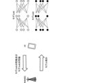
- FIG. 1 is a diagram illustrating an example of a framework for managing AI models.
- FIG. 2 is a diagram showing an example of specifying an AI model.
- FIG. 3 is a diagram illustrating an example of a UE positioning method.
- FIG. 4 is a diagram illustrating an example of a UE positioning method.
- FIG. 5 is a diagram illustrating an example of a UE positioning method.
- FIG. 6 is a diagram illustrating an example of a UE positioning method.
- FIG. 7 is a diagram illustrating an example of the start time/end time of latency according to the first embodiment.
- FIG. 8 is a diagram illustrating an example of a schematic configuration of a wireless communication system according to an embodiment.
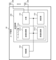
- FIG. 9 is a diagram illustrating an example of the configuration of a base station according to an embodiment.
- FIG. 10 is a diagram illustrating an example of the configuration of a user terminal according to an embodiment.
- FIG. 11 is a diagram illustrating an example of the hardware configuration of a base station and a user terminal according to an embodiment.
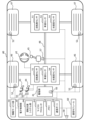
- FIG. 12 is a diagram illustrating an example of a vehicle according to an embodiment.
- AI Artificial Intelligence
- ML machine learning
- CSI channel state information
- UE user equipment
- BS base stations
- CSI channel state information
- UE user equipment
- beam management e.g., improving accuracy, prediction in the time/space domain
- position measurement e.g., improving position estimation/prediction
- the AI model may output at least one piece of information such as an estimate, a prediction, a selected action, a classification, etc. based on the input information.
- the UE/BS may input channel state information, reference signal measurements, etc. to the AI model, and output highly accurate channel state information/measurements/beam selection/position, future channel state information/radio link quality, etc.
- AI may be interpreted as an object (also called a target, object, data, function, program, etc.) having (implementing) at least one of the following characteristics: - Estimation based on observed or collected information; - making choices based on observed or collected information; - Predictions based on observed or collected information.
- estimation, prediction, and inference may be interpreted as interchangeable. Also, in this disclosure, estimate, predict, and infer may be interpreted as interchangeable.
- an object may be, for example, an apparatus such as a UE or a BS, or a device. Also, in the present disclosure, an object may correspond to a program/model/entity that operates in the apparatus.
- an AI model may be interpreted as an object having (implementing) at least one of the following characteristics: - Producing estimates by feeding information, - Predicting estimates by providing information - Discover features by providing information, - Select an action by providing information.
- an AI model may refer to a data-driven algorithm that applies AI techniques to generate a set of outputs based on a set of inputs.
- AI model, model, ML model, predictive analytics, predictive analysis model, tool, autoencoder, encoder, decoder, neural network model, AI algorithm, scheme, etc. may be interchangeable.
- AI model may be derived using at least one of regression analysis (e.g., linear regression analysis, multiple regression analysis, logistic regression analysis), support vector machine, random forest, neural network, deep learning, etc.
- autoencoder may be interchangeably referred to as any autoencoder, such as a stacked autoencoder or a convolutional autoencoder.
- the encoder/decoder of this disclosure may employ models such as Residual Network (ResNet), DenseNet, and RefineNet.
- encoder encoding, encoding/encoded, modification/alteration/control by an encoder, compressing, compress/compressed, generating, generate/generated, etc. may be read as interchangeable terms.
- decoder decoding, decode/decoded, modification/alteration/control by a decoder, decompressing, decompress/decompressed, reconstructing, reconstruct/reconstructed, etc.
- decompressing decompress/decompressed, reconstructing, reconstruct/reconstructed, etc.
- a layer for an AI model
- a layer may be interpreted as a layer (input layer, intermediate layer, etc.) used in an AI model.
- a layer in the present disclosure may correspond to at least one of an input layer, intermediate layer, output layer, batch normalization layer, convolution layer, activation layer, dense layer, normalization layer, pooling layer, attention layer, dropout layer, fully connected layer, etc.
- methods for training an AI model may include supervised learning, unsupervised learning, reinforcement learning, federated learning, and the like.
- Supervised learning may refer to the process of training a model from inputs and corresponding labels.
- Unsupervised learning may refer to the process of training a model without labeled data.
- Reinforcement learning may refer to the process of training a model from inputs (i.e., states) and feedback signals (i.e., rewards) resulting from the model's outputs (i.e., actions) in the environment with which the model interacts.
- terms such as generate, calculate, derive, etc. may be interchangeable.
- terms such as implement, operate, operate, execute, etc. may be interchangeable.
- terms such as train, learn, update, retrain, etc. may be interchangeable.
- terms such as infer, after-training, live use, actual use, etc. may be interchangeable.
- terms such as signal and signal/channel may be interchangeable.
- FIG. 1 shows an example of a framework for managing an AI model.
- each stage related to the AI model is shown as a block.
- This example is also referred to as Life Cycle Management (LCM) of the AI model.
- LCM Life Cycle Management
- the data collection stage corresponds to the stage of collecting data for generating/updating an AI model.
- the data collection stage may include data organization (e.g., determining which data to transfer for model training/model inference), data transfer (e.g., transferring data to an entity (e.g., UE, gNB) that performs model training/model inference), etc.
- data collection may refer to a process in which data is collected by a network node, management entity, or UE for the purpose of AI model training/data analysis/inference.
- process and procedure may be interpreted as interchangeable.
- model training is performed based on the data (training data) transferred from the collection stage.
- This stage may include data preparation (e.g., performing data preprocessing, cleaning, formatting, conversion, etc.), model training/validation, model testing (e.g., checking whether the trained model meets performance thresholds), model exchange (e.g., transferring the model for distributed learning), model deployment/update (deploying/updating the model to the entities that will perform model inference), etc.
- AI model training may refer to a process for training an AI model in a data-driven manner and obtaining a trained AI model for inference.
- AI model validation may refer to a sub-process of training to evaluate the quality of an AI model using a dataset different from the dataset used to train the model. This sub-process helps select model parameters that generalize beyond the dataset used to train the model.
- AI model testing may refer to a sub-process of training to evaluate the performance of the final AI model using a dataset different from the dataset used for model training/validation. Note that testing, unlike validation, does not necessarily require subsequent model tuning.
- model inference is performed based on the data (inference data) transferred from the collection stage.
- This stage may include data preparation (e.g., performing data preprocessing, cleaning, formatting, transformation, etc.), model inference, model monitoring (e.g., monitoring the performance of model inference), model performance feedback (feeding back model performance to the entity performing the model training), and output (providing model output to the actor).
- AI model inference may refer to the process of using a trained AI model to produce a set of outputs from a set of inputs.
- a UE side model may refer to an AI model whose inference is performed entirely in the UE.
- a network side model may refer to an AI model whose inference is performed entirely in the network (e.g., gNB).
- a one-sided model may refer to a UE-side model or a network-side model.
- a two-sided model may refer to a pair of AI models where joint inference is performed.
- joint inference may include AI inference where the inference is performed jointly across the UE and the network, e.g., a first part of the inference may be performed first by the UE and the remaining part by the gNB (or vice versa).
- AI model monitoring may refer to the process of monitoring the inference performance of an AI model, and may be interchangeably read as model performance monitoring, performance monitoring, etc.
- model registration may refer to making a model executable through assigning a version identifier to the model and compiling it into the specific hardware used in the inference phase.
- Model deployment may refer to distributing (or activating at) a fully developed and tested run-time image (or image of the execution environment) of the model to the target (e.g., UE/gNB) where inference will be performed.
- Actor stages may include action triggers (e.g., deciding whether to trigger an action on another entity), feedback (e.g., feeding back information needed for training data/inference data/performance feedback), etc.
- action triggers e.g., deciding whether to trigger an action on another entity
- feedback e.g., feeding back information needed for training data/inference data/performance feedback
- training of a model for mobility optimization may be performed in, for example, Operation, Administration and Maintenance (Management) (OAM) in a network (NW)/gNodeB (gNB).
- OAM Operation, Administration and Maintenance
- NW network
- gNodeB gNodeB
- In the former case interoperability, large capacity storage, operator manageability, and model flexibility (feature engineering, etc.) are advantageous.
- the latency of model updates and the absence of data exchange for model deployment are advantageous.
- Inference of the above model may be performed in, for example, a gNB.
- the entity performing the training/inference may be different.
- the function of the AI model may include beam management, beam prediction, autoencoder (or information compression), CSI feedback, positioning, etc.
- the OAM/gNB may perform model training and the gNB may perform model inference.
- a Location Management Function may perform model training and the LMF may perform model inference.
- the OAM/gNB/UE may perform model training and the gNB/UE may (jointly) perform model inference.
- the OAM/gNB/UE may perform model training and the UE may perform model inference.
- model activation may mean activating an AI model for a particular function.
- Model deactivation may mean disabling an AI model for a particular function.
- Model switching may mean deactivating a currently active AI model for a particular function and activating a different AI model.
- Model transfer may also refer to distributing an AI model over the air interface. This may include distributing either or both of the parameters of the model structure already known at the receiving end, or a new model with the parameters. This may also include a complete model or a partial model.
- Model download may refer to model transfer from the network to the UE.
- Model upload may refer to model transfer from the UE to the network.
- Figure 2 shows an example of specifying an AI model.
- the UE and NW e.g., a base station (BS)
- NW e.g., a base station (BS)
- the UE may report, for example, the capabilities of model #1 and model #2 to the NW, and the NW may instruct the UE on the AI model to use.
- Fingerprinting localization which estimates the location of a wireless device by utilizing the propagation characteristics of a wireless signal, is widely used in both Line Of Site (LOS) and Non-Line Of Site (NLOS) scenarios.
- LOS Line Of Site
- NLOS Non-Line Of Site
- LOS may mean that the UE and base station are in an environment where they can see each other (or there is no obstruction)
- NLOS may mean that the UE and base station are not in an environment where they can see each other (or there is obstruction).
- the multipath information may be, for example, information regarding the Angle of Arrival (AoA)/Angle of Departure (AoD) of the signal on optimal/candidate transmission paths.
- AoA Angle of Arrival
- AoD Angle of Departure
- the information on AoA may include, for example, information on at least one of the azimuth angles of arrival and the zenith angles of arrival.
- the information on AoD may include, for example, information on at least one of the azimuth angles of departure and the zenith angles of departure.
- 3GPP Rel. 16 NR supports the following positioning technologies: DL/UL Time Difference Of Arrival (TDOA) based positioning; Positioning based on angles (DL AoD/UL AoA); - Positioning based on multiple Round Trip Times (RTTs), - Positioning based on Enhanced Cell ID (E-CID).
- TDOA Time Difference Of Arrival
- RTT Round Trip Times
- E-CID Enhanced Cell ID
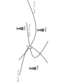
- FIG. 3 is a diagram showing an example of positioning based on DL/UL TDOA.
- TRP#0-#2 multiple base stations
- the location of the UE is estimated (measured) using a measurement value of the reception time difference (Reference Signal Time Difference (RSTD)) of the reference signal.
- RSTD Reference Signal Time Difference
- a hyperbola H i,j can be drawn by connecting points where the RSTD (T i -T j ) for two specific base stations (TRP#i, #j (i, j are integers)) takes a certain value (k i,j ) .
- the intersection of multiple such hyperbolae (in this example, the intersection of H 0,1, H 1,2, and H 2,0 ) may be estimated as the location of the UE.
- the location of the UE may be estimated using the RSRP of the reference signal.
- Figure 4 shows an example of positioning based on DL AoD/UL AoA.
- the UE's location is estimated using a DL AoD measurement value (e.g., ⁇ or ⁇ ) or a UL AoA measurement value (e.g., ⁇ or ⁇ ).
- the UE's location may also be estimated using RSRP.
- Figure 5 shows an example of multi-RTT based positioning.
- the UE's location is estimated using multiple RTTs calculated from the Tx/Rx time difference of the reference signal (and additionally RSRP, RSRQ, etc.). For example, geometric circles based on the RTTs can be drawn with each base station at the center. The intersection of these multiple circles may be estimated as the UE's location.
- Figure 6 shows an example of E-CID based positioning.
- the UE's location is estimated based on the geometrical location of the serving cell/neighbor cells and additional measurements (Tx-Rx time difference, RSRP, RSRQ, etc.).
- the positioning in the DL (DL TDOA, DL AoD) described above may be performed by the UE side or the LMF side.
- the UE may calculate the UE position based on various measurement results of the UE and assistance information from the LMF.
- the UE may report various measurement results to the LMF, and the LMF may calculate the UE position.
- the assistance information may be information for assisting in estimating the UE position.
- the above-mentioned UL (UL TDOA, UL AoA) positioning may be performed by the LMF.
- the base station may report various measurement results to the LMF, and the LMF may calculate the UE's position.
- the above-mentioned positioning in DL and UL may be performed by the LMF.
- the UE/base station may report various measurement results to the LMF, and the LMF may calculate the UE's position.
- 3GPP Rel. 17 proposes a positioning method using assistance information to further improve positioning accuracy.
- Assistance information may be transmitted between the UE, base station, and LMF as measurement information for the above-mentioned DL/UL-TDOA, DL-AoD/UL-AoA, multi-RTT, and E-CID.
- the assistance information may include information regarding at least one of the following: Timing Error Group (TEG), RSRPP (path-specific RSRP), Expected angle, Adjacent beam information, ⁇ TRP antenna/beam information, - LOS/NLOS indicator, ⁇ Additional path reporting.
- TAG Timing Error Group
- RSRPP path-specific RSRP
- Expected angle Adjacent beam information
- ⁇ TRP antenna/beam information - LOS/NLOS indicator
- ⁇ Additional path reporting may include information regarding at least one of the following: Timing Error Group (TEG), RSRPP (path-specific RSRP), Expected angle, Adjacent beam information, ⁇ TRP antenna/beam information, - LOS/NLOS indicator, ⁇ Additional path reporting.
- the TEG may indicate one or more Positioning Reference Signal (PRS) resources within which the Rx/Tx timing errors are within a certain margin.
- PRS Positioning Reference Signal
- RSRPP may indicate the RSRP measurement result on the first pass.
- assistance information regarding expected angles may indicate expected UL-AoA/ZoA.
- the assistance information may be transmitted from the LMF to the base station.
- the assistance information may also support at least one of UL TDOA, UL AoA, and multi-RTT positioning.
- the assistance information regarding expected angles may include information regarding expected DL-AoA/ZoA or DL-AoD/ZoD.
- the assistance information may be transmitted from the LMF to the UE.
- the assistance information may also support at least one of DL TDOA, DL AoA, and multi-RTT positioning. This improves the accuracy of angle-based UE positioning and enables optimization of Rx beamforming of the UE or base station.
- the assistance information regarding the predicted angles may include, in addition to the information on the values of AoA/ZoA/AoD/ZoD themselves as described above, information indicating the uncertainty range of these values.
- the neighboring beam information may include information on a subset of DL-PRS resources (option 1) for the purpose of prioritizing DL-AoD reports, or on the boresight direction of each DL-PRS resource (option 2), allowing optimization of the UE's Rx beam sweeping and DL-AoD measurements.
- the assistance information may also include PRS beam pattern information.
- This PRS beam pattern information may include information regarding the relative power between DL-PRS resources for each angle for each TRP.
- the LOS/NLOS indicator may show information regarding Line Of Site (LOS)/Non-Line Of Site (NLOS).
- pre-configured measurement gaps MG
- activation of the MG via lower layers MG-less position
- PRS Rx/Tx in RRC_INACTIVE state PRS Rx/Tx in RRC_INACTIVE state
- on-demand PRS may be configured for the UE (or may be used by the UE).
- the UE measures/reports the RSRP of adjacent beams to improve the accuracy of the UE's location estimation.
- the LMF can indicate at least one of the following options 1-2 in the assistance information.
- Option 1 A subset of PRS resources for DL-AOD reporting prioritization.
- the subset may be configured for each PRS resource depending on the UE capabilities.
- the UE may include requested PRS measurements for a subset of PRS in the DL-AoD additional measurements if requested PRS measurements for the associated PRS are reported.
- the requested PRS measurements may be DL PRS RSRP/path PRS RSRP.
- the UE may report PRS measurements only for a subset of PRS resources. Note that the associated subset of a PRS resource may be in the same/different PRS resource set as the PRS resource.
- Option 2 Information about the boresight direction configured for each PRS resource depending on the UE capabilities.
- PRU Positioning Reference Unit
- the PRU is being discussed as a reference device with a known location to mitigate transmission and reception timing errors of the UE/gNB.
- PRU may also be read as UE/gNB/TRP (transmission reception point)/TP (transmission point).
- a PRU may support at least one of the following: Measure DL PRS and report related measurements (e.g. RSTD/transmission time difference/RSRP) to the LMF; Transmitting SRS and enabling the TRP to measure and report measurements related to the reference device (e.g., Relative Time of Arrival (RTOA)/AOA) to the LMF; Operation, measurement and various parameters (parameters related to transmit/receive timing delays, AoD and AOA enhancements, and calibration of measurements); If the LMF does not have the position coordinate information, reporting the position coordinate information of the reference device to the LMF;
- the reference device with a known location is a UE/gNB; - The accuracy with which the position of the reference device can be known.
- Direct AI/ML positioning for example, outputs UE positioning.
- AI/ML assisted positioning for example, outputs intermediate features. These intermediate features may be input again into the AI/ML model.
- Example outputs of the AI/ML assisted positioning described above may include at least one of the following: LOS/NLOS identification (LOS/NLOS probability); ToA (time of arrival of PRS/SRS), - Rx-Tx (transmission and reception) time difference, ⁇ AoA/AoD, Number of waves, Rx-Tx (transmit/receive) phase difference (Rel. 18 phase measurement), DL RSTD/UL TDOA, DL-PRS/UL-SRS, RSRPs/RSRPPs, - Likelihood of the above numbers (e.g., probability of ToA).
- LOS/NLOS identification LOS/NLOS probability
- ToA time of arrival of PRS/SRS
- - Rx-Tx transmission and reception time difference
- ⁇ AoA/AoD Number of waves
- Rx-Tx transmit/receive phase difference
- DL RSTD/UL TDOA DL-PRS/UL-SRS
- Beam information for UE positioning As mentioned above, antenna configuration/beam information is considered useful for the AI/M1 model.
- the AI model requires metadata (antenna configuration information/beam information) as input to provide better performance.
- - Beam information is also used in interfaces other than positioning protocols (e.g., LTE Positioning Protocol (LPP)).
- LTP LTE Positioning Protocol
- PRS Positioning Reference Signal
- - Beam information at the UE is used.
- beam information indicating the direction of the beam (boresight direction) for each PRS is supported as beam information from the LMF to the UE (beam information for UE-based positioning, information on the transmission beam of the base station).
- the beam information may be information indicating the boresight direction for each PRS.
- the beam information indicating the beam direction for each PRS is "DL-PRS-BeamInfoElement" included in the common NR positioning information element "NR-DL-PRS-BeamInfo”.
- DL-PRS-BeamInfoElement includes information about the azimuth angle and elevation angle of the beam transmitted from the base station (TRP).
- dl-PRS-Azimuth Information regarding the azimuth angle is "dl-PRS-Azimuth” and “dl-PRS-Azimuth-fine”.
- dl-PRS-Azimuth is information expressed in units of 1 degree, with values ranging from 0° to 359°
- dl-PRS-Azimuth-fine is information expressed in units of 0.1 degree, with values ranging from 0° to 0.9°.
- dl-PRS-Elevation is information that is expressed in 1° units and values from 0° to 180°
- dl-PRS-Elevation-fine is information that is expressed in 0.1° units and values from 0° to 0.9°.
- Rel. 17 supports beam information indicating the relative power of DL PRS at each angle (azimuth angle/elevation angle) as beam information from the LMF to the UE (beam information for UE-based positioning, information on the base station's transmission beam).
- the beam information indicating the relative power is included in the beam antenna information of the TRP in the common NR positioning information element ("NR-TRP-BeamAntennaInfo").
- NR-TRP-BeamAntennaInfo includes information about the TRP's beam antenna information for azimuth and elevation angles, "NR-TRP-BeamAntennaInfoAzimuthElevation”.
- NR-TRP-BeamAntennaInfoAzimuthElevation includes “azimuth”, which indicates the azimuth angle in 1° increments, “azimuth-fine”, which indicates the azimuth angle in 0.1° increments, and “elevationList”, a list of elevation angles.
- the elevation list “elevationList” includes “elevation”, which indicates the elevation angle in 1° granularity, “elevation-fine”, which indicates the elevation angle in 0.1° granularity, and “beamPowerList”, which is a list of beam powers.
- the beam power list "beamPowerList” includes "nr-dl-prs-ResourceSetID” indicating the resource set ID of the DL PRS, "nr-dl-prs-ResourceID” indicating the resource ID of the DL PRS, "nr-dl-prs-RelativePower” indicating the relative power of the resource given by “nr-dl-prs-ResourceID” in 1 dB granularity, and "nr-dl-prs-RelativePowerFine” indicating the relative power of the resource given by "nr-dl-prs-ResourceID” in 0.1 dB granularity.
- Rel. 17 supports information indicating antenna reference points (ARPs) as beam (antenna) information (information about the base station's transmission beam) from the LMF to the UE.
- ARPs antenna reference points
- antenna reference points as beam (antenna) information (information about the base station's transmission beam)
- This information is indicated by the "referencePoint” in "NR-TRP-LocationInfo", which is the location information of the TRP in the common NR positioning information element.
- the TRP location information "NR-TRP-LocationInfo" is expressed by the relative positions between reference points.
- the ARP location of a PRS resource is expressed as a relative location associated with the ARP location of the PRS resource set.
- Antenna reference points are indicated by altitude, latitude and longitude.
- Rel. 17 supports information on the spatial direction of DL PRS as information from base stations (e.g., gNBs, NG-RAN (Next Generation-Radio Access Network) nodes) to the LMF (information on the base station's transmission beam).
- base stations e.g., gNBs, NG-RAN (Next Generation-Radio Access Network) nodes
- LMF Next Generation-Radio Access Network
- This information includes information indicating the boresight directions of the azimuth and elevation angles of the PRS resource.
- the information also includes transition information from the local coordinate system (LCS) to the global coordinate system (GCS).
- LCS local coordinate system
- GCS global coordinate system
- the GCS may be defined for a system including multiple base stations and multiple UEs.
- an array antenna for one base station or one UE may be defined.
- the LCS is used as a reference to define the vector far-field of each antenna element in the array, which is the pattern and polarization.
- the arrangement of the array within the GCS may be defined by a transformation between the GCS and the LCS.
- the GCS/LCS may be derived, for example, based on definitions and transformation formulas (specified in the specification) that would be recognizable to a person skilled in the art.
- Rel. 17 supports information indicating the beam/antenna of the TRP as information from the base station (e.g., gNB) to the LMF (information regarding the base station's transmission beam).
- the base station e.g., gNB
- the LMF information regarding the base station's transmission beam
- This information includes information showing the relative power of the DL PRS at each angle (azimuth/elevation).
- Rel. 17 supports information about the receiving beam when measuring UL signals as information from a base station (e.g., a gNB) to the LMF (information about the base station's receiving beam).
- a base station e.g., a gNB
- LMF information about the base station's receiving beam
- the information includes at least one of the PRS resource ID, the PRS resource set ID, and the SSB index.
- Rel. 17 supports information about spatial relationships as information transmitted from the UE to the NW (information about the UE's transmission beam).
- the information indicates the ID/index of a specific RS (e.g., SSB/CSI-RS/SRS/DL PRS).
- a specific RS e.g., SSB/CSI-RS/SRS/DL PRS.
- Rel. 17 specifies the number of receiving beams for a UE in beam sweeping for positioning.
- a UE may report support for UE capabilities to the LMF.
- the UE uses one receiving beam.
- the number of beams is used as indicated by the information "numberOfRxBeamSweepingFactor" indicating the number of Rx beam sweeping factors for FR2. Otherwise, the UE uses eight receiving beams.
- nr-DL-PRS-RxBeamIndex Information regarding the receiving beam that the UE uses for measurements.
- the UE may report measurements received on the same receiving beam.
- the beam information transmitted by the UE indicates whether the same beam is being used between resource sets.
- AI model information may mean information including at least one of the following: - AI model input/output information, - Pre-processing/post-processing information for input/output of AI models; ⁇ Information on the parameters of the AI model, - Training information for the AI model; - Inference information for AI models, ⁇ Performance information about the AI model.
- the input/output information of the AI model may include information regarding at least one of the following: Content of input/output data (e.g. RSRP, SINR, amplitude/phase information in the channel matrix (or precoding matrix), information on the Angle of Arrival (AoA), information on the Angle of Departure (AoD), location information); - auxiliary information of the data (which may be called meta-information); - Input/output data types (e.g. immutable values, floating point numbers), Quantization interval (quantization step size) of input/output data (e.g., 1 dBm for L1-RSRP); The range that the input/output data can take (e.g., [0, 1]).
- Content of input/output data e.g. RSRP, SINR, amplitude/phase information in the channel matrix (or precoding matrix), information on the Angle of Arrival (AoA), information on the Angle of Departure (AoD), location information
- - auxiliary information of the data
- GC Generalization Capability
- AI/ML AI/ML
- GC refers to the ability of an AI model to adapt (produce desired output, make good predictions) not only to the training data given during training, but also to unknown data (test data).
- GC performance is also called GC performance (or generalization performance).
- KPI Key performance indicators
- KPIs for evaluating the performance impact of AI/ML models: ⁇ Performance ⁇ Intermediate KPIs, - Link-level and system-level performance, ⁇ Generalization performance, Over-the-air (overhead) - Assistance information overhead, - Data collection overhead, Model delivery/transfer overhead, - Signaling overhead associated with other AI/ML models; Inference complexity, Computational complexity of model inference: floating point operations (FLOPs (note that s is lowercase)) (this means the amount of floating point operations), - Computational complexity of pre- and post-processing, -Model complexity (number of parameters/data size (e.g.
- KPIs are merely examples and other KPIs may be added to the list (e.g. KPIs related to model training, use case specific KPIs that are considered for a given use case, etc.).
- the percentiles of positioning error may be 50%, 67%, 80%, and 90%.
- the horizontal accuracy may indicate the difference between the calculated horizontal position of the UE and the actual horizontal position of the UE, for example, the horizontal accuracy may be less than 0.2 meters for 90% of the UEs.
- the vertical accuracy may indicate the difference between the calculated UE vertical position and the actual UE vertical position, for example, the vertical accuracy may be less than 1 meter for 90% of the UEs.
- the latency may be, for example, the end-to-end latency for the UE location estimation.
- the latency may be less than 100 ms (more preferably in the order of 10 ms).
- the latency may include processing delays of the various nodes involved (UE, gNB, AMF, LMF, etc.) and signalling delays between the nodes.
- Other latencies may include the physical layer latency for the UE location estimation.
- the latency may be, for example, less than 10 ms.
- Positioning Classification Positioning using AI models may be categorized as follows: (1) UE-based positioning; (2) AI/ML assisted positioning, (3) NG-RAN (Next Generation-Radio Access Network) Node Assisted Positioning.
- (1) UE-based positioning can be further classified as follows: (1-1) Direct AI/ML positioning in UE side model, (1-2) AI/ML assisted positioning in UE side model and non-AI based positioning in UE side algorithm.
- AI/ML assisted positioning can be further classified as follows: (2-1) AI/ML assisted positioning in the UE side model and non-AI based positioning in the LMF side algorithm; (2-2) Direct AI/ML positioning in LMF side model.
- (3) NG-RAN node assisted positioning can be further classified as follows: (3-1) AI/ML assisted positioning in the gNB side model and non-AI based positioning in the LMF side algorithm; (3-2) Direct AI/ML positioning in LMF side model.
- model monitoring for direct AI/ML positioning with UE-side models may be performed by at least one of the following: ⁇ 1> Performance metrics calculation in the UE; ⁇ 2> Performance metrics calculation in LMF.
- model monitoring for AI/ML assisted positioning with UE-side models may be performed by at least one of the following: ⁇ 3> Performance metrics calculation in the UE; ⁇ 4> Performance metrics calculation in LMF.
- model monitoring for AI/ML assisted positioning with UE side models may be done by: ⁇ 5> Performance metrics calculation in LMF.
- model monitoring for AI/ML assisted positioning by a gNB side model may be performed by at least one of the following: ⁇ 6> Performance metrics calculation in gNB, ⁇ 7> Performance metrics calculation in LMF.
- Step 1 The UE obtains a noisy ground truth UE position.
- Step 1' The UE obtains an estimated UE position from model inference.
- Step 2 The UE calculates the performance metrics of the model monitoring.
- Step 3 The UE reports performance metrics of the model monitoring.
- Step 3' The UE requests model activation/deactivation/switching to the LMF.
- Step 4 The UE receives model activation/deactivation/switching indication from the LMF.
- Step 5 The UE performs model activation/deactivation/switching.
- the performance metrics calculation (model monitoring) described above in ⁇ 2> may be performed according to the following steps.
- Step 1 The UE obtains and reports the UE position from model inference.
- Step 1' The LMF obtains a noisy ground truth UE position (the true value for the UE location).
- Step 2 The LMF computes the performance metrics of the model monitoring.
- Step 3 The UE receives model activation/deactivation/switching indication from the LMF.
- Step 1 The UE acquires noisy ground truth data (the true value for some data (e.g. UE position)).
- Step 1' The UE obtains estimation data from model inference.
- Step 2 The UE calculates the performance metrics of the model monitoring.
- Step 3 The UE reports performance metrics of the model monitoring.
- Step 3' The UE requests model activation/deactivation/switching to the LMF.
- Step 4 The UE receives model activation/deactivation/switching indication from the LMF.
- Step 5 The UE performs model activation/deactivation/switching.
- the performance metrics calculation (model monitoring) of ⁇ 4> and ⁇ 5> described above may be performed according to the following steps.
- Step 1 The UE obtains and reports estimation data from model inference.
- Step 2 The LMF obtains ground truth data (the true value for a certain data (e.g. UE position)).
- Step 3 The LMF computes the performance metrics of the model monitoring.
- Step 4 The UE receives model activation/deactivation/switching indication from the LMF.
- Step 5 The UE performs model activation/deactivation/switching.
- Step 1 The gNB obtains and reports estimated data from model inference.
- Step 1' The gNB obtains ground truth data (the true value for certain data (e.g., UE position)).
- Step 2 The gNB calculates performance metrics for the model monitoring.
- Step 3 The gNB reports performance metrics of the model monitoring.
- Step 3' The gNB requests model activation/deactivation/switching from the LMF.
- Step 4 The gNB receives a model activation/deactivation/switching instruction from the LMF.
- Step 5 The gNB performs model activation/deactivation/switching.
- the performance metrics calculation (model monitoring) of ⁇ 7> above may be performed according to the following steps.
- Step 1 The gNB obtains and reports estimated data from model inference.
- Step 2 The LMF obtains ground truth data (the true value for a certain data (e.g. UE position)).
- Step 3 The LMF computes the performance metrics of the model monitoring.
- Step 4 The gNB receives a model activation/deactivation/switching instruction from the LMF.
- Step 5 The gNB performs model activation/deactivation/switching.
- AI model #1 the output (ToA, RSTD, RSRP, Rx-Tx time difference, etc., which may be intermediate values of positioning) of one AI model (AI model #1) can be applied as input to another AI model (AI model #2)
- the performance of AI model #2 may be affected by the accuracy of the output of AI model #1. If AI model #2 does not converge/cannot be trained well, or the test performance does not meet the requirements, how to handle the joint training model may be an issue.
- the angle at which a signal arrives at a UE, the AoA at the UE, and the AoA at the base station may be read as interchangeable.
- the angle at which a signal is emitted at a UE, the AoD at the UE, and the AoD at the base station may be read as interchangeable.
- the AoA and the AoD may be read as interchangeable.
- the UE and the base station may be read as interchangeable.
- a terminal (user terminal, User Equipment (UE))/base station (BS) trains an ML model in a training mode and implements the ML model in an inference mode (also called an inference mode, etc.).
- an inference mode also called an inference mode, etc.
- the accuracy of the trained ML model in the training mode may be verified.
- an object may be, for example, an apparatus or device such as a terminal or base station. Also, in this disclosure, an object may correspond to a program/model/entity that operates in the apparatus.
- A/B and “at least one of A and B” may be interpreted as interchangeable. Also, in this disclosure, “A/B/C” may mean “at least one of A, B, and C.”
- Radio Resource Control RRC
- RRC parameters RRC parameters
- RRC messages higher layer parameters, fields, information elements (IEs), settings, etc.
- IEs information elements
- CE Medium Access Control
- update commands activation/deactivation commands, etc.
- the higher layer signaling may be, for example, Radio Resource Control (RRC) signaling, Medium Access Control (MAC) signaling, broadcast information, positioning protocol (e.g., NR Positioning Protocol A (NRPPa)/LTE Positioning Protocol (LPP)) messages, or any combination thereof.
- RRC Radio Resource Control
- MAC Medium Access Control
- LPP LTE Positioning Protocol
- the MAC signaling may use, for example, a MAC Control Element (MAC CE), a MAC Protocol Data Unit (PDU), etc.
- the broadcast information may be, for example, a Master Information Block (MIB), a System Information Block (SIB), Remaining Minimum System Information (RMSI), Other System Information (OSI), etc.
- MIB Master Information Block
- SIB System Information Block
- RMSI Remaining Minimum System Information
- OSI System Information
- the physical layer signaling may be, for example, Downlink Control Information (DCI), Uplink Control Information (UCI), etc.
- DCI Downlink Control Information
- UCI Uplink Control Information
- index identifier
- indicator indicator
- resource ID etc.
- sequence list, set, group, cluster, subset, etc.
- TRP
- CSI-RS Non-Zero Power (NZP) CSI-RS, Zero Power (ZP) CSI-RS, and CSI Interference Measurement (CSI-IM) may be interchangeable.
- CSI-RS may include other reference signals.
- the measured/reported RS may refer to the RS measured/reported for CSI reporting.
- timing, time, duration, slot, subslot, symbol, subframe, etc. may be interpreted as interchangeable.
- direction, axis, dimension, domain, polarization, polarization component, etc. may be interpreted as interchangeable.
- estimation, prediction, and inference may be interpreted as interchangeable. Also, in this disclosure, estimate, predict, and infer may be interpreted as interchangeable.
- the autoencoder, encoder, decoder, etc. may be interpreted as at least one of a model, an ML model, a neural network model, an AI model, an AI algorithm, etc.
- the autoencoder may be interpreted as any autoencoder, such as a stacked autoencoder or a convolutional autoencoder.
- the encoder/decoder of the present disclosure may employ models such as Residual Network (ResNet), DenseNet, and RefineNet.
- bits, bit strings, bit series, series, values, information, values obtained from bits, information obtained from bits, etc. may be interpreted as interchangeable.
- a layer for an encoder
- a layer may be interchangeably read as a layer (input layer, intermediate layer, etc.) used in an AI model.
- a layer in the present disclosure may correspond to at least one of an input layer, intermediate layer, output layer, batch normalization layer, convolution layer, activation layer, dense layer, normalization layer, pooling layer, attention layer, dropout layer, fully connected layer, etc.
- RSRP may be interchangeably read as any parameter related to reception power/reception quality, etc. (e.g., RSRQ, SINR, CSI, etc.).
- positioning may be interchangeably read as position determination, position estimation, position prediction, etc.
- KPI Key Performance Indicator
- performance metrics may be interchangeably read as KPI (Key Performance Indicator)
- performance metrics calculation may be interchangeably read as KPI (Key Performance Indicator)
- KPI Key Performance Indicator
- the first embodiment relates to performance metrics for model monitoring.
- Performance metrics for model monitoring can include at least one of the following: ⁇ Performance Latency, ⁇ Complexity.
- Performance may include at least one of the following: - Horizontal accuracy of AI/ML based positioning (meters); Vertical accuracy of AI/ML based positioning (meters); - Accuracy of intermediate features for AI/ML-based positioning.
- Horizontal accuracy may indicate the difference between the calculated UE horizontal position and the actual UE horizontal position. For example, horizontal accuracy may be less than 0.2 m for 90% of the UEs.
- Vertical accuracy may indicate the difference between the calculated UE vertical position and the actual UE vertical position. For example, vertical accuracy may be less than 1 m for 90% of the UEs.
- the intermediate feature accuracy may indicate the difference between the inferred intermediate value and the intermediate value derived based on the actual UE location.
- the intermediate feature accuracy may be indicated by at least one of the following, for example: accuracy of LOS/NLOS indicator (error rate %), ToA (milliseconds), AoA (degrees), RSTD (milliseconds), RSRP (dBm), etc.
- Latency may include at least one of the following: - Physical layer latency (ms), - End-to-end latency (ms).
- the latency in the positioning procedure may be defined, for example, according to the diagram shown in FIG. 7.
- FIG. 7 is a diagram showing an example of the start time/end time of the latency of the physical layer according to the first embodiment. As shown in FIG. 7, the latency of the physical layer may be defined individually depending on the positioning method.
- the start time may be the timing when the UE transmits a PUSCH including an MG request (Alt1), the timing when the gNB transmits an LPP message including assistance data using the PDSCH (Alt2), or the timing when the UE starts receiving DL PRS (Alt3).
- the end time in this case may be the timing when the gNB successfully decodes a PUSCH including an LPP Provide Location Information message, or when the UE performs a location estimation calculation if not successful.
- the start time may be the timing when the gNB transmits a PDSCH including an LPP Request Location Information message.
- the end time in this case may be the timing when the gNB successfully decodes a PUSCH including an LPP Provide Location Information message.
- the start time may be the timing when the gNB receives the NRPPa measurement request message.
- the end time may be the timing when the gNB transmits the NRPPa measurement response message.
- the latency of the AI model is not limited to the example in FIG. 7.
- the start time may be the timing when the UE/NW receives the input of the model inference
- the end time may be the timing when the NW/UE receives the output of the AI model.
- the end-to-end latency may be the latency for UE location estimation.
- the latency may include higher layer latency as another latency.
- the latency may include processing delays of the various nodes involved (UE, gNB, AMF, LMF, etc.) and signaling delays between the nodes.
- the definition of each of the above latencies may follow the definition in Rel. 17.
- Complexity may be defined as the computational complexity of model inference (floating point operations (FLOPs)).
- the complexity of an AI model may also be defined, for example, by the data size (Mbytes) of the model and the number of parameters associated with the AI model.
- Embodiment 1.1 relates to a method for indicating (notifying) performance metrics.
- Performance metrics may be indicated to the UE/gNB that deploys the AI model.
- the NW may notify performance metrics via signaling such as LPP/MAC CE/DCI/RRC/NRPPa.
- the UE/NW may report performance metrics based on predefined rules.
- the entire LCM in AI-based positioning may include signal exchange via LPP between the UE and the LMF, and signal exchange via NRPPa between the gNB and the LMF.
- Embodiment 1.2 relates to the accuracy of performance metrics, etc.
- ⁇ Option 1.2.1.1> The geodesic distance difference between the one-shot inferenced value related to the horizontal/vertical position and the actual horizontal/vertical position at the UE/PRU.
- ⁇ Option 1.2.1.2> The average value of the difference in geodesic distance between the inferred values related to the horizontal/vertical position and the actual horizontal/vertical position of the UE/PRU within a certain time duration.
- the certain duration may be determined based on at least one of the following rules: - by predefined rules,
- the NW instructing the UE / gNB via signaling such as LPP / MAC CE / DCI / RRC / NRPPa, Depends on the implementation of the NW/UE (for example, continuing monitoring for a certain time unit).
- the UE may report its actual horizontal/vertical position to the NW via signaling such as LPP/MAC CE/DCI/RRC/NRPPa.
- the actual horizontal/vertical position of the PRU is recognized by the NW, and the NW/PRU can indicate the horizontal/vertical position to the UE/gNB via signaling such as LPP/MAC CE/DCI/RRC/NRPPa.
- the UE preferably has Global Navigation Satellite System (GNSS) capability.
- GNSS Global Navigation Satellite System
- the UE/PRU mentioned above may be defined as a monitoring device that is always involved in the inference/monitoring of the AI model and can always provide actual location information.
- the time difference (in milliseconds) of the inference information compared to the ground truth data may be a one-shot or an average value over a period of time (certain time duration as mentioned above).
- the ground truth data may be obtained from the actual location of the UE. This allows the actual location of the UE to be reused. This option may be applied when the intermediate value is ToA, RSTD, Rx-Tx time difference, etc.
- the ground truth data may be the true value of the value to be estimated or predicted, a value close to the true value, or a highly reliable predicted value.
- the data treated as ground truth data is expected to have an error from the true value, it may be called noisy ground truth data.
- the intermediate value described above is not limited to an actual measurement value and may be a likelihood (such as a probability distribution of ToA/AoA/RSRP).
- the output of the AI model may be a probability distribution of ToA where X% satisfies N milliseconds. In this case, it can be defined that X% satisfies N milliseconds as an output requirement.
- the performance metric is defined by probability, no operation may be required if X ⁇ X0.
- the performance metric is defined by a probability difference, no operation may be required if X0 ⁇ X ⁇ threshold.
- the reliability of these estimated accuracy may also be calculated/estimated.
- the UE may have GNSS capabilities and the ability to derive intermediate values based on the position available from the GNSS.
- Embodiment 1.3 relates to the performance metric Performance.
- the ability to apply a performance metric may be expressed in terms of at least one of the following: Performance of a single measured value (which may be an output value at a certain point in time (one-shot) or an average value over a certain period of time) applicable to model monitoring on the UE/NW side; Cumulative Distribution Function (CDF) percentage performance corresponding to multiple values applicable to model monitoring at UE/NW side.
- Performance of a single measured value which may be an output value at a certain point in time (one-shot) or an average value over a certain period of time
- CDF Cumulative Distribution Function
- the above mentioned value may be at least one of the following: - Output values of multiple AI models (corresponding to the same or different UEs) at a certain point in time (one-shot), or the average value of the output value of one AI model within a time period associated with multiple AI models; - Multiple values corresponding to the output of an AI model at a given time.
- the value may also be X% of the value monitored over a period of time, where the period of time and X may be determined based on at least one of the following: - by predefined rules,
- the NW instructing the UE / gNB via signaling such as LPP / MAC CE / DCI / RRC / NRPPa, Depends on the implementation of the NW/UE (for example, continuing monitoring for a certain time unit).
- the performance metric requirements may be predefined or may be set by the network. For example, the positioning requirements of Rel. 17 may be reused and various requirements may be determined based on the results of AI-based positioning. In this disclosure, the performance metric requirements may be interpreted as requirements regarding the applicability of performance metrics, model monitoring requirements, etc.
- performance metrics can be appropriately defined/indicated.
- the second embodiment relates to the application of model monitoring/performance metrics.
- monitoring information and output information of an AI model may be interchangeable.
- Embodiment 2.1 relates to the application of performance metrics on the UE side.
- the UE may determine whether the performance metrics requirements are met.
- the UE may report at least one of the following monitoring information to the NW via signaling such as LPP/MAC CE/DCI/RRC/NRPPa: - The accuracy of the output information of the monitored AI model, The difference between the inferred and actual horizontal/vertical positions, Difference between the inferred outputs (ToA, AoA, RSTD, RSRP, etc.) and those obtained from the actual location (ToA, AoA, RSTD, RSRP, etc.); -Latency difference, - Complexity of AI models and latency, required complexity) A binary indicator of whether a performance metric requirement is met; - Calculated estimated accuracy (horizontal accuracy/vertical accuracy/intermediate feature accuracy), - Information regarding the reliability (value) of the estimation accuracy.
- signaling such as LPP/MAC CE/DCI/RRC/NRPPa
- the above-mentioned monitoring information may be reported based on at least one of the following options: ⁇ Option 1> - When some of a set of conditions are met (for example, performance metrics do not meet certain requirements), ⁇ Option 2> ⁇ After monitoring, always report (report unconditionally), ⁇ Option 3> Report based on configuration/NW instructions (e.g., periodic, semi-permanent, non-periodic).
- Embodiment 2.2 relates to the application of performance metrics on the gNB side.
- the gNB may determine whether the performance metrics requirements are met.
- the UE/LMF may report at least one of the following AI model output information to the gNB/LMF via signaling such as LPP/MAC CE/DCI/RRC/NRPPa.
- the UE may report to the gNB via the LMF: Inferred UE coordinates, Inferred ToA, Inferred LOS/NLOS indicators; Inferred AoA, RSTD, RSRP, - The complexity of AI models, ⁇ Latency.
- the gNB may instruct the UE/LMF of at least one of the above-mentioned monitoring information (UE-side information) via signaling such as LPP/MAC CE/DCI/RRC/NRPPa.
- Embodiment 2.3 relates to the application of performance metrics on the LMF side.
- the LMF may determine whether the performance metrics requirements are met.
- the UE/gNB may report at least one of the following AI model output information to the NW via signaling such as LPP/MAC CE/DCI/RRC/NRPPa: Inferred UE coordinates, Inferred ToA, Inferred LOS/NLOS indicators; Inferred AoA, RSTD, RSRP, - The complexity of AI models, ⁇ Latency.
- the LMF may instruct the UE/gNB of at least one of the above-mentioned monitoring information (UE-side information) via signaling such as LPP/MAC CE/DCI/RRC/NRPPa.
- model monitoring and model inference are performed by the same entity (UE/gNB/LMF).
- model monitoring can be performed appropriately.
- the third embodiment relates to actions after model monitoring.
- the UE may take at least one of the following options after model monitoring: ⁇ Option 1> The UE may perform model switching/update (fine-tuning, re-training)/fallback. If the UE performs these operations, it may report the operations to the gNB/LMF. ⁇ Option 2> The UE may send a request regarding upcoming operations to the gNB/LMF.
- the gNB may take at least one of the following options after model monitoring: ⁇ Option 1> The gNB can perform model switching/update (fine-tuning, re-training)/fallback. ⁇ Option 2> -The gNB may instruct the UE / LMF of expected operations.
- Embodiment 3.1 a method for a UE to determine whether to perform the operation (specific operation) shown in embodiment 3.0 will be described. In embodiments 3.1.1 to 3.1.3, variations of the method for determining the operation will be described.
- the UE may determine whether or not to perform a specific operation after monitoring based on information from the NW.
- the NW may indicate the above-mentioned monitoring information to the UE via signaling such as LPP/MAC CE/DCI/RRC/NRPPa.
- the monitoring information may include a monitoring information threshold for performing a certain specific operation. That is, the UE may determine a specific operation based on these monitoring information.
- the UE may report to the NW that it will perform/has performed the specific operation via signaling such as LPP/MAC CE/DCI/RRC/NRPPa.
- the UE may know whether or how to perform a specific action after monitoring and may send a request to the gNB/NW.
- the NW may indicate the monitoring information to the UE, similar to [Embodiment 3.1.1].
- the UE may send a request to the NW via signaling such as LPP/MAC CE/DCI/RRC/NRPPa, including the following information: A one-bit indicator to request model switch/update/fallback action; For AI models with outputs such as direct AI positioning and AI assisted positioning, the required functionality of the AI model to be switched; - The monitored AI model ID that cannot meet the performance metrics requirements; - AI model ID requesting switching, - Unqualified parameters in the AI model that need to be updated; - Datasets used to train/update (fine-tune) AI models; Timing information (e.g. timestamps) for applying a fallback scheme (a fallback scheme may be a configured positioning method); Desired/required PRS configuration, desired/required model inputs (e.g., number of PRS ports, multipath information).
- signaling such as LPP/MAC CE/DCI/RRC/NRPPa, including the following information: A one-bit indicator to request model switch/update/fallback action; For AI models
- the UE may determine the post-monitoring action after receiving an instruction from the NW.
- the UE may send a report to the NW via signaling such as LPP/MAC CE/DCI/RRC/NRPPa, including the following information: Among the monitored AI models, the monitored AI model ID that needs to be updated; ⁇ Switchable AI model ID, - Unqualified parameters in the AI model that need to be updated; - Datasets used to train/update (fine-tune) AI models; Timing information (e.g. timestamps) for applying a fallback scheme (a fallback scheme may be a configured positioning method); Input information for the updated AI model (number of PRS ports, multipath information, etc.), Desired/required PRS configuration, desired/required model inputs (e.g., number of PRS ports, multipath information).
- signaling such as LPP/MAC CE/DCI/RRC/NRPPa, including the following information: Among the monitored AI models, the monitored AI model ID that needs to be updated; ⁇ Switchable AI model ID, - Unqualified parameters in the AI model
- Embodiment 3.2 In embodiment 3.2, how the NW (gNB / LMF) determines the execution of the operation (specific operation) shown in the above-mentioned embodiment 3.0 will be described. In embodiments 3.2.1 to 3.2.3, variations of the method of determining the operation will be described.
- the NW may determine whether or not to execute a specific operation after monitoring.
- the UE/gNB may report the above-mentioned monitoring information to the NW via signaling such as LPP/MAC CE/DCI/RRC/NRPPa.
- the NW may recognize and instruct the UE whether to perform a specific operation after monitoring.
- the UE/gNB may report monitoring information to the NW in the same manner as in [Embodiment 3.2.1].
- the NW may send an indication including the following information to the UE/gNB via signaling such as LPP/MAC CE/DCI/RRC/NRPPa: A one-bit indicator to request model switch/update/fallback action; For AI models with outputs such as direct AI positioning and AI assisted positioning, the required functionality of the AI model to be switched; - The monitored AI model ID that cannot meet the performance metrics requirements; AI model ID for which the NW instructs/requests switching, - Unqualified parameters in the AI model that need to be updated; - Datasets used to train/update (fine-tune) AI models; Timing information (e.g. timestamps) for applying a fallback scheme (a fallback scheme can be a configured positioning scheme or a jointly-instructed specific positioning scheme); Updated PRS settings, model inputs updated (e.g. number of PRS ports, multipath information).
- signaling such as LPP/MAC CE/DCI/RRC/NRPPa: A one-bit indicator to request model switch/update/fallback
- the NW may determine the post-monitoring action after receiving a request from the UE.
- the NW may send an indication to the UE via signaling such as LPP/MAC CE/DCI/RRC/NRPPa, including the following information: The monitored AI model ID that needs to be updated; ⁇ Switchable AI model ID, - Unqualified parameters in the AI model that need to be updated; - Datasets used to train/update (fine-tune) AI models; Timing information (e.g. timestamps) for applying a fallback scheme (a fallback scheme can be a configured positioning scheme or a jointly-instructed specific positioning scheme); The number of newly configured PRS ports, - Input information for the updated AI model (number of PRS ports, multipath information, etc.).
- signaling such as LPP/MAC CE/DCI/RRC/NRPPa, including the following information: The monitored AI model ID that needs to be updated; ⁇ Switchable AI model ID, - Unqualified parameters in the AI model that need to be updated; - Datasets used to train/update (fine-tune) AI models;
- the operation after model monitoring can be appropriately controlled.
- the fourth embodiment relates to UE behavior when a one-sided model/two-sided model is deployed.
- specific requirements may be read as the performance metric requirements, model monitoring requirements, etc., described above.
- the behavior of the monitoring/responding UE may follow at least one of the following options 4-1 to 4-3.
- the AI models may be considered as coherent AI models/paired AI models.
- corresponding UE operation may mean the switching/update/fallback operation of the AI model described in the third embodiment, requests from the UE regarding upcoming operations, etc.
- the UE may report/indicate monitoring information of the AI model(s) and update the corresponding AI model(s).
- the UE may abort the monitoring procedure, and in this case, the UE may report/indicate the monitoring information of the AI model and update all coherent AI models/paired AI models.
- the UE may interrupt the monitoring procedure of the AI model that does not meet the particular requirement and report/indicate monitoring information of the other model that meets the particular requirement, as long as the particular requirement is met in another AI model that outputs an intermediate value.
- UE operations corresponding to all coherent AI models/paired AI models may be performed.
- the UE may not need to report/indicate the monitoring information of the AI model, in which case, the corresponding UE operation may also be unnecessary.
- the UE does not need to report/indicate monitoring information of the AI model that does not meet the certain requirements, and does not need to update that AI model.
- This embodiment and the above-mentioned first to third embodiments may be applied in combination. Furthermore, when multiple coherent AI models are deployed on the same/different sides, this embodiment can also be followed for operations other than those described above. For example, it can also be applied to joint training of AI models. In this case, the test information can also adopt the monitoring information discussed in the second embodiment.
- the fourth embodiment it is possible to appropriately control UE operation when a one-sided model/two-sided model is deployed.
- any information may be notified to the UE (from a network (NW) (e.g., a base station (BS))) (in other words, the UE receives any information from the BS) using physical layer signaling (e.g., DCI), higher layer signaling (e.g., RRC signaling, MAC CE, LPP), a specific signal/channel (e.g., PDCCH, PDSCH, reference signal), or a combination thereof.
- NW network
- BS base station
- the MAC CE may be identified by including a new Logical Channel ID (LCID) in the MAC subheader that is not specified in existing standards.
- LCID Logical Channel ID
- the notification When the notification is made by a DCI, the notification may be made by a specific field of the DCI, a Radio Network Temporary Identifier (RNTI) used to scramble Cyclic Redundancy Check (CRC) bits assigned to the DCI, the format of the DCI, etc.
- RNTI Radio Network Temporary Identifier
- CRC Cyclic Redundancy Check
- notification of any information to the UE in the above-mentioned embodiments may be performed periodically, semi-persistently, or aperiodically.
- notification of any information from the UE (to the NW) may be performed using physical layer signaling (e.g., UCI), higher layer signaling (e.g., RRC signaling, MAC CE, LPP), a specific signal/channel (e.g., PUCCH, PUSCH, PRACH, reference signal), or a combination thereof.
- physical layer signaling e.g., UCI
- higher layer signaling e.g., RRC signaling, MAC CE, LPP
- a specific signal/channel e.g., PUCCH, PUSCH, PRACH, reference signal
- the MAC CE may be identified by including a new LCID in the MAC subheader that is not specified in existing standards.
- the notification may be transmitted using PUCCH or PUSCH.
- notification of any information from the UE may be performed periodically, semi-persistently, or aperiodically.
- At least one of the above-mentioned embodiments may be applied when a specific condition is satisfied, which may be specified in a standard or may be notified to a UE/BS using higher layer signaling/physical layer signaling.
- At least one of the above-described embodiments may be applied only to UEs that have reported or support a particular UE capability.
- the specific UE capabilities may indicate at least one of the following: Supporting specific processing/operations/control/information for at least one of the above embodiments; ⁇ Support model monitoring (performance monitoring), Support for updating/switching/fallback of AI models; -Support joint training.
- the above-mentioned specific UE capabilities may be capabilities that are applied across all frequencies (commonly regardless of frequency), capabilities per frequency (e.g., one or a combination of a cell, band, band combination, BWP, component carrier, etc.), capabilities per frequency range (e.g., Frequency Range 1 (FR1), FR2, FR3, FR4, FR5, FR2-1, FR2-2), capabilities per subcarrier spacing (SubCarrier Spacing (SCS)), or capabilities per Feature Set (FS) or Feature Set Per Component-carrier (FSPC).
- FR1 Frequency Range 1
- FR2 FR2, FR3, FR4, FR5, FR2-1, FR2-2
- SCS subcarrier Spacing
- FS Feature Set
- FSPC Feature Set Per Component-carrier
- the specific UE capabilities may be capabilities that are applied across all duplexing methods (commonly regardless of the duplexing method), or may be capabilities for each duplexing method (e.g., Time Division Duplex (TDD) and Frequency Division Duplex (FDD)).
- TDD Time Division Duplex
- FDD Frequency Division Duplex
- the above-mentioned embodiments may be applied when the UE configures/activates/triggers specific information related to the above-mentioned embodiments (or performs the operations of the above-mentioned embodiments) by higher layer signaling/physical layer signaling.
- the specific information may be information indicating enabling model monitoring, performance metrics, any RRC parameters for a particular release (e.g., Rel. 18/19), etc.
- the UE may, for example, apply Rel. 15/16 operations.
- Appendix A The following inventions are added to the embodiments (first and second embodiments) of the present disclosure.
- Appendix 1 A receiving unit for receiving a performance indicator for performance monitoring regarding artificial intelligence (AI)-based positioning; A control unit that controls the performance monitoring.
- Appendix 2 A receiving unit for receiving a performance indicator for performance monitoring regarding artificial intelligence (AI)-based positioning; A control unit that controls the performance monitoring.
- the performance indicators include information regarding at least one of positioning accuracy, latency, and complexity.
- Appendix 3 3.
- the terminal according to claim 1 or 2 comprising a transmitter configured to report monitoring information including information regarding requirements for the performance index.
- Appendix 4 4.
- Appendix B The following invention will be noted with respect to one embodiment (third and fourth embodiments) of the present disclosure.
- Appendix 1 A receiving unit for receiving a performance indicator for performance monitoring regarding artificial intelligence (AI)-based positioning; A control unit that controls the performance monitoring, The control unit is a terminal that determines whether or not a specific operation is to be executed after the performance monitoring.
- Appendix 2 The receiving unit receives monitoring information including information regarding requirements for the performance index; The terminal according to claim 1, wherein the control unit determines the specific operation based on the monitoring information.
- Appendix 3 The terminal of claim 1 or 2, wherein the specific operation is at least one of switching, updating, and falling back of an AI model.
- Appendix 4 The terminal of any one of Supplementary Note 1 to Supplementary Note 3, wherein the control unit controls the performance monitoring when one or more AI models are deployed based on specific requirements regarding the performance indicators.
- Wired communication system A configuration of a wireless communication system according to an embodiment of the present disclosure will be described below.
- communication is performed using any one of the wireless communication methods according to the above embodiments of the present disclosure or a combination of these.
- FIG. 8 is a diagram showing an example of a schematic configuration of a wireless communication system according to an embodiment.
- the wireless communication system 1 (which may simply be referred to as system 1) may be a system that realizes communication using Long Term Evolution (LTE) specified by the Third Generation Partnership Project (3GPP), 5th generation mobile communication system New Radio (5G NR), or the like.
- LTE Long Term Evolution
- 3GPP Third Generation Partnership Project
- 5G NR 5th generation mobile communication system New Radio
- the wireless communication system 1 may also support dual connectivity between multiple Radio Access Technologies (RATs) (Multi-RAT Dual Connectivity (MR-DC)).
- MR-DC may include dual connectivity between LTE (Evolved Universal Terrestrial Radio Access (E-UTRA)) and NR (E-UTRA-NR Dual Connectivity (EN-DC)), dual connectivity between NR and LTE (NR-E-UTRA Dual Connectivity (NE-DC)), etc.
- RATs Radio Access Technologies
- MR-DC may include dual connectivity between LTE (Evolved Universal Terrestrial Radio Access (E-UTRA)) and NR (E-UTRA-NR Dual Connectivity (EN-DC)), dual connectivity between NR and LTE (NR-E-UTRA Dual Connectivity (NE-DC)), etc.
- E-UTRA Evolved Universal Terrestrial Radio Access
- EN-DC E-UTRA-NR Dual Connectivity
- NE-DC NR-E-UTRA Dual Connectivity
- the wireless communication system 1 may support dual connectivity between multiple base stations within the same RAT (e.g., dual connectivity in which both the MN and SN are NR base stations (gNBs) (NR-NR Dual Connectivity (NN-DC))).
- dual connectivity in which both the MN and SN are NR base stations (gNBs) (NR-NR Dual Connectivity (NN-DC))).
- gNBs NR base stations
- N-DC Dual Connectivity
- the wireless communication system 1 may include a base station 11 that forms a macrocell C1 with a relatively wide coverage, and base stations 12 (12a-12c) that are arranged within the macrocell C1 and form a small cell C2 that is narrower than the macrocell C1.
- a user terminal 20 may be located within at least one of the cells. The arrangement and number of each cell and user terminal 20 are not limited to the embodiment shown in the figure. Hereinafter, when there is no need to distinguish between the base stations 11 and 12, they will be collectively referred to as base station 10.
- the user terminal 20 may be connected to at least one of the multiple base stations 10.
- the user terminal 20 may utilize at least one of carrier aggregation (CA) using multiple component carriers (CC) and dual connectivity (DC).
- CA carrier aggregation
- CC component carriers
- DC dual connectivity
- Each CC may be included in at least one of a first frequency band (Frequency Range 1 (FR1)) and a second frequency band (Frequency Range 2 (FR2)).
- Macro cell C1 may be included in FR1
- small cell C2 may be included in FR2.
- FR1 may be a frequency band below 6 GHz (sub-6 GHz)
- FR2 may be a frequency band above 24 GHz (above-24 GHz). Note that the frequency bands and definitions of FR1 and FR2 are not limited to these, and for example, FR1 may correspond to a higher frequency band than FR2.
- the user terminal 20 may communicate using at least one of Time Division Duplex (TDD) and Frequency Division Duplex (FDD) in each CC.
- TDD Time Division Duplex
- FDD Frequency Division Duplex
- the multiple base stations 10 may be connected by wire (e.g., optical fiber conforming to the Common Public Radio Interface (CPRI), X2 interface, etc.) or wirelessly (e.g., NR communication).
- wire e.g., optical fiber conforming to the Common Public Radio Interface (CPRI), X2 interface, etc.
- NR communication e.g., NR communication
- base station 11 which corresponds to the upper station
- IAB Integrated Access Backhaul
- base station 12 which corresponds to a relay station
- the base station 10 may be connected to the core network 30 directly or via another base station 10.
- the core network 30 may include at least one of, for example, an Evolved Packet Core (EPC), a 5G Core Network (5GCN), a Next Generation Core (NGC), etc.
- EPC Evolved Packet Core
- 5GCN 5G Core Network
- NGC Next Generation Core
- the core network 30 may include network functions (Network Functions (NF)) such as, for example, a User Plane Function (UPF), an Access and Mobility management Function (AMF), a Session Management Function (SMF), a Unified Data Management (UDM), an Application Function (AF), a Data Network (DN), a Location Management Function (LMF), and Operation, Administration and Maintenance (Management) (OAM).
- NF Network Functions
- UPF User Plane Function
- AMF Access and Mobility management Function
- SMF Session Management Function
- UDM Unified Data Management
- AF Application Function
- DN Data Network
- LMF Location Management Function
- OAM Operation, Administration and Maintenance
- the user terminal 20 may be a terminal that supports at least one of the communication methods such as LTE, LTE-A, and 5G.
- a wireless access method based on Orthogonal Frequency Division Multiplexing may be used.
- OFDM Orthogonal Frequency Division Multiplexing
- CP-OFDM Cyclic Prefix OFDM
- DFT-s-OFDM Discrete Fourier Transform Spread OFDM
- OFDMA Orthogonal Frequency Division Multiple Access
- SC-FDMA Single Carrier Frequency Division Multiple Access
- the radio access method may also be called a waveform.
- other radio access methods e.g., other single-carrier transmission methods, other multi-carrier transmission methods
- a downlink shared channel (Physical Downlink Shared Channel (PDSCH)) shared by each user terminal 20, a broadcast channel (Physical Broadcast Channel (PBCH)), a downlink control channel (Physical Downlink Control Channel (PDCCH)), etc. may be used as the downlink channel.
- PDSCH Physical Downlink Shared Channel
- PBCH Physical Broadcast Channel
- PDCCH Physical Downlink Control Channel
- an uplink shared channel (Physical Uplink Shared Channel (PUSCH)) shared by each user terminal 20, an uplink control channel (Physical Uplink Control Channel (PUCCH)), a random access channel (Physical Random Access Channel (PRACH)), etc. may be used as an uplink channel.
- PUSCH Physical Uplink Shared Channel
- PUCCH Physical Uplink Control Channel
- PRACH Physical Random Access Channel
- SIB System Information Block
- PDSCH User data, upper layer control information, System Information Block (SIB), etc.
- SIB System Information Block
- PUSCH User data, upper layer control information, etc.
- MIB Master Information Block
- PBCH Physical Broadcast Channel
- Lower layer control information may be transmitted by the PDCCH.
- the lower layer control information may include, for example, downlink control information (Downlink Control Information (DCI)) including scheduling information for at least one of the PDSCH and the PUSCH.
- DCI Downlink Control Information
- the DCI for scheduling the PDSCH may be called a DL assignment or DL DCI
- the DCI for scheduling the PUSCH may be called a UL grant or UL DCI.
- the PDSCH may be interpreted as DL data
- the PUSCH may be interpreted as UL data.
- a control resource set (COntrol REsource SET (CORESET)) and a search space may be used to detect the PDCCH.
- the CORESET corresponds to the resources to search for DCI.
- the search space corresponds to the search region and search method of PDCCH candidates.
- One CORESET may be associated with one or multiple search spaces. The UE may monitor the CORESET associated with a search space based on the search space configuration.
- a search space may correspond to PDCCH candidates corresponding to one or more aggregation levels.
- One or more search spaces may be referred to as a search space set. Note that the terms “search space,” “search space set,” “search space setting,” “search space set setting,” “CORESET,” “CORESET setting,” etc. in this disclosure may be read as interchangeable.
- the PUCCH may transmit uplink control information (UCI) including at least one of channel state information (CSI), delivery confirmation information (which may be called, for example, Hybrid Automatic Repeat reQuest ACKnowledgement (HARQ-ACK), ACK/NACK, etc.), and a scheduling request (SR).
- UCI uplink control information
- CSI channel state information
- HARQ-ACK Hybrid Automatic Repeat reQuest ACKnowledgement
- ACK/NACK ACK/NACK
- SR scheduling request
- the PRACH may transmit a random access preamble for establishing a connection with a cell.
- downlink, uplink, etc. may be expressed without adding "link.”
- various channels may be expressed without adding "Physical” to the beginning.
- a synchronization signal (SS), a downlink reference signal (DL-RS), etc. may be transmitted.
- a cell-specific reference signal (CRS), a channel state information reference signal (CSI-RS), a demodulation reference signal (DMRS), a positioning reference signal (PRS), a phase tracking reference signal (PTRS), etc. may be transmitted.
- the synchronization signal may be, for example, at least one of a Primary Synchronization Signal (PSS) and a Secondary Synchronization Signal (SSS).
- a signal block including an SS (PSS, SSS) and a PBCH (and a DMRS for PBCH) may be called an SS/PBCH block, an SS Block (SSB), etc.
- the SS, SSB, etc. may also be called a reference signal.
- a measurement reference signal Sounding Reference Signal (SRS)
- a demodulation reference signal DMRS
- UL-RS uplink reference signal
- DMRS may also be called a user equipment-specific reference signal (UE-specific Reference Signal).
- the base station 9 is a diagram showing an example of a configuration of a base station according to an embodiment.
- the base station 10 includes a control unit 110, a transceiver unit 120, a transceiver antenna 130, and a transmission line interface 140. Note that one or more of each of the control unit 110, the transceiver unit 120, the transceiver antenna 130, and the transmission line interface 140 may be provided.
- this example mainly shows the functional blocks of the characteristic parts of this embodiment, and the base station 10 may also be assumed to have other functional blocks necessary for wireless communication. Some of the processing of each part described below may be omitted.
- the control unit 110 controls the entire base station 10.
- the control unit 110 can be configured from a controller, a control circuit, etc., which are described based on a common understanding in the technical field to which this disclosure pertains.
- the control unit 110 may control signal generation, scheduling (e.g., resource allocation, mapping), etc.
- the control unit 110 may control transmission and reception using the transceiver unit 120, the transceiver antenna 130, and the transmission path interface 140, measurement, etc.
- the control unit 110 may generate data, control information, sequences, etc. to be transmitted as signals, and transfer them to the transceiver unit 120.
- the control unit 110 may perform call processing of communication channels (setting, release, etc.), status management of the base station 10, management of radio resources, etc.
- the transceiver unit 120 may include a baseband unit 121, a radio frequency (RF) unit 122, and a measurement unit 123.
- the baseband unit 121 may include a transmission processing unit 1211 and a reception processing unit 1212.
- the transceiver unit 120 may be composed of a transmitter/receiver, an RF circuit, a baseband circuit, a filter, a phase shifter, a measurement circuit, a transceiver circuit, etc., which are described based on a common understanding in the technical field to which the present disclosure relates.
- the transceiver unit 120 may be configured as an integrated transceiver unit, or may be composed of a transmission unit and a reception unit.
- the transmission unit may be composed of a transmission processing unit 1211 and an RF unit 122.
- the reception unit may be composed of a reception processing unit 1212, an RF unit 122, and a measurement unit 123.
- the transmitting/receiving antenna 130 can be configured as an antenna described based on common understanding in the technical field to which this disclosure pertains, such as an array antenna.
- the transceiver 120 may transmit the above-mentioned downlink channel, synchronization signal, downlink reference signal, etc.
- the transceiver 120 may receive the above-mentioned uplink channel, uplink reference signal, etc.
- the transceiver 120 may form at least one of the transmit beam and the receive beam using digital beamforming (e.g., precoding), analog beamforming (e.g., phase rotation), etc.
- digital beamforming e.g., precoding
- analog beamforming e.g., phase rotation
- the transceiver 120 may perform Packet Data Convergence Protocol (PDCP) layer processing, Radio Link Control (RLC) layer processing (e.g., RLC retransmission control), Medium Access Control (MAC) layer processing (e.g., HARQ retransmission control), etc. on data and control information obtained from the control unit 110 to generate a bit string to be transmitted.
- PDCP Packet Data Convergence Protocol
- RLC Radio Link Control
- MAC Medium Access Control
- HARQ retransmission control HARQ retransmission control
- the transceiver 120 may perform transmission processing such as channel coding (which may include error correction coding), modulation, mapping, filtering, Discrete Fourier Transform (DFT) processing (if necessary), Inverse Fast Fourier Transform (IFFT) processing, precoding, and digital-to-analog conversion on the bit string to be transmitted, and output a baseband signal.
- transmission processing such as channel coding (which may include error correction coding), modulation, mapping, filtering, Discrete Fourier Transform (DFT) processing (if necessary), Inverse Fast Fourier Transform (IFFT) processing, precoding, and digital-to-analog conversion on the bit string to be transmitted, and output a baseband signal.
- channel coding which may include error correction coding
- DFT Discrete Fourier Transform
- IFFT Inverse Fast Fourier Transform
- the transceiver unit 120 may perform modulation, filtering, amplification, etc., on the baseband signal to a radio frequency band, and transmit the radio frequency band signal via the transceiver antenna 130.
- the transceiver unit 120 may perform amplification, filtering, demodulation to a baseband signal, etc. on the radio frequency band signal received by the transceiver antenna 130.
- the transceiver 120 may apply reception processing such as analog-to-digital conversion, Fast Fourier Transform (FFT) processing, Inverse Discrete Fourier Transform (IDFT) processing (if necessary), filtering, demapping, demodulation, decoding (which may include error correction decoding), MAC layer processing, RLC layer processing, and PDCP layer processing to the acquired baseband signal, and acquire user data, etc.
- reception processing such as analog-to-digital conversion, Fast Fourier Transform (FFT) processing, Inverse Discrete Fourier Transform (IDFT) processing (if necessary), filtering, demapping, demodulation, decoding (which may include error correction decoding), MAC layer processing, RLC layer processing, and PDCP layer processing to the acquired baseband signal, and acquire user data, etc.
- FFT Fast Fourier Transform
- IDFT Inverse Discrete Fourier Transform
- the transceiver 120 may perform measurements on the received signal.
- the measurement unit 123 may perform Radio Resource Management (RRM) measurements, Channel State Information (CSI) measurements, etc. based on the received signal.
- the measurement unit 123 may measure received power (e.g., Reference Signal Received Power (RSRP)), received quality (e.g., Reference Signal Received Quality (RSRQ), Signal to Interference plus Noise Ratio (SINR), Signal to Noise Ratio (SNR)), signal strength (e.g., Received Signal Strength Indicator (RSSI)), propagation path information (e.g., CSI), etc.
- RSRP Reference Signal Received Power
- RSSI Received Signal Strength Indicator
- the measurement results may be output to the control unit 110.
- the transmission path interface 140 may transmit and receive signals (backhaul signaling) between devices included in the core network 30 (e.g., network nodes providing NF), other base stations 10, etc., and may acquire and transmit user data (user plane data), control plane data, etc. for the user terminal 20.
- devices included in the core network 30 e.g., network nodes providing NF
- other base stations 10, etc. may acquire and transmit user data (user plane data), control plane data, etc. for the user terminal 20.
- the transmitter and receiver of the base station 10 in this disclosure may be configured with at least one of the transmitter/receiver 120, the transmitter/receiver antenna 130, and the transmission path interface 140.
- the transmission/reception unit 120 may transmit a performance indicator for performance monitoring regarding artificial intelligence (AI)-based positioning.
- the performance indicator may include information regarding at least one of the positioning accuracy, latency, and complexity.
- the transmission/reception unit 120 may transmit and receive monitoring information including information regarding the requirements of the performance indicator.
- the transmission/reception unit 120 may receive output information regarding the terminal positioning output from the AI model.
- the control unit 110 may control the performance monitoring.
- the control unit 110 may determine whether or not to execute a specific operation after the performance monitoring.
- the control unit 110 may determine the specific operation based on the monitoring information.
- the specific operation may be at least one of switching, updating, and falling back an AI model.
- the control unit 110 may control the performance monitoring when one or more AI models are deployed based on specific requirements regarding the performance indicators.
- the user terminal 10 is a diagram showing an example of the configuration of a user terminal according to an embodiment.
- the user terminal 20 includes a control unit 210, a transceiver unit 220, and a transceiver antenna 230. Note that the control unit 210, the transceiver unit 220, and the transceiver antenna 230 may each include one or more.
- this example mainly shows the functional blocks of the characteristic parts of this embodiment, and the user terminal 20 may also be assumed to have other functional blocks necessary for wireless communication. Some of the processing of each part described below may be omitted.
- the control unit 210 controls the entire user terminal 20.
- the control unit 210 can be configured from a controller, a control circuit, etc., which are described based on a common understanding in the technical field to which this disclosure pertains.
- the control unit 210 may control signal generation, mapping, etc.
- the control unit 210 may control transmission and reception using the transceiver unit 220 and the transceiver antenna 230, measurement, etc.
- the control unit 210 may generate data, control information, sequences, etc. to be transmitted as signals, and transfer them to the transceiver unit 220.
- the transceiver unit 220 may include a baseband unit 221, an RF unit 222, and a measurement unit 223.
- the baseband unit 221 may include a transmission processing unit 2211 and a reception processing unit 2212.
- the transceiver unit 220 may be composed of a transmitter/receiver, an RF circuit, a baseband circuit, a filter, a phase shifter, a measurement circuit, a transceiver circuit, etc., which are described based on a common understanding in the technical field to which the present disclosure relates.
- the transceiver unit 220 may be configured as an integrated transceiver unit, or may be composed of a transmission unit and a reception unit.
- the transmission unit may be composed of a transmission processing unit 2211 and an RF unit 222.
- the reception unit may be composed of a reception processing unit 2212, an RF unit 222, and a measurement unit 223.
- the transmitting/receiving antenna 230 can be configured as an antenna described based on common understanding in the technical field to which this disclosure pertains, such as an array antenna.
- the transceiver 220 may receive the above-mentioned downlink channel, synchronization signal, downlink reference signal, etc.
- the transceiver 220 may transmit the above-mentioned uplink channel, uplink reference signal, etc.
- the transceiver 220 may form at least one of the transmit beam and receive beam using digital beamforming (e.g., precoding), analog beamforming (e.g., phase rotation), etc.
- digital beamforming e.g., precoding
- analog beamforming e.g., phase rotation
- the transceiver 220 may perform PDCP layer processing, RLC layer processing (e.g., RLC retransmission control), MAC layer processing (e.g., HARQ retransmission control), etc. on the data and control information acquired from the controller 210, and generate a bit string to be transmitted.
- RLC layer processing e.g., RLC retransmission control
- MAC layer processing e.g., HARQ retransmission control
- the transceiver 220 may perform transmission processing such as channel coding (which may include error correction coding), modulation, mapping, filtering, DFT processing (if necessary), IFFT processing, precoding, and digital-to-analog conversion on the bit string to be transmitted, and output a baseband signal.
- transmission processing such as channel coding (which may include error correction coding), modulation, mapping, filtering, DFT processing (if necessary), IFFT processing, precoding, and digital-to-analog conversion on the bit string to be transmitted, and output a baseband signal.
- Whether or not to apply DFT processing may be based on the settings of transform precoding.
- the transceiver unit 220 transmission processing unit 2211
- the transceiver unit 220 may perform DFT processing as the above-mentioned transmission processing in order to transmit the channel using a DFT-s-OFDM waveform, and when transform precoding is not enabled, it is not necessary to perform DFT processing as the above-mentioned transmission processing.
- the transceiver unit 220 may perform modulation, filtering, amplification, etc., on the baseband signal to a radio frequency band, and transmit the radio frequency band signal via the transceiver antenna 230.
- the transceiver unit 220 may perform amplification, filtering, demodulation to a baseband signal, etc. on the radio frequency band signal received by the transceiver antenna 230.
- the transceiver 220 may apply reception processing such as analog-to-digital conversion, FFT processing, IDFT processing (if necessary), filtering, demapping, demodulation, decoding (which may include error correction decoding), MAC layer processing, RLC layer processing, and PDCP layer processing to the acquired baseband signal to acquire user data, etc.
- reception processing such as analog-to-digital conversion, FFT processing, IDFT processing (if necessary), filtering, demapping, demodulation, decoding (which may include error correction decoding), MAC layer processing, RLC layer processing, and PDCP layer processing to the acquired baseband signal to acquire user data, etc.
- the transceiver 220 may perform measurements on the received signal. For example, the measurement unit 223 may perform RRM measurements, CSI measurements, etc. based on the received signal.
- the measurement unit 223 may measure received power (e.g., RSRP), received quality (e.g., RSRQ, SINR, SNR), signal strength (e.g., RSSI), propagation path information (e.g., CSI), etc.
- the measurement results may be output to the control unit 210.
- the transmitting unit and receiving unit of the user terminal 20 in this disclosure may be configured by at least one of the transmitting/receiving unit 220 and the transmitting/receiving antenna 230.
- the transceiver 220 may receive performance indicators for performance monitoring regarding artificial intelligence (AI)-based positioning.
- the performance indicators may include information regarding at least one of the positioning accuracy, latency, and complexity.
- the transceiver 220 may report (transmit) or receive monitoring information including information regarding the requirements of the performance indicators.
- the transceiver 220 may report output information regarding the terminal positioning output from the AI model.
- the control unit 210 may control the performance monitoring.
- the control unit 210 may determine whether or not to execute a specific operation after the performance monitoring.
- the control unit 210 may determine the specific operation based on the monitoring information.
- the specific operation may be at least one of switching, updating, and falling back an AI model.
- the control unit 210 may control the performance monitoring when one or more AI models are deployed based on specific requirements regarding the performance indicators.
- each functional block may be realized using one device that is physically or logically coupled, or may be realized using two or more devices that are physically or logically separated and directly or indirectly connected (for example, using wires, wirelessly, etc.).
- the functional blocks may be realized by combining the one device or the multiple devices with software.
- the functions include, but are not limited to, judgement, determination, judgment, calculation, computation, processing, derivation, investigation, search, confirmation, reception, transmission, output, access, resolution, selection, election, establishment, comparison, assumption, expectation, deeming, broadcasting, notifying, communicating, forwarding, configuring, reconfiguring, allocating, mapping, and assignment.
- a functional block (component) that performs the transmission function may be called a transmitting unit, a transmitter, and the like. In either case, as mentioned above, there are no particular limitations on the method of realization.
- a base station, a user terminal, etc. in one embodiment of the present disclosure may function as a computer that performs processing of the wireless communication method of the present disclosure.
- FIG. 11 is a diagram showing an example of the hardware configuration of a base station and a user terminal according to one embodiment.
- the above-mentioned base station 10 and user terminal 20 may be physically configured as a computer device including a processor 1001, a memory 1002, a storage 1003, a communication device 1004, an input device 1005, an output device 1006, a bus 1007, etc.
- the terms apparatus, circuit, device, section, unit, etc. may be interpreted as interchangeable.
- the hardware configuration of the base station 10 and the user terminal 20 may be configured to include one or more of the devices shown in the figures, or may be configured to exclude some of the devices.
- processor 1001 may be implemented by one or more chips.
- the functions of the base station 10 and the user terminal 20 are realized, for example, by loading specific software (programs) onto hardware such as the processor 1001 and memory 1002, causing the processor 1001 to perform calculations, control communications via the communication device 1004, and control at least one of the reading and writing of data in the memory 1002 and storage 1003.
- the processor 1001 operates an operating system to control the entire computer.
- the processor 1001 may be configured as a central processing unit (CPU) including an interface with peripheral devices, a control device, an arithmetic unit, registers, etc.
- CPU central processing unit
- control unit 110 210
- transmission/reception unit 120 220
- etc. may be realized by the processor 1001.
- the processor 1001 also reads out programs (program codes), software modules, data, etc. from at least one of the storage 1003 and the communication device 1004 into the memory 1002, and executes various processes according to these.
- the programs used are those that cause a computer to execute at least some of the operations described in the above embodiments.
- the control unit 110 (210) may be realized by a control program stored in the memory 1002 and running on the processor 1001, and similar implementations may be made for other functional blocks.
- Memory 1002 is a computer-readable recording medium and may be composed of at least one of, for example, Read Only Memory (ROM), Erasable Programmable ROM (EPROM), Electrically EPROM (EEPROM), Random Access Memory (RAM), and other suitable storage media. Memory 1002 may also be called a register, cache, main memory, etc. Memory 1002 can store executable programs (program codes), software modules, etc. for implementing a wireless communication method according to one embodiment of the present disclosure.
- ROM Read Only Memory
- EPROM Erasable Programmable ROM
- EEPROM Electrically EPROM
- RAM Random Access Memory
- Memory 1002 may also be called a register, cache, main memory, etc.
- Memory 1002 can store executable programs (program codes), software modules, etc. for implementing a wireless communication method according to one embodiment of the present disclosure.
- Storage 1003 is a computer-readable recording medium and may be composed of at least one of a flexible disk, a floppy disk, a magneto-optical disk (e.g., a compact disk (Compact Disc ROM (CD-ROM)), a digital versatile disk, a Blu-ray disk), a removable disk, a hard disk drive, a smart card, a flash memory device (e.g., a card, a stick, a key drive), a magnetic stripe, a database, a server, or other suitable storage medium.
- Storage 1003 may also be referred to as an auxiliary storage device.
- the communication device 1004 is hardware (transmitting/receiving device) for communicating between computers via at least one of a wired network and a wireless network, and is also called, for example, a network device, a network controller, a network card, or a communication module.
- the communication device 1004 may be configured to include a high-frequency switch, a duplexer, a filter, a frequency synthesizer, etc., to realize at least one of Frequency Division Duplex (FDD) and Time Division Duplex (TDD).
- FDD Frequency Division Duplex
- TDD Time Division Duplex
- the above-mentioned transmitting/receiving unit 120 (220), transmitting/receiving antenna 130 (230), etc. may be realized by the communication device 1004.
- the transmitting/receiving unit 120 (220) may be implemented as a transmitting unit 120a (220a) and a receiving unit 120b (220b) that are physically or logically separated.
- the input device 1005 is an input device (e.g., a keyboard, a mouse, a microphone, a switch, a button, a sensor, etc.) that accepts input from the outside.
- the output device 1006 is an output device (e.g., a display, a speaker, a Light Emitting Diode (LED) lamp, etc.) that outputs to the outside.
- the input device 1005 and the output device 1006 may be integrated into one structure (e.g., a touch panel).
- each device such as the processor 1001 and memory 1002 is connected by a bus 1007 for communicating information.
- the bus 1007 may be configured using a single bus, or may be configured using different buses between each device.
- the base station 10 and the user terminal 20 may be configured to include hardware such as a microprocessor, a digital signal processor (DSP), an application specific integrated circuit (ASIC), a programmable logic device (PLD), or a field programmable gate array (FPGA), and some or all of the functional blocks may be realized using the hardware.
- the processor 1001 may be implemented using at least one of these pieces of hardware.
- a channel, a symbol, and a signal may be read as mutually interchangeable.
- a signal may also be a message.
- a reference signal may be abbreviated as RS, and may be called a pilot, a pilot signal, or the like depending on the applied standard.
- a component carrier may also be called a cell, a frequency carrier, a carrier frequency, or the like.
- a radio frame may be composed of one or more periods (frames) in the time domain.
- Each of the one or more periods (frames) constituting a radio frame may be called a subframe.
- a subframe may be composed of one or more slots in the time domain.
- a subframe may have a fixed time length (e.g., 1 ms) that is independent of numerology.
- the numerology may be a communication parameter that is applied to at least one of the transmission and reception of a signal or channel.
- the numerology may indicate, for example, at least one of the following: SubCarrier Spacing (SCS), bandwidth, symbol length, cyclic prefix length, Transmission Time Interval (TTI), number of symbols per TTI, radio frame configuration, a specific filtering process performed by the transceiver in the frequency domain, a specific windowing process performed by the transceiver in the time domain, etc.
- SCS SubCarrier Spacing
- TTI Transmission Time Interval
- radio frame configuration a specific filtering process performed by the transceiver in the frequency domain
- a specific windowing process performed by the transceiver in the time domain etc.
- a slot may consist of one or more symbols in the time domain (such as Orthogonal Frequency Division Multiplexing (OFDM) symbols, Single Carrier Frequency Division Multiple Access (SC-FDMA) symbols, etc.).
- OFDM Orthogonal Frequency Division Multiplexing
- SC-FDMA Single Carrier Frequency Division Multiple Access
- a slot may also be a time unit based on numerology.
- a slot may include multiple minislots. Each minislot may consist of one or multiple symbols in the time domain. A minislot may also be called a subslot. A minislot may consist of fewer symbols than a slot.
- a PDSCH (or PUSCH) transmitted in a time unit larger than a minislot may be called PDSCH (PUSCH) mapping type A.
- a PDSCH (or PUSCH) transmitted using a minislot may be called PDSCH (PUSCH) mapping type B.
- a radio frame, a subframe, a slot, a minislot, and a symbol all represent time units when transmitting a signal.
- a different name may be used for a radio frame, a subframe, a slot, a minislot, and a symbol, respectively.
- the time units such as a frame, a subframe, a slot, a minislot, and a symbol in this disclosure may be read as interchangeable.
- one subframe may be called a TTI
- multiple consecutive subframes may be called a TTI
- one slot or one minislot may be called a TTI.
- at least one of the subframe and the TTI may be a subframe (1 ms) in existing LTE, a period shorter than 1 ms (e.g., 1-13 symbols), or a period longer than 1 ms.
- the unit representing the TTI may be called a slot, minislot, etc., instead of a subframe.
- TTI refers to, for example, the smallest time unit for scheduling in wireless communication.
- a base station schedules each user terminal by allocating radio resources (such as frequency bandwidth and transmission power that can be used by each user terminal) in TTI units.
- radio resources such as frequency bandwidth and transmission power that can be used by each user terminal
- the TTI may be a transmission time unit for a channel-coded data packet (transport block), a code block, a code word, etc., or may be a processing unit for scheduling, link adaptation, etc.
- the time interval e.g., the number of symbols
- the time interval in which a transport block, a code block, a code word, etc. is actually mapped may be shorter than the TTI.
- one or more TTIs may be the minimum time unit of scheduling.
- the number of slots (minislots) that constitute the minimum time unit of scheduling may be controlled.
- a TTI having a time length of 1 ms may be called a normal TTI (TTI in 3GPP Rel. 8-12), normal TTI, long TTI, normal subframe, normal subframe, long subframe, slot, etc.
- a TTI shorter than a normal TTI may be called a shortened TTI, short TTI, partial or fractional TTI, shortened subframe, short subframe, minislot, subslot, slot, etc.
- a long TTI (e.g., a normal TTI, a subframe, etc.) may be interpreted as a TTI having a time length of more than 1 ms
- a short TTI e.g., a shortened TTI, etc.
- TTI length shorter than the TTI length of a long TTI and equal to or greater than 1 ms.
- a resource block is a resource allocation unit in the time domain and frequency domain, and may include one or more consecutive subcarriers in the frequency domain.
- the number of subcarriers included in an RB may be the same regardless of numerology, and may be, for example, 12.
- the number of subcarriers included in an RB may be determined based on numerology.
- an RB may include one or more symbols in the time domain and may be one slot, one minislot, one subframe, or one TTI in length.
- One TTI, one subframe, etc. may each be composed of one or more resource blocks.
- one or more RBs may be referred to as a physical resource block (Physical RB (PRB)), a sub-carrier group (Sub-Carrier Group (SCG)), a resource element group (Resource Element Group (REG)), a PRB pair, an RB pair, etc.
- PRB Physical RB
- SCG sub-carrier Group
- REG resource element group
- PRB pair an RB pair, etc.
- a resource block may be composed of one or more resource elements (REs).
- REs resource elements
- one RE may be a radio resource area of one subcarrier and one symbol.
- a Bandwidth Part which may also be referred to as a partial bandwidth, may represent a subset of contiguous common resource blocks (RBs) for a given numerology on a given carrier, where the common RBs may be identified by an index of the RB relative to a common reference point of the carrier.
- PRBs may be defined in a BWP and numbered within the BWP.
- the BWP may include a UL BWP (BWP for UL) and a DL BWP (BWP for DL).
- BWP UL BWP
- BWP for DL DL BWP
- One or more BWPs may be configured for a UE within one carrier.
- At least one of the configured BWPs may be active, and the UE may not expect to transmit or receive a given signal/channel outside the active BWP.
- BWP bitmap
- radio frames, subframes, slots, minislots, and symbols are merely examples.
- the number of subframes included in a radio frame, the number of slots per subframe or radio frame, the number of minislots included in a slot, the number of symbols and RBs included in a slot or minislot, the number of subcarriers included in an RB, as well as the number of symbols in a TTI, the symbol length, and the cyclic prefix (CP) length can be changed in various ways.
- the information, parameters, etc. described in this disclosure may be represented using absolute values, may be represented using relative values from a predetermined value, or may be represented using other corresponding information.
- a radio resource may be indicated by a predetermined index.
- the names used for parameters and the like in this disclosure are not limiting in any respect. Furthermore, the formulas and the like using these parameters may differ from those explicitly disclosed in this disclosure.
- the various channels (PUCCH, PDCCH, etc.) and information elements may be identified by any suitable names, and therefore the various names assigned to these various channels and information elements are not limiting in any respect.
- the information, signals, etc. described in this disclosure may be represented using any of a variety of different technologies.
- the data, instructions, commands, information, signals, bits, symbols, chips, etc. that may be referred to throughout the above description may be represented by voltages, currents, electromagnetic waves, magnetic fields or magnetic particles, optical fields or photons, or any combination thereof.
- information, signals, etc. may be output from a higher layer to a lower layer and/or from a lower layer to a higher layer.
- Information, signals, etc. may be input/output via multiple network nodes.
- Input/output information, signals, etc. may be stored in a specific location (e.g., memory) or may be managed using a management table. Input/output information, signals, etc. may be overwritten, updated, or added to. Output information, signals, etc. may be deleted. Input information, signals, etc. may be transmitted to another device.
- a specific location e.g., memory
- Input/output information, signals, etc. may be overwritten, updated, or added to.
- Output information, signals, etc. may be deleted.
- Input information, signals, etc. may be transmitted to another device.
- the notification of information is not limited to the aspects/embodiments described in this disclosure, and may be performed using other methods.
- the notification of information in this disclosure may be performed by physical layer signaling (e.g., Downlink Control Information (DCI), Uplink Control Information (UCI)), higher layer signaling (e.g., Radio Resource Control (RRC) signaling, broadcast information (Master Information Block (MIB), System Information Block (SIB)), etc.), Medium Access Control (MAC) signaling), other signals, or a combination of these.
- DCI Downlink Control Information
- UCI Uplink Control Information
- RRC Radio Resource Control
- MIB Master Information Block
- SIB System Information Block
- MAC Medium Access Control
- the physical layer signaling may be called Layer 1/Layer 2 (L1/L2) control information (L1/L2 control signal), L1 control information (L1 control signal), etc.
- the RRC signaling may be called an RRC message, for example, an RRC Connection Setup message, an RRC Connection Reconfiguration message, etc.
- the MAC signaling may be notified, for example, using a MAC Control Element (CE).
- CE MAC Control Element
- notification of specified information is not limited to explicit notification, but may be implicit (e.g., by not notifying the specified information or by notifying other information).
- the determination may be based on a value represented by a single bit (0 or 1), a Boolean value represented by true or false, or a comparison of numerical values (e.g., with a predetermined value).
- Software shall be construed broadly to mean instructions, instruction sets, code, code segments, program code, programs, subprograms, software modules, applications, software applications, software packages, routines, subroutines, objects, executable files, threads of execution, procedures, functions, etc., whether referred to as software, firmware, middleware, microcode, hardware description language, or otherwise.
- Software, instructions, information, etc. may also be transmitted and received via a transmission medium.
- a transmission medium For example, if the software is transmitted from a website, server, or other remote source using at least one of wired technologies (such as coaxial cable, fiber optic cable, twisted pair, Digital Subscriber Line (DSL)), and/or wireless technologies (such as infrared, microwave, etc.), then at least one of these wired and wireless technologies is included within the definition of a transmission medium.
- wired technologies such as coaxial cable, fiber optic cable, twisted pair, Digital Subscriber Line (DSL)
- wireless technologies such as infrared, microwave, etc.
- Network may refer to the devices included in the network (e.g., base stations).
- precoding "precoder,” “weight (precoding weight),” “Quasi-Co-Location (QCL),” “Transmission Configuration Indication state (TCI state),” "spatial relation,” “spatial domain filter,” “transmit power,” “phase rotation,” “antenna port,” “antenna port group,” “layer,” “number of layers,” “rank,” “resource,” “resource set,” “resource group,” “beam,” “beam width,” “beam angle,” “antenna,” “antenna element,” and “panel” may be used interchangeably.
- Base Station may also be referred to by terms such as macrocell, small cell, femtocell, picocell, etc.
- a base station can accommodate one or more (e.g., three) cells.
- a base station accommodates multiple cells, the entire coverage area of the base station can be divided into multiple smaller areas, and each smaller area can also provide communication services by a base station subsystem (e.g., a small base station for indoor use (Remote Radio Head (RRH))).
- RRH Remote Radio Head
- the term "cell” or “sector” refers to a part or the entire coverage area of at least one of the base station and base station subsystems that provide communication services in this coverage.
- a base station transmitting information to a terminal may be interpreted as the base station instructing the terminal to control/operate based on the information.
- MS Mobile Station
- UE User Equipment
- a mobile station may also be referred to as a subscriber station, mobile unit, subscriber unit, wireless unit, remote unit, mobile device, wireless device, wireless communication device, remote device, mobile subscriber station, access terminal, mobile terminal, wireless terminal, remote terminal, handset, user agent, mobile client, client, or some other suitable terminology.
- At least one of the base station and the mobile station may be called a transmitting device, a receiving device, a wireless communication device, etc.
- at least one of the base station and the mobile station may be a device mounted on a moving object, the moving object itself, etc.
- the moving body in question refers to an object that can move, and the moving speed is arbitrary, and of course includes the case where the moving body is stationary.
- the moving body in question includes, but is not limited to, vehicles, transport vehicles, automobiles, motorcycles, bicycles, connected cars, excavators, bulldozers, wheel loaders, dump trucks, forklifts, trains, buses, handcarts, rickshaws, ships and other watercraft, airplanes, rockets, artificial satellites, drones, multicopters, quadcopters, balloons, and objects mounted on these.
- the moving body in question may also be a moving body that moves autonomously based on an operating command.
- the moving object may be a vehicle (e.g., a car, an airplane, etc.), an unmanned moving object (e.g., a drone, an autonomous vehicle, etc.), or a robot (manned or unmanned).
- a vehicle e.g., a car, an airplane, etc.
- an unmanned moving object e.g., a drone, an autonomous vehicle, etc.
- a robot manned or unmanned
- at least one of the base station and the mobile station may also include devices that do not necessarily move during communication operations.
- at least one of the base station and the mobile station may be an Internet of Things (IoT) device such as a sensor.
- IoT Internet of Things
- FIG. 12 is a diagram showing an example of a vehicle according to an embodiment.
- the vehicle 40 includes a drive unit 41, a steering unit 42, an accelerator pedal 43, a brake pedal 44, a shift lever 45, left and right front wheels 46, left and right rear wheels 47, an axle 48, an electronic control unit 49, various sensors (including a current sensor 50, a rotation speed sensor 51, an air pressure sensor 52, a vehicle speed sensor 53, an acceleration sensor 54, an accelerator pedal sensor 55, a brake pedal sensor 56, a shift lever sensor 57, and an object detection sensor 58), an information service unit 59, and a communication module 60.
- various sensors including a current sensor 50, a rotation speed sensor 51, an air pressure sensor 52, a vehicle speed sensor 53, an acceleration sensor 54, an accelerator pedal sensor 55, a brake pedal sensor 56, a shift lever sensor 57, and an object detection sensor 58
- an information service unit 59 including a communication module 60.
- the drive unit 41 is composed of at least one of an engine, a motor, and a hybrid of an engine and a motor, for example.
- the steering unit 42 includes at least a steering wheel (also called a handlebar), and is configured to steer at least one of the front wheels 46 and the rear wheels 47 based on the operation of the steering wheel operated by the user.
- the electronic control unit 49 is composed of a microprocessor 61, memory (ROM, RAM) 62, and a communication port (e.g., an Input/Output (IO) port) 63. Signals are input to the electronic control unit 49 from various sensors 50-58 provided in the vehicle.
- the electronic control unit 49 may also be called an Electronic Control Unit (ECU).
- ECU Electronic Control Unit
- Signals from the various sensors 50-58 include a current signal from a current sensor 50 that senses the motor current, a rotation speed signal of the front wheels 46/rear wheels 47 acquired by a rotation speed sensor 51, an air pressure signal of the front wheels 46/rear wheels 47 acquired by an air pressure sensor 52, a vehicle speed signal acquired by a vehicle speed sensor 53, an acceleration signal acquired by an acceleration sensor 54, a depression amount signal of the accelerator pedal 43 acquired by an accelerator pedal sensor 55, a depression amount signal of the brake pedal 44 acquired by a brake pedal sensor 56, an operation signal of the shift lever 45 acquired by a shift lever sensor 57, and a detection signal for detecting obstacles, vehicles, pedestrians, etc. acquired by an object detection sensor 58.
- the information service unit 59 is composed of various devices, such as a car navigation system, audio system, speakers, displays, televisions, and radios, for providing (outputting) various information such as driving information, traffic information, and entertainment information, and one or more ECUs that control these devices.
- the information service unit 59 uses information acquired from external devices via the communication module 60, etc., to provide various information/services (e.g., multimedia information/multimedia services) to the occupants of the vehicle 40.
- various information/services e.g., multimedia information/multimedia services
- the information service unit 59 may include input devices (e.g., a keyboard, a mouse, a microphone, a switch, a button, a sensor, a touch panel, etc.) that accept input from the outside, and may also include output devices (e.g., a display, a speaker, an LED lamp, a touch panel, etc.) that perform output to the outside.
- input devices e.g., a keyboard, a mouse, a microphone, a switch, a button, a sensor, a touch panel, etc.
- output devices e.g., a display, a speaker, an LED lamp, a touch panel, etc.
- the driving assistance system unit 64 is composed of various devices that provide functions for preventing accidents and reducing the driver's driving load, such as a millimeter wave radar, a Light Detection and Ranging (LiDAR), a camera, a positioning locator (e.g., a Global Navigation Satellite System (GNSS)), map information (e.g., a High Definition (HD) map, an Autonomous Vehicle (AV) map, etc.), a gyro system (e.g., an Inertial Measurement Unit (IMU), an Inertial Navigation System (INS), etc.), an Artificial Intelligence (AI) chip, and an AI processor, and one or more ECUs that control these devices.
- the driving assistance system unit 64 also transmits and receives various information via the communication module 60 to realize a driving assistance function or an autonomous driving function.
- the communication module 60 can communicate with the microprocessor 61 and components of the vehicle 40 via the communication port 63.
- the communication module 60 transmits and receives data (information) via the communication port 63 between the drive unit 41, steering unit 42, accelerator pedal 43, brake pedal 44, shift lever 45, left and right front wheels 46, left and right rear wheels 47, axles 48, the microprocessor 61 and memory (ROM, RAM) 62 in the electronic control unit 49, and the various sensors 50-58 that are provided on the vehicle 40.
- the communication module 60 is a communication device that can be controlled by the microprocessor 61 of the electronic control unit 49 and can communicate with an external device. For example, it transmits and receives various information to and from the external device via wireless communication.
- the communication module 60 may be located either inside or outside the electronic control unit 49.
- the external device may be, for example, the above-mentioned base station 10 or user terminal 20.
- the communication module 60 may also be, for example, at least one of the above-mentioned base station 10 and user terminal 20 (it may function as at least one of the base station 10 and user terminal 20).
- the communication module 60 may transmit at least one of the signals from the various sensors 50-58 described above input to the electronic control unit 49, information obtained based on the signals, and information based on input from the outside (user) obtained via the information service unit 59 to an external device via wireless communication.
- the electronic control unit 49, the various sensors 50-58, the information service unit 59, etc. may be referred to as input units that accept input.
- the PUSCH transmitted by the communication module 60 may include information based on the above input.
- the communication module 60 receives various information (traffic information, signal information, vehicle distance information, etc.) transmitted from an external device and displays it on an information service unit 59 provided in the vehicle.
- the information service unit 59 may also be called an output unit that outputs information (for example, outputs information to a device such as a display or speaker based on the PDSCH (or data/information decoded from the PDSCH) received by the communication module 60).
- the communication module 60 also stores various information received from external devices in memory 62 that can be used by the microprocessor 61. Based on the information stored in memory 62, the microprocessor 61 may control the drive unit 41, steering unit 42, accelerator pedal 43, brake pedal 44, shift lever 45, left and right front wheels 46, left and right rear wheels 47, axles 48, various sensors 50-58, and the like provided on the vehicle 40.
- the base station in the present disclosure may be read as a user terminal.
- each aspect/embodiment of the present disclosure may be applied to a configuration in which communication between a base station and a user terminal is replaced with communication between multiple user terminals (which may be called, for example, Device-to-Device (D2D), Vehicle-to-Everything (V2X), etc.).
- the user terminal 20 may be configured to have the functions of the base station 10 described above.
- terms such as "uplink” and "downlink” may be read as terms corresponding to terminal-to-terminal communication (for example, "sidelink").
- the uplink channel, downlink channel, etc. may be read as the sidelink channel.
- the user terminal in this disclosure may be interpreted as a base station.
- the base station 10 may be configured to have the functions of the user terminal 20 described above.
- operations that are described as being performed by a base station may in some cases be performed by its upper node.
- a network that includes one or more network nodes having base stations, it is clear that various operations performed for communication with terminals may be performed by the base station, one or more network nodes other than the base station (such as, but not limited to, a Mobility Management Entity (MME) or a Serving-Gateway (S-GW)), or a combination of these.
- MME Mobility Management Entity
- S-GW Serving-Gateway
- each aspect/embodiment described in this disclosure may be used alone, in combination, or switched between depending on the implementation.
- the processing procedures, sequences, flow charts, etc. of each aspect/embodiment described in this disclosure may be rearranged as long as there is no inconsistency.
- the methods described in this disclosure present elements of various steps using an exemplary order, and are not limited to the particular order presented.
- LTE Long Term Evolution
- LTE-A LTE-Advanced
- LTE-B LTE-Beyond
- SUPER 3G IMT-Advanced
- 4th generation mobile communication system 4th generation mobile communication system
- 5G 5th generation mobile communication system
- 6G 6th generation mobile communication system
- xG x is, for example, an integer or decimal
- Future Radio Access FX
- GSM Global System for Mobile communications
- CDMA2000 Code Division Multiple Access
- UMB Ultra Mobile Broadband
- IEEE 802.11 Wi-Fi
- IEEE 802.16 WiMAX (registered trademark)
- IEEE 802.20 Ultra-WideBand (UWB), Bluetooth (registered trademark), and other appropriate wireless communication methods, as well as next-generation systems that are expanded, modified,
- the phrase “based on” does not mean “based only on,” unless expressly stated otherwise. In other words, the phrase “based on” means both “based only on” and “based at least on.”
- any reference to elements using designations such as “first,” “second,” etc., used in this disclosure does not generally limit the quantity or order of those elements. These designations may be used in this disclosure as a convenient method of distinguishing between two or more elements. Thus, a reference to a first and second element does not imply that only two elements may be employed or that the first element must precede the second element in some way.
- determining may encompass a wide variety of actions. For example, “determining” may be considered to be judging, calculating, computing, processing, deriving, investigating, looking up, search, inquiry (e.g., looking in a table, database, or other data structure), ascertaining, etc.
- Determining may also be considered to mean “determining” receiving (e.g., receiving information), transmitting (e.g., sending information), input, output, accessing (e.g., accessing data in a memory), etc.
- “Judgment” may also be considered to mean “deciding” to resolve, select, choose, establish, compare, etc.
- judgment may also be considered to mean “deciding” to take some kind of action.
- the "maximum transmit power" referred to in this disclosure may mean the maximum value of transmit power, may mean the nominal UE maximum transmit power, or may mean the rated UE maximum transmit power.
- connection and “coupled,” or any variation thereof, refer to any direct or indirect connection or coupling between two or more elements, and may include the presence of one or more intermediate elements between two elements that are “connected” or “coupled” to each other.
- the coupling or connection between the elements may be physical, logical, or a combination thereof. For example, "connected” may be read as "accessed.”
- a and B are different may mean “A and B are different from each other.”
- the term may also mean “A and B are each different from C.”
- Terms such as “separate” and “combined” may also be interpreted in the same way as “different.”
Landscapes
- Engineering & Computer Science (AREA)
- Computer Networks & Wireless Communication (AREA)
- Signal Processing (AREA)
- Mobile Radio Communication Systems (AREA)
Abstract
Description
将来の無線通信技術について、ネットワーク/デバイスの制御、管理などに、機械学習(Machine Learning(ML))のようなAI技術を活用することが検討されている。
・観測又は収集される情報に基づく推定、
・観測又は収集される情報に基づく選択、
・観測又は収集される情報に基づく予測。
・情報を与えること(feeding)によって、推定値を生み出す、
・情報を与えることによって、推定値を予測する、
・情報を与えることによって、特徴を発見する、
・情報を与えることによって、動作を選択する。
無線信号の伝搬特性を利用して無線機器の位置を推定するフィンガープリンティング定位(Fingerprinting localization)は、Line Of Site(LOS)/Non-Line Of Site(NLOS)のシナリオの両方で広く利用されている。
・DL/UL Time Difference Of Arrival(TDOA)に基づくポジショニング、
・角度(DL AoD/UL AoA)に基づくポジショニング、
・マルチRound Trip Time(RTT)に基づくポジショニング、
・Enhanced Cell ID(E-CID)に基づくポジショニング。
・Timing Error Group(TEG)、
・RSRPP(パス固有RSRP)、
・予想角度(Expected angle)、
・隣接ビーム情報(Adjacent beam information)、
・TRPアンテナ/ビーム情報、
・LOS/NLOSインジケーター、
・追加のパス報告。
・オプション2:UE能力に応じて、各PRSリソースに対して設定されるボアサイト方向に関する情報。
・DL PRSを測定し、関連する測定値(例えば、RSTD/送受信時間差/RSRP)をLMFに報告すること、
・SRSを送信し、TRPが基準デバイスに関連する測定値(例えば、Relative Time of Arrival:RTOA/送受信時間差、AOA)を測定してLMFに報告することを可能にすること、
・動作、測定、各種パラメータ(送受信タイミング遅延、AoD及びAOAの強化、及び測定値の較正に関連するパラメータ)、
・LMFが位置座標情報を有していない場合、LMFに対して基準デバイスの位置座標情報を報告すること、
・位置が既知の基準デバイスは、UE/gNBであること、
・基準デバイスの位置を知ることができる精度。
・ダイレクトAI/MLポジショニング、
・AI/MLアシステッドポジショニング。
・LOS/NLOSの識別(identification)(LOS/NLOSの確率)、
・ToA(PRS/SRSの到着時刻)、
・Rx-Tx(送受信)時間差、
・AoA/AoD、
・波の数(Number of waves)、Rx-Tx(送受信)位相差(Rel.18の位相測定)、
・DL RSTD/UL TDOA、
・DL-PRS/UL-SRS、RSRPs/RSRPPs、
・上記数値の尤度(Likelihood)(例:ToAの確率)。
上述のように、アンテナ(配置)設定/ビーム情報は、AI/Mlモデルに有用であると考えられる。
アンテナ設定/周波数/エリアに基づいて、より適切なAIモデルが選択される。
AIモデルが、よりよいパフォーマンスを提供するために、メタデータ(アンテナ設定情報/ビーム情報)を入力として必要とする。
・ビーム情報をビームマネジメントのために用いること。
・測位用プロトコル(例えば、LTE Positioning Protocol(LPP))以外のインターフェースでも同様に、ビーム情報が用いられること。
・測位用参照信号(Positioning Reference Signal(PRS))以外のRSのビーム情報が、測位に用いられること。
・UEにおける(UEの)ビーム情報が用いられること。
本開示において、AIモデル情報は、以下の少なくとも1つを含む情報を意味してもよい:
・AIモデルの入力/出力の情報、
・AIモデルの入力/出力のための前処理/後処理の情報、
・AIモデルのパラメータの情報、
・AIモデルのための訓練情報(トレーニング情報)、
・AIモデルのための推論情報、
・AIモデルに関する性能情報。
・入力/出力データの内容(例えば、RSRP、SINR、チャネル行列(又はプリコーディング行列)における振幅/位相情報、到来角度(Angle of Arrival(AoA))に関する情報、放射角度(Angle of Departure(AoD))に関する情報、位置情報)、
・データの補助情報(メタ情報と呼ばれてもよい)、
・入力/出力データのタイプ(例えば、不変値(immutable value)、浮動小数点数)、
・入力/出力データの量子化間隔(量子化ステップサイズ)(例えば、L1-RSRPについて、1dBm)、
・入力/出力データが取り得る範囲(例えば、[0、1])。
AI/MLの分野において、GCとは、訓練時に与えられた訓練データだけでなく、未知のデータ(テストデータ)に適応する(望ましい出力を行える、うまく予測できる)AIモデルの能力のことをいう。GCの性能のことをGC性能(又は汎化性能)とも呼ぶ。
AIモデルの性能モニタリングに関し、共通の重要性能指標(Key Performance Indicator(KPI))が検討されている。
・性能(Performance)、
・中間(Intermediate)KPI、
・リンクレベル及びシステムレベルの性能、
・汎化(Generalization)性能、
・オーバージエア(over-the-air)オーバーヘッド、
・アシスタンス情報のオーバーヘッド、
・データ収集(collection)のオーバーヘッド、
・モデル配信(delivery)/転送(transfer)のオーバーヘッド、
・その他のAI/MLモデルに関連するシグナリングのオーバーヘッド、
・推論の複雑さ(Inference complexity)、
・モデル推論の計算複雑さ:浮動小数点演算(floating point operations(FLOPs(なお、sは小文字)))(これは、浮動小数点演算量を意味する)、
・プリポストプロセッシングの計算複雑さ(computational complexity)、
・モデルの複雑さ(パラメータ数/データサイズ(例えばMbyte)等)、
・訓練の複雑さ、
・LCM関連の複雑さ(LCM related complexity)とストレージオーバーヘッド、
・レイテンシ(例えば推論レイテンシ)。
なお、上述したKPIはあくまで一例を示すものであり、リストには他のKPI(例えばモデル訓練に関連するKPI、与えられるユースケースに対して考慮されるユースケース特有のKPI等)が追加されてもよい。
Rel.17におけるポジショニングでは、性能評価のために、以下の評価指標(metrics)を適用することが規定されている(TR 38.857)。なお、測位誤差のパーセンタイルは、50%、67%、80%、90%を分析対象としてよい。
水平精度は、計算されたUEの水平位置と実際のUEの水平位置との差を示してよい。例えば、水平精度は、90%のUEにおいて0.2メートル未満であってよい。
垂直精度は、計算されたUEの垂直位置と実際のUEの垂直位置との差を示してよい。例えば、垂直精度は、90%のUEにおいて1メートル未満であってよい。
レイテンシは、例えば、UEの位置推定(estimation)のためのエンドツーエンド(end-to-end)のレイテンシであってよい。当該レイテンシは、100ミリ秒未満(より好ましくは10ミリ秒オーダー)であってよい。当該レイテンシには、関係するさまざまなノード(UE、gNB、AMF、LMF等)の処理遅延(processing delays)及びノード間の信号遅延(signalling delays)が含まれてよい。他のレイテンシとして、UEの位置推定のための物理レイヤのレイテンシが含まれてよい。当該レイテンシは、例えば10ミリ秒未満であってよい。
《ポジショニングの分類》
AIモデルを用いたポジショニングは、以下のように分類されてもよい:
(1)UEベースドポジショニング、
(2)AI/MLアシステッドポジショニング、
(3)NG-RAN(Next Generation‐Radio Access Network)ノードアシステッドポジショニング。
(1-1)UE側モデルにおけるダイレクトAI/MLポジショニング、
(1-2)UE側モデルにおけるAI/MLアシステッドポジショニング、及びUE側アルゴリズムにおける非AIベースドポジショニング。
(2-1)UE側モデルにおけるAI/MLアシステッドポジショニング、及びLMF側アルゴリズムにおける非AIベースドポジショニング、
(2-2)LMF側モデルにおけるダイレクトAI/MLポジショニング。
(3-1)gNB側モデルにおけるAI/MLアシステッドポジショニング、及びLMF側アルゴリズムにおける非AIベースドポジショニング、
(3-2)LMF側モデルにおけるダイレクトAI/MLポジショニング。
UEベースドポジショニングにおいて、UE側モデルによるダイレクトAI/MLポジショニングのためのモデルモニタリングは、以下の少なくとも1つによって行われてよい:
<1>UEにおけるパフォーマンスメトリクス計算、
<2>LMFにおけるパフォーマンスメトリクス計算。
<3>UEにおけるパフォーマンスメトリクス計算、
<4>LMFにおけるパフォーマンスメトリクス計算。
<5>LMFにおけるパフォーマンスメトリクス計算。
<6>gNBにおけるパフォーマンスメトリクス計算、
<7>LMFにおけるパフォーマンスメトリクス計算。
上述した<1>のパフォーマンスメトリクス計算(モデルモニタリング)は、以下のステップに従って行われてよい。
・ステップ1:UEは、ノイズの多いグランドトゥルースUEポジション(UE位置に関する真実の値)を取得する。
・ステップ1´:UEは、推定UEポジションをモデル推論から取得する。
・ステップ2:UEは、モデルモニタリングのパフォーマンスメトリクスを計算する。
・ステップ3:UEは、モデルモニタリングのパフォーマンスメトリクスを報告する。
・ステップ3´:UEは、モデルのアクティベーション/ディアクティベーション/スイッチングをLMFに要求する。
・ステップ4:UEは、モデルのアクティベーション/ディアクティベーション/スイッチングの指示をLMFから受信する。
・ステップ5:UEは、モデルのアクティベーション/ディアクティベーション/スイッチングを行う。
・ステップ1:UEは、UEポジションをモデル推論から取得し、報告する。
・ステップ1´:LMFは、ノイズの多いグランドトゥルースUEポジション(UE位置に関する真実の値)を取得する。
・ステップ2:LMFは、モデルモニタリングのパフォーマンスメトリクスを計算する。
・ステップ3:UEは、モデルのアクティベーション/ディアクティベーション/スイッチングの指示をLMFから受信する。
・ステップ4:UEは、モデルのアクティベーション/ディアクティベーション/スイッチングを行う。
上述した<3>のパフォーマンスメトリクス計算(モデルモニタリング)は、以下のステップに従って行われてよい。
・ステップ1:UEは、ノイズの多いグランドトゥルースデータ(あるデータ(例えばUEポジション)に関する真実の値)を取得する。
・ステップ1´:UEは、推定データをモデル推論から取得する。
・ステップ2:UEは、モデルモニタリングのパフォーマンスメトリクスを計算する。
・ステップ3:UEは、モデルモニタリングのパフォーマンスメトリクスを報告する。
・ステップ3´:UEは、モデルのアクティベーション/ディアクティベーション/スイッチングをLMFに要求する。
・ステップ4:UEは、モデルのアクティベーション/ディアクティベーション/スイッチングの指示をLMFから受信する。
・ステップ5:UEは、モデルのアクティベーション/ディアクティベーション/スイッチングを行う。
・ステップ1:UEは、推定データをモデル推論から取得し、報告する。
・ステップ2:LMFは、グランドトゥルースデータ(あるデータ(例えばUEポジション)に関する真実の値)を取得する。
・ステップ3:LMFは、モデルモニタリングのパフォーマンスメトリクスを計算する。
・ステップ4:UEは、モデルのアクティベーション/ディアクティベーション/スイッチングの指示をLMFから受信する。
・ステップ5:UEは、モデルのアクティベーション/ディアクティベーション/スイッチングを行う。
上述した<6>のパフォーマンスメトリクス計算(モデルモニタリング)は、以下のステップに従って行われてよい。
・ステップ1:gNBは、推定データをモデル推論から取得し、報告する。
・ステップ1´:gNBは、グランドトゥルースデータ(あるデータ(例えばUEポジション)に関する真実の値)を取得する。
・ステップ2:gNBは、モデルモニタリングのパフォーマンスメトリクスを計算する。
・ステップ3:gNBは、モデルモニタリングのパフォーマンスメトリクスを報告する。
・ステップ3´:gNBは、モデルのアクティベーション/ディアクティベーション/スイッチングをLMFに要求する。
・ステップ4:gNBは、モデルのアクティベーション/ディアクティベーション/スイッチングの指示をLMFから受信する。
・ステップ5:gNBは、モデルのアクティベーション/ディアクティベーション/スイッチングを行う。
・ステップ1:gNBは、推定データをモデル推論から取得し、報告する。
・ステップ2:LMFは、グランドトゥルースデータ(あるデータ(例えばUEポジション)に関する真実の値)を取得する。
・ステップ3:LMFは、モデルモニタリングのパフォーマンスメトリクスを計算する。
・ステップ4:gNBは、モデルのアクティベーション/ディアクティベーション/スイッチングの指示をLMFから受信する。
・ステップ5:gNBは、モデルのアクティベーション/ディアクティベーション/スイッチングを行う。
ところで、AIモデルをポジショニングに適用する場合、モデルの監視(モニタリング)及びモデルの更新(アップデート)が重要な手順である。そこで、AIによるモデル監視及びモデル更新の仕様に対する影響について、以下の課題を検討する。
モデルモニタリングのためのパフォーマンスメトリクス(性能指標)をどのように定義するべきか。
<課題1-1>
UE/NW(gNB又はLMF)は、モニタリングのためのパフォーマンスメトリクスをどのように認識するのか。
<課題1-2>
UEは、パフォーマンスメトリクスをどのように利用するのか。
<課題2>
UEは、いつ/どのようにモニタリングを行うのか(例えば、モニタリングのための設定、比較の基準等)。
<課題3>
モニタリング後のUE/NWの具体的な動作はどうするか(例えば、モデルの切替/更新/フォールバック動作)。
<課題4>
片側(one-sided)モデル/両側(two-sided)モデルに複数(2つ以上)のAIモデルに配置(deploy)する場合、仕様上の影響はあるのか、監視/更新の基準はあるのか。例えば、あるAIモデル(AIモデル#1とする)の出力(ToA、RSTD、RSRP、Rx-Tx時間差等、測位の中間値であってよい)を別のAIモデル(AIモデル#2とする)の入力として適用できるような共同訓練(joint training)では、AIモデル#2の性能は、AIモデル#1の出力の精度に影響される可能性がある。AIモデル#2が収束しない/良好な訓練ができない、又はテストの性能が要求を満たさない場合、共同訓練のモデルをどのように処理するのかが問題と成り得る。
以下、本開示に係る実施形態について、図面を参照して詳細に説明する。各実施形態に係る無線通信方法は、それぞれ単独で適用されてもよいし、組み合わせて適用されてもよい。
本開示において、ポジショニング(測位)は、位置決定、位置推定、位置予測等と互いに読み替えられてもよい。本開示において、KPI(重要性能指標)、パフォーマンスメトリクス(性能指標)は、互いに読み替えられてよい。本開示において、性能指標(Performance metrics)計算、モデルモニタリング、及び性能モニタリングは、互いに読み替えられてよい。
第1の実施形態は、モデルモニタリングのためのパフォーマンスメトリクス(性能指標)に関する。
モデルモニタリングのためのパフォーマンスメトリクスには、以下の少なくとも1つを用いることができる:
・性能(Performance)、
・レイテンシ(Latency)、
・複雑さ(Complexity)。
・AI/MLベースドポジショニングの水平精度(Horizontal accuracy)(メートル)、
・AI/MLベースドポジショニングの垂直精度(Vertical accuracy)(メートル)、
・AI/MLベースドポジショニングの中間特徴精度(Accuracy of intermediate feature)。
・物理レイヤのレイテンシ(ミリ秒)、
・エンドツーエンドのレイテンシ(ミリ秒)。
実施形態1.1は、パフォーマンスメトリクスの指示(通知)方法に関する。
NW(gNB/LMF)は、LPP/MAC CE/DCI/RRC/NRPPa等のシグナリングを介してパフォーマンスメトリクスを通知してもよい。
UE/NWは、予め定義された規則に基づいてパフォーマンスメトリクスを通知してもよい。
AIベースドポジショニングにおけるLCM全体では、UEとLMF間のLPPによる信号交換と、gNBとLMF間のNRPPaによる信号交換が含まれてもよい。
実施形態1.2は、パフォーマンスメトリクスの精度(accuracy)等に関する。
上述した水平精度/垂直精度は、以下の選択肢の少なくとも1つに基づいて定義されてよい。
・水平位置/垂直位置に関連するワンショット推論値(one-shot inferenced value)とUE/PRUにおける実際の水平位置/垂直位置との測地距離(geodesic distance)の差。
・ある一定の継続時間(certain time duration)内における水平位置/垂直位置に関連する推論値とUE/PRUにおける実際の水平位置/垂直位置との測地距離の差の平均値。
・予め定義された規則による、
・LPP/MAC CE/DCI/RRC/NRPPa等のシグナリングを介してNWがUE/gNBに指示することによる、
・NW/UEの実装次第による(例えば、ある時間単位でモニタリングを継続する)。
上述した中間特徴精度(Accuracy of intermediate feature)は、以下の選択肢の少なくとも1つに基づいて定義されてよい。
・グランドトゥルースデータと比較した推論情報の時間差(ミリ秒)。ここで、推論情報は、ある時点(ワンショット)又はある時間の平均値であってもよい(上述したある一定の継続時間(certain time duration)であってもよい)。グランドトゥルースデータは、UEの実際の位置から取得されてもよい。これにより、UEの実際の位置を再利用することができる。当該選択肢は、中間値がToA、RSTD、Rx-Tx時間差などの場合に適用されてもよい。グランドトゥルースデータは推定や予測をする値の真値/真値に近い値/信頼性が高い予測値としてもよい。また、グランドトゥルースデータとして扱うデータに真値からの誤差が想定される場合に、ノイジーグランドトゥルースデータと呼んでもよい。
・グランドトゥルースデータと比較した推論情報の角度差(度)。当該選択肢は、中間値がAoA、AoD、予想AoA/AoDなどの場合に適用されてもよい。
・グランドトゥルースデータと比較した推論情報の電力差(dBm)。当該選択肢は、中間値がRSRP、RSRQ、RSS、RSRPPなどの場合に適用されてもよい。
・グランドトゥルースデータと比較した推論情報の精度(%)。当該選択肢は、中間値がハード値/バイナリ指示を含むLOS/NLOS指示の場合に適用されてもよい。
・グランドトゥルースデータと比較した推論情報の確率又は確率の差(%)。当該選択肢は、中間値がソフト値/パーセント指示を含むLOS/NLOS指示の場合に適用されてもよい。
上述の中間値は、実測値に限らず尤度(ToA/AoA/RSRPの確率分布など)であってもよい。例えば、AIモデルの出力は、X%がNミリ秒を満たすToAの確率分布であってもよい。この場合、出力の要件としてX%がNミリ秒を満たすと定義することができる。なお、パフォーマンスメトリクスを確率で定義する場合、X≧X0であればオペレーションは不要としてもよい。また、パフォーマンスメトリクスを確率の差で定義した場合、X0-X≦閾値であればオペレーションは不要としてもよい。
実施形態1.3は、パフォーマンスメトリクスの性能(Performance)に関する。
・UE/NW側におけるモデルモニタリングに適用可能な単一の実測値(ある時点(ワンショット)の出力値、又はある時間の平均値であってもよい)の性能、
・UE/NW側におけるモデルモニタリングに適用可能な複数の値に対応する累積分布関数(Cumulative Distribution Function(CDF)パーセンテージの性能。
・複数のAIモデル(同一または異なるUEに対応する)のある時点(ワンショット)の出力値、または複数のAIモデルに関連付く時間内における1つのAIモデルの出力値の平均値、
・ある時間において1つのAIモデルの出力に対応する複数の値。
・予め定義された規則による、
・LPP/MAC CE/DCI/RRC/NRPPa等のシグナリングを介してNWがUE/gNBに指示することによる、
・NW/UEの実装次第による(例えば、ある時間単位でモニタリングを継続する)。
第2の実施形態は、モデルモニタリング/パフォーマンスメトリクス(性能指標)の適用に関する。本開示において、モニタリング情報、AIモデルの出力情報は、互いに読み替えられてよい。
実施形態2.1は、UE側におけるパフォーマンスメトリクスの適用に関する。
・モニタされるAIモデルの出力情報の精度、
・推論された水平位置/垂直位置と実際の水平位置/垂直位置との差、
・推論された出力(ToA、AoA、RSTD、RSRP等)と実際の位置から得られる(ToA、AoA、RSTD、RSRP等)との差、
・レイテンシの差、
・AIモデルとレイテンシーの複雑さ、要件される複雑さ)、
・パフォーマンスメトリクスの要件を満たすかどうかを示すバイナリ指標(indicator)、
・計算される推定精度(水平精度/垂直精度/中間特徴精度)、
・当該推定精度の信頼性(値)に関する情報。
<選択肢1>
・複数ある条件のうち、いくつかの条件が満たされた場合(例えば、パフォーマンスメトリクスがある特定の要件を満たさない場合)、
<選択肢2>
・モニタリング後、常に報告する(無条件に報告する)、
<選択肢3>
・設定/NW指示に基づいて報告する(例えば、定期的、半永久的、非定期的)。
実施形態2.2は、gNB側におけるパフォーマンスメトリクスの適用に関する。
・推論されたUE座標、
・推論されたToA、
・推論されたLOS/NLOSインディケーター、
・推論されたAoA、RSTD、RSRP、
・AIモデルの複雑さ、
・レイテンシ。
実施形態2.3は、LMF側におけるパフォーマンスメトリクスの適用に関する。
・推論されたUE座標、
・推論されたToA、
・推論されたLOS/NLOSインディケーター、
・推論されたAoA、RSTD、RSRP、
・AIモデルの複雑さ、
・レイテンシ。
第3の実施形態は、モデルモニタリング後の動作に関する。
UEは、モデルモニタリング後に以下の選択肢の少なくとも1つの動作を行うことができる:
<選択肢1>
・UEは、モデルの切替/更新(微調整(fine-tuning)、再訓練(re-training))/フォールバックを実行することができる。UEは、これらの動作を実行する場合、実行する動作をgNB/LMFに報告してもよい。
<選択肢2>
・UEは、今後の動作(upcoming operations)に関するリクエストをgNB/LMFに送信してもよい。
<選択肢1>
・gNBは、モデルの切替/更新(微調整(fine-tuning)、再訓練(re-training))/フォールバックを実行することができる。
<選択肢2>
・gNBは、予想される動作(expected operations)をUE/LMFに指示してもよい。
実施形態3.1では、上述した実施形態3.0で示される動作(特定の動作)の実行をUEがどのように決定するかについて説明する。実施形態3.1.1-3.1.3では、当該動作の決定方法のバリエーションを説明する。
NW/UE側でモデルモニタリングが行われている場合、UEは、NWからの情報に基づいて、モニタリング後の特定の動作の実行可否を決定してもよい。NWは、例えばNW側でモデルモニタリングを行う場合、LPP/MAC CE/DCI/RRC/NRPPa等のシグナリングを介して、上述したモニタリング情報をUEに示してもよい。当該モニタリング情報には、ある特定の動作を行うためのモニタリング情報の閾値が含まれてもよい。すなわち、UEは、これらのモニタリング情報に基づいて特定の動作を決定してもよい。
NW/UE側でモデルモニタリングが行われている場合、UEは、モニタリング後に特定の動作を実行するかどうか、またはどのように実行するかを認識し、gNB/NWにその要求を送信してもよい。NWは、[実施形態3.1.1]と同様に、モニタリング情報をUEに示してもよい。
・モデルの切替/更新/フォールバック動作を要求するための1ビットのインジケータ、
・ダイレクトAIポジショニング、AIアシステッドポジショニング等の出力を伴うAIモデルに関し、切替の対象となるAIモデルの要求される機能(required functionality)、
・パフォーマンスメトリクスの要件を満たすことができないモニタリング対象のAIモデルID、
・切替を要求するAIモデルID、
・更新が必要とされるAIモデルにおけるパラメータ(unqualified parameters)、
・AIモデルの訓練/更新(ファインチューニング)に使用されるデータセット、
・あるフォールバックスキームを適用するためのタイミング情報(例えばタイムスタンプ)(あるフォールバックスキームは、ある設定されたポジショニング方式であってよい)、
・望まれる/要求されるPRS設定、望まれる/要求されるモデルの入力値(例えば、 PRSポート数、マルチパス情報)。
NW/UE側でモデルモニタリングが行われている場合、UEは、NWからの指示を受信した後、モニタリング後の動作を決定してもよい。
・モニタリング対象のAIモデルのうち、更新が必要なモニタされるAIモデルID、
・切替可能なAIモデルID、
・更新が必要とされるAIモデルにおけるパラメータ(unqualified parameters)、
・AIモデルの訓練/更新(微調整)に使用されるデータセット、
・あるフォールバックスキームを適用するためのタイミング情報(例えばタイムスタンプ)(あるフォールバックスキームは、ある設定されたポジショニング方式であってよい)、
・更新後のAIモデルの入力情報(PRSポート数、マルチパス情報など)、
・望まれる/要求されるPRS設定、望まれる/要求されるモデルの入力値(例えば、 PRSポート数、マルチパス情報)。
実施形態3.2では、上述した実施形態3.0で示される動作(特定の動作)の実行をNW(gNB/LMF)がどのように決定するかについて説明する。実施形態3.2.1-3.2.3では、当該動作の決定方法のバリエーションを説明する。
UE/gNB/LMF側でモデルモニタリングが行われている場合、NWは、モニタリング後の特定の動作の実行可否を決定してもよい。UE/gNBは、UE/gNB側でモデルモニタリングを行う場合、LPP/MAC CE/DCI/RRC/NRPPa等のシグナリングを介して、上述したモニタリング情報をNWに報告してもよい。
UE/gNB/LMF側でモデルモニタリングが行われている場合、NWは、モニタリング後に特定の動作を実行するかどうかを認識し、UEに指示してもよい。UE/gNBは、[実施形態3.2.1]と同様に、モニタリング情報をNWに報告してもよい。
・モデルの切替/更新/フォールバック動作を要求するための1ビットのインジケータ、
・ダイレクトAIポジショニング、AIアシステッドポジショニング等の出力を伴うAIモデルに関し、切替の対象となるAIモデルの要求される機能(required functionality)、
・パフォーマンスメトリクスの要件を満たすことができないモニタリング対象のAIモデルID、
・NWが切替を指示/要求するAIモデルID、
・更新が必要とされるAIモデルにおけるパラメータ(unqualified parameters)、
・AIモデルの訓練/更新(微調整)に使用されるデータセット、
・あるフォールバックスキームを適用するためのタイミング情報(例えばタイムスタンプ)(あるフォールバックスキームは、ある設定されたポジショニング方式、又は共同で指示された特定のポジショニング方式であってよい)、
・更新されるPRS設定、更新されるモデルの入力値(例えば、 PRSポート数、マルチパス情報)。
UE/gNB/LMF側でモデルモニタリングが行われている場合、NWは、UEからの要求を受信した後、モニタリング後の動作を決定してもよい。
・更新が必要なモニタされるAIモデルID、
・切替可能なAIモデルID、
・更新が必要とされるAIモデルにおけるパラメータ(unqualified parameters)、
・AIモデルの訓練/更新(微調整)に使用されるデータセット、
・あるフォールバックスキームを適用するためのタイミング情報(例えばタイムスタンプ)(あるフォールバックスキームは、ある設定されたポジショニング方式、又は共同で指示された特定のポジショニング方式であってよい)、
・新たに設定されたPRSポートの数、
・更新後のAIモデルの入力情報(PRSポート数、マルチパス情報など)。
第4の実施形態は、片側(one-sided)モデル/両側(two-sided)モデルがデプロイ(配備)される場合のUE動作(UE behavior)に関する。本開示において、特定の要件は、上述したパフォーマンスメトリクスの要件、モデルモニタリングの要件、などと読み替えられてよい。
複数のAIモデルのうち1つまたは複数が特定の要件を満たさない場合、UEは、そのAIモデルのモニタリング情報を報告/指示し、該当するAIモデルを更新してもよい。
ある1つのAIモデルが特定の要件を満たさない場合、UEは、モニタリング手順を中断してもよい。また、この場合、UEは、当該AIモデルのモニタリング情報を報告/指示し、すべてのコヒーレントAIモデル/ペアのAIモデルを更新してもよい。
ある1つのAIモデルが特定の要件を満たす場合、UEは、当該AIモデルのモニタリング情報を報告/指示しなくてもよい。この場合、対応するUE動作も不要であってよい。
[UEへの情報の通知]
上述の実施形態における(ネットワーク(Network(NW))(例えば、基地局(Base Station(BS)))から)UEへの任意の情報の通知(言い換えると、UEにおけるBSからの任意の情報の受信)は、物理レイヤシグナリング(例えば、DCI)、上位レイヤシグナリング(例えば、RRCシグナリング、MAC CE、LPP)、特定の信号/チャネル(例えば、PDCCH、PDSCH、参照信号)、又はこれらの組み合わせを用いて行われてもよい。
上述の実施形態におけるUEから(NWへ)の任意の情報の通知(言い換えると、UEにおけるBSへの任意の情報の送信/報告)は、物理レイヤシグナリング(例えば、UCI)、上位レイヤシグナリング(例えば、RRCシグナリング、MAC CE、LPP)、特定の信号/チャネル(例えば、PUCCH、PUSCH、PRACH、参照信号)、又はこれらの組み合わせを用いて行われてもよい。
上述の実施形態の少なくとも1つは、特定の条件を満たす場合に適用されてもよい。当該特定の条件は、規格において規定されてもよいし、上位レイヤシグナリング/物理レイヤシグナリングを用いてUE/BSに通知されてもよい。
・上記実施形態の少なくとも1つについての特定の処理/動作/制御/情報をサポートすること、
・モデルモニタリング(性能モニタリング)をサポートすること、
・AIモデルの更新/切替/フォールバックをサポートすること、
・共同訓練をサポートすること。
本開示の一実施形態(第1,第2の実施形態)に関して、以下の発明を付記する。
[付記1]
人工知能(Artificial Intelligence(AI))ベースドポジショニングに関して、性能モニタリングのための性能指標を受信する受信部と、
前記性能モニタリングを制御する制御部と、を有する端末。
[付記2]
前記性能指標は、ポジショニングの精度、レイテンシ、及び複雑さの少なくとも1つに関する情報を含む付記1に記載の端末。
[付記3]
前記性能指標の要件に関する情報を含むモニタリング情報を報告する送信部を有する付記1又は付記2に記載の端末。
[付記4]
AIモデルから出力される端末のポジショニングに関する出力情報を報告する送信部を有する付記1から付記3のいずれかに記載の端末。
本開示の一実施形態(第3,第4の実施形態)に関して、以下の発明を付記する。
[付記1]
人工知能(Artificial Intelligence(AI))ベースドポジショニングに関して、性能モニタリングのための性能指標を受信する受信部と、
前記性能モニタリングを制御する制御部と、を有し、
前記制御部は、前記性能モニタリング後の特定の動作の実行可否を決定する端末。
[付記2]
前記受信部は、前記性能指標の要件に関する情報を含むモニタリング情報を受信し、
前記制御部は、前記モニタリング情報に基づいて前記特定の動作を決定する付記1に記載の端末。
[付記3]
前記特定の動作は、AIモデルの切替、更新、及びフォールバックの少なくとも1つである付記1又は付記2に記載の端末。
[付記4]
前記制御部は、前記性能指標に関する特定の要件に基づいて、1つ以上のAIモデルがデプロイされる場合の前記性能モニタリングを制御する付記1から付記3のいずれかに記載の端末。
以下、本開示の一実施形態に係る無線通信システムの構成について説明する。この無線通信システムでは、本開示の上記各実施形態に係る無線通信方法のいずれか又はこれらの組み合わせを用いて通信が行われる。
図9は、一実施形態に係る基地局の構成の一例を示す図である。基地局10は、制御部110、送受信部120、送受信アンテナ130及び伝送路インターフェース(transmission line interface)140を備えている。なお、制御部110、送受信部120及び送受信アンテナ130及び伝送路インターフェース140は、それぞれ1つ以上が備えられてもよい。
図10は、一実施形態に係るユーザ端末の構成の一例を示す図である。ユーザ端末20は、制御部210、送受信部220及び送受信アンテナ230を備えている。なお、制御部210、送受信部220及び送受信アンテナ230は、それぞれ1つ以上が備えられてもよい。
なお、上記実施形態の説明に用いたブロック図は、機能単位のブロックを示している。これらの機能ブロック(構成部)は、ハードウェア及びソフトウェアの少なくとも一方の任意の組み合わせによって実現される。また、各機能ブロックの実現方法は特に限定されない。すなわち、各機能ブロックは、物理的又は論理的に結合した1つの装置を用いて実現されてもよいし、物理的又は論理的に分離した2つ以上の装置を直接的又は間接的に(例えば、有線、無線などを用いて)接続し、これら複数の装置を用いて実現されてもよい。機能ブロックは、上記1つの装置又は上記複数の装置にソフトウェアを組み合わせて実現されてもよい。
なお、本開示において説明した用語及び本開示の理解に必要な用語については、同一の又は類似する意味を有する用語と置き換えてもよい。例えば、チャネル、シンボル及び信号(シグナル又はシグナリング)は、互いに読み替えられてもよい。また、信号はメッセージであってもよい。参照信号(reference signal)は、RSと略称することもでき、適用される標準によってパイロット(Pilot)、パイロット信号などと呼ばれてもよい。また、コンポーネントキャリア(Component Carrier(CC))は、セル、周波数キャリア、キャリア周波数などと呼ばれてもよい。
Claims (6)
- 人工知能(Artificial Intelligence(AI))ベースドポジショニングに関して、性能モニタリングのための性能指標を受信する受信部と、
前記性能モニタリングを制御する制御部と、を有し、
前記制御部は、前記性能モニタリング後の特定の動作の実行可否を決定する端末。 - 前記受信部は、前記性能指標の要件に関する情報を含むモニタリング情報を受信し、
前記制御部は、前記モニタリング情報に基づいて前記特定の動作を決定する請求項1に記載の端末。 - 前記特定の動作は、AIモデルの切替、更新、及びフォールバックの少なくとも1つである請求項1に記載の端末。
- 前記制御部は、前記性能指標に関する特定の要件に基づいて、1つ以上のAIモデルがデプロイされる場合の前記性能モニタリングを制御する請求項1に記載の端末。
- 人工知能(Artificial Intelligence(AI))ベースドポジショニングに関して、性能モニタリングのための性能指標を受信するステップと、
前記性能モニタリングを制御するステップと、
前記性能モニタリング後の特定の動作の実行可否を決定するステップと、を有する端末の無線通信方法。 - 人工知能(Artificial Intelligence(AI))ベースドポジショニングに関して、性能モニタリングのための性能指標を送信する送信部と、
前記性能モニタリングを制御する制御部と、を有し、
前記制御部は、前記性能モニタリング後の特定の動作の実行可否を決定する基地局。
Priority Applications (2)
| Application Number | Priority Date | Filing Date | Title |
|---|---|---|---|
| PCT/JP2022/037487 WO2024075255A1 (ja) | 2022-10-06 | 2022-10-06 | 端末、無線通信方法及び基地局 |
| CN202280100852.0A CN119948965A (zh) | 2022-10-06 | 2022-10-06 | 终端、无线通信方法以及基站 |
Applications Claiming Priority (1)
| Application Number | Priority Date | Filing Date | Title |
|---|---|---|---|
| PCT/JP2022/037487 WO2024075255A1 (ja) | 2022-10-06 | 2022-10-06 | 端末、無線通信方法及び基地局 |
Publications (1)
| Publication Number | Publication Date |
|---|---|
| WO2024075255A1 true WO2024075255A1 (ja) | 2024-04-11 |
Family
ID=90607964
Family Applications (1)
| Application Number | Title | Priority Date | Filing Date |
|---|---|---|---|
| PCT/JP2022/037487 Ceased WO2024075255A1 (ja) | 2022-10-06 | 2022-10-06 | 端末、無線通信方法及び基地局 |
Country Status (2)
| Country | Link |
|---|---|
| CN (1) | CN119948965A (ja) |
| WO (1) | WO2024075255A1 (ja) |
Cited By (3)
| Publication number | Priority date | Publication date | Assignee | Title |
|---|---|---|---|---|
| WO2025232900A1 (en) * | 2024-05-10 | 2025-11-13 | Telefonaktiebolaget Lm Ericsson (Publ) | Methods, devices and medium for performance monitoring in ai/ml positioning |
| WO2026017244A1 (en) * | 2024-07-16 | 2026-01-22 | Huawei Technologies Co., Ltd. | Device and method for reporting measurements |
| WO2026065509A1 (zh) * | 2024-09-30 | 2026-04-02 | 北京小米移动软件有限公司 | 生命周期管理方法、网络设备、用户设备及通信系统 |
Families Citing this family (1)
| Publication number | Priority date | Publication date | Assignee | Title |
|---|---|---|---|---|
| CN120568354B (zh) * | 2025-07-31 | 2025-11-28 | 荣耀终端股份有限公司 | 波束选择方法、装置、通信系统、存储介质和芯片系统 |
Citations (2)
| Publication number | Priority date | Publication date | Assignee | Title |
|---|---|---|---|---|
| JP2019519755A (ja) * | 2016-04-15 | 2019-07-11 | 株式会社デンソー | リアルタイム位置を確立するためのシステムおよび方法 |
| JP2019135817A (ja) * | 2018-02-05 | 2019-08-15 | ソフトバンク株式会社 | 情報処理装置及びプログラム |
-
2022
- 2022-10-06 CN CN202280100852.0A patent/CN119948965A/zh active Pending
- 2022-10-06 WO PCT/JP2022/037487 patent/WO2024075255A1/ja not_active Ceased
Patent Citations (2)
| Publication number | Priority date | Publication date | Assignee | Title |
|---|---|---|---|---|
| JP2019519755A (ja) * | 2016-04-15 | 2019-07-11 | 株式会社デンソー | リアルタイム位置を確立するためのシステムおよび方法 |
| JP2019135817A (ja) * | 2018-02-05 | 2019-08-15 | ソフトバンク株式会社 | 情報処理装置及びプログラム |
Non-Patent Citations (2)
| Title |
|---|
| NTT DOCOMO, INC.: "Discussion on AI/ML for positioning accuracy enhancement", 3GPP DRAFT; R1-2209900, 3RD GENERATION PARTNERSHIP PROJECT (3GPP), MOBILE COMPETENCE CENTRE ; 650, ROUTE DES LUCIOLES ; F-06921 SOPHIA-ANTIPOLIS CEDEX ; FRANCE, vol. RAN WG1, no. e-Meeting; 20221010 - 20221019, 30 September 2022 (2022-09-30), Mobile Competence Centre ; 650, route des Lucioles ; F-06921 Sophia-Antipolis Cedex ; France, XP052259373 * |
| VIVO: "Other aspects on AI/ML for positioning accuracy enhancement", 3GPP DRAFT; R1-2208639, 3RD GENERATION PARTNERSHIP PROJECT (3GPP), MOBILE COMPETENCE CENTRE ; 650, ROUTE DES LUCIOLES ; F-06921 SOPHIA-ANTIPOLIS CEDEX ; FRANCE, vol. RAN WG1, no. e-Meeting; 20221010 - 20221019, 30 September 2022 (2022-09-30), Mobile Competence Centre ; 650, route des Lucioles ; F-06921 Sophia-Antipolis Cedex ; France, XP052276562 * |
Cited By (3)
| Publication number | Priority date | Publication date | Assignee | Title |
|---|---|---|---|---|
| WO2025232900A1 (en) * | 2024-05-10 | 2025-11-13 | Telefonaktiebolaget Lm Ericsson (Publ) | Methods, devices and medium for performance monitoring in ai/ml positioning |
| WO2026017244A1 (en) * | 2024-07-16 | 2026-01-22 | Huawei Technologies Co., Ltd. | Device and method for reporting measurements |
| WO2026065509A1 (zh) * | 2024-09-30 | 2026-04-02 | 北京小米移动软件有限公司 | 生命周期管理方法、网络设备、用户设备及通信系统 |
Also Published As
| Publication number | Publication date |
|---|---|
| CN119948965A (zh) | 2025-05-06 |
Similar Documents
| Publication | Publication Date | Title |
|---|---|---|
| WO2024075254A1 (ja) | 端末、無線通信方法及び基地局 | |
| WO2024075255A1 (ja) | 端末、無線通信方法及び基地局 | |
| WO2024004220A1 (ja) | 端末、無線通信方法及び基地局 | |
| WO2024013851A1 (ja) | 端末、無線通信方法及び基地局 | |
| WO2024013852A1 (ja) | 端末、無線通信方法及び基地局 | |
| WO2024004219A1 (ja) | 端末、無線通信方法及び基地局 | |
| WO2024150414A1 (ja) | 端末、無線通信方法及び基地局 | |
| WO2024038617A1 (ja) | 端末、無線通信方法及び基地局 | |
| WO2025009172A1 (ja) | 端末、無線通信方法及び基地局 | |
| WO2024161471A1 (ja) | 端末、無線通信方法及び基地局 | |
| WO2024100725A1 (ja) | 端末、無線通信方法及び基地局 | |
| WO2024150433A1 (ja) | 端末、無線通信方法及び基地局 | |
| WO2024214186A1 (ja) | 端末、無線通信方法及び基地局 | |
| WO2024161472A1 (ja) | 端末、無線通信方法及び基地局 | |
| WO2025099895A1 (ja) | 端末、無線通信方法及び基地局 | |
| JP2025149855A (ja) | 端末、無線通信方法及び基地局 | |
| WO2025009173A1 (ja) | 端末、無線通信方法及び基地局 | |
| WO2025134337A1 (ja) | 端末、無線通信方法及び基地局 | |
| WO2025134336A1 (ja) | 端末、無線通信方法及び基地局 | |
| WO2025210718A1 (ja) | 端末、無線通信方法及び基地局 | |
| WO2025210717A1 (ja) | 端末、無線通信方法及び基地局 | |
| JP2025149873A (ja) | 基地局及び無線通信方法 | |
| JP2025149872A (ja) | 端末及び無線通信方法 | |
| WO2025037409A1 (ja) | 端末、無線通信方法及び基地局 | |
| WO2025037410A1 (ja) | 端末、無線通信方法及び基地局 |
Legal Events
| Date | Code | Title | Description |
|---|---|---|---|
| 121 | Ep: the epo has been informed by wipo that ep was designated in this application |
Ref document number: 22961442 Country of ref document: EP Kind code of ref document: A1 |
|
| WWE | Wipo information: entry into national phase |
Ref document number: 202280100852.0 Country of ref document: CN |
|
| WWP | Wipo information: published in national office |
Ref document number: 202280100852.0 Country of ref document: CN |
|
| NENP | Non-entry into the national phase |
Ref country code: DE |
|
| 122 | Ep: pct application non-entry in european phase |
Ref document number: 22961442 Country of ref document: EP Kind code of ref document: A1 |
|
| NENP | Non-entry into the national phase |
Ref country code: JP |