WO2024071192A1 - 組電池及びその作製方法 - Google Patents
組電池及びその作製方法 Download PDFInfo
- Publication number
- WO2024071192A1 WO2024071192A1 PCT/JP2023/035135 JP2023035135W WO2024071192A1 WO 2024071192 A1 WO2024071192 A1 WO 2024071192A1 JP 2023035135 W JP2023035135 W JP 2023035135W WO 2024071192 A1 WO2024071192 A1 WO 2024071192A1
- Authority
- WO
- WIPO (PCT)
- Prior art keywords
- battery
- battery cell
- plate portion
- welding
- tab
- Prior art date
- Legal status (The legal status is an assumption and is not a legal conclusion. Google has not performed a legal analysis and makes no representation as to the accuracy of the status listed.)
- Ceased
Links
Images



Classifications
-
- B—PERFORMING OPERATIONS; TRANSPORTING
- B23—MACHINE TOOLS; METAL-WORKING NOT OTHERWISE PROVIDED FOR
- B23K—SOLDERING OR UNSOLDERING; WELDING; CLADDING OR PLATING BY SOLDERING OR WELDING; CUTTING BY APPLYING HEAT LOCALLY, e.g. FLAME CUTTING; WORKING BY LASER BEAM
- B23K11/00—Resistance welding; Severing by resistance heating
- B23K11/10—Spot welding; Stitch welding
- B23K11/11—Spot welding
-
- B—PERFORMING OPERATIONS; TRANSPORTING
- B23—MACHINE TOOLS; METAL-WORKING NOT OTHERWISE PROVIDED FOR
- B23K—SOLDERING OR UNSOLDERING; WELDING; CLADDING OR PLATING BY SOLDERING OR WELDING; CUTTING BY APPLYING HEAT LOCALLY, e.g. FLAME CUTTING; WORKING BY LASER BEAM
- B23K11/00—Resistance welding; Severing by resistance heating
- B23K11/14—Projection welding
-
- B—PERFORMING OPERATIONS; TRANSPORTING
- B23—MACHINE TOOLS; METAL-WORKING NOT OTHERWISE PROVIDED FOR
- B23K—SOLDERING OR UNSOLDERING; WELDING; CLADDING OR PLATING BY SOLDERING OR WELDING; CUTTING BY APPLYING HEAT LOCALLY, e.g. FLAME CUTTING; WORKING BY LASER BEAM
- B23K11/00—Resistance welding; Severing by resistance heating
- B23K11/24—Electric supply or control circuits therefor
-
- H—ELECTRICITY
- H01—ELECTRIC ELEMENTS
- H01M—PROCESSES OR MEANS, e.g. BATTERIES, FOR THE DIRECT CONVERSION OF CHEMICAL ENERGY INTO ELECTRICAL ENERGY
- H01M50/00—Constructional details or processes of manufacture of the non-active parts of electrochemical cells other than fuel cells, e.g. hybrid cells
- H01M50/50—Current conducting connections for cells or batteries
- H01M50/502—Interconnectors for connecting terminals of adjacent batteries; Interconnectors for connecting cells outside a battery casing
- H01M50/503—Interconnectors for connecting terminals of adjacent batteries; Interconnectors for connecting cells outside a battery casing characterised by the shape of the interconnectors
-
- H—ELECTRICITY
- H01—ELECTRIC ELEMENTS
- H01M—PROCESSES OR MEANS, e.g. BATTERIES, FOR THE DIRECT CONVERSION OF CHEMICAL ENERGY INTO ELECTRICAL ENERGY
- H01M50/00—Constructional details or processes of manufacture of the non-active parts of electrochemical cells other than fuel cells, e.g. hybrid cells
- H01M50/50—Current conducting connections for cells or batteries
- H01M50/502—Interconnectors for connecting terminals of adjacent batteries; Interconnectors for connecting cells outside a battery casing
- H01M50/505—Interconnectors for connecting terminals of adjacent batteries; Interconnectors for connecting cells outside a battery casing comprising a single busbar
-
- H—ELECTRICITY
- H01—ELECTRIC ELEMENTS
- H01M—PROCESSES OR MEANS, e.g. BATTERIES, FOR THE DIRECT CONVERSION OF CHEMICAL ENERGY INTO ELECTRICAL ENERGY
- H01M50/00—Constructional details or processes of manufacture of the non-active parts of electrochemical cells other than fuel cells, e.g. hybrid cells
- H01M50/50—Current conducting connections for cells or batteries
- H01M50/502—Interconnectors for connecting terminals of adjacent batteries; Interconnectors for connecting cells outside a battery casing
- H01M50/509—Interconnectors for connecting terminals of adjacent batteries; Interconnectors for connecting cells outside a battery casing characterised by the type of connection, e.g. mixed connections
- H01M50/51—Connection only in series
-
- H—ELECTRICITY
- H01—ELECTRIC ELEMENTS
- H01M—PROCESSES OR MEANS, e.g. BATTERIES, FOR THE DIRECT CONVERSION OF CHEMICAL ENERGY INTO ELECTRICAL ENERGY
- H01M50/00—Constructional details or processes of manufacture of the non-active parts of electrochemical cells other than fuel cells, e.g. hybrid cells
- H01M50/50—Current conducting connections for cells or batteries
- H01M50/502—Interconnectors for connecting terminals of adjacent batteries; Interconnectors for connecting cells outside a battery casing
- H01M50/514—Methods for interconnecting adjacent batteries or cells
- H01M50/516—Methods for interconnecting adjacent batteries or cells by welding, soldering or brazing
-
- H—ELECTRICITY
- H01—ELECTRIC ELEMENTS
- H01M—PROCESSES OR MEANS, e.g. BATTERIES, FOR THE DIRECT CONVERSION OF CHEMICAL ENERGY INTO ELECTRICAL ENERGY
- H01M50/00—Constructional details or processes of manufacture of the non-active parts of electrochemical cells other than fuel cells, e.g. hybrid cells
- H01M50/50—Current conducting connections for cells or batteries
- H01M50/543—Terminals
- H01M50/545—Terminals formed by the casing of the cells
-
- H—ELECTRICITY
- H01—ELECTRIC ELEMENTS
- H01M—PROCESSES OR MEANS, e.g. BATTERIES, FOR THE DIRECT CONVERSION OF CHEMICAL ENERGY INTO ELECTRICAL ENERGY
- H01M50/00—Constructional details or processes of manufacture of the non-active parts of electrochemical cells other than fuel cells, e.g. hybrid cells
- H01M50/50—Current conducting connections for cells or batteries
- H01M50/543—Terminals
- H01M50/547—Terminals characterised by the disposition of the terminals on the cells
- H01M50/548—Terminals characterised by the disposition of the terminals on the cells on opposite sides of the cell
-
- H—ELECTRICITY
- H01—ELECTRIC ELEMENTS
- H01M—PROCESSES OR MEANS, e.g. BATTERIES, FOR THE DIRECT CONVERSION OF CHEMICAL ENERGY INTO ELECTRICAL ENERGY
- H01M50/00—Constructional details or processes of manufacture of the non-active parts of electrochemical cells other than fuel cells, e.g. hybrid cells
- H01M50/50—Current conducting connections for cells or batteries
- H01M50/543—Terminals
- H01M50/552—Terminals characterised by their shape
- H01M50/559—Terminals adapted for cells having curved cross-section, e.g. round, elliptic or button cells
- H01M50/56—Cup shaped terminals
-
- Y—GENERAL TAGGING OF NEW TECHNOLOGICAL DEVELOPMENTS; GENERAL TAGGING OF CROSS-SECTIONAL TECHNOLOGIES SPANNING OVER SEVERAL SECTIONS OF THE IPC; TECHNICAL SUBJECTS COVERED BY FORMER USPC CROSS-REFERENCE ART COLLECTIONS [XRACs] AND DIGESTS
- Y02—TECHNOLOGIES OR APPLICATIONS FOR MITIGATION OR ADAPTATION AGAINST CLIMATE CHANGE
- Y02E—REDUCTION OF GREENHOUSE GAS [GHG] EMISSIONS, RELATED TO ENERGY GENERATION, TRANSMISSION OR DISTRIBUTION
- Y02E60/00—Enabling technologies; Technologies with a potential or indirect contribution to GHG emissions mitigation
- Y02E60/10—Energy storage using batteries
Definitions
- the present invention relates to a battery pack and a method for manufacturing the same, and in particular to a battery pack in which battery cells are arranged in a straight line and electrically connected in series, and a method for manufacturing the same.
- Linearly connecting cylindrical battery cells in series means arranging two battery cells that are electrically connected in series so that the central axis of one battery cell and the central axis of the other battery cell are aligned in a straight line.
- two battery cells are arranged in parallel so that the positive terminal of one battery cell is close to the negative terminal of the other battery cell in a direction roughly perpendicular to the central axis.
- the positive and negative terminals of the two battery cells located on one side are series-welded with battery tabs to electrically connect the two battery cells in series.
- the battery tabs are folded in the middle to arrange them in a straight line.
- the object of the present invention is to provide a battery pack and a method for manufacturing the battery pack that can easily align the central axes of battery cells that are arranged in a straight line and electrically connected in series, and that can improve the alignment accuracy.
- One aspect of the battery pack according to the present invention is a battery pack having first and second battery cells, each having a conductive cylindrical exterior tube, arranged in a straight line and electrically connected in series, and a battery tab disposed between the positive terminal of the first battery cell and the negative terminal of the second battery cell to electrically connect the first battery cell and the second battery cell, the battery tab having a welded plate portion located between the first battery cell and the second battery cell, and a conductive plate portion located radially outside the exterior tube and continuous with the welded plate portion, the welded plate portion having at least two protrusions on a surface facing the negative terminal of the second battery cell, the protrusions being fixed to the negative terminal by projection welding between the battery tab and the negative terminal of the second battery cell.
- One aspect of the method for producing a battery pack according to the present invention is a method for producing a battery pack in which first and second battery cells, each having a cylindrical exterior tube, are arranged in a straight line and electrically connected in series, the method comprising: a first welding step of welding a battery tab to the positive terminal of the first battery cell, the battery tab having a welding plate portion fixed to the positive terminal of the first battery cell and a current-carrying plate portion continuous with the welding plate portion and located radially outward of the first battery cell, the first welding step including spot welding the welding plate portion to the positive terminal; an alignment step of bringing the negative terminal of the second battery cell into contact with the welding plate portion welded to the first battery cell to align the second battery cell in a straight line with the first battery cell; and a second welding step of projection welding the welding plate portion to the negative terminal of the second battery cell with an insulator interposed between the current-carrying plate portion and the exterior tube for the first battery cell and the second battery cell aligned in a straight line.
- the present invention makes it easy to align the central axes of battery cells that are arranged in a straight line and electrically connected in series, and allows for precise alignment.
- FIG. 1 is a perspective view of a battery pack according to an embodiment
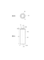
- FIG. 2A shows a front view of a battery cell included in the battery pack shown in FIG. 1
- FIG. 2B shows a plan view thereof.
- 3A shows a perspective view
- FIG. 3B shows a plan view
- FIG. 3C shows a side view
- FIG. 3D shows a front view of a battery tab included in the battery pack shown in FIG.
- FIG. 3D is an enlarged view of an area IV surrounded by a dotted line in FIG. 3A, showing a protrusion formed on a battery tab.
- FIG. 5A shows a process of spot welding a battery cell to a first battery cell
- FIG. 5B shows a process of projection welding a second battery cell to a battery tab fixed to the first battery cell.
- an embodiment of the battery pack 1 includes a first battery cell 10A and a second battery cell 10B that are connected in series and arranged in a straight line.
- the A and B attached to the reference characters indicating the battery cells and their components indicate the first battery cell and the second battery cell, and when there is no A or B, it will be described as to which battery cell and its component it corresponds to.
- a battery tab 20 is disposed between the positive electrode terminal 11A of the first battery cell 10A and the negative electrode terminal 12B of the second battery cell 10B, and the first battery cell 10A and the second battery cell 10B are electrically connected in series via the battery tab 20, and are arranged in a straight line in the order of the first battery cell 10A, the battery tab 20, and the second battery cell 10B.
- the battery cell 10 is a bare cell of AA size and has a conductive outer tube 13.
- the outer tube 13 has a bottomed cylindrical shape with one open end and a central axis X.
- the diameter D1 of the outer tube 13 is 13.9 mm, and the length L1 in the tube axis direction is 48.8 cm.
- the positive terminal 11 is attached to the open end of the outer tube 13 via a sealing body.
- the positive terminal 11 is cylindrical with a diameter D2 of 7 mm and is attached concentrically with the outer tube 13.
- the length L2 of the positive terminal 11 protruding from one end of the outer tube 13 is 0.7 mm.
- the bottom wall corresponding to the other end of the outer tube 13 functions as the negative terminal 12.
- the first battery cell 10A has a positive terminal 11A at one end of the outer tube 13A in the direction of the central axis XA, and a negative terminal 12A at the other end.
- the second battery cell 10B has a positive terminal 11B at one end of the outer casing 13B in the direction of the central axis XB, and a negative terminal 12B at the other end.
- the battery tab 20 electrically connects the first battery cell 10A and the second battery cell 10B, and also functions as a welding electrode receptacle for constructing the battery pack 1.
- the battery tab 20 is made of a nickel plate with a nearly rectangular outline. As shown in Figures 3A and 3C, the battery tab 20 is bent at a parallel line portion closer to one short side than the other short side to form a bent portion 21.
- the bent portion 21 divides the battery tab 20 into a welded plate portion 22 and a conductive plate portion 23.
- the conductive plate portion 23 extends in a direction nearly perpendicular to the in-plane direction of the welded plate portion 22 due to the bending from the bent portion 21.
- the welded plate portion 22 has a generally rectangular shape with a long side length L3 of 11.2 mm and a short side length L4 of 7.5 mm.
- the short side length L4 of the welded plate portion 22 can be any suitable value as long as it is smaller than the diameter D1 of the outer casing 13.
- the welded plate portion 22 also has two projections 24, 24 for projection welding on one surface 22A, and the other surface 22B is flat.
- the projections 24 have a dome shape with a diameter of 1 mm, as shown in Figure 4.
- the projections 24 are welded to the negative terminal 12B of the second battery cell 10B by projection welding, electrically connecting the battery tab 20 to the second battery cell 10B.
- the conductive plate portion 23 is continuous with the welded plate portion 22, and is located radially outside the exterior tube 13A of the first battery cell 10A when the other surface 22B of the welded plate portion 22 is welded to the positive terminal 11A of the first battery cell 10A.
- the conductive plate portion 23 has the function of passing a current through the welded plate portion 22 during projection welding.
- an opening 25 including a part of the bending portion 21 is formed across the welded plate portion 22 and the conductive plate portion 23.
- the battery tab 20 is fixed to the first battery cell 10A. As shown in FIG. 5A, the battery tab 20 is arranged so as to contact the positive electrode terminal 11A of the first battery cell 10A. The other surface 22B of the welding plate portion 22 of the battery tab 20 is arranged to face the positive electrode terminal 11A, and the conductive plate portion 23 is arranged so as to be located radially outside the outer casing tube 13A. Next, two electrode rods 30, 30 for spot welding are pressed against one surface 22A of the welding plate portion 22, and the battery tab 20 is spot-welded to the positive electrode terminal 11A of the first battery cell 10A using the electrode rods 30, 30.
- the battery tab 20 is fixed to the first battery cell 10A and electrically connected to the first battery cell 10A.
- the electrode rods are removed.
- the electrode rods 30, 30 are pressed against the welding plate portion 22 of the battery tab 20 while avoiding the protrusions 24.
- the second battery cell 10B is arranged so that the negative terminal 12B (the bottom wall of the exterior tube 13) of the second battery cell 10B contacts the battery tab 20 fixed to the first battery cell 10A.
- the negative terminal 12B of the second battery cell 10B is arranged so that it abuts against two protrusions 24, 24 of the welding plate portion 22 of the battery tab 20.
- the second battery cell 10B is aligned with the first battery cell 10A so that an extension line of the central axis XA of the first battery cell 10A overlaps with the central axis XB of the second battery cell 10B. After alignment, the positive side of the second battery cell 10B is pressed in the central axis direction toward the first battery cell 10A.
- the welding plate portion 22 of the battery tab 20 and the second battery cell 10B are projection welded.
- Two electrode rods 41, 42 are used for projection welding.
- One electrode rod 41 is pressed against the current-carrying plate portion 23 of the battery tab 20 from the radial outside of the second battery cell 10B, and supplies power to the welding plate portion 22 via the current-carrying plate portion 23.
- the other electrode rod 42 is pressed against the side of the exterior tube 13 on the opposite side to the welding plate portion 22 with respect to the central axis XB of the second battery cell 10B.
- the welding plate portion 22 heats up and softens.
- the second battery cell 10B is pressed toward the first battery cell 10A, so that the protrusion 24 of the welding plate portion 22 is crushed and welded to the negative terminal of the second battery cell 10B.
- the temperature of the battery tab 20 drops and the welded portion between the battery tab 20 and the negative terminal of the second battery cell 10B solidifies, so that the welding plate portion 22 of the battery tab 20 is fixed to the negative terminal 12B of the second battery cell 10B around the protrusion 24 of the battery tab 20.
- an insulator 43 is placed between the current-carrying plate portion 23 and the side surface of the exterior tube 13B of the second battery cell 10B.
- the second battery cell 10B is fixed to the battery tab 20 by the protrusion 24 of the battery tab 20, so that the second battery cell 10B is electrically connected to the first battery cell 10A via the battery tab 20.
- the second battery cell 10B is linearly connected in series with the first battery cell 10A.
- the first battery cell 10A and the second battery cell 10B are positioned when the second battery cell 10B is projection welded to the battery tab 20, and the subsequent process does not involve deformation of the battery tab 20. Therefore, the battery pack 1 can be manufactured while maintaining the first battery cell 10A and the second battery cell 10B in a positioned state.
- a battery tab consisting of a welded plate portion and a conductive plate portion is used to projection weld the negative terminal of one battery cell to the battery tab 20 fixed to the positive terminal of the other battery cell, thereby enabling the two battery cells that are electrically connected in series to be arranged in a straight line with high precision in a simpler manner than before.
- Arranged in a straight line means that the central axes of the two cylindrical battery cells form a straight line.
- projection welding can be performed easily by simply abutting electrode rods against the conductive plate portion of the battery tab located on the radial outside of the battery cell and the side of the exterior tube of the battery cell to be welded to the battery tab.
- the position of the bent portion of the battery tab can be appropriately selected.
- the number of protrusions provided on the battery tab for projection welding may be three or more.
- the present disclosure is not limited to cylindrical battery cells, but can also be applied to cylindrical battery cells that have a shape that requires alignment of the central axis of the exterior tube between two adjacent battery cells, such as rectangular battery cells that are electrically connected in series in a linear manner.
Landscapes
- Chemical & Material Sciences (AREA)
- Chemical Kinetics & Catalysis (AREA)
- Electrochemistry (AREA)
- General Chemical & Material Sciences (AREA)
- Engineering & Computer Science (AREA)
- Mechanical Engineering (AREA)
- Connection Of Batteries Or Terminals (AREA)
- Resistance Welding (AREA)
- Battery Mounting, Suspending (AREA)
Abstract
直線状に配列され且つ電気的に直列接続された電池セルの中心軸同士の位置合わせが容易であり位置合わせ精度を向上する、組電池及び組電池の作製方法を提供する。組電池(1)は、各々が導電性且つ筒状の外装管(13)を有し、直線状に且つ直列に配列された第1及び第2電池セル(10A,10B)を有する。第1の電池セル(10A)の正極端子と第2の電池セル(10B)の負極端子との間に両電池セル(10A,10B)を電気的に直列接続する電池タブ(20)が配置される。電池タブ(20)は、両電池セル(10A,10B)の間に配置される溶接プレート部(22)と、溶接プレート部(22)に連続して外装管(13)の径方向外側に位置する通電プレート部(23)とを有する。溶接プレート部(22)は、第2の電池セル(10B)の負極端子と対向する面に、プロジェクション溶接により負極端子に固着される2つの突起部(24)を有する。
Description
本発明は、組電池及びその作製方法に関し、特に、電池セルを直線状に配列して電気的に直列接続された組電池とその作製方法とに関する。
従来、組電池において、2つの円筒形電池セルを直線状に直列接続するためには、以下に記載する方法が取られている。円筒形電池セルを直線状に直列接続するとは、電気的に直列接続された2つの電池セルを、一方の電池セルの中心軸と、他方の電池セルの中心軸とが一直線になるように一方及び他方の電池セルを配列させる構成である。
最初に、2つの電池セルが、一方の電池セルの正極端子に対し他方の電池セルの負極端子が中心軸とほぼ直交する方向において互いに近接するように、並列に配置される。次に、一方側に位置する2つ電池セルの正極端子と負極端子とを電池タブによりシリーズ溶接して、2つの電池セルを電気的に直列接続する。その後、電池タブを中間部で折り曲げて直線状に配列する。
従来の組電池では、シリーズ溶接された電池タブを折り曲げて電池セルの配列を並列から直線状に変更していた。このため、円筒形電池セルを中心軸方向に沿って直線状に配列させるとき、中心軸方向に隣り合う電池セルの中心軸同士の位置合わせが難しく、位置ずれの原因となっていた。
本発明の目的は、直線状に配列され且つ電気的に直列接続される電池セルの中心軸同士の位置合わせが容易であり位置合わせ精度を向上することができる組電池及び組電池の作製方法を提供することである。
本発明に係る組電池の一態様は、各々が導電性且つ筒状の外装管を有し、直線状に配列され且つ電気的に直列接続された第1及び第2電池セルを有する組電池であって、前記第1電池セルの正極端子と前記第2電池セルの負極端子との間に配置されて前記第1電池セルと前記第2電池セルとを電気的に接続する電池タブを有し、前記電池タブは、前記第1電池セルと前記第2電池セルとの間に位置する溶接プレート部と、前記溶接プレート部に連続して前記外装管の径方向外側に位置する通電プレート部とを有し、前記溶接プレート部は、前記第2電池セルの前記負極端子と対向する面に、前記電池タブと前記第2電池セルの前記負極端子とのプロジェクション溶接により前記負極端子に固着される少なくとも2つの突起部を有する。
本発明に係る組電池の作製方法の一態様は、各々が筒状の外装管を有する第1及び第2電池セルが直線状に配列され且つ電気的に直列接続された組電池を作製する、組電池の作製方法であって、電池タブを前記第1電池セルの正極端子に溶接する第1溶接工程であって、前記電池タブは、前記第1電池セルの正極端子に固定される溶接プレート部と、前記溶接プレート部に連続して前記第1電池セルの径方向外側に位置する通電プレート部とを有し、前記溶接プレート部の前記正極端子に対するスポット溶接を含む、第1溶接工程と、前記第1電池セルに溶接された前記溶接プレート部に、前記第2電池セルの負極端子を接触させて、前記第1電池セルに対して前記第2電池セルを一直線状に位置合わせする位置合わせ工程と、一直線状に位置合わせされた前記第1電池セル及び前記第2電池セルに対し、前記通電プレート部と前記外装管との間に絶縁体を介在させた状態で、前記溶接プレート部を前記第2電池セルの前記負極端子にプロジェクション溶接する第2溶接工程と、を有する。
本発明によれば、直線状に配列され且つ電気的に直列接続された電池セルの中心軸同士の位置合わせが容易であり位置合わせを精度良く行うことができる。
実施の形態について図面を参照しながら以下に説明する。
図1に示すように、一実施の形態である組電池1は、直列接続されるとともに一直線状に配列された第1電池セル10Aと第2電池セル10Bを含む。なお、以下の説明において、電池セル及びその構成部品を示す参照符号に付されたA及びBは、第1電池セル及び第2電池セルを示し、AまたはBが無いときは、どちらの電池セル及びその構成部品に該当するものとして記載する。詳細には、第1電池セル10Aの正極端子11Aと、第2電池セル10Bの負極端子12Bとの間に電池タブ20が配置され、電池タブ20を介して第1電池セル10Aと第2電池セル10Bとは電気的に直列接続されるとともに、第1電池セル10A、電池タブ20及び第2電池セル10Bの順に直線状に配列されている。
電池セル10は、AAサイズのベアセルであり、導電性の外装管13を有する。外装管13は、一端が開口するとともに中心軸Xを有する有底円筒形状を有する。外装管13の直径D1は、13.9mmであり、管軸方向の長さL1は、48.8cmである。外装管13の開口端に、正極端子11が封口体を介して取り付けられている。正極端子11は、直径D2が7mmの円筒形であり、外装管13と同心に取り付けられる。正極端子11の外装管13の一端から突出する長さL2は、0.7mmである。外装管13の他端に相当する底壁は、負極端子12として機能する。本実施の形態において、第1電池セル10Aは、外装管13Aの中心軸XA方向の一端に正極端子11Aを有し、他端に負極端子12Aを有する。第2電池セル10Bは、外装管13Bの中心軸XB方向の一端に正極端子11Bを有し、他端に負極端子12Bを有する。
電池タブ20は、第1電池セル10A及び第2電池セル10Bを電気的に接続するとともに、組電池1を作製するための溶接用電極受としても機能する。電池タブ20は、輪郭がほぼ長方形のニッケルプレートからなる。電池タブ20は、図3A及び図3Cに示すように、一方の短辺に他方の短辺よりも近接し且つ平行な線条箇所を折曲部21として折り曲げられている。折曲部21により、電池タブ20は、溶接プレート部22と通電プレート部23とに分けられる。本実施の形態において、通電プレート部23は、折曲部21からの折曲により、溶接プレート部22の面内方向とほぼ直交する方向に延在する。
溶接プレート部22は、図3B及び図3Dに示すように、長辺の長さL3が11.2mm、短辺の長さL4が7.5mmのほぼ長方形を有する。溶接プレート部22の短辺の長さL4は、外装管13の直径D1より小さければ適宜の値を取ることができる。また、溶接プレート部22は、一方の面22Aにプロジェクション溶接用に2つの突起24、24を有し、他方の面22Bは平坦である。突起24は、図4に示すように直径が1mmのドーム形状を有する。突起24は、プロジェクション溶接により、第2電池セル10Bの負極端子12Bに溶着され、電池タブ20を第2電池セル10Bに電気的に接続する。
通電プレート部23は、溶接プレート部22に連続し、溶接プレート部22の他方の面22Bが第1電池セル10Aの正極端子11Aに溶着されるときに、第1電池セル10Aの外装管13Aの径方向外側に位置する。通電プレート部23は、プロジェクション溶接時に溶接プレート部22に電流を流す機能を有する。
電池タブ20は、電池タブ20そのものの軽量化を図るとともに、容易に折り曲げ可能とするために、折曲部21の一部を含む開口25が、溶接プレート部22と通電プレート部23とに亘って形成されている。
次に、第1電池セル10A及び第2電池セル10Bを電気的に直列に接続する方法について説明する。
(1)第1電池セルと電池タブとの接続
最初に、電池タブ20を第1電池セル10Aに固着させる。図5Aに示すように、電池タブ20を第1電池セル10Aの正極端子11Aと接触するように配置する。電池タブ20の溶接プレート部22の他方の面22Bを正極端子11Aと対向させ、且つ通電プレート部23が外装管13Aの径方向外側に位置するように配置する。次に、スポット溶接用の2本の電極棒30、30を溶接プレート部22の一方の面22Aに押し当て、電極棒30、30を使用して電池タブ20を第1電池セル10Aの正極端子11Aにスポット溶接する。これにより、電池タブ20は、第1電池セル10Aに固着されて、第1電池セル10Aと電気的に接続される。スポット溶接の終了後、電極棒を取り除く。なお、電極棒30、30は、突起24を避けて電池タブ20の溶接プレート部22に押し当てる。
最初に、電池タブ20を第1電池セル10Aに固着させる。図5Aに示すように、電池タブ20を第1電池セル10Aの正極端子11Aと接触するように配置する。電池タブ20の溶接プレート部22の他方の面22Bを正極端子11Aと対向させ、且つ通電プレート部23が外装管13Aの径方向外側に位置するように配置する。次に、スポット溶接用の2本の電極棒30、30を溶接プレート部22の一方の面22Aに押し当て、電極棒30、30を使用して電池タブ20を第1電池セル10Aの正極端子11Aにスポット溶接する。これにより、電池タブ20は、第1電池セル10Aに固着されて、第1電池セル10Aと電気的に接続される。スポット溶接の終了後、電極棒を取り除く。なお、電極棒30、30は、突起24を避けて電池タブ20の溶接プレート部22に押し当てる。
(2)電池タブと第2電池セルとの接続
次に、図5Bに示すように、第1電池セル10Aに固定された電池タブ20に、第2電池セル10Bの負極端子12B(外装管13の底壁)が接触するように第2電池セル10Bを配置する。詳細には、第2電池セル10Bの負極端子12Bが、電池タブ20の溶接プレート部22の2つの突起24、24に当接するように配置する。さらに、第1電池セル10Aの中心軸XAの延長線と、第2電池セル10Bの中心軸XBとが重なるように、第2電池セル10Bを第1電池セル10Aに対して位置合わせする。位置合わせの後、第2電池セル10Bの正極側を第1電池セル10Aに向けて中心軸方向に押圧する。
次に、図5Bに示すように、第1電池セル10Aに固定された電池タブ20に、第2電池セル10Bの負極端子12B(外装管13の底壁)が接触するように第2電池セル10Bを配置する。詳細には、第2電池セル10Bの負極端子12Bが、電池タブ20の溶接プレート部22の2つの突起24、24に当接するように配置する。さらに、第1電池セル10Aの中心軸XAの延長線と、第2電池セル10Bの中心軸XBとが重なるように、第2電池セル10Bを第1電池セル10Aに対して位置合わせする。位置合わせの後、第2電池セル10Bの正極側を第1電池セル10Aに向けて中心軸方向に押圧する。
次に、電池タブ20の溶接プレート部22と第2電池セル10Bとをプロジェクション溶接する。プロジェクション溶接用に2本の電極棒41、42が使用される。一方の電極棒41は、電池タブ20の通電プレート部23に対し第2電池セル10Bの径方向外側から押し当てられ、通電プレート部23を経て溶接プレート部22に給電する。他方の電極棒42を、第2電池セル10Bの中心軸XBに対して溶接プレート部22とは反対側の外装管13の側面に押し当てる。
電極棒41、42を用いて通電を開始すると、溶接プレート部22は昇温軟化し、同時に、第2電池セル10Bは第1電池セル10Aに向けて押圧されているので、溶接プレート部22の突起24は、圧潰して第2電池セル10Bの負極端子に溶着される。通電を止めると、電池タブ20は温度が下がり、電池タブ20と第2電池セル10Bの負極端子との溶着部は固化するので、電池タブ20の突起24を中心にして電池タブ20の溶接プレート部22は、第2電池セル10Bの負極端子12Bに固定される。なお、このとき、電流が通電プレート部23から直接外装管13Bに流れることを防止するために、通電プレート部23と第2電池セル10Bの外装管13B側面との間に絶縁体43を配置する。
このようにして、電池タブ20の突起24により、電池タブ20に第2電池セル10Bは固着されるので、第2電池セル10Bは、電池タブ20を介して第1電池セル10Aと電気的に接続される。すなわち、第2電池セル10Bは、第1電池セル10Aと直線的に直列接続される。
第1電池セル10Aと第2電池セル10Bとは、電池タブ20に第2電池セル10Bをプロジェクション溶接するときに位置決めされ、その後の工程に電池タブ20の変形を含まない。したがって、第1電池セル10Aと第2電池セル10Bとの位置決めされた状態を維持しながら、組電池1を作製することができる。
このように、2つの電池セルを直線的に配列して電気的に直列接続するとき、溶接プレート部及び通電プレート部からなる電池タブを使用して、一方の電池セルの正極端子に固定された電池タブ20に他方の電池セルの負極端子をプロジェクション溶接することにより、従来よりも簡単な方法で電気的に直列接続される2つの電池セルを直線状に精度良く配列させることができる。直線状に配列するとは、2つの筒状の電池セルの中心軸が一直線を形成することを意味する。
また、従来のように、並列に配置された電池セルの一端側の対をなす正極端子および負極端子を単一の電池タブをスポット溶接により接続して、電池タブを折り曲げて直線状に配列を変更して作製される組電池に比べて、2つの電池セルを精度よく直線状に直列接続させることができる。これにより、従来より簡単な工程で組電池1の寸法精度を改善することができる。
さらに、プロジェクション溶接を行うとき、電池セルの径方向外側に位置する電池タブの通電プレート部と、電池タブと溶接される電池セルの外装管の側面とに、それぞれ電極棒をそれぞれ当接させれば良いので、簡単に行うことができる。
なお、上記実施の形態において、電池タブの折曲部の位置は、適宜の位置を取ることができる。
また、電池タブにプロジェクション溶接用に設けられる突起の数は3個以上であっても良い。
さらに、本開示は、円筒形の電池セルに限らず、直線状に電気的に直列接続される角型電池セルなど、隣り合う2つの電池セルの間で外装管の中心軸方向の位置合わせが必要な形状を有する筒状の電池セルに適用することができる。
2022年9月30日出願の特願2022-157596の日本出願に含まれる明細書、図面および要約書の開示内容は、すべて本願に援用される。
1 組電池
10 電池セル
10A 第1電池セル
10B 第2電池セル
11、11A、11B 正極端子
12、12A、12B 負極端子
13、13A、13B 外装管
20 電池タブ
22 溶接プレート部
23 通電プレート部
24 突起
43 絶縁体
10 電池セル
10A 第1電池セル
10B 第2電池セル
11、11A、11B 正極端子
12、12A、12B 負極端子
13、13A、13B 外装管
20 電池タブ
22 溶接プレート部
23 通電プレート部
24 突起
43 絶縁体
Claims (3)
- 各々が導電性且つ筒状の外装管を有し、直線状に配列され且つ電気的に直列接続された第1及び第2電池セルを有する組電池であって、
前記第1電池セルの正極端子と前記第2電池セルの負極端子との間に配置されて前記第1電池セルと前記第2電池セルとを電気的に接続する電池タブを有し、
前記電池タブは、前記第1電池セルと前記第2電池セルとの間に位置する溶接プレート部と、前記溶接プレート部に連続して前記外装管の径方向外側に位置する通電プレート部とを有し、
前記溶接プレート部は、前記第2電池セルの前記負極端子と対向する面に、前記電池タブと前記第2電池セルの前記負極端子とのプロジェクション溶接により前記負極端子に固着される少なくとも2つの突起部を有する、組電池。 - 各々が筒状の外装管を有する第1及び第2電池セルが直線状に配列され且つ電気的に直列接続された組電池を作製する、組電池の作製方法であって、
電池タブを前記第1電池セルの正極端子に溶接する第1溶接工程であって、前記電池タブは、前記第1電池セルの正極端子に固定される溶接プレート部と、前記溶接プレート部に連続して前記第1電池セルの径方向外側に位置する通電プレート部とを有し、前記溶接プレート部の前記正極端子に対するスポット溶接を含む、第1溶接工程と、
前記第1電池セルに溶接された前記溶接プレート部に、前記第2電池セルの負極端子を接触させて、前記第1電池セルに対して前記第2電池セルを一直線状に位置合わせする位置合わせ工程と、
一直線状に位置合わせされた前記第1電池セル及び前記第2電池セルに対し、前記通電プレート部と前記外装管との間に絶縁体を介在させた状態で、前記溶接プレート部を前記第2電池セルの前記負極端子にプロジェクション溶接する第2溶接工程と、を有する、組電池の作製方法。 - 前記溶接プレート部は、前記第2電池セルの前記負極端子と対向する面に、前記溶接プレート部と前記第2電池セルの前記負極端子とのプロジェクション溶接により前記負極端子に固着される少なくとも2つの突起部を有する、請求項2記載の組電池の作製方法。
Applications Claiming Priority (2)
| Application Number | Priority Date | Filing Date | Title |
|---|---|---|---|
| JP2022157596A JP2025168597A (ja) | 2022-09-30 | 2022-09-30 | 組電池及びその作製方法 |
| JP2022-157596 | 2022-09-30 |
Publications (1)
| Publication Number | Publication Date |
|---|---|
| WO2024071192A1 true WO2024071192A1 (ja) | 2024-04-04 |
Family
ID=90477814
Family Applications (1)
| Application Number | Title | Priority Date | Filing Date |
|---|---|---|---|
| PCT/JP2023/035135 Ceased WO2024071192A1 (ja) | 2022-09-30 | 2023-09-27 | 組電池及びその作製方法 |
Country Status (2)
| Country | Link |
|---|---|
| JP (1) | JP2025168597A (ja) |
| WO (1) | WO2024071192A1 (ja) |
Citations (1)
| Publication number | Priority date | Publication date | Assignee | Title |
|---|---|---|---|---|
| JP2009009852A (ja) * | 2007-06-28 | 2009-01-15 | Sanyo Electric Co Ltd | 電池モジュール |
-
2022
- 2022-09-30 JP JP2022157596A patent/JP2025168597A/ja active Pending
-
2023
- 2023-09-27 WO PCT/JP2023/035135 patent/WO2024071192A1/ja not_active Ceased
Patent Citations (1)
| Publication number | Priority date | Publication date | Assignee | Title |
|---|---|---|---|---|
| JP2009009852A (ja) * | 2007-06-28 | 2009-01-15 | Sanyo Electric Co Ltd | 電池モジュール |
Also Published As
| Publication number | Publication date |
|---|---|
| JP2025168597A (ja) | 2025-11-10 |
Similar Documents
| Publication | Publication Date | Title |
|---|---|---|
| JP5716398B2 (ja) | 電池及びその製造方法 | |
| JP5635646B2 (ja) | 圧入タイプのリベットを用いる無溶接タイプのバッテリパック | |
| JP6107266B2 (ja) | 二次電池および二次電池の製造方法 | |
| US8715850B2 (en) | Battery module and method of manufacturing the same | |
| JP3312853B2 (ja) | 電池間接続構造 | |
| EP2264808A1 (en) | Sealed battery and producing method therefor | |
| JP4787046B2 (ja) | 円筒状のリチウム二次電池 | |
| US20250112339A1 (en) | Current collecting plate and battery unit comprising current collecting plate | |
| CN109565024A (zh) | 电池模块 | |
| CN119999004A (zh) | 电池单体及其装配方法、电池、用电装置和装配组件 | |
| JP2011054338A (ja) | 電極接続構造および電極接続方法 | |
| KR101232783B1 (ko) | 이차 전지 및 그 제조 방법 | |
| CN112913071A (zh) | 含外覆或外包材料接触板的电池模块 | |
| JP4146000B2 (ja) | 電池間接続構造 | |
| JP3092923B2 (ja) | 電池間接続構造、その方法、電池、電池モジュール、その製造方法 | |
| WO2024071192A1 (ja) | 組電池及びその作製方法 | |
| JP2019067580A (ja) | 蓄電素子 | |
| EP1139463B1 (en) | Method and apparatus for manufacturing battery module and unit battery cell for use in battery module | |
| JP4373049B2 (ja) | 蓄電池 | |
| CN118541867A (zh) | 电池单元 | |
| JP2004213937A (ja) | 電池 | |
| JPWO2019116914A1 (ja) | 蓄電素子 | |
| CN210615627U (zh) | 电芯固定装置及焊接设备 | |
| JP2017091723A (ja) | 蓄電装置の製造方法、及び蓄電装置 | |
| KR101039518B1 (ko) | 전지셀 접속부재 |
Legal Events
| Date | Code | Title | Description |
|---|---|---|---|
| 121 | Ep: the epo has been informed by wipo that ep was designated in this application |
Ref document number: 23872414 Country of ref document: EP Kind code of ref document: A1 |
|
| NENP | Non-entry into the national phase |
Ref country code: DE |
|
| 122 | Ep: pct application non-entry in european phase |
Ref document number: 23872414 Country of ref document: EP Kind code of ref document: A1 |
|
| NENP | Non-entry into the national phase |
Ref country code: JP |