WO2024070979A1 - 画像処理装置、画像処理方法、プログラム及び撮像装置 - Google Patents
画像処理装置、画像処理方法、プログラム及び撮像装置 Download PDFInfo
- Publication number
- WO2024070979A1 WO2024070979A1 PCT/JP2023/034587 JP2023034587W WO2024070979A1 WO 2024070979 A1 WO2024070979 A1 WO 2024070979A1 JP 2023034587 W JP2023034587 W JP 2023034587W WO 2024070979 A1 WO2024070979 A1 WO 2024070979A1
- Authority
- WO
- WIPO (PCT)
- Prior art keywords
- image
- distance image
- distance
- light
- pixel
- Prior art date
- Legal status (The legal status is an assumption and is not a legal conclusion. Google has not performed a legal analysis and makes no representation as to the accuracy of the status listed.)
- Ceased
Links
Images







Classifications
-
- G—PHYSICS
- G01—MEASURING; TESTING
- G01B—MEASURING LENGTH, THICKNESS OR SIMILAR LINEAR DIMENSIONS; MEASURING ANGLES; MEASURING AREAS; MEASURING IRREGULARITIES OF SURFACES OR CONTOURS
- G01B11/00—Measuring arrangements characterised by the use of optical techniques
- G01B11/24—Measuring arrangements characterised by the use of optical techniques for measuring contours or curvatures
- G01B11/25—Measuring arrangements characterised by the use of optical techniques for measuring contours or curvatures by projecting a pattern, e.g. one or more lines, moiré fringes on the object
-
- G—PHYSICS
- G06—COMPUTING OR CALCULATING; COUNTING
- G06T—IMAGE DATA PROCESSING OR GENERATION, IN GENERAL
- G06T7/00—Image analysis
- G06T7/50—Depth or shape recovery
Definitions
- This disclosure relates to an image processing device, an image processing method, a program, and an imaging device.
- a 3D point cloud is generated based on a distance image of an area including an object.
- This distance image is an image in which distance information is reflected for each pixel.
- This distance image can be generated by projecting light having a specific emission pattern (structured light) onto an object and acquiring distance information from an image of the light reflected from the object.
- This image includes an image of the pattern light in which the emission pattern projected onto the object is deformed according to the distance to the object. The distance to the object is calculated by comparing the image of this pattern light with the original emission pattern, and stored in each pixel, allowing the distance image to be generated.
- the above conventional technology has a problem in that the amount of data in the distance image increases.
- the distance to the part of the object at the position of the light emission pattern projected onto the object is calculated, and the distance to the area of the object not illuminated by the light emission pattern is not calculated.
- the distance image contains pixels having distance information arranged irregularly and discretely, and many pixels having no distance information. This causes a problem in that the amount of data in the distance image increases.
- processing time increases.
- an image processing device an image processing method, a program, and an imaging device that generate distance images with reduced data volume.
- the image processing device of the present disclosure has a second distance image generating unit.
- the second distance image generating unit generates a second distance image, which is a distance image having a plurality of second pixels in which distance information of a first pixel, which is a pixel of a first distance image that is a distance image of an area including an object, is placed, and the plurality of second pixels are placed corresponding to the light-emitting areas of structured light having a predetermined light-emitting area pattern that is projected onto the area including the object to generate the first distance image, and the distance information of the first pixel at a position corresponding to the light-emitting area is placed in the second pixel at a position corresponding to the light-emitting area.
- FIG. 1 is a diagram illustrating a configuration example of a robot arm according to an embodiment of the present disclosure.
- 1 is a diagram illustrating an example of the configuration of an imaging device according to a first embodiment of the present disclosure.
- FIG. 2 is a diagram illustrating a configuration example of a post-processing unit according to an embodiment of the present disclosure.
- FIG. 13 is a diagram illustrating an example of generation of a distance image according to an embodiment of the present disclosure.
- FIG. 13 is a diagram illustrating an example of generation of a distance image according to an embodiment of the present disclosure.
- 11A to 11C are diagrams illustrating an example of generation of a second distance image according to an embodiment of the present disclosure.
- FIG. 1 is a diagram illustrating an example of position and orientation estimation according to an embodiment of the present disclosure.
- FIG. 11 is a diagram illustrating an example of a processing procedure of a process of a control system according to an embodiment of the present disclosure.
- FIG. 11 is a diagram illustrating an example of a processing procedure of distance measurement processing according to an embodiment of the present disclosure.
- FIG. 11 is a diagram illustrating an example of a processing procedure of a three-dimensional point cloud generation process according to an embodiment of the present disclosure.
- FIG. 11 is a diagram illustrating an example of the configuration of an imaging device according to a second embodiment of the present disclosure.
- FIG. 11 is a diagram illustrating an example of a data amount reduction process according to a second embodiment of the present disclosure.
- FIG. 1 is a diagram illustrating a configuration example of a robot arm according to an embodiment of the present disclosure.
- the diagram illustrates a robot arm 1 to which an imaging device according to an embodiment of the present disclosure can be applied.
- the robot arm 1 is a device that performs tasks such as grasping and carrying an object in place of a human arm.
- the robot arm 1 in the diagram includes a plurality of links that are each rotatably attached.
- the links are parts that correspond to the arm bones of the robot arm 1.
- a gripper 2 that grips an object to be transported is disposed at the tip of the robot arm 1.
- the robot arm 1 extends, contracts, and rotates based on the control of a control device (not shown), and can transport the grasped object to any position within a movable range.
- the figure shows an example in which a robot arm 1 grasps an object 3 being transported by a conveyor belt 4 and transports it to a predetermined position, such as a workpiece.
- An imaging device 10 is disposed at the tip of the robot arm 1.
- This imaging device 10 has an imaging element (image element 110, described later) and generates an image of the area near the conveyor belt 4 within the movable range of the robot arm 1.
- An image processing device (image processing device 100, described later) is disposed in the imaging device 10, and a distance image of the object 3 is generated from the image generated by the imaging element 110 and transmitted to a post-processing unit 20, described later.
- the post-processing unit 20 includes an image processing unit 200 and a mechanism control unit 210 that controls the robot arm 1.
- the image processing unit 200 generates a three-dimensional point cloud of the object 3 based on the distance image generated by the image processing device 100, and detects the position and orientation of the object 3.
- the mechanism control unit 210 also controls the movement of the robot arm 1 based on the position and orientation of the object 3, and drives the gripper 2 to grip the object 3.
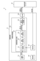
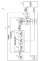
- [Configuration of the image processing device] 2 is a diagram showing an example of the configuration of an imaging device according to the first embodiment of the present disclosure.
- the figure is a block diagram showing an example of the configuration of the imaging device 10.
- a post-processing unit 20 is further illustrated in the figure.
- the imaging device 10 and the post-processing unit 20 constitute a control system 9.
- the imaging device 10 includes an imaging element 110, a distance image generating unit 120, a second distance image generating unit 130, an interface (IF) unit 160, a holding unit 140, and a control unit 150.
- the distance image generating unit 120 and the second distance image generating unit 130 constitute an image processing device 100.
- the imaging element 110 generates an image.
- This imaging element 110 generates an image of an area including the object 3.
- a CMOS (Complementary Metal Oxide Semiconductor) type imaging element can be used for the imaging element 110.
- This CMOS type imaging element has an imaging surface on which a plurality of pixels that generate image signals are arranged in a two-dimensional lattice pattern. When light from the object 3 is incident on this imaging surface, each pixel on the imaging surface generates an image signal. One screen's worth of data of these image signals constitutes an image.
- the imaging element 110 sequentially generates images (frames) at a predetermined frame frequency and outputs them to the distance image generating unit 120.
- the imaging element 110 in the same figure generates an image of an area of the object 3 on which structured light having a predetermined pattern of light-emitting areas is projected to generate a distance image (a first distance image described later). This image is referred to as an imaging image. Details of the structured light will be described later. Note that the imaging element 110 is an example of a sensor.
- the distance image generating unit 120 generates a first distance image.
- This distance image generating unit 120 generates a first distance image from the captured image generated by the above-mentioned imaging element 110, and outputs it to the second distance image generating unit 130.
- This first distance image is a distance image of an area including the object 3, which is the subject of distance measurement, and has approximately the same pixel structure as the image generated by the imaging element 110.
- the pixels that make up this first distance image are referred to as first pixels.
- the distance image generating unit 120 includes a matching processing unit 121, a parallax calculation unit 122, and a distance calculation unit 123.
- the matching processing unit 121 performs pixel matching processing.
- This pixel matching processing corresponds pixels of the captured image generated by the image sensor 110 with pixels of a structured light pattern image, which is an image representing the structured light projected onto the object 3.
- This pixel matching processing makes it possible to detect pixels in the captured image that correspond to pixels having the pattern of the light-emitting area of the structured light in the structured light pattern image.
- the matching processing unit 121 outputs the combination of pixels of the structured light pattern image and pixels in the captured image detected by performing pixel matching processing to the parallax calculation unit 122.
- the parallax calculation unit 122 generates parallax, which is the difference between the positions of pixels in the structured light pattern image output from the matching processing unit 121 and pixels in the captured image.
- the parallax calculation unit 122 outputs the calculated parallax to the distance calculation unit 123.
- the distance calculation unit 123 calculates the distance based on the parallax output from the parallax calculation unit 122.
- the distance calculation can be performed based on the principle of triangulation.
- the distance calculation unit 123 stores information about the calculated distance in pixels that constitute a distance image at the same position as the pixels of the captured image output from the matching processing unit 121. By calculating the distance and storing the calculated distance for all pixels, it is possible to generate a distance image for one frame (first distance image).
- the generated first distance image is output to the second distance image generation unit 130.
- the second distance image generating unit 130 generates a second distance image based on the first distance image generated by the distance image generating unit 120. This second distance image generating unit 130 outputs the generated second distance image to the IF unit 160.
- the second distance image is a distance image having a plurality of second pixels in which distance information of the first pixel of the first distance image is arranged. The second distance image will be described in detail later.
- the IF section 160 is responsible for communication with the post-processing unit 20. This IF section 160 transmits the second distance image from the second distance image generating section 130 to the post-processing unit 20.
- the storage unit 140 stores the calibration parameters for distance calculation in the distance calculation unit 123.
- the storage unit 140 stores the calibration parameters output as setting values from the post-processing unit 20.
- the control unit 150 controls the entire image processing device 100.
- [Configuration of post-processing unit] 3 is a diagram showing an example of the configuration of a post-processing unit according to an embodiment of the present disclosure.
- the figure is a block diagram showing an example of the configuration of the post-processing unit 20.
- the post-processing unit 20 includes an image processing unit 200 and a mechanism control unit 210.
- the image processing unit 200 performs processing based on the distance image output from the image processing device 100.
- the image processing unit 200 includes a memory control unit 201, a memory 202, a 3D point cloud generation unit 203, a position and orientation detection unit 204, and a control unit 205.
- the memory 202 holds the second distance image transmitted from the imaging device 10.
- the memory 202 also stores data generated when the 3D point cloud is generated by the 3D point cloud generating unit 203.
- the memory control unit 201 controls the memory 202. This memory control unit 201 controls writing of the second distance image data to the memory 202. The memory control unit 201 also controls writing of the three-dimensional point cloud data generated by the position and orientation detection unit 204 to the memory 202. The position and orientation detection unit 204, which will be described later, detects the area of the object 3 based on the three-dimensional point cloud data written to the memory 202, and creates three-dimensional point cloud data.
- the three-dimensional point cloud generating unit 203 generates a three-dimensional point cloud. This three-dimensional point cloud generating unit 203 generates a three-dimensional point cloud from the second distance image and writes it to the memory 202.
- the position and orientation detection unit 204 detects the area of the object 3 from the three-dimensional point cloud, and estimates and detects the position and orientation of the detected object 3.
- the position and orientation detection unit 204 outputs the detected position and orientation of the object 3 to the mechanism control unit 210.
- the control unit 205 controls the entire image processing unit 200.
- the control unit 205 also generates setting values and outputs them to the holding unit 140 of the imaging device 10.
- the mechanism control unit 210 controls the robot arm 1.
- This mechanism control unit 210 includes a mechanism control unit 211.
- the mechanism control unit 211 controls the robot arm 1 and the gripping unit 2 based on the distance to the object 3 and the position of the object 3 output from the image processing unit 200. For example, the mechanism control unit 211 calculates control parameters for the camera 30 and the robot arm 1 from information on the position and orientation of the object 3 detected by the position and orientation detection unit 204, generates control signals, and transmits them to a drive mechanism (not shown).
- [Distance image generation] 4 is a diagram showing an example of distance image generation according to an embodiment of the present disclosure. This figure is a diagram showing an outline of generation of a first distance image in the distance image generation unit 120.
- the distance image generation unit 120 calculates the distance to the measurement object. The distance to the measurement object can be calculated based on the principle of triangulation by detecting feature points from a pattern projected onto the measurement object, associating the feature points with feature points on the captured image based on the feature amounts of the detected feature points.
- (A) in the figure shows an example in which structured light 369 is projected from projector 361 onto measurement object 350, and an image is generated by image sensor 110.
- Structured light 369 in the figure shows an example composed of a pattern of multiple vertical lines.
- (B) of the figure shows an example of a captured image 370.
- an image 372 that changes according to the shape of the measurement object 350 is formed, and in the other region, an image based on the structured light 369 (projected image 371) is formed.
- the matching processing unit 121 of the distance image generating unit 120 performs matching processing using the image 372.
- the matching processing unit 121 sets a feature point in the image 372. This feature point can be set to the edge of the light projection pattern, etc.
- the black dots in (B) of the figure show examples of feature points.
- the matching processing unit 121 calculates a feature amount from the pixel values around the set feature point.
- the matching processing unit 121 detects a pixel in the projected image 371 that has the same feature amount, and associates it with the set feature point.
- (C) of the figure shows an example of a case where a feature point (x, y) of the image 372 is associated with a point (xp, yp) of the projected image 371. In this manner, the matching process is performed by the matching processing unit 121.
- the disparity calculation unit 122 calculates the disparity between the feature point (x, y) and the point (xp, yp).
- the distance calculation unit 123 applies the principle of triangulation to calculate the distance (three-dimensional shape) to the measurement object 350 from the disparity between the feature point (x, y) and the point (xp, yp). By repeating such processing, a first distance image can be generated.
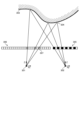
- FIG. 5 is a diagram showing an example of distance image generation according to an embodiment of the present disclosure.
- point 301 represents the virtual position of image sensor 110.
- point 302 represents the virtual position of projector 361.
- the thin lines in the figure represent light projected from projector 361, reflected by object 303, and incident on image sensor 110.
- lenses are typically placed at the positions of points 301 and 302 in the figure.
- Image sensor 110 and projector 361 are placed at positions of the focal lengths of these lenses.
- structured light image plane 305 of the projection surface of projector 361 is shown.
- a black rectangle on structured light image plane 305 represents the light-emitting area.
- the point where this structured light is reflected by object 303 becomes the measurement point that is the subject of distance measurement.
- Measurement point 304 is shown in the figure.
- Light reflected at measurement point 304 enters captured image plane 306 of image sensor 110.
- a dotted hatched rectangle on captured image plane 306 in the figure represents pixel 307 where reflected light from measurement point 304 enters.
- the captured image is composed of image signals generated by the pixels of captured image plane 306. Note that the "pixels" of the captured image, etc. represent data areas where image signals are stored.
- the light emitting regions are arranged at equal intervals.
- the pixels (pixels 307) on which the reflected light from the measurement points 304 on the captured image plane 306 is incident are irregularly arranged according to the shape of the target object 330.
- the white rectangles on the captured image plane 306 are pixels that are not irradiated with the structured light, and are therefore not subject to distance calculation.
- FIG. 6A shows a structured light image 310.
- This structured light image 310 shows the light-emitting and non-light-emitting regions of the structured light for each pixel, and is an image reflecting the light-emitting and non-light-emitting regions of the image plane 305 in FIG. 5.
- the black rectangles in the structured light image 310 represent pixels 311 in the light-emitting regions, and the white rectangles represent pixels 312 in the non-light-emitting regions.
- the light-emitting pattern of the structured light image 310 in the same figure shows an example formed of multiple vertical lines, similar to FIG. 4.
- FIG. 5 shows a first distance image 320.
- This first distance image 320 is data generated by the distance image generating unit 120 described in FIG. 2 based on an image composed of image signals generated by pixels arranged on the image plane 306 in FIG. 5.
- the rectangles in the first distance image 320 represent first pixels. These first pixels correspond one-to-one to the pixels of the image generated by the image sensor 110.
- the dot-hatched rectangles in the first distance image 320 represent first pixels 321 in the area where light from the measurement point 304 is incident.
- This first pixel 321 is the first pixel in which distance information is stored as a pixel value, and is the first pixel corresponding to pixel 307 in FIG. 5.
- the open rectangles represent first pixels 322 in the area where light from the measurement point 304 is not incident.
- the three light-emitting regions on the right side of the structured light image 310 correspond to the first pixels 321 in the three columns of the first distance image 320.
- (C) in the figure shows second distance image 340.
- This second distance image 340 is a distance image generated by second distance image generation unit 130 described in FIG. 2.
- Second distance image 340 is configured by arranging second pixels 341 having a configuration similar to that of structured light image 310.
- Second distance image generation unit 130 stores distance information of first pixel 321 in first distance image 320 in second pixel 341 at a position corresponding to pixel 311 in the light-emitting area of structured light pattern image 310.
- the multiple second pixels 341 of the second distance image 340 are arranged to correspond to the pixels 311 of the light-emitting area of the structured light that is projected onto an area including the target (object 3) to generate the first distance image 320, and distance information of the first pixel 321 at a position corresponding to the pixel 311 of the light-emitting area is arranged in the second pixel 341 at a position corresponding to the pixel 311 of the light-emitting area.
- the second distance image generation unit 130 can detect the position of the second pixel 341 using the result of pixel matching by the matching processing unit 121.
- the second distance image 340 corresponds to data from which the pixels of the first distance image 320 that do not have distance information have been removed.
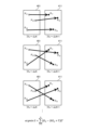
- FIG. 7 is a diagram showing an example of position and orientation estimation according to an embodiment of the present disclosure.
- This figure shows an example of position and orientation detection in the position and orientation detection unit 204.
- This figure also shows an example of estimating and detecting the position and orientation based on the ICP (Iterative Closest Point) algorithm.
- the position and orientation can be estimated by calculating a rotation matrix and a translation matrix that minimize the square sum from the positional relationship of the three-dimensional point cloud between frames. This calculation of the square sum and the movement of the point cloud are repeated until the convergence condition is satisfied.
- matrices R and T are obtained that minimize the difference value between Psn and Ptn (the square sum of the distance between corresponding points) when the rotation matrix (R) and the translation matrix (T) are applied in the correspondence relationship between Psn and Ptn.
- the formula in the figure shows a calculation formula for the square sum of the distance between corresponding points.
- the variation of corresponding points is defined within a specified range.
- the figure shows the variation of corresponding points in frame 401, which has point group Ps0-Ps2 and corresponds to frame N, and frame 411, which has point group Pt0-Pt2 and corresponds to frame N+1.
- the calculation of the sum of squares of the distances between these corresponding points and the movement of the point group are repeated until the sum of squares satisfies the convergence condition. This makes it possible to calculate the rotation matrix (R) and translation matrix (T), and to estimate the position and orientation of object 3 represented by the 3D point group.
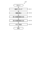
- FIG. 8 is a diagram showing an example of a processing procedure of the control system according to the embodiment of the present disclosure.
- the figure is a flow chart showing an example of a processing procedure of the control system 9 of FIG. 1.
- the image sensor 110 generates an image of the object 3, which is a target object (step S101)
- the image processing device 100 performs a distance measurement process (step S110) to generate a second distance image.
- the three-dimensional point cloud generating unit 203 performs a three-dimensional point cloud generating process (step S120) to generate a three-dimensional point cloud.
- the image processing unit 200 performs a process to reduce unnecessary three-dimensional point clouds (step S102).
- the position and orientation detection unit 204 detects the position and orientation of the object 3 based on the three-dimensional point cloud (step S103). After that, the mechanism control unit 211 of the mechanism control unit 210 controls the robot arm 1 and the gripping unit 2 based on the position and orientation of the object 3.
- FIG. 9 is a diagram showing an example of a processing procedure of distance measurement processing according to an embodiment of the present disclosure.
- the figure is a flow chart showing an example of a processing procedure of distance measurement processing in the image processing device 100.
- the processing in the figure corresponds to the processing in step S110 in FIG. 8.
- the matching processing unit 121 performs pixel matching (step S111).
- the parallax calculation unit 122 calculates parallax (step S112).
- the distance calculation unit 123 calculates the distance and generates a first distance image (step S113).
- the second distance image generation unit 130 generates a second distance image based on the first distance image (step S114).
- step S115 the image processing device 100 transfers the second distance image to the memory 202 of the post-stage processing unit 20 (step S115). After that, the image processing device 100 returns to the original processing.
- step S114 is an example of a "second distance image generation procedure" of the present disclosure.
- [3D point cloud generation process] 10 is a diagram showing an example of a processing procedure of a three-dimensional point cloud generation process according to an embodiment of the present disclosure.
- the figure is a flow chart showing an example of a processing procedure of a three-dimensional point cloud generation process in the three-dimensional point cloud generation unit 203.
- the processing in the figure corresponds to the processing of step S120 in FIG. 8.
- the three-dimensional point cloud generation unit 203 reads out pixel values of a distance image (second distance image) from the memory 202 (step S121).
- the three-dimensional point cloud generation unit 203 determines whether the read pixel values correspond to measurement points (step S122). As a result, if the pixel values do not correspond to the measurement points (step S122, No), the three-dimensional point cloud generation unit 203 proceeds to the processing of step S125.
- step S122 determines whether the pixel value corresponds to the measurement point (step S122, Yes).
- step S122 determines whether the pixel value corresponds to the measurement point (step S122, Yes).
- step S124 writes the calculated three-dimensional coordinate information to the memory 202 (step S124) and proceeds to the process of step S125.
- step S125 the three-dimensional point cloud generator 203 determines whether the three-dimensional point cloud generation process has ended (step S125). As a result, if the three-dimensional point cloud generation process has not ended (step S125, No), the three-dimensional point cloud generator 203 returns to the process of step S121. On the other hand, if the three-dimensional point cloud generation process has ended in step S125 (step S125, Yes), the three-dimensional point cloud generator 203 returns to the original process.
- the image processing device 100 of the first embodiment of the present disclosure generates a second distance image with a reduced amount of data from a first distance image including the object 3.
- the amount of calculations required for processing such as determining measurement points in the processing of the subsequent processing unit 20 can be reduced.
- the transfer time to the subsequent processing unit 20 can be shortened.
- the image processing device 100 of the first embodiment described above generates a second distance image by reducing the amount of data from the first distance image.
- the image processing device 100 of the second embodiment of the present disclosure differs from the first embodiment described above in that the amount of data of the second distance image is further reduced.
- FIG. 11 is a diagram showing a configuration example of an imaging device 10 according to a second embodiment of the present disclosure. Similar to Fig. 2, Fig. 11 is a block diagram showing a configuration example of the imaging device 10. The imaging device 10 in Fig. 11 differs from the imaging device 10 in Fig. 2 in that it further includes a data amount reduction unit 170 of the image processing device 100.
- the image processing device 100 in the figure includes a data amount reduction unit 170.
- This data amount reduction unit 170 reduces the amount of data of the second distance image output from the second distance image generation unit 130.
- the data amount reduction can be performed by a process of reducing some of the pixels of the second distance image.
- the data amount reduction unit 170 outputs the processed second distance image to the IF unit 160.
- [Data volume reduction process] 12 is a diagram showing an example of a data amount reduction process according to the second embodiment of the present disclosure.
- the data amount reduction process will be described using a second distance image 340 in the figure.
- the data amount can be reduced by thinning out second pixels 341 at a predetermined interval.
- the dashed rectangle in the figure represents the second pixels 341 to be deleted. Since the second distance image 340 has a regular arrangement of measurement points, it is possible to reduce the data amount by thinning out in this manner.
- the data amount reduction unit 170 can be configured to switch whether or not to perform the data amount reduction process for the second distance image based on the parameters stored in the storage unit 140. It is also possible to configure the thinning start position and thinning interval to be adjusted based on the parameters stored in the storage unit 140. In this case, the parameters are supplied as setting values from the post-processing unit 20.
- the rest of the configuration of the imaging device 10 is the same as the configuration of the imaging device 10 in the first embodiment of the present disclosure, so a description thereof will be omitted.
- the imaging device 10 of the second embodiment of the present disclosure can further reduce the amount of data in the second distance image.
- each device described in this specification may be realized using software, hardware, or a combination of software and hardware.
- the programs constituting the software are stored in advance, for example, in a storage medium (non-transitory media) provided inside or outside each device. Then, each program is loaded into RAM, for example, when executed by a computer, and executed by a processor such as a CPU.
- processing steps described in the above embodiments may be considered as a method having a series of steps, or as a program for causing the computer to execute the series of steps, or as a recording medium for storing the program.
- CDs Compact Discs
- MDs MiniDiscs
- DVDs Digital Versatile Discs
- memory cards Blu-ray (registered trademark) Discs, etc.
- Blu-ray (registered trademark) Discs, etc. can be used as this recording medium.
- the present technology can also be configured as follows.
- An image processing device having a second distance image generation unit that generates a second distance image, which is a distance image having a plurality of second pixels in which distance information of first pixels, which are pixels of a first distance image, which is a distance image of an area including an object, is placed, wherein the plurality of second pixels are placed corresponding to the light-emitting areas of structured light having a predetermined pattern of light-emitting areas that is projected onto the area including the object to generate the first distance image, and in which distance information of the first pixel at a position corresponding to the light-emitting area is placed in the second pixel at a position corresponding to the light-emitting area.
- the image processing device further comprising a data amount reduction unit that reduces the amount of data of the second distance image.
- An image processing method including: generating a second distance image, which is a distance image having a plurality of second pixels in which distance information of first pixels, which are pixels of a first distance image, which is a distance image of an area including an object, is placed, wherein the plurality of second pixels are placed corresponding to the light-emitting areas of structured light having a predetermined pattern of light-emitting areas that is projected onto the area including the object to generate the first distance image, and distance information of the first pixel at a position corresponding to the light-emitting area is placed in the second pixel at a position corresponding to the light-emitting area.
- a program that causes a computer to execute a second distance image generation procedure to generate a second distance image, which is a distance image having a plurality of second pixels in which distance information of first pixels, which are pixels of a first distance image, which is a distance image of an area including an object, is placed, wherein the plurality of second pixels are placed corresponding to the light-emitting areas of structured light having a predetermined pattern of light-emitting areas that is projected onto the area including the object to generate the first distance image, and wherein distance information of the first pixel at a position corresponding to the light-emitting area is placed in the second pixel at a position corresponding to the light-emitting area.
- a sensor for generating an image of an area including the object; a distance image generating unit that generates a first distance image, which is a distance image of an area including the object, from the image; a second distance image generating unit that generates a second distance image, which is a distance image having a plurality of second pixels in which distance information of a first pixel, which is a pixel of the first distance image, is arranged, the plurality of second pixels being arranged corresponding to the light-emitting areas of structured light having a predetermined pattern of light-emitting areas that is projected onto an area including the object to generate the first distance image, and in which distance information of the first pixel at a position corresponding to the light-emitting area is arranged in the second pixel at a position corresponding to the light-emitting area;
- An imaging device having the above configuration.
Landscapes
- Engineering & Computer Science (AREA)
- Computer Vision & Pattern Recognition (AREA)
- Physics & Mathematics (AREA)
- General Physics & Mathematics (AREA)
- Theoretical Computer Science (AREA)
- Length Measuring Devices By Optical Means (AREA)
- Image Analysis (AREA)
Abstract
距離画像のデータ量を削減する。画像処理装置は、第2の距離画像生成部を有する。その第2の距離画像生成部は、対象物を含む領域の距離画像である第1の距離画像の画素である第1の画素の距離の情報が配置される複数の第2の画素を有する距離画像であって、その複数の第2の画素はその第1の距離画像を生成するためにその対象物を含む領域に投光される所定の発光領域のパターンを有する構造化光のその発光領域にそれぞれ対応して配置され、その発光領域に対応する位置のその第1の画素の距離の情報がその発光領域に対応する位置のその第2の画素に配置される距離画像である第2の距離画像を生成する。
Description
本開示は、画像処理装置、画像処理方法、プログラム及び撮像装置に関する。
工場等において、産業用ロボットが組み立てを行う製造ラインが採用されている。この産業用ロボットは、ベルトコンベア等により搬送される部品を認識して把持し、ワーク位置に搬送する操作に適用される。このような操作を産業用ロボットに行わせるためには、部品等の物体を認識するとともに、移動する物体の位置や姿勢を認識する必要がある。このような物体(対象物)の3次元位置及び姿勢を認識する装置が提案されている。例えば、対象物を当該対象物の形状を点群により表した3次元辞書データと照合することにより、対象物の位置や姿勢を検出する装置が提案されている(例えば、特許文献1参照)。この従来技術では、カメラ等の測定機器の側から見えない対象物の領域に対応する3次元辞書データを削減することにより、データ量を削減している。
通常、3次元点群は、物体を含む領域の距離画像に基づいて生成される。この距離画像は、距離の情報が画素毎に反映された画像である。この距離画像は、所定の発光パターンを有する光(構造化光)を対象物に投光し、対象物からの反射光の画像から距離の情報を取得することにより生成することができる。この画像には、対象物に投光された発光パターンが対象物までの距離に応じて変形したパターン光の画像が含まれる。このパターン光の画像と元の発光パターンとを比較することにより対象物の距離を算出し、それぞれの画素に格納することにより、距離画像を生成することができる。
しかしながら、上記の従来技術では、距離画像のデータ量が増加するという問題がある。上述の構造化光を対象物に投光する方式では、対象物に投光された発光パターンの位置の対象物の部分の距離が算出され、発光パターンが照射されない対象物の領域の距離は算出されない。このため、距離画像には、距離の情報を有する画素が不規則かつ離散的に配置されるとともに距離の情報を持たない画素が多く含まれる。このため、距離画像のデータ量が増加するという問題がある。このような距離画像に基づいて3次元点群の生成等の処理を行う場合には、処理時間が増加するという問題がある。
そこで、本開示では、データ量を削減した距離画像を生成する画像処理装置、画像処理方法、プログラム及び撮像装置を提案する。
本開示の画像処理装置は、第2の距離画像生成部を有する。第2の距離画像生成部は、対象物を含む領域の距離画像である第1の距離画像の画素である第1の画素の距離の情報が配置される複数の第2の画素を有する距離画像であって、上記複数の第2の画素は上記第1の距離画像を生成するために上記対象物を含む領域に投光される所定の発光領域のパターンを有する構造化光の上記発光領域にそれぞれ対応して配置され、上記発光領域に対応する位置の上記第1の画素の距離の情報が当該発光領域に対応する位置の上記第2の画素に配置される距離画像である第2の距離画像を生成する。
以下に、本開示の実施形態について図面に基づいて詳細に説明する。説明は、以下の順に行う。なお、以下の各実施形態において、同一の部位には同一の符号を付することにより重複する説明を省略する。
1.第1の実施形態
2.第2の実施形態
1.第1の実施形態
2.第2の実施形態
(1.第1の実施形態)
[ロボットアームの構成]
図1は、本開示の実施形態に係るロボットアームの構成例を示す図である。同図は、本開示の実施形態に係る撮像装置が適用可能なロボットアーム1を説明する図である。ロボットアーム1は、人間の腕の代わりに対象物をつかむ、運ぶ等の作業を行う装置である。同図のロボットアーム1は、それぞれ回動可能に取り付けられた複数のリンクを備える。リンクは、ロボットアーム1の腕の骨に相当する部分である。ロボットアーム1の先端には運搬対象の物体を把持する把持部2が配置される。ロボットアーム1は、不図示の制御装置の制御に基づいて伸縮及び旋回し、把持した物体を可動範囲内の任意の位置に運ぶことができる。
[ロボットアームの構成]
図1は、本開示の実施形態に係るロボットアームの構成例を示す図である。同図は、本開示の実施形態に係る撮像装置が適用可能なロボットアーム1を説明する図である。ロボットアーム1は、人間の腕の代わりに対象物をつかむ、運ぶ等の作業を行う装置である。同図のロボットアーム1は、それぞれ回動可能に取り付けられた複数のリンクを備える。リンクは、ロボットアーム1の腕の骨に相当する部分である。ロボットアーム1の先端には運搬対象の物体を把持する把持部2が配置される。ロボットアーム1は、不図示の制御装置の制御に基づいて伸縮及び旋回し、把持した物体を可動範囲内の任意の位置に運ぶことができる。
同図は、ベルトコンベア4により搬送される物体3をロボットアーム1が把持し、ワーク等の所定の位置に搬送する例を表したものである。ロボットアーム1の先端には撮像装置10が配置される。この撮像装置10は、撮像素子(後述する撮像素子110)を備え、ロボットアーム1の可動範囲内のベルトコンベア4の近傍領域の画像を生成する。撮像装置10には、画像処理装置(後述する画像処理装置100)が配置され、撮像素子110が生成した画像から物体3の距離画像を生成し、後述する後段処理ユニット20に伝達する。
後段処理ユニット20は、画像処理ユニット200及びロボットアーム1を制御する機構制御ユニット210を備える。画像処理ユニット200は、画像処理装置100により生成される距離画像に基づいて物体3の3次元点群を生成し、物体3の位置及び姿勢を検出する。また、機構制御ユニット210は、物体3の位置及び姿勢に基づいてロボットアーム1を移動させるとともに把持部2を駆動して物体3を把持させる制御を行う。
[画像処理装置の構成]
図2は、本開示の第1の実施形態に係る撮像装置の構成例を示す図である。同図は、撮像装置10の構成例を表すブロック図である。同図には、後段処理ユニット20を更に記載した。なお、撮像装置10及び後段処理ユニット20は、制御システム9を構成する。撮像装置10は、撮像素子110と、距離画像生成部120と、第2の距離画像生成部130と、インターフェイス(IF)部160と、保持部140と、制御部150とを備える。なお、距離画像生成部120及び第2の距離画像生成部130は、画像処理装置100を構成する。
図2は、本開示の第1の実施形態に係る撮像装置の構成例を示す図である。同図は、撮像装置10の構成例を表すブロック図である。同図には、後段処理ユニット20を更に記載した。なお、撮像装置10及び後段処理ユニット20は、制御システム9を構成する。撮像装置10は、撮像素子110と、距離画像生成部120と、第2の距離画像生成部130と、インターフェイス(IF)部160と、保持部140と、制御部150とを備える。なお、距離画像生成部120及び第2の距離画像生成部130は、画像処理装置100を構成する。
撮像素子110は、画像を生成するものである。この撮像素子110は、物体3を含む領域の画像を生成する。撮像素子110には、例えば、CMOS(Complementary Metal Oxide Semiconductor)型の撮像素子を適用することができる。このCMOS型の撮像素子は、画像信号を生成する複数の画素が2次元格子状に配置された撮像画像面を備える。この撮像画像面に物体3からの光が入射すると、撮像画像面のそれぞれの画素が画像信号を生成する。これらの画像信号の1画面分のデータが画像を構成する。撮像素子110は、所定のフレーム周波数において画像(フレーム)を逐次生成し、距離画像生成部120に対して出力する。なお、同図の撮像素子110は、距離画像(後述する第1の距離画像)を生成するための所定の発光領域のパターンを有する構造化光が投光された物体3の領域の画像を生成する。この画像を撮像画像と称する。構造化光の詳細については後述する。なお、撮像素子110はセンサの一例である。
距離画像生成部120は、第1の距離画像を生成するものである。この距離画像生成部120は、上述の撮像素子110により生成される撮像画像から第1の距離画像を生成し、第2の距離画像生成部130に対して出力する。この第1の距離画像は、距離測定の対象物である物体3を含む領域の距離画像であり、撮像素子110により生成される画像と略同じ画素構造を有する。この第1の距離画像を構成する画素を第1の画素と称する。距離画像生成部120は、マッチング処理部121と、視差算出部122と、距離算出部123とを備える。
マッチング処理部121は、画素マッチングの処理を行うものである。この画素マッチングの処理は、撮像素子110により生成される撮像画像の画素と物体3に投光される構造化光を表す画像である構造化光パターン画像の画素とを対応付ける処理である。この画素マッチング処理により、構造化光パターン画像における構造化光の発光領域のパターンを有する画素に対応する撮像画像における画素を検出することができる。マッチング処理部121は、画素マッチング処理を行って検出した構造化光パターン画像の画素及び撮像画像における画素の組合せを視差算出部122に対して出力する。
視差算出部122は、マッチング処理部121から出力される構造化光パターン画像の画素及び撮像画像における画素の位置の差分である視差を生成するものである。視差算出部122は、算出した視差を距離算出部123に対して出力する。
距離算出部123は、視差算出部122から出力される視差に基づいて距離を算出するものである。距離の算出は、三角測量の原理に基づいて行うことができる。距離算出部123は、マッチング処理部121から出力された撮像画像の画素と同じ位置の距離画像を構成する画素に算出した距離の情報を格納する。この距離の算出及び算出した距離の格納を全ての画素について行うことにより、1フレーム分の距離画像(第1の距離画像)を生成することができる。生成された第1の距離画像は、第2の距離画像生成部130に出力される。
第2の距離画像生成部130は、距離画像生成部120により生成される第1の距離画像に基づいて第2の距離画像を生成するものである。この第2の距離画像生成部130は、生成した第2の距離画像をIF部160に対して出力する。第2の距離画像は、第1の距離画像の第1の画素の距離の情報が配置される複数の第2の画素を有する距離画像である。第2の距離画像の詳細については後述する。
IF部160は、後段処理ユニット20との間のやり取りを行うものである。このIF部160は、第2の距離画像生成部130からの第2の距離画像を後段処理ユニット20に伝達する。
保持部140は、距離算出部123における距離算出のキャリブレーションパラメータを保持するものである。この保持部140は、後段処理ユニット20から設定値として出力されるキャリブレーションパラメータを保持する。
制御部150は、画像処理装置100の全体を制御するものである。
[後段処理ユニットの構成]
図3は、本開示の実施形態に係る後段処理ユニットの構成例を示す図である。同図は、後段処理ユニット20の構成例を表すブロック図である。後段処理ユニット20は、画像処理ユニット200と、機構制御ユニット210とを備える。
図3は、本開示の実施形態に係る後段処理ユニットの構成例を示す図である。同図は、後段処理ユニット20の構成例を表すブロック図である。後段処理ユニット20は、画像処理ユニット200と、機構制御ユニット210とを備える。
画像処理ユニット200は、画像処理装置100から出力される距離画像に基づいて処理を行うものである。画像処理ユニット200は、メモリ制御部201と、メモリ202と、3次元点群生成部203と、位置姿勢検出部204と、制御部205とを備える。
メモリ202は、撮像装置10から伝達される第2の距離画像を保持するものである。また、メモリ202は、3次元点群生成部203における3次元点群の生成の際のデータを保存する。
メモリ制御部201は、メモリ202を制御するものである。このメモリ制御部201は、第2の距離画像のデータをメモリ202に書き込む制御を行う。また、メモリ制御部201は、位置姿勢検出部204により生成される3次元点群のデータをメモリ202に書き込む制御を行う。後述する位置姿勢検出部204は、メモリ202に書き込まれた3次元点群のデータに基づいて、物体3の領域を検出し、3次元点群のデータを作成する。
3次元点群生成部203は、3次元点群を生成するものである。この3次元点群生成部203は、第2の距離画像から3次元点群を生成し、メモリ202に書き込む。
位置姿勢検出部204は、3次元点群のうち物体3の領域を検出し、当該検出した物体3の位置及び姿勢を推定して検出する。位置姿勢検出部204は、検出した物体3の位置及び姿勢を機構制御ユニット210に出力する。
制御部205は、画像処理ユニット200の全体を制御するものである。また、制御部205は、設定値を生成し、撮像装置10の保持部140に対して出力する。
機構制御ユニット210は、ロボットアーム1を制御するものである。この機構制御ユニット210は、機構制御部211を備える。
機構制御部211は、画像処理ユニット200から出力される物体3までの距離及び物体3の位置に基づいてロボットアーム1及び把持部2を制御するものである。機構制御部211は、例えば、位置姿勢検出部204により検出された物体3の位置及び姿勢の情報からカメラ30やロボットアーム1の制御パラメータを算出して制御信号を生成し、駆動機構(不図示)に送信する。
[距離画像の生成]
図4は、本開示の実施形態に係る距離画像の生成の一例を示す図である。同図は、距離画像生成部120における第1の距離画像の生成の概略を表す図である。まず、距離画像生成部120は、計測対象物の距離を算出する。計測対象物までの距離は、計測対象に投影されたパターンから特徴点を検出し、検出した特徴点の特徴量に基づいて当該特徴点と撮像画像上の特徴点との対応付けを行い、三角測量の原理に基づいて算出することができる。
図4は、本開示の実施形態に係る距離画像の生成の一例を示す図である。同図は、距離画像生成部120における第1の距離画像の生成の概略を表す図である。まず、距離画像生成部120は、計測対象物の距離を算出する。計測対象物までの距離は、計測対象に投影されたパターンから特徴点を検出し、検出した特徴点の特徴量に基づいて当該特徴点と撮像画像上の特徴点との対応付けを行い、三角測量の原理に基づいて算出することができる。
同図の(A)は、計測対象物350にプロジェクタ361からの構造化光369を投光し、撮像素子110により撮像画像を生成する例を表したものである。同図の構造化光369は、複数の縦線のパターンにより構成される例を表したものである。このような構造化光369をプロジェクタ361から投光し、プロジェクタ361から所定の距離にある撮像素子110により撮像すると、計測対象物350までの距離(3次元形状)に応じた撮像画像が得られる。なお、計測対象物350がない場合の撮像画像を投影画像と称する。この投影画像は、構造化光369に基づく画像となる。
同図の(B)は、撮像画像370の例を表したものである。撮像画像370のうち計測対象物350の領域には計測対象物350の形状に応じて変化した画像372が形成され、これ以外の領域には構造化光369に基づく画像(投影画像371)が形成される。距離画像生成部120のマッチング処理部121は、画像372を使用してマッチング処理を行う。まず、マッチング処理部121は、画像372において特徴点を設定する。この特徴点は、投光パターンのエッジ等に設定することができる。同図の(B)の黒点は、特徴点の例を表す。次に、マッチング処理部121は、設定した特徴点の周囲の画素値から特徴量を算出する。次に、マッチング処理部121は、同じ特徴量の投影画像371の画素を検出し、設定した特徴点と対応付ける。同図の(C)は、画像372の特徴点(x、y)と投影画像371の点(xp、yp)とが対応付けられる場合の例を表したものである。このように、マッチング処理部121によるマッチング処理が実行される。
次に、視差算出部122が特徴点(x、y)及び点(xp、yp)の視差を算出する。次に、距離算出部123が三角測量の原理を適用して特徴点(x、y)及び点(xp、yp)の視差から計測対象物350までの距離(3次元形状)を算出する。このような処理を繰り返すことにより、第1の距離画像を生成することができる。
図5は、本開示の実施形態に係る距離画像の生成の一例を示す図である。同図において、点301は、撮像素子110の仮想的な位置を表す。また、点302は、プロジェクタ361の仮想的な位置を表す。また、同図の細線は、プロジェクタ361から投光されて対象物303により反射され、撮像素子110に入射する光を表す。なお、通常は、同図の点301及び302の位置には、レンズがそれぞれ配置される。これらのレンズの焦点距離の位置に撮像素子110及びプロジェクタ361が配置される。
同図の点302の上方には、プロジェクタ361の投光面の構造化光の画像面305を記載した。構造化光の画像面305のうち黒色の矩形が発光領域を表す。この構造化光の光が対象物303に反射される点が距離計測の対象となる計測点となる。同図には計測点304を記載した。この計測点304において反射された光が撮像素子110の撮像画像面306に入射する。同図の撮像画像面306の点ハッチングの矩形は、計測点304からの反射光が入射する画素307を表す。この撮像画像面306の画素により生成される画像信号により撮像画像が構成される。なお、撮像画像等の「画素」は、画像信号が格納されるデータ領域を表す。
構造化光の画像面305は、発光領域が等間隔に配置される。一方、撮像画像面306の計測点304からの反射光が入射する画素(画素307)は、対象物330の形状の形状に応じた不規則な配置となる。なお、撮像画像面306の白抜きの矩形は、構造化光の光が照射されない画素であり、距離算出の対象にならない画素である。
[第2の距離画像の生成]
図6は、本開示の実施形態に係る第2の距離画像の生成の一例を示す図である。同図の(A)は、構造化光の画像310を表したものである。この構造化光の画像310は構造化光の発光領域及び非発光領域を画素毎に表したものであり、図5の画像面305の発光領域及び非発光領域が反映された画像である。構造化光の画像310の黒色の矩形は発光領域の画素311を表し、白抜きの矩形は非発光領域の画素312を表す。同図の構造化光の画像310の発光パターンは、図4と同様に、複数の縦線により構成される例を表したものである。
図6は、本開示の実施形態に係る第2の距離画像の生成の一例を示す図である。同図の(A)は、構造化光の画像310を表したものである。この構造化光の画像310は構造化光の発光領域及び非発光領域を画素毎に表したものであり、図5の画像面305の発光領域及び非発光領域が反映された画像である。構造化光の画像310の黒色の矩形は発光領域の画素311を表し、白抜きの矩形は非発光領域の画素312を表す。同図の構造化光の画像310の発光パターンは、図4と同様に、複数の縦線により構成される例を表したものである。
同図の(B)は、第1の距離画像320を表したものである。この第1の距離画像320は、図5の撮像画像面306に配置される画素によりそれぞれ生成される画像信号により構成された撮像画像に基づいて図2において説明した距離画像生成部120により生成されるデータである。第1の距離画像320の矩形は第1の画素を表す。この第1の画素は、撮像素子110により生成される撮像画像の画素と1対1に対応する。第1の距離画像320の点ハッチングの矩形は計測点304からの光が入射した領域の第1の画素321を表す。この第1の画素321は、距離の情報が画素値として格納される第1の画素であり、図5の画素307に対応する第1の画素である。一方、白抜きの矩形は計測点304からの光が入射しない領域の第1の画素322を表す。同図においては、構造化光の画像310の右側の3つの発光領域が第1の距離画像320の3列の第1の画素321に対応する場合を想定する。
同図の(C)は、第2の距離画像340を表したものである。この第2の距離画像340は、図2において説明した第2の距離画像生成部130により生成される距離画像である。また、第2の距離画像340は、構造化光の画像310と同様の構成の第2の画素341が配置されて構成される。第2の距離画像生成部130により、第1の距離画像320の第1の画素321の距離の情報が構造化光パターンの画像310の発光領域の画素311に対応する位置の第2の画素341に格納される。
このように、第2の距離画像340の複数の第2の画素341は第1の距離画像320を生成するために対象物(物体3)を含む領域に投光される構造化光の発光領域の画素311にそれぞれ対応して配置され、発光領域の画素311に対応する位置の第1の画素321の距離の情報が発光領域の画素311に対応する位置の第2の画素341に配置される。第2の距離画像生成部130は、第2の距離画像340を生成する際、マッチング処理部121による画素マッチングの結果を使用して第2の画素341の位置を検出することができる。同図に表したように、第2の距離画像340は、第1の距離画像320の距離の情報を持たない画素を削減したデータに相当する。
[位置姿勢の検出]
図7は、本開示の実施形態に係る位置姿勢の推定の一例を示す図である。同図は、位置姿勢検出部204における位置姿勢の検出の一例を表す図である。また、同図は、ICP(Iterative Closest Point)のアルゴリズムに基づいて位置姿勢を推定し、検出する例を表したものである。位置姿勢の推定は、フレーム間の3次元点群の位置関係から2乗和が最小となる回転行列及び並進行列を算出することにより行うことができる。収束条件を満たすまで、この2乗和算出及び点群の移動が反復される。具体例には、フレームNの3次元点群をPsn、フレームN+1の3次元点群をPtnと定義するとき、あるPsnとPtnとの対応関係において回転行列(R)及び並進行列(T)を適用したPsnとPtnとの差分値が最小(対応点同士の距離の2乗和)になる行列R及びTを求める。同図の式は、対応点同士の距離の2乗和の算出式を表す。
図7は、本開示の実施形態に係る位置姿勢の推定の一例を示す図である。同図は、位置姿勢検出部204における位置姿勢の検出の一例を表す図である。また、同図は、ICP(Iterative Closest Point)のアルゴリズムに基づいて位置姿勢を推定し、検出する例を表したものである。位置姿勢の推定は、フレーム間の3次元点群の位置関係から2乗和が最小となる回転行列及び並進行列を算出することにより行うことができる。収束条件を満たすまで、この2乗和算出及び点群の移動が反復される。具体例には、フレームNの3次元点群をPsn、フレームN+1の3次元点群をPtnと定義するとき、あるPsnとPtnとの対応関係において回転行列(R)及び並進行列(T)を適用したPsnとPtnとの差分値が最小(対応点同士の距離の2乗和)になる行列R及びTを求める。同図の式は、対応点同士の距離の2乗和の算出式を表す。
一般的には、対応点のバリエーションは規定範囲内で定義する。同図は、点群Ps0-Ps2を有してフレームNに相当するフレーム401及び点群Pt0-Pt2を有してフレームN+1に相当するフレーム411の対応点のバリエーションを表したものである。これら対応点同士の距離の2乗和の算出及び点群移動を2乗和が収束条件を満たすまで繰り返し実行する。これにより、回転行列(R)及び並進行列(T)を算出することができ、3次元点群により表された物体3の位置姿勢を推定することができる。
[制御システムの処理]
図8は、本開示の実施形態に係る制御システムの処理の処理手順の一例を示す図である。同図は、図1の制御システム9の処理の処理手順の一例を表す流れ図である。まず、撮像素子110が対象物である物体3の画像を生成し(ステップS101)、画像処理装置100が距離計測処理(ステップS110)を行って、第2の距離画像を生成する。次に、3次元点群生成部203が3次元点群生成処理(ステップS120)を行って3次元点群を生成する。次に、画像処理ユニット200が不要な3次元点群を削減する処理を行う(ステップS102)。次に、位置姿勢検出部204が3次元点群に基づいて物体3の位置及び姿勢を検出する(ステップS103)。その後、機構制御ユニット210の機構制御部211が物体3の位置及び姿勢に基づいてロボットアーム1及び把持部2を制御する。
図8は、本開示の実施形態に係る制御システムの処理の処理手順の一例を示す図である。同図は、図1の制御システム9の処理の処理手順の一例を表す流れ図である。まず、撮像素子110が対象物である物体3の画像を生成し(ステップS101)、画像処理装置100が距離計測処理(ステップS110)を行って、第2の距離画像を生成する。次に、3次元点群生成部203が3次元点群生成処理(ステップS120)を行って3次元点群を生成する。次に、画像処理ユニット200が不要な3次元点群を削減する処理を行う(ステップS102)。次に、位置姿勢検出部204が3次元点群に基づいて物体3の位置及び姿勢を検出する(ステップS103)。その後、機構制御ユニット210の機構制御部211が物体3の位置及び姿勢に基づいてロボットアーム1及び把持部2を制御する。
[距離計測処理]
図9は、本開示の実施形態に係る距離計測処理の処理手順の一例を示す図である。同図は、画像処理装置100における距離計測処理の処理手順の一例を表す流れ図である。なお、同図の処理は、図8のステップS110の処理に該当する。まず、マッチング処理部121が画素マッチングを行う(ステップS111)。次に、視差算出部122が視差を算出する(ステップS112)。次に、距離算出部123が距離の算出を行い、第1の距離画像を生成する(ステップS113)。次に、第2の距離画像生成部130が第1の距離画像に基づいて第2の距離画像を生成する(ステップS114)。次に、画像処理装置100が第2の距離画像を後段処理ユニット20のメモリ202に転送する(ステップS115)。その後、画像処理装置100は、元の処理に戻る。なお、ステップS114は、本開示の「第2の距離画像生成手順」の一例である。
図9は、本開示の実施形態に係る距離計測処理の処理手順の一例を示す図である。同図は、画像処理装置100における距離計測処理の処理手順の一例を表す流れ図である。なお、同図の処理は、図8のステップS110の処理に該当する。まず、マッチング処理部121が画素マッチングを行う(ステップS111)。次に、視差算出部122が視差を算出する(ステップS112)。次に、距離算出部123が距離の算出を行い、第1の距離画像を生成する(ステップS113)。次に、第2の距離画像生成部130が第1の距離画像に基づいて第2の距離画像を生成する(ステップS114)。次に、画像処理装置100が第2の距離画像を後段処理ユニット20のメモリ202に転送する(ステップS115)。その後、画像処理装置100は、元の処理に戻る。なお、ステップS114は、本開示の「第2の距離画像生成手順」の一例である。
[3次元点群生成処理]
図10は、本開示の実施形態に係る3次元点群生成処理の処理手順の一例を示す図である。同図は、3次元点群生成部203における3次元点群生成処理の処理手順の一例を表す流れ図である。なお、同図の処理は、図8のステップS120の処理に該当する。まず、3次元点群生成部203が距離画像(第2の距離画像)の画素値をメモリ202から読み出す(ステップS121)。次に、3次元点群生成部203は、読み出した画素値が計測点に該当するかを判断する(ステップS122)。その結果、画素値が計測点に該当しない場合には(ステップS122,No)、3次元点群生成部203は、ステップS125の処理に移行する。
図10は、本開示の実施形態に係る3次元点群生成処理の処理手順の一例を示す図である。同図は、3次元点群生成部203における3次元点群生成処理の処理手順の一例を表す流れ図である。なお、同図の処理は、図8のステップS120の処理に該当する。まず、3次元点群生成部203が距離画像(第2の距離画像)の画素値をメモリ202から読み出す(ステップS121)。次に、3次元点群生成部203は、読み出した画素値が計測点に該当するかを判断する(ステップS122)。その結果、画素値が計測点に該当しない場合には(ステップS122,No)、3次元点群生成部203は、ステップS125の処理に移行する。
一方、画素値が計測点に該当する場合には(ステップS122,Yes)、3次元点群生成部203は、3次元座標情報を算出する(ステップS123)。次に、3次元点群生成部203は、算出した3次元座標情報をメモリ202に書込み(ステップS124)、ステップS125の処理に移行する。ステップS125において、3次元点群生成部203は、3次元点群生成の処理が終了したかを判断する(ステップS125)。その結果、3次元点群生成の処理が終了していない場合には(ステップS125,No)、3次元点群生成部203は、ステップS121の処理に戻る。一方、ステップS125において、3次元点群生成の処理が終了した場合には(ステップS125,Yes)、3次元点群生成部203は、元の処理に戻る。
このように、本開示の第1の実施形態の画像処理装置100は、物体3を含む第1の距離画像からデータ量を削減した第2の距離画像を生成する。この第2の距離画像を使用することにより、後段処理ユニット20の処理における計測点の判定等の処理の演算量を低減することができる。また、後段処理ユニット20への転送時間を短縮することができる。
(2.第2の実施形態)
上述の第1の実施形態の画像処理装置100は、第1の距離画像からデータ量を削減した第2の距離画像を生成していた。これに対し、本開示の第2の実施形態の画像処理装置100は、第2の距離画像のデータ量を更に削減する点で、上述の第1の実施形態と異なる。
上述の第1の実施形態の画像処理装置100は、第1の距離画像からデータ量を削減した第2の距離画像を生成していた。これに対し、本開示の第2の実施形態の画像処理装置100は、第2の距離画像のデータ量を更に削減する点で、上述の第1の実施形態と異なる。
[画像処理装置の構成]
図11は、本開示の第2の実施形態に係る撮像装置10の構成例を示す図である。同図は、図2と同様に、撮像装置10の構成例を表すブロック図である。同図の撮像装置10は、画像処理装置100のデータ量削減部170を更に備える点で、図2の撮像装置10と異なる。
図11は、本開示の第2の実施形態に係る撮像装置10の構成例を示す図である。同図は、図2と同様に、撮像装置10の構成例を表すブロック図である。同図の撮像装置10は、画像処理装置100のデータ量削減部170を更に備える点で、図2の撮像装置10と異なる。
上述のように、同図の画像処理装置100は、データ量削減部170を備える。このデータ量削減部170は、第2の距離画像生成部130から出力される第2の距離画像のデータ量を削減するものである。データ量の削減は、第2の距離画像の一部の画素を削減する処理により行うことができる。データ量削減部170は、処理後の第2の距離画像をIF部160に対して出力する。
[データ量削減処理]
図12は、本開示の第2の実施形態に係るデータ量削減の処理の一例を示す図である。同図の第2の距離画像340を使用してデータ量の削減処理を説明する。データ量の削減は、第2の画素341を所定の間隔において間引くことにより行うことができる。同図の破線の矩形は、削除される第2の画素341を表す。第2の距離画像340は計測点の配置が規則的であるため、このような間引きによるデータ量の削減を行うことが可能となる。
図12は、本開示の第2の実施形態に係るデータ量削減の処理の一例を示す図である。同図の第2の距離画像340を使用してデータ量の削減処理を説明する。データ量の削減は、第2の画素341を所定の間隔において間引くことにより行うことができる。同図の破線の矩形は、削除される第2の画素341を表す。第2の距離画像340は計測点の配置が規則的であるため、このような間引きによるデータ量の削減を行うことが可能となる。
なお、データ量削減部170におけるデータ量削減処理を切り替える構成を採ることもできる。具体的には、保持部140に保持されたパラメータに基づいてデータ量削減部170が第2の距離画像のデータ量の削減処理を行うか否かを切り替える構成にすることもできる。また、保持部140に保持されたパラメータに基づいて間引き開始位置や間引き間隔を調整する構成にすることもできる。この場合、パラメータは、後段処理ユニット20から設定値として供給される。
これ以外の撮像装置10の構成は本開示の第1の実施形態における撮像装置10の構成と同様であるため、説明を省略する。
このように、本開示の第2の実施形態の撮像装置10は、第2の距離画像のデータ量を更に削減することができる。
以上、本開示の各実施形態について説明したが、本開示の技術的範囲は、上述の各実施形態そのままに限定されるものではなく、本開示の要旨を逸脱しない範囲において種々の変更が可能である。また、異なる実施形態及び変形例にわたる構成要素を適宜組み合わせてもよい。
なお、本明細書において説明した各装置による一連の処理は、ソフトウェア、ハードウェア、及びソフトウェアとハードウェアとの組合せのいずれを用いて実現されてもよい。ソフトウェアを構成するプログラムは、例えば、各装置の内部又は外部に設けられる記憶媒体(非一時的な媒体:non-transitory media)に予め格納される。そして、各プログラムは、例えば、コンピュータによる実行時にRAMに読み込まれ、CPUなどのプロセッサにより実行される。
また、本明細書においてフローチャート及びシーケンス図を用いて説明した処理は、必ずしも図示された順序で実行されなくてもよい。いくつかの処理ステップは、並列的に実行されてもよい。また、追加的な処理ステップが採用されてもよく、一部の処理ステップが省略されてもよい。
また、上述の実施の形態において説明した処理手順は、これら一連の手順を有する方法としてとらえてもよく、また、これら一連の手順をこのコンピュータに実行させるためのプログラム乃至そのプログラムを記憶する記録媒体としてとらえてもよい。
この記録媒体として、例えば、CD(Compact Disc)、MD(MiniDisc)、DVD(Digital Versatile Disc)、メモリーカード、ブルーレイディスク(Blu-ray(登録商標)Disc)などを用いることができる。
なお、本明細書に記載された効果はあくまで例示であって限定されるものでは無く、また他の効果があってもよい。
なお、本技術は以下のような構成も取ることができる。
(1)
対象物を含む領域の距離画像である第1の距離画像の画素である第1の画素の距離の情報が配置される複数の第2の画素を有する距離画像であって、前記複数の第2の画素は前記第1の距離画像を生成するために前記対象物を含む領域に投光される所定の発光領域のパターンを有する構造化光の前記発光領域にそれぞれ対応して配置され、前記発光領域に対応する位置の前記第1の画素の距離の情報が当該発光領域に対応する位置の前記第2の画素に配置される距離画像である第2の距離画像を生成する第2の距離画像生成部を有する画像処理装置。
(2)
前記第2の距離画像のデータ量を削減するデータ量削減部を更に有する前記(1)に記載の画像処理装置。
(3)
前記対象物を含む領域の画像から前記第1の距離画像を生成する距離画像生成部を更に有する前記(1)又は(2)に記載の画像処理装置。
(4)
対象物を含む領域の距離画像である第1の距離画像の画素である第1の画素の距離の情報が配置される複数の第2の画素を有する距離画像であって、前記複数の第2の画素は前記第1の距離画像を生成するために前記対象物を含む領域に投光される所定の発光領域のパターンを有する構造化光の前記発光領域にそれぞれ対応して配置され、前記発光領域に対応する位置の前記第1の画素の距離の情報が当該発光領域に対応する位置の前記第2の画素に配置される距離画像である第2の距離画像を生成することを含む画像処理方法。
(5)
対象物を含む領域の距離画像である第1の距離画像の画素である第1の画素の距離の情報が配置される複数の第2の画素を有する距離画像であって、前記複数の第2の画素は前記第1の距離画像を生成するために前記対象物を含む領域に投光される所定の発光領域のパターンを有する構造化光の前記発光領域にそれぞれ対応して配置され、前記発光領域に対応する位置の前記第1の画素の距離の情報が当該発光領域に対応する位置の前記第2の画素に配置される距離画像である第2の距離画像を生成する第2の距離画像生成手順をコンピュータに実行させるプログラム。
(6)
対象物を含む領域の画像を生成するセンサと、
前記画像から前記対象物を含む領域の距離画像である第1の距離画像を生成する距離画像生成部と、
前記第1の距離画像の画素である第1の画素の距離の情報が配置される複数の第2の画素を有する距離画像であって、前記複数の第2の画素は前記第1の距離画像を生成するために前記対象物を含む領域に投光される所定の発光領域のパターンを有する構造化光の前記発光領域にそれぞれ対応して配置され、前記発光領域に対応する位置の前記第1の画素の距離の情報が当該発光領域に対応する位置の前記第2の画素に配置される距離画像である第2の距離画像を生成する第2の距離画像生成部と、
を有する撮像装置。
(1)
対象物を含む領域の距離画像である第1の距離画像の画素である第1の画素の距離の情報が配置される複数の第2の画素を有する距離画像であって、前記複数の第2の画素は前記第1の距離画像を生成するために前記対象物を含む領域に投光される所定の発光領域のパターンを有する構造化光の前記発光領域にそれぞれ対応して配置され、前記発光領域に対応する位置の前記第1の画素の距離の情報が当該発光領域に対応する位置の前記第2の画素に配置される距離画像である第2の距離画像を生成する第2の距離画像生成部を有する画像処理装置。
(2)
前記第2の距離画像のデータ量を削減するデータ量削減部を更に有する前記(1)に記載の画像処理装置。
(3)
前記対象物を含む領域の画像から前記第1の距離画像を生成する距離画像生成部を更に有する前記(1)又は(2)に記載の画像処理装置。
(4)
対象物を含む領域の距離画像である第1の距離画像の画素である第1の画素の距離の情報が配置される複数の第2の画素を有する距離画像であって、前記複数の第2の画素は前記第1の距離画像を生成するために前記対象物を含む領域に投光される所定の発光領域のパターンを有する構造化光の前記発光領域にそれぞれ対応して配置され、前記発光領域に対応する位置の前記第1の画素の距離の情報が当該発光領域に対応する位置の前記第2の画素に配置される距離画像である第2の距離画像を生成することを含む画像処理方法。
(5)
対象物を含む領域の距離画像である第1の距離画像の画素である第1の画素の距離の情報が配置される複数の第2の画素を有する距離画像であって、前記複数の第2の画素は前記第1の距離画像を生成するために前記対象物を含む領域に投光される所定の発光領域のパターンを有する構造化光の前記発光領域にそれぞれ対応して配置され、前記発光領域に対応する位置の前記第1の画素の距離の情報が当該発光領域に対応する位置の前記第2の画素に配置される距離画像である第2の距離画像を生成する第2の距離画像生成手順をコンピュータに実行させるプログラム。
(6)
対象物を含む領域の画像を生成するセンサと、
前記画像から前記対象物を含む領域の距離画像である第1の距離画像を生成する距離画像生成部と、
前記第1の距離画像の画素である第1の画素の距離の情報が配置される複数の第2の画素を有する距離画像であって、前記複数の第2の画素は前記第1の距離画像を生成するために前記対象物を含む領域に投光される所定の発光領域のパターンを有する構造化光の前記発光領域にそれぞれ対応して配置され、前記発光領域に対応する位置の前記第1の画素の距離の情報が当該発光領域に対応する位置の前記第2の画素に配置される距離画像である第2の距離画像を生成する第2の距離画像生成部と、
を有する撮像装置。
1 ロボットアーム
10 撮像装置
100 画像処理装置
110 撮像素子
120 距離画像生成部
130 第2の距離画像生成部
170 データ量削減部
10 撮像装置
100 画像処理装置
110 撮像素子
120 距離画像生成部
130 第2の距離画像生成部
170 データ量削減部
Claims (6)
- 対象物を含む領域の距離画像である第1の距離画像の画素である第1の画素の距離の情報が配置される複数の第2の画素を有する距離画像であって、前記複数の第2の画素は前記第1の距離画像を生成するために前記対象物を含む領域に投光される所定の発光領域のパターンを有する構造化光の前記発光領域にそれぞれ対応して配置され、前記発光領域に対応する位置の前記第1の画素の距離の情報が当該発光領域に対応する位置の前記第2の画素に配置される距離画像である第2の距離画像を生成する第2の距離画像生成部を有する画像処理装置。
- 前記第2の距離画像のデータ量を削減するデータ量削減部を更に有する請求項1に記載の画像処理装置。
- 前記対象物を含む領域の画像から前記第1の距離画像を生成する距離画像生成部を更に有する請求項1に記載の画像処理装置。
- 対象物を含む領域の距離画像である第1の距離画像の画素である第1の画素の距離の情報が配置される複数の第2の画素を有する距離画像であって、前記複数の第2の画素は前記第1の距離画像を生成するために前記対象物を含む領域に投光される所定の発光領域のパターンを有する構造化光の前記発光領域にそれぞれ対応して配置され、前記発光領域に対応する位置の前記第1の画素の距離の情報が当該発光領域に対応する位置の前記第2の画素に配置される距離画像である第2の距離画像を生成することを含む画像処理方法。
- 対象物を含む領域の距離画像である第1の距離画像の画素である第1の画素の距離の情報が配置される複数の第2の画素を有する距離画像であって、前記複数の第2の画素は前記第1の距離画像を生成するために前記対象物を含む領域に投光される所定の発光領域のパターンを有する構造化光の前記発光領域にそれぞれ対応して配置され、前記発光領域に対応する位置の前記第1の画素の距離の情報が当該発光領域に対応する位置の前記第2の画素に配置される距離画像である第2の距離画像を生成する第2の距離画像生成手順をコンピュータに実行させるプログラム。
- 対象物を含む領域の画像を生成するセンサと、
前記画像から前記対象物を含む領域の距離画像である第1の距離画像を生成する距離画像生成部と、
前記第1の距離画像の画素である第1の画素の距離の情報が配置される複数の第2の画素を有する距離画像であって、前記複数の第2の画素は前記第1の距離画像を生成するために前記対象物を含む領域に投光される所定の発光領域のパターンを有する構造化光の前記発光領域にそれぞれ対応して配置され、前記発光領域に対応する位置の前記第1の画素の距離の情報が当該発光領域に対応する位置の前記第2の画素に配置される距離画像である第2の距離画像を生成する第2の距離画像生成部と、
を有する撮像装置。
Applications Claiming Priority (2)
| Application Number | Priority Date | Filing Date | Title |
|---|---|---|---|
| JP2022158967A JP2024052320A (ja) | 2022-09-30 | 2022-09-30 | 画像処理装置、画像処理方法、プログラム及び撮像装置 |
| JP2022-158967 | 2022-09-30 |
Publications (1)
| Publication Number | Publication Date |
|---|---|
| WO2024070979A1 true WO2024070979A1 (ja) | 2024-04-04 |
Family
ID=90477704
Family Applications (1)
| Application Number | Title | Priority Date | Filing Date |
|---|---|---|---|
| PCT/JP2023/034587 Ceased WO2024070979A1 (ja) | 2022-09-30 | 2023-09-22 | 画像処理装置、画像処理方法、プログラム及び撮像装置 |
Country Status (2)
| Country | Link |
|---|---|
| JP (1) | JP2024052320A (ja) |
| WO (1) | WO2024070979A1 (ja) |
Citations (2)
| Publication number | Priority date | Publication date | Assignee | Title |
|---|---|---|---|---|
| JPS6184515A (ja) * | 1984-09-24 | 1986-04-30 | ウエスチングハウス エレクトリック コ−ポレ−ション | 対象物上の複数の点までの距離を求める方法及び装置 |
| JP2017083427A (ja) * | 2015-10-30 | 2017-05-18 | キヤノン株式会社 | 信頼度生成装置、信頼度生成方法、および撮像装置 |
-
2022
- 2022-09-30 JP JP2022158967A patent/JP2024052320A/ja active Pending
-
2023
- 2023-09-22 WO PCT/JP2023/034587 patent/WO2024070979A1/ja not_active Ceased
Patent Citations (2)
| Publication number | Priority date | Publication date | Assignee | Title |
|---|---|---|---|---|
| JPS6184515A (ja) * | 1984-09-24 | 1986-04-30 | ウエスチングハウス エレクトリック コ−ポレ−ション | 対象物上の複数の点までの距離を求める方法及び装置 |
| JP2017083427A (ja) * | 2015-10-30 | 2017-05-18 | キヤノン株式会社 | 信頼度生成装置、信頼度生成方法、および撮像装置 |
Also Published As
| Publication number | Publication date |
|---|---|
| JP2024052320A (ja) | 2024-04-11 |
Similar Documents
| Publication | Publication Date | Title |
|---|---|---|
| JP5460341B2 (ja) | 3次元計測装置及びその制御方法 | |
| US11508088B2 (en) | Method and system for performing automatic camera calibration | |
| US11667036B2 (en) | Workpiece picking device and workpiece picking method | |
| CN103649674B (zh) | 测量设备以及信息处理设备 | |
| KR101766603B1 (ko) | 화상 처리 장치, 화상 처리 시스템, 화상 처리 방법, 및 컴퓨터 프로그램 | |
| US20180338090A1 (en) | Image processing system, image processing device, and image processing program | |
| WO2019136124A1 (en) | Grasping of an object by a robot based on grasp strategy determined using machine learning model(s) | |
| US12165361B2 (en) | Method and system for performing automatic camera calibration | |
| EP4245480A1 (en) | Measuring system, measuring device, measuring method, and measuring program | |
| JP2019168862A5 (ja) | ||
| JP6714393B2 (ja) | 計測装置、システム、計測方法、および物品の製造方法 | |
| WO2021145280A1 (ja) | ロボットシステム | |
| WO2021084892A1 (ja) | 画像処理装置、画像処理方法、画像処理プログラム、及び画像処理システム | |
| US20240291952A1 (en) | Calibration method | |
| WO2024070979A1 (ja) | 画像処理装置、画像処理方法、プログラム及び撮像装置 | |
| JP6412372B2 (ja) | 情報処理装置、情報処理システム、情報処理装置の制御方法およびプログラム | |
| US10068350B2 (en) | Measurement apparatus, system, measurement method, determination method, and non-transitory computer-readable storage medium | |
| WO2024070925A1 (ja) | 画像処理装置、画像処理方法及びプログラム | |
| CN115373378B (zh) | 一种机器人以及机器人的行驶控制方法 | |
| JP2020193946A (ja) | 光学装置及び把持システム | |
| JP7007324B2 (ja) | 画像処理装置、画像処理方法、及びロボットシステム | |
| US20260051067A1 (en) | Image processing device, image processing method, and program | |
| JP7275688B2 (ja) | ロボットの部品ピッキングシステム | |
| US20250391057A1 (en) | Automatic extrinsic camera calibration using a projected pattern | |
| WO2026009706A1 (ja) | ハンドリング装置及びプログラム |
Legal Events
| Date | Code | Title | Description |
|---|---|---|---|
| 121 | Ep: the epo has been informed by wipo that ep was designated in this application |
Ref document number: 23872204 Country of ref document: EP Kind code of ref document: A1 |
|
| NENP | Non-entry into the national phase |
Ref country code: DE |
|
| 122 | Ep: pct application non-entry in european phase |
Ref document number: 23872204 Country of ref document: EP Kind code of ref document: A1 |