WO2024070653A1 - 測定装置、及び、測定方法 - Google Patents
測定装置、及び、測定方法 Download PDFInfo
- Publication number
- WO2024070653A1 WO2024070653A1 PCT/JP2023/033140 JP2023033140W WO2024070653A1 WO 2024070653 A1 WO2024070653 A1 WO 2024070653A1 JP 2023033140 W JP2023033140 W JP 2023033140W WO 2024070653 A1 WO2024070653 A1 WO 2024070653A1
- Authority
- WO
- WIPO (PCT)
- Prior art keywords
- signal
- incident
- dielectric constant
- measured
- reflected
- Prior art date
- Legal status (The legal status is an assumption and is not a legal conclusion. Google has not performed a legal analysis and makes no representation as to the accuracy of the status listed.)
- Ceased
Links
Images



Classifications
-
- G—PHYSICS
- G01—MEASURING; TESTING
- G01N—INVESTIGATING OR ANALYSING MATERIALS BY DETERMINING THEIR CHEMICAL OR PHYSICAL PROPERTIES
- G01N22/00—Investigating or analysing materials by the use of microwaves or radio waves, i.e. electromagnetic waves with a wavelength of one millimetre or more
-
- G—PHYSICS
- G01—MEASURING; TESTING
- G01N—INVESTIGATING OR ANALYSING MATERIALS BY DETERMINING THEIR CHEMICAL OR PHYSICAL PROPERTIES
- G01N22/00—Investigating or analysing materials by the use of microwaves or radio waves, i.e. electromagnetic waves with a wavelength of one millimetre or more
- G01N22/04—Investigating moisture content
Definitions
- This technology relates to a measuring device and a measuring method, and in particular to a measuring device and a measuring method that enable accurate measurement of the concentration of glucose (dextrose) contained in a subject to be measured.
- Patent Document 1 discloses a technology that suppresses the influence of the water content of the object being measured when measuring the concentration of a component using dielectric spectroscopy, and measures the concentration of the component with high accuracy.
- Patent Document 1 the effect of the moisture content of the object being measured on the complex dielectric constant spectrum is reduced by a process called normalization of the complex dielectric constant spectrum, thereby reducing the effect of the moisture content of the object being measured on the component concentrations that are the measurement results.
- normalization of the complex dielectric constant spectrum alone makes it difficult to sufficiently reduce the effect of the moisture content of the object being measured on the complex dielectric constant spectrum.
- the measurement device is a measurement device having a processing unit that calculates the glucose concentration of the subject to be measured based on the complex dielectric constant of the subject to be measured and the water content of the subject to be measured.
- the measurement method according to the first aspect of the present technology is a measurement method in which a processing unit of a measurement device having a processing unit calculates the glucose concentration of the object to be measured based on the complex dielectric constant of the object to be measured and the water content of the object to be measured.
- the glucose concentration of the subject is calculated based on the complex dielectric constant of the subject and the water content of the subject.
- the measurement device is a measurement device having an RF circuit that generates an incident signal as an electromagnetic wave incident on an object under test and receives the incident signal and a reflected signal that is a reflection of the incident signal from the object under test, an AD converter that converts the incident signal and the reflected signal received by the RF circuit into digital data, a conversion unit that performs a Fourier transform on the incident signal and the reflected signal converted into digital data by the AD converter, and an S parameter calculation unit that calculates S parameters (scattering parameters) based on the incident signal and the reflected signal Fourier transformed by the conversion unit.
- the measurement method is a measurement method in which the RF circuit of a measurement device having an RF circuit, an AD converter, a conversion unit, and an S-parameter calculation unit generates an incident signal as an electromagnetic wave incident on an object under test, receives the incident signal and a reflected signal that is a reflection of the incident signal from the object under test, the AD converter converts the incident signal and the reflected signal into digital data, the conversion unit performs a Fourier transform on the incident signal and the reflected signal that have been converted into the digital data, and the S-parameter calculation unit calculates S-parameters based on the Fourier-transformed incident signal and the reflected signal.
- an incident signal is generated as an electromagnetic wave incident on an object to be measured, the incident signal and a reflected signal that is a reflection of the incident signal from the object to be measured are received, the incident signal and the reflected signal are converted into digital data, the incident signal and the reflected signal converted into digital data are Fourier transformed, and S parameters are calculated based on the Fourier transformed incident signal and reflected signal.
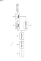
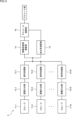
- FIG. 1 is a block diagram showing a schematic configuration example of a first embodiment of a measurement device to which the present technology is applied;
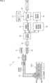
- FIG. 1 is a configuration diagram showing a configuration example of a measurement device according to a first embodiment.
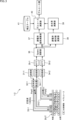
- FIG. 11 is a diagram showing a configuration example of a measurement device according to a second embodiment.
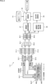
- FIG. 11 is a configuration diagram illustrating a measurement device according to a third embodiment.
- 11 is a block diagram showing a schematic configuration example of a second embodiment of a measurement device to which the present technology is applied.
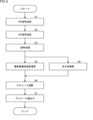
- FIG. 1 is a flowchart showing an example of a processing procedure of a measurement device to which the present technology is applied.
- FIG. 4 is a configuration diagram illustrating details of a dielectric spectroscopy section in the second embodiment of FIG. 3 .
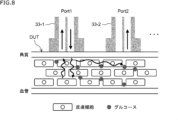
- FIG. 1 is a diagram showing a first example of probe arrangement.
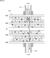
- FIG. 11 is a diagram showing a probe arrangement example 2.
- FIG. 13 is a diagram showing an embodiment in which probe arrangement example 1 is applied.
- FIG. 13 is a diagram showing an embodiment in which probe arrangement example 2 is applied.
- FIG. 2 is a diagram showing a specific example of the configuration of a dielectric spectroscopy section and a signal processing section of the measurement apparatus.
- FIG. 1 is a block diagram showing a schematic configuration example of a first embodiment of a measurement device to which the present technology is applied.
- measuring device 1 is a measuring device according to a first embodiment, and includes, for example, the configuration of a vector network analyzer (VNA).
- VNA vector network analyzer
- a vector network analyzer is a device that measures the S-parameters (Scattering Parameters) of an object to be measured.
- the measuring device 1 has a probe 11, a dielectric spectroscopy section 12, a signal processing section 13, a dielectric constant imaginary part calculation section 14, a water content calculation section 15, and a glucose calculation section 16.
- the probe 11 collectively represents the probes constituting one or more ports of the vector network analyzer.
- the probe 11 irradiates (injects) electromagnetic waves (hereinafter simply referred to as electromagnetic waves) in the microwave to millimeter wave band (e.g., 1 to 9 GHz) supplied from the dielectric spectroscopy section 12 onto the object to be measured, and also supplies (transmits) the electromagnetic waves reflected or transmitted (transmitted) by the object to be measured to the dielectric spectroscopy section 12.
- electromagnetic waves hereinafter simply referred to as electromagnetic waves
- the probe 11 may be composed of a coaxial probe, a waveguide, a microstrip line, a coplanar line, etc. as a transmission line for the electromagnetic waves.
- At least one of the probes 11 collectively represented constitutes a port (port 1) through which the electromagnetic waves are injected into the object to be measured.
- the probe of port 1 transmits the electromagnetic wave incident on the object under test (also called the incident signal), and transmits the electromagnetic wave reflected from the object under test (also called the reflected signal) to the dielectric spectroscopy section 12.
- the probes constituting ports other than port 1 transmit the electromagnetic wave (also called the transmitted signal) that is incident on the probe of port 1 and then transmitted (transmitted) through the object under test to the dielectric spectroscopy section 12.
- the dielectric spectroscopy unit 12 supplies the electromagnetic wave (incident signal) incident on the object to be measured to the probe 11, and receives the electromagnetic wave (reflected signal and transmitted signal) reflected and transmitted through the object to be measured via the probe 11.
- the dielectric spectroscopy unit 12 performs a conversion (Fourier transform) from a time domain representation to a frequency domain representation for each of the incident signal, reflected signal, and transmitted signal. As a result, it calculates frequency component signals that represent each of the incident signal, reflected signal, and transmitted signal in terms of frequency component values.
- the calculated frequency component signals of the incident signal, reflected signal, and transmitted signal are supplied to the signal processing unit 13.
- the signal processing unit 13 calculates the S parameters of the object to be measured based on the frequency component signals of the incident signal, the reflected signal, and the transmitted signal from the dielectric spectroscopy unit 12. For example, when using two ports of a vector network analyzer, S11 and S21 are calculated as S parameters. S11 represents the change in magnitude and phase of the reflected signal relative to the incident signal to the object to be measured. S21 represents the change in magnitude and phase of the transmitted signal relative to the incident signal to the object to be measured.
- the calculated S parameters are supplied to the dielectric constant imaginary part calculation unit 14 and the water content calculation unit 15. Note that the S parameters may be calculated based on the incident signal and the reflected signal among the incident signal, the reflected signal, and the transmitted signal.
- the value of the dielectric constant imaginary part and the water content of the object to be measured are calculated by calculating the S parameters of the object to be measured based on the frequency component signals of the incident signal, the reflected signal, and the transmitted signal (or the incident signal and the reflected signal) from the dielectric spectroscopy unit 12, but it is not necessary to calculate the S parameters.
- the value of the imaginary part of the dielectric constant and the water content of the object under measurement may be directly calculated based on the frequency component signals of the incident signal, the reflected signal, and the transmitted signal from the dielectric spectroscopy section 12.
- well-known methods such as the probe method and the S-parameter method are known as methods for calculating the complex dielectric constant of the object under measurement.
- the complex dielectric constant is calculated based on S11
- the complex dielectric constant is calculated based on S11 and S21. Either method may be used in the present technology. For example, when S11 and S21 are obtained as S-parameters, the complex dielectric constant may be calculated from S11 as in the probe method.
- the imaginary part of the dielectric constant calculation unit 14 calculates the value of the imaginary part (imaginary part of the dielectric constant) of the real and imaginary parts in the complex dielectric constant of the object being measured based on the S-parameters from the signal processing unit 13.
- the value of the imaginary part of the dielectric constant indicates frequency characteristics according to the concentration of glucose (grape sugar) contained in the object being measured.
- the calculated value of the imaginary part of the dielectric constant is supplied to the glucose calculation unit 16.
- the complex dielectric constant ⁇ * is expressed by the following equation (1).
- ⁇ * ⁇ '-j ⁇ ” (1)
- ⁇ ' is the real part of the complex dielectric constant
- ⁇ " is the imaginary part of the complex dielectric constant.
- the absolute value of the complex dielectric constant is the square root of the sum of the squares of the real and imaginary parts.
- the moisture content calculation unit 15 calculates the absolute value of the complex permittivity of the object to be measured (absolute permittivity value) based on the S-parameters from the signal processing unit 13, and calculates the moisture content of the object to be measured from the calibration curve of the absolute permittivity value and the volumetric moisture content, or the ratio of the absolute permittivity value and the relative permittivity of water.
- the moisture content of the object to be measured represents the moisture content in the material contained in the object to be measured.
- the calculated moisture content is supplied to the glucose calculation unit 16.
- the moisture content calculation unit 15 may calculate the value of the real part of the permittivity or the delay time of the reflected signal relative to the incident signal (the difference in reception time between the incident signal and the reflected signal), and calculate the moisture content based on the calibration curve of the real part of the permittivity and the volumetric moisture content, or the delay time of the reflected signal relative to the incident signal and the volumetric moisture content.
- the glucose calculation unit 16 calculates the glucose concentration (blood glucose level, glucose concentration in interstitial fluid) of the subject based on the value of the imaginary part of the dielectric constant from the imaginary part of the dielectric constant calculation unit 14 and the water content from the water content calculation unit 15.
- the glucose concentration is also called the glucose value.
- the unit of glucose concentration is the volume of glucose per unit volume.
- the frequency characteristics of the imaginary part of the dielectric constant differ when the water content differs even if the glucose concentration of the subject is the same. Therefore, the glucose calculation unit 16 corrects the glucose concentration estimated from the frequency characteristics of the imaginary part of the dielectric constant by a correction amount according to the actual water content, for example, assuming a default water content.
- the glucose calculation unit 16 determines the correction amount of the glucose concentration or the glucose concentration after correction using a correction table created in advance.
- the correction table is data that specifies the appropriate correction amount of the glucose concentration or the glucose concentration after correction for the glucose concentration estimated from the value (frequency characteristics) of the imaginary part of the dielectric constant and the actual water content from the water content calculation unit 15.
- the glucose concentration (glucose value) determined by the glucose calculation unit 16 is output to an arbitrary downstream processing unit.
- the downstream processing unit may be a display control unit that controls the display of the display unit, or a management unit that manages (saves, etc.) the data.
- the moisture content of the subject being measured can be calculated, and the glucose concentration can be corrected according to the moisture content, allowing an accurate glucose concentration to be calculated.
- the glucose concentration may be measured using a method other than that of the measuring device 1, such as infrared light or visible light, and the measurement result may be corrected based on the moisture content calculated by the measuring device 1.
- This technology can also be applied when measuring the concentration of a substance other than glucose (e.g., a substance in a living body) in the subject being measured.
- an accurate concentration can be measured taking the moisture content into account in the same way as when measuring the concentration of glucose.
- FIG. 2 is a configuration diagram showing an example of the configuration of a measuring device 1-1 which is a first embodiment of the measuring device 1.
- the measuring device 1-1 in FIG. 2 is a form in which only one port 1 of a vector network analyzer is used.
- the measuring device 1-1 in FIG. 2 has a transmitting unit 31, a directional coupling unit 32, a probe 33, a receiving unit 34, an FFT unit 35, an S parameter calculation unit 36, a dielectric constant imaginary part calculation unit 37, a dielectric constant absolute value calculation unit 38, a water content calculation unit 39, a glucose calculation unit 40, and a correction table 41.
- the transmitting unit 31, the directional coupling unit 32, the receiving unit 34, and the FFT unit 35 in FIG. 2 are components of the dielectric spectroscopy unit 12 in FIG. 1.
- the probe 33 in FIG. 2 is a component of the probe 11 in FIG. 1.
- the S parameter calculation unit 36 in FIG. 2 is a component of the signal processing unit 13 in FIG. 1.
- the permittivity imaginary part calculator 37 in Fig. 2 is a component of the permittivity imaginary part calculator 14 in Fig. 1.
- the permittivity absolute value calculator 38 and the water content calculator 39 in Fig. 2 are components of the water content calculator 15 in Fig. 1.
- the measurement target DUT is tissue around the part where the end (electrode) of the probe 33 is abutted, such as the earlobe, arm, palm, foot, or abdomen of a person (or animal). Note that, although keratin, skin cells, and blood vessels (blood) are shown as body tissues included in the measurement target DUT in Fig. 2, the measurement target DUT is not limited to these.
- the transmitter 31 supplies the electromagnetic wave (incident signal) incident on the DUT to be measured to the directional coupling unit 32.
- the electromagnetic wave (incident signal) is a signal of any fixed frequency, or a signal with a swept frequency.
- the directional coupling unit 32 splits the electromagnetic wave from the transmitter 31 and transmits it to the probe 33 and the receiver 34.
- the directional coupling unit 32 also transmits the electromagnetic wave from the probe 33 that has been reflected by the DUT to the receiver 34 (reflected signal).
- the probe 33 constitutes port 1 of the vector network analyzer.
- the probe 33 irradiates (inputs) the electromagnetic wave (incident signal) from the transmitter 31, which is supplied from the directional coupling unit 32, onto the DUT under test, and also transmits the electromagnetic wave (reflected signal) reflected by the DUT under test to the directional coupling unit 32.
- the receiver 34 receives the input signal from the transmitter 31 and the reflected signal from the directional coupling unit 32, and supplies them to the FFT unit 35.
- the FFT unit 35 performs FFT (fast Fourier transform) processing on the input signal from the receiving unit 34 and the reflected signal, converting them from a time domain representation to a frequency domain representation. As a result, the FFT unit 35 calculates the frequency component signals of the incident signal and the reflected signal, and supplies them to the S-parameter calculation unit 36.
- FFT fast Fourier transform
- the S-parameter calculation unit 36 calculates the S-parameters of the DUT under test based on the incident signal and reflected signal as frequency component signals from the FFT unit 35. In the measurement device 1-1, only the incident signal and reflected signal at port 1 are supplied to the S-parameter calculation unit 36, so S11 is calculated as the S-parameter. S11 represents the change in magnitude and phase of the reflected signal relative to the incident signal to the DUT under test.
- the S-parameters calculated by the S-parameter calculation unit 36 are supplied to the dielectric constant imaginary part calculation unit 37 and the dielectric constant absolute value calculation unit 38.
- the permittivity imaginary part calculation unit 37 calculates the value of the imaginary part (permittivity imaginary part) of the real and imaginary parts in the complex permittivity of the object to be measured based on the S parameters from the S parameter calculation unit 36.
- the value of the permittivity imaginary part indicates the frequency characteristics according to the concentration of glucose (grape sugar) contained in the object to be measured DUT.
- the calculated value of the permittivity imaginary part is supplied to the glucose calculation unit 40.
- the absolute dielectric constant calculation unit 38 calculates the absolute value of the complex dielectric constant (absolute dielectric constant) of the object to be measured based on the S parameters from the S parameter calculation unit 36.
- the absolute dielectric constant varies depending on the moisture content of the object to be measured DUT.
- the calculated absolute dielectric constant value is supplied to the moisture content calculation unit 39.
- the moisture content calculation unit 39 calculates the moisture content of the DUT to be measured based on the absolute dielectric constant value from the absolute dielectric constant calculation unit 38.
- the calculated moisture content is supplied to the glucose calculation unit 40.
- the glucose calculation unit 40 uses a correction table 41 to calculate the glucose concentration (glucose value) of the DUT to be measured, based on the value of the imaginary part of the dielectric constant from the imaginary part of the dielectric constant calculation unit 37 and the moisture content from the moisture content calculation unit 39. That is, the glucose calculation unit 40 determines, using the correction table 41, a correction amount corresponding to the glucose concentration estimated from the value of the imaginary part of the dielectric constant (frequency characteristics) and the moisture content from the moisture content calculation unit 39, and adds the determined correction amount to the glucose concentration estimated from the value of the imaginary part of the dielectric constant.
- the glucose value calculated by the glucose calculation unit 40 is output to any processing unit at a subsequent stage.
- the measuring device 1-1 can measure the glucose concentration by the so-called probe method, and can accurately calculate the glucose concentration based on the water content.
- Fig. 3 is a configuration diagram showing an example of the configuration of a measurement device 1-2 which is Example 2 of the measurement device 1.
- the measurement device 1-2 in Fig. 3 is configured to use two ports, port 1 and port 2, of a vector network analyzer.
- parts corresponding to those of the measurement device 1-1 in Fig. 2 are given the same reference numerals, and their explanation will be omitted as appropriate.
- the measuring device 1-2 in FIG. 3 has a transmitter 31-1, a directional coupling unit 32-1, probes 33-1 and 33-2, receivers 34-1 and 34-2, FFT units 35-1 and 35-2, an S parameter calculator 36, an imaginary part of dielectric constant calculator 37, an absolute value of dielectric constant calculator 38, a water content calculator 39, a glucose calculator 40, and a correction table 41.
- the transmitter 31-1, the directional coupling unit 32-1, the receivers 34-1 and 34-2, and the FFT units 35-1 and 35-2 in FIG. 3 are components of the dielectric spectroscopy unit 12 in FIG. 1.
- the probes 33-1 and 33-2 in FIG. 3 are components of the probe 11 in FIG. 1.
- the DUT to be measured is the same as the DUT to be measured in FIG. 2.
- the transmitter 31-1, directional coupling unit 32-1, probe 33-1, receiver 34-1, and FFT unit 35-1 are the same as the transmitter 31, directional coupling unit 32, probe 33-1, receiver 34, and FFT unit 35 in FIG. 2, so their explanations are omitted.
- Probe 33-2 constitutes port 2 of the vector network analyzer. Probe 33-2 transmits the electromagnetic waves (transmitted signals) from transmitter 31-1 that have passed through (transmitted) the DUT to be measured to receiver 34-2.
- the receiver 34-2 receives the transmitted signal from the probe 33-2 and supplies it to the FFT unit 35-2.
- the FFT unit 35-2 performs FFT (fast Fourier transform) processing on the transmitted signal from the receiving unit 34-2 to convert it from a time domain representation to a frequency domain representation. As a result, the FFT unit 35-2 calculates the frequency component signals of the transmitted signal and supplies them to the S-parameter calculation unit 36.
- FFT fast Fourier transform
- the S-parameter calculation unit 36 calculates the S-parameters of the DUT under test based on the incident signal and reflected signal as frequency component signals from the FFT unit 35-1 and the transmitted signal as frequency component signals from the FFT unit 35-1.
- the incident signal and reflected signal at port 1 and the transmitted signal at port 2 are supplied to the S-parameter calculation unit 36, so S-parameters S11 and S21 are calculated.
- S11 represents the change in magnitude and phase of the reflected signal relative to the incident signal to the DUT under test.
- S21 represents the change in magnitude and phase of the transmitted signal relative to the incident signal to the DUT under test.
- the S-parameters calculated by the S-parameter calculation unit 36 are supplied to the dielectric constant imaginary part calculation unit 37 and the dielectric constant absolute value calculation unit 38.
- the permittivity imaginary part calculation unit 37 calculates the value of the imaginary part (permittivity imaginary part) of the real and imaginary parts in the complex permittivity of the object to be measured based on the S parameters from the S parameter calculation unit 36. Note that since the measuring device 1-2 can calculate the complex permittivity based on the S parameters S11 and S21, the value of the permittivity imaginary part is also calculated based on S11 and S21. The calculated value of the permittivity imaginary part is supplied to the glucose calculation unit 40.
- the dielectric constant absolute value calculation unit 38 calculates the absolute value of the complex dielectric constant (dielectric constant absolute value) of the object to be measured based on the S parameters from the S parameter calculation unit 36.
- the dielectric constant absolute value is also calculated based on S11 and S21.
- the calculated dielectric constant absolute value is supplied to the moisture content calculation unit 39.
- the moisture content calculation unit 39 calculates the moisture content of the DUT to be measured based on the absolute dielectric constant value from the absolute dielectric constant calculation unit 38.
- the calculated moisture content is supplied to the glucose calculation unit 40.
- the glucose calculation unit 40 uses a correction table 41 to calculate the glucose concentration (glucose value) of the DUT to be measured based on the value of the imaginary part of the dielectric constant from the imaginary part of the dielectric constant calculation unit 37 and the moisture content from the moisture content calculation unit 39.
- the calculated glucose value is output to an arbitrary processing unit in a subsequent stage.
- the measuring device 1-2 can measure the glucose concentration using the so-called S-parameter method, and can accurately calculate the glucose concentration based on the water content.
- the measuring device 1-2 may also calculate the glucose concentration using the probe method.
- Fig. 4 is a configuration diagram showing an example of the configuration of a measurement device 1-3 which is Example 3 of the measurement device 1.
- the measurement device 1-3 in Fig. 4 is configured to use two ports 1 and 2 of a vector network analyzer, and is configured to allow electromagnetic waves to be input from both ports 1 and 2 in a time-division manner.
- parts corresponding to those of the measurement device 1-2 in Fig. 3 are given the same reference numerals, and their explanation will be omitted as appropriate.
- the measuring device 1-3 in FIG. 4 has transmitters 31-1 and 31-2, directional coupling units 32-1, probes 33-1 and 33-2, receivers 34-1 and 34-2, FFT units 35-1 and 35-2, S parameter calculation units 36-1 and 36-2, imaginary part of dielectric constant calculation unit 37, absolute value of dielectric constant calculation unit 38, water content calculation unit 39, glucose calculation unit 40, and a correction table 41.
- the transmitters 31-1 and 31-2, directional coupling units 32-1 and 32-2, receivers 34-1 and 34-2, and FFT units 35-1 and 35-2 in FIG. 4 are components of the dielectric spectroscopy unit 12 in FIG. 1.
- the probes 33-1 and 33-2 in FIG. 4 are components of the probe 11 in FIG. 1.
- the S parameter calculation units 36-1 and 36-2 are components of the signal processing unit 13 in FIG. 1.
- the dielectric constant imaginary part calculation unit 37 in FIG. 4 is a component of the dielectric constant imaginary part calculation unit 14 in FIG. 1.
- the dielectric constant absolute value calculation unit 38 and the moisture content calculation unit 39 in FIG. 4 are components of the moisture content calculation unit 15 in FIG. 1.
- the glucose calculation unit 40 and the correction table 41 in FIG. 4 are components of the glucose calculation unit 16 in FIG. 1.
- the DUT under test is the same as the DUT under test in FIG. 3.
- the transmitter 31-1, directional coupling unit 32-1, probe 33-1, receiver 34-1, and FFT unit 35-1 are the same as the transmitter 31-1, directional coupling unit 32-1, probe 33-1, receiver 34-1, and FFT unit 35-1 in FIG. 3, so the description will be omitted.
- the transmitter 31-2, directional coupling unit 32-2, probe 33-2, receiver 34-2, and FFT unit 35-2 in FIG. 4 are the same as the transmitter 31-1, directional coupling unit 32-1, probe 33-1, receiver 34-1, and FFT unit 35-1 in FIG. 3, so a description thereof will be omitted.
- the probe 33-2, receiver 34-2, and FFT section 35-2 act as components for the transmitted signal, similar to the probe 33-2, receiver 34-2, and FFT section 35-2 in FIG. 3.
- the probe 33-1, receiver 34-1, and FFT section 35-1 act as components for the transmitted signal, similar to the probe 33-2, receiver 34-2, and FFT section 35-2 in FIG. 3.
- Directional coupling units 32-1 and 32-2 act as directional coupling units that branch the incident signal from transmitters 31-1 and 31-2 and the reflected signal or transmitted signal from the DUT under test, respectively, and supply them to receivers 34-1 and 34-2.
- FFT unit 35-1 calculates the frequency component signals of the incident signal supplied from transmitter 31-1 to the DUT under test via probe 33-1 of port 1, the reflected signal supplied from the incident signal via probe 33-1, and the transmitted signal supplied from transmitter 31-2 to the DUT under test via probe 33-2 of port 2 via probe 33-1 of port 1, respectively, and supplies them to S-parameter calculation unit 36-1.
- the FFT unit 35-2 calculates the frequency component signals of the incident signal supplied from the transmitter 31-2 to the DUT under test via the probe 33-2 of port 2, the reflected signal supplied from the incident signal via the probe 33-2, and the transmitted signal supplied from the transmitter 31-1 to the DUT under test via the probe 33-1 of port 1 via the probe 33-2 of port 2, and supplies these signals to the S-parameter calculation unit 36-2.
- the S-parameter calculation unit 36-1 calculates the S-parameters of the DUT under test based on the incident signal, reflected signal, and transmitted signal as frequency component signals from the FFT unit 35-1. In the measurement device 1-3, the S-parameter calculation unit 36-1 calculates S-parameters S11 and S12 by using the reflected signal from the DUT under test at port 1 and the transmitted signal from port 2 to port 1. The S-parameters calculated by the S-parameter calculation unit 36-1 are supplied to the dielectric constant imaginary part calculation unit 37 and the dielectric constant absolute value calculation unit 38.
- the S-parameter calculation unit 36-2 calculates the S-parameters of the DUT under test based on the incident signal, reflected signal, and transmitted signal as frequency component signals from the FFT unit 35-2. In the measurement device 1-3, the S-parameter calculation unit 36-2 calculates S-parameters S22 and S21 using the reflected signal from the DUT under test at port 2 and the transmitted signal from port 1 to port 2. If S11 and S21 represent the change in magnitude and phase of the reflected signal and transmitted signal relative to the incident signal from port 1 to the DUT under test, S22 and S12 represent the change in magnitude and phase of the reflected signal and transmitted signal relative to the incident signal from port 2 to the DUT under test. S22 and S12 correspond to S11 and S21 when the contact positions of the probe 33-1 of port 1 and the probe 33-2 of port 2 on the DUT under test are swapped.
- the imaginary part of the dielectric constant calculation unit 37 calculates the value of the imaginary part (dielectric constant imaginary part) of the real part and imaginary part of the complex dielectric constant of the object to be measured based on the S parameters from the S parameter calculation unit 36-1 and the S parameter calculation unit 36-2, and supplies it to the glucose calculation unit 40.
- the complex dielectric constant can be calculated based on only S11, only S22, S11 and S21, or S22 and S12, which are S parameters from the S parameter calculation unit 36-1 and the S parameter calculation unit 36-2.
- the imaginary part of the dielectric constant calculation unit 37 may supply the value of the imaginary part of the dielectric constant calculated based on any one or more of these only S11, only S22, S11 and S21, or S22 and S12, to the glucose calculation unit 40, or may supply a value (e.g., an average value) obtained by integrating the values of the imaginary parts of the dielectric constant to the glucose calculation unit 40.
- the value of the imaginary part of the dielectric constant may be calculated by combining the values obtained from S11 and S22 (e.g., the average), or by combining the values obtained from S11 and S21, and from S22 and S12 (e.g., the average).
- the absolute dielectric constant calculation unit 38 calculates the absolute value of the complex dielectric constant of the object to be measured (absolute dielectric constant value) based on the S parameters from the S parameter calculation unit 36-1 and the S parameter calculation unit 36-2, and supplies it to the moisture content calculation unit 39.
- the absolute dielectric constant calculation unit 38 can calculate the absolute dielectric constant value from multiple combinations of S parameters, similar to the imaginary part of dielectric constant calculation unit 37.
- the absolute dielectric constant calculation unit 38 may, for example, supply the absolute dielectric constant value calculated based on S11 and S21 and the absolute dielectric constant value calculated based on S21 and S12 to the moisture content calculation unit 39, respectively, or may supply the moisture content calculation unit 39 with a value obtained by integrating these absolute dielectric constant values (for example, the average value).
- the absolute dielectric constant value may be integrated by calculating the absolute dielectric constant value by integrating the value obtained by integrating S11 and S22 (for example, the average value) as S11 and the value obtained by integrating S21 and S12 (for example, the average value) as S21.
- the moisture content calculation unit 39 calculates the moisture content of the DUT to be measured based on the absolute dielectric constant value from the absolute dielectric constant calculation unit 38, and supplies it to the glucose calculation unit 40.
- the moisture content calculation unit 39 may supply the moisture content calculated based on these absolute dielectric constant values to the glucose calculation unit 40, or it may supply an integrated value of these moisture contents (e.g., an average value) to the glucose calculation unit 40.
- the glucose calculation unit 40 uses a correction table 41 to calculate the glucose concentration (glucose value) of the DUT to be measured based on the value of the imaginary part of the dielectric constant from the imaginary part of the dielectric constant calculation unit 37 and the moisture content from the moisture content calculation unit 39, and outputs it to any processing unit in the subsequent stage.
- the glucose calculation unit 40 is supplied with the value of the imaginary part of the dielectric constant calculated based on S11 and S21 and the value of the imaginary part of the dielectric constant calculated based on S22 and S12, it may integrate (average) the glucose values calculated based on each imaginary part of the dielectric constant.
- the glucose calculation unit 40 When the glucose calculation unit 40 is supplied with the moisture content calculated based on the absolute value of the dielectric constant based on S11 and S21 and the moisture content calculated based on the absolute value of the dielectric constant based on S22 and S12, it may integrate (average) the glucose values calculated based on each moisture content.
- the measuring device 1-3 can measure the glucose concentration using the so-called S-parameter method, and can accurately calculate the glucose concentration based on the water content.
- the measuring device 1-2 may also calculate the glucose concentration using the probe method.
- FIG. 5 is a block diagram showing a schematic configuration example of a second embodiment of a measuring device to which the present technology is applied.
- the same reference numerals are used to designate parts common to the measuring device 1 in Fig. 1, and description thereof will be omitted.
- the measurement device 2 according to the second embodiment of FIG. 5 has the dielectric spectroscopy section 12 and signal processing section 13 of FIG. 1 provided for each of the N (N is a natural number equal to or greater than 2) probes 11-1 to 11-N (N is a natural number equal to or greater than 2) included in the probe 11 (for each of the N ports).
- the dielectric spectroscopy sections 12-1 through 12-N and the signal processing sections 13-1 through 13-N perform processing equivalent to that of the dielectric spectroscopy section 12 and the signal processing section 13 when one probe is used as the probe 11 in the measurement device 1 of FIG. 1.
- Example 3 of the measurement device 1 of FIG. 4 corresponds to the form of the measurement device 2 of FIG. 5 when N is 2.
- FIG. 6 is a flowchart showing an example of a processing procedure of a measurement device (measurement device 1 of FIG. 1) to which the present technology is applied.
- the dielectric spectroscopy unit 12 transmits an RF signal (incident signal) to the object to be measured via the probe 11.
- the dielectric spectroscopy unit 12 receives an RF signal (incident signal, reflected signal). Note that, when two probes (ports) are used, a transmitted signal may be received.
- the dielectric spectroscopy unit 12 and the signal processing unit 13 perform signal processing on the received RF signal.
- the S parameters of the object to be measured are calculated and supplied to the dielectric constant imaginary part calculation unit 14 and the water content calculation unit 15.
- step S4 the permittivity imaginary part calculation unit 14 calculates the value (frequency characteristic) of the imaginary part of the complex permittivity (permittivity imaginary part) based on the S parameters calculated in step S3.
- step S5 the moisture content calculation unit 15 calculates the absolute value of the complex permittivity (permittivity absolute value) based on the S parameters calculated in step S3.
- step S6 the glucose calculation unit 16 calculates the glucose value based on the value of the permittivity imaginary part calculated in step S4 and the moisture content calculated in step S5. That is, the glucose calculation unit 16 corrects the glucose value calculated from the value of the permittivity imaginary part by a correction amount according to the moisture content.
- step S7 the glucose calculation unit 16 outputs the calculated glucose value to a downstream processing unit. The above processes of steps S1 to S7 are repeated.
- Fig. 7 is a configuration diagram illustrating details of the dielectric spectroscopy section 12 in the measurement apparatus 1-2 according to Example 2 in Fig. 3. Note that Fig. 7 shows the configuration of a processing section preceding the FFT sections 35-1 and 35-2 in Fig. 3.
- the measuring device 1-2 has two probes 33-1 and 33-2 that constitute ports 1 and 2, similar to Fig. 3.
- the measuring device 1-2 has a PLL circuit 61, mixers 62, 67-1, 69-1, 69-2, attenuator 63, directional coupling section 64, and LNAs (Low Noise Amplifiers) 66-1, 68-1, 68-2 as components of the dielectric spectroscopy section 12.
- the PLL circuit 61 generates a high-frequency reference clock, generates an LO signal (local oscillator frequency signal), and supplies it to the mixers 62, 67-1, 69-1, 69-2.
- the mixer 62 performs frequency conversion by mixing an IF (Intermediate Frequency) signal with the LO signal, and generates an RF signal that becomes the input signal for the DUT under test.
- the RF signal has a higher frequency than the IF signal and the LO signal.
- the RF signal generated by mixer 62 is supplied to attenuator 63.
- the attenuator 63 attenuates the intensity (amplitude) of the RF signal from the mixer 62 and supplies it to the directional coupling unit 64.
- the directional coupling unit 64 branches the RF signal from the attenuator 63, supplying one RF signal to the probe 33-1 of port 1 and the other RF signal to the LNA 66-1.
- the probe 33-1 also supplies the RF signal that is the incident signal reflected by the DUT under test as a reflected signal to the LNA 68-1.
- the RF signal that is incident on the DUT under test from the probe 33-1 as an incident signal and transmitted to the probe 33-2 of port 2 is supplied to the LNA 68-2 as a transmitted signal.
- LNA 66-1 supplies the RF signal received as an incident signal to mixer 67-1.
- LNA 68-1 supplies the RF signal received as a reflected signal to mixer 69-1.
- LNA 68-2 supplies the RF signal received as a transmitted signal to mixer 69-2.
- Mixer 67-1 converts the RF signal, which is the incident signal from LNA 66-1, to the frequency of the IF signal by mixing it with the LO signal from the PLL circuit 61.
- Mixer 69-1 converts the RF signal, which is the reflected signal from LNA 68-1, to the frequency of the IF signal by mixing it with the LO signal from the PLL circuit 61.
- Mixer 69-2 converts the RF signal, which is the transmitted signal from LNA 68-2, to the frequency of the IF signal by mixing it with the LO signal from the PLL circuit 61.
- the incident signal, reflected signal, and transmitted signal converted to IF signals by these mixers 67-1, 69-1, and 69-2 are supplied to the FFT units 35-1 and 35-2 in FIG. 3.
- measurement device 7 can also be applied to measurement devices of different forms from the measurement device 1-2 according to the embodiment 2 in FIG. 3, such as the measurement device 1-1 according to the embodiment 1 in FIG. 2, the measurement device 1-3 according to the embodiment 3 in FIG. 4, and the measurement device 2 according to the second embodiment in FIG. 5.
- FIG. 8 is a diagram showing a probe arrangement example 1.
- the probes 33-1 and 33-2 represent, for example, the probes 33-1 and 33-2 of the ports 1 and 2 shown in FIG. 3.
- the probes 33-1 and 33-2 are arranged so that the contact surfaces of the ends (electrodes) of the probes against the DUT to be measured are positioned along a plane. Even if the number of probes is any number other than two (multiple), the ends (electrodes) of the probes can be arranged in positions along a plane.
- a plurality of electrodes including at least one of an electrode of a probe that inputs an incident signal to the DUT to be measured and acquires a reflected signal and an electrode of a probe that acquires a transmitted signal, are arranged in positions along a plane.
- the length of the transmission line of the RF signal transmitted through each probe (port) can be made common, so that correction of the delay caused by the difference in the length of the transmission line is not required.
- FIG. 9 is a diagram showing a probe arrangement example 2.
- the probes 33-1 and 33-2 represent, for example, the probes 33-1 and 33-2 of the ports 1 and 2 shown in FIG. 3.
- the probes 33-1 and 33-2 are arranged so that the contact surfaces of the ends (electrodes) of the probes against the DUT to be measured are in opposing positions. Even if the number of probes is any number other than two (multiple), the ends (electrodes) of the probes can be arranged in opposing positions across the DUT.
- a signal is input to the DUT to be measured, and multiple electrodes including at least one of an electrode of a probe that acquires a reflected signal and an electrode of a probe that acquires a transmitted signal are arranged in opposing positions.
- the DUT to be measured is a finger or an arm
- the glucose level is measured not only in the skin cells and blood vessels (blood) near the surface of the skin but also in the range where bones are present.
- the probe electrodes are arranged opposite each other as in this example, by making the lengths of the transmission lines for the RF signals transmitted through each probe (port) the same (equal), it is possible to eliminate the need to compensate for delays that arise due to differences in the lengths of the transmission lines.
- FIG. 10 is a diagram showing an embodiment in which the probe arrangement example 1 is applied.
- a smart watch 91 is attached to a wrist using a band.
- the body of the smart watch 91 is equipped with the dielectric spectroscopy unit 12 and the signal processing unit 13 of the measuring device 1 shown in FIG. 1 and the like.
- the smart watch 91 is an example of a device in which a device body equipped with a processing unit is attached to a measured object by a wearing tool such as a band, and is not limited to a specific type of device.
- a plurality of electrodes 92 of a plurality of probes of the measuring device 1 are arranged at positions along the plane of the inner surface of the band (the surface that contacts the wrist).
- a plurality of electrodes 92 are arranged at positions facing the main body equipped with the dielectric spectroscopy unit 12 and the signal processing unit 13. This allows the length of the transmission line of the RF signal transmitted to each probe to be common.
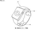
- Fig. 11 is a diagram showing an embodiment in which the probe arrangement example 1 is applied.
- the smart watch 91 is the same as that in Fig. 10.
- two electrodes 93 and 94 of two probes of the measuring device 1 are arranged at opposing positions on the inner surface of the band (the surface that contacts the wrist).
- the electrodes 93 and 94 are arranged at positions where the distance is transparent to the main body of the smart watch 91. This allows the length of the transmission line of the RF signal transmitted through each probe to be common.
- Fig. 12 is a diagram showing a specific example of the configuration of the circuit (dielectric spectroscopy section 12 and signal processing section 13) up to the calculation of S-parameters in the measurement device 1 in Fig. 1.
- the measurement device 1 in Fig. 12 shows a form using a probe 33 of one port 1 like the measurement device 1-1 according to the embodiment 1 in Fig. 2, and in the figure, the same reference numerals are given to the parts in common with Fig. 2, and the description thereof will be omitted. Also, some blocks in Fig. 2 are omitted.
- the circuit section 111 shows a part of the circuit arranged in the dielectric spectroscopy section 12 and the signal processing section 13, and has an RF circuit 121, an ACD (Analog to Digital Converter) 122, an FFT section 123, and an S-parameter calculation section 124.
- ACD Analog to Digital Converter
- the RF circuit 121 generates and outputs an RF signal at the frequency of the electromagnetic wave that is the incident signal that is incident on the DUT under test, and also receives the RF signals that are the incident signal and the reflected signal, and performs frequency conversion to an IF signal.
- the incident signal and the reflected signal that are received by the RF circuit 121 and frequency converted to an IF signal are supplied to the ADC 122.
- the ADC 122 samples the incident signal and reflected signal from the RF circuit 121 at a predetermined sampling period, converts them into digital data, and then supplies them to the FFT unit 123.
- the FFT unit 123 performs FFT processing on the incident signal and reflected signal converted into digital data by the ADC 122, and converts the incident signal and reflected signal from a time domain representation to a frequency domain representation.
- the FFT unit 123 calculates S parameters based on the incident signal and reflected signal converted into a frequency domain representation, and supplies them to the subsequent dielectric constant imaginary part calculation unit 37.
- All or part of the RF circuit 121, ACD 122, FFT section 123, and S parameter calculation section 124 of the circuit section 111 can be implemented on the same substrate or on a single chip.
- the configuration of the circuit section 111 in FIG. 12 can be applied to measurement devices other than those used to measure glucose concentration.
- a measuring device comprising: a processing unit that calculates a glucose concentration of the object to be measured based on a value of an imaginary part of the complex dielectric constant of the object to be measured and a water content of the object to be measured.
- the measurement device according to claim 1 , wherein the processing unit calculates the glucose concentration of the subject based on a value of an imaginary part of the complex dielectric constant and a water content of the subject.
- the processing unit calculates the moisture content based on at least an incident signal as an electromagnetic wave incident on the object to be measured, a reflected signal of the incident signal reflected by the object to be measured, and a transmitted signal of the incident signal transmitted through the object to be measured.
- the processing unit calculates an absolute value or a real part of the complex dielectric constant based on at least the incident signal and the reflected signal among the incident signal, the reflected signal, and the transmitted signal, and calculates the water content based on the absolute value or the real part of the complex dielectric constant.
- the processing unit calculates an S parameter based on at least the incident signal and the reflected signal among the incident signal, the reflected signal, and the transmitted signal, and calculates an absolute value or a real part of the complex dielectric constant based on the S parameter.
- the measurement device according to (4) or (5).
- the processing unit calculates the complex dielectric constant based on at least an incident signal as an electromagnetic wave incident on the object under test, a reflected signal of the incident signal reflected from the object under test, and a transmitted signal of the incident signal transmitted through the object under test.
- the processing unit calculates an S parameter based on at least the incident signal and the reflected signal among the incident signal, the reflected signal, and the transmitted signal, and calculates a value of an imaginary part of the complex dielectric constant based on the S parameter.
- the measurement device described in (7). (9) a first electrode that applies the incident signal to the object to be measured and acquires the reflected signal, and a second electrode that acquires the transmitted signal;
- the measuring device according to any one of (3) to (8), wherein a plurality of electrodes including at least one of the first electrode and the second electrode are arranged at positions along a plane.
- (10) a first electrode that applies the incident signal to the object to be measured and acquires the reflected signal, and a second electrode that acquires the transmitted signal;
- the measuring device according to any one of (3) to (8), wherein a plurality of electrodes including at least one of the first electrode and the second electrode are arranged opposite to each other with the object to be measured therebetween.
- (11) a PLL circuit for generating an LO signal which is mixed with an IF signal to generate the incident signal;
- the measurement device according to any one of (3) to (10), wherein an LO signal that is mixed with the reflected signal or the transmitted signal to generate the IF signal is generated by the PLL circuit.
- a measuring method comprising: a processing unit of a measuring device, the processing unit calculating a glucose concentration of the object to be measured based on the complex dielectric constant of the object to be measured and the water content of the object to be measured.
- an RF circuit that generates an incident signal as an electromagnetic wave incident on an object under test and receives the incident signal and a reflected signal that is a reflection of the incident signal from the object under test; an analog-to-digital converter for converting the incident signal and the reflected signal received by the RF circuit into digital data; a conversion unit that performs a Fourier transform on the incident signal and the reflected signal that have been converted into digital data by the AD converter; an S parameter calculation unit that calculates S parameters based on the incident signal and the reflected signal that have been Fourier transformed by the conversion unit.
- An RF circuit; An AD converter, A conversion unit; an S-parameter calculation unit; the RF circuit of the measurement device generates an incident signal as an electromagnetic wave incident on an object under test, receives the incident signal and a reflected signal that is a reflection of the incident signal from the object under test,
- the AD converter converts the incident signal and the reflected signal into digital data;
- the conversion unit performs a Fourier transform on the incident signal and the reflected signal that have been converted into the digital data;
- the S parameter calculation unit calculates an S parameter based on the Fourier transformed incident signal and the reflected signal.
Landscapes
- Physics & Mathematics (AREA)
- Electromagnetism (AREA)
- Health & Medical Sciences (AREA)
- Life Sciences & Earth Sciences (AREA)
- Chemical & Material Sciences (AREA)
- Analytical Chemistry (AREA)
- Biochemistry (AREA)
- General Health & Medical Sciences (AREA)
- General Physics & Mathematics (AREA)
- Immunology (AREA)
- Pathology (AREA)
- Measurement Of The Respiration, Hearing Ability, Form, And Blood Characteristics Of Living Organisms (AREA)
Abstract
本技術は、被測定対象に含まれるグルコース(ブドウ糖)の濃度を正確に測定できるようにする測定装置、及び、測定方法に関する。 被測定対象の複素誘電率と、被測定対象の含水率とに基づいて、被測定対象のグルコース濃度が算出される。含水率は、被測定対象に入射した電磁波としての入射信号と、入射信号に対して被測定対象を反射した反射信号とに基づいて算出され得る。
Description
本技術は、測定装置、及び、測定方法に関し、特に、被測定対象に含まれるグルコース(ブドウ糖)の濃度を正確に測定できるようにした測定装置、及び、測定方法に関する。
非侵襲の血糖値センサに関して、赤外線レーザやマイクロ波及びミリ波を用いたセンサが製品化及び研究されている。現状の非侵襲の血糖値センサに使われている技術では、体内や体外(汗など)のバルク水の割合により精度が落ちるという課題がある。特許文献1には、誘電分光を用いて成分濃度の測定をする際の被測定対象の含水率による影響を抑制し、高精度に成分濃度を測定する技術が開示されている。
特許文献1では、複素誘電率スペクトルに対する被測定対象の含水率の影響を複素誘電率スペクトルの規格化という処理により低減することで、測定結果である成分濃度に対する被測定対象の含水率の影響を低減している。しかしながら、複素誘電率スペクトルの規格化だけでは、複素誘電率スペクトルに対する被測定対象の含水率の影響を十分に低減することは難しい。
本技術はこのような状況に鑑みてなされたものであり、被測定対象に含まれるグルコース(ブドウ糖)の濃度を正確に測定できるようにする。
本技術の第1の側面の測定装置は、被測定対象の複素誘電率と、前記被測定対象の含水率とに基づいて、前記被測定対象のグルコース濃度を算出する処理部を有する測定装置である。
本技術の第1の側面の測定方法は、処理部を有する測定装置の前記処理部が、被測定対象の複素誘電率と、前記被測定対象の含水率とに基づいて、前記被測定対象のグルコース濃度を算出する測定方法である。
本技術の第1の側面の測定装置及び測定方法においては、被測定対象の複素誘電率と、前記被測定対象の含水率とに基づいて、前記被測定対象のグルコース濃度が算出される。
本技術の第2の側面の測定装置は、被測定対象に入射する電磁波としての入射信号を生成し、前記入射信号と、前記入射信号に対して前記被測定対象を反射した反射信号とを受信するRF回路と、前記RF回路により受信された前記入射信号及び前記反射信号をデジタルデータに変換するADコンバータと、前記ADコンバータによりデジタルデータに変換された前記入射信号及び前記反射信号をフーリエ変換する変換部と、前記変換部によりフーリエ変換された前記入射信号及び前記反射信号とに基づいてSパラメータ(Scattering parameters)を算出するSパラメータ演算部とを有する測定装置である。
本技術の第2の側面の測定方法は、RF回路と、ADコンバータと、変換部と、Sパラメータ演算部とを有する測定装置の前記RF回路が、被測定対象に入射する電磁波としての入射信号を生成し、前記入射信号と、前記入射信号に対して前記被測定対象を反射した反射信号とを受信し、前記ADコンバータが、前記入射信号及び前記反射信号をデジタルデータに変換し、前記変換部が、前記デジタルデータに変換された前記入射信号及び前記反射信号をフーリエ変換し、前記Sパラメータ演算部が、前記フーリエ変換された前記入射信号及び前記反射信号とに基づいてSパラメータを算出する測定方法である。
本技術の第2の側面の測定装置及び測定方法においては、被測定対象に入射する電磁波としての入射信号が生成され、前記入射信号と、前記入射信号に対して前記被測定対象を反射した反射信号とが受信され、前記入射信号及び前記反射信号がデジタルデータに変換され、前記デジタルデータに変換された前記入射信号及び前記反射信号がフーリエ変換され、前記フーリエ変換された前記入射信号及び前記反射信号とに基づいてSパラメータが算出される。
以下、図面を参照しながら本技術の実施の形態について説明する。
<<本技術が適用された測定装置の第1の実施の形態>>
図1は、本技術が適用された測定装置の第1の実施の形態の概略構成例を示したブロック図である。
図1は、本技術が適用された測定装置の第1の実施の形態の概略構成例を示したブロック図である。
図1において、測定装置1は、第1の実施の形態に係る測定装置であり、例えば、ベクトルネットワークアナライザ(VNA:Vector Network Analyzer)の構成を含む。ベクトルネットワークアナライザは、周知のように被測定対象のSパラメータ(Scattering Parameter)を測定する装置である。
測定装置1は、プローブ11、誘電分光部12、信号処理部13、誘電率虚部演算部14、含水率演算部15、及び、グルコース演算部16を有する。プローブ11は、ベクトルネットワークアナライザの1又は複数のポートのそれぞれを構成するプローブを包括して表す。プローブ11は、誘電分光部12から供給されたマイクロ波乃至ミリ波帯(例えば、1乃至9GHz)の電磁波(以下、単に電磁波という)を被測定対象に照射(入射)し、また、被測定対象を反射又は透過(伝送)した電磁波を誘電分光部12に供給(伝送)する。プローブ11は、電磁波の伝送線として同軸プローブ、導波管、マイクロストリップ線路、コプレーナ線路等で構成されていてよい。なお、包括して表されたプローブ11のうちの少なくとも1つのプローブは、被測定対象に対して電磁波を入射するポート(ポート1)を構成する。ポート1のプローブは、被測定対象に入射する電磁波(入射信号ともいう)を伝送し、かつ、被測定対象を反射した電磁波(反射信号ともいう)を誘電分光部12に伝送する。ポート1以外のポートを構成するプローブは、ポート1のプローブから入射した後に被測定対象を透過(伝送)した電磁波(透過信号ともいう)を誘電分光部12に伝送する。
誘電分光部12は、被測定対象に入射する電磁波(入射信号)をプローブ11に供給し、被測定対象を反射及び透過した電磁波(反射信号及び透過信号)をプローブ11を介して受信する。誘電分光部12は、入射信号、反射信号、及び、透過信号のそれぞれに対して、時間領域表現から周波数領域表現への変換(フーリエ変換)を行う。その結果、入射信号、反射信号、及び、透過信号のそれぞれを周波数成分値で表した周波数成分信号を算出する。算出された入射信号、反射信号、及び、透過信号の周波数成分信号は、信号処理部13に供給される。
信号処理部13は、誘電分光部12からの入射信号、反射信号、及び、透過信号のそれぞれの周波数成分信号に基づいて、被測定対象のSパラメータを算出する。例えば、ベクトルネットワークアナライザの2ポートを使用する場合、SパラメータとしてS11とS21とが算出される。S11は、被測定対象への入射信号に対する反射信号の大きさと位相の変化を表す。S21は、被測定対象への入射信号に対する透過信号の大きさと位相の変化を表す。算出されたSパラメータは、誘電率虚部演算部14と含水率演算部15とに供給される。なお、Sパラメータは、入射信号、反射信号、及び、透過信号のうちの入射信号及び反射信号に基づいて算出される場合であってもよい。また、本技術において、誘電分光部12からの入射信号、反射信号、及び、透過信号(又は、入射信号及び反射信号)のそれぞれの周波数成分信号に基づいて、被測定対象のSパラメータを算出することで、被測定対象の誘電率虚部の値と含水率とを算出するが、Sパラメータを必ずしも算出する必要はない。例えば、誘電分光部12からの入射信号、反射信号、及び、透過信号のそれぞれの周波数成分信号に基づいて、被測定対象の誘電率虚部の値と含水率とを直接的に算出してもよい。また、被測定対象の複素誘電率を算出する方法として、プローブ法やSパラメータ法などの周知の方法が知られており、プローブ法では、S11に基づいて複素誘電率が算出され、Sパラメータ法ではS11とS21とに基づいて複素誘電率が算出される。本技術ではいずれの方法が用いられる場合であってもよい。例えば、SパラメータとしてS11とS21とが得られる場合にプローブ法のようにS11から複素誘電率を算出する場合であってよい。
誘電率虚部演算部14は、信号処理部13からのSパラメータに基づいて、被測定対象の複素誘電率における実部と虚部とのうち、虚部(誘電率虚部)の値を算出する。誘電率虚部の値は被測定対象に含まれるグルコース(ブドウ糖)の濃度に応じた周波数特性を示す。算出された誘電率虚部の値は、グルコース演算部16に供給される。
なお、複素誘電率ε*は、次式(1)で表される。
ε*=ε’-jε”・・・(1)
ε’は、複素誘電率の実部の値であり、ε”は、複素誘電率の虚部の値である。複素誘電率の絶対値は、実部の値と虚部の値との二乗和の平方根の値である。
ε*=ε’-jε”・・・(1)
ε’は、複素誘電率の実部の値であり、ε”は、複素誘電率の虚部の値である。複素誘電率の絶対値は、実部の値と虚部の値との二乗和の平方根の値である。
含水率演算部15は、信号処理部13からのSパラメータに基づいて、被測定対象の複素誘電率の絶対値(誘電率絶対値)を算出し、誘電率絶対値と体積含水率の検量線、又は、誘電率絶対値と水の比誘電率との比から、被測定対象の含水率を算出する。被測定対象の含水率は、被測定対象に含まれる物資内における水分の含有率を表す。算出された含水率はグルコース演算部16に供給される。なお、含水率演算部15は、誘電率絶対値の代わりに、誘電率実部の値、又は、入射信号に対する反射信号の遅延時間(入射信号と反射信号との受信時間の差分)を算出し、誘電率実部の値と体積含水率の検量線、又は、入射信号に対する反射信号の遅延時間と体積含水率の検量線に基づいて含水率を算出してもよい。
グルコース演算部16は、誘電率虚部演算部14からの誘電率虚部の値と、含水率演算部15からの含水率とに基づいて、被測定対象のグルコース濃度(血糖値、間質液中のグルコース濃度)を算出する。なお、グルコース濃度をグルコース値ともいう。グルコース濃度の単位は、単位体積当たりのグルコースの体積である。誘電率虚部の周波数特性は、被測定対象のグルコース濃度が同じであっても含水率が異なると、誘電率虚部の周波数特性が異なる。そこで、グルコース演算部16は、例えば、既定の含水率を仮定した場合に誘電率虚部の周波数特性から推定されるグルコース濃度に対して実際の含水率に応じた補正量の補正を行う。グルコース演算部16は、グルコース濃度の補正量、又は、補正後のグルコース濃度を、事前に作成された補正テーブルを用いて決定する。補正テーブルは、誘電率虚部の値(周波数特性)から推定されたグルコース濃度と、含水率演算部15からの実際の含水率とに対して、グルコース濃度の適切な補正量又は補正後のグルコース濃度を規定したデータである。グルコース演算部16により決定されたグルコース濃度(グルコース値)は、後段の任意の処理部に出力される。後段の処理部としては表示部の表示を制御する表示制御部であってもよいし、データを管理(保存等)する管理部などであってよい。
本技術が適用された測定装置1によれば、被測定対象の含水率を算出することで、グルコース濃度を含水率に応じて補正することができ、正確なグルコース濃度を算出することができる。なお、グルコース濃度は、測定装置1とは別の方法、例えば、赤外線や可視光などを用いて計測し、その計測結果に対して、測定装置1で算出した含水率に基づく補正を行うようにしてもよい。なお、本技術は、被測定対象におけるグルコース以外の物質(例えば、生体内物質)の濃度を測定する場合にも適用することができる。グルコース以外の物質の濃度の測定においても、グルコースの濃度を測定する場合と同様にして含水率を考慮した正確な濃度を測定することができる。
<測定装置1の実施例1>
図2は、測定装置1の実施例1である測定装置1-1の構成例を示した構成図である。図2の測定装置1-1は、ベクトルネットワークアナライザの1つのポート1のみを使用する形態である。図2の測定装置1-1は、送信部31、方向性結合部32、プローブ33、受信部34、FFT部35、Sパラメータ演算部36、誘電率虚部演算部37、誘電率絶対値演算部38、含水率演算部39、グルコース演算部40、及び、補正テーブル41を有する。なお、図2、3、4、及び、12において、「Sパラメータ演算部」は、「Spara演算部」と記載されている。図2の送信部31、方向性結合部32、受信部34、及び、FFT部35は、図1の誘電分光部12の構成要素である。図2のプローブ33は、図1のプローブ11の構成要素である。図2のSパラメータ演算部36は、図1の信号処理部13の構成要素である。図2の誘電率虚部演算部37は、図1の誘電率虚部演算部14の構成要素である。図2の誘電率絶対値演算部38及び含水率演算部39は、図1の含水率演算部15の構成要素である。図2のグルコース演算部40及び補正テーブル41は、図1のグルコース演算部16の構成要素である。被測定対象DUTは、人(又は動物)の耳朶、腕、掌、足、腹部などのプローブ33の端部(電極)が当接される部位周辺の組織である。なお、図2では、被測定対象DUTに含まれる体組織として角質、皮膚細胞、血管(血液)が示されているが、被測定対象DUTはこれに限定されない。
図2は、測定装置1の実施例1である測定装置1-1の構成例を示した構成図である。図2の測定装置1-1は、ベクトルネットワークアナライザの1つのポート1のみを使用する形態である。図2の測定装置1-1は、送信部31、方向性結合部32、プローブ33、受信部34、FFT部35、Sパラメータ演算部36、誘電率虚部演算部37、誘電率絶対値演算部38、含水率演算部39、グルコース演算部40、及び、補正テーブル41を有する。なお、図2、3、4、及び、12において、「Sパラメータ演算部」は、「Spara演算部」と記載されている。図2の送信部31、方向性結合部32、受信部34、及び、FFT部35は、図1の誘電分光部12の構成要素である。図2のプローブ33は、図1のプローブ11の構成要素である。図2のSパラメータ演算部36は、図1の信号処理部13の構成要素である。図2の誘電率虚部演算部37は、図1の誘電率虚部演算部14の構成要素である。図2の誘電率絶対値演算部38及び含水率演算部39は、図1の含水率演算部15の構成要素である。図2のグルコース演算部40及び補正テーブル41は、図1のグルコース演算部16の構成要素である。被測定対象DUTは、人(又は動物)の耳朶、腕、掌、足、腹部などのプローブ33の端部(電極)が当接される部位周辺の組織である。なお、図2では、被測定対象DUTに含まれる体組織として角質、皮膚細胞、血管(血液)が示されているが、被測定対象DUTはこれに限定されない。
図2において、送信部31は、被測定対象DUTに入射する電磁波(入射信号)を方向性結合部32に供給する。ここで電磁波(入射信号)は、任意の固定周波数の信号、又は、周波数を掃引した信号である。方向性結合部32は、送信部31からの電磁波をプローブ33と受信部34とに分割して伝送する。また、方向性結合部32は、被測定対象DUTを反射したプローブ33からの電磁波を受信部34(反射信号)に伝送する。
プローブ33は、ベクトルネットワークアナライザのポート1を構成する。プローブ33は、方向性結合部32から供給される送信部31からの電磁波(入射信号)を被測定対象DUTに照射(入射)し、また、被測定対象DUTを反射した電磁波(反射信号)を方向性結合部32に伝送する。
受信部34は、方向性結合部32から供給される送信部31からの入力信号と、方向性結合部32から供給されるプローブ33からの反射信号とをそれぞれ受信し、FFT部35に供給する。
FFT部35は、受信部34からの入力信号及び反射信号のそれぞれに対して、FFT(fast Fourier transform)処理により、時間領域表現から周波数領域表現への変換(フーリエ変換)を行う。これにより、FFT部35は、入射信号及び反射信号のそれぞれの周波数成分信号を算出し、Sパラメータ演算部36に供給する。
Sパラメータ演算部36は、FFT部35からの周波数成分信号としての入射信号及び反射信号に基づいて、被測定対象DUTのSパラメータを算出する。測定装置1-1では、ポート1における入射信号と反射信号のみがSパラメータ演算部36に供給されるので、SパラメータとしてS11が算出される。S11は、被測定対象DUTへの入射信号に対する反射信号の大きさと位相の変化を表す。Sパラメータ演算部36で算出されたSパラメータは、誘電率虚部演算部37と誘電率絶対値演算部38とに供給される。
誘電率虚部演算部37は、Sパラメータ演算部36からのSパラメータに基づいて、被測定対象の複素誘電率における実部と虚部とのうち、虚部(誘電率虚部)の値を算出する。誘電率虚部の値は被測定対象DUTに含まれるグルコース(ブドウ糖)の濃度に応じた周波数特性を示す。算出された誘電率虚部の値は、グルコース演算部40に供給される。
誘電率絶対値演算部38は、Sパラメータ演算部36からのSパラメータに基づいて、被測定対象の複素誘電率の絶対値(誘電率絶対値)を算出する。誘電率絶対値は被測定対象DUTに含まれる水分の含有率に応じて変動する。算出された誘電率絶対値は、含水率演算部39に供給される。
含水率演算部39は、誘電率絶対値演算部38からの誘電率絶対値に基づいて、被測定対象DUTの含水率を算出する。算出された含水率はグルコース演算部40に供給される。
グルコース演算部40は、誘電率虚部演算部37からの誘電率虚部の値と、含水率演算部39からの含水率とに基づいて、補正テーブル41を用いて、被測定対象DUTのグルコース濃度(グルコース値)を算出する。すなわち、グルコース演算部40は、誘電率虚部の値(周波数特性)から推定されるグルコース濃度と、含水率演算部39からの含水率とに対応する補正量を補正テーブル41により決定し、決定した補正量を誘電率虚部の値から推定されたグルコース濃度に対して加算する。グルコース演算部40により算出されたグルコース値は、後段の任意の処理部に出力される。
実施例1に係る測定装置1-1によれば、いわゆるプローブ法によりグルコース濃度を測定することができ、含水率に基づいてグルコース濃度を正確に算出することができる。
<測定装置1の実施例2>
図3は、測定装置1の実施例2である測定装置1-2の構成例を示した構成図である。図3の測定装置1-2は、ベクトルネットワークアナライザの2つのポート1及びポート2を使用する形態である。なお、図中、図2の測定装置1-1と対応する部分には同一符号を付してあり、その説明を適宜省略する。
図3は、測定装置1の実施例2である測定装置1-2の構成例を示した構成図である。図3の測定装置1-2は、ベクトルネットワークアナライザの2つのポート1及びポート2を使用する形態である。なお、図中、図2の測定装置1-1と対応する部分には同一符号を付してあり、その説明を適宜省略する。
図3の測定装置1-2は、送信部31-1、方向性結合部32-1、プローブ33-1及び33-2、受信部34-1及び34-2、FFT部35-1及び35-2、Sパラメータ演算部36、誘電率虚部演算部37、誘電率絶対値演算部38、含水率演算部39、グルコース演算部40、並びに、補正テーブル41を有する。図3の送信部31-1、方向性結合部32-1、受信部34-1及び34-2、並びに、FFT部35-1及び35-2は、図1の誘電分光部12の構成要素である。図3のプローブ33-1及び33-2は、図1のプローブ11の構成要素である。図3のSパラメータ演算部36は、図1の信号処理部13の構成要素である。図3の誘電率虚部演算部37は、図1の誘電率虚部演算部14の構成要素である。図3の誘電率絶対値演算部38及び含水率演算部39は、図1の含水率演算部15の構成要素である。図3のグルコース演算部40及び補正テーブル41は、図1のグルコース演算部16の構成要素である。被測定対象DUTは、図2の被測定対象DUTと共通する。
図3において、送信部31-1、方向性結合部32-1、プローブ33-1、受信部34-1、及び、FFT部35-1は、図2の送信部31、方向性結合部32、プローブ33-1、受信部34、及び、FFT部35と共通するので説明を省略する。
プローブ33-2は、ベクトルネットワークアナライザのポート2を構成する。プローブ33-2は、被測定対象DUTを透過(伝送)した送信部31-1からの電磁波(透過信号)を受信部34-2に伝送する。
受信部34-2は、プローブ33-2からの透過信号を受信し、FFT部35-2に供給する。
FFT部35-2は、受信部34-2からの透過信号に対して、FFT(fast Fourier transform)処理により、時間領域表現から周波数領域表現への変換(フーリエ変換)を行う。これにより、FFT部35-2は、透過信号の周波数成分信号を算出し、Sパラメータ演算部36に供給する。
Sパラメータ演算部36は、FFT部35-1からの周波数成分信号としての入射信号及び反射信号と、FFT部35-1からの周波数成分信号として透過信号とに基づいて、被測定対象DUTのSパラメータを算出する。測定装置1-2では、ポート1における入射信号と反射信号と、ポート2における透過信号とがSパラメータ演算部36に供給されるので、SパラメータとしてS11、S21が算出される。S11は、被測定対象DUTへの入射信号に対する反射信号の大きさと位相の変化を表す。S21は、被測定対象DUTへの入射信号に対する透過信号の大きさと位相の変化を表す。Sパラメータ演算部36で算出されたSパラメータは、誘電率虚部演算部37と誘電率絶対値演算部38とに供給される。
誘電率虚部演算部37は、Sパラメータ演算部36からのSパラメータに基づいて、被測定対象の複素誘電率における実部と虚部とのうち、虚部(誘電率虚部)の値を算出する。なお、測定装置1-2では、SパラメータであるS11とS21とに基づいて複素誘電率を算出し得るので、誘電率虚部の値もS11とS21とに基づいて算出される。算出された誘電率虚部の値は、グルコース演算部40に供給される。
誘電率絶対値演算部38は、Sパラメータ演算部36からのSパラメータに基づいて、被測定対象の複素誘電率の絶対値(誘電率絶対値)を算出する。なお、誘電率絶対値についてもS11とS21とに基づいて算出される。算出された誘電率絶対値は、含水率演算部39に供給される。
含水率演算部39は、誘電率絶対値演算部38からの誘電率絶対値に基づいて、被測定対象DUTの含水率を算出する。算出された含水率はグルコース演算部40に供給される。
グルコース演算部40は、誘電率虚部演算部37からの誘電率虚部の値と、含水率演算部39からの含水率とに基づいて、補正テーブル41を用いて、被測定対象DUTのグルコース濃度(グルコース値)を算出する。算出されたグルコース値は、後段の任意の処理部に出力される。
実施例2に係る測定装置1-2によれば、いわゆるSパラメータ法によりグルコース濃度を測定することができ、含水率に基づいてグルコース濃度を正確に算出することができる。測定装置1-2においてプローブ法を用いてグルコース濃度を算出する場合であってもよい。
<測定装置1の実施例3>
図4は、測定装置1の実施例3である測定装置1-3の構成例を示した構成図である。図4の測定装置1-3は、ベクトルネットワークアナライザの2つのポート1及びポート2を使用する形態であり、ポート1及び2の両方から電磁波を時分割で入射可能にした形態である。なお、図中、図3の測定装置1-2と対応する部分には同一符号を付してあり、その説明を適宜省略する。
図4は、測定装置1の実施例3である測定装置1-3の構成例を示した構成図である。図4の測定装置1-3は、ベクトルネットワークアナライザの2つのポート1及びポート2を使用する形態であり、ポート1及び2の両方から電磁波を時分割で入射可能にした形態である。なお、図中、図3の測定装置1-2と対応する部分には同一符号を付してあり、その説明を適宜省略する。
図4の測定装置1-3は、送信部31-1及び31-2、方向性結合部32-1、プローブ33-1及び33-2、受信部34-1及び34-2、FFT部35-1及び35-2、Sパラメータ演算部36-1及び36-2、誘電率虚部演算部37、誘電率絶対値演算部38、含水率演算部39、グルコース演算部40、並びに、補正テーブル41を有する。図4の送信部31-1及び31-2、方向性結合部32-1及び32-2、受信部34-1及び34-2、並びに、FFT部35-1及び35-2は、図1の誘電分光部12の構成要素である。図4のプローブ33-1及び33-2は、図1のプローブ11の構成要素である。Sパラメータ演算部36-1及び36-2は、図1の信号処理部13の構成要素である。図4の誘電率虚部演算部37は、図1の誘電率虚部演算部14の構成要素である。図4の誘電率絶対値演算部38及び含水率演算部39は、図1の含水率演算部15の構成要素である。図4のグルコース演算部40及び補正テーブル41は、図1のグルコース演算部16の構成要素である。被測定対象DUTは、図3の被測定対象DUTと共通する。送信部31-1、方向性結合部32-1、プローブ33-1、受信部34-1、及び、FFT部35-1は、図3の送信部31-1、方向性結合部32-1、プローブ33-1、受信部34-1、及び、FFT部35-1と共通するので説明を省略する。
また、図4の送信部31-2、方向性結合部32-2、プローブ33-2、受信部34-2、及び、FFT部35-2は、図3の送信部31-1、方向性結合部32-1、プローブ33-1、受信部34-1、及び、FFT部35-1と共通するので説明を省略する。
なお、図4において、送信部31-1から被測定対象DUTに供給される入射信号に対しては、プローブ33-2、受信部34-2、及び、FFT部35-2は、図3のプローブ33-2、受信部34-2、及び、FFT部35-2と同様に透過信号に対する構成部として作用する。送信部31-2から被測定対象DUTに供給される入射信号に対しては、プローブ33-1、受信部34-1、及び、FFT部35-1は、図3のプローブ33-2、受信部34-2、及び、FFT部35-2と同様に透過信号に対する構成部として作用する。
方向性結合部32-1及び32-2は、それぞれ送信部31-1及び31-2からの入射信号と、被測定対象DUTからの反射信号又は透過信号とを分岐して受信部34-1及び34-2に供給する方向性結合部として作用する。これにより、FFT部35-1は、送信部31-1からポート1のプローブ33-1を介して被測定対象DUTに供給される入射信号と、その入射信号に対してプローブ33-1を介して供給される反射信号と、送信部31-2からポート2のプローブ33-2を介して被測定対象DUTに供給される入力信号に対してポート1のプローブ33-1を介して供給される透過信号とのそれぞれの周波数成分信号を算出し、Sパラメータ演算部36-1に供給する。FFT部35-2は、送信部31-2からポート2のプローブ33-2を介して被測定対象DUTに供給される入射信号と、その入射信号に対してプローブ33-2を介して供給される反射信号と、送信部31-1からポート1のプローブ33-1を介して被測定対象DUTに供給される入力信号に対してポート2のプローブ33-2を介して供給される透過信号とのそれぞれの周波数成分信号を算出し、Sパラメータ演算部36-2に供給する。
Sパラメータ演算部36-1は、FFT部35-1からの周波数成分信号としての入射信号、反射信号、及び、透過信号に基づいて、被測定対象DUTのSパラメータを算出する。測定装置1-3では、ポート1における被測定対象DUTからの反射信号とポート2からポート1への透過信号を用いる事で、Sパラメータ演算部36-1では、SパラメータとしてS11、S12が算出される。Sパラメータ演算部36-1で算出されたSパラメータは、誘電率虚部演算部37と誘電率絶対値演算部38とに供給される。
Sパラメータ演算部36-2は、FFT部35-2からの周波数成分信号としての入射信号、反射信号、及び、透過信号に基づいて、被測定対象DUTのSパラメータを算出する。測定装置1-3では、ポート2における被測定対象DUTからの反射信号とポート1からポート2への透過信号を用いる事で、Sパラメータ演算部36-2では、SパラメータとしてS22及びS21が算出される。S11及びS21が、ポート1から被測定対象DUTへの入射信号に対する反射信号及び透過信号の大きさと位相の変化を表すこととすると、S22及びS12は、ポート2からの被測定対象DUTへの入射信号に対する反射信号及び透過信号の大きさと位相の変化を表す。S22及びS12は、ポート1のプローブ33-1とポート2のプローブ33-2の被測定対象DUTへの当接位置を入れ替えた場合のS11及びS21に相当する。
誘電率虚部演算部37は、Sパラメータ演算部36-1及びSパラメータ演算部36-2からのSパラメータに基づいて、被測定対象の複素誘電率における実部と虚部とのうち、虚部(誘電率虚部)の値を算出し、グルコース演算部40に供給する。なお、測定装置1-3では、Sパラメータ演算部36-1及びSパラメータ演算部36-2からのSパラメータであるS11のみ、S22のみ、S11とS21、又は、S22とS12に基づいて複素誘電率を算出し得る。誘電率虚部演算部37は、これらのS11のみ、S22のみ、S11とS21、又は、S22とS12のうちのいずれか1又は複数に基づいて算出した誘電率虚部の値を、それぞれグルコース演算部40に供給する場合であってもよいし、それらの誘電率虚部の値を統合した値(例えば平均値)をグルコース演算部40に供給する場合であってもよい。誘電率虚部の値の統合としては、S11とS22からそれぞれ求めた値を統合した値(例えば平均)や、S11とS21、及び、S22とS12からそれぞれ求めた値を統合した値(例えば平均値)を誘電率虚部の値として算出してもよい。
誘電率絶対値演算部38は、Sパラメータ演算部36-1及びSパラメータ演算部36-2からのSパラメータに基づいて、被測定対象の複素誘電率の絶対値(誘電率絶対値)を算出し、含水率演算部39に供給する。なお、誘電率絶対値演算部38は、誘電率虚部演算部37と同様にSパラメータの複数の組合せにより誘電率絶対値を算出し得る。誘電率絶対値演算部38は、例えば、S11及びS21に基づいて算出した誘電率絶対値と、S21及びS12に基づいて算出した誘電率絶対値とを、それぞれ含水率演算部39に供給する場合であってもよいし、それらの誘電率絶対値を統合した値(例えば平均値)を含水率演算部39に供給する場合であってもよい。誘電率絶対値の統合としては、S11とS22とを統合した値(例えば平均)をS11とし、S21とS12とを統合した値(例えば平均値)をS21として、誘電率絶対値を算出する場合でもよい。
含水率演算部39は、誘電率絶対値演算部38からの誘電率絶対値に基づいて、被測定対象DUTの含水率を算出し、グルコース演算部40に供給する。含水率演算部39は、S11及びS21に基づいて算出された誘電率絶対値と、S22及びS12に基づいて算出された誘電率絶対値とが供給される場合、それらの誘電率絶対値に基づいて算出したそれぞれの含水率を、グルコース演算部40に供給してもよいし、それらの含水率を統合した値(例えば平均値)をグルコース演算部40に供給する場合であってもよい。
グルコース演算部40は、誘電率虚部演算部37からの誘電率虚部の値と、含水率演算部39からの含水率とに基づいて、補正テーブル41を用いて、被測定対象DUTのグルコース濃度(グルコース値)を算出し、後段の任意の処理部に出力する。グルコース演算部40は、S11及びS21に基づいて算出した誘電率虚部の値と、S22及びS12に基づいて算出した誘電率虚部の値とが供給される場合、それぞれの誘電率虚部の値に基づいて算出されるグルコース値を統合(平均化)してもよい。グルコース演算部40は、S11及びS21に基づく誘電率絶対値により算出された含水率と、S22及びS12に基づく誘電率絶対値により算出された含水率とが供給される場合、それぞれの含水率に基づいて算出されるグルコース値を統合(平均化)してもよい。
実施例3に係る測定装置1-3によれば、いわゆるSパラメータ法によりグルコース濃度を測定することができ、含水率に基づいてグルコース濃度を正確に算出することができる。測定装置1-2においてプローブ法を用いてグルコース濃度を算出する場合であってもよい。
<<本技術が適用された測定装置の第2の実施の形態>>
図5は、本技術が適用された測定装置の第2の実施の形態の概略構成例を示したブロック図である。なお、図中、図1の測定装置1と共通する部分には同一符号を付してあり、その説明を省略する。
図5は、本技術が適用された測定装置の第2の実施の形態の概略構成例を示したブロック図である。なお、図中、図1の測定装置1と共通する部分には同一符号を付してあり、その説明を省略する。
図5の第2の実施に係る測定装置2は、図1の第1の実施の形態に係る測定装置1と比較して、図1の誘電分光部12及び信号処理部13が、プローブ11に包含されているN(Nは2以上の自然数)個のプローブ11-1乃至11-N(Nは2以上の自然数)ごとに(N個のポートごとに)備えている形態である。
図5において、誘電分光部12-1乃至12-N、及び、信号処理部13-1乃至13-Nは、図1の測定装置1においてプローブ11として1個のプローブが用いられる場合の誘電分光部12、及び、信号処理部13と同等の処理を行う。例えば、図4の測定装置1の実施例3は、Nが2の場合の図5の測定装置2の形態に該当する。
<<本技術が適用された測定装置の処理手順例>>
図6は、本技術が適用された測定装置(図1の測定装置1)の処理手順例を示したフローチャートである。ステップS1では、誘電分光部12は、RF信号(入射信号)をプローブ11を介して被測定対象に送信する。ステップS2では、誘電分光部12は、RF信号(入射信号、反射信号)を受信する。なお、2つのプローブ(ポート)を使用する場合には、透過信号を受信してもよい。ステップS3では、誘電分光部12及び信号処理部13は、受信したRF信号に対して信号処理を行う。これにより、被測定対象のSパラメータが算出され、誘電率虚部演算部14及び含水率演算部15に供給される。
図6は、本技術が適用された測定装置(図1の測定装置1)の処理手順例を示したフローチャートである。ステップS1では、誘電分光部12は、RF信号(入射信号)をプローブ11を介して被測定対象に送信する。ステップS2では、誘電分光部12は、RF信号(入射信号、反射信号)を受信する。なお、2つのプローブ(ポート)を使用する場合には、透過信号を受信してもよい。ステップS3では、誘電分光部12及び信号処理部13は、受信したRF信号に対して信号処理を行う。これにより、被測定対象のSパラメータが算出され、誘電率虚部演算部14及び含水率演算部15に供給される。
ステップS4の処理とステップS5の処理とは並行して行われ、ステップS4では、誘電率虚部演算部14は、ステップS3で算出されたSパラメータに基づいて、複素誘電率の虚部(誘電率虚部)の値(周波数特性)を算出する。ステップS5では、含水率演算部15は、ステップS3で算出されたSパラメータに基づいて、複素誘電率の絶対値(誘電率絶対値)を算出する。ステップS6では、グルコース演算部16は、ステップS4で算出された誘電率虚部の値と、ステップS5で算出された含水率とに基づいて、グルコース値を算出する。即ち、グルコース演算部16は、誘電率虚部の値により算出されるグルコース値を含水率に応じた補正量で補正する。ステップS7では、グルコース演算部16は、算出したグルコース値を後段の処理部に出力する。以上のステップS1乃至ステップS7の処理が繰り返される。
<<測定装置1の実施例2における誘電分光部の構成例>>
図7は、図3の実施例2に係る測定装置1-2における誘電分光部12の詳細を例示した構成図である。なお、図7では、図3のFFT部35-1及び35-2よりも前段の処理部での構成が示されている。
図7は、図3の実施例2に係る測定装置1-2における誘電分光部12の詳細を例示した構成図である。なお、図7では、図3のFFT部35-1及び35-2よりも前段の処理部での構成が示されている。
図7において測定装置1-2は、図3と同様にポート1及び2を構成する2つのプローブ33-1及び33-2を有する。図7において、測定装置1-2は、誘電分光部12の構成要素として、PLL回路61、ミキサ62、67-1、69-1、69-2、減衰器63、方向性結合部64、LNA(Low Noise Amplifier)66-1、68-1、68-2を有する。PLL回路61は、高周波基準クロックを生成し、LO信号(局部発振周波数信号)を生成し、ミキサ62、67-1、69-1、69-2に供給する。ミキサ62は、IF(Intermediate Frequency)信号を、LO信号とミキシングすることで周波数変換を行い、被測定対象DUTの入力信号となるRF信号を生成する。RF信号はIF信号及びLO信号よりも高周波数である。ミキサ62で生成されたRF信号は、減衰器63に供給される。
減衰器63は、ミキサ62からのRF信号を強度(振幅)を減衰させて方向性結合部64に供給する。方向性結合部64は、減衰器63からのRF信号を分岐し、一方のRF信号をポート1のプローブ33-1に供給し、他方のRF信号をLNA66-1に供給する。また、プローブ33-1は、入射信号に対して被測定対象DUTを反射したRF信号を反射信号として、LNA68-1に供給する。プローブ33-1から被測定対象DUTに対して入射信号として入射し、ポート2のプローブ33-2に伝送されたRF信号は、透過信号としてLNA68-2に供給される。
LNA66-1は、入射信号として受信したRF信号をミキサ67-1に供給する。LNA68-1は、反射信号として受信したRF信号をミキサ69-1に供給する。LNA68-2は、透過信号として受信したRF信号をミキサ69-2に供給する。ミキサ67-1は、LNA66-1からの入射信号であるRF信号を、PLL回路61からのLO信号とミキシングすることでIF信号の周波数への変換を行う。ミキサ69-1は、LNA68-1からの反射信号であるRF信号を、PLL回路61からのLO信号とミキシングすることでIF信号の周波数への変換を行う。ミキサ69-2は、LNA68-2からの透過信号であるRF信号を、PLL回路61からのLO信号とミキシングすることでIF信号の周波数への変換を行う。これらのミキサ67-1、69-1、69-2によりIF信号に変換された入射信号、反射信号、及び、透過信号は、図3のFFT部35-1及び35-2に供給される。
以上の誘電分光部の構成により、ミキサ62においてIF信号にミキシングされるLO信号の周波数成分にノイズ(位相ノイズ等)が存在する場合に、入射信号、反射信号、及び、透過信号であるRF信号にそのノイズ成分が含まれる。これに対して、ミキサ67-1、69-1、69-2においてRF信号にミキシングされるLO信号として、ミキサ62においてミキシングされたLO信号と共通の信号を用いることで、ミキサ67-1、69-1、69-2により生成されるIF信号の位相ノイズ等のノイズ成分が除去される。従って、低電力なPLL回路61を用いて高精度の測定を行うことができる。なお、図7で示した構成例は、図2の実施例1に係る測定装置1-1、図4の実施例3に係る測定装置1-3、及び、図5の第2の実施の形態に係る測定装置2等の図3の実施例2に係る測定装置1-2と異なる形態の測定装置にも適用され得る。
<<被測定対象に対するプローブの配置>>
<配置例1>
図8は、プローブの配置例1を示した図である。図8においてプローブ33-1及び33-2は、例えば図3に示したポート1及び2のプローブ33-1及び33-2を表す。図8では、プローブ33-1及び33-2は、それらの端部(電極)の被測定対象DUTに対する当接面が、平面に沿った位置となるように配置される。プローブが2本以外の任意の数(複数)の場合もそれらのプローブの端部(電極)が平面に沿った位置に配置されるようにすることができる。具体的には、被測定対象DUTに対して入射信号を入射し、反射信号を取得するプローブの電極と、透過信号を取得するプローブの電極とのうちの少なくとも一方を含む複数の電極が平面に沿った位置に配置されるようにする。この場合に、それぞれのプローブ(ポート)を伝送するRF信号の伝送線路の長さを共通にすることができるため、伝送線路の長さの違いによって生じる遅延分の補正が不要となる。
<配置例1>
図8は、プローブの配置例1を示した図である。図8においてプローブ33-1及び33-2は、例えば図3に示したポート1及び2のプローブ33-1及び33-2を表す。図8では、プローブ33-1及び33-2は、それらの端部(電極)の被測定対象DUTに対する当接面が、平面に沿った位置となるように配置される。プローブが2本以外の任意の数(複数)の場合もそれらのプローブの端部(電極)が平面に沿った位置に配置されるようにすることができる。具体的には、被測定対象DUTに対して入射信号を入射し、反射信号を取得するプローブの電極と、透過信号を取得するプローブの電極とのうちの少なくとも一方を含む複数の電極が平面に沿った位置に配置されるようにする。この場合に、それぞれのプローブ(ポート)を伝送するRF信号の伝送線路の長さを共通にすることができるため、伝送線路の長さの違いによって生じる遅延分の補正が不要となる。
<配置例2>
図9は、プローブの配置例2を示した図である。図9においてプローブ33-1及び33-2は、例えば図3に示したポート1及び2のプローブ33-1及び33-2を表す。図9では、プローブ33-1及び33-2は、それらの端部(電極)の被測定対象DUTに対する当接面が、対向した位置となるように配置される。プローブが2本以外の任意の数(複数)の場合もそれらのプローブの端部(電極)が被測定物を挟んで対向した位置に配置されるようにすることができる。具体的には、被測定対象DUTに対して入射信号を入射し、反射信号を取得するプローブの電極と、透過信号を取得するプローブの電極とのうちの少なくとも一方を含む複数の電極が対向した位置に配置されるようにする。被測定対象DUTが指や腕などの場合には、皮膚の表面付近の皮膚細胞や血管(血液)だけでなく骨などが介在した範囲のグルコース値を測定することとなる。この配置例のようにプローブの電極を対向して配置する場合も、それぞれのプローブ(ポート)を伝送するRF信号の伝送線路の長さを共通(同等)にすることで、伝送線路の長さの違いによって生じる遅延分の補正を不要することができる。
図9は、プローブの配置例2を示した図である。図9においてプローブ33-1及び33-2は、例えば図3に示したポート1及び2のプローブ33-1及び33-2を表す。図9では、プローブ33-1及び33-2は、それらの端部(電極)の被測定対象DUTに対する当接面が、対向した位置となるように配置される。プローブが2本以外の任意の数(複数)の場合もそれらのプローブの端部(電極)が被測定物を挟んで対向した位置に配置されるようにすることができる。具体的には、被測定対象DUTに対して入射信号を入射し、反射信号を取得するプローブの電極と、透過信号を取得するプローブの電極とのうちの少なくとも一方を含む複数の電極が対向した位置に配置されるようにする。被測定対象DUTが指や腕などの場合には、皮膚の表面付近の皮膚細胞や血管(血液)だけでなく骨などが介在した範囲のグルコース値を測定することとなる。この配置例のようにプローブの電極を対向して配置する場合も、それぞれのプローブ(ポート)を伝送するRF信号の伝送線路の長さを共通(同等)にすることで、伝送線路の長さの違いによって生じる遅延分の補正を不要することができる。
<配置例1の実施例>
図10は、プローブの配置例1が適用された実施例を示した図である。図10において、スマートウォッチ91は、バンドを使用して本体を手首に装着する。なお、スマートウォッチ91の本体には、図1等の測定装置1の誘電分光部12や信号処理部13等が搭載されている。スマートウォッチ91は、処理部を搭載した装置本体をバンド等の装着具により被測定対象に装着する装置の一例であって、特定の種類の装置に限定されない。この場合に、測定装置1の複数のプローブの複数の電極92が、バンドの内面(手首に接触する側の面)の平面に沿った位置に配置される。また、誘電分光部12や信号処理部13が搭載された本体に対して対向する位置に複数の電極92が配置される。これにより、各プローブを伝送するRF信号の伝送線路の長さを共通にすることができる。
図10は、プローブの配置例1が適用された実施例を示した図である。図10において、スマートウォッチ91は、バンドを使用して本体を手首に装着する。なお、スマートウォッチ91の本体には、図1等の測定装置1の誘電分光部12や信号処理部13等が搭載されている。スマートウォッチ91は、処理部を搭載した装置本体をバンド等の装着具により被測定対象に装着する装置の一例であって、特定の種類の装置に限定されない。この場合に、測定装置1の複数のプローブの複数の電極92が、バンドの内面(手首に接触する側の面)の平面に沿った位置に配置される。また、誘電分光部12や信号処理部13が搭載された本体に対して対向する位置に複数の電極92が配置される。これにより、各プローブを伝送するRF信号の伝送線路の長さを共通にすることができる。
<配置例2の実施例>
図11は、プローブの配置例1が適用された実施例を示した図である。図11において、スマートウォッチ91は、図10と同じであることとする。図11では、測定装置1の2つのプローブの2つの電極93及び94が、バンドの内面(手首に接触する側の面)の対向する位置に配置される。また、電極93及び94は、スマートウォッチ91の本体に対して距離が透過となる位置に配置される。これにより、各プローブを伝送するRF信号の伝送線路の長さを共通にすることができる。
図11は、プローブの配置例1が適用された実施例を示した図である。図11において、スマートウォッチ91は、図10と同じであることとする。図11では、測定装置1の2つのプローブの2つの電極93及び94が、バンドの内面(手首に接触する側の面)の対向する位置に配置される。また、電極93及び94は、スマートウォッチ91の本体に対して距離が透過となる位置に配置される。これにより、各プローブを伝送するRF信号の伝送線路の長さを共通にすることができる。
<<誘電分光部及び信号処理部の具体的構成例>>
図12は、図1の測定装置1においてSパラメータを算出するまでの回路(誘電分光部12及び信号処理部13)の具体的構成例を示した図である。図12の測定装置1は、図2の実施例1に係る測定装置1-1のように1つのポート1のプローブ33を使用する形態を示しており、図中、図2と共通する部分には同一符号を付してあり説明を省略する。また、図2に一部のブロックについては省略している。
図12は、図1の測定装置1においてSパラメータを算出するまでの回路(誘電分光部12及び信号処理部13)の具体的構成例を示した図である。図12の測定装置1は、図2の実施例1に係る測定装置1-1のように1つのポート1のプローブ33を使用する形態を示しており、図中、図2と共通する部分には同一符号を付してあり説明を省略する。また、図2に一部のブロックについては省略している。
図12において、回路部111は、誘電分光部12及び信号処理部13に配置される回路の一部を示しており、RF回路121、ACD(Analog to Digital Converter)122、FFT部123、及び、Sパラメータ演算部124を有する。
RF回路121は、被測定対象DUTに入射する入射信号である電磁波の周波数のRF信号を生成して出力し、また、入射信号及び反射信号であるRF信号を受信し、IF信号へに周波数変換などを行う。RF回路121で受信されて、IF信号に周波数変換された入射信号及び反射信号は、ADC122に供給される。
ADC122は、RF回路121からの入射信号及び反射信号を所定のサンプリング周期でサンプリングしてデジタルデータに変換した後、FFT部123に供給する。FFT部123は、ADC122よりデジタルデータに変換された入射信号及び反射信号に対してFFT処理を実行し、入射信号及び反射信号を時間領域表現から周波数領域表現に変換する。FFT部123は、周波数領域表現に変換した入射信号及び反射信号に基づいてSパラメータを算出し、後段の誘電率虚部演算部37に供給する。
回路部111のRF回路121、ACD122、FFT部123、及び、Sパラメータ演算部124のうちの全て又は一部は、同一基板、又は、1チップに実装されるようにすることができる。また、図12の回路部111の構成はグルコース濃度を測定する用途以外の測定装置にも適用され得る。
<構成の組み合わせ例>
なお、本技術は以下のような構成も取ることができる。
(1)
被測定対象の複素誘電率の虚部の値と、前記被測定対象の含水率とに基づいて、前記被測定対象のグルコース濃度を算出する処理部
を有する測定装置。
(2)
前記処理部は、前記複素誘電率の虚部の値と、前記被測定対象の含水率とに基づいて、前記被測定対象のグルコース濃度を算出する
請求項1に記載の測定装置。
(3)
前記処理部は、前記被測定対象に入射した電磁波としての入射信号と、前記入射信号に対して前記被測定対象を反射した反射信号と、前記入射信号に対して前記被測定対象を透過した透過信号とのうちの少なくとも前記入射信号と前記反射信号とに基づいて、前記含水率を算出する
前記(1)又は(2)に記載の測定装置。
(4)
前記処理部は、前記入射信号と、前記反射信号と、前記透過信号とのうちの少なくとも前記入射信号と前記反射信号とに基づいて、前記複素誘電率の絶対値又は実部の値を算出し、前記複素誘電率の絶対値又は実部の値に基づいて、前記含水率を算出する
前記(3)に記載の測定装置。
(5)
前記処理部は、前記複素誘電率の絶対値又は実部の値と前記含水率との検量線を用いて前記含水率を算出する
前記(4)に記載の測定装置。
(6)
前記処理部は、前記入射信号と、前記反射信号と、前記透過信号とのうちの少なくとも前記入射信号と前記反射信号とに基づいて、Sパラメータを算出し、前記Sパラメータに基づいて、前記複素誘電率の絶対値又は実部の値を算出する
前記(4)又は(5)に記載の測定装置。
(7)
前記処理部は、前記被測定対象に入射した電磁波としての入射信号と、前記入射信号に対して前記被測定対象を反射した反射信号と、前記入射信号に対して前記被測定対象を透過した透過信号とのうちの少なくとも前記入射信号と前記反射信号とに基づいて、前記複素誘電率を算出する
前記(1)乃至(6)に記載の測定装置。
(8)
前記処理部は、前記入射信号と、前記反射信号と、前記透過信号とのうちの少なくとも前記入射信号と前記反射信号とに基づいて、Sパラメータを算出し、前記Sパラメータに基づいて、前記複素誘電率の虚部の値を算出する
前記(7)に記載の測定装置。
(9)
前記被測定対象に対して前記入射信号を入射し、前記反射信号を取得する第1電極と、前記透過信号を取得する第2電極とのうちの少なくとも前記第1電極を有し、
前記第1電極及び前記第2電極のうちの少なくとも一方を含む複数の電極が平面に沿った位置に配置される
前記(3)乃至(8)のいずれかに記載の測定装置。
(10)
前記被測定対象に対して前記入射信号を入射し、前記反射信号を取得する第1電極と、前記透過信号を取得する第2電極とのうちの少なくとも前記第1電極を有し、
前記第1電極及び前記第2電極のうちの少なくとも一方を含む複数の電極が前記被測定対象を挟んで対向して配置された
前記(3)乃至(8)のいずれかに記載の測定装置。
(11)
IF信号にミキシングして前記入射信号を生成するLO信号を生成するPLL回路
を有し、
前記反射信号又は前記透過信号にミキシングして前記IF信号を生成するLO信号を前記PLL回路により生成する
前記(3)乃至(10)のいずれかに記載の測定装置。
(12)
処理部
を有する
測定装置の
前記処理部が、被測定対象の複素誘電率と、前記被測定対象の含水率とに基づいて、前記被測定対象のグルコース濃度を算出する
測定方法。
(13)
被測定対象に入射する電磁波としての入射信号を生成し、前記入射信号と、前記入射信号に対して前記被測定対象を反射した反射信号とを受信するRF回路と、
前記RF回路により受信された前記入射信号及び前記反射信号をデジタルデータに変換するADコンバータと、
前記ADコンバータによりデジタルデータに変換された前記入射信号及び前記反射信号をフーリエ変換する変換部と、
前記変換部によりフーリエ変換された前記入射信号及び前記反射信号とに基づいてSパラメータを算出するSパラメータ演算部
とを有する
測定装置。
(14)
前記RF回路、前記ADコンバータ、前記変換部、及び、前記Sパラメータ演算部が1チップに実装された
前記(13)に記載の測定装置。
(15)
前記Sパラメータは、前記被測定対象のグルコース濃度の測定に用いられる
前記(13)又は(14)に記載の測定装置。
(16)
RF回路と、
ADコンバータと、
変換部と、
Sパラメータ演算部
とを有する
測定装置の
前記RF回路が、被測定対象に入射する電磁波としての入射信号を生成し、前記入射信号と、前記入射信号に対して前記被測定対象を反射した反射信号とを受信し、
前記ADコンバータが、前記入射信号及び前記反射信号をデジタルデータに変換し、
前記変換部が、前記デジタルデータに変換された前記入射信号及び前記反射信号をフーリエ変換し、
前記Sパラメータ演算部が、前記フーリエ変換された前記入射信号及び前記反射信号とに基づいてSパラメータを算出する
測定方法。
なお、本技術は以下のような構成も取ることができる。
(1)
被測定対象の複素誘電率の虚部の値と、前記被測定対象の含水率とに基づいて、前記被測定対象のグルコース濃度を算出する処理部
を有する測定装置。
(2)
前記処理部は、前記複素誘電率の虚部の値と、前記被測定対象の含水率とに基づいて、前記被測定対象のグルコース濃度を算出する
請求項1に記載の測定装置。
(3)
前記処理部は、前記被測定対象に入射した電磁波としての入射信号と、前記入射信号に対して前記被測定対象を反射した反射信号と、前記入射信号に対して前記被測定対象を透過した透過信号とのうちの少なくとも前記入射信号と前記反射信号とに基づいて、前記含水率を算出する
前記(1)又は(2)に記載の測定装置。
(4)
前記処理部は、前記入射信号と、前記反射信号と、前記透過信号とのうちの少なくとも前記入射信号と前記反射信号とに基づいて、前記複素誘電率の絶対値又は実部の値を算出し、前記複素誘電率の絶対値又は実部の値に基づいて、前記含水率を算出する
前記(3)に記載の測定装置。
(5)
前記処理部は、前記複素誘電率の絶対値又は実部の値と前記含水率との検量線を用いて前記含水率を算出する
前記(4)に記載の測定装置。
(6)
前記処理部は、前記入射信号と、前記反射信号と、前記透過信号とのうちの少なくとも前記入射信号と前記反射信号とに基づいて、Sパラメータを算出し、前記Sパラメータに基づいて、前記複素誘電率の絶対値又は実部の値を算出する
前記(4)又は(5)に記載の測定装置。
(7)
前記処理部は、前記被測定対象に入射した電磁波としての入射信号と、前記入射信号に対して前記被測定対象を反射した反射信号と、前記入射信号に対して前記被測定対象を透過した透過信号とのうちの少なくとも前記入射信号と前記反射信号とに基づいて、前記複素誘電率を算出する
前記(1)乃至(6)に記載の測定装置。
(8)
前記処理部は、前記入射信号と、前記反射信号と、前記透過信号とのうちの少なくとも前記入射信号と前記反射信号とに基づいて、Sパラメータを算出し、前記Sパラメータに基づいて、前記複素誘電率の虚部の値を算出する
前記(7)に記載の測定装置。
(9)
前記被測定対象に対して前記入射信号を入射し、前記反射信号を取得する第1電極と、前記透過信号を取得する第2電極とのうちの少なくとも前記第1電極を有し、
前記第1電極及び前記第2電極のうちの少なくとも一方を含む複数の電極が平面に沿った位置に配置される
前記(3)乃至(8)のいずれかに記載の測定装置。
(10)
前記被測定対象に対して前記入射信号を入射し、前記反射信号を取得する第1電極と、前記透過信号を取得する第2電極とのうちの少なくとも前記第1電極を有し、
前記第1電極及び前記第2電極のうちの少なくとも一方を含む複数の電極が前記被測定対象を挟んで対向して配置された
前記(3)乃至(8)のいずれかに記載の測定装置。
(11)
IF信号にミキシングして前記入射信号を生成するLO信号を生成するPLL回路
を有し、
前記反射信号又は前記透過信号にミキシングして前記IF信号を生成するLO信号を前記PLL回路により生成する
前記(3)乃至(10)のいずれかに記載の測定装置。
(12)
処理部
を有する
測定装置の
前記処理部が、被測定対象の複素誘電率と、前記被測定対象の含水率とに基づいて、前記被測定対象のグルコース濃度を算出する
測定方法。
(13)
被測定対象に入射する電磁波としての入射信号を生成し、前記入射信号と、前記入射信号に対して前記被測定対象を反射した反射信号とを受信するRF回路と、
前記RF回路により受信された前記入射信号及び前記反射信号をデジタルデータに変換するADコンバータと、
前記ADコンバータによりデジタルデータに変換された前記入射信号及び前記反射信号をフーリエ変換する変換部と、
前記変換部によりフーリエ変換された前記入射信号及び前記反射信号とに基づいてSパラメータを算出するSパラメータ演算部
とを有する
測定装置。
(14)
前記RF回路、前記ADコンバータ、前記変換部、及び、前記Sパラメータ演算部が1チップに実装された
前記(13)に記載の測定装置。
(15)
前記Sパラメータは、前記被測定対象のグルコース濃度の測定に用いられる
前記(13)又は(14)に記載の測定装置。
(16)
RF回路と、
ADコンバータと、
変換部と、
Sパラメータ演算部
とを有する
測定装置の
前記RF回路が、被測定対象に入射する電磁波としての入射信号を生成し、前記入射信号と、前記入射信号に対して前記被測定対象を反射した反射信号とを受信し、
前記ADコンバータが、前記入射信号及び前記反射信号をデジタルデータに変換し、
前記変換部が、前記デジタルデータに変換された前記入射信号及び前記反射信号をフーリエ変換し、
前記Sパラメータ演算部が、前記フーリエ変換された前記入射信号及び前記反射信号とに基づいてSパラメータを算出する
測定方法。
なお、本実施の形態は、上述した実施の形態に限定されるものではなく、本開示の要旨を逸脱しない範囲において種々の変更が可能である。また、本明細書に記載された効果はあくまで例示であって限定されるものではなく、他の効果があってもよい。
1,2 測定装置, 11 プローブ, 12 誘電分光部, 13 信号処理部 14 誘電率虚部演算部, 15 含水率演算部, 16 グルコース演算部, 31 送信部, 32 方向性結合部, 33 プローブ, 34 受信部, 35 FFT部, 36 Sパラメータ演算部, 37 誘電率虚部演算部, 38 誘電率絶対値演算部, 39 含水率演算部, 40 グルコース演算部, 41 補正テーブル, 61 PLL回路, 62 ミキサ, 63 減衰器, 64 方向性結合部
Claims (16)
- 被測定対象の複素誘電率と、前記被測定対象の含水率とに基づいて、前記被測定対象のグルコース濃度を算出する処理部
を有する測定装置。 - 前記処理部は、前記複素誘電率の虚部の値と、前記被測定対象の含水率とに基づいて、前記被測定対象のグルコース濃度を算出する
請求項1に記載の測定装置。 - 前記処理部は、前記被測定対象に入射した電磁波としての入射信号と、前記入射信号に対して前記被測定対象を反射した反射信号と、前記入射信号に対して前記被測定対象を透過した透過信号とのうちの少なくとも前記入射信号と前記反射信号とに基づいて、前記含水率を算出する
請求項1に記載の測定装置。 - 前記処理部は、前記入射信号と、前記反射信号と、前記透過信号とのうちの少なくとも前記入射信号と前記反射信号とに基づいて、前記複素誘電率の絶対値又は実部の値を算出し、前記複素誘電率の絶対値又は実部の値に基づいて、前記含水率を算出する
請求項3に記載の測定装置。 - 前記処理部は、前記複素誘電率の絶対値又は実部の値と前記含水率との検量線を用いて前記含水率を算出する
請求項4に記載の測定装置。 - 前記処理部は、前記入射信号と、前記反射信号と、前記透過信号とのうちの少なくとも前記入射信号と前記反射信号とに基づいて、Sパラメータを算出し、前記Sパラメータに基づいて、前記複素誘電率の絶対値又は実部の値を算出する
請求項4に記載の測定装置。 - 前記処理部は、前記被測定対象に入射した電磁波としての入射信号と、前記入射信号に対して前記被測定対象を反射した反射信号と、前記入射信号に対して前記被測定対象を透過した透過信号とのうちの少なくとも前記入射信号と前記反射信号とに基づいて、前記複素誘電率を算出する
請求項1に記載の測定装置。 - 前記処理部は、前記入射信号と、前記反射信号と、前記透過信号とのうちの少なくとも前記入射信号と前記反射信号とに基づいて、Sパラメータを算出し、前記Sパラメータに基づいて、前記複素誘電率の虚部の値を算出する
請求項7に記載の測定装置。 - 前記被測定対象に対して前記入射信号を入射し、前記反射信号を取得する第1電極と、前記透過信号を取得する第2電極とのうちの少なくとも前記第1電極を有し、
前記第1電極及び前記第2電極のうちの少なくとも一方を含む複数の電極が平面に沿った位置に配置される
請求項3に記載の測定装置。 - 前記被測定対象に対して前記入射信号を入射し、前記反射信号を取得する第1電極と、前記透過信号を取得する第2電極とのうちの少なくとも前記第1電極を有し、
前記第1電極及び前記第2電極のうちの少なくとも一方を含む複数の電極が前記被測定対象を挟んで対向して配置された
請求項3に記載の測定装置。 - IF信号にミキシングして前記入射信号を生成するLO信号を生成するPLL回路
を有し、
前記反射信号又は前記透過信号にミキシングして前記IF信号を生成するLO信号を前記PLL回路により生成する
請求項3に記載の測定装置。 - 処理部
を有する
測定装置の
前記処理部が、被測定対象の複素誘電率と、前記被測定対象の含水率とに基づいて、前記被測定対象のグルコース濃度を算出する
測定方法。 - 被測定対象に入射する電磁波としての入射信号を生成し、前記入射信号と、前記入射信号に対して前記被測定対象を反射した反射信号とを受信するRF回路と、
前記RF回路により受信された前記入射信号及び前記反射信号をデジタルデータに変換するADコンバータと、
前記ADコンバータによりデジタルデータに変換された前記入射信号及び前記反射信号をフーリエ変換する変換部と、
前記変換部によりフーリエ変換された前記入射信号及び前記反射信号とに基づいてSパラメータを算出するSパラメータ演算部
とを有する
測定装置。 - 前記RF回路、前記ADコンバータ、前記変換部、及び、前記Sパラメータ演算部が1チップに実装された
請求項13に記載の測定装置。 - 前記Sパラメータは、前記被測定対象のグルコース濃度の測定に用いられる
請求項13に記載の測定装置。 - RF回路と、
ADコンバータと、
変換部と、
Sパラメータ演算部
とを有する
測定装置の
前記RF回路が、被測定対象に入射する電磁波としての入射信号を生成し、前記入射信号と、前記入射信号に対して前記被測定対象を反射した反射信号とを受信し、
前記ADコンバータが、前記入射信号及び前記反射信号をデジタルデータに変換し、
前記変換部が、前記デジタルデータに変換された前記入射信号及び前記反射信号をフーリエ変換し、
前記Sパラメータ演算部が、前記フーリエ変換された前記入射信号及び前記反射信号とに基づいてSパラメータを算出する
測定方法。
Priority Applications (1)
| Application Number | Priority Date | Filing Date | Title |
|---|---|---|---|
| JP2024550022A JPWO2024070653A1 (ja) | 2022-09-30 | 2023-09-12 |
Applications Claiming Priority (2)
| Application Number | Priority Date | Filing Date | Title |
|---|---|---|---|
| JP2022158497 | 2022-09-30 | ||
| JP2022-158497 | 2022-09-30 |
Publications (1)
| Publication Number | Publication Date |
|---|---|
| WO2024070653A1 true WO2024070653A1 (ja) | 2024-04-04 |
Family
ID=90477465
Family Applications (1)
| Application Number | Title | Priority Date | Filing Date |
|---|---|---|---|
| PCT/JP2023/033140 Ceased WO2024070653A1 (ja) | 2022-09-30 | 2023-09-12 | 測定装置、及び、測定方法 |
Country Status (2)
| Country | Link |
|---|---|
| JP (1) | JPWO2024070653A1 (ja) |
| WO (1) | WO2024070653A1 (ja) |
Citations (11)
| Publication number | Priority date | Publication date | Assignee | Title |
|---|---|---|---|---|
| WO2009152624A1 (en) * | 2008-06-18 | 2009-12-23 | Solianis Holding Ag | Device and method for determining at least one characterizing parameter of multilayer body tissue |
| JP2016188777A (ja) * | 2015-03-30 | 2016-11-04 | 日本電信電話株式会社 | 成分濃度分析方法 |
| JP2019095398A (ja) * | 2017-11-28 | 2019-06-20 | 日本電信電話株式会社 | 成分濃度測定方法及び成分濃度測定装置 |
| CN110141248A (zh) * | 2019-05-21 | 2019-08-20 | 上海理工大学 | 基于衰减全反射太赫兹介电谱标定血糖浓度的装置及方法 |
| JP2019190896A (ja) * | 2018-04-20 | 2019-10-31 | 日本電信電話株式会社 | 成分濃度測定装置および成分濃度測定方法 |
| JP2019190895A (ja) * | 2018-04-20 | 2019-10-31 | 日本電信電話株式会社 | 成分濃度測定装置および成分濃度測定方法 |
| US20200113495A1 (en) * | 2016-03-23 | 2020-04-16 | Yissum Research Development Company Of The Hebrew University Of Jerusalem Ltd | System and method for non-invasive monitoring of blood conditions |
| CN111504941A (zh) * | 2020-05-14 | 2020-08-07 | 中国人民解放军陆军军医大学第一附属医院 | 一种无标记评估响应性水凝胶响应特征的太赫兹衰减全反射技术平台 |
| WO2021205503A1 (ja) * | 2020-04-06 | 2021-10-14 | 日本電信電話株式会社 | 誘電分光測定装置および方法 |
| WO2022153490A1 (ja) * | 2021-01-15 | 2022-07-21 | 日本電信電話株式会社 | 誘電率の測定手法 |
| CN116458878A (zh) * | 2023-04-26 | 2023-07-21 | 中国电子科技集团公司第五十四研究所 | 一种微型通信感知一体太赫兹无创血糖监测系统 |
-
2023
- 2023-09-12 WO PCT/JP2023/033140 patent/WO2024070653A1/ja not_active Ceased
- 2023-09-12 JP JP2024550022A patent/JPWO2024070653A1/ja active Pending
Patent Citations (11)
| Publication number | Priority date | Publication date | Assignee | Title |
|---|---|---|---|---|
| WO2009152624A1 (en) * | 2008-06-18 | 2009-12-23 | Solianis Holding Ag | Device and method for determining at least one characterizing parameter of multilayer body tissue |
| JP2016188777A (ja) * | 2015-03-30 | 2016-11-04 | 日本電信電話株式会社 | 成分濃度分析方法 |
| US20200113495A1 (en) * | 2016-03-23 | 2020-04-16 | Yissum Research Development Company Of The Hebrew University Of Jerusalem Ltd | System and method for non-invasive monitoring of blood conditions |
| JP2019095398A (ja) * | 2017-11-28 | 2019-06-20 | 日本電信電話株式会社 | 成分濃度測定方法及び成分濃度測定装置 |
| JP2019190896A (ja) * | 2018-04-20 | 2019-10-31 | 日本電信電話株式会社 | 成分濃度測定装置および成分濃度測定方法 |
| JP2019190895A (ja) * | 2018-04-20 | 2019-10-31 | 日本電信電話株式会社 | 成分濃度測定装置および成分濃度測定方法 |
| CN110141248A (zh) * | 2019-05-21 | 2019-08-20 | 上海理工大学 | 基于衰减全反射太赫兹介电谱标定血糖浓度的装置及方法 |
| WO2021205503A1 (ja) * | 2020-04-06 | 2021-10-14 | 日本電信電話株式会社 | 誘電分光測定装置および方法 |
| CN111504941A (zh) * | 2020-05-14 | 2020-08-07 | 中国人民解放军陆军军医大学第一附属医院 | 一种无标记评估响应性水凝胶响应特征的太赫兹衰减全反射技术平台 |
| WO2022153490A1 (ja) * | 2021-01-15 | 2022-07-21 | 日本電信電話株式会社 | 誘電率の測定手法 |
| CN116458878A (zh) * | 2023-04-26 | 2023-07-21 | 中国电子科技集团公司第五十四研究所 | 一种微型通信感知一体太赫兹无创血糖监测系统 |
Non-Patent Citations (3)
| Title |
|---|
| "Measurement of Blood Glucose Level by Transmission and Reflection of Millimeter Waves", TRANSACTIONS OF THE KOKUSHIKAN UNIVERSITY SCIENCE AND ENGINEERING, KOKUSHIKAN UNIVERSITY, JAPAN, no. 4, 1 January 2011 (2011-01-01), Japan, pages 94 - 100, XP009554307, ISSN: 1882-4013 * |
| KUMAGAI TAKAMI: "Concentration Measurement of Grape Sugar by Dielectric Constant Measurement using Microwave", JOURNAL OF IWATE INDUSTRIAL RESEARCH INSTITUTE, no. 6, 1 January 1999 (1999-01-01), pages 25 - 28, XP009554061, ISSN: 1341-0776 * |
| SHINNOSUKE SEO, DAISUKE ANZAI, JIANQING WANG: "Estimation of Blood's Hydrated Rate based on Complex Permittivity Measurement", IEICE TECHNICAL REPORT, EMCJ, IEICE, JP, vol. 116, no. 370 (EMCJ2016-99), 16 December 2016 (2016-12-16), JP, pages 1 - 5, XP009553841 * |
Also Published As
| Publication number | Publication date |
|---|---|
| JPWO2024070653A1 (ja) | 2024-04-04 |
Similar Documents
| Publication | Publication Date | Title |
|---|---|---|
| Guarin et al. | Miniature microwave biosensors: Noninvasive applications | |
| US11839468B2 (en) | Component concentration measurement device and component concentration measurement method | |
| Tseng et al. | Novel microwave frequency-locked-loop-based sensor for complex permittivity measurement of liquid solutions | |
| US8907682B2 (en) | System and method for calibration of measurements of interacted EM signals in real time | |
| Hofmann et al. | A microwave sensing system for aqueous concentration measurements based on a microwave reflectometer | |
| WO2019203153A1 (ja) | 成分濃度測定装置および成分濃度測定方法 | |
| CN106443198A (zh) | 一种同轴线测试方法 | |
| Deshmukh et al. | Measurement of dielectric properties of aqueous glucose using planar ring resonator | |
| JP6908834B2 (ja) | 誘電分光センサ及び誘電率測定方法 | |
| US20240102943A1 (en) | Dielectric spectroscopy measuring device and dielectric spectroscopy measuring method | |
| Gouzouasis et al. | Detection of varying glucose concentrations in water solutions using a prototype biomedical device for millimeter-wave non-invasive glucose sensing | |
| WO2024070653A1 (ja) | 測定装置、及び、測定方法 | |
| Hesler et al. | THz vector network analyzer measurements and calibration | |
| Pan et al. | CGMM: Non-invasive continuous glucose monitoring in Wearables using metasurfaces | |
| JP6807300B2 (ja) | 成分濃度測定方法及び成分濃度測定装置 | |
| Liu et al. | Design and implementation of high sensitivity microwave radiometer | |
| WO2022153490A1 (ja) | 誘電率の測定手法 | |
| Patel et al. | Complex S-parameter measurement and its uncertainty evaluation on a vector network analyzer | |
| Reinecke et al. | A novel coplanar probe design for fast scanning of edema in human brain tissue via dielectric measurements | |
| JPWO2020179664A1 (ja) | 血糖値測定装置、血糖値測定方法、およびプローブ | |
| US20250102453A1 (en) | Dielectric Spectroscopy Sensor | |
| EP4529835A1 (en) | Method of determining glucose concentration in tissue, computer program product, radiometer and a system therefor | |
| Zeng et al. | Phase calibration of a software defined radio system for medical applications | |
| Hofmann et al. | A microwave VNA for biomedical in-line concentration measurements | |
| JP7680695B2 (ja) | 誘電分光センサ |
Legal Events
| Date | Code | Title | Description |
|---|---|---|---|
| 121 | Ep: the epo has been informed by wipo that ep was designated in this application |
Ref document number: 23871888 Country of ref document: EP Kind code of ref document: A1 |
|
| WWE | Wipo information: entry into national phase |
Ref document number: 2024550022 Country of ref document: JP |
|
| NENP | Non-entry into the national phase |
Ref country code: DE |
|
| 122 | Ep: pct application non-entry in european phase |
Ref document number: 23871888 Country of ref document: EP Kind code of ref document: A1 |