WO2024070401A1 - 真空コンデンサ - Google Patents
真空コンデンサ Download PDFInfo
- Publication number
- WO2024070401A1 WO2024070401A1 PCT/JP2023/031138 JP2023031138W WO2024070401A1 WO 2024070401 A1 WO2024070401 A1 WO 2024070401A1 JP 2023031138 W JP2023031138 W JP 2023031138W WO 2024070401 A1 WO2024070401 A1 WO 2024070401A1
- Authority
- WO
- WIPO (PCT)
- Prior art keywords
- vacuum
- movable
- bellows
- conductor
- movable support
- Prior art date
- Legal status (The legal status is an assumption and is not a legal conclusion. Google has not performed a legal analysis and makes no representation as to the accuracy of the status listed.)
- Ceased
Links
Images

Classifications
-
- H—ELECTRICITY
- H01—ELECTRIC ELEMENTS
- H01G—CAPACITORS; CAPACITORS, RECTIFIERS, DETECTORS, SWITCHING DEVICES, LIGHT-SENSITIVE OR TEMPERATURE-SENSITIVE DEVICES OF THE ELECTROLYTIC TYPE
- H01G5/00—Capacitors in which the capacitance is varied by mechanical means, e.g. by turning a shaft; Processes of their manufacture
- H01G5/01—Details
- H01G5/014—Housing; Encapsulation
-
- H—ELECTRICITY
- H01—ELECTRIC ELEMENTS
- H01G—CAPACITORS; CAPACITORS, RECTIFIERS, DETECTORS, SWITCHING DEVICES, LIGHT-SENSITIVE OR TEMPERATURE-SENSITIVE DEVICES OF THE ELECTROLYTIC TYPE
- H01G5/00—Capacitors in which the capacitance is varied by mechanical means, e.g. by turning a shaft; Processes of their manufacture
- H01G5/04—Capacitors in which the capacitance is varied by mechanical means, e.g. by turning a shaft; Processes of their manufacture using variation of effective area of electrode
- H01G5/14—Capacitors in which the capacitance is varied by mechanical means, e.g. by turning a shaft; Processes of their manufacture using variation of effective area of electrode due to longitudinal movement of electrodes
-
- H—ELECTRICITY
- H01—ELECTRIC ELEMENTS
- H01G—CAPACITORS; CAPACITORS, RECTIFIERS, DETECTORS, SWITCHING DEVICES, LIGHT-SENSITIVE OR TEMPERATURE-SENSITIVE DEVICES OF THE ELECTROLYTIC TYPE
- H01G5/00—Capacitors in which the capacitance is varied by mechanical means, e.g. by turning a shaft; Processes of their manufacture
- H01G5/04—Capacitors in which the capacitance is varied by mechanical means, e.g. by turning a shaft; Processes of their manufacture using variation of effective area of electrode
-
- H—ELECTRICITY
- H01—ELECTRIC ELEMENTS
- H01G—CAPACITORS; CAPACITORS, RECTIFIERS, DETECTORS, SWITCHING DEVICES, LIGHT-SENSITIVE OR TEMPERATURE-SENSITIVE DEVICES OF THE ELECTROLYTIC TYPE
- H01G5/00—Capacitors in which the capacitance is varied by mechanical means, e.g. by turning a shaft; Processes of their manufacture
- H01G5/38—Multiple capacitors, e.g. ganged
Definitions
- the present invention relates to a vacuum capacitor that is used for impedance adjustment in high-frequency devices such as high-frequency power sources for semiconductor equipment and high-power transmission circuits.
- FIG. 2 is a schematic cross-sectional view showing an example of a typical vacuum capacitor.
- the vacuum vessel 1 is made cylindrical with an insulating ceramic tube 2 at one end and a flange tube 3 at the other end, and is sealed at both ends by a fixed metallic conductor 5 and a movable metallic conductor 6.
- the fixed electrode 7 is made up of multiple thin cylindrical electrode members of different diameters arranged coaxially at regular intervals and is provided inside the vacuum vessel 1 of the fixed conductor 5.
- the movable electrode 8 is made up of multiple thin cylindrical electrode members of different diameters, similar to the fixed electrode 7, arranged coaxially at regular intervals.
- the individual electrode members of the movable electrode 8 secure a minute gap to obtain electrostatic capacitance with the fixed electrode 7 and are inserted and removed in a mutually intersecting state.
- This movable electrode 8 is provided on a movable support part 9 made of copper material that can adjust the degree of insertion and removal relative to the fixed electrode 7 in the axial direction Y of the vacuum vessel 1.
- the hollow movable rod 10 extends from the rear side of the movable electrode 8 of the movable support 9 in the axial direction Y of the vacuum vessel 1 so that the movable conductor 6 protrudes.
- a gap is provided between the outer circumferential surface of the movable rod 10 and the bearing member 11 via the bearing member 11 fixed to the movable conductor 6, and the movable rod 10 is guided and supported so as to slide freely in the axial direction Y of the vacuum vessel 1.
- the male screw portion 12b at one end of the operating rod 12 screws into the female screw portion 10a on the inner wall at one end of the movable rod 10, and the operating rod head 12a at the other end is connected to a driving source such as a motor for a vacuum capacitor.
- the operating rod 12 is supported rotatably while receiving the main retraction force F1 by an operating rod support 13 consisting of a screw receiving portion 13a and a thrust bearing 13b that protrude from the movable conductor 6 provided in the vacuum vessel 1 and are provided to cover the bearing member 11.
- the operating rod 12 moves while being guided by the movable rod 10 in the axial direction Y of the vacuum vessel 1 by the bearing member 11, and obtains the capacitance of the vacuum capacitor from the opposing area between the fixed electrode 7 and the movable electrode 8.
- the main bellows 14 is bellows-shaped and made of thin, sinterable metal.
- the main bellows 14 keeps the vacuum chamber 15 enclosed by the fixed electrode 7, movable electrode 8, and main bellows 14 inside the vacuum vessel 1 airtight, and allows the movable electrode 8, movable support 9, and movable rod 10 to move in the axial direction Y, with one end joined to the inner wall side of the movable conductor 6 and the other end joined to the movable support 9.
- An atmospheric chamber 16 at atmospheric pressure is formed on the movable rod 10 side of the main bellows 14 inside the vacuum vessel 1.
- the main bellows 14 has a vacuum pressure F1v that is constantly drawn inward toward the vacuum vessel, which is determined by the diameter of the main bellows 14. Furthermore, based on the allowable stress during expansion and contraction, within an operating range of 37% expansion and 63% contraction, totaling 100%, based on the initial manufacturing length, it has a lifespan of many expansions and contractions, and has an expansion and contraction force F1b according to the spring constant associated with expansion and contraction.
- the main retraction force F1 is the sum of the vacuum pressure F1v of the main bellows 14, the expansion and contraction force F1b, and sliding friction.
- the vacuum pressure F1v is constant and large. Furthermore, the expansion and contraction force F1b changes depending on the operating position (capacitance value). Because the main retraction force F1 is large and fluctuates, high-speed control and fine adjustment of the capacitance becomes difficult.
- the objective of the present invention is to reduce the operating force of the electrodes that secure the capacitance, thereby enabling high-speed control and fine adjustment of the capacitance.
- one aspect of the present invention is a vacuum capacitor comprising a vacuum container housing a pair of electrodes capable of securing capacitance, and a vacuum expansion container connected in series to the vacuum container, the vacuum container comprising a movable support part supporting one of the pair of electrodes, one conductor supporting the movable support part so as to be capable of reciprocating in the axial direction of the vacuum container, the other conductor supporting the other of the pair of electrodes, and a main bellows interposed between the movable support part and the one conductor, the vacuum expansion container comprising a movable part coaxial with the movable support part, and an adjustment bellows interposed between the movable part and the inner surface of the end of the vacuum expansion container, the movable support part and the movable part being connected by an insulated connecting rod coaxial with the pair of electrodes.
- the vacuum capacitor is provided with an operating rod on the atmospheric side for operating the movable support part or the movable part.
- the adjusting bellows has a vacuum pressure equal to or lower than that of the main bellows.
- the main bellows and the adjustment bellows have the same spring constant and expansion rate.
- the main bellows and the adjustment bellows have an operating range of 50% extension and 50% contraction relative to the initial manufacturing length.
- the other conductor in the vacuum capacitor, is formed with a through hole through which the insulating connection rod is inserted, and the vacuum container and the vacuum expansion container are in communication with each other via the through hole.
- the operating force of the electrodes that secure the capacitance can be reduced, allowing high-speed control and fine adjustment of the capacitance.
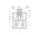
- FIG. 1 is a schematic cross-sectional view of a vacuum capacitor according to a first embodiment of the present invention. 1 is a schematic cross-sectional view of a conventional vacuum capacitor.
- the vacuum capacitor of embodiment 1, which is one aspect of the present invention shown in FIG. 1, comprises a vacuum container 1a that houses a pair of electrodes capable of securing capacitance, a fixed electrode 7 (the other electrode) and a movable electrode 8 (one electrode), and a vacuum expansion container 52 that is connected in series to the vacuum container 1a.
- the vacuum vessel 1a is sealed by a ceramic tube 2, flange tubes 3 and 4, a fixed conductor 51, and a movable conductor 6.
- the ceramic tube 2 is arranged coaxially with the fixed electrode 7 and the movable electrode 8 inside the vacuum vessel 1a.
- the flange tube 3 is coaxially interposed between one end of the ceramic tube 2 and the fixed conductor 51 (the other conductor).
- the flange tube 4 is coaxially interposed between the other end of the ceramic tube 2 and the movable conductor 6 (one of the conductors).
- the fixed electrode 7 is provided inside the vacuum vessel 1a of the fixed conductor 51, and is made up of multiple thin, roughly cylindrical electrode members of different diameters arranged coaxially at regular intervals.
- the movable electrode 8 is provided on a movable support part 91 that can move back and forth in the axial direction Y of the vacuum vessel 1a, and is made up of thin, roughly cylindrical electrode members of different diameters arranged coaxially at regular intervals so that any desired capacitance can be secured between the fixed electrode 7.
- a movable rod 10 is provided in the center of the back surface of the movable support part 91 opposite the movable electrode 8, and is reciprocated in the axial direction Y by an operating rod 12.
- the movable rod 10 is surrounded by a main bellows 50 interposed between the movable conductor 6 and the movable support part 91, and is supported coaxially with the flange tube 4 by a bearing member 11 in the movable conductor 6.
- the operating rod 12 has a male screw portion 12b at one end that screws into the female screw portion 10a of the movable rod 10, and an operating rod head portion 12a at the other end that connects to a driving source such as a motor for a vacuum capacitor, and is supported by an operating rod support 13 at the movable conductor 6 so that it can rotate freely.
- a driving source such as a motor for a vacuum capacitor
- the operating rod support 13 is composed of a screw receiving portion 13a that is provided on the movable conductor 6 and covers the bearing member 11 on the atmospheric side of the movable conductor 6, and a thrust bearing 13b that reduces the rotational torque of the operating rod 12 at this screw receiving portion 13a.
- the movable rod 10 is guided by the bearing member 11 and can move in the axial direction Y when the operating rod 12 is rotated by a drive source such as a motor. This makes it possible to change the opposing area between the movable electrode 8 and the fixed electrode 7, and obtain any desired capacitance.
- the main bellows 50 is bellows-shaped and made of a copper alloy or copper-plated flexible thin metal, and is flexible in the axial direction Y of the vacuum vessel 1.
- One end of the main bellows 50 is joined to the inner wall side of the movable conductor 6, while the other end is joined to the movable support part 91, surrounding the movable rod 10 and arranged coaxially with the flange tube 4, and the fixed electrode 7 and movable electrode 8 keep the vacuum chamber 15 airtight.
- an atmospheric chamber 16 at atmospheric pressure is formed on the movable rod 10 side of the main bellows 50 inside the vacuum vessel 1.
- a through hole 51a is formed in the center of the fixed conductor 51, through which an insulating connection rod 55 connected to the movable support part 91 is inserted.
- One end of the insulating connection rod 55 is fixed to a fixed seat 91a in the center of the movable support part 91 on the movable electrode 8 side, while the other end is fixed to a fixed seat 54a of the movable part 54 via the through hole 51a of the fixed conductor 51.
- the vacuum expansion vessel 52 has a movable part 54 connected to an insulated connection rod 55 introduced through a through hole 51a of the fixed conductor 51, and an adjustment bellows 53 interposed between the movable part 54 and the inner bottom surface of the vacuum expansion vessel 52.
- the adjustment bellows 53 is interposed between the movable part 54 and the inner end surface of the vacuum expansion vessel 52.
- the adjustment bellows 53 has the same spring constant as the main bellows 50 and a vacuum pressure equal to or lower than that of the main bellows 50.
- the vacuum chamber 15a consisting of the fixed conductor 51, the movable part 54, and the adjustment bellows 53 is kept airtight, and the movable part 54 and the insulating connection rod 55 are provided in the vacuum expansion vessel 52 so as to be movable in the axial direction Y.
- an atmospheric chamber 16a at atmospheric pressure is formed by the intake and exhaust holes 52a at the bottom of the vacuum expansion vessel 52.
- the adjustment retraction force F3 by the adjustment bellows 53 is the sum of the vacuum pressure F3v of the adjustment bellows 53 and the expansion and contraction force F3b.
- the main bellows 50, insulating connection rod 55, and adjustment bellows 53 are arranged in series in the axial direction Y, and an operating rod (not shown) is further provided on the atmospheric side of the main bellows 50 or the adjustment bellows 53.
- the movable rod 10 and the movable support part 91 move in the axial direction Y when the operating rod 12 is rotated by a driving source such as a motor in the atmosphere, expanding and contracting the main bellows 50, and the opposing area between the fixed electrode 7 and the movable electrode 8 becomes variable.
- a driving source such as a motor in the atmosphere
- expanding and contracting the main bellows 50 expanding and contracting the main bellows 50
- the opposing area between the fixed electrode 7 and the movable electrode 8 becomes variable.
- the insulated connection rod 55 expands and contracts the adjustment bellows 53 by the movable part 54 in the vacuum chamber 15a via the through hole 51a of the fixed conductor 51, and the main retraction force F2 and the adjustment retraction force F3 become forces in opposite directions and are cancelled out, so that the total retraction force F4 is only due to sliding friction.
- the total retraction force F4 is reduced by the cancellation of the main retraction force F2 of the main bellows 50 and the adjustment retraction force F3 of the adjustment bellows 53.
- the insulating connection rod 55 arranged between the main bellows 50 of the vacuum chamber 15 and the adjustment bellows 53 of the vacuum chamber 15a is insulated in the vacuum, the creepage distance is reduced, and it can be used for compressive forces with high allowable stress, and the cross section and diameter can be reduced.
- a driving source such as a motor connected to the operating rod 12 can be provided in the atmosphere, facilitating maintenance and inspection.
- the vacuum pressure F3v of the adjustment bellows 53 is equal to the vacuum pressure F2v of the main bellows 50, the vacuum pressure F3v and the vacuum pressure F2v are offset, and if the vacuum pressure F3v is equal to or lower than the vacuum pressure F2v, the total retraction force becomes F4 according to the vacuum pressure reduction force based on the conditions of the driving source such as the motor.
- the expansion and contraction force F2b of the main bellows 50 and the expansion and contraction force F3b of the adjustment bellows 53 have the same spring constant and expansion rate, and the expansion and contraction force F2b of the main bellows 50 and the expansion and contraction force F3b of the adjustment bellows 53 are forces in the opposite directions. Therefore, by connecting the main bellows 50 and the adjustment bellows 53 via the insulating connection rod 55, the expansion and contraction forces F2b and F3b are offset, and the total retraction force F4 can be reduced.
- the expansion and contraction force F3b of the adjustment bellows 53 is the same as the expansion and contraction force F2b of the main bellows 50 and is a force in the opposite direction to each other. Therefore, the expansion and contraction forces F2b and F3b are offset by the above-mentioned joint, and the total retraction force F4 can be reduced.
- the vacuum vessel 15 of the vacuum vessel 1a and the vacuum chamber 15a of the vacuum expansion vessel 52 are connected. This combines the vacuum brazing work and vacuum maintenance into one, eliminating the need to manufacture and assemble multiple sealed vessels.
- the insulating connection rod 55 is thin enough to withstand pressure, and is introduced into the vacuum expansion vessel 52 coaxially with the fixed electrode 7 and the movable electrode 8. This allows it to be joined to the adjustment bellows 53 inside the vacuum expansion vessel 52 without affecting the opposing area (capacitance) of the fixed electrode 7 and the movable electrode 8.
- the through hole 51a through which the insulating connection rod 55 is inserted prevents the insulating connection rod 55 from sliding, and the moving mechanism of the vacuum capacitor can be realized using only the bearing member 11, so there is no misalignment when using a multi-point sliding guide structure, and no need for centering adjustment.
- a driving source such as a motor can be provided in the atmosphere to enable high-speed control, resulting in a stable total retraction force F4 that is easy to fine-tune.
- the operating rod 12 is provided on the atmospheric chamber 16 side of the main bellows 50, but it may also be provided on the atmospheric chamber 16a side of the adjustment bellows 53.
Landscapes
- Engineering & Computer Science (AREA)
- Power Engineering (AREA)
- Microelectronics & Electronic Packaging (AREA)
- Fixed Capacitors And Capacitor Manufacturing Machines (AREA)
- Particle Accelerators (AREA)
Abstract
Description
Claims (6)
- 静電容量を確保可能な一対の電極を格納する真空容器と、
この真空容器と直列に連通する真空拡張容器と
を備え、
前記真空容器は、
前記一対の電極のうち一方の電極を支持する可動支持部と、
この可動支持部を前記真空容器の軸方向に往復動可能に支持する一方の導体と、
前記一対の電極のうち他方の電極を支持する他方の導体と、
前記可動支持部と前記一方の導体との間に介在する主ベローズと、
を備え、
前記真空拡張容器は、
前記可動支持部と同軸の可動部と、
この可動部と当該真空拡張容器の端部内面との間に介在する調整ベローズと、
を備え、
前記可動支持部と前記可動部は、前記一対の電極と同軸の絶縁接続ロッドにより連結されることを特徴とする真空コンデンサ。 - 前記可動支持部若しくは前記可動部を操作する操作ロッドを大気側に備えたことを特徴とする請求項1に記載の真空コンデンサ。
- 前記調整ベローズは前記主ベローズと同等以下の真空圧であることを特徴とする請求項1または2に記載の真空コンデンサ。
- 前記主ベローズ及び前記調整ベローズは同一のバネ定数及び伸縮率であることを特徴とする請求項1または2に記載の真空コンデンサ。
- 前記主ベローズ及び前記調整ベローズは、製作初期長さに対して伸び50%及び縮み50%であることを特徴とする請求項1または2に記載の真空コンデンサ。
- 前記他方の導体には、前記絶縁接続ロッドが挿通される貫通孔が形成され、
前記貫通孔を介して前記真空容器と前記真空拡張容器が連通することを特徴とする請求項1または2に記載の真空コンデンサ。
Priority Applications (2)
| Application Number | Priority Date | Filing Date | Title |
|---|---|---|---|
| CN202380068459.2A CN119948586B (zh) | 2022-09-27 | 2023-08-29 | 真空电容器 |
| US19/115,177 US12412706B2 (en) | 2022-09-27 | 2023-08-29 | Vacuum capacitor |
Applications Claiming Priority (2)
| Application Number | Priority Date | Filing Date | Title |
|---|---|---|---|
| JP2022-153213 | 2022-09-27 | ||
| JP2022153213A JP7420188B1 (ja) | 2022-09-27 | 2022-09-27 | 真空コンデンサ |
Publications (1)
| Publication Number | Publication Date |
|---|---|
| WO2024070401A1 true WO2024070401A1 (ja) | 2024-04-04 |
Family
ID=89615996
Family Applications (1)
| Application Number | Title | Priority Date | Filing Date |
|---|---|---|---|
| PCT/JP2023/031138 Ceased WO2024070401A1 (ja) | 2022-09-27 | 2023-08-29 | 真空コンデンサ |
Country Status (4)
| Country | Link |
|---|---|
| US (1) | US12412706B2 (ja) |
| JP (1) | JP7420188B1 (ja) |
| CN (1) | CN119948586B (ja) |
| WO (1) | WO2024070401A1 (ja) |
Citations (3)
| Publication number | Priority date | Publication date | Assignee | Title |
|---|---|---|---|---|
| JPS62172407U (ja) * | 1986-04-21 | 1987-11-02 | ||
| JPH0474416U (ja) * | 1990-11-09 | 1992-06-30 | ||
| JP2016522995A (ja) * | 2013-05-30 | 2016-08-04 | コメット アクチェンゲゼルシャフト | 真空可変コンデンサ |
Family Cites Families (6)
| Publication number | Priority date | Publication date | Assignee | Title |
|---|---|---|---|---|
| US2899612A (en) * | 1959-08-11 | Emmett uenn | ||
| GB1394400A (en) * | 1973-02-27 | 1975-05-14 | Marconi Co Ltd | Vacuum cavity arrangements |
| US6268995B1 (en) * | 2000-06-08 | 2001-07-31 | Jennings Technology | Double-bellows vacuum variable capacitor |
| JP4692211B2 (ja) | 2005-10-24 | 2011-06-01 | 株式会社明電舎 | 真空コンデンサ |
| CN208753156U (zh) * | 2018-10-29 | 2019-04-16 | 景德镇众凯科技有限公司 | 带双向自定位结构的可变真空电容器 |
| CN114974897B (zh) * | 2022-05-30 | 2024-08-09 | 昆山国力电子科技股份有限公司 | 容值快速转换真空电容器 |
-
2022
- 2022-09-27 JP JP2022153213A patent/JP7420188B1/ja active Active
-
2023
- 2023-08-29 WO PCT/JP2023/031138 patent/WO2024070401A1/ja not_active Ceased
- 2023-08-29 CN CN202380068459.2A patent/CN119948586B/zh active Active
- 2023-08-29 US US19/115,177 patent/US12412706B2/en active Active
Patent Citations (3)
| Publication number | Priority date | Publication date | Assignee | Title |
|---|---|---|---|---|
| JPS62172407U (ja) * | 1986-04-21 | 1987-11-02 | ||
| JPH0474416U (ja) * | 1990-11-09 | 1992-06-30 | ||
| JP2016522995A (ja) * | 2013-05-30 | 2016-08-04 | コメット アクチェンゲゼルシャフト | 真空可変コンデンサ |
Also Published As
| Publication number | Publication date |
|---|---|
| CN119948586A (zh) | 2025-05-06 |
| US12412706B2 (en) | 2025-09-09 |
| CN119948586B (zh) | 2025-09-02 |
| JP2024047620A (ja) | 2024-04-08 |
| US20250259798A1 (en) | 2025-08-14 |
| JP7420188B1 (ja) | 2024-01-23 |
Similar Documents
| Publication | Publication Date | Title |
|---|---|---|
| JP6275249B2 (ja) | 真空可変コンデンサ | |
| JP4849258B2 (ja) | 同軸導波管変換構造体および進行波管 | |
| US20110023780A1 (en) | Apparatus for vhf impedance match tuning | |
| US20240189981A1 (en) | Bending structure body | |
| WO2024070401A1 (ja) | 真空コンデンサ | |
| US4002957A (en) | Trimmable fixed hermetically sealed capacitor | |
| CN119601379A (zh) | 可精确控制容值的真空电容器 | |
| JP4861549B2 (ja) | 電流導入端子及び基板支持装置 | |
| EP3005386B1 (en) | Vacuum variable capacitor | |
| KR20110091883A (ko) | 진공 콘덴서 | |
| CN221327599U (zh) | 一种陶瓷真空断路器及电子显微镜真空系统 | |
| JP2020047491A (ja) | リレー装置 | |
| US20250273404A1 (en) | Vacuum capacitor | |
| CN119028757A (zh) | 真空灭弧室及真空断路器 | |
| US20230387878A1 (en) | Modular Electronic Cigarette | |
| CN117393367A (zh) | 一种陶瓷真空断路器及其工艺与应用 | |
| JP2026047457A (ja) | 真空コンデンサ | |
| TW202431021A (zh) | 使用扭轉剛性耦合器之調整器及使用該調整器之致動器系統 | |
| JPH0457045B2 (ja) | ||
| JPH07296998A (ja) | 高周波加速空洞の共振周波数調整用チューナ | |
| JPH05266814A (ja) | 多空胴形クライストロン | |
| JP2011233844A (ja) | 真空処理装置 |
Legal Events
| Date | Code | Title | Description |
|---|---|---|---|
| 121 | Ep: the epo has been informed by wipo that ep was designated in this application |
Ref document number: 23871642 Country of ref document: EP Kind code of ref document: A1 |
|
| WWE | Wipo information: entry into national phase |
Ref document number: 202380068459.2 Country of ref document: CN |
|
| NENP | Non-entry into the national phase |
Ref country code: DE |
|
| WWP | Wipo information: published in national office |
Ref document number: 202380068459.2 Country of ref document: CN |
|
| WWG | Wipo information: grant in national office |
Ref document number: 202380068459.2 Country of ref document: CN |
|
| 122 | Ep: pct application non-entry in european phase |
Ref document number: 23871642 Country of ref document: EP Kind code of ref document: A1 |