WO2024070360A1 - 二次電池の特性取得システム、および、二次電池の特性取得方法 - Google Patents
二次電池の特性取得システム、および、二次電池の特性取得方法 Download PDFInfo
- Publication number
- WO2024070360A1 WO2024070360A1 PCT/JP2023/030499 JP2023030499W WO2024070360A1 WO 2024070360 A1 WO2024070360 A1 WO 2024070360A1 JP 2023030499 W JP2023030499 W JP 2023030499W WO 2024070360 A1 WO2024070360 A1 WO 2024070360A1
- Authority
- WO
- WIPO (PCT)
- Prior art keywords
- charging
- ocv
- secondary battery
- mode
- soc
- Prior art date
- Legal status (The legal status is an assumption and is not a legal conclusion. Google has not performed a legal analysis and makes no representation as to the accuracy of the status listed.)
- Ceased
Links
Images





Classifications
-
- H—ELECTRICITY
- H01—ELECTRIC ELEMENTS
- H01M—PROCESSES OR MEANS, e.g. BATTERIES, FOR THE DIRECT CONVERSION OF CHEMICAL ENERGY INTO ELECTRICAL ENERGY
- H01M10/00—Secondary cells; Manufacture thereof
- H01M10/42—Methods or arrangements for servicing or maintenance of secondary cells or secondary half-cells
- H01M10/44—Methods for charging or discharging
-
- G—PHYSICS
- G01—MEASURING; TESTING
- G01R—MEASURING ELECTRIC VARIABLES; MEASURING MAGNETIC VARIABLES
- G01R31/00—Arrangements for testing electric properties; Arrangements for locating electric faults; Arrangements for electrical testing characterised by what is being tested not provided for elsewhere
- G01R31/36—Arrangements for testing, measuring or monitoring the electrical condition of accumulators or electric batteries, e.g. capacity or state of charge [SoC]
- G01R31/382—Arrangements for monitoring battery or accumulator variables, e.g. SoC
-
- G—PHYSICS
- G01—MEASURING; TESTING
- G01R—MEASURING ELECTRIC VARIABLES; MEASURING MAGNETIC VARIABLES
- G01R31/00—Arrangements for testing electric properties; Arrangements for locating electric faults; Arrangements for electrical testing characterised by what is being tested not provided for elsewhere
- G01R31/36—Arrangements for testing, measuring or monitoring the electrical condition of accumulators or electric batteries, e.g. capacity or state of charge [SoC]
- G01R31/382—Arrangements for monitoring battery or accumulator variables, e.g. SoC
- G01R31/3835—Arrangements for monitoring battery or accumulator variables, e.g. SoC involving only voltage measurements
-
- G—PHYSICS
- G01—MEASURING; TESTING
- G01R—MEASURING ELECTRIC VARIABLES; MEASURING MAGNETIC VARIABLES
- G01R31/00—Arrangements for testing electric properties; Arrangements for locating electric faults; Arrangements for electrical testing characterised by what is being tested not provided for elsewhere
- G01R31/36—Arrangements for testing, measuring or monitoring the electrical condition of accumulators or electric batteries, e.g. capacity or state of charge [SoC]
- G01R31/385—Arrangements for measuring battery or accumulator variables
-
- G—PHYSICS
- G01—MEASURING; TESTING
- G01R—MEASURING ELECTRIC VARIABLES; MEASURING MAGNETIC VARIABLES
- G01R31/00—Arrangements for testing electric properties; Arrangements for locating electric faults; Arrangements for electrical testing characterised by what is being tested not provided for elsewhere
- G01R31/36—Arrangements for testing, measuring or monitoring the electrical condition of accumulators or electric batteries, e.g. capacity or state of charge [SoC]
- G01R31/385—Arrangements for measuring battery or accumulator variables
- G01R31/387—Determining ampere-hour charge capacity or SoC
-
- G—PHYSICS
- G01—MEASURING; TESTING
- G01R—MEASURING ELECTRIC VARIABLES; MEASURING MAGNETIC VARIABLES
- G01R31/00—Arrangements for testing electric properties; Arrangements for locating electric faults; Arrangements for electrical testing characterised by what is being tested not provided for elsewhere
- G01R31/36—Arrangements for testing, measuring or monitoring the electrical condition of accumulators or electric batteries, e.g. capacity or state of charge [SoC]
- G01R31/385—Arrangements for measuring battery or accumulator variables
- G01R31/387—Determining ampere-hour charge capacity or SoC
- G01R31/388—Determining ampere-hour charge capacity or SoC involving voltage measurements
-
- H—ELECTRICITY
- H01—ELECTRIC ELEMENTS
- H01M—PROCESSES OR MEANS, e.g. BATTERIES, FOR THE DIRECT CONVERSION OF CHEMICAL ENERGY INTO ELECTRICAL ENERGY
- H01M10/00—Secondary cells; Manufacture thereof
- H01M10/42—Methods or arrangements for servicing or maintenance of secondary cells or secondary half-cells
- H01M10/48—Accumulators combined with arrangements for measuring, testing or indicating the condition of cells, e.g. the level or density of the electrolyte
-
- H—ELECTRICITY
- H02—GENERATION; CONVERSION OR DISTRIBUTION OF ELECTRIC POWER
- H02J—ELECTRIC POWER NETWORKS; CIRCUIT ARRANGEMENTS OR SYSTEMS FOR SUPPLYING OR DISTRIBUTING ELECTRIC POWER; SYSTEMS FOR STORING ELECTRIC ENERGY
- H02J7/00—Circuit arrangements for charging or discharging batteries or for supplying loads from batteries
-
- H—ELECTRICITY
- H02—GENERATION; CONVERSION OR DISTRIBUTION OF ELECTRIC POWER
- H02J—ELECTRIC POWER NETWORKS; CIRCUIT ARRANGEMENTS OR SYSTEMS FOR SUPPLYING OR DISTRIBUTING ELECTRIC POWER; SYSTEMS FOR STORING ELECTRIC ENERGY
- H02J7/00—Circuit arrangements for charging or discharging batteries or for supplying loads from batteries
- H02J7/02—Circuit arrangements for charging or discharging batteries or for supplying loads from batteries for charging batteries from AC mains by converters
- H02J7/04—Regulation of charging current or voltage
-
- H—ELECTRICITY
- H02—GENERATION; CONVERSION OR DISTRIBUTION OF ELECTRIC POWER
- H02J—ELECTRIC POWER NETWORKS; CIRCUIT ARRANGEMENTS OR SYSTEMS FOR SUPPLYING OR DISTRIBUTING ELECTRIC POWER; SYSTEMS FOR STORING ELECTRIC ENERGY
- H02J7/00—Circuit arrangements for charging or discharging batteries or for supplying loads from batteries
- H02J7/80—Circuit arrangements for charging or discharging batteries or for supplying loads from batteries including monitoring or indicating arrangements
- H02J7/82—Control of state of charge [SOC]
-
- H—ELECTRICITY
- H02—GENERATION; CONVERSION OR DISTRIBUTION OF ELECTRIC POWER
- H02J—ELECTRIC POWER NETWORKS; CIRCUIT ARRANGEMENTS OR SYSTEMS FOR SUPPLYING OR DISTRIBUTING ELECTRIC POWER; SYSTEMS FOR STORING ELECTRIC ENERGY
- H02J7/00—Circuit arrangements for charging or discharging batteries or for supplying loads from batteries
- H02J7/90—Regulation of charging or discharging current or voltage
- H02J7/96—Regulation of charging or discharging current or voltage in response to battery voltage
-
- Y—GENERAL TAGGING OF NEW TECHNOLOGICAL DEVELOPMENTS; GENERAL TAGGING OF CROSS-SECTIONAL TECHNOLOGIES SPANNING OVER SEVERAL SECTIONS OF THE IPC; TECHNICAL SUBJECTS COVERED BY FORMER USPC CROSS-REFERENCE ART COLLECTIONS [XRACs] AND DIGESTS
- Y02—TECHNOLOGIES OR APPLICATIONS FOR MITIGATION OR ADAPTATION AGAINST CLIMATE CHANGE
- Y02E—REDUCTION OF GREENHOUSE GAS [GHG] EMISSIONS, RELATED TO ENERGY GENERATION, TRANSMISSION OR DISTRIBUTION
- Y02E60/00—Enabling technologies; Technologies with a potential or indirect contribution to GHG emissions mitigation
- Y02E60/10—Energy storage using batteries
Definitions
- the present invention relates to a technology for obtaining the SOC-OCV characteristic curve of a secondary battery.
- Patent document 1 describes a battery pack that calculates the degree of deterioration of a secondary battery.
- the battery pack in patent document 1 calculates the internal resistance of the secondary battery and calculates the rate of increase in the internal resistance as the degree of deterioration of the secondary battery.
- the method of determining the degree of deterioration of a secondary battery from only the internal resistance provides only an index that represents one of the various deterioration factors of the secondary battery, and does not accurately determine the deterioration state of the secondary battery.
- a method that uses the SOC-OCV characteristic curve of a secondary battery is known as a method that can accurately determine the degree of deterioration of the secondary battery.
- the object of the present invention is therefore to easily obtain the SOC-OCV characteristic curve of a secondary battery.
- a secondary battery characteristic acquisition system includes a charge control unit, a measurement unit, a memory unit, and a characteristic curve creation unit.
- the charge control unit has a first mode in which the secondary battery is charged intermittently and a second mode in which the secondary battery is charged continuously, and selects either the first mode or the second mode to charge the secondary battery.
- the measurement unit measures the OCV of the secondary battery and the capacity from the start of charging in the first mode, and calculates the remaining capacity at each measured OCV.
- the memory unit stores the OCV and remaining capacity for multiple times.
- the characteristic curve creation unit creates a remaining capacity-OCV curve for the secondary battery using the OCV and remaining capacity for multiple times. Furthermore, after the OCVs from 0 to 100% capacity are finally collected, the remaining capacity is converted to SOC to complete the SOC-OCV curve.
- the charging control unit charges in the first mode when the terminal voltage and SOC are not stored, and charges in the second mode when the terminal voltage and SOC are stored.
- This invention makes it easy to obtain the SOC-OCV characteristic curve of a secondary battery.
- FIG. 1 is a functional block diagram showing the configuration of a battery characteristics acquisition system according to a first embodiment of the present invention.
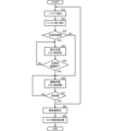
- FIG. 2 is a flowchart showing an example of a method for acquiring characteristics of a secondary battery according to the first embodiment of the present invention.
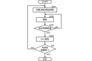
- FIG. 3 is a flowchart showing intermittent charging.
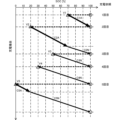
- FIG. 4 is a graph showing an example of the relationship between the SOC and the charging opportunity in the first embodiment.
- FIG. 5 shows an example of an SOC-OCV curve in the first embodiment.
- FIG. 6 is a functional block diagram showing the configuration of a battery characteristics acquisition system according to the second embodiment of the present invention.
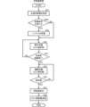
- FIG. 7 is a flowchart showing an example of a method for acquiring characteristics of a secondary battery according to the second embodiment of the present invention.
- FIG. 8 is a graph showing an example of the relationship between the SOC and the charging opportunity in the second embodiment.
- FIG. 9 shows an example of an SOC-OCV curve in the second embodiment.
- FIG. 1 is a functional block diagram showing the configuration of a battery characteristic acquisition system according to the first embodiment of the present invention.
- the battery characteristic acquisition system 10 includes a charging device 20 and a management device 30.
- the battery characteristic acquisition system 10 corresponds to the "secondary battery characteristic acquisition system" of the present invention.
- This system is applied, for example, to a system for renting equipment equipped with a battery (secondary battery) 90.
- the charging device 20 is provided, for example, at an agency that rents the equipment
- the management device 30 is provided at a management company or the like that manages the rental of this equipment.
- the system can be applied not only to equipment equipped with a battery 90, but also to a rental system for a battery 90 alone.
- the charging device 20 includes a charging control unit 21, a measuring unit 22, a communication unit 23, and a charging terminal 290. Although not shown, the charging device 20 receives power from a commercial power source or the like.
- the charging control unit 21 charges the battery 90 connected to the charging terminal 290. Specifically, the charging control unit 21 continuously supplies power according to predetermined charging conditions until the battery 90 is fully charged. At this time, the charging control unit 21 acquires identification information (individual identification information) from the battery 90.
- the measuring unit 22 measures the terminal voltage of the secondary battery. More specifically, the measuring unit 22 measures the voltage and OCV (open circuit voltage) of the battery 90 during charging.
- OCV open circuit voltage
- the measuring unit 22 measures the charging capacity value from the start of charging to the completion of charging due to full charging. More specifically, the measuring unit 22 measures the current from the start of charging to full charging and the time from the start of charging to full charging, and calculates the charging capacity value from these.
- the measurement unit 22 calculates the SOC before charging by subtracting the charging capacity value from the full charge capacity of the charged battery 90.
- the full charge capacity can be determined, for example, by referring to the identification number of the battery 90 obtained by the charging control unit 21.
- the communication unit 23 receives the identification number from the charging control unit 21, and the OCV and SCO from the measurement unit 22, and links the identification number, OCV, and SOC of the battery 90 and transmits them to the communication unit 31 of the management device 30.
- the charging control unit 21 and the measurement unit 22 execute the above-mentioned process each time the battery 90 is charged (each time a request to charge the battery 90 is received from the user), and the communication unit 23 links and transmits the identification number, OCV, and SOC of the battery 90.
- the management device 30 includes a communication unit 31 , a calculation unit 32 , and a memory unit 33 .
- the communication unit 31 receives the identification number, OCV, and SOC of the battery 90 from the communication unit 23 of the charging device 20, and outputs them to the memory unit 33.
- the communication unit 31 outputs these to the memory unit 33 every time it receives them.
- the memory unit 33 stores the identification number, OCV, and SOC from the communication unit 31 in association with each other.
- the memory unit 33 stores these data sequentially each time they are input from the communication unit 31.
- the memory unit 33 stores the identification number, OCV, and SOC of the battery 90 for the number of times it has been charged up to now. In other words, if multiple charges have been performed, the memory unit 33 stores the OCV and SOC for multiple charges corresponding to this number in association with the identification number of the battery 90.
- the calculation unit 32 includes a characteristic curve creation unit 321 and a determination unit 322.
- the calculation unit 32 is realized by, for example, a calculation processing device such as a personal computer.
- the characteristic curve creation unit 321 calculates a characteristic curve of the battery 90 using the OCV and SOC for multiple times. More specifically, the characteristic curve creation unit 321 calculates an SOC-OCV curve of the battery 90 using the OCV and SOC for multiple times. For example, the characteristic curve creation unit 321 may combine the calculation of the OCV with a method of estimating the OCV from a relaxation curve.
- the management device 30 calculates the remaining capacity-OCV curve using data obtained during these multiple charging operations. At this time, if there is a range for which the remaining capacity-OCV curve has already been calculated, the charging device 20 and the management device 30 do not acquire the OCV. On the other hand, the charging device 20 and the management device 30 additionally calculate the remaining capacity-OCV curve for a range (unmeasured range) different from the range for which the remaining capacity-OCV curve has already been calculated. The charging device 20 and the management device 30 then combine these to calculate the entire remaining capacity-OCV curve.
- FIG. 2 is a flowchart showing an example of a method for acquiring characteristics of a secondary battery according to the first embodiment of the present invention.
- an agency equipped with a charging device 20 lends a fully charged battery 90 to a user (S21) and receives the used battery 90 (S22).
- the charging device 20 acquires the unmeasured range.
- the unmeasured range is a range in which a pair of OCV and remaining capacity is not stored.
- the charging device 20 determines whether the measured voltage at the start of the current charging, i.e., the current OCV, is within the unmeasured range (S23).
- the charging device 20 determines that the OCV is within the unmeasured range regardless of the current OCV value.
- the charging device 20 determines that it is within the unmeasured range. In other words, if the OCV before the start of this charging is lower than the lowest OCV stored, the charging device 20 determines that it is within the unmeasured range.
- the charging device 20 determines that it is outside the unmeasured range (within the measured range). In other words, if the OCV before the start of the current charge is equal to or higher than the lowest OCV stored, the charging device 20 determines that it is outside the unmeasured range. Note that while the OCV cannot be measured directly during charging, if it is within the measured range, the relationship between the charging voltage and OCV is already known. Therefore, it is possible to estimate the OCV from the charging voltage based on this relationship and determine that it is outside the unmeasured range.
- the charging device 20 (charging control unit 21) has multiple charging modes. More specifically, the charging device 20 has a first mode in which the battery 90 is charged intermittently, and a second mode in which the battery 90 is charged continuously.
- the charging device 20 performs charging (intermittent charging) in the first mode (S24).
- Figure 3 is a flowchart showing intermittent charging.
- the charging device 20 continuously charges for a short period of time for measurement (S241).
- the charging device 20 stops charging, electrically opens the terminals of the battery 90 (S242), and maintains the electrically open state until the stabilization time (the time until the voltage stops changing and becomes stable) has elapsed (S243: NO).
- the charging device 20 After the stabilization time has elapsed (S243: YES), the charging device 20 measures the open terminal voltage (OCV) (S244).
- OCV open terminal voltage
- the charging device 20 repeats this measurement short-time charging (S241), electrically opening the terminals (S242), and measuring the OCV (S244) until the unmeasured range ends (S25: NO).
- the end of the unmeasured range can be detected by the point at which the OCV measured in S244 becomes equal to or greater than the previously measured OCV.
- the OCV can be measured while charging little by little, allowing many different pairs of OCV and remaining capacity to be obtained.
- the charging device 20 When the unmeasured range ends (S25: YES), the charging device 20 performs charging in the second mode (continuous charging) (S26). At this time, the charging device 20 does not measure the OCV.
- the charging device 20 continues charging (continuous charging) in the second mode described above (S26) until the battery is fully charged (S27: NO).
- the charging device 20 calculates the remaining capacity for each measured OCV (S28), and links the pair of OCV and remaining capacity to the identification information of the battery 90 and transmits it to the management device 30 (S29).
- the management device 30 calculates the remaining capacity-OCV curve of the battery 90 using the multiple sets of OCV and remaining capacity received and stored from the charging device 20. Furthermore, the management device 30 calculates the SOC-OCV curve of the battery 90 using the SOC calculated from the capacity and remaining capacity of the battery 90.
- FIG. 4 is a graph showing an example of the relationship between SOC and charging opportunity in the first embodiment.
- the SOC since the full charge capacity is not known until all the data is collected, the SOC cannot be calculated and is stored as the remaining capacity, but for the sake of simplicity, the horizontal axis is shown as SOC, and the vertical axis shows the charging opportunity.
- a circle indicates a fully charged state, and a triangle indicates the SOC before the start of charging.
- the voltage V1-V5 accompanying the triangle indicates the OCV at that time.
- C1A, C2A, and C5A indicate charging capacity values in intermittent charging
- C2N, C3N, C4N, and C5N indicate charging capacity values in continuous charging.
- the pair of OCV and remaining capacity is not stored. Therefore, in the first charge, the entire range to be charged is an unmeasured range.
- the charging device 20 measures the OCV (V1) before charging starts, and performs intermittent charging while measuring the OCV in the first mode. When the battery is fully charged, the charging device 20 calculates the charging capacity value C1A and calculates the remaining capacity at each OCV.
- the range from SOC 70% to SOC 100% is the measured range, so the range where the SOC is lower than 70% (the range where the OCV is lower than V1) is the unmeasured range.
- the charging device 20 measures the OCV (V2) and, because V2 is lower than V1, determines that it is within the unmeasured range. Therefore, in the second charge, the charging device 20 first performs intermittent charging while measuring the OCV in the first mode.
- the charging device 20 performs intermittent charging in the first mode, and when it detects that the unmeasured range has ended, it switches from the first mode to the second mode and performs continuous charging without measuring the OCV. That is, the charging device 20 performs intermittent charging in the first mode, and when the OCV reaches V1 (when the SOC reaches 70%), it switches from the first mode to the second mode and performs continuous charging without measuring the OCV.
- the second mode does not open the terminals, does not allow the stabilization time to elapse, and does not measure the OCV, so it can charge faster than the first mode even with the same charging voltage and charging current as the first mode.
- the charging device 20 calculates the charging capacity value C2A in the first mode (intermittent charging) and the charging capacity value C2N in the second mode (continuous charging), and calculates the remaining capacity at each OCV obtained in the first mode.
- the range from SOC 20% to SOC 100% is the measured range, so the range where the SOC is lower than 20% (the range where the OCV is lower than V2) is the unmeasured range.
- the charging device 20 measures the OCV (V3) before charging begins, and because V3 is higher than V2, it determines that it is outside the unmeasured range. Therefore, in the third charge, the charging device 20 performs continuous charging in the second mode until the battery is fully charged.
- the range from SOC 20% to SOC 100% is the measured range, so the range where the SOC is lower than 20% (the range where the OCV is lower than V2) is the unmeasured range.
- the charging device 20 measures the OCV (V4) before charging begins, and because V4 is higher than V2, it determines that it is outside the unmeasured range. Therefore, in the fourth charge, the charging device 20 performs continuous charging in the second mode until the battery is fully charged.
- the range from SOC 20% to SOC 100% is the measured range, so the range where the SOC is less than 10% (the range where the OCV is less than V2) is the unmeasured range.
- the charging device 20 measures the OCV (V5) and, because V5 is lower than V2, determines that it is within the unmeasured range. Therefore, in the fifth charge, the charging device 20 first performs intermittent charging while measuring the OCV in the first mode.
- the charging device 20 performs intermittent charging in the first mode, and when it detects that the unmeasured range has ended, it switches from the first mode to the second mode and performs continuous charging without measuring the OCV. In other words, the charging device 20 performs intermittent charging in the first mode, and when the OCV reaches V2 (when the SOC reaches 20%), it switches from the first mode to the second mode and performs continuous charging without measuring the OCV.
- the charging device 20 calculates the charging capacity value C5A in the first mode (intermittent charging) and the charging capacity value C5N in the second mode (continuous charging), and calculates the remaining capacity at each OCV obtained in the first mode.
- the OCV from SOC 0% to 100% (fully charged) is obtained in a total of five charges for the range from SOC 0% to SOC 100%, and the SOC can be calculated from the fully charged capacity and remaining capacity.
- the management device 30 can obtain data for pairs of SOC and OCV, such as the following:
- FIG. 5 shows an example of a remaining capacity-OCV curve in the first embodiment.
- the horizontal axis indicates SOC
- the vertical axis indicates OCV.
- Each black circle in FIG. 5 is the measurement data of OCV and SOC, as shown in FIG. 4.
- the SOC and OCV can be obtained at short intervals. This allows the management device 30 to calculate the SOC-OCV curve with greater accuracy.
- the pair of SOC and OCV is acquired at short intervals only in the range where the pair of SOC and OCV cannot be obtained. This allows faster charging in the range where the pair of SOC and OCV has already been obtained. Therefore, the battery characteristics acquisition system 10 can calculate the SOC-OCV curve with higher accuracy while preventing the charging time of the battery 90 from becoming undesirably long.
- the secondary battery characteristic acquisition technique according to the second embodiment differs from the secondary battery characteristic acquisition technique according to the first embodiment in that, under specific conditions, OCV and SOC are measured after discharging. Only the differences will be described below.
- FIG. 6 is a functional block diagram showing the configuration of a battery characteristic acquisition system according to a second embodiment of the present invention.
- the battery characteristic acquisition system 10A differs from the battery characteristic acquisition system 10 according to the first embodiment in that it includes a charge/discharge device 20A.
- the charge/discharge device 20A includes a charge/discharge control unit 21A.
- the charge/discharge control unit 21A has the function (charging function) of the charge control unit 21 shown in the first embodiment, and also has a discharging function. In other words, the charge/discharge control unit 21A can control both charging and discharging of the battery 90.
- the charge/discharge control unit 21A When measuring the set of SOC and OCV, if certain conditions are met, the charge/discharge control unit 21A performs discharge and then performs intermittent charging in the first mode for the SOC range in which the discharge was performed.
- the management device 30 calculates the SOC-OCV curve of the battery 90 using a set of remaining capacity and OCV obtained by the measurement unit 22 multiple times by charging the charge/discharge control unit 21A and charging after discharging.
- FIG. 7 is a flowchart showing an example of a method for acquiring characteristics of a secondary battery according to a second embodiment of the present invention. Note that in Fig. 7, description of charge control when discharge control is not performed is omitted, and charge control without additional discharge control is the same as in the first embodiment.
- the charging/discharging device 20A acquires the unmeasured range from the management device 30 (S31).
- the charging/discharging device 20A measures the OCV of the battery 90 for which charging has been requested before charging begins. When the discharge conditions are met (S320: YES), the charging/discharging device 20A discharges the battery 90 (S32).
- the discharge condition is either or both of the number of charges (number of charge requests) reaching a predetermined number and the OCV before charging starts being equal to or lower than the discharge permission voltage.
- the discharge condition is the number of charges
- the discharge condition is set to the fourth charge.
- the discharge condition is set to the OCV before charging starts corresponding to an SOC of 20%.
- the discharge condition is set to the fourth charge or more and the OCV before charging starts corresponding to an SOC of 20%. Note that this is just one example and is not limited to this.
- the charging/discharging device 20A After the charging/discharging device 20A reduces the SOC to 0% by discharging, it performs intermittent charging in the first mode for the unmeasured range (S33). Alternatively, the charging/discharging device 20A acquires data up to SOC 0% by intermittent discharging in the first mode.
- the charging/discharging device 20A continues intermittent charging in the first mode (S33) until the unmeasured range ends (S34: NO).
- the charging/discharging device 20A When the unmeasured range ends (S34: YES), the charging/discharging device 20A performs charging (continuous charging) in the second mode (S35). The charging/discharging device 20A performs charging (continuous charging) in the second mode described above (S35) until the battery is fully charged (S36: NO).
- the charging/discharging device 20A When the charging/discharging device 20A is fully charged (S36: YES), it calculates the remaining capacity for each measured OCV (S37), links the pair of OCV and remaining capacity to the identification information of the battery 90, and transmits it to the management device 30 (S38).
- the management device 30 calculates the SOC-OCV curve of the battery 90 using the multiple sets of OCV and remaining capacity received and stored from the charging device 20.
- the battery characteristics acquisition system 10A can forcibly acquire a set of SOC and OCV that could not be acquired by previous charging by discharging. At this time, by setting the above-mentioned discharge conditions, the battery characteristics acquisition system 10A does not discharge unconditionally, but only when certain conditions are met, thereby suppressing deterioration of the battery 90 due to discharging.
- the battery characteristics acquisition system 10A can further suppress deterioration of the battery 90 due to discharging by discharging only in the low SOC range.
- the battery characteristics acquisition system 10A can prevent the pair of remaining capacity and OCV from being acquired for an indefinite period of time, and can more reliably calculate a highly accurate remaining capacity-OCV curve.
- Fig. 8 is a graph showing an example of the relationship between SOC and charging opportunity in the second embodiment.
- the horizontal axis indicates SOC
- the vertical axis indicates charging opportunity.
- a circle indicates a fully charged state
- a triangle indicates SOC before charging starts.
- Voltages V1-V4 and V4d accompanying the triangle indicate the OCV at that time.
- C1A, C2A, and C4A indicate charging capacity values in intermittent charging
- C2N, C3N, and C4N indicate charging capacity values in continuous charging.
- the first, second, and third charging operations are the same as those in the first embodiment described above (see FIG. 4), and so a detailed description is omitted.
- the range from SOC 20% to SOC 100% is the measured range, so the range where the SOC is lower than 20% (the range where the OCV is lower than V2) is the unmeasured range.
- Charging/discharging device 20A measures the OCV (V4) before charging begins, and because V4 is lower than V2, it determines that it is within the unmeasured range. Furthermore, charging/discharging device 20A discharges battery 90 because this fourth charge satisfies the discharge condition (e.g., this is the fourth charge and the OCV is lower than the OCV at an SOC of 20%).
- charging/discharging device 20A After discharging to 0% SOC, charging/discharging device 20A measures the OCV (V4d). After that, charging/discharging device 20A first performs intermittent charging while measuring the OCV in the first mode.
- Charging/discharging device 20A performs intermittent charging in the first mode, and when it detects that the unmeasured range has ended, it switches from the first mode to the second mode and performs continuous charging without measuring the OCV. In other words, charging/discharging device 20A performs intermittent charging in the first mode, and when the OCV reaches V2 (when the SOC reaches 20%) it switches from the first mode to the second mode and performs continuous charging without measuring the OCV.
- the charging/discharging device 20A calculates the charging capacity value C4A in the first mode (intermittent charging) and the charging capacity value C4N in the second mode (continuous charging), and calculates the SOC at each OCV obtained in the first mode after discharging.
- the battery characteristic acquisition system 10A can effectively utilize the discharge process and acquire pairs of SOC and OCV for the range from SOC 0% to SOC 100% (fully charged) in a short measurement cycle.
- the management device 30 can obtain data for pairs of SOC and OCV, such as the following:
- Figure 9 shows an example of an SOC-OCV curve in the second embodiment.
- the horizontal axis indicates SOC
- the vertical axis indicates OCV.
- the white and black circles in Figure 9 represent measurement data of OCV and SOC.
- the white circles represent measurement data obtained by using discharge.
- the black circles represent measurement data obtained without using discharge (measurement data obtained by the same method as in the first embodiment).
- the SOC and OCV can be obtained at fine intervals from SOC 0% to SOC 100%. This allows the management device 30 to calculate the SOC-OCV curve with greater accuracy.
- the battery characteristics acquisition system 10A can acquire a set of SOC and OCV by discharging for a range that could not be acquired by multiple charging without discharging. This allows the battery characteristics acquisition system 10A to calculate the SOC-OCV curve with higher accuracy while preventing the number of times the battery 90 is charged from increasing significantly.
- the battery characteristic acquisition system 10A can suppress deterioration of the battery 90 due to discharge by setting a low OCV corresponding to the SOC at which discharge is permitted.
Landscapes
- Engineering & Computer Science (AREA)
- Physics & Mathematics (AREA)
- General Physics & Mathematics (AREA)
- Power Engineering (AREA)
- Manufacturing & Machinery (AREA)
- Chemical & Material Sciences (AREA)
- Chemical Kinetics & Catalysis (AREA)
- Electrochemistry (AREA)
- General Chemical & Material Sciences (AREA)
- Charge And Discharge Circuits For Batteries Or The Like (AREA)
- Secondary Cells (AREA)
Abstract
Description
本発明の第1の実施形態に係る二次電池の特性取得技術について、図を参照して説明する。図1は、本発明の第1の実施形態に係る電池特性取得システムの構成を示す機能ブロック図である。
充電装置20は、充電制御部21、測定部22、通信部23、および、充電用端子290を備える。また、図示を省略しているが、充電装置20は、商用電源等から電力供給されている。
管理装置30は、通信部31、演算部32、および、記憶部33を備える。
図4は、第1の実施形態におけるSOCと充電機会との関係の一例を示すグラフである。図4において、データが揃うまでは満充電容量が分からないため、SOCは算出できないので、残容量として蓄積が行われるが、説明を簡略化するために横軸をSOCとして示すこととして、縦軸が充電機会を示す。丸印が満充電状態を示し、三角印が充電開始前のSOCを示す。三角印に付随する電圧V1-V5は、その時のOCVを示す。C1A、C2A、C5Aは、間欠充電での充電容量値を示し、C2N、C3N、C4N、C5Nは、連続充電での充電容量値を示す。
本発明の第2の実施形態に係る二次電池の特性取得技術について、図を参照して説明する。第2の実施形態に係る二次電池の特性取得技術は、第1の実施形態に係る二次電池の特性取得技術に対して、特定条件の場合に、放電を行ってからOCVとSOCの測定を行う点で異なる。以下では、異なる箇所のみを説明する。
図7は、本発明の第2の実施形態に係る二次電池の特性取得方法の一例を示すフローチャートである。なお、図7では、放電制御を行わない場合の充電制御についての記載は省略しており、放電制御を追加しない充電制御は、第1の実施形態と同様である。
図8は、第2の実施形態におけるSOCと充電機会との関係の一例を示すグラフである。図8において、横軸がSOCを示し、縦軸が充電機会を示す。丸印が満充電状態を示し、三角印が充電開始前のSOCを示す。三角印に付随する電圧V1-V4、V4dは、その時のOCVを示す。C1A、C2A、C4Aは、間欠充電での充電容量値を示し、C2N、C3N、C4Nは、連続充電での充電容量値を示す。
20:充電装置
20A:充放電装置
21:充電制御部
21A:充放電制御部
22:測定部
23:通信部
30:管理装置
31:通信部
32:演算部
33:記憶部
90:バッテリ
290:充電用端子
321:特性曲線作成部
322:判定部
Claims (6)
- 間欠的に二次電池を充電する第1モードと、連続的に前記二次電池を充電する第2モードとを有し、前記第1モードと前記第2モードのいずれかを選択して、前記二次電池を充電する充電制御部と、
前記第1モード時に、前記二次電池の端子電圧を測定する測定し、前記測定した端子電圧毎に残容量を算出する測定部と、
前記端子電圧と前記残容量とを複数回分記憶する記憶部と、
前記複数回分の端子電圧および残容量を用いて前記二次電池の残容量-OCV曲線を作成する特性曲線作成部と、
を備え、
前記充電制御部は、
前記端子電圧と前記残容量とが記憶されていない範囲では、前記第1モードで充電を行い、
前記端子電圧と前記残容量とが記憶されている範囲では、前記第2モードで充電を行う、
二次電池の特性取得システム。 - 前記充電制御部を含み、充電制御と放電制御とを行う充放電制御部を備え、
前記充放電制御部は、
前記端子電圧および前記残容量の未測定範囲があり、放電許可条件を満たせば、
前記二次電池の放電を行った後に、前記未測定範囲に対して前記第1モードで充電を行う、
請求項1に記載の二次電池の特性取得システム。 - 前記放電許可条件は、充電開始前の端子電圧が放電許可の電圧以下の場合である、
請求項2に記載の二次電池の特性取得システム。 - 間欠的に二次電池を充電する第1モードと、連続的に前記二次電池を充電する第2モードとを有し、前記第1モードと前記第2モードのいずれかを選択して、前記二次電池を充電する充電制御ステップと、
前記第1モード時に、前記二次電池の端子電圧を測定する測定し、前記測定した端子電圧毎に残容量を算出する測定ステップと、
前記端子電圧と前記残容量とを複数回分記憶する記憶ステップと、
前記複数回分の端子電圧および残容量を用いて前記二次電池の残容量-OCV曲線を作成する特性曲線算出ステップと、
を有し、
前記充電制御ステップは、
前記端子電圧と前記残容量とが記憶されていない範囲では、前記第1モードで充電を行い、
前記端子電圧と前記残容量とが記憶されている範囲では、前記第2モードで充電を行う、
二次電池の特性取得方法。 - 前記充電制御ステップを含み、充電制御と放電制御とを行う充放電制御ステップを有し、
前記充放電制御ステップは、
前記端子電圧および前記残容量の未測定範囲があり、放電許可条件を満たせば、
前記二次電池の放電を行った後に、前記未測定範囲に対して前記第1モードで充電を行う、
請求項4に記載の二次電池の特性取得方法。 - 前記放電許可条件は、充電開始前の端子電圧が放電許可の電圧以下の場合である、
請求項5に記載の二次電池の特性取得方法。
Priority Applications (4)
| Application Number | Priority Date | Filing Date | Title |
|---|---|---|---|
| DE112023004017.6T DE112023004017T5 (de) | 2022-09-28 | 2023-08-24 | Sekundärbatteriecharakteristik-erfassungssystem und sekundärbatteriecharakteristik-erfassungsverfahren |
| GB2501202.2A GB2636003A (en) | 2022-09-28 | 2023-08-24 | Secondary battery characteristic acquisition system and secondary battery characteristic acquisition method |
| JP2024549885A JP7666755B2 (ja) | 2022-09-28 | 2023-08-24 | 二次電池の特性取得システム、および、二次電池の特性取得方法 |
| US19/076,215 US20250208219A1 (en) | 2022-09-28 | 2025-03-11 | Secondary battery characteristic acquisition system and secondary battery characteristic acquisition method |
Applications Claiming Priority (2)
| Application Number | Priority Date | Filing Date | Title |
|---|---|---|---|
| JP2022-154577 | 2022-09-28 | ||
| JP2022154577 | 2022-09-28 |
Related Child Applications (1)
| Application Number | Title | Priority Date | Filing Date |
|---|---|---|---|
| US19/076,215 Continuation US20250208219A1 (en) | 2022-09-28 | 2025-03-11 | Secondary battery characteristic acquisition system and secondary battery characteristic acquisition method |
Publications (1)
| Publication Number | Publication Date |
|---|---|
| WO2024070360A1 true WO2024070360A1 (ja) | 2024-04-04 |
Family
ID=90477325
Family Applications (1)
| Application Number | Title | Priority Date | Filing Date |
|---|---|---|---|
| PCT/JP2023/030499 Ceased WO2024070360A1 (ja) | 2022-09-28 | 2023-08-24 | 二次電池の特性取得システム、および、二次電池の特性取得方法 |
Country Status (5)
| Country | Link |
|---|---|
| US (1) | US20250208219A1 (ja) |
| JP (1) | JP7666755B2 (ja) |
| DE (1) | DE112023004017T5 (ja) |
| GB (1) | GB2636003A (ja) |
| WO (1) | WO2024070360A1 (ja) |
Citations (4)
| Publication number | Priority date | Publication date | Assignee | Title |
|---|---|---|---|---|
| JP2000341873A (ja) * | 1999-05-26 | 2000-12-08 | Matsushita Electric Works Ltd | 充電装置 |
| JP2007336654A (ja) * | 2006-06-13 | 2007-12-27 | Sanyo Electric Co Ltd | 携帯通信端末 |
| WO2018181624A1 (ja) * | 2017-03-29 | 2018-10-04 | 株式会社Gsユアサ | 蓄電量推定装置、蓄電モジュール、蓄電量推定方法、及びコンピュータプログラム |
| WO2018181620A1 (ja) * | 2017-03-29 | 2018-10-04 | 株式会社Gsユアサ | 蓄電量推定装置、蓄電モジュール、蓄電量推定方法、及びコンピュータプログラム |
Family Cites Families (1)
| Publication number | Priority date | Publication date | Assignee | Title |
|---|---|---|---|---|
| JP6260812B2 (ja) * | 2013-12-05 | 2018-01-17 | パナソニックIpマネジメント株式会社 | 電池残存容量推定装置、電池残存容量判定方法及び電池残存容量判定プログラム |
-
2023
- 2023-08-24 JP JP2024549885A patent/JP7666755B2/ja active Active
- 2023-08-24 WO PCT/JP2023/030499 patent/WO2024070360A1/ja not_active Ceased
- 2023-08-24 DE DE112023004017.6T patent/DE112023004017T5/de active Pending
- 2023-08-24 GB GB2501202.2A patent/GB2636003A/en active Pending
-
2025
- 2025-03-11 US US19/076,215 patent/US20250208219A1/en active Pending
Patent Citations (4)
| Publication number | Priority date | Publication date | Assignee | Title |
|---|---|---|---|---|
| JP2000341873A (ja) * | 1999-05-26 | 2000-12-08 | Matsushita Electric Works Ltd | 充電装置 |
| JP2007336654A (ja) * | 2006-06-13 | 2007-12-27 | Sanyo Electric Co Ltd | 携帯通信端末 |
| WO2018181624A1 (ja) * | 2017-03-29 | 2018-10-04 | 株式会社Gsユアサ | 蓄電量推定装置、蓄電モジュール、蓄電量推定方法、及びコンピュータプログラム |
| WO2018181620A1 (ja) * | 2017-03-29 | 2018-10-04 | 株式会社Gsユアサ | 蓄電量推定装置、蓄電モジュール、蓄電量推定方法、及びコンピュータプログラム |
Also Published As
| Publication number | Publication date |
|---|---|
| JPWO2024070360A1 (ja) | 2024-04-04 |
| GB2636003A (en) | 2025-06-04 |
| JP7666755B2 (ja) | 2025-04-22 |
| GB202501202D0 (en) | 2025-03-12 |
| US20250208219A1 (en) | 2025-06-26 |
| DE112023004017T5 (de) | 2025-08-21 |
Similar Documents
| Publication | Publication Date | Title |
|---|---|---|
| JP6473154B2 (ja) | 電気バッテリーの劣化状態の推定 | |
| KR100970841B1 (ko) | 배터리 전압 거동을 이용한 배터리 용량 퇴화 추정 장치 및방법 | |
| JP4767558B2 (ja) | 電源装置用状態検知装置,電源装置及び電源装置に用いられる初期特性抽出装置 | |
| US9759776B2 (en) | Battery cell state-of-health estimation method | |
| EP3171187B1 (en) | Battery state detection device, secondary battery system, program product, and battery state detection method | |
| KR100911317B1 (ko) | 배터리 전압 거동을 이용한 배터리 용량 퇴화 추정 장치 및방법 | |
| US6392415B2 (en) | Method for determining the state of charge of lead-acid rechargeable batteries | |
| KR102274383B1 (ko) | 자동차 차량 배터리의 에너지량 평가 | |
| CN101558320B (zh) | 二次电池的劣化判定装置及备用电源 | |
| US20100036627A1 (en) | Apparatus and method for determination of the state-of-charge of a battery when the battery is not in equilibrium | |
| KR20220011564A (ko) | 배터리 용량 결정 방법 및 장치, 관리 시스템 및 저장 매체 | |
| KR102101002B1 (ko) | 배터리 수명 예측 방법 | |
| JP2018082618A (ja) | バッテリ充電方法、バッテリ充電情報生成方法、及びバッテリ充電装置 | |
| CN112986842A (zh) | 电池荷电状态的估算方法、装置及设备 | |
| JPH03122581A (ja) | 電池放電保存時間予測方法および装置 | |
| EP3171186A1 (en) | Battery state detection device, secondary battery system, program product, and battery state detection method | |
| CN112986841A (zh) | 电池荷电状态的估算方法、装置及设备 | |
| WO2008099298A1 (en) | Method and apparatus for determination of the state-of-charge (soc) of a rechargeable battery | |
| CN108431617B (zh) | 用于确定电池的电荷状态的系统和方法 | |
| JP2018141665A (ja) | 電池管理方法、電池管理装置、及びコンピュータプログラム | |
| US6909261B2 (en) | Method for predicting the loading capability of an electrochemical element | |
| JP2017009577A (ja) | 状態推定装置及び状態推定方法 | |
| JP2015087344A (ja) | 容量劣化推定装置、蓄電装置および容量劣化推定方法 | |
| JP7666755B2 (ja) | 二次電池の特性取得システム、および、二次電池の特性取得方法 | |
| CN112394290A (zh) | 电池包soh的估算方法、装置、计算机设备和存储介质 |
Legal Events
| Date | Code | Title | Description |
|---|---|---|---|
| 121 | Ep: the epo has been informed by wipo that ep was designated in this application |
Ref document number: 23871601 Country of ref document: EP Kind code of ref document: A1 |
|
| WWE | Wipo information: entry into national phase |
Ref document number: 2024549885 Country of ref document: JP |
|
| ENP | Entry into the national phase |
Ref document number: 202501202 Country of ref document: GB Kind code of ref document: A Free format text: PCT FILING DATE = 20230824 |
|
| WWE | Wipo information: entry into national phase |
Ref document number: 2501202.2 Country of ref document: GB |
|
| WWE | Wipo information: entry into national phase |
Ref document number: 112023004017 Country of ref document: DE |
|
| WWP | Wipo information: published in national office |
Ref document number: 2501202.2 Country of ref document: GB |
|
| WWP | Wipo information: published in national office |
Ref document number: 112023004017 Country of ref document: DE |
|
| 122 | Ep: pct application non-entry in european phase |
Ref document number: 23871601 Country of ref document: EP Kind code of ref document: A1 |