WO2024069736A1 - カルノーバッテリー及び蓄エネルギーシステム - Google Patents
カルノーバッテリー及び蓄エネルギーシステム Download PDFInfo
- Publication number
- WO2024069736A1 WO2024069736A1 PCT/JP2022/035877 JP2022035877W WO2024069736A1 WO 2024069736 A1 WO2024069736 A1 WO 2024069736A1 JP 2022035877 W JP2022035877 W JP 2022035877W WO 2024069736 A1 WO2024069736 A1 WO 2024069736A1
- Authority
- WO
- WIPO (PCT)
- Prior art keywords
- heat
- temperature
- heat storage
- storage body
- low
- Prior art date
- Legal status (The legal status is an assumption and is not a legal conclusion. Google has not performed a legal analysis and makes no representation as to the accuracy of the status listed.)
- Ceased
Links
Images


Classifications
-
- F—MECHANICAL ENGINEERING; LIGHTING; HEATING; WEAPONS; BLASTING
- F28—HEAT EXCHANGE IN GENERAL
- F28D—HEAT-EXCHANGE APPARATUS, NOT PROVIDED FOR IN ANOTHER SUBCLASS, IN WHICH THE HEAT-EXCHANGE MEDIA DO NOT COME INTO DIRECT CONTACT
- F28D20/00—Heat storage plants or apparatus in general; Regenerative heat-exchange apparatus not covered by groups F28D17/00 or F28D19/00
- F28D20/02—Heat storage plants or apparatus in general; Regenerative heat-exchange apparatus not covered by groups F28D17/00 or F28D19/00 using latent heat
-
- F—MECHANICAL ENGINEERING; LIGHTING; HEATING; WEAPONS; BLASTING
- F24—HEATING; RANGES; VENTILATING
- F24H—FLUID HEATERS, e.g. WATER OR AIR HEATERS, HAVING HEAT-GENERATING MEANS, e.g. HEAT PUMPS, IN GENERAL
- F24H3/00—Air heaters
- F24H3/02—Air heaters with forced circulation
- F24H3/04—Air heaters with forced circulation the air being in direct contact with the heating medium, e.g. electric heating element
-
- F—MECHANICAL ENGINEERING; LIGHTING; HEATING; WEAPONS; BLASTING
- F28—HEAT EXCHANGE IN GENERAL
- F28D—HEAT-EXCHANGE APPARATUS, NOT PROVIDED FOR IN ANOTHER SUBCLASS, IN WHICH THE HEAT-EXCHANGE MEDIA DO NOT COME INTO DIRECT CONTACT
- F28D20/00—Heat storage plants or apparatus in general; Regenerative heat-exchange apparatus not covered by groups F28D17/00 or F28D19/00
- F28D20/0034—Heat storage plants or apparatus in general; Regenerative heat-exchange apparatus not covered by groups F28D17/00 or F28D19/00 using liquid heat storage material
-
- F—MECHANICAL ENGINEERING; LIGHTING; HEATING; WEAPONS; BLASTING
- F28—HEAT EXCHANGE IN GENERAL
- F28D—HEAT-EXCHANGE APPARATUS, NOT PROVIDED FOR IN ANOTHER SUBCLASS, IN WHICH THE HEAT-EXCHANGE MEDIA DO NOT COME INTO DIRECT CONTACT
- F28D20/00—Heat storage plants or apparatus in general; Regenerative heat-exchange apparatus not covered by groups F28D17/00 or F28D19/00
- F28D20/0056—Heat storage plants or apparatus in general; Regenerative heat-exchange apparatus not covered by groups F28D17/00 or F28D19/00 using solid heat storage material
-
- F—MECHANICAL ENGINEERING; LIGHTING; HEATING; WEAPONS; BLASTING
- F28—HEAT EXCHANGE IN GENERAL
- F28D—HEAT-EXCHANGE APPARATUS, NOT PROVIDED FOR IN ANOTHER SUBCLASS, IN WHICH THE HEAT-EXCHANGE MEDIA DO NOT COME INTO DIRECT CONTACT
- F28D20/00—Heat storage plants or apparatus in general; Regenerative heat-exchange apparatus not covered by groups F28D17/00 or F28D19/00
- F28D20/02—Heat storage plants or apparatus in general; Regenerative heat-exchange apparatus not covered by groups F28D17/00 or F28D19/00 using latent heat
- F28D20/021—Heat storage plants or apparatus in general; Regenerative heat-exchange apparatus not covered by groups F28D17/00 or F28D19/00 using latent heat the latent heat storage material and the heat-exchanging means being enclosed in one container
-
- F—MECHANICAL ENGINEERING; LIGHTING; HEATING; WEAPONS; BLASTING
- F28—HEAT EXCHANGE IN GENERAL
- F28D—HEAT-EXCHANGE APPARATUS, NOT PROVIDED FOR IN ANOTHER SUBCLASS, IN WHICH THE HEAT-EXCHANGE MEDIA DO NOT COME INTO DIRECT CONTACT
- F28D20/00—Heat storage plants or apparatus in general; Regenerative heat-exchange apparatus not covered by groups F28D17/00 or F28D19/00
- F28D2020/0065—Details, e.g. particular heat storage tanks, auxiliary members within tanks
- F28D2020/0078—Heat exchanger arrangements
-
- Y—GENERAL TAGGING OF NEW TECHNOLOGICAL DEVELOPMENTS; GENERAL TAGGING OF CROSS-SECTIONAL TECHNOLOGIES SPANNING OVER SEVERAL SECTIONS OF THE IPC; TECHNICAL SUBJECTS COVERED BY FORMER USPC CROSS-REFERENCE ART COLLECTIONS [XRACs] AND DIGESTS
- Y02—TECHNOLOGIES OR APPLICATIONS FOR MITIGATION OR ADAPTATION AGAINST CLIMATE CHANGE
- Y02E—REDUCTION OF GREENHOUSE GAS [GHG] EMISSIONS, RELATED TO ENERGY GENERATION, TRANSMISSION OR DISTRIBUTION
- Y02E60/00—Enabling technologies; Technologies with a potential or indirect contribution to GHG emissions mitigation
- Y02E60/14—Thermal energy storage
Definitions
- the present invention relates to a Carnot battery and an energy storage system.
- Patent Document 1 discloses a Carnot battery that stores heat by utilizing the sensible heat of solid particles such as concrete, gravel, and rocks, and then generates electricity using the stored heat.
- the Carnot battery in Patent Document 1 uses sensible heat to store heat in solid particles, so in order to keep the air supplied to the turbine at a high temperature, it is necessary to store a large amount of heated solid particles in a silo. For this reason, in the Carnot battery in Patent Document 1, heat is stored in the solid particles using a heater during times of low power demand, and the solid particles are stored in a silo, and during other times of high power demand, the stored solid particles are moved to a heat exchanger to generate power. As such, the Carnot battery in Patent Document 1 cannot stably supply power to the outside, and there is room for improvement.
- the present invention was made against this background, and aims to provide a Carnot battery and energy storage system that can stably supply electricity that absorbs output fluctuations derived from renewable energy.
- the Carnot battery according to the present invention comprises: a first conversion means for converting electrical power into heat to generate hot air; a high-temperature heat storage body including a latent heat storage material that is provided downstream of the first conversion means and receives the high-temperature air supplied from the first conversion means, stores heat therein, and releases heat; A second conversion means is provided downstream of the high-temperature storage body and recovers heat from the high-temperature air supplied from the high-temperature storage body and converts the heat into electric power; Equipped with.
- the present invention provides a Carnot battery and energy storage system that can stably supply electricity that absorbs output fluctuations derived from renewable energy.
- FIG. 1 is a diagram showing a configuration of an energy storage system according to an embodiment of the present invention.
- FIG. 1 is a diagram showing the configuration of a Carnot battery according to an embodiment of the present invention.
- 1 is a cross-sectional view showing a configuration of an electric heater and a high-temperature heat storage body according to an embodiment of the present invention.
- 2 is an enlarged front view of a portion of the high-temperature heat storage body according to the embodiment of the present invention.
- FIG. 4B is a cross-sectional view of the high-temperature heat storage body of FIG. 4A taken along line AA.
- 1 is a cross-sectional view showing a configuration of a low-temperature heat storage body according to an embodiment of the present invention.
- FIG. 1 is a diagram showing a configuration of an energy storage system according to an embodiment of the present invention.
- FIG. 1 is a diagram showing the configuration of a Carnot battery according to an embodiment of the present invention.
- 1 is a cross-sectional view
- FIG. 2 is a diagram showing a phase transition cycle in a latent heat storage material according to an embodiment of the present invention.
- 1 is a schematic diagram showing a configuration of a heat supply system according to an embodiment of the present invention.
- 1 is a cross-sectional view showing a configuration of a melting device according to an embodiment of the present invention.
- 1 is a cross-sectional view showing a configuration of a heat recovery device according to an embodiment of the present invention.
- 4 is a flowchart showing the flow of a heat supply method according to an embodiment of the present invention.
- FIG. 11 is a cross-sectional view showing the configuration of a low-temperature heat storage body according to a modified example of the present invention.
- the energy storage system uses high-temperature heat storage materials to convert grid power, which has large output fluctuations, into stable generated power, which has small output fluctuations, and uses low-temperature heat storage materials to recover the heat generated during the conversion of grid power into generated power, thereby supplying heat to heat demand areas.
- hot water is supplied to consumers through pipes, and the consumers use the hot water for hot water supply, heating, snow melting, and other purposes.
- Both the high-temperature heat storage material and the low-temperature heat storage material are phase change materials (PCMs) that store heat by utilizing latent heat.
- the latent heat storage material absorbs or releases heat by utilizing the latent heat that accompanies the phase change between liquid and solid, and therefore has a higher heat storage density than the sensible heat storage material.
- the melting point of the high-temperature heat storage material is, for example, in the range of 500°C to 700°C, and the high-temperature heat storage material releases high-temperature air in the range of 500°C to 700°C.
- the melting point of the low-temperature heat storage material is lower than the melting point of the high-temperature heat storage material, for example, in the range of 100°C to 200°C.
- the low-temperature heat storage material supplies hot water in the range of 70°C to 80°C when releasing heat.
- Grid power is power supplied from a grid power source and may include fluctuating power derived from renewable energy.
- Electricity derived from renewable energy is, for example, power obtained from wind power, solar power, or tidal power, and has the characteristic that the amount of power generated is affected by external conditions such as weather, season, and time of day.
- grid power includes fluctuating power derived from renewable energy, and is considered to be subject to short-period fluctuations. Short-period fluctuations are fluctuations in the amount of power that occur in periods of 20 minutes or less.
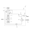
- the energy storage system 1 includes a Carnot battery 10 that converts grid power, which has large output fluctuations, into stable generated power, which has small output fluctuations, and a heat supply system 20 that recovers heat discharged from the Carnot battery 10 and supplies it to areas where heat is in demand.
- the heat supply system 20 recovers, for example, heat contained in the exhaust gas generated when the Carnot battery 10 converts heat into electricity.
- the Carnot battery 10 comprises a heat source device 11 that converts grid power into heat, a high-temperature heat storage body 12 that accumulates and releases the heat generated by the heat source device 11, and a steam power generation plant 13 that generates power by generating steam using the heat released from the high-temperature heat storage body 12.
- the heat source device 11 is an example of a first conversion means that converts power into heat to generate high-temperature air
- the steam power generation plant 13 is an example of a second conversion means that recovers heat from the high-temperature air supplied from the high-temperature heat storage body and converts it into power.
- the heat supply system 20 is configured to be detachable from the steam power plant 13 and includes a low-temperature heat storage body 21 that collects and stores heat discharged from the steam power plant 13, and a heat dissipation recovery device 22 that is configured to be able to attach the low-temperature heat storage body 21 and collects heat dissipated from the low-temperature heat storage body 21 and supplies heat to areas of heat demand.
- the heat supply system 20 may use multiple low-temperature heat storage bodies 21 sequentially or simultaneously to collect heat from the steam power plant 13 and release heat in the heat dissipation recovery device 22.
- the low-temperature heat storage body 21 is a cartridge configured so that it can be transported by a means of transportation, such as a truck.
- the low-temperature heat storage body 21 can be transported to an area of heat demand and supplied with heat while set in the heat dissipation recovery device 22.
- the low-temperature heat storage body 21 can store heat and be stored in the summer, when heat storage is easy, and then be set in the heat dissipation recovery device 22 in the winter, when heat demand is high, and heat can be supplied using the heat released from the low-temperature heat storage body 21.
- the heat source device 11 includes an electric heater 11a that generates thermal energy from electric power, and a blower 11b that blows air toward the electric heater 11a to generate a wind of high-temperature air.
- the electric heater 11a includes, for example, a resistance heating element that generates thermal energy by the Joule effect. As long as grid power is supplied, the heat source device 11 receives the grid power, converts it into heat, and continues to supply it to the high-temperature heat storage body 12.
- the high-temperature heat storage body 12 is equipped with a PCM with a large heat capacity, and is installed downstream of the heat source equipment 11.
- the high-temperature heat storage body 12 receives the high-temperature air supplied from the heat source equipment 11 and stores the heat, and releases the heat to the surrounding high-temperature air as long as heat is stored. In other words, the high-temperature heat storage body 12 adjusts the temperature of the high-temperature air flowing from the heat source equipment 11 to a constant value as long as heat is stored.
- the melting point of the PCM in the high-temperature heat storage body 12 is, for example, 570°C, and the temperature of the high-temperature air released by the high-temperature heat storage body 12 is, for example, in the range of 570°C to 600°C.
- a large heat dissipation reaction occurs when the PCM solidifies, and the inertial force is maintained because the amount of heat generated is controlled to be constant even if the system power decreases. Therefore, in the high-temperature heat storage body 12, it is preferable to store and release heat while the latent heat storage material is in a molten state inside the covering member.
- the heat source device 11 and the high-temperature heat storage body 12 are installed, for example, in a pipe 14.
- the high-temperature heat storage body 12 is formed so that a plurality of passages through which air can pass are adjacent to each other and extend in the same direction. High-temperature air blown by the blower 11b passes through each passage, and exchanges heat with the wall surface.
- the high-temperature heat storage body 12 may have, for example, a honeycomb structure with an arrangement of regular hexagonal holes, or a checkered brick structure with an arrangement of circular holes.
- the high-temperature heat storage body 12 is composed of a combination of multiple PCM capsules 12A.
- the PCM capsule 12A is formed, for example, as a sphere with a diameter of about 5 mm to 10 mm, and includes a core made of latent heat storage material, and a shell that covers the core.
- the core is preferably an aluminum alloy, for example an Al-Si alloy (4000 series) in which silicon is added to aluminum.
- the Al-Si alloy is, for example, an aluminum alloy in which 12 wt% silicon is added to aluminum.
- the shell is an example of a covering member that covers the latent heat storage material.
- the shell is preferably made of a ceramic material, for example, alumina (Al 2 O 3 ) obtained by oxidizing an aluminum alloy.
- the shell of the PCM capsule 12A is made of a heat-resistant ceramic, so that it is possible to prevent the molten core from leaking due to damage caused by heat or external force.
- the heater capacity of the heat source device 11 may be, for example, about three times the average input power from the grid power supply, and the heat storage capacity of the high-temperature heat storage body 12 may be, for example, a capacity equivalent to the amount of power consumed when the average input power from the grid power is used for 12 hours.
- the steam power plant 13 includes a steam boiler 13a that generates steam using high-temperature air from the high-temperature heat storage body 12, a superheater 13b that superheats the steam generated by the steam boiler 13a, a steam turbine 13c that extracts rotational energy from the steam supplied from the superheater 13b, a generator 13d that generates electricity using the rotational energy from the steam turbine 13c, a condenser 13e that condenses the steam discharged from the steam turbine 13c, and a water supply pump 13f that supplies the water condensed by the condenser 13e to the steam boiler 13a.
- Each part of the steam power plant 13 is connected in sequence via piping that can supply steam or water, and is configured to circulate steam or water within the steam power plant 13.
- the steam boiler 13a takes in high-temperature air from the high-temperature heat storage body 12 and converts water supplied from the water supply pump 13f into saturated steam.
- the steam boiler 13a is equipped with a drum that stores the water supplied from the water supply pump 13f, and multiple pipes that are installed inside the drum and through which the heated air from the high-temperature heat storage body 12 passes to heat the water inside the drum and generate steam.
- the steam boiler 13a receives high-temperature air in the range of 570°C to 600°C, for example, from the high-temperature heat storage body 12 and discharges 180°C air as exhaust air. This exhaust air is used for heat storage in the low-temperature heat storage body 21.
- the superheater 13b heats the saturated steam generated by the steam boiler 13a with high-temperature air from the high-temperature heat storage body 12, turning it into superheated steam.
- the steam turbine 13c converts the thermal energy of the superheated steam into rotational energy via an impeller and a rotating shaft.
- the rotating shaft of the steam turbine 13c is connected to the rotating shaft of the generator 13d, and rotates the rotating shaft of the generator 13d around its axis.
- the generator 13d converts the rotational energy of the steam turbine 13c into electrical energy.
- the power generation output of the generator 13d is set to 1 MW, the steam turbine efficiency is approximately 25%.
- the condenser 13e cools and condenses the wet steam discharged from the steam turbine 13c, while also reducing the exhaust pressure of the steam turbine 13c.
- Numerous cooling pipes are arranged inside the tank of the condenser 13e, and the wet steam inside the tank can be condensed by passing cooling water through the inside of these cooling pipes. At this time, the cooling water that passes through the cooling pipes turns into hot water, which can be used to supply heat to nearby sites.
- the water supply pump 13f is a pump that supplies the water condensed by the condenser 13e to the steam boiler 13a.
- the above is the configuration of each part of the Carnot battery 10.
- the low-temperature heat storage body 21 is a movable cartridge equipped with a PCM that melts at a lower temperature than the PCM of the high-temperature heat storage body 12.
- the melting point of the PCM of the low-temperature heat storage body 21 is preferably in the range of 140°C to 160°C, and more preferably 150°C.
- the PCM of the low-temperature heat storage body 21 melts and changes to a heat storage state due to the exhaust from the steam boiler 13a, and can supply heat in a range of, for example, 70°C to 80°C in a heat demand area.
- the PCM of the low-temperature heat storage body 21 may be expressed as "low-temperature PCM" to distinguish it from that of the high-temperature heat storage body 12.
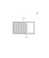
- the low-temperature heat storage body 21 includes a number of PCM capsules 21A and a container 21B that contains the PCM capsules 21A and is formed to allow heat transfer between the PCM capsules 21A and the outside.
- the low-temperature heat storage body 21 stores, moves, and releases heat from the PCM capsules 21A while keeping the PCM capsules 21A contained inside the container 21B.
- the PCM capsules 21A are low-temperature PCM encapsulated in alloy capsules, and their particle diameters are, for example, within the range of 1 mm to 10 mm.
- the capsules of the PCM capsules 21A are an example of a coating member that coats the low-temperature PCM.
- the container 21B is formed of a heat transfer material, for example, a metal material.
- the containers 21B may be formed in a cubic shape so that they can be stacked on top of each other.
- the container 21B may be provided with a door that allows the PCM capsules 21A to be inserted and removed.
- the low-temperature PCM of the low-temperature heat storage body 21 is preferably a substance that undergoes a phase transition from a molten state to a glass state via a supercooled liquid state when cooled from a molten state at a certain rate or higher.
- the supercooled liquid state is a state in which the liquid state is maintained even when cooled below the melting point, and the glass state is an amorphous state that occurs at temperatures lower than the glass transition point.
- a substance that undergoes a phase transition to a glass state stores heat when changing from a crystalline state to a molten state, and can maintain the heat storage state by changing to the glass state.
- cold crystallization can be induced and the latent heat can be released by temporarily applying heat to a substance in a glass state that exceeds the cold crystallization point.
- the latent heat is released to the outside. If the crystals obtained by cold crystallization are heated above the melting point, they can be returned to a molten state. In this way, substances that undergo a phase transition to a glass state can store and release heat through a cycle of molten state, supercooled liquid state, glass state, supercooled liquid state, cold crystallization, and crystalline state.
- the substance that undergoes a phase transition to a glass state is, for example, a polyhydric alcohol, preferably a sugar alcohol.
- the sugar alcohol is a linear or cyclic polyhydric alcohol in which the carbonyl group of the sugar is reduced.
- As the sugar alcohol it is preferable to use a eutectic formed from two or more types of sugar alcohol, and it is more preferable to use, for example, a ternary sugar alcohol formed from three types of sugar alcohol.
- An example of a ternary sugar alcohol is a eutectic of mannitol, galactitol, and inositol. By adjusting the composition of this eutectic, it is possible to change the melting point, latent heat of fusion, cold crystallization point, and latent heat of cold crystallization.
- the glass transition point of a substance that undergoes a phase transition to a glass state is preferably within the range of, for example, 10°C to 50°C
- the melting point heat storage temperature
- the cold crystallization point heat release start temperature
- a eutectic of mannitol, galactitol, and inositol has a melting point of 150°C, a glass transition point when cooling is 16.1°C, a glass transition point when heating is 15.2°C, a cold crystallization point of 72.8°C, a latent heat of fusion of 248 kJ/kg, and a latent heat of cold crystallization of 157 kJ/kg.
- a large amount of latent heat can be released from the eutectic of mannitol, galactitol, and inositol in a glass state by temporarily applying heat so that a part of the eutectic reaches a temperature of about 90°C.
- cooling to below -25°C is necessary to maintain the glassy state for about a year, it is not necessary to cool to the glassy state to maintain the heat storage state of a material that undergoes a phase transition to the glassy state. If it is rapidly cooled to a temperature around room temperature (for example, around 40°C), the material solidifies into a rubber-like state, and the heat storage state can be maintained in this state. If the heat storage state can be maintained at a temperature around room temperature, there is no need to cool the low-temperature heat storage body 21 during storage, and handling is greatly improved.
- the heat supply system 20 further includes a melter 23 that melts the low-temperature PCM in the low-temperature heat storage body 21, a quenching device 24 that quenches the low-temperature PCM, a storage warehouse 25 that stores the low-temperature heat storage body 21, and a truck 26 that transports the low-temperature heat storage body 21.
- the low-temperature heat storage body 21 moves in the order of the melter 23, the quenching device 24, the storage warehouse 25, the truck 26, and the heat radiation recovery device 22.
- the melter 23 melts the low-temperature PCM with exhaust air at 180°C from the steam boiler 13a, and releases the exhaust air at 140°C into the atmosphere.
- the quencher 24 quenches the low-temperature PCM, changing the molten low-temperature PCM into a glassy state in which heat is stored.
- the heat recovery device 22 After storage in the glassy state and transportation to a heat demand area, the heat recovery device 22 temporarily heats a portion of the low-temperature PCM to a temperature higher than the cold crystallization point, for example, around 90°C, thereby generating latent heat from the low-temperature PCM and changing the 20°C cold water into warm water in the range of 70°C to 80°C.
- the melter 23 is configured to be able to house the low-temperature heat storage body 21 inside, and melts the low-temperature PCM in the low-temperature heat storage body 21 by exhaust air from the steam boiler 13a.
- the melter 23 includes a housing 23a that houses the low-temperature heat storage body 21 inside, and a pair of heat exchangers 23b that are arranged to sandwich both sides of the low-temperature heat storage body 21 inside the housing 23a and heat both sides of the low-temperature heat storage body 21 by heat transfer.
- the quencher 24 is configured to be able to accommodate the low-temperature heat storage body 21 inside, and utilizes the cooling pipe of the condenser 13e to cause the molten low-temperature PCM contained in the low-temperature heat storage body 21 to undergo a phase transition to a glass state.
- the quencher 24 is connected to a heat exchanger in which the cooling pipe of the condenser 13e is arranged, and cools both sides of the low-temperature heat storage body 21 by heat transfer.
- the quencher 24 has the same or equivalent configuration as the melter 23, except that, for example, cooling water is caused to flow through the heat exchanger.
- the storage warehouse 25 stores the low-temperature heat storage body 21 while maintaining the heat storage state
- the truck 26 transports the low-temperature heat storage body 21 while maintaining the heat storage state to the heat demand area.
- the heat dissipation recovery device 22 is configured so that the low-temperature heat storage body 21 can be installed inside, and by temporarily heating the low-temperature heat storage body 21, cold crystallization of the low-temperature PCM is caused, and a large amount of latent heat is released. As shown in FIG.
- the heat dissipation recovery device 22 includes a housing 22a that houses the low-temperature heat storage body 21 inside, a heater 22b that is disposed within the housing 22a and temporarily heats a portion of the low-temperature PCM in the low-temperature heat storage body 21 to a temperature higher than the cold crystallization point, and a heat exchanger 22c that is disposed within the housing 22a and changes cold water supplied from the outside into hot water by transferring heat in contact with the low-temperature heat storage body 21.
- the housing 22a is provided with a door for inserting and removing the low-temperature heat storage body 21.
- a container lift machine for example, may be used to accommodate the low-temperature heat storage body 21 in the heat radiation recovery device 22.
- the heater 22b is disposed, for example, in the housing 22a so as to be in contact with the bottom and side surfaces of the low-temperature heat storage body 21, and the heat exchanger 22c is disposed, for example, on the upper side in the housing 22a.
- the components of the heat supply system 20 have been described above.
- the low-temperature heat storage body 21 is set in the melter 23, and the low-temperature PCM in the low-temperature heat storage body 21 is changed to a molten state using exhaust air from the steam boiler 13a (step S1). Specifically, as shown in FIG. 8, the low-temperature heat storage body 21 is placed on a cart 23e and placed in the melter 23, and the low-temperature PCM in the low-temperature heat storage body 21 is melted by the heat exchanger 23b heated by the exhaust air from the steam boiler 13a.
- the low-temperature heat storage body 21 that has been changed to a molten state in step S1 is set in the quenching device 24, and is quenched using cooling water from the condenser 13e, thereby changing the low-temperature PCM in the low-temperature heat storage body 21 to a glassy state (step S2).
- the low-temperature heat storage body 21 placed on the cart 23e is set in the quenching device 24 having a configuration equivalent to the melter 23 shown in Figure 8, and the low-temperature PCM in the low-temperature heat storage body 21 is quenched to below its glass transition point, whereby the low-temperature PCM changes from a supercooled liquid state to a glassy state.
- the low-temperature heat storage body 21 that has been changed to a heat storage state in step S2 is stored in the storage warehouse 25 (step S3), and when a demand for heat arises, it is transported to the heat demand area using the truck 26 (step S4).
- the low-temperature PCM is maintained at or below its glass transition point, so that the heat storage state of the low-temperature PCM can be maintained.
- the low-temperature heat storage body 21 is set in the heat dissipation recovery device 22 in the heat demand area, and heat is released from the low-temperature heat storage body 21 to supply heat to the heat demand area (step S5).
- the low-temperature PCM changes from a supercooled liquid state to a cold crystalline state and then to a crystalline state.
- cold crystallization latent heat is released at the point where cold crystallization progresses, so the latent heat can be recovered in the heat exchanger 26c, and cold water of about 20°C can be changed to hot water of about 70 to 80°C.
- the low-temperature heat storage body 21 in the crystalline state is returned to the steam power plant 13 (step S6).
- the used low-temperature heat storage body 21 may be returned to the installation site of the steam power plant 13 using a truck 26.
- the low-temperature heat storage body 21 in the crystalline state is set again in the melter 23, and the same process is repeated, so that the low-temperature heat storage body 21 can be used again as a heat source.
- the above is the flow of the heat supply method.
- the Carnot battery 10 includes a heat source device 11 that converts electric power into heat to generate high-temperature air, a high-temperature heat storage body 12 that is provided downstream of the heat source device 11 and contains a latent heat storage material that receives the high-temperature air supplied from the heat source device 11, stores heat, and releases it, and a steam power generation plant 13 that is provided downstream of the high-temperature heat storage body 12 and recovers heat from the high-temperature air supplied from the high-temperature heat storage body 12 and converts it into electric power. Therefore, the large heat capacity of the high-temperature heat storage body 12 can absorb short-period fluctuations in system power, including electricity derived from renewable energy, and as a result, system power with large output fluctuations can be stably converted into generated power with small output fluctuations.
- the energy storage system 1 includes a Carnot battery 10, a low-temperature heat storage body 21 that is detachably attached to the steam power plant 13 of the Carnot battery 10 and includes a low-temperature PCM that collects and stores heat discharged from the steam power plant 13, and a heat dissipation recovery device 22 that is configured to be able to attach the low-temperature heat storage body 21 and collects heat dissipated from the low-temperature heat storage body 21 to supply heat to areas of heat demand.
- This makes it possible to recover low-level thermal energy (surplus heat) generated by the Carnot battery 10 and supply heat to areas of heat demand. As a result, the heat utilization rate of the energy storage system 1 can be improved.
- the heat source device 11 converts electric power into heat
- the steam power plant 13 converts heat into electric power
- a heat pump may be used to convert electric power into heat and heat into electric power.
- the high-temperature heat storage body 12 has multiple passages through which air can pass that are adjacent to each other and extend in the same direction, but the present invention is not limited to this.
- the high-temperature heat storage body 12 may have any shape as long as it has a structure that allows heat exchange with the air, and may be formed, for example, with a mesh structure.
- the high-temperature heat storage body 12 is formed by combining a large number of spherical PCM capsules 12A, but the present invention is not limited to this.
- the PCM capsules 12A may be formed, for example, in a block shape or a cylindrical shape.
- the particle size of the PCM capsules 12A is within the range of 1 mm to 10 mm, but the present invention is not limited to this.
- the PCM capsules 12A may be formed as fine particles with a particle size within the range of 1 ⁇ m to 1 mm, and the fine particle PCM capsules 12A may be placed in a mold and bonded or sintered to create a high-temperature heat storage body 12 of any shape.
- the exhaust gas from the steam boiler 13a is supplied directly to the melter 23, but the present invention is not limited to this.
- a blower that sends the exhaust gas from the steam boiler 13a to the melter 23 may be provided midway in the piping that connects the steam boiler 13a and the melter 23.
- heat is stored in the low-temperature heat storage body 21 by exhaust air from the steam boiler 13a, but the present invention is not limited to this.
- heat may be stored in the low-temperature heat storage body 21 by extracting air from the steam turbine 13c.
- the container 21B that houses the multiple PCM capsules 21A has a cubic shape, but the present invention is not limited to this.
- the container 21B may be a cylindrical container having an internal space.
- the container 21B may include a housing 21a and a pair of partition plates 21b that are disposed inside the housing 21a and house the PCM capsules 21A between them. At both ends of the housing 21a, through-holes 21c are formed through which air can pass, and the partition plates 21b are formed with a number of through-holes 21d through which air can pass. Therefore, heat can be stored in the PCM capsules 21A by directly ventilating the exhaust gas from the steam boiler 13a into the inside of the housing 21a through the through-holes 21c.
- the low-temperature heat storage body 21 is provided with a large number of spherical PCM capsules 21A, but the present invention is not limited to this.
- the PCM capsules 21A may be formed, for example, in a block shape or a cylindrical shape.
- a large number of PCM capsules 21A are housed in the container 21B, but the present invention is not limited to this.
- a single low-temperature heat storage body 21 may be formed by joining a large number of PCM capsules 21A together.
- the particle size of the PCM capsules 21A is within the range of 1 mm to 10 mm, but the present invention is not limited to this.
- the particle size of the PCM capsules 21A may be within the range of 1 ⁇ m to 1 mm, and such tiny PCM capsules 21A may be joined to form a low-temperature heat storage body 21 of any shape.
- a PCM that undergoes a phase transition to a glass state is used as the low-temperature PCM, but the present invention is not limited to this. If there is no need to store the low-temperature PCM in a heat-storing state for a long period of time, a PCM that does not undergo a phase transition to a glass state may be used as the low-temperature PCM.
- the melter 23 and the quench cooler 24 are configured to heat or cool both sides of the low-temperature heat storage body 21 while the low-temperature heat storage body 21 is placed on the cart 23e, but the present invention is not limited to this.
- the melter 23 may be configured to heat the low-temperature heat storage body 21 from below using a heat exchanger installed on the bottom surface of the housing 23a.
- the quench cooler 24 may be configured to cool the low-temperature heat storage body 21 from above using a heat exchanger installed on the top surface of the housing.
- the Carnot battery and energy storage system of the present invention are useful because they can stably supply electricity that absorbs output fluctuations derived from renewable energy sources.
- Energy storage system 10 Carnot battery 11 Heat source equipment 11b Blower 12 High temperature heat storage body 12A, 21A PCM capsule 13 Steam power generation plant 13a Steam boiler 13c Steam turbine 13e Condenser 20 Heat supply system 21 Low temperature heat storage body 21B Container 22 Heat radiation recovery device 23 Melter 24 Quencher
Landscapes
- Engineering & Computer Science (AREA)
- Physics & Mathematics (AREA)
- Thermal Sciences (AREA)
- Mechanical Engineering (AREA)
- General Engineering & Computer Science (AREA)
- Chemical & Material Sciences (AREA)
- Combustion & Propulsion (AREA)
- Engine Equipment That Uses Special Cycles (AREA)
- Secondary Cells (AREA)
Priority Applications (4)
| Application Number | Priority Date | Filing Date | Title |
|---|---|---|---|
| US19/111,646 US20260092746A1 (en) | 2022-09-27 | 2022-09-27 | Carnot battery and energy storage system |
| PCT/JP2022/035877 WO2024069736A1 (ja) | 2022-09-27 | 2022-09-27 | カルノーバッテリー及び蓄エネルギーシステム |
| CN202280100211.5A CN119907897A (zh) | 2022-09-27 | 2022-09-27 | 卡诺电池和储能系统 |
| JP2024548860A JP7823213B2 (ja) | 2022-09-27 | 2022-09-27 | カルノーバッテリー及び蓄エネルギーシステム |
Applications Claiming Priority (1)
| Application Number | Priority Date | Filing Date | Title |
|---|---|---|---|
| PCT/JP2022/035877 WO2024069736A1 (ja) | 2022-09-27 | 2022-09-27 | カルノーバッテリー及び蓄エネルギーシステム |
Publications (1)
| Publication Number | Publication Date |
|---|---|
| WO2024069736A1 true WO2024069736A1 (ja) | 2024-04-04 |
Family
ID=90476621
Family Applications (1)
| Application Number | Title | Priority Date | Filing Date |
|---|---|---|---|
| PCT/JP2022/035877 Ceased WO2024069736A1 (ja) | 2022-09-27 | 2022-09-27 | カルノーバッテリー及び蓄エネルギーシステム |
Country Status (4)
| Country | Link |
|---|---|
| US (1) | US20260092746A1 (https=) |
| JP (1) | JP7823213B2 (https=) |
| CN (1) | CN119907897A (https=) |
| WO (1) | WO2024069736A1 (https=) |
Cited By (1)
| Publication number | Priority date | Publication date | Assignee | Title |
|---|---|---|---|---|
| CN119531959A (zh) * | 2024-11-26 | 2025-02-28 | 西安交通大学 | 基于相变蓄冷储能的卡诺电池系统及其多模式运行方法 |
Citations (7)
| Publication number | Priority date | Publication date | Assignee | Title |
|---|---|---|---|---|
| JPS60259890A (ja) * | 1985-05-07 | 1985-12-21 | Agency Of Ind Science & Technol | 直接熱交換方式の潜熱型蓄熱器 |
| JPH10183111A (ja) * | 1996-10-29 | 1998-07-14 | Mitsubishi Chem Corp | 蓄熱・放熱方法 |
| JP2004316958A (ja) * | 2003-04-11 | 2004-11-11 | Hitachi Metals Ltd | 熱エネルギー供給方法 |
| JP2013076401A (ja) * | 2011-09-29 | 2013-04-25 | General Electric Co <Ge> | 電力を発生するためのシステムおよび方法 |
| DE102012007211A1 (de) * | 2012-04-10 | 2013-10-10 | Hans-Jürgen Maaß | Verfahren und Vorrichtung zur thermischen Speierung von Elektroenergie |
| JP2021063629A (ja) * | 2019-10-16 | 2021-04-22 | 株式会社Ihi | 蓄エネルギー装置 |
| CN215864823U (zh) * | 2021-05-28 | 2022-02-18 | 青海能高新能源有限公司 | 一种基于熔盐相变储能的多能源联供系统 |
-
2022
- 2022-09-27 US US19/111,646 patent/US20260092746A1/en active Pending
- 2022-09-27 WO PCT/JP2022/035877 patent/WO2024069736A1/ja not_active Ceased
- 2022-09-27 CN CN202280100211.5A patent/CN119907897A/zh active Pending
- 2022-09-27 JP JP2024548860A patent/JP7823213B2/ja active Active
Patent Citations (7)
| Publication number | Priority date | Publication date | Assignee | Title |
|---|---|---|---|---|
| JPS60259890A (ja) * | 1985-05-07 | 1985-12-21 | Agency Of Ind Science & Technol | 直接熱交換方式の潜熱型蓄熱器 |
| JPH10183111A (ja) * | 1996-10-29 | 1998-07-14 | Mitsubishi Chem Corp | 蓄熱・放熱方法 |
| JP2004316958A (ja) * | 2003-04-11 | 2004-11-11 | Hitachi Metals Ltd | 熱エネルギー供給方法 |
| JP2013076401A (ja) * | 2011-09-29 | 2013-04-25 | General Electric Co <Ge> | 電力を発生するためのシステムおよび方法 |
| DE102012007211A1 (de) * | 2012-04-10 | 2013-10-10 | Hans-Jürgen Maaß | Verfahren und Vorrichtung zur thermischen Speierung von Elektroenergie |
| JP2021063629A (ja) * | 2019-10-16 | 2021-04-22 | 株式会社Ihi | 蓄エネルギー装置 |
| CN215864823U (zh) * | 2021-05-28 | 2022-02-18 | 青海能高新能源有限公司 | 一种基于熔盐相变储能的多能源联供系统 |
Cited By (1)
| Publication number | Priority date | Publication date | Assignee | Title |
|---|---|---|---|---|
| CN119531959A (zh) * | 2024-11-26 | 2025-02-28 | 西安交通大学 | 基于相变蓄冷储能的卡诺电池系统及其多模式运行方法 |
Also Published As
| Publication number | Publication date |
|---|---|
| JPWO2024069736A1 (https=) | 2024-04-04 |
| CN119907897A (zh) | 2025-04-29 |
| US20260092746A1 (en) | 2026-04-02 |
| JP7823213B2 (ja) | 2026-03-03 |
Similar Documents
| Publication | Publication Date | Title |
|---|---|---|
| Saha et al. | Global prospects and challenges of latent heat thermal energy storage: A review | |
| CN201332372Y (zh) | 利用液冷循环冷却的余热温差发电系统 | |
| US20080066736A1 (en) | Method and apparatus for solar energy storage system using gas and rock | |
| JP2022515261A (ja) | 熱の形態でエネルギーを蓄積するプラントと方法 | |
| JP2014513260A (ja) | 特に集光型太陽熱装置に適切な蓄熱設備 | |
| Datas | Ultra-high temperature thermal energy storage, transfer and conversion | |
| US12113143B2 (en) | Phase change photovoltaic thermal management device | |
| US12480718B2 (en) | Thermochemical energy storage device | |
| CN108150986A (zh) | 一种熔融盐相变蓄热电锅炉 | |
| KR20220083351A (ko) | 건축용 외장 패널 모듈 | |
| CN111075668A (zh) | 一种利用固体颗粒储热的储电系统 | |
| Zhou et al. | Study on the temperature control performance of photovoltaic module by a novel phase change material/heat pipe coupled thermal management system | |
| CN109959290A (zh) | 固体蓄热储能系统及包含其的储能电站 | |
| JP7823213B2 (ja) | カルノーバッテリー及び蓄エネルギーシステム | |
| Copus et al. | On-sun testing of Miscibility Gap Alloy thermal storage | |
| Hadiya et al. | Thermal energy storage using phase change materials: a way forward | |
| TW202311692A (zh) | 能量儲存裝置及加熱熱傳遞流體之方法 | |
| JP2017048265A (ja) | 蓄熱材料、蓄熱器および太陽熱発電システム | |
| CN101459396A (zh) | 一种温差发电热管以及温差发电装置 | |
| JP2018508708A (ja) | 発電プラントの効率の改善 | |
| Ruwa et al. | Thermal energy storage for solar power plant applications | |
| CN201349188Y (zh) | 一种热管式热电模块及其发电装置 | |
| CN113175835B (zh) | 一种利用热管的炉渣余热蓄热装置及其方法 | |
| CN115822901A (zh) | 一种光热储能发电系统 | |
| CN206944786U (zh) | 一种钢铁储能装置 |
Legal Events
| Date | Code | Title | Description |
|---|---|---|---|
| 121 | Ep: the epo has been informed by wipo that ep was designated in this application |
Ref document number: 22960800 Country of ref document: EP Kind code of ref document: A1 |
|
| WWE | Wipo information: entry into national phase |
Ref document number: 202280100211.5 Country of ref document: CN |
|
| WWE | Wipo information: entry into national phase |
Ref document number: 2024548860 Country of ref document: JP |
|
| NENP | Non-entry into the national phase |
Ref country code: DE |
|
| WWP | Wipo information: published in national office |
Ref document number: 202280100211.5 Country of ref document: CN |
|
| 122 | Ep: pct application non-entry in european phase |
Ref document number: 22960800 Country of ref document: EP Kind code of ref document: A1 |