WO2024063099A1 - Separation system and separation method - Google Patents
Separation system and separation method Download PDFInfo
- Publication number
- WO2024063099A1 WO2024063099A1 PCT/JP2023/034124 JP2023034124W WO2024063099A1 WO 2024063099 A1 WO2024063099 A1 WO 2024063099A1 JP 2023034124 W JP2023034124 W JP 2023034124W WO 2024063099 A1 WO2024063099 A1 WO 2024063099A1
- Authority
- WO
- WIPO (PCT)
- Prior art keywords
- section
- solution
- pet
- impurities
- separation
- Prior art date
Links
- 238000000926 separation method Methods 0.000 title claims abstract description 317
- 229920000139 polyethylene terephthalate Polymers 0.000 claims abstract description 329
- 239000005020 polyethylene terephthalate Substances 0.000 claims abstract description 329
- 239000012535 impurity Substances 0.000 claims abstract description 272
- 239000000178 monomer Substances 0.000 claims abstract description 245
- 239000007788 liquid Substances 0.000 claims abstract description 184
- -1 polyethylene terephthalate Polymers 0.000 claims abstract description 82
- 238000011084 recovery Methods 0.000 claims abstract description 59
- 238000000354 decomposition reaction Methods 0.000 claims abstract description 42
- OKKJLVBELUTLKV-UHFFFAOYSA-N Methanol Chemical compound OC OKKJLVBELUTLKV-UHFFFAOYSA-N 0.000 claims description 174
- 238000006243 chemical reaction Methods 0.000 claims description 111
- 239000007810 chemical reaction solvent Substances 0.000 claims description 74
- 239000002994 raw material Substances 0.000 claims description 69
- 229920000728 polyester Polymers 0.000 claims description 41
- 238000004090 dissolution Methods 0.000 claims description 27
- 238000000034 method Methods 0.000 claims description 23
- LFQSCWFLJHTTHZ-UHFFFAOYSA-N Ethanol Chemical compound CCO LFQSCWFLJHTTHZ-UHFFFAOYSA-N 0.000 claims description 19
- 150000001732 carboxylic acid derivatives Chemical class 0.000 claims description 17
- WOZVHXUHUFLZGK-UHFFFAOYSA-N dimethyl terephthalate Chemical group COC(=O)C1=CC=C(C(=O)OC)C=C1 WOZVHXUHUFLZGK-UHFFFAOYSA-N 0.000 claims description 12
- 239000000203 mixture Substances 0.000 claims description 9
- 238000005406 washing Methods 0.000 claims description 5
- 230000007246 mechanism Effects 0.000 description 42
- LYCAIKOWRPUZTN-UHFFFAOYSA-N Ethylene glycol Chemical compound OCCO LYCAIKOWRPUZTN-UHFFFAOYSA-N 0.000 description 36
- 239000002904 solvent Substances 0.000 description 30
- 239000000126 substance Substances 0.000 description 30
- 238000002844 melting Methods 0.000 description 24
- 230000008018 melting Effects 0.000 description 24
- 230000005484 gravity Effects 0.000 description 20
- 238000010586 diagram Methods 0.000 description 18
- 238000010438 heat treatment Methods 0.000 description 17
- 230000008569 process Effects 0.000 description 17
- 239000007787 solid Substances 0.000 description 16
- 238000009835 boiling Methods 0.000 description 15
- 238000007599 discharging Methods 0.000 description 8
- 239000002685 polymerization catalyst Substances 0.000 description 8
- 238000011144 upstream manufacturing Methods 0.000 description 8
- 239000000919 ceramic Substances 0.000 description 6
- 238000004064 recycling Methods 0.000 description 6
- 238000011282 treatment Methods 0.000 description 6
- 239000012632 extractable Substances 0.000 description 5
- 239000000945 filler Substances 0.000 description 5
- 238000001179 sorption measurement Methods 0.000 description 5
- 238000012691 depolymerization reaction Methods 0.000 description 4
- 238000009795 derivation Methods 0.000 description 4
- 239000003054 catalyst Substances 0.000 description 3
- 238000005119 centrifugation Methods 0.000 description 3
- 238000001816 cooling Methods 0.000 description 3
- 239000000835 fiber Substances 0.000 description 3
- 239000000049 pigment Substances 0.000 description 3
- 229920000742 Cotton Polymers 0.000 description 2
- 239000004698 Polyethylene Substances 0.000 description 2
- 239000004743 Polypropylene Substances 0.000 description 2
- 239000004793 Polystyrene Substances 0.000 description 2
- KKEYFWRCBNTPAC-UHFFFAOYSA-N Terephthalic acid Chemical compound OC(=O)C1=CC=C(C(O)=O)C=C1 KKEYFWRCBNTPAC-UHFFFAOYSA-N 0.000 description 2
- QPKOBORKPHRBPS-UHFFFAOYSA-N bis(2-hydroxyethyl) terephthalate Chemical compound OCCOC(=O)C1=CC=C(C(=O)OCCO)C=C1 QPKOBORKPHRBPS-UHFFFAOYSA-N 0.000 description 2
- 230000003247 decreasing effect Effects 0.000 description 2
- 230000000694 effects Effects 0.000 description 2
- 238000001914 filtration Methods 0.000 description 2
- 239000000463 material Substances 0.000 description 2
- 239000000155 melt Substances 0.000 description 2
- 238000002156 mixing Methods 0.000 description 2
- 229920003023 plastic Polymers 0.000 description 2
- 239000004033 plastic Substances 0.000 description 2
- 229920000573 polyethylene Polymers 0.000 description 2
- 229920000642 polymer Polymers 0.000 description 2
- 230000000379 polymerizing effect Effects 0.000 description 2
- 229920001155 polypropylene Polymers 0.000 description 2
- 229920002223 polystyrene Polymers 0.000 description 2
- 229920000915 polyvinyl chloride Polymers 0.000 description 2
- 239000004800 polyvinyl chloride Substances 0.000 description 2
- 230000000717 retained effect Effects 0.000 description 2
- 238000004062 sedimentation Methods 0.000 description 2
- 230000032258 transport Effects 0.000 description 2
- XLYOFNOQVPJJNP-UHFFFAOYSA-N water Substances O XLYOFNOQVPJJNP-UHFFFAOYSA-N 0.000 description 2
- 241000534000 Berula erecta Species 0.000 description 1
- 239000004480 active ingredient Substances 0.000 description 1
- 125000003178 carboxy group Chemical group [H]OC(*)=O 0.000 description 1
- 230000008859 change Effects 0.000 description 1
- 150000001875 compounds Chemical class 0.000 description 1
- 239000000470 constituent Substances 0.000 description 1
- 230000007423 decrease Effects 0.000 description 1
- 239000000295 fuel oil Substances 0.000 description 1
- XLYOFNOQVPJJNP-ZSJDYOACSA-N heavy water Substances [2H]O[2H] XLYOFNOQVPJJNP-ZSJDYOACSA-N 0.000 description 1
- 239000002184 metal Substances 0.000 description 1
- 229910052751 metal Inorganic materials 0.000 description 1
- 150000002736 metal compounds Chemical class 0.000 description 1
- 150000002739 metals Chemical class 0.000 description 1
- 238000012986 modification Methods 0.000 description 1
- 230000004048 modification Effects 0.000 description 1
- 230000002794 monomerizing effect Effects 0.000 description 1
- 239000002245 particle Substances 0.000 description 1
- 230000037361 pathway Effects 0.000 description 1
- 238000006116 polymerization reaction Methods 0.000 description 1
- 230000001172 regenerating effect Effects 0.000 description 1
- 238000003756 stirring Methods 0.000 description 1
- 238000006467 substitution reaction Methods 0.000 description 1
- 239000013076 target substance Substances 0.000 description 1
- 239000002699 waste material Substances 0.000 description 1
Images


Classifications
-
- C—CHEMISTRY; METALLURGY
- C08—ORGANIC MACROMOLECULAR COMPOUNDS; THEIR PREPARATION OR CHEMICAL WORKING-UP; COMPOSITIONS BASED THEREON
- C08G—MACROMOLECULAR COMPOUNDS OBTAINED OTHERWISE THAN BY REACTIONS ONLY INVOLVING UNSATURATED CARBON-TO-CARBON BONDS
- C08G63/00—Macromolecular compounds obtained by reactions forming a carboxylic ester link in the main chain of the macromolecule
- C08G63/02—Polyesters derived from hydroxycarboxylic acids or from polycarboxylic acids and polyhydroxy compounds
- C08G63/12—Polyesters derived from hydroxycarboxylic acids or from polycarboxylic acids and polyhydroxy compounds derived from polycarboxylic acids and polyhydroxy compounds
- C08G63/123—Polyesters derived from hydroxycarboxylic acids or from polycarboxylic acids and polyhydroxy compounds derived from polycarboxylic acids and polyhydroxy compounds the acids or hydroxy compounds containing carbocyclic rings
- C08G63/127—Acids containing aromatic rings
-
- C—CHEMISTRY; METALLURGY
- C08—ORGANIC MACROMOLECULAR COMPOUNDS; THEIR PREPARATION OR CHEMICAL WORKING-UP; COMPOSITIONS BASED THEREON
- C08J—WORKING-UP; GENERAL PROCESSES OF COMPOUNDING; AFTER-TREATMENT NOT COVERED BY SUBCLASSES C08B, C08C, C08F, C08G or C08H
- C08J11/00—Recovery or working-up of waste materials
- C08J11/04—Recovery or working-up of waste materials of polymers
- C08J11/06—Recovery or working-up of waste materials of polymers without chemical reactions
- C08J11/08—Recovery or working-up of waste materials of polymers without chemical reactions using selective solvents for polymer components
-
- C—CHEMISTRY; METALLURGY
- C08—ORGANIC MACROMOLECULAR COMPOUNDS; THEIR PREPARATION OR CHEMICAL WORKING-UP; COMPOSITIONS BASED THEREON
- C08J—WORKING-UP; GENERAL PROCESSES OF COMPOUNDING; AFTER-TREATMENT NOT COVERED BY SUBCLASSES C08B, C08C, C08F, C08G or C08H
- C08J11/00—Recovery or working-up of waste materials
- C08J11/04—Recovery or working-up of waste materials of polymers
- C08J11/10—Recovery or working-up of waste materials of polymers by chemically breaking down the molecular chains of polymers or breaking of crosslinks, e.g. devulcanisation
- C08J11/18—Recovery or working-up of waste materials of polymers by chemically breaking down the molecular chains of polymers or breaking of crosslinks, e.g. devulcanisation by treatment with organic material
- C08J11/22—Recovery or working-up of waste materials of polymers by chemically breaking down the molecular chains of polymers or breaking of crosslinks, e.g. devulcanisation by treatment with organic material by treatment with organic oxygen-containing compounds
- C08J11/24—Recovery or working-up of waste materials of polymers by chemically breaking down the molecular chains of polymers or breaking of crosslinks, e.g. devulcanisation by treatment with organic material by treatment with organic oxygen-containing compounds containing hydroxyl groups
Landscapes
- Chemical & Material Sciences (AREA)
- Health & Medical Sciences (AREA)
- Chemical Kinetics & Catalysis (AREA)
- Medicinal Chemistry (AREA)
- Polymers & Plastics (AREA)
- Organic Chemistry (AREA)
- Life Sciences & Earth Sciences (AREA)
- Sustainable Development (AREA)
- Separation, Recovery Or Treatment Of Waste Materials Containing Plastics (AREA)
Abstract
The separation system has a solid-liquid separation unit that removes impurities by solid-liquid separation from a dissolved solution that contains a PET solution in which polyethylene terephthalate has been dissolved in monomers derived from decomposition of polyethylene terephthalate and impurities, which are components other than polyethylene terephthalate, and a recovery unit that recovers the monomers derived from the decomposition of polyethylene terephthalate from the impurities separated by the solid-liquid separation unit.
Description
本開示は、分離システム及び分離方法に関する。
The present disclosure relates to a separation system and a separation method.
例えばポリエステルをリサイクルするために、ポリエステルから不純物を分離する技術が知られている。特許文献1には、ポリエチレンテレフタレート(PET)廃棄物をエチレングリコール(EG)に投入して解重合を行って、ビス(β-ヒドロキシエチル)テレフタレート(BHET)を得る旨、及び、解重合の反応中又は反応後に、PET以外の異物をろ過機により除去する旨が記載されている。
For example, techniques for separating impurities from polyester are known in order to recycle it. Patent Document 1 describes that polyethylene terephthalate (PET) waste is put into ethylene glycol (EG) and depolymerized to obtain bis(β-hydroxyethyl) terephthalate (BHET), and that the depolymerization reaction is It is stated that foreign substances other than PET are removed by a filter during or after the reaction.
ポリエステルを回収する対象に含まれ、リサイクルのために除去する異物は、種々の形状となる。ポリエステルを効率よく回収するためには、異物を適切に分離する必要がある。
Foreign substances included in polyester recovery and removed for recycling come in various shapes. In order to efficiently recover polyester, it is necessary to appropriately separate foreign substances.
本開示は、上述した課題を解決するものであり、PETと異物とを適切に分離可能な分離システム及び分離方法を提供することを目的とする。
The present disclosure solves the above-mentioned problems, and aims to provide a separation system and a separation method that can appropriately separate PET and foreign substances.
上述した課題を解決し、目的を達成するために、本開示に係る分離システムは、ポリエチレンテレフタラートの分解由来のモノマーにポリエチレンテレフタラートが溶解したPET溶液と、前記ポリエチレンテレフタラート以外の成分である不純物とを含む溶解液から、固液分離で不純物を除去する固液分離部と、前記固液分離部で分離した不純物からポリエチレンテレフタラートの分解由来のモノマーを回収する回収部と、を有する。
In order to solve the above problems and achieve the objectives, a separation system according to the present disclosure includes a PET solution in which polyethylene terephthalate is dissolved in a monomer derived from decomposition of polyethylene terephthalate, and a component other than the polyethylene terephthalate. A solid-liquid separation section that removes impurities from a solution containing impurities by solid-liquid separation, and a recovery section that recovers monomers derived from decomposition of polyethylene terephthalate from the impurities separated in the solid-liquid separation section.
上述した課題を解決し、目的を達成するために、本開示に係る分離方法は、ポリエチレンテレフタラートの分解由来のモノマーにポリエチレンテレフタラートが溶解したPET溶液と、前記ポリエチレンテレフタラート以外の成分である不純物とを含む溶解液から、固液分離で不純物を除去するステップと、固液分離で除去した不純物からポリエチレンテレフタラートの分解由来のモノマーを回収する回収ステップと、を有する。
In order to solve the above problems and achieve the objectives, the separation method according to the present disclosure includes a PET solution in which polyethylene terephthalate is dissolved in a monomer derived from the decomposition of polyethylene terephthalate, and a component other than the polyethylene terephthalate. The method includes a step of removing impurities from a solution containing impurities by solid-liquid separation, and a recovery step of recovering monomers derived from decomposition of polyethylene terephthalate from the impurities removed by solid-liquid separation.
本開示によれば、PETと異物とを適切に分離することができる。
According to the present disclosure, PET and foreign matter can be appropriately separated.
以下に添付図面を参照して、本発明の好適な実施形態を詳細に説明する。なお、この実施形態により本発明が限定されるものではなく、また、実施形態が複数ある場合には、各実施形態を組み合わせて構成するものも含むものである。
Preferred embodiments of the present invention will be described in detail below with reference to the accompanying drawings. It should be noted that the present invention is not limited to this embodiment, and if there are multiple embodiments, the present invention may be configured by combining each embodiment.
(第1実施形態)
(リサイクル工程)
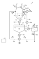
図1は、本実施形態におけるポリエチレンテレフタラートのリサイクル工程の模式図である。本実施形態においては、PET(ポリエチレンテレフタラート)原料Pmを解重合してモノマー化し、モノマーを再度重合させることで、PET原料Pmをリサイクル(再生)する工程を行う。具体的には、図1に示すように、PET原料Pmをフレーク化し(ステップS100)、フレーク化したPET原料Pmをカルボン酸由来のモノマーDに溶解させてPET溶解液を生成し(ステップS101)、溶解液から異物を除去し(ステップS102)、異物を除去した溶解液を反応溶媒Mと混合して解重合し(ステップS103)、解重合したポリエステルのモノマーを精製(分離)してカルボン酸由来のモノマーDとアルコール成分のモノマーEとを生成し(ステップS104)、モノマーDを加水分解して反応溶媒Mを分離し(ステップS106)、モノマーDが加水分解して生成されたモノマーFと、モノマーEとを重合させて(ステップS108)、PET原料Pmを再生する。なお、本実施形態の分離システム1を採用したリサイクル工程は、ステップS100のフレーク化を省略してもよいし、ステップS108のように再重合する処理まで行わずに、ステップS102、ステップS104に示すモノマーD、E、及びステップS106に示すモノマーFを回収する処理のみを行ってよい。 (First embodiment)
(Recycling process)
FIG. 1 is a schematic diagram of the polyethylene terephthalate recycling process in this embodiment. In this embodiment, a step of recycling (regenerating) the PET (polyethylene terephthalate) raw material Pm is performed by depolymerizing and monomerizing the PET (polyethylene terephthalate) raw material Pm and polymerizing the monomer again. Specifically, as shown in FIG. 1, PET raw material Pm is flaked (step S100), and the flaked PET raw material Pm is dissolved in carboxylic acid-derived monomer D to generate a PET solution (step S101). , foreign substances are removed from the solution (step S102), the solution from which foreign substances have been removed is mixed with reaction solvent M and depolymerized (step S103), and the depolymerized polyester monomer is purified (separated) to obtain carboxylic acid. The monomer D derived from the alcohol component and the monomer E of the alcohol component are produced (step S104), and the monomer D is hydrolyzed to separate the reaction solvent M (step S106). , and monomer E (step S108) to regenerate the PET raw material Pm. In addition, in the recycling process employing the separation system 1 of this embodiment, the flaking process in step S100 may be omitted, or the process shown in steps S102 and S104 may be performed without performing the repolymerization process as in step S108. Only the process of recovering monomers D, E, and monomer F shown in step S106 may be performed.
(リサイクル工程)
図1は、本実施形態におけるポリエチレンテレフタラートのリサイクル工程の模式図である。本実施形態においては、PET(ポリエチレンテレフタラート)原料Pmを解重合してモノマー化し、モノマーを再度重合させることで、PET原料Pmをリサイクル(再生)する工程を行う。具体的には、図1に示すように、PET原料Pmをフレーク化し(ステップS100)、フレーク化したPET原料Pmをカルボン酸由来のモノマーDに溶解させてPET溶解液を生成し(ステップS101)、溶解液から異物を除去し(ステップS102)、異物を除去した溶解液を反応溶媒Mと混合して解重合し(ステップS103)、解重合したポリエステルのモノマーを精製(分離)してカルボン酸由来のモノマーDとアルコール成分のモノマーEとを生成し(ステップS104)、モノマーDを加水分解して反応溶媒Mを分離し(ステップS106)、モノマーDが加水分解して生成されたモノマーFと、モノマーEとを重合させて(ステップS108)、PET原料Pmを再生する。なお、本実施形態の分離システム1を採用したリサイクル工程は、ステップS100のフレーク化を省略してもよいし、ステップS108のように再重合する処理まで行わずに、ステップS102、ステップS104に示すモノマーD、E、及びステップS106に示すモノマーFを回収する処理のみを行ってよい。 (First embodiment)
(Recycling process)
FIG. 1 is a schematic diagram of the polyethylene terephthalate recycling process in this embodiment. In this embodiment, a step of recycling (regenerating) the PET (polyethylene terephthalate) raw material Pm is performed by depolymerizing and monomerizing the PET (polyethylene terephthalate) raw material Pm and polymerizing the monomer again. Specifically, as shown in FIG. 1, PET raw material Pm is flaked (step S100), and the flaked PET raw material Pm is dissolved in carboxylic acid-derived monomer D to generate a PET solution (step S101). , foreign substances are removed from the solution (step S102), the solution from which foreign substances have been removed is mixed with reaction solvent M and depolymerized (step S103), and the depolymerized polyester monomer is purified (separated) to obtain carboxylic acid. The monomer D derived from the alcohol component and the monomer E of the alcohol component are produced (step S104), and the monomer D is hydrolyzed to separate the reaction solvent M (step S106). , and monomer E (step S108) to regenerate the PET raw material Pm. In addition, in the recycling process employing the separation system 1 of this embodiment, the flaking process in step S100 may be omitted, or the process shown in steps S102 and S104 may be performed without performing the repolymerization process as in step S108. Only the process of recovering monomers D, E, and monomer F shown in step S106 may be performed.
(PET原料)
本実施形態において解重合の対象となるPET原料Pmは、PET(ポリエチレンテレフタラート)を含有する物質である。PET原料Pmは、PET成分のみを含有するものに限られず、PET成分以外の成分も含む。PET原料Pmに含まれるPET以外の成分としては、例えば、PET以外のポリエチレン、ポリスチレン、ポリプロピレン、ポリ塩化ビニルなどのプラスチック類、金属類、顔料、及び重合触媒などが挙げられる。PET原料Pmとしては、PETやその他の成分が繊維状に編み込まれた衣服も例示される。以下、PET原料Pmに含まれるPET以外の成分を、不純物Rとする。 (PET raw material)
The PET raw material Pm to be depolymerized in this embodiment is a substance containing PET (polyethylene terephthalate). The PET raw material Pm is not limited to containing only the PET component, but also includes components other than the PET component. Examples of components other than PET contained in the PET raw material Pm include plastics other than PET such as polyethylene, polystyrene, polypropylene, and polyvinyl chloride, metals, pigments, and polymerization catalysts. Examples of the PET raw material Pm include clothing in which PET and other components are woven into fibers. Hereinafter, components other than PET contained in the PET raw material Pm will be referred to as impurities R.
(反応溶媒)
反応溶媒Mは、PETと反応して、PETを解重合させる溶媒である。反応溶媒Mは、例えば、メタノール、エタノール、水及びエチレングリコールのうちの少なくとも1つであってよい。 (reaction solvent)
The reaction solvent M is a solvent that reacts with PET to depolymerize PET. The reaction solvent M may be, for example, at least one of methanol, ethanol, water and ethylene glycol.
反応溶媒Mは、PETと反応して、PETを解重合させる溶媒である。反応溶媒Mは、例えば、メタノール、エタノール、水及びエチレングリコールのうちの少なくとも1つであってよい。 (reaction solvent)
The reaction solvent M is a solvent that reacts with PET to depolymerize PET. The reaction solvent M may be, for example, at least one of methanol, ethanol, water and ethylene glycol.
(ポリエチレンテレフタレート分解由来のモノマー)
ポリエチレンテレフタラートの分解由来のモノマーは、ポリエチレンテレフタラート(PET)の解重合反応により生成されるモノマーである。ポリエチレンテレフタラートの分解由来のモノマーは、カルボン酸由来のモノマーDと、アルコール成分のモノマーEと、を含む。 (Monomer derived from polyethylene terephthalate decomposition)
The monomer derived from the decomposition of polyethylene terephthalate is a monomer produced by the depolymerization reaction of polyethylene terephthalate (PET). The monomer derived from the decomposition of polyethylene terephthalate includes a monomer D derived from a carboxylic acid and a monomer E of an alcohol component.
(カルボン酸由来のモノマー)
カルボン酸由来のモノマーDは、PETの解重合反応により生成された、カルボキシル基を有するモノマーである。モノマーDは、例えば、カルボン酸ジメチルやカルボン酸ジエチルであってよい。さらに言えば、モノマーDは、テレフタル酸のモノマーであることが好ましく、例えばテレフタル酸ジメチル(DMT)であってよい。 (monomer derived from carboxylic acid)
Monomer D derived from carboxylic acid is a monomer having a carboxyl group and produced by a depolymerization reaction of PET. Monomer D may be, for example, dimethyl carboxylate or diethyl carboxylate. Furthermore, monomer D is preferably a monomer of terephthalic acid, and may be, for example, dimethyl terephthalate (DMT).
(アルコール成分のモノマー)
アルコール成分のモノマーEは、PETの解重合反応により生成された、アルコール成分のモノマーである。モノマーEは、例えば、ジヒドロキシ化合物(二価アルコール)であってよく、さらに言えば、エチレングリコール(EG)であってよい。 (monomer of alcohol component)
The alcohol component monomer E is an alcohol component monomer produced by a depolymerization reaction of PET. The monomer E may be, for example, a dihydroxy compound (dihydric alcohol) or even ethylene glycol (EG).
以降においては、反応溶媒Mがメタノールであり、モノマーDがDMTであり、モノマーEがEGである場合を例にして説明する。
Hereinafter, an example will be explained in which the reaction solvent M is methanol, the monomer D is DMT, and the monomer E is EG.
(分離システム)
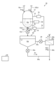
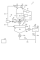
図2は、第1実施形態に係る分離システムの模式図である。第1実施形態に係る分離システム1は、PET原料Pmに含まれるポリエステルをモノマー化して、モノマーD、Eを生成するシステムである。図1に示すように、分離システム1は、原料貯留部10と、溶解部12と、固液分離部13と、貯留部20と、除去部26と、反応溶媒貯留部14と、反応部16と、分離部18と、制御部30と、を有する。 (separation system)
FIG. 2 is a schematic diagram of the separation system according to the first embodiment. The separation system 1 according to the first embodiment is a system that monomerizes polyester contained in the PET raw material Pm to generate monomers D and E. As shown in FIG. 1, the separation system 1 includes a rawmaterial storage section 10, a dissolution section 12, a solid-liquid separation section 13, a storage section 20, a removal section 26, a reaction solvent storage section 14, and a reaction section 16. , a separation section 18 , and a control section 30 .
図2は、第1実施形態に係る分離システムの模式図である。第1実施形態に係る分離システム1は、PET原料Pmに含まれるポリエステルをモノマー化して、モノマーD、Eを生成するシステムである。図1に示すように、分離システム1は、原料貯留部10と、溶解部12と、固液分離部13と、貯留部20と、除去部26と、反応溶媒貯留部14と、反応部16と、分離部18と、制御部30と、を有する。 (separation system)
FIG. 2 is a schematic diagram of the separation system according to the first embodiment. The separation system 1 according to the first embodiment is a system that monomerizes polyester contained in the PET raw material Pm to generate monomers D and E. As shown in FIG. 1, the separation system 1 includes a raw
(原料貯留部)
原料貯留部10は、PET原料Pmが導入されて、PET原料Pmが貯留される槽(ホッパ)である。本実施形態においては、原料貯留部10には、フレーク化されたPET原料Pmが貯留されるが、PET原料Pmの形状や大きさは任意であってよい。原料貯留部10は、導入管10aを介して溶解部12に接続されている。原料貯留部10内のPET原料Pmは、導入管10aを通って、溶解部12に供給される。導入管10aには、原料貯留部10から溶解部12に供給されるPET原料Pmの量を調整する調整部10bが設けられている。調整部10bは、例えば開閉弁であり、開状態の場合に、原料貯留部10内のPET原料Pmを溶解部12に供給させ、閉状態の場合に、原料貯留部10内のPET原料Pmの溶解部12への供給を停止させる。ただし、調整部10bは、開閉弁であることに限られず、溶解部12へのPET原料Pmの供給を調整可能な任意の機構であってよい。また、PET原料Pmは、原料貯留部10、導入管10a、調整部10bを介さず、直接溶解部12に供給してもよい。 (Raw material storage section)
The rawmaterial storage section 10 is a tank (hopper) into which the PET raw material Pm is introduced and stored. In the present embodiment, the flaked PET raw material Pm is stored in the raw material storage section 10, but the shape and size of the PET raw material Pm may be arbitrary. The raw material storage section 10 is connected to the melting section 12 via an introduction pipe 10a. The PET raw material Pm in the raw material storage section 10 is supplied to the melting section 12 through the introduction pipe 10a. The introduction pipe 10a is provided with an adjustment section 10b that adjusts the amount of PET raw material Pm supplied from the raw material storage section 10 to the melting section 12. The adjustment section 10b is, for example, an on-off valve, and when in the open state, supplies the PET raw material Pm in the raw material storage section 10 to the melting section 12, and when in the closed state, supplies the PET raw material Pm in the raw material storage section 10. The supply to the melting section 12 is stopped. However, the adjustment section 10b is not limited to an on-off valve, and may be any mechanism that can adjust the supply of the PET raw material Pm to the melting section 12. Further, the PET raw material Pm may be directly supplied to the melting section 12 without going through the raw material storage section 10, the introduction pipe 10a, and the adjustment section 10b.
原料貯留部10は、PET原料Pmが導入されて、PET原料Pmが貯留される槽(ホッパ)である。本実施形態においては、原料貯留部10には、フレーク化されたPET原料Pmが貯留されるが、PET原料Pmの形状や大きさは任意であってよい。原料貯留部10は、導入管10aを介して溶解部12に接続されている。原料貯留部10内のPET原料Pmは、導入管10aを通って、溶解部12に供給される。導入管10aには、原料貯留部10から溶解部12に供給されるPET原料Pmの量を調整する調整部10bが設けられている。調整部10bは、例えば開閉弁であり、開状態の場合に、原料貯留部10内のPET原料Pmを溶解部12に供給させ、閉状態の場合に、原料貯留部10内のPET原料Pmの溶解部12への供給を停止させる。ただし、調整部10bは、開閉弁であることに限られず、溶解部12へのPET原料Pmの供給を調整可能な任意の機構であってよい。また、PET原料Pmは、原料貯留部10、導入管10a、調整部10bを介さず、直接溶解部12に供給してもよい。 (Raw material storage section)
The raw
(溶解部)
溶解部12は、溶解液Pdが貯留される槽である。溶解液Pdは、PET原料PmとモノマーDとが混合して生成される溶液である。ここで、PET原料Pmに含まれるPET成分は、モノマーDに溶解するが、PET原料Pmに含まれるPET以外の成分である不純物Rは、モノマーDに溶解せずに残存する。従って、溶解液Pdには、PET原料Pmに含まれるPETがモノマーDに溶解したPET溶液Pと、PET原料Pmに含まれる不純物Rとが含まれているといえる。 (melting part)
The dissolvingsection 12 is a tank in which the dissolving solution Pd is stored. The solution Pd is a solution produced by mixing the PET raw material Pm and the monomer D. Here, the PET component contained in the PET raw material Pm is dissolved in the monomer D, but the impurity R, which is a component other than PET and contained in the PET raw material Pm, remains without being dissolved in the monomer D. Therefore, it can be said that the solution Pd contains the PET solution P in which PET contained in the PET raw material Pm is dissolved in the monomer D, and the impurity R contained in the PET raw material Pm.
溶解部12は、溶解液Pdが貯留される槽である。溶解液Pdは、PET原料PmとモノマーDとが混合して生成される溶液である。ここで、PET原料Pmに含まれるPET成分は、モノマーDに溶解するが、PET原料Pmに含まれるPET以外の成分である不純物Rは、モノマーDに溶解せずに残存する。従って、溶解液Pdには、PET原料Pmに含まれるPETがモノマーDに溶解したPET溶液Pと、PET原料Pmに含まれる不純物Rとが含まれているといえる。 (melting part)
The dissolving
溶解部12には、モノマーDとPET原料Pmとが供給される。溶解部12内では、PET原料Pmに含まれるPETがモノマーDに溶解しつつ、不純物RがモノマーDに溶解することなく残存して、PET溶液P及び不純物Rを含む溶解液Pdが生成される。このようにPETをモノマーDに溶解させることで、粘度を低下させて流動性を向上させることができ、PETを容易に反応部16に導出できる。なお、PET溶液Pは、PETの全量がモノマーDに溶解していることに限られず、少なくとも一部のPETが、モノマーDに溶解しない状態となっていてもよい。また、PET原料Pmに含まれるPET以外の成分のうちで、モノマーDに溶解可能な成分がある場合には、PET溶液Pには、モノマーDに溶解したその成分も含まれていてもよい。
The monomer D and the PET raw material Pm are supplied to the melting section 12. In the melting section 12, while PET contained in the PET raw material Pm is dissolved in the monomer D, the impurity R remains without being dissolved in the monomer D, and a PET solution P and a solution Pd containing the impurity R are generated. . By dissolving PET in monomer D in this way, the viscosity can be lowered and fluidity can be improved, and PET can be easily led out to the reaction section 16. Note that the PET solution P is not limited to a state in which the entire amount of PET is dissolved in the monomer D, and at least a portion of PET may be in a state in which it is not dissolved in the monomer D. Furthermore, if there is a component that can be dissolved in the monomer D among the components other than PET contained in the PET raw material Pm, the PET solution P may also contain that component dissolved in the monomer D.
本実施形態では、溶解部12には、加熱部12Aが設けられている。加熱部12Aは、溶解部12内を加熱することで、溶解部12に供給されたモノマーD及びPET原料Pmを、所定温度に加熱する。所定温度は、PETがモノマーDに溶解可能な温度である。このように所定温度で加熱することで、PET原料Pmに含まれるPETを、モノマーDに適切に溶解させることができる。所定温度は、140℃以上300℃以下であることが好ましく、160℃以上280℃以下であることがより好ましく、190℃以上250℃以下であることがさらに好ましい。なお、不純物Rには、所定温度(PETがモノマーDに溶解可能な温度)に加熱されることで溶融する成分も含まれている。従って、不純物Rは、所定温度に加熱されることで溶融する成分が含まれている場合には、一部が溶融した状態で、溶解液Pdに含まれることとなる。本実施形態では、加熱部12Aは溶解部12に設けられているが、加熱部12Aが設けられる位置はそれに限られず任意である。
In this embodiment, the melting section 12 is provided with a heating section 12A. The heating unit 12A heats the monomer D and the PET raw material Pm supplied to the melting unit 12 to a predetermined temperature by heating the inside of the melting unit 12. The predetermined temperature is a temperature at which PET can be dissolved in monomer D. By heating at a predetermined temperature in this manner, PET contained in the PET raw material Pm can be appropriately dissolved in the monomer D. The predetermined temperature is preferably 140°C or more and 300°C or less, more preferably 160°C or more and 280°C or less, and even more preferably 190°C or more and 250°C or less. Note that the impurity R also includes a component that melts when heated to a predetermined temperature (a temperature at which PET can be dissolved in the monomer D). Therefore, if the impurity R contains a component that melts when heated to a predetermined temperature, the impurity R will be contained in the solution Pd in a partially melted state. In this embodiment, the heating part 12A is provided in the melting part 12, but the position where the heating part 12A is provided is not limited thereto and is arbitrary.
(固液分離部)
固液分離部13は、溶解部12に配置される。固液分離部13は、溶解部12に貯留された溶解液Pdに含まれる固形の不純物Rを捕集し、溶解液Pdから固形の不純物Rを分離する。固液分離部13は、液体が通過し、固体を捕集するメッシュ形状のフィルタである。本実施形態の固液分離部13は、上面が開放された容器形状であり、溶解部12の側面と底面に対して所定の間隔を有して配置される。固液分離部13は、導入管10a及びモノマーDが供給される供給管よりも下流側に配置され、溶解部12から下流側の貯留部20に溶解液Pdを供給する導入管12aよりも上流側に配置される。溶解部12から導入管12aに流入する溶解液Pdは、固液分離部13を通過する。これにより、固液分離部13は、メッシュの開口径よりも大きい固体を捕集する。固液分離部13は、メッシュの開口径を 1mm以上50mm以下とすることが好ましい。 (Solid-liquid separation section)
The solid-liquid separation section 13 is arranged in the dissolution section 12 . The solid-liquid separation section 13 collects solid impurities R contained in the solution Pd stored in the dissolution section 12, and separates the solid impurities R from the solution Pd. The solid-liquid separator 13 is a mesh-shaped filter through which liquid passes and which collects solids. The solid-liquid separation section 13 of this embodiment has a container shape with an open top, and is arranged with a predetermined distance from the side and bottom surfaces of the dissolution section 12 . The solid-liquid separation section 13 is arranged downstream of the introduction pipe 10a and the supply pipe to which the monomer D is supplied, and upstream of the introduction pipe 12a that supplies the solution Pd from the dissolution part 12 to the storage part 20 on the downstream side. placed on the side. The dissolving liquid Pd flowing into the introduction pipe 12 a from the dissolving section 12 passes through the solid-liquid separation section 13 . Thereby, the solid-liquid separator 13 collects solids larger than the opening diameter of the mesh. In the solid-liquid separator 13, it is preferable that the opening diameter of the mesh is 1 mm or more and 50 mm or less.
固液分離部13は、溶解部12に配置される。固液分離部13は、溶解部12に貯留された溶解液Pdに含まれる固形の不純物Rを捕集し、溶解液Pdから固形の不純物Rを分離する。固液分離部13は、液体が通過し、固体を捕集するメッシュ形状のフィルタである。本実施形態の固液分離部13は、上面が開放された容器形状であり、溶解部12の側面と底面に対して所定の間隔を有して配置される。固液分離部13は、導入管10a及びモノマーDが供給される供給管よりも下流側に配置され、溶解部12から下流側の貯留部20に溶解液Pdを供給する導入管12aよりも上流側に配置される。溶解部12から導入管12aに流入する溶解液Pdは、固液分離部13を通過する。これにより、固液分離部13は、メッシュの開口径よりも大きい固体を捕集する。固液分離部13は、メッシュの開口径を 1mm以上50mm以下とすることが好ましい。 (Solid-liquid separation section)
The solid-
本実施形態の固液分離部13は、メッシュ形状のフィルタでろ過する方式としたが、これに限定されない。固液分離部13は、溶解部12の内部を所定軸周りに攪拌し、回転軸の径方向外側に不純物を移動させる遠心分離で、溶解液Pdから不純物Rを分離してもよい。固液分離部13は、所定の大きさ以上の固形の不純物を溶解液Pdから分離できればよく、ろ過、遠心分離に限定されない。
Although the solid-liquid separation unit 13 of this embodiment uses a mesh-shaped filter, the method is not limited thereto. The solid-liquid separation unit 13 may separate the impurity R from the solution Pd by centrifugation that stirs the inside of the dissolution unit 12 around a predetermined axis and moves the impurity to the outside in the radial direction of the rotation axis. The solid-liquid separation unit 13 is not limited to filtration or centrifugation as long as it can separate solid impurities of a predetermined size or larger from the solution Pd.
異物回収部50は、固液分離部13で捕集した固形の不純物を回収する。異物回収部50は、例えば、固液分離部13のフィルタを移動させて、付着した不純物を回収する。また、固液分離部13は、メッシュ形状のフィルタに付着した不純物をフィルタに押し付け、不純物に含まれる溶解液Pdを搾り取るプレス装置を備えていてもよい。異物回収部50が不純物を回収する前に、プレス装置で、溶解液を絞ることで、分離システム1内により多くの溶解液Pdを残すことができる。異物回収部50は、固液分離部13が遠心分離で分離する場合、遠心分離で不純物が貯留する領域から不純物を回収する。
The foreign matter recovery unit 50 recovers solid impurities collected by the solid-liquid separation unit 13. The foreign matter recovery section 50 moves the filter of the solid-liquid separation section 13 to recover attached impurities, for example. Further, the solid-liquid separation unit 13 may include a press device that presses impurities attached to the mesh-shaped filter against the filter and squeezes out the solution Pd contained in the impurities. By squeezing the dissolved liquid using a press device before the foreign matter recovery unit 50 collects impurities, more of the dissolved liquid Pd can be left in the separation system 1. When the solid-liquid separation unit 13 performs centrifugal separation, the foreign matter recovery unit 50 collects impurities from the region where impurities are accumulated by centrifugation.
(貯留部)
貯留部20は、溶解液Pdが貯留される槽である。貯留部20は、導入管12aを介して、溶解部12に接続されている。溶解部12内の溶解液Pdは、導入管12aを通って、貯留部20に供給される。導入管12aには、溶解部12から貯留部20に供給される溶解液Pdの量を調整する調整部12a1が設けられている。調整部12a1は、例えば開閉弁であり、開状態の場合に、溶解部12内の溶解液Pdを貯留部20に供給させ、閉状態の場合に、溶解部12内の溶解液Pdの貯留部20への供給を停止させる。ただし、調整部12a1は、開閉弁であることに限られず、貯留部20への溶解液Pdの供給を調整可能な任意の機構であってよい。本実施形態では、貯留部20は、導入管12aを介して溶解部12に接続されているが、溶解部12と貯留部20の間に、溶解液Pdを一時貯留する一時貯留部を設けることもできる。 (Storage part)
Thestorage section 20 is a tank in which the solution Pd is stored. The storage section 20 is connected to the dissolving section 12 via the introduction pipe 12a. The solution Pd in the dissolving section 12 is supplied to the storage section 20 through the introduction pipe 12a. The introduction pipe 12a is provided with an adjustment section 12a1 that adjusts the amount of the solution Pd supplied from the dissolution section 12 to the storage section 20. The adjusting part 12a1 is, for example, an on-off valve, and when in the open state, supplies the solution Pd in the dissolving part 12 to the storage part 20, and in the closed state, supplies the solution Pd in the dissolving part 12 to the storage part. 20 will be stopped. However, the adjustment section 12a1 is not limited to an on-off valve, and may be any mechanism that can adjust the supply of the solution Pd to the storage section 20. In this embodiment, the storage section 20 is connected to the dissolving section 12 via the introduction pipe 12a, but a temporary storage section for temporarily storing the dissolving solution Pd may be provided between the dissolving section 12 and the storage section 20. You can also do it.
貯留部20は、溶解液Pdが貯留される槽である。貯留部20は、導入管12aを介して、溶解部12に接続されている。溶解部12内の溶解液Pdは、導入管12aを通って、貯留部20に供給される。導入管12aには、溶解部12から貯留部20に供給される溶解液Pdの量を調整する調整部12a1が設けられている。調整部12a1は、例えば開閉弁であり、開状態の場合に、溶解部12内の溶解液Pdを貯留部20に供給させ、閉状態の場合に、溶解部12内の溶解液Pdの貯留部20への供給を停止させる。ただし、調整部12a1は、開閉弁であることに限られず、貯留部20への溶解液Pdの供給を調整可能な任意の機構であってよい。本実施形態では、貯留部20は、導入管12aを介して溶解部12に接続されているが、溶解部12と貯留部20の間に、溶解液Pdを一時貯留する一時貯留部を設けることもできる。 (Storage part)
The
貯留部20においては、溶解液Pdが、重力により、PET溶液Pと、不純物Rとに分離される。ここで、貯留部20で分離する不純物Rは、固液分離部13で回収されず溶解液Pdとともに貯留部20に移動した不純物である。本実施形態では、貯留部20内に貯留された溶解液Pdが静置されることで、PET溶液Pと不純物Rとに重力分離される。
In the storage section 20, the solution Pd is separated into the PET solution P and the impurities R by gravity. Here, the impurity R separated in the storage section 20 is an impurity that was not collected in the solid-liquid separation section 13 and moved to the storage section 20 together with the solution Pd. In this embodiment, the solution Pd stored in the storage section 20 is allowed to stand still and is separated into the PET solution P and the impurities R by gravity.
本実施形態では、貯留部20に貯留された溶解液Pdは、重力により、第1不純物R1の層と、PET溶液Pの層と、第2不純物R2の層とに分離される。第1不純物R1の層は、PET溶液Pの層の鉛直方向下方に形成される。すなわち、第1不純物R1は、不純物Rのうちで、モノマーDに溶解せず、かつPET溶液Pよりも比重が大きいものである。第1不純物R1は、貯留部20内においてPET溶液P内を沈降して、第1不純物R1の層を形成する。一方、第2不純物R2の層は、PET溶液Pの層の鉛直方向上方に形成される。すなわち、第2不純物R2は、不純物Rのうちで、モノマーDに溶解せず、かつPET溶液Pよりも比重が小さいものである。第2不純物R2は、貯留部20内においてPET溶液P内を浮上して、第2不純物R2の層を形成する。
In this embodiment, the solution Pd stored in the storage section 20 is separated by gravity into a layer of the first impurity R1, a layer of the PET solution P, and a layer of the second impurity R2. The first impurity layer R1 is formed vertically below the PET solution P layer. That is, the first impurity R1 is one of the impurities R that does not dissolve in the monomer D and has a higher specific gravity than the PET solution P. The first impurity R1 settles in the PET solution P in the reservoir 20 to form a layer of the first impurity R1. On the other hand, the second impurity layer R2 is formed vertically above the PET solution P layer. That is, the second impurity R2 is one of the impurities R that does not dissolve in the monomer D and has a smaller specific gravity than the PET solution P. The second impurity R2 floats in the PET solution P within the storage section 20 and forms a layer of the second impurity R2.
なお、貯留部20内の溶解液Pdは、所定温度(PETがモノマーDに溶解可能な温度)以上に保持されている。第1不純物R1、及び第2不純物R2は、不純物Rのうちで、所定温度に加熱された状態で溶融する成分であるため、貯留部20内においても溶融した状態で存在する。第1不純物R1及び第2不純物R2は、例えば、PET以外のプラスチック類(PET以外のポリエチレン、ポリスチレン、ポリプロピレン、ポリ塩化ビニルなど)である。
Note that the solution Pd in the storage section 20 is maintained at a predetermined temperature (temperature at which PET can be dissolved in the monomer D) or higher. The first impurity R1 and the second impurity R2 are components of the impurity R that melt when heated to a predetermined temperature, and therefore exist in the storage section 20 in a molten state. The first impurity R1 and the second impurity R2 are, for example, plastics other than PET (polyethylene other than PET, polystyrene, polypropylene, polyvinyl chloride, etc.).
本実施形態では、PET溶液Pの層には、第3不純物R3が含まれている。第3不純物R3は、不純物Rのうちで、モノマーDに溶解せず、かつ所定温度(PETがモノマーDに溶解可能な温度)においても溶融しない成分である。すなわち、第3不純物R3は、重力分離によってもPET溶液Pから分離されずに、溶融しない固体の状態で、PET溶液P中に存在する。第3不純物R3は、PET溶液中に存在する不純物であり、貯留部20からポリエチレンテレフタラートとともに排出される同伴不純物である。つまり、第3不純物は、重力沈降、比重差等を用いて貯留部で分離できない不純物である。本実施形態では、第3不純物R3は、PET溶液P中に分散している。第3不純物R3は、例えば、染料、顔料、及び重合触媒などである。
In this embodiment, the layer of PET solution P contains the third impurity R3. The third impurity R3 is a component of the impurities R that does not dissolve in the monomer D and does not melt even at a predetermined temperature (a temperature at which PET can be dissolved in the monomer D). That is, the third impurity R3 is not separated from the PET solution P even by gravity separation, and exists in the PET solution P in a solid state that does not melt. The third impurity R3 is an impurity present in the PET solution, and is an accompanying impurity discharged from the storage section 20 together with polyethylene terephthalate. In other words, the third impurity is an impurity that cannot be separated in the storage section using gravity sedimentation, specific gravity difference, or the like. In this embodiment, the third impurity R3 is dispersed in the PET solution P. The third impurity R3 is, for example, a dye, a pigment, a polymerization catalyst, or the like.
貯留部20には、排出管20aが接続されている。排出管20aは、PET溶液Pより下層に分離された第1不純物R1を、貯留部20から排出するための配管である。排出管20aは、貯留部20の第1不純物R1の層が形成される位置に接続されており、本実施形態の例では、貯留部20の底部に接続されている。排出管20aには、第1排出部22aが設けられている。第1排出部22aは、貯留部20内の第1不純物R1を貯留部20から排出する機構であり、本実施形態ではポンプである。
A discharge pipe 20a is connected to the storage section 20. The discharge pipe 20a is a pipe for discharging the first impurity R1 separated from the PET solution P to a lower layer from the storage section 20. The discharge pipe 20a is connected to a position of the storage section 20 where the layer of the first impurity R1 is formed, and in the example of this embodiment, is connected to the bottom of the storage section 20. The discharge pipe 20a is provided with a first discharge section 22a. The first discharge section 22a is a mechanism that discharges the first impurity R1 in the storage section 20 from the storage section 20, and is a pump in this embodiment.
貯留部20には、排出管20bが接続されている。排出管20bは、PET溶液Pより上層に分離された第2不純物R2を、貯留部20から排出するための配管である。排出管20bは、貯留部20の第2不純物R2の層が形成される位置に接続されており、排出管20aよりも鉛直方向上方に接続されている。貯留部20には、貯留部20内の第2不純物R2を貯留部20から排出する第2排出部22b1、22b2が取り付けられている。第2排出部22b1は、PET溶液Pの液面の位置に設けられるスキマーであり、PET溶液Pの液面に浮かぶ第2不純物R2を回収する(掻きとる)。第2排出部22b2は、排出管20bに設けられて、第2排出部22b1に回収された第2不純物R2を、排出管20bを介して排出する機構であり、本実施形態ではポンプである。このように、本実施形態の例では、第2不純物R2を排出する機構として、第2排出部22b1、22b2が設けられているが、第2不純物R2を排出する第2排出部の構成はこれに限られず任意であってよい。例えば、本実施形態では、液面で不純物を掻きとるスキマーの第2排出部22b1を設けたが、スキマーを設けずに、第2不純物R2をオーバーフローで回収する機構としてもよい。この場合、第2排出部となる排出管を貯留部20の第2不純物が滞留する液位に配置する。第2排出部は、オーバーフローした液体を回収する管路にポンプやバルブを設け、第2不純物を回収するタイミングを制御しても、貯留部20の液体の液位が第2排出部の管路の接続部以上になった場合、排出される機構としてもよい。
A discharge pipe 20b is connected to the storage section 20. The discharge pipe 20b is a pipe for discharging the second impurity R2 separated into a layer above the PET solution P from the storage section 20. The discharge pipe 20b is connected to a position in the storage section 20 where the layer of the second impurity R2 is formed, and is connected vertically above the discharge pipe 20a. Second discharge parts 22b1 and 22b2 are attached to the storage part 20 to discharge the second impurity R2 in the storage part 20 from the storage part 20. The second discharge part 22b1 is a skimmer provided at a position on the liquid surface of the PET solution P, and collects (scrapes off) the second impurity R2 floating on the liquid surface of the PET solution P. The second discharge part 22b2 is a mechanism that is provided in the discharge pipe 20b and discharges the second impurity R2 collected in the second discharge part 22b1 through the discharge pipe 20b, and is a pump in this embodiment. As described above, in the example of the present embodiment, the second discharge parts 22b1 and 22b2 are provided as a mechanism for discharging the second impurity R2, but the configuration of the second discharge part for discharging the second impurity R2 is as follows. It is not limited to , and may be arbitrary. For example, in the present embodiment, the second discharge part 22b1 of the skimmer that scrapes impurities on the liquid surface is provided, but a mechanism may be adopted in which the second impurity R2 is recovered by overflow without providing a skimmer. In this case, the discharge pipe serving as the second discharge section is arranged at a liquid level in the storage section 20 where the second impurities are retained. Even if the second discharge part is provided with a pump or a valve in the pipe line for collecting the overflowed liquid and controls the timing of collecting the second impurity, the liquid level of the liquid in the storage part 20 will not reach the pipe line of the second discharge part. It is also possible to have a mechanism in which if the amount exceeds the connection point, the device is discharged.
貯留部20でPET溶液Pから分離された第1不純物R1及び第2不純物R2は、第1排出部22a及び第2排出部22b1、22b2により、貯留部20の外部に排出される。これにより、PET溶液Pから、第1不純物R1及び第2不純物R2が除去される。以下、第1排出部22a及び第2排出部22b1、22b2を区別しない場合には、排出部22と記載する。なお、以上の説明では、不純物Rに、PET溶液Pよりも比重が大きい第1不純物R1と、PET溶液Pよりも比重が小さい第2不純物R2とが含まれていたが、それに限られず、不純物Rには、第1不純物R1と第2不純物R2との一方のみが含まれていてもよい。
The first impurity R1 and the second impurity R2 separated from the PET solution P in the storage section 20 are discharged to the outside of the storage section 20 by the first discharge section 22a and the second discharge sections 22b1 and 22b2. As a result, the first impurity R1 and the second impurity R2 are removed from the PET solution P. Hereinafter, when the first ejection part 22a and the second ejection parts 22b1 and 22b2 are not distinguished, they will be referred to as the ejection part 22. In the above explanation, the impurity R included the first impurity R1 having a higher specific gravity than the PET solution P and the second impurity R2 having a lower specific gravity than the PET solution P, but the impurity R is not limited to this. R may include only one of the first impurity R1 and the second impurity R2.
貯留部20には、導入管20cが接続されている。導入管20cは、不純物Rから分離されたPET溶液Pを、貯留部20から導出するための配管である。導入管20cは、貯留部20のPET溶液Pの層が形成される位置に接続されており、本実施形態の例では、鉛直方向において排出管20aと排出管20bとの間の位置に接続されている。導入管20cには、導出部24が設けられている。導出部24は、貯留部20内のPET溶液Pを貯留部20から導出する機構であり、本実施形態ではポンプである。
An introduction pipe 20c is connected to the storage section 20. The introduction pipe 20c is a pipe for leading out the PET solution P separated from the impurities R from the storage section 20. The introduction pipe 20c is connected to a position in the reservoir 20 where a layer of PET solution P is formed, and in the example of this embodiment, it is connected to a position between the discharge pipe 20a and the discharge pipe 20b in the vertical direction. ing. The introduction pipe 20c is provided with an outlet part 24. The derivation part 24 is a mechanism for deriving the PET solution P in the storage part 20 from the storage part 20, and is a pump in this embodiment.
(除去部)
除去部26は、PET溶液Pに含まれる第3不純物R3を、PET溶液Pから除去する機構である。除去部26は、導入管20cに接続されている。本実施形態では、除去部26として、第1除去部26aと第2除去部26bとが設けられている。第1除去部26aは、ろ過機であり、PET溶液Pに含まれる固形成分を捕集する。第2除去部26bは、吸着塔であり、PET溶液Pに含まれる、第1除去部26aで捕集されなかった固形成分を吸着する。また、第2除去部26bは、PET溶液Pに含まれる、第1除去部26aで捕集されなかった固形成分を、吸着塔内の充填物層でろ過する。第2除去部26bは、固形成分の吸着、又はろ過の少なくとも一方を実施してよい。 (removal part)
Theremoval unit 26 is a mechanism that removes the third impurity R3 contained in the PET solution P from the PET solution P. The removal section 26 is connected to the introduction pipe 20c. In this embodiment, the removing section 26 includes a first removing section 26a and a second removing section 26b. The first removal section 26a is a filter and collects solid components contained in the PET solution P. The second removal section 26b is an adsorption tower, and adsorbs solid components contained in the PET solution P that are not collected by the first removal section 26a. Further, the second removal section 26b filters solid components contained in the PET solution P that are not collected by the first removal section 26a through a packed layer in the adsorption tower. The second removal section 26b may perform at least one of adsorption and filtration of solid components.
除去部26は、PET溶液Pに含まれる第3不純物R3を、PET溶液Pから除去する機構である。除去部26は、導入管20cに接続されている。本実施形態では、除去部26として、第1除去部26aと第2除去部26bとが設けられている。第1除去部26aは、ろ過機であり、PET溶液Pに含まれる固形成分を捕集する。第2除去部26bは、吸着塔であり、PET溶液Pに含まれる、第1除去部26aで捕集されなかった固形成分を吸着する。また、第2除去部26bは、PET溶液Pに含まれる、第1除去部26aで捕集されなかった固形成分を、吸着塔内の充填物層でろ過する。第2除去部26bは、固形成分の吸着、又はろ過の少なくとも一方を実施してよい。 (removal part)
The
貯留部20から導入管20cに導出されたPET溶液Pは、第1除去部26a内に導入されて、PET溶液Pに含まれる第3不純物R3の少なくとも一部が、第1除去部26aに捕集される。第1除去部26aで捕集された第3不純物R3は、第1除去部26aに接続された排出管26a1を通って外部に排出される。図2の例では、排出管26a1は、排出管20aと合流しているが、排出管20aと合流していなくてもよい。第1除去部26aによって第3不純物R3の少なくとも一部が除去されたPET溶液Pは、第1除去部26aから導出されて、第2除去部26bに導入される。第2除去部26bにおいては、PET溶液Pに残存していた第3不純物R3が、第2除去部26bに吸着又はろ過されて、PET溶液Pから除去される。第2除去部26bに吸着又はろ過される第3不純物R3は、例えば染料や重合触媒である。第2除去部26bによって第3不純物R3が除去されたPET溶液Pは、第2除去部26bから導出されて、導入管20cを通って反応部16に導入される。
The PET solution P led out from the storage section 20 to the introduction tube 20c is introduced into the first removal section 26a, and at least a part of the third impurity R3 contained in the PET solution P is captured in the first removal section 26a. collected. The third impurity R3 collected by the first removal part 26a is discharged to the outside through a discharge pipe 26a1 connected to the first removal part 26a. In the example of FIG. 2, the discharge pipe 26a1 merges with the discharge pipe 20a, but does not need to merge with the discharge pipe 20a. The PET solution P from which at least a portion of the third impurity R3 has been removed by the first removing section 26a is led out from the first removing section 26a and introduced into the second removing section 26b. In the second removing section 26b, the third impurity R3 remaining in the PET solution P is removed from the PET solution P by being adsorbed or filtered by the second removing section 26b. The third impurity R3 adsorbed or filtered by the second removal section 26b is, for example, a dye or a polymerization catalyst. The PET solution P from which the third impurity R3 has been removed by the second removal section 26b is led out from the second removal section 26b and introduced into the reaction section 16 through the introduction pipe 20c.
このように、本実施形態では、PET溶液Pから第3不純物R3を除去する機構として、第1除去部26a及び第2除去部26bを設けているが、第3不純物R3を排出する除去部26の構成はこれに限られず任意であってよい。また、不純物Rは、第3不純物R3が含まれていない場合もあるため、除去部26は必須の構成ではない。
In this way, in this embodiment, the first removing section 26a and the second removing section 26b are provided as a mechanism for removing the third impurity R3 from the PET solution P, but the removing section 26a that discharges the third impurity R3 The configuration is not limited to this and may be arbitrary. Furthermore, since the impurity R may not include the third impurity R3, the removal unit 26 is not an essential component.
(溶媒貯留部)
溶媒貯留部14は、反応溶媒Mが導入されて、反応溶媒Mが貯留される槽である。溶媒貯留部14は、導入管14aを介して反応部16に接続されている。溶媒貯留部14内の反応溶媒Mは、導入管14aを通って、反応部16に供給される。より詳しくは、導入管14aには、反応溶媒Mを加圧して加熱する加熱昇圧部14bが設けられている。加熱昇圧部14bは、反応溶媒Mを加圧して加熱することで、反応溶媒Mを超臨界状態、又は亜臨界状態(加圧気体もしくは加圧液体)とする。反応部16には、超臨界状態又は亜臨界状態(加圧気体もしくは加圧液体)の反応溶媒Mが供給される。 (solvent storage part)
Thesolvent storage section 14 is a tank into which the reaction solvent M is introduced and stored. The solvent storage section 14 is connected to the reaction section 16 via an introduction pipe 14a. The reaction solvent M in the solvent storage section 14 is supplied to the reaction section 16 through the introduction pipe 14a. More specifically, the introduction pipe 14a is provided with a heating and pressurizing section 14b that pressurizes and heats the reaction solvent M. The heating and pressurizing section 14b pressurizes and heats the reaction solvent M to bring the reaction solvent M into a supercritical state or a subcritical state (pressurized gas or pressurized liquid). A reaction solvent M in a supercritical state or a subcritical state (pressurized gas or pressurized liquid) is supplied to the reaction section 16 .
溶媒貯留部14は、反応溶媒Mが導入されて、反応溶媒Mが貯留される槽である。溶媒貯留部14は、導入管14aを介して反応部16に接続されている。溶媒貯留部14内の反応溶媒Mは、導入管14aを通って、反応部16に供給される。より詳しくは、導入管14aには、反応溶媒Mを加圧して加熱する加熱昇圧部14bが設けられている。加熱昇圧部14bは、反応溶媒Mを加圧して加熱することで、反応溶媒Mを超臨界状態、又は亜臨界状態(加圧気体もしくは加圧液体)とする。反応部16には、超臨界状態又は亜臨界状態(加圧気体もしくは加圧液体)の反応溶媒Mが供給される。 (solvent storage part)
The
(反応部)
反応部16は、貯留部20で不純物Rと分離されたPET溶液Pと、反応溶媒Mとが導入されて、PET溶液P中のPETを解重合する容器である。反応部16は、第1反応部16A及び第2反応部16Bを含む。 (Reaction part)
Thereaction section 16 is a container into which the PET solution P separated from the impurities R in the storage section 20 and the reaction solvent M are introduced to depolymerize PET in the PET solution P. The reaction section 16 includes a first reaction section 16A and a second reaction section 16B.
反応部16は、貯留部20で不純物Rと分離されたPET溶液Pと、反応溶媒Mとが導入されて、PET溶液P中のPETを解重合する容器である。反応部16は、第1反応部16A及び第2反応部16Bを含む。 (Reaction part)
The
(第1反応部)
第1反応部16Aは、反応部16内に形成される。本実施形態では、第1反応部16Aは、反応部16内において、充填材が充填された箇所といえる。第1反応部16Aには、充填材として、気液又は液液の接触装置に用いられる公知のものを使用でき、例えば重油と水を接触させて有効成分を取り出す接触装置に用いられる充填材と同様なものを用いることができる。充填材の具体例としては、SUS等からなるパイプ、ラシヒリング、ベルルサドル、テラレット等が挙げられる。 (First reaction section)
Thefirst reaction section 16A is formed within the reaction section 16. In this embodiment, the first reaction section 16A can be said to be a part of the reaction section 16 filled with a filler. In the first reaction section 16A, known fillers used in gas-liquid or liquid-liquid contact devices can be used. For example, fillers used in contact devices that bring heavy oil and water into contact to extract active ingredients can be used. Something similar can be used. Specific examples of the filler include pipes made of SUS or the like, Raschig rings, Berle saddles, Terrarets, and the like.
第1反応部16Aは、反応部16内に形成される。本実施形態では、第1反応部16Aは、反応部16内において、充填材が充填された箇所といえる。第1反応部16Aには、充填材として、気液又は液液の接触装置に用いられる公知のものを使用でき、例えば重油と水を接触させて有効成分を取り出す接触装置に用いられる充填材と同様なものを用いることができる。充填材の具体例としては、SUS等からなるパイプ、ラシヒリング、ベルルサドル、テラレット等が挙げられる。 (First reaction section)
The
第1反応部16Aには、導入管20cが接続される。より詳しくは、第1反応部16Aには、導入管20cの、貯留部20からのPET溶液Pが導入される開口である導入口16Cが接続される。導入口16Cは、第1反応部16Aの第1方向D1側の表面16A1に接続される。導入管20cは、導入口16Cが、第1方向D1と反対方向の第2方向D2側を向いて開口するように、表面16A1に接続される。このように、本実施形態では、第2方向D2側を向いて開口する導入口16Cが、第1反応部16Aの表面16A1に接続されているが、それに限られない。例えば、導入口16Cは、第1反応部16Aに直接接続されていなくてもよく、第2方向D2側を向いて開口する導入口16Cが、反応部16内における第1反応部16Aの表面16A1よりも第1方向D1側に接続されていてもよい。
An introduction pipe 20c is connected to the first reaction section 16A. More specifically, an introduction port 16C, which is an opening through which the PET solution P from the storage section 20 is introduced, of the introduction pipe 20c is connected to the first reaction section 16A. The introduction port 16C is connected to the surface 16A1 of the first reaction section 16A on the first direction D1 side. The introduction pipe 20c is connected to the surface 16A1 so that the introduction port 16C opens toward the second direction D2, which is opposite to the first direction D1. Thus, in this embodiment, the introduction port 16C that opens toward the second direction D2 is connected to the surface 16A1 of the first reaction section 16A, but the invention is not limited thereto. For example, the introduction port 16C does not need to be directly connected to the first reaction section 16A, and the introduction port 16C that opens toward the second direction D2 is connected to the surface 16A1 of the first reaction section 16A in the reaction section 16. It may be connected to the first direction D1 side.
反応部16には、導入管14aが接続される。より詳しくは、反応部16には、導入管14aの、溶媒貯留部14からの反応溶媒Mが導入される開口である導入口16Dが接続される。導入口16Dは、第1反応部16Aの第2方向D2側の表面16A2よりも、第2方向D2側に接続される。導入管14aは、導入口16Dが、第1方向D1側を向いて、又は側面から中心側を向いて開口するように、表面16A2よりも第2方向D2側に接続される。このように、本実施形態では、第1方向D1側を向いて、又は側面から中心側を向いて開口する導入口16Dが、第1反応部16Aの表面16A2よりも第2方向D2側に接続されているが、それに限られない。例えば、導入口16Dは、第1反応部16Aに直接接続されていてもよく、第1反応部16Aの表面16A2に接続されていてもよい。
An introduction pipe 14a is connected to the reaction section 16. More specifically, the reaction section 16 is connected to an introduction port 16D of the introduction pipe 14a, which is an opening into which the reaction solvent M from the solvent storage section 14 is introduced. The introduction port 16D is connected to the second direction D2 side rather than the surface 16A2 of the first reaction section 16A on the second direction D2 side. The introduction pipe 14a is connected to the second direction D2 side with respect to the surface 16A2 so that the introduction port 16D faces the first direction D1 side or opens from the side face toward the center side. As described above, in the present embodiment, the introduction port 16D, which opens toward the first direction D1 side or from the side surface toward the center side, is connected to the second direction D2 side rather than the surface 16A2 of the first reaction section 16A. However, it is not limited to this. For example, the introduction port 16D may be directly connected to the first reaction section 16A, or may be connected to the surface 16A2 of the first reaction section 16A.
このように、本実施形態においては、PET溶液Pが導入される導入口16Cが第2方向D2を向いて開口し、反応溶媒Mが導入される導入口16Dが第1方向D1を向いて、又は側面から中心側を向いて開口する。従って、第1反応部16Aには、PET溶液Pと反応溶媒Mとが、互いに向き合う方向で導入される。
In this embodiment, the inlet 16C through which the PET solution P is introduced opens facing the second direction D2, and the inlet 16D through which the reaction solvent M is introduced opens facing the first direction D1 or from the side toward the center. Therefore, the PET solution P and the reaction solvent M are introduced into the first reaction section 16A in directions facing each other.
導入口16Cから第1反応部16Aに導入されたPET溶液Pは、第1反応部16Aの充填材の表面上を、第2方向D2に向かって移動する。一方、導入口16Dから導入された超臨界状態又は亜臨界状態(加圧気体もしくは加圧液体)の反応溶媒Mは、第1反応部16A内を、第1方向D1に向かって移動する。第1反応部16Aにおいて、超臨界状態又は亜臨界状態(加圧気体もしくは加圧液体)の反応溶媒Mは、PET溶液Pと接触する。PET溶液P中のPETは、反応溶媒Mにより解重合(低分子量化)し、解重合されたPETは、超臨界状態又は亜臨界状態(加圧気体もしくは加圧液体)の反応溶媒Mに抽出される。以下、第1反応部16Aにおいて解重合されたPETを、第1解重合ポリエステルP1と記載し、第1解重合ポリエステルP1と反応溶媒Mとの混合物(第1解重合ポリエステルP1が抽出された反応溶媒M)を、第1溶媒M1と記載する。第1解重合ポリエステルP1を含む第1溶媒M1は、第1反応部16Aを第1方向D1側に進行して、第1反応部16Aの第1方向D1側に導出される。
The PET solution P introduced into the first reaction section 16A from the introduction port 16C moves in the second direction D2 on the surface of the filler in the first reaction section 16A. On the other hand, the reaction solvent M in a supercritical state or subcritical state (pressurized gas or pressurized liquid) introduced from the introduction port 16D moves in the first reaction section 16A in the first direction D1. In the first reaction section 16A, the reaction solvent M in a supercritical state or subcritical state (pressurized gas or pressurized liquid) comes into contact with the PET solution P. The PET in the PET solution P is depolymerized (reduced in molecular weight) by the reaction solvent M, and the depolymerized PET is extracted into the reaction solvent M in a supercritical or subcritical state (pressurized gas or pressurized liquid). be done. Hereinafter, the PET depolymerized in the first reaction section 16A will be referred to as the first depolymerized polyester P1, and the mixture of the first depolymerized polyester P1 and the reaction solvent M (the reaction from which the first depolymerized polyester P1 was extracted) will be referred to as the first depolymerized polyester P1. Solvent M) is referred to as first solvent M1. The first solvent M1 containing the first depolymerized polyester P1 advances through the first reaction section 16A in the first direction D1 and is led out to the first direction D1 side of the first reaction section 16A.
なお、第1解重合ポリエステルP1は、PET溶液P中のPETが解重合されることで生成されたモノマーD、Eと、PET溶液Pに元々混合されていたモノマーDと、PETが解重合されることで生成されたオリゴマーと、を含む。ここでのオリゴマーとは、モノマー化されていないが、PETから解重合されたカルボン酸由来やアルコール成分のオリゴマー(PETよりも分子量が小さいカルボン酸由来やアルコール成分のオリゴマー)といえる。
The first depolymerized polyester P1 contains monomers D and E produced by depolymerizing the PET in the PET solution P, monomer D that was originally mixed into the PET solution P, and oligomers produced by depolymerizing the PET. The oligomers here can be said to be oligomers of carboxylic acid or alcohol components that have not been monomerized but have been depolymerized from PET (oligomers of carboxylic acid or alcohol components that have a smaller molecular weight than PET).
(第2反応部)
第2反応部16Bは、反応部16内に形成されており、第2反応部16Bは、第1反応部16Aから第1溶媒M1が導出される箇所に形成されている。本実施形態では、第1溶媒M1は第1方向D1側に導出されるため、第2反応部16Bは、第1反応部16Aの第1方向D1側に形成された空間といえる。 (Second reaction section)
Thesecond reaction section 16B is formed within the reaction section 16, and the second reaction section 16B is formed at a location where the first solvent M1 is led out from the first reaction section 16A. In this embodiment, since the first solvent M1 is led out in the first direction D1, the second reaction section 16B can be said to be a space formed in the first reaction section 16A on the first direction D1 side.
第2反応部16Bは、反応部16内に形成されており、第2反応部16Bは、第1反応部16Aから第1溶媒M1が導出される箇所に形成されている。本実施形態では、第1溶媒M1は第1方向D1側に導出されるため、第2反応部16Bは、第1反応部16Aの第1方向D1側に形成された空間といえる。 (Second reaction section)
The
第2反応部16Bにおいては、第1溶媒M1に含まれる第1解重合ポリエステルP1が、第1溶媒M1に含まれる反応溶媒Mにより更に解重合(低分子量化)する。以下、第2反応部16Bにおいて更に解重合された第1解重合ポリエステルP1を、第2解重合ポリエステルP2と記載し、第2解重合ポリエステルP2と反応溶媒Mとの混合物(第2解重合ポリエステルP2が溶解した反応溶媒M)を、第2溶媒M2と記載する。第2反応部16Bには、導出管16aが接続される。より詳しくは、第2反応部16Bには、導出管16aの、第2反応部16Bからの第2溶媒M2が導出される開口である導出口16Eが接続される。第2反応部16B内の第2解重合ポリエステルP2を含む第2溶媒M2は、導出口16Eから導出管16aを通って、第2反応部16Bの外部に導出される。
In the second reaction section 16B, the first depolymerized polyester P1 contained in the first solvent M1 is further depolymerized (reduced in molecular weight) by the reaction solvent M contained in the first solvent M1. Hereinafter, the first depolymerized polyester P1 further depolymerized in the second reaction section 16B will be referred to as the second depolymerized polyester P2, and the mixture of the second depolymerized polyester P2 and the reaction solvent M (second depolymerized polyester The reaction solvent M) in which P2 is dissolved is referred to as a second solvent M2. An outlet pipe 16a is connected to the second reaction section 16B. More specifically, the second reaction section 16B is connected to an outlet 16E of the outlet tube 16a, which is an opening through which the second solvent M2 from the second reaction section 16B is led out. The second solvent M2 containing the second depolymerized polyester P2 in the second reaction section 16B is led out from the outlet 16E to the outside of the second reaction section 16B through the outlet pipe 16a.
なお、第2解重合ポリエステルP2は、第1解重合ポリエステルP1中のモノマーD、Eと、第1解重合ポリエステルP1中のオリゴマーが解重合されることで生成されたモノマーD、Eと、第1解重合ポリエステルP1が解重合されることで生成されたオリゴマーと、を含む。
The second depolymerized polyester P2 is composed of the monomers D and E in the first depolymerized polyester P1 and the monomers D and E generated by depolymerizing the oligomer in the first depolymerized polyester P1, and the monomers D and E in the first depolymerized polyester P1. 1 depolymerized polyester P1 is depolymerized.
反応部16の底部には、排出管16bが接続されている。より詳しくは、反応部16の底部には、排出管16bの、反応部16内の非抽出物(後述)が排出される開口である排出口16Fが接続される。排出口16Fからは、反応溶媒Mに抽出されなかった金属化合物などの不純物や、反応溶媒Mに抽出されなかった未分解ポリエステルの残滓などを含む、非抽出物が排出される。すなわち、反応部16の底部の非抽出物は、排出口16Fから排出管16bを通って、反応部16の外部に排出される。排出口16Fから排出される非抽出物は、PET溶液Pのうちで、第2溶媒M2(第2解重合ポリエステルP2が溶解した反応溶媒M)として分離部18に導出されずに、第1反応部16A及び第2反応部16Bに残存した成分といえる。
A discharge pipe 16b is connected to the bottom of the reaction section 16. More specifically, the bottom of the reaction section 16 is connected to a discharge port 16F of the discharge pipe 16b through which non-extractables (described later) in the reaction section 16 are discharged. Non-extractable materials, including impurities such as metal compounds that were not extracted into the reaction solvent M, and residues of undecomposed polyester that were not extracted into the reaction solvent M, are discharged from the discharge port 16F. That is, the non-extractables at the bottom of the reaction section 16 are discharged to the outside of the reaction section 16 from the discharge port 16F through the discharge pipe 16b. Non-extractables discharged from the discharge port 16F are not led out to the separation section 18 as the second solvent M2 (reaction solvent M in which the second depolymerized polyester P2 is dissolved) in the PET solution P, but are used in the first reaction. This can be said to be a component remaining in the section 16A and the second reaction section 16B.
また、反応部16には、反応部16の内部を加熱する加熱部と、反応部16の内部の圧力を所定値以上に保つ加圧部とが設けられていてもよい。反応部16の内部の温度は、250℃以上400℃以下とされることが好ましく、250℃以上350℃以下とされることがより好ましい。また、反応部16の内部の圧力は、1MPa以上30MPa以下が好ましく、6MPa以上25MPa以下とされることがより好ましい。加圧部及び加熱部は、制御部30により制御されてよい。
Furthermore, the reaction section 16 may be provided with a heating section that heats the inside of the reaction section 16 and a pressure section that maintains the pressure inside the reaction section 16 at a predetermined value or higher. The temperature inside the reaction section 16 is preferably 250°C or more and 400°C or less, more preferably 250°C or more and 350°C or less. Moreover, the pressure inside the reaction part 16 is preferably 1 MPa or more and 30 MPa or less, and more preferably 6 MPa or more and 25 MPa or less. The pressurizing section and the heating section may be controlled by the control section 30.
(分離部)
分離部18は、第2解重合ポリエステルP2を含む第2溶媒M2が導入されて、第2溶媒M2を、反応溶媒Mと、第2解重合ポリエステルP2に含まれるカルボン酸由来のモノマーDと、第2解重合ポリエステルP2に含まれるアルコール成分のモノマーEと、残存物質とに、分離する。残存物質は、第2溶媒M2のうちの、反応溶媒M、モノマーD、及びモノマーE以外の成分であり、オリゴマーが含まれる。 (separation part)
A second solvent M2 containing the second depolymerized polyester P2 is introduced into theseparation section 18, and the second solvent M2 is separated from the reaction solvent M and the monomer D derived from the carboxylic acid contained in the second depolymerized polyester P2. The alcohol component monomer E contained in the second depolymerized polyester P2 is separated into residual substances. The remaining substances are components of the second solvent M2 other than the reaction solvent M, monomer D, and monomer E, and include oligomers.
分離部18は、第2解重合ポリエステルP2を含む第2溶媒M2が導入されて、第2溶媒M2を、反応溶媒Mと、第2解重合ポリエステルP2に含まれるカルボン酸由来のモノマーDと、第2解重合ポリエステルP2に含まれるアルコール成分のモノマーEと、残存物質とに、分離する。残存物質は、第2溶媒M2のうちの、反応溶媒M、モノマーD、及びモノマーE以外の成分であり、オリゴマーが含まれる。 (separation part)
A second solvent M2 containing the second depolymerized polyester P2 is introduced into the
本実施形態においては、分離部18は、第1分離部18Aと、第2分離部18Bと、第3分離部18Cとを有する。
In this embodiment, the separation section 18 has a first separation section 18A, a second separation section 18B, and a third separation section 18C.
第1分離部18Aは、導出管16aに接続される分離塔である。第1分離部18Aには、導出管16aを介して、第2解重合ポリエステルP2を含む第2溶媒M2が導入される。第1分離部18Aは、第2溶媒M2を、低沸点成分と、低沸点成分よりも沸点が高い高沸点成分とに分離する。例えば、第1分離部18Aにおいては、第2溶媒M2を所定温度として、気体となった成分を低沸点成分とし、液体成分を高沸点成分としてよい。第1分離部18Aには、導出管18Aa、18Abが接続されている。導出管18Aaからは、低沸点成分が導出され、導出管18Abからは、高沸点成分が導出される。
The first separation section 18A is a separation tower connected to the outlet pipe 16a. A second solvent M2 containing the second depolymerized polyester P2 is introduced into the first separation section 18A via the outlet pipe 16a. The first separation unit 18A separates the second solvent M2 into a low boiling point component and a high boiling point component having a higher boiling point than the low boiling point component. For example, in the first separation section 18A, the second solvent M2 may be set at a predetermined temperature, and the gaseous component may be used as a low boiling point component, and the liquid component may be used as a high boiling point component. Outlet pipes 18Aa and 18Ab are connected to the first separating section 18A. A low boiling point component is led out from the outlet pipe 18Aa, and a high boiling point component is led out from the outlet pipe 18Ab.
第2分離部18Bは、導出管18Aaを介して第1分離部18Aに接続される分離塔である。第2分離部18Bには、導出管18Aaを介して、低沸点成分が導入される。第2分離部18Bは、低沸点成分を、反応溶媒Mと、モノマーEとに分離する。第2分離部18Bには、導出管18Ba、18Bbが接続されている。導出管18Baからは、反応溶媒Mが導出され、導出管18Bbからは、モノマーEが導出される。なお、導出管18Baは、第2分離部18Bと溶媒貯留部14とに接続されている。従って、第2分離部18Bから導出された反応溶媒Mは、溶媒貯留部14に戻されて、PETの解重合に再利用される。
The second separation section 18B is a separation tower connected to the first separation section 18A via an outlet pipe 18Aa. A low boiling point component is introduced into the second separation section 18B via the outlet pipe 18Aa. The second separation section 18B separates the low boiling point component into a reaction solvent M and a monomer E. Outlet pipes 18Ba and 18Bb are connected to the second separating section 18B. The reaction solvent M is led out from the lead-out pipe 18Ba, and the monomer E is led out from the lead-out pipe 18Bb. Note that the outlet pipe 18Ba is connected to the second separation section 18B and the solvent storage section 14. Therefore, the reaction solvent M derived from the second separation section 18B is returned to the solvent storage section 14 and reused for depolymerization of PET.
第3分離部18Cは、導出管18Abを介して第1分離部18Aに接続される分離塔である。第3分離部18Cには、導出管18Abを介して、高沸点成分が導入される。第3分離部18Cは、高沸点成分を、更に高沸点の残存物質と、反応溶媒M及びモノマーEを含む低沸点成分と、モノマーDとに分離する。第3分離部18Cには、導出管18Ca、18Cb、18Ccが接続されている。導出管18Caは、第2分離部18Bに接続されている。第3分離部18C内で分離された低沸点成分は、導出管18Caを介して、第2分離部18Bに導出される。また、第3分離部18C内で分離されたモノマーDは、導出管18Cbから導出され、第3分離部18C内で分離された残存物質は、導出管18Ccから導出される。
The third separation section 18C is a separation column connected to the first separation section 18A via an outlet pipe 18Ab. A high boiling point component is introduced into the third separation section 18C via the outlet pipe 18Ab. The third separation section 18C further separates the high boiling point component into a high boiling point residual substance, a low boiling point component containing reaction solvent M and monomer E, and monomer D. Outlet pipes 18Ca, 18Cb, and 18Cc are connected to the third separation section 18C. The outlet pipe 18Ca is connected to the second separation section 18B. The low boiling point components separated in the third separation section 18C are led out to the second separation section 18B via the outflow pipe 18Ca. Further, the monomer D separated in the third separation section 18C is led out from the outlet pipe 18Cb, and the remaining substance separated in the third separation section 18C is led out from the outlet pipe 18Cc.
第3分離部18Cには、導入管18Cdが接続されている。導入管18Cdは、溶解部12にも接続されており、第3分離部18Cから導出されたモノマーDを、溶解部12に導入する。図2の例では、導入管18Cdは、導出管18Cbから分岐している。導入管18Cdには、第3分離部18Cから溶解部12に供給されるモノマーDの量を調整する調整部18Ceが設けられている。調整部18Ceは、例えば開閉弁であり、開状態の場合に、モノマーDを溶解部12に供給させ、閉状態の場合に、モノマーDの溶解部12への供給を停止させる。ただし、調整部18Ceは、開閉弁であることに限られず、溶解部12へのモノマーDの供給を調整可能な任意の機構であってよい。なお、本実施形態では、調整部18Ceは、導入管18Cdの導出管18Cbからの分岐箇所に設けられているが、設けられる位置はそれに限られず任意であってよい。また、導入管18Cdは、導出管18Cbに接続されていなくてもよく、第3分離部18Cに直接接続されていてよい。また例えば、導出管18Cbに、モノマーDを貯留する貯留部(槽)が設けられ、導入管18Cdは、貯留部に接続されていてもよい。
An introduction pipe 18Cd is connected to the third separation section 18C. The introduction pipe 18Cd is also connected to the dissolving section 12, and introduces the monomer D drawn out from the third separation section 18C into the dissolving section 12. In the example of FIG. 2, the inlet pipe 18Cd branches from the outlet pipe 18Cb. The introduction pipe 18Cd is provided with an adjustment section 18Ce that adjusts the amount of monomer D supplied from the third separation section 18C to the dissolution section 12. The adjusting section 18Ce is, for example, an on-off valve, and when in an open state, supplies the monomer D to the dissolving section 12, and when in a closed state, stops supplying the monomer D to the dissolving section 12. However, the adjustment section 18Ce is not limited to an on-off valve, and may be any mechanism that can adjust the supply of monomer D to the dissolution section 12. In addition, in this embodiment, although the adjustment part 18Ce is provided at the location where the introduction pipe 18Cd branches from the outlet pipe 18Cb, the position where it is provided is not limited thereto and may be arbitrary. Moreover, the introduction pipe 18Cd does not need to be connected to the outlet pipe 18Cb, and may be directly connected to the third separation section 18C. Further, for example, the outlet pipe 18Cb may be provided with a storage section (tank) for storing the monomer D, and the introduction pipe 18Cd may be connected to the storage section.
なお、導出管18Ccが溶解部12に接続されることで、残存物質の少なくとも一部を溶解部12に導入してもよい。残存物質を溶解部12に導入することで、残存物質に含まれるオリゴマーを反応部16で再度解重合させることが可能となり、モノマーの収率を向上させることができる。
Note that by connecting the outlet pipe 18Cc to the dissolving section 12, at least a portion of the remaining substance may be introduced into the dissolving section 12. By introducing the remaining substance into the dissolving section 12, it becomes possible to depolymerize the oligomer contained in the remaining substance again in the reaction section 16, and the yield of monomers can be improved.
(制御部)
制御部30は、分離システム1を制御する制御装置である。制御部30は、調整部10bを制御して、原料貯留部10から溶解部12に供給されるPET原料Pmの量を制御する。制御部30は、異物回収部50を制御して、固液分離部13で捕集した不純物を回収する。また、制御部30は、固液分離部13が駆動部を備える場合、固液分離部13の動作を制御する。制御部30は、調整部12a1を制御して、溶解部12から貯留部20に供給される溶解液Pdの量を制御する。制御部30は、排出部22を制御して、貯留部20でPET溶液Pから分離された不純物Rを、貯留部20から排出する。制御部30は、導出部24を制御して、貯留部20で不純物Rから分離されたPET溶液Pを貯留部20から導出して、反応部16に導入するPET溶液Pの量を制御する。制御部30は、加熱昇圧部14bを制御して、反応溶媒Mを超臨界状態又は亜臨界状態(加圧気体もしくは加圧液体)とし、超臨界状態又は亜臨界状態(加圧気体もしくは加圧液体)の反応溶媒Mの反応部16への供給量を制御する。制御部30は、調整部18Ceを制御して、溶解部12へのモノマーDの供給量を制御する。 (control unit)
Thecontrol unit 30 is a control device that controls the separation system 1. The control unit 30 controls the adjustment unit 10b to control the amount of PET raw material Pm supplied from the raw material storage unit 10 to the melting unit 12. The control unit 30 controls the foreign matter recovery unit 50 to recover the impurities collected by the solid-liquid separation unit 13. Further, the control unit 30 controls the operation of the solid-liquid separation unit 13 when the solid-liquid separation unit 13 includes a drive unit. The control unit 30 controls the adjustment unit 12a1 to control the amount of solution Pd supplied from the dissolution unit 12 to the storage unit 20. The control unit 30 controls the discharge unit 22 to discharge impurities R separated from the PET solution P in the storage unit 20 from the storage unit 20. The control unit 30 controls the derivation unit 24 to derive the PET solution P separated from the impurities R in the storage unit 20 from the storage unit 20 and controls the amount of PET solution P introduced into the reaction unit 16. The control unit 30 controls the heating and pressurizing unit 14b to bring the reaction solvent M into a supercritical state or a subcritical state (pressurized gas or pressurized liquid), and brings the reaction solvent M into a supercritical state or subcritical state (pressurized gas or pressurized The amount of reaction solvent M (liquid) supplied to the reaction section 16 is controlled. The control unit 30 controls the adjustment unit 18Ce to control the amount of monomer D supplied to the dissolving unit 12.
制御部30は、分離システム1を制御する制御装置である。制御部30は、調整部10bを制御して、原料貯留部10から溶解部12に供給されるPET原料Pmの量を制御する。制御部30は、異物回収部50を制御して、固液分離部13で捕集した不純物を回収する。また、制御部30は、固液分離部13が駆動部を備える場合、固液分離部13の動作を制御する。制御部30は、調整部12a1を制御して、溶解部12から貯留部20に供給される溶解液Pdの量を制御する。制御部30は、排出部22を制御して、貯留部20でPET溶液Pから分離された不純物Rを、貯留部20から排出する。制御部30は、導出部24を制御して、貯留部20で不純物Rから分離されたPET溶液Pを貯留部20から導出して、反応部16に導入するPET溶液Pの量を制御する。制御部30は、加熱昇圧部14bを制御して、反応溶媒Mを超臨界状態又は亜臨界状態(加圧気体もしくは加圧液体)とし、超臨界状態又は亜臨界状態(加圧気体もしくは加圧液体)の反応溶媒Mの反応部16への供給量を制御する。制御部30は、調整部18Ceを制御して、溶解部12へのモノマーDの供給量を制御する。 (control unit)
The
制御部30は、本実施形態ではコンピュータであり、例えばCPU(Central Processing Unit)などの演算回路を含むプロセッサと、プロセッサによる演算内容やプログラムなどの各種情報を記憶する記憶部とを含む。制御部30は、記憶部からプログラムを読み出すことで、分離システム1の制御を実行する。
The control unit 30 is a computer in this embodiment, and includes a processor including an arithmetic circuit such as a CPU (Central Processing Unit), and a storage unit that stores various information such as the contents of operations performed by the processor and programs. The control unit 30 executes control of the separation system 1 by reading a program from the storage unit.
ただし、分離システム1は、制御部30によって自動制御されることに限られず、例えば少なくとも一部の処理が、作業員の操作によって制御されてもよい。
However, the separation system 1 is not limited to being automatically controlled by the control unit 30, and for example, at least a portion of the processing may be controlled by the operation of an operator.
(分離システムの動作)
次に、分離システム1の動作について説明する。制御部30は、調整部10b、18Ceを制御して、PET原料PmとモノマーDとを、溶解部12に導入して、溶解部12内でPET原料PmとモノマーDとを混合させて、溶解液Pdを生成させる。制御部30は、調整部12a1を制御して、溶解部12で生成された溶解液Pdを、貯留部20に導入させる。分離システム1は、固液分離部13で溶解部12から貯留部20に供給される溶解液Pdから不純物Rを除去する。貯留部20に導入された溶解液Pdは、所定の時間静置されることで、重力により、第1不純物R1の層と、PET溶液Pの層と、第2不純物R2の層とに分離される。なお、溶解液Pdを静置する方法は任意であってよい。 (Operation of separation system)
Next, the operation of the separation system 1 will be explained. Thecontrol section 30 controls the adjustment sections 10b and 18Ce to introduce the PET raw material Pm and the monomer D into the melting section 12, mix the PET raw material Pm and the monomer D in the melting section 12, and dissolve the PET raw material Pm and the monomer D. Generate liquid Pd. The control unit 30 controls the adjustment unit 12a1 to introduce the solution Pd generated in the dissolution unit 12 into the storage unit 20. In the separation system 1 , the solid-liquid separation section 13 removes impurities R from the solution Pd supplied from the dissolution section 12 to the storage section 20 . The solution Pd introduced into the reservoir 20 is allowed to stand still for a predetermined period of time, and is separated by gravity into a layer of the first impurity R1, a layer of the PET solution P, and a layer of the second impurity R2. Ru. Note that the method of leaving the solution Pd still may be arbitrary.
次に、分離システム1の動作について説明する。制御部30は、調整部10b、18Ceを制御して、PET原料PmとモノマーDとを、溶解部12に導入して、溶解部12内でPET原料PmとモノマーDとを混合させて、溶解液Pdを生成させる。制御部30は、調整部12a1を制御して、溶解部12で生成された溶解液Pdを、貯留部20に導入させる。分離システム1は、固液分離部13で溶解部12から貯留部20に供給される溶解液Pdから不純物Rを除去する。貯留部20に導入された溶解液Pdは、所定の時間静置されることで、重力により、第1不純物R1の層と、PET溶液Pの層と、第2不純物R2の層とに分離される。なお、溶解液Pdを静置する方法は任意であってよい。 (Operation of separation system)
Next, the operation of the separation system 1 will be explained. The
制御部30は、排出部22を制御して、貯留部20内の第1不純物R1及び第2不純物R2を排出しつつ、導出部24を制御して、貯留部20内のPET溶液Pを貯留部20から導出させる。貯留部20から導出されたPET溶液Pは、除去部26によって第3不純物R3が除去されて、第1反応部16Aに導入される。制御部30は、加熱昇圧部14bを制御して、超臨界状態又は亜臨界状態(加圧気体もしくは加圧液体)とした反応溶媒Mを、反応部16に供給する。制御部30は、反応溶媒Mを、250℃以上400℃以下とすることが好ましく、250℃以上350℃以下とすることがより好ましい。制御部30は、反応溶媒Mを、1MPa以上30MPa以下とすることが好ましく、6MPa以上25MPa以下とすることがより好ましい。
The control unit 30 controls the discharge unit 22 to discharge the first impurity R1 and the second impurity R2 in the storage unit 20, and controls the derivation unit 24 to store the PET solution P in the storage unit 20. 20. The third impurity R3 is removed from the PET solution P drawn out from the storage section 20 by the removal section 26, and the third impurity R3 is introduced into the first reaction section 16A. The control unit 30 controls the heating and pressurizing unit 14b to supply the reaction solvent M in a supercritical state or a subcritical state (pressurized gas or pressurized liquid) to the reaction unit 16. The control unit 30 preferably sets the reaction solvent M at a temperature of 250°C or more and 400°C or less, more preferably 250°C or more and 350°C or less. The control unit 30 preferably sets the reaction solvent M to a pressure of 1 MPa or more and 30 MPa or less, more preferably 6 MPa or more and 25 MPa or less.
このように、PET溶液P及び反応溶媒Mが反応部16に供給されることで、第1反応部16Aにおいて、PET溶液Pに含まれるPETが解重合して、第1解重合ポリエステルP1が生成される。そして、第2反応部16Bにおいて、第1解重合ポリエステルP1が更に解重合されて、第2解重合ポリエステルP2と反応溶媒Mの混合物である第2溶媒M2が生成される。第2溶媒M2は、第1分離部18A、第2分離部18B、及び第3分離部18Cで、反応溶媒M、モノマーD、モノマーE、及び残存物質に分離される。これにより、PET原料PmからモノマーD、Eが回収され、それらを重合することで、ポリエチレンテレフタラートを再生することができる。
In this way, by supplying the PET solution P and the reaction solvent M to the reaction section 16, PET contained in the PET solution P is depolymerized in the first reaction section 16A, and a first depolymerized polyester P1 is generated. be done. Then, in the second reaction section 16B, the first depolymerized polyester P1 is further depolymerized, and a second solvent M2, which is a mixture of the second depolymerized polyester P2 and the reaction solvent M, is generated. The second solvent M2 is separated into reaction solvent M, monomer D, monomer E, and residual substances in the first separation section 18A, the second separation section 18B, and the third separation section 18C. Thereby, monomers D and E are recovered from the PET raw material Pm, and by polymerizing them, polyethylene terephthalate can be regenerated.
以上説明した分離システム1の動作のフローを、フローチャートに基づき説明する。図3は、分離システムの動作フローを説明するフローチャートである。図3に示すように、制御部30は、PET原料Pm及びモノマーDを溶解部12に導入させて、溶解液Pdを生成させる(ステップS10)。分離システム1は、固液分離で溶解液Pdから不純物Rを除去する(ステップS11)。そして、制御部30は、溶解液Pdを貯留部20に供給して、溶解液Pdを、重力により、第1不純物R1と第2不純物R2とPET溶液Pとに分離させる(ステップS12)。制御部30は、第1不純物R1と第2不純物R2とPET溶液Pとを貯留部20から排出して(ステップS14)、除去部26によりPET溶液Pから第3不純物R3を除去させる(ステップS16)。そして、制御部30は、PET溶液Pと反応溶媒Mとを反応部16に導入して、PET溶液P中のPETを解重合させる(ステップS18)。
The flow of the operation of the separation system 1 explained above will be explained based on a flowchart. FIG. 3 is a flowchart illustrating the operation flow of the separation system. As shown in FIG. 3, the control section 30 causes the PET raw material Pm and the monomer D to be introduced into the dissolving section 12 to generate a dissolving solution Pd (step S10). The separation system 1 removes impurities R from the solution Pd by solid-liquid separation (step S11). Then, the control unit 30 supplies the solution Pd to the storage unit 20 and separates the solution Pd into the first impurity R1, the second impurity R2, and the PET solution P by gravity (step S12). The control unit 30 discharges the first impurity R1, the second impurity R2, and the PET solution P from the storage unit 20 (step S14), and causes the removal unit 26 to remove the third impurity R3 from the PET solution P (step S16). ). Then, the control unit 30 introduces the PET solution P and the reaction solvent M into the reaction unit 16 to depolymerize the PET in the PET solution P (step S18).
(効果)
PET原料Pmには、PET以外の不純物Rが含まれている場合があり、PETを解重合してリサイクルするためには、不純物Rを除去する必要がある。分離システム1は、固液分離部13を設け、溶解部12の溶解液から所定の大きさの固形物を除去することで、処理対象から異物を適切に分離することができる。特に処理対象に、固形の不純物が含まれる衣服等を処理する場合、好適に異物を分離することができる。また、本実施形態のように、溶解液Pdを生成する溶解部12に固液分離部13を配置することで、溶解部12から貯留部20に供給する液体に含まれる不純物を低減することができる。 (effect)
The PET raw material Pm may contain impurities R other than PET, and in order to depolymerize and recycle PET, it is necessary to remove the impurities R. The separation system 1 includes a solid-liquid separation section 13 and removes solid matter of a predetermined size from the solution in the dissolution section 12, thereby making it possible to appropriately separate foreign matter from the processing target. Particularly when processing clothing or the like that contains solid impurities, the foreign substances can be suitably separated. Further, as in the present embodiment, by arranging the solid-liquid separation unit 13 in the dissolving unit 12 that generates the dissolving liquid Pd, impurities contained in the liquid supplied from the dissolving unit 12 to the storage unit 20 can be reduced. can.
PET原料Pmには、PET以外の不純物Rが含まれている場合があり、PETを解重合してリサイクルするためには、不純物Rを除去する必要がある。分離システム1は、固液分離部13を設け、溶解部12の溶解液から所定の大きさの固形物を除去することで、処理対象から異物を適切に分離することができる。特に処理対象に、固形の不純物が含まれる衣服等を処理する場合、好適に異物を分離することができる。また、本実施形態のように、溶解液Pdを生成する溶解部12に固液分離部13を配置することで、溶解部12から貯留部20に供給する液体に含まれる不純物を低減することができる。 (effect)
The PET raw material Pm may contain impurities R other than PET, and in order to depolymerize and recycle PET, it is necessary to remove the impurities R. The separation system 1 includes a solid-
また、分離システム1は、固液分離部13で処理した溶解液Pdを貯留部20に貯留し、重力分離で不純物を除去することで、より好適に異物を分離することができる。不純物Rは、高粘度の溶融体として存在する場合があるため、開口が小さい場合のろ過機のフィルタの開口部を閉塞してしまい、不純物Rを適切に回収、分離できなくなるおそれがある。それに対し、本実施形態においては、重力分離により、溶解液Pdを、PET溶液Pと不純物Rとに分離する。そして、重力分離された不純物Rを排出し、重力分離されたPET溶液Pを用いて解重合させる。これにより、ろ過機のフィルタの開口部を閉塞することなどがなく、不純物Rを適切に回収して、PETと異物とを適切に分離することが可能となる。
Furthermore, the separation system 1 can more appropriately separate foreign substances by storing the solution Pd treated in the solid-liquid separation unit 13 in the storage unit 20 and removing impurities by gravity separation. Since the impurity R may exist as a highly viscous melt, it may clog the opening of the filter of the filter when the opening is small, and there is a risk that the impurity R cannot be properly recovered and separated. In contrast, in this embodiment, the solution Pd is separated into the PET solution P and the impurities R by gravity separation. Then, the gravity-separated impurities R are discharged and depolymerized using the gravity-separated PET solution P. As a result, the impurity R can be appropriately recovered and PET and foreign substances can be appropriately separated without clogging the opening of the filter of the filter.
また、本実施形態においては、不純物Rを除去した後に、PET溶液Pを解重合している。そのため、解重合の際のPETの純度を上げた状態で解重合することができ、モノマーD、Eの収率を向上させることができる。また、不純物Rには重合触媒が含まれている場合がある。重合触媒は、重合を促進する触媒なので、解重合を阻害するおそれがある。それに対し、本実施形態では、重合触媒も除去した上で解重合を実施するため、解重合を適切に実施して、モノマーD、Eの収率を向上させることができる。さらに言えば、解重合用の触媒を添加して解重合する場合には、重合触媒が除去された分、解重合用の触媒の添加量も少なくすることができる。
Furthermore, in this embodiment, after the impurities R are removed, the PET solution P is depolymerized. Therefore, depolymerization can be performed with the purity of PET increased during depolymerization, and the yield of monomers D and E can be improved. Further, the impurity R may contain a polymerization catalyst. Since the polymerization catalyst is a catalyst that promotes polymerization, it may inhibit depolymerization. On the other hand, in this embodiment, since depolymerization is performed after also removing the polymerization catalyst, depolymerization can be performed appropriately and the yield of monomers D and E can be improved. Furthermore, when depolymerization is carried out by adding a depolymerization catalyst, the amount of the depolymerization catalyst added can be reduced by the amount of the polymerization catalyst removed.
(他の構成例)
本実施形態においては、第1反応部16Aにおいて、PET溶液Pと反応溶媒Mとは、互いに向き合う方向で供給されているが、それに限られず、互いに同じ方向で供給されてもよい。図4は、反応部の他の例を示す模式図である。この場合、例えば、図4に示すように、反応部16は、二重管構造となっており、内管部分を第1反応部16Abとし、外管部分を第2反応部16Bbとしてよい。この場合、PET溶液Pの導入口16Cbと、反応溶媒Mの導入口16Dbは、第2方向D2側に開口して、第1反応部16Abの第1方向D1側の表面に接続される。従って、PET溶液Pと反応溶媒Mとは、第2方向D2側に、すなわち同じ方向に、供給される。PET溶液Pと反応溶媒Mとは、第1反応部16Ab内で反応しつつ第2方向D2側に進行し、第1溶媒M1(第1解重合ポリエステルP1が抽出された反応溶媒M)として第1反応部16Abの先端で第2反応部16Bbに流入して、更に反応を続け、第2溶媒M2(第2解重合ポリエステルP2を含む反応溶媒M)として、第2反応部16Bbに開口する導出口16Ebから導出される。また、非抽出物は、反応部16の底部に開口する排出口16Fbから排出される。 (Other configuration examples)
In the present embodiment, in thefirst reaction section 16A, the PET solution P and the reaction solvent M are supplied in directions facing each other, but the present invention is not limited thereto, and they may be supplied in the same direction. FIG. 4 is a schematic diagram showing another example of the reaction section. In this case, for example, as shown in FIG. 4, the reaction section 16 may have a double tube structure, with the inner tube section serving as the first reaction section 16Ab and the outer tube section serving as the second reaction section 16Bb. In this case, the introduction port 16Cb for the PET solution P and the introduction port 16Db for the reaction solvent M are opened in the second direction D2 side and connected to the surface of the first reaction section 16Ab on the first direction D1 side. Therefore, the PET solution P and the reaction solvent M are supplied to the second direction D2 side, that is, in the same direction. The PET solution P and the reaction solvent M proceed in the second direction D2 side while reacting in the first reaction part 16Ab, and the PET solution P and the reaction solvent M proceed in the second direction D2 side while reacting in the first reaction part 16Ab, and are reacted as the first solvent M1 (the reaction solvent M from which the first depolymerized polyester P1 is extracted). The leading end of the first reaction part 16Ab flows into the second reaction part 16Bb, continues the reaction, and opens into the second reaction part 16Bb as the second solvent M2 (reaction solvent M containing the second depolymerized polyester P2). It is led out from the exit 16Eb. Further, the non-extractable material is discharged from the discharge port 16Fb opened at the bottom of the reaction section 16.
本実施形態においては、第1反応部16Aにおいて、PET溶液Pと反応溶媒Mとは、互いに向き合う方向で供給されているが、それに限られず、互いに同じ方向で供給されてもよい。図4は、反応部の他の例を示す模式図である。この場合、例えば、図4に示すように、反応部16は、二重管構造となっており、内管部分を第1反応部16Abとし、外管部分を第2反応部16Bbとしてよい。この場合、PET溶液Pの導入口16Cbと、反応溶媒Mの導入口16Dbは、第2方向D2側に開口して、第1反応部16Abの第1方向D1側の表面に接続される。従って、PET溶液Pと反応溶媒Mとは、第2方向D2側に、すなわち同じ方向に、供給される。PET溶液Pと反応溶媒Mとは、第1反応部16Ab内で反応しつつ第2方向D2側に進行し、第1溶媒M1(第1解重合ポリエステルP1が抽出された反応溶媒M)として第1反応部16Abの先端で第2反応部16Bbに流入して、更に反応を続け、第2溶媒M2(第2解重合ポリエステルP2を含む反応溶媒M)として、第2反応部16Bbに開口する導出口16Ebから導出される。また、非抽出物は、反応部16の底部に開口する排出口16Fbから排出される。 (Other configuration examples)
In the present embodiment, in the
なお、PETを解重合する反応部16の構成は、以上の説明に限られず任意であってよい。例えば、反応部16は、第1反応部16A及び第2反応部16Bの2段階の構成でなくてもよい。また、モノマーD、Eなどを分離する分離部18の構成も、以上の説明に限られず任意であってよい。また、以上の説明では、PETを解重合するための反応溶媒Mとしてメタノールを用いたが、反応溶媒Mはメタノールに限られず、上述のようにエチレングリコールなどであってもよい。
Note that the configuration of the reaction section 16 that depolymerizes PET is not limited to the above description and may be arbitrary. For example, the reaction section 16 does not need to have a two-stage configuration of the first reaction section 16A and the second reaction section 16B. Furthermore, the configuration of the separation section 18 that separates the monomers D, E, etc. is not limited to the above description and may be arbitrary. Furthermore, in the above description, methanol was used as the reaction solvent M for depolymerizing PET, but the reaction solvent M is not limited to methanol, and may be ethylene glycol or the like as described above.
(第2実施形態)
次に、第2実施形態について説明する。第2実施形態においては、第1不純物R1及び第2不純物R2の少なくとも一部を、溶解槽12に戻す点で、第1実施形態とは異なる。第2実施形態において、第1実施形態と構成が共通する箇所は、説明を省略する。 (Second embodiment)
Next, a second embodiment will be described. The second embodiment differs from the first embodiment in that at least a portion of the first impurity R1 and the second impurity R2 are returned to thedissolution tank 12. In the second embodiment, descriptions of parts that have the same configuration as the first embodiment will be omitted.
次に、第2実施形態について説明する。第2実施形態においては、第1不純物R1及び第2不純物R2の少なくとも一部を、溶解槽12に戻す点で、第1実施形態とは異なる。第2実施形態において、第1実施形態と構成が共通する箇所は、説明を省略する。 (Second embodiment)
Next, a second embodiment will be described. The second embodiment differs from the first embodiment in that at least a portion of the first impurity R1 and the second impurity R2 are returned to the
図5は、第2実施形態に係る分離システムの一部模式図である。図5に示すように、第2実施形態に係る分離システム1Aは、第1不純物R1及び第2不純物R2の少なくとも一部を溶解槽12に導入する導入部29を有している。
FIG. 5 is a partial schematic diagram of the separation system according to the second embodiment. As shown in FIG. 5, the separation system 1A according to the second embodiment includes an introduction section 29 that introduces at least a portion of the first impurity R1 and the second impurity R2 into the dissolution tank 12.
具体的には、分離システム1Aにおいては、貯留部20と溶解部12とを接続する導入管(循環ライン)20a1が設けられている。導入管20a1は、排出管20aから分岐して、排出管20aと溶解部12とを接続する配管である。導入管20a1には、貯留部20から溶解部12に導入される第1不純物R1の量を調整する導入部29aが設けられている。導入部29aは、例えば開閉弁であり、開状態の場合に、第1不純物R1を溶解部12に供給させ、閉状態の場合に、第1不純物R1の溶解部12への供給を停止させる。ただし、導入部29aは、開閉弁であることに限られず、溶解部12への第1不純物R1の供給を調整可能な任意の機構であってよい。また、図5の例では、導入部29aは、導入管20a1の排出管20aからの分岐箇所に設けられているが、設けられる位置はそれに限られず任意であってよい。また、導入管20a1は、排出管20aから分岐して設けられることに限られず、貯留部20と溶解部12とに直接接続されてもよい。
Specifically, in the separation system 1A, an introduction pipe (circulation line) 20a1 that connects the storage section 20 and the dissolving section 12 is provided. The introduction pipe 20a1 is a pipe that branches from the discharge pipe 20a and connects the discharge pipe 20a and the melting section 12. The introduction pipe 20a1 is provided with an introduction part 29a that adjusts the amount of the first impurity R1 introduced from the storage part 20 into the dissolving part 12. The introduction section 29a is, for example, an on-off valve, and when in an open state, supplies the first impurity R1 to the dissolving section 12, and when in a closed state, stops supplying the first impurity R1 to the dissolving section 12. However, the introduction part 29a is not limited to being an on-off valve, and may be any mechanism that can adjust the supply of the first impurity R1 to the dissolving part 12. Moreover, in the example of FIG. 5, the introduction part 29a is provided at the branch point of the introduction pipe 20a1 from the discharge pipe 20a, but the position where it is provided is not limited thereto and may be arbitrary. Further, the introduction pipe 20a1 is not limited to being provided branching from the discharge pipe 20a, and may be directly connected to the storage section 20 and the dissolving section 12.
また、分離システム1Aにおいては、貯留部20と溶解部12とを接続する導入管20b1が設けられている。導入管20b1は、排出管20bから分岐して、排出管20bと溶解部12とを接続する配管である。導入管20b1には、貯留部20から溶解部12に導入される第2不純物R2の量を調整する導入部29bが設けられている。導入部29bは、例えば開閉弁であり、開状態の場合に、第2不純物R2を溶解部12に供給させ、閉状態の場合に、第2不純物R2の溶解部12への供給を停止させる。ただし、導入部29bは、開閉弁であることに限られず、溶解部12への第2不純物R2の供給を調整可能な任意の機構であってよい。また、図5の例では、導入部29bは、導入管20b1の排出管20bからの分岐箇所に設けられているが、設けられる位置はそれに限られず任意であってよい。また、導入管20b1は、排出管20bから分岐して設けられることに限られず、貯留部20と溶解部12とに直接接続されてもよい。
Furthermore, in the separation system 1A, an introduction pipe 20b1 that connects the storage section 20 and the dissolving section 12 is provided. The introduction pipe 20b1 is a pipe that branches from the discharge pipe 20b and connects the discharge pipe 20b and the melting section 12. The introduction pipe 20b1 is provided with an introduction part 29b that adjusts the amount of the second impurity R2 introduced from the storage part 20 into the dissolving part 12. The introduction part 29b is, for example, an on-off valve, and when in an open state, supplies the second impurity R2 to the dissolving part 12, and when in a closed state, stops supplying the second impurity R2 to the dissolving part 12. However, the introduction part 29b is not limited to an on-off valve, and may be any mechanism that can adjust the supply of the second impurity R2 to the dissolving part 12. Moreover, in the example of FIG. 5, the introduction part 29b is provided at the branch point of the introduction pipe 20b1 from the discharge pipe 20b, but the position where it is provided is not limited thereto and may be arbitrary. Further, the introduction pipe 20b1 is not limited to being provided branching from the discharge pipe 20b, and may be directly connected to the storage section 20 and the dissolving section 12.
制御部30は、PET原料PmとモノマーDとを溶解部12に導入して溶解液Pdを生成しつつ、導入部29a、29bを制御することで、貯留部20内の第1不純物R1及び第2不純物R2の少なくとも一部を、溶解部12に導入する。これにより、PET原料PmとモノマーDとを混合して生成される溶解液Pdに、貯留部20からの第1不純物R1及び第2不純物R2が添加されるため、溶解液Pdにおける第1不純物R1及び第2不純物R2の濃度が向上する。制御部30は、このように第1不純物R1及び第2不純物R2の濃度が向上した溶解液Pdを、貯留部20に導入して、第1不純物R1の層と、PET溶液Pの層と、第2不純物R2の層とに重力分離させる。
The control unit 30 introduces the PET raw material Pm and the monomer D into the dissolution unit 12 to generate a solution Pd, and controls the introduction units 29a and 29b to remove the first impurity R1 and the first impurity in the storage unit 20. At least a portion of the second impurity R2 is introduced into the melting section 12. As a result, the first impurity R1 and the second impurity R2 from the storage section 20 are added to the solution Pd generated by mixing the PET raw material Pm and the monomer D, so that the first impurity R1 in the solution Pd And the concentration of the second impurity R2 is improved. The control unit 30 introduces the solution Pd in which the concentrations of the first impurity R1 and the second impurity R2 have been improved into the storage unit 20 to form a layer of the first impurity R1, a layer of the PET solution P, The second impurity layer R2 is separated by gravity.
ここで、分離された第1不純物R1及び第2不純物R2は、排出管20a、20bから排出されるが、第1不純物R1及び第2不純物R2と共に、PET溶液Pの一部も排出される場合がある。第1不純物R1及び第2不純物R2の濃度が低い場合には、第1不純物R1及び第2不純物R2と共に排出されるPET溶液Pの量が多くなってしまうが、第2実施形態においては、第1不純物R1及び第2不純物R2の濃度が高められているため、排出されるPET溶液Pの量を少なくすることが可能となり、結果として、モノマーD、Eの収率を向上させることができる。なお、本実施形態においては、貯留部20で所定量の第1不純物R1及び第2不純物R2を分離して溶解部12に戻す処理を実施することで、溶解部12に戻す第1不純物R1及び第2不純物R2の量を十分に確保することが好ましい。これにより、溶解液Pdにおける第1不純物R1及び第2不純物R2の濃度を適切に向上させることができる。
Here, the separated first impurity R1 and second impurity R2 are discharged from the discharge pipes 20a and 20b, but in the case where a part of the PET solution P is also discharged together with the first impurity R1 and the second impurity R2. There is. When the concentration of the first impurity R1 and the second impurity R2 is low, the amount of the PET solution P discharged together with the first impurity R1 and the second impurity R2 increases. Since the concentrations of the first impurity R1 and the second impurity R2 are increased, it is possible to reduce the amount of the discharged PET solution P, and as a result, the yield of monomers D and E can be improved. In the present embodiment, by performing a process of separating a predetermined amount of the first impurity R1 and the second impurity R2 in the storage section 20 and returning them to the dissolving section 12, the first impurity R1 and the second impurity R2 are returned to the dissolving section 12. It is preferable to ensure a sufficient amount of the second impurity R2. Thereby, the concentrations of the first impurity R1 and the second impurity R2 in the solution Pd can be appropriately increased.
また、本実施形態では、第1不純物R1及び第2不純物R2の両方を溶解部12に供給したが、重力沈降で、固形物が沈降している可能性がある第1不純物R1のみを溶解部12に供給してもよい。
In addition, in this embodiment, both the first impurity R1 and the second impurity R2 are supplied to the dissolving section 12, but only the first impurity R1, which may have settled as a solid, due to gravity sedimentation, is supplied to the dissolving section 12. 12 may be supplied.
(第3実施形態)
次に、第3実施形態について説明する。第3実施形態においては、固液分離部13で捕集した不純物に含まれるカルボン酸由来のモノマーDを回収する機構を備えている点で、第1実施形態とは異なる。第3実施形態において、第1実施形態と構成が共通する箇所は、説明を省略する。 (Third embodiment)
Next, a third embodiment will be described. The third embodiment differs from the first embodiment in that it includes a mechanism for recovering the carboxylic acid-derived monomer D contained in the impurities collected by the solid-liquid separation section 13. In the third embodiment, descriptions of parts that have the same configuration as the first embodiment will be omitted.
次に、第3実施形態について説明する。第3実施形態においては、固液分離部13で捕集した不純物に含まれるカルボン酸由来のモノマーDを回収する機構を備えている点で、第1実施形態とは異なる。第3実施形態において、第1実施形態と構成が共通する箇所は、説明を省略する。 (Third embodiment)
Next, a third embodiment will be described. The third embodiment differs from the first embodiment in that it includes a mechanism for recovering the carboxylic acid-derived monomer D contained in the impurities collected by the solid-
図6は、第3実施形態に係る分離システムの一部模式図である。図6に示すように、第3実施形態に係る分離システム1Bは、メタノール供給部70と、供給管72と、排出管74と、分離部76と、循環管78と、回収管79と、を含む。メタノール供給部70は、メタノールが貯留されている。供給管72は、メタノール供給部70と溶解部12とを接続する。排出管74は、導入管12aの調整部12a1の上流側に配置された調整部12a2と分離部76とを接続する。調整部12a2は、例えば三方弁であり、溶解部12内の液体を分離部76へ供給するか貯留部20へ供給するかを切り替える。
FIG. 6 is a partial schematic diagram of the separation system according to the third embodiment. As shown in FIG. 6, the separation system 1B according to the third embodiment includes a methanol supply section 70, a supply pipe 72, a discharge pipe 74, a separation section 76, a circulation pipe 78, and a recovery pipe 79. include. The methanol supply section 70 stores methanol. The supply pipe 72 connects the methanol supply section 70 and the melting section 12. The discharge pipe 74 connects the adjustment section 12a2, which is disposed upstream of the adjustment section 12a1 of the introduction pipe 12a, and the separation section 76. The adjustment section 12a2 is, for example, a three-way valve, and switches between supplying the liquid in the dissolving section 12 to the separation section 76 or the storage section 20.
分離部76は、供給された液体を処理し、メタノールとモノマーに分離する。分離部76は、供給された液体を蒸留することで、メタノールとモノマーに分離する。循環管78は、分離部76とメタノール供給部70とを接続する。循環管78が、分離部76で分離されたメタノールをメタノール供給部70に供給する。これにより、メタノールを再利用することができる。回収管79は、分離部76で分離したモノマーを搬送する。回収管79がモノマーを供給する対象は特に限定されないが、貯留部20に供給しても、溶解部12に供給してもよい。
The separation unit 76 processes the supplied liquid and separates it into methanol and monomer. The separation unit 76 separates the supplied liquid into methanol and monomer by distilling it. A circulation pipe 78 connects the separation section 76 and the methanol supply section 70. A circulation pipe 78 supplies the methanol separated in the separation section 76 to the methanol supply section 70 . This allows methanol to be reused. The recovery pipe 79 transports the monomer separated by the separation section 76. The target to which the monomer is supplied by the recovery pipe 79 is not particularly limited, and the monomer may be supplied to the storage section 20 or the dissolving section 12 .
分離システム1Bは、溶解部12で一定の溶解液Pdを生成した後、溶解部12への原料の供給を停止し、溶解液Pdを貯留部20に排出する。分離システム1Bは、次に、調整部12a1を閉状態とした後、メタノール供給部70から供給管72を介して溶解部12にメタノールを供給する。溶解部12に供給されたメタノールは、固液分離部13に捕集された不純物と混合され、不純物に付着したモノマーDを溶解させる。これにより、溶解部12には、モノマーDとメタノールが混合した液体が生成される。分離システム1Bは、溶解部12で生成された液体を排出管74から分離部76に排出する。分離部76は、液体を蒸留して、モノマーDとメタノールとに分離し、循環管78と回収管79のそれぞれに排出する。
After the separation system 1B generates a certain amount of solution Pd in the dissolution unit 12, it stops supplying the raw material to the dissolution unit 12, and discharges the solution Pd to the storage unit 20. Next, in the separation system 1B, after closing the adjusting section 12a1, methanol is supplied from the methanol supply section 70 to the dissolving section 12 via the supply pipe 72. The methanol supplied to the dissolving section 12 is mixed with the impurities collected in the solid-liquid separation section 13, and dissolves the monomer D attached to the impurities. As a result, a liquid containing a mixture of monomer D and methanol is generated in the dissolving section 12. Separation system 1B discharges the liquid generated in dissolving section 12 from discharge pipe 74 to separation section 76 . The separation section 76 distills the liquid, separates it into monomer D and methanol, and discharges the liquid into a circulation pipe 78 and a recovery pipe 79, respectively.
分離システム1Bは、固液分離部13で捕集した不純物に対してメタノールを供給し、不純物に付着したモノマーDを溶解させ、回収することで、不純物からモノマーDを回収することができる。これにより、モノマーDを効率よく使用することができ、全体の処理効率を高くすることができる。また、不純物からモノマーDを除去することで、不純物の処理も簡単にすることができる。不純物が綿等の天然繊維である場合、不純物を再利用することもできる。
The separation system 1B can recover the monomer D from the impurities by supplying methanol to the impurities collected in the solid-liquid separation section 13, dissolving and recovering the monomer D attached to the impurities. Thereby, monomer D can be used efficiently, and the overall processing efficiency can be increased. Furthermore, by removing monomer D from impurities, the treatment of impurities can be simplified. If the impurity is a natural fiber such as cotton, the impurity can also be recycled.
本実施形態では、メタノール供給部70からメタノールを供給したが、回収対象のモノマーDを溶解する液体であれば、メタノール以外を供給してもよい。つまり、メタノール供給部70は、モノマーDを溶解する成分の液体(回収液)を供給する供給部とすればよい。
In this embodiment, methanol is supplied from the methanol supply unit 70, but any liquid other than methanol may be supplied as long as it dissolves the monomer D to be recovered. In other words, the methanol supply section 70 may be a supply section that supplies a liquid (recovered liquid) of a component that dissolves the monomer D.
本実施形態では、溶解部12に各部を接続し、固液分離部13で捕集した不純物からモノマーDを回収する処理を溶解部12で行ったが、これに限定されない。例えば、分離システム1Bは、異物回収部50で回収した不純物に対してメタノールを供給して、メタノールにモノマーDを溶解させて、モノマーDを回収してもよい。異物回収部50で回収した不純物に対して処理を行うことで、溶解部12で連続した処理が可能となり、分離回収システム1Bでの処理を連続式でも行うことができる。
In the present embodiment, each part is connected to the dissolving section 12, and the dissolving section 12 performs a process of recovering the monomer D from the impurities collected by the solid-liquid separation section 13, but the present invention is not limited to this. For example, the separation system 1B may supply methanol to the impurities recovered by the foreign matter recovery section 50, dissolve the monomer D in the methanol, and recover the monomer D. By processing the impurities collected in the foreign matter recovery section 50, continuous processing can be performed in the dissolving section 12, and the processing in the separation and recovery system 1B can also be performed in a continuous manner.
なお、分離システム1Bは、溶解部12を複数設け、任意の溶解部12で溶解液を排出しつつ、任意の溶解部12でモノマーDの回収を行うことで、分離システム1B全体で連続的な処理を行うこともできる。
The separation system 1B has a plurality of dissolving sections 12, and any dissolving section 12 discharges the solution, while any dissolving section 12 recovers the monomer D, so that the entire separation system 1B can be continuously operated. Processing can also be performed.
(第4実施形態)
次に、第4実施形態について説明する。第4実施形態の分離システム1Cは、異物を回収する各部が、解重合を行う反応部106の下流に配置される。 (Fourth embodiment)
Next, a fourth embodiment will be described. In theseparation system 1C of the fourth embodiment, each section that collects foreign substances is arranged downstream of the reaction section 106 that performs depolymerization.
次に、第4実施形態について説明する。第4実施形態の分離システム1Cは、異物を回収する各部が、解重合を行う反応部106の下流に配置される。 (Fourth embodiment)
Next, a fourth embodiment will be described. In the
図7は、第4実施形態に係る分離システムの一部模式図である。図7に示すように、第4実施形態に係る分離システム1Cは、溶解部102と、反応部106と、第1貯留部112と、固液分離部113と、第2貯留部120と、除去部126と、制御部130と、を有する。第1貯留部112と、固液分離部113と、第2貯留部120と、除去部126とは、解重合したモノマーを含む溶液から不純物を除去する異物除去部である。除去部126を通過した液体は、分離部18に供給される。制御部130は、制御部30と同様に各部の動作を制御する。
FIG. 7 is a partial schematic diagram of the separation system according to the fourth embodiment. As shown in FIG. 7, the separation system 1C according to the fourth embodiment includes a dissolving unit 102, a reaction unit 106, a first storage unit 112, a solid-liquid separation unit 113, a second storage unit 120, and a removal unit 102, a reaction unit 106, a first storage unit 112, a solid-liquid separation unit 113, a second storage unit It has a section 126 and a control section 130. The first storage section 112, the solid-liquid separation section 113, the second storage section 120, and the removal section 126 are foreign matter removal sections that remove impurities from the solution containing the depolymerized monomer. The liquid that has passed through the removal section 126 is supplied to the separation section 18. The control unit 130 controls the operation of each unit similarly to the control unit 30.
溶解部102は、処理対象のPET原料Pmを溶解した溶解液を生成する。溶解部102は、溶解部12と同様に、モノマーDを供給して溶解液を生成することが好ましいが、モノマーD以外の成分でペット原料Pmを溶解してもよい。
The dissolving unit 102 generates a solution in which the PET raw material Pm to be processed is dissolved. Like the dissolving section 12, the dissolving section 102 preferably supplies the monomer D to generate a solution, but the pet raw material Pm may be dissolved with a component other than the monomer D.
反応部106は、溶解部102で生成された溶解液(PET溶液)と、反応溶媒Mとが導入されて、PET溶液P中のPETを解重合する。反応部106は、反応部16と同様の構成を用いることができる。
The reaction section 106 is introduced with the dissolving liquid (PET solution) generated in the dissolving section 102 and the reaction solvent M to depolymerize the PET in the PET solution P. The reaction section 106 can have a configuration similar to that of the reaction section 16.
第1貯留部112は、反応部106で生成された液体、つまり、PETを解重合して生成されたポリエステル(本実施形態では第2解重合ポリエステルP2)を含む液体を貯留する。第1貯留部112は、排出管112aから液体を排出する。排出管112aには、調整部112a1が配置され、液体の排出が制御される。
The first storage section 112 stores the liquid produced in the reaction section 106, that is, the liquid containing polyester produced by depolymerizing PET (second depolymerized polyester P2 in this embodiment). The first storage section 112 discharges the liquid from the discharge pipe 112a. An adjustment section 112a1 is arranged in the discharge pipe 112a to control discharge of the liquid.
固液分離部113は、第1貯留部112を通過する液体に含まれる所定の大きさ以上の不純物を除去する。固液分離部113は、固液分離部13と同様の構成である。
The solid-liquid separation section 113 removes impurities larger than a predetermined size contained in the liquid passing through the first storage section 112. The solid-liquid separator 113 has the same configuration as the solid-liquid separator 13.
第2貯留部120は、貯留部20と同様の構成であり、固液分離部113で不純物が除去された液体が、第1貯留部112から供給され、貯留する。第2貯留部120は、所定の時間静置されることで、重力により、第1不純物R11の層と、第2解重合ポリエステルP2を含む層と、第2不純物R2の層とに分離される。排出管120aは、液体より下層に分離された第1不純物R11を、第2貯留部20から排出するための配管である。排出管120aは、第1排出部122aが設けられている。第1排出部122aは、第2貯留部120内の第1不純物R1を第2貯留部120から排出する機構であり、本実施形態ではポンプである。第2貯留部120には、排出管120bが接続されている。排出管120bは、液体より上層に分離された第2不純物R12を、第2貯留部120から排出するための配管である。第2貯留部120には、導入管120cが接続されている。導入管120cは、不純物Rから分離された第2解重合ポリエステルP2を含む液体を第2貯留部120から導出するための配管である。導入管120cには、導出部124が設けられている。導出部124は、第2貯留部120内の液体を第2貯留部120から導出する機構であり、本実施形態ではポンプである。
The second storage section 120 has the same configuration as the storage section 20, and the liquid from which impurities have been removed in the solid-liquid separation section 113 is supplied from the first storage section 112 and stored therein. When the second storage section 120 is left standing for a predetermined period of time, it is separated by gravity into a layer of the first impurity R11, a layer containing the second depolymerized polyester P2, and a layer of the second impurity R2. . The discharge pipe 120a is a pipe for discharging the first impurity R11 separated into a layer lower than the liquid from the second storage section 20. The discharge pipe 120a is provided with a first discharge part 122a. The first discharge section 122a is a mechanism that discharges the first impurity R1 in the second storage section 120 from the second storage section 120, and is a pump in this embodiment. A discharge pipe 120b is connected to the second storage section 120. The discharge pipe 120b is a pipe for discharging the second impurity R12 separated into a layer above the liquid from the second storage section 120. An introduction pipe 120c is connected to the second storage section 120. The introduction pipe 120c is a pipe for leading out the liquid containing the second depolymerized polyester P2 separated from the impurities R from the second storage section 120. An outlet portion 124 is provided in the introduction pipe 120c. The derivation part 124 is a mechanism for deriving the liquid in the second storage part 120 from the second storage part 120, and is a pump in this embodiment.
除去部126は、第2解重合ポリエステルP2を含む液体から第3不純物R13を除去する機構である。除去部126は、導入管120cに接続されている。除去部126として、第1除去部126aと第2除去部126bとが設けられている。第1除去部126aは、ろ過機であり、固形成分を捕集する。第2除去部126bは、吸着塔であり、第1除去部126aで 捕集されなかった固形成分を吸着する。除去部126の各部の構成は、除去部26と同様である。
The removal unit 126 is a mechanism that removes the third impurity R13 from the liquid containing the second depolymerized polyester P2. The removal section 126 is connected to the introduction pipe 120c. As the removing section 126, a first removing section 126a and a second removing section 126b are provided. The first removing section 126a is a filter and collects solid components. The second removal section 126b is an adsorption tower, and adsorbs solid components not collected by the first removal section 126a. The configuration of each part of the removing section 126 is similar to that of the removing section 26.
分離システム1Cは、解重合した液体に対して、固液分離部113で所定の大きさの異物を除去する固液分離を行った後、第2貯留部120で重力を用いた分離を行うことで、液体に含まれる異物を好適に除去する。このように、解重合した液体に含まれる異物を除去する場合も固液分離部113で固液分離した後、第2貯留部120で重力を用いた分離を行うことで、好適に異物を除去することができる。さらに、除去部126で、異物を除去することで、解重合した液体から異物を好適に除去することができる。なお、本実施形態の分離システム1Cは、解重合した液体に対して、固液分離部113、第2貯留部120、および除去部126の何れかを省略してもよい。
The separation system 1C performs solid-liquid separation of the depolymerized liquid to remove foreign substances of a predetermined size in the solid-liquid separation section 113, and then performs separation using gravity in the second storage section 120. In this way, foreign substances contained in the liquid are suitably removed. In this way, when removing foreign substances contained in the depolymerized liquid, the solid-liquid separation is performed in the solid-liquid separation section 113, and then the separation using gravity is performed in the second storage section 120, so that the foreign substances can be suitably removed. can do. Further, by removing the foreign matter in the removal section 126, the foreign matter can be suitably removed from the depolymerized liquid. Note that in the separation system 1C of this embodiment, any one of the solid-liquid separation section 113, the second storage section 120, and the removal section 126 may be omitted for the depolymerized liquid.
(第5実施形態)
次に、第5実施形態について説明する。第5実施形態においては、図6の第3実施形態の構造に加え、カルボン酸由来のモノマーDを用いて、固液分離部13に含まれるPET溶液Pを回収する機構を回収する機構を備えている。第5実施形態において、第3実施形態と構成が共通する箇所は、説明を省略する。 (Fifth embodiment)
Next, a fifth embodiment will be described. In the fifth embodiment, in addition to the structure of the third embodiment shown in FIG. ing. In the fifth embodiment, descriptions of parts that have the same configuration as the third embodiment will be omitted.
図8は、第5実施形態に係る分離システムの一部模式図である。図8に示すように、第5実施形態に係る分離システム1Dは、第3実施形態の構成に加え、回収部80を含む。回収部80は、溶解液濃縮装置81と、分離管82と、調整部84と、モノマー回収管86と、PET排出管88と、を含む。溶解液濃縮装置81は、固液分離部13から排出された溶解液Pdが供給され、溶解液PdからモノマーDを分離する。溶解液濃縮装置81は、供給された溶解液PdからモノマーDを分離する各種装置を用いることができる。例えば、溶解液濃縮装置81は、供給された溶解液Pdを所定の温度に加熱し、モノマーDを蒸発させて、分離する機構を用いることができる。この場合、溶解液濃縮装置81は、蒸気を冷却し、モノマーDを液化する機構も備えることが好ましい。
FIG. 8 is a partial schematic diagram of the separation system according to the fifth embodiment. As shown in FIG. 8, a separation system 1D according to the fifth embodiment includes a recovery section 80 in addition to the configuration of the third embodiment. The recovery section 80 includes a solution concentrator 81 , a separation tube 82 , an adjustment section 84 , a monomer recovery tube 86 , and a PET discharge tube 88 . The solution concentration device 81 is supplied with the solution Pd discharged from the solid-liquid separation section 13, and separates the monomer D from the solution Pd. The solution concentration device 81 can be any of various devices that separate the monomer D from the supplied solution Pd. For example, the solution concentrator 81 can use a mechanism that heats the supplied solution Pd to a predetermined temperature, evaporates the monomer D, and separates it. In this case, it is preferable that the solution concentrator 81 also includes a mechanism for cooling the vapor and liquefying the monomer D.
分離管82は、導入管12aと溶解液濃縮装置81とを接続する管路である。分離管82は、導入部12aの調整部12a1よりも上流側に接続される。分離管82は、固液分離部13から排出された溶解液Pdを溶解液濃縮装置81に供給する。調整部84は、分離部82に設けられている。調整部84は、例えば開閉弁であり、開状態の場合に、導入部12aの溶解液Pdを溶解液濃縮装置81に供給させ、閉状態の場合に、導入部12aの溶解液Pdの溶解液濃縮部81への供給を停止させる。ただし、調整部84は、開閉弁であることに限られず、溶解液濃縮装置81への溶解液Pdの供給を調整可能な任意の機構であってよい。
The separation pipe 82 is a pipe line that connects the introduction pipe 12a and the solution concentrator 81. The separation tube 82 is connected to the introduction section 12a upstream of the adjustment section 12a1. The separation tube 82 supplies the solution Pd discharged from the solid-liquid separator 13 to the solution concentrator 81 . The adjustment section 84 is provided in the separation section 82 . The adjustment part 84 is, for example, an on-off valve, and when in the open state, supplies the solution Pd in the introduction part 12a to the solution concentration device 81, and in the closed state, supplies the solution Pd in the introduction part 12a. The supply to the concentration section 81 is stopped. However, the adjustment unit 84 is not limited to an on-off valve, and may be any mechanism that can adjust the supply of the solution Pd to the solution concentrator 81.
モノマー回収管86は、溶解液濃縮装置81と導入管18Cdとを接続する。モノマー回収管86は、溶解液濃縮装置81で溶解液Pdから分離されたモノマーDを,導入管18Cdに供給する。なお、モノマー回収管86は、溶解液濃縮装置81で溶解液Pdから分離されたモノマーDを供給する対象はこれに限定されず、、モノマーDを貯留するまたはモノマーDを固液分離部12に供給する任意の機構に供給する機構とすることができる。
The monomer recovery pipe 86 connects the solution concentrator 81 and the introduction pipe 18Cd. The monomer recovery pipe 86 supplies the monomer D separated from the solution Pd by the solution concentrator 81 to the introduction pipe 18Cd. The monomer recovery pipe 86 is not limited to supplying the monomer D separated from the solution Pd by the solution concentrator 81, but is used for storing the monomer D or supplying the monomer D to the solid-liquid separation section 12. It can be a mechanism that supplies any mechanism that supplies.
PET排出管88は、溶解液濃縮装置81と貯留部20とを接続する。PET排出管88は、溶解液濃縮装置81でモノマーDが分離された溶解液Pd(濃縮された溶解液)を、貯留部20に供給する。
The PET discharge pipe 88 connects the solution concentrator 81 and the storage section 20. The PET discharge pipe 88 supplies the solution Pd (concentrated solution) from which the monomer D has been separated in the solution concentrator 81 to the storage section 20 .
分離システム1Dの、溶解液濃縮装置81での処理を説明する。分離システム1Dは、固液分離部13の溶解液を貯留部20に排出した後、溶解液濃縮装置81を用いた処理を実行する。なお、分離システム1Dは、溶解液濃縮装置81での処理を行った後、分離システム1Bで説明したメタノールを用いたモノマーDの回収処理を行うことが好ましい。
The processing in the solution concentration device 81 of the separation system 1D will be explained. The separation system 1D discharges the solution from the solid-liquid separation section 13 into the storage section 20, and then executes processing using the solution concentrator 81. Note that, after the separation system 1D performs the treatment in the solution concentrator 81, it is preferable that the monomer D is recovered using methanol as described in the separation system 1B.
分離システム1Dは、固液分離部13の溶解液を貯留部20に排出した後、導入部18CdからモノマーDを固液分離部13に供給する。分離システム1Dは、モノマーDでPET原料PmからPETを溶出させる処理を複数回行うことで、PET原料Pmに含まれるPETをより多く回収することができる。分離システム1Dは、一度溶解液を貯留部20に排出した後に実行したモノマーDを用いた回収処理で得た溶解液Pdを溶解液濃縮装置81に供給する。なお、溶解液濃縮装置81に溶解液Pdを供給するタイミングは任意に設定することができる。溶解液濃縮装置81は、供給された溶解液PdからモノマーDを分離する。溶解液濃縮装置81は、分離したモノマーDをモノマー回収管86で導入管18Cdに排出し、モノマーDを分離した溶解液をPET排出管88で貯留部20に供給する。
The separation system 1D discharges the solution from the solid-liquid separation section 13 into the storage section 20, and then supplies the monomer D to the solid-liquid separation section 13 from the introduction section 18Cd. The separation system 1D can recover a larger amount of PET contained in the PET raw material Pm by performing the process of eluting PET from the PET raw material Pm multiple times with the monomer D. The separation system 1D supplies the solution Pd obtained by the recovery process using the monomer D, which is performed after discharging the solution into the storage section 20, to the solution concentrator 81. Note that the timing for supplying the solution Pd to the solution concentrator 81 can be set arbitrarily. The solution concentrator 81 separates monomer D from the supplied solution Pd. The solution concentrator 81 discharges the separated monomer D to the introduction pipe 18Cd through the monomer recovery pipe 86, and supplies the solution from which the monomer D has been separated to the storage section 20 through the PET discharge pipe 88.
分離システム1Dは、モノマーDを用いて、PET原料Pmから溶解液Pdを生成する処理を複数回行うことで、より多くのPETをPET原料Pmから回収することができる。また、分離システム1Dは、2回目以降に固液分離部13から排出する溶解液Pdを溶解液分離装置81で処理することで、固液分離部13に供給するモノマーを再利用することができ、分離システム1Dで使用するモノマーDの量の増加を抑制できる。また、貯留部20に供給される溶解液PmのPETの濃度を高くすることができ、貯留部20よりも下流側での処理に必要なエネルギーを低減することができる。また、装置の大型化も抑制できる。
The separation system 1D can recover more PET from the PET raw material Pm by performing the process of generating the solution Pd from the PET raw material Pm multiple times using the monomer D. In addition, the separation system 1D can reuse the monomer supplied to the solid-liquid separation section 13 by treating the solution Pd discharged from the solid-liquid separation section 13 from the second time onwards in the solution separation device 81. , an increase in the amount of monomer D used in separation system 1D can be suppressed. Furthermore, the concentration of PET in the solution Pm supplied to the storage section 20 can be increased, and the energy required for processing downstream of the storage section 20 can be reduced. Furthermore, it is possible to suppress the increase in size of the device.
また、分離システム1Dは、貯留部20に接続された第2分離部20dが、オーバーフローを利用する機構である。貯留部20は、上記実施形態のスキマーを備えず、第2分離部20dを有する。第2分離部20dは、さらにスキマーを備えていてもよい。第2分離部20dは、排出管を有し、排出願が貯留部20の第2不純物が滞留する液位に接続される。第2排出部20dは、接続する位置に到達した液体を貯留部20の外に排出する。これにより、第2排出部20dは、貯留部20に含まれる第2不純物を、駆動源を用いずに排出させることができる。第2排出部20dは、オーバーフローした液体を回収する管路にポンプやバルブを設け、第2不純物を回収するタイミングを制御しても、貯留部20の液体の液位が第2排出部の管路の接続部以上になった場合、排出される機構としてもよい。
Furthermore, in the separation system 1D, the second separation section 20d connected to the storage section 20 is a mechanism that utilizes overflow. The storage section 20 does not include the skimmer of the embodiment described above, but has a second separation section 20d. The second separating section 20d may further include a skimmer. The second separation section 20d has a discharge pipe, and the discharge pipe is connected to the liquid level of the storage section 20 where the second impurities are retained. The second discharge section 20d discharges the liquid that has reached the connecting position to the outside of the storage section 20. Thereby, the second discharge section 20d can discharge the second impurity contained in the storage section 20 without using a driving source. Even if the second discharge part 20d is provided with a pump or a valve in the pipe line for collecting the overflowed liquid and controls the timing of collecting the second impurity, the liquid level of the liquid in the storage part 20 remains in the pipe of the second discharge part. A mechanism may be used in which the water is discharged when it exceeds the connection point of the road.
(第6実施形態)
次に、第6実施形態について説明する。第6実施形態は、カルボン酸由来のモノマーDに代えて、アルコール由来のモノマーE、例えばエチレングリコールを用いて、PET原料からPETを溶解する溶解液を生成する。つまり、第6実施形態は、上記実施形態と、溶解液を生成するモノマーが異なる実施形態である。モノマーEは、PETの分解処理、具体的には、第2解重合ポリエステルP2に含まれるアルコール成分である。第6実施形態において、第1実施形態と構成が共通する箇所は、説明を省略する。分離システムは、ポリマーD、ポリマーEを含む、ポリエチレンテレフタラートの分解由来の各種モノマーで溶解液を生成することができる。 Sixth Embodiment
Next, the sixth embodiment will be described. In the sixth embodiment, a solution for dissolving PET from a PET raw material is generated by using an alcohol-derived monomer E, for example, ethylene glycol, instead of a carboxylic acid-derived monomer D. That is, the sixth embodiment is an embodiment in which a monomer for generating a solution is different from that of the above-mentioned embodiment. The monomer E is an alcohol component contained in the decomposition process of PET, specifically, the second depolymerized polyester P2. In the sixth embodiment, the description of the parts of the configuration common to the first embodiment will be omitted. The separation system can generate a solution with various monomers derived from the decomposition of polyethylene terephthalate, including polymer D and polymer E.
図9は、第6実施形態に係る分離システムの一部模式図である。図9に示す分離システム1Eは、分離システム1と比較して、溶解部12に供給されるモノマーが異なる。分離システム1Eは、モノマーDを溶解部12に供給する経路を備えていない。分離システム1Eは、モノマーEが排出される導出管18Bbと接続し、モノマーEが流入する導入管18Bdを有する。導入管18Bdは、一方の端部が導出管18Bbの調整部18Bcと接続し、他方の端部が溶解部12と接続する。調整部18Bcは、例えば開閉弁であり、開状態の場合に、モノマーEを溶解部12に供給させ、閉状態の場合に、モノマーEの溶解部12への供給を停止させる。ただし、調整部18Bdは、開閉弁であることに限られず、溶解部12へのモノマーEの供給を調整可能な任意の機構であってよい。なお、本実施形態では、調整部18Bdは、導入管18Bbに設けられているが、設けられる位置はそれに限られず任意であってよい。また、導入管18Bdは、導出管18Bbに接続されていなくてもよく、第2分離部18Bに直接接続されていてよい。また例えば、導出管18Bdに、モノマーEを貯留する貯留部(槽)が設けられ、導入管18Bdは、貯留部に接続されていてもよい。
FIG. 9 is a partial schematic diagram of the separation system according to the sixth embodiment. The separation system 1E shown in FIG. 9 differs from the separation system 1 in the monomers supplied to the dissolving section 12. The separation system 1E is not equipped with a path for supplying the monomer D to the dissolving section 12. The separation system 1E has an inlet pipe 18Bd that is connected to an outlet pipe 18Bb through which the monomer E is discharged, and an inlet pipe 18Bd into which the monomer E flows. The inlet pipe 18Bd has one end connected to the adjusting part 18Bc of the outlet pipe 18Bb, and the other end connected to the dissolving part 12. The adjusting section 18Bc is, for example, an on-off valve, and when in an open state, supplies the monomer E to the dissolving section 12, and when in a closed state, stops supplying the monomer E to the dissolving section 12. However, the adjustment section 18Bd is not limited to being an on-off valve, and may be any mechanism that can adjust the supply of monomer E to the dissolving section 12. In addition, in this embodiment, although the adjustment part 18Bd is provided in the introduction pipe 18Bb, the position in which it is provided is not limited thereto and may be arbitrary. Moreover, the introduction pipe 18Bd does not need to be connected to the outlet pipe 18Bb, and may be directly connected to the second separating section 18B. Further, for example, the outlet pipe 18Bd may be provided with a storage section (tank) for storing the monomer E, and the introduction pipe 18Bd may be connected to the storage section.
以上説明した分離システム1Eの動作のフローを、フローチャートに基づき説明する。図10は、分離システムの動作フローを説明するフローチャートである。図10に示すように、制御部30は、PET原料Pm及びモノマーEを溶解部12に導入させて、溶解液Pdを生成させる(ステップS10)。分離システム1は、固液分離で溶解液Pdから不純物Rを除去する(ステップS11)。そして、制御部30は、溶解液Pdを貯留部20に供給して、溶解液Pdを、重力により、第1不純物R1と第2不純物R2とPET溶液Pとに分離させる(ステップS12)。制御部30は、第1不純物R1と第2不純物R2とPET溶液Pとを貯留部20から排出して(ステップS14)、除去部26によりPET溶液Pから第3不純物R3を除去させる(ステップS16)。そして、制御部30は、PET溶液Pと反応溶媒Mとを反応部16に導入して、PET溶液P中のPETを解重合させる(ステップS18)。
The flow of the operation of the separation system 1E explained above will be explained based on a flowchart. FIG. 10 is a flowchart illustrating the operation flow of the separation system. As shown in FIG. 10, the control section 30 causes the PET raw material Pm and the monomer E to be introduced into the dissolving section 12 to generate a dissolving solution Pd (step S10). The separation system 1 removes impurities R from the solution Pd by solid-liquid separation (step S11). Then, the control unit 30 supplies the solution Pd to the storage unit 20 and separates the solution Pd into the first impurity R1, the second impurity R2, and the PET solution P by gravity (step S12). The control unit 30 discharges the first impurity R1, the second impurity R2, and the PET solution P from the storage unit 20 (step S14), and causes the removal unit 26 to remove the third impurity R3 from the PET solution P (step S16). ). Then, the control unit 30 introduces the PET solution P and the reaction solvent M into the reaction unit 16 to depolymerize the PET in the PET solution P (step S18).
分離システム1Eは、PET原料PmにモノマーEを供給することでも、PETをモノマーEに溶解させることができる。このように、PET原料Pmに供給するモノマーとしては、PETから分離するアルコール成分のモノマーEを用いることもできる。モノマーEを用いる場合も、溶解液の生成に、分離システム1Eで生成される物質を用いることができる。また、溶解液の生成に経路内で流通する物質を用いることができるため、目的物質以外が含まれることを抑制できる。
The separation system 1E can also dissolve PET in the monomer E by supplying the monomer E to the PET raw material Pm. In this way, the monomer E of the alcohol component separated from PET can also be used as the monomer supplied to the PET raw material Pm. Even when monomer E is used, the substance produced in the separation system 1E can be used to produce the solution. Furthermore, since substances that circulate within the path can be used to generate the solution, it is possible to suppress the inclusion of substances other than the target substance.
また、本実施形態の第1除去部26aは、セラミックで形成されたセラミックフィルタである。第1除去部26aは、PET溶液から0.1μm以上1.0μm以下の重合触媒を除去する。
Furthermore, the first removal section 26a of this embodiment is a ceramic filter made of ceramic. The first removing section 26a removes the polymerization catalyst having a size of 0.1 μm or more and 1.0 μm or less from the PET solution.
分離システム1Eは、フィルタ保護機構90を備える。フィルタ保護機構90は、第1除去部26aに温度調整する熱媒を循環させて、第1除去部26aの温度を調整する。フィルタ保護機構90は、温度調整部92と、循環ライン94と、調整部96と、調整部98と、を含む。ここで、熱媒としては、モノマーEとなるエチレングリコールを用いることが好ましい。温度調整部92は、温度調整する熱媒の温度を調整する。温度調整部92は、熱媒の温度を上昇させる加熱機構と、熱媒の温度を降下させる冷却機構を有する。循環ライン94は、第1除去部26aとフィルタ保護機構90との間を熱媒が循環する経路となる管路である。循環ライン94は、導入管20cの第1除去部26aよりも上流側と、導入管20cの第1除去部26aよりも下流側と、のに接続されている。調整部96は、導入管20cの循環ライン92と下流側の接続部よりも下流側に配置される。調整部98は、導入管20cの循環ライン92との上流側の接続部よりも上流側に配置される。調整部96と調整部98とは、開閉を切り替える弁であり、フィルタ保護機構90と第1除去部26aとの間で熱媒を循環させる間は閉となり、第1除去部26aにPET溶液Pが流通する場合は開となる。
The separation system 1E includes a filter protection mechanism 90. The filter protection mechanism 90 adjusts the temperature of the first removal section 26a by circulating a heating medium for temperature adjustment through the first removal section 26a. Filter protection mechanism 90 includes a temperature adjustment section 92, a circulation line 94, an adjustment section 96, and an adjustment section 98. Here, it is preferable to use ethylene glycol, which becomes monomer E, as the heating medium. The temperature adjustment section 92 adjusts the temperature of the heating medium. The temperature adjustment unit 92 has a heating mechanism that increases the temperature of the heat medium and a cooling mechanism that decreases the temperature of the heat medium. The circulation line 94 is a conduit that serves as a path through which the heat medium circulates between the first removal section 26a and the filter protection mechanism 90. The circulation line 94 is connected to an upstream side of the introduction pipe 20c from the first removal part 26a and a downstream side of the introduction pipe 20c from the first removal part 26a. The adjustment part 96 is arranged downstream of the connection part of the introduction pipe 20c with the circulation line 92 on the downstream side. The adjustment part 98 is arranged upstream of the connection part of the introduction pipe 20c with the circulation line 92 on the upstream side. The adjustment section 96 and the adjustment section 98 are valves that switch between opening and closing, and are closed while the heat medium is being circulated between the filter protection mechanism 90 and the first removal section 26a, and the PET solution P is supplied to the first removal section 26a. If it is distributed, it is open.
フィルタ保護機構90は、分離システム1Eの第1除去部26aにPET溶液Pが流通する前に、加熱された熱媒を第1除去部26aに供給し、第1除去部26aを加熱する。フィルタ保護機構90は、分離システム1Eの第1除去部26aのPET溶液Pの流通が終了した後、熱媒を第1除去部26aに供給し、供給する熱媒の温度を徐々に低下させ、第1除去部26aを冷却する。
The filter protection mechanism 90 supplies a heated heating medium to the first removal section 26a to heat the first removal section 26a before the PET solution P flows to the first removal section 26a of the separation system 1E. The filter protection mechanism 90 supplies the heat medium to the first removal part 26a after the distribution of the PET solution P in the first removal part 26a of the separation system 1E is completed, and gradually lowers the temperature of the supplied heat medium, The first removal section 26a is cooled.
分離システム1Eは、フィルタ保護機構90で第1除去部26aの温度を調整し、温度の変化速度を所定速度以下とすることで、セラミックで生成されたフィルタの性能を維持することができる。また、第1除去部26aとしてセラミックで生成されたフィルタを用いることで、異物を好適に除去することができる。また、第1除去部26aにセラミックフィルタを用いた場合、所定の粒径の異物をセラミックフィルタで除去し、顔料等は、第2除去部26bの吸着塔で除去することができる。熱媒としてエチレングリコールを用いることで、第1除去部26aの温度上昇、温度降下を好適に行うことができる。
The separation system 1E can maintain the performance of the filter made of ceramic by adjusting the temperature of the first removal part 26a with the filter protection mechanism 90 and keeping the rate of temperature change below a predetermined rate. In addition, by using a filter made of ceramic as the first removing part 26a, foreign substances can be suitably removed. Furthermore, when a ceramic filter is used in the first removal section 26a, foreign matter having a predetermined particle size can be removed by the ceramic filter, and pigments and the like can be removed by an adsorption tower in the second removal section 26b. By using ethylene glycol as a heat medium, the temperature of the first removal section 26a can be suitably increased and decreased.
なお、第6実施形態では、モノマーEで溶解液を生成する分離システムでフィルタ保護機構90を設けたが、第1実施形態から第5実施形態のように、モノマーDで溶解液を生成する分離システムの場合も、温度調整機構を設けることが好ましい。この場合も、温度調整で循環させる熱媒としては、モノマーE、本実施形態ではエチレングリコールを用いることが好ましい。熱媒としてエチレングリコールを用いることで、第1除去部26aの温度上昇、温度降下を好適に行うことができる。
In the sixth embodiment, the filter protection mechanism 90 is provided in a separation system that generates a solution using monomer E, but as in the first to fifth embodiments, a separation system that generates a solution using monomer D Also in the case of the system, it is preferable to provide a temperature adjustment mechanism. In this case as well, it is preferable to use monomer E, ethylene glycol in this embodiment, as the heat medium to be circulated for temperature adjustment. By using ethylene glycol as a heat medium, the temperature of the first removal section 26a can be suitably increased and decreased.
(第7実施形態)
次に、第7実施形態について説明する。第7実施形態においては、アルコール成分のモノマーEを用いて、固液分離部13に含まれるPET溶液Pを回収する機構を回収する機構を備えている。第7実施形態において、第6実施形態と構成が共通する箇所は、説明を省略する。 (Seventh embodiment)
Next, a seventh embodiment will be described. The seventh embodiment includes a mechanism for recovering the PET solution P contained in the solid-liquid separation section 13 using the monomer E of the alcohol component. In the seventh embodiment, descriptions of parts that have the same configuration as the sixth embodiment will be omitted.
次に、第7実施形態について説明する。第7実施形態においては、アルコール成分のモノマーEを用いて、固液分離部13に含まれるPET溶液Pを回収する機構を回収する機構を備えている。第7実施形態において、第6実施形態と構成が共通する箇所は、説明を省略する。 (Seventh embodiment)
Next, a seventh embodiment will be described. The seventh embodiment includes a mechanism for recovering the PET solution P contained in the solid-
図11は、第7実施形態に係る分離システムの一部模式図である。図11に示すように、第7実施形態に係る分離システム1Fは、第6実施形態の構成に加え、メタノール供給部70と、供給管72と、排出管74と、分離部76と、循環管78と、回収管79と、回収部80を含む。回収部80は、溶解液濃縮装置81と、分離管82と、調整部84と、モノマー回収管86と、PET排出管88と、を含む。メタノール供給部70は、メタノールが貯留されている。供給管72は、メタノール供給部70と溶解部12とを接続する。排出管74は、導入管12aの調整部12a1の上流側に配置された調整部12a2と分離部76とを接続する。調整部12a2は、例えば三方弁であり、溶解部12内の液体を分離部76へ供給するか貯留部20へ供給するかを切り替える。
FIG. 11 is a partial schematic diagram of the separation system according to the seventh embodiment. As shown in FIG. 11, the separation system 1F according to the seventh embodiment includes, in addition to the configuration of the sixth embodiment, a methanol supply section 70, a supply pipe 72, a discharge pipe 74, a separation section 76, and a circulation pipe. 78, a collection tube 79, and a collection section 80. The recovery section 80 includes a solution concentrator 81 , a separation tube 82 , an adjustment section 84 , a monomer recovery tube 86 , and a PET discharge tube 88 . The methanol supply section 70 stores methanol. The supply pipe 72 connects the methanol supply section 70 and the melting section 12. The discharge pipe 74 connects the adjustment section 12a2, which is disposed upstream of the adjustment section 12a1 of the introduction pipe 12a, and the separation section 76. The adjustment section 12a2 is, for example, a three-way valve, and switches between supplying the liquid in the dissolving section 12 to the separation section 76 or the storage section 20.
分離部76は、供給された液体を処理し、メタノールとモノマーに分離する。分離部76は、供給された液体を蒸留することで、メタノールとモノマーに分離する。循環管78は、分離部76とメタノール供給部70とを接続する。循環管78が、分離部76で分離されたメタノールをメタノール供給部70に供給する。これにより、メタノールを再利用することができる。回収管79は、分離部76で分離したモノマーを搬送する。回収管79がモノマーを供給する対象は特に限定されないが、貯留部20に供給しても、溶解部12に供給してもよい。
The separation unit 76 processes the supplied liquid and separates it into methanol and monomer. The separation unit 76 separates the supplied liquid into methanol and monomer by distilling it. A circulation pipe 78 connects the separation section 76 and the methanol supply section 70. A circulation pipe 78 supplies the methanol separated in the separation section 76 to the methanol supply section 70 . This allows methanol to be reused. The recovery pipe 79 transports the monomer separated by the separation section 76. The target to which the monomer is supplied by the recovery pipe 79 is not particularly limited, and the monomer may be supplied to the storage section 20 or the dissolving section 12 .
分離システム1Fは、溶解部12で一定の溶解液Pdを生成した後、溶解部12への原料の供給を停止し、溶解液Pdを貯留部20に排出する。分離システム1Bは、次に、調整部12a1を閉状態とした後、メタノール供給部70から供給管72を介して溶解部12にメタノールを供給する。溶解部12に供給されたメタノールは、固液分離部13に捕集された不純物と混合され、不純物に付着したモノマーEを溶解させる。これにより、溶解部12には、モノマーEとメタノールが混合した液体が生成される。分離システム1Fは、溶解部12で生成された液体を排出管74から分離部76に排出する。分離部76は、液体を蒸留して、モノマーEとメタノールとに分離し、循環管78と回収管79のそれぞれに排出する。
After the separation system 1F generates a certain amount of solution Pd in the dissolution unit 12, it stops supplying the raw material to the dissolution unit 12 and discharges the solution Pd to the storage unit 20. Next, in the separation system 1B, after closing the adjusting section 12a1, methanol is supplied from the methanol supply section 70 to the dissolving section 12 via the supply pipe 72. The methanol supplied to the dissolving section 12 is mixed with the impurities collected in the solid-liquid separation section 13, and dissolves the monomer E attached to the impurities. As a result, a liquid containing a mixture of monomer E and methanol is generated in the dissolving section 12. The separation system 1F discharges the liquid generated in the dissolving section 12 from the discharge pipe 74 to the separating section 76. The separation section 76 distills the liquid, separates it into monomer E and methanol, and discharges the liquid into a circulation pipe 78 and a recovery pipe 79, respectively.
分離システム1Fは、固液分離部13で捕集した不純物に対してメタノールを供給し、不純物に付着したモノマーEを溶解させ、回収することで、不純物からモノマーEを回収することができる。これにより、モノマーEを効率よく使用することができ、全体の処理効率を高くすることができる。また、不純物からモノマーEを除去することで、不純物の処理も簡単にすることができる。不純物が綿等の天然繊維である場合、不純物を再利用することもできる。
The separation system 1F can recover monomer E from the impurities by supplying methanol to the impurities collected in the solid-liquid separation section 13, dissolving and recovering the monomer E attached to the impurities. Thereby, monomer E can be used efficiently and the overall processing efficiency can be increased. Furthermore, by removing monomer E from impurities, the treatment of impurities can be simplified. If the impurity is a natural fiber such as cotton, the impurity can also be recycled.
本実施形態では、メタノール供給部70からメタノールを供給したが、回収対象のモノマーEを溶解する液体であれば、メタノール以外を供給してもよい。つまり、メタノール供給部70は、モノマーEを溶解する成分の液体(回収液)を供給する供給部とすればよい。
In this embodiment, methanol is supplied from the methanol supply section 70, but any liquid other than methanol may be supplied as long as it dissolves the monomer E to be recovered. In other words, the methanol supply section 70 may be a supply section that supplies a liquid (recovery liquid) of a component that dissolves the monomer E.
本実施形態では、溶解部12に各部を接続し、固液分離部13で捕集した不純物からモノマーEを回収する処理を溶解部12で行ったが、これに限定されない。例えば、分離システム1Fは、異物回収部50で回収した不純物に対してメタノールを供給して、メタノールにモノマーEを溶解させて、モノマーEを回収してもよい。異物回収部50で回収した不純物に対して処理を行うことで、溶解部12で連続した処理が可能となり、分離回収システム1Bでの処理を連続式でも行うことができる。
In the present embodiment, each part is connected to the dissolving section 12, and the dissolving section 12 performs a process of recovering the monomer E from the impurities collected by the solid-liquid separation section 13, but the present invention is not limited to this. For example, the separation system 1F may supply methanol to the impurities recovered by the foreign matter recovery section 50, dissolve the monomer E in the methanol, and recover the monomer E. By processing the impurities collected in the foreign matter recovery section 50, continuous processing can be performed in the dissolving section 12, and the processing in the separation and recovery system 1B can also be performed in a continuous manner.
なお、分離システム1Fは、溶解部12を複数設け、任意の溶解部12で溶解液を排出しつつ、任意の溶解部12でモノマーEの回収を行うことで、分離システム1B全体で連続的な処理を行うこともできる。
In addition, the separation system 1F can be provided with multiple dissolution sections 12, and continuous processing can be performed throughout the entire separation system 1B by discharging the dissolution liquid from any of the dissolution sections 12 while recovering the monomer E from any of the dissolution sections 12.
溶解液濃縮装置81は、固液分離部13から排出された溶解液Pdが供給され、溶解液PdからモノマーEを分離する。溶解液濃縮装置81は、供給された溶解液PdからモノマーEを分離する各種装置を用いることができる。例えば、溶解液濃縮装置81は、供給された溶解液Pdを所定の温度に加熱し、モノマーEを蒸発させて、分離する機構を用いることができる。この場合、溶解液濃縮装置81は、蒸気を冷却し、モノマーEを液化する機構も備えることが好ましい。
The solution concentration device 81 is supplied with the solution Pd discharged from the solid-liquid separation section 13, and separates the monomer E from the solution Pd. The solution concentration device 81 can be any of various devices that separate the monomer E from the supplied solution Pd. For example, the solution concentrator 81 can use a mechanism that heats the supplied solution Pd to a predetermined temperature, evaporates the monomer E, and separates it. In this case, it is preferable that the solution concentrator 81 also includes a mechanism for cooling the vapor and liquefying the monomer E.
分離管82は、導入管12aと溶解液濃縮装置81とを接続する管路である。分離管82は、導入部12aの調整部12a1よりも上流側に接続される。分離管82は、固液分離部13から排出された溶解液Pdを溶解液濃縮装置81に供給する。調整部84は、分離部82に設けられている。調整部84は、例えば開閉弁であり、開状態の場合に、導入部12aの溶解液Pdを溶解液濃縮装置81に供給させ、閉状態の場合に、導入部12aの溶解液Pdの溶解液濃縮部81への供給を停止させる。ただし、調整部84は、開閉弁であることに限られず、溶解液濃縮装置81への溶解液Pdの供給を調整可能な任意の機構であってよい。
The separation pipe 82 is a pipe line that connects the introduction pipe 12a and the solution concentrator 81. The separation tube 82 is connected to the introduction section 12a upstream of the adjustment section 12a1. The separation tube 82 supplies the solution Pd discharged from the solid-liquid separator 13 to the solution concentrator 81 . The adjustment section 84 is provided in the separation section 82 . The adjustment part 84 is, for example, an on-off valve, and when in the open state, supplies the solution Pd in the introduction part 12a to the solution concentration device 81, and in the closed state, supplies the solution Pd in the introduction part 12a. The supply to the concentration section 81 is stopped. However, the adjustment unit 84 is not limited to an on-off valve, and may be any mechanism that can adjust the supply of the solution Pd to the solution concentrator 81.
モノマー回収管86は、溶解液濃縮装置81と導入管18Cdとを接続する。モノマー回収管86は、溶解液濃縮装置81で溶解液Pdから分離されたモノマーEを、導入管18Cdに供給する。なお、モノマー回収管86は、溶解液濃縮装置81で溶解液Pdから分離されたモノマーEを供給する対象はこれに限定されず、、モノマーEを貯留するまたはモノマーEを固液分離部12に供給する任意の機構とすることができる。
The monomer recovery pipe 86 connects the solution concentrator 81 and the introduction pipe 18Cd. The monomer recovery pipe 86 supplies the monomer E separated from the solution Pd by the solution concentrator 81 to the introduction pipe 18Cd. The monomer recovery pipe 86 is not limited to supplying the monomer E separated from the solution Pd by the solution concentrator 81, and is used for storing the monomer E or supplying the monomer E to the solid-liquid separation section 12. It can be any mechanism that provides.
PET排出管88は、溶解液濃縮装置81と貯留部20とを接続する。PET排出管88は、溶解液濃縮装置81でモノマーEが分離された溶解液Pd(濃縮された溶解液)を、貯留部20に供給する。
The PET discharge pipe 88 connects the solution concentrator 81 and the storage section 20. The PET discharge pipe 88 supplies the solution Pd (concentrated solution) from which monomer E has been separated in the solution concentrator 81 to the storage section 20 .
分離システム1Fの、溶解液濃縮装置81での処理を説明する。分離システム1Dは、固液分離部13の溶解液を貯留部20に排出した後、溶解液濃縮装置81を用いた処理を実行する。なお、分離システム1Fは、溶解液濃縮装置81での処理を行った後、分離システム1Bで説明したメタノールを用いたモノマーEの回収処理を行うことが好ましい。
The processing in the solution concentration device 81 of the separation system 1F will be explained. The separation system 1D discharges the dissolved liquid from the solid-liquid separation unit 13 into the storage unit 20 and then executes processing using the dissolved liquid concentrator 81. In addition, in the separation system 1F, it is preferable that after performing the treatment in the solution concentrator 81, the monomer E is recovered using methanol as described in the separation system 1B.
分離システム1Fは、固液分離部13の溶解液を貯留部20に排出した後、導入部18CdからモノマーEを固液分離部13に供給する。分離システム1Fは、モノマーEでPET原料PmからPETを溶出させる処理を複数回行うことで、PET原料Pmに含まれるPETをより多く回収することができる。分離システム1Dは、一度溶解液を貯留部20に排出した後に実行したモノマーEを用いた回収処理で得た溶解液Pdを溶解液濃縮装置81に供給する。なお、溶解液濃縮装置81に溶解液Pdを供給するタイミングは任意に設定することができる。溶解液濃縮装置81は、供給された溶解液PdからモノマーEを分離する。溶解液濃縮装置81は、分離したモノマーEをモノマー回収管86で導入管18Cdに排出し、モノマーEを分離した溶解液をPET排出管88で貯留部20に供給する。
The separation system 1F discharges the solution from the solid-liquid separation section 13 into the storage section 20, and then supplies the monomer E to the solid-liquid separation section 13 from the introduction section 18Cd. The separation system 1F can recover a larger amount of PET contained in the PET raw material Pm by performing the process of eluting PET from the PET raw material Pm multiple times with the monomer E. The separation system 1D supplies the solution Pd obtained by the recovery process using the monomer E, which is performed after the solution is once discharged to the storage section 20, to the solution concentrator 81. Note that the timing for supplying the solution Pd to the solution concentrator 81 can be set arbitrarily. The solution concentrator 81 separates monomer E from the supplied solution Pd. The solution concentrator 81 discharges the separated monomer E into the introduction pipe 18Cd through the monomer recovery pipe 86, and supplies the solution from which the monomer E has been separated to the storage section 20 through the PET discharge pipe 88.
また、分離システムは、上記実施形態のように溶解部12で溶解液を生成し、貯留部20で不純物を除去するシステムとしたが、PET原料Pmの状況によっては、溶解部12、貯留部20を別の構成として、分離部18を本実施形態の構成としてもよい。また、排出部として、第1排出部22aと、第2排出部22bと、第3排出部22cとを備えることが好ましいが、第1排出部22aと、第2排出部22bを備えず、第3排出部22cのみを備えるシステムとしてもよい。
Further, the separation system is a system in which the dissolving liquid is generated in the dissolving part 12 and the impurities are removed in the storage part 20 as in the above embodiment, but depending on the situation of the PET raw material Pm, the dissolving part 12, the storage part 20 Alternatively, the separating section 18 may have the structure of this embodiment. Further, it is preferable that the discharge section includes a first discharge section 22a, a second discharge section 22b, and a third discharge section 22c; The system may include only three discharge portions 22c.
(本開示の効果)
(1)ポリエチレンテレフタラートの分解由来のモノマーにポリエチレンテレフタラートが溶解したPET溶液と、前記ポリエチレンテレフタラート以外の成分である不純物とを含む溶解液から、固液分離で不純物を除去する固液分離部と、前記固液分離部で分離した不純物からポリエチレンテレフタラートの分解由来のモノマーを回収する回収部と、を有する分離システム。 (Effects of this disclosure)
(1) Solid-liquid separation to remove impurities from a PET solution containing polyethylene terephthalate dissolved in a monomer derived from the decomposition of polyethylene terephthalate and a solution containing impurities that are components other than the polyethylene terephthalate. and a recovery section that recovers monomers derived from decomposition of polyethylene terephthalate from impurities separated in the solid-liquid separation section.
本開示によれば、一定以上の大きさの異物を除去した後、各種処理を行うことができる。これにより、溶解液の操作性を高くすることができる。好適に異物を除去した後、ポリエチレンテレフタラートの解重合を行うことができる。
According to the present disclosure, various treatments can be performed after removing foreign matter of a certain size or more. Thereby, the operability of the dissolving solution can be improved. After suitably removing foreign substances, polyethylene terephthalate can be depolymerized.
(2)前記回収部は、前記固液分離部で分離した不純物をメタノールでさらに洗浄して、不純物に付着したポリエチレンテレフタラートの分解由来のモノマーをメタノールに溶解させ回収する(1)に記載の分離システム。メタノールを用いて分離することで、PETと不純物R(異物)とを適切に分離することが可能となる。
(2) The recovery section further washes the impurities separated in the solid-liquid separation section with methanol, and dissolves monomers derived from the decomposition of polyethylene terephthalate attached to the impurities in methanol and recovers them. separation system. By separating using methanol, it becomes possible to appropriately separate PET and impurity R (foreign matter).
(3)前記回収部は、前記固液分離部で分離した不純物をポリエチレンテレフタラートの分解由来のモノマーでさらに洗浄して、不純物に付着したPET溶液を回収する(1)または(2)に記載の分離システム。これにより、より多くのPETを回収することができる。
(3) The recovery unit further washes the impurities separated by the solid-liquid separation unit with a monomer derived from decomposition of polyethylene terephthalate, and recovers the PET solution adhering to the impurities (1) or (2). separation system. Thereby, more PET can be recovered.
(4)前記固液分離部で、不純物が分離された前記PET溶液と、ポリエチレンテレフタラートと反応する反応溶媒とが導入されて、前記PET溶液中のポリエチレンテレフタラートを解重合する反応部を有する(1)から(3)のいずれかに記載の分離システム。これにより、PETからモノマーを好適に取得することができる。
(4) A separation system according to any one of (1) to (3), which has a reaction section in which the PET solution from which impurities have been separated in the solid-liquid separation section and a reaction solvent that reacts with polyethylene terephthalate are introduced to depolymerize the polyethylene terephthalate in the PET solution. This makes it possible to suitably obtain monomers from PET.
(5)前記回収部は、前記固液分離部で分離した不純物を前記反応溶媒でさらに洗浄して、不純物に付着したポリエチレンテレフタラートの分解由来のモノマーを前記反応溶媒に溶解させ回収する(4)に記載の分離システム。これにより固液分離部に残留したポリエチレンテレフタラートの分解由来のモノマーを好適に回収することができる。
(5) The recovery section further washes the impurities separated in the solid-liquid separation section with the reaction solvent, and dissolves and recovers monomers derived from the decomposition of polyethylene terephthalate attached to the impurities in the reaction solvent (4 ) separation system as described in ). Thereby, the monomer derived from the decomposition of polyethylene terephthalate remaining in the solid-liquid separation section can be suitably recovered.
(6)前記反応部で生成されるポリエチレンテレフタラートの分解由来のモノマーを分離する分離部を有し、前記回収部は、前記固液分離部で分離した不純物を、前記分離部内で分離されたカルボン酸由来のモノマーでさらに洗浄して、不純物に付着したPET溶液を回収する(4)または(5)に記載の分離システム。分離システムで生成されるモノマーを使用することで、経路内に不純物が混入することを抑制できる。
(6) A separation section that separates monomers derived from decomposition of polyethylene terephthalate produced in the reaction section, and the recovery section collects impurities separated in the solid-liquid separation section, The separation system according to (4) or (5), wherein the PET solution adhering to impurities is recovered by further washing with a monomer derived from a carboxylic acid. By using monomers produced by the separation system, it is possible to suppress the introduction of impurities into the pathway.
(7)前記反応部において解重合された解重合ポリエステルと前記反応溶媒との混合物が導入されて、前記反応溶媒を分離する分離部を有し、前記回収部は、前記固液分離部で分離した不純物を、前記分離部内で分離された前記反応溶媒でさらに洗浄して、不純物に付着したポリエチレンテレフタラートの分解由来のモノマーを回収する(4)から(6)のいずれかに記載の分離システム。固液分離部に供給したモノマーをより多く回収することができる。
(7) The mixture of the depolymerized polyester depolymerized in the reaction part and the reaction solvent is introduced and has a separation part that separates the reaction solvent, and the recovery part separates the mixture in the solid-liquid separation part. The separation system according to any one of (4) to (6), wherein the impurities are further washed with the reaction solvent separated in the separation section to recover monomers derived from decomposition of polyethylene terephthalate attached to the impurities. . More monomers supplied to the solid-liquid separation section can be recovered.
(8)前記反応溶媒は、メタノールであり、前記カルボン酸由来のモノマーは、テレフタル酸ジメチルである(1)から(7)のいずれかに記載の分離システム。PETをテレフタル酸ジメチルで溶解させることで、PETの流動性を高くして、PETを反応部16に容易に導入させることができる。また、PETをメタノールと反応させることで、PETを適切に解重合させることができる。
(8) The separation system according to any one of (1) to (7), wherein the reaction solvent is methanol, and the carboxylic acid-derived monomer is dimethyl terephthalate. By dissolving PET with dimethyl terephthalate, the fluidity of PET can be increased and PET can be easily introduced into the reaction section 16. Furthermore, by reacting PET with methanol, PET can be appropriately depolymerized.
(9)ポリエチレンテレフタラートを含むPET原料と、ポリエチレンテレフタラートの分解由来のモノマーとが導入されて、前記溶解液を生成する溶解部をさらに有し、前記固液分離部は、前記溶解部に配置される(1)から(8)のいずれかに記載の分離システム。PETと不純物R(異物)とを適切に分離することが可能となる。
(9) The PET raw material containing polyethylene terephthalate and a monomer derived from the decomposition of polyethylene terephthalate are introduced into the melting section to generate the solution, and the solid-liquid separation section is connected to the melting section. The separation system according to any one of (1) to (8), which is arranged. It becomes possible to appropriately separate PET and impurities R (foreign substances).
(10)前記ポリエチレンテレフタラートの分解由来のモノマーは、カルボン酸由来のモノマーである(1)から(8)のいずれかに記載の分離システム。PETをカルボン酸由来のモノマーで溶解させることで、PETの流動性を高くして、PETを反応部16に容易に導入させることができる。
(10) The separation system according to any one of (1) to (8), wherein the monomer derived from the decomposition of polyethylene terephthalate is a monomer derived from carboxylic acid. By dissolving PET with a monomer derived from carboxylic acid, the fluidity of PET can be increased and PET can be easily introduced into the reaction section 16.
(11)前記ポリエチレンテレフタラートの分解由来のモノマーは、アルコール成分のモノマーである(1)から(8)のいずれかに記載の分離システム。PETをアルコール成分のモノマーで溶解させることで、PETの流動性を高くして、PETを反応部16に容易に導入させることができる。
(11) The separation system according to any one of (1) to (8), wherein the monomer derived from the decomposition of polyethylene terephthalate is a monomer of an alcohol component. By dissolving PET with the monomer of the alcohol component, the fluidity of PET can be increased and PET can be easily introduced into the reaction section 16.
(12)前記固液分離部は、溶解液が通過する際に、前記不純物を捕集する網目形状のフィルタを有する(1)から(11)のいずれかに記載の分離システム。固液分離部で好適に異物を除去することができる。
(12) The separation system according to any one of (1) to (11), wherein the solid-liquid separation section includes a mesh-shaped filter that collects the impurities when the solution passes through. Foreign matter can be suitably removed in the solid-liquid separation section.
(13)前記固液分離部は、前記溶解液を遠心分離で前記溶解液から不純物を分離する(1)から(12)のいずれかに記載の分離システム。固液分離部で好適に異物を除去することができる。
(13) The separation system according to any one of (1) to (12), wherein the solid-liquid separation section separates impurities from the solution by centrifuging the solution. Foreign matter can be suitably removed in the solid-liquid separation section.
(14)ポリエチレンテレフタラートの分解由来のモノマーにポリエチレンテレフタラートが溶解したPET溶液と、前記ポリエチレンテレフタラート以外の成分である不純物とを含む溶解液から、固液分離で不純物を除去するステップと、 固液分離で除去した不純物からポリエチレンテレフタラートの分解由来のモノマーを回収する回収ステップと、を有する分離方法。
(14) removing impurities by solid-liquid separation from a PET solution containing polyethylene terephthalate dissolved in a monomer derived from the decomposition of polyethylene terephthalate and a solution containing impurities that are components other than the polyethylene terephthalate; A separation method comprising a recovery step of recovering monomers derived from decomposition of polyethylene terephthalate from impurities removed by solid-liquid separation.
本開示によれば、一定以上の大きさの異物を除去した後、各種処理を行うことができる。これにより、溶解液の操作性を高くすることができる。好適に異物を除去した後、ポリエチレンテレフタラートの解重合を行うことができる。
According to the present disclosure, various treatments can be performed after removing foreign matter of a certain size or more. Thereby, the operability of the dissolving solution can be improved. After suitably removing foreign substances, polyethylene terephthalate can be depolymerized.
(15)前記回収ステップは、固液分離で除去した不純物をポリエチレンテレフタラートの分解由来のモノマーで洗浄して、不純物に付着したPET溶液を回収するステップと、固液分離で除去した不純物をポリエチレンテレフタラートの分解由来のモノマーで洗浄した後、回収液でさらに洗浄して、不純物に付着したポリエチレンテレフタラートの分解由来のモノマーを前記回収液に溶解させ回収するステップと、を含み、不純物が分離された前記PET溶液と、ポリエチレンテレフタラートと反応する反応溶媒とを反応させて、前記PET溶液中のポリエチレンテレフタラートを解重合するステップと、を有し、前記回収液が前記反応溶媒である、(14)に記載の分離方法。より多くのPETを回収することができる。
(15) The method for separating impurities according to (14), wherein the recovery step includes a step of washing the impurities removed by solid-liquid separation with a monomer derived from the decomposition of polyethylene terephthalate to recover the PET solution adhering to the impurities, and a step of washing the impurities removed by solid-liquid separation with the monomer derived from the decomposition of polyethylene terephthalate, and then further washing with a recovery liquid to dissolve and recover the monomer derived from the decomposition of polyethylene terephthalate adhering to the impurities in the recovery liquid, and a step of reacting the PET solution from which the impurities have been separated with a reaction solvent that reacts with polyethylene terephthalate to depolymerize the polyethylene terephthalate in the PET solution, wherein the recovery liquid is the reaction solvent. More PET can be recovered.
以上、本発明の実施形態を説明したが、この実施形態の内容により実施形態が限定されるものではない。また、前述した構成要素には、当業者が容易に想定できるもの、実質的に同一のもの、いわゆる均等の範囲のものが含まれる。さらに、前述した構成要素は適宜組み合わせることが可能である。さらに、前述した実施形態の要旨を逸脱しない範囲で構成要素の種々の省略、置換又は変更を行うことができる。
Although the embodiment of the present invention has been described above, the embodiment is not limited by the content of this embodiment. Furthermore, the above-mentioned components include those that can be easily assumed by those skilled in the art, those that are substantially the same, and those that are in a so-called equivalent range. Furthermore, the aforementioned components can be combined as appropriate. Furthermore, various omissions, substitutions, or modifications of the constituent elements can be made without departing from the gist of the embodiments described above.
1 分離システム
12 溶解部
13 固液分離部
14 溶媒貯留部
16 反応部
18 分離部
20 貯留部
22 排出部
30 制御部
D、E モノマー
M 反応溶媒
P PET溶液
Pd 溶解液
Pm PET原料
R 不純物
R1 第1不純物
R2 第2不純物
R3 第3不純物 1Separation system 12 Dissolution section 13 Solid-liquid separation section 14 Solvent storage section 16 Reaction section 18 Separation section 20 Storage section 22 Discharge section 30 Control section D, E Monomer M Reaction solvent P PET solution Pd Dissolution liquid Pm PET raw material R Impurity R1 No. 1 impurity R2 2nd impurity R3 3rd impurity
12 溶解部
13 固液分離部
14 溶媒貯留部
16 反応部
18 分離部
20 貯留部
22 排出部
30 制御部
D、E モノマー
M 反応溶媒
P PET溶液
Pd 溶解液
Pm PET原料
R 不純物
R1 第1不純物
R2 第2不純物
R3 第3不純物 1
Claims (15)
- ポリエチレンテレフタラートの分解由来のモノマーにポリエチレンテレフタラートが溶解したPET溶液と、前記ポリエチレンテレフタラート以外の成分である不純物とを含む溶解液から、固液分離で不純物を除去する固液分離部と、
前記固液分離部で分離した不純物からポリエチレンテレフタラートの分解由来のモノマーを回収する回収部と、を有する分離システム。 A solid-liquid separation unit that removes impurities by solid-liquid separation from a PET solution in which polyethylene terephthalate is dissolved in a monomer derived from decomposition of polyethylene terephthalate, and a solution containing impurities that are components other than the polyethylene terephthalate;
A separation system comprising: a recovery section that recovers monomers derived from decomposition of polyethylene terephthalate from impurities separated in the solid-liquid separation section. - 前記回収部は、前記固液分離部で分離した不純物をメタノールでさらに洗浄して、不純物に付着したポリエチレンテレフタラートの分解由来のモノマーをメタノールに溶解させ回収する請求項1に記載の分離システム。 The separation system according to claim 1, wherein the recovery section further washes the impurities separated in the solid-liquid separation section with methanol, and dissolves and recovers monomers derived from decomposition of polyethylene terephthalate attached to the impurities in methanol.
- 前記回収部は、前記固液分離部で分離した不純物をポリエチレンテレフタラートの分解由来のモノマーでさらに洗浄して、不純物に付着したPET溶液を回収する請求項1に記載の分離システム。 The separation system according to claim 1, wherein the recovery section further washes the impurities separated in the solid-liquid separation section with a monomer derived from decomposition of polyethylene terephthalate, and recovers the PET solution adhering to the impurities.
- 前記固液分離部で、不純物が分離された前記PET溶液と、ポリエチレンテレフタラートと反応する反応溶媒とが導入されて、前記PET溶液中のポリエチレンテレフタラートを解重合する反応部を有する請求項1または請求項2に記載の分離システム。 1. The solid-liquid separation section has a reaction section into which the PET solution from which impurities have been separated and a reaction solvent that reacts with polyethylene terephthalate are introduced to depolymerize the polyethylene terephthalate in the PET solution. Or the separation system according to claim 2.
- 前記回収部は、前記固液分離部で分離した不純物を前記反応溶媒でさらに洗浄して、不純物に付着したポリエチレンテレフタラートの分解由来のモノマーを前記反応溶媒に溶解させ回収する請求項4に記載の分離システム。 5. The recovery section further washes the impurities separated by the solid-liquid separation section with the reaction solvent, and dissolves and recovers monomers derived from the decomposition of polyethylene terephthalate attached to the impurities in the reaction solvent. separation system.
- 前記反応部で生成されるポリエチレンテレフタラートの分解由来のモノマーを分離する分離部を有し、
前記回収部は、前記固液分離部で分離した不純物を、前記分離部内で分離されたカルボン酸由来のモノマーでさらに洗浄して、不純物に付着したPET溶液を回収する請求項4に記載の分離システム。 It has a separation part that separates monomers derived from the decomposition of polyethylene terephthalate produced in the reaction part,
The separation according to claim 4, wherein the recovery section further washes the impurities separated in the solid-liquid separation section with a carboxylic acid-derived monomer separated in the separation section to recover the PET solution adhering to the impurities. system. - 前記反応部において解重合された解重合ポリエステルと前記反応溶媒との混合物が導入されて、前記反応溶媒を分離する分離部を有し、
前記回収部は、前記固液分離部で分離した不純物を、前記分離部内で分離された前記反応溶媒でさらに洗浄して、不純物に付着したポリエチレンテレフタラートの分解由来のモノマーを回収する請求項4に記載の分離システム。 A mixture of the depolymerized polyester depolymerized in the reaction part and the reaction solvent is introduced, and a separation part is provided to separate the reaction solvent,
4. The recovery unit further washes the impurities separated in the solid-liquid separation unit with the reaction solvent separated in the separation unit to recover monomers derived from the decomposition of polyethylene terephthalate adhering to the impurities. Separation system described in. - 前記反応溶媒は、メタノールであり、前記カルボン酸由来のモノマーは、テレフタル酸ジメチルである請求項4に記載の分離システム。 The separation system according to claim 4, wherein the reaction solvent is methanol, and the carboxylic acid-derived monomer is dimethyl terephthalate.
- ポリエチレンテレフタラートを含むPET原料と、ポリエチレンテレフタラートの分解由来のモノマーとが導入されて、前記溶解液を生成する溶解部をさらに有し、
前記固液分離部は、前記溶解部に配置される請求項1または請求項2に記載の分離システム。 The method further includes a dissolving section into which a PET raw material containing polyethylene terephthalate and a monomer derived from decomposition of polyethylene terephthalate are introduced to produce the dissolving solution,
The separation system according to claim 1 or 2, wherein the solid-liquid separation section is arranged in the dissolution section. - 前記ポリエチレンテレフタラートの分解由来のモノマーは、カルボン酸由来のモノマーである請求項1または請求項2に記載の分離システム。 The separation system according to claim 1 or 2, wherein the monomer derived from the decomposition of polyethylene terephthalate is a monomer derived from carboxylic acid.
- 前記ポリエチレンテレフタラートの分解由来のモノマーは、アルコール成分のモノマーである請求項1または請求項2に記載の分離システム。 The separation system according to claim 1 or 2, wherein the monomer derived from the decomposition of polyethylene terephthalate is a monomer of an alcohol component.
- 前記固液分離部は、溶解液が通過する際に、前記不純物を捕集する網目形状のフィルタを有する請求項1または請求項2に記載の分離システム。 3. The separation system according to claim 1, wherein the solid-liquid separation section includes a mesh-shaped filter that collects the impurities when the solution passes through.
- 前記固液分離部は、前記溶解液を遠心分離で前記溶解液から不純物を分離する請求項1または請求項2に記載の分離システム。 The separation system according to claim 1 or 2, wherein the solid-liquid separation section separates impurities from the solution by centrifuging the solution.
- ポリエチレンテレフタラートの分解由来のモノマーにポリエチレンテレフタラートが溶解したPET溶液と、前記ポリエチレンテレフタラート以外の成分である不純物とを含む溶解液から、固液分離で不純物を除去するステップと、
固液分離で除去した不純物からポリエチレンテレフタラートの分解由来のモノマーを回収する回収ステップと、を有する分離方法。 A step of removing impurities by solid-liquid separation from a PET solution containing polyethylene terephthalate dissolved in a monomer derived from decomposition of polyethylene terephthalate and a solution containing impurities that are components other than the polyethylene terephthalate;
A separation method comprising a recovery step of recovering monomers derived from decomposition of polyethylene terephthalate from impurities removed by solid-liquid separation. - 前記回収ステップは、
固液分離で除去した不純物をポリエチレンテレフタラートの分解由来のモノマーで洗浄して、不純物に付着したPET溶液を回収するステップと、
固液分離で除去した不純物をポリエチレンテレフタラートの分解由来のモノマーで洗浄した後、回収液でさらに洗浄して、不純物に付着したポリエチレンテレフタラートの分解由来のモノマーを前記回収液に溶解させ回収するステップと、を含み、
不純物が分離された前記PET溶液と、ポリエチレンテレフタラートと反応する反応溶媒とを反応させて、前記PET溶液中のポリエチレンテレフタラートを解重合するステップと、を有し、
前記回収液が前記反応溶媒である、請求項14に記載の分離方法。
The collection step includes:
washing the impurities removed by solid-liquid separation with a monomer derived from the decomposition of polyethylene terephthalate and recovering the PET solution adhering to the impurities;
After the impurities removed by solid-liquid separation are washed with a monomer derived from the decomposition of polyethylene terephthalate, they are further washed with a recovery liquid, and the monomer derived from the decomposition of polyethylene terephthalate attached to the impurities is dissolved in the recovery liquid and recovered. including a step;
depolymerizing the polyethylene terephthalate in the PET solution by reacting the PET solution from which impurities have been separated with a reaction solvent that reacts with polyethylene terephthalate;
The separation method according to claim 14, wherein the recovery liquid is the reaction solvent.
Applications Claiming Priority (2)
| Application Number | Priority Date | Filing Date | Title |
|---|---|---|---|
| JP2022151848 | 2022-09-22 | ||
| JP2022-151848 | 2022-09-22 |
Publications (1)
| Publication Number | Publication Date |
|---|---|
| WO2024063099A1 true WO2024063099A1 (en) | 2024-03-28 |
Family
ID=90454695
Family Applications (2)
| Application Number | Title | Priority Date | Filing Date |
|---|---|---|---|
| PCT/JP2023/034124 WO2024063099A1 (en) | 2022-09-22 | 2023-09-20 | Separation system and separation method |
| PCT/JP2023/034123 WO2024063098A1 (en) | 2022-09-22 | 2023-09-20 | Separation system and separation method |
Family Applications After (1)
| Application Number | Title | Priority Date | Filing Date |
|---|---|---|---|
| PCT/JP2023/034123 WO2024063098A1 (en) | 2022-09-22 | 2023-09-20 | Separation system and separation method |
Country Status (1)
| Country | Link |
|---|---|
| WO (2) | WO2024063099A1 (en) |
Citations (3)
| Publication number | Priority date | Publication date | Assignee | Title |
|---|---|---|---|---|
| JPH06211971A (en) * | 1992-11-25 | 1994-08-02 | Eastman Kodak Co | Recovery of component from scrap polyester |
| JP2001522387A (en) * | 1997-04-18 | 2001-11-13 | デュポン テイジン フィルムズ ユー.エス.リミテッド パートナーシップ | Recovery of polyester from contaminated polyester waste |
| WO2014098229A1 (en) * | 2012-12-20 | 2014-06-26 | アースリサイクル株式会社 | Method for separation and recovery of plastic-based composite waste |
Family Cites Families (2)
| Publication number | Priority date | Publication date | Assignee | Title |
|---|---|---|---|---|
| JPH11100336A (en) * | 1997-07-30 | 1999-04-13 | Mitsubishi Heavy Ind Ltd | Decomposition of polyester and device for converting polyester into monomers |
| JP2003300915A (en) * | 2002-04-05 | 2003-10-21 | Mitsubishi Heavy Ind Ltd | Method for producing monomer from polyalkylene terephthalate |
-
2023
- 2023-09-20 WO PCT/JP2023/034124 patent/WO2024063099A1/en unknown
- 2023-09-20 WO PCT/JP2023/034123 patent/WO2024063098A1/en unknown
Patent Citations (3)
| Publication number | Priority date | Publication date | Assignee | Title |
|---|---|---|---|---|
| JPH06211971A (en) * | 1992-11-25 | 1994-08-02 | Eastman Kodak Co | Recovery of component from scrap polyester |
| JP2001522387A (en) * | 1997-04-18 | 2001-11-13 | デュポン テイジン フィルムズ ユー.エス.リミテッド パートナーシップ | Recovery of polyester from contaminated polyester waste |
| WO2014098229A1 (en) * | 2012-12-20 | 2014-06-26 | アースリサイクル株式会社 | Method for separation and recovery of plastic-based composite waste |
Also Published As
| Publication number | Publication date |
|---|---|
| WO2024063098A1 (en) | 2024-03-28 |
Similar Documents
| Publication | Publication Date | Title |
|---|---|---|
| RU2114098C1 (en) | Method of producing of crude aromatic polycarboxylic acid | |
| CA2091069C (en) | Process and apparatus for regenerating used articles of polyolefin to reusable raw material | |
| JPH06211971A (en) | Recovery of component from scrap polyester | |
| JP6854770B2 (en) | Recycling method and related equipment by separating components such as aluminum pack, aluminum plastic laminate, aluminum carton, etc. | |
| WO2024063099A1 (en) | Separation system and separation method | |
| JP2010132828A (en) | Apparatus and method for synthesizing polyester | |
| JP2000514865A (en) | Non-volatile polymer | |
| JP7377834B2 (en) | Separation system and separation method | |
| TW200906921A (en) | Method for separation/removal of foreign material from polyester fiber waste | |
| JP2007145885A (en) | Dye-extraction depolymerization method of dyed polyester fiber | |
| JP2023552636A (en) | Method for processing used plastics by dissolving polymers and purifying them by adsorption | |
| KR19980065055A (en) | System and method for separating and recovering polyethylene and other resins in polyethylene composite molding | |
| CN116685630A (en) | Method for treating waste plastics by dissolving polymers and by washing and purifying | |
| CN116670209A (en) | Method for treating waste plastics by dissolving polymers and purifying by extraction | |
| JP3830668B2 (en) | Method and apparatus for decomposing waste plastic | |
| WO2005082831A1 (en) | Method of processing methacrylic-ester-containing solution | |
| JP2000178375A (en) | Apparatus and process for decomposing polycondensation polymer | |
| JPH07205146A (en) | Continuously regenerating method for resin with coating film | |
| TW202409167A (en) | Process for recycling used plastics based on polypropylene using a light hydrocarbon solvent | |
| TW202407012A (en) | Process for recycling used plastics based on polyethylene using a light hydrocarbon solvent | |
| TW202411321A (en) | Process for recycling used plastics using a light hydrocarbon solvent | |
| JP2002348404A (en) | Foamed styrole recycling system | |
| KR20070025147A (en) | Method for recovering solid from mother liquid of terephthalic acid using separation system | |
| JP3942817B2 (en) | Method for recovering terephthalic acid from recovered polyethylene terephthalate pulverized product | |
| JP5105661B2 (en) | Caroten production method and apparatus used therefor |
Legal Events
| Date | Code | Title | Description |
|---|---|---|---|
| 121 | Ep: the epo has been informed by wipo that ep was designated in this application |
Ref document number: 23868220 Country of ref document: EP Kind code of ref document: A1 |