WO2024062784A1 - Fine water releasing device and fine water releasing method - Google Patents
Fine water releasing device and fine water releasing method Download PDFInfo
- Publication number
- WO2024062784A1 WO2024062784A1 PCT/JP2023/028488 JP2023028488W WO2024062784A1 WO 2024062784 A1 WO2024062784 A1 WO 2024062784A1 JP 2023028488 W JP2023028488 W JP 2023028488W WO 2024062784 A1 WO2024062784 A1 WO 2024062784A1
- Authority
- WO
- WIPO (PCT)
- Prior art keywords
- temperature
- fine water
- moisture
- energy
- release
- Prior art date
Links
- XLYOFNOQVPJJNP-UHFFFAOYSA-N water Substances O XLYOFNOQVPJJNP-UHFFFAOYSA-N 0.000 title claims abstract description 335
- 238000000034 method Methods 0.000 title claims description 30
- 238000010521 absorption reaction Methods 0.000 claims abstract description 93
- 239000000463 material Substances 0.000 claims abstract description 31
- 229920001940 conductive polymer Polymers 0.000 claims description 52
- 230000007613 environmental effect Effects 0.000 claims description 31
- 238000007664 blowing Methods 0.000 claims description 7
- 239000002245 particle Substances 0.000 abstract description 33
- 229920005597 polymer membrane Polymers 0.000 abstract description 4
- 238000010586 diagram Methods 0.000 description 16
- 239000002090 nanochannel Substances 0.000 description 15
- 230000000052 comparative effect Effects 0.000 description 8
- 238000001816 cooling Methods 0.000 description 7
- 238000001179 sorption measurement Methods 0.000 description 7
- 229920001609 Poly(3,4-ethylenedioxythiophene) Polymers 0.000 description 6
- 230000007423 decrease Effects 0.000 description 6
- 210000003491 skin Anatomy 0.000 description 6
- 125000000542 sulfonic acid group Chemical group 0.000 description 5
- YTPLMLYBLZKORZ-UHFFFAOYSA-N Thiophene Chemical compound C=1C=CSC=1 YTPLMLYBLZKORZ-UHFFFAOYSA-N 0.000 description 4
- 239000012528 membrane Substances 0.000 description 3
- 229910052751 metal Inorganic materials 0.000 description 3
- 239000002184 metal Substances 0.000 description 3
- 230000004048 modification Effects 0.000 description 3
- 238000012986 modification Methods 0.000 description 3
- 239000011258 core-shell material Substances 0.000 description 2
- -1 poly(3,4-ethylenedioxythiophene) Polymers 0.000 description 2
- 230000000630 rising effect Effects 0.000 description 2
- 229910001220 stainless steel Inorganic materials 0.000 description 2
- 239000010935 stainless steel Substances 0.000 description 2
- 210000000434 stratum corneum Anatomy 0.000 description 2
- 239000000758 substrate Substances 0.000 description 2
- 229930192474 thiophene Natural products 0.000 description 2
- RYGMFSIKBFXOCR-UHFFFAOYSA-N Copper Chemical compound [Cu] RYGMFSIKBFXOCR-UHFFFAOYSA-N 0.000 description 1
- 230000002378 acidificating effect Effects 0.000 description 1
- 229910052782 aluminium Inorganic materials 0.000 description 1
- XAGFODPZIPBFFR-UHFFFAOYSA-N aluminium Chemical compound [Al] XAGFODPZIPBFFR-UHFFFAOYSA-N 0.000 description 1
- 230000003796 beauty Effects 0.000 description 1
- 239000003575 carbonaceous material Substances 0.000 description 1
- 229910010293 ceramic material Inorganic materials 0.000 description 1
- 150000001875 compounds Chemical class 0.000 description 1
- 239000004020 conductor Substances 0.000 description 1
- 230000008602 contraction Effects 0.000 description 1
- 229910052802 copper Inorganic materials 0.000 description 1
- 239000010949 copper Substances 0.000 description 1
- 238000003795 desorption Methods 0.000 description 1
- 238000001514 detection method Methods 0.000 description 1
- 238000001035 drying Methods 0.000 description 1
- 230000000694 effects Effects 0.000 description 1
- 238000005516 engineering process Methods 0.000 description 1
- 239000011888 foil Substances 0.000 description 1
- 125000000524 functional group Chemical group 0.000 description 1
- 229910052739 hydrogen Inorganic materials 0.000 description 1
- 239000001257 hydrogen Substances 0.000 description 1
- 239000007769 metal material Substances 0.000 description 1
- 230000003020 moisturizing effect Effects 0.000 description 1
- 230000037368 penetrate the skin Effects 0.000 description 1
- 230000000149 penetrating effect Effects 0.000 description 1
- 229920000172 poly(styrenesulfonic acid) Polymers 0.000 description 1
- 239000002861 polymer material Substances 0.000 description 1
- 230000001737 promoting effect Effects 0.000 description 1
- 239000002904 solvent Substances 0.000 description 1
Images


Classifications
-
- A—HUMAN NECESSITIES
- A45—HAND OR TRAVELLING ARTICLES
- A45D—HAIRDRESSING OR SHAVING EQUIPMENT; EQUIPMENT FOR COSMETICS OR COSMETIC TREATMENTS, e.g. FOR MANICURING OR PEDICURING
- A45D19/00—Devices for washing the hair or the scalp; Similar devices for colouring the hair
- A45D19/16—Surface treatment of hair by steam, oil, or the like
-
- B—PERFORMING OPERATIONS; TRANSPORTING
- B01—PHYSICAL OR CHEMICAL PROCESSES OR APPARATUS IN GENERAL
- B01D—SEPARATION
- B01D53/00—Separation of gases or vapours; Recovering vapours of volatile solvents from gases; Chemical or biological purification of waste gases, e.g. engine exhaust gases, smoke, fumes, flue gases, aerosols
- B01D53/26—Drying gases or vapours
-
- B—PERFORMING OPERATIONS; TRANSPORTING
- B01—PHYSICAL OR CHEMICAL PROCESSES OR APPARATUS IN GENERAL
- B01D—SEPARATION
- B01D53/00—Separation of gases or vapours; Recovering vapours of volatile solvents from gases; Chemical or biological purification of waste gases, e.g. engine exhaust gases, smoke, fumes, flue gases, aerosols
- B01D53/32—Separation of gases or vapours; Recovering vapours of volatile solvents from gases; Chemical or biological purification of waste gases, e.g. engine exhaust gases, smoke, fumes, flue gases, aerosols by electrical effects other than those provided for in group B01D61/00
-
- B—PERFORMING OPERATIONS; TRANSPORTING
- B01—PHYSICAL OR CHEMICAL PROCESSES OR APPARATUS IN GENERAL
- B01J—CHEMICAL OR PHYSICAL PROCESSES, e.g. CATALYSIS OR COLLOID CHEMISTRY; THEIR RELEVANT APPARATUS
- B01J20/00—Solid sorbent compositions or filter aid compositions; Sorbents for chromatography; Processes for preparing, regenerating or reactivating thereof
- B01J20/22—Solid sorbent compositions or filter aid compositions; Sorbents for chromatography; Processes for preparing, regenerating or reactivating thereof comprising organic material
- B01J20/26—Synthetic macromolecular compounds
-
- B—PERFORMING OPERATIONS; TRANSPORTING
- B01—PHYSICAL OR CHEMICAL PROCESSES OR APPARATUS IN GENERAL
- B01J—CHEMICAL OR PHYSICAL PROCESSES, e.g. CATALYSIS OR COLLOID CHEMISTRY; THEIR RELEVANT APPARATUS
- B01J20/00—Solid sorbent compositions or filter aid compositions; Sorbents for chromatography; Processes for preparing, regenerating or reactivating thereof
- B01J20/30—Processes for preparing, regenerating, or reactivating
- B01J20/34—Regenerating or reactivating
-
- B—PERFORMING OPERATIONS; TRANSPORTING
- B05—SPRAYING OR ATOMISING IN GENERAL; APPLYING FLUENT MATERIALS TO SURFACES, IN GENERAL
- B05B—SPRAYING APPARATUS; ATOMISING APPARATUS; NOZZLES
- B05B17/00—Apparatus for spraying or atomising liquids or other fluent materials, not covered by the preceding groups
Definitions
- the present disclosure relates to a fine water discharge device and a fine water discharge method.
- a fine water emitting device has a cylindrical case having an air flow path, a humidity control section having a fine water emitting element arranged in the flow path to absorb and release moisture, and a humidity control part having a fine water emitting element that absorbs and releases moisture.
- a device has been proposed that includes an energizing section that energizes the base material section and a control section that controls the energizing section (for example, see Patent Document 1).
- moisture in the air is adsorbed by reducing the temperature of the fine water emitting element by de-energizing the base material using the current-carrying part, and releasing fine water by making the base material part energized by the current-carrying part. Fine water is released from the fine water emitting element as the temperature of the element increases.
- the base material portion when adsorbing moisture, the base material portion is simply de-energized and the temperature is not controlled. For this reason, adsorption of moisture onto the fine water emitting element is promoted, the amount of water becomes excessive, and adjacent water particles absorbed by the fine water emitting element may bond with each other. It is thought that the combined water particles become less likely to be released as fine water even if the temperature of the fine water emitting element increases.
- the main purpose of the present disclosure is to promote release of fine water in moisture release control by performing moisture absorption control more appropriately.
- the present disclosure has taken the following measures to achieve the above-mentioned main objective.
- the fine water emitting device of the present disclosure includes: The conductive polymer film has a base material and a conductive polymer film provided on the base material, and has a hygroscopic state in which moisture in the air is adsorbed to the conductive polymer film and the moisture adsorbed to the conductive polymer film is granulated.
- a fine water emitting element that changes into a moisture release state in which it releases fine water with a diameter of 50 nanometers or less; a supply unit that supplies energy to the fine water emitting element; moisture absorption control for controlling the supply unit to supply a first energy that brings the fine water release element into the moisture absorption state; and releasing the fine water by making the temperature of the fine water release element higher than the temperature in the moisture absorption state.
- the fine water emitting device of the present disclosure includes moisture absorption control that supplies first energy that brings the fine water emitting element into a moisture absorbing state, and second energy that makes the fine water emitting element higher in temperature than the moisture absorbing state and brings the fine water releasing element into a moisture releasing state.
- the temperature of the fine water release element is made higher than in moisture absorption control which does not supply energy, so it is possible to control the amount of moisture adsorbed on the conductive polymer film. Therefore, it is possible to suppress the binding of water particles and increase the adsorption ratio of water particles that become fine water to the total amount of water adsorbed, so that release of fine water during moisture release control can be promoted.
- the fine water release method of the present disclosure includes:
- the conductive polymer film has a base material and a conductive polymer film provided on the base material, and has a hygroscopic state in which moisture in the air is adsorbed to the conductive polymer film, and a moisture absorbing state in which moisture in the air is adsorbed to the conductive polymer film, and the moisture adsorbed to the conductive polymer film is granulated.
- a fine water release method that releases fine water from a fine water release element that changes between a moisture releasing state and a moisture release state in which fine water is released as fine water with a diameter of 50 nanometers or less, a moisture absorption control step of controlling a supply unit to supply first energy to bring the fine water release element into the moisture absorption state; a moisture release control step of controlling the supply unit to supply a second energy that makes the temperature of the fine water release element higher than the temperature of the moisture absorption state and brings the fine water release element into the moisture release state;
- the gist is to include the following.
- the fine water discharge method of the present disclosure can suppress the bonding of water particles and increase the adsorption ratio of water particles that become fine water to the total amount of water to be adsorbed. Therefore, it is possible to promote the release of fine water in moisture release control.
- FIG. 1 is a schematic configuration diagram of a fine water discharge device 10.
- FIG. 3 is a schematic configuration diagram of a fine water generation cartridge 30.
- FIG. 3 is a schematic configuration diagram of a fine water emitting element 34.
- FIG. 3 is a schematic diagram of a conductive polymer film 36.
- FIG. It is a flow chart which shows an example of fine water discharge processing. It is a flow chart which shows an example of moisture absorption control. It is a flowchart which shows an example of moisture release control.
- FIG. 3 is a schematic diagram of a conductive polymer film 36 in a moisture-absorbing state in a comparative example.
- FIG. 3 is a schematic diagram of a conductive polymer film 36 in a hygroscopic state in this embodiment.
- 3 is an explanatory diagram showing an example of the relationship between temperature during moisture absorption and ionic current. It is a flow chart which shows fine water discharge processing of a modification. 13 is a flowchart showing a moisture absorption control according to a modified example. It is a schematic block diagram of the fine water discharge device 10B of a modification.
- FIG. 1 is a schematic diagram of the fine water discharge device 10.
- FIG. 2 is a schematic diagram of the fine water generation cartridge 30.
- FIG. 3 is a schematic diagram of the fine water emitting element 34.
- FIG. 4 is a schematic diagram of the conductive polymer film 36.
- the fine water discharge device 10 is configured as, for example, a beauty device or a medical device that discharges fine water toward the human body (skin, hair, etc.).
- the fine water discharge device 10 includes a duct 20, a fine water generation cartridge (fine water discharge cartridge) 30, a fan 40, and a control section 50.
- the fine water discharge device 10 is provided with various switches such as a start switch 55 for starting the operation of the fine water discharge device 10 and an air volume adjustment switch 56 for adjusting the air volume of the fan 40. Further, the fine water discharge device 10 includes an internal temperature sensor 57 that detects the temperature inside the fine water generation cartridge 30.
- the duct 20 is a cylindrical member such as a cylinder with both ends open, and has an inlet 21a at one end and an outlet 21b at the other end.
- a fan 40 and a fine water generation cartridge 30 are arranged in this order from the suction port 21a side.
- the fine water generating cartridge 30 includes a cylindrical case 32 with an outer diameter that can be placed inside the duct 20, and a fine water emitting element (fine water generating element) 34 provided inside the case 32. Equipped with.
- the fine water emitting element 34 includes a base material 35 and a conductive polymer film 36 formed on the surface of the base material 35.
- the base material 35 is made of a conductive material such as a metal material such as a stainless steel metal or a copper metal, a carbon material, or a conductive ceramic material.
- a stainless steel metal foil to which aluminum is added is used.
- the fine water emitting element 34 is formed in a corrugated plate shape, a honeycomb shape, a spiral shape, etc. so that air can flow through it and the surface area of the base material 35 (conductive polymer film 36) is as large as possible.
- An energization circuit 38 (see FIG. 1) that operates based on a control signal from the control section 50 is connected to the base material 35.
- the energization circuit 38 has a first energization state (weak energization state) in which a relatively small current is passed through the base material 35 and a second energization state (strong energization state) in which a relatively large large current is energized in the base material 35. , and a non-energized state in which power supply to the base material 35 is cut off.
- the conductive polymer film 36 is made of a conductive polymer compound such as a thiophene-based conductive polymer.
- a conductive polymer compound such as a thiophene-based conductive polymer.
- it is formed of PEDOT/PSS (poly(3,4-ethylenedioxythiophene)/poly(styrene sulfonic acid)) among thiophene-based conductive polymers.
- the conductive polymer film 36 can be made by dispersing PEDOT/PSS, which has a core-shell structure having a core of PEDOT and a shell of a sulfonic acid group, which is an acidic functional group capable of hydrogen bonding, in a solvent such as water. It is formed by applying it to the outer surface of the base material 35 and drying it. Therefore, as shown in FIG.
- PEDOT 36a exists in the core
- PSS 36b made of polymer material exists in the shell covering the core, and between each particle (between the shells)
- a nanochannel 36c which is a nanometer-sized flow path of about 2 nanometers (nm)
- the conductive polymer film 36 adsorbs water particles W as moisture.
- the fine water generation cartridge 30 changes to a hygroscopic state in which the conductive polymer membrane 36 adsorbs moisture in the air due to a temperature drop, and the adsorbed moisture becomes conductive due to a temperature rise.
- the state changes to a state where moisture is released from the polymer membrane 36.
- the thickness of the conductive polymer film 36 can be determined as appropriate depending on the required adsorption amount (release amount) of fine water. For example, when the conductive polymer film 36 is formed to have a thickness of 1 to 30 micrometers, sufficient water can be adsorbed to release fine water in a few seconds to several tens of seconds.
- the fine water generation cartridge 30 also generates uncharged fine water having a particle size of 50 nanometers or less, for example, about 1 to 2 nanometers, from the conductive polymer film 36 of the fine water discharge element 34. (uncharged fine water particles) are released.
- the reason for this particle size is that the size of the nanochannel 36c is 2 nanometers or less, so the increase in the temperature of the conductive polymer film 36 increases the mobility of the water in the nanochannel 36c, and the pressure This is thought to be due to a phenomenon in which moisture jumps out from the nanochannel 36c due to the rise. Further, even if the water particles aggregate after being ejected, the particle size is distributed within a range of 50 nanometers or less.
- the fan 40 is rotationally driven in a predetermined rotational direction so that air sucked into the duct 20 from the suction port 21a can be discharged from the discharge port 21b through the fine water generation cartridge 30.
- the fan 40 is rotationally driven by a motor (not shown), and is controlled by a control unit 50 through PWM (Pulse Width Modulation) control, voltage control, or the like.
- PWM Pulse Width Modulation
- the fan 40 may be a propeller fan, a sirocco fan, or the like.
- the control unit 50 is configured as a microprocessor centered on a CPU, and includes a ROM, a RAM, a timer, and an input/output port in addition to the CPU.
- the control unit 50 includes an internal temperature sensor that detects an operation signal from the start switch 55, an operation signal from the air volume adjustment switch 56, and the internal temperature of the fine water generation cartridge 30, such as the temperature of the fine water discharge element 34 (base material 35).
- a detection signal from 57 is inputted via the input port.
- the internal temperature sensor 57 can be, for example, a thermistor or a thermocouple.
- the control unit 50 outputs a drive signal to the motor that rotationally drives the fan 40, a drive signal to the switch of the energization circuit 38, etc. through the output port.
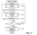
- FIG. 5 is a flowchart showing an example of fine water release processing.
- the control unit 50 executes moisture absorption control to cause the fine water generation cartridge 30 (fine water discharge element 34) to adsorb moisture (S100), and determines whether the first time has elapsed (S110). ).
- the first time is a time predetermined as an execution time of moisture absorption control, and is set to a time of several minutes, such as 5 minutes, for example. If the control unit 50 determines that the first time has not elapsed, the process returns to S100.
- the control unit 50 determines that the first time has elapsed, it executes moisture release control to release the adsorbed moisture as fine water from the fine water generation cartridge 30 (fine water release element 34) (S120), It is determined whether the second time has elapsed (S130).
- the second time is a time predetermined as the execution time of the moisture release control, and is set to a time of several minutes, such as two minutes, which is shorter than the first time, for example. Note that the second time may be the same time as the first time. If the control unit 50 determines that the second time has not elapsed, the process returns to S120.
- control unit 50 determines whether it is time to stop the fine water release process (S140), and when it determines that it is not the time to stop, it returns to S100 and executes moisture absorption control. In this way, the control unit 50 performs the moisture absorption control in S100 and the moisture release control in S120 while switching between them.
- the control unit 50 allows the user to perform a stop operation. If this is the case, it is determined in S140 that it is time to stop.
- control unit 50 determines that it is time to stop, it stops energizing the fine water generation cartridge 30 and the fan 40 (S150), and ends the fine water discharge process.
- the details of the moisture absorption control in S100 and the moisture release control in S120 will be described below.
- the moisture absorption control in S100 is executed based on the flowchart in FIG.
- the control unit 50 first rotates the fan 40 at high speed so as to blow air at a relatively high wind speed (S200), and the temperature of the fine water emitting element 34 (base material 35) detected by the internal temperature sensor 57 is the first. It is determined whether the temperature is below the temperature (S210).
- the first temperature is set to be higher than the environmental temperature, which is the temperature around the fine water discharge device 10.
- the first temperature is preset at, for example, 50° C., which is a temperature that normally does not fall below the environmental temperature.
- the control unit 50 determines that the temperature of the fine water emitting element 34 is equal to or lower than the first temperature, the control unit 50 sets the first energization state (weak energization state) in which a relatively small current (small current) is caused to flow to the base material 35.
- a control signal is output to the energizing circuit 38 to energize the fine water generation cartridge 30 with a small current (S220).
- the control unit 50 determines that the temperature of the fine water emitting element 34 is not lower than the first temperature, it skips S220. Note that when the moisture absorption control is executed immediately after the start of the fine water release process, the control unit 50 normally determines that the temperature is below the first temperature in S210 and energizes in S220. Therefore, the temperature of the fine water emitting element 34 increases.
- the control unit 50 determines whether the temperature of the fine water emitting element 34 detected by the internal temperature sensor 57 has reached the second temperature (S230).
- the second temperature is predetermined as a temperature several degrees Celsius higher than the first temperature, for example, 55 degrees Celsius.
- the control unit 50 determines that the temperature of the fine water emitting element 34 has not reached the second temperature, it ends the moisture absorption control.
- the control unit 50 determines that the temperature of the fine water discharge element 34 has reached the second temperature, it stops energizing the fine water generation cartridge 30 and blows air at a relatively slow wind speed (predetermined wind speed).
- the fan 40 is rotated at a low speed (S240), and the moisture absorption control is ended.
- the control section 50 stops energizing the fine water generation cartridge 30 and rotates the fan 40 at a low speed. Therefore, even if energization is started to the fine water generation cartridge 30 in S220, it is possible to suppress the temperature of the fine water emitting element 34 from rising above the second temperature.
- the moisture release control in S120 is executed based on the flowchart in FIG.
- the control unit 50 first rotates the fan 40 at a low speed so as to blow air at a relatively slow wind speed (predetermined wind speed) (S300).
- predetermined wind speed predetermined wind speed
- the control unit 50 only needs to rotate the fan 40 at a lower speed than in S200, and in this embodiment, the control unit 50 rotates the fan 40 at the same speed as in S240.
- the control unit 50 determines whether the temperature of the fine water emitting element 34 detected by the internal temperature sensor 57 is equal to or lower than the third temperature (S310).
- the third temperature is predetermined as a temperature higher than the above-mentioned second temperature, such as 65° C., for example.
- the control unit 50 determines that the temperature of the fine water emitting element 34 is equal to or lower than the third temperature
- the control unit 50 sets the second energization state (strong energization state) to flow a relatively large current (large current) to the base material 35.
- a control signal is output to the energization circuit 38 to energize the fine water generation cartridge 30 with a large current (S320). That is, in the moisture release control, the control unit 50 causes the fine water generation cartridge 30 to pass a current larger than that in the moisture absorption control, thereby raising the temperature of the fine water release element 34 higher than in the moisture absorption state. Further, if the control unit 50 determines that the temperature of the fine water emitting element 34 is not lower than the third temperature, it skips S320.
- the control unit 50 determines in S310 that the third temperature is lower than the third temperature, and in S320, a large current is applied to the fine water generation cartridge 30. energize.
- the control unit 50 determines whether the temperature of the fine water emitting element 34 detected by the internal temperature sensor 57 has reached the fourth temperature (S330).
- the fourth temperature is predetermined as a temperature higher than the third temperature by several degrees Celsius to ten degrees Celsius, for example, 75 degrees Celsius.
- the control unit 50 determines that the temperature of the fine water emitting element 34 has not reached the fourth temperature, it ends the moisture release control.
- the control unit 50 determines that the temperature of the fine water emitting element 34 has reached the fourth temperature, it stops energizing the fine water generating cartridge 30 (S340) and ends the moisture release control.
- the control unit 50 stops energizing the fine water generating cartridge 30. Thereby, it is possible to suppress the temperature of the fine water emitting element 34 from rising above the fourth temperature.
- the control unit 50 determines that the second time has elapsed in S130, and determines that it is not the stop timing in the subsequent S140, it switches to moisture absorption control in S100 (FIG. 5).
- the moisture absorption control since the control unit 50 rotates the fan 40 at high speed in S200, it is possible to quickly cool the fine water emitting element 34 whose temperature has risen to between the third temperature and the fourth temperature. Further, the control unit 50 rotates the fan 40 at high speed until the temperature of the fine water discharge element 34 decreases and reaches the second temperature, and when it is determined in S230 that the temperature of the fine water discharge element 34 has reached the second temperature. , the fan 40 is rotated at low speed in S240.
- the control unit 50 performs moisture absorption control between the first temperature and the second temperature (for example, 50°C to 55°C) and between the third temperature and the fourth temperature (for example, 65°C to 75°C). Execute while switching between moisture release control and moisture release control. Therefore, a temperature difference of approximately 10 to 20° C. occurs between the time of moisture absorption and the time of moisture release. If the temperature at the time of moisture absorption decreases by about 10 to 20 degrees Celsius from the temperature at the time of moisture release, the fine water release element 34 will appropriately change to the moisture absorption state and release fine water even if the temperature is higher than normal temperature, for example about 25 degrees Celsius. It becomes possible to absorb moisture.
- FIG. 8 is a schematic diagram of the conductive polymer film 36 in a hygroscopic state in a comparative example.
- FIG. 9 is a schematic diagram of the conductive polymer film 36 in a hygroscopic state in this embodiment.
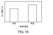
- FIG. 10 is an explanatory diagram showing an example of the relationship between the temperature during hygroscopicity and the ion current.
- no current is passed through the fine water generating cartridge 30 (substrate 35) in the hygroscopic control, and the hygroscopic control is performed when the fine water emitting element 34 (substrate 35) is at room temperature, for example, about 25°C.
- the hygroscopic control is performed when the fine water emitting element 34 is at a relatively high temperature, such as 50 to 55°C.
- the left bar graph in FIG. 10 shows the comparative example, and shows the ion current detected when, for example, the hygroscopic control is performed at room temperature of about 25°C and the hygroscopic control is performed at about 45°C.
- the right bar graph in FIG. 10 shows the present embodiment, and shows the ion current detected when, for example, the hygroscopic control is performed at a high temperature of about 55°C and the hygroscopic control is performed at about 67°C.
- the amount of fine water discharged was determined by passing the fine water discharged from the fine water discharge element 34 through a neutralizer to charge it, measuring the electrical mobility of the charged fine water with a differential mobility analyzer, classifying it, and measuring the current (charge) of fine water of 50 nanometers or less. A larger ion current indicates a larger amount of fine water discharged under moisture release control.
- the water particles W of adjacent sulfonic acid groups combine to form bulk water, and the nanochannel 36c is filled with water. It is thought that the bound water particles W are less likely to exist in a cluster state with a particle size of about 2 nanometers or less, and are less likely to be released as fine water in a moisture-releasing state. As a result, the amount of released fine water of 50 nanometers or less is reduced (see FIG. 10).
- the fine water release element 34 is brought to a high temperature state by moisture absorption control, so the shell (PSS 36b) contracts and at the same time, the nanochannel 36c becomes smaller.
- the shell (PSS 36b) contracts and at the same time, the nanochannel 36c becomes smaller.
- the number of sites that can adsorb water within the nanochannel 36c decreases, and the total amount of water that can be adsorbed decreases.
- the number of water particles W existing in a cluster state with a particle size of about 2 nanometers or less increases.
- the amount of fine water of 50 nanometers or less released is greater than that of the comparative example (see FIG.
- the PSS 36b of the shell further contracts.
- the release of fine water from within the nanochannels 36c is promoted by the temperature rise, contraction of the shell (PSS 36b), and the above-mentioned difference in water concentration between the surface and the inside of the element.
- the fine water discharge device 10 discharges fine water toward the skin, hair, etc. of the human body.
- the stratum corneum on the surface of the skin has minute gaps of about 20 to 50 nanometers or less. Therefore, if the particle size of the fine water is 50 nanometers or less, it is easy for the fine water to penetrate from the stratum corneum into the inside of the skin.
- the particle size of the fine water is 50 nanometers or less, it is easy for the fine water to penetrate into the inside of the hair.
- the fine water discharge device 10 of this embodiment makes it easier for water particles W to exist in a state of 50 nanometers or less when absorbing moisture, thereby promoting the discharge of fine water of 50 nanometers or less when releasing moisture, and improving the effect of penetrating the fine water into the skin and hair. This allows the fine water to fully penetrate the skin and hair, resulting in an improved moisturizing effect.
- the fine water discharge device 10 of the present embodiment described above performs moisture absorption control in which a small current is applied so that the fine water discharge element 34 enters the moisture absorption state, and the temperature of the fine water discharge element 34 is made higher than the temperature in the moisture absorption state.
- the moisture release control is performed by applying a large current to bring the moisture into the moisture release state.
- the amount of water adsorbed to the conductive polymer film 36 is controlled, the binding of water particles W is suppressed, and the total amount of water is It is possible to increase the adsorption ratio of water particles W that become fine water. Therefore, appropriate release of fine water can be promoted.
- control unit 50 starts applying a small current when the temperature of the fine water releasing element 34 is below the first temperature, and stops applying the current when the temperature is above the second temperature, so that the fine water is released. It is possible to prevent the temperature of the element 34 from becoming too high and being unable to absorb moisture.
- control unit 50 starts applying a large current when the temperature of the fine water emitting element 34 is below the third temperature, and stops applying the large current when the temperature is above the fourth temperature. It is possible to suppress excessive temperature rise while ensuring a temperature difference between the two and performing appropriate moisture absorption and desorption.
- control unit 50 rotates the fan 40 at low speed during moisture release control and rotates the fan 40 at high speed when starting moisture absorption control, the fine water release element 34 is cooled during moisture absorption control after moisture release control. can be quickly brought into a moisture-absorbing state.
- the PSS 36b of the shell contracts and suppresses the amount of water adsorbed in the nanochannels 36c, so that the total amount of water adsorbed is lower than that when adsorbed at room temperature. Although this decreases, the proportion of water particles W that becomes fine water increases.
- the PSS 36b of the shell further contracts, and fine water is released from within the nanochannel 36c due to the difference in water concentration between the element surface and the inside.
- the fine water discharge device 10 can absorb and release moisture by making the fine water discharge element 34 having the conductive polymer film 36 having a core-shell structure function more appropriately.
- the fan 40 is rotated at high speed in step S200 of the moisture absorption control, but it is usually not necessary to operate the fan 40 at high speed for cooling in the moisture absorption control immediately after the start of the fine water release process (first time). S200 may be omitted.
- the method is not limited to rotating the fan 40 at high speed under moisture absorption control, and the following method may be used.
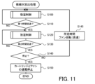
- FIG. 11 is a flowchart showing a modified example of fine water release processing.
- FIG. 12 is a flowchart showing moisture absorption control in a modified example. In the following modified examples, the same step numbers are given to the same processes as in the embodiment, and the description thereof will be omitted.
- the control unit 50 determines that it is not the stop timing in S140, it performs cooling control to rotate the fan 40 at high speed for a predetermined period of time (S145), and then performs cooling control in S100. Shift to moisture absorption control. That is, the fine water release process of the embodiment ( Figure 5) is different.
- the predetermined time in the cooling control in S145 is predetermined as the time required to bring the fine water discharge element 34, which has become relatively high temperature due to the moisture absorption control, to the temperature of the moisture absorption state.
- control unit 50 operates the fan 40 at high speed until it detects that the temperature of the fine water discharge element 34 has reached a temperature at which moisture is absorbed (for example, a second temperature or lower). After the rotation, the process may proceed to moisture absorption control in S100.
- the control unit 50 first rotates the fan 40 at a low speed so as to blow air at a relatively slow wind speed (predetermined wind speed) (S200B). Further, if the control unit 50 determines in S230 that the temperature of the fine water emitting element 34 has reached the second temperature, it stops the power supply to the fine water generating cartridge 30 (S240B), and ends the moisture absorption control. In this way, in the moisture absorption control of the modified example, the fan 40 is rotated at low speed when moisture absorption control is started, and the fan 40 is kept rotating at low speed without being stopped when moisture absorption control is ended.
- predetermined wind speed predetermined wind speed
- the fine water releasing element 34 can adsorb moisture in a period of about several seconds to several tens of seconds. Therefore, if the temperature of the fine water release element 34 reaches the second temperature during the first time (S110) during which the moisture absorption control is performed and moisture is adsorbed by the fine water release element 34, the moisture absorption control is performed. There is no need to provide cooling control (S145) between this and moisture release control.
- predetermined temperatures are used as the first to fourth temperatures, but the present invention is not limited to this, and temperatures set based on the environmental temperature, which is the temperature around the fine water discharge device 10 and the fine water generating cartridge 30, may be used.
- FIG. 13 is a schematic diagram of a modified fine water discharge device 10B. This fine water discharge device 10B is equipped with an environmental temperature sensor 58 that detects the environmental temperature, which is the temperature around the fine water discharge device 10. The control unit 50 may set the first to fourth temperatures based on the environmental temperature detected by the environmental temperature sensor 58.
- control unit 50 may set the first temperature by adding a temperature of several tens of degrees Celsius, such as 20°C to 30°C (first predetermined temperature) to the environmental temperature detected by the environmental temperature sensor 58, and set the second temperature by adding a temperature of several degrees Celsius to tens of degrees Celsius (second predetermined temperature) to the first temperature.
- the control unit 50 may also set the third temperature by adding a temperature of several tens of degrees Celsius to tens of degrees Celsius (third predetermined temperature) to the second temperature, and set the fourth temperature by adding a temperature of several degrees Celsius to tens of degrees Celsius (fourth predetermined temperature) to the third temperature.
- control unit 50 may selectively set the first to fourth temperatures based on the environmental temperature detected by the environmental temperature sensor 58. For example, the control unit 50 sets temperatures 1A, 2A, 3A, and 4A as the first temperature, second temperature, third temperature, and fourth temperature, respectively when the environmental temperature is low, and when the environmental temperature is high. In this case, temperature 1B, temperature 2B, temperature 3B, and temperature 4B are set respectively. Each temperature is defined as temperature 1A, temperature 1B, temperature 2A, temperature 2B, temperature 3A, temperature 3B, temperature 4A, temperature 4B from the lowest one, and is determined in advance and stored in a storage unit such as a ROM of the control unit 50. Bye. Further, the control unit 50 may change the settings of the first to fourth temperatures in accordance with changes in the environmental temperature during execution of the fine water release process.
- the fan 40 changes the wind speed in two stages, but the fan 40 is not limited to this, and the wind speed may be changed in three or more stages.
- control unit 50 terminates the passage of current when the second temperature is reached in moisture absorption control (when the temperature is equal to or higher than the second temperature), but this is not limited to the above and the amount of current flow may be reduced to suppress temperature rise. Also, the control unit 50 terminates the passage of current when the fourth temperature is reached in moisture release control (when the temperature is equal to or higher than the fourth temperature), but this is not limited to the above and the amount of current flow may be reduced to suppress temperature rise.
- the temperature of the fine water emitting element 34 is increased by energizing the base material 35, that is, an example in which electrical energy is supplied as energy. may be supplied, or both electrical energy and thermal energy may be supplied.
- the first energy is supplied to the fine water release element 34
- the second energy that makes the temperature higher than that in the moisture absorption control is supplied to the fine water release element 34.
- the type of energy supplied may be different from that for moisture release control.
- the first energy may be supplied from one supply section to the fine water discharge element 34, and in the moisture release control, the second energy may be supplied to the fine water discharge element 34 from two or more supply sections.
- the fine water discharge device 10 of the embodiment corresponds to the "fine water discharge device" of the present disclosure
- the fine water discharge element 34 corresponds to the "fine water discharge element”
- the control unit 50 corresponds to the "control unit”.
- Internal temperature sensor 57 corresponds to a "temperature sensor”.
- the fan 40 corresponds to the "air blower”.
- an example of the fine water discharge method of this indication is also made clear by demonstrating the operation
- the fine water emitting device (10) of the present disclosure includes a base material (35) and a conductive polymer film (36) provided on the base material (35), and a moisture absorption state in which water is adsorbed on the conductive polymer film (36), and a moisture release state in which the water adsorbed on the conductive polymer film (36) is released as fine water with a particle size of 50 nanometers or less.
- a changing microscopic water emitting element (34) for supplying energy to the microscopic water emitting element (34); and supplying first energy to bring the microscopic water emitting element (34) into the moisture absorbing state.
- the present invention is summarized as follows: a moisture release control that controls the supply section (38) to supply the second energy; and a control section (50) that executes the moisture release control.
- the fine water emitting device of the present disclosure includes moisture absorption control that supplies first energy that brings the fine water emitting element into a moisture absorbing state, and second energy that makes the fine water emitting element higher in temperature than the moisture absorbing state and brings the fine water releasing element into a moisture releasing state.
- the temperature of the fine water release element is made higher than in moisture absorption control which does not supply energy, so it is possible to control the amount of moisture adsorbed on the conductive polymer film. Therefore, it is possible to suppress the binding of water particles and increase the adsorption ratio of water particles that become fine water to the total amount of water adsorbed, so that release of fine water during moisture release control can be promoted.
- the control unit (50) also includes a temperature sensor (57) that detects the temperature of the fine water emitting element (34), and the control unit (50) is configured such that in the moisture absorption control, the temperature of the fine water emitting element (34) is set to a first temperature.
- the supply of the first energy is started in the following cases, and the supply of the first energy is stopped when the temperature of the fine water emitting element (34) is a second temperature higher than the first temperature.
- the supply unit (38) may also be controlled. This makes it possible to maintain the temperature of the fine water emitting element within an appropriate range during moisture absorption control, and to appropriately suppress the bonding of water particles inside the fine water emitting element.
- the control unit (50) starts supplying the second energy when the temperature of the fine water release element (34) is a third temperature higher than the second temperature or less
- the supply unit (38) may be controlled so as to stop supplying the second energy when the temperature of the fine water emitting element (34) is equal to or higher than a fourth temperature higher than the third temperature.
- the air blowing unit (40) is configured to blow air through the fine water emitting element (34) so that air circulates therethrough, and the control unit (50) controls the air blowing unit to blow air at a predetermined wind speed in the moisture release control. (40) to blow air at a faster wind speed than the predetermined wind speed when switching from the moisture release control to the moisture absorption control or before switching to the moisture absorption control. It can also be used as a thing. In this way, cooling of the fine water emitting element can be promoted, so that the fine water emitting element can be quickly changed to a moisture absorbing state after moisture release control.
- an environmental temperature sensor (58) that detects the environmental temperature may be provided, and the control section (50) may adjust the first energy according to the environmental temperature.
- the control unit (50) also includes an environmental temperature sensor (58) that detects an environmental temperature, and the control unit (50) sets the first temperature to a temperature obtained by adding a first predetermined temperature to the environmental temperature, and The second temperature may be set to a temperature obtained by adding a second predetermined temperature to the temperature.
- control unit (50) sets the third temperature to a temperature obtained by adding a third predetermined temperature to the second temperature, and sets the third temperature to a temperature obtained by adding a fourth predetermined temperature to the third temperature. It is also possible to set four temperatures.
- the correspondence relationship between the main elements of the embodiment and the main elements of the present disclosure described in the column of means for solving the problem is the same as the correspondence relationship between the main elements of the embodiment and the main elements of the present disclosure described in the column of means for solving the problem. Since this is an example for specifically explaining a mode for implementing the above, it is not intended to limit the elements of the present disclosure described in the column of means for solving the problems. In other words, the interpretation of the present disclosure described in the column of means to solve the problem should be made based on the description in that column, and the embodiments should be interpreted based on the book described in the column of means to solve the problem. This is just one specific example of disclosure.
- the present disclosure can be used in the technical field of emitting fine water from a fine water emitting element.
- Fine water release device 10B Fine water release device, 20 Duct, 21a Inlet, 21b Outlet, 30 Fine water generation cartridge, 32 Case, 34 Fine water release element (fine water generation element), 35 Base material, 36 Conductive polymer membrane , 36a PEDOT, 36b PSS, 36c nanochannel, 38 energizing circuit (supply section), 40 fan (blower section), 50 control section, 55 start switch, 56 air volume adjustment switch, 57 internal temperature sensor, 58 environmental temperature sensor, W water particles.
- Base material 36 Conductive polymer membrane , 36a PEDOT, 36b PSS, 36c nanochannel, 38 energizing circuit (supply section), 40 fan (blower section), 50 control section, 55 start switch, 56 air volume adjustment switch, 57 internal temperature sensor, 58 environmental temperature sensor, W water particles.
Landscapes
- Chemical & Material Sciences (AREA)
- Analytical Chemistry (AREA)
- Chemical Kinetics & Catalysis (AREA)
- Oil, Petroleum & Natural Gas (AREA)
- Engineering & Computer Science (AREA)
- General Chemical & Material Sciences (AREA)
- Organic Chemistry (AREA)
- Health & Medical Sciences (AREA)
- Dermatology (AREA)
- General Health & Medical Sciences (AREA)
- Drying Of Gases (AREA)
Abstract
This fine water releasing device is provided with: a base material; and an electroconductive polymer membrane provided on the base material. The fine water releasing device is also provided with: a fine water releasing element of which the state is changed between a moisture-absorbing state in which water in air is adsorbed onto the electroconductive polymer membrane and a moisture-releasing state in which the water adsorbed on the electroconductive polymer membrane is released as fine water having a particle diameter of 50 nanometers or less; a supply unit which supplies an energy to the fine water releasing element; and a control unit which performs both of moisture absorption for controlling the supply unit in such a manner that the supply unit supplies a first energy that makes the fine water releasing element in the moisture-absorbing state and moisture release control for controlling the supply unit in such a manner that the supply unit that increases the temperature of the fine water releasing element to a temperature higher than the temperature of the moisture-absorbing state so as to supply a second energy that makes the fine water releasing element in the moisture-releasing state.
Description
本開示は、微細水放出装置および微細水放出方法に関する。
The present disclosure relates to a fine water discharge device and a fine water discharge method.
従来、微細水放出装置としては、空気の流路を有する筒状のケースと、流路に配設され吸湿と放湿とを行う微細水放出素子を有する調湿部と、微細水放出素子の基材部に通電する通電部と、通電部を制御する制御部とを備えるものが提案されている(例えば、特許文献1参照)。この装置では、通電部により基材部を非通電状態とすることで微細水放出素子の温度低下によって空気中の水分を吸着させ、通電部により基材部を通電状態とすることで微細水放出素子の温度上昇によって微細水放出素子から微細水を放出させる。
Conventionally, a fine water emitting device has a cylindrical case having an air flow path, a humidity control section having a fine water emitting element arranged in the flow path to absorb and release moisture, and a humidity control part having a fine water emitting element that absorbs and releases moisture. A device has been proposed that includes an energizing section that energizes the base material section and a control section that controls the energizing section (for example, see Patent Document 1). In this device, moisture in the air is adsorbed by reducing the temperature of the fine water emitting element by de-energizing the base material using the current-carrying part, and releasing fine water by making the base material part energized by the current-carrying part. Fine water is released from the fine water emitting element as the temperature of the element increases.
上述した装置では、水分を吸着する際には、基材部を非通電状態とするだけで温度の制御は行っていない。このため、微細水放出素子への水分の吸着が促進されて水分量が過剰となり、微細水放出素子に吸湿された隣り合う水粒子同士が結合することがある。結合した水粒子は、微細水放出素子の温度が上昇しても、微細水として放出されにくくなると考えられる。
In the above-described device, when adsorbing moisture, the base material portion is simply de-energized and the temperature is not controlled. For this reason, adsorption of moisture onto the fine water emitting element is promoted, the amount of water becomes excessive, and adjacent water particles absorbed by the fine water emitting element may bond with each other. It is thought that the combined water particles become less likely to be released as fine water even if the temperature of the fine water emitting element increases.
本開示は、吸湿制御をより適切に行うことで放湿制御における微細水の放出を促すことを主目的とする。
The main purpose of the present disclosure is to promote release of fine water in moisture release control by performing moisture absorption control more appropriately.
本開示は、上述の主目的を達成するために以下の手段を採った。
The present disclosure has taken the following measures to achieve the above-mentioned main objective.
本開示の微細水放出装置は、
基材と、前記基材に設けられた導電性高分子膜とを有し、空気中の水分を前記導電性高分子膜に吸着する吸湿状態と前記導電性高分子膜に吸着した水分を粒径が50ナノメートル以下の微細水として放出する放湿状態とに変化する微細水放出素子と、
前記微細水放出素子にエネルギを供給する供給部と、
前記微細水放出素子を前記吸湿状態とする第1エネルギを供給するように前記供給部を制御する吸湿制御と、前記微細水放出素子の温度を前記吸湿状態の温度より高くして前記微細水放出素子を前記放湿状態とする第2エネルギを供給するように前記供給部を制御する放湿制御と、を実行する制御部と、
を備えることを要旨とする。 The fine water emitting device of the present disclosure includes:
The conductive polymer film has a base material and a conductive polymer film provided on the base material, and has a hygroscopic state in which moisture in the air is adsorbed to the conductive polymer film and the moisture adsorbed to the conductive polymer film is granulated. a fine water emitting element that changes into a moisture release state in which it releases fine water with a diameter of 50 nanometers or less;
a supply unit that supplies energy to the fine water emitting element;
moisture absorption control for controlling the supply unit to supply a first energy that brings the fine water release element into the moisture absorption state; and releasing the fine water by making the temperature of the fine water release element higher than the temperature in the moisture absorption state. a control unit that performs moisture release control that controls the supply unit to supply second energy that brings the element into the moisture release state;
The purpose is to have the following.
本開示の微細水放出装置は、微細水放出素子を吸湿状態とする第1エネルギを供給する吸湿制御と、吸湿状態の温度より高くして微細水放出素子を放湿状態とする第2エネルギを供給する放湿制御と、を実行する。吸湿制御でエネルギを供給することにより、エネルギを供給しない吸湿制御に比して微細水放出素子の温度を高くするから、導電性高分子膜に吸着される水分量を制御することができる。このため、水粒子の結合を抑えて、吸着される水分量全体に対して微細水となる水粒子の吸着割合を高めることができるから、放湿制御における微細水の放出を促すことができる。
The fine water emitting device of the present disclosure includes moisture absorption control that supplies first energy that brings the fine water emitting element into a moisture absorbing state, and second energy that makes the fine water emitting element higher in temperature than the moisture absorbing state and brings the fine water releasing element into a moisture releasing state. Supply moisture control and perform. By supplying energy with moisture absorption control, the temperature of the fine water release element is made higher than in moisture absorption control which does not supply energy, so it is possible to control the amount of moisture adsorbed on the conductive polymer film. Therefore, it is possible to suppress the binding of water particles and increase the adsorption ratio of water particles that become fine water to the total amount of water adsorbed, so that release of fine water during moisture release control can be promoted.
本開示の微細水放出方法は、
基材と、前記基材に設けられた導電性高分子膜とを有し、空気中の水分を前記導電性高分子膜に吸着する吸湿状態と前記導電性高分子膜に吸着した水分を粒径が50ナノメートル以下の微細水として放出する放湿状態とに変化する微細水放出素子から微細水を放出させる微細水放出方法であって、
前記微細水放出素子を前記吸湿状態とする第1エネルギを供給するように供給部を制御する吸湿制御ステップと、
前記微細水放出素子の温度を前記吸湿状態の温度より高くして前記微細水放出素子を前記放湿状態とする第2エネルギを供給するように前記供給部を制御する放湿制御ステップと、
を含むことを要旨とする。 The fine water release method of the present disclosure includes:
The conductive polymer film has a base material and a conductive polymer film provided on the base material, and has a hygroscopic state in which moisture in the air is adsorbed to the conductive polymer film, and a moisture absorbing state in which moisture in the air is adsorbed to the conductive polymer film, and the moisture adsorbed to the conductive polymer film is granulated. A fine water release method that releases fine water from a fine water release element that changes between a moisture releasing state and a moisture release state in which fine water is released as fine water with a diameter of 50 nanometers or less,
a moisture absorption control step of controlling a supply unit to supply first energy to bring the fine water release element into the moisture absorption state;
a moisture release control step of controlling the supply unit to supply a second energy that makes the temperature of the fine water release element higher than the temperature of the moisture absorption state and brings the fine water release element into the moisture release state;
The gist is to include the following.
本開示の微細水放出方法は、上述した微細水放出装置と同様に、水粒子の結合を抑えて、吸着される水分量全体に対して微細水となる水粒子の吸着割合を高めることができるから、放湿制御における微細水の放出を促すことができる。
The fine water discharge method of the present disclosure, like the fine water discharge device described above, can suppress the bonding of water particles and increase the adsorption ratio of water particles that become fine water to the total amount of water to be adsorbed. Therefore, it is possible to promote the release of fine water in moisture release control.
本開示の実施形態について図面を用いて説明する。図1は、微細水放出装置10の概略構成図である。図2は、微細水発生カートリッジ30の概略構成図である。図3は、微細水放出素子34の概略構成図である。図4は、導電性高分子膜36の模式図である。微細水放出装置10は、例えば人体(肌や毛髪など)に向けて微細水を放出する美容機器や医療機器として構成されている。微細水放出装置10は、図1に示すように、ダクト20と、微細水発生カートリッジ(微細水放出カートリッジ)30と、ファン40と、制御部50と、を備える。また、微細水放出装置10は、微細水放出装置10の運転を開始するためのスタートスイッチ55や、ファン40の風量を調節するための風量調節スイッチ56などの各種スイッチが設けられている。また、微細水放出装置10は、微細水発生カートリッジ30の内部の温度を検出する内部温度センサ57を備える。
Embodiments of the present disclosure will be described using the drawings. FIG. 1 is a schematic diagram of the fine water discharge device 10. As shown in FIG. FIG. 2 is a schematic diagram of the fine water generation cartridge 30. FIG. 3 is a schematic diagram of the fine water emitting element 34. As shown in FIG. FIG. 4 is a schematic diagram of the conductive polymer film 36. The fine water discharge device 10 is configured as, for example, a beauty device or a medical device that discharges fine water toward the human body (skin, hair, etc.). As shown in FIG. 1, the fine water discharge device 10 includes a duct 20, a fine water generation cartridge (fine water discharge cartridge) 30, a fan 40, and a control section 50. Further, the fine water discharge device 10 is provided with various switches such as a start switch 55 for starting the operation of the fine water discharge device 10 and an air volume adjustment switch 56 for adjusting the air volume of the fan 40. Further, the fine water discharge device 10 includes an internal temperature sensor 57 that detects the temperature inside the fine water generation cartridge 30.
ダクト20は、両端が開口した円筒状などの筒状部材であり、一端の吸入口21aと他端の排出口21bとを有する。ダクト20には、吸入口21a側からファン40、微細水発生カートリッジ30の順に配置されている。
The duct 20 is a cylindrical member such as a cylinder with both ends open, and has an inlet 21a at one end and an outlet 21b at the other end. In the duct 20, a fan 40 and a fine water generation cartridge 30 are arranged in this order from the suction port 21a side.
微細水発生カートリッジ30は、図2に示すように、ダクト20内に配置可能な外径の円筒状のケース32と、ケース32内に設けられた微細水放出素子(微細水発生素子)34とを備える。微細水放出素子34は、図3に示すように、基材35と、基材35の表面に形成された導電性高分子膜36とを備える。
As shown in FIG. 2, the fine water generating cartridge 30 includes a cylindrical case 32 with an outer diameter that can be placed inside the duct 20, and a fine water emitting element (fine water generating element) 34 provided inside the case 32. Equipped with. As shown in FIG. 3, the fine water emitting element 34 includes a base material 35 and a conductive polymer film 36 formed on the surface of the base material 35.
基材35は、ステンレス系金属や銅系金属などの金属材料、炭素材料、導電性セラミックス材料などの導電性を有する材料で形成されている。本実施形態では、アルミニウムが添加されたステンレス鋼の金属箔を用いる。なお、微細水放出素子34は、空気を流通可能であって基材35(導電性高分子膜36)の表面積ができるだけ大きくなるように、波板状やハニカム状、渦巻き状などに形成されている。基材35には、制御部50からの制御信号に基づいて作動する通電回路38(図1参照)が接続されている。通電回路38は、基材35へ比較的小さい小電流を通電する第1通電状態(弱通電状態)と、基材35へ比較的大きい大電流を通電する第2通電状態(強通電状態)と、基材35への通電を遮断する非通電状態とを切り替えるように構成されている。
The base material 35 is made of a conductive material such as a metal material such as a stainless steel metal or a copper metal, a carbon material, or a conductive ceramic material. In this embodiment, a stainless steel metal foil to which aluminum is added is used. Note that the fine water emitting element 34 is formed in a corrugated plate shape, a honeycomb shape, a spiral shape, etc. so that air can flow through it and the surface area of the base material 35 (conductive polymer film 36) is as large as possible. There is. An energization circuit 38 (see FIG. 1) that operates based on a control signal from the control section 50 is connected to the base material 35. The energization circuit 38 has a first energization state (weak energization state) in which a relatively small current is passed through the base material 35 and a second energization state (strong energization state) in which a relatively large large current is energized in the base material 35. , and a non-energized state in which power supply to the base material 35 is cut off.
導電性高分子膜36は、チオフェン系の導電性高分子などの導電性を有する高分子化合物で形成されている。本実施形態では、チオフェン系の導電性高分子のうち、PEDOT/PSS(ポリ(3,4-エチレンジオキシチオフェン)/ポリ(スチレンスルホン酸))により形成されている。例えば導電性高分子膜36は、PEDOTのコアと、水素結合可能な酸性官能基であるスルホン酸基のシェルとを有するコアシェル構造のPEDOT/PSSを水などの溶媒に分散させ、その分散液を基材35の外表面に塗布して乾燥させることによって形成される。このため、導電性高分子膜36は、図4に示すように、コアにPEDOT36aが存在し、コアを被覆するシェルに高分子材料のPSS36bが存在し、各粒子の間(シェルの間)に例えば2ナノメートル(nm)程度などのナノメートルサイズの流路であるナノチャンネル36cを形成する。このナノチャンネル36c内には、PSS36bのスルホン酸基が多く存在するため、導電性高分子膜36の表面に存在する水分は、表面の水分量が多く内部の水分量が少ない場合に、表面と内部の濃度差によってナノチャンネル36c内のスルホン酸基を伝って内部に移動する。これにより、導電性高分子膜36が水分としての水粒子Wを吸着する。
The conductive polymer film 36 is made of a conductive polymer compound such as a thiophene-based conductive polymer. In this embodiment, it is formed of PEDOT/PSS (poly(3,4-ethylenedioxythiophene)/poly(styrene sulfonic acid)) among thiophene-based conductive polymers. For example, the conductive polymer film 36 can be made by dispersing PEDOT/PSS, which has a core-shell structure having a core of PEDOT and a shell of a sulfonic acid group, which is an acidic functional group capable of hydrogen bonding, in a solvent such as water. It is formed by applying it to the outer surface of the base material 35 and drying it. Therefore, as shown in FIG. 4, in the conductive polymer film 36, PEDOT 36a exists in the core, PSS 36b made of polymer material exists in the shell covering the core, and between each particle (between the shells) For example, a nanochannel 36c, which is a nanometer-sized flow path of about 2 nanometers (nm), is formed. Since there are many sulfonic acid groups of PSS 36b in this nanochannel 36c, the water present on the surface of the conductive polymer film 36 is mixed with the surface when the amount of water on the surface is large and the amount of water inside is small. Due to the internal concentration difference, it moves inside through the sulfonic acid groups in the nanochannel 36c. As a result, the conductive polymer film 36 adsorbs water particles W as moisture.
また、内部に水分が吸着された状態で、表面の水分量が少なく内部の水分量が多い場合に、水分(水粒子W)は表面と内部の濃度差によってナノチャンネル36c内のスルホン酸基を伝って表面に移動する。これにより、導電性高分子膜36から水分が微細水として放出される。また、導電性高分子膜36の温度が上昇した状態では、濃度差のみで移動する場合に比して水分(微細水)の速やかな放出が促され、導電性高分子膜36の温度が低下した状態では、濃度差のみで移動する場合に比して水分の速やかな吸着が促される。このように、微細水発生カートリッジ30(微細水放出素子34)は、温度低下により導電性高分子膜36に空気中の水分を吸着する吸湿状態に変化し、吸着した水分を温度上昇により導電性高分子膜36から放出する放湿状態に変化する。なお、導電性高分子膜36の厚みは、必要な微細水の吸着量(放出量)に応じて適宜定めることができる。例えば、導電性高分子膜36の厚みが1~30マイクロメートルなどに形成された場合、数秒から数十秒程度の時間で、微細水の放出に十分な水分を吸着することができる。
In addition, when water is adsorbed inside and the amount of water on the surface is small and the amount of water inside is large, the water (water particles W) will absorb the sulfonic acid groups in the nanochannels 36c due to the difference in concentration between the surface and the inside. and move to the surface. As a result, water is released from the conductive polymer film 36 as fine water. In addition, when the temperature of the conductive polymer film 36 increases, the release of water (fine water) is promoted more quickly than when movement occurs only due to concentration difference, and the temperature of the conductive polymer film 36 decreases. In this state, moisture adsorption is promoted more quickly than when the water is moved only by concentration difference. In this way, the fine water generation cartridge 30 (fine water discharge element 34) changes to a hygroscopic state in which the conductive polymer membrane 36 adsorbs moisture in the air due to a temperature drop, and the adsorbed moisture becomes conductive due to a temperature rise. The state changes to a state where moisture is released from the polymer membrane 36. Note that the thickness of the conductive polymer film 36 can be determined as appropriate depending on the required adsorption amount (release amount) of fine water. For example, when the conductive polymer film 36 is formed to have a thickness of 1 to 30 micrometers, sufficient water can be adsorbed to release fine water in a few seconds to several tens of seconds.
また、微細水発生カートリッジ30は、微細水放出素子34の導電性高分子膜36から、水粒子の粒径が50ナノメートル以下、例えば粒径が1から2ナノメートル程度の無帯電の微細水(無帯電微細水粒子)を放出する。このような粒径となる理由は、ナノチャンネル36cのサイズが2ナノメートルまたはそれ以下のサイズであるため、導電性高分子膜36の温度上昇によるナノチャンネル36c内の水の運動性向上、圧力上昇により、ナノチャンネル36cから水分が飛び出す現象のためと考えられる。また、飛び出した後に水粒子同士が凝集しても、その粒径は50ナノメートル以下の範囲に分布するものとなっている。このような微細水発生カートリッジ30(導電性高分子膜36)の微細水発生の詳細な説明は、本願出願人のWO2020/054100および特開2019-018195号公報などに記載されているため、これ以上の詳細な説明は省略する。
The fine water generation cartridge 30 also generates uncharged fine water having a particle size of 50 nanometers or less, for example, about 1 to 2 nanometers, from the conductive polymer film 36 of the fine water discharge element 34. (uncharged fine water particles) are released. The reason for this particle size is that the size of the nanochannel 36c is 2 nanometers or less, so the increase in the temperature of the conductive polymer film 36 increases the mobility of the water in the nanochannel 36c, and the pressure This is thought to be due to a phenomenon in which moisture jumps out from the nanochannel 36c due to the rise. Further, even if the water particles aggregate after being ejected, the particle size is distributed within a range of 50 nanometers or less. A detailed explanation of the generation of fine water by the fine water generation cartridge 30 (conductive polymer membrane 36) is described in WO2020/054100 and Japanese Patent Application Laid-Open No. 2019-018195, etc. by the applicant. The detailed explanation above will be omitted.
ファン40は、所定回転方向の回転駆動により、吸入口21aからダクト20内に吸入した空気を、微細水発生カートリッジ30を通して、排出口21bから排出することができる。ファン40は、図示しないモータにより回転駆動し、制御部50によりPWM(Pulse Width Modulation)制御または電圧制御などによって制御される。なお、ファン40は、プロペラファンでもよいし、シロッコファンなどでもよい。
The fan 40 is rotationally driven in a predetermined rotational direction so that air sucked into the duct 20 from the suction port 21a can be discharged from the discharge port 21b through the fine water generation cartridge 30. The fan 40 is rotationally driven by a motor (not shown), and is controlled by a control unit 50 through PWM (Pulse Width Modulation) control, voltage control, or the like. Note that the fan 40 may be a propeller fan, a sirocco fan, or the like.
制御部50は、CPUを中心としたマイクロプロセッサとして構成されており、CPUの他にROMやRAM,タイマ,入出力ポートを備える。制御部50には、スタートスイッチ55からの操作信号や風量調節スイッチ56からの操作信号、微細水放出素子34(基材35)の温度など微細水発生カートリッジ30の内部温度を検出する内部温度センサ57からの検出信号などが入力ポートを介して入力される。なお、内部温度センサ57は、例えばサーミスタや熱電対などを用いることができる。また、制御部50からは、ファン40を回転駆動するモータへの駆動信号や通電回路38のスイッチへの駆動信号などが出力ポートを介して出力される。
The control unit 50 is configured as a microprocessor centered on a CPU, and includes a ROM, a RAM, a timer, and an input/output port in addition to the CPU. The control unit 50 includes an internal temperature sensor that detects an operation signal from the start switch 55, an operation signal from the air volume adjustment switch 56, and the internal temperature of the fine water generation cartridge 30, such as the temperature of the fine water discharge element 34 (base material 35). A detection signal from 57 is inputted via the input port. Note that the internal temperature sensor 57 can be, for example, a thermistor or a thermocouple. Further, the control unit 50 outputs a drive signal to the motor that rotationally drives the fan 40, a drive signal to the switch of the energization circuit 38, etc. through the output port.
次に、こうして構成された微細水放出装置10の動作について説明する。図5は微細水放出処理の一例を示すフローチャートである。この処理では、制御部50は、微細水発生カートリッジ30(微細水放出素子34)に水分を吸着させる吸湿制御を実行して(S100)、第1時間が経過したか否かを判定する(S110)。第1時間は、吸湿制御の実行時間として予め定められた時間であり、例えば5分などの数分程度の時間に定められている。制御部50は、第1時間が経過していないと判定するとS100に戻る。
Next, the operation of the fine water discharge device 10 configured in this way will be explained. FIG. 5 is a flowchart showing an example of fine water release processing. In this process, the control unit 50 executes moisture absorption control to cause the fine water generation cartridge 30 (fine water discharge element 34) to adsorb moisture (S100), and determines whether the first time has elapsed (S110). ). The first time is a time predetermined as an execution time of moisture absorption control, and is set to a time of several minutes, such as 5 minutes, for example. If the control unit 50 determines that the first time has not elapsed, the process returns to S100.
一方、制御部50は、第1時間が経過したと判定すると、吸着した水分を微細水として微細水発生カートリッジ30(微細水放出素子34)から放出させる放湿制御を実行して(S120)、第2時間が経過したか否かを判定する(S130)。第2時間は、放湿制御の実行時間として予め定められた時間であり、例えば第1時間より短い2分などの数分程度の時間に定められている。なお、第2時間は、第1時間と同じ時間でもよい。制御部50は、第2時間が経過していないと判定するとS120に戻る。
On the other hand, when the control unit 50 determines that the first time has elapsed, it executes moisture release control to release the adsorbed moisture as fine water from the fine water generation cartridge 30 (fine water release element 34) (S120), It is determined whether the second time has elapsed (S130). The second time is a time predetermined as the execution time of the moisture release control, and is set to a time of several minutes, such as two minutes, which is shorter than the first time, for example. Note that the second time may be the same time as the first time. If the control unit 50 determines that the second time has not elapsed, the process returns to S120.
制御部50は、第2時間が経過したと判定すると、微細水放出処理の停止タイミングであるか否かを判定し(S140)、停止タイミングでないと判定すると、S100に戻り吸湿制御を実行する。このように、制御部50は、S100の吸湿制御とS120の放湿制御とを切り替えながら実行する。なお、制御部50は、図示しないタイマで設定された微細水放出処理の実行時間に到達した場合や、吸湿制御および放湿制御の実行回数が所定回数に到達した場合、使用者により停止操作が行われた場合などに、S140で停止タイミングであると判定する。制御部50は、停止タイミングであると判定すると、微細水発生カートリッジ30とファン40への通電を停止して(S150)、微細水放出処理を終了する。以下、S100の吸湿制御とS120の放湿制御の詳細を説明する。
When the control unit 50 determines that the second time has elapsed, it determines whether it is time to stop the fine water release process (S140), and when it determines that it is not the time to stop, it returns to S100 and executes moisture absorption control. In this way, the control unit 50 performs the moisture absorption control in S100 and the moisture release control in S120 while switching between them. In addition, when the execution time of the fine water release process set by a timer (not shown) has been reached, or when the number of executions of moisture absorption control and moisture release control has reached a predetermined number of times, the control unit 50 allows the user to perform a stop operation. If this is the case, it is determined in S140 that it is time to stop. When the control unit 50 determines that it is time to stop, it stops energizing the fine water generation cartridge 30 and the fan 40 (S150), and ends the fine water discharge process. The details of the moisture absorption control in S100 and the moisture release control in S120 will be described below.
S100の吸湿制御は、図6のフローチャートに基づいて実行される。制御部50は、まず、比較的速い風速で送風するようにファン40を高速で回転させ(S200)、内部温度センサ57により検出される微細水放出素子34(基材35)の温度が第1温度以下であるか否かを判定する(S210)。第1温度は、微細水放出装置10の周囲の温度である環境温度よりも高い温度に定められている。本実施形態では、通常であれば環境温度を下回ることのない温度として、第1温度が例えば50℃などに予め定められている。
The moisture absorption control in S100 is executed based on the flowchart in FIG. The control unit 50 first rotates the fan 40 at high speed so as to blow air at a relatively high wind speed (S200), and the temperature of the fine water emitting element 34 (base material 35) detected by the internal temperature sensor 57 is the first. It is determined whether the temperature is below the temperature (S210). The first temperature is set to be higher than the environmental temperature, which is the temperature around the fine water discharge device 10. In the present embodiment, the first temperature is preset at, for example, 50° C., which is a temperature that normally does not fall below the environmental temperature.
制御部50は、微細水放出素子34の温度が第1温度以下であると判定すると、基材35へ比較的小さな電流(小電流)を流す第1通電状態(弱通電状態)となるように通電回路38に制御信号を出力して、微細水発生カートリッジ30に小さな電流を通電させる(S220)。また、制御部50は、微細水放出素子34の温度が第1温度以下でないと判定すると、S220をスキップする。なお、微細水放出処理の開始直後に吸湿制御が実行された場合、通常であれば制御部50はS210で第1温度以下と判定してS220で通電させる。このため、微細水放出素子34の温度が上昇する。
When the control unit 50 determines that the temperature of the fine water emitting element 34 is equal to or lower than the first temperature, the control unit 50 sets the first energization state (weak energization state) in which a relatively small current (small current) is caused to flow to the base material 35. A control signal is output to the energizing circuit 38 to energize the fine water generation cartridge 30 with a small current (S220). Further, if the control unit 50 determines that the temperature of the fine water emitting element 34 is not lower than the first temperature, it skips S220. Note that when the moisture absorption control is executed immediately after the start of the fine water release process, the control unit 50 normally determines that the temperature is below the first temperature in S210 and energizes in S220. Therefore, the temperature of the fine water emitting element 34 increases.
次に、制御部50は、内部温度センサ57により検出される微細水放出素子34の温度が第2温度に到達したか否かを判定する(S230)。第2温度は、第1温度よりも数℃程度高い温度として、例えば55℃などに予め定められている。制御部50は、微細水放出素子34の温度が第2温度に到達していないと判定すると、吸湿制御を終了する。一方、制御部50は、微細水放出素子34の温度が第2温度に到達したと判定すると、微細水発生カートリッジ30への通電を停止させると共に、比較的遅い風速(所定の風速)で送風するようにファン40を低速で回転させて(S240)、吸湿制御を終了する。即ち、制御部50は、微細水放出素子34の温度が第2温度以上になると、微細水発生カートリッジ30への通電を停止させてファン40を低速で回転させるのである。これにより、S220で微細水発生カートリッジ30に通電を開始させても、微細水放出素子34の温度が第2温度を超えて上昇するのを抑制することができる。
Next, the control unit 50 determines whether the temperature of the fine water emitting element 34 detected by the internal temperature sensor 57 has reached the second temperature (S230). The second temperature is predetermined as a temperature several degrees Celsius higher than the first temperature, for example, 55 degrees Celsius. When the control unit 50 determines that the temperature of the fine water emitting element 34 has not reached the second temperature, it ends the moisture absorption control. On the other hand, when the control unit 50 determines that the temperature of the fine water discharge element 34 has reached the second temperature, it stops energizing the fine water generation cartridge 30 and blows air at a relatively slow wind speed (predetermined wind speed). The fan 40 is rotated at a low speed (S240), and the moisture absorption control is ended. That is, when the temperature of the fine water discharge element 34 reaches or exceeds the second temperature, the control section 50 stops energizing the fine water generation cartridge 30 and rotates the fan 40 at a low speed. Thereby, even if energization is started to the fine water generation cartridge 30 in S220, it is possible to suppress the temperature of the fine water emitting element 34 from rising above the second temperature.
S120の放湿制御は、図7のフローチャートに基づいて実行される。制御部50は、まず、比較的遅い風速(所定の風速)で送風するようにファン40を低速で回転させる(S300)。S300では、制御部50は、S200よりも低速でファン40を回転させればよく、本実施形態ではS240と同じ速度でファン40を回転させる。次に、制御部50は、内部温度センサ57により検出される微細水放出素子34の温度が第3温度以下であるか否かを判定する(S310)。第3温度は、上述した第2温度よりも高い温度として、例えば65℃などに予め定められている。
The moisture release control in S120 is executed based on the flowchart in FIG. The control unit 50 first rotates the fan 40 at a low speed so as to blow air at a relatively slow wind speed (predetermined wind speed) (S300). In S300, the control unit 50 only needs to rotate the fan 40 at a lower speed than in S200, and in this embodiment, the control unit 50 rotates the fan 40 at the same speed as in S240. Next, the control unit 50 determines whether the temperature of the fine water emitting element 34 detected by the internal temperature sensor 57 is equal to or lower than the third temperature (S310). The third temperature is predetermined as a temperature higher than the above-mentioned second temperature, such as 65° C., for example.
制御部50は、微細水放出素子34の温度が第3温度以下であると判定すると、基材35へ比較的大きな電流(大電流)を流す第2通電状態(強通電状態)となるように通電回路38に制御信号を出力して、微細水発生カートリッジ30に大きな電流を通電させる(S320)。即ち、制御部50は、放湿制御では吸湿制御よりも大きな電流を微細水発生カートリッジ30に通電させて、微細水放出素子34の温度を吸湿状態よりも上昇させる。また、制御部50は、微細水放出素子34の温度が第3温度以下でないと判定すると、S320をスキップする。第3温度は第2温度より高い温度であるため、吸湿制御から放湿制御に切り替わった際に、制御部50はS310で第3温度以下と判定し、S320で微細水発生カートリッジ30に大きな電流を通電させる。
When the control unit 50 determines that the temperature of the fine water emitting element 34 is equal to or lower than the third temperature, the control unit 50 sets the second energization state (strong energization state) to flow a relatively large current (large current) to the base material 35. A control signal is output to the energization circuit 38 to energize the fine water generation cartridge 30 with a large current (S320). That is, in the moisture release control, the control unit 50 causes the fine water generation cartridge 30 to pass a current larger than that in the moisture absorption control, thereby raising the temperature of the fine water release element 34 higher than in the moisture absorption state. Further, if the control unit 50 determines that the temperature of the fine water emitting element 34 is not lower than the third temperature, it skips S320. Since the third temperature is higher than the second temperature, when switching from moisture absorption control to moisture release control, the control unit 50 determines in S310 that the third temperature is lower than the third temperature, and in S320, a large current is applied to the fine water generation cartridge 30. energize.
次に、制御部50は、内部温度センサ57により検出される微細水放出素子34の温度が第4温度に到達したか否かを判定する(S330)。第4温度は、第3温度よりも数℃程~十℃程度高い温度として、例えば75℃などに予め定められている。制御部50は、微細水放出素子34の温度が第4温度に到達してないと判定すると、放湿制御を終了する。一方、制御部50は、微細水放出素子34の温度が第4温度に到達したと判定すると、微細水発生カートリッジ30への通電を停止させて(S340)、放湿制御を終了する。即ち、制御部50は、微細水放出素子34の温度が第4温度以上になると、微細水発生カートリッジ30への通電を停止させるのである。これにより、微細水放出素子34の温度が第4温度を超えて上昇するのを抑制することができる。
Next, the control unit 50 determines whether the temperature of the fine water emitting element 34 detected by the internal temperature sensor 57 has reached the fourth temperature (S330). The fourth temperature is predetermined as a temperature higher than the third temperature by several degrees Celsius to ten degrees Celsius, for example, 75 degrees Celsius. When the control unit 50 determines that the temperature of the fine water emitting element 34 has not reached the fourth temperature, it ends the moisture release control. On the other hand, when the control unit 50 determines that the temperature of the fine water emitting element 34 has reached the fourth temperature, it stops energizing the fine water generating cartridge 30 (S340) and ends the moisture release control. That is, when the temperature of the fine water discharge element 34 reaches or exceeds the fourth temperature, the control unit 50 stops energizing the fine water generating cartridge 30. Thereby, it is possible to suppress the temperature of the fine water emitting element 34 from rising above the fourth temperature.
また、制御部50は、S130で第2時間が経過したと判定し、続くS140で停止タイミングでないと判定すると、S100(図5)の吸湿制御に切り替える。吸湿制御では、制御部50は、S200でファン40を高速で回転させるから、第3温度から第4温度の間の温度まで上昇した微細水放出素子34を速やかに冷却することができる。また、制御部50は、微細水放出素子34の温度が下がって第2温度に到達するまでファン40を高速回転させ、S230で微細水放出素子34の温度が第2温度に到達したと判定すると、S240でファン40を低速で回転させる。このように、制御部50は、第1温度から第2温度の間(例えば50℃~55℃)での吸湿制御と、第3温度から第4温度の間(例えば65℃~75℃)での放湿制御とを切り替えながら実行する。このため、吸湿時と放湿時の温度差として、約10~20℃程度の温度差が生じる。放湿時の温度から吸湿時の温度が約10~20℃程度低下すれば、例えば25℃程度の常温より高い温度であっても微細水放出素子34は吸湿状態に適切に変化して微細水を吸湿することが可能となる。
Further, if the control unit 50 determines that the second time has elapsed in S130, and determines that it is not the stop timing in the subsequent S140, it switches to moisture absorption control in S100 (FIG. 5). In the moisture absorption control, since the control unit 50 rotates the fan 40 at high speed in S200, it is possible to quickly cool the fine water emitting element 34 whose temperature has risen to between the third temperature and the fourth temperature. Further, the control unit 50 rotates the fan 40 at high speed until the temperature of the fine water discharge element 34 decreases and reaches the second temperature, and when it is determined in S230 that the temperature of the fine water discharge element 34 has reached the second temperature. , the fan 40 is rotated at low speed in S240. In this way, the control unit 50 performs moisture absorption control between the first temperature and the second temperature (for example, 50°C to 55°C) and between the third temperature and the fourth temperature (for example, 65°C to 75°C). Execute while switching between moisture release control and moisture release control. Therefore, a temperature difference of approximately 10 to 20° C. occurs between the time of moisture absorption and the time of moisture release. If the temperature at the time of moisture absorption decreases by about 10 to 20 degrees Celsius from the temperature at the time of moisture release, the fine water release element 34 will appropriately change to the moisture absorption state and release fine water even if the temperature is higher than normal temperature, for example about 25 degrees Celsius. It becomes possible to absorb moisture.
ここで、図8は、比較例における吸湿状態の導電性高分子膜36の模式図である。図9は、本実施形態における吸湿状態の導電性高分子膜36の模式図である。図10は、吸湿時温度とイオン電流の関係の一例を示す説明図である。比較例は、吸湿制御において微細水発生カートリッジ30(基材35)に電流を流さないものであり、微細水放出素子34(基材35)が例えば25℃程度の常温の状態で吸湿制御が実行される。本実施形態は、上述したように、微細水放出素子34が50~55℃などの比較的高温の状態で吸湿制御が実行される。図10の左の棒グラフは、比較例の場合を示し、例えば吸湿制御を約25℃の常温で実行し放湿制御を約45℃で実行した場合に検出されたイオン電流を示す。また、図10の右の棒グラフは、本実施形態の場合を示し、例えば吸湿制御を約55℃の高温で実行し放湿制御を約67℃で実行した場合に検出されたイオン電流を示す。なお、微細水放出量は、微細水放出素子34から放出された微細水を中和器に通して帯電させ、帯電した微細水の電気移動度を微分型電気移動度測定装置(Differential Mobility Analyzer)で測定して分級し、50ナノメートル以下の微細水の電流(電荷)を測定することにより求めた。イオン電流が大きいほど、放湿制御での微細水放出量が多いことを示す。
Here, FIG. 8 is a schematic diagram of the conductive polymer film 36 in a hygroscopic state in a comparative example. FIG. 9 is a schematic diagram of the conductive polymer film 36 in a hygroscopic state in this embodiment. FIG. 10 is an explanatory diagram showing an example of the relationship between the temperature during hygroscopicity and the ion current. In the comparative example, no current is passed through the fine water generating cartridge 30 (substrate 35) in the hygroscopic control, and the hygroscopic control is performed when the fine water emitting element 34 (substrate 35) is at room temperature, for example, about 25°C. In this embodiment, as described above, the hygroscopic control is performed when the fine water emitting element 34 is at a relatively high temperature, such as 50 to 55°C. The left bar graph in FIG. 10 shows the comparative example, and shows the ion current detected when, for example, the hygroscopic control is performed at room temperature of about 25°C and the hygroscopic control is performed at about 45°C. The right bar graph in FIG. 10 shows the present embodiment, and shows the ion current detected when, for example, the hygroscopic control is performed at a high temperature of about 55°C and the hygroscopic control is performed at about 67°C. The amount of fine water discharged was determined by passing the fine water discharged from the fine water discharge element 34 through a neutralizer to charge it, measuring the electrical mobility of the charged fine water with a differential mobility analyzer, classifying it, and measuring the current (charge) of fine water of 50 nanometers or less. A larger ion current indicates a larger amount of fine water discharged under moisture release control.
図8に示すように、比較例では、ナノチャンネル36c内に水を吸着できるサイトが多いため比較的多くの水分を吸着する。このため、隣り合うスルホン酸基同士の水粒子Wが結合してバルク水となり、ナノチャンネル36cが水分で埋まってしまうと考えられる。結合した水粒子Wは、粒径が2ナノメートル以下程度のクラスタ状態で存在しにくくなり、放湿状態において微細水として放出されにくくなると考えられる。この結果、50ナノメートル以下の微細水の放出量が少なくなる(図10参照)。
As shown in FIG. 8, in the comparative example, there are many sites that can adsorb water within the nanochannel 36c, so a relatively large amount of water is adsorbed. Therefore, it is considered that the water particles W of adjacent sulfonic acid groups combine to form bulk water, and the nanochannel 36c is filled with water. It is thought that the bound water particles W are less likely to exist in a cluster state with a particle size of about 2 nanometers or less, and are less likely to be released as fine water in a moisture-releasing state. As a result, the amount of released fine water of 50 nanometers or less is reduced (see FIG. 10).
一方、図9に示すように、本実施形態では、吸湿制御で微細水放出素子34が高温状態となるため、シェル(PSS36b)が収縮し、同時にナノチャンネル36cが小さくなる。比較例に比して、ナノチャンネル36c内に水を吸着できるサイトが減少し、吸着できる全体の水分量が減少すると考えられる。一方で、隣り合う水粒子Wの結合も行われにくいため、粒径が2ナノメートル以下程度のクラスタ状態で存在する水粒子Wが増えると考えられる。この結果、放湿状態において、比較例よりも50ナノメートル以下の微細水の放出量が多くなる(図10参照)。なお、図示は省略するが、放湿状態において微細水放出素子34の温度がさらに上昇すると、シェルのPSS36bがさらに収縮する。放湿制御では、その温度上昇と、シェル(PSS36b)の収縮と、上述した素子表面と内部との水分濃度差とによって、ナノチャンネル36c内から微細水の放出が促される。
On the other hand, as shown in FIG. 9, in this embodiment, the fine water release element 34 is brought to a high temperature state by moisture absorption control, so the shell (PSS 36b) contracts and at the same time, the nanochannel 36c becomes smaller. Compared to the comparative example, it is thought that the number of sites that can adsorb water within the nanochannel 36c decreases, and the total amount of water that can be adsorbed decreases. On the other hand, since it is difficult for adjacent water particles W to bond, it is thought that the number of water particles W existing in a cluster state with a particle size of about 2 nanometers or less increases. As a result, in the moisture release state, the amount of fine water of 50 nanometers or less released is greater than that of the comparative example (see FIG. 10). Although not shown, when the temperature of the fine water emitting element 34 further increases in the moisture releasing state, the PSS 36b of the shell further contracts. In the moisture release control, the release of fine water from within the nanochannels 36c is promoted by the temperature rise, contraction of the shell (PSS 36b), and the above-mentioned difference in water concentration between the surface and the inside of the element.
ここで、微細水放出装置10は、人体の肌や毛髪などに向けて微細水を放出するものである。肌(皮膚)の表面の角質層には、20~50ナノメートル程度以下の微細な隙間がある。このため、微細水は、粒径が50ナノメートル以下であれば角質層から肌の内部に浸透しやすくなる。毛髪についても同様に、毛髪表面のキューティクルに微細な隙間がある。このため、微細水は、粒径が50ナノメートル以下であれば毛髪の内部に浸透しやすくなる。本実施形態の微細水放出装置10は、比較例に比して、吸湿時に水粒子Wを50ナノメートル以下の状態で存在しやすくすることで、放湿時に50ナノメートル以下の微細水の放出を促して、微細水を肌や毛髪に浸透させる効果を高めることができる。これにより、微細水を肌や毛髪に十分に浸透させて保湿性の向上効果をもたらすことができる。
Here, the fine water discharge device 10 discharges fine water toward the skin, hair, etc. of the human body. The stratum corneum on the surface of the skin (skin) has minute gaps of about 20 to 50 nanometers or less. Therefore, if the particle size of the fine water is 50 nanometers or less, it is easy for the fine water to penetrate from the stratum corneum into the inside of the skin. Similarly, for hair, there are minute gaps in the cuticle on the surface of the hair. Therefore, if the particle size of the fine water is 50 nanometers or less, it is easy for the fine water to penetrate into the inside of the hair. Compared to the comparative example, the fine water discharge device 10 of this embodiment makes it easier for water particles W to exist in a state of 50 nanometers or less when absorbing moisture, thereby promoting the discharge of fine water of 50 nanometers or less when releasing moisture, and improving the effect of penetrating the fine water into the skin and hair. This allows the fine water to fully penetrate the skin and hair, resulting in an improved moisturizing effect.
以上説明した本実施形態の微細水放出装置10では、微細水放出素子34を吸湿状態とするように小電流を通電する吸湿制御と、微細水放出素子34の温度を吸湿状態の温度より高くして放湿状態とするように大電流を通電する放湿制御とを実行する。これにより、吸湿制御で微細水放出素子34に通電しない場合に比して、導電性高分子膜36に吸着される水分量を制御して水粒子Wの結合を抑え、水分量全体に対して微細水となる水粒子Wの吸着割合を高めることができる。このため、微細水の適切な放出を促すことができる。
The fine water discharge device 10 of the present embodiment described above performs moisture absorption control in which a small current is applied so that the fine water discharge element 34 enters the moisture absorption state, and the temperature of the fine water discharge element 34 is made higher than the temperature in the moisture absorption state. The moisture release control is performed by applying a large current to bring the moisture into the moisture release state. As a result, the amount of water adsorbed to the conductive polymer film 36 is controlled, the binding of water particles W is suppressed, and the total amount of water is It is possible to increase the adsorption ratio of water particles W that become fine water. Therefore, appropriate release of fine water can be promoted.
また、制御部50は、吸湿制御では、微細水放出素子34の温度が第1温度以下の場合に小電流の通電を開始し、第2温度以上の場合に通電を停止するから、微細水放出素子34の温度が高くなりすぎて吸湿できなくなるのを抑制することができる。
In addition, in the moisture absorption control, the control unit 50 starts applying a small current when the temperature of the fine water releasing element 34 is below the first temperature, and stops applying the current when the temperature is above the second temperature, so that the fine water is released. It is possible to prevent the temperature of the element 34 from becoming too high and being unable to absorb moisture.
また、制御部50は、放湿制御では、微細水放出素子34の温度が第3温度以下の場合に大電流の通電を開始し、第4温度以上の場合に通電を停止するから、吸湿制御との温度差を確保して適切な吸放湿を行いつつ過剰な温度上昇を抑制することができる。
In addition, in the moisture release control, the control unit 50 starts applying a large current when the temperature of the fine water emitting element 34 is below the third temperature, and stops applying the large current when the temperature is above the fourth temperature. It is possible to suppress excessive temperature rise while ensuring a temperature difference between the two and performing appropriate moisture absorption and desorption.
また、制御部50は、放湿制御ではファン40を低速で回転させ、吸湿制御を開始する際にファン40を高速で回転させるから、放湿制御後の吸湿制御において微細水放出素子34の冷却を促して速やかに吸湿状態とすることができる。
Moreover, since the control unit 50 rotates the fan 40 at low speed during moisture release control and rotates the fan 40 at high speed when starting moisture absorption control, the fine water release element 34 is cooled during moisture absorption control after moisture release control. can be quickly brought into a moisture-absorbing state.
また、微細水放出素子34は、吸湿状態において、シェルのPSS36bが収縮しナノチャンネル36c内に吸着される水分量を抑制することで、常温で吸着する場合に比して、全体の水分吸着量は減少するものの微細水となる水粒子Wの割合が高まる。微細水放出素子34は、放湿状態において、シェルのPSS36bがさらに収縮し、素子表面と内部との水分濃度差によりナノチャンネル36c内から微細水を放出する。これにより、微細水放出装置10は、コアシェル構造の導電性高分子膜36を有する微細水放出素子34をより適切に機能させて吸湿と放湿とを行うことができる。
In addition, in the micro water release element 34, in the moisture absorption state, the PSS 36b of the shell contracts and suppresses the amount of water adsorbed in the nanochannels 36c, so that the total amount of water adsorbed is lower than that when adsorbed at room temperature. Although this decreases, the proportion of water particles W that becomes fine water increases. In the moisture release state of the fine water releasing element 34, the PSS 36b of the shell further contracts, and fine water is released from within the nanochannel 36c due to the difference in water concentration between the element surface and the inside. Thereby, the fine water discharge device 10 can absorb and release moisture by making the fine water discharge element 34 having the conductive polymer film 36 having a core-shell structure function more appropriately.
実施形態では、吸湿制御のS200でファン40を高速で回転させたが、微細水放出処理の開始直後(初回)の吸湿制御では、通常は高速でファン40を作動させて冷却する必要はないのでS200を省略してもよい。あるいは、吸湿制御でファン40を高速で回転させるものに限られず、以下のようにしてもよい。図11は、変形例の微細水放出処理を示すフローチャートである。図12は、変形例の吸湿制御を示すフローチャートである。以下の変形例では、実施形態と同じ処理には同じステップ番号を付して説明を省略する。
In the embodiment, the fan 40 is rotated at high speed in step S200 of the moisture absorption control, but it is usually not necessary to operate the fan 40 at high speed for cooling in the moisture absorption control immediately after the start of the fine water release process (first time). S200 may be omitted. Alternatively, the method is not limited to rotating the fan 40 at high speed under moisture absorption control, and the following method may be used. FIG. 11 is a flowchart showing a modified example of fine water release processing. FIG. 12 is a flowchart showing moisture absorption control in a modified example. In the following modified examples, the same step numbers are given to the same processes as in the embodiment, and the description thereof will be omitted.
図11の変形例の微細水放出処理では、制御部50は、S140で停止タイミングでないと判定すると、所定時間に亘りファン40を高速で回転させる冷却制御を実施してから(S145)、S100の吸湿制御に移行する。即ち、放湿制御から吸湿制御に切り替わる前に所定時間に亘りファン40を高速で回転させて微細水発生カートリッジ30(微細水放出素子34)を冷却させる点で、実施形態の微細水放出処理(図5)と異なる。S145の冷却制御における所定時間は、吸湿制御で比較的高温となった微細水放出素子34を、吸湿状態の温度とするのに必要な時間として予め定められているものとする。なお、制御部50は、内部温度センサ57の検出温度に基づいて、微細水放出素子34の温度が吸湿状態の温度(例えば第2温度以下)となったことを検出するまでファン40を高速で回転させてから、S100の吸湿制御に移行してもよい。
In the fine water release process of the modified example of FIG. 11, when the control unit 50 determines that it is not the stop timing in S140, it performs cooling control to rotate the fan 40 at high speed for a predetermined period of time (S145), and then performs cooling control in S100. Shift to moisture absorption control. That is, the fine water release process of the embodiment ( Figure 5) is different. The predetermined time in the cooling control in S145 is predetermined as the time required to bring the fine water discharge element 34, which has become relatively high temperature due to the moisture absorption control, to the temperature of the moisture absorption state. Note that, based on the temperature detected by the internal temperature sensor 57, the control unit 50 operates the fan 40 at high speed until it detects that the temperature of the fine water discharge element 34 has reached a temperature at which moisture is absorbed (for example, a second temperature or lower). After the rotation, the process may proceed to moisture absorption control in S100.
図12の変形例の吸湿制御では、制御部50は、まず比較的遅い風速(所定の風速)で送風するようにファン40を低速で回転させる(S200B)。また、制御部50は、S230で微細水放出素子34の温度が第2温度に到達したと判定すると、微細水発生カートリッジ30への通電を停止させて(S240B)、吸湿制御を終了する。このように、変形例の吸湿制御では、吸湿制御を開始する際にファン40を低速で回転させ、吸湿制御を終了する際にファン40を停止させずに低速で回転させたままとする。
In the moisture absorption control of the modified example of FIG. 12, the control unit 50 first rotates the fan 40 at a low speed so as to blow air at a relatively slow wind speed (predetermined wind speed) (S200B). Further, if the control unit 50 determines in S230 that the temperature of the fine water emitting element 34 has reached the second temperature, it stops the power supply to the fine water generating cartridge 30 (S240B), and ends the moisture absorption control. In this way, in the moisture absorption control of the modified example, the fan 40 is rotated at low speed when moisture absorption control is started, and the fan 40 is kept rotating at low speed without being stopped when moisture absorption control is ended.
この変形例では、吸湿制御を開始する前にファン40を高速で所定時間回転させることで、微細水放出素子34の冷却を促すことができる。このため、吸湿制御を開始する際には微細水放出素子34を吸湿状態の温度として、速やかに吸湿させることができる。また、微細水放出処理の開始直後に実行される吸湿制御においても、ファン40を低速で回転させることで、微細水放出素子34を第1温度から第2温度の間の温度に速やかに昇温させて、水粒子Wの結合を抑えた適切な吸湿を速やかに開始させることができる。
In this modification, by rotating the fan 40 at high speed for a predetermined period of time before starting moisture absorption control, cooling of the fine water emitting element 34 can be promoted. Therefore, when moisture absorption control is started, the temperature of the fine water release element 34 is brought to a moisture absorption state, so that moisture can be quickly absorbed. Also, in the moisture absorption control that is executed immediately after the start of the fine water discharge process, by rotating the fan 40 at low speed, the temperature of the fine water discharge element 34 is quickly raised to a temperature between the first temperature and the second temperature. As a result, appropriate moisture absorption can be started quickly while suppressing the binding of water particles W.
なお、吸湿制御において微細水放出素子34の温度が第2温度に到達した後、微細水放出素子34は数秒から数十秒程度の時間で水分を吸着し得る。このため、吸湿制御が実施される第1時間(S110)の間に微細水放出素子34の温度が第2温度に到達し、微細水放出素子34に水分が吸着される場合には、吸湿制御と放湿制御の間に、冷却制御(S145)を設ける必要はない。
Note that in the moisture absorption control, after the temperature of the fine water releasing element 34 reaches the second temperature, the fine water releasing element 34 can adsorb moisture in a period of about several seconds to several tens of seconds. Therefore, if the temperature of the fine water release element 34 reaches the second temperature during the first time (S110) during which the moisture absorption control is performed and moisture is adsorbed by the fine water release element 34, the moisture absorption control is performed. There is no need to provide cooling control (S145) between this and moisture release control.
実施形態では、第1~第4温度として予め定められた温度を用いたが、これに限られず、微細水放出装置10や微細水発生カートリッジ30の周囲の温度である環境温度に基づいて設定された温度を用いてもよい。図13は、変形例の微細水放出装置10Bの概略構成図である。この微細水放出装置10Bは、微細水放出装置10の周囲の温度である環境温度を検出する環境温度センサ58を備える。制御部50は、環境温度センサ58により検出された環境温度に基づいて第1~第4温度を設定すればよい。例えば制御部50は、環境温度センサ58により検出された環境温度に20℃~30℃などの数十℃程度の温度(第1の所定温度)を加えて第1温度を設定し、第1温度に数℃~十℃程度の温度(第2の所定温度)を加えて第2温度を設定してもよい。また、制御部50は、第2温度に十℃~十数℃程度の温度(第3の所定温度)を加えて第3温度を設定し、第3温度に数℃~十℃程度の温度(第4の所定温度)を加えて第4温度を設定してもよい。
In the embodiment, predetermined temperatures are used as the first to fourth temperatures, but the present invention is not limited to this, and temperatures set based on the environmental temperature, which is the temperature around the fine water discharge device 10 and the fine water generating cartridge 30, may be used. FIG. 13 is a schematic diagram of a modified fine water discharge device 10B. This fine water discharge device 10B is equipped with an environmental temperature sensor 58 that detects the environmental temperature, which is the temperature around the fine water discharge device 10. The control unit 50 may set the first to fourth temperatures based on the environmental temperature detected by the environmental temperature sensor 58. For example, the control unit 50 may set the first temperature by adding a temperature of several tens of degrees Celsius, such as 20°C to 30°C (first predetermined temperature) to the environmental temperature detected by the environmental temperature sensor 58, and set the second temperature by adding a temperature of several degrees Celsius to tens of degrees Celsius (second predetermined temperature) to the first temperature. The control unit 50 may also set the third temperature by adding a temperature of several tens of degrees Celsius to tens of degrees Celsius (third predetermined temperature) to the second temperature, and set the fourth temperature by adding a temperature of several degrees Celsius to tens of degrees Celsius (fourth predetermined temperature) to the third temperature.
また、制御部50は、環境温度センサ58により検出された環境温度に基づいて、第1~第4温度を選択的に設定してもよい。例えば、制御部50は、第1温度,第2温度,第3温度,第4温度として、環境温度が低い場合にそれぞれ温度1A,温度2A,温度3A,温度4Aを設定し、環境温度が高い場合にそれぞれ温度1B,温度2B,温度3B,温度4Bを設定する。各温度は、低い方から温度1A,温度1B,温度2A,温度2B,温度3A,温度3B,温度4A,温度4Bとし、予め定められて制御部50のROMなどの記憶部に記憶されていればよい。また、制御部50は、微細水放出処理の実行中に、環境温度の変化に応じて第1~第4温度の設定を変更してもよい。
Furthermore, the control unit 50 may selectively set the first to fourth temperatures based on the environmental temperature detected by the environmental temperature sensor 58. For example, the control unit 50 sets temperatures 1A, 2A, 3A, and 4A as the first temperature, second temperature, third temperature, and fourth temperature, respectively when the environmental temperature is low, and when the environmental temperature is high. In this case, temperature 1B, temperature 2B, temperature 3B, and temperature 4B are set respectively. Each temperature is defined as temperature 1A, temperature 1B, temperature 2A, temperature 2B, temperature 3A, temperature 3B, temperature 4A, temperature 4B from the lowest one, and is determined in advance and stored in a storage unit such as a ROM of the control unit 50. Bye. Further, the control unit 50 may change the settings of the first to fourth temperatures in accordance with changes in the environmental temperature during execution of the fine water release process.
実施形態では、ファン40が2段階に風速を変更するものを例示したが、これに限られず、3段階以上の複数段階に風速を変更してもよい。
In the embodiment, the fan 40 changes the wind speed in two stages, but the fan 40 is not limited to this, and the wind speed may be changed in three or more stages.
実施形態では、制御部50は、吸湿制御において第2温度に到達した場合(第2温度以上の場合)に通電を終了したが、これに限らず、温度上昇を抑制するように通電量を低下させてもよい。また、制御部50は、放湿制御において第4温度に到達した場合(第4温度以上の場合)に通電を終了したが、これに限られず、温度上昇を抑制するように通電量を低下させてもよい。
In the embodiment, the control unit 50 terminates the passage of current when the second temperature is reached in moisture absorption control (when the temperature is equal to or higher than the second temperature), but this is not limited to the above and the amount of current flow may be reduced to suppress temperature rise. Also, the control unit 50 terminates the passage of current when the fourth temperature is reached in moisture release control (when the temperature is equal to or higher than the fourth temperature), but this is not limited to the above and the amount of current flow may be reduced to suppress temperature rise.
実施形態では、基材35への通電により微細水放出素子34の温度を上昇させるもの即ちエネルギとして電気エネルギを供給するものを例示したが、これに限られず、熱源(供給部)からの熱エネルギを供給してもよいし、電気エネルギと熱エネルギとを両方供給してもよい。また、吸湿制御では第1エネルギを微細水放出素子34に供給し、放湿制御では吸湿制御よりも温度を高くするような第2エネルギを微細水放出素子34に供給すればよく、吸湿制御と放湿制御とで供給するエネルギの種類が異なっていてもよい。あるいは、吸湿制御では1の供給部から微細水放出素子34に第1エネルギを供給し、放湿制御では2以上の供給部から微細水放出素子34に第2エネルギを供給してもよい。
In the embodiment, an example is given in which the temperature of the fine water emitting element 34 is increased by energizing the base material 35, that is, an example in which electrical energy is supplied as energy. may be supplied, or both electrical energy and thermal energy may be supplied. Further, in the moisture absorption control, the first energy is supplied to the fine water release element 34, and in the moisture release control, the second energy that makes the temperature higher than that in the moisture absorption control is supplied to the fine water release element 34. The type of energy supplied may be different from that for moisture release control. Alternatively, in the moisture absorption control, the first energy may be supplied from one supply section to the fine water discharge element 34, and in the moisture release control, the second energy may be supplied to the fine water discharge element 34 from two or more supply sections.
実施形態の主要な要素と課題を解決するための手段の欄に記載した本開示の主要な要素との対応関係について説明する。実施形態の微細水放出装置10が本開示の「微細水放出装置」に相当し、微細水放出素子34が「微細水放出素子」に相当し、制御部50が「制御部」に相当する。内部温度センサ57が「温度センサ」に相当する。ファン40が「送風部」に相当する。なお、本実施形態では、微細水放出装置10の動作を説明することにより本開示の微細水放出方法の一例も明らかにしている。
The correspondence between the main elements of the embodiment and the main elements of the present disclosure described in the section of means for solving the problems will be explained. The fine water discharge device 10 of the embodiment corresponds to the "fine water discharge device" of the present disclosure, the fine water discharge element 34 corresponds to the "fine water discharge element", and the control unit 50 corresponds to the "control unit". Internal temperature sensor 57 corresponds to a "temperature sensor". The fan 40 corresponds to the "air blower". In addition, in this embodiment, an example of the fine water discharge method of this indication is also made clear by demonstrating the operation|movement of the fine water discharge device 10.
以上説明したように、本開示の微細水放出装置(10)は、基材(35)と、前記基材(35)に設けられた導電性高分子膜(36)とを有し、空気中の水分を前記導電性高分子膜(36)に吸着する吸湿状態と前記導電性高分子膜(36)に吸着した水分を粒径が50ナノメートル以下の微細水として放出する放湿状態とに変化する微細水放出素子(34)と、前記微細水放出素子(34)にエネルギを供給する供給部(38)と、前記微細水放出素子(34)を前記吸湿状態とする第1エネルギを供給するように前記供給部(38)を制御する吸湿制御と、前記微細水放出素子(34)の温度を前記吸湿状態の温度より高くして前記微細水放出素子(34)を前記放湿状態とする第2エネルギを供給するように前記供給部(38)を制御する放湿制御と、を実行する制御部(50)と、を備えることを要旨とする。
As explained above, the fine water emitting device (10) of the present disclosure includes a base material (35) and a conductive polymer film (36) provided on the base material (35), and a moisture absorption state in which water is adsorbed on the conductive polymer film (36), and a moisture release state in which the water adsorbed on the conductive polymer film (36) is released as fine water with a particle size of 50 nanometers or less. a changing microscopic water emitting element (34); a supply section (38) for supplying energy to the microscopic water emitting element (34); and supplying first energy to bring the microscopic water emitting element (34) into the moisture absorbing state. moisture absorption control for controlling the supply unit (38) so as to make the temperature of the fine water release element (34) higher than the temperature of the moisture absorption state to bring the fine water release element (34) into the moisture release state. The present invention is summarized as follows: a moisture release control that controls the supply section (38) to supply the second energy; and a control section (50) that executes the moisture release control.
本開示の微細水放出装置は、微細水放出素子を吸湿状態とする第1エネルギを供給する吸湿制御と、吸湿状態の温度より高くして微細水放出素子を放湿状態とする第2エネルギを供給する放湿制御と、を実行する。吸湿制御でエネルギを供給することにより、エネルギを供給しない吸湿制御に比して微細水放出素子の温度を高くするから、導電性高分子膜に吸着される水分量を制御することができる。このため、水粒子の結合を抑えて、吸着される水分量全体に対して微細水となる水粒子の吸着割合を高めることができるから、放湿制御における微細水の放出を促すことができる。
The fine water emitting device of the present disclosure includes moisture absorption control that supplies first energy that brings the fine water emitting element into a moisture absorbing state, and second energy that makes the fine water emitting element higher in temperature than the moisture absorbing state and brings the fine water releasing element into a moisture releasing state. Supply moisture control and perform. By supplying energy with moisture absorption control, the temperature of the fine water release element is made higher than in moisture absorption control which does not supply energy, so it is possible to control the amount of moisture adsorbed on the conductive polymer film. Therefore, it is possible to suppress the binding of water particles and increase the adsorption ratio of water particles that become fine water to the total amount of water adsorbed, so that release of fine water during moisture release control can be promoted.
また、前記微細水放出素子(34)の温度を検出する温度センサ(57)を備え、前記制御部(50)は、前記吸湿制御では、前記微細水放出素子(34)の温度が第1温度以下の場合に前記第1エネルギの供給を開始し、前記微細水放出素子(34)の温度が前記第1温度より高い第2温度以上の場合に前記第1エネルギの供給を停止するように前記供給部(38)を制御するものとしてもよい。こうすれば、吸湿制御において微細水放出素子の温度を適切な範囲に維持し、微細水放出素子の内部の水粒子の結合を適切に抑制することができる。
The control unit (50) also includes a temperature sensor (57) that detects the temperature of the fine water emitting element (34), and the control unit (50) is configured such that in the moisture absorption control, the temperature of the fine water emitting element (34) is set to a first temperature. The supply of the first energy is started in the following cases, and the supply of the first energy is stopped when the temperature of the fine water emitting element (34) is a second temperature higher than the first temperature. The supply unit (38) may also be controlled. This makes it possible to maintain the temperature of the fine water emitting element within an appropriate range during moisture absorption control, and to appropriately suppress the bonding of water particles inside the fine water emitting element.
また、前記制御部(50)は、前記放湿制御では、前記微細水放出素子(34)の温度が前記第2温度より高い第3温度以下の場合に前記第2エネルギの供給を開始し、前記微細水放出素子(34)の温度が前記第3温度より高い第4温度以上の場合に前記第2エネルギの供給を停止するように前記供給部(38)を制御するものとしてもよい。こうすれば、吸湿制御と放湿制御とにおける微細水放出素子の温度差によって、吸放湿を適切に切り替えることができる。また、微細水放出素子の過剰な温度上昇を抑えることができる。
Further, in the moisture release control, the control unit (50) starts supplying the second energy when the temperature of the fine water release element (34) is a third temperature higher than the second temperature or less, The supply unit (38) may be controlled so as to stop supplying the second energy when the temperature of the fine water emitting element (34) is equal to or higher than a fourth temperature higher than the third temperature. In this way, moisture absorption and release can be appropriately switched based on the temperature difference of the fine water release element between moisture absorption control and moisture release control. Moreover, excessive temperature rise of the fine water emitting element can be suppressed.
また、前記微細水放出素子(34)を空気が流通するように送風する送風部(40)を備え、前記制御部(50)は、前記放湿制御では所定の風速で送風するように前記送風部(40)を制御し、前記放湿制御から前記吸湿制御に切り替えた場合または前記吸湿制御に切り替える前に前記所定の風速よりも速い風速で送風するように前記送風部(40)を制御するものとしてもよい。こうすれば、微細水放出素子の冷却を促すことができるから、放湿制御の後に微細水放出素子を速やかに吸湿状態に変化させることができる。
The air blowing unit (40) is configured to blow air through the fine water emitting element (34) so that air circulates therethrough, and the control unit (50) controls the air blowing unit to blow air at a predetermined wind speed in the moisture release control. (40) to blow air at a faster wind speed than the predetermined wind speed when switching from the moisture release control to the moisture absorption control or before switching to the moisture absorption control. It can also be used as a thing. In this way, cooling of the fine water emitting element can be promoted, so that the fine water emitting element can be quickly changed to a moisture absorbing state after moisture release control.
また、環境温度を検出する環境温度センサ(58)を備え、前記制御部(50)は、前記環境温度に応じて前記第1エネルギを調節するものとしてもよい。
Furthermore, an environmental temperature sensor (58) that detects the environmental temperature may be provided, and the control section (50) may adjust the first energy according to the environmental temperature.
また、環境温度を検出する環境温度センサ(58)を備え、前記制御部(50)は、前記環境温度に第1の所定温度を加えた温度に前記第1温度を設定し、前記第1温度に第2の所定温度を加えた温度に前記第2温度を設定するものとしてもよい。
The control unit (50) also includes an environmental temperature sensor (58) that detects an environmental temperature, and the control unit (50) sets the first temperature to a temperature obtained by adding a first predetermined temperature to the environmental temperature, and The second temperature may be set to a temperature obtained by adding a second predetermined temperature to the temperature.
また、前記制御部(50)は、前記第2温度に第3の所定温度を加えた温度に前記第3温度を設定し、前記第3温度に第4の所定温度を加えた温度に前記第4温度を設定するものとしてもよい。
Further, the control unit (50) sets the third temperature to a temperature obtained by adding a third predetermined temperature to the second temperature, and sets the third temperature to a temperature obtained by adding a fourth predetermined temperature to the third temperature. It is also possible to set four temperatures.
本明細書では、出願当初の請求項4において「請求項1または2に記載の微細水放出装置」を「請求項1ないし3のいずれか1項に記載の微細水放出装置」に変更した技術思想も開示されている。
In this specification, a technology in which "fine water discharge device according to claim 1 or 2" in claim 4 originally filed is changed to "fine water discharge device according to any one of claims 1 to 3" Thoughts are also disclosed.
なお、実施形態の主要な要素と課題を解決するための手段の欄に記載した本開示の主要な要素との対応関係は、実施形態が課題を解決するための手段の欄に記載した本開示を実施するための形態を具体的に説明するための一例であることから、課題を解決するための手段の欄に記載した本開示の要素を限定するものではない。即ち、課題を解決するための手段の欄に記載した本開示についての解釈はその欄の記載に基づいて行われるべきものであり、実施形態は課題を解決するための手段の欄に記載した本開示の具体的な一例に過ぎないものである。
Note that the correspondence relationship between the main elements of the embodiment and the main elements of the present disclosure described in the column of means for solving the problem is the same as the correspondence relationship between the main elements of the embodiment and the main elements of the present disclosure described in the column of means for solving the problem. Since this is an example for specifically explaining a mode for implementing the above, it is not intended to limit the elements of the present disclosure described in the column of means for solving the problems. In other words, the interpretation of the present disclosure described in the column of means to solve the problem should be made based on the description in that column, and the embodiments should be interpreted based on the book described in the column of means to solve the problem. This is just one specific example of disclosure.
以上、本開示を実施するための形態について説明したが、本開示はこうした実施形態に何等限定されるものではなく、本開示の要旨を逸脱しない範囲内において、種々なる形態で実施し得ることは勿論である。
Although the embodiments for carrying out the present disclosure have been described above, the present disclosure is not limited to these embodiments in any way, and may be implemented in various forms without departing from the gist of the present disclosure. Of course.
本開示は、微細水放出素子から微細水の放出を行う技術分野などに利用可能である。
The present disclosure can be used in the technical field of emitting fine water from a fine water emitting element.
10,10B 微細水放出装置、20 ダクト、21a 吸入口、21b 排出口、30 微細水発生カートリッジ、32 ケース、34 微細水放出素子(微細水発生素子)、35 基材、36 導電性高分子膜、36a PEDOT、36b PSS、36c ナノチャンネル、38 通電回路(供給部)、40 ファン(送風部)、50 制御部、55 スタートスイッチ、56 風量調節スイッチ、57 内部温度センサ、58 環境温度センサ、W 水粒子。
10, 10B Fine water release device, 20 Duct, 21a Inlet, 21b Outlet, 30 Fine water generation cartridge, 32 Case, 34 Fine water release element (fine water generation element), 35 Base material, 36 Conductive polymer membrane , 36a PEDOT, 36b PSS, 36c nanochannel, 38 energizing circuit (supply section), 40 fan (blower section), 50 control section, 55 start switch, 56 air volume adjustment switch, 57 internal temperature sensor, 58 environmental temperature sensor, W water particles.
Claims (14)
- 基材と、前記基材に設けられた導電性高分子膜とを有し、空気中の水分を前記導電性高分子膜に吸着する吸湿状態と前記導電性高分子膜に吸着した水分を粒径が50ナノメートル以下の微細水として放出する放湿状態とに変化する微細水放出素子と、
前記微細水放出素子にエネルギを供給する供給部と、
前記微細水放出素子を前記吸湿状態とする第1エネルギを供給するように前記供給部を制御する吸湿制御と、前記微細水放出素子の温度を前記吸湿状態の温度より高くして前記微細水放出素子を前記放湿状態とする第2エネルギを供給するように前記供給部を制御する放湿制御と、を実行する制御部と、
を備える微細水放出装置。 The conductive polymer film has a base material and a conductive polymer film provided on the base material, and has a hygroscopic state in which moisture in the air is adsorbed to the conductive polymer film, and a moisture absorbing state in which moisture in the air is adsorbed to the conductive polymer film, and the moisture adsorbed to the conductive polymer film is granulated. a fine water emitting element that changes into a moisture release state in which it releases fine water with a diameter of 50 nanometers or less;
a supply unit that supplies energy to the fine water emitting element;
moisture absorption control for controlling the supply unit to supply a first energy that brings the fine water release element into the moisture absorption state; and releasing the fine water by making the temperature of the fine water release element higher than the temperature in the moisture absorption state. a control unit that performs moisture release control that controls the supply unit to supply second energy that brings the element into the moisture release state;
A fine water discharge device equipped with. - 前記微細水放出素子の温度を検出する温度センサを備え、
前記制御部は、前記吸湿制御では、前記微細水放出素子の温度が第1温度以下の場合に前記第1エネルギの供給を開始し、前記微細水放出素子の温度が前記第1温度より高い第2温度以上の場合に前記第1エネルギの供給を停止するように前記供給部を制御する、
請求項1に記載の微細水放出装置。 comprising a temperature sensor that detects the temperature of the fine water emitting element,
In the moisture absorption control, the control unit starts supplying the first energy when the temperature of the fine water emitting element is a first temperature or lower, and starts supplying the first energy when the temperature of the fine water emitting element is higher than the first temperature. controlling the supply unit to stop supplying the first energy when the temperature is 2 or more;
The fine water discharge device according to claim 1. - 前記制御部は、前記放湿制御では、前記微細水放出素子の温度が前記第2温度より高い第3温度以下の場合に前記第2エネルギの供給を開始し、前記微細水放出素子の温度が前記第3温度より高い第4温度以上の場合に前記第2エネルギの供給を停止するように前記供給部を制御する、
請求項2に記載の微細水放出装置。 In the moisture release control, the control unit starts supplying the second energy when the temperature of the fine water emitting element is lower than or equal to a third temperature higher than the second temperature; controlling the supply unit to stop supplying the second energy when the temperature is higher than the fourth temperature, which is higher than the third temperature;
The fine water discharge device according to claim 2. - 前記微細水放出素子を空気が流通するように送風する送風部を備え、
前記制御部は、前記放湿制御では所定の風速で送風するように前記送風部を制御し、前記放湿制御から前記吸湿制御に切り替えた場合または前記吸湿制御に切り替える前に前記所定の風速よりも速い風速で送風するように前記送風部を制御する、
請求項1または2に記載の微細水放出装置。 comprising an air blowing unit that blows air so that air circulates through the fine water emitting element,
The control unit controls the air blowing unit to blow air at a predetermined wind speed in the moisture release control, and when switching from the moisture release control to the moisture absorption control or before switching to the moisture absorption control, the control unit controls the air blower to blow air at a predetermined wind speed. controlling the air blowing unit to blow air at a high wind speed;
The fine water discharge device according to claim 1 or 2. - 環境温度を検出する環境温度センサを備え、
前記制御部は、前記環境温度に応じて前記第1エネルギを調節する、
請求項1に記載の微細水放出装置。 Equipped with an environmental temperature sensor that detects the environmental temperature,
The control unit adjusts the first energy according to the environmental temperature.
The fine water discharge device according to claim 1. - 環境温度を検出する環境温度センサを備え、
前記制御部は、前記環境温度に第1の所定温度を加えた温度に前記第1温度を設定し、前記第1温度に第2の所定温度を加えた温度に前記第2温度を設定する、
請求項2に記載の微細水放出装置。 Equipped with an environmental temperature sensor that detects the environmental temperature,
The control unit sets the first temperature to a temperature obtained by adding a first predetermined temperature to the environmental temperature, and sets the second temperature to a temperature obtained by adding a second predetermined temperature to the first temperature.
The fine water discharge device according to claim 2. - 前記制御部は、前記第2温度に第3の所定温度を加えた温度に前記第3温度を設定し、前記第3温度に第4の所定温度を加えた温度に前記第4温度を設定する、
請求項3に記載の微細水放出装置。 The control unit sets the third temperature to a temperature obtained by adding a third predetermined temperature to the second temperature, and sets the fourth temperature to a temperature obtained by adding a fourth predetermined temperature to the third temperature. ,
The fine water discharge device according to claim 3. - 基材と、前記基材に設けられた導電性高分子膜とを有し、空気中の水分を前記導電性高分子膜に吸着する吸湿状態と前記導電性高分子膜に吸着した水分を粒径が50ナノメートル以下の微細水として放出する放湿状態とに変化する微細水放出素子から微細水を放出させる微細水放出方法であって、
前記微細水放出素子を前記吸湿状態とする第1エネルギを供給するように供給部を制御する吸湿制御ステップと、
前記微細水放出素子の温度を前記吸湿状態の温度より高くして前記微細水放出素子を前記放湿状態とする第2エネルギを供給するように前記供給部を制御する放湿制御ステップと、
を含む微細水放出方法。 The conductive polymer film has a base material and a conductive polymer film provided on the base material, and has a hygroscopic state in which moisture in the air is adsorbed to the conductive polymer film, and a moisture absorbing state in which moisture in the air is adsorbed to the conductive polymer film, and the moisture adsorbed to the conductive polymer film is granulated. A method for releasing fine water in which fine water is released from a fine water releasing element that changes into a moisture releasing state in which the water is released as fine water having a diameter of 50 nanometers or less,
a moisture absorption control step of controlling a supply unit to supply first energy to bring the fine water release element into the moisture absorption state;
a moisture release control step of controlling the supply unit to supply a second energy that makes the temperature of the fine water release element higher than the temperature of the moisture absorption state and brings the fine water release element into the moisture release state;
A fine water release method including. - 前記吸湿制御ステップでは、温度センサにより検出される前記微細水放出素子の温度が第1温度以下の場合に前記第1エネルギの供給を開始し、前記微細水放出素子の温度が前記第1温度より高い第2温度以上の場合に前記第1エネルギの供給を停止するように前記供給部を制御する、
請求項8に記載の微細水放出方法。 In the moisture absorption control step, when the temperature of the fine water emitting element detected by the temperature sensor is lower than or equal to a first temperature, supply of the first energy is started, and the temperature of the fine water emitting element is lower than the first temperature. controlling the supply unit to stop supplying the first energy when the temperature is higher than a high second temperature;
The method for releasing fine water according to claim 8. - 前記放湿制御ステップでは、前記微細水放出素子の温度が前記第2温度より高い第3温度以下の場合に前記第2エネルギの供給を開始し、前記微細水放出素子の温度が前記第3温度より高い第4温度以上の場合に前記第2エネルギの供給を停止するように前記供給部を制御する、
請求項9に記載の微細水放出方法。 In the moisture release control step, the supply of the second energy is started when the temperature of the fine water emitting element is lower than or equal to a third temperature higher than the second temperature, and the temperature of the fine water emitting element is set to the third temperature. controlling the supply unit to stop supplying the second energy when the temperature is higher than a fourth temperature;
The method for releasing fine water according to claim 9. - 前記放湿制御ステップでは、前記微細水放出素子を空気が流通するように送風する送風部が所定の風速で送風するように前記送風部を制御し、
前記放湿制御ステップから前記吸湿制御ステップに切り替えた場合または前記吸湿制御ステップに切り替える前に前記所定の風速よりも速い風速で送風するように前記送風部を制御する、
請求項8または9に記載の微細水放出方法。 In the moisture release control step, the air blowing unit is controlled so that the air blowing unit blows air at a predetermined wind speed so that air flows through the fine water emitting element,
When switching from the moisture release control step to the moisture absorption control step or before switching to the moisture absorption control step, controlling the blower unit to blow air at a faster wind speed than the predetermined wind speed;
The method for releasing fine water according to claim 8 or 9. - 前記吸湿制御ステップでは、環境温度センサにより検出される環境温度に応じて前記第1エネルギを調節する、
請求項8に記載の微細水放出方法。 In the moisture absorption control step, the first energy is adjusted according to the environmental temperature detected by the environmental temperature sensor.
The method for releasing fine water according to claim 8. - 前記吸湿制御ステップでは、環境温度センサにより検出される環境温度に第1の所定温度を加えた温度に前記第1温度を設定し、前記第1温度に第2の所定温度を加えた温度に前記第2温度を設定する、
請求項9に記載の微細水放出方法。 In the moisture absorption control step, the first temperature is set to a temperature obtained by adding a first predetermined temperature to the environmental temperature detected by the environmental temperature sensor, and the first temperature is set to a temperature obtained by adding a second predetermined temperature to the first temperature. Setting the second temperature,
The method for releasing fine water according to claim 9. - 前記放湿制御ステップでは、前記第2温度に第3の所定温度を加えた温度に前記第3温度を設定し、前記第3温度に第4の所定温度を加えた温度に前記第4温度を設定する、
請求項10に記載の微細水放出方法。 In the moisture release control step, the third temperature is set to a temperature obtained by adding a third predetermined temperature to the second temperature, and the fourth temperature is set to a temperature obtained by adding a fourth predetermined temperature to the third temperature. set,
The method for releasing fine water according to claim 10.
Applications Claiming Priority (2)
| Application Number | Priority Date | Filing Date | Title |
|---|---|---|---|
| JP2022150630 | 2022-09-21 | ||
| JP2022-150630 | 2022-09-21 |
Publications (1)
| Publication Number | Publication Date |
|---|---|
| WO2024062784A1 true WO2024062784A1 (en) | 2024-03-28 |
Family
ID=90454092
Family Applications (1)
| Application Number | Title | Priority Date | Filing Date |
|---|---|---|---|
| PCT/JP2023/028488 WO2024062784A1 (en) | 2022-09-21 | 2023-08-03 | Fine water releasing device and fine water releasing method |
Country Status (1)
| Country | Link |
|---|---|
| WO (1) | WO2024062784A1 (en) |
Citations (3)
| Publication number | Priority date | Publication date | Assignee | Title |
|---|---|---|---|---|
| JP2019018195A (en) * | 2017-07-19 | 2019-02-07 | アイシン精機株式会社 | Fine water particle emission element, fine water particle emission device and fine water particle emission element production method |
| JP2021019995A (en) * | 2019-07-30 | 2021-02-18 | アイシン精機株式会社 | Fine water discharge device for human body |
| WO2022097447A1 (en) * | 2020-11-06 | 2022-05-12 | 株式会社アイシン | Culture apparatus and culture method |
-
2023
- 2023-08-03 WO PCT/JP2023/028488 patent/WO2024062784A1/en unknown
Patent Citations (3)
| Publication number | Priority date | Publication date | Assignee | Title |
|---|---|---|---|---|
| JP2019018195A (en) * | 2017-07-19 | 2019-02-07 | アイシン精機株式会社 | Fine water particle emission element, fine water particle emission device and fine water particle emission element production method |
| JP2021019995A (en) * | 2019-07-30 | 2021-02-18 | アイシン精機株式会社 | Fine water discharge device for human body |
| WO2022097447A1 (en) * | 2020-11-06 | 2022-05-12 | 株式会社アイシン | Culture apparatus and culture method |
Similar Documents
| Publication | Publication Date | Title |
|---|---|---|
| JP6528097B2 (en) | Dehumidifying device and dehumidifying method | |
| JP7091692B2 (en) | Manufacturing method of fine water particle discharging element, fine water particle discharging device and fine water particle discharging element | |
| JP2020116032A (en) | Heating and blowing apparatus | |
| WO2003077710A1 (en) | Air conditioning seat device | |
| JP7196923B2 (en) | Fine water discharge device | |
| WO2024062784A1 (en) | Fine water releasing device and fine water releasing method | |
| JP2007029864A (en) | Dehumidification apparatus and dehumidification method | |
| WO2022097447A1 (en) | Culture apparatus and culture method | |
| JP6413680B2 (en) | Humidifier | |
| WO2016163160A1 (en) | Humidity control device | |
| JP2011075255A (en) | Air conditioner and control method of the same | |
| JP4781886B2 (en) | Air conditioner | |
| JP5587571B2 (en) | Operation method of dry dehumidifier | |
| JP2001174009A (en) | Humidity adjusting apparatus | |
| JP7392496B2 (en) | Fine water release device | |
| JP7286977B2 (en) | blower | |
| WO2022039149A1 (en) | Water collecting apparatus and water collecting method | |
| JP6668739B2 (en) | Dehumidifying / humidifying equipment | |
| WO2013128791A1 (en) | Temperature adjustment device | |
| JP2006071171A (en) | Humidity controller | |
| JP2009165956A (en) | Dehumidifying apparatus | |
| JP4674442B2 (en) | Air-conditioning seat device | |
| JP2005058937A (en) | Adsorption type dehumidifier | |
| JP2009034597A (en) | Dehumidifying apparatus | |
| WO2023048097A1 (en) | Lipid membrane endoplasmic reticulum, fabrication device, and fabrication method for same |
Legal Events
| Date | Code | Title | Description |
|---|---|---|---|
| 121 | Ep: the epo has been informed by wipo that ep was designated in this application |
Ref document number: 23867910 Country of ref document: EP Kind code of ref document: A1 |