WO2024062726A1 - ユニット - Google Patents
ユニット Download PDFInfo
- Publication number
- WO2024062726A1 WO2024062726A1 PCT/JP2023/024952 JP2023024952W WO2024062726A1 WO 2024062726 A1 WO2024062726 A1 WO 2024062726A1 JP 2023024952 W JP2023024952 W JP 2023024952W WO 2024062726 A1 WO2024062726 A1 WO 2024062726A1
- Authority
- WO
- WIPO (PCT)
- Prior art keywords
- engagement
- rotating
- gear
- unit
- rotation
- Prior art date
- Legal status (The legal status is an assumption and is not a legal conclusion. Google has not performed a legal analysis and makes no representation as to the accuracy of the status listed.)
- Ceased
Links
Images





Classifications
-
- F—MECHANICAL ENGINEERING; LIGHTING; HEATING; WEAPONS; BLASTING
- F16—ENGINEERING ELEMENTS AND UNITS; GENERAL MEASURES FOR PRODUCING AND MAINTAINING EFFECTIVE FUNCTIONING OF MACHINES OR INSTALLATIONS; THERMAL INSULATION IN GENERAL
- F16H—GEARING
- F16H3/00—Toothed gearings for conveying rotary motion with variable gear ratio or for reversing rotary motion
- F16H3/44—Toothed gearings for conveying rotary motion with variable gear ratio or for reversing rotary motion using gears having orbital motion
- F16H3/62—Gearings having three or more central gears
- F16H3/66—Gearings having three or more central gears composed of a number of gear trains without drive passing from one train to another
-
- F—MECHANICAL ENGINEERING; LIGHTING; HEATING; WEAPONS; BLASTING
- F16—ENGINEERING ELEMENTS AND UNITS; GENERAL MEASURES FOR PRODUCING AND MAINTAINING EFFECTIVE FUNCTIONING OF MACHINES OR INSTALLATIONS; THERMAL INSULATION IN GENERAL
- F16H—GEARING
- F16H3/00—Toothed gearings for conveying rotary motion with variable gear ratio or for reversing rotary motion
- F16H3/44—Toothed gearings for conveying rotary motion with variable gear ratio or for reversing rotary motion using gears having orbital motion
- F16H3/62—Gearings having three or more central gears
- F16H3/66—Gearings having three or more central gears composed of a number of gear trains without drive passing from one train to another
- F16H3/666—Gearings having three or more central gears composed of a number of gear trains without drive passing from one train to another with intermeshing orbital gears
-
- F—MECHANICAL ENGINEERING; LIGHTING; HEATING; WEAPONS; BLASTING
- F16—ENGINEERING ELEMENTS AND UNITS; GENERAL MEASURES FOR PRODUCING AND MAINTAINING EFFECTIVE FUNCTIONING OF MACHINES OR INSTALLATIONS; THERMAL INSULATION IN GENERAL
- F16H—GEARING
- F16H3/00—Toothed gearings for conveying rotary motion with variable gear ratio or for reversing rotary motion
- F16H3/44—Toothed gearings for conveying rotary motion with variable gear ratio or for reversing rotary motion using gears having orbital motion
- F16H2003/445—Toothed gearings for conveying rotary motion with variable gear ratio or for reversing rotary motion using gears having orbital motion without permanent connection between the input and the set of orbital gears
-
- F—MECHANICAL ENGINEERING; LIGHTING; HEATING; WEAPONS; BLASTING
- F16—ENGINEERING ELEMENTS AND UNITS; GENERAL MEASURES FOR PRODUCING AND MAINTAINING EFFECTIVE FUNCTIONING OF MACHINES OR INSTALLATIONS; THERMAL INSULATION IN GENERAL
- F16H—GEARING
- F16H2200/00—Transmissions for multiple ratios
- F16H2200/003—Transmissions for multiple ratios characterised by the number of forward speeds
- F16H2200/0039—Transmissions for multiple ratios characterised by the number of forward speeds the gear ratios comprising three forward speeds
Definitions
- the present invention relates to a unit having a power transmission mechanism inside.
- German Patent Application No. 102019116360 German Patent Application No. 102019119951 Chinese Patent No. 106195194 China Utility Model No. 206000959
- the present invention has been made in view of such technical problems, and an object of the present invention is to reduce the gear ratio during gear change in a unit having a power transmission mechanism inside.
- an input element, output element, A gear device in which a first rotation part, a second rotation part, a third rotation part, and a fourth rotation part are arranged in this order on a speed diagram; Equipped with The input element is connectable to the first rotation part and connectable to the second rotation part, the output element is connected to the third rotating portion; The fourth rotating portion can be switched between a rotating state and a non-rotating state,
- the gear device includes: A first planetary gear mechanism including a first rotating element, a second rotating element, and a third rotating element, wherein the second rotating element is arranged between the first rotating element and the third rotating element on a speed diagram.
- a second planetary gear mechanism comprising a fourth rotating element, a fifth rotating element, and a sixth rotating element, wherein the fifth rotating element is arranged between the fourth rotating element and the sixth rotating element on a speed diagram. and, Equipped with The first rotational part is configured by combining the first rotational element and the sixth rotational element, The second rotating part is configured with the fifth rotating element, The third rotating part is configured with the second rotating element, The fourth rotational part is configured by combining the third rotational element and the fourth rotational element. unit provided.
- three gears are realized by switching the connection destination of the input element (one or both of the first rotational part and the second rotational part) and the rotational state of the fourth rotational part. be able to. Since the inter-stage ratio becomes smaller, an appropriate gear ratio can be set depending on the speed range. Furthermore, since the gear ratio is 1 in the third speed, it is possible to reduce power transmission loss due to differential rotation between rotating parts.
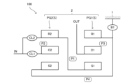
- FIG. 1 is a skeleton diagram of a unit according to an embodiment of the present invention.
- FIG. 2 is an engagement table showing the engagement state of each engagement element at each gear stage.
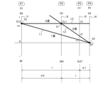
- FIG. 3 is a speed diagram of the unit.
- FIG. 4 is a skeleton diagram of a modified example.
- FIG. 5A is a skeleton diagram of another modification.
- FIG. 5B is a skeleton diagram of yet another modification.
- FIG. 6A is a skeleton diagram of yet another modification.
- FIG. 6B is a velocity diagram of the modified example shown in FIG. 6A.
- FIG. 7A is a skeleton diagram of yet another modification.
- FIG. 7B is a velocity diagram of the modification shown in FIG. 7A.
- Unit means any device that has a power transmission mechanism inside, such as a gear mechanism or differential gear mechanism, and includes a motor unit that has a motor and a power transmission mechanism, an automatic transmission unit, a reduction gear unit, etc. .
- Transmission ratio is the value obtained by dividing the input rotational speed of the unit by the output rotational speed.
- “Input rotation” includes not only rotation input to the unit from a power source outside the unit, but also rotation input to the unit from a power source within the unit.
- the "interstage ratio” is the value obtained by dividing the larger (low-speed) gear ratio by the smaller (high-speed) gear ratio of the two gear ratios realized by the unit.
- Axial direction means the axial direction of the rotating shaft of the parts that make up the unit.
- the parts include motors, gear mechanisms, differential gear mechanisms, etc.
- Ring direction means the radial direction from the central axis of the rotating shaft.
- Housing means a container that houses the motor, inverter, and power transmission mechanism, and is composed of one or more cases.
- a mode in which the case housing the motor, the case housing the inverter, and the case housing the power transmission mechanism are integrally formed is called “3in1.”
- Motor means a rotating electrical machine that has a motor function, and may have a generator function in addition to the motor function.
- Element A is connected to element B means that element A is connected to element B, either upstream or downstream, in a manner that allows power transmission between element A and element B.
- the power input side is upstream, and the power output side is downstream.
- Element A is not limited to being connected to element B directly or via another member, and may be connected via a clutch, etc.
- Element A is fixed to element B refers to both the manner in which element A is directly fixed to element B, and the manner in which element A is fixed to element B via element C other than element A and B. included. “Element A is fixed” means that element A is fixed to another element and cannot rotate.
- Element A and element B overlap when viewed in a specified direction refers to a state in which element A and element B are lined up in a specified direction (axial direction, radial direction, gravity direction, etc.) and at least partially overlap when observed from the specified direction. This is synonymous with "element A and element B overlap in a specified direction.”
- element A and element B overlap when viewed in the axial direction element A and element B are coaxial.
- element A and element B are drawn lined up in a specified direction in a drawing, this means that element A and element B overlap when viewed in the specified direction.
- element A and element B do not overlap when viewed in a predetermined direction means that element A and element B are not lined up in a predetermined direction (axial direction, radial direction, gravity direction, vehicle running direction, etc.). , refers to a state in which element A and element B do not have any overlapping portion when observed from a predetermined direction. This is synonymous with "element A and element B do not overlap in a predetermined direction". In the drawing, when element A and element B are drawn so as not to be lined up in a predetermined direction, it means that element A and element B do not overlap when viewed in the predetermined direction.
- Element A is arranged between elements B and C when viewed from a predetermined direction
- element A is located between elements B and C when observed from a predetermined direction (axial direction, radial direction, gravity direction, etc.). It means that something in between is observed.
- element B, element A, and element C are arranged in this order along the axial direction, element A is observed to be between element B and element C when viewed in the radial direction, so element A can be said to be located between element B and element C.
- Element A does not need to overlap elements B and C when viewed in the axial direction.
- element A is drawn between elements B and C in the drawing, it means that element A is located between elements B and C when viewed in a predetermined direction.
- Element A is positioned axially outward of element B means that element A is positioned on one axial side or the other axial side of element B, and includes cases where element A and element B overlap when viewed in the axial direction, as well as cases where element A and element B are in different radial positions and therefore do not overlap.
- “Arranged close to each other” means that two elements have a portion that overlaps with each other in an axial or radial view, and no other element is sandwiched between the two elements. .
- "two engaging elements are arranged close to each other” means that a planetary gear mechanism or the like is not arranged between the two engaging elements. If no other element is drawn between element A and element B in the drawing, it means that element A and element B are arranged close to each other.
- One side of the engagement element and “the other side of the engagement element” refer to an engagement element that is relatively non-rotatable when the engagement element is in the engaged state and becomes relatively rotatable when the engagement element is in the released state. means two elements contained in.
- “One side of the engagement element” and “the other side of the engagement element” may be a combination of rotating elements or a combination of a rotating element and a non-rotating element, and generally the former is called a clutch, and the latter is called a brake.
- one side of the engagement element means either “one side of the engagement element” or “the other side of the engagement element”.
- FIG. 1 is a skeleton diagram showing the basic structure of a unit 100 according to an embodiment of the present invention.
- the unit 100 is a forward drive unit for an electric vehicle that changes the rotation input from a motor as a power source (not shown) to an input element IN at a gear ratio corresponding to a gear position, and transmits it from an output element OUT to a drive wheel (not shown). It is a 3-speed automatic transmission unit.
- the input element IN and the output element OUT each include a gear, a rotating shaft, and the like. Since the motor can be switched between forward rotation and reverse rotation, the unit 100 is clearly different in design concept from a vehicle unit that uses an internal combustion engine as a power source in that it does not have a reverse gear.
- the unit 100 is a so-called 3-in-1 unit that houses an input element IN, a gear device 2, first to third engagement elements CL1, CL2, B1, an output element OUT, and a motor and an inverter (not shown) in a housing 1. .
- the housing 1 is non-rotatably fixed to the vehicle.
- the motor is electrically connected to a battery (not shown) outside the unit 100 via an inverter, and receives power from the battery to function as an electric motor.
- the motor can also function as a generator.
- the gear device 2 is constructed by arranging a first planetary gear mechanism PG1 and a second planetary gear mechanism PG2 close to each other and coupling their rotating elements at two locations.
- the first planetary gear mechanism PG1 includes a first sun gear S1 as a first rotating element, a plurality of first pinion gears (not shown), and a second rotating element that rotatably supports the plurality of first pinion gears.
- This is a single pinion planetary gear mechanism having a first carrier C1 and a first ring gear R1 as a third rotating element.
- the first sun gear S1 meshes with a plurality of first pinion gears, and the plurality of first pinion gears mesh with a first ring gear R1.
- the second planetary gear mechanism PG2 includes a second sun gear S2 as a fourth rotating element, a plurality of second pinion gears (not shown), and a fifth rotating element that rotatably supports the plurality of second pinion gears.
- This is a single pinion planetary gear mechanism having two carriers C2 and a second ring gear R2 as a sixth rotating element.
- the second sun gear S2 meshes with a plurality of second pinion gears, and the plurality of second pinion gears mesh with a second ring gear R2.
- the S in parentheses next to the symbols PG1 and PG2 in the figure indicates that the planetary gear mechanism is a single pinion planetary gear mechanism. Although it does not appear in this embodiment, if the planetary gear mechanism is a double pinion planetary gear mechanism, a letter D in parentheses will be added next to PG1 and PG2.
- the first sun gear S1 is coupled to the second ring gear R2.
- the first ring gear R1 is coupled to the second sun gear S2.
- the first rotational part P1 is composed of the first sun gear S1 and the second ring gear R2
- the second rotational part P2 is composed of a second carrier C2
- a third rotational part P3 is composed of a first carrier C1
- a fourth rotational part P4 is composed of a first ring gear R1 and a second sun gear S2.
- the rotation speed of the output element OUT is the output rotation speed of the unit 100.
- the first engagement element CL1 is a hydraulic or electric clutch. If the two parts of the first engaging element CL1 that are to be engaged when the first engaging element CL1 is brought into the engaged state are one side and the other side, one side is connected to the input element IN. The other side is connected to a second rotating part P2 made up of a second carrier C2. Thereby, by engaging the first engagement element CL1, the input element IN can be connected to the second rotating portion P2 constituted by the second carrier C2.
- the second engagement element CL2 is a hydraulic or electric clutch. If the two parts of the second engaging element CL2 that are to be engaged when the second engaging element CL2 is brought into the engaged state are one side and the other side, one side is connected to the input element IN. The other side is connected to a first rotational portion P1 that includes a first sun gear S1 and a second ring gear R2. Thereby, by engaging the second engagement element CL2, the input element IN can be connected to the first rotation portion P1 constituted by the first sun gear S1 and the second ring gear R2.
- first engagement element CL1 and one side of the second engagement element CL2 are both connected to the input element IN and rotate integrally, so they can be shared, that is, configured as an integral part.
- first engagement element CL1 and the second engagement element CL2 is constituted by a multi-disc clutch in which a plurality of friction plates are arranged between a drum and a hub, the outer periphery of one drum is connected to the other.
- the hub By forming the hub, it is possible to construct it as an integral part. Thereby, the number of parts of the unit 100 can be reduced.
- the third engagement element B1 is a hydraulic or electric brake. If the two parts of the third engagement element B1 that are engaged when the third engagement element B1 is in an engaged state are called one side and the other side, one side is connected to the fourth rotation part P4 consisting of the first ring gear R1 and the second sun gear S2, and the other side is fixed to the housing 1. As a result, when the third engagement element B1 is engaged, the fourth rotation part P4 consisting of the first ring gear R1 and the second sun gear S2 can be fixed to the housing 1.
- actuators for the second engagement element CL2 and the third engagement element B1 in addition to actuators that are less subject to layout constraints (such as hydraulic actuators that supply hydraulic pressure from a control valve unit), actuators that are more subject to layout constraints (such as electric actuators that need to be fixed to the housing 1 or the like and connected to a power cable due to reaction forces, or hydraulic actuators that need to have a hydraulic supply unit attached to the housing 1 or the like and connected to the hydraulic supply unit via piping) can be used.
- actuators that are less subject to layout constraints such as hydraulic actuators that supply hydraulic pressure from a control valve unit
- actuators that are more subject to layout constraints such as electric actuators that need to be fixed to the housing 1 or the like and connected to a power cable due to reaction forces, or hydraulic actuators that need to have a hydraulic supply unit attached to the housing 1 or the like and connected to the hydraulic supply unit via piping
- the third engagement element B1 may be configured with a selectable one-way clutch.
- a selectable one-way clutch is composed of a pair of ratchet mechanisms whose operating states can be switched by an electric actuator and which limit rotation in different directions.When only one of the pair of ratchet mechanisms is operated, it becomes a one-way clutch state, and the This clutch becomes engaged when both of its ratchet mechanisms are operated.
- the input element IN can be selectively connected to the first rotational part P1 consisting of the first sun gear S1 and the second ring gear R2, or the second rotational part P2 consisting of the second carrier C2, by engaging one of the first engagement element CL1 and the second engagement element CL2 and disengaging the other.
- the input element IN can be connected to the first rotational part P1 and the second rotational part P2.
- the fourth rotating portion P4 consisting of the first ring gear R1 and the second sun gear S2 can be switched to a rotating state or a non-rotating state.
- the first to third engaging elements CL1, CL2, B1 are positioned axially outward of the gear device 2. Because no engaging elements are positioned between the first planetary gear mechanism PG1 and the second planetary gear mechanism PG2, the layout freedom of the first to third engaging elements CL1, CL2, B1 is increased, and the axial dimension of the unit 100 can be reduced.
- first to third engagement elements CL1, CL2, and B1 can overlap with the gear device 2 when viewed in the axial direction. When these are made to overlap, the radial dimension of the unit 100 can be reduced.
- FIG. 2 is an engagement table showing the relationship between the engagement states of the first to third engagement elements CL1, CL2, and B1 and the gear stages realized in the unit 100.
- black circles indicate engaged states
- blank circles indicate released states.
- the first speed is achieved by engaging the second engagement element CL2 and the third engagement element B1 and releasing the first engagement element CL1.
- the second speed is achieved by engaging the first engagement element CL1 and the third engagement element B1 and releasing the second engagement element CL2.
- the third speed is achieved by engaging the first engagement element CL1 and the second engagement element CL2 and releasing the third engagement element B1.
- Each gear stage is realized by engaging two of the first to third engagement elements CL1, CL2, and B1, and only one engagement element is released. Even if the engagement element to be released is in the released state, such as in a multi-disc clutch, the parts that cause relative rotation will come into contact with each other and generate drag torque. The smaller the number, the more mechanical loss can be reduced. In this embodiment, only one engagement element is released in any gear stage, so engagement elements that generate drag torque are used as the first to third engagement elements CL1, CL2, and B1. Also, mechanical loss can be suppressed and the electricity consumption of the vehicle in which the unit 100 is mounted can be improved.
- FIG. 3 is a speed diagram of the unit 100.
- the first to fourth rotational parts P1 to P4 are arranged in this order, and the vertical lines l1 to l4 correspond to each rotational part.
- first planetary gear mechanism PG1 is a single pinion planetary gear mechanism
- first carrier C1 is disposed between the first sun gear S1 and the first ring gear R1.
- second planetary gear mechanism PG2 is also a single pinion planetary gear mechanism
- the second carrier C2 is disposed between the second sun gear S2 and the second ring gear R2.
- the vertical line l3 corresponds to the output element OUT.
- the distance ⁇ 1 between the vertical lines l3 and l4 is the value obtained by dividing the number of teeth of the first sun gear S1 by the number of teeth of the first ring gear R1. Further, when the interval between vertical line l4 and vertical line l2 is 1, the interval ⁇ 2 between vertical line l2 and vertical line l1 is the value obtained by dividing the number of teeth of second sun gear S2 by the number of teeth of second ring gear R2. .
- Straight lines L1 to L3 corresponding to each gear stage are drawn on the speed diagram.
- the rotational speed of each rotating portion P1 to P4 at each gear stage is represented by the ordinate of the intersection of the straight line L1 to L3 corresponding to each gear stage and the vertical line l1 to l4.
- the second engagement element CL2 and the third engagement element B1 are engaged, and the first engagement element CL1 is released.
- the rotational speeds of the input element IN and the first rotational part P1 become equal, and the rotational speed of the fourth rotational part P4 becomes zero, so the straight line L1 corresponding to the first speed becomes a straight line passing through the points X3 and X2.
- the rotational speed of the output element OUT is r1, which is the ordinate of the intersection of the straight line L1 and the vertical line l3. Therefore, the gear ratio in the first speed is rin/r1, where rin is the rotational speed of the input element IN.
- the first engagement element CL1 and the third engagement element B1 are engaged, and the second engagement element CL2 is released.
- the rotational speeds of the input element IN and the second rotational portion P2 become equal, and the rotational speed of the fourth rotational portion P4 becomes zero, so the straight line L2 corresponding to the second speed is a straight line passing through the points X1 and X2.
- This is a straight line with a greater slope than L1.
- the rotation speed of the output element OUT is r2, which is the ordinate of the intersection of the straight line L2 and the vertical line l3. Therefore, the gear ratio in the second speed is rin/r2, where rin is the rotational speed of the input element IN. Since r2 is larger than r1, the gear ratio of the second gear is smaller than the gear ratio of the first gear.
- the first engagement element CL1 and the second engagement element CL2 are engaged, and the third engagement element B1 is released.
- the rotational speeds of the input element IN, the first to fourth rotation parts P1 to P4, and the output element OUT become equal, so the straight line L3 corresponding to the third speed becomes a straight line with zero slope passing through the points X3 and X1.
- the gear ratio in the third gear is 1, which is smaller than the gear ratio in the first and second gears.
- the unit 100 three gears can be realized, so the gear ratio is smaller than that of a unit with two forward speeds, and the shock during gear shifting can be suppressed to be smaller than that of a unit with two forward speeds. Can be done. Further, since the first to third speeds can be used for low speed, medium speed, and high speed, respectively, it is possible to set an appropriate gear ratio depending on the speed range.
- the gear ratio is 1 in third gear.
- all rotating parts P1 to P4 that make up the gear device 2 rotate at the same rotational speed, which reduces power transmission loss caused by differential rotation between the rotating parts.
- Third gear is used frequently for high-speed cruising, so achieving a gear ratio of 1 in third gear provides a significant improvement in electricity consumption.
- FIG. 4 is a skeleton diagram of a unit 100 according to a modification.
- the skeleton diagram shown in FIG. 1 shows that one side of the first engaging element CL1 is connected to the input element IN via the first connecting member M1 passing through the inner peripheral side of the gear device 2, and the other side of the first engagement element CL1 is connected to the input element IN through the first connecting member M1 passing through the inner peripheral side of the gear device 2.
- the difference is that it is connected to a second rotating portion P2 made of a second carrier C2 via a second connecting member M2 that passes through the inner circumferential side.
- the first engagement element CL1 and the second engagement element CL2 are distributed and arranged on both sides of the gear device 2 in the axial direction, It is possible to adopt a layout in which the engagement element CL2 is not arranged on the inner peripheral side. This makes it easier to adopt actuators that are susceptible to layout constraints as the actuators for the first to third engagement elements CL1, CL2, and B1, and provides freedom of selection of actuators used for the first to third engagement elements CL1, CL2, and B1. degree will improve.
- FIG. 5A is a skeleton diagram of a unit 100 according to another modification.
- the first planetary gear mechanism PG1 and the second planetary gear mechanism PG2 are single pinion planetary gear mechanisms like the unit 100 shown in FIG. 1.
- the first rotation part P1 is configured by combining the first sun gear S1 and the second ring gear R2
- the second rotation part P2 is configured by the second carrier C2
- the third rotation part P3 is configured by combining the first sun gear S1 and the second ring gear R2
- the first carrier C1 constitutes the fourth rotating portion P4, which is constituted by combining the first ring gear R1 and the second sun gear S2.
- one side of the first engagement element CL1 is connected to the input element IN
- the other side of the first engagement element CL1 is connected to the second carrier C2 as the second rotation part P2
- the second engagement element CL2 One side of the second engagement element CL2 is connected to the input element IN
- the other side of the second engagement element CL2 is connected to the first sun gear S1 and the second ring gear R2 as the first rotation part P1
- one side of the third engagement element B1 is connected to the input element IN.
- the other side of the third engagement element B1 is fixed to the housing 1.
- the first to third engagement elements CL1, CL2, and B1 are respectively arranged on the outer side of the gear device 2 in the axial direction, so the first to third engagement elements CL1, CL2 , B1 is increased, and the axial dimension of the unit 100 can be reduced.
- first to third engagement elements CL1, CL2, and B1 can overlap with the gear device 2 when viewed in the axial direction. When these are made to overlap, the radial dimension of the unit 100 can be reduced.
- one side of the first engagement element CL1 and one side of the second engagement element CL2 can be shared (integrated), and thereby the number of parts of the unit 100 can be reduced.
- the engagement table is the same as that shown in Figure 2, and three gear stages can be achieved by changing two of the first to third engagement elements CL1, CL2, B1 that are engaged. Because the interstage ratio is small, an appropriate gear ratio can be set according to the speed range. Also, because the gear ratio is 1 in third gear, power transmission loss caused by differential rotation between rotating parts can be reduced.
- FIG. 5B is a skeleton diagram of a unit 100 according to yet another modification.
- the skeleton diagram shown in FIG. 5A shows that one side of the first engagement element CL1 is connected to the input element IN via the first connection member M1 passing through the inner peripheral side of the gear device 2, and the other side of the first engagement element CL1 is connected to the input element IN through the first connecting member M1 passing through the inner peripheral side of the gear device 2.
- the difference is that it is connected to a second rotating portion P2 made of a second carrier C2 via a second connecting member M2 that passes through the inner circumferential side.
- the first engagement element CL1 and the second engagement element CL2 are distributed and arranged on both sides of the gear device 2 in the axial direction, and the first engagement element CL1 is It is possible to adopt a layout in which the engagement element CL2 is not arranged on the inner peripheral side. This makes it easier to adopt actuators that are susceptible to layout constraints as the actuators for the first to third engagement elements CL1, CL2, and B1, and provides freedom of selection of actuators used for the first to third engagement elements CL1, CL2, and B1. degree will improve.
- FIG. 6A is a skeleton diagram of unit 100 according to yet another modified example.
- first planetary gear mechanism PG1 is a double-pinion planetary gear mechanism.
- first carrier C1 rotatably supports a number of inner pinion gears (not shown) that mesh with first sun gear S1 and a number of outer pinion gears (not shown) that mesh with first ring gear R1, and further, the number of inner pinion gears mesh with the number of outer pinion gears.
- Second planetary gear mechanism PG2 is a single-pinion planetary gear mechanism like unit 100 shown in FIG. 1.
- the first rotational part P1 is composed of the first sun gear S1 and the second ring gear R2
- the second rotational part P2 is composed of the second carrier C2
- the third rotational part P3 is composed of the first ring gear
- the fourth rotating portion P4 is formed by combining the first carrier C1 and the second sun gear S2.
- one side of the first engagement element CL1 is connected to the input element IN
- the other side of the first engagement element CL1 is connected to the second carrier C2 as the second rotation part P2
- the second engagement element CL2 One side of the second engagement element CL2 is connected to the input element IN
- the other side of the second engagement element CL2 is connected to the first sun gear S1 and the second ring gear R2 as the first rotation part P1
- one side of the third engagement element B1 is connected to the input element IN.
- the other side of the third engagement element B1 is fixed to the housing 1.
- the first to third engagement elements CL1, CL2, and B1 are respectively arranged on the outer side of the gear device 2 in the axial direction, so the first to third engagement elements CL1, CL2 , B1 is increased, and the axial dimension of the unit 100 can be reduced.
- first to third engagement elements CL1, CL2, and B1 can overlap with the gear device 2 when viewed in the axial direction. When these are made to overlap, the radial dimension of the unit 100 can be reduced.
- one side of the first engagement element CL1 and one side of the second engagement element CL2 can be shared (integrated), and thereby the number of parts of the unit 100 can be reduced.
- the engagement table is the same as that shown in FIG. 2, and three gears can be realized by changing the two that engage among the first to third engagement elements CL1, CL2, and B1. . Since the inter-stage ratio becomes smaller, an appropriate gear ratio can be set depending on the speed range. Furthermore, since the gear ratio is 1 in the third speed, it is possible to reduce power transmission loss due to differential rotation between rotating parts.
- FIG. 6B is a speed diagram of the modified example shown in FIG. 6A. Because the first planetary gear mechanism PG1 is a double-pinion planetary gear mechanism, the first ring gear R1 is disposed between the first sun gear S1 and the first carrier C1 on the speed diagram. In other words, the second and third rotating elements are reversed from the case of a single-pinion planetary gear mechanism.
- FIG. 7A is a skeleton diagram of a unit 100 according to yet another modification.
- the second planetary gear mechanism PG2 is a double pinion planetary gear mechanism. That is, the second carrier C2 rotatably supports a plurality of inner pinion gears (not shown) that mesh with the second sun gear S2 and a plurality of outer pinion gears (not shown) that mesh with the second ring gear R2, Further, the plurality of inner pinion gears and the plurality of outer pinion gears are in mesh with each other.
- the first planetary gear mechanism PG1 is a single pinion planetary gear mechanism like the unit 100 shown in FIG.
- the first rotating portion P1 is configured by combining the first sun gear S1 and the second carrier C2
- the second rotating portion P2 is configured by the second ring gear R2
- the third rotating portion P3 is configured by combining the first sun gear S1 and the second carrier C2.
- the first carrier C1 constitutes the fourth rotating portion P4, which is constituted by combining the first ring gear R1 and the second sun gear S2.
- first engagement element CL1 is connected to the input element IN
- the other side of the first engagement element CL1 is connected to the second ring gear R2 as the second rotation part P2
- second engagement element CL2 One side of the second engagement element CL2 is connected to the input element IN
- the other side of the second engagement element CL2 is connected to the first sun gear S1 as the first rotation part P1 and the second carrier C2
- one side of the third engagement element B1 is connected to the input element IN.
- the other side of the third engagement element B1 is fixed to the housing 1.
- the first to third engagement elements CL1, CL2, and B1 are respectively disposed on the outside in the axial direction of the gear device 2, so the first to third engagement elements CL1, CL2 , B1 is increased, and the axial dimension of the unit 100 can be reduced.
- first to third engagement elements CL1, CL2, and B1 can overlap with the gear device 2 when viewed in the axial direction. When these are made to overlap, the radial dimension of the unit 100 can be reduced.
- one side of the first engagement element CL1 and one side of the second engagement element CL2 can be shared (integrated parts), thereby reducing the number of parts of the unit 100.
- the engagement table is the same as that shown in FIG. 2, and three gears can be realized by changing the two that engage among the first to third engagement elements CL1, CL2, and B1. . Since the inter-stage ratio becomes smaller, an appropriate gear ratio can be set depending on the speed range. Furthermore, since the gear ratio is 1 in the third speed, it is possible to reduce power transmission loss due to differential rotation between rotating parts.
- FIG. 7B is a speed diagram of the modified example shown in FIG. 7A. Because the second planetary gear mechanism PG2 is a double-pinion planetary gear mechanism, the second ring gear R2 is disposed between the second sun gear S2 and the second carrier C2 on the speed diagram. In other words, the fifth and sixth rotating elements are reversed from the case of a single-pinion planetary gear mechanism.
- the unit 100 includes an input element IN; Output element OUT and A gear device 2 (FIG. 3) in which a first rotational portion P1, a second rotational portion P2, a third rotational portion P3, and a fourth rotational portion P4 are arranged in this order on a speed diagram; Equipped with The input element IN is connectable to the first rotation part P1 and connectable to the second rotation part P2, The output element OUT is connected to the third rotation part P3, The fourth rotating portion P4 can be switched between a rotating state and a non-rotating state.
- the gear device 2 is A single-pinion first planetary gear mechanism that includes a first sun gear S1, a first carrier C1, and a first ring gear R1, and in which the first carrier C1 is arranged between the first sun gear S1 and the first ring gear R1 on a speed diagram.
- PG1 Figure 3
- a single pinion second planetary gear mechanism that includes a second sun gear S2, a second carrier C2, and a second ring gear R2, and the second carrier C2 is arranged between the second sun gear S2 and the second ring gear R2 on the speed diagram.
- the first rotation portion P1 is configured by coupling a first sun gear S1 and a second ring gear R2,
- the second rotation part P2 is composed of a second carrier C2,
- the third rotation part P3 is composed of the first carrier C1,
- the fourth rotation portion P4 is configured by coupling the first ring gear R1 and the second sun gear S2.
- the unit 100 includes an input element IN; Output element OUT and A gear device 2 (FIG. 6B) in which a first rotational portion P1, a second rotational portion P2, a third rotational portion P3, and a fourth rotational portion P4 are arranged in this order on a speed diagram; Equipped with.
- the input element IN is connectable to the first rotation part P1 and connectable to the second rotation part P2,
- the output element OUT is connected to the third rotation part P3,
- the fourth rotating portion P4 can be switched between a rotating state and a non-rotating state.
- the gear device 2 is A double pinion first planetary gear mechanism that includes a first sun gear S1, a first ring gear R1, and a first carrier C1, and in which the first ring gear R1 is arranged between the first sun gear S1 and the first carrier C1 on a speed diagram.
- PG1 Figure 6B
- a single-pinion second planetary gear mechanism that includes a second sun gear S2, a second carrier C2, and a second ring gear R2, and in which the second carrier C2 is arranged between the second sun gear S2 and the second ring gear R2 on the speed diagram.
- PG2 ( Figure 6B) and Equipped with.
- the first rotation portion P1 is configured by combining a first sun gear S1 and a second ring gear R2,
- the second rotation part P2 is composed of a second carrier C2
- the third rotation part P3 is composed of a first ring gear R1
- the fourth rotation portion P4 is configured by coupling the first carrier C1 and the second sun gear S2.
- the unit 100 includes an input element IN; Output element OUT and A gear device 2 (FIG. 7B) in which a first rotational portion P1, a second rotational portion P2, a third rotational portion P3, and a fourth rotational portion P4 are arranged in this order on a speed diagram; Equipped with The input element IN is connectable to the first rotation part P1 and connectable to the second rotation part P2, The output element OUT is connected to the third rotation part P3, The fourth rotating portion P4 can be switched between a rotating state and a non-rotating state.
- the gear device 2 is A single-pinion first planetary gear mechanism that includes a first sun gear S1, a first carrier C1, and a first ring gear R1, and in which the first carrier C1 is arranged between the first sun gear S1 and the first ring gear R1 on a speed diagram.
- PG1 Figure 7B
- a double pinion second planetary gear mechanism that includes a second sun gear S2, a second ring gear R2, and a second carrier C2, and the second ring gear R2 is arranged between the second sun gear S2 and the second carrier C2 on the speed diagram.
- the first rotation portion P1 is configured by combining a first sun gear S1 and a second carrier C2
- the second rotation part P2 is composed of a second ring gear R2
- the third rotation part P3 is composed of the first carrier C1
- the fourth rotation portion P4 is configured by coupling the first ring gear R1 and the second sun gear S2.
- three gear stages can be achieved by switching the connection destination of the input element IN (either or both of the first rotating part P1 and the second rotating part P2) and the rotation state of the fourth rotating part P4. Since the interstage ratio is small, an appropriate gear ratio can be set according to the speed range, and since the gear ratio is 1 at third gear, power transmission loss caused by differential rotation between rotating parts can be reduced.
- the unit 100 includes a first engagement element CL1; a second engagement element CL2; a third engagement element B1; Equipped with One side of the first engagement element CL1 is connected to the input element IN, The other side of the first engagement element CL1 is connected to the second rotation portion P2, One side of the second engagement element CL2 is connected to the input element IN, The other side of the second engagement element CL2 is connected to the first rotation portion P1, One side of the third engagement element B1 is connected to the fourth rotation portion P4, The other side of the third engagement element B1 is fixed.
- the first to third engagement elements CL1, CL2, and B1 can overlap with the gear device 2 when viewed in the axial direction.
- the radial dimension of the unit 100 can be reduced.
- the first to third engagement elements CL1, CL2, and B1 are respectively arranged on the outside in the axial direction of the gear device 2. be done. This increases the degree of freedom in the layout of the first to third engaging elements CL1, CL2, and B1, and also allows the axial dimension of the unit 100 to be reduced.
- one side of the first engagement element CL1 is connected to the input element IN via the first connection member M1 passing through the inner peripheral side of the gear device 2, and The other side of the engagement element CL1 is connected to the second rotating portion P2 via a second connecting member M2 passing through the inner peripheral side of the gear device 2.
- the first engagement element CL1 and the second engagement element CL2 are arranged to be distributed on both sides in the axial direction with respect to the gear device 2, and the first engagement element CL1 is not arranged on the inner peripheral side of the second engagement element CL2. layout can be adopted. This makes it easier to employ actuators that are susceptible to layout constraints as the actuators for the first to third engagement elements CL1, CL2, and B1, and the degree of freedom in selecting actuators is improved.
- one side of the first engagement element CL1 and one side of the second engagement element CL2 are constructed as an integral part. It's okay. Thereby, the number of parts of the unit 100 can be reduced.
- FIGS. 1, 4, 5A, 5B, 6A, and 7A are part of the application examples of the present invention, and the skeleton diagrams of units to which the present invention is applied are not limited to these.
- first planetary gear mechanism PG1 and the second planetary gear mechanism PG2 may be used as the first planetary gear mechanism PG1 and the second planetary gear mechanism PG2.
- Housing 2 Gear device 100: Unit CL1: First engagement element CL2: Second engagement element B1: Third engagement element S1: First sun gear S2: Second sun gear C1: First carrier C2: Second Carrier R1: First ring gear R2: Second ring gear M1: First connecting member M2: Second connecting member P1: First rotating part P2: Second rotating part P3: Third rotating part P4: Fourth rotating part IN: Input Element OUT: Output element PG1: First planetary gear mechanism PG2: Second planetary gear mechanism
Landscapes
- Engineering & Computer Science (AREA)
- General Engineering & Computer Science (AREA)
- Mechanical Engineering (AREA)
- Structure Of Transmissions (AREA)
Priority Applications (3)
| Application Number | Priority Date | Filing Date | Title |
|---|---|---|---|
| EP23867853.6A EP4592558A4 (en) | 2022-09-22 | 2023-07-05 | UNIT |
| JP2024548091A JP7713112B2 (ja) | 2022-09-22 | 2023-07-05 | ユニット |
| CN202380061689.6A CN119923532A (zh) | 2022-09-22 | 2023-07-05 | 组件 |
Applications Claiming Priority (2)
| Application Number | Priority Date | Filing Date | Title |
|---|---|---|---|
| JP2022150954 | 2022-09-22 | ||
| JP2022-150954 | 2022-09-22 |
Publications (1)
| Publication Number | Publication Date |
|---|---|
| WO2024062726A1 true WO2024062726A1 (ja) | 2024-03-28 |
Family
ID=90454412
Family Applications (1)
| Application Number | Title | Priority Date | Filing Date |
|---|---|---|---|
| PCT/JP2023/024952 Ceased WO2024062726A1 (ja) | 2022-09-22 | 2023-07-05 | ユニット |
Country Status (4)
| Country | Link |
|---|---|
| EP (1) | EP4592558A4 (https=) |
| JP (1) | JP7713112B2 (https=) |
| CN (1) | CN119923532A (https=) |
| WO (1) | WO2024062726A1 (https=) |
Citations (5)
| Publication number | Priority date | Publication date | Assignee | Title |
|---|---|---|---|---|
| CN106195194A (zh) | 2016-08-31 | 2016-12-07 | 吉林大学 | 一种基于两挡变速器的电驱动桥系统及其控制方法 |
| CN206000959U (zh) | 2016-08-31 | 2017-03-08 | 吉林大学 | 一种基于两挡变速器的电驱动桥系统 |
| DE102019116360A1 (de) | 2019-06-17 | 2020-12-17 | Schaeffler Technologies AG & Co. KG | Planetengetriebe für ein Kraftfahrzeug |
| DE102019119951A1 (de) | 2019-07-24 | 2021-01-28 | Schaeffler Technologies AG & Co. KG | Antriebsvorrichtung für ein Kraftfahrzeug mit drehfest verbundenen Planetenradträgern |
| KR20210154549A (ko) * | 2020-06-12 | 2021-12-21 | 현대자동차주식회사 | 하이브리드 차량의 파워트레인 |
Family Cites Families (4)
| Publication number | Priority date | Publication date | Assignee | Title |
|---|---|---|---|---|
| US20150158382A1 (en) * | 2013-12-05 | 2015-06-11 | Avl Powertrain Engineering, Inc. | Two-speed transmission for electric vehicle |
| DE102013226474A1 (de) * | 2013-12-18 | 2015-06-18 | Zf Friedrichshafen Ag | Getriebe |
| DE102013226479B4 (de) * | 2013-12-18 | 2022-08-18 | Zf Friedrichshafen Ag | Getriebe |
| DE102018001508B3 (de) * | 2018-02-26 | 2019-05-29 | Daimler Ag | Elektrische Antriebsvorrichtung für ein Kraftfahrzeug, insbesondere für einen Kraftwagen |
-
2023
- 2023-07-05 CN CN202380061689.6A patent/CN119923532A/zh active Pending
- 2023-07-05 EP EP23867853.6A patent/EP4592558A4/en active Pending
- 2023-07-05 JP JP2024548091A patent/JP7713112B2/ja active Active
- 2023-07-05 WO PCT/JP2023/024952 patent/WO2024062726A1/ja not_active Ceased
Patent Citations (5)
| Publication number | Priority date | Publication date | Assignee | Title |
|---|---|---|---|---|
| CN106195194A (zh) | 2016-08-31 | 2016-12-07 | 吉林大学 | 一种基于两挡变速器的电驱动桥系统及其控制方法 |
| CN206000959U (zh) | 2016-08-31 | 2017-03-08 | 吉林大学 | 一种基于两挡变速器的电驱动桥系统 |
| DE102019116360A1 (de) | 2019-06-17 | 2020-12-17 | Schaeffler Technologies AG & Co. KG | Planetengetriebe für ein Kraftfahrzeug |
| DE102019119951A1 (de) | 2019-07-24 | 2021-01-28 | Schaeffler Technologies AG & Co. KG | Antriebsvorrichtung für ein Kraftfahrzeug mit drehfest verbundenen Planetenradträgern |
| KR20210154549A (ko) * | 2020-06-12 | 2021-12-21 | 현대자동차주식회사 | 하이브리드 차량의 파워트레인 |
Non-Patent Citations (1)
| Title |
|---|
| See also references of EP4592558A4 |
Also Published As
| Publication number | Publication date |
|---|---|
| EP4592558A4 (en) | 2026-02-25 |
| JP7713112B2 (ja) | 2025-07-24 |
| EP4592558A1 (en) | 2025-07-30 |
| CN119923532A (zh) | 2025-05-02 |
| JPWO2024062726A1 (https=) | 2024-03-28 |
Similar Documents
| Publication | Publication Date | Title |
|---|---|---|
| JP7719976B2 (ja) | ユニット | |
| JP7730431B2 (ja) | ユニット | |
| JP7741993B2 (ja) | ユニット | |
| JP7719975B2 (ja) | ユニット | |
| JP7713112B2 (ja) | ユニット | |
| JP7730430B2 (ja) | ユニット | |
| JP7769812B2 (ja) | ユニット | |
| JP7705566B2 (ja) | ユニット | |
| JP7705565B2 (ja) | ユニット | |
| WO2024062727A1 (ja) | ユニット | |
| WO2024062724A1 (ja) | ユニット | |
| WO2024062730A1 (ja) | ユニット | |
| WO2024062725A1 (ja) | ユニット | |
| JP7736937B2 (ja) | ユニット | |
| WO2024062708A1 (ja) | ユニット | |
| WO2024062709A1 (ja) | ユニット | |
| JP7713106B2 (ja) | ユニット | |
| JP7698801B2 (ja) | ユニット | |
| JP7698802B2 (ja) | ユニット | |
| WO2024014125A1 (ja) | ユニット | |
| WO2024014128A1 (ja) | ユニット | |
| WO2024014122A1 (ja) | ユニット | |
| WO2024014127A1 (ja) | ユニット | |
| WO2024014119A1 (ja) | ユニット | |
| WO2024014121A1 (ja) | ユニット |
Legal Events
| Date | Code | Title | Description |
|---|---|---|---|
| 121 | Ep: the epo has been informed by wipo that ep was designated in this application |
Ref document number: 23867853 Country of ref document: EP Kind code of ref document: A1 |
|
| DPE1 | Request for preliminary examination filed after expiration of 19th month from priority date (pct application filed from 20040101) | ||
| WWE | Wipo information: entry into national phase |
Ref document number: 2024548091 Country of ref document: JP |
|
| WWE | Wipo information: entry into national phase |
Ref document number: 202380061689.6 Country of ref document: CN |
|
| WWE | Wipo information: entry into national phase |
Ref document number: 2023867853 Country of ref document: EP |
|
| NENP | Non-entry into the national phase |
Ref country code: DE |
|
| ENP | Entry into the national phase |
Ref document number: 2023867853 Country of ref document: EP Effective date: 20250422 |
|
| WWP | Wipo information: published in national office |
Ref document number: 202380061689.6 Country of ref document: CN |
|
| WWP | Wipo information: published in national office |
Ref document number: 2023867853 Country of ref document: EP |