WO2024062540A1 - Image processing device - Google Patents
Image processing device Download PDFInfo
- Publication number
- WO2024062540A1 WO2024062540A1 PCT/JP2022/035027 JP2022035027W WO2024062540A1 WO 2024062540 A1 WO2024062540 A1 WO 2024062540A1 JP 2022035027 W JP2022035027 W JP 2022035027W WO 2024062540 A1 WO2024062540 A1 WO 2024062540A1
- Authority
- WO
- WIPO (PCT)
- Prior art keywords
- parallax
- reliability
- unit
- image
- image processing
- Prior art date
Links
- 238000012545 processing Methods 0.000 title claims abstract description 91
- 238000004364 calculation method Methods 0.000 claims abstract description 64
- 238000002372 labelling Methods 0.000 claims abstract description 22
- 238000012937 correction Methods 0.000 claims abstract description 18
- 238000000034 method Methods 0.000 claims description 16
- 238000003062 neural network model Methods 0.000 claims description 12
- 238000010586 diagram Methods 0.000 description 16
- 230000006870 function Effects 0.000 description 14
- 238000001514 detection method Methods 0.000 description 11
- 230000008569 process Effects 0.000 description 9
- 238000011156 evaluation Methods 0.000 description 7
- 238000010801 machine learning Methods 0.000 description 3
- 210000002569 neuron Anatomy 0.000 description 2
- 230000011218 segmentation Effects 0.000 description 2
- 241000283070 Equus zebra Species 0.000 description 1
- 230000004913 activation Effects 0.000 description 1
- 230000008859 change Effects 0.000 description 1
- 230000000694 effects Effects 0.000 description 1
- 230000006872 improvement Effects 0.000 description 1
- 238000012986 modification Methods 0.000 description 1
- 230000004048 modification Effects 0.000 description 1
- 230000003287 optical effect Effects 0.000 description 1
- 238000011160 research Methods 0.000 description 1
- 239000007787 solid Substances 0.000 description 1
- 230000007704 transition Effects 0.000 description 1
Images


Classifications
-
- G—PHYSICS
- G01—MEASURING; TESTING
- G01C—MEASURING DISTANCES, LEVELS OR BEARINGS; SURVEYING; NAVIGATION; GYROSCOPIC INSTRUMENTS; PHOTOGRAMMETRY OR VIDEOGRAMMETRY
- G01C3/00—Measuring distances in line of sight; Optical rangefinders
- G01C3/02—Details
- G01C3/06—Use of electric means to obtain final indication
Definitions
- the present invention relates to an image processing device.
- a stereo camera can measure the distance to an object by using the parallax of an overlapping region of images taken by two cameras arranged at a predetermined interval. Therefore, the stereo camera can accurately grasp the risk of collision with an object.
- Patent Document 1 discloses that an image capturing means for capturing an image of a target object and a stereo matching process are performed for each small region of a pair of images captured by the image capturing means to identify corresponding regions by determining mutual correlation.
- stereo processing means for acquiring an evaluation function that is a matching processing result, distance information to the target object obtained based on the evaluation function, and reliability information indicating the reliability thereof; setting a re-search range around the area, and based on the evaluation function calculated for the small area within the re-search range, correcting the evaluation function calculated for the target small area to obtain a modified evaluation function;
- a stereo image processing device characterized by comprising a parallax correction means for correcting distance information based on the obtained modified evaluation function.
- the device disclosed in Patent Document 1 corrects parallax by correcting the evaluation function determined for each matching block set in stereo matching. Therefore, in the device disclosed in Patent Document 1, depending on the situation of the captured image, even the corrected parallax may contain a large error, and there is room for improvement.
- the present invention has been made in view of the above, and an object of the present invention is to provide an image processing device that can accurately calculate parallax.
- an image processing device of the present invention includes a parallax calculation unit that calculates the parallax of images captured by a plurality of cameras, and a parallax calculation unit that classifies objects that appear in the images and types of the classified objects.
- a labeling unit that assigns a label to each pixel of the object according to the label
- a reliability calculation unit that calculates the reliability of the parallax for each label assigned
- a reliability calculation unit that calculates the parallax according to the calculated reliability.
- a parallax correction unit that corrects the parallax.
- FIG. 1 is a diagram showing the configuration of a stereo camera device including an image processing device according to the present embodiment.
- 5 is a flowchart showing the operation of the image processing device.
- 5 is a flowchart showing processing performed by a reliability calculation unit.
- FIG. 3 is a diagram illustrating an example of the configuration of data written to one pixel of a reliability image.
- 5 is a flowchart showing processing performed by an interpolation unit.
- FIG. 11 is a diagram for explaining step S34 shown in FIG. 10 .
- 5 is a flowchart showing processing performed by a recalculation unit.
- FIG. 1 is a diagram showing the configuration of a stereo camera device 1 including an image processing device 20 of this embodiment.
- FIG. 2 is a diagram showing the parallax image 130.
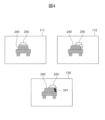
- FIG. 3 is a diagram showing the label image 140.
- FIG. 4 is a diagram illustrating the occlusion portion 241.
- FIG. 5 is a diagram showing the reliability table 51.
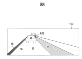
- FIG. 6 is a diagram showing the reliability image 150.
- the stereo camera device 1 is a type of sensor that is mounted on a vehicle and monitors the area around the vehicle.
- the stereo camera device 1 detects objects around the vehicle and measures the distance to the objects by utilizing the parallax of the overlapping areas of images 111, 112 captured by multiple cameras 11, 12 arranged at a predetermined interval in the horizontal direction.
- the stereo camera device 1 shown in FIG. 1 performs image processing using a left camera 11 and a right camera 12, a left image 111 taken by the left camera 11, and a right image 112 taken by the right camera 12.
- a device 20 is provided.
- the image processing device 20 is configured by, for example, a computer including a processor such as a CPU and a storage device such as a ROM and a RAM.
- the image processing device 20 realizes various functions of the image processing device 20 by the CPU executing programs stored in the ROM.
- the image processing device 20 includes a parallax calculation section 30, a labeling section 40, a reliability calculation section 50, a parallax correction section 60, and a recognition processing section 70.
- the parallax calculation unit 30 calculates the parallax of the left image 111 and the right image 112 captured by the left camera 11 and the right camera 12 for each pixel.
- the parallax calculation unit 30 of this embodiment has a neural network model.
- a left image 111 and a right image 112 are set in the input layer of the neural network model.
- the parallax between the left image 111 and the right image 112 is set in the output layer of the neural network model.
- weights, biases, and activation functions for each neuron are set.
- the neural network model is constructed by machine learning the weights and biases of each neuron using error backpropagation, etc., and is installed in the parallax calculation unit 30 in advance.
- the machine learning may be supervised learning.
- the parallax calculation unit 30 may have a model constructed by machine learning other than the neural network model.
- the model included in the parallax calculation unit 30 may be, for example, an optical flow model.
- the parallax calculation unit 30 generates a parallax image 130 in which the calculated parallax is stored in each pixel.
- the parallax image 130 is generated as an image in which the parallax corresponding to each pixel of the right image 112 is stored in each pixel of the right image 112, as shown in FIG. 2, for example. In the parallax image 130 shown in FIG. 2, the darker the color, the larger the parallax and the closer the distance.
- the labeling unit 40 classifies the subject appearing in the right image 112 and assigns a label according to the type of the classified subject to each pixel of the subject.
- the labeling unit 40 can classify objects and assign labels using a neural network model.
- the labeling unit 40 of this embodiment classifies objects and assigns labels using panoptic segmentation.
- a processing overview of panoptic segmentation is introduced in the paper by Kirillov et al., “Panoptic Feature Pyramid Networks,” 2019 IEEE/CVF Conference on CVPR.
- the labeling unit 40 can refer to the paper.
- the labeling unit 40 labels the objects in the right image 112 as road surfaces 210, puddles 220, gutters 230, vehicles 240, vehicles 250, and zebra zones 260, according to the learned label information. Classify by pixel. Then, the labeling unit 40 writes the label number of the label assigned to each subject for each pixel of the subject. In this way, the labeling unit 40 generates a label image 140 in which a label number is stored in each pixel.
- the labeling unit 40 performs the following processing in order to identify the occlusion portion 241. For example, as shown in FIG. 4, it is assumed that the right image 112 and the left image 111 have different degrees of overlap between the vehicles 240 and 250, and the occlusion portion 241 is not captured in the left image 111.
- the labeling unit 40 compares the parallaxes of the vehicle 240 and the vehicle 250, and identifies the area on the right side of the vehicle 240, which is the subject with a large parallax, as the occlusion portion 241.
- the width of the occlusion portion 241 is the number of pixels that is the difference between the parallax of the vehicle 240 and the parallax of the vehicle 250.
- the labeling unit 40 can also verify the consistency between the type of the classified subject and the label assigned to the subject based on the parallax calculated by the parallax calculation unit 30. For example, if the subject is a signboard with a picture of a person attached to it, the parallax of the pixels that make up the subject indicates a value that is approximately constant or changes linearly in the pixel group, and the subject is recognized as being flat. On the other hand, if the subject is an actual person, the parallax of the pixels that make up the subject indicates a value that changes nonlinearly in the pixel group, and the subject is recognized as being three-dimensional. For this reason, the labeling unit 40 can verify the consistency between the type of the classified subject and the label assigned to the subject by using the parallax image 130 in addition to the right image 112.
- the reliability calculation unit 50 calculates the reliability of parallax for each label given by the labeling unit 40.
- the reliability is an index that quantifies the magnitude of the error included in the parallax value. The smaller the error included in the parallax value, the higher the reliability. In this embodiment, the reliability is “low” if the error included in the parallax value is 20% or more, the reliability is “medium” if the error is 10% or more and less than 20%, and the reliability is “medium” if the error is less than 10%. is "high”.
- the reliability calculation unit 50 calculates the reliability in order to clarify the subject whose parallax is assumed to be inaccurate.
- the reliability calculation unit 50 calculates the reliability of the disparity using a reliability table 51 created in advance.
- the reliability table 51 is a table showing the correspondence between labels and reliability, as shown in FIG. 5.
- a reliability item of "0” indicates that the reliability is "invalid”
- a reliability item of "1” indicates that the reliability is "low”
- a reliability item of "2” indicates that the reliability is "medium”
- a reliability item of "3” indicates that the reliability is "high”.
- the reliability calculation unit 50 refers to the reliability table 51 and identifies the reliability corresponding to the label assigned by the labeling unit 40. The reliability calculation unit 50 then writes the identified reliability for each pixel of the subject to which the label is assigned. In this way, the reliability calculation unit 50 generates a reliability image 150 in which a label number and a reliability are stored for each pixel, as shown in FIG. 6.
- the parallax correction unit 60 corrects parallax according to the reliability calculated by the reliability calculation unit 50.
- the parallax correction unit 60 includes an interpolation unit 61 and a recalculation unit 62.
- the interpolation unit 61 interpolates the parallax whose reliability does not meet the standard based on the parallax calculated for the images 111 and 112 taken in the past.
- the interpolation unit 61 can correct the parallax image 130 by interpolating parallaxes whose reliability does not meet the standard.
- the interpolation unit 61 of the present embodiment determines whether or not to interpolate parallaxes whose reliability is "low” or "invalid” based on the parallaxes calculated for images 111 and 112 taken in the past, When it is determined that interpolation is to be performed, a parallax with a "high” reliability is used to interpolate a parallax with a "low” or "invalid" reliability.
- an area where the reliability calculated for the images 111 and 112 taken currently is “low” or “invalid” is calculated as "high” for the images 111 and 112 taken in the past.
- the interpolation unit 61 of the present embodiment determines to interpolate the parallax of which the reliability of the area is "low” or “invalid”, and uses the parallax of which the reliability is "high” adjacent to the area, Interpolates parallaxes whose reliability in the area is "low” or "invalid".
- the recalculation unit 62 recalculates the parallax whose reliability does not meet the standard using a method different from that of the parallax calculation unit 30.
- the recalculation unit 62 can correct the parallax image 130 by replacing the parallax whose reliability does not meet the standard with the recalculated parallax.
- the recalculation unit 62 of this embodiment recalculates the parallax whose reliability is "medium” or "low” by, for example, stereo matching.
- the recalculation unit 62 of this embodiment may use the parallax interpolated by the interpolation unit 61 as a target for recalculation. Note that when the parallax calculation unit 30 calculates the parallax by stereo matching, the recalculation unit 62 may recalculate the parallax using a neural network model.
- the recognition processing unit 70 detects objects around the vehicle based on the parallax corrected by the parallax correction unit 60, the reliability calculated by the reliability calculation unit 50, and the images 111 and 112. Specifically, the recognition processing unit 70 uses the corrected parallax image 130, reliability image 150, left image 111, and right image 112 to detect objects around the vehicle.
- a road surface area with "high” reliability has accurate parallax, and even small objects on the road surface can be detected.
- the recognition processing unit 70 changes the size of the object to be detected or the distance to the object according to the reliability. For example, in an area where the reliability is "low”, the recognition processing unit 70 detects, among objects on the road, objects whose height is greater than the error included in the parallax of the road.
- the recognition processing unit 70 detects a subject whose height is larger than the error included in the parallax of the road surface in the road surface area where the reliability is "low", and detects the object whose height is larger than the error included in the road surface parallax in the road surface area where the reliability is "high". , subjects whose height is smaller than the road surface area with "high” reliability are also detected. In this way, the recognition processing unit 70 can change the size of the object to be detected or the distance to the object depending on the reliability. As for the method of object detection itself, the recognition processing unit 70 can employ a known method.
- the parallax image 130 and the reliability image 150 are input to the recognition processing unit 70 in a manner that corresponds to each other pixel by pixel. That is, parallax, reliability, and label information are input to the recognition processing unit 70 in association with each other for each pixel.
- the recognition processing unit 70 can, for example, re-label a pixel whose reliability does not meet the standard after the fact or recalculate the reliability after the fact. That is, the recognition processing unit 70 can reconsider the data (reliability or label) acquired at the stage before object detection, and can improve the accuracy of object detection.
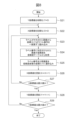
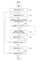
- FIG. 7 is a flowchart showing the operation of the image processing device 20.
- step S11 the parallax calculation unit 30 of the image processing device 20 generates a parallax image 130 from the left image 111 and the right image 112.
- step S12 the labeling unit 40 of the image processing device 20 classifies the subject using the right image 112 and the parallax image 130, and generates a label image 140 by assigning a label to each pixel of the subject.
- step S13 the reliability calculation unit 50 of the image processing device 20 calculates the reliability of parallax for each label using the reliability table 51, and generates the reliability image 150.
- step S14 the parallax correction unit 60 of the image processing device 20 corrects parallaxes whose reliability does not meet the standard.
- step S15 the recognition processing unit 70 of the image processing device 20 performs object detection using the parallax image 130, the reliability image 150, the right image 112, and the left image 111. Thereafter, the image processing device 20 performs a process according to the object detection result, such as transmitting a signal to the vehicle control device to issue an alarm or activate an automatic emergency brake, and ends this process.
- FIG. 8 is a flowchart showing the processing performed by the reliability calculation unit 50.
- FIG. 9 is a diagram showing an example of the structure of data written to one pixel of the reliability image 150.
- the X coordinate value indicates the horizontal coordinate value of the label image 140 and the reliability image 150.
- step S23 the reliability calculation unit 50 reads the label number of the coordinates (X, Y) from the label image 140 one pixel at a time.
- step S24 the reliability calculation unit 50 obtains the reliability of the parallax associated with the label number from the reliability table 51.
- step S25 the reliability calculation unit 50 writes the label number and reliability at the coordinates (X, Y) of the reliability image 150.
- the data written at this time is structured as shown in FIG. 9, for example.
- one pixel of data to be written has 8 bits, bits 0 to 3 are composed of reliability levels, and bits 4 to 7 are composed of label numbers.
- step S27 the reliability calculation unit 50 determines whether the X coordinate value has reached the maximum value.
- the maximum value of the X coordinate value indicates the coordinate value of the horizontal end of the label image 140 and the reliability image 150.
- the reliability calculation unit 50 moves to step S28. If the X coordinate value has not reached the maximum value, the reliability calculation unit 50 moves to step S23.
- step S29 the reliability calculation unit 50 determines whether the Y coordinate value has reached the maximum value.
- the maximum value of the Y coordinate value indicates the coordinate value of the vertical end of the label image 140 and the reliability image 150. When the Y coordinate value reaches the maximum value, the reliability calculation unit 50 ends this process. If the Y coordinate value has not reached the maximum value, the reliability calculation unit 50 moves to step S22.
- FIG. 10 is a flowchart showing the processing performed by the interpolation unit 61.
- FIG. 11 is a diagram illustrating step S34 shown in FIG. 10. In FIGS. 10 and 11, an example will be described in which a road surface between the preceding vehicle and the host vehicle is processed by the interpolation unit 61.
- step S31 the interpolation unit 61 determines whether there is a preceding vehicle in the reliability image 150. If there is a preceding vehicle, the interpolation unit 61 moves to step S32. If there is no preceding vehicle, the interpolation unit 61 ends this process.
- step S32 the interpolation unit 61 determines whether there is an area where the reliability is "low” or "invalid” on the road surface between the preceding vehicle and the host vehicle. If there is an area with "low” or “invalid” reliability, the interpolation unit 61 moves to step S33. If there is no area with "low” or “invalid” reliability, the interpolation unit 61 ends this process.
- step S33 the interpolation unit 61 determines whether there is a past image (label image 140 or reliability image 150) that shows a preceding vehicle traveling in an area with a "low” or “invalid" reliability. If there is a past image that shows a preceding vehicle, the interpolation unit 61 proceeds to step S34. If there is no past image that shows a preceding vehicle, the interpolation unit 61 ends this process.
- step S34 the interpolation unit 61 interpolates the parallax whose reliability is "low” or “invalid” in units of raster using the parallax of the road surface whose reliability is "high”. After step S34, the interpolation unit 61 ends this process.
- the interpolation unit 61 performs interpolation using the parallax of the road surface 300 adjacent to the area 310 and having a "high" reliability. Specifically, the interpolation unit 61 converts the parallaxes B to E of the pixels 311 to 314 constituting the area 310 to the parallax A of the pixel 301 of the road surface 300 adjacent to the pixel 311 in the horizontal direction, and the parallax of the pixel 314. Interpolation is performed using the parallax F of the pixels 302 of the road surface 300 that are laterally adjacent to each other.
- Interpolation unit 61 calculates equation (1).
- Interpolated value (parallax F - parallax A) / (X coordinate value of pixel 302 - X coordinate value of pixel 301)...(1)
- the interpolation unit 61 calculates equation (2).
- Parallax B Parallax A + Interpolation value ⁇ (X coordinate value of pixel 311 - X coordinate value of pixel 301)...(2)
- Parallaxes C to E are also calculated in the same manner as in equation (2).
- the interpolation unit 61 can interpolate the parallax whose reliability is "low” or "invalid” using the parallax of the road surface whose reliability is "high".
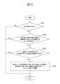
- FIG. 12 is a flowchart showing the processing performed by the recalculation unit 62.
- Coordinates (X, Y) indicate the position of each pixel in the reliability image 150 and the parallax image 130.
- the Y coordinate value indicates the vertical coordinate value of the reliability image 150 and the parallax image 130.
- the X coordinate value indicates the horizontal coordinate value of the reliability image 150 and the parallax image 130.
- step S43 the recalculation unit 62 reads the reliability of the coordinates (X, Y) pixel by pixel from the reliability image 150.
- step S44 the recalculation unit 62 determines whether the reliability is “medium” or “low”. If the reliability is “medium” or “low”, the recalculation unit 62 moves to step S45. If the reliability is not “medium” or “low”, the recalculation unit 62 moves to step S46.
- step S44 The case where the reliability is not "medium” or “low” in step S44 includes the case where the reliability is "high” and the case where it is "invalid". If the reliability is "high”, parallax correction is not necessary, and the recalculation unit 62 moves to step S46. If the reliability is "invalid”, there is a low possibility that a parallax with a "high” reliability will be calculated even if the recalculation is performed, so the recalculation unit 62 proceeds to step S46 to suspend the parallax correction. Transition.
- step S45 the recalculation unit 62 recalculates the parallax of the coordinates (X, Y) using a method different from that of the parallax calculation unit 30.
- the recalculation unit 62 recalculates the parallax using, for example, stereo matching.
- step S47 the recalculation unit 62 determines whether the X coordinate value has reached the maximum value.
- the maximum value of the X coordinate value indicates the coordinate value of the lateral end of the reliability image 150 and the parallax image 130.
- the recalculation unit 62 moves to step S48. If the X coordinate value has not reached the maximum value, the recalculation unit 62 moves to step S43.
- step S49 the recalculation unit 62 determines whether the Y coordinate value has reached the maximum value.
- the maximum value of the Y coordinate value indicates the coordinate value of the end of the reliability image 150 and the parallax image 130 in the vertical direction.
- the recalculation unit 62 ends this process. If the Y coordinate value has not reached the maximum value, the recalculation unit 62 moves to step S42.
- the image processing device 20 of this embodiment includes the parallax calculation unit 30 that calculates the parallax of the images 111 and 112 taken by the plurality of cameras 11 and 12, and the parallax calculation unit 30 that calculates the parallax of the images 111 and 112 that are captured by the plurality of cameras 11 and 12. , a labeling section 40 that assigns a label according to the type of the classified object to each pixel of the object; a reliability calculation section 50 that calculates the reliability of parallax for each assigned label; A parallax correction unit 60 that corrects parallax accordingly.
- the image processing device 20 of the present embodiment calculates the reliability of parallax that changes on a pixel-by-pixel basis depending on the situation of the captured images 111 and 112, and clarifies inaccurate parallax on a pixel-by-pixel basis. Can be done. Therefore, the image processing device 20 of this embodiment can correct parallax according to the situation of the captured images 111 and 112, and therefore can calculate accurate parallax. Therefore, according to this embodiment, it is possible to provide an image processing device that can accurately calculate parallax.
- the parallax correction unit 60 includes a recalculation unit 62 that recalculates parallax whose reliability does not meet the standard using a method different from that of the parallax calculation unit 30.
- the image processing device 20 of the present embodiment can calculate the parallax using a plurality of calculation methods, so even if an error occurs in the parallax due to the characteristics of one calculation method, the image processing device 20 of the present embodiment can calculate the parallax using a plurality of calculation methods. Parallax can be compensated for. Therefore, the image processing device 20 of this embodiment can calculate more accurate parallax.
- the disparity calculation unit 30 calculates the disparity using a neural network model in which the images 111 and 112 are set in the input layer and the disparity is set in the output layer, and performs re-computation.
- the calculation unit 62 recalculates the parallax by stereo matching.
- the image processing device 20 of the present embodiment can compensate for the parallax by stereo matching even if an error occurs in the parallax due to the characteristics of the calculation method using the neural network model. Therefore, the image processing device 20 of this embodiment can calculate more accurate parallax.
- the parallax correction unit 60 has an interpolation unit 61 that interpolates parallax whose reliability does not meet a standard based on the parallax calculated for the previously captured images 111 and 112.
- the image processing device 20 of this embodiment interpolates the parallax from the parallax of the images 111, 112 taken in the past even if the situation of the images 111, 112 taken currently is not suitable for calculating the parallax. It is possible to interpolate the parallax by determining the validity of this. Therefore, the image processing device 20 of this embodiment can calculate more accurate parallax.
- the labeling unit 40 verifies the consistency between the classified object type and the label given to the object based on the parallax.
- the image processing device 20 of the present embodiment is able to add labels more accurately, and therefore can accurately calculate reliability. Therefore, the image processing device 20 of this embodiment can calculate more accurate parallax.
- the reliability calculation unit 50 calculates reliability using a reliability table 51 that shows the correspondence between labels and reliability.
- the image processing device 20 of this embodiment can reduce the amount of calculation for calculating the reliability, and therefore can easily calculate the reliability even with a simple configuration. Therefore, the image processing device 20 of this embodiment can easily calculate accurate parallax.
- the image processing device 20 of this embodiment includes a recognition processing unit 70 that detects objects around the vehicle in which the plurality of cameras 11 and 12 are mounted based on the corrected parallax, reliability, and images 111 and 112. Furthermore, the recognition processing unit 70 changes the size of the object to be detected or the distance to the object depending on the reliability.
- the image processing device 20 of the present embodiment can exclude from detection targets a subject having a parallax whose reliability does not meet the standard. Therefore, the image processing device 20 of this embodiment can calculate accurate parallax and can suppress false detection of objects.
- information on parallax, reliability, and label is input to the recognition processing unit 70 in association with each other for each pixel.
- the image processing device 20 of the present embodiment can reconsider the reliability and label acquired in the pre-object detection stage, thereby improving the accuracy of object detection. Therefore, the image processing device 20 of this embodiment can calculate accurate parallax and improve the accuracy of object detection.
- the present invention is not limited to the above embodiments, and includes various modifications.
- the above embodiments have been described in detail to explain the present invention in an easy-to-understand manner, and the present invention is not necessarily limited to having all the configurations described.
- each of the above-mentioned configurations, functions, processing units, processing means, etc. may be partially or entirely realized by hardware, for example, by designing an integrated circuit. Further, each of the above-mentioned configurations, functions, etc. may be realized by software by a processor interpreting and executing a program for realizing each function. Information such as programs, tapes, and files that implement each function can be stored in a memory, a recording device such as a hard disk, an SSD (solid state drive), or a recording medium such as an IC card, SD card, or DVD.
- a recording device such as a hard disk, an SSD (solid state drive), or a recording medium such as an IC card, SD card, or DVD.
- control lines and information lines are shown that are considered necessary for explanation, and not all control lines and information lines are necessarily shown in the product. In reality, almost all components may be considered to be interconnected.
Landscapes
- Physics & Mathematics (AREA)
- Electromagnetism (AREA)
- Engineering & Computer Science (AREA)
- General Physics & Mathematics (AREA)
- Radar, Positioning & Navigation (AREA)
- Remote Sensing (AREA)
- Image Analysis (AREA)
- Image Processing (AREA)
Abstract
The purpose of the present invention is to provide an image processing device capable of calculating an accurate disparity. An image processing device 20 comprises a disparity calculation unit 30 that calculates a disparity between images 111 and 112 captured by a plurality of cameras 11 and 12, a labeling unit 40 that classifies subjects shown in the images 111 and 112 and assigns, to each pixel of the classified subjects, a label according to the types of the subjects, a reliability calculation unit 50 that calculates the reliability of the disparity for each assigned label, and a disparity correction unit 60 that corrects the disparity according to the calculated reliability.
Description
本発明は、画像処理装置に関する。
The present invention relates to an image processing device.
車両の走行安全性を向上させるため、車両に搭載されたセンサ等によって車両周辺の物体を検知するシステムが研究されている。この種のシステムは、物体に衝突する可能性がある場合には、ドライバに警報を報知したり、自動緊急ブレーキを作動させたりする。
In order to improve the driving safety of vehicles, research is being conducted on systems that detect objects around the vehicle using sensors mounted on the vehicle. This type of system alerts the driver or activates automatic emergency braking if there is a possibility of collision with an object.
車両周辺を監視するセンサとして、ミリ波レーダ、レーザレーダ又はカメラ等がある。カメラの種類としては、単眼カメラ、又は、複数のカメラを有するステレオカメラがある。ステレオカメラは、所定間隔をあけて配置された2つのカメラによって撮影された画像の重複領域の視差を利用し、物体までの距離を計測することができる。したがって、ステレオカメラは、物体との衝突危険度を的確に把握することができる。
There are millimeter wave radars, laser radars, cameras, etc. as sensors that monitor the surroundings of the vehicle. Types of cameras include monocular cameras and stereo cameras having multiple cameras. A stereo camera can measure the distance to an object by using the parallax of an overlapping region of images taken by two cameras arranged at a predetermined interval. Therefore, the stereo camera can accurately grasp the risk of collision with an object.
ステレオカメラは、複数のカメラによって撮影された画像の視差を演算し、演算された視差を距離に変換することから、正確な視差を演算できることが望ましい。正確な視差を演算する技術として、例えば特許文献1がある。
Since the stereo camera calculates the parallax of images taken by multiple cameras and converts the calculated parallax into distance, it is desirable to be able to calculate accurate parallax. As a technique for calculating accurate parallax, there is, for example, Patent Document 1.
特許文献1には、対象物を撮像する撮像手段と、前記撮像手段で撮像した一対の画像の小領域毎に、互いの相関を求めることで対応する領域を特定するステレオマッチング処理を行い、ステレオマッチング処理結果である評価関数、該評価関数に基づいて得られる前記対象物までの距離情報及びその信頼度を示す信頼度情報を取得するステレオ処理手段と、前記信頼度に応じて対象となる小領域の周辺に再探索範囲を設定し、前記再探索範囲内の小領域について求めた前記評価関数に基づいて、前記対象となる小領域について求めた評価関数を修正して修正評価関数を求め、求めた修正評価関数に基づいて距離情報を補正する視差補正手段とを備えたことを特徴とするステレオ画像処理装置が開示されている。
Patent Document 1 discloses that an image capturing means for capturing an image of a target object and a stereo matching process are performed for each small region of a pair of images captured by the image capturing means to identify corresponding regions by determining mutual correlation. stereo processing means for acquiring an evaluation function that is a matching processing result, distance information to the target object obtained based on the evaluation function, and reliability information indicating the reliability thereof; setting a re-search range around the area, and based on the evaluation function calculated for the small area within the re-search range, correcting the evaluation function calculated for the target small area to obtain a modified evaluation function; Disclosed is a stereo image processing device characterized by comprising a parallax correction means for correcting distance information based on the obtained modified evaluation function.
特許文献1に開示された装置は、ステレオマッチングにおいて設定されるマッチングブロック単位で求めた評価関数を修正することによって、視差を補正している。したがって、特許文献1に開示された装置では、撮影された画像の状況によっては、補正された視差であっても大きな誤差を含んでいる可能性があり、改善の余地がある。
The device disclosed in Patent Document 1 corrects parallax by correcting the evaluation function determined for each matching block set in stereo matching. Therefore, in the device disclosed in Patent Document 1, depending on the situation of the captured image, even the corrected parallax may contain a large error, and there is room for improvement.
本発明は、上記に鑑みてなされたものであり、正確な視差を演算することが可能な画像処理装置を提供することを目的とする。
The present invention has been made in view of the above, and an object of the present invention is to provide an image processing device that can accurately calculate parallax.
上記課題を解決するために、本発明の画像処理装置は、複数のカメラによって撮影された画像の視差を演算する視差演算部と、前記画像に写る被写体を分類し、分類された前記被写体の種類に応じたラベルを前記被写体の画素毎に付与するラベリング部と、付与された前記ラベル毎に前記視差の信頼度を算出する信頼度算出部と、算出された前記信頼度に応じて前記視差を補正する視差補正部と、を備えることを特徴とする。
In order to solve the above problems, an image processing device of the present invention includes a parallax calculation unit that calculates the parallax of images captured by a plurality of cameras, and a parallax calculation unit that classifies objects that appear in the images and types of the classified objects. a labeling unit that assigns a label to each pixel of the object according to the label, a reliability calculation unit that calculates the reliability of the parallax for each label assigned, and a reliability calculation unit that calculates the parallax according to the calculated reliability. A parallax correction unit that corrects the parallax.
本発明によれば、正確な視差を演算することが可能な画像処理装置を提供することができる。
上記以外の課題、構成および効果は、以下の実施形態の説明により明らかにされる。 According to the present invention, it is possible to provide an image processing device that can accurately calculate parallax.
Problems, configurations, and effects other than those described above will be made clear by the description of the embodiments below.
以下、本発明の実施形態について図面を用いて説明する。なお、各実施形態において同一の符号を付された構成については、特に言及しない限り、各実施形態において同様の機能を有し、その説明を省略する。
Hereinafter, embodiments of the present invention will be described using the drawings. It should be noted that components designated by the same reference numerals in each embodiment have the same functions in each embodiment unless otherwise specified, and their explanation will be omitted.
図1は、本実施形態の画像処理装置20を備えるステレオカメラ装置1の構成を示す図である。図2は、視差画像130を示す図である。図3は、ラベル画像140を示す図である。図4は、オクルージョン部分241を説明する図である。図5は、信頼度テーブル51を示す図である。図6は、信頼度画像150を示す図である。
FIG. 1 is a diagram showing the configuration of a stereo camera device 1 including an image processing device 20 of this embodiment. FIG. 2 is a diagram showing the parallax image 130. FIG. 3 is a diagram showing the label image 140. FIG. 4 is a diagram illustrating the occlusion portion 241. FIG. 5 is a diagram showing the reliability table 51. FIG. 6 is a diagram showing the reliability image 150.
ステレオカメラ装置1は、車両に搭載され、車両周辺を監視するセンサの一種である。ステレオカメラ装置1は、水平方向に所定間隔をあけて配置された複数のカメラ11,12によって撮影された画像111,112の重複領域の視差を利用して、車両周辺の物体の検知及び物体までの距離計測を行う。
The stereo camera device 1 is a type of sensor that is mounted on a vehicle and monitors the area around the vehicle. The stereo camera device 1 detects objects around the vehicle and measures the distance to the objects by utilizing the parallax of the overlapping areas of images 111, 112 captured by multiple cameras 11, 12 arranged at a predetermined interval in the horizontal direction.
図1に示すステレオカメラ装置1は、左カメラ11及び右カメラ12と、左カメラ11によって撮影された左画像111、及び、右カメラ12によって撮影された右画像112の画像処理等を行う画像処理装置20と、を備える。
The stereo camera device 1 shown in FIG. 1 performs image processing using a left camera 11 and a right camera 12, a left image 111 taken by the left camera 11, and a right image 112 taken by the right camera 12. A device 20 is provided.
画像処理装置20は、例えば、CPU等のプロセッサとROM及びRAM等の記憶装置とを備えたコンピュータによって構成される。画像処理装置20は、ROMに記憶されたプログラムをCPUが実行することによって画像処理装置20の各種機能を実現する。
The image processing device 20 is configured by, for example, a computer including a processor such as a CPU and a storage device such as a ROM and a RAM. The image processing device 20 realizes various functions of the image processing device 20 by the CPU executing programs stored in the ROM.
画像処理装置20は、視差演算部30と、ラベリング部40と、信頼度算出部50と、視差補正部60と、認識処理部70と、を備える。
The image processing device 20 includes a parallax calculation section 30, a labeling section 40, a reliability calculation section 50, a parallax correction section 60, and a recognition processing section 70.
視差演算部30は、左カメラ11及び右カメラ12によって撮影された左画像111及び右画像112の視差を画素毎に演算する。本実施形態の視差演算部30は、ニューラルネットワークモデルを有する。ニューラルネットワークモデルの入力層には、左画像111及び右画像112が設定される。ニューラルネットワークモデルの出力層には、左画像111及び右画像112の視差が設定される。ニューラルネットワークモデルの中間層には、各ニューロンの重みとバイアスと活性化関数とが設定される。ニューラルネットワークモデルは、誤差逆伝播法等を用いて、各ニューロンの重みとバイアスとを機械学習することによって構築されて、視差演算部30に予め組み込まれている。当該機械学習は教師あり学習であってもよい。なお、視差演算部30は、ニューラルネットワークモデル以外の機械学習によって構築されたモデルを有していてもよい。視差演算部30が有するモデルは、例えば、オプティカルフローモデルであってもよい。
The parallax calculation unit 30 calculates the parallax of the left image 111 and the right image 112 captured by the left camera 11 and the right camera 12 for each pixel. The parallax calculation unit 30 of this embodiment has a neural network model. A left image 111 and a right image 112 are set in the input layer of the neural network model. The parallax between the left image 111 and the right image 112 is set in the output layer of the neural network model. In the intermediate layer of the neural network model, weights, biases, and activation functions for each neuron are set. The neural network model is constructed by machine learning the weights and biases of each neuron using error backpropagation, etc., and is installed in the parallax calculation unit 30 in advance. The machine learning may be supervised learning. Note that the parallax calculation unit 30 may have a model constructed by machine learning other than the neural network model. The model included in the parallax calculation unit 30 may be, for example, an optical flow model.
視差演算部30は、演算された視差が各画素に格納された視差画像130を生成する。視差画像130は、例えば図2に示すように、右画像112の各画素に対応する視差が、右画像112の各画素に格納された画像として生成される。図2に示す視差画像130は、色が濃いほど視差が大きく近距離であることを示している。
The parallax calculation unit 30 generates a parallax image 130 in which the calculated parallax is stored in each pixel. The parallax image 130 is generated as an image in which the parallax corresponding to each pixel of the right image 112 is stored in each pixel of the right image 112, as shown in FIG. 2, for example. In the parallax image 130 shown in FIG. 2, the darker the color, the larger the parallax and the closer the distance.
ラベリング部40は、右画像112に写る被写体を分類し、分類された被写体の種類に応じたラベルを被写体の画素毎に付与する。ラベリング部40は、ニューラルネットワークモデルを用いて被写体の分類及びラベルの付与を行うことができる。本実施形態のラベリング部40は、パノプティックセグメンテーション(Panoptic Segmentation)によって、被写体の分類及びラベルの付与を行う。パノプティックセグメンテーションの処理概要は、Kirillovらの論文である”Panoptic Feature Pyramid Networks”,2019 IEEE/CVF Conference on CVPRに紹介されている。ラベリング部40は、当該論文を援用することができる。
The labeling unit 40 classifies the subject appearing in the right image 112 and assigns a label according to the type of the classified subject to each pixel of the subject. The labeling unit 40 can classify objects and assign labels using a neural network model. The labeling unit 40 of this embodiment classifies objects and assigns labels using panoptic segmentation. A processing overview of panoptic segmentation is introduced in the paper by Kirillov et al., “Panoptic Feature Pyramid Networks,” 2019 IEEE/CVF Conference on CVPR. The labeling unit 40 can refer to the paper.
ラベリング部40は、例えば図3に示すように、学習されたラベルの情報に従って、右画像112に写る被写体を、路面210、水溜まり220、側溝230、車両240、車両250、ゼブラゾーン260のように画素単位で分類する。そして、ラベリング部40は、被写体毎に割り当てられたラベルのラベル番号を被写体の画素毎に書き込む。このようにして、ラベリング部40は、各画素にラベル番号が格納されたラベル画像140を生成する。
For example, as shown in FIG. 3, the labeling unit 40 labels the objects in the right image 112 as road surfaces 210, puddles 220, gutters 230, vehicles 240, vehicles 250, and zebra zones 260, according to the learned label information. Classify by pixel. Then, the labeling unit 40 writes the label number of the label assigned to each subject for each pixel of the subject. In this way, the labeling unit 40 generates a label image 140 in which a label number is stored in each pixel.
また、右カメラ12によって撮影されるエリアにおいて左カメラ11には死角になり撮影されない部分が生じる場合がある。このようなオクルージョン部分241では正確な視差が演算できないので、視差が無効であることを明示する必要がある。ラベリング部40は、オクルージョン部分241を特定するために、次のような処理を行う。例えば、図4に示すように、右画像112及び左画像111では、車両240と車両250との重なり具合が異なっており、オクルージョン部分241が左画像111には撮影されていないとする。この場合、ラベリング部40は、車両240及び車両250の視差を比較して、視差が大きい被写体である車両240の右側に存在する領域をオクルージョン部分241として特定する。オクルージョン部分241の横幅は、車両240の視差と車両250の視差との差分の画素数となる。
Furthermore, in the area photographed by the right camera 12, there may be a blind spot for the left camera 11 and a portion that is not photographed. Since accurate parallax cannot be calculated in such an occlusion part 241, it is necessary to clearly indicate that the parallax is invalid. The labeling unit 40 performs the following processing in order to identify the occlusion portion 241. For example, as shown in FIG. 4, it is assumed that the right image 112 and the left image 111 have different degrees of overlap between the vehicles 240 and 250, and the occlusion portion 241 is not captured in the left image 111. In this case, the labeling unit 40 compares the parallaxes of the vehicle 240 and the vehicle 250, and identifies the area on the right side of the vehicle 240, which is the subject with a large parallax, as the occlusion portion 241. The width of the occlusion portion 241 is the number of pixels that is the difference between the parallax of the vehicle 240 and the parallax of the vehicle 250.
また、ラベリング部40は、視差演算部30により演算された視差に基づいて、分類された被写体の種類と当該被写体に付与されたラベルとの整合性を検証することができる。例えば、人物像の写真が貼られた看板が被写体の場合、被写体を構成する画素群の各視差は、当該画素群において略一定又は線形的に変化する値を示し、被写体は平面であると認識される。一方、実際の人物が被写体の場合、被写体を構成する画素群の各視差は、当該画素群において非線形的に変化する値を示し、被写体は立体であると認識される。このようなことから、ラベリング部40は、右画像112だけでなく視差画像130を用いることによって、分類された被写体の種類と当該被写体に付与されたラベルとの整合性を検証することができる。
The labeling unit 40 can also verify the consistency between the type of the classified subject and the label assigned to the subject based on the parallax calculated by the parallax calculation unit 30. For example, if the subject is a signboard with a picture of a person attached to it, the parallax of the pixels that make up the subject indicates a value that is approximately constant or changes linearly in the pixel group, and the subject is recognized as being flat. On the other hand, if the subject is an actual person, the parallax of the pixels that make up the subject indicates a value that changes nonlinearly in the pixel group, and the subject is recognized as being three-dimensional. For this reason, the labeling unit 40 can verify the consistency between the type of the classified subject and the label assigned to the subject by using the parallax image 130 in addition to the right image 112.
信頼度算出部50は、ラベリング部40により付与されたラベル毎に視差の信頼度を算出する。信頼度は、視差の値に含まれる誤差の大きさを数値化した指標である。視差の値に含まれる誤差が小さくなると、信頼度は高くなる。本実施形態では、視差の値に含まれる誤差が20%以上なら信頼度は「低」、当該誤差が10%以上20%未満なら信頼度は「中」、当該誤差が10%未満なら信頼度は「高」であるとする。
The reliability calculation unit 50 calculates the reliability of parallax for each label given by the labeling unit 40. The reliability is an index that quantifies the magnitude of the error included in the parallax value. The smaller the error included in the parallax value, the higher the reliability. In this embodiment, the reliability is "low" if the error included in the parallax value is 20% or more, the reliability is "medium" if the error is 10% or more and less than 20%, and the reliability is "medium" if the error is less than 10%. is "high".
画像111,112画像が撮影された車両周辺の状況によっては、視差に誤差が生じて正確な視差が演算されない場合がある。不正確な視差をそのまま用いて認識処理を行うと、物体の誤検知又は検知不能となる事態が生じる可能性がある。そこで、信頼度算出部50は、視差が不正確であると想定される被写体を明確化するために、信頼度を算出する。
Depending on the circumstances surrounding the vehicle where the images 111 and 112 were taken, an error may occur in the parallax and accurate parallax may not be calculated. If recognition processing is performed using inaccurate parallax as is, a situation may occur where an object is erroneously detected or cannot be detected. Therefore, the reliability calculation unit 50 calculates the reliability in order to clarify the subject whose parallax is assumed to be inaccurate.
信頼度算出部50は、予め作成された信頼度テーブル51を用いて視差の信頼度を算出する。信頼度テーブル51は、図5に示すように、ラベルと信頼度との対応関係を示すテーブルである。図5に示す信頼度テーブル51において、信頼度の項目が「0」の場合は信頼度が「無効」であることを示し、信頼度の項目が「1」の場合は信頼度が「低」であることを示し、信頼度の項目が「2」の場合は信頼度が「中」であることを示し、信頼度の項目が「3」の場合は信頼度が「高」であることを示す。
The reliability calculation unit 50 calculates the reliability of the disparity using a reliability table 51 created in advance. The reliability table 51 is a table showing the correspondence between labels and reliability, as shown in FIG. 5. In the reliability table 51 shown in FIG. 5, a reliability item of "0" indicates that the reliability is "invalid", a reliability item of "1" indicates that the reliability is "low", a reliability item of "2" indicates that the reliability is "medium", and a reliability item of "3" indicates that the reliability is "high".
信頼度算出部50は、信頼度テーブル51を参照し、ラベリング部40によって付与されたラベルに対応する信頼度を特定する。そして、信頼度算出部50は、特定された信頼度を、当該ラベルが付与された被写体の画素毎に書き込む。このようにして、信頼度算出部50は、図6に示すような、各画素にラベル番号及び信頼度が格納された信頼度画像150を生成する。
The reliability calculation unit 50 refers to the reliability table 51 and identifies the reliability corresponding to the label assigned by the labeling unit 40. The reliability calculation unit 50 then writes the identified reliability for each pixel of the subject to which the label is assigned. In this way, the reliability calculation unit 50 generates a reliability image 150 in which a label number and a reliability are stored for each pixel, as shown in FIG. 6.
視差補正部60は、信頼度算出部50により算出された信頼度に応じて視差を補正する。視差補正部60は、補間部61と、再演算部62と、を有する。
The parallax correction unit 60 corrects parallax according to the reliability calculated by the reliability calculation unit 50. The parallax correction unit 60 includes an interpolation unit 61 and a recalculation unit 62.
補間部61は、過去に撮影された画像111,112に対して演算された視差に基づいて、信頼度が基準に満たない視差を補間する。補間部61は、信頼度が基準に満たない視差を補間することによって、視差画像130を補正することができる。本実施形態の補間部61は、過去に撮影された画像111,112に対して演算された視差に基づいて信頼度が「低」又は「無効」の視差を補間するか否かを判定し、補間すると判定された場合には信頼度が「高」の視差を用いて「低」又は「無効」の視差を補間する。例えば、現在撮影された画像111,112に対して演算された信頼度が「低」又は「無効」のエリアが、過去に撮影された画像111,112では信頼度が「高」と演算されているとする。この場合、本実施形態の補間部61は、当該エリアの信頼度が「低」又は「無効」の視差を補間すると判定し、当該エリアに隣接する信頼度が「高」の視差を用いて、当該エリアの信頼度が「低」又は「無効」の視差を補間する。
The interpolation unit 61 interpolates the parallax whose reliability does not meet the standard based on the parallax calculated for the images 111 and 112 taken in the past. The interpolation unit 61 can correct the parallax image 130 by interpolating parallaxes whose reliability does not meet the standard. The interpolation unit 61 of the present embodiment determines whether or not to interpolate parallaxes whose reliability is "low" or "invalid" based on the parallaxes calculated for images 111 and 112 taken in the past, When it is determined that interpolation is to be performed, a parallax with a "high" reliability is used to interpolate a parallax with a "low" or "invalid" reliability. For example, an area where the reliability calculated for the images 111 and 112 taken currently is "low" or "invalid" is calculated as "high" for the images 111 and 112 taken in the past. Suppose there is. In this case, the interpolation unit 61 of the present embodiment determines to interpolate the parallax of which the reliability of the area is "low" or "invalid", and uses the parallax of which the reliability is "high" adjacent to the area, Interpolates parallaxes whose reliability in the area is "low" or "invalid".
再演算部62は、信頼度が基準に満たない視差を、視差演算部30とは異なる方式を用いて再演算する。再演算部62は、信頼度が基準に満たない視差を再演算された視差と置換することによって、視差画像130を補正することができる。本実施形態の再演算部62は、信頼度が「中」又は「低」である視差を、例えば、ステレオマッチングによって再演算する。本実施形態の再演算部62は、補間部61によって補間後の視差を再演算の対象としてもよい。なお、視差演算部30がステレオマッチングによって視差を演算する場合、再演算部62はニューラルネットワークモデルを用いて視差を再演算してもよい。
The recalculation unit 62 recalculates the parallax whose reliability does not meet the standard using a method different from that of the parallax calculation unit 30. The recalculation unit 62 can correct the parallax image 130 by replacing the parallax whose reliability does not meet the standard with the recalculated parallax. The recalculation unit 62 of this embodiment recalculates the parallax whose reliability is "medium" or "low" by, for example, stereo matching. The recalculation unit 62 of this embodiment may use the parallax interpolated by the interpolation unit 61 as a target for recalculation. Note that when the parallax calculation unit 30 calculates the parallax by stereo matching, the recalculation unit 62 may recalculate the parallax using a neural network model.
認識処理部70は、視差補正部60により補正された視差、信頼度算出部50により算出された信頼度、及び、画像111,112に基づいて、車両周辺の物体を検知する。具体的には、認識処理部70は、補正された視差画像130、信頼度画像150、左画像111及び右画像112を用いて、車両周辺の物体を検知する。
The recognition processing unit 70 detects objects around the vehicle based on the parallax corrected by the parallax correction unit 60, the reliability calculated by the reliability calculation unit 50, and the images 111 and 112. Specifically, the recognition processing unit 70 uses the corrected parallax image 130, reliability image 150, left image 111, and right image 112 to detect objects around the vehicle.
例えば、信頼度が「高」の路面のエリアは、正確な視差を有しており、路面上の小さな被写体も検知可能である。一方、信頼度が「低」の路面のエリアは、路面上の小さな被写体と視差に含まれる誤差との区別が困難である。そこで、信頼度が「低」のエリアにおいて誤検知を回避するために、認識処理部70は、検知対象とする被写体の大きさ又は被写体までの距離を、信頼度に応じて変更する。例えば、認識処理部70は、信頼度が「低」のエリアでは、路面上の被写体のうち、路面の視差に含まれる誤差よりも大きい背丈を有する被写体を検知対象とする。被写体の背丈が高いことは、当該被写体として撮影された物体が、カメラ11,12に近い位置にあるか、所定値より高い背丈を有するかの場合である。よって、認識処理部70は、信頼度が「低」の路面のエリアでは、路面の視差に含まれる誤差よりも大きい背丈を有する被写体を検知対象とし、信頼度が「高」の路面のエリアでは、信頼度が「高」の路面のエリアよりも小さい背丈を有する被写体まで検知対象とする。このようにして、認識処理部70は、検知対象とする被写体の大きさ又は被写体までの距離を、信頼度に応じて変更することができる。物体検知自体の手法については、認識処理部70は公知の手法を採用することができる。
For example, a road surface area with "high" reliability has accurate parallax, and even small objects on the road surface can be detected. On the other hand, in the area of the road surface where the reliability is "low", it is difficult to distinguish between a small object on the road surface and an error included in the parallax. Therefore, in order to avoid false detection in areas where the reliability is "low", the recognition processing unit 70 changes the size of the object to be detected or the distance to the object according to the reliability. For example, in an area where the reliability is "low", the recognition processing unit 70 detects, among objects on the road, objects whose height is greater than the error included in the parallax of the road. A subject is tall if the object photographed as the subject is located close to the cameras 11 and 12 or has a height higher than a predetermined value. Therefore, the recognition processing unit 70 detects a subject whose height is larger than the error included in the parallax of the road surface in the road surface area where the reliability is "low", and detects the object whose height is larger than the error included in the road surface parallax in the road surface area where the reliability is "high". , subjects whose height is smaller than the road surface area with "high" reliability are also detected. In this way, the recognition processing unit 70 can change the size of the object to be detected or the distance to the object depending on the reliability. As for the method of object detection itself, the recognition processing unit 70 can employ a known method.
なお、認識処理部70には、視差画像130及び信頼度画像150が画素毎に互いに対応付けて入力される。すなわち、認識処理部70には、視差、信頼度及びラベルの情報が画素毎に互いに対応付けて入力される。これにより、認識処理部70が、例えば信頼度が基準に満たない画素に対して事後的にラベルを再付与したり、事後的に信頼度を再算出したりすることができる。すなわち、認識処理部70は、物体検知の前段階で取得されるデータ(信頼度又はラベル)を改めて見直すことができ、物体検知の確度を向上させることができる。
Note that the parallax image 130 and the reliability image 150 are input to the recognition processing unit 70 in a manner that corresponds to each other pixel by pixel. That is, parallax, reliability, and label information are input to the recognition processing unit 70 in association with each other for each pixel. Thereby, the recognition processing unit 70 can, for example, re-label a pixel whose reliability does not meet the standard after the fact or recalculate the reliability after the fact. That is, the recognition processing unit 70 can reconsider the data (reliability or label) acquired at the stage before object detection, and can improve the accuracy of object detection.
図7は、画像処理装置20の動作を示すフローチャートである。
FIG. 7 is a flowchart showing the operation of the image processing device 20.
ステップS11において、画像処理装置20の視差演算部30は、左画像111及び右画像112から視差画像130を生成する。
In step S11, the parallax calculation unit 30 of the image processing device 20 generates a parallax image 130 from the left image 111 and the right image 112.
ステップS12において、画像処理装置20のラベリング部40は、右画像112及び視差画像130を用いて被写体を分類し、被写体の画素毎にラベルを付与してラベル画像140を生成する。
In step S12, the labeling unit 40 of the image processing device 20 classifies the subject using the right image 112 and the parallax image 130, and generates a label image 140 by assigning a label to each pixel of the subject.
ステップS13において、画像処理装置20の信頼度算出部50は、信頼度テーブル51を用いてラベル毎に視差の信頼度を算出し、信頼度画像150を生成する。
In step S13, the reliability calculation unit 50 of the image processing device 20 calculates the reliability of parallax for each label using the reliability table 51, and generates the reliability image 150.
ステップS14において、画像処理装置20の視差補正部60は、信頼度が基準に満たない視差を補正する。
In step S14, the parallax correction unit 60 of the image processing device 20 corrects parallaxes whose reliability does not meet the standard.
ステップS15において、画像処理装置20の認識処理部70は、視差画像130、信頼度画像150、右画像112及び左画像111を用いて物体検知を行う。その後、画像処理装置20は、物体検知結果に応じた処理として、例えば警報の報知又は自動緊急ブレーキの作動を促す信号を車両制御装置に送信する処理等を行い、本処理を終了する。
In step S15, the recognition processing unit 70 of the image processing device 20 performs object detection using the parallax image 130, the reliability image 150, the right image 112, and the left image 111. Thereafter, the image processing device 20 performs a process according to the object detection result, such as transmitting a signal to the vehicle control device to issue an alarm or activate an automatic emergency brake, and ends this process.
図8は、信頼度算出部50によって行われる処理を示すフローチャートである。図9は、信頼度画像150の一画素に書き込まれるデータの構成例を示す図である。
FIG. 8 is a flowchart showing the processing performed by the reliability calculation unit 50. FIG. 9 is a diagram showing an example of the structure of data written to one pixel of the reliability image 150.
ステップS21において、信頼度算出部50は、ラベル画像140及び信頼度画像150にアクセス(読み込み及び書き込み)するための座標(X,Y)のY座標値を初期化する(Y=0)。座標(X,Y)は、ラベル画像140及び信頼度画像150の各画素の位置を示す。Y座標値は、ラベル画像140及び信頼度画像150の縦方向の座標値を示す。
In step S21, the reliability calculation unit 50 initializes the Y coordinate value of the coordinates (X, Y) for accessing (reading and writing) the label image 140 and reliability image 150 (Y=0). Coordinates (X, Y) indicate the position of each pixel in the label image 140 and reliability image 150. The Y coordinate value indicates the vertical coordinate value of the label image 140 and the reliability image 150.
ステップS22において、信頼度算出部50は、座標(X,Y)のX座標値を初期化する(X=0)。X座標値は、ラベル画像140及び信頼度画像150の横方向の座標値を示す。
In step S22, the reliability calculation unit 50 initializes the X coordinate value of the coordinates (X, Y) (X=0). The X coordinate value indicates the horizontal coordinate value of the label image 140 and the reliability image 150.
ステップS23において、信頼度算出部50は、ラベル画像140から座標(X,Y)のラベル番号を一画素ずつ読み込む。
In step S23, the reliability calculation unit 50 reads the label number of the coordinates (X, Y) from the label image 140 one pixel at a time.
ステップS24において、信頼度算出部50は、ラベル番号に対応付けられた視差の信頼度を信頼度テーブル51から取得する。
In step S24, the reliability calculation unit 50 obtains the reliability of the parallax associated with the label number from the reliability table 51.
ステップS25において、信頼度算出部50は、ラベル番号及び信頼度を信頼度画像150の座標(X,Y)に書き込む。この時に書き込まれるデータは、例えば図9に示すように構成される。図9に例では、書き込まれるデータは、一画素が8ビットであり、bit0からbit3までは信頼度によって構成され、bit4からbit7まではラベル番号によって構成される。
In step S25, the reliability calculation unit 50 writes the label number and reliability at the coordinates (X, Y) of the reliability image 150. The data written at this time is structured as shown in FIG. 9, for example. In the example shown in FIG. 9, one pixel of data to be written has 8 bits, bits 0 to 3 are composed of reliability levels, and bits 4 to 7 are composed of label numbers.
ステップS26において、信頼度算出部50は、X座標値を更新する(X=X+1)。
In step S26, the reliability calculation unit 50 updates the X coordinate value (X=X+1).
ステップS27において、信頼度算出部50は、X座標値が最大値に到達したか否かを判定する。X座標値の最大値は、ラベル画像140及び信頼度画像150の横方向端部の座標値を示す。X座標値が最大値に到達した場合、信頼度算出部50は、ステップS28に移行する。X座標値が最大値に到達していない場合、信頼度算出部50は、ステップS23に移行する。
In step S27, the reliability calculation unit 50 determines whether the X coordinate value has reached the maximum value. The maximum value of the X coordinate value indicates the coordinate value of the horizontal end of the label image 140 and the reliability image 150. When the X coordinate value reaches the maximum value, the reliability calculation unit 50 moves to step S28. If the X coordinate value has not reached the maximum value, the reliability calculation unit 50 moves to step S23.
ステップS28において、信頼度算出部50は、Y座標値を更新する(Y=Y+1)。
In step S28, the reliability calculation unit 50 updates the Y coordinate value (Y=Y+1).
ステップS29において、信頼度算出部50は、Y座標値が最大値に到達したか否かを判定する。Y座標値の最大値は、ラベル画像140及び信頼度画像150の縦方向端部の座標値を示す。Y座標値が最大値に到達した場合、信頼度算出部50は、本処理を終了する。Y座標値が最大値に到達していない場合、信頼度算出部50は、ステップS22に移行する。
In step S29, the reliability calculation unit 50 determines whether the Y coordinate value has reached the maximum value. The maximum value of the Y coordinate value indicates the coordinate value of the vertical end of the label image 140 and the reliability image 150. When the Y coordinate value reaches the maximum value, the reliability calculation unit 50 ends this process. If the Y coordinate value has not reached the maximum value, the reliability calculation unit 50 moves to step S22.
図10は、補間部61によって行われる処理を示すフローチャートである。図11は、図10に示すステップS34を説明する図である。図10及び図11では、先行車と自車との間の路面を補間部61の処理対象とする場合を例に挙げて説明する。
FIG. 10 is a flowchart showing the processing performed by the interpolation unit 61. FIG. 11 is a diagram illustrating step S34 shown in FIG. 10. In FIGS. 10 and 11, an example will be described in which a road surface between the preceding vehicle and the host vehicle is processed by the interpolation unit 61.
ステップS31において、補間部61は、信頼度画像150において先行車が有るか否かを判定する。先行車が有る場合、補間部61は、ステップS32に移行する。先行車が無い場合、補間部61は、本処理を終了する。
In step S31, the interpolation unit 61 determines whether there is a preceding vehicle in the reliability image 150. If there is a preceding vehicle, the interpolation unit 61 moves to step S32. If there is no preceding vehicle, the interpolation unit 61 ends this process.
ステップS32において、補間部61は、先行車と自車との間の路面に信頼度が「低」又は「無効」のエリアが有るか否かを判定する。信頼度が「低」又は「無効」のエリアが有る場合、補間部61は、ステップS33に移行する。信頼度が「低」又は「無効」のエリアが無い場合、補間部61は、本処理を終了する。
In step S32, the interpolation unit 61 determines whether there is an area where the reliability is "low" or "invalid" on the road surface between the preceding vehicle and the host vehicle. If there is an area with "low" or "invalid" reliability, the interpolation unit 61 moves to step S33. If there is no area with "low" or "invalid" reliability, the interpolation unit 61 ends this process.
ステップS33において、補間部61は、信頼度が「低」又は「無効」のエリアを走行する先行車が写った過去の画像(ラベル画像140又は信頼度画像150)が有るか否かを判定する。先行車が写った過去の画像が有る場合、補間部61は、ステップS34に移行する。先行車が写った過去の画像が無い場合、補間部61は、本処理を終了する。
In step S33, the interpolation unit 61 determines whether there is a past image (label image 140 or reliability image 150) that shows a preceding vehicle traveling in an area with a "low" or "invalid" reliability. If there is a past image that shows a preceding vehicle, the interpolation unit 61 proceeds to step S34. If there is no past image that shows a preceding vehicle, the interpolation unit 61 ends this process.
ステップS34において、補間部61は、信頼度が「低」又は「無効」の視差を、信頼度が「高」である路面の視差を用いて、ラスター単位で補間する。ステップS34の後、補間部61は、本処理を終了する。
In step S34, the interpolation unit 61 interpolates the parallax whose reliability is "low" or "invalid" in units of raster using the parallax of the road surface whose reliability is "high". After step S34, the interpolation unit 61 ends this process.
例えば、図11に示すように、先行車と自車との間の路面に信頼度が「低」又は「無効」のエリア310(例えば水溜まりのエリア)が有ったとする。この場合、補間部61は、エリア310に隣接する信頼度が「高」である路面300の視差を用いて補間する。具体的には、補間部61は、エリア310を構成する画素311~314の視差B~Eを、画素311に対して横方向に隣接する路面300の画素301の視差Aと、画素314に対して横方向に隣接する路面300の画素302の視差Fとを用いて補間する。
For example, as shown in FIG. 11, it is assumed that there is an area 310 (for example, a puddle area) where the reliability is "low" or "invalid" on the road surface between the preceding vehicle and the host vehicle. In this case, the interpolation unit 61 performs interpolation using the parallax of the road surface 300 adjacent to the area 310 and having a "high" reliability. Specifically, the interpolation unit 61 converts the parallaxes B to E of the pixels 311 to 314 constituting the area 310 to the parallax A of the pixel 301 of the road surface 300 adjacent to the pixel 311 in the horizontal direction, and the parallax of the pixel 314. Interpolation is performed using the parallax F of the pixels 302 of the road surface 300 that are laterally adjacent to each other.
まず、補間部61は、式(1)を計算する。
補間値=(視差F-視差A)/(画素302のX座標値-画素301のX座標値)…(1) First, theinterpolation unit 61 calculates equation (1).
Interpolated value = (parallax F - parallax A) / (X coordinate value of pixel 302 - X coordinate value of pixel 301)...(1)
補間値=(視差F-視差A)/(画素302のX座標値-画素301のX座標値)…(1) First, the
Interpolated value = (parallax F - parallax A) / (X coordinate value of pixel 302 - X coordinate value of pixel 301)...(1)
次に、補間部61は、式(2)を計算する。
視差B=視差A+補間値×(画素311のX座標値-画素301のX座標値)…(2) Next, theinterpolation unit 61 calculates equation (2).
Parallax B = Parallax A + Interpolation value × (X coordinate value of pixel 311 - X coordinate value of pixel 301)...(2)
視差B=視差A+補間値×(画素311のX座標値-画素301のX座標値)…(2) Next, the
Parallax B = Parallax A + Interpolation value × (X coordinate value of pixel 311 - X coordinate value of pixel 301)...(2)
視差C~Eについても、式(2)と同様に計算する。以上の計算をラスター単位で行うことによって、補間部61は、信頼度が「低」又は「無効」の視差を、信頼度が「高」である路面の視差を用いて補間することができる。
Parallaxes C to E are also calculated in the same manner as in equation (2). By performing the above calculation on a raster basis, the interpolation unit 61 can interpolate the parallax whose reliability is "low" or "invalid" using the parallax of the road surface whose reliability is "high".
図12は、再演算部62によって行われる処理を示すフローチャートである。
FIG. 12 is a flowchart showing the processing performed by the recalculation unit 62.
ステップS41において、再演算部62は、信頼度画像150及び視差画像130にアクセス(読み込み及び書き込み)するための座標(X,Y)のY座標値を初期化する(Y=0)。座標(X,Y)は、信頼度画像150及び視差画像130の各画素の位置を示す。Y座標値は、信頼度画像150及び視差画像130の縦方向の座標値を示す。
In step S41, the recalculation unit 62 initializes the Y coordinate value of the coordinates (X, Y) for accessing (reading and writing) the reliability image 150 and the parallax image 130 (Y=0). Coordinates (X, Y) indicate the position of each pixel in the reliability image 150 and the parallax image 130. The Y coordinate value indicates the vertical coordinate value of the reliability image 150 and the parallax image 130.
ステップS42において、再演算部62は、座標(X,Y)のX座標値を初期化する(X=0)。X座標値は、信頼度画像150及び視差画像130の横方向の座標値を示す。
In step S42, the recalculation unit 62 initializes the X coordinate value of the coordinates (X, Y) (X=0). The X coordinate value indicates the horizontal coordinate value of the reliability image 150 and the parallax image 130.
ステップS43において、再演算部62は、信頼度画像150から座標(X,Y)の信頼度を一画素ずつ読み込む。
In step S43, the recalculation unit 62 reads the reliability of the coordinates (X, Y) pixel by pixel from the reliability image 150.
ステップS44において、再演算部62は、信頼度が「中」又は「低」であるか否かを判定する。信頼度が「中」又は「低」である場合、再演算部62は、ステップS45に移行する。信頼度が「中」又は「低」でない場合、再演算部62は、ステップS46に移行する。
In step S44, the recalculation unit 62 determines whether the reliability is "medium" or "low". If the reliability is "medium" or "low", the recalculation unit 62 moves to step S45. If the reliability is not "medium" or "low", the recalculation unit 62 moves to step S46.
ステップS44において信頼度が「中」又は「低」でない場合とは、信頼度が「高」である場合と「無効」である場合とを含む。信頼度が「高」である場合は視差の補正が不要であるので、再演算部62は、ステップS46に移行する。信頼度が「無効」である場合は再演算しても信頼度が「高」の視差が演算される可能性が低いので、再演算部62は、視差の補正を保留するべく、ステップS46に移行する。なお、信頼度が「無効」と算出された視差を有する画素についても、次回撮影される画像111,112において信頼度が「高」の視差が演算される可能性が十分に有るので、再演算部62が視差の補正を保留しても問題にはならない。
The case where the reliability is not "medium" or "low" in step S44 includes the case where the reliability is "high" and the case where it is "invalid". If the reliability is "high", parallax correction is not necessary, and the recalculation unit 62 moves to step S46. If the reliability is "invalid", there is a low possibility that a parallax with a "high" reliability will be calculated even if the recalculation is performed, so the recalculation unit 62 proceeds to step S46 to suspend the parallax correction. Transition. Note that even for pixels with parallaxes whose reliability is calculated as "invalid," there is a good possibility that parallaxes with "high" reliability will be calculated in images 111 and 112 to be captured next time, so the recalculation is necessary. There is no problem even if the unit 62 suspends parallax correction.
ステップS45において、再演算部62は、座標(X,Y)の視差を、視差演算部30とは異なる方式を用いて再演算する。視差演算部30がニューラルネットワークモデルを用いて視差を演算する場合、再演算部62は、例えばステレオマッチングによって視差を再演算する。
In step S45, the recalculation unit 62 recalculates the parallax of the coordinates (X, Y) using a method different from that of the parallax calculation unit 30. When the parallax calculation unit 30 calculates the parallax using a neural network model, the recalculation unit 62 recalculates the parallax using, for example, stereo matching.
ステップS46において、再演算部62は、X座標値を更新する(X=X+1)。
In step S46, the recalculation unit 62 updates the X coordinate value (X=X+1).
ステップS47において、再演算部62は、X座標値が最大値に到達したか否かを判定する。X座標値の最大値は、信頼度画像150及び視差画像130の横方向端部の座標値を示す。X座標値が最大値に到達した場合、再演算部62は、ステップS48に移行する。X座標値が最大値に到達していない場合、再演算部62は、ステップS43に移行する。
In step S47, the recalculation unit 62 determines whether the X coordinate value has reached the maximum value. The maximum value of the X coordinate value indicates the coordinate value of the lateral end of the reliability image 150 and the parallax image 130. When the X coordinate value reaches the maximum value, the recalculation unit 62 moves to step S48. If the X coordinate value has not reached the maximum value, the recalculation unit 62 moves to step S43.
ステップS48において、再演算部62は、Y座標値を更新する(Y=Y+1)。
In step S48, the recalculation unit 62 updates the Y coordinate value (Y=Y+1).
ステップS49において、再演算部62は、Y座標値が最大値に到達したか否かを判定する。Y座標値の最大値は、信頼度画像150及び視差画像130の縦方向端部の座標値を示す。Y座標値が最大値に到達した場合、再演算部62は、本処理を終了する。Y座標値が最大値に到達していない場合、再演算部62は、ステップS42に移行する。
In step S49, the recalculation unit 62 determines whether the Y coordinate value has reached the maximum value. The maximum value of the Y coordinate value indicates the coordinate value of the end of the reliability image 150 and the parallax image 130 in the vertical direction. When the Y coordinate value reaches the maximum value, the recalculation unit 62 ends this process. If the Y coordinate value has not reached the maximum value, the recalculation unit 62 moves to step S42.
以上のように、本実施形態の画像処理装置20は、複数のカメラ11,12によって撮影された画像111,112の視差を演算する視差演算部30と、画像111,112に写る被写体を分類し、分類された被写体の種類に応じたラベルを被写体の画素毎に付与するラベリング部40と、付与されたラベル毎に視差の信頼度を算出する信頼度算出部50と、算出された信頼度に応じて視差を補正する視差補正部60と、を備える。
As described above, the image processing device 20 of this embodiment includes the parallax calculation unit 30 that calculates the parallax of the images 111 and 112 taken by the plurality of cameras 11 and 12, and the parallax calculation unit 30 that calculates the parallax of the images 111 and 112 that are captured by the plurality of cameras 11 and 12. , a labeling section 40 that assigns a label according to the type of the classified object to each pixel of the object; a reliability calculation section 50 that calculates the reliability of parallax for each assigned label; A parallax correction unit 60 that corrects parallax accordingly.
これにより、本実施形態の画像処理装置20は、撮影された画像111,112の状況に応じて変化する視差の信頼度を画素単位で算出し、不正確な視差を画素単位で明確化することができる。したがって、本実施形態の画像処理装置20は、撮影された画像111,112の状況に応じて視差を補正することができるので、正確な視差を演算することができる。よって、本実施形態によれば、正確な視差を演算することが可能な画像処理装置を提供することができる。
As a result, the image processing device 20 of the present embodiment calculates the reliability of parallax that changes on a pixel-by-pixel basis depending on the situation of the captured images 111 and 112, and clarifies inaccurate parallax on a pixel-by-pixel basis. Can be done. Therefore, the image processing device 20 of this embodiment can correct parallax according to the situation of the captured images 111 and 112, and therefore can calculate accurate parallax. Therefore, according to this embodiment, it is possible to provide an image processing device that can accurately calculate parallax.
更に、本実施形態の画像処理装置20において、視差補正部60は、信頼度が基準に満たない視差を、視差演算部30とは異なる方式を用いて再演算する再演算部62を有する。
Furthermore, in the image processing device 20 of the present embodiment, the parallax correction unit 60 includes a recalculation unit 62 that recalculates parallax whose reliability does not meet the standard using a method different from that of the parallax calculation unit 30.
これにより、本実施形態の画像処理装置20は、複数の演算方式によって視差を演算することができるので、一方の演算方式の特性に起因して視差に誤差が生じても、他方の演算方式によって視差を補償することができる。したがって、本実施形態の画像処理装置20は、更に正確な視差を演算することができる。
As a result, the image processing device 20 of the present embodiment can calculate the parallax using a plurality of calculation methods, so even if an error occurs in the parallax due to the characteristics of one calculation method, the image processing device 20 of the present embodiment can calculate the parallax using a plurality of calculation methods. Parallax can be compensated for. Therefore, the image processing device 20 of this embodiment can calculate more accurate parallax.
更に、本実施形態の画像処理装置20において、視差演算部30は、画像111,112が入力層に設定されると共に視差が出力層に設定されたニューラルネットワークモデルを用いて視差を演算し、再演算部62は、ステレオマッチングによって視差を再演算する。
Furthermore, in the image processing device 20 of the present embodiment, the disparity calculation unit 30 calculates the disparity using a neural network model in which the images 111 and 112 are set in the input layer and the disparity is set in the output layer, and performs re-computation. The calculation unit 62 recalculates the parallax by stereo matching.
これにより、本実施形態の画像処理装置20は、ニューラルネットワークモデルを用いた演算方式の特性に起因して視差に誤差が生じても、ステレオマッチングによって視差を補償することができる。したがって、本実施形態の画像処理装置20は、更に正確な視差を演算することができる。
Thereby, the image processing device 20 of the present embodiment can compensate for the parallax by stereo matching even if an error occurs in the parallax due to the characteristics of the calculation method using the neural network model. Therefore, the image processing device 20 of this embodiment can calculate more accurate parallax.
更に、本実施形態の画像処理装置20において、視差補正部60は、過去に撮影された画像111,112に対して演算された視差に基づいて、信頼度が基準に満たない視差を補間する補間部61を有する。
Furthermore, in the image processing device 20 of this embodiment, the parallax correction unit 60 has an interpolation unit 61 that interpolates parallax whose reliability does not meet a standard based on the parallax calculated for the previously captured images 111 and 112.
これにより、本実施形態の画像処理装置20は、現在撮影された画像111,112の状況が視差の演算に適さなくても、過去に撮影された画像111,112の視差から、視差を補間することの妥当性を判断して視差を補間することができる。したがって、本実施形態の画像処理装置20は、更に正確な視差を演算することができる。
Thereby, the image processing device 20 of this embodiment interpolates the parallax from the parallax of the images 111, 112 taken in the past even if the situation of the images 111, 112 taken currently is not suitable for calculating the parallax. It is possible to interpolate the parallax by determining the validity of this. Therefore, the image processing device 20 of this embodiment can calculate more accurate parallax.
更に、本実施形態の画像処理装置20において、ラベリング部40は、視差に基づいて、分類された被写体の種類と当該被写体に付与されたラベルとの整合性を検証する。
Furthermore, in the image processing device 20 of the present embodiment, the labeling unit 40 verifies the consistency between the classified object type and the label given to the object based on the parallax.
これにより、本実施形態の画像処理装置20は、更に正確にラベルを付与することができるので、正確に信頼度を算出することができる。したがって、本実施形態の画像処理装置20は、更に正確な視差を演算することができる。
As a result, the image processing device 20 of the present embodiment is able to add labels more accurately, and therefore can accurately calculate reliability. Therefore, the image processing device 20 of this embodiment can calculate more accurate parallax.
更に、本実施形態の画像処理装置20において、信頼度算出部50は、ラベルと信頼度との対応関係を示す信頼度テーブル51を用いて信頼度を算出する。
Furthermore, in the image processing device 20 of this embodiment, the reliability calculation unit 50 calculates reliability using a reliability table 51 that shows the correspondence between labels and reliability.
これにより、本実施形態の画像処理装置20は、信頼度を算出するための計算量を削減することができるので、簡易な構成であっても信頼度を容易に算出することができる。したがって、本実施形態の画像処理装置20は、正確な視差を容易に演算することができる。
As a result, the image processing device 20 of this embodiment can reduce the amount of calculation for calculating the reliability, and therefore can easily calculate the reliability even with a simple configuration. Therefore, the image processing device 20 of this embodiment can easily calculate accurate parallax.
更に、本実施形態の画像処理装置20は、補正された視差、信頼度及び画像111,112に基づいて、複数のカメラ11,12が搭載された車両周辺の物体を検知する認識処理部70を更に備え、認識処理部70は、検知対象とする被写体の大きさ又は被写体までの距離を、信頼度に応じて変更する。
Furthermore, the image processing device 20 of this embodiment includes a recognition processing unit 70 that detects objects around the vehicle in which the plurality of cameras 11 and 12 are mounted based on the corrected parallax, reliability, and images 111 and 112. Furthermore, the recognition processing unit 70 changes the size of the object to be detected or the distance to the object depending on the reliability.
これにより、本実施形態の画像処理装置20は、信頼度が基準に満たない視差を有する被写体を検知対象から除外することができる。したがって、本実施形態の画像処理装置20は、正確な視差を演算することができると共に、物体の誤検知を抑制することができる。
Thereby, the image processing device 20 of the present embodiment can exclude from detection targets a subject having a parallax whose reliability does not meet the standard. Therefore, the image processing device 20 of this embodiment can calculate accurate parallax and can suppress false detection of objects.
更に、本実施形態の画像処理装置20において、認識処理部70には、視差、信頼度及びラベルの情報が画素毎に互いに対応付けて入力される。
Furthermore, in the image processing device 20 of this embodiment, information on parallax, reliability, and label is input to the recognition processing unit 70 in association with each other for each pixel.
これにより、本実施形態の画像処理装置20は、物体検知の前段階で取得される信頼度及びラベルを改めて見直すことができるので、物体検知の確度を向上させることができる。したがって、本実施形態の画像処理装置20は、正確な視差を演算することができると共に、物体検知の確度を向上させることができる。
As a result, the image processing device 20 of the present embodiment can reconsider the reliability and label acquired in the pre-object detection stage, thereby improving the accuracy of object detection. Therefore, the image processing device 20 of this embodiment can calculate accurate parallax and improve the accuracy of object detection.
なお、本発明は上記の実施形態に限定されるものではなく、様々な変形例が含まれる。例えば、上記の実施形態は本発明を分かりやすく説明するために詳細に説明したものであり、必ずしも説明した全ての構成を備えるものに限定されるものではない。また、或る実施形態の構成の一部を他の実施形態の構成に置き換えることが可能であり、また、或る実施形態の構成に他の実施形態の構成を加えることも可能である。また、各実施形態の構成の一部について、他の構成の追加・削除・置換をすることが可能である。
Note that the present invention is not limited to the above embodiments, and includes various modifications. For example, the above embodiments have been described in detail to explain the present invention in an easy-to-understand manner, and the present invention is not necessarily limited to having all the configurations described. Furthermore, it is possible to replace a part of the configuration of one embodiment with the configuration of another embodiment, and it is also possible to add the configuration of another embodiment to the configuration of one embodiment. Furthermore, it is possible to add, delete, or replace some of the configurations of each embodiment with other configurations.
また、上記の各構成、機能、処理部、処理手段等は、それらの一部又は全部を、例えば集積回路にて設計する等によりハードウェアによって実現してもよい。また、上記の各構成、機能等は、プロセッサがそれぞれの機能を実現するプログラムを解釈し、実行することによりソフトウェアによって実現してもよい。各機能を実現するプログラム、テープ、ファイル等の情報は、メモリや、ハードディスク、SSD(solid state drive)等の記録装置、又は、ICカード、SDカード、DVD等の記録媒体に置くことができる。
Further, each of the above-mentioned configurations, functions, processing units, processing means, etc. may be partially or entirely realized by hardware, for example, by designing an integrated circuit. Further, each of the above-mentioned configurations, functions, etc. may be realized by software by a processor interpreting and executing a program for realizing each function. Information such as programs, tapes, and files that implement each function can be stored in a memory, a recording device such as a hard disk, an SSD (solid state drive), or a recording medium such as an IC card, SD card, or DVD.
また、制御線や情報線は説明上必要と考えられるものを示しており、製品上必ずしも全ての制御線や情報線を示しているとは限らない。実際には殆ど全ての構成が相互に接続されていると考えてもよい。
In addition, control lines and information lines are shown that are considered necessary for explanation, and not all control lines and information lines are necessarily shown in the product. In reality, almost all components may be considered to be interconnected.
11,12…カメラ、20…画像処理装置、30…視差演算部、40…ラベリング部、50…信頼度算出部、51…信頼度テーブル、60…視差補正部、61…補間部、62…再演算部、70…認識処理部
11, 12...camera, 20...image processing device, 30...parallax calculation unit, 40...labeling unit, 50...reliability calculation unit, 51...reliability table, 60...parallax correction unit, 61...interpolation unit, 62...recalculation unit, 70...recognition processing unit
Claims (8)
- 複数のカメラによって撮影された画像の視差を演算する視差演算部と、
前記画像に写る被写体を分類し、分類された前記被写体の種類に応じたラベルを前記被写体の画素毎に付与するラベリング部と、
付与された前記ラベル毎に前記視差の信頼度を算出する信頼度算出部と、
算出された前記信頼度に応じて前記視差を補正する視差補正部と、を備える
ことを特徴とする画像処理装置。 a parallax calculation unit that calculates the parallax of images taken by the plurality of cameras;
a labeling unit that classifies subjects in the image and assigns a label to each pixel of the subject according to the type of the classified subject;
a reliability calculation unit that calculates the reliability of the parallax for each of the assigned labels;
An image processing device comprising: a parallax correction unit that corrects the parallax according to the calculated reliability. - 前記視差補正部は、
前記信頼度が基準に満たない前記視差を、前記視差演算部とは異なる方式を用いて再演算する再演算部を有する
ことを特徴とする請求項1に記載の画像処理装置。 The parallax correction unit includes:
The image processing device according to claim 1, further comprising a recalculation unit that recalculates the parallax for which the reliability does not meet a standard using a method different from that of the parallax calculation unit. - 前記視差演算部は、前記画像が入力層に設定されると共に前記視差が出力層に設定されたニューラルネットワークモデルを用いて前記視差を演算し、
前記再演算部は、ステレオマッチングによって前記視差を再演算する
ことを特徴とする請求項2に記載の画像処理装置。 The parallax calculation unit calculates the parallax using a neural network model in which the image is set to an input layer and the parallax is set to an output layer,
The image processing device according to claim 2, wherein the recalculation unit recalculates the parallax by stereo matching. - 前記視差補正部は、
過去に撮影された前記画像に対して演算された前記視差に基づいて、前記信頼度が基準に満たない前記視差を補間する補間部を有する
ことを特徴とする請求項1に記載の画像処理装置。 The parallax correction unit includes:
The image processing device according to claim 1, further comprising an interpolation unit that interpolates the parallax for which the reliability does not meet a standard based on the parallax calculated for the image taken in the past. . - 前記ラベリング部は、前記視差に基づいて、分類された前記被写体の種類と当該被写体に付与された前記ラベルとの整合性を検証する
ことを特徴とする請求項1に記載の画像処理装置。 The image processing device according to claim 1, wherein the labeling unit verifies consistency between the classified type of the subject and the label given to the subject based on the parallax. - 前記信頼度算出部は、前記ラベルと前記信頼度との対応関係を示す信頼度テーブルを用いて前記信頼度を算出する
ことを特徴とする請求項1に記載の画像処理装置。 The image processing apparatus according to claim 1, wherein the reliability calculation unit calculates the reliability using a reliability table showing a correspondence relationship between the label and the reliability. - 補正された前記視差、前記信頼度及び前記画像に基づいて、前記複数のカメラが搭載された車両周辺の物体を検知する認識処理部を更に備え、
前記認識処理部は、検知対象とする前記被写体の大きさ又は前記被写体までの距離を、前記信頼度に応じて変更する
ことを特徴とする請求項1に記載の画像処理装置。 further comprising a recognition processing unit that detects objects around the vehicle in which the plurality of cameras are mounted, based on the corrected parallax, the reliability, and the image,
The image processing device according to claim 1, wherein the recognition processing unit changes the size of the object to be detected or the distance to the object depending on the reliability. - 前記認識処理部には、前記視差、前記信頼度及び前記ラベルの情報が画素毎に互いに対応付けて入力される
ことを特徴とする請求項7に記載の画像処理装置。 The image processing apparatus according to claim 7, wherein information on the parallax, the reliability, and the label are inputted to the recognition processing unit in a manner that corresponds to each other for each pixel.
Priority Applications (1)
| Application Number | Priority Date | Filing Date | Title |
|---|---|---|---|
| PCT/JP2022/035027 WO2024062540A1 (en) | 2022-09-20 | 2022-09-20 | Image processing device |
Applications Claiming Priority (1)
| Application Number | Priority Date | Filing Date | Title |
|---|---|---|---|
| PCT/JP2022/035027 WO2024062540A1 (en) | 2022-09-20 | 2022-09-20 | Image processing device |
Publications (1)
| Publication Number | Publication Date |
|---|---|
| WO2024062540A1 true WO2024062540A1 (en) | 2024-03-28 |
Family
ID=90454073
Family Applications (1)
| Application Number | Title | Priority Date | Filing Date |
|---|---|---|---|
| PCT/JP2022/035027 WO2024062540A1 (en) | 2022-09-20 | 2022-09-20 | Image processing device |
Country Status (1)
| Country | Link |
|---|---|
| WO (1) | WO2024062540A1 (en) |
Citations (3)
| Publication number | Priority date | Publication date | Assignee | Title |
|---|---|---|---|---|
| JP2016173248A (en) * | 2015-03-16 | 2016-09-29 | 株式会社リコー | Parallax value computation device, object recognition device, mobile instrument control system and parallax computation program |
| US20180255283A1 (en) * | 2017-03-03 | 2018-09-06 | Sony Corporation | Information processing apparatus and information processing method |
| WO2019138678A1 (en) * | 2018-01-15 | 2019-07-18 | キヤノン株式会社 | Information processing device, control method for same, program, and vehicle driving assistance system |
-
2022
- 2022-09-20 WO PCT/JP2022/035027 patent/WO2024062540A1/en unknown
Patent Citations (3)
| Publication number | Priority date | Publication date | Assignee | Title |
|---|---|---|---|---|
| JP2016173248A (en) * | 2015-03-16 | 2016-09-29 | 株式会社リコー | Parallax value computation device, object recognition device, mobile instrument control system and parallax computation program |
| US20180255283A1 (en) * | 2017-03-03 | 2018-09-06 | Sony Corporation | Information processing apparatus and information processing method |
| WO2019138678A1 (en) * | 2018-01-15 | 2019-07-18 | キヤノン株式会社 | Information processing device, control method for same, program, and vehicle driving assistance system |
Similar Documents
| Publication | Publication Date | Title |
|---|---|---|
| US6658150B2 (en) | Image recognition system | |
| JP6266238B2 (en) | Approaching object detection system and vehicle | |
| WO2021072696A1 (en) | Target detection and tracking method and system, and movable platform, camera and medium | |
| EP3007099B1 (en) | Image recognition system for a vehicle and corresponding method | |
| JP4919036B2 (en) | Moving object recognition device | |
| JP6547292B2 (en) | IMAGE PROCESSING APPARATUS, DEVICE CONTROL SYSTEM, AND IMAGE PROCESSING PROGRAM | |
| US8406472B2 (en) | Method and system for processing image data | |
| US20080231805A1 (en) | Method and Circuit Arrangement for Recognising and Tracking Eyes of Several Observers in Real Time | |
| JP7091686B2 (en) | 3D object recognition device, image pickup device and vehicle | |
| US11474234B2 (en) | Device and method for estimating distance based on object detection | |
| JP2012185540A (en) | Image processing device, image processing method, and image processing program | |
| US10984264B2 (en) | Detection and validation of objects from sequential images of a camera | |
| JPWO2016051981A1 (en) | In-vehicle image recognition device | |
| JP6907513B2 (en) | Information processing equipment, imaging equipment, equipment control system, information processing method and program | |
| CN112381025A (en) | Driver attention detection method and device, electronic equipment and storage medium | |
| CN115187941A (en) | Target detection positioning method, system, equipment and storage medium | |
| KR20180047149A (en) | Apparatus and method for risk alarming of collision | |
| WO2024062540A1 (en) | Image processing device | |
| GB2597266A (en) | Method for joint detection of at least one lane marker and at least one object | |
| KR102003387B1 (en) | Method for detecting and locating traffic participants using bird's-eye view image, computer-readerble recording medium storing traffic participants detecting and locating program | |
| JP2018088217A (en) | Information processing device, imaging device, apparatus control system, information processing method, and program | |
| US10643077B2 (en) | Image processing device, imaging device, equipment control system, equipment, image processing method, and recording medium storing program | |
| JP7134780B2 (en) | stereo camera device | |
| JP7466695B2 (en) | Image Processing Device | |
| EP3896387B1 (en) | Image processing device |
Legal Events
| Date | Code | Title | Description |
|---|---|---|---|
| 121 | Ep: the epo has been informed by wipo that ep was designated in this application |
Ref document number: 22959504 Country of ref document: EP Kind code of ref document: A1 |