WO2024048716A1 - 細胞培養装置及びその製造方法 - Google Patents
細胞培養装置及びその製造方法 Download PDFInfo
- Publication number
- WO2024048716A1 WO2024048716A1 PCT/JP2023/031800 JP2023031800W WO2024048716A1 WO 2024048716 A1 WO2024048716 A1 WO 2024048716A1 JP 2023031800 W JP2023031800 W JP 2023031800W WO 2024048716 A1 WO2024048716 A1 WO 2024048716A1
- Authority
- WO
- WIPO (PCT)
- Prior art keywords
- flow path
- space
- layer
- channel
- filter
- Prior art date
- Legal status (The legal status is an assumption and is not a legal conclusion. Google has not performed a legal analysis and makes no representation as to the accuracy of the status listed.)
- Ceased
Links
Images




Classifications
-
- C—CHEMISTRY; METALLURGY
- C12—BIOCHEMISTRY; BEER; SPIRITS; WINE; VINEGAR; MICROBIOLOGY; ENZYMOLOGY; MUTATION OR GENETIC ENGINEERING
- C12M—APPARATUS FOR ENZYMOLOGY OR MICROBIOLOGY; APPARATUS FOR CULTURING MICROORGANISMS FOR PRODUCING BIOMASS, FOR GROWING CELLS OR FOR OBTAINING FERMENTATION OR METABOLIC PRODUCTS, i.e. BIOREACTORS OR FERMENTERS
- C12M1/00—Apparatus for enzymology or microbiology
-
- C—CHEMISTRY; METALLURGY
- C12—BIOCHEMISTRY; BEER; SPIRITS; WINE; VINEGAR; MICROBIOLOGY; ENZYMOLOGY; MUTATION OR GENETIC ENGINEERING
- C12M—APPARATUS FOR ENZYMOLOGY OR MICROBIOLOGY; APPARATUS FOR CULTURING MICROORGANISMS FOR PRODUCING BIOMASS, FOR GROWING CELLS OR FOR OBTAINING FERMENTATION OR METABOLIC PRODUCTS, i.e. BIOREACTORS OR FERMENTERS
- C12M3/00—Tissue, human, animal or plant cell, or virus culture apparatus
Definitions
- the present invention relates to a cell culture device and a method for manufacturing the same.
- This application claims priority based on Japanese Patent Application No. 2022-138716 filed in Japan on August 31, 2022, the contents of which are incorporated herein.
- Patent Documents 1 to 4 and Non-Patent Document 1 disclose a cell culture device equipped with a Laplace valve that can prevent the inflow of air by interfacial tension in order to realize circulation of a culture medium by pneumatic drive. ing.
- a Laplace valve is formed with a shallow channel with a depth of 0.1 mm or less.
- Laplace bulbs are manufactured by photolithography or replica molding.
- there are examples of Laplace valves being manufactured using bonding techniques such as injection molding and heat fusion.
- Laplace valves when manufacturing a Laplace valve by injection molding, it is difficult to create a narrow flow path.
- a Laplace valve is manufactured by heat fusion, there is a high possibility that the flow path will collapse when it is joined to a flat plate. Therefore, it is difficult to manufacture Laplace valves with high dimensional accuracy using bonding techniques such as injection molding and heat fusion, and mass production is difficult.
- an object of the present invention is to realize a structure suitable for industrialization, which can produce a structure for preventing gas inflow with good dimensional accuracy.
- a cell culture device includes a storage section having a first space and a second space capable of storing a liquid medium, and a first flow that communicates the first space and the second space with each other.
- a channel forming section having a channel and a second channel; a cell culture section provided in at least a portion of the first space, the second space, the first channel, and the second channel; a circulation flow control unit for controlling the circulation flow of the culture solution from the space or the second space through the first flow path or the second flow path and returning to the first space or the second space
- the flow path forming portion includes at least one flow path forming body in which the first flow path and the second flow path are formed, and a region in which at least one through hole is formed to prevent gas from flowing in the circulating flow. and a filter section provided with one or more gas inflow prevention sections.
- the gas inflow prevention section may be provided at an end of the first channel or an end of the second channel.
- the storage section, the at least one channel forming body, and the gas inflow prevention section are each formed in a layered manner, and the at least one The flow path forming body, the filter section, and the storage section may be stacked in this order.
- the diameter of the through hole may be 0.005 mm or more and 0.2 mm or less.
- the storage section may be connected to a pneumatic pump capable of supplying air.
- At least a part of the filter section is made of a photosensitive photoresist, and the at least one through hole may be formed on the photoresist.
- At least a part of the gas inflow prevention section is composed of a track-etched film made of polyimide, polycarbonate, or polyester. Good too.
- At least a portion of the gas inflow prevention section may be formed of a honeycomb film.
- the cell culture section may be provided in the second flow path and/or the second flow path. .
- the flow path forming section includes a first surface for culturing cells and a second surface opposite to the first surface.
- the at least one channel forming body further includes a porous membrane layer having two surfaces, and the at least one channel forming body has a first channel layer and a second channel layer disposed on the first surface side of the porous membrane layer.
- the third channel layer and the fourth channel layer include a channel for forming a circulating flow of the culture solution, and the third channel layer and the fourth channel layer are arranged in the first space or the fourth channel layer on the second surface side of the porous membrane layer.
- the culture solution may include a flow path for forming a circulating flow of the culture solution from the two spaces through the first flow path or the second flow path and returning to the first space or the second space.
- a method for manufacturing a cell culture device includes a storage unit having a first space and a second space capable of storing a liquid medium, and communicating the first space and the second space with each other.
- a channel forming section having a first channel and a second channel;
- a cell culture section provided in at least a portion of the first space, the second space, the first channel, and the second channel;
- a circulation flow control unit for controlling the circulation flow of the culture solution from the first space or the second space through the first flow path or the second flow path and returning to the first space or the second space;
- a method for manufacturing a cell culture device comprising: at least one channel forming body in which the storage section is formed in a layered manner, the first channel and the second channel are formed, and at least one through hole.
- the at least one flow path forming body and the filter portion having one or more gas inflow prevention portions, which are regions in which gas is formed and prevents gas inflow in the circulating flow; and the at least one flow path forming body, the filter section, and the storage section are stacked and bonded in this order.
- the gas inflow prevention part which is a structure for preventing gas inflow, can be manufactured with high dimensional accuracy, and a structure suitable for industrialization can be realized. Can be done.
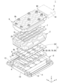
- FIG. 1 is an exploded perspective view of a cell culture device according to an embodiment.
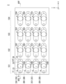
- FIG. 2 is a plan view of a chamber layer of an embodiment.
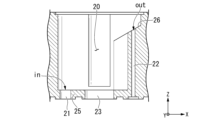
- FIG. 4 is a perspective view including the IV-IV cross section in FIG. 3; A diagram showing a part of FIG. 4 viewed from the Y direction.
- FIG. 2 is a plan view of a channel plate according to an embodiment.
- FIG. 2 is an explanatory diagram of the configuration of a channel plate according to an embodiment.
- 7(A) is a plan view of the filter layer
- FIG. 7(B) is a plan view of the first channel layer
- FIG. 7(C) is a plan view of the second channel layer
- FIG. 7(D) is a plan view of the porous layer.
- FIG. 7(E) is a plan view of the membrane layer
- FIG. 7(E) is a plan view of the third channel layer
- FIG. 7(F) is a plan view of the fourth channel layer.
- FIG. 2 is an explanatory diagram of a configuration of a filter layer according to an embodiment.
- FIG. 8(A) is a first diagram in which a part of the filter layer is enlarged
- FIG. 8(B) is a second diagram in which a part of the filter layer is enlarged.
- the 1st figure showing an example of a gas inflow prevention part of an embodiment.
- the 2nd figure showing an example of a gas inflow prevention part of an embodiment.
- FIG. 3 is a plan view showing an example of a track etched film.
- FIG. 1 is a perspective view showing an example of a honeycomb film.
- the first diagram showing an example of a filter layer.
- the 2nd figure showing an example of a filter layer.
- the third diagram showing an example of a filter layer.
- Graph showing the flow rate measurement results of a cell culture device of a comparative example Graph showing the flow rate measurement results of the cell culture device of Example.
- Fluorescent image of PD-MPS cells Fluorescent image of cells in a 6-well plate.
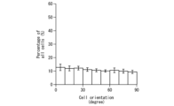
- Graph showing analysis results of cell orientation in PD-MPS Graph showing analysis results of cell orientation in a 6-well plate.
- an XYZ coordinate system is shown as necessary.
- each direction will be defined and explained along the XYZ coordinate system as necessary.
- the X direction is an example of a first direction, and is a direction along a horizontal plane.
- the Y direction is an example of a second direction orthogonal to the first direction in the horizontal plane.
- the Z direction is an example of a third direction perpendicular to each of the first direction and the second direction, and is a direction along the vertical direction.
- the +Z direction corresponds to the upper side in the vertical direction.
- characteristic portions of the present invention may be shown enlarged in order to make the characteristics of the present invention easier to understand.
- the dimensional ratio of each component is not necessarily the same as in reality.
- FIG. 1 is an exploded perspective view of a cell culture device 1 according to an embodiment.
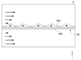
- FIG. 2 is a schematic diagram of the cell culture section 4 of the embodiment.
- the cell culture device 1 includes a chamber layer 2 (an example of a storage section), a channel plate 3 (an example of a channel forming section), a pressure adjustment device 5 (an example of a circulating flow control section), a rubber sheet 7, a holder 8, and A lid 9 is provided.
- the channel plate 3 includes channel layers 40, 50, 70, and 80 (an example of at least one channel forming body) having a cell culture section 4, and a filter layer 30 (an example of a filter section).
- the cell culture device 1 is configured by stacking a channel plate 3, a chamber layer 2, a rubber sheet 7, and a lid 9 in this order on a holder 8.
- the holder 8 fixes the channel plate 3, the chamber layer 2, the rubber sheet 7, and the lid 9.
- the holder 8 includes a box-shaped storage member 10 that can store the channel plate 3, etc., and a first fastener 11 (an example of a pressing member) for pressing the lid 9, etc. toward the storage member 10. and a second fastener 12 (an example of a pressing member) for pressing the chamber layer 2 and the like toward the storage member 10.
- the first fastener 11 and the second fastener 12 are attached to the storage member 10 so as to be rotatable around an axis along the X direction.
- a pair of first fasteners 11 and a pair of second fasteners 12 are provided. Note that the configuration of the holder 8 and the number of fasteners installed are not limited to those described above, and can be changed according to required specifications.
- the holder 8 of the cell culture device 1 of the embodiment can be manufactured by cutting aluminum.
- FIG. 3 is a plan view of the chamber layer 2 of the embodiment.
- FIG. 4 is a perspective view including the IV-IV cross section in FIG. 3.
- FIG. 5 is a diagram of a part of FIG. 4 viewed from the Y direction.
- the chamber layer 2 functions as a storage section having a first space and a second space in which a liquid medium can be stored.
- the chamber layer 2 has a storage space 20 that can store a culture solution (liquid).
- the storage space 20 has an oval outer shape in plan view (when viewed from the +Z direction side).
- the chamber layer 2 includes a plurality of culture medium chambers 20A1-20A4, 20B1-20B4, 20C1-20C4, and 20D1-20D4.
- the culture solution chamber has a long side in a first direction (X direction) and a short side in a second direction (Y direction) in plan view.
- the chamber layer 2 of the embodiment can be produced by cutting polycarbonate.
- the row direction (an example of the first direction) is a direction along the length of the culture solution chamber in plan view.
- the column direction is a direction along the short side of the culture solution chamber (direction perpendicular to the length of the culture solution chamber in plan view) in plan view. Note that the plan view shape and number of culture solution chambers installed are not limited to those described above, and can be changed according to required specifications.
- the cell culture device 1 of the embodiment includes four culture units 101, 102, 103, and 104 arranged in the X direction.
- the four culture units 101, 102, 103, 104 lined up in the It is also referred to as "culture unit 104".
- four culture solution chambers 20A1 (20A2-20A4), 20B1 (20B2-20B4), 20C1 (20C2-20C4), and 20D1 (20D2-20D4) that constitute one culture unit and are lined up in the Y direction are sequentially arranged from the +Y side. Also referred to as "first chamber 2A,” “second chamber 2B,” “third chamber 2C,” and “fourth chamber 2D.” Note that the configuration mode, number of installed culture units, etc. are not limited to those described above, and can be changed according to required specifications.
- the culture solution chamber includes a storage space 20 that can store a liquid medium (liquid), a first communication path 21 and a second communication path 22 that communicate with the storage space 20, and a first communication path 21 and a second communication path 22. It has a window hole 23 (hereinafter also referred to as "chamber window hole 23") located between.
- the culture solution chamber includes a bottom 25 located on the -Z side of the storage space 20, and a protrusion 26 that protrudes from the bottom 25 in the +Z direction.
- the raised portion 26 is provided on the +X side of the storage space 20.
- the top surface of the raised portion 26 is located at a higher position than the top surface of the bottom portion 25.
- the upper surface of the raised portion 26 is gradually inclined toward the ⁇ X side so as to be located on the ⁇ Z side.
- the first communication path 21 penetrates the bottom 25 of the culture medium chamber in the Z direction.
- the second communication path 22 passes through the raised portion 26 in the Z direction.
- the upper end of the second communication path 22 is located at a higher position than the upper end of the first communication path 21.
- the chamber window hole 23 penetrates the center side of the bottom portion 25 in the X direction in the Z direction.
- the chamber window hole 23 has a circular shape that is larger than the first communication path 21 in plan view.
- each of the first chamber 2A, second chamber 2B, third chamber 2C, and fourth chamber 2D has a culture solution inlet (in in the figure) at the ⁇ X side of the chamber window hole 23.
- a culture solution outlet (out in the figure) is provided on the +X side of the chamber window hole 23.
- the upper end of the first communication path 21 corresponds to the culture solution inlet (in in the figure)
- the upper end of the second communication path 22 corresponds to the culture solution outlet (out in the figure).
- FIG. 6 is a plan view of the channel plate 3 of the embodiment.
- FIG. 7 is an explanatory diagram of the configuration of the channel plate 3 of the embodiment.
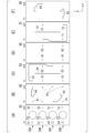
- 7(A) is a plan view of the filter layer 30
- FIG. 7(B) is a plan view of the first channel layer 40
- FIG. 7(C) is a plan view of the second channel layer 50
- FIG. 7(D) is a plan view of the filter layer 30.
- 7(E) shows a plan view of the porous membrane layer 60
- FIG. 7(E) shows a plan view of the third channel layer 70
- FIG. 7(F) shows a plan view of the fourth channel layer 80.
- the channel plate 3 functions as a channel forming section having a first channel and a second channel that communicate the first space and the second space with each other.
- the channel plate 3 is composed of a filter layer 30, a porous membrane layer 60, and a plurality of channel layers 40, 50, 70, and 80.
- the channel plate 3 of the embodiment can be produced by laminating the filter layer 30, the porous membrane layer 60, and a plurality of channel layers 40, 50, 70, and 80 and joining them with an adhesive or the like. can.
- FIG. 8 is an explanatory diagram of the configuration of the filter layer 30 of the embodiment.
- FIG. 8(A) shows a first diagram in which a part of the filter layer 30 is enlarged
- FIG. 8(B) shows a second diagram in which a part of the filter layer 30 is enlarged.
- 8(A) shows a portion of the filter layer 30 that overlaps with the first chamber 2A or the second chamber 2B in a plan view
- FIG. 8(B) shows a portion of the filter layer 30 that overlaps with the third chamber 2C or the fourth chamber 2D in a plan view. corresponds to a portion.
- FIG. 9 is a first diagram showing an example of the gas inflow prevention section 6 of the embodiment.
- FIG. 10 is a second diagram showing an example of the gas inflow prevention section 6 of the embodiment.
- first filter 30A the part of the filter layer 30 that overlaps with the first chamber 2A in plan view
- second filter 30B the part that overlaps with the third chamber 2C in plan view
- third filter 30C the part that overlaps with the fourth chamber 2D in plan view
- fourth filter 30D the overlapping portion with the fourth chamber 2D in plan view
- the filter layer 30 is composed of a planar structure 6a (hereinafter also referred to as a planar structure), and is a region of the planar structure 6a in which at least one through hole 6h is formed to prevent gas from flowing in.
- a gas inflow prevention section 6 is provided.
- the gas inflow prevention part 6 itself and the filter part (filter layer, etc.) are also treated as a "structure”.
- the gas inflow prevention portion 6 is provided at one or more locations in the planar direction of the planar structure 6a.
- the filter layer 30 can adopt a configuration in which gas inflow prevention portions 6 are provided at one or more locations in the surface direction of the filter layer 30 .
- 9 and 10 show an example of a filter layer 30 having a gas inflow prevention portion 6, which is a region in which a plurality of through holes 6h are collectively formed in a part of the planar structure 6a in the planar direction.
- 9 and 10 show an example of the gas inflow prevention portion 6, which is a region in which three or more through holes 6h are collectively formed in a part of the planar structure 6a in the planar direction.
- the gas inflow prevention portion 6, which is a region where three or more through holes 6h are collectively formed, includes three or more through holes 6h forming the outermost periphery of the gas inflow prevention portion 6.
- the filter layer 30 includes a first gas inflow prevention section 31 (gas inflow prevention section 6, see FIG.
- the filter layer 30 has a plurality of through holes 31h (through holes 6h), and a plurality of through holes. 32h (through hole 6h).
- the number of through holes 31h that the first gas inflow prevention section 31 has is greater than the number of through holes 32h that the second gas inflow prevention section 32 has.
- the through holes 31h and 32h that each gas inflow prevention part 31 and 32 have are circular in plan view. Note that the configuration of the filter layer 30 is not limited to the above, and can be changed according to required specifications.
- the diameter of the through hole 6h of the gas inflow prevention part 6 is 0.005 mm or more and 0.2 mm or less.
- the first gas inflow prevention section 31 includes a first filter 30A and a second filter that overlap in plan view with the ins of the first chamber 2A and second chamber 2B, as shown in FIGS. 8(A) and 8(B). They are formed at a position corresponding to the in of the filter 30B, and at a position corresponding to the out of the third filter 30C and the fourth filter 30D, which overlap in plan view with the out of the third chamber 2C and the fourth chamber 2D. As shown in FIG.
- the first gas inflow prevention portion 31 of the illustrated embodiment has 91 through holes 31h each having a diameter of 40 ⁇ m and a length of 50 ⁇ m (corresponding to the filter membrane thickness).
- the three or more (91 in FIG. 9) through holes 31h of the first gas inflow prevention part 31 illustrated in FIG. 9, 30 located at the outermost periphery of the first gas inflow prevention part 31 have a regular hexagonal shape in plan view. It is located on a line segment that forms .
- the first gas inflow prevention portion 31 has a regular hexagonal shape in a plan view surrounding the outside of the array of through holes 31h that constitutes the outermost periphery in the planar direction of the planar structure 6a along the array of through holes 31h that constitutes the outermost periphery.
- the diameter of the through hole of the gas inflow prevention part 6 can be designed in consideration of the pressure resistance of the gas inflow prevention part and the surface tension of the liquid medium.
- PB is the expected pressure resistance [Pa] of the gas inflow prevention part 6
- ⁇ is the surface tension between the liquid culture medium and air [N/m]
- D P is the expected pressure resistance of the gas inflow prevention part 6.
- the diameter of the gas inflow prevention part can be designed to be 0.2 mm in order to make the withstand pressure 1 kPa.
- the gas inflow prevention part 6 can perform the function of preventing gas inflow in a single through hole 6h, but in order to avoid clogging with dust etc. when the liquid culture medium passes through, a plurality of through holes 6h are required. A form having the following is preferable. Furthermore, in the case where the gas inflow prevention part 6 has a plurality of through holes 6h, if the diameter and length of the plurality of through holes 6h in the gas inflow prevention part 6 are uniform, it is easy to estimate the pressure resistance and the flow rate of the liquid culture medium. become.
- the diameters and lengths of the plurality of through holes 6h do not necessarily need to be uniform in order to achieve the function of the gas inflow prevention part 6 of "preventing gas inflow while allowing the liquid medium to pass through”.
- the pressure resistance of the gas inflow prevention part 6 is determined by the through hole 6h having the largest diameter among the plurality of through holes. Ru.
- the second gas inflow prevention unit 32 of the illustrated embodiment includes a first filter 30A and a first filter 30A that overlap the outs of the first chamber 2A and the second chamber 2B in plan view, as shown in FIGS. 8(A) and 8(B). It is formed at a position corresponding to the out of the second filter 30B.
- the second gas inflow prevention part 32 illustrated in FIG. 10 has 16 through holes 32h each having a diameter of 40 ⁇ m and a length of 50 ⁇ m (corresponding to the filter membrane thickness). Further, the second gas inflow prevention portion 32 illustrated in FIG. 10 is arranged in a generally rectangular shape in plan view with twelve through holes 32h located at the outermost periphery.
- the second gas inflow prevention portion 32 has a rectangular outer periphery in plan view that surrounds the outside of the array of through holes 32h that constitutes the outermost periphery in the planar direction of the planar structure 6a along the array of through holes 32h that constitutes the outermost periphery. It is an area having a shape. In the plurality of through holes 31h and 32h that each gas inflow prevention section 31 and 32 has, the distance between two adjacent through holes is set to the same size. Note that the size and number of through-holes, the external shape of the plurality of through-holes in plan view, etc. are not limited to those described above, and can be changed according to required specifications.
- the filter layer 30 has a circular through hole 33 (hereinafter also referred to as "filter window hole 33”) in a plan view at a position corresponding to the chamber window hole 23.
- filter window hole 33 a circular through hole 33 in a plan view at a position corresponding to the chamber window hole 23.
- the filter layer 30 has filter window holes 33 in the positions corresponding to the ins of the third filter 30C and the fourth filter 30D, which overlap in the plan view with the ins of the third chamber 2C and the fourth chamber 2D.
- It has a circular through hole 34 (hereinafter also referred to as "filter in side hole 34”) smaller than the filter.
- the filter in side hole 34 communicates with the passage and through-hole of the channel layer 40 as a connection hole for the culture solution to the channel layer.
- the arrangement mode, plan view shape, etc. of the filter window hole 33 and the filter in side hole 34 are not limited to those described above, and can be changed according to the required specifications.
- the first gas inflow prevention part 31, the filter window hole 33, and the second gas inflow prevention part 32 are spaced in the X direction in the order of -X side in plan view. They are lined up with a gap between them.
- the filter in side hole 34, the filter window hole 33, and the first gas inflow prevention part 31 are arranged at intervals in the X direction in this order from the ⁇ X side in plan view.
- the filter layer 30 may be made of a photosensitive photoresist.
- at least a portion of the gas inflow prevention section 6 may be made of a photosensitive photoresist.
- the filter layer 30 may be composed of a support material layer made of acrylic, PET, polystyrene, polypropylene, polyethylene, cycloolefin, etc., and a photoresist layer having the gas inflow prevention part 6.
- at least one through hole included in each of the inflow prevention parts 31 and 32 may be formed within the plane of the photoresist layer.
- the cell culture device 1 has a plurality of gas inflow prevention parts 6, at least a part of the plurality of gas inflow prevention parts 6 may be constituted by a through hole provided in a photosensitive photoresist layer. good.
- the filter layer 30 can be manufactured by a photolithography process using a light-sensitive photoresist.
- the photoresist can be used after being coated on the PET film and processed through common photolithography processes such as baking, exposure, and development. Baking, exposure, and development can be performed according to recommended processing conditions for commercially available photoresists.
- the resist film can be bonded to the channel layer, and the PET film can be peeled off for use.
- the planar structure 6a constituting the filter layer 30 may be composed of a porous membrane or a membrane having through holes.
- the track-etched film 130 manufactured by irradiating a thin film of polycarbonate and polyester with heavy ions and then performing an etching process is preferable because it is a film having through-holes with uniform diameters.
- FIG. 11 is a plan view showing an example of the track etched film 130.
- a track-etched film made of polyimide, polycarbonate, or polyester may be used.
- the filter layer may be comprised of the track-etched film 130.
- the gas inflow prevention section 6 may be configured by the track etched film 130, and the through hole 6h of the gas inflow prevention section 6 may be configured by a through hole included in the track etched film 130.
- the filter layer 30 can be manufactured by cutting the track-etched film 130 into appropriate outer dimensions.
- the filter layer 30 may be composed of a support material layer made of acrylic, PET, polystyrene, polypropylene, polyethylene, cycloolefin, etc., and a track-etched film 130 having the gas inflow prevention portion 6.
- the filter layer 30 can be manufactured by bonding the support material layer and the track-etched film 130 using heat fusion or adhesive.
- the cell culture device 1 has a plurality of filter layers 30, at least a part of the through holes 6h of the gas inflow prevention part 6 of the plurality of filter layers 30 are formed by the through holes of the track etched film 130. Good too.
- the track etched film 130 is a film having a minimum pore diameter (absolute pore diameter) of 10 nm or more.
- the track-etched film 130 has a narrower pore size distribution and is thinner than a depth filter which is a general membrane material. Note that the configuration of the track etched film 130 is not limited to the above, and can be changed according to required specifications.
- a honeycomb film can be used as a membrane having through holes. Like the track-etched film, the honeycomb film is also preferable because it has through-holes with uniform diameters.
- FIG. 12 is a perspective view showing an example of the honeycomb film 230.
- a honeycomb film made of polylactic acid or poly ⁇ -caprolactone may be used as described in JP-A-2011-202100.
- the filter layer may be constituted by a honeycomb film 230.
- the gas inflow prevention section 6 may be configured by the honeycomb film 230, and the through hole 6h of the gas inflow prevention section 6 may be configured by a through hole included in the honeycomb film 230.
- the filter layer 30 can be manufactured by cutting the honeycomb film 230 into appropriate outer dimensions.
- the filter layer 30 may be constituted by a honeycomb film 230 having a support material layer made of acrylic, PET, polystyrene, polypropylene, polyethylene, cycloolefin, etc., and a gas inflow prevention portion 6 .
- the filter layer 30 can be manufactured by bonding the support material layer and the honeycomb film 230 using heat fusion or adhesive.
- the cell culture device 1 has a plurality of filter layers 30, at least a part of the through holes 6h of the gas inflow prevention part 6 of the plurality of filter layers 30 may be formed by the through holes of the honeycomb film 230. good.
- the honeycomb film 230 is a structure having fine pores arranged in a honeycomb shape on its surface.
- the honeycomb film 230 has a pore diameter of 5 ⁇ m or more and 20 ⁇ m or less, and a film thickness of 5 ⁇ m or more and 10 ⁇ m or less. Note that the configuration of the honeycomb film 230 is not limited to the above, and can be changed according to required specifications.
- FIG. 13 is a first diagram showing an example of the filter layer 330 (filter section).
- the filter layer 330 may be arranged between the chamber layer 302 and the channel layer 340 (an example of at least one channel forming body).
- the chamber layer 302 has a first space 320A and a second space 320B that can store a liquid medium.
- the channel layer 340 includes a channel 341 that communicates the first space 320A and the second space 320B with each other (in the illustrated example, only one of the first channel and the second channel is shown). has.
- the filter layer 330 is constituted by a planar structure 330a (planar structure), and is a region of the planar structure 330a that has at least one through hole 330h, which allows gas to flow in in the circulating flow.
- a gas inflow prevention section 331 is provided to prevent gas inflow.
- the gas inflow prevention part 331 is provided at the end of the flow path 341 (the end of the first flow path or the end of the second flow path).
- the gas inflow prevention portion 331 is located at a portion of the filter layer 330 that faces one end of the flow path 341 (one end of the first flow path or one end of the second flow path). provided.
- the gas inflow prevention portion 331 is located at a portion of the filter layer 330 that faces the other end of the flow path 341 (the other end of the first flow path or the other end of the second flow path). cannot be established.
- a through hole 330h is provided in a portion of the filter layer 330 facing the other end of the flow path 341 (the other end of the first flow path or the other end of the second flow path). It will be done.
- the gas inflow prevention portion 331 in a portion facing one end of the channel 341 and not providing it in a portion facing the other end, cells can be introduced into the channel.
- the gas inflow prevention part 331 is provided only in one side of the flow path 341, when generating the circulation flow described later, the liquid culture medium is introduced into the flow path from the end where the gas inflow prevention part 331 is not provided.
- a second gas inflow prevention portion 32 of the first filter 30A is provided at the other end of the flow path.
- the first communication path 21 from the culture solution inlet in of the fourth chamber 2D, the first communication path 21, the filter in side hole 34 of the fourth filter 30D, and the first in side hole of the first channel layer 40.
- FIG. 14 is a second diagram showing an example of the filter layer 330.
- the same components as in FIG. 13 are denoted by the same reference numerals, and detailed description thereof will be omitted.
- the gas inflow prevention section 331 is provided at the end of the flow path 341 (the end of the first flow path or the end of the second flow path).
- the gas inflow prevention section 331 is located at a portion of the filter layer 330 facing both ends of the flow path 341 (both ends of the first flow path or both ends of the second flow path). provided.
- the first gas inflow prevention section 31 of the first filter 30A and the first gas inflow prevention section 31 of the third filter 30C are provided at both ends of the flow path. It is provided. Similarly, for example, in FIGS.
- liquid culture medium can be transferred from either end of the flow path to the flow path. Even when the liquid is sent toward the flow, gas can be prevented from flowing into the flow path 341.
- the gas inflow prevention section 331 is provided at a portion facing both ends of the channel 341, it is difficult to introduce cells into the channel.
- FIG. 15 is a third diagram showing an example of the filter layer 530 (filter section).
- the same components as in FIG. 14 are denoted by the same reference numerals, and detailed description thereof will be omitted.
- the gas inflow prevention portion 531 is located at a portion of the filter layer 530 facing both ends of the flow path 341 (both ends of the first flow path or both ends of the second flow path). provided.
- the channel layer 340 has a recess 342 into which the filter layer 530 can be attached.
- filter layer 530 is removably attached to recess 342 of channel layer 340 .
- the filter layer 530 may have a disc-like shape in plan view.
- the gas inflow prevention part 531 may not be provided in the filter layer 530, and the gas inflow prevention part 531 itself may be detachably attached to the recess 342 of the channel layer 340.
- the configuration of the filter layer 530 is not limited to the above, and can be changed according to required specifications.
- FIG. 3 is a plan view of the fourth channel layer 80 from FIG.
- the plurality of channel layers 40, 50, 70, and 80 include a first channel layer 40, a second channel layer 50, a third channel layer 70, and a fourth channel layer 80.
- each channel layer is produced by forming holes, grooves, etc. in a base material such as a PET film by laser processing or the like.
- the thickness of the PET film is 0.1 mm or more and 1 mm or less.
- the thickness of the first channel layer 40, the second channel layer 50, the third channel layer 70, and the fourth channel layer 80 may be different, but if they are the same, the flow rate of the liquid medium in each channel It becomes easy to estimate.
- the material, installation mode, and formation mode of the channel layer are not limited to those described above, and can be changed according to required specifications.
- the channel layer may be made by injection molding of polystyrene or cycloolefin resin.
- the first channel layer 40 corresponds to a part of the culture solution inlet (in in the figure) of each chamber (in of the third filter 30C, which overlaps with the culture solution inlet of the third chamber 2C in plan view).
- the three through holes 41 (hereinafter also referred to as “first in side holes 41") lead to the three through holes 41 (hereinafter also referred to as “first in side holes 41"), and a part of the culture solution outlet (out in the figure) of each chamber (first chamber 2A in plan view).
- first out side holes 42 There are three through holes 42 (hereinafter also referred to as “first out side holes 42") that communicate with the third chamber 2C (excluding the part corresponding to the out side of the first filter 30A which overlaps with the culture solution outlet) and the third chamber 2C in plan view.
- a first in-side passage 43 connected to the filter in-side hole 34 of the third filter 30C, which overlaps with the culture solution inlet (in in the figure), and a first in-side passage 43 that overlaps with the culture solution outlet (out in the figure) of the first chamber 2A in plan view. It has a first out side passage 44 connected to the second gas inflow prevention part 32 of the filter 30A.
- the first in-side passage 43 curves toward the +X side and the ⁇ Y side from a region that overlaps with the filter in-side hole 34 of the third filter 30C in a plan view toward a region that overlaps with the center of the filter window hole 33 in the X direction in a plan view. After that, it extends to the +Y side.
- the first out side passage 44 extends toward the ⁇ X side from a portion of the first filter 30A that overlaps with the second gas inflow prevention portion 32 in a plan view, and then extends from a portion that overlaps with the center of the filter window hole 33 in the X direction in a plan view. It extends while curving towards the -Y side. Note that the installation manner of the through holes and passages (flow paths) that the first flow path layer 40 has is not limited to the above, and can be changed according to the required specifications.
- the second channel layer 50 includes a part of the culture solution inlet (in in the figure) of each chamber (a portion of the culture solution inlet of the four chambers, which overlaps with the culture solution inlet of the second chamber 2B and fourth chamber 2D in plan view).
- There are two through holes 51 (hereinafter also referred to as “second in side holes 51") communicating with the second in side filter 30B and the fourth filter 30D (the two parts corresponding to the in side), and the culture solution outlet of each chamber (out in the figure).
- the first channel layer 40 corresponds to the hole 52 (hereinafter also referred to as "second out hole 52") and the in of the first filter 30A, which overlaps the culture solution inlet (in in the figure) of the first chamber 2A in plan view. and the first out side hole 42 of the first channel layer 40 corresponding to the out of the third filter 30C, which overlaps with the culture solution outlet (out in the figure) of the third chamber 2C in plan view. It also has a second in-out communication path 53 located above the porous membrane layer 60, and a second vertical communication path 54 communicating with the upper and lower sides of the porous membrane layer 60.
- the second in-out communication passage 53 extends toward the +X side from a portion that overlaps with the first in-side hole 41 of the first flow path layer 40 corresponding to the in of the first filter 30A in a plan view, and then extends toward the +X side. It extends in the ⁇ Y side toward a portion overlapping with the first out side hole 42 of the first channel layer 40 corresponding to the out of the third filter 30C.
- the second vertical communication passage 54 is arranged in the X direction of the second passage layer 50 so as to connect the +X end of the first in side passage 43 and the -Y end of the first out side passage 44 of the first passage layer 40 in plan view. It extends in the center along the Y direction. Note that the installation manner of the through holes and passages (flow paths) that the second flow path layer 50 has is not limited to the above, and can be changed according to the required specifications.
- the porous membrane layer 60 is a part of the culture solution inlet (in in the figure) of each chamber (second chamber 2B in plan view of the four chambers). and two through holes 61 (hereinafter also referred to as "in side holes 61") communicating with the second filter 30B and the part corresponding to the in of the fourth filter 30D, which overlap with the culture solution inlet of the fourth chamber 2D.
- a part of the culture solution outlet (out in the figure) of each chamber corresponds to the out of the second filter 30B and fourth filter 30D that overlap with the culture solution outlet of the second chamber 2B and fourth chamber 2D in plan view among the four
- It has two through-holes 62 (hereinafter also referred to as "out-side holes 62") that communicate with the two parts.
- the manner in which the through holes (channels) of the porous membrane layer 60 are provided is not limited to the above, and can be changed according to the required specifications.
- the third channel layer 70 includes a part of the culture solution inlet (in in the figure) of each chamber (in of the fourth filter 30D that overlaps with the culture solution inlet of the fourth chamber 2D in plan view).
- the through hole 71 (hereinafter also referred to as the "third in side hole 71") leads to a part (one of the parts corresponding to The through hole 72 (hereinafter also referred to as "third out side hole 72") that communicates with the second chamber 2B (one of the parts corresponding to the out side of the second filter 30B that overlaps with the culture solution outlet of the second chamber 2B) and the second chamber 2B in plan view.
- the third in-out communication path 73 extends toward the ⁇ Y side from a portion that overlaps with the in-side hole 61 of the porous membrane layer 60 corresponding to the in of the second filter 30B in a plan view, and then extends from the fourth in-out communication path in a plan view. It extends toward the +X side toward a portion overlapping with the out side hole 62 of the porous membrane layer 60 corresponding to the out of the filter 30D.
- the third vertical communication passage 74 is a portion that overlaps with the second vertical communication passage 54 of the second passage layer 50 in plan view, and extends along the Y direction from the center of the third passage layer 70 in the X direction. Note that the manner in which the through holes and passages (flow paths) of the third flow path layer 70 are installed is not limited to the above, and can be changed according to the required specifications.
- the fourth flow path layer 80 has a third in side hole 71 of the third flow path layer 70 that corresponds to the in of the fourth filter 30D that overlaps with the culture solution inlet of the fourth chamber 2D in plan view.
- the fourth in side passage 83 extends toward the ⁇ X side from a portion overlapping with the third in side hole 71 of the third flow path layer 70 corresponding to the in of the fourth filter 30D in a plan view, and then extends toward the ⁇ X side. It extends while curving toward the +Y side toward a portion of the flow path layer 70 that overlaps with the -Y end of the third vertical communication passage 74.
- the fourth out side passage 84 is the third upper and lower communication passage of the third flow path layer 70 when viewed from a portion overlapping with the third out side hole 72 of the third flow path layer 70 corresponding to the out of the second filter 30B when viewed from above.
- the fourth channel layer 80 It extends while being curved towards the -X side and the +Y side toward a portion overlapping with the +Y end of 74, and then extends to the -Y side. Note that the manner in which the through holes and passages (channels) of the fourth channel layer 80 are arranged is not limited to the above, and can be changed according to the required specifications.
- the porous membrane layer 60 is provided between the second channel layer 50 and the third channel layer 70.
- the cell culture section 4 is provided on the porous membrane layer 60 between the second vertical communication path 54 of the second channel layer 50 and the third vertical communication path 74 of the third channel layer 70. .
- Cells are cultured in this cell culture section 4.
- the cell culture section 4 is an example of a cell culture section provided in at least a portion of the first space, the second space, the first channel, and the second channel.
- the porous membrane layer 60 separates an upper space and a lower space within the channel plate 3.
- the porous membrane layer 60 is permeable to fluid due to the pressure difference between the upper space and the lower space.
- the porous membrane layer 60 is impermeable to cells.
- the average pore diameter of the porous membrane layer 60 is 0.1 ⁇ m or more and 30 ⁇ m or less.
- the pores of the porous membrane layer 60 are large enough to allow liquid to pass through, but not to allow cells to pass through.
- the thickness of the porous membrane layer 60 is 0.1 ⁇ m or more and 100 ⁇ m or less.
- the material of the porous membrane layer 60 is polyimide, polycarbonate, polyester, silicone resin, or the like.
- the upper surface of the porous membrane layer 60 (the surface on which cells are placed) is preferably coated with a cell adhesive material.
- the cell-adhesive material includes a protein having cell-adhesive properties.
- cell adhesive materials include gelatin, collagen, fibronectin, laminin, vidronectin, matrigel, polylysine, and the like.
- the channel plate 3 of this embodiment is configured to culture cells on the porous membrane layer 60 by flowing a culture solution above and below the porous membrane layer 60.
- the channels indicated by one-dot chain lines are channels formed on the porous membrane layer 60
- the channels indicated by two-dot chain lines are channels formed below the porous membrane layer 60
- the channels indicated by solid lines are channels formed below the porous membrane layer 60.
- Channels formed on the upper and lower sides of the porous membrane layer 60 are shown, respectively.
- cells on the porous membrane layer 60 are cultured in portions along flow channels (in this embodiment, the upper and lower communication channels 54 and 74) formed above and below the porous membrane layer 60.
- the rubber sheet 7 has a rectangular outer shape in plan view.
- the rubber sheet 7 functions as a sealing member provided between the lid 9 and the chamber layer 2.
- the rubber sheet 7 is made of a softer material than the lid 9 and the chamber layer 2. Note that the configuration of the rubber sheet 7 is not limited to the above, and can be changed according to required specifications.
- the rubber sheet 7 of the embodiment can be produced by water jet processing a flat plate of a rubber sheet.
- the rubber sheet 7 has a plurality of opening holes 7h.
- the opening hole 7h has an oval shape along the storage space 20 of the culture solution chamber in plan view. Sixteen opening holes 7h are arranged in four rows and four columns, corresponding to the plurality of culture solution chambers. Note that the shape of the opening holes 7h in plan view, the number of installed holes, etc. are not limited to those described above, and can be changed according to the required specifications.
- a flexible component such as a silicone resin sheet or an O-ring may be provided instead of or together with the rubber sheet 7. Thereby, pressure leakage and liquid leakage from the gap between the lid 9 and the chamber layer 2 can be prevented.
- a sealing member such as a silicone resin sheet or an O-ring
- the manner in which the sealing member is installed is not limited to the above, and can be changed according to required specifications.
- the lid 9 has the function of freely opening and closing the opening of the chamber layer 2 (the upper opening of the storage space 20) and airtightly sealing it.
- the lid 9 has a plurality of observation windows 9h through which the inside of the culture solution chamber can be observed from the outside.
- the observation window 9h has an oval shape along the storage space 20 of the culture solution chamber in plan view.
- a plurality of 16 observation windows 9h are provided in four rows and four columns, corresponding to the plurality of culture solution chambers. Note that the shape of the observation window 9h in plan view, the number of installations, etc. are not limited to those described above, and can be changed according to required specifications.
- the lid 9 of the embodiment can be manufactured by cutting polycarbonate.
- An air filter 90 is attached to the lid 9. It is configured such that air pressure can be applied to the culture solution chamber via the air filter 90.
- four air filters 90 are provided in line in the Y direction. Note that the number of installed air filters 90, etc. is not limited to the above, and can be changed according to required specifications.
- the lid 9 is provided with a pneumatic pipe (not shown, an example of a pressurizing line) to which the air filter 90 is connected.
- the pneumatic piping communicates with a pneumatic pump 91 (an example of the configuration of the pressure adjustment device 5) via an air filter 90.
- a pneumatic pump 91 an example of the configuration of the pressure adjustment device 5
- four pneumatic pipes are provided corresponding to the air filters 90.
- the first pneumatic pipe corresponding to the one closest to +Y among the four air filters 90 communicates with the four culture solution chambers (first chamber 2A in this embodiment) closest to +Y in the chamber layer 2.
- the other three pneumatic pipes also have the same configuration as the first pneumatic pipe. Note that the configuration of the pneumatic piping is not limited to the above, and can be changed according to required specifications.
- the pressure adjustment device 5 may include a pneumatic pump 91, a regulator for adjusting the pressure, and a solenoid valve for applying and releasing the pressure according to a sequence over time.
- the pneumatic piping is configured to be able to supply air (an example of gas) to the culture solution chamber and to discharge air from the culture solution chamber.
- air an example of gas
- an air filter 90 is connected to the pneumatic piping. Therefore, the air filter 90 can prevent foreign matter from entering the culture solution chamber.
- each culture solution chamber may be configured to be able to pressurize four culture solution chambers at the same time.
- the four culture solution chambers may be configured to be pressurized in sequence.
- it may be configured such that four culture solution chambers can be opened to atmospheric pressure at the same time.
- the four culture solution chambers may be configured to be sequentially exposed to atmospheric pressure.
- the pressurization mode of each culture solution chamber is not limited to the above, and can be changed according to required specifications.
- Example of circulating flow of culture solution In the plan view of the channel plate 3 of the embodiment shown in FIG.
- the channels formed in the solid line and the channels shown in solid lines indicate the channels formed above and below the porous membrane layer 60, respectively.
- the culture solution passes above the porous membrane layer 60 along the channels included in the first channel layer 40 and the second channel layer 50 that constitute the channel plate 3, and the culture solution passes through the upper side of the porous membrane layer 60. It is configured such that the culture solution passes under the porous membrane layer 60 along the channels that the fourth channel layer 70 and the fourth channel layer 80 have.
- the culture solution can be alternately sent and returned above the porous membrane layer 60.
- the culture solution stored in the storage space 20C of the third chamber 2C is transferred to the culture solution inlet in of the third chamber 2C, the first communication path 21, and the filter of the third filter 30C.
- the liquid is fed through the second gas inflow prevention section 32, the second communication path 22 of the first chamber 2A, and the culture solution outlet out (liquid feeding channel W1A along the direction of arrow V1A in the figure).
- the upper end of the first communication path 21 on the in side is located lower than the upper end of the second communication path 22 on the out side in each chamber. Therefore, when the third chamber 2C is pressurized, the culture solution enters from the lower part of the third chamber 2C, and the culture solution comes out from the higher part of the first chamber 2A. During the process of feeding the culture solution, the air present in the storage space 20C of the third chamber 2C is prevented from flowing into the first out side hole 42 by the first gas inflow prevention part 31 of the third filter 30C.
- the gas inflow prevention part is not provided at the filter in side hole 34 of the third filter 30C, the air present in the storage space 20C of the third chamber 2C is It is preferable to stop pressurizing the third chamber 2C before flowing into the side passage 43.
- the culture solution stored in the storage space 20A of the first chamber 2A is transferred to the culture solution inlet in of the first chamber 2A, the first communication path 21, and the first filter 30A.
- 1 gas inflow prevention part 31 the first in-side hole 41 of the first flow path layer 40, the second in-out communication path 53 of the second flow path layer 50, the first out side hole 42 of the first flow path layer 40, the third It is returned through the first gas inflow prevention part 31 of the filter 30C, the second communication path 22 of the third chamber 2C, and the culture solution outlet out (return flow path W1B along the direction of arrow V1B in the figure).
- the upper end of the first communication path 21 on the in side is located lower than the upper end of the second communication path 22 on the out side in each chamber. Therefore, when the first chamber 2A is pressurized, the culture solution enters from the lower part of the first chamber 2A, and the culture solution comes out from the higher part of the third chamber 2C. During the process of returning the culture solution, the air present in the storage space 20A of the first chamber 2A is prevented from flowing into the first in-side hole 41 by the first gas inflow prevention part 31 of the first filter 30A. Further, during the process of returning the culture solution, the air present in the storage space 20A of the first chamber 2A is prevented from flowing into the first out side passage 44 by the second gas inflow prevention part 32 of the first filter 30A.
- the culture solution passing through the channel above the porous membrane layer 60 circulates and flows between the first chamber 2A and the third chamber 2C.
- one of the storage spaces 20A and 20C that the first chamber 2A and the third chamber 2C have corresponds to one of the first space and the second space that can store the liquid medium
- the other of the storage spaces 20A and 20C of the chamber 2C corresponds to the other of the first space and the second space capable of storing a liquid medium
- one of the liquid sending channel W1A and the return channel W1B corresponds to the first space and the second space.
- the other corresponds to one of the first flow path and the second flow path that communicate the spaces with each other
- the other of the liquid sending flow path W1A and the return flow path W1B corresponds to the first flow path and the second flow path that communicate the first space and the second space with each other. This corresponds to the other of the two channels.
- the circulating flow of the culture solution passing through the channel above the porous membrane layer 60 is not limited to the above, and can be changed according to the required specifications.
- the culture solution stored in the storage space 20D of the fourth chamber 2D is transferred to the culture solution inlet in of the fourth chamber 2D, the first communication path 21, and the filter of the fourth filter 30D.
- the liquid is fed through the second gas inflow prevention section 32, the second communication path 22 of the second chamber 2B, and the culture solution outlet out (liquid feeding channel W2A along the direction of arrow V2A in the figure).
- the upper end of the first communication path 21 on the in side is located lower than the upper end of the second communication path 22 on the out side in each chamber. Therefore, when the fourth chamber 2D is pressurized, the culture solution enters from the lower part of the fourth chamber 2D and comes out from the higher part of the second chamber 2B. During the process of feeding the culture solution, the air present in the storage space 20D of the fourth chamber 2D is prevented from flowing into the first out side hole 42 by the first gas inflow prevention part 31 of the fourth filter 30D.
- the culture solution stored in the storage space 20B of the second chamber 2B is transferred to the culture solution inlet in of the second chamber 2B, the first communication path 21, and the second filter 30B.
- 1 gas inflow prevention part 31 the first in-side hole 41 of the first channel layer 40, the second in-side hole 51 of the second channel layer 50, the in-side hole 61 of the porous membrane layer 60, the third channel layer 70 , the third in-out communication path 73, the out side hole 62 of the porous membrane layer 60, the second out side hole 52 of the second channel layer 50, the first out side hole 42 of the first channel layer 40, and the fourth filter 30D.
- the liquid is returned through the first gas inflow prevention part 31, the second communication path 22 of the fourth chamber 2D, and the culture solution outlet out (return flow path W2B along the direction of arrow V2B in the figure).
- the upper end of the first communication path 21 on the in side is located lower than the upper end of the second communication path 22 on the out side in each chamber. Therefore, when the second chamber 2B is pressurized, the culture solution enters from the lower part of the second chamber 2B, and the culture solution comes out from the higher part of the fourth chamber 2D. During the process of returning the culture solution, the air present in the storage space 20B of the second chamber 2B is prevented from flowing into the first in-side hole 41 by the first gas inflow prevention part 31 of the second filter 30B. Further, during the process of returning the culture solution, the air present in the storage space 20B of the second chamber 2B is prevented from flowing into the first out side hole 42 by the second gas inflow prevention part 32 of the second filter 30B.
- the culture solution passing through the flow path under the porous membrane layer 60 circulates and flows between the second chamber 2B and the fourth chamber 2D.
- one of the storage spaces 20B and 20D that the second chamber 2B and the fourth chamber 2D have corresponds to one of the first space and the second space that can store the liquid medium
- the second chamber 2B and the fourth The other of the storage spaces 20B and 20D that the chamber 2D has corresponds to the other of the first space and the second space that can store a liquid medium
- one of the liquid sending channel W2A and the return channel W2B corresponds to the first space and the second space.
- the other corresponds to one of the first flow path and the second flow path that communicate the spaces with each other
- the other of the liquid sending flow path W2A and the return flow path W2B corresponds to the first flow path and the second flow path that communicate the first space and the second space with each other. This corresponds to the other of the two channels.
- the circulation flow of the culture solution passing through the channel under the porous membrane layer 60 is not limited to the above, and can be changed according to the required specifications.
- two of the four culture solution chambers 2A1, 2B1, 2C1, and 2D1 is a microchannel in the channel plate 3 (in the illustrated example, the first filter 30A, the third filter 30C, the first channel layer 40, the second channel layer 50, etc.). are connected by a flow path).
- the first circulating flow of the culture solution in the illustrated example, the flow along the liquid sending channel W1A in the direction of the arrow V1A and the return channel W1B in the direction of the arrow V1B) can be realized.
- the four culture solution chambers 2A1, 2B1, 2C1, and 2D1 constituting one culture unit the first culture unit 101 in the example in the figure
- another two in the example in the figure, the second chamber 2B1 and the fourth A second set combining the microchannels (chamber 2D1) in the channel plate 3 (in the example shown, the second filter 30B, the fourth filter 30D, the first channel layer 40, the second channel layer 50, and the porous
- the membrane layer 60, the third flow path layer 70, the fourth flow path layer 80, etc. are connected by a flow path).
- a second circulating flow of the culture solution in the illustrated example, the liquid sending channel W2A in the direction of arrow V2A and the return channel W2B in the direction of arrow V2B
- the cell culture device 1 of this embodiment is composed of four culture units 101, 102, 103, and 104 lined up in the X direction.
- the other culture units in the illustrated example, the second culture unit 102 to the fourth culture unit 104) have the same configuration as the first culture unit 101. Therefore, the same circulation flow as in the first culture unit 101 can be realized in other culture units as well.
- a check valve is an example of a backflow prevention mechanism that restricts the flow of culture solution.
- a check valve includes a structure including a valve seat having a valve hole and a valve body. In the check valve having this structure, when the culture fluid flows in the forward direction, the valve hole is opened by the valve element separating from the valve seat, so the culture fluid passes through the valve hole and flows in the forward direction. On the other hand, when the culture solution flows in the opposite direction, the valve hole is closed by the valve body coming into contact with the valve seat, so that the flow of the culture solution in the reverse direction is blocked.
- the upper end of the first communication path 21 (an example of an in-side through hole) on the in side is located lower than the upper end of the second communication path 22 (an example of an out side through hole) on the out side.
- the upper end of the in-side through-hole may be located at the same height as the upper end of the out-side through-hole, or may be located at a location higher than the upper end of the out-side through-hole.
- the flow of the culture solution may be controlled by changing the height of the upper end of the in-side through-hole or the upper end of the out-side through-hole in each chamber.
- the manner of controlling the flow of the culture solution can be changed depending on the required specifications.
- the cell culture device 1 includes a storage section (chamber layer 2 of the embodiment) having a first space and a second space capable of storing a liquid medium, and a storage section (chamber layer 2 of the embodiment) that can store a liquid medium.
- a flow path forming part (flow path plate 3 of the embodiment) having a first flow path and a second flow path that communicate the spaces with each other, and at least the first space, the second space, the first flow path, and the second flow path.
- a cell culture section (cell culture section 4 of the embodiment) provided in a part of the cell culture section, and a culture solution that returns from the first space or the second space to the first space or the second space via the first flow path or the second flow path.
- a circulating flow control unit (pressure adjustment device 5 of the embodiment) for controlling the circulating flow, and a planar structure having at least one through hole to prevent gas from flowing into the circulating flow.
- the gas inflow prevention part 6 (the first gas inflow prevention part 31 and the second gas inflow prevention part 32 of the embodiment) is provided.
- the Laplace valve portion (the gas inflow prevention portion 6 of the embodiment) that requires high dimensional accuracy can be mass-produced in advance with high precision. Therefore, a structure for preventing gas inflow can be manufactured with high dimensional accuracy, and a structure suitable for industrialization can be realized.
- the gas inflow prevention section 6 is provided at the end of the first flow path or the end of the second flow path. According to this configuration, it is easier to install the gas inflow prevention part 6 compared to the case where the gas inflow prevention part 6 is provided in the middle part of the first flow path or the middle part of the second flow path. Therefore, it is suitable for maintaining the accuracy of the gas inflow prevention section 6 and realizing mass production of the cell culture device 1.
- the storage part (chamber layer 2 of the embodiment), the flow path forming part (the flow path plate 3 of the embodiment), and the gas inflow prevention part 6 according to the present embodiment are each formed in layers, and the flow path forming part, The gas inflow prevention section 6 and the storage section are stacked in this order. According to this configuration, the three layers of the flow path forming part, the gas inflow prevention part 6, and the storage part can be assembled by thermocompression bonding or the like. Therefore, it is suitable for maintaining the accuracy of the gas inflow prevention section 6 and realizing mass production of the cell culture device 1.
- the diameter of the through hole (through hole 31h, 32h of the embodiment) of the gas inflow prevention part 6 according to this embodiment is 0.005 mm or more and 0.2 mm or less. According to this configuration, durability can be ensured while maintaining the function of the gas inflow prevention section 6. Therefore, it is suitable for practical mass production of the gas inflow prevention section 6.
- the storage unit according to this embodiment is connected to a pneumatic pump 91 that can supply air. According to this configuration, the storage section can be pressurized by the pneumatic pump 91.
- An example of the gas inflow prevention section 6 according to the present embodiment is made of a photosensitive photoresist, and at least one through hole of the gas inflow prevention section 6 is formed in the photoresist. According to this configuration, the through holes of the gas inflow prevention section 6 can be arranged at desired intervals using the photoresist. Therefore, it is suitable for maintaining the accuracy of the gas inflow prevention section 6 and realizing mass production of the cell culture device 1.
- An example of the gas inflow prevention section 6 according to the present embodiment is composed of a track-etched film 130 made of polyimide, polycarbonate, or polyester.
- the track-etched film 130 has a narrower pore size distribution and is thinner than a depth filter which is a general membrane material. Therefore, it is suitable for maintaining the accuracy of the gas inflow prevention section 6 and realizing mass production of the cell culture device 1.
- An example of the gas inflow prevention section 6 according to this embodiment is configured with a honeycomb film 230.
- the honeycomb film 230 is a structure having fine pores arranged in a honeycomb shape on its surface. Therefore, it is suitable for maintaining the accuracy of the gas inflow prevention section 6 and realizing mass production of the cell culture device 1.
- the cell culture section 4 is constituted by a porous membrane layer 60 having a first surface 60a for culturing cells and a second surface 60b opposite to the first surface 60a.
- the channel forming section includes a first channel layer 40 and a second channel layer 50 arranged on the first surface 60a side of the porous membrane layer 60, and a channel forming section on the second surface 60b side of the porous membrane layer 60.
- a third channel layer 70 and a fourth channel layer 80 are arranged.
- the first channel layer 40 and the second channel layer 50 are connected to the first channel layer 40 and the second channel layer 50 from the first space or the second space through the first channel or the second channel on the first surface 60a side of the porous membrane layer 60.
- the third channel layer 70 and the fourth channel layer 80 are arranged on the second surface 60b side of the porous membrane layer 60 from the first space or the second space through the first channel or the second channel. It includes a flow path forming a circulating flow of the culture medium back to the space or the second space. According to this configuration, a circulating flow of the culture solution can be formed on both sides of the first surface 60a and the second surface 60b of the porous membrane layer 60.
- the manufacturing method of the cell culture device 1 includes a storage section having a first space and a second space capable of storing a liquid medium, a first flow path and a second space that communicate the first space and the second space with each other.
- a flow path forming section having two flow paths;
- a cell culture section provided in at least a part of the first space, the second space, the first flow path and the second flow path;
- a circulating flow control section for controlling the circulating flow of the culture solution returning to the first space or the second space via the channel or the second channel, and a planar structure having at least one through hole.
- the storage part, the channel forming part, and the gas inflow prevention part 6 are each formed in layers,
- the flow path forming part, the gas inflow prevention part 6, and the storage part are stacked and joined in this order. According to this method, the three layers of the flow path forming part, the gas inflow prevention part 6, and the storage part can be assembled by thermocompression bonding or the like. Therefore, it is suitable for maintaining the accuracy of the gas inflow prevention section 6 and realizing mass production of the cell culture device 1.
- the gas inflow prevention section is provided at the end of the first flow path or the end of the second flow path, but the present invention is not limited thereto.
- the gas inflow prevention part may be provided in the middle part of the first flow path or the middle part of the second flow path.
- a gas inflow prevention section may be provided at the intersection.
- the manner in which the gas inflow prevention section is installed can be changed depending on the required specifications.
- the storage section, the flow path forming section, and the gas inflow prevention section are each formed in layers, and an example is given in which the flow path formation section, the gas inflow prevention section, and the storage section are stacked in this order.
- the storage section, the flow path forming section, and the gas inflow prevention section may each be formed in a block shape.
- the cell culture device is not limited to a structure having a storage section, a flow path forming section, and a gas inflow prevention section separately, but may have a structure in which a storage section, a flow path formation section, and a gas inflow prevention section are integrated. It's okay.
- the diameter of the through hole of the gas inflow prevention part is described by giving an example of 0.005 mm or more and 0.2 mm or less, but the diameter is not limited to this.
- the diameter of the through hole of the gas inflow prevention part may be less than 0.005 mm or more than 0.2 mm.
- the diameter of the through hole of the gas inflow prevention part can be changed according to required specifications.
- the storage section is described as being connected to a pneumatic pump that can supply air, but the storage section is not limited to this.
- the structure for adjusting the pressure in the storage space (first space or second space) in the cell culture device is not particularly limited.
- a structure may be used in which the pressure in the storage space is increased by supplying the culture solution, or a structure in which the pressure in the storage space is reduced by discharging the culture solution.
- a structure may be used in which the pressure in the storage space is changed by changing the volume of the storage space.
- the aspect of the structure for adjusting the pressure in the storage space can be changed depending on the required specifications.
- the cell culture section is a porous membrane layer having a first surface for culturing cells and a second surface opposite to the first surface.
- the cell culture section may be a porous layer having a first surface for culturing cells and a second surface opposite to the first surface.
- the cell culture section may have a single membrane structure or a layered structure in which multiple membranes are stacked.
- the configuration of the cell culture section can be changed according to required specifications.
- the cell culture section may be provided in at least a portion of the first space, the second space, the first channel, and the second channel.
- the channel forming section includes a first channel layer and a second channel layer arranged on the first surface side of the porous membrane layer, and a channel forming section arranged on the second surface side of the porous membrane layer.
- the channel forming portion may have a single layer structure or may include five or more channel layers.
- the channel forming section may be arranged only on the first surface side of the porous membrane layer, or may be arranged only on the second surface side of the porous membrane layer.
- the configuration of the flow path forming section can be changed depending on required specifications.
- the cells to be cultured in this embodiment are not particularly limited, and for example, cells derived from animals including humans, cells derived from plants, cells derived from microorganisms, etc. can be used depending on the purpose.
- This embodiment is useful in the field of cell engineering, regenerative medicine, bio-related industry, tissue engineering, and the like. It is particularly useful for drug development and basic research in cell biology.
- FIG. 16 is a graph showing the flow rate measurement results of the cell culture device of the comparative example.
- FIG. 16 shows the variation in flow rate of the cell culture device of the comparative example.
- the vertical axis of the comparative example in FIG. 16 indicates the flow rate when pressurized at 3.9 kPa.
- FIG. 17 is a graph showing the flow rate measurement results of the cell culture device of the example.
- FIG. 17 shows the variation in flow rate of the cell culture device of the example.
- the vertical axis of the example in FIG. 17 indicates the flow rate when pressurized at 5 kPa.
- Non-Patent Document 1 Japanese Patent Application Publication No. 2020-124884
- Non-Patent Document 2 Korean Patent Application Publication No. 2020-124884
- Non-Patent Document 2 Korean Patent Application Publication No. 2020-124884
- the cell culture device of the example is the cell culture device 1 of this embodiment.
- the flow rate of each cell culture device After adding the medium to the chamber, pressurize the chamber, measure the weight of the medium stored on the outlet side (out side) after a predetermined time from the start of pressurization, and hold it for 1 minute. It was converted into a medium flow rate per unit.
- the flow rate was measured at room temperature (25°C).
- the coefficient of variation was estimated by dividing the standard deviation of the flow rate by the average value, and was used as an index of the variation in flow rate between the comparative example and the example.
- the coefficient of variation of the flow rate of the cell culture device produced by the method of the comparative example was 0.335 in the liquid sending channel and 0.331 in the return channel.
- the coefficient of variation of the flow rate of the cell culture device produced by the method of the example was 0.045 in the liquid sending channel and 0.087 in the return channel. It was confirmed that the cell culture device of the example had smaller variations in flow rate and could control the flow rate more accurately than the comparative example.
- Example of cell culture Next, an example will be described in which cell culture was performed using the cell culture device of the example while flowing a culture solution. Sterilization and pretreatment of the cell culture device were performed according to the following procedure. The outside and inside of the channel plate was filled with 70% ethanol, and after removing the ethanol in a clean bench, it was transferred to a sterilized bag and dried under reduced pressure at room temperature. The holder, rubber sheet, chamber layer, and lid were sterilized in an autoclave (20 minutes at 120°C) and then completely dried in a dryer (60°C). All parts were assembled aseptically in a clean bench.
- Collagen coating was applied to the liquid feeding channel in the channel (above the porous membrane layer: from the first chamber to the third chamber; below the porous membrane layer: from the second chamber to the fourth chamber).
- Cell Matrix Type I-C Nita Gelatin
- the burst pressure of the Laplace valve was measured after 2 days of perfusion. Four channels from the same lot were used for the measurement. The in side of the liquid sending channel or the return channel was pressurized at 4 kPa, and all the culture medium in the chamber was delivered. After that, the pressure was increased by 0.2 kPa every 20 seconds, and the differential pressure at the time the bubble passed through the Laplace valve (the pressure difference between the first chamber and the third chamber, the pressure difference between the second chamber and the fourth chamber) The pressure difference between the inside and outside was recorded. The measurement was performed three times for each channel on one plate, the lowest burst pressure was recorded, and the average value of the four plates was calculated. The bursting pressure of the Laplace valve can be estimated using the equation (1) already mentioned.
- PB is the expected bursting pressure of the Laplace valve [Pa]
- ⁇ is the surface tension between the medium and air [N/m]
- DP is the flow path plate formed in the Laplace valve.
- the diameter of the through hole is [m].
- Non-patent document 3 Jiang, L, et al.: Rhamnolipids elicit the same cytotoxic sensitivity between cancer cell and normal cell by reducing surface tension of culture medium. Appl. Microbiol. Biotechnol., 98, 10187-10196 (2014).
- the burst pressure of the Laplace valve is estimated to be 5.5 kPa.
- HUVEC For maintenance culture of HUVEC, culture was performed under conditions of 5% CO2 and 37°C using a dish coated with collagen with cell matrix type IC. After the cells reached subconfluence, they were collected using a 0.05% trypsin-5.3 mmol/L EDTA solution and centrifuged (100 g x 3 min).
- HUVEC was adjusted to 2.0 ⁇ 10 6 cells/mL with a culture medium, and 150 ⁇ L was introduced from the upper surface of the liquid feeding channel (inside of the third chamber).
- the cell culture part had a density of 600 cells/mm 2 .
- an empty chip was inserted into the out side of the first chamber, and the extruded medium was removed.
- static culture was performed in an incubator at 37° C. and 5% CO 2 for 3 hours.
- an empty chip was inserted into the out side of the first chamber, and 150 ⁇ L of the medium was introduced from the in side of the third chamber.
- the extruded medium was removed.
- the medium storage part in the chamber was filled with the medium, and 2 ml of the medium was further added.
- the pressurization operation consisted of opening the atmospheric pressure for 5 seconds at approximately 5.0 kPa (step 1), then pressurizing the first and second chambers for 60 seconds (step 2), then opening the atmospheric pressure for 5 seconds (step 3), and then opening the third chamber for 60 seconds.
- the pressurization sequence of pressurizing the chamber and the fourth chamber (step 4) was repeated.
- ASTF0401 Engineing System
- Medium exchange was performed at the time of flow rate measurement.
- a cell culture dish (Falcon TM 6-well Clear Flat Bottom TC-treated Multiwell Cell Culture Plate) was used as a control. Collagen coating was performed according to the method recommended by the manufacturer, and the cells were similarly seeded at a density of 600 cells/mm 2 .
- Observation and orientation test were performed according to the following procedure. LiveDead staining of cells on MPS or Cell culture dishes was performed on the second day after the start of perfusion. The medium in the channel was replaced with about 1 ml of HBSS(+). LIVE/DEAD TM Viability/Cytotoxicity Kit fwor mammalian cells (Thermo Fisher Scientific, Waltham, MA, USA) was cultured in serum-free medium (Lonza #CC-3202). Calcein-AM: Final conc. 2 ⁇ M, EthD-1: Final conc.
- Figures 18 to 21 show cell images observed with a confocal laser microscope (excitation wavelength 488 nm) and the results of analyzing cell orientation.
- Figure 18 is a fluorescence image of cells in PD-MPS
- Figure 19 is a fluorescence image of cells in a 6-well plate
- Figure 20 is a graph showing the analysis results of cell orientation in PD-MPS
- Figure 21 is a fluorescence image of cells in a 6-well plate. Graphs showing the results of orientation analysis are shown, respectively.
- a scale bar of 200 ⁇ m is shown.
- the cells cultured using the cell culture device of Example were observed to be oriented in the direction of the flow of the culture solution (FIGS. 18 and 20).
- the cells cultured in the 6-well plate of the comparative example were observed to be randomly oriented (FIGS. 19 and 21). This confirmed that the flow channel configuration using the Laplace valve of the filter layer of the example allows cells to be cultured by applying flow stimulation of the culture solution.
- the RNeasy Midi Kit (QIAGEN, Hilden, Germany) was used for extraction and purification, and the QuantiTect Reverse Transcription Kit (QIAGEN) was used for the reverse transcription reaction.
- QuantiTect Primer Assays (QIAGEN) and a Thermal Cycler Dice PCR system TP850, Takara Bio
- the primers included QuantiTect Primer Assays (QIAGEN) nitric oxide synthase 3 (NOS3), thrombomodulin (THBD), glyceraldehyde-3-phosphate dehydrog enase (GAPDH) was used (Table 1).
- FIG. 22 shows the results of gene expression analysis.
- FIG. 22 is a graph showing the relative mRNA expression levels of THBD and NOS3 in HUVEC after 2 days of culture.
- open graphs indicate comparative examples, and hatched graphs indicate examples. It was confirmed that the expression of THBD was improved by 3.3 times and the expression of NOS3 was improved by 5 times in the HUVECs cultured in the cell culture device of the example compared to the case of culture in the 6-well plate of the comparative example. . This confirmed that the flow channel configuration using the Laplace valve of the filter layer of the example allows cells to be cultured by applying flow stimulation of the culture solution.
- the present invention can be used as an alternative method to animal experiments for evaluating the functions and safety of foods, chemical products, cosmetics, and the like. Furthermore, it can be sold as a cell culture device having the structure disclosed in the present invention, and can also be used as an inspection device using the cell culture device.
- channel forming a circulating flow of the culture solution in the first channel layer 50... second channel layer ( channel forming body), 51, 52...through hole in the second channel layer, 53, 54... channel forming a circulating flow of the culture solution in the second channel layer, 60... porous membrane layer, 60a...th 1st surface, 60b...Second surface, 61, 62...Through hole in the porous membrane layer, 70...Third channel layer (channel forming body), 71, 72...Through hole in the third channel layer, 73, 74... Channel forming a circulating flow of culture solution in the third channel layer, 80... Fourth channel layer (channel forming body), 83, 84... Forming a circulating flow of culture solution in the fourth channel layer 91...
- Pneumatic pump 130... Track etched film, 230... Honeycomb film, 330... Filter layer (filter part), 330a... Planar structure (planar structure), 330h... Through hole, 331 ...Gas inflow prevention section, 340... Channel layer (channel forming body), 530... Filter layer (filter section) W1A, W2A... Liquid feeding channel (channel forming circulation flow of culture solution), W1B, W2B ...Return flow path (flow path that forms a circulating flow of culture solution)
Landscapes
- Life Sciences & Earth Sciences (AREA)
- Engineering & Computer Science (AREA)
- Health & Medical Sciences (AREA)
- Chemical & Material Sciences (AREA)
- Bioinformatics & Cheminformatics (AREA)
- Wood Science & Technology (AREA)
- Organic Chemistry (AREA)
- Zoology (AREA)
- Biotechnology (AREA)
- Biomedical Technology (AREA)
- Sustainable Development (AREA)
- Microbiology (AREA)
- Biochemistry (AREA)
- General Engineering & Computer Science (AREA)
- General Health & Medical Sciences (AREA)
- Genetics & Genomics (AREA)
- Medicinal Chemistry (AREA)
- Cell Biology (AREA)
- Virology (AREA)
- Apparatus Associated With Microorganisms And Enzymes (AREA)
Abstract
細胞培養装置は、液体培地を貯留可能な第1空間及び第2空間を有する貯留部と、第1空間及び第2空間を互いに連通する第1流路及び第2流路を有する流路形成部と、第1空間、第2空間、第1流路及び第2流路の少なくとも一部に設けられる細胞培養部と、第1空間又は第2空間から第1流路又は第2流路を経て第1空間又は第2空間に戻る培養液の循環流れを制御するための循環流れ制御部と、少なくとも1つの貫通孔を有し且つ面状の構造体であって循環流れにおける気体の流入を防止するための気体流入防止部と、を備える。
Description
本発明は、細胞培養装置及びその製造方法に関する。
本願は、2022年8月31日に、日本に出願された特願2022-138716号に基づき優先権を主張し、その内容をここに援用する。
本願は、2022年8月31日に、日本に出願された特願2022-138716号に基づき優先権を主張し、その内容をここに援用する。
例えば、特許文献1-4及び非特許文献1には、空圧駆動による培養液の循環を実現するために、界面張力によって空気の流入を防止可能なラプラスバルブを備えた細胞培養装置が開示されている。例えば、ラプラスバルブは、深さ0.1mm以下の浅い流路で形成される。例えば、ラプラスバルブは、フォトリソグラフィーやレプリカモールディングによって作製される。一方、産業化に向けて、ラプラスバルブを射出成型や熱融着等の接合技術によって作製する事例がある。
Satoh, T, et al.: A multi-throughput multi-organ-on-a-chip system on a plate formatted pneumatic pressure-driven medium circulation platform. Lab Chip, 18, 115-125 (2018).
Kurihara, K, et al.: Low-deformation precision thermal bonding of nanostructured microfluidic chips. Japanese Journal of Applied Physics, 59, SIIJ08 (2020).
しかし、ラプラスバルブを射出成型で作製する場合は、細い流路の作成が困難である。ラプラスバルブを熱融着で作製する場合は、平板との接合時に流路が潰れてしまう可能性が高い。そのため、ラプラスバルブを射出成型や熱融着等の接合技術によって寸法精度良く作製することは困難であり、大量生産が難しい。
そこで本発明は、気体の流入を防止するための構造体を寸法精度良く作製することができ、産業化に好適な構造を実現することを目的とする。
(1)本発明の一態様に係る細胞培養装置は、液体培地を貯留可能な第1空間及び第2空間を有する貯留部と、前記第1空間及び前記第2空間を互いに連通する第1流路及び第2流路を有する流路形成部と、前記第1空間、前記第2空間、前記第1流路及び前記第2流路の少なくとも一部に設けられる細胞培養部と、前記第1空間又は前記第2空間から前記第1流路又は前記第2流路を経て前記第1空間又は前記第2空間に戻る培養液の循環流れを制御するための循環流れ制御部と、を備え、前記流路形成部は、前記第1流路及び前記第2流路が形成された少なくとも1つの流路形成体と、少なくとも1つの貫通孔が形成され前記循環流れにおける気体の流入を防止する領域である気体流入防止部が1以上設けられたフィルタ部と、を有する。
(2)上記(1)に記載の細胞培養装置では、前記気体流入防止部は、前記第1流路の端部又は前記第2流路の端部に設けられてもよい。
(3)上記(1)又は(2)に記載の細胞培養装置では、前記貯留部、前記少なくとも1つの流路形成体及び前記気体流入防止部は、それぞれ層状に形成されており、前記少なくとも1つの流路形成体、前記フィルタ部、前記貯留部の順に積層されていてもよい。
(4)上記(1)から(3)の何れか一つに記載の細胞培養装置では、前記貫通孔の直径は、0.005mm以上0.2mm以下であってもよい。
(5)上記(1)から(4)の何れか一つに記載の細胞培養装置では、前記貯留部は、空気を供給可能な空圧ポンプに接続されていてもよい。
(6)上記(1)から(5)の何れか一つに記載の細胞培養装置では、前記フィルタ部の少なくとも一部は、感光性のフォトレジストによって構成されており、前記少なくとも1つの貫通孔は、前記フォトレジストに形成されていてもよい。
(7)上記(1)から(6)の何れか一つに記載の細胞培養装置では、前記気体流入防止部の少なくとも一部は、ポリイミド、ポリカーボネート又はポリエステル製のトラックエッチ膜で構成されていてもよい。
(8)上記(1)から(7)の何れか一つに記載の細胞培養装置では、前記気体流入防止部の少なくとも一部は、ハニカムフィルムで構成されていてもよい。
(9)上記(1)から(8)の何れか一つに記載の細胞培養装置では、前記細胞培養部は、前記第2流路及び/又は前記第2流路に設けられていても良い。
(10)上記(1)から(9)の何れか一つに記載の細胞培養装置では、前記流路形成部は、細胞を培養するための第1面と前記第1面とは反対の第2面とを有する多孔質膜層を更に有しており、前記少なくとも1つの流路形成体は、前記多孔質膜層の前記第1面の側に配置される第1流路層及び第2流路層と、前記多孔質膜層の前記第2面の側に配置される第3流路層及び第4流路層と、を含み、前記第1流路層及び前記第2流路層は、前記多孔質膜層の前記第1面の側において、前記第1空間又は前記第2空間から前記第1流路又は前記第2流路を経て前記第1空間又は前記第2空間に戻る前記培養液の循環流れを形成する流路を含み、前記第3流路層及び前記第4流路層は、前記多孔質膜層の前記第2面の側において、前記第1空間又は前記第2空間から前記第1流路又は前記第2流路を経て前記第1空間又は前記第2空間に戻る前記培養液の循環流れを形成する流路を含んでいてもよい。
(10)上記(1)から(9)の何れか一つに記載の細胞培養装置では、前記流路形成部は、細胞を培養するための第1面と前記第1面とは反対の第2面とを有する多孔質膜層を更に有しており、前記少なくとも1つの流路形成体は、前記多孔質膜層の前記第1面の側に配置される第1流路層及び第2流路層と、前記多孔質膜層の前記第2面の側に配置される第3流路層及び第4流路層と、を含み、前記第1流路層及び前記第2流路層は、前記多孔質膜層の前記第1面の側において、前記第1空間又は前記第2空間から前記第1流路又は前記第2流路を経て前記第1空間又は前記第2空間に戻る前記培養液の循環流れを形成する流路を含み、前記第3流路層及び前記第4流路層は、前記多孔質膜層の前記第2面の側において、前記第1空間又は前記第2空間から前記第1流路又は前記第2流路を経て前記第1空間又は前記第2空間に戻る前記培養液の循環流れを形成する流路を含んでいてもよい。
(11)本発明の一態様に係る細胞培養装置の製造方法は、液体培地を貯留可能な第1空間及び第2空間を有する貯留部と、前記第1空間及び前記第2空間を互いに連通する第1流路及び第2流路を有する流路形成部と、前記第1空間、前記第2空間、前記第1流路及び前記第2流路の少なくとも一部に設けられる細胞培養部と、前記第1空間又は前記第2空間から前記第1流路又は前記第2流路を経て前記第1空間又は前記第2空間に戻る培養液の循環流れを制御するための循環流れ制御部と、を備える細胞培養装置の製造方法であって、前記貯留部を層状に形成し、前記第1流路及び前記第2流路が形成された少なくとも1つの流路形成体と、少なくとも1つの貫通孔が形成され前記循環流れにおける気体の流入を防止する領域である気体流入防止部が1以上設けられたフィルタ部とを有する前記流路形成部を、前記少なくとも1つの流路形成体と前記フィルタ部とがそれぞれ層状となるように形成し、前記少なくとも1つの流路形成体、前記フィルタ部、前記貯留部をこの順に積層して接合する。
本態様の細胞培養装置及びその製造方法によれば、気体の流入を防止するための構造体である気体流入防止部を寸法精度良く作製することができ、産業化に好適な構造を実現することができる。
以下に、本発明の実施形態について各図を基に説明を行う。各図には、必要に応じてXYZ座標系を示している。本明細書においては、必要に応じてXYZ座標系に沿って各方向を定めて説明する。本実施形態において、X方向は第1方向の一例であり、水平面に沿う方向である。Y方向は、水平面において第1方向と直交する第2方向の一例である。Z方向は、第1方向及び第2方向のそれぞれと直交する第3方向の一例であり、鉛直方向に沿う方向である。+Z方向は、鉛直方向の上側に相当する。以下の説明で用いる図面は、本発明の特徴をわかりやすくするために、特徴となる部分を拡大して示している場合がある。以下の説明で用いる図面では、各構成要素の寸法比率などが実際と同じであるとは限らない。
<細胞培養装置>
図1は、実施形態の細胞培養装置1の分解斜視図である。図2は、実施形態の細胞培養部4の模式図である。
細胞培養装置1は、チャンバ層2(貯留部の一例)、流路プレート3(流路形成部の一例)、加圧調整装置5(循環流れ制御部の一例)、ラバーシート7、ホルダ8及び蓋9を備える。流路プレート3は、細胞培養部4を有する流路層40,50,70,80(少なくとも1つの流路形成体の一例)及びフィルタ層30(フィルタ部の一例)を有している。細胞培養装置1は、ホルダ8上に、流路プレート3、チャンバ層2、ラバーシート7及び蓋9がこの順に積み重ねられることで構成されている。
図1は、実施形態の細胞培養装置1の分解斜視図である。図2は、実施形態の細胞培養部4の模式図である。
細胞培養装置1は、チャンバ層2(貯留部の一例)、流路プレート3(流路形成部の一例)、加圧調整装置5(循環流れ制御部の一例)、ラバーシート7、ホルダ8及び蓋9を備える。流路プレート3は、細胞培養部4を有する流路層40,50,70,80(少なくとも1つの流路形成体の一例)及びフィルタ層30(フィルタ部の一例)を有している。細胞培養装置1は、ホルダ8上に、流路プレート3、チャンバ層2、ラバーシート7及び蓋9がこの順に積み重ねられることで構成されている。
<ホルダ>
ホルダ8は、流路プレート3、チャンバ層2、ラバーシート7及び蓋9を固定する。図の例では、ホルダ8は、流路プレート3等を収納可能な箱状の収納部材10と、収納部材10に向けて蓋9等を押さえつけるための第1留め具11(押圧部材の一例)と、収納部材10に向けてチャンバ層2等を押さえつけるための第2留め具12(押圧部材の一例)と、を備える。第1留め具11及び第2留め具12は、収納部材10に対してX方向に沿う軸回りに回動自在に取付けられている。図の例では、一対の第1留め具11および一対の第2留め具12が設けられている。なお、ホルダ8の構成態様及び留め具の設置数等は、上記に限らず、要求仕様に応じて変更可能である。
実施形態の細胞培養装置1のホルダ8はアルミニウムの切削加工によって作製することができる。
ホルダ8は、流路プレート3、チャンバ層2、ラバーシート7及び蓋9を固定する。図の例では、ホルダ8は、流路プレート3等を収納可能な箱状の収納部材10と、収納部材10に向けて蓋9等を押さえつけるための第1留め具11(押圧部材の一例)と、収納部材10に向けてチャンバ層2等を押さえつけるための第2留め具12(押圧部材の一例)と、を備える。第1留め具11及び第2留め具12は、収納部材10に対してX方向に沿う軸回りに回動自在に取付けられている。図の例では、一対の第1留め具11および一対の第2留め具12が設けられている。なお、ホルダ8の構成態様及び留め具の設置数等は、上記に限らず、要求仕様に応じて変更可能である。
実施形態の細胞培養装置1のホルダ8はアルミニウムの切削加工によって作製することができる。
<チャンバ層>
図3は、実施形態のチャンバ層2の平面図である。図4は、図3のIV-IV断面を含む斜視図である。図5は、図4の一部をY方向から見た図である。
チャンバ層2は、液体培地を貯留可能な第1空間及び第2空間を有する貯留部として機能する。チャンバ層2は、培養液(液体)を貯留可能な貯留空間20を有する。貯留空間20は、平面視で(+Z方向側から見て)、長円形状の外形を有する。図の例では、チャンバ層2は、複数の培養液チャンバ20A1-20A4,20B1-20B4,20C1-20C4,20D1-20D4を有する。培養液チャンバは、平面視で第1方向(X方向)に長手を有し且つ第2方向(Y方向)に短手を有する。
実施形態のチャンバ層2はポリカーボネートの切削加工によって作製することができる。
図3は、実施形態のチャンバ層2の平面図である。図4は、図3のIV-IV断面を含む斜視図である。図5は、図4の一部をY方向から見た図である。
チャンバ層2は、液体培地を貯留可能な第1空間及び第2空間を有する貯留部として機能する。チャンバ層2は、培養液(液体)を貯留可能な貯留空間20を有する。貯留空間20は、平面視で(+Z方向側から見て)、長円形状の外形を有する。図の例では、チャンバ層2は、複数の培養液チャンバ20A1-20A4,20B1-20B4,20C1-20C4,20D1-20D4を有する。培養液チャンバは、平面視で第1方向(X方向)に長手を有し且つ第2方向(Y方向)に短手を有する。
実施形態のチャンバ層2はポリカーボネートの切削加工によって作製することができる。
複数の培養液チャンバは、4行4列の16個設けられている。ここで、4行4列において行方向(第1方向の一例)は、平面視で培養液チャンバの長手に沿う方向である。一方、列方向(第2方向の一例)は、平面視で培養液チャンバの短手(平面視で培養液チャンバの長手と直交する方向)に沿う方向である。なお、培養液チャンバの平面視形状および設置数等は、上記に限らず、要求仕様に応じて変更可能である。
各列において4つの培養液チャンバが流路プレート3内のマイクロ流路で接続されることで、1つの培養ユニットを構成している。実施形態の細胞培養装置1は、X方向に並ぶ4つの培養ユニット101,102,103,104により構成されている。以下、X方向に並ぶ4つの培養ユニット101,102,103,104を-X側から順に「第1培養ユニット101」、「第2培養ユニット102」、「第3培養ユニット103」、「第4培養ユニット104」ともいう。以下、1つの培養ユニットを構成しY方向に並ぶ4つの培養液チャンバ20A1(20A2-20A4),20B1(20B2-20B4),20C1(20C2-20C4),20D1(20D2-20D4)を+Y側から順に「第1チャンバ2A」、「第2チャンバ2B」、「第3チャンバ2C」、「第4チャンバ2D」ともいう。なお、培養ユニットの構成態様及び設置数等は、上記に限らず、要求仕様に応じて変更可能である。
培養液チャンバは、液体培地(液体)を貯留可能な貯留空間20と、貯留空間20に連通する第1連絡路21及び第2連絡路22と、第1連絡路21と第2連絡路22との間に位置する窓孔23(以下「チャンバ窓孔23」ともいう。)と、を有する。培養液チャンバは、貯留空間20の-Z側に位置する底部25と、底部25から+Z方向に向かって隆起する隆起部26と、を備える。隆起部26は、貯留空間20の+X側に設けられている。
隆起部26の上面は、底部25の上面よりも高い位置にある。隆起部26の上面は、-X側に向かうに従って-Z側に位置するように徐々に傾斜している。第1連絡路21は、培養液チャンバの底部25をZ方向に貫通している。第2連絡路22は、隆起部26をZ方向に貫通している。第2連絡路22の上端は、第1連絡路21の上端よりも高い位置にある。チャンバ窓孔23は、底部25のX方向中央側をZ方向に貫通している。チャンバ窓孔23は、平面視で第1連絡路21よりも大きい円形である。
図の例では、第1チャンバ2A、第2チャンバ2B、第3チャンバ2C及び第4チャンバ2Dのそれぞれは、チャンバ窓孔23の-X側の部位に培養液入口(図中in)を有し、チャンバ窓孔23の+X側の部位に培養液出口(図中out)を有する。図の例では、第1連絡路21の上端が培養液入口(図中in)に相当し、第2連絡路22の上端が培養液出口(図中out)に相当する。
<流路プレート>
図6は、実施形態の流路プレート3の平面図である。図7は、実施形態の流路プレート3の構成の説明図である。図7(A)はフィルタ層30の平面図、図7(B)は第1流路層40の平面図、図7(C)は第2流路層50の平面図、図7(D)は多孔質膜層60の平面図、図7(E)は第3流路層70の平面図、図7(F)は第4流路層80の平面図をそれぞれ示す。
流路プレート3は、第1空間及び第2空間を互いに連通する第1流路及び第2流路を有する流路形成部として機能する。流路プレート3は、フィルタ層30と、多孔質膜層60と、複数の流路層40,50,70,80と、によって構成されている。
実施形態の流路プレート3は、フィルタ層30と、多孔質膜層60と、複数の流路層40,50,70,80とを積層して接着剤等で接合することで作製することができる。
図6は、実施形態の流路プレート3の平面図である。図7は、実施形態の流路プレート3の構成の説明図である。図7(A)はフィルタ層30の平面図、図7(B)は第1流路層40の平面図、図7(C)は第2流路層50の平面図、図7(D)は多孔質膜層60の平面図、図7(E)は第3流路層70の平面図、図7(F)は第4流路層80の平面図をそれぞれ示す。
流路プレート3は、第1空間及び第2空間を互いに連通する第1流路及び第2流路を有する流路形成部として機能する。流路プレート3は、フィルタ層30と、多孔質膜層60と、複数の流路層40,50,70,80と、によって構成されている。
実施形態の流路プレート3は、フィルタ層30と、多孔質膜層60と、複数の流路層40,50,70,80とを積層して接着剤等で接合することで作製することができる。
<フィルタ層>
図8は、実施形態のフィルタ層30の構成の説明図である。図8(A)はフィルタ層30の一部を拡大した第1の図、図8(B)はフィルタ層30の一部を拡大した第2の図をそれぞれ示す。図8(A)はフィルタ層30において第1チャンバ2A又は第2チャンバ2Bと平面視で重なる部分、図8(B)はフィルタ層30において第3チャンバ2C又は第4チャンバ2Dと平面視で重なる部分に相当する。図9は、実施形態の気体流入防止部6の一例を示す第1の図である。図10は、実施形態の気体流入防止部6の一例を示す第2の図である。
図8は、実施形態のフィルタ層30の構成の説明図である。図8(A)はフィルタ層30の一部を拡大した第1の図、図8(B)はフィルタ層30の一部を拡大した第2の図をそれぞれ示す。図8(A)はフィルタ層30において第1チャンバ2A又は第2チャンバ2Bと平面視で重なる部分、図8(B)はフィルタ層30において第3チャンバ2C又は第4チャンバ2Dと平面視で重なる部分に相当する。図9は、実施形態の気体流入防止部6の一例を示す第1の図である。図10は、実施形態の気体流入防止部6の一例を示す第2の図である。
以下、フィルタ層30において第1チャンバ2Aと平面視で重なる部分を「第1フィルタ30A」、第2チャンバ2Bと平面視で重なる部分を「第2フィルタ30B」、第3チャンバ2Cと平面視で重なる部分を「第3フィルタ30C」、第4チャンバ2Dと平面視で重なる部分を「第4フィルタ30D」ともいう。1つの培養ユニットにおいては、平面視で+Y側から第1フィルタ30A、第2フィルタ30B、第3フィルタ30C、第4フィルタ30Dの順にY方向に連なって並んでいる。
フィルタ層30は、面状の構造体6a(以下、面状構造体、とも言う)によって構成され、面状構造体6aにおいて少なくとも1つの貫通孔6hが形成された領域であり気体の流入を防止する気体流入防止部6を備える。本明細書においては気体流入防止部6自体及びフィルタ部(フィルタ層等)も「構造体」として扱う。気体流入防止部6は面状構造体6aの面方向の1箇所あるいは複数箇所に設けられる。フィルタ層30は、フィルタ層30の面方向の1又は複数箇所に気体流入防止部6が設けられた構成を採用できる。
図9、図10は、面状構造体6aの面方向の1部に複数の貫通孔6hが集合形成された領域である気体流入防止部6を有するフィルタ層30の例を示す。また、図9、図10は、面状構造体6aの面方向の1部に3以上の貫通孔6hが集合形成された領域である気体流入防止部6の例を示す。3以上の貫通孔6hが集合形成された領域である気体流入防止部6は気体流入防止部6の最外周を構成する3以上の貫通孔6hを含む。
図9、図10の例では、フィルタ層30は、複数の貫通孔31h(貫通孔6h)を有する第1気体流入防止部31(気体流入防止部6、図9参照)と、複数の貫通孔32h(貫通孔6h)を有する第2気体流入防止部32(気体流入防止部6。図10参照)と、を備える。第1気体流入防止部31が有する貫通孔31hの数は、第2気体流入防止部32が有する貫通孔32hの数よりも多い。各気体流入防止部31,32が有する貫通孔31h,32hは、平面視で円形である。なお、フィルタ層30の構成態様は、上記に限らず、要求仕様に応じて変更可能である。
図9、図10は、面状構造体6aの面方向の1部に複数の貫通孔6hが集合形成された領域である気体流入防止部6を有するフィルタ層30の例を示す。また、図9、図10は、面状構造体6aの面方向の1部に3以上の貫通孔6hが集合形成された領域である気体流入防止部6の例を示す。3以上の貫通孔6hが集合形成された領域である気体流入防止部6は気体流入防止部6の最外周を構成する3以上の貫通孔6hを含む。
図9、図10の例では、フィルタ層30は、複数の貫通孔31h(貫通孔6h)を有する第1気体流入防止部31(気体流入防止部6、図9参照)と、複数の貫通孔32h(貫通孔6h)を有する第2気体流入防止部32(気体流入防止部6。図10参照)と、を備える。第1気体流入防止部31が有する貫通孔31hの数は、第2気体流入防止部32が有する貫通孔32hの数よりも多い。各気体流入防止部31,32が有する貫通孔31h,32hは、平面視で円形である。なお、フィルタ層30の構成態様は、上記に限らず、要求仕様に応じて変更可能である。
例えば、気体流入防止部6の貫通孔6h(各気体流入防止部31,32が有する貫通孔31h,32h)の直径は、0.005mm以上0.2mm以下である。図の例では、第1気体流入防止部31は、図8(A)、(B)に示すように第1チャンバ2A及び第2チャンバ2Bのinと平面視で重なる第1フィルタ30A及び第2フィルタ30Bのinに対応する位置、並びに、第3チャンバ2C及び第4チャンバ2Dのoutと平面視で重なる第3フィルタ30C及び第4フィルタ30Dのoutに対応する位置に形成されている。
図示例の実施形態の第1気体流入防止部31は、図9に示すように、直径40μmかつ長さ50μm(フィルタ膜厚に相当)の91個の貫通孔31hを有している。図9に例示した第1気体流入防止部31の3以上(図9では91個)の貫通孔31hのうち第1気体流入防止部31の最外周に位置する30個は平面視で正六角形状を成す線分上に位置する。第1気体流入防止部31は面状構造体6aの面方向において最外周を構成する貫通孔31hの配列の外側を最外周を構成する貫通孔31hの配列に沿って取り囲む平面視で正六角形状の外周形状を有する領域である。

気体流入防止部6の貫通孔の直径は、気体流入防止部の耐圧、液体培地の表面張力を考慮して設計することができる。式(1)において、PBは予想される気体流入防止部6の耐圧[Pa]、 γは液体培地培地と空気との間の表面張力[N/m]、DPは気体流入防止部6の貫通孔6hの直径[m]である。例えば、液体培地の表面張力が50mN/mの場合において、耐圧を1kPaとなるようにするためには気体流入防止部の直径を0.2mmと設計することができる。
気体流入防止部6は単一の貫通孔6hにおいて気体の流入を防止する機能を発揮しうるが、液体培地が透過する際のほこりなどの目詰まりを回避するためには複数の貫通孔6hを有する形態が好ましい。また、気体流入防止部6が複数の貫通孔6hを有する場合において、気体流入防止部6の複数の貫通孔6hの直径や長さが均一であれば、耐圧や液体培地の流量の推算が容易になる。一方、「液体培地を透過せしめつつ、気体の流入を防止する」という気体流入防止部6の機能を発現するためには、複数の貫通孔6hの直径や長さは必ずしも均一である必要はない。なお、気体流入防止部6が直径の異なる複数の貫通孔6hで構成されている場合は、気体流入防止部6耐圧性は複数の貫通孔のうち、最も大きな直径を有する貫通孔6hによって決定される。
図示例の実施形態の第1気体流入防止部31は、図9に示すように、直径40μmかつ長さ50μm(フィルタ膜厚に相当)の91個の貫通孔31hを有している。図9に例示した第1気体流入防止部31の3以上(図9では91個)の貫通孔31hのうち第1気体流入防止部31の最外周に位置する30個は平面視で正六角形状を成す線分上に位置する。第1気体流入防止部31は面状構造体6aの面方向において最外周を構成する貫通孔31hの配列の外側を最外周を構成する貫通孔31hの配列に沿って取り囲む平面視で正六角形状の外周形状を有する領域である。
気体流入防止部6は単一の貫通孔6hにおいて気体の流入を防止する機能を発揮しうるが、液体培地が透過する際のほこりなどの目詰まりを回避するためには複数の貫通孔6hを有する形態が好ましい。また、気体流入防止部6が複数の貫通孔6hを有する場合において、気体流入防止部6の複数の貫通孔6hの直径や長さが均一であれば、耐圧や液体培地の流量の推算が容易になる。一方、「液体培地を透過せしめつつ、気体の流入を防止する」という気体流入防止部6の機能を発現するためには、複数の貫通孔6hの直径や長さは必ずしも均一である必要はない。なお、気体流入防止部6が直径の異なる複数の貫通孔6hで構成されている場合は、気体流入防止部6耐圧性は複数の貫通孔のうち、最も大きな直径を有する貫通孔6hによって決定される。
図示例の実施形態の第2気体流入防止部32は、図8(A)、(B)に示すように第1チャンバ2A及び第2チャンバ2Bのoutと平面視で重なる第1フィルタ30A及び第2フィルタ30Bのoutに対応する位置に形成されている。図10に例示した第2気体流入防止部32は、直径40μmかつ長さ50μm(フィルタ膜厚に相当)の16個の貫通孔32hを有している。また、図10に例示した第2気体流入防止部32は、最外周に位置する12個の貫通孔32hによって平面視概ね矩形状に配置されている。第2気体流入防止部32は面状構造体6aの面方向において最外周を構成する貫通孔32hの配列の外側を最外周を構成する貫通孔32hの配列に沿って取り囲む平面視矩形状の外周形状を有する領域である。
各気体流入防止部31,32が有する複数の貫通孔31h,32hにおいて、互いに隣り合う2つの貫通孔の間隔は、それぞれ同じ大きさに設定されている。なお、貫通孔のサイズ及び設置数、並びに、複数の貫通孔の外形の平面視形状等は、上記に限らず、要求仕様に応じて変更可能である。例えば、フィルタ層30を培養液が透過する際の抵抗を小さくしたい場合には、貫通孔31hや貫通孔32hの孔径を大きくしたり数を増やしたり、長さを減らしたりすることで、抵抗を小さくすることが可能である。
なお、貫通孔31hや貫通孔32hの孔径を大きくする際には式(1)によって推算される気体流入防止部の耐圧性に留意する必要があり、長さ(フィルタ膜厚)を小さくする際にはフィルタ層の物理的な強度に留意する必要がある。
各気体流入防止部31,32が有する複数の貫通孔31h,32hにおいて、互いに隣り合う2つの貫通孔の間隔は、それぞれ同じ大きさに設定されている。なお、貫通孔のサイズ及び設置数、並びに、複数の貫通孔の外形の平面視形状等は、上記に限らず、要求仕様に応じて変更可能である。例えば、フィルタ層30を培養液が透過する際の抵抗を小さくしたい場合には、貫通孔31hや貫通孔32hの孔径を大きくしたり数を増やしたり、長さを減らしたりすることで、抵抗を小さくすることが可能である。
なお、貫通孔31hや貫通孔32hの孔径を大きくする際には式(1)によって推算される気体流入防止部の耐圧性に留意する必要があり、長さ(フィルタ膜厚)を小さくする際にはフィルタ層の物理的な強度に留意する必要がある。
図の例では、フィルタ層30は、チャンバ窓孔23に対応する位置に平面視で円形の貫通孔33(以下「フィルタ窓孔33」ともいう。)を有する。チャンバ窓孔23およびフィルタ窓孔をとおして、培養液の流れ具合や細胞の状態を目視および顕微鏡観察にて確認することができる。図の例では、フィルタ層30は、第3チャンバ2C及び第4チャンバ2Dのinと平面視で重なる第3フィルタ30C及び第4フィルタ30Dのinに対応する位置に、平面視でフィルタ窓孔33よりも小さい円形の貫通孔34(以下「フィルタin側孔34」ともいう。)を有する。フィルタin側孔34は、流路層への培養液の接続孔として流路層40の通路や貫通孔に連通している。なお、フィルタ窓孔33及びフィルタin側孔34の配置態様、平面視形状等は、上記に限らず、要求仕様に応じて変更可能である。
図の例では、第1フィルタ30A及び第2フィルタ30Bにおいては、平面視で-X側から第1気体流入防止部31、フィルタ窓孔33、第2気体流入防止部32の順にX方向に間隔をあけて並んでいる。第3フィルタ30C及び第4フィルタ30Dにおいては、平面視で-X側からフィルタin側孔34、フィルタ窓孔33、第1気体流入防止部31の順にX方向に間隔をあけて並んでいる。
例えば、フィルタ層30の少なくとも一部は、感光性のフォトレジストによって構成されていてもよい。例えば、気体流入防止部6の少なくとも一部は、感光性のフォトレジストによって構成されていてもよい。この際に、フィルタ層30はアクリル、PET、ポリスチレン、ポリプロピレン、ポリエチレン、シクロオレフィン等によって形成される支持材料層と気体流入防止部6を有するフォトレジスト層によって構成されていてもよい。例えば、各流入防止部31,32が有する少なくとも1つの貫通孔は、前記フォトレジスト層の面内に形成されていてもよい。例えば、細胞培養装置1が複数の気体流入防止部6を有する場合は、複数の気体流入防止部6の少なくとも一部は、感光性のフォトレジスト層に設けられた貫通孔によって構成されていてもよい。なお、気体流入防止部6の構成態様は、上記に限らず、要求仕様に応じて変更可能である。
フィルタ層30は感光性フォトレジストを用いてフォトリソグラフィープロセスにより製造することができる。フォトレジストをPETフィルム上にに塗布して、ベーキング、露光、現像といった一般的なフォトリソグラフィープロセスにて加工した後に使用することができる。ベーキングや露光、現像は市販のフォトレジストの推奨加工条件に従って行うことができる。当該レジストフィルムを流路層に接合し、PETフィルムを剥離して使用することができる。
フィルタ層30は感光性フォトレジストを用いてフォトリソグラフィープロセスにより製造することができる。フォトレジストをPETフィルム上にに塗布して、ベーキング、露光、現像といった一般的なフォトリソグラフィープロセスにて加工した後に使用することができる。ベーキングや露光、現像は市販のフォトレジストの推奨加工条件に従って行うことができる。当該レジストフィルムを流路層に接合し、PETフィルムを剥離して使用することができる。
例えば、フィルタ層30を構成する面状の構造体6aは、多孔性膜や貫通孔を有する膜によって構成されていてもよい。貫通孔を有する膜として、ポリカーボネートおよびポリエステルの薄膜を重イオンで照射後、エッチング工程経て製造されるトラックエッチ膜130は孔径が均一な貫通孔を有している膜であるため好ましい。図11は、トラックエッチ膜130の一例を示す平面図である。トラックエッチ膜の素材について、例えば、ポリイミド、ポリカーボネート又はポリエステル製のトラックエッチ膜を使用してもよい。例えば、フィルタ層はトラックエッチ膜130によって構成されていてもよい。例えば、気体流入防止部6の少なくとも一部は、トラックエッチ膜130によって構成され、気体流入防止部6の貫通孔6hはトラックエッチ膜130の有する貫通孔によって構成されていてもよい。フィルタ層30はトラックエッチ膜130を適切な外寸に切り出して製造することができる。
例えば、フィルタ層30はアクリル、PET、ポリスチレン、ポリプロピレン、ポリエチレン、シクロオレフィン等によって形成される支持材料層と気体流入防止部6を有するトラックエッチ膜130によって構成されていてもよい。フィルタ層30は支持材料層とトラックエッチ膜130を熱融着や接着剤を用いて接着することで製造することができる。例えば、細胞培養装置1が複数のフィルタ層30を有する場合は、複数のフィルタ層30の気体流入防止部6の貫通孔6hの少なくとも一部は、トラックエッチ膜130の貫通孔によって構成されていてもよい。
例えば、フィルタ層30はアクリル、PET、ポリスチレン、ポリプロピレン、ポリエチレン、シクロオレフィン等によって形成される支持材料層と気体流入防止部6を有するトラックエッチ膜130によって構成されていてもよい。フィルタ層30は支持材料層とトラックエッチ膜130を熱融着や接着剤を用いて接着することで製造することができる。例えば、細胞培養装置1が複数のフィルタ層30を有する場合は、複数のフィルタ層30の気体流入防止部6の貫通孔6hの少なくとも一部は、トラックエッチ膜130の貫通孔によって構成されていてもよい。
トラックエッチ膜130は、10nm以上の最小孔径(絶対孔径)を有する膜である。トラックエッチ膜130は、一般的なメンブレン素材であるデプスフィルタと比較して、孔径分布が狭く、かつ、膜厚が薄い。なお、トラックエッチ膜130の構成態様は、上記に限らず、要求仕様に応じて変更可能である。
例えば、フィルタ層30を構成する面状の構造体6aとして、貫通孔を有する膜としてハニカムフィルムを使用することができる。ハニカムフィルムもトラックエッチ膜と同様に孔径が均一な貫通孔を有しているため、好ましい。図12は、ハニカムフィルム230の一例を示す斜視図である。ハニカムフィルムの素材について、例えば、特開2011-202100号公報に記載のようにポリ乳酸やポリーε―カプロラクトン製のハニカムフィルムを使用してもよい。例えば、フィルタ層はハニカムフィルム230によって構成されていてもよい。例えば、気体流入防止部6の少なくとも一部は、ハニカムフィルム230によって構成され、気体流入防止部6の貫通孔6hはハニカムフィルム230の有する貫通孔によって構成されていてもよい。フィルタ層30はハニカムフィルム230を適切な外寸に切り出して製造することができる。
例えば、フィルタ層30はアクリル、PET、ポリスチレン、ポリプロピレン、ポリエチレン、シクロオレフィン等によって形成される支持材料層と気体流入防止部6を有するハニカムフィルム230によって構成されていてもよい。フィルタ層30は支持材料層とハニカムフィルム230を熱融着や接着剤を用いて接着することで製造することができる。例えば、細胞培養装置1が複数のフィルタ層30を有する場合は、複数のフィルタ層30の気体流入防止部6の貫通孔6hの少なくとも一部は、ハニカムフィルム230の貫通孔によって構成されていてもよい。
例えば、フィルタ層30はアクリル、PET、ポリスチレン、ポリプロピレン、ポリエチレン、シクロオレフィン等によって形成される支持材料層と気体流入防止部6を有するハニカムフィルム230によって構成されていてもよい。フィルタ層30は支持材料層とハニカムフィルム230を熱融着や接着剤を用いて接着することで製造することができる。例えば、細胞培養装置1が複数のフィルタ層30を有する場合は、複数のフィルタ層30の気体流入防止部6の貫通孔6hの少なくとも一部は、ハニカムフィルム230の貫通孔によって構成されていてもよい。
ハニカムフィルム230は、ハチの巣状に配列した微細な孔を表面に持つ構造体である。例えば、ハニカムフィルム230は、細孔径が5μm以上20μm以下、膜厚が5μm以上10μm以下の範囲に設定されている。なお、ハニカムフィルム230の構成態様は、上記に限らず、要求仕様に応じて変更可能である。
図13は、フィルタ層330(フィルタ部)の一例を示す第1の図である。
例えば、フィルタ層330は、チャンバ層302と流路層340(少なくとも1つの流路形成体の一例)との間に配置されていてもよい。図の例では、チャンバ層302は、液体培地を貯留可能な第1空間320A及び第2空間320Bを有する。図の例では、流路層340は、第1空間320A及び第2空間320Bを互いに連通する流路341(図の例では第1流路及び第2流路のうち一方の流路のみ図示)を有する。図の例では、第1空間320A又は第2空間320Bから第1流路又は第2流路を経て第1空間320A又は第2空間320Bに戻る培養液の循環流れが制御される。図の例では、フィルタ層330は、面状の構造体330a(面状構造体)によって構成され、面状構造体330aにおいて少なくとも1つの貫通孔330hを有する領域であり循環流れにおける気体の流入を防止する気体流入防止部331を備える。
例えば、フィルタ層330は、チャンバ層302と流路層340(少なくとも1つの流路形成体の一例)との間に配置されていてもよい。図の例では、チャンバ層302は、液体培地を貯留可能な第1空間320A及び第2空間320Bを有する。図の例では、流路層340は、第1空間320A及び第2空間320Bを互いに連通する流路341(図の例では第1流路及び第2流路のうち一方の流路のみ図示)を有する。図の例では、第1空間320A又は第2空間320Bから第1流路又は第2流路を経て第1空間320A又は第2空間320Bに戻る培養液の循環流れが制御される。図の例では、フィルタ層330は、面状の構造体330a(面状構造体)によって構成され、面状構造体330aにおいて少なくとも1つの貫通孔330hを有する領域であり循環流れにおける気体の流入を防止する気体流入防止部331を備える。
図13の例では、気体流入防止部331は、流路341の端部(第1流路の端部又は第2流路の端部)に設けられる。図の例では、気体流入防止部331は、フィルタ層330において流路341の一方の端部(第1流路の一方の端部又は第2流路の一方の端部)に面する部位に設けられる。図の例では、気体流入防止部331は、フィルタ層330において流路341の他方の端部(第1流路の他方の端部又は第2流路の他方の端部)に面する部位には設けられない。図の例では、フィルタ層330において流路341の他方の端部(第1流路の他方の端部又は第2流路の他方の端部)に面する部位には、貫通孔330hが設けられる。
気体流入防止部331を流路341の一方の端部に面する部位に設け、他方の端部に面する部位には設けないことで、当該流路に細胞を導入することができる。ただし、気体流入防止部331を流路341の一方にのみに設ける場合において、後述する循環流れを発生させる際に、気体流入防止部331が設けられていない端部から液体培地を当該流路に向けて送液する場合には、流路341に気泡が侵入しないよう、加圧時間を十分に短くするよう留意する必要がある。
例えば、図3~図7において、第3チャンバ2Cの培養液入口inより、第1連絡路21、第3フィルタ30Cのフィルタin側孔34、第1流路層40の第1in側通路43、第2流路層50の第2上下連通路54、第1流路層40の第1out側通路44、第1フィルタ30Aの第2気体流入防止部32、第1チャンバ2Aの第2連絡路22及び培養液出口outと連通する送液流路W1Aにおいて、当該流路の一方の端部である第3フィルタ30Cのフィルタin側孔34の部位には気体流入防止部は設けられておらず、当該流路の他方の端部には第1フィルタ30Aの第2気体流入防止部32が設けられている。 同様に例えば、図3~図7において、第4チャンバ2Dの培養液入口inより、第1連絡路21、第4フィルタ30Dのフィルタin側孔34、第1流路層40の第1in側孔41、第2流路層50の第2in側孔51、多孔質膜層60のin側孔61、第3流路層70の第3in側孔71、第4流路層80の第4in側通路83、第3流路層70の第3上下連通路74、第4流路層80の第4out側通路84、第3流路層70の第3out側孔72、多孔質膜層60のout側孔62、第2流路層50の第2out側孔52、第1流路層40の第1out側孔42、第2フィルタ30Bの第2気体流入防止部32、第2チャンバ2Bの第2連絡路22及び培養液出口outへと連通する送液流路W2A、当該流路の一方の端部である第4フィルタ40Dのフィルタin側孔34の部位には気体流入防止部は設けられておらず、当該流路の他方の端部には第2フィルタ30Bの第2気体流入防止部32が設けられている。
気体流入防止部331を流路341の一方の端部に面する部位に設け、他方の端部に面する部位には設けないことで、当該流路に細胞を導入することができる。ただし、気体流入防止部331を流路341の一方にのみに設ける場合において、後述する循環流れを発生させる際に、気体流入防止部331が設けられていない端部から液体培地を当該流路に向けて送液する場合には、流路341に気泡が侵入しないよう、加圧時間を十分に短くするよう留意する必要がある。
例えば、図3~図7において、第3チャンバ2Cの培養液入口inより、第1連絡路21、第3フィルタ30Cのフィルタin側孔34、第1流路層40の第1in側通路43、第2流路層50の第2上下連通路54、第1流路層40の第1out側通路44、第1フィルタ30Aの第2気体流入防止部32、第1チャンバ2Aの第2連絡路22及び培養液出口outと連通する送液流路W1Aにおいて、当該流路の一方の端部である第3フィルタ30Cのフィルタin側孔34の部位には気体流入防止部は設けられておらず、当該流路の他方の端部には第1フィルタ30Aの第2気体流入防止部32が設けられている。 同様に例えば、図3~図7において、第4チャンバ2Dの培養液入口inより、第1連絡路21、第4フィルタ30Dのフィルタin側孔34、第1流路層40の第1in側孔41、第2流路層50の第2in側孔51、多孔質膜層60のin側孔61、第3流路層70の第3in側孔71、第4流路層80の第4in側通路83、第3流路層70の第3上下連通路74、第4流路層80の第4out側通路84、第3流路層70の第3out側孔72、多孔質膜層60のout側孔62、第2流路層50の第2out側孔52、第1流路層40の第1out側孔42、第2フィルタ30Bの第2気体流入防止部32、第2チャンバ2Bの第2連絡路22及び培養液出口outへと連通する送液流路W2A、当該流路の一方の端部である第4フィルタ40Dのフィルタin側孔34の部位には気体流入防止部は設けられておらず、当該流路の他方の端部には第2フィルタ30Bの第2気体流入防止部32が設けられている。
図14は、フィルタ層330の一例を示す第2の図である。図14において図13と同一の構成要素には同一の符号を付し、詳細説明は省略する。図の例でも、気体流入防止部331は、流路341の端部(第1流路の端部又は第2流路の端部)に設けられる。図の例では、気体流入防止部331は、フィルタ層330において流路341の両方の端部(第1流路の両方の端部又は第2流路の両方の端部)に面する部位に設けられる。
例えば、図3~図7において、第1チャンバ2Aの培養液入口inより第1連絡路21、第1フィルタ30Aの第1気体流入防止部31、第1流路層40の第1in側孔41、第2流路層50の第2in-out連通路53、第1流路層40の第1out側孔42、第3フィルタ30Cの第1気体流入防止部31、第3チャンバ2Cの第2連絡路22及び培養液出口outと連通する返送流路W1Bにおいて、当該流路の両端の部位に第1フィルタ30Aの第1気体流入防止部31および第3フィルタ30Cの第1気体流入防止部31が設けられている。
同様に例えば、図3~図7において、第2チャンバ2Bの培養液入口inより、第1連絡路21、第2フィルタ30Bの第1気体流入防止部31、第1流路層40の第1in側孔41、第2流路層50の第2in側孔51、多孔質膜層60のin側孔61、第3流路層70の第3in-out連通路73、多孔質膜層60のout側孔62、第2流路層50の第2out側孔52、第1流路層40の第1out側孔42、第4フィルタ30Dの第1気体流入防止部31、第4チャンバ2Dの第2連絡路22及び培養液出口outと連通する返送流路W2Bにおいて、当該流路の両端の部位に第2フィルタ30Bの第1気体流入防止部31および第4フィルタ30Dの第1気体流入防止部31が設けられている。後述する循環流れを発生させる際に、気体流入防止部331を流路341の両方の端部に面する部位に設けることで、当該流路のいずれの端部の方向から当該流路へ液体培地を当該流に向けて送液する場合においても、流路341への気体の流入を防止することができる。一方、気体流入防止部331を流路341の両方の端部に面する部位に設ける場合は、当該流路に細胞を導入することは難しい。
例えば、図3~図7において、第1チャンバ2Aの培養液入口inより第1連絡路21、第1フィルタ30Aの第1気体流入防止部31、第1流路層40の第1in側孔41、第2流路層50の第2in-out連通路53、第1流路層40の第1out側孔42、第3フィルタ30Cの第1気体流入防止部31、第3チャンバ2Cの第2連絡路22及び培養液出口outと連通する返送流路W1Bにおいて、当該流路の両端の部位に第1フィルタ30Aの第1気体流入防止部31および第3フィルタ30Cの第1気体流入防止部31が設けられている。
同様に例えば、図3~図7において、第2チャンバ2Bの培養液入口inより、第1連絡路21、第2フィルタ30Bの第1気体流入防止部31、第1流路層40の第1in側孔41、第2流路層50の第2in側孔51、多孔質膜層60のin側孔61、第3流路層70の第3in-out連通路73、多孔質膜層60のout側孔62、第2流路層50の第2out側孔52、第1流路層40の第1out側孔42、第4フィルタ30Dの第1気体流入防止部31、第4チャンバ2Dの第2連絡路22及び培養液出口outと連通する返送流路W2Bにおいて、当該流路の両端の部位に第2フィルタ30Bの第1気体流入防止部31および第4フィルタ30Dの第1気体流入防止部31が設けられている。後述する循環流れを発生させる際に、気体流入防止部331を流路341の両方の端部に面する部位に設けることで、当該流路のいずれの端部の方向から当該流路へ液体培地を当該流に向けて送液する場合においても、流路341への気体の流入を防止することができる。一方、気体流入防止部331を流路341の両方の端部に面する部位に設ける場合は、当該流路に細胞を導入することは難しい。
図15は、フィルタ層530(フィルタ部)の一例を示す第3の図である。図15において図14と同一の構成要素には同一の符号を付し、詳細説明は省略する。図の例でも、気体流入防止部531は、フィルタ層530において流路341の両方の端部(第1流路の両方の端部又は第2流路の両方の端部)に面する部位に設けられる。
図の例では、流路層340は、フィルタ層530を取り付け可能に窪む凹部342を有する。図の例では、フィルタ層530は、流路層340の凹部342に対して着脱可能に取り付けられる。例えば、フィルタ層530は、平面視で円盤状(ディスク状)の形状を有していてもよい。例えば、気体流入防止部531は、フィルタ層530には設けられず、気体流入防止部531自体が、流路層340の凹部342に対して着脱可能に取り付けられてもよい。なお、フィルタ層530の構成態様は、上記に限らず、要求仕様に応じて変更可能である。
<流路層>
図6に示す実施形態の流路プレート3の平面図において、一点鎖線の流路は多孔質膜層60の上に形成された流路、二点鎖線の流路は多孔質膜層60の下に形成された流路、実線の流路は多孔質膜層60の上下に形成された流路、をそれぞれ示す。図7に示す実施形態の流路プレート3の構成の説明図において、図7(B)から図7(F)は流路プレート3を構成する多孔質膜層60および、第1流路層40から第4流路層80の平面図である。
図6に示す実施形態の流路プレート3の平面図において、一点鎖線の流路は多孔質膜層60の上に形成された流路、二点鎖線の流路は多孔質膜層60の下に形成された流路、実線の流路は多孔質膜層60の上下に形成された流路、をそれぞれ示す。図7に示す実施形態の流路プレート3の構成の説明図において、図7(B)から図7(F)は流路プレート3を構成する多孔質膜層60および、第1流路層40から第4流路層80の平面図である。
図の例では、複数の流路層40,50,70,80は、第1流路層40、第2流路層50、第3流路層70及び第4流路層80を含む。例えば、各流路層は、PETフィルム等の基材にレーザー加工などで孔や溝等を形成することで作製されている。例えばPETフィルムの厚みは0.1mm以上1mm以下である。第1流路層40、第2流路層50、第3流路層70及び第4流路層80の厚みは異なってもよいが、同じ厚みであれば、各流路の液体培地の流量の推算が容易となる。なお、流路層の材質、設置態様及び形成態様は、上記に限らず、要求仕様に応じて変更可能である。例えば、流路層はポリスチレンやシクロオレフィン樹脂の射出成型によって作製してもよい。
図の例では、第1流路層40は、各チャンバの培養液入口(図中in)の一部(平面視で第3チャンバ2Cの培養液入口と重なる第3フィルタ30Cのinに対応する部位を除く3つ)に通じる3つの貫通孔41(以下「第1in側孔41」ともいう。)と、各チャンバの培養液出口(図中out)の一部(平面視で第1チャンバ2Aの培養液出口と重なる第1フィルタ30Aのoutに対応する部位を除く3つ)に通じる3つの貫通孔42(以下「第1out側孔42」ともいう。)と、平面視で第3チャンバ2Cの培養液入口(図中in)と重なる第3フィルタ30Cのフィルタin側孔34に連なる第1in側通路43と、平面視で第1チャンバ2Aの培養液出口(図中out)と重なる第1フィルタ30Aの第2気体流入防止部32に連なる第1out側通路44と、を有する。
第1in側通路43は、平面視で第3フィルタ30Cのフィルタin側孔34と重なる部位から平面視でフィルタ窓孔33のX方向中央と重なる部位に向かって+X側かつ-Y側に湾曲しつつ延びた後、+Y側に延びている。
第1out側通路44は、平面視で第1フィルタ30Aの第2気体流入防止部32と重なる部位から-X側に向かって延びた後、平面視でフィルタ窓孔33のX方向中央と重なる部位に向かって-Y側に湾曲しつつ延びている。
なお、第1流路層40が有する貫通孔及び通路(流路)の設置態様は、上記に限らず、要求仕様に応じて変更可能である。
第1out側通路44は、平面視で第1フィルタ30Aの第2気体流入防止部32と重なる部位から-X側に向かって延びた後、平面視でフィルタ窓孔33のX方向中央と重なる部位に向かって-Y側に湾曲しつつ延びている。
なお、第1流路層40が有する貫通孔及び通路(流路)の設置態様は、上記に限らず、要求仕様に応じて変更可能である。
図の例では、第2流路層50は、各チャンバの培養液入口(図中in)の一部(4つのうち平面視で第2チャンバ2B及び第4チャンバ2Dの培養液入口と重なる第2フィルタ30B及び第4フィルタ30Dのinに対応する部分の2つ)に通じる2つの貫通孔51(以下「第2in側孔51」ともいう。)と、各チャンバの培養液出口(図中out)の一部(4つのうち平面視で第2チャンバ2B及び第4チャンバ2Dの培養液出口と重なる第2フィルタ30B及び第4フィルタ30Dのoutに対応する部分の2つ)に通じる2つの貫通孔52(以下「第2out側孔52」ともいう。)と、平面視で第1チャンバ2Aの培養液入口(図中in)と重なる第1フィルタ30Aのinに対応する第1流路層40の第1in側孔41に連なり且つ平面視で第3チャンバ2Cの培養液出口(図中out)と重なる第3フィルタ30Cのoutに対応する第1流路層40の第1out側孔42に連なるとともに多孔質膜層60の上に位置する第2in-out連通路53と、多孔質膜層60の上下に通じる第2上下連通路54と、を有する。
第2in-out連通路53は、平面視で第1フィルタ30Aのinに対応する第1流路層40の第1in側孔41と重なる部位から+X側に向かって延びた後、平面視で第3フィルタ30Cのoutに対応する第1流路層40の第1out側孔42と重なる部位に向かって-Y側に延びている。
第2上下連通路54は、平面視で第1流路層40の第1in側通路43の+X端と第1out側通路44の-Y端とを繋ぐように第2流路層50のX方向中央をY方向に沿って延びている。
なお、第2流路層50が有する貫通孔及び通路(流路)の設置態様は、上記に限らず、要求仕様に応じて変更可能である。
第2上下連通路54は、平面視で第1流路層40の第1in側通路43の+X端と第1out側通路44の-Y端とを繋ぐように第2流路層50のX方向中央をY方向に沿って延びている。
なお、第2流路層50が有する貫通孔及び通路(流路)の設置態様は、上記に限らず、要求仕様に応じて変更可能である。
多孔質膜層60の詳細については後述するが、図の例では、多孔質膜層60は、各チャンバの培養液入口(図中in)の一部(4つのうち平面視で第2チャンバ2B及び第4チャンバ2Dの培養液入口と重なる第2フィルタ30B及び第4フィルタ30Dのinに対応する部分の2つ)に通じる2つの貫通孔61(以下「in側孔61」ともいう。)と、各チャンバの培養液出口(図中out)の一部(4つのうち平面視で第2チャンバ2B及び第4チャンバ2Dの培養液出口と重なる第2フィルタ30B及び第4フィルタ30Dのoutに対応する部分の2つ)に通じる2つの貫通孔62(以下「out側孔62」ともいう。)と、を有する。
なお、多孔質膜層60が有する貫通孔(流路)の設置態様は、上記に限らず、要求仕様に応じて変更可能である。
なお、多孔質膜層60が有する貫通孔(流路)の設置態様は、上記に限らず、要求仕様に応じて変更可能である。
図の例では、第3流路層70は、各チャンバの培養液入口(図中in)の一部(4つのうち平面視で第4チャンバ2Dの培養液入口と重なる第4フィルタ30Dのinに対応する部分の1つ)に通じる貫通孔71(以下「第3in側孔71」ともいう。)と、各チャンバの培養液出口(図中out)の一部(4つのうち平面視で第2チャンバ2Bの培養液出口と重なる第2フィルタ30Bのoutに対応する部分の1つ)に通じる貫通孔72(以下「第3out側孔72」ともいう。)と、平面視で第2チャンバ2Bの培養液入口(図中in)と重なる第2フィルタ30Bのinに対応する多孔質膜層60のin側孔61に連なり且つ平面視で第4チャンバ2Dの培養液出口(図中out)と重なる第4フィルタ30Dのoutに対応する多孔質膜層60のout側孔62に連なる第3in-out連通路73と、多孔質膜層60の上下に通じる第3上下連通路74と、を有する。
第3in-out連通路73は、平面視で第2フィルタ30Bのinに対応する多孔質膜層60のin側孔61と重なる部位から-Y側に向かって延びた後、平面視で第4フィルタ30Dのoutに対応する多孔質膜層60のout側孔62と重なる部位に向かって+X側に延びている。
第3上下連通路74は、平面視で第2流路層50の第2上下連通路54と重なる部位であって第3流路層70のX方向中央をY方向に沿って延びている。
なお、第3流路層70が有する貫通孔及び通路(流路)の設置態様は、上記に限らず、要求仕様に応じて変更可能である。
第3上下連通路74は、平面視で第2流路層50の第2上下連通路54と重なる部位であって第3流路層70のX方向中央をY方向に沿って延びている。
なお、第3流路層70が有する貫通孔及び通路(流路)の設置態様は、上記に限らず、要求仕様に応じて変更可能である。
図の例では、第4流路層80は、平面視で第4チャンバ2Dの培養液入口と重なる第4フィルタ30Dのinに対応する第3流路層70の第3in側孔71に連なる第4in側通路83と、平面視で第2チャンバ2Bの培養液出口と重なる第2フィルタ30Bのoutに対応する第3流路層70の第3out側孔72に連なる第4out側通路84と、を有する。
第4in側通路83は、平面視で第4フィルタ30Dのinに対応する第3流路層70の第3in側孔71と重なる部位から-X側に向かって延びた後、平面視で第3流路層70の第3上下連通路74の-Y端と重なる部位に向かって+Y側に湾曲しつつ延びている。
第4out側通路84は、平面視で第2フィルタ30Bのoutに対応する第3流路層70の第3out側孔72と重なる部位から平面視で第3流路層70の第3上下連通路74の+Y端と重なる部位に向かって-X側かつ+Y側に湾曲しつつ延びた後、-Y側に延びている。
なお、第4流路層80が有する貫通孔及び通路(流路)の設置態様は、上記に限らず、要求仕様に応じて変更可能である。
第4out側通路84は、平面視で第2フィルタ30Bのoutに対応する第3流路層70の第3out側孔72と重なる部位から平面視で第3流路層70の第3上下連通路74の+Y端と重なる部位に向かって-X側かつ+Y側に湾曲しつつ延びた後、-Y側に延びている。
なお、第4流路層80が有する貫通孔及び通路(流路)の設置態様は、上記に限らず、要求仕様に応じて変更可能である。
<多孔質膜層>
例えば、多孔質膜層60は、第2流路層50と第3流路層70との間に設けられている。例えば、細胞培養部4は、第2流路層50の第2上下連通路54と第3流路層70の第3上下連通路74との間の多孔質膜層60上に設けられている。この細胞培養部4にて細胞が培養される。細胞培養部4は、第1空間、第2空間、第1流路及び第2流路の少なくとも一部に設けられる細胞培養部の一例である。多孔質膜層60は、流路プレート3内において上側空間と下側空間とを隔てている。多孔質膜層60は、上側空間と下側空間との圧力差により流体が透過可能である。多孔質膜層60は、細胞は透過できない。
例えば、多孔質膜層60は、第2流路層50と第3流路層70との間に設けられている。例えば、細胞培養部4は、第2流路層50の第2上下連通路54と第3流路層70の第3上下連通路74との間の多孔質膜層60上に設けられている。この細胞培養部4にて細胞が培養される。細胞培養部4は、第1空間、第2空間、第1流路及び第2流路の少なくとも一部に設けられる細胞培養部の一例である。多孔質膜層60は、流路プレート3内において上側空間と下側空間とを隔てている。多孔質膜層60は、上側空間と下側空間との圧力差により流体が透過可能である。多孔質膜層60は、細胞は透過できない。
例えば、多孔質膜層60の平均細孔径は、0.1μm以上30μm以下である。多孔質膜層60の細孔の大きさは、液体は透過するが、細胞は透過できない大きさである。例えば、多孔質膜層60の厚みは、0.1μm以上100μm以下である。例えば、多孔質膜層60の材質は、ポリイミド、ポリカーボネート、ポリエステル、シリコーン樹脂等である。
例えば、多孔質膜層60の上面(細胞が載置される面)は、細胞接着性材料でコーティングされていることが好ましい。例えば、細胞接着性材料としては、細胞接着性を有するタンパク質が挙げられる。例えば、細胞接着性材料としては、ゼラチン、コラーゲン、フィブロネクチン、ラミニン、ビドロネクチン、マトリゲル、ポリリジン等が挙げられる。
本実施形態の流路プレート3は、多孔質膜層60の上下に培養液を流すことで、多孔質膜層60上の細胞を培養する構成となっている。図中において、一点鎖線の流路は多孔質膜層60の上に形成された流路、二点鎖線の流路は多孔質膜層60の下に形成された流路、実線の流路は多孔質膜層60の上下に形成された流路、をそれぞれ示す。例えば、多孔質膜層60上の細胞は、多孔質膜層60の上下に形成された流路(本実施形態では上下連通路54,74)に沿う部分において培養される。
<ラバーシート>
ラバーシート7は、平面視で長方形の外形を有する。ラバーシート7は、蓋9とチャンバ層2との間に設けられる封止部材として機能する。ラバーシート7は、蓋9及びチャンバ層2よりも柔軟な材料で形成されている。なお、ラバーシート7の構成態様は、上記に限らず、要求仕様に応じて変更可能である。
実施形態のラバーシート7は、ラバーシートの平板をウォータージェット加工で作製することができる。
ラバーシート7は、平面視で長方形の外形を有する。ラバーシート7は、蓋9とチャンバ層2との間に設けられる封止部材として機能する。ラバーシート7は、蓋9及びチャンバ層2よりも柔軟な材料で形成されている。なお、ラバーシート7の構成態様は、上記に限らず、要求仕様に応じて変更可能である。
実施形態のラバーシート7は、ラバーシートの平板をウォータージェット加工で作製することができる。
ラバーシート7は、複数の開口孔7hを有する。開口孔7hは、平面視で培養液チャンバの貯留空間20に沿う長円形状を有する。複数の開口孔7hは、複数の培養液チャンバに対応して、4行4列の16個設けられている。なお、開口孔7hの平面視形状および設置数等は、上記に限らず、要求仕様に応じて変更可能である。
なお、ラバーシート7に替えて、又は、ラバーシート7とともに、シリコーン樹脂シートやOリング等の柔軟性を持つ部品(封止部材の一例)が設けられていてもよい。これにより、蓋9とチャンバ層2との隙間からの圧力漏れ及び液漏れを防止することができる。なお、封止部材の設置態様は、上記に限らず、要求仕様に応じて変更可能である。
<蓋>
蓋9は、チャンバ層2の開口(貯留空間20の上部開口)を開閉自在かつ気密に封止する機能を有する。蓋9は、外部から培養液チャンバ内を観察可能な複数の観察窓9hを有する。観察窓9hは、平面視で培養液チャンバの貯留空間20に沿う長円形状を有する。複数の観察窓9hは、複数の培養液チャンバに対応して、4行4列の16個設けられている。なお、観察窓9hの平面視形状および設置数等は、上記に限らず、要求仕様に応じて変更可能である。
実施形態の蓋9は、ポリカーボネートの切削加工で作製することができる。
蓋9は、チャンバ層2の開口(貯留空間20の上部開口)を開閉自在かつ気密に封止する機能を有する。蓋9は、外部から培養液チャンバ内を観察可能な複数の観察窓9hを有する。観察窓9hは、平面視で培養液チャンバの貯留空間20に沿う長円形状を有する。複数の観察窓9hは、複数の培養液チャンバに対応して、4行4列の16個設けられている。なお、観察窓9hの平面視形状および設置数等は、上記に限らず、要求仕様に応じて変更可能である。
実施形態の蓋9は、ポリカーボネートの切削加工で作製することができる。
蓋9には、エアフィルタ90が取り付けられている。エアフィルタ90を介して、培養液チャンバに空圧を負荷することが可能に構成されている。図の例では、Y方向に並んで4つのエアフィルタ90が設けられている。なお、エアフィルタ90の設置数等は、上記に限らず、要求仕様に応じて変更可能である。
例えば、蓋9には、エアフィルタ90が接続される空圧配管(不図示、加圧ラインの一例)が設けられている。空圧配管は、エアフィルタ90を介して空圧ポンプ91(加圧調整装置5の構成の一例)に連通している。例えば、空圧配管は、エアフィルタ90に対応して4本設けられている。例えば、4つのエアフィルタ90のうち最も+Y側に対応する第1空圧配管は、チャンバ層2において最も+Y側にある4つの培養液チャンバ(本実施形態では第1チャンバ2A)に連通している。他の3本の空圧配管も、第1空圧配管と同様の構成になっている。なお、空圧配管の構成態様等は、上記に限らず、要求仕様に応じて変更可能である。
加圧調整装置5は空圧ポンプ91と圧力を調整するレギュレーター、圧力を経時的なシークエンスにより、負荷したり開放したりするために電磁弁等によって構成されていてもよい。
加圧調整装置5は空圧ポンプ91と圧力を調整するレギュレーター、圧力を経時的なシークエンスにより、負荷したり開放したりするために電磁弁等によって構成されていてもよい。
例えば、空圧配管は、培養液チャンバに対して空気(気体の一例)を供給可能であり、かつ、培養液チャンバから空気を排出可能に構成されていている。本実施形態では、空圧配管にはエアフィルタ90が接続されている。このため、エアフィルタ90によって、培養液チャンバ内に異物が混入することを防ぐことができる。
例えば、4つの培養液チャンバを同時に加圧することが可能に構成されていてもよい。または、4つの培養液チャンバを順次加圧することが可能に構成されていてもよい。例えば、4つの培養液チャンバを同時に大気圧開放することが可能に構成されていてもよい。または、4つの培養液チャンバを順次大気圧開放することが可能に構成されていてもよい。なお、各培養液チャンバの加圧態様は、上記に限らず、要求仕様に応じて変更可能である。
<培養液の循環流れの一例>
図6に示す実施形態の流路プレート3の平面図において、一点鎖線の流路は多孔質膜層60の上に形成された流路、二点鎖線の流路は多孔質膜層60の下に形成された流路、実線の流路は多孔質膜層60の上下に形成された流路、をそれぞれ示す。本実施形態では、流路プレート3を構成する第1流路層40及び第2流路層50が有する流路に沿って培養液が多孔質膜層60の上側を通り、第3流路層70及び第4流路層80が有する流路に沿って培養液が多孔質膜層60の下側を通るように構成されている。
図6に示す実施形態の流路プレート3の平面図において、一点鎖線の流路は多孔質膜層60の上に形成された流路、二点鎖線の流路は多孔質膜層60の下に形成された流路、実線の流路は多孔質膜層60の上下に形成された流路、をそれぞれ示す。本実施形態では、流路プレート3を構成する第1流路層40及び第2流路層50が有する流路に沿って培養液が多孔質膜層60の上側を通り、第3流路層70及び第4流路層80が有する流路に沿って培養液が多孔質膜層60の下側を通るように構成されている。
例えば、第1チャンバ2A及び第3チャンバ2Cを交互に加圧することで、多孔質膜層60の上側において培養液の送液と返送とを交互に行うことができる。
例えば、第3チャンバ2Cを加圧すると、第3チャンバ2Cの貯留空間20Cに貯留されている培養液は、第3チャンバ2Cの培養液入口in及び第1連絡路21、第3フィルタ30Cのフィルタin側孔34、第1流路層40の第1in側通路43、第2流路層50の第2上下連通路54、第1流路層40の第1out側通路44、第1フィルタ30Aの第2気体流入防止部32、第1チャンバ2Aの第2連絡路22及び培養液出口outを通じて、送液される(図中矢印V1A方向に沿う送液流路W1A)。
例えば、第3チャンバ2Cを加圧すると、第3チャンバ2Cの貯留空間20Cに貯留されている培養液は、第3チャンバ2Cの培養液入口in及び第1連絡路21、第3フィルタ30Cのフィルタin側孔34、第1流路層40の第1in側通路43、第2流路層50の第2上下連通路54、第1流路層40の第1out側通路44、第1フィルタ30Aの第2気体流入防止部32、第1チャンバ2Aの第2連絡路22及び培養液出口outを通じて、送液される(図中矢印V1A方向に沿う送液流路W1A)。
本実施形態では、各チャンバにおいてin側の第1連絡路21の上端はout側の第2連絡路22の上端よりも低い場所にある。そのため、第3チャンバ2Cを加圧すると、第3チャンバ2Cの低い場所から培養液が入り、第1チャンバ2Aの高い場所から培養液が出てくる。培養液の送液の過程で、第3チャンバ2Cの貯留空間20Cに存在する空気は、第3フィルタ30Cの第1気体流入防止部31によって第1out側孔42への流入が防止される。一方、第3フィルタ30Cのフィルタin側孔34の部位には気体流入防止部が設けられていないため、第3チャンバ2Cの貯留空間20Cに存在する空気が、第1流路層40の第1in側通路43へ流入する前に第3チャンバ2Cの加圧を停止することが好ましい。
一方、第1チャンバ2Aを加圧すると、第1チャンバ2Aの貯留空間20Aに貯留されている培養液は、第1チャンバ2Aの培養液入口in及び第1連絡路21、第1フィルタ30Aの第1気体流入防止部31、第1流路層40の第1in側孔41、第2流路層50の第2in-out連通路53、第1流路層40の第1out側孔42、第3フィルタ30Cの第1気体流入防止部31、第3チャンバ2Cの第2連絡路22及び培養液出口outを通じて返送される(図中矢印V1B方向に沿う返送流路W1B)。
本実施形態では、各チャンバにおいてin側の第1連絡路21の上端はout側の第2連絡路22の上端よりも低い場所にある。そのため、第1チャンバ2Aを加圧すると、第1チャンバ2Aの低い場所から培養液が入り、第3チャンバ2Cの高い場所から培養液が出てくる。培養液の返送の過程で、第1チャンバ2Aの貯留空間20Aに存在する空気は、第1フィルタ30Aの第1気体流入防止部31によって第1in側孔41への流入が防止される。また、培養液の返送の過程で、第1チャンバ2Aの貯留空間20Aに存在する空気は、第1フィルタ30Aの第2気体流入防止部32によって第1out側通路44への流入が防止される。
図中矢印V1A,V1B方向で示すように、多孔質膜層60の上側の流路を通過する培養液は、第1チャンバ2Aと第3チャンバ2Cとの間を循環して流れる。この循環流れにおいて、第1チャンバ2A及び第3チャンバ2Cが有する貯留空間20A,20Cの一方は液体培地を貯留可能な第1空間及び第2空間の一方に相当し、第1チャンバ2A及び第3チャンバ2Cが有する貯留空間20A,20Cの他方は液体培地を貯留可能な第1空間及び第2空間の他方に相当し、送液流路W1A及び返送流路W1Bの一方は第1空間及び第2空間を互いに連通する第1流路及び第2流路の一方に相当し、送液流路W1A及び返送流路W1Bの他方は第1空間及び第2空間を互いに連通する第1流路及び第2流路の他方に相当する。なお、多孔質膜層60の上側の流路を通過する培養液の循環流れは、上記に限らず、要求仕様に応じて変更可能である。
例えば、第2チャンバ2B及び第4チャンバ2Dを交互に加圧することで、多孔質膜層60の下側において培養液の送液と返送とを交互に行うことができる。
例えば、第4チャンバ2Dを加圧すると、第4チャンバ2Dの貯留空間20Dに貯留されている培養液は、第4チャンバ2Dの培養液入口in及び第1連絡路21、第4フィルタ30Dのフィルタin側孔34、第1流路層40の第1in側孔41、第2流路層50の第2in側孔51、多孔質膜層60のin側孔61、第3流路層70の第3in側孔71、第4流路層80の第4in側通路83、第3流路層70の第3上下連通路74、第4流路層80の第4out側通路84、第3流路層70の第3out側孔72、多孔質膜層60のout側孔62、第2流路層50の第2out側孔52、第1流路層40の第1out側孔42、第2フィルタ30Bの第2気体流入防止部32、第2チャンバ2Bの第2連絡路22及び培養液出口outを通じて、送液される(図中矢印V2A方向に沿う送液流路W2A)。
例えば、第4チャンバ2Dを加圧すると、第4チャンバ2Dの貯留空間20Dに貯留されている培養液は、第4チャンバ2Dの培養液入口in及び第1連絡路21、第4フィルタ30Dのフィルタin側孔34、第1流路層40の第1in側孔41、第2流路層50の第2in側孔51、多孔質膜層60のin側孔61、第3流路層70の第3in側孔71、第4流路層80の第4in側通路83、第3流路層70の第3上下連通路74、第4流路層80の第4out側通路84、第3流路層70の第3out側孔72、多孔質膜層60のout側孔62、第2流路層50の第2out側孔52、第1流路層40の第1out側孔42、第2フィルタ30Bの第2気体流入防止部32、第2チャンバ2Bの第2連絡路22及び培養液出口outを通じて、送液される(図中矢印V2A方向に沿う送液流路W2A)。
本実施形態では、各チャンバにおいてin側の第1連絡路21の上端はout側の第2連絡路22の上端よりも低い場所にある。そのため、第4チャンバ2Dを加圧すると、第4チャンバ2Dの低い場所から培養液が入り、第2チャンバ2Bの高い場所から培養液が出てくる。培養液の送液の過程で、第4チャンバ2Dの貯留空間20Dに存在する空気は、第4フィルタ30Dの第1気体流入防止部31によって第1out側孔42への流入が防止される。一方、第4フィルタ30Dのフィルタin側孔34の部位には気体流入防止部が設けられていないため、第4チャンバ2Dを加圧する際には、第4チャンバ2Dの貯留空間20Dに存在する空気が、第1流路層40の第1in側孔41へ流入する前に第4チャンバ2Dの加圧を停止することが好ましい。
一方、第2チャンバ2Bを加圧すると、第2チャンバ2Bの貯留空間20Bに貯留されている培養液は、第2チャンバ2Bの培養液入口in及び第1連絡路21、第2フィルタ30Bの第1気体流入防止部31、第1流路層40の第1in側孔41、第2流路層50の第2in側孔51、多孔質膜層60のin側孔61、第3流路層70の第3in-out連通路73、多孔質膜層60のout側孔62、第2流路層50の第2out側孔52、第1流路層40の第1out側孔42、第4フィルタ30Dの第1気体流入防止部31、第4チャンバ2Dの第2連絡路22及び培養液出口outを通じて返送される(図中矢印V2B方向に沿う返送流路W2B)。
本実施形態では、各チャンバにおいてin側の第1連絡路21の上端はout側の第2連絡路22の上端よりも低い場所にある。そのため、第2チャンバ2Bを加圧すると、第2チャンバ2Bの低い場所から培養液が入り、第4チャンバ2Dの高い場所から培養液が出てくる。培養液の返送の過程で、第2チャンバ2Bの貯留空間20Bに存在する空気は、第2フィルタ30Bの第1気体流入防止部31によって第1in側孔41への流入が防止される。また、培養液の返送の過程で、第2チャンバ2Bの貯留空間20Bに存在する空気は、第2フィルタ30Bの第2気体流入防止部32によって第1out側孔42への流入が防止される。
図中矢印V2A,V2B方向で示すように、多孔質膜層60の下側の流路を通過する培養液は、第2チャンバ2Bと第4チャンバ2Dとの間を循環して流れる。この循環流れにおいて、第2チャンバ2B及び第4チャンバ2Dが有する貯留空間20B,20Dの一方は液体培地を貯留可能な第1空間及び第2空間の一方に相当し、第2チャンバ2B及び第4チャンバ2Dが有する貯留空間20B,20Dの他方は液体培地を貯留可能な第1空間及び第2空間の他方に相当し、送液流路W2A及び返送流路W2Bの一方は第1空間及び第2空間を互いに連通する第1流路及び第2流路の一方に相当し、送液流路W2A及び返送流路W2Bの他方は第1空間及び第2空間を互いに連通する第1流路及び第2流路の他方に相当する。なお、多孔質膜層60の下側の流路を通過する培養液の循環流れは、上記に限らず、要求仕様に応じて変更可能である。
本実施形態では、1つの培養ユニット(図の例では第1培養ユニット101)を構成する4つの培養液チャンバ2A1,2B1,2C1,2D1のうち2つ(図の例では第1チャンバ2A1及び第3チャンバ2C1)を組み合わせた第1のセットが流路プレート3内のマイクロ流路(図の例では第1フィルタ30A、第3フィルタ30C、第1流路層40及び第2流路層50等が有する流路)で接続されている。これにより、培養液の第1の循環流れ(図の例では、矢印V1A方向の送液流路W1A及び矢印V1B方向の返送流路W1Bに沿う流れ)を実現することができる。
さらに、1つの培養ユニット(図の例では第1培養ユニット101)を構成する4つの培養液チャンバ2A1,2B1,2C1,2D1のうち別の2つ(図の例では第2チャンバ2B1及び第4チャンバ2D1)を組み合わせた第2のセットが流路プレート3内のマイクロ流路(図の例では第2フィルタ30B、第4フィルタ30D、第1流路層40、第2流路層50、多孔質膜層60、第3流路層70及び第4流路層80等が有する流路)で接続されている。これにより、培養液の第2の循環流れ(図の例では、矢印V2A方向の送液流路W2A及び矢印V2B方向の返送流路W2B)を実現することができる。
本実施形態の細胞培養装置1は、X方向に並ぶ4つの培養ユニット101,102,103,104により構成されている。他の培養ユニット(図の例では第2培養ユニット102から第4培養ユニット104)は、第1培養ユニット101と同様の構成を有する。そのため、他の培養ユニットにおいても第1培養ユニット101と同様の循環流れを実現することができる。
なお、循環流れを形成するための流路には、循環流れに沿う順方向の流れは許容し、かつ、順方向とは逆の方向の流れは阻止するための逆止弁が設けられていてもよい。逆止弁は、培養液の流れを制限する逆流防止機構の一例である。例えば、逆止弁としては、弁孔を有する弁座と、弁体とを備えた構造が挙げられる。この構造を持つ逆止弁は、培養液が順方向に流れる際は弁体が弁座から離れることにより弁孔が開かれるため、培養液は弁孔を通過して順方向に流れる。一方、培養液が逆方向に流れる際は弁体が弁座に当接することにより弁孔が閉じられるため、逆方向への培養液の流れは阻止される。
また、各チャンバにおいてin側の第1連絡路21(in側貫通孔の一例)の上端はout側の第2連絡路22(out側貫通孔の一例)の上端よりも低い場所にあることに限らない。例えば、各チャンバにおいてin側貫通孔の上端はout側貫通孔の上端と同じ高さの場所にあってもよいし、out側貫通孔の上端よりも高い場所にあってもよい。例えば、培養液の流れの制御は、各チャンバにおけるin側貫通孔の上端又はout側貫通孔の上端の高さを変えることで行ってもよい。例えば、培養液の流れの制御態様は、要求仕様に応じて変更可能である。
<作用効果>
以上説明したように、本実施形態に係る細胞培養装置1は、液体培地を貯留可能な第1空間及び第2空間を有する貯留部(実施形態のチャンバ層2)と、第1空間及び第2空間を互いに連通する第1流路及び第2流路を有する流路形成部(実施形態の流路プレート3)と、第1空間、第2空間、第1流路及び第2流路の少なくとも一部に設けられる細胞培養部(実施形態の細胞培養部4)と、第1空間又は第2空間から第1流路又は第2流路を経て第1空間又は第2空間に戻る培養液の循環流れを制御するための循環流れ制御部(実施形態の加圧調整装置5)と、少なくとも1つの貫通孔を有し且つ面状の構造体であって循環流れにおける気体の流入を防止するための気体流入防止部6(実施形態の第1気体流入防止部31及び第2気体流入防止部32)と、を備える。
この構成によれば、高い寸法精度が求められるラプラスバルブ部分(実施形態の気体流入防止部6)を事前に高精度で大量生産することができる。したがって、気体の流入を防止するための構造体を寸法精度良く作製することができ、産業化に好適な構造を実現することができる。
以上説明したように、本実施形態に係る細胞培養装置1は、液体培地を貯留可能な第1空間及び第2空間を有する貯留部(実施形態のチャンバ層2)と、第1空間及び第2空間を互いに連通する第1流路及び第2流路を有する流路形成部(実施形態の流路プレート3)と、第1空間、第2空間、第1流路及び第2流路の少なくとも一部に設けられる細胞培養部(実施形態の細胞培養部4)と、第1空間又は第2空間から第1流路又は第2流路を経て第1空間又は第2空間に戻る培養液の循環流れを制御するための循環流れ制御部(実施形態の加圧調整装置5)と、少なくとも1つの貫通孔を有し且つ面状の構造体であって循環流れにおける気体の流入を防止するための気体流入防止部6(実施形態の第1気体流入防止部31及び第2気体流入防止部32)と、を備える。
この構成によれば、高い寸法精度が求められるラプラスバルブ部分(実施形態の気体流入防止部6)を事前に高精度で大量生産することができる。したがって、気体の流入を防止するための構造体を寸法精度良く作製することができ、産業化に好適な構造を実現することができる。
本実施形態に係る気体流入防止部6は、第1流路の端部又は第2流路の端部に設けられる。
この構成によれば、気体流入防止部6が第1流路の中間部又は第2流路の中間部に設けられる場合と比較して、気体流入防止部6を設置しやすい。そのため、気体流入防止部6の精度を維持するとともに、細胞培養装置1の大量生産を実現する上で好適である。
この構成によれば、気体流入防止部6が第1流路の中間部又は第2流路の中間部に設けられる場合と比較して、気体流入防止部6を設置しやすい。そのため、気体流入防止部6の精度を維持するとともに、細胞培養装置1の大量生産を実現する上で好適である。
本実施形態に係る貯留部(実施形態のチャンバ層2)、流路形成部(実施形態の流路プレート3)及び気体流入防止部6は、それぞれ層状に形成されており、流路形成部、気体流入防止部6、貯留部の順に積層されている。
この構成によれば、流路形成部、気体流入防止部6、貯留部の3層を熱圧着等で組み立てることができる。そのため、気体流入防止部6の精度を維持するとともに、細胞培養装置1の大量生産を実現する上で好適である。
この構成によれば、流路形成部、気体流入防止部6、貯留部の3層を熱圧着等で組み立てることができる。そのため、気体流入防止部6の精度を維持するとともに、細胞培養装置1の大量生産を実現する上で好適である。
本実施形態に係る気体流入防止部6の貫通孔(実施形態の貫通孔31h,32h)の直径は、0.005mm以上0.2mm以下である。
この構成によれば、気体流入防止部6の機能を維持しつつ耐久性も確保することができる。そのため、気体流入防止部6を実用的に大量生産する上で好適である。
この構成によれば、気体流入防止部6の機能を維持しつつ耐久性も確保することができる。そのため、気体流入防止部6を実用的に大量生産する上で好適である。
本実施形態に係る貯留部は、空気を供給可能な空圧ポンプ91に接続されている。
この構成によれば、空圧ポンプ91により貯留部を加圧することができる。
この構成によれば、空圧ポンプ91により貯留部を加圧することができる。
本実施形態に係る気体流入防止部6の一例は、感光性のフォトレジストによって構成されており、気体流入防止部6が有する少なくとも1つの貫通孔は、フォトレジストに形成されている。
この構成によれば、フォトレジストにより気体流入防止部6が有する貫通孔の配置間隔を所望の間隔に確保することができる。そのため、気体流入防止部6の精度を維持するとともに、細胞培養装置1の大量生産を実現する上で好適である。
この構成によれば、フォトレジストにより気体流入防止部6が有する貫通孔の配置間隔を所望の間隔に確保することができる。そのため、気体流入防止部6の精度を維持するとともに、細胞培養装置1の大量生産を実現する上で好適である。
本実施形態に係る気体流入防止部6の一例は、ポリイミド、ポリカーボネート又はポリエステル製のトラックエッチ膜130で構成されている。
トラックエッチ膜130は、一般的なメンブレン素材であるデプスフィルタと比較して、孔径分布が狭く、かつ、膜厚が薄い。そのため、気体流入防止部6の精度を維持するとともに、細胞培養装置1の大量生産を実現する上で好適である。
トラックエッチ膜130は、一般的なメンブレン素材であるデプスフィルタと比較して、孔径分布が狭く、かつ、膜厚が薄い。そのため、気体流入防止部6の精度を維持するとともに、細胞培養装置1の大量生産を実現する上で好適である。
本実施形態に係る気体流入防止部6の一例は、ハニカムフィルム230で構成されている。
ハニカムフィルム230は、ハチの巣状に配列した微細な孔を表面に持つ構造体である。そのため、気体流入防止部6の精度を維持するとともに、細胞培養装置1の大量生産を実現する上で好適である。
ハニカムフィルム230は、ハチの巣状に配列した微細な孔を表面に持つ構造体である。そのため、気体流入防止部6の精度を維持するとともに、細胞培養装置1の大量生産を実現する上で好適である。
本実施形態に係る細胞培養部4は、細胞を培養するための第1面60aと第1面60aとは反対の第2面60bとを有する多孔質膜層60によって構成される。流路形成部は、多孔質膜層60の第1面60aの側に配置される第1流路層40及び第2流路層50と、多孔質膜層60の第2面60bの側に配置される第3流路層70及び第4流路層80と、を含む。第1流路層40及び第2流路層50は、多孔質膜層60の第1面60aの側において、第1空間又は第2空間から第1流路又は第2流路を経て第1空間又は第2空間に戻る培養液の循環流れを形成する流路を含む。第3流路層70及び第4流路層80は、多孔質膜層60の第2面60bの側において、第1空間又は第2空間から第1流路又は第2流路を経て第1空間又は第2空間に戻る培養液の循環流れを形成する流路を含む。
この構成によれば、多孔質膜層60の第1面60a及び第2面60bの両面側において、培養液の循環流れを形成することができる。そのため、多孔質膜層60の第1面60aの側の培養液の循環流れと、多孔質膜層60の第2面60bの側の培養液の循環流れとを利用することで、多種多様な細胞培養を実現することができる。
この構成によれば、多孔質膜層60の第1面60a及び第2面60bの両面側において、培養液の循環流れを形成することができる。そのため、多孔質膜層60の第1面60aの側の培養液の循環流れと、多孔質膜層60の第2面60bの側の培養液の循環流れとを利用することで、多種多様な細胞培養を実現することができる。
本実施形態に係る細胞培養装置1の製造方法は、液体培地を貯留可能な第1空間及び第2空間を有する貯留部と、第1空間及び第2空間を互いに連通する第1流路及び第2流路を有する流路形成部と、第1空間、第2空間、第1流路及び第2流路の少なくとも一部に設けられる細胞培養部と、第1空間又は第2空間から第1流路又は第2流路を経て第1空間又は第2空間に戻る培養液の循環流れを制御するための循環流れ制御部と、少なくとも1つの貫通孔を有し且つ面状の構造体であって循環流れにおける気体の流入を防止するための気体流入防止部6と、を備える細胞培養装置1において、貯留部、流路形成部及び気体流入防止部6は、それぞれ層状に形成されており、流路形成部、気体流入防止部6、貯留部の順に積層して接合する。
この方法によれば、流路形成部、気体流入防止部6、貯留部の3層を熱圧着等で組み立てることができる。そのため、気体流入防止部6の精度を維持するとともに、細胞培養装置1の大量生産を実現する上で好適である。
この方法によれば、流路形成部、気体流入防止部6、貯留部の3層を熱圧着等で組み立てることができる。そのため、気体流入防止部6の精度を維持するとともに、細胞培養装置1の大量生産を実現する上で好適である。
<変形例>
上述した実施形態では、気体流入防止部は、第1流路の端部又は第2流路の端部に設けられる例を挙げて説明したが、これに限らない。例えば、気体流入防止部は、第1流路の中間部又は第2流路の中間部に設けられてもよい。例えば、第1流路及び第2流路が立体的に交差する場合は、その交差部分に気体流入防止部が設けられてもよい。例えば、気体流入防止部の設置態様は、要求仕様に応じて変更することができる。
上述した実施形態では、気体流入防止部は、第1流路の端部又は第2流路の端部に設けられる例を挙げて説明したが、これに限らない。例えば、気体流入防止部は、第1流路の中間部又は第2流路の中間部に設けられてもよい。例えば、第1流路及び第2流路が立体的に交差する場合は、その交差部分に気体流入防止部が設けられてもよい。例えば、気体流入防止部の設置態様は、要求仕様に応じて変更することができる。
上述した実施形態では、貯留部、流路形成部及び気体流入防止部は、それぞれ層状に形成されており、流路形成部、気体流入防止部、貯留部の順に積層されている例を挙げて説明したが、これに限らない。例えば、貯留部、流路形成部及び気体流入防止部は、それぞれブロック状に形成されていてもよい。例えば、細胞培養装置は、貯留部、流路形成部及び気体流入防止部を別々に有する構成に限らず、貯留部、流路形成部及び気体流入防止部が一体となった構造体を有してもよい。
上述した実施形態では、気体流入防止部の貫通孔の直径は、0.005mm以上0.2mm以下である例を挙げて説明したが、これに限らない。例えば、気体流入防止部の貫通孔の直径は、0.005mm未満又は0.2mm超過であってもよい。例えば、気体流入防止部の貫通孔の直径は、要求仕様に応じて変更可能である。
上述した実施形態では、貯留部は、空気を供給可能な空圧ポンプに接続されている例を挙げて説明したが、これに限らない。細胞培養装置において貯留空間(第1空間又は第2空間)の圧力を調整する構造は特に限定されない。例えば、培養液の供給によって貯留空間の圧力を高める構造でもよいし、培養液の排出によって貯留空間の圧力を低下させる構造でもよい。例えば、貯留空間の容積の変化によって貯留空間の圧力を変化させる構造でもよい。例えば、貯留空間の圧力を調整する構造の態様は、要求仕様に応じて変更することができる。
上述した実施形態では、細胞培養部は、細胞を培養するための第1面と第1面とは反対の第2面とを有する多孔質膜層である例を挙げて説明したが、これに限らない。細胞培養部は、細胞を培養するための第1面と第1面とは反対の第2面とを有する多孔質層であってもよい。例えば、細胞培養部は、単一の膜構造でもよいし、複数の膜を積み重ねた層構造でもよい。例えば、細胞培養部の構成態様は、要求仕様に応じて変更することができる。細胞培養部は、第1空間、第2空間、第1流路及び第2流路におけるこれらの少なくとも一部に設けられていれば良い。
上述した実施形態では、流路形成部は、多孔質膜層の第1面の側に配置される第1流路層及び第2流路層と、多孔質膜層の第2面の側に配置される第3流路層及び第4流路層と、を含む例を挙げて説明したが、これに限らない。例えば、流路形成部は、単層構造でもよいし、5層以上の流路層を含んでいてもよい。例えば、流路形成部は、多孔質膜層の第1面の側のみに配置されてもよいし、多孔質膜層の第2面の側のみに配置されてもよい。例えば、流路形成部の構成態様は、要求仕様に応じて変更することができる。
本実施形態において培養する細胞は、特に限定されず、例えば、ヒトを含む動物由来の細胞、植物由来の細胞、微生物由来の細胞等を目的に応じて使用可能である。
本実施形態は、細胞工学分野、再生医療分野、バイオ関連工業分野、組織工学分野などにおいて有用である。特に、医薬品の開発、細胞生物学の基礎研究に有用である。
本実施形態は、細胞工学分野、再生医療分野、バイオ関連工業分野、組織工学分野などにおいて有用である。特に、医薬品の開発、細胞生物学の基礎研究に有用である。
その他、本発明の趣旨を逸脱しない範囲で、上記した実施形態における構成要素を周知の構成要素に置き換えることは可能である。また、上述した各変形例を組み合わせても構わない。
次に、本発明の上記実施形態に係る細胞培養装置について、実施例を示して詳細に説明する。なお、下記の実施例は、本発明が適用された具体的な一例であり、本発明を限定するものではない。
<細胞培養装置の流量測定結果>
実施例の細胞培養装置の流量測定結果を比較例と対比して説明する。
図16は、比較例の細胞培養装置の流量測定結果を示すグラフである。図16は、比較例の細胞培養装置の流量のバラツキを示す。図16の比較例の縦軸は、3.9kPaで加圧した際の流量を示す。図17は、実施例の細胞培養装置の流量測定結果を示すグラフである。図17は、実施例の細胞培養装置の流量のバラツキを示す。図17の実施例の縦軸は、5kPaで加圧した際の流量を示す。
実施例の細胞培養装置の流量測定結果を比較例と対比して説明する。
図16は、比較例の細胞培養装置の流量測定結果を示すグラフである。図16は、比較例の細胞培養装置の流量のバラツキを示す。図16の比較例の縦軸は、3.9kPaで加圧した際の流量を示す。図17は、実施例の細胞培養装置の流量測定結果を示すグラフである。図17は、実施例の細胞培養装置の流量のバラツキを示す。図17の実施例の縦軸は、5kPaで加圧した際の流量を示す。
比較例の細胞培養装置は、非特許文献1(Satoh, T, et al.: A multi-throughput multi-organ-on-a-chip system on a plate formatted pneumatic pressure-driven medium circulation platform. Lab Chip, 18, 115-125 (2018).)に記載の構造の細胞培養装置をポリスチレンの射出成型及び熱圧着によって作製したものである。比較例の細胞培養装置の作製方法は、特許文献5(特開2020-124884号公報)及び非特許文献2(Kurihara, K, et al.: Low-deformation precision thermal bonding of nanostructured microfluidic chips. Japanese Journal of Applied Physics, 59, SIIJ08 (2020).)に開示されている。
実施例の細胞培養装置は、本実施形態の細胞培養装置1である。
実施例の細胞培養装置は、本実施形態の細胞培養装置1である。
各細胞培養装置の流量測定は、チャンバに培地を添加した後に、チャンバを加圧し、加圧開始から所定時間後に出口側(out側)に貯留された培地の重量を測定し、これを1分あたりの培地流量に換算した。培地密度は、1g=1mLとした。流量の測定は、室温(25℃)で行った。
流量の標準偏差を平均値で除すことで変動係数を推算し、比較例と実施例の流量のバラツキの指標とした。比較例の方法により作製された細胞培養装置の流量の変動係数は、送液流路において0.335、返送流路において0.331であった。
実施例の方法により作製された細胞培養装置の流量の変動係数は、送液流路において0.045、返送流路において0.087であった。
比較例に対して実施例の細胞培養装置のほうが、流量のバラツキが小さく、精度良く流量を制御できることが確認された。
実施例の方法により作製された細胞培養装置の流量の変動係数は、送液流路において0.045、返送流路において0.087であった。
比較例に対して実施例の細胞培養装置のほうが、流量のバラツキが小さく、精度良く流量を制御できることが確認された。
<細胞培養の例>
次に、実施例の細胞培養装置を用いて培養液を流しながら細胞培養を行った例を説明する。
細胞培養装置の滅菌・前処理は、次の手順で行った。
流路プレートは70%エタノールを用いて外側、流路内を満たし、クリーンベンチ内でエタノールを除去後、滅菌済みのバッグに移し、常温で減圧乾燥した。ホルダ、ラバーシート、チャンバ層及び蓋は、オートクレーブ(120℃の温度で20分)にて滅菌後、乾燥器(60℃)で完全に乾燥させた。すべてのパーツは、クリーンベンチ内で無菌的に組み立てた。
流路内の送液流路(多孔質膜層の上:第1チャンバから第3チャンバ、多孔質膜層の下:第2チャンバから第4チャンバ)にはコラーゲンコートを行った。セルマトリックスタイプI-C(新田ゼラチン)をpH3.0の滅菌水で10倍希釈したのち、送液流路上下面のout側(第1チャンバ及び第2チャンバ)から導入し、1時間室温にて静置した。送液流路のin側(第3チャンバ内及び第4チャンバ内)に培地を添加し、out側からアスピレーターにて1mL以上の培地を吸引し、流路内のコート液を培地に置換し、pHを十分に中和した。
次に、実施例の細胞培養装置を用いて培養液を流しながら細胞培養を行った例を説明する。
細胞培養装置の滅菌・前処理は、次の手順で行った。
流路プレートは70%エタノールを用いて外側、流路内を満たし、クリーンベンチ内でエタノールを除去後、滅菌済みのバッグに移し、常温で減圧乾燥した。ホルダ、ラバーシート、チャンバ層及び蓋は、オートクレーブ(120℃の温度で20分)にて滅菌後、乾燥器(60℃)で完全に乾燥させた。すべてのパーツは、クリーンベンチ内で無菌的に組み立てた。
流路内の送液流路(多孔質膜層の上:第1チャンバから第3チャンバ、多孔質膜層の下:第2チャンバから第4チャンバ)にはコラーゲンコートを行った。セルマトリックスタイプI-C(新田ゼラチン)をpH3.0の滅菌水で10倍希釈したのち、送液流路上下面のout側(第1チャンバ及び第2チャンバ)から導入し、1時間室温にて静置した。送液流路のin側(第3チャンバ内及び第4チャンバ内)に培地を添加し、out側からアスピレーターにて1mL以上の培地を吸引し、流路内のコート液を培地に置換し、pHを十分に中和した。
次に、ラプラスバルブの破壊圧の測定について説明する。
ラプラスバルブの破壊圧の測定は、2日間の灌流後に行った。測定には同一ロットの4枚の流路を用いた。送液流路または返送流路のin側を4kPaで加圧し、チャンバ内の培地をすべて送液した。その後20秒ごとに0.2kPaずつ圧力を上昇させ、気泡がラプラスバルブを通過した時点の差圧(第1チャンバ内と第3チャンバ内との間の圧力差、第2チャンバ内と第4チャンバ内との圧力差)を記録した。測定は1枚のプレートを流路毎に3回ずつ行い、最も低い破壊圧を記録し4枚の平均値を算出した。
ラプラスバルブの破壊圧はすでに述べた式(1)によって見積もることができる。
ラプラスバルブの破壊圧の測定は、2日間の灌流後に行った。測定には同一ロットの4枚の流路を用いた。送液流路または返送流路のin側を4kPaで加圧し、チャンバ内の培地をすべて送液した。その後20秒ごとに0.2kPaずつ圧力を上昇させ、気泡がラプラスバルブを通過した時点の差圧(第1チャンバ内と第3チャンバ内との間の圧力差、第2チャンバ内と第4チャンバ内との圧力差)を記録した。測定は1枚のプレートを流路毎に3回ずつ行い、最も低い破壊圧を記録し4枚の平均値を算出した。
ラプラスバルブの破壊圧はすでに述べた式(1)によって見積もることができる。
式(1)において、PBは予想されるラプラスバルブの破壊圧[Pa]、 γは培地と空気との間の表面張力[N/m]、DPはラプラスバルブとなる流路プレートに形成された貫通孔の直径[m]である。非特許文献3(Jiang, L, et al.: Rhamnolipids elicit the same cytotoxic sensitivity between cancer cell and normal cell by reducing surface tension of culture medium. Appl. Microbiol. Biotechnol., 98, 10187-10196 (2014).)の表面張力を55mN/mと想定すると、ラプラスバルブの破壊圧は5.5kPaと推定される。
実施例では、測定されたラプラスバルブ(実施形態の気体流入防止部)の破壊圧は、送液流路において7.18±0.08kPa 、返送流路において6.78±0.61kPa (平均標準偏差, n=3)となった。これは推定されていた破壊圧5.5kPaと同程度であり、実施例にて作製されたマイクロ流路が培養液の灌流を行うにあたって十分に利用可能であることが確認された。
細胞培養のために、ヒト臍帯静脈内皮細胞(Human Umbilical Vein Endothelial Cells:HUVEC)として、10ドナー由来混合細胞(倉敷紡績)を準備した。HUVECの培養にはMicrovascular Endothelial Cell Growth Medium-2 BulletKit (EGM-2MV,Lonza,Basel,Switzerlands)をメーカー推奨組成で混合した。
HUVECの維持培養にはセルマトリックスタイプI-Cでコラーゲンコートを行ったディッシュを用いて5%CO2、37℃の条件下で培養を行った。細胞がサブコンフルエントに達したのち0.05%トリプシン-5.3mmol/L EDTA液を用いて回収し、遠心分離(100g×3min)を行った。
細胞培養装置を用いた細胞培養は、次の手順で行った。
HUVECは培地で2.0×10⁶cells/mLに調製し、送液流路の上面(第3チャンバのin側)から150μL導入した。細胞培養部分は600cells/mm2の密度とした。返送流路への細胞の流出を防ぐため、第1チャンバのout側に空のチップを差し込み、押し出された培地は除去した。HUVECを接着させるため、3時間5%CO2で37℃のインキュベーターの条件で静置培養を行った。非接着細胞を除去するため、第1チャンバのout側に空のチップを差し込み、第3チャンバのin側から培地を150μL導入した。押し出された培地は除去した。チャンバ内の培地貯蔵部分に培地を満たし、さらに培地を2ml添加した。加圧操作は、約5.0kPaで5sec大気圧開放(ステップ1)、その後60sec第1チャンバ及び第2チャンバを加圧(ステップ2)、その後5sec大気圧開放(ステップ3)、その後60sec第3チャンバ及び第4チャンバを加圧(ステップ4)、の加圧シークエンスを繰り返した。加圧にはASTF0401 (エンジニアリングシステム)を用いた。
培地交換は流量測定時に行った。対照には細胞培養用ディッシュ(FalconTM 6-well Clear Flat Bottom TC-treated Multiwell Cell Culture Plate)を用いた。メーカー推奨の方法でコラーゲンコートを行い、同様に600cells/mm2の密度で播種した。
HUVECは培地で2.0×10⁶cells/mLに調製し、送液流路の上面(第3チャンバのin側)から150μL導入した。細胞培養部分は600cells/mm2の密度とした。返送流路への細胞の流出を防ぐため、第1チャンバのout側に空のチップを差し込み、押し出された培地は除去した。HUVECを接着させるため、3時間5%CO2で37℃のインキュベーターの条件で静置培養を行った。非接着細胞を除去するため、第1チャンバのout側に空のチップを差し込み、第3チャンバのin側から培地を150μL導入した。押し出された培地は除去した。チャンバ内の培地貯蔵部分に培地を満たし、さらに培地を2ml添加した。加圧操作は、約5.0kPaで5sec大気圧開放(ステップ1)、その後60sec第1チャンバ及び第2チャンバを加圧(ステップ2)、その後5sec大気圧開放(ステップ3)、その後60sec第3チャンバ及び第4チャンバを加圧(ステップ4)、の加圧シークエンスを繰り返した。加圧にはASTF0401 (エンジニアリングシステム)を用いた。
培地交換は流量測定時に行った。対照には細胞培養用ディッシュ(FalconTM 6-well Clear Flat Bottom TC-treated Multiwell Cell Culture Plate)を用いた。メーカー推奨の方法でコラーゲンコートを行い、同様に600cells/mm2の密度で播種した。
観察および配向性試験は次の手順で行った。
灌流開始後2日目のMPSまたはCell cultureディッシュ上の細胞のLiveDead染色を行った。流路内の培地を1ml程度のHBSS(+)で置換した。LIVE/DEADTM Viability/Cytotoxicity Kit fwor mammalian cells(Thermo Fisher Scientific, Waltham, MA,USA)を無血清培地(Lonza#CC-3202にFBSのみ添加しないもの)でCalcein-AM: Final conc. 2μM 、EthD-1: Final conc. 4μMに希釈し、第3チャンバのin側、第4チャンバのin側からそれぞれ150μL押し出し、遮光して20分間室温でインキュベートした。染色終了後に染色液をHBSS(+)に置換し共焦点顕微鏡にて観察を行った。
撮像した画像は、Fiji(Image J 1.53c)を用いて明るさとコントラストを同一条件で補正し、同一条件の閾値以上の輝度を持つ図形を1細胞とし、選択範囲を楕円に近似し、楕円長軸のY軸方向に対する角度を算出した。この時、閾値の範囲に関しては、明らかに2細胞以上が接触しているもの、画像から細胞が見切れているもの、閾値の面積が1つの細胞としては小さすぎるまたは大きすぎるものを除外した。
灌流開始後2日目のMPSまたはCell cultureディッシュ上の細胞のLiveDead染色を行った。流路内の培地を1ml程度のHBSS(+)で置換した。LIVE/DEADTM Viability/Cytotoxicity Kit fwor mammalian cells(Thermo Fisher Scientific, Waltham, MA,USA)を無血清培地(Lonza#CC-3202にFBSのみ添加しないもの)でCalcein-AM: Final conc. 2μM 、EthD-1: Final conc. 4μMに希釈し、第3チャンバのin側、第4チャンバのin側からそれぞれ150μL押し出し、遮光して20分間室温でインキュベートした。染色終了後に染色液をHBSS(+)に置換し共焦点顕微鏡にて観察を行った。
撮像した画像は、Fiji(Image J 1.53c)を用いて明るさとコントラストを同一条件で補正し、同一条件の閾値以上の輝度を持つ図形を1細胞とし、選択範囲を楕円に近似し、楕円長軸のY軸方向に対する角度を算出した。この時、閾値の範囲に関しては、明らかに2細胞以上が接触しているもの、画像から細胞が見切れているもの、閾値の面積が1つの細胞としては小さすぎるまたは大きすぎるものを除外した。
図18から図21に共焦点レーザー顕微鏡(励起波長488nm)で観察した細胞像および細胞の配向性を解析した結果を示す。図18はPD-MPSの細胞の蛍光画像、図19は6ウェルプレートの細胞の蛍光画像、図20はPD-MPSの細胞の配向の分析結果を示すグラフ、図21は6ウェルプレートの細胞の配向の分析結果を示すグラフ、をそれぞれ示す。図18及び図19では、200μmのスケールバーを示している。
実施例の細胞培養装置を用いて培養した細胞は培養液の流れの方向に配向している様子が観察された(図18、図20)。一方、比較例の6ウェルプレートで培養した細胞はランダムに配向している様子が観察された(図19、図21)。このことにより、実施例のフィルタ層のラプラスバルブを用いた流路構成により、細胞に培養液の流れ刺激を負荷して培養可能であることが確認された。
遺伝子発現解析は次の手順で行った。
流路またはディッシュ上で培養した細胞からRNAを抽出し、遺伝子発現解析を行った。2日間灌流培養を行った細胞の表面をPBS(-)で置換し、0.05%トリプシン-5.3mmol/L EDTA液で剥離し、遠心分離して細胞を回収した。
抽出・精製にはRNeasy Midi Kit(QIAGEN, Hilden, Germany)を用い、逆転写反応には QuantiTect Reverse Transcription Kit(QIAGEN)を用いた。定量的PCRには QuantiTect Primer Assays (QIAGEN) and a Thermal Cycler Dice PCR system(TP850,タカラバイオ)を用いた。プライマーにはQuantiTect Primer Assays(QIAGEN)のnitric oxide synthase 3(NOS3), thrombomodulin(THBD), glyceraldehyde-3-phosphate dehydrogenase(GAPDH) を用いた(表1)。
流路またはディッシュ上で培養した細胞からRNAを抽出し、遺伝子発現解析を行った。2日間灌流培養を行った細胞の表面をPBS(-)で置換し、0.05%トリプシン-5.3mmol/L EDTA液で剥離し、遠心分離して細胞を回収した。
抽出・精製にはRNeasy Midi Kit(QIAGEN, Hilden, Germany)を用い、逆転写反応には QuantiTect Reverse Transcription Kit(QIAGEN)を用いた。定量的PCRには QuantiTect Primer Assays (QIAGEN) and a Thermal Cycler Dice PCR system(TP850,タカラバイオ)を用いた。プライマーにはQuantiTect Primer Assays(QIAGEN)のnitric oxide synthase 3(NOS3), thrombomodulin(THBD), glyceraldehyde-3-phosphate dehydrogenase(GAPDH) を用いた(表1)。
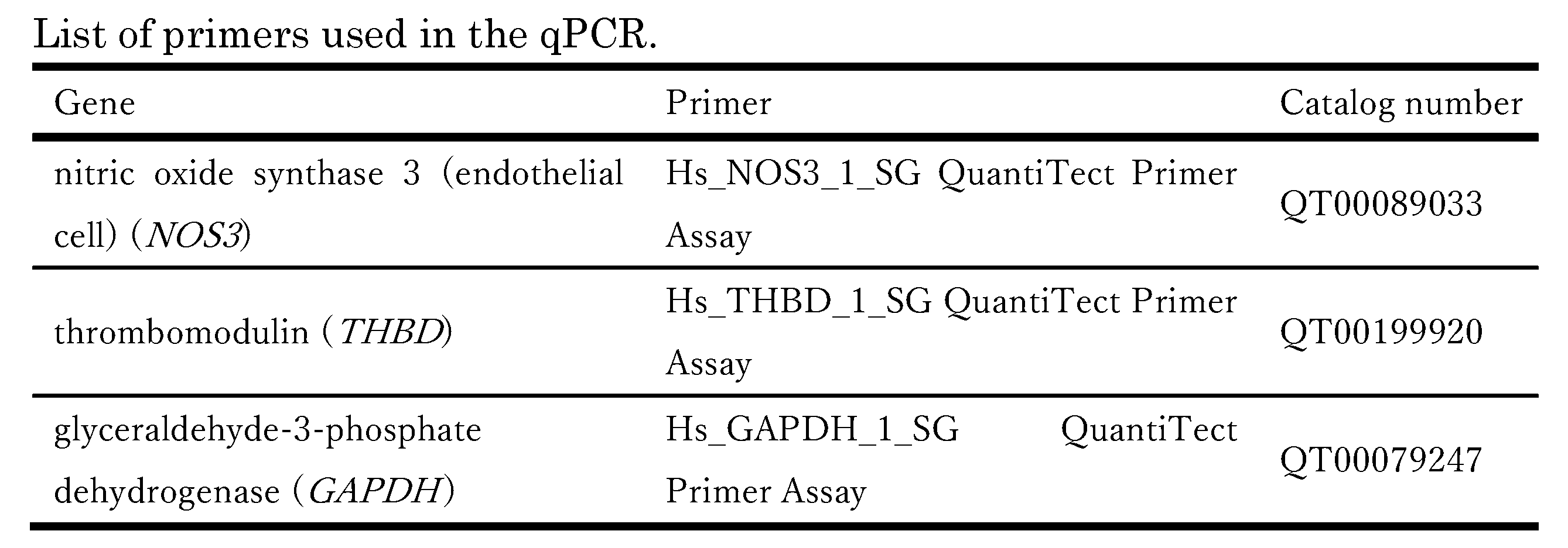
図22に遺伝子発現解析の結果を示す。図22は、2日間の培養後のHUVECにおけるTHBD及びNOS3の相対的なmRNA発現レベルを示すグラフである。図22において、白抜きのグラフは比較例、ハッチングしたグラフは実施例をそれぞれ示す。
実施例の細胞培養装置で培養したHUVECは比較例の6ウェルプレートで培養した場合と比較して、THBDの発現が3.3倍向上し、NOS3の発現が5倍向上したことが確認された。このことにより、実施例のフィルタ層のラプラスバルブを用いた流路構成により、細胞に培養液の流れ刺激を負荷して培養可能であることが確認された。
実施例の細胞培養装置で培養したHUVECは比較例の6ウェルプレートで培養した場合と比較して、THBDの発現が3.3倍向上し、NOS3の発現が5倍向上したことが確認された。このことにより、実施例のフィルタ層のラプラスバルブを用いた流路構成により、細胞に培養液の流れ刺激を負荷して培養可能であることが確認された。
本発明の細胞培養装置及びその製造方法を利用すれば、創薬における医薬品候補化合物の薬効試験、安全性試験、薬物動態評価試験といった試験を、培養細胞を用いて行うことが可能となる。また、本発明は、食品、化成品、化粧品等の機能や安全性を評価するための動物実験代替法としても利用することができる。さらに、本発明において開示する構造を有する細胞培養装置として販売されることや、細胞培養装置を利用した検査装置としても利用することができる。
1…細胞培養装置、2…チャンバ層(貯留部)、3…流路プレート(流路形成部)、4…細胞培養部、5…加圧調整装置(循環流れ制御部)、6…気体流入防止部、6a…面状構造体(面状の構造体)、6h…貫通孔、20A-20D…第1空間(第2空間)、30…フィルタ層(フィルタ部)31…第1気体流入防止部(気体流入防止部)、31h…貫通孔、32…第2気体流入防止部(気体流入防止部)、32h…貫通孔、33…フィルタ窓孔、34…貫通孔、40…第1流路層(流路形成体)、41,42…第1流路層における貫通孔、43,44…第1流路層において培養液の循環流れを形成する流路、50…第2流路層(流路形成体)、51,52…第2流路層における貫通孔、53,54…第2流路層において培養液の循環流れを形成する流路、60…多孔質膜層、60a…第1面、60b…第2面、61,62…多孔質膜層における貫通孔、70…第3流路層(流路形成体)、71,72…第3流路層における貫通孔、73,74…第3流路層において培養液の循環流れを形成する流路、80…第4流路層(流路形成体)、83,84…第4流路層において培養液の循環流れを形成する流路、91…空圧ポンプ、130…トラックエッチ膜、230…ハニカムフィルム、330…フィルタ層(フィルタ部)、330a…面状構造体(面状の構造体)、330h…貫通孔、331…気体流入防止部、340…流路層(流路形成体)、530…フィルタ層(フィルタ部)W1A,W2A…送液流路(培養液の循環流れを形成する流路)、W1B,W2B…返送流路(培養液の循環流れを形成する流路)
Claims (11)
- 液体培地を貯留可能な第1空間及び第2空間を有する貯留部と、
前記第1空間及び前記第2空間を互いに連通する第1流路及び第2流路を有する流路形成部と、
前記第1空間、前記第2空間、前記第1流路及び前記第2流路の少なくとも一部に設けられる細胞培養部と、
前記第1空間又は前記第2空間から前記第1流路又は前記第2流路を経て前記第1空間又は前記第2空間に戻る培養液の循環流れを制御するための循環流れ制御部と、
を備え、
前記流路形成部は、
前記第1流路及び前記第2流路が形成された少なくとも1つの流路形成体と、
少なくとも1つの貫通孔が形成され前記循環流れにおける気体の流入を防止する領域である気体流入防止部が1以上設けられたフィルタ部と、を有する、細胞培養装置。 - 前記気体流入防止部は、前記第1流路の端部又は前記第2流路の端部に設けられる、請求項1に記載の細胞培養装置。
- 前記貯留部、前記少なくとも1つの流路形成体及び前記気体流入防止部は、それぞれ層状に形成されており、
前記少なくとも1つの流路形成体、前記フィルタ部、前記貯留部の順に積層されている、
請求項1又は2に記載の細胞培養装置。 - 前記貫通孔の直径は、0.005mm以上0.2mm以下である、
請求項1又は2に記載の細胞培養装置。 - 前記貯留部は、空気を供給可能な空圧ポンプに接続されている、
請求項1又は2に記載の細胞培養装置。 - 前記フィルタ部の少なくとも一部は、感光性のフォトレジストによって構成されており、
前記少なくとも1つの貫通孔は、前記フォトレジストに形成されている、
請求項1又は2に記載の細胞培養装置。 - 前記気体流入防止部の少なくとも一部は、ポリイミド、ポリカーボネート又はポリエステル製のトラックエッチ膜で構成されている、
請求項1又は2に記載の細胞培養装置。 - 前記気体流入防止部の少なくとも一部は、ハニカムフィルムで構成されている、
請求項1又は2に記載の細胞培養装置。 - 前記細胞培養部は、前記第2流路及び/又は前記第2流路に設けられている、
請求項1又は2に記載の細胞培養装置。 - 前記流路形成部は、細胞を培養するための第1面と前記第1面とは反対の第2面とを有する多孔質膜層を更に有しており、
前記少なくとも1つの流路形成体は、前記多孔質膜層の前記第1面の側に配置される第1流路層及び第2流路層と、前記多孔質膜層の前記第2面の側に配置される第3流路層及び第4流路層と、を含み、
前記第1流路層及び前記第2流路層は、前記多孔質膜層の前記第1面の側において、前記第1空間又は前記第2空間から前記第1流路又は前記第2流路を経て前記第1空間又は前記第2空間に戻る前記培養液の循環流れを形成する流路を含み、
前記第3流路層及び前記第4流路層は、前記多孔質膜層の前記第2面の側において、前記第1空間又は前記第2空間から前記第1流路又は前記第2流路を経て前記第1空間又は前記第2空間に戻る前記培養液の循環流れを形成する流路を含む、
請求項9に記載の細胞培養装置。 - 液体培地を貯留可能な第1空間及び第2空間を有する貯留部と、前記第1空間及び前記第2空間を互いに連通する第1流路及び第2流路を有する流路形成部と、前記第1空間、前記第2空間、前記第1流路及び前記第2流路の少なくとも一部に設けられる細胞培養部と、前記第1空間又は前記第2空間から前記第1流路又は前記第2流路を経て前記第1空間又は前記第2空間に戻る培養液の循環流れを制御するための循環流れ制御部と、
を備える細胞培養装置の製造方法であって、
前記貯留部を層状に形成し、
前記第1流路及び前記第2流路が形成された少なくとも1つの流路形成体と、少なくとも1つの貫通孔が形成され前記循環流れにおける気体の流入を防止する領域である気体流入防止部が1以上設けられたフィルタ部とを有する前記流路形成部を、前記少なくとも1つの流路形成体と前記フィルタ部とがそれぞれ層状となるように形成し、
前記少なくとも1つの流路形成体、前記フィルタ部、前記貯留部をこの順に積層して接合する、
細胞培養装置の製造方法。
Applications Claiming Priority (2)
| Application Number | Priority Date | Filing Date | Title |
|---|---|---|---|
| JP2022-138716 | 2022-08-31 | ||
| JP2022138716A JP2024034473A (ja) | 2022-08-31 | 2022-08-31 | 細胞培養装置及びその製造方法 |
Publications (1)
| Publication Number | Publication Date |
|---|---|
| WO2024048716A1 true WO2024048716A1 (ja) | 2024-03-07 |
Family
ID=90099818
Family Applications (1)
| Application Number | Title | Priority Date | Filing Date |
|---|---|---|---|
| PCT/JP2023/031800 Ceased WO2024048716A1 (ja) | 2022-08-31 | 2023-08-31 | 細胞培養装置及びその製造方法 |
Country Status (2)
| Country | Link |
|---|---|
| JP (1) | JP2024034473A (ja) |
| WO (1) | WO2024048716A1 (ja) |
Citations (2)
| Publication number | Priority date | Publication date | Assignee | Title |
|---|---|---|---|---|
| WO2016158233A1 (ja) * | 2015-04-03 | 2016-10-06 | 国立研究開発法人産業技術総合研究所 | 細胞培養装置および細胞培養方法 |
| US20180200677A1 (en) * | 2015-04-24 | 2018-07-19 | The Regents Of The University Of California | Hemolysis-free blood plasma separation |
-
2022
- 2022-08-31 JP JP2022138716A patent/JP2024034473A/ja active Pending
-
2023
- 2023-08-31 WO PCT/JP2023/031800 patent/WO2024048716A1/ja not_active Ceased
Patent Citations (2)
| Publication number | Priority date | Publication date | Assignee | Title |
|---|---|---|---|---|
| WO2016158233A1 (ja) * | 2015-04-03 | 2016-10-06 | 国立研究開発法人産業技術総合研究所 | 細胞培養装置および細胞培養方法 |
| US20180200677A1 (en) * | 2015-04-24 | 2018-07-19 | The Regents Of The University Of California | Hemolysis-free blood plasma separation |
Also Published As
| Publication number | Publication date |
|---|---|
| JP2024034473A (ja) | 2024-03-13 |
Similar Documents
| Publication | Publication Date | Title |
|---|---|---|
| JP5801311B2 (ja) | 細胞培養用のマイクロスケール多流体流バイオリアクタ | |
| CN101061213B (zh) | 灌注的三维细胞/组织疾病模型 | |
| AU2006304634B2 (en) | Microfluidic cell culture device and method for using same | |
| US9388374B2 (en) | Microfluidic cell culture systems | |
| US10926254B2 (en) | Membrane-integrated microfluid device for imaging cells | |
| US20140273223A1 (en) | Micro-device for culturing cells, method for manufacturing same, and method for culturing cells using the micro-device for culturing cells | |
| US20130344529A1 (en) | Vascular model, method for producing said model and use thereof | |
| WO2008028241A1 (en) | Microbioreactor | |
| JP7150341B2 (ja) | 細胞培養装置および細胞培養方法 | |
| JPWO2017154880A1 (ja) | 細胞培養装置および細胞培養方法 | |
| JP6823793B2 (ja) | 細胞培養装置および細胞培養方法 | |
| JPS59175877A (ja) | 培養方法および培養システム | |
| US20100323447A1 (en) | Microfluidic cell culture device and method for using same | |
| CN116685670A (zh) | 微流控细胞培养装置 | |
| US11745183B2 (en) | Microtiter plate and uses thereof | |
| WO2010013016A2 (en) | Apparatus and method for sample processing or storage | |
| WO2011135339A2 (en) | Reactor | |
| Sugiura et al. | Perfusion culture of endothelial cells under shear stress on microporous membrane in a pressure-driven microphysiological system | |
| WO2024048716A1 (ja) | 細胞培養装置及びその製造方法 | |
| JP2005528212A (ja) | 湿度および気体流体能を有する物質および反応器システム | |
| CN212999366U (zh) | 微过滤器及微过滤单元 | |
| JP4674337B2 (ja) | 細胞観察用デバイス及び細胞観察方法 | |
| KR102677415B1 (ko) | 저산소 상태의 모사가 가능한 미세유체칩 | |
| FI129674B (en) | Device and method for cell culture | |
| US20180264474A1 (en) | Folded Multi-Material Microfluidic Devices for Tissue Engineering |
Legal Events
| Date | Code | Title | Description |
|---|---|---|---|
| 121 | Ep: the epo has been informed by wipo that ep was designated in this application |
Ref document number: 23860478 Country of ref document: EP Kind code of ref document: A1 |
|
| NENP | Non-entry into the national phase |
Ref country code: DE |
|
| 122 | Ep: pct application non-entry in european phase |
Ref document number: 23860478 Country of ref document: EP Kind code of ref document: A1 |