WO2024048442A1 - プリフォームの製造装置、製造方法および冷却用金型 - Google Patents
プリフォームの製造装置、製造方法および冷却用金型 Download PDFInfo
- Publication number
- WO2024048442A1 WO2024048442A1 PCT/JP2023/030694 JP2023030694W WO2024048442A1 WO 2024048442 A1 WO2024048442 A1 WO 2024048442A1 JP 2023030694 W JP2023030694 W JP 2023030694W WO 2024048442 A1 WO2024048442 A1 WO 2024048442A1
- Authority
- WO
- WIPO (PCT)
- Prior art keywords
- preform
- mold
- cooling
- section
- injection molding
- Prior art date
- Legal status (The legal status is an assumption and is not a legal conclusion. Google has not performed a legal analysis and makes no representation as to the accuracy of the status listed.)
- Ceased
Links
Images


Classifications
-
- B—PERFORMING OPERATIONS; TRANSPORTING
- B29—WORKING OF PLASTICS; WORKING OF SUBSTANCES IN A PLASTIC STATE IN GENERAL
- B29B—PREPARATION OR PRETREATMENT OF THE MATERIAL TO BE SHAPED; MAKING GRANULES OR PREFORMS; RECOVERY OF PLASTICS OR OTHER CONSTITUENTS OF WASTE MATERIAL CONTAINING PLASTICS
- B29B13/00—Conditioning or physical treatment of the material to be shaped
- B29B13/04—Conditioning or physical treatment of the material to be shaped by cooling
-
- B—PERFORMING OPERATIONS; TRANSPORTING
- B29—WORKING OF PLASTICS; WORKING OF SUBSTANCES IN A PLASTIC STATE IN GENERAL
- B29B—PREPARATION OR PRETREATMENT OF THE MATERIAL TO BE SHAPED; MAKING GRANULES OR PREFORMS; RECOVERY OF PLASTICS OR OTHER CONSTITUENTS OF WASTE MATERIAL CONTAINING PLASTICS
- B29B11/00—Making preforms
- B29B11/06—Making preforms by moulding the material
- B29B11/08—Injection moulding
-
- B—PERFORMING OPERATIONS; TRANSPORTING
- B29—WORKING OF PLASTICS; WORKING OF SUBSTANCES IN A PLASTIC STATE IN GENERAL
- B29C—SHAPING OR JOINING OF PLASTICS; SHAPING OF MATERIAL IN A PLASTIC STATE, NOT OTHERWISE PROVIDED FOR; AFTER-TREATMENT OF THE SHAPED PRODUCTS, e.g. REPAIRING
- B29C45/00—Injection moulding, i.e. forcing the required volume of moulding material through a nozzle into a closed mould; Apparatus therefor
-
- B—PERFORMING OPERATIONS; TRANSPORTING
- B29—WORKING OF PLASTICS; WORKING OF SUBSTANCES IN A PLASTIC STATE IN GENERAL
- B29C—SHAPING OR JOINING OF PLASTICS; SHAPING OF MATERIAL IN A PLASTIC STATE, NOT OTHERWISE PROVIDED FOR; AFTER-TREATMENT OF THE SHAPED PRODUCTS, e.g. REPAIRING
- B29C49/00—Blow-moulding, i.e. blowing a preform or parison to a desired shape within a mould; Apparatus therefor
- B29C49/42—Component parts, details or accessories; Auxiliary operations
- B29C49/64—Heating or cooling preforms, parisons or blown articles
- B29C49/6409—Thermal conditioning of preforms
- B29C49/6427—Cooling of preforms
- B29C49/643—Cooling of preforms from the inside
-
- B—PERFORMING OPERATIONS; TRANSPORTING
- B29—WORKING OF PLASTICS; WORKING OF SUBSTANCES IN A PLASTIC STATE IN GENERAL
- B29C—SHAPING OR JOINING OF PLASTICS; SHAPING OF MATERIAL IN A PLASTIC STATE, NOT OTHERWISE PROVIDED FOR; AFTER-TREATMENT OF THE SHAPED PRODUCTS, e.g. REPAIRING
- B29C49/00—Blow-moulding, i.e. blowing a preform or parison to a desired shape within a mould; Apparatus therefor
- B29C49/42—Component parts, details or accessories; Auxiliary operations
- B29C49/64—Heating or cooling preforms, parisons or blown articles
- B29C49/6409—Thermal conditioning of preforms
- B29C49/6463—Thermal conditioning of preforms by contact heating or cooling, e.g. mandrels or cores specially adapted for heating or cooling preforms
- B29C49/6465—Cooling
-
- B—PERFORMING OPERATIONS; TRANSPORTING
- B29—WORKING OF PLASTICS; WORKING OF SUBSTANCES IN A PLASTIC STATE IN GENERAL
- B29C—SHAPING OR JOINING OF PLASTICS; SHAPING OF MATERIAL IN A PLASTIC STATE, NOT OTHERWISE PROVIDED FOR; AFTER-TREATMENT OF THE SHAPED PRODUCTS, e.g. REPAIRING
- B29C49/00—Blow-moulding, i.e. blowing a preform or parison to a desired shape within a mould; Apparatus therefor
- B29C49/02—Combined blow-moulding and manufacture of the preform or the parison
- B29C2049/023—Combined blow-moulding and manufacture of the preform or the parison using inherent heat of the preform, i.e. 1 step blow moulding
Definitions
- the present invention relates to a preform manufacturing apparatus, a manufacturing method, and a cooling mold.
- the preform in the injection mold if the cooling time of the preform in the injection mold is shortened, the preform will be released from the injection mold at a higher temperature than usual, making it easier for the preform to shrink and deform. Decreased dimensional accuracy and poor appearance (sink marks) are likely to occur.
- the preform that is released from the mold at high temperatures is very soft, so if air is blown into the bottom of the preform during cooling, the bottom of the preform that is hit by the air will be deformed by the air pressure, reducing dimensional accuracy. There is a possibility.
- an object of the present invention is to provide a preform manufacturing apparatus that can suppress a decrease in dimensional accuracy of a preform released from an injection molding section at high temperature. do.
- a preform manufacturing apparatus includes an injection molding section for injection molding a bottomed cylindrical resin preform using an injection mold, and a cooling section for cooling the preform manufactured by the injection molding section.
- the apparatus includes a cooling section and a take-out section for taking out the preform cooled in the post-cooling section to the outside of the apparatus.
- the post-cooling section includes a first mold that houses the preform inside and contacts the outer surface of the preform, a cooling rod that is inserted into the preform and has a compressed air flow path inside, and a tip of the cooling rod. a second mold comprising at least a tip piece attached to the side.
- the tip piece corresponds to the shape of the bottom of the preform, and includes a mold surface that receives the bottom, and an opening that is formed on the proximal side of the mold surface and communicates with the compressed air flow path.
- the post-cooling section cools the bottom of the preform with the mold surface of the tip piece pressed against the first mold, and cools the body of the preform into the first mold using compressed air passing through the opening. Cool the body while pressing it against the mold.
- a preform manufacturing apparatus that can suppress a decrease in dimensional accuracy of a preform released from an injection molding section at high temperature.
- FIG. 1 is a diagram showing a configuration example of an injection molding apparatus according to the present embodiment. It is a figure which shows the example of a structure of the post-cooling part of FIG.
- FIG. 3 is a perspective view showing the tip portion of the cooling rod in FIG. 2;
- FIG. 2 is a diagram illustrating a configuration example of a take-out section in FIG. 1;
- 3 is a flowchart showing steps of a method for manufacturing a preform.
- FIG. 1 is a diagram showing a configuration example of an injection molding apparatus 10 according to the present embodiment.
- the injection molding apparatus 10 of this embodiment is a manufacturing apparatus used to manufacture a resin preform 1 at high speed.
- the overall shape of the preform 1 is a bottomed cylindrical shape with one end open and the other end closed, as shown in FIGS. 2 and 4 described later.
- the preform 1 includes a cylindrical body 3, a bottom 4 that closes the other end of the body 3, and a neck 2 formed on the open side of one end of the body 3. .
- the injection molding apparatus 10 includes an injection molding section 11, a post-cooling section 12, a take-out section 13, a transfer plate 14 as a transport mechanism, and an injection device 15. Further, the injection molding apparatus 10 includes a machine stand 10a, an upper base 10b, a lower base 10c, and an injection core type movable platen 10d. A lower base plate 10c and an injection device 15 are arranged above the machine stand 10a.
- the upper base 10b is erected above the lower base 10c via a guide rod, and is arranged to be vertically movable up and down with respect to the lower base 10c.
- the injection core type movable platen 10d is erected above the upper base plate 10b via a guide rod, and is arranged to be vertically movable up and down with respect to the upper base plate 10b.
- the transfer plate 14 is rotatably supported on the lower surface of the upper base 10b.
- through holes are formed in the upper base 10b and the transfer plate 14 at positions corresponding to the injection molding section 11, the post-cooling section 12, and the take-out section 13. This allows the injection core mold (not shown), the cooling rod 22, the fitting core 23, the extraction core 31, and the air introduction pipe 32 to approach or insert into the preform 1 and the neck mold 16.
- the injection molding apparatus 10 supports the neck part 2 of the preform 1 with a neck mold 16 (described later), and maintains the neck part 2 always facing upward, and the injection molding part 11, the post-cooling part 12, and the take-out part. It is intermittently transported to each of the 13 molding sections (each process).
- the injection molding section 11, the post-cooling section 12, and the take-out section 13 are arranged above the machine stand 10a or the lower base plate 10c.
- the injection molding section 11, the post-cooling section 12, and the take-out section 13 are arranged at positions rotated by a predetermined angle (for example, 120 degrees) with respect to the rotation center of the transfer plate 14 with respect to the machine stand 10a or the lower base plate 10c. There is.
- the transfer plate 14 is composed of a single disk-shaped flat plate member or a plurality of substantially fan-shaped flat plate members divided for each forming station.
- the neck mold 16 is composed of a pair of neck split molds 16a.
- the neck-type fixing plate 17 is composed of a pair of dividing plates 17a that can be moved into and out of contact with each other.
- the neck split molds 16a are each fixed to the dividing plates 17a, and open and close in the horizontal direction as the dividing plates 17a move toward and away from each other.
- the transfer plate 14 is moved in the rotational direction by a transfer mechanism (not shown) equipped with a rotation mechanism (the transfer plate 14 rotates about the central axis (rotation axis) of the transfer plate 14), and the neck mold 16 (or neck The preform 1 with the neck portion 2 held by the mold fixing plate 17) is transported to the injection molding section 11, the post-cooling section 12, and the take-out section 13 in this order.
- the above-mentioned transport mechanism further includes a lifting mechanism (vertical mold opening/closing mechanism), and performs the operation of lifting and lowering the transfer plate 14 (or the upper base 10b that supports the transfer plate 14) and the injection core mold movable platen 10d. , also performs operations related to mold closing and mold opening (mold release) in the injection molding section 11 and the like.
- the injection molding section 11 includes an injection cavity mold 11a having a plurality of cavities and an injection core mold fixing plate 11b having a plurality of injection core molds (not shown), and manufactures the preform 1 by injection molding.
- An injection device 15 that supplies raw materials (resin material) for the preform 1 is connected to the injection molding section 11 .
- the injection cavity mold 11a, the injection core mold, and the neck mold 16 of the transfer plate 14 are closed to form a preform-shaped mold space. Then, the preform 1 is manufactured in the injection molding section 11 by injecting the resin material from the injection device 15 into such a mold space.
- the material of the preform 1 described above is a thermoplastic synthetic resin, and can be appropriately selected depending on the use of the container.
- Specific types of materials include, for example, PET (polyethylene terephthalate), PEN (polyethylene naphthalate), PCTA (polycyclohexane dimethylene terephthalate), Tritan (tritan: copolyester), PP (polypropylene), PE (polyethylene).
- PC polycarbonate
- PES polyether sulfone
- PPUS polyphenylsulfone
- PS polystyrene
- COP/COC cyclic olefin polymer
- PMMA polymethyl methacrylate: acrylic
- PLA polylactic acid
- the neck mold 16 of the transfer plate 14 is also opened (the mold is opened). ), the preform 1 is held and transported as is.
- the number of preforms 1 molded simultaneously in the injection molding section 11 (the number N ⁇ M shown below) can be set as appropriate. For example, when the number of rows (N) of the neck mold fixing plates 17 is three, and the number of neck molds fixed to one neck mold fixing plate 17 is 16 (M), the injection molding section 11 simultaneously molds the neck molds.
- the number of preforms 1 to be produced is 48.
- the post-cooling section 12 has a function of cooling the preform 1 that is in a high temperature state and is conveyed from the injection molding section 11 .
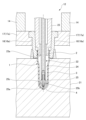
- FIG. 2 is a diagram showing an example of the configuration of the post-cooling section 12.
- the post-cooling section 12 includes a cooling cavity mold (cooling pot) 21, a cooling rod 22, and a fitting core (first core mold) 23 as a mold unit for cooling the preform 1.
- the cooling cavity mold 21 is an example of a first mold.
- the cooling rod 22, the fitting core 23, and the tip piece 25 described below are an example of a second mold. Note that the number of cooling spaces, cooling rods 22, tip pieces 25, and fitting cores 23 (described later) of the cooling cavity mold 21 is preferably the same as the number of preforms 1 molded at one time in the injection molding section 11. .
- the cooling cavity mold 21 is a mold having a cooling space (accommodating space for the preform 1) having approximately the same shape as the preform 1 manufactured in the injection molding section 11.
- the cooling cavity mold 21 accommodates the preform 1 in an inner receiving space and contacts the outer surface of the preform 1.
- a flow path (not shown) through which a temperature adjusting medium (refrigerant) flows is formed inside the cooling cavity mold 21 . Therefore, the temperature of the cooling cavity mold 21 is maintained at a predetermined temperature by the temperature adjusting medium.
- the temperature of the temperature adjusting medium of the cooling cavity mold 21 is not particularly limited, but can be appropriately selected within the range of 5° C. to 80° C., for example.
- Both the cooling rod 22 and the fitting core 23 are hollow cylindrical bodies, and the cooling rod 22 is arranged concentrically inside the fitting core 23. Further, the cooling rod 22 and the fitting core 23 are inserted inside the neck mold 16 and the preform 1.
- the fitting core 23 When the fitting core 23 is inserted into the neck mold 16, its tip comes into close contact with the inner periphery or upper end surface of the neck 2 of the preform 1 to maintain airtightness with the preform 1. Furthermore, an opening 23a is formed at the tip of the fitting core 23 for exhausting air from within the preform 1.
- the space between the cooling rod 22 and the fitting core 23 constitutes an exhaust flow path connected to an air exhaust section (not shown).
- the cooling rod 22 includes a cylindrical main body 24, and a tip piece 25 is attached to the tip of the main body 24.
- the cooling rod 22 is inserted into the interior of the preform 1 until the tip piece 25 abuts the bottom 4 of the preform 1. Further, the inside of the main body portion 24 of the cooling rod 22 constitutes an air supply flow path for guiding compressed air (air, gaseous refrigerant) from an air supply portion (not shown).
- FIGS. 3(a) and 3(b) are perspective views showing the tip portion of the cooling rod 22.
- the tip piece 25 of the cooling rod 22 is a mold component that has a curved mold surface 25a corresponding to the shape of the inner peripheral side of the bottom 4 of the preform 1 on the tip side.
- the tip piece 25 is preferably formed of a material with high thermal conductivity, such as aluminum or aluminum alloy.
- the mold surface 25a of the tip piece 25 has the function of receiving the bottom 4 of the preform 1 and pressing the bottom 4 from the inside, thereby pressing the bottom 4 of the preform 1 against the inner surface of the cooling cavity mold 21.
- an air flow path 25b is formed in the tip piece 25 and communicates with the air supply flow path of the main body portion 24.
- the air flow path 25b of the tip piece 25 branches near the tip of the tip piece 25 and is folded back toward the base end side of the tip piece 25 (upper side in the figure, toward the body of the preform).
- the plurality of branched air channels 25b are arranged at equal intervals in the circumferential direction of the tip piece 25, and are connected to air jet ports 25c (openings) formed on the proximal side of the mold surface 25a of the tip piece 25. They are connected to each other.
- Each air outlet 25c is arranged so as to face the space between the preform 1 and the main body 24 of the cooling rod 22.
- the take-out part 13 is configured to release the neck part 2 of the preform 1 cooled in the post-cooling part 12 from the neck mold 16 and take out the preform 1 to the outside of the injection molding apparatus 10. Furthermore, the take-out section 13 in this embodiment has an air injection function for cooling and taking out the preform 1.
- FIG. 4 is a diagram showing an example of the configuration of the take-out section 13.
- the take-out section 13 includes a take-out core (second core mold) 31, an air introduction pipe 32, and a mold opening cam (not shown).
- the take-out core 31 and the air introduction pipe 32 are an example of an auxiliary cooling section.
- Both the take-out core 31 and the air introduction pipe 32 are hollow cylindrical bodies, and the air introduction pipe 32 is arranged concentrically inside the take-out core 31. Further, the air introduction pipe 32 and the take-out core 31 are inserted inside the neck mold 16 and the preform 1.
- a ring-shaped airtight member 31b is provided at the distal end of the take-out core 31 and contacts the upper end surface of the neck portion 2 in an airtight manner.
- the airtight member 31b may be omitted.
- an opening 31a is formed at the tip of the take-out core 31 for exhausting air from within the preform 1.
- the space between the air introduction pipe 32 and the take-out core 31 constitutes an exhaust flow path connected to an air exhaust section (not shown).
- the inside of the air introduction pipe 32 constitutes a flow path that guides compressed air (air, gaseous refrigerant) from an air supply section (not shown).
- An opening 32 a for introducing compressed air into the preform 1 is formed at the tip of the air introduction pipe 32 . Further, the tip of the air introduction pipe 32 is inserted up to the vicinity of the bottom 4 of the preform 1.
- two sets of mold opening cams each having a wedge-shaped tip operate independently of the take-out core 31 and the air introduction pipe 32, and open the pair of neck split molds 16a in the closed state into the preform 1. Separate them in the direction that intersects with the axial direction.
- the mold opening cam may be inserted into cam grooves (not shown) located at both ends of the pair of dividing plates 17a in the mold closed state, or cam followers (not shown) provided on the dividing plates 17a instead of the cam grooves. (shown).
- the neck mold 16 can be brought into an open state.
- the neck mold 16 is normally maintained in the closed state by being biased by a spring built into the pair of dividing plates 17a (or the neck mold fixing plate 17).
- the number of takeout cores 31 and air introduction pipes 32 is preferably the same as the number of preforms 1 molded at one time in the injection molding section 11.
- FIG. 5 is a flowchart showing the steps of the method for manufacturing the preform 1.
- Step S1 Injection molding process
- the injection core mold movable platen 10d and the transfer plate 14 are lowered, and the exit cavity mold, the injection core mold, and the neck mold 16 are closed.
- resin is injected from the injection device 15 into the mold space of the preform shape formed by closing the mold, and the preform 1 is manufactured.
- the injection molds (injection cavity mold and injection core mold) of the injection molding section 11 are opened after a minimum cooling time provided after the injection (filling and holding pressure) of the resin material is completed.
- step S1 the preform 1 is cooled in the injection mold after the injection of the resin material (filling and pressure holding) is completed. It is preferable to open the mold without providing any time (for example, the cooling time of the injection molding conditions set in the injection molding apparatus 10 is set to 0 seconds). In the above case, since the preform 1 is not cooled in the injection mold without holding pressure, it is possible to suppress the occurrence of sink marks caused by shrinkage of the preform 1 during the cooling time.
- the time (cooling time) for cooling the resin material within the mold after the injection of the resin material is completed in the injection molding section 11 is It is preferable that the time for injecting the material is 1/2 or less of the time for injecting the material (injection time (including pressure holding time)). Further, the cooling time is more preferably 2/5 or less, even more preferably 1/4 or less, and particularly preferably 1/5 or less of the injection time of the resin material (for example, the cooling time is preferably 1/5 or less).
- the cooling time of the injection molding conditions is set to 1/2 or less, 2/5 or less, 1/4 or less, or 1/5 or less of the injection time).
- step S1 when the injection core mold movable platen 10d and the transfer plate 14 (or the upper base plate 10b) are raised and the injection mold is opened, the preform 1 is transferred to the injection cavity mold at a high temperature that maintains its outer shape. and released from the injection core mold.
- the transfer plate 14 is moved to rotate by a predetermined angle, and the preform 1 held in the neck die 16 in a high temperature state is transferred to the post-cooling section 12.
- Step S2 Post-cooling process
- the preform 1 is cooled in the post-cooling section 12. Since the high-temperature preform 1 is rapidly cooled in the post-cooling section 12, whitening (white turbidity) due to spherulite formation and crystallization that may occur when the preform 1 is slowly cooled is thereby suppressed.
- the preform 1 is first accommodated in the accommodation space of the cooling cavity mold 21 by lowering the transfer plate 14 (or the upper base 10b). Subsequently, the cooling rod 22 and the fitting core 23 are lowered from the first standby position where they do not interfere with the transfer plate 14 and inserted into the preform 1 housed in the cooling cavity mold 21 .
- the fitting core 23 is in close contact with the neck portion 2 of the preform 1, and airtightness is maintained between the preform 1 and the fitting core 23.
- the cooling rod 22 is inserted into the preform 1.
- the mold surface 25a at the tip of the tip piece 25 presses the bottom 4 of the preform 1 downward, and the bottom 4 of the preform 1 is pressed against the cooling cavity mold 21.
- the bottom part 4 of the preform 1 in the post-cooling section 12 is sandwiched between the tip piece 25 and the cooling cavity mold 21, and is in close contact with both molds. Therefore, in the post-cooling section 12, the bottom part 4 of the preform 1 is cooled by heat exchange between the tip piece 25 on the inner surface side and the cooling cavity mold 21 on the outer surface side.
- the tip piece 25 of the cooling rod 22 presses the bottom 4 of the preform 1 from the inside, thereby suppressing irregular shrinkage and deformation of the preform 1. Furthermore, since the bottom part 4 of the preform 1 is in close contact with the tip piece 25 and the cooling cavity mold 21, the bottom part 4 of the preform 1 is held in a shape that follows the mold surface 25a of the tip piece 25 and the cooling cavity mold 21. Ru. Thereby, the shape accuracy (dimensional accuracy) of the bottom portion 4 of the preform 1 can be improved.
- cooling blowing of the preform 1 is performed.
- compressed air is introduced into the preform 1 from the air outlet 25c through the flow path in the cooling rod 22 and the air flow path 25b of the tip piece 25, and the compressed air is introduced into the preform 1 from the air outlet 25c to Compressed air is exhausted from the opening 23a between the two.
- the body 3 of the preform 1 is pressed against the cooling cavity mold 21. Therefore, in the post-cooling section 12 , the inner surface of the body 3 of the preform 1 is cooled by contact with the compressed air, and the outer surface is cooled by heat exchange with the cooling cavity mold 21 . Further, the body 3 of the preform 1 is held in a shape that follows the contour of the accommodation space of the cooling cavity mold 21.
- the air outlet 25c of the tip piece 25 faces the space between the preform 1 and the main body portion 24 of the cooling rod 22, the air outlet 25c is arranged not to face the inner surface of the preform 1. Therefore, the compressed air injected from the air outlet 25c does not directly hit the bottom 4 or the body 3 of the preform 1. Therefore, it is possible to suppress the occurrence of deformation such as local depressions inside the preform 1 due to the pressure when the compressed air is ejected. As a result of the above, the shape accuracy of the bottom portion 4 and the body portion 3 of the preform 1 can be improved.
- compressed air is caused to flow through the air flow path 25b of the tip piece 25, so it is easy to cool the tip piece 25, which receives the heat of the bottom portion 4 of the preform 1. Therefore, even when manufacturing the preform 1 in a high-speed molding cycle, it is possible to suppress the temperature increase of the tip piece 25, and problems such as the preform 1 sticking to the tip piece 25, for example, are less likely to occur.
- the cooling rod 22 and the fitting core 23 rise and separate from the preform 1, and then the transfer plate 14 (or the upper base 10b) rises and removes the preform 1 from the preform 1.
- the reform 1 is released from the cooling cavity mold 21.
- the transfer plate 14 is moved to rotate by a predetermined angle, and the preform 1 held by the neck mold 16 is transferred to the take-out section 13. transported to.
- Step S3 Removal process
- the take-out core 31 and the air introduction pipe 32 are lowered from the second standby position where they do not interfere with the transfer plate 14, and the plate held by the neck mold 16 is removed. Inserted into Reform 1.
- the take-out core 31 is brought into close contact with the neck portion 2 of the preform 1, and airtightness is maintained between the preform 1 and the take-out core 31.
- compressed air is introduced into the preform 1 through the opening 32a of the air introduction pipe 32 to supplementally cool the inside of the preform 1.
- the injection time and injection pressure of compressed air for auxiliary cooling of the extraction section 13 may be set lower than those for the post-cooling section 12.
- the temperature of the preform 1 can be brought closer to room temperature, and deformation and dimensional accuracy reduction due to heat shrinkage of the preform 1 after being taken out can be more reliably prevented. It can be suppressed.
- compressed air flows from the air introduction pipe 32 toward the bottom part 4 of the preform 1 in the take-out part 13, but since the preform 1 has already been cooled in the post-cooling part 12, even if the compressed air hits the preform, There is almost no change in the shape of the bottom 4 of 1.
- the neck mold 16 is opened by the mold opening cam as shown by the arrow in FIG. Thereafter, by injecting compressed air from the air introduction pipe 32, the preform 1 is guided in the vertical direction and separated from the neck mold 16, and the preform 1 is taken out of the injection molding apparatus 10. Next, the take-out core 31 and the air introduction pipe 32 rise to the second standby position.
- the post-cooling unit 12 of the injection molding apparatus 10 of the present embodiment includes a cooling cavity mold 21 that accommodates the preform 1 inside and contacts the outer surface of the preform, and a cooling cavity mold 21 that is inserted into the preform 1 and has a flow path for compressed air.
- the cooling rod 22 has a cooling rod 22 inside thereof, and a tip piece 25 attached to the tip side of the cooling rod 22.
- the tip piece 25 has a mold surface 25a that corresponds to the bottom shape of the preform 1 and receives the bottom 4, and an air jet port 25c that is formed on the proximal end side of the mold surface 25a and communicates with the compressed air flow path. including.
- the post-cooling unit 12 cools the bottom part 4 of the preform 1 with the mold surface 25a of the tip piece 25 pressed against the cooling cavity mold 21, and cools the preform 1 with compressed air passing through the air outlet 25c.
- the body 3 is cooled while being pressed against the cooling cavity mold 21.
- the bottom part 4 of the preform 1 is cooled by heat exchange between the tip piece 25 on the inner surface side and the cooling cavity mold 21 on the outer surface side. Furthermore, by pressing the body 3 of the preform 1 against the cooling cavity mold 21 with the compressed air passing through the air outlet 25c, the inner surface of the body 3 of the preform 1 is cooled by contact with the compressed air. At the same time, the outer surface side is cooled by heat exchange with the cooling cavity mold 21. Therefore, the preform 1 released from the injection molding section 11 at a high temperature can be efficiently cooled in a short time, and a decrease in the dimensional accuracy of the preform 1 due to thermal contraction can be suppressed.
- the tip piece 25 presses the bottom portion 4 of the preform 1, thereby suppressing irregular shrinkage and deformation of the preform 1 that has been released from the mold at a high temperature.
- the shape of the bottom 4 of the preform 1 can be maintained by pressing it against the mold surface 25a of the tip piece 25 and the cooling cavity mold 21 during cooling.
- the body 3 of the preform 1 is cooled in a state where it is pressed against the cooling cavity mold 21 by compressed air passing through the air outlet 25c, thereby making the body 3 imitate the cooling cavity mold 21. It can hold its shape. Therefore, the preform 1, which is easily deformed by being released from the injection molding section 11 at a high temperature, is maintained in a desired shape during cooling, so that the dimensional accuracy of the shape of the preform 1 can be improved.
- the preform 1 can be released from the mold in the injection molding section 11 even in a high temperature state, and the cooling time of the preform 1 in the injection molding section 11 can be significantly shortened.
- the molding of the next preform 1 can be started early, so that the molding cycle time of the preform 1 can be shortened.
- the injection molding apparatus 10 supports the neck part 2 of the preform 1 with the neck die 16 from molding to removal, and maintains a state in which the neck part 2 is always facing upward and the body part 3 is always in the vertical direction. That is, the preform 1 is not molded horizontally in the injection molding section 11, and the preform 1 is not released from the neck mold 16 even when the preform 1 is conveyed or transferred.
- the preform molded under conditions of short cooling time and released from the injection mold is soft except for the neck portion 2, and the body portion 3 and bottom portion 4 are easily deformed.
- the body 3 and bottom 4 sag and bend under their own weight when released from the injection mold, making it impossible to mold the preform 1 in accordance with the standard or specifications.
- the preform 1 is separated from the neck mold 16 and transported/transferred between the injection molding section 11 and the post-cooling section 12, the body section 3 and the bottom section 4 are deformed due to vibration etc.
- the preform 1 cannot be accommodated in the cooling cavity mold 21 with good positional accuracy and cannot be cooled appropriately. Then, bending marks and deformation marks remain on the preform 1 after cooling.
- deformation of the preform 1 can be suppressed during release from the injection mold or during transfer, so the above-mentioned problems will not occur even if the molding cycle time is shortened. .
- the preform 1 is auxiliary cooled by injecting compressed air at the take-out section 13.
- the structure for injecting compressed air to the take-out part 13 may not be provided, and the preform 1 may not be auxiliary cooled by the take-out part 13.
Landscapes
- Engineering & Computer Science (AREA)
- Mechanical Engineering (AREA)
- Manufacturing & Machinery (AREA)
- Physics & Mathematics (AREA)
- Thermal Sciences (AREA)
- Moulds For Moulding Plastics Or The Like (AREA)
- Blow-Moulding Or Thermoforming Of Plastics Or The Like (AREA)
Priority Applications (3)
| Application Number | Priority Date | Filing Date | Title |
|---|---|---|---|
| CN202380071180.XA CN119998104A (zh) | 2022-08-29 | 2023-08-25 | 预成型坯的制造装置、制造方法以及冷却用模具 |
| JP2024544198A JPWO2024048442A1 (https=) | 2022-08-29 | 2023-08-25 | |
| US19/105,471 US20260001255A1 (en) | 2022-08-29 | 2023-08-25 | Preform manufacturing device, manufacturing method, and mold for cooling |
Applications Claiming Priority (2)
| Application Number | Priority Date | Filing Date | Title |
|---|---|---|---|
| JP2022-135656 | 2022-08-29 | ||
| JP2022135656 | 2022-08-29 |
Publications (1)
| Publication Number | Publication Date |
|---|---|
| WO2024048442A1 true WO2024048442A1 (ja) | 2024-03-07 |
Family
ID=90099815
Family Applications (1)
| Application Number | Title | Priority Date | Filing Date |
|---|---|---|---|
| PCT/JP2023/030694 Ceased WO2024048442A1 (ja) | 2022-08-29 | 2023-08-25 | プリフォームの製造装置、製造方法および冷却用金型 |
Country Status (4)
| Country | Link |
|---|---|
| US (1) | US20260001255A1 (https=) |
| JP (1) | JPWO2024048442A1 (https=) |
| CN (1) | CN119998104A (https=) |
| WO (1) | WO2024048442A1 (https=) |
Citations (2)
| Publication number | Priority date | Publication date | Assignee | Title |
|---|---|---|---|---|
| JP2005067206A (ja) * | 1998-03-31 | 2005-03-17 | Husky Injection Molding Systems Inc | 成形製品の冷却システムおよび冷却方法、冷却ピン |
| WO2020251035A1 (ja) * | 2019-06-12 | 2020-12-17 | 日精エー・エス・ビー機械株式会社 | プリフォーム、樹脂製容器およびそれらの製造方法 |
-
2023
- 2023-08-25 US US19/105,471 patent/US20260001255A1/en active Pending
- 2023-08-25 WO PCT/JP2023/030694 patent/WO2024048442A1/ja not_active Ceased
- 2023-08-25 CN CN202380071180.XA patent/CN119998104A/zh active Pending
- 2023-08-25 JP JP2024544198A patent/JPWO2024048442A1/ja active Pending
Patent Citations (2)
| Publication number | Priority date | Publication date | Assignee | Title |
|---|---|---|---|---|
| JP2005067206A (ja) * | 1998-03-31 | 2005-03-17 | Husky Injection Molding Systems Inc | 成形製品の冷却システムおよび冷却方法、冷却ピン |
| WO2020251035A1 (ja) * | 2019-06-12 | 2020-12-17 | 日精エー・エス・ビー機械株式会社 | プリフォーム、樹脂製容器およびそれらの製造方法 |
Also Published As
| Publication number | Publication date |
|---|---|
| JPWO2024048442A1 (https=) | 2024-03-07 |
| US20260001255A1 (en) | 2026-01-01 |
| CN119998104A (zh) | 2025-05-13 |
Similar Documents
| Publication | Publication Date | Title |
|---|---|---|
| CN121733792A (zh) | 树脂制的容器的制造方法、模具单元以及成型机 | |
| JP6777838B1 (ja) | 樹脂製容器の製造方法およびブロー成形装置 | |
| JP7457077B2 (ja) | 首曲がり容器の製造方法、温度調整用金型、ブロー成形装置およびブロー成形方法 | |
| US11472091B2 (en) | Two step blow molding unit, apparatus and method | |
| JP7259044B2 (ja) | 金型ユニット、ブロー成形装置およびブロー成形方法 | |
| CN108602230B (zh) | 用于注塑机的注塑和吹塑模具 | |
| US12208558B2 (en) | Manufacturing method and manufacturing apparatus for delamination container | |
| JP6864164B1 (ja) | ブロー成形装置およびブロー成形方法 | |
| WO2024048442A1 (ja) | プリフォームの製造装置、製造方法および冷却用金型 | |
| JP7682272B2 (ja) | 樹脂製容器の製造方法および温度調整装置 | |
| JP7797544B2 (ja) | 温度調整用金型、樹脂製容器の製造装置 | |
| JP7595196B2 (ja) | 温度調整用金型、樹脂製容器の製造装置および製造方法 | |
| EP4324620B1 (en) | Production method and production device for resin container | |
| EP4512591A1 (en) | Method and device for producing resin container | |
| US20250178266A1 (en) | Temperature adjustment mold, temperature adjustment method, and resin container manufacturing apparatus | |
| CN116761708B (zh) | 树脂制容器的制造方法以及制造装置 | |
| WO2025084209A1 (ja) | 温度調整用金型、樹脂製容器の製造装置および製造方法 |
Legal Events
| Date | Code | Title | Description |
|---|---|---|---|
| 121 | Ep: the epo has been informed by wipo that ep was designated in this application |
Ref document number: 23860204 Country of ref document: EP Kind code of ref document: A1 |
|
| WWE | Wipo information: entry into national phase |
Ref document number: 2024544198 Country of ref document: JP |
|
| WWE | Wipo information: entry into national phase |
Ref document number: 202517027674 Country of ref document: IN |
|
| NENP | Non-entry into the national phase |
Ref country code: DE |
|
| WWE | Wipo information: entry into national phase |
Ref document number: 202380071180.X Country of ref document: CN |
|
| WWP | Wipo information: published in national office |
Ref document number: 202517027674 Country of ref document: IN |
|
| WWP | Wipo information: published in national office |
Ref document number: 202380071180.X Country of ref document: CN |
|
| 122 | Ep: pct application non-entry in european phase |
Ref document number: 23860204 Country of ref document: EP Kind code of ref document: A1 |