WO2024048346A1 - 物体認識システム、物体認識装置及び物体認識方法 - Google Patents
物体認識システム、物体認識装置及び物体認識方法 Download PDFInfo
- Publication number
- WO2024048346A1 WO2024048346A1 PCT/JP2023/029980 JP2023029980W WO2024048346A1 WO 2024048346 A1 WO2024048346 A1 WO 2024048346A1 JP 2023029980 W JP2023029980 W JP 2023029980W WO 2024048346 A1 WO2024048346 A1 WO 2024048346A1
- Authority
- WO
- WIPO (PCT)
- Prior art keywords
- light source
- timing
- light
- object recognition
- image
- Prior art date
- Legal status (The legal status is an assumption and is not a legal conclusion. Google has not performed a legal analysis and makes no representation as to the accuracy of the status listed.)
- Ceased
Links
Images






Classifications
-
- G—PHYSICS
- G01—MEASURING; TESTING
- G01B—MEASURING LENGTH, THICKNESS OR SIMILAR LINEAR DIMENSIONS; MEASURING ANGLES; MEASURING AREAS; MEASURING IRREGULARITIES OF SURFACES OR CONTOURS
- G01B11/00—Measuring arrangements characterised by the use of optical techniques
- G01B11/24—Measuring arrangements characterised by the use of optical techniques for measuring contours or curvatures
-
- G—PHYSICS
- G01—MEASURING; TESTING
- G01C—MEASURING DISTANCES, LEVELS OR BEARINGS; SURVEYING; NAVIGATION; GYROSCOPIC INSTRUMENTS; PHOTOGRAMMETRY OR VIDEOGRAMMETRY
- G01C3/00—Measuring distances in line of sight; Optical rangefinders
- G01C3/02—Details
- G01C3/06—Use of electric means to obtain final indication
-
- G—PHYSICS
- G01—MEASURING; TESTING
- G01S—RADIO DIRECTION-FINDING; RADIO NAVIGATION; DETERMINING DISTANCE OR VELOCITY BY USE OF RADIO WAVES; LOCATING OR PRESENCE-DETECTING BY USE OF THE REFLECTION OR RERADIATION OF RADIO WAVES; ANALOGOUS ARRANGEMENTS USING OTHER WAVES
- G01S17/00—Systems using the reflection or reradiation of electromagnetic waves other than radio waves, e.g. lidar systems
- G01S17/02—Systems using the reflection of electromagnetic waves other than radio waves
- G01S17/04—Systems determining the presence of a target
Definitions
- the present disclosure relates to an object recognition system, an object recognition device, and an object recognition method.
- a box which is an example of an object, is transported by a belt conveyor, or is lifted from a belt conveyor and transported by a robot such as a robot arm.
- a plurality of boxes may be transported side by side, or a plurality of boxes may be loaded on a pallet and transported together with the pallet.
- the transport system that realizes this type of transport needs to recognize the boxes and control the transport route switching device, robot, etc. in order to switch the transport route of the box depending on the size and lift it using a robot. Therefore, even when multiple boxes are transported side by side, the size and shape of the boxes can be recognized by detecting the gaps (grooves) between the boxes and the contours (edges) of the boxes. .
- the outline of a group of boxes is detected from the difference in color between the conveyor belt (background) and the boxes (foreground), and the dark straight parts are identified as the breaks (grooves) between the boxes.
- a technique has been proposed that detects an outline and recognizes a portion surrounded by the outline as a box (for example, see Patent Document 1).
- a technology has been proposed that uses a pair of parallel edges (contours) as clues to generate an object edge set by combining pairs of intersecting edges, and then recognizes the area surrounded by the object edge set as a single box. (For example, see Patent Document 2).
- features such as black tape or stickers affixed to the box may be detected as outlines (edges), so for example, one box may be recognized as two boxes. It is difficult to recognize objects with high accuracy.
- the light reflected from characteristic parts such as glossy black tape or stickers attached to boxes is strong, and these areas become saturated areas in the image, making it difficult to detect characteristic parts and accurately detecting objects such as boxes. It is difficult to recognize well.
- the present disclosure provides an object recognition system, an object recognition device, and an object recognition method that make it possible to improve object recognition accuracy.
- An object recognition system includes a plurality of light sources that irradiate an object with light including infrared rays, a control unit that turns on the plurality of light sources at different timings, and a control unit that lights up the plurality of light sources at different timings.
- an imaging unit that acquires a range image and an infrared image
- the control unit superimposing the range images for each of the timings to generate a composite range image
- An object recognition device includes a plurality of light sources that irradiate an object with light including infrared rays, a control unit that turns on the plurality of light sources at different timings, and a control unit that lights up the plurality of light sources at different timings.
- an imaging unit that acquires a range image and an infrared image
- the control unit superimposing the range images for each of the timings to generate a composite range image
- An object recognition method includes an object recognition system that turns on a plurality of light sources that irradiate an object with light including infrared rays at different timings, and a distance image of the object at each of the timings. and obtaining an infrared image, superimposing the distance images for each timing to generate a composite distance image, superimposing the infrared images for each timing to generate a composite infrared image, and generating the composite distance image and the composite distance image. and recognizing the object based on an infrared image.
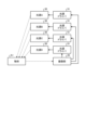
- FIG. 1 is a diagram illustrating a configuration example of an object recognition system according to an embodiment of the present disclosure.
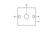
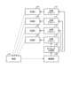
- FIG. 3 is a diagram for explaining a first arrangement example of a plurality of light sources according to an embodiment of the present disclosure.
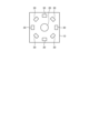
- FIG. 7 is a diagram for explaining a second arrangement example of a plurality of light sources according to an embodiment of the present disclosure.
- FIG. 7 is a diagram for explaining a third arrangement example of a plurality of light sources according to an embodiment of the present disclosure.
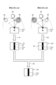
- FIG. 3 is a diagram for explaining generation of a composite image according to an embodiment of the present disclosure.
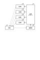
- FIG. 2 is a diagram illustrating a first configuration example regarding light emission control according to an embodiment of the present disclosure.
- FIG. 7 is a diagram illustrating a second configuration example regarding light emission control according to an embodiment of the present disclosure.
- FIG. 7 is a diagram illustrating a third configuration example regarding light emission control according to an embodiment of the present disclosure.
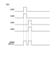
- FIG. 7 is a diagram illustrating a second timing chart example regarding light emission control according to an embodiment of the present disclosure.
- FIG. 7 is a diagram illustrating a fourth configuration example regarding light emission control according to an embodiment of the present disclosure.
- FIG. 7 is a diagram illustrating a third timing chart example regarding light emission control according to an embodiment of the present disclosure.
- FIG. 7 is a diagram illustrating a fourth timing chart example regarding light emission control according to an embodiment of the present disclosure.
- FIG. 2 is a diagram showing an example of a schematic configuration of hardware.
- One or more embodiments (including examples and modifications) described below can each be implemented independently. On the other hand, at least a portion of the plurality of embodiments described below may be implemented in combination with at least a portion of other embodiments as appropriate. These multiple embodiments may include novel features that are different from each other. Therefore, these multiple embodiments may contribute to solving mutually different objectives or problems, and may produce mutually different effects.
- Embodiment 1-1 Configuration example of object recognition system 1-2.
- Fourth processing example 1-5 Action/Effect 2.
- FIG. 1 is a diagram showing a configuration example of an object recognition system 1 according to the present embodiment.
- the object recognition system 1 includes a transport section 10, an imaging section 20, a plurality of light sources 30, a robot 40, and a control section 50.
- the transport unit 10 transports an object A1 such as a box.
- This conveyance section 10 is realized by, for example, a belt conveyor.
- the transport unit 10 is controlled by the control unit 50, for example, but may be controlled by another system such as a transport system.
- boxes may be transported individually or side by side.
- the imaging unit 20 images the object A1 on the transport unit 10.
- This imaging unit 20 is realized, for example, by an image sensor (distance image sensor) that photographs the object A1.
- an image sensor distance image sensor
- an active type image sensor such as an iToF (indirect time of flight) type, dToF (direct time of flight) type, or structured light type image sensor is used.
- the imaging unit 20 is realized by an image sensor capable of acquiring a distance image (depth image having depth information for each pixel) and an infrared image (IR image); It may be realized by two sensors, including an image sensor capable of acquiring an image.
- Each light source 30 irradiates light containing infrared rays (for example, laser light) toward the object A1 on the transport unit 10.
- These light sources 30 are provided around the imaging unit 20 so as not to prevent the imaging unit 20 from imaging the object A1 on the transport unit 10.
- each light source 30 is arranged radially around the imaging unit 20.
- the number of light sources 30 is two or more.
- by changing the light source 30 that emits light it is possible to arbitrarily change the light emitting position and adjust the angle of the light beam irradiated to the object A1, and also the amount of light can be adjusted. It is possible.
- the arrangement of each light source 30 will be described in detail later.
- the robot 40 is a device that lifts the object A1 from the transport section 10 and transports it to another location.
- This robot 40 is realized by, for example, a robot arm.
- the robot 40 is controlled by the control unit 50, but may be controlled by another system such as a transport system.
- the control unit 50 is a control device that controls each unit such as the transport unit 10, the imaging unit 20, and each light source 30.
- the control section 50 includes a light source driver 51, an image processing section 52, and the like.
- the light source driver 51 is provided commonly to each light source 30 and controls the driving (turning on and off) of each light source 30.
- the image processing unit 52 performs various image processing. Examples of this image processing include object recognition processing and composite image generation processing. These object recognition processes and composite image generation processes will be described in detail later.
- the control unit 50 is realized by, for example, a processor such as a CPU (Central Processing Unit) or an MPU (Micro Processing Unit).
- the control unit 50 executes various programs using a RAM (Random Access Memory) or the like as a work area, but it may also be realized by an integrated circuit such as an FPGA (Field Programmable Gate Array) or an ASIC (Application Specific Integrated Circuit).
- FPGA Field Programmable Gate Array
- ASIC Application Specific Integrated Circuit
- CPUs, MPUs, ASICs, and FPGAs can all be considered processors.
- the control unit 50 may be realized by a GPU (Graphics Processing Unit) in addition to or instead of the CPU.
- the control unit 50 may be realized by specific software instead of specific hardware.
- the image processing unit 52 executes, for example, an application that performs object recognition or image generation.
- applications include various applications such as general-purpose applications and dedicated applications.
- the application may be realized by, for example, AI (artificial intelligence).
- AI artificial intelligence
- the application may be executed based on a model trained by a neural network (for example, CNN: convolutional neural network), which is an example of machine learning, or may be executed based on other techniques.
- the features of the object A1 are recognized by image processing.
- the features of the object A1 include, for example, a contour and a non-contour portion (non-contour region).
- the contour also includes, for example, a groove line A1b, which is a gap between the boxes.
- the non-contour portion includes, for example, black tape A1a.
- This black tape A1a has gloss and is attached to the surface of the object A1.
- Features such as the outline of the object A1 (including the groove line A1b) and the black tape A1a are detected, and the object A1 is recognized. Recognizing the object A1 means, for example, understanding the size and shape of the object A1.
- the control unit 50 may be connected to each unit such as the transport unit 10, the imaging unit 20, and each light source 30 via a network.
- the network is, for example, a communication network (communication network) such as a LAN (Local Area Network), a WAN (Wide Area Network), a cellular network, a fixed telephone network, a local IP (Internet Protocol) network, or the Internet.
- the network may include a wired network or a wireless network.
- the network may include a core network.
- the core network is, for example, EPC (Evolved Packet Core) or 5GC (5G Core network).
- the network may include a data network other than the core network.
- the data network may be a carrier's service network, for example an IMS (IP Multimedia Subsystem) network.
- the data network may be a private network such as an in-house network.
- radio access technology LTE (Long Term Evolution), NR (New Radio), Wi-Fi (registered trademark), Bluetooth (registered trademark), etc.
- RAT radio access technology
- LTE and NR are types of cellular communication technologies that enable mobile communication by arranging multiple areas covered by base stations in the form of cells.
- FIGS. 2 to 4 are diagrams for explaining arrangement examples (first to third arrangement examples) of the light sources 30 according to this embodiment.
- one area of the transport section 10, the imaging section 20, and each light source 30 are shown in plan view.
- the number of light sources 30 according to the first arrangement example is two.
- the two light sources 30 are provided so as to face each other with the imaging unit 20 in between in a plan view, for example, to face each other with the imaging unit 20 at the center in a plan view. That is, the two light sources 30 are provided point-symmetrically with respect to the imaging unit 20.
- the two light sources 30 may be arranged in a direction parallel to the transport direction of the object A1 in plan view, or may be arranged in a direction perpendicular to the transport direction of the object A1.
- the number of light sources 30 according to the second arrangement example is four.
- the four light sources 30 are provided radially so as to surround the imaging section 20 in a plan view, for example, to surround the imaging section 20 in a plan view.
- These light sources 30 are arranged, for example, on the same circle centered on the imaging unit 20 at equal intervals.
- the four light sources 30 are each provided so that the two light sources 30 that form a pair in plan view are point symmetrical with respect to the imaging unit 20 . In order to achieve a uniform light amount distribution, it is desirable to use a symmetrical arrangement with the imaging unit 20 at the center in plan view.
- the number of light sources 30 according to the third arrangement example is eight.
- the eight light sources 30 are provided radially so as to surround the imaging unit 20 in a plan view, for example, to surround the imaging unit 20 in a plan view.
- These light sources 30 are arranged, for example, on the same circle centered on the imaging unit 20 at equal intervals.
- the eight light sources 30 are provided so that the two light sources 30 that form a pair in plan view are point symmetrical with respect to the imaging unit 20 .
- the number of light sources 30 to be arranged is large. This is because it is possible to increase the number of light emitting patterns, and it becomes easier to set conditions for suppressing saturation depending on reflected light intensity.
- first arrangement example, second arrangement example, third arrangement example, and the number of light sources 30 as described above are merely examples, and other arrangements and numbers may be adopted.
- the number of light sources 30 may be an even number or an odd number as long as it is two or more.
- the light sources 30 are arranged on the same circle at equal intervals, they do not have to be on the same circle or at equal intervals.
- FIG. 5 is a diagram for explaining an example of generating a composite image according to this embodiment.
- the number of light sources 30 is two (see the above-mentioned first arrangement example: FIG. 2).
- the light emitting pattern A is a pattern in which one of the two light sources 30 emits light
- the light emitting pattern B is a pattern in which the other of the two light sources 30 emits light.
- the light reflected by the glossy black tape A1a becomes stronger.
- one of the light sources 30 is turned on for a certain period of time (for example, several seconds), and both the distance image and the infrared image G1 are acquired by the imaging unit 20 (step S1).
- the black tape A1a in both images G1 includes a saturated region R1 (for example, blown out highlights) that depends on the intensity of reflected light.
- the other light source 30 is turned on for a certain period of time (for example, several seconds), and both the distance image and the infrared image G2 are acquired by the imaging unit 20 (step S2).
- the black tape A1a in both images G2 includes a saturated region R1 (for example, blown-out highlights) that depends on the intensity of reflected light.
- the position of the saturated region R1 according to the light emission pattern B is different from the position of the saturated region R1 according to the light emission pattern A. This is because the light emitting pattern A and the light emitting pattern B have different light sources 30 (light emitting positions) that emit light, and have different angles of light rays irradiated onto the object A1. That is, by changing the light emitting position, it is possible to prevent the saturated region R1 from being at the same position in different images.
- the light emission time (lighting time) during which the light source 30 emits light may be the same or different.
- the light emission time may be intentionally made different.
- the individual lighting timings of each light source 30 are different, the individual lighting timings may be different or the same. However, considering the ease of adjusting the beam angle and light amount, it is desirable to vary the timing of extinguishing the lights.
- Both images G1 based on the light emission pattern A and both images G2 based on the light emission pattern B are superimposed on each other as distance images and infrared images, and a composite image G3, which is a composite image of both, is generated by the image processing unit 52 (step S3 ). That is, a distance image based on emission pattern A and a distance image based on emission pattern B are superimposed to generate a composite distance image, and an infrared image based on emission pattern A and an infrared image based on emission pattern B are superimposed to generate a composite infrared image. .
- the composite range image and composite infrared image are then used for object recognition.
- the black tape A1a black tape area included in both the composite distance image and the composite infrared image does not include a saturated area R1 (for example, blown-out highlights) that depends on the reflected light intensity. That is, the image processing unit 52 superimposes the distance image based on the emission pattern A and the distance image based on the emission pattern B so as to remove the saturated region R1 in the distance image and the infrared image, and the infrared image based on the emission pattern A and the emission pattern By superimposing the infrared image obtained by B, a composite distance image and a composite infrared image are generated.
- the saturated region R1 is eliminated from the composite distance image and the composite infrared image, so features of the object A1 such as a box, such as the black tape A1a and the groove line A1b, can be detected with high accuracy.
- a box such as the black tape A1a and the groove line A1b
- This makes it possible to prevent erroneously detecting the black tape A1a as the groove line A1b and recognizing one box as two boxes.
- an infrared image and a distance image are used, and the saturated region R1 is removed from the infrared image and the distance image by composite image processing, and the object A1 is removed from the composite infrared image and the composite distance image. is recognized.
- the images obtained based on the two light emitting patterns A and B have been described, but the number of images obtained by increasing the number of light emitting patterns may be increased.
- By increasing the number of images it becomes possible to remove the saturated region R1 more reliably, so that the features of the object A1 such as a box, for example, the black tape A1a, can be recognized with higher accuracy.
- FIGS. 6 to 13 A configuration example and a processing example regarding light emission control (lighting and extinguishing) according to this embodiment will be described with reference to FIGS. 6 to 13.
- FIG. 8, FIG. 9, and FIG. 11 are diagrams showing configuration examples (first to fourth configuration examples) regarding light emission control according to the present embodiment.
- FIG. 10, FIG. 12, and FIG. 13 are diagrams showing timing chart examples (first to fourth timing chart examples) regarding light emission control according to the present embodiment.
- the number of light sources 30 is four (see the aforementioned second arrangement example: FIG. 3), and the number of light source drivers 51 is one.
- light source A, light source B, light source C, and light source D are shown as four light sources 30.
- the light source driver 51 is provided in common to the four light sources 30.
- the light source driver 51 turns on at least one of the light sources 30 for a certain period of time based on the synchronization timing issued from the imaging section 20.
- light emission pulses are input to light source A, light source B, light source C, and light source D (four light sources 30) at different timings.
- the light emission pulse is input to each of the light sources A, B, C, and D in this order in synchronization with the read pulse from the imaging unit 20.
- this light emitting pulse becomes a high level (amplitude 1)
- each light source A, B, C , D are in the OFF state (light out state).
- the imaging unit 20 issues read pulses, that is, synchronization timing (read timing) at predetermined intervals.
- the light source driver 51 controls the light emission timing (lighting timing) and extinguishing timing of each of the light sources A, B, C, and D based on the synchronization timing issued from the imaging unit 20. For example, the light source driver 51 repeatedly turns on and off (lights light for a certain period of time) light source A, light source B, light source C, and light source D in the order based on the synchronization timing issued from the imaging unit 20.
- a simple configuration regarding light emission control can be realized.
- object recognition accuracy can be improved with a simple configuration.
- light source A, light source B, light source C, and light source D are shown as the four light sources 30, as in the other figures.
- a light source driver 51 is provided for each light source 30.
- Each of these light source drivers 51 turns on and off the corresponding light source 30 based on the synchronization timing issued from the imaging unit 20. Note that the imaging unit 20 controls the synchronization timing (readout timing) issued to each light source driver 51, respectively.
- the number of light sources 30 is four (see the aforementioned second arrangement example: FIG. 3), and the number of light source drivers 51 is four.
- light source A, light source B, light source C, and light source D are shown as the four light sources 30, as in the other figures.
- a light source driver 51 is provided for each light source 30.
- a timing distribution section 53 is present. This timing distribution section 53 is realized by, for example, a timing distribution circuit, and is included in the control section 50.
- the timing distribution unit 53 issues light emission timing (lighting timing) and light extinguishing timing to each light source driver 51 based on the synchronization timing issued from the imaging unit 20.
- Each of these light source drivers 51 turns on and off the corresponding light source 30 (light emission for a certain period of time) based on the light emission timing and light extinction timing issued from the timing distribution unit 53.
- the imaging unit 20 controls the synchronization timing (read timing) issued to the timing distribution unit 53.
- light emission pulses are input to light source A, light source B, light source C, and light source D (four light sources 30) at different timings.
- the light emission pulse is input to each of the light sources A, B, C, and D in this order in synchronization with the readout pulse from the imaging unit 20.
- this light emission pulse becomes a high level (amplitude 1)
- each light source A, B, C, and D becomes an ON state
- when it becomes a low level (amplitude 0) each light source A, B, C, and D becomes an OFF state.
- the imaging unit 20 issues read pulses, that is, synchronization timing (read timing) at predetermined intervals.
- the timing distribution unit 53 issues light emission timing (lighting timing) and light extinguishing timing to each light source driver 51 based on the synchronization timing issued from the imaging unit 20.
- the light source driver 51 controls the individual light emission timing and light extinction timing of each of the light sources A, B, C, and D based on the light emission timing and light extinction timing issued from the timing distributor 53. For example, the light source driver 51 repeats turning on and off the light source A, the light source B, the light source C, and the light source D in the order based on the light emission timing and the light extinction timing issued from the timing distribution unit 53 (light emission for a certain period of time).
- each light source 30 can emit light at different timings. Recognition accuracy can be improved.
- the number of light sources 30 is four (see the aforementioned second arrangement example: FIG. 3), and the number of light source drivers 51 is four.
- light source A, light source B, light source C, and light source D are shown as four light sources 30, as in the other figures.
- a light source driver 51 is provided for each light source 30.
- a synchronization control section 54 is present.
- the synchronization control section 54 is realized by, for example, a synchronization control circuit (for example, an FPGA, a microcomputer, etc.), and is included in the control section 50.
- the synchronization control unit 54 issues a read timing to the imaging unit 20, and also issues light emission timing (lighting timing) and light extinguishing timing to each light source driver 51 in synchronization with the read timing.
- Each of the light source drivers 51 turns on and off the corresponding light source 30 (light emission for a certain period of time) based on the light emission timing and light extinction timing issued from the synchronous control unit 54, and also causes the corresponding light source 30 to turn on and off (light emission for a certain period of time).
- the image is read out based on the readout timing.
- each light source 30 can emit light at different timings while being synchronized with the readout timing. Therefore, object recognition accuracy can be improved. Furthermore, it becomes possible to use various types of imaging sections 20, and it becomes easy to replace the imaging section 20.
- the timing chart according to the third processing example is a timing chart when the imaging unit 20 is iToF.
- the timing chart according to the third processing example is the same as the timing chart according to the first processing example (see FIG. 7), but the actual light emission pulse and the readout pulse of the imaging unit 20 are short-cycle pulses.
- the imaging unit 20 is iToF, the light emission is in the form of short pulses, and a plurality of variations (for example, four phases) in the phase relationship between light emission and imaging are required.
- four phases (0deg, 90deg, 180deg, 270deg) are read out by multiple taps (a tap, b tap) of the imaging unit 20.
- a tap, b tap the example in which 4 phases are read out with each tap (a tap, b tap)
- similar readout is performed in other variations (for example, 2 phases, 8 phases, etc.). .
- light source A and light source B emit light at the same time
- light source C and light source D emit light at the same time
- the light source driver 51 turns on and off at least two of the light sources A, B, C, and D simultaneously based on the synchronization timing issued from the imaging unit 20 (light emission for a certain period of time).
- the plurality of light sources 30 emit light at the same time, so that the time required for all frames to be aligned can be shortened. Furthermore, since it becomes possible to increase the amount of light, distance measurement performance can be improved.
- the light source A and the light source B are turned on (light-emitting light) at the same time, and the light source C and the light source D are turned on (light-emitting light) at the same time, but the light source A and the light source Two light sources C may be turned on at the same time, two light sources A and D may be turned on at the same time, or three light sources A, B, and C may be turned on at the same time.
- the number of light sources 30 is four, but the number is not particularly limited as long as it is two or more. Moreover, the number of light sources 30 to be turned on at the same time is not particularly limited, as long as it is two or more. Furthermore, various combinations of the number of light sources 30 to be turned on simultaneously are possible, for example, first the number of light sources 30 to be turned on at the same time is two, and then the number of light sources 30 to be turned on at the same time is three. be.
- the object recognition system 1 includes a plurality of light sources 30 that irradiate the object A1 with light including infrared rays, and a control unit that turns on the plurality of light sources 30 at different timings. 50, and an imaging unit 20 that acquires a distance image and an infrared image of the object A1 at each timing, and the control unit 50 acquires a range image at each timing (for example, one of both images G1 and one of both images G2).
- a composite distance image for example, one of both composite images G3
- infrared images for each timing for example, the other of both images G1 and the other of both images G2 are superimposed to generate a composite infrared image (for example, , the other of both composite images G3)
- a composite infrared image for example, , the other of both composite images G3
- the saturated region R1 is eliminated from the composite distance image and the composite infrared image, and the object A1 can be recognized with high accuracy, so that the object recognition accuracy can be improved.
- the control unit 50 also superimposes the distance images for each timing and superimposes the infrared images for each timing so as to remove the saturated region R1 that depends on the intensity of reflected light in the distance images and infrared images for each timing. Then, a composite distance image and a composite infrared image may be generated. This makes it possible to reliably eliminate the saturated region R1 from the composite distance image and the composite infrared image, thereby reliably improving object recognition accuracy.
- control unit 50 may turn off each light source 30 at different timings. Thereby, by controlling both the timing of turning on and turning off the lights, it is possible to reliably eliminate the saturated region R1 from the composite distance image and the composite infrared image, so that object recognition accuracy can be reliably improved.
- each light source 30 may be provided with the imaging unit 20 at the center in plan view (see FIGS. 2 to 4). This makes it possible to obtain distance images and infrared images with different beam angles of irradiation light, thereby reliably improving object recognition accuracy.
- each light source 30 may be provided so as to face each other with the imaging unit 20 in between in plan view (see FIGS. 2 to 4). This makes it possible to obtain distance images and infrared images with different beam angles of irradiation light, thereby reliably improving object recognition accuracy.
- each light source 30 may be provided so as to surround the imaging unit 20 in plan view (see FIGS. 3 and 4). This makes it possible to obtain distance images and infrared images with different beam angles of irradiation light, thereby reliably improving object recognition accuracy.
- each light source 30 may be provided point-symmetrically with respect to the imaging unit 20 in plan view (see FIGS. 2 to 4). This makes it possible to obtain distance images and infrared images with different ray angles of irradiation light, and also to realize a uniform light amount distribution, so that object recognition accuracy can be reliably improved.
- control unit 50 has a common light source driver 51 for each light source 30, and the light source driver 51 may turn on at least one of the light sources 30 based on the synchronization timing issued from the imaging unit 20. Good (see Figure 6). This makes it possible to implement control with a simple configuration, so that object recognition accuracy can be improved with a simple configuration.
- control unit 50 may include a light source driver 51 for each light source 30, and each of the light source drivers 51 for each light source 30 may turn on the light source 30 based on the synchronization timing issued from the imaging unit 20 ( (See Figure 8). Accordingly, since the light source driver 51 is provided for each light source 30, detailed control of each light source 30 is possible, so that object recognition accuracy can be reliably improved.
- control unit 50 includes a timing distribution unit 53, and the timing distribution unit 53 issues light emission timing (lighting timing) to the light source driver 51 of each light source 30 based on the synchronization timing issued from the imaging unit 20.
- each of the light source drivers 51 for each light source 30 may turn on the light source 30 based on the light emission timing issued from the timing distribution unit 53 (see FIG. 9).
- control unit 50 has a light source driver 51 and a synchronization control unit 54 for each light source 30, and the synchronization control unit 54 issues a readout timing to the imaging unit 20, and synchronizes the readout timing with the readout timing for each light source 30.
- a light emission timing (lighting timing) is issued to the light source driver 51, each of the light source drivers 51 for each light source 30 lights up the light source 30 based on the light emission timing issued from the synchronization control section 54, and the imaging section 20 performs synchronization.
- the distance image and the infrared image may be acquired based on the readout timing issued by the control unit 54 (see FIG. 11).
- the imaging unit 20 may be an iToF (indirect time of flight) image sensor (see FIG. 12). This makes it possible to obtain accurate distance images, thereby reliably improving object recognition accuracy.
- iToF indirect time of flight
- control unit 50 may turn on some of the light sources 30 at the same timing (see FIG. 13). This makes it possible to adjust the amount of light, thereby reliably improving object recognition accuracy.
- the object A1 may be a box, and the features of the box may include a contour and a non-contour part. Object recognition accuracy can be improved for such object A1.
- the contour may include the groove line A1b, and the non-contour portion may include the black tape A1a. Object recognition accuracy can be improved for such object A1.
- non-contour portion may include a sticker in addition to the black tape A1a. Object recognition accuracy can be improved for such object A1.
- FIG. 14 is a diagram illustrating an example of a schematic configuration of hardware that implements the functions of an information device.
- the computer 500 includes a CPU 510, a RAM 520, a ROM (Read Only Memory) 530, an HDD (Hard Disk Drive) 540, a communication interface 550, and an input/output interface 560. Each part of computer 500 is connected by a bus 570.
- the CPU 510 operates based on a program stored in the ROM 530 or HDD 540 and controls each part. For example, the CPU 510 loads programs stored in the ROM 530 or HDD 540 into the RAM 520, and executes processes corresponding to various programs.
- the ROM 530 stores boot programs such as BIOS (Basic Input Output System) that are executed by the CPU 510 when the computer 500 is started, programs that depend on the hardware of the computer 500, and the like.
- BIOS Basic Input Output System
- the HDD 540 is a recording medium readable by the computer 500 that non-temporarily records programs executed by the CPU 510 and data used by the programs. Specifically, the HDD 540 is a recording medium that records program data 541.
- the communication interface 550 is an interface for connecting the computer 500 to an external network 580 (the Internet as an example).
- the CPU 510 receives data from other devices or transmits data generated by the CPU 510 to other devices via the communication interface 550.
- the input/output interface 560 is an interface for connecting the input/output device 590 and the computer 500.
- CPU 510 receives data from an input device such as a keyboard or mouse via input/output interface 560. Further, the CPU 510 transmits data to an output device such as a display, speaker, or printer via the input/output interface 560.
- the input/output interface 560 may function as a media interface that reads a program recorded on a predetermined recording medium (media).
- media include optical recording media such as DVD (Digital Versatile Disc) and PD (Phase change rewritable disk), magneto-optical recording media such as MO (Magneto-Optical disk), tape media, magnetic recording media, or semiconductors. Memory etc. are used.
- the CPU 510 of the computer 500 functions as a part of the object recognition system 1 or an information device such as the control unit 50 according to each embodiment (or modification)
- the CPU 510 of the computer 500 functions as a By executing the information processing program, all or part of the functions of each section according to each embodiment (or modification) are realized.
- the HDD 540 stores information processing programs and data according to each embodiment.
- the CPU 510 reads the program data 541 from the HDD 540 and executes it, as another example, these programs may be acquired from another device via the external network 580.
- each component of each device shown in the drawings is functionally conceptual, and does not necessarily need to be physically configured as shown in the drawings.
- the specific form of distributing and integrating each device is not limited to what is shown in the diagram, and all or part of the devices can be functionally or physically distributed or integrated in arbitrary units depending on various loads and usage conditions. Can be integrated and configured.
- the present technology can also have the following configuration.
- the control unit superimposes the distance images for each timing and superimposes the infrared images for each timing so as to remove a saturated region that depends on the intensity of reflected light in the distance images and infrared images for each timing, generating the composite range image and the composite infrared image;
- the control unit turns off the plurality of light sources at different timings, respectively.
- the plurality of light sources are provided around the imaging unit in plan view, The object recognition system according to any one of (1) to (3) above.
- the plurality of light sources are provided so as to face each other with the imaging unit in between in plan view.
- the plurality of light sources are provided so as to surround the imaging unit in a plan view, The object recognition system according to any one of (1) to (5) above.
- the plurality of light sources are provided so as to be point symmetrical with respect to the imaging unit in a plan view, The object recognition system according to any one of (1) to (6) above.
- the control unit has a light source driver common to the plurality of light sources, The light source driver turns on at least one of the plurality of light sources based on synchronization timing issued from the imaging unit.
- the object recognition system according to any one of (1) to (7) above.
- the control unit has a light source driver for each of the light sources, Each of the light source drivers for each light source turns on the light source based on synchronization timing issued from the imaging unit.
- the object recognition system according to any one of (1) to (7) above.
- the control unit includes a timing distribution unit, The timing distribution unit issues light emission timing to the light source driver for each light source based on the synchronization timing issued from the imaging unit, Each of the light source drivers for each light source lights up the light source based on the light emission timing issued from the timing distribution unit.
- the object recognition system according to (9) above.
- the control unit includes a light source driver and a synchronization control unit for each of the light sources,
- the synchronization control unit issues readout timing to the imaging unit, and issues light emission timing to the light source driver for each light source in synchronization with the readout timing,
- Each of the light source drivers for each light source lights up the light source based on the light emission timing issued from the synchronization control unit,
- the imaging unit acquires the distance image and the infrared image based on the readout timing issued from the synchronization control unit.
- the object recognition system according to any one of (1) to (7) above.
- the imaging unit is an iToF (indirect time of flight) image sensor, The object recognition system according to any one of (1) to (11) above.
- the control unit turns on some light sources among the plurality of light sources at the same timing.
- the object is a box;
- the box features include contours and non-contours;
- the contour includes a groove line;
- the non-contour portion includes black tape;
- the non-contour portion includes a seal in addition to the black tape, The object recognition system according to (15) above.
- a plurality of light sources that irradiate an object with light including infrared radiation; a control unit that turns on each of the plurality of light sources at different timings; an imaging unit that acquires a distance image and an infrared image of the object at each timing; Equipped with The control unit generates a composite distance image by overlapping the distance images for each of the timings, generates a composite infrared image by overlapping the infrared images for each of the timings, and generates a composite infrared image based on the composite distance image and the composite infrared image. recognizing the object by Object recognition device.
- the object recognition system Turning on multiple light sources that irradiate an object with light including infrared rays at different times, acquiring a distance image and an infrared image of the object at each of the timings; Generating a composite distance image by overlapping the distance images for each timing, generating a composite infrared image by overlapping the infrared images for each timing, and recognizing the object based on the composite distance image and the composite infrared image. to do and Object recognition methods, including: (19) An object recognition device having the configuration according to the object recognition system according to any one of (1) to (16) above. (20) An object recognition method, wherein the object recognition system according to any one of (1) to (16) above recognizes an object.
- Object recognition system 10 Transport unit 20 Imaging unit 30 Light source 40 Robot 50 Control unit 51 Light source driver 52 Image processing unit 53 Timing distribution unit 54 Synchronization control unit A1 Object A1a Black tape A1b Groove line G1 Both images G2 Both images G3 Both composite images R1 saturation region
Landscapes
- Physics & Mathematics (AREA)
- General Physics & Mathematics (AREA)
- Electromagnetism (AREA)
- Engineering & Computer Science (AREA)
- Radar, Positioning & Navigation (AREA)
- Remote Sensing (AREA)
- Computer Networks & Wireless Communication (AREA)
- Length Measuring Devices By Optical Means (AREA)
Abstract
本開示の一形態に係る物体認識システムは、物体に対して赤外線を含む光を照射する複数の光源と、前記複数の光源をそれぞれ異なるタイミングで点灯させる制御部と、前記タイミングごとの前記物体の距離画像及び赤外線画像を取得する撮像部と、を備え、前記制御部は、前記タイミングごとの距離画像を重ね合わせて合成距離画像を生成し、前記タイミングごとの赤外線画像を重ね合わせて合成赤外線画像を生成し、前記合成距離画像及び前記合成赤外線画像に基づいて前記物体を認識する。
Description
本開示は、物体認識システム、物体認識装置及び物体認識方法に関する。
例えば、物流倉庫や製造工場などにおいて、物体の一例である箱がベルトコンベアによって搬送されたり、また、ロボットアームなどのロボットによりベルトコンベアから持ち上げられて運搬されたりする。このとき、複数の箱は並んで搬送されることがあり、また、複数の箱がパレットに積載され、そのパレットごと搬送されることもある。
このような搬送を実現する搬送システムは、サイズによる箱の搬送経路の切り替えやロボットによる持ち上げなどのため、箱を認識し、搬送経路の切り替え装置やロボットなどを制御する必要がある。このため、複数の箱が並んで搬送されても、それらの箱の隙間(溝線)を検出したり、箱の輪郭(エッジ)を検出したりして、箱のサイズや形状などを認識する。
具体的には、箱のサイズや形状などを認識するため、ベルトコンベア(背景)と箱(前景)の色の違いから箱群の外形を検出し、暗い直線部分を箱の切れ目(溝線)として輪郭を検出し、その輪郭で囲まれた部分を一つの箱と認識する技術が提案されている(例えば、特許文献1参照)。また、平行な一対のエッジ(輪郭)を手がかりに、交差するエッジ対同士を組合せて物体エッジセットを生成し、その物体エッジセットで囲まれた部分を一つの箱と認識する技術も提案されている(例えば、特許文献2参照)。
しかしながら、前述の技術では、箱に貼られた黒テープやシールなどの特徴を輪郭(エッジ)として検出することがあるため、例えば、一つの箱を二つの箱として認識することがあり、箱などの物体を精度よく認識することは困難である。また、箱に貼られた光沢のある黒テープやシールなどの特徴部分の反射光は強く、その部分が画像において飽和領域となるため、特徴部分を検出することが難しく、箱などの物体を精度よく認識することは困難である。
そこで、本開示では、物体認識精度を向上させることを可能にする物体認識システム、物体認識装置及び物体認識方法を提供する。
本開示の一形態に係る物体認識システムは、物体に対して赤外線を含む光を照射する複数の光源と、前記複数の光源をそれぞれ異なるタイミングで点灯させる制御部と、前記タイミングごとの前記物体の距離画像及び赤外線画像を取得する撮像部と、を備え、前記制御部は、前記タイミングごとの距離画像を重ね合わせて合成距離画像を生成し、前記タイミングごとの赤外線画像を重ね合わせて合成赤外線画像を生成し、前記合成距離画像及び前記合成赤外線画像に基づいて前記物体を認識する。
本開示の一形態に係る物体認識装置は、物体に対して赤外線を含む光を照射する複数の光源と、前記複数の光源をそれぞれ異なるタイミングで点灯させる制御部と、前記タイミングごとの前記物体の距離画像及び赤外線画像を取得する撮像部と、を備え、前記制御部は、前記タイミングごとの距離画像を重ね合わせて合成距離画像を生成し、前記タイミングごとの赤外線画像を重ね合わせて合成赤外線画像を生成し、前記合成距離画像及び前記合成赤外線画像に基づいて前記物体を認識する。
本開示の一形態に係る物体認識方法は、物体認識システムが、物体に対して赤外線を含む光を照射する複数の光源をそれぞれ異なるタイミングで点灯させることと、前記タイミングごとの前記物体の距離画像及び赤外線画像を取得することと、前記タイミングごとの距離画像を重ね合わせて合成距離画像を生成し、前記タイミングごとの赤外線画像を重ね合わせて合成赤外線画像を生成し、前記合成距離画像及び前記合成赤外線画像に基づいて前記物体を認識することと、を含む。
以下に、本開示の実施形態について図面に基づいて詳細に説明する。なお、この実施形態により本開示に係るシステムや装置、方法などが限定されるものではない。また、以下の各実施形態において、基本的に同一の部位には同一の符号を付することにより重複する説明を省略する。
以下に説明される1又は複数の実施形態(実施例、変形例を含む)は、各々が独立に実施されることが可能である。一方で、以下に説明される複数の実施形態は少なくとも一部が他の実施形態の少なくとも一部と適宜組み合わせて実施されてもよい。これら複数の実施形態は、互いに異なる新規な特徴を含み得る。したがって、これら複数の実施形態は、互いに異なる目的又は課題を解決することに寄与し得、互いに異なる効果を奏し得る。
以下に示す項目順序に従って本開示を説明する。
1.実施形態
1-1.物体認識システムの構成例
1-2.複数の光源の配置例
1-2-1.第1配置例
1-2-2.第2配置例
1-2-3.第3配置例
1-3.合成画像の生成例
1-4.発光制御に関する構成例及び処理例
1-4-1.第1構成例及び第1処理例
1-4-2.第2構成例
1-4-3.第3構成例及び第2処理例
1-4-4.第4構成例
1-4-5.第3処理例
1-4-6.第4処理例
1-5.作用・効果
2.ハードウェアの構成例
3.他の実施形態
4.付記
1.実施形態
1-1.物体認識システムの構成例
1-2.複数の光源の配置例
1-2-1.第1配置例
1-2-2.第2配置例
1-2-3.第3配置例
1-3.合成画像の生成例
1-4.発光制御に関する構成例及び処理例
1-4-1.第1構成例及び第1処理例
1-4-2.第2構成例
1-4-3.第3構成例及び第2処理例
1-4-4.第4構成例
1-4-5.第3処理例
1-4-6.第4処理例
1-5.作用・効果
2.ハードウェアの構成例
3.他の実施形態
4.付記
<1.実施形態>
<1-1.物体認識システムの構成例>
本実施形態に係る物体認識システム1の構成例について図1を参照して説明する。図1は、本実施形態に係る物体認識システム1の構成例を示す図である。
<1-1.物体認識システムの構成例>
本実施形態に係る物体認識システム1の構成例について図1を参照して説明する。図1は、本実施形態に係る物体認識システム1の構成例を示す図である。
図1に示すように、本実施形態に係る物体認識システム1は、搬送部10と、撮像部20と、複数の光源30と、ロボット40と、制御部50とを備える。
搬送部10は、箱などの物体A1を搬送する。この搬送部10は、例えば、ベルトコンベアにより実現される。搬送部10は、例えば、制御部50により制御されるが、搬送システムなどの他のシステムにより制御されてもよい。例えば、箱は単独で搬送されたり、並んで搬送されたりする。
撮像部20は、搬送部10上の物体A1を撮像する。この撮像部20は、例えば、物体A1を撮影する画像センサ(距離画像センサ)により実現される。画像センサとしては、例えば、iToF(indirect Time of Flight)方式、dToF(direct Time of Flight)方式、又は、構造化照明方式(Structured Light)方式の画像センサなど、アクティブ方式の画像センサが用いられる。なお、撮像部20は、距離画像(画素ごとに奥行き情報を有するデプス画像)及び赤外線画像(IR画像)を取得可能な画像センサにより実現されるが、距離画像を取得可能な画像センサと、赤外線画像を取得可能な画像センサとの二つのセンサにより実現されてもよい。
各光源30は、搬送部10上の物体A1に向けて、赤外線を含む光(例えば、レーザ光)を照射する。これらの光源30は、撮像部20が搬送部10上の物体A1を撮像することを妨げないように撮像部20の周囲に設けられている。各光源30は、例えば、撮像部20を中心にして放射状に配置される。光源30の数は二個以上である。このような各光源30の中で、発光させる光源30を変えることで、発光位置を任意に変えて物体A1に照射する光線角度を調整することが可能であり、また、光量を調整することが可能である。このような各光源30の配置について詳しくは後述する。
ロボット40は、搬送部10上から物体A1を持ち上げて他の場所に運搬する装置である。このロボット40は、例えば、ロボットアームにより実現される。例えば、ロボット40は、制御部50によって制御されるが、搬送システムなどの他のシステムにより制御されてもよい。
制御部50は、搬送部10や撮像部20、各光源30などの各部を制御する制御装置である。この制御部50は、光源ドライバ51や画像処理部52などを備える。光源ドライバ51は、各光源30に共通に設けられており、各光源30のそれぞれの駆動(点灯及び消灯)を制御する。画像処理部52は、各種の画像処理を実行する。この画像処理としては、例えば、物体認識処理や合成画像生成処理などがある。これらの物体認識処理や合成画像生成処理について詳しくは後述する。
この制御部50は、例えば、CPU(Central Processing Unit)やMPU(Micro Processing Unit)などのプロセッサにより実現される。例えば、制御部50は、RAM(Random Access Memory)などを作業領域として各種プログラムを実行するが、FPGA(Field Programmable Gate Array)又はASIC(Application Specific Integrated Circuit)などの集積回路により実現されてもよい。CPU、MPU、ASIC及びFPGAは、いずれもプロセッサとみなすことができる。また、制御部50は、CPUに加えてあるいは替えてGPU(Graphics Processing Unit)により実現されてもよい。また、制御部50は、特定のハードウェアではなく、特定のソフトウェアにより実現されてもよい。
また、画像処理部52は、例えば、物体認識や画像生成を行うアプリケーションを実行する。アプリケーションとしては、例えば、汎用アプリケーションや専用アプリケーションなどの各種アプリケーションがある。また、アプリケーションは、例えば、AI(人工知能)により実現されてもよい。例えば、アプリケーションは、機械学習の一例であるニューラルネットワーク(例えば、CNN:畳み込みニューラルネットワークなど)による学習済みモデルに基づいて実行されてもよく、また、他の手法に基づいて実行されてもよい。
ここで、物体認識処理では、物体A1の特徴が画像処理により認識される。物体A1の特徴は、例えば、輪郭及び非輪郭部(非輪郭領域)を含む。輪郭は、例えば、箱の隙間である溝線A1bも含む。非輪郭部は、例えば、黒テープA1aを含む。この黒テープA1aは、光沢を有しており、物体A1の表面に貼られている。なお、物体A1の表面に貼られる部材としては、黒テープA1a以外にも、光沢を有するシールなどがある。このような物体A1の輪郭(溝線A1bも含む)や黒テープA1aなどの特徴が検出され、物体A1が認識される。物体A1の認識とは、例えば、物体A1のサイズや形状などを把握することである。
なお、制御部50は、搬送部10や撮像部20、各光源30などの各部とネットワークを介して接続されてもよい。ネットワークは、例えば、LAN(Local Area Network)、WAN(Wide Area Network)、セルラーネットワーク、固定電話網、地域IP(Internet Protocol)網、インターネットなどの通信ネットワーク(通信網)である。ネットワークには、有線ネットワークが含まれていてもよいし、無線ネットワークが含まれていてもよい。また、ネットワークには、コアネットワークが含まれていてもよい。コアネットワークは、例えば、EPC(Evolved Packet Core)や5GC(5G Core network)である。また、ネットワークには、コアネットワーク以外のデータネットワークが含まれていてもよい。例えば、データネットワークは、通信事業者のサービスネットワーク、例えば、IMS(IP Multimedia Subsystem)ネットワークであってもよい。また、データネットワークは、企業内ネットワークなど、プライベートなネットワークであってもよい。
また、無線アクセス技術(RAT:Radio Access Technology)としては、LTE(Long Term Evolution)、NR(New Radio)、Wi-Fi(登録商標)、Bluetooth(登録商標)などを用いることが可能である。これら数種類の無線アクセス技術を用いてもよく、例えば、NRとWi-Fiを用いてもよく、また、LTEとNRを用いてもよい。LTE及びNRは、セルラー通信技術の一種であり、基地局がカバーするエリアをセル状に複数配置することで、移動通信を可能にする。
<1-2.複数の光源の配置例>
本実施形態に係る複数の光源30の配置例について図2から図4を参照して説明する。図2から図4は、本実施形態に係る光源30の配置例(第1から第3配置例)を説明するための図である。図2から図4の例では、平面視で搬送部10の一領域、撮像部20及び各光源30が示されている。
本実施形態に係る複数の光源30の配置例について図2から図4を参照して説明する。図2から図4は、本実施形態に係る光源30の配置例(第1から第3配置例)を説明するための図である。図2から図4の例では、平面視で搬送部10の一領域、撮像部20及び各光源30が示されている。
<1-2-1.第1配置例>
図2に示すように、第1配置例に係る光源30の数は二つである。二つの光源30は、平面視で撮像部20を間にして対向するよう、例えば、平面視で撮像部20を中心にして対向するように設けられている。すなわち、二つの光源30は、撮像部20を中心にして点対称になるように設けられている。なお、二つの光源30は、平面視で物体A1の搬送方向に対して平行な方向に並べられても、あるいは、直交な方向に並べられてもよい。
図2に示すように、第1配置例に係る光源30の数は二つである。二つの光源30は、平面視で撮像部20を間にして対向するよう、例えば、平面視で撮像部20を中心にして対向するように設けられている。すなわち、二つの光源30は、撮像部20を中心にして点対称になるように設けられている。なお、二つの光源30は、平面視で物体A1の搬送方向に対して平行な方向に並べられても、あるいは、直交な方向に並べられてもよい。
<1-2-2.第2配置例>
図3に示すように、第2配置例に係る光源30の数は四つである。四つの光源30は、平面視で撮像部20を囲むよう、例えば、平面視で撮像部20を中心にして囲むように放射状に設けられている。これらの光源30は、例えば、撮像部20を中心とする同一円上に等間隔で配置されている。なお、四つの光源30は、平面視で対となる二つの光源30が撮像部20を中心にして点対称になるよう、それぞれ設けられている。均一な光量分布を実現するためには、平面視で撮像部20を中心にした対称的な配置を用いることが望ましい。
図3に示すように、第2配置例に係る光源30の数は四つである。四つの光源30は、平面視で撮像部20を囲むよう、例えば、平面視で撮像部20を中心にして囲むように放射状に設けられている。これらの光源30は、例えば、撮像部20を中心とする同一円上に等間隔で配置されている。なお、四つの光源30は、平面視で対となる二つの光源30が撮像部20を中心にして点対称になるよう、それぞれ設けられている。均一な光量分布を実現するためには、平面視で撮像部20を中心にした対称的な配置を用いることが望ましい。
<1-2-3.第3配置例>
図4に示すように、第3配置例に係る光源30の数は八つである。八つの光源30は、第2配置例と同様、平面視で撮像部20を囲むよう、例えば、平面視で撮像部20を中心にして囲むように放射状に設けられている。これらの光源30は、例えば、撮像部20を中心とする同一円上に等間隔で配置されている。なお、八つの光源30は、平面視で対となる二つの光源30が撮像部20を中心にして点対称になるよう、それぞれ設けられている。均一な光量分布を実現するためには、平面視で撮像部20を中心にした対称的な配置を用いることが望ましい。また、配置する光源30の数は多い方が望ましい。これは、発光パターンのパターン数を増やすことが可能であり、反射光強度に依存する飽和を抑える条件を設定しやすくなるためである。
図4に示すように、第3配置例に係る光源30の数は八つである。八つの光源30は、第2配置例と同様、平面視で撮像部20を囲むよう、例えば、平面視で撮像部20を中心にして囲むように放射状に設けられている。これらの光源30は、例えば、撮像部20を中心とする同一円上に等間隔で配置されている。なお、八つの光源30は、平面視で対となる二つの光源30が撮像部20を中心にして点対称になるよう、それぞれ設けられている。均一な光量分布を実現するためには、平面視で撮像部20を中心にした対称的な配置を用いることが望ましい。また、配置する光源30の数は多い方が望ましい。これは、発光パターンのパターン数を増やすことが可能であり、反射光強度に依存する飽和を抑える条件を設定しやすくなるためである。
なお、前述のような第1配置例、第2配置例、第3配置例、また、光源30の数は、あくまでも例示であり、他の配置や個数が採用されてもよい。光源30の数は、二つ以上であれば、偶数でも奇数でもよい。また、各光源30の配置も、同一円上に等間隔で配置されているが、同一円上でなくてもよく、また、等間隔でなくてもよい。ただし、均一な光量分布を実現するためには、第1配置例や第2配置例、第3配置例などの配置を採用することが望ましい。
<1-3.合成画像の生成例>
本実施形態に係る合成画像の生成例(画像生成処理)について図5を参照して説明する。図5は、本実施形態に係る合成画像の生成例を説明するための図である。図5の例では、光源30の数が二つである(前述の第1配置例:図2参照)。
本実施形態に係る合成画像の生成例(画像生成処理)について図5を参照して説明する。図5は、本実施形態に係る合成画像の生成例を説明するための図である。図5の例では、光源30の数が二つである(前述の第1配置例:図2参照)。
図5に示すように、発光パターンAは二つの光源30の一方が発光するパターンであり、発光パターンBは二つの光源30の他方が発光するパターンである。どちらの発光パターンA、Bでも、光沢のある黒テープA1aによる反射光は強くなる。
発光パターンAによれば、一方の光源30が一定時間(例えば、数秒)点灯し、距離画像及び赤外線画像の両画像G1が撮像部20により取得される(ステップS1)。この両画像G1内の黒テープA1aは、反射光強度に依存する飽和領域R1(例えば、白飛び)を含んでいる。
発光パターンBによれば、他方の光源30が一定時間(例えば、数秒)点灯し、距離画像及び赤外線画像の両画像G2が撮像部20により取得される(ステップS2)。この両画像G2内の黒テープA1aは、反射光強度に依存する飽和領域R1(例えば、白飛び)を含んでいる。
なお、発光パターンBによる飽和領域R1の位置は、発光パターンAによる飽和領域R1の位置と異なる。これは、発光パターンAと発光パターンBとでは、発光する光源30(発光位置)が異なり、物体A1に照射する光線角度が異なるためである。つまり、発光位置を変えることで、異なる画像において飽和領域R1が同じ位置となることを抑えることができる。
また、発光パターンA及び発光パターンBにおいて、光源30が発光する発光時間(点灯時間)は同じであっても、異なっていてもよい。光源30の設置環境によっては、あえて発光時間を異ならせてもよい。また、各光源30の個々の点灯タイミングは異なっているが、個々の消灯タイミングは異なっていても、同じであってもよい。ただし、光線角度や光量の調整の容易さを考慮すると、消灯タイミングも異ならせることが望ましい。
発光パターンAによる両画像G1及び発光パターンBによる両画像G2は、距離画像同士、赤外線画像同士で重ね合わされ、両方の合成画像である両合成画像G3が画像処理部52により生成される(ステップS3)。つまり、発光パターンAによる距離画像と発光パターンBによる距離画像が重ね合わされて合成距離画像が生成され、発光パターンAによる赤外線画像と発光パターンBによる赤外線画像が重ね合わされて合成赤外線画像が生成される。
その後、合成距離画像及び合成赤外線画像が物体認識に用いられる。合成距離画像及び合成赤外線画像の両方に含まれる黒テープA1a(黒テープ領域)は、反射光強度に依存する飽和領域R1(例えば、白飛び)を含んでいない。つまり、画像処理部52は、距離画像及び赤外線画像内の飽和領域R1を取り除くように、発光パターンAによる距離画像と発光パターンBによる距離画像とを重ね合わせ、発光パターンAによる赤外線画像と発光パターンBによる赤外線画像とを重ね合わせることで、合成距離画像及び合成赤外線画像を生成する。
これにより、合成距離画像及び合成赤外線画像には飽和領域R1が無くなるので、箱などの物体A1の特徴、例えば、黒テープA1aや溝線A1bなどを精度よく検出することができる。例えば、合成距離画像に含まれる距離情報(奥行き情報)から、黒テープA1aと溝線A1bとの識別を正確に行うことが可能になるので、箱などの物体A1を精度よく認識することができる。これにより、黒テープA1aを溝線A1bと誤検出して一つの箱を二つの箱として認識してしまうことを抑えることが可能になる。また、合成距離画像に含まれる距離情報や合成赤外線画像に含まれる画像情報などから、画像処理により溝線A1b以外の物体A1の輪郭も正確に検出することが可能となるので、箱などの物体A1を精度よく認識することができる。さらに、合成距離画像及び合成赤外線画像には飽和領域R1が無くなるため、特徴部分を検出することが容易となり、物体A1を精度よく認識することができる。
なお、RGB画像(カラー画像)だけから物体A1を認識する場合、画像処理で溝線A1bを一本の連続線として検出することは難しく、さらに、黒テープA1aと溝線A1bとの識別を正確に行うことは難しい。また、赤外線画像だけから物体A1を認識する場合でも、黒テープA1aと溝線A1bとの識別を正確に行うことは難しい。このため、本実施形態によれば、赤外線画像及び距離画像が用いられ、さらに、それらの赤外線画像及び距離画像から飽和領域R1が合成画像処理により取り除かれ、合成赤外線画像及び合成距離画像から物体A1が認識される。これにより、前述のように、黒テープA1aと溝線A1bとの識別を正確に行うことが可能となり、さらに、溝線A1bを一本の連続線として検出することが可能となるので、物体認識精度を向上させることができる。
前述の説明では、二つの発光パターンA、Bに基づいて得られる画像について説明したが、発光パターンの数を増やして得られる画像の数を増やしてもよい。画像の数を増やすことで、より確実に飽和領域R1を取り除くことが可能になるので、箱などの物体A1の特徴、例えば、黒テープA1aをより精度よく認識することができる。
<1-4.発光制御に関する構成例及び処理例>
本実施形態に係る発光制御(点灯及び消灯)に関する構成例及び処理例について図6から図13を参照して説明する。図6、図8、図9及び図11は、本実施形態に係る発光制御に関する構成例(第1から第4構成例)を示す図である。図7、図10、図12及び図13は、本実施形態に係る発光制御に関するタイミングチャート例(第1から第4タイミングチャート例)を示す図である。
本実施形態に係る発光制御(点灯及び消灯)に関する構成例及び処理例について図6から図13を参照して説明する。図6、図8、図9及び図11は、本実施形態に係る発光制御に関する構成例(第1から第4構成例)を示す図である。図7、図10、図12及び図13は、本実施形態に係る発光制御に関するタイミングチャート例(第1から第4タイミングチャート例)を示す図である。
<1-4-1.第1構成例及び第1処理例>
図6に示すように、第1構成例において、光源30の数は四つであり(前述の第2配置例:図3参照)、光源ドライバ51の数は一つである。図6の例では、四つの光源30として、光源A、光源B、光源C、光源Dが示されている。光源ドライバ51は、四つの光源30に共通に設けられている。この光源ドライバ51は、撮像部20から発行された同期タイミングに基づいて各光源30のうち少なくとも一つを一定時間点灯させる。
図6に示すように、第1構成例において、光源30の数は四つであり(前述の第2配置例:図3参照)、光源ドライバ51の数は一つである。図6の例では、四つの光源30として、光源A、光源B、光源C、光源Dが示されている。光源ドライバ51は、四つの光源30に共通に設けられている。この光源ドライバ51は、撮像部20から発行された同期タイミングに基づいて各光源30のうち少なくとも一つを一定時間点灯させる。
図7に示すように、第1処理例において、光源A、光源B、光源C及び光源D(四つの光源30)に対して発光パルス(駆動信号)が異なるタイミングで入力される。図7の例では、発光パルスは、撮像部20からの読み出しパルスに同期して光源A、光源B、光源C、光源Dの順番でそれぞれに入力される。この発光パルスがハイレベル(振幅1)になると、各光源A、B、C、DはON状態(発光状態=点灯状態)となり、ローレベル(振幅0)になると、各光源A、B、C、DはOFF状態(消灯状態)になる。
撮像部20は、読み出しパルス、すなわち同期タイミング(読み出しタイミング)を所定間隔で発行する。光源ドライバ51は、撮像部20から発行された同期タイミングに基づいて各光源A、B、C、Dの個々の発光タイミング(点灯タイミング)及び消灯タイミングを制御する。例えば、光源ドライバ51は、撮像部20から発行された同期タイミングに基づいて、光源A、光源B、光源C及び光源Dの順番で点灯及び消灯(一定時間の発光)を繰り返す。
このような第1構成例によれば、発光制御に関してシンプルな構成を実現することができる。つまり、シンプルな構成での発光制御を実現することが可能になるので、シンプルな構成で物体認識精度を向上させることができる。
<1-4-2.第2構成例>
図8に示すように、第2構成例において、光源30の数は四つであり(前述の第2配置例:図3参照)、光源ドライバ51の数は四つである。図8の例では、他の図と同様、四つの光源30として、光源A、光源B、光源C、光源Dが示されている。光源ドライバ51は、光源30ごとに設けられている。これらの光源ドライバ51のそれぞれは、撮像部20から発行された同期タイミングに基づいて、対応する光源30を点灯及び消灯させる。なお、撮像部20は、各光源ドライバ51にそれぞれ発行する同期タイミング(読み出しタイミング)を制御する。
図8に示すように、第2構成例において、光源30の数は四つであり(前述の第2配置例:図3参照)、光源ドライバ51の数は四つである。図8の例では、他の図と同様、四つの光源30として、光源A、光源B、光源C、光源Dが示されている。光源ドライバ51は、光源30ごとに設けられている。これらの光源ドライバ51のそれぞれは、撮像部20から発行された同期タイミングに基づいて、対応する光源30を点灯及び消灯させる。なお、撮像部20は、各光源ドライバ51にそれぞれ発行する同期タイミング(読み出しタイミング)を制御する。
このような第2構成例によれば、光源30ごとに光源ドライバ51を設けることで、各光源30に対する細かな制御を可能とする。つまり、光源30ごとに光源ドライバ51が存在するため、各光源30に対する細かな制御が可能となるので、物体認識精度を確実に向上させることができる。
<1-4-3.第3構成例及び第2処理例>
図9に示すように、第3構成例において、光源30の数は四つであり(前述の第2配置例:図3参照)、光源ドライバ51の数は四つである。図9の例では、他の図と同様、四つの光源30として、光源A、光源B、光源C、光源Dが示されている。光源ドライバ51は、光源30ごとに設けられている。また、タイミング分配部53が存在する。このタイミング分配部53は、例えば、タイミング分配回路により実現されており、また、制御部50に含まれている。タイミング分配部53は、撮像部20から発行された同期タイミングに基づいて、各光源ドライバ51への発光タイミング(点灯タイミング)及び消灯タイミングを発行する。これらの光源ドライバ51のそれぞれは、タイミング分配部53から発行された発光タイミング及び消灯タイミングに基づいて、対応する光源30を点灯及び消灯させる(一定時間の発光)。なお、撮像部20は、タイミング分配部53に発行する同期タイミング(読み出しタイミング)を制御する。
図9に示すように、第3構成例において、光源30の数は四つであり(前述の第2配置例:図3参照)、光源ドライバ51の数は四つである。図9の例では、他の図と同様、四つの光源30として、光源A、光源B、光源C、光源Dが示されている。光源ドライバ51は、光源30ごとに設けられている。また、タイミング分配部53が存在する。このタイミング分配部53は、例えば、タイミング分配回路により実現されており、また、制御部50に含まれている。タイミング分配部53は、撮像部20から発行された同期タイミングに基づいて、各光源ドライバ51への発光タイミング(点灯タイミング)及び消灯タイミングを発行する。これらの光源ドライバ51のそれぞれは、タイミング分配部53から発行された発光タイミング及び消灯タイミングに基づいて、対応する光源30を点灯及び消灯させる(一定時間の発光)。なお、撮像部20は、タイミング分配部53に発行する同期タイミング(読み出しタイミング)を制御する。
図10に示すように、第2処理例において、光源A、光源B、光源C及び光源D(四つの光源30)に対して発光パルス(駆動信号)が異なるタイミングで入力される。図10の例でも、図7と同様、発光パルスは、撮像部20からの読み出しパルスに同期して光源A、光源B、光源C、光源Dの順番でそれぞれに入力される。この発光パルスがハイレベル(振幅1)になると、各光源A、B、C、DはON状態となり、ローレベル(振幅0)になると、各光源A、B、C、DはOFF状態になる。
撮像部20は、読み出しパルス、すなわち同期タイミング(読み出しタイミング)を所定間隔で発行する。タイミング分配部53は、撮像部20から発行された同期タイミングに基づいて、各光源ドライバ51への発光タイミング(点灯タイミング)及び消灯タイミングを発行する。光源ドライバ51は、タイミング分配部53から発行された発光タイミング及び消灯タイミングに基づいて各光源A、B、C、Dの個々の発光タイミング及び消灯タイミングを制御する。例えば、光源ドライバ51は、タイミング分配部53から発行された発光タイミング及び消灯タイミングに基づいて、光源A、光源B、光源C及び光源Dの順番で点灯及び消灯を繰り返す(一定時間の発光)。
このような第3構成例によれば、撮像部20が同期タイミングを出力する出力端子が一つであるタイプであっても、各光源30が異なるタイミングで発光することが可能になるので、物体認識精度を向上させることができる。
<1-4-4.第4構成例>
図11に示すように、第4構成例において、光源30の数は四つであり(前述の第2配置例:図3参照)、光源ドライバ51の数は四つである。図11の例では、他の図と同様、四つの光源30として、光源A、光源B、光源C、光源Dが示されている。光源ドライバ51は、光源30ごとに設けられている。また、同期制御部54が存在する。この同期制御部54は、例えば、同期制御回路(例えば、FPGA、マイコンなど)により実現されており、また、制御部50に含まれている。同期制御部54は、撮像部20への読み出しタイミングを発行し、また、その読み出しタイミングに同期させて各光源ドライバ51への発光タイミング(点灯タイミング)及び消灯タイミングを発行する。各光源ドライバ51のそれぞれは、同期制御部54から発行された発光タイミング及び消灯タイミングに基づいて、対応する光源30を点灯及び消灯させ(一定時間の発光)、また、同期制御部54から発行された読み出しタイミングに基づいて画像を読み出す。
図11に示すように、第4構成例において、光源30の数は四つであり(前述の第2配置例:図3参照)、光源ドライバ51の数は四つである。図11の例では、他の図と同様、四つの光源30として、光源A、光源B、光源C、光源Dが示されている。光源ドライバ51は、光源30ごとに設けられている。また、同期制御部54が存在する。この同期制御部54は、例えば、同期制御回路(例えば、FPGA、マイコンなど)により実現されており、また、制御部50に含まれている。同期制御部54は、撮像部20への読み出しタイミングを発行し、また、その読み出しタイミングに同期させて各光源ドライバ51への発光タイミング(点灯タイミング)及び消灯タイミングを発行する。各光源ドライバ51のそれぞれは、同期制御部54から発行された発光タイミング及び消灯タイミングに基づいて、対応する光源30を点灯及び消灯させ(一定時間の発光)、また、同期制御部54から発行された読み出しタイミングに基づいて画像を読み出す。
このような第4構成例によれば、撮像部20が同期タイミングを出力する出力端子が無いタイプであっても、各光源30が読み出しタイミングに同期しつつ異なるタイミングで発光することが可能になるので、物体認識精度を向上させることができる。また、各種のタイプの撮像部20を用いることが可能になり、撮像部20の交換も容易となる。
<1-4-5.第3処理例>
図12に示すように、第3処理例に係るタイミングチャートは、撮像部20がiToFである場合のタイミングチャートである。この第3処理例に係るタイミングチャートは、第1処理例に係るタイミングチャート(図7参照)と同じであるが、実際の発光パルス及び撮像部20の読み出しパルスが周期の短いパルスである。撮像部20がiToFである場合には、発光は短パルス状であり、発光及び撮像の位相関係のバリエーションが複数種類(例えば、4位相)必要となる。例えば、発光パルス及び読み出しパルスにおいて、4位相(0deg、90deg、180deg、270deg)が撮像部20の複数タップ(aタップ、bタップ)で読み出される。なお、図12の例では、4位相を各タップ(aタップ、bタップ)で読み出すタイプが示されているが、他のバリエーション(例えば、2位相、8位相など)でも同様の読み出しが行われる。
図12に示すように、第3処理例に係るタイミングチャートは、撮像部20がiToFである場合のタイミングチャートである。この第3処理例に係るタイミングチャートは、第1処理例に係るタイミングチャート(図7参照)と同じであるが、実際の発光パルス及び撮像部20の読み出しパルスが周期の短いパルスである。撮像部20がiToFである場合には、発光は短パルス状であり、発光及び撮像の位相関係のバリエーションが複数種類(例えば、4位相)必要となる。例えば、発光パルス及び読み出しパルスにおいて、4位相(0deg、90deg、180deg、270deg)が撮像部20の複数タップ(aタップ、bタップ)で読み出される。なお、図12の例では、4位相を各タップ(aタップ、bタップ)で読み出すタイプが示されているが、他のバリエーション(例えば、2位相、8位相など)でも同様の読み出しが行われる。
このような第3処理例によれば、撮像部20としてiToF方式の画像センサを用いることが可能となる。これにより、正確な距離画像を得ることが可能になるので、物体認識精度を確実に向上させることができる。
<1-4-6.第4処理例>
図13に示すように、第4処理例において、光源A及び光源Bは同時に発光し、光源C及び光源Dは同時に発光する。例えば、光源ドライバ51は、撮像部20から発行された同期タイミングに基づいて各光源A、B、C、Dのうち少なくとも二つを同時に点灯及び消灯させる(一定時間の発光)。
図13に示すように、第4処理例において、光源A及び光源Bは同時に発光し、光源C及び光源Dは同時に発光する。例えば、光源ドライバ51は、撮像部20から発行された同期タイミングに基づいて各光源A、B、C、Dのうち少なくとも二つを同時に点灯及び消灯させる(一定時間の発光)。
このような第4処理例によれば、複数の光源30が同時に発光することで、全フレームが揃うまでの時間を短縮することができる。また、光量を稼ぐことが可能になるので、距離計測性能を高めることができる。
なお、図13の例では、光源A及び光源Bの二つを同時に、光源C及び光源Dの二つを同時に点灯(発光)させているが、これに限定するものではなく、光源A及び光源Cの二つを同時に点灯させても、光源A及び光源Dの二つを同時に点灯させてもよく、また、光源A、光源B及び光源Cの三つを同時に点灯させてもよい。
また、図13の例では、光源30の個数は四つであるが、その個数は二つ以上であれば、特に限定されるものではない。また、同時に点灯させる光源30の数も二つ以上であればよく、特に限定されるものではない。また、例えば、最初に同時に点灯させる光源30の数が二つであり、次に同時に点灯させる光源30の数が三つであるというように、同時に点灯させる光源30の数の組み合わせも各種可能である。
<1-5.作用・効果>
以上説明したように、本実施形態によれば、物体認識システム1は、物体A1に対して赤外線を含む光を照射する複数の光源30と、複数の光源30をそれぞれ異なるタイミングで点灯させる制御部50と、タイミングごとの物体A1の距離画像及び赤外線画像を取得する撮像部20と、を備え、制御部50は、タイミングごとの距離画像(例えば、両画像G1の一方と両画像G2の一方)を重ね合わせて合成距離画像(例えば、両合成画像G3の一方)を生成し、タイミングごとの赤外線画像(例えば、両画像G1の他方と両画像G2の他方)を重ね合わせて合成赤外線画像(例えば、両合成画像G3の他方)を生成し、合成距離画像及び合成赤外線画像に基づいて物体A1を認識する。これにより、合成距離画像及び合成赤外線画像から飽和領域R1が無くなり、物体A1を精度よく認識することが可能になるので、物体認識精度を向上させることができる。
以上説明したように、本実施形態によれば、物体認識システム1は、物体A1に対して赤外線を含む光を照射する複数の光源30と、複数の光源30をそれぞれ異なるタイミングで点灯させる制御部50と、タイミングごとの物体A1の距離画像及び赤外線画像を取得する撮像部20と、を備え、制御部50は、タイミングごとの距離画像(例えば、両画像G1の一方と両画像G2の一方)を重ね合わせて合成距離画像(例えば、両合成画像G3の一方)を生成し、タイミングごとの赤外線画像(例えば、両画像G1の他方と両画像G2の他方)を重ね合わせて合成赤外線画像(例えば、両合成画像G3の他方)を生成し、合成距離画像及び合成赤外線画像に基づいて物体A1を認識する。これにより、合成距離画像及び合成赤外線画像から飽和領域R1が無くなり、物体A1を精度よく認識することが可能になるので、物体認識精度を向上させることができる。
また、制御部50は、タイミングごとの距離画像及び赤外線画像における反射光強度に依存する飽和領域R1を取り除くように、タイミングごとの距離画像を重ね合わせ、また、タイミングごとの赤外線画像を重ね合わせることで、合成距離画像及び合成赤外線画像を生成してもよい。これにより、合成距離画像及び合成赤外線画像から飽和領域R1を確実に無くすことが可能になるので、物体認識精度を確実に向上させることができる。
また、制御部50は、各光源30をそれぞれ異なるタイミングで消灯させてもよい。これにより、点灯及び消灯の両方のタイミングを制御することで、合成距離画像及び合成赤外線画像から飽和領域R1を確実に無くすことが可能になるので、物体認識精度を確実に向上させることができる。
また、各光源30は、平面視で撮像部20を中心にして設けられていてもよい(図2から図4参照)。これにより、照射光の光線角度が異なる距離画像及び赤外線画像を得ることが可能となるので、物体認識精度を確実に向上させることができる。
また、各光源30は、平面視で撮像部20を間にして対向するように設けられていてもよい(図2から図4参照)。これにより、照射光の光線角度が異なる距離画像及び赤外線画像を得ることが可能となるので、物体認識精度を確実に向上させることができる。
また、各光源30は、平面視で撮像部20を囲むように設けられていてもよい(図3及び図4参照)。これにより、照射光の光線角度が異なる距離画像及び赤外線画像を得ることが可能となるので、物体認識精度を確実に向上させることができる。
また、各光源30は、平面視で撮像部20を中心にして点対称になるように設けられていてもよい(図2から図4参照)。これにより、照射光の光線角度が異なる距離画像及び赤外線画像を得ることが可能となり、また、均一な光量分布を実現することが可能となるので、物体認識精度を確実に向上させることができる。
また、制御部50は、各光源30に共通の光源ドライバ51を有し、光源ドライバ51は、撮像部20から発行された同期タイミングに基づいて各光源30のうち少なくとも一つを点灯させてもよい(図6参照)。これにより、シンプルな構成での制御を実現することが可能になるので、シンプルな構成で物体認識精度を向上させることができる。
また、制御部50は、光源30ごとの光源ドライバ51を有し、光源30ごとの光源ドライバ51のそれぞれは、撮像部20から発行された同期タイミングに基づいて光源30を点灯させてもよい(図8参照)。これにより、光源30ごとに光源ドライバ51が存在するため、各光源30に対する細かな制御が可能となるので、物体認識精度を確実に向上させることができる。
また、制御部50は、タイミング分配部53を有し、タイミング分配部53は、撮像部20から発行された同期タイミングに基づいて光源30ごとの光源ドライバ51に発光タイミング(点灯タイミング)を発行し、光源30ごとの光源ドライバ51のそれぞれは、タイミング分配部53から発行された発光タイミングに基づいて光源30を点灯させてもよい(図9参照)。これにより、撮像部20が同期タイミングを出力する出力端子が一つであるタイプであっても、物体認識精度を向上させることができる。
また、制御部50は、光源30ごとの光源ドライバ51及び同期制御部54を有し、同期制御部54は、撮像部20に読み出しタイミングを発行し、その読み出しイミングに同期させて光源30ごとの光源ドライバ51に発光タイミング(点灯タイミング)を発行し、光源30ごとの光源ドライバ51のそれぞれは、同期制御部54から発行された発光タイミングに基づいて光源30を点灯させ、撮像部20は、同期制御部54から発行された読み出しタイミングに基づいて距離画像及び赤外線画像を取得してもよい(図11参照)。これにより、撮像部20が同期タイミングを出力する出力端子が無いタイプであっても、物体認識精度を向上させることができる。また、各種のタイプの撮像部20を用いることが可能になる。
また、撮像部20は、iToF(indirect Time of Flight)方式の画像センサであってもよい(図12参照)。これにより、正確な距離画像を得ることが可能になるので、物体認識精度を確実に向上させることができる。
また、制御部50は、各光源30のうちいくつかの光源30を同じタイミングで点灯させてもよい(図13参照)。これにより、光量を調整することが可能になるので、物体認識精度を確実に向上させることができる。
また、物体A1は箱であり、箱の特徴は輪郭及び非輪郭部を含んでもよい。このような物体A1に対して、物体認識精度を向上させることができる。
また、輪郭は溝線A1bを含み、非輪郭部は黒テープA1aを含んでもよい。このような物体A1に対して、物体認識精度を向上させることができる。
また、非輪郭部は、黒テープA1aに加え、シールを含んでもよい。このような物体A1に対して、物体認識精度を向上させることができる。
<2.ハードウェアの構成例>
上述した実施形態(又は変形例)に係る物体認識システム1の一部や制御部50などの情報機器の具体的なハードウェア構成例について説明する。実施形態(又は変形例)に係る物体認識システム1の一部や制御部50などの情報機器は、例えば、図14に示すような構成のコンピュータ500によって実現されてもよい。図14は、情報機器の機能を実現するハードウェアの概略構成の一例を示す図である。
上述した実施形態(又は変形例)に係る物体認識システム1の一部や制御部50などの情報機器の具体的なハードウェア構成例について説明する。実施形態(又は変形例)に係る物体認識システム1の一部や制御部50などの情報機器は、例えば、図14に示すような構成のコンピュータ500によって実現されてもよい。図14は、情報機器の機能を実現するハードウェアの概略構成の一例を示す図である。
図14に示すように、コンピュータ500は、CPU510、RAM520、ROM(Read Only Memory)530、HDD(Hard Disk Drive)540、通信インタフェース550及び入出力インタフェース560を有する。コンピュータ500の各部は、バス570によって接続される。
CPU510は、ROM530又はHDD540に格納されたプログラムに基づいて動作し、各部の制御を行う。例えば、CPU510は、ROM530又はHDD540に格納されたプログラムをRAM520に展開し、各種プログラムに対応した処理を実行する。
ROM530は、コンピュータ500の起動時にCPU510によって実行されるBIOS(Basic Input Output System)などのブートプログラムや、コンピュータ500のハードウェアに依存するプログラムなどを格納する。
HDD540は、CPU510によって実行されるプログラム、及び、かかるプログラムによって使用されるデータなどを非一時的に記録する、コンピュータ500が読み取り可能な記録媒体である。具体的には、HDD540は、プログラムデータ541を記録する記録媒体である。
通信インタフェース550は、コンピュータ500が外部ネットワーク580(一例としてインターネット)と接続するためのインタフェースである。例えば、CPU510は、通信インタフェース550を介して、他の機器からデータを受信したり、CPU510が生成したデータを他の機器へ送信したりする。
入出力インタフェース560は、入出力デバイス590とコンピュータ500とを接続するためのインタフェースである。例えば、CPU510は、入出力インタフェース560を介して、キーボードやマウスなどの入力デバイスからデータを受信する。また、CPU510は、入出力インタフェース560を介して、ディスプレイやスピーカ、プリンタなどの出力デバイスにデータを送信する。
なお、入出力インタフェース560は、所定の記録媒体(メディア)に記録されたプログラムなどを読み取るメディアインタフェースとして機能してもよい。メディアとしては、例えば、DVD(Digital Versatile Disc)、PD(Phase change rewritable Disk)などの光学記録媒体、MO(Magneto-Optical disk)などの光磁気記録媒体、テープ媒体、磁気記録媒体、又は、半導体メモリなどが用いられる。
ここで、例えば、コンピュータ500が各実施形態(又は変形例)に係る物体認識システム1の一部や制御部50などの情報機器として機能する場合、コンピュータ500のCPU510は、RAM520上にロードされた情報処理プログラムを実行することにより、各実施形態(又は変形例)に係る各部の機能の全てや一部を実現する。また、HDD540には、各実施形態に係る情報処理プログラムやデータが格納される。なお、CPU510は、プログラムデータ541をHDD540から読み取って実行するが、他の例として、外部ネットワーク580を介して、他の装置からこれらのプログラムを取得するようにしてもよい。
<3.他の実施形態>
上述した実施形態(又は変形例)に係る処理は、上記実施形態以外にも種々の異なる形態(変形例)にて実施されてよい。例えば、上記実施形態において説明した各処理のうち、自動的に行われるものとして説明した処理の全部または一部を手動的に行うこともでき、あるいは、手動的に行われるものとして説明した処理の全部または一部を公知の方法で自動的に行うこともできる。この他、上記文書中や図面中で示した処理手順、具体的名称、各種のデータやパラメータを含む情報については、特記する場合を除いて任意に変更することができる。例えば、各図に示した各種情報は、図示した情報に限られない。
上述した実施形態(又は変形例)に係る処理は、上記実施形態以外にも種々の異なる形態(変形例)にて実施されてよい。例えば、上記実施形態において説明した各処理のうち、自動的に行われるものとして説明した処理の全部または一部を手動的に行うこともでき、あるいは、手動的に行われるものとして説明した処理の全部または一部を公知の方法で自動的に行うこともできる。この他、上記文書中や図面中で示した処理手順、具体的名称、各種のデータやパラメータを含む情報については、特記する場合を除いて任意に変更することができる。例えば、各図に示した各種情報は、図示した情報に限られない。
また、図示した各装置の各構成要素は機能概念的なものであり、必ずしも物理的に図示の如く構成されていることを要しない。すなわち、各装置の分散・統合の具体的形態は図示のものに限られず、その全部または一部を、各種の負荷や使用状況などに応じて、任意の単位で機能的または物理的に分散・統合して構成することができる。
また、上述した実施形態(又は変形例)は、処理内容を矛盾させない範囲で適宜組み合わせることが可能である。また、本明細書に記載された効果はあくまで例示であって限定されるものでは無く、他の効果があってもよい。
<4.付記>
なお、本技術は以下のような構成も取ることができる。
(1)
物体に対して赤外線を含む光を照射する複数の光源と、
前記複数の光源をそれぞれ異なるタイミングで点灯させる制御部と、
前記タイミングごとの前記物体の距離画像及び赤外線画像を取得する撮像部と、
を備え、
前記制御部は、前記タイミングごとの距離画像を重ね合わせて合成距離画像を生成し、前記タイミングごとの赤外線画像を重ね合わせて合成赤外線画像を生成し、前記合成距離画像及び前記合成赤外線画像に基づいて前記物体を認識する、
物体認識システム。
(2)
前記制御部は、前記タイミングごとの距離画像及び赤外線画像における反射光強度に依存する飽和領域を取り除くように、前記タイミングごとの距離画像を重ね合わせ、前記タイミングごとの赤外線画像を重ね合わせることで、前記合成距離画像及び前記合成赤外線画像を生成する、
前記(1)に記載の物体認識システム。
(3)
前記制御部は、前記複数の光源をそれぞれ異なるタイミングで消灯させる、
前記(1)又は(2)に記載の物体認識システム。
(4)
前記複数の光源は、平面視で前記撮像部を中心にして設けられている、
前記(1)から(3)のいずれか一つに記載の物体認識システム。
(5)
前記複数の光源は、平面視で前記撮像部を間にして対向するように設けられている、
前記(1)から(4)のいずれか一つに記載の物体認識システム。
(6)
前記複数の光源は、平面視で前記撮像部を囲むように設けられている、
前記(1)から(5)のいずれか一つに記載の物体認識システム。
(7)
前記複数の光源は、平面視で前記撮像部を中心にして点対称になるように設けられている、
前記(1)から(6)のいずれか一つに記載の物体認識システム。
(8)
前記制御部は、前記複数の光源に共通の光源ドライバを有し、
前記光源ドライバは、前記撮像部から発行された同期タイミングに基づいて前記複数の光源のうち少なくとも一つを点灯させる、
前記(1)から(7)のいずれか一つに記載の物体認識システム。
(9)
前記制御部は、前記光源ごとの光源ドライバを有し、
前記光源ごとの光源ドライバのそれぞれは、前記撮像部から発行された同期タイミングに基づいて前記光源を点灯させる、
前記(1)から(7)のいずれか一つに記載の物体認識システム。
(10)
前記制御部は、タイミング分配部を有し、
前記タイミング分配部は、前記撮像部から発行された同期タイミングに基づいて前記光源ごとの光源ドライバに発光タイミングを発行し、
前記光源ごとの光源ドライバのそれぞれは、前記タイミング分配部から発行された前記発光タイミングに基づいて前記光源を点灯させる、
前記(9)に記載の物体認識システム。
(11)
前記制御部は、前記光源ごとの光源ドライバ及び同期制御部を有し、
前記同期制御部は、前記撮像部に読み出しタイミングを発行し、前記読み出しタイミングに同期させて前記光源ごとの光源ドライバに発光タイミングを発行し、
前記光源ごとの光源ドライバのそれぞれは、前記同期制御部から発行された前記発光タイミングに基づいて前記光源を点灯させ、
前記撮像部は、前記同期制御部から発行された前記読み出しタイミングに基づいて前記距離画像及び前記赤外線画像を取得する、
前記(1)から(7)のいずれか一つに記載の物体認識システム。
(12)
前記撮像部は、iToF(indirect Time of Flight)方式の画像センサである、
前記(1)から(11)のいずれか一つに記載の物体認識システム。
(13)
前記制御部は、前記複数の光源のうちいくつかの光源を同じタイミングで点灯させる、
前記(1)から(12)のいずれか一つに記載の物体認識システム。
(14)
前記物体は、箱であり、
前記箱の特徴は、輪郭及び非輪郭部を含む、
前記(1)から(13)のいずれか一つに記載の物体認識システム。
(15)
前記輪郭は、溝線を含み、
前記非輪郭部は、黒テープを含む、
前記(14)に記載の物体認識システム。
(16)
前記非輪郭部は、前記黒テープに加え、シールを含む、
前記(15)に記載の物体認識システム。
(17)
物体に対して赤外線を含む光を照射する複数の光源と、
前記複数の光源をそれぞれ異なるタイミングで点灯させる制御部と、
前記タイミングごとの前記物体の距離画像及び赤外線画像を取得する撮像部と、
を備え、
前記制御部は、前記タイミングごとの距離画像を重ね合わせて合成距離画像を生成し、前記タイミングごとの赤外線画像を重ね合わせて合成赤外線画像を生成し、前記合成距離画像及び前記合成赤外線画像に基づいて前記物体を認識する、
物体認識装置。
(18)
物体認識システムが、
物体に対して赤外線を含む光を照射する複数の光源をそれぞれ異なるタイミングで点灯させることと、
前記タイミングごとの前記物体の距離画像及び赤外線画像を取得することと、
前記タイミングごとの距離画像を重ね合わせて合成距離画像を生成し、前記タイミングごとの赤外線画像を重ね合わせて合成赤外線画像を生成し、前記合成距離画像及び前記合成赤外線画像に基づいて前記物体を認識することと、
を含む、物体認識方法。
(19)
前記(1)から(16)のいずれか一つに記載の物体認識システムに係る構成を有する、物体認識装置。
(20)
前記(1)から(16)のいずれか一つに記載の物体認識システムが物体を認識する、物体認識方法。
なお、本技術は以下のような構成も取ることができる。
(1)
物体に対して赤外線を含む光を照射する複数の光源と、
前記複数の光源をそれぞれ異なるタイミングで点灯させる制御部と、
前記タイミングごとの前記物体の距離画像及び赤外線画像を取得する撮像部と、
を備え、
前記制御部は、前記タイミングごとの距離画像を重ね合わせて合成距離画像を生成し、前記タイミングごとの赤外線画像を重ね合わせて合成赤外線画像を生成し、前記合成距離画像及び前記合成赤外線画像に基づいて前記物体を認識する、
物体認識システム。
(2)
前記制御部は、前記タイミングごとの距離画像及び赤外線画像における反射光強度に依存する飽和領域を取り除くように、前記タイミングごとの距離画像を重ね合わせ、前記タイミングごとの赤外線画像を重ね合わせることで、前記合成距離画像及び前記合成赤外線画像を生成する、
前記(1)に記載の物体認識システム。
(3)
前記制御部は、前記複数の光源をそれぞれ異なるタイミングで消灯させる、
前記(1)又は(2)に記載の物体認識システム。
(4)
前記複数の光源は、平面視で前記撮像部を中心にして設けられている、
前記(1)から(3)のいずれか一つに記載の物体認識システム。
(5)
前記複数の光源は、平面視で前記撮像部を間にして対向するように設けられている、
前記(1)から(4)のいずれか一つに記載の物体認識システム。
(6)
前記複数の光源は、平面視で前記撮像部を囲むように設けられている、
前記(1)から(5)のいずれか一つに記載の物体認識システム。
(7)
前記複数の光源は、平面視で前記撮像部を中心にして点対称になるように設けられている、
前記(1)から(6)のいずれか一つに記載の物体認識システム。
(8)
前記制御部は、前記複数の光源に共通の光源ドライバを有し、
前記光源ドライバは、前記撮像部から発行された同期タイミングに基づいて前記複数の光源のうち少なくとも一つを点灯させる、
前記(1)から(7)のいずれか一つに記載の物体認識システム。
(9)
前記制御部は、前記光源ごとの光源ドライバを有し、
前記光源ごとの光源ドライバのそれぞれは、前記撮像部から発行された同期タイミングに基づいて前記光源を点灯させる、
前記(1)から(7)のいずれか一つに記載の物体認識システム。
(10)
前記制御部は、タイミング分配部を有し、
前記タイミング分配部は、前記撮像部から発行された同期タイミングに基づいて前記光源ごとの光源ドライバに発光タイミングを発行し、
前記光源ごとの光源ドライバのそれぞれは、前記タイミング分配部から発行された前記発光タイミングに基づいて前記光源を点灯させる、
前記(9)に記載の物体認識システム。
(11)
前記制御部は、前記光源ごとの光源ドライバ及び同期制御部を有し、
前記同期制御部は、前記撮像部に読み出しタイミングを発行し、前記読み出しタイミングに同期させて前記光源ごとの光源ドライバに発光タイミングを発行し、
前記光源ごとの光源ドライバのそれぞれは、前記同期制御部から発行された前記発光タイミングに基づいて前記光源を点灯させ、
前記撮像部は、前記同期制御部から発行された前記読み出しタイミングに基づいて前記距離画像及び前記赤外線画像を取得する、
前記(1)から(7)のいずれか一つに記載の物体認識システム。
(12)
前記撮像部は、iToF(indirect Time of Flight)方式の画像センサである、
前記(1)から(11)のいずれか一つに記載の物体認識システム。
(13)
前記制御部は、前記複数の光源のうちいくつかの光源を同じタイミングで点灯させる、
前記(1)から(12)のいずれか一つに記載の物体認識システム。
(14)
前記物体は、箱であり、
前記箱の特徴は、輪郭及び非輪郭部を含む、
前記(1)から(13)のいずれか一つに記載の物体認識システム。
(15)
前記輪郭は、溝線を含み、
前記非輪郭部は、黒テープを含む、
前記(14)に記載の物体認識システム。
(16)
前記非輪郭部は、前記黒テープに加え、シールを含む、
前記(15)に記載の物体認識システム。
(17)
物体に対して赤外線を含む光を照射する複数の光源と、
前記複数の光源をそれぞれ異なるタイミングで点灯させる制御部と、
前記タイミングごとの前記物体の距離画像及び赤外線画像を取得する撮像部と、
を備え、
前記制御部は、前記タイミングごとの距離画像を重ね合わせて合成距離画像を生成し、前記タイミングごとの赤外線画像を重ね合わせて合成赤外線画像を生成し、前記合成距離画像及び前記合成赤外線画像に基づいて前記物体を認識する、
物体認識装置。
(18)
物体認識システムが、
物体に対して赤外線を含む光を照射する複数の光源をそれぞれ異なるタイミングで点灯させることと、
前記タイミングごとの前記物体の距離画像及び赤外線画像を取得することと、
前記タイミングごとの距離画像を重ね合わせて合成距離画像を生成し、前記タイミングごとの赤外線画像を重ね合わせて合成赤外線画像を生成し、前記合成距離画像及び前記合成赤外線画像に基づいて前記物体を認識することと、
を含む、物体認識方法。
(19)
前記(1)から(16)のいずれか一つに記載の物体認識システムに係る構成を有する、物体認識装置。
(20)
前記(1)から(16)のいずれか一つに記載の物体認識システムが物体を認識する、物体認識方法。
1 物体認識システム
10 搬送部
20 撮像部
30 光源
40 ロボット
50 制御部
51 光源ドライバ
52 画像処理部
53 タイミング分配部
54 同期制御部
A1 物体
A1a 黒テープ
A1b 溝線
G1 両画像
G2 両画像
G3 両合成画像
R1 飽和領域
10 搬送部
20 撮像部
30 光源
40 ロボット
50 制御部
51 光源ドライバ
52 画像処理部
53 タイミング分配部
54 同期制御部
A1 物体
A1a 黒テープ
A1b 溝線
G1 両画像
G2 両画像
G3 両合成画像
R1 飽和領域
Claims (18)
- 物体に対して赤外線を含む光を照射する複数の光源と、
前記複数の光源をそれぞれ異なるタイミングで点灯させる制御部と、
前記タイミングごとの前記物体の距離画像及び赤外線画像を取得する撮像部と、
を備え、
前記制御部は、前記タイミングごとの距離画像を重ね合わせて合成距離画像を生成し、前記タイミングごとの赤外線画像を重ね合わせて合成赤外線画像を生成し、前記合成距離画像及び前記合成赤外線画像に基づいて前記物体を認識する、
物体認識システム。 - 前記制御部は、前記タイミングごとの距離画像及び赤外線画像における反射光強度に依存する飽和領域を取り除くように、前記タイミングごとの距離画像を重ね合わせ、前記タイミングごとの赤外線画像を重ね合わせることで、前記合成距離画像及び前記合成赤外線画像を生成する、
請求項1に記載の物体認識システム。 - 前記制御部は、前記複数の光源をそれぞれ異なるタイミングで消灯させる、
請求項1に記載の物体認識システム。 - 前記複数の光源は、平面視で前記撮像部を中心にして設けられている、
請求項1に記載の物体認識システム。 - 前記複数の光源は、平面視で前記撮像部を間にして対向するように設けられている、
請求項1に記載の物体認識システム。 - 前記複数の光源は、平面視で前記撮像部を囲むように設けられている、
請求項1に記載の物体認識システム。 - 前記複数の光源は、平面視で前記撮像部を中心にして点対称になるように設けられている、
請求項1に記載の物体認識システム。 - 前記制御部は、前記複数の光源に共通の光源ドライバを有し、
前記光源ドライバは、前記撮像部から発行された同期タイミングに基づいて前記複数の光源のうち少なくとも一つを点灯させる、
請求項1に記載の物体認識システム。 - 前記制御部は、前記光源ごとの光源ドライバを有し、
前記光源ごとの光源ドライバのそれぞれは、前記撮像部から発行された同期タイミングに基づいて前記光源を点灯させる、
請求項1に記載の物体認識システム。 - 前記制御部は、タイミング分配部を有し、
前記タイミング分配部は、前記撮像部から発行された同期タイミングに基づいて前記光源ごとの光源ドライバに発光タイミングを発行し、
前記光源ごとの光源ドライバのそれぞれは、前記タイミング分配部から発行された前記発光タイミングに基づいて前記光源を点灯させる、
請求項9に記載の物体認識システム。 - 前記制御部は、前記光源ごとの光源ドライバ及び同期制御部を有し、
前記同期制御部は、前記撮像部に読み出しタイミングを発行し、前記読み出しタイミングに同期させて前記光源ごとの光源ドライバに発光タイミングを発行し、
前記光源ごとの光源ドライバのそれぞれは、前記同期制御部から発行された前記発光タイミングに基づいて前記光源を点灯させ、
前記撮像部は、前記同期制御部から発行された前記読み出しタイミングに基づいて前記距離画像及び前記赤外線画像を取得する、
請求項1に記載の物体認識システム。 - 前記撮像部は、iToF(indirect Time of Flight)方式の画像センサである、
請求項1に記載の物体認識システム。 - 前記制御部は、前記複数の光源のうちいくつかの光源を同じタイミングで点灯させる、
請求項1に記載の物体認識システム。 - 前記物体は、箱であり、
前記箱の特徴は、輪郭及び非輪郭部を含む、
請求項1に記載の物体認識システム。 - 前記輪郭は、溝線を含み、
前記非輪郭部は、黒テープを含む、
請求項14に記載の物体認識システム。 - 前記非輪郭部は、前記黒テープに加え、シールを含む、
請求項15に記載の物体認識システム。 - 物体に対して赤外線を含む光を照射する複数の光源と、
前記複数の光源をそれぞれ異なるタイミングで点灯させる制御部と、
前記タイミングごとの前記物体の距離画像及び赤外線画像を取得する撮像部と、
を備え、
前記制御部は、前記タイミングごとの距離画像を重ね合わせて合成距離画像を生成し、前記タイミングごとの赤外線画像を重ね合わせて合成赤外線画像を生成し、前記合成距離画像及び前記合成赤外線画像に基づいて前記物体を認識する、
物体認識装置。 - 物体認識システムが、
物体に対して赤外線を含む光を照射する複数の光源をそれぞれ異なるタイミングで点灯させることと、
前記タイミングごとの前記物体の距離画像及び赤外線画像を取得することと、
前記タイミングごとの距離画像を重ね合わせて合成距離画像を生成し、前記タイミングごとの赤外線画像を重ね合わせて合成赤外線画像を生成し、前記合成距離画像及び前記合成赤外線画像に基づいて前記物体を認識することと、
を含む、物体認識方法。
Priority Applications (1)
| Application Number | Priority Date | Filing Date | Title |
|---|---|---|---|
| JP2024544144A JPWO2024048346A1 (ja) | 2022-08-30 | 2023-08-21 |
Applications Claiming Priority (2)
| Application Number | Priority Date | Filing Date | Title |
|---|---|---|---|
| JP2022137088 | 2022-08-30 | ||
| JP2022-137088 | 2022-08-30 |
Publications (1)
| Publication Number | Publication Date |
|---|---|
| WO2024048346A1 true WO2024048346A1 (ja) | 2024-03-07 |
Family
ID=90099615
Family Applications (1)
| Application Number | Title | Priority Date | Filing Date |
|---|---|---|---|
| PCT/JP2023/029980 Ceased WO2024048346A1 (ja) | 2022-08-30 | 2023-08-21 | 物体認識システム、物体認識装置及び物体認識方法 |
Country Status (2)
| Country | Link |
|---|---|
| JP (1) | JPWO2024048346A1 (ja) |
| WO (1) | WO2024048346A1 (ja) |
Citations (4)
| Publication number | Priority date | Publication date | Assignee | Title |
|---|---|---|---|---|
| JP2004028874A (ja) * | 2002-06-27 | 2004-01-29 | Matsushita Electric Ind Co Ltd | レンジファインダ装置、物体検出装置および物体検出方法 |
| JP2019535014A (ja) * | 2016-09-20 | 2019-12-05 | イノヴィズ テクノロジーズ リミテッド | Lidarシステム及び方法 |
| JP2021012055A (ja) * | 2019-07-04 | 2021-02-04 | 株式会社リコー | 測距装置 |
| WO2021065542A1 (ja) * | 2019-09-30 | 2021-04-08 | ソニーセミコンダクタソリューションズ株式会社 | 照明装置、照明装置の制御方法、および、測距モジュール |
-
2023
- 2023-08-21 WO PCT/JP2023/029980 patent/WO2024048346A1/ja not_active Ceased
- 2023-08-21 JP JP2024544144A patent/JPWO2024048346A1/ja active Pending
Patent Citations (4)
| Publication number | Priority date | Publication date | Assignee | Title |
|---|---|---|---|---|
| JP2004028874A (ja) * | 2002-06-27 | 2004-01-29 | Matsushita Electric Ind Co Ltd | レンジファインダ装置、物体検出装置および物体検出方法 |
| JP2019535014A (ja) * | 2016-09-20 | 2019-12-05 | イノヴィズ テクノロジーズ リミテッド | Lidarシステム及び方法 |
| JP2021012055A (ja) * | 2019-07-04 | 2021-02-04 | 株式会社リコー | 測距装置 |
| WO2021065542A1 (ja) * | 2019-09-30 | 2021-04-08 | ソニーセミコンダクタソリューションズ株式会社 | 照明装置、照明装置の制御方法、および、測距モジュール |
Also Published As
| Publication number | Publication date |
|---|---|
| JPWO2024048346A1 (ja) | 2024-03-07 |
Similar Documents
| Publication | Publication Date | Title |
|---|---|---|
| US9696424B2 (en) | Optical area monitoring with spot matrix illumination | |
| KR20200096632A (ko) | 대상물의 다차원 검출을 위한 다중 펄스 라이다 시스템 | |
| US10852397B2 (en) | LIDAR device and method for scanning a scan angle | |
| EP3309582B1 (en) | A single photon avalanche diode based range detecting apparatus | |
| JP2013049269A5 (ja) | ||
| US9961227B2 (en) | Light source drive control device, image forming apparatus, light source drive control method, and computer program product | |
| WO2024048346A1 (ja) | 物体認識システム、物体認識装置及び物体認識方法 | |
| WO2023224673A3 (en) | Double individual-addressing multi-beam raman system | |
| AU2022205358A1 (en) | Additive manufacturing systems and related methods utilizing risley prism beam steering | |
| JP2023112940A (ja) | 測定装置および制御装置に関する。 | |
| US9040935B2 (en) | Blanking apparatus, drawing apparatus, and method of manufacturing article | |
| KR20230020452A (ko) | 자동화된 아티팩트 검출 | |
| US11170518B2 (en) | Inspection device for generating height data of a measurement target | |
| US12100435B2 (en) | Data reading and writing apparatuses and data reading and writing methods | |
| US9658561B2 (en) | Image forming device and method for correcting scanning position of luminous flux | |
| JP2019066474A (ja) | 光検出と測距のための装置および方法 | |
| JP2008268577A (ja) | 露光装置 | |
| US20230112664A1 (en) | Systems and methods for detecting objects based on lidar data | |
| US20250180713A1 (en) | Distance measuring device | |
| JP4505047B2 (ja) | 露光装置 | |
| JP4523075B2 (ja) | 露光装置 | |
| US10915003B2 (en) | Projecting apparatus for 3D sensing system | |
| JP2015142036A (ja) | 露光装置および露光方法 | |
| JPH10153410A (ja) | 3次元計測装置 | |
| KR20240131417A (ko) | 제어 방법, 라이더 및 단말 디바이스 |
Legal Events
| Date | Code | Title | Description |
|---|---|---|---|
| 121 | Ep: the epo has been informed by wipo that ep was designated in this application |
Ref document number: 23860109 Country of ref document: EP Kind code of ref document: A1 |
|
| WWE | Wipo information: entry into national phase |
Ref document number: 2024544144 Country of ref document: JP |
|
| NENP | Non-entry into the national phase |
Ref country code: DE |
|
| 122 | Ep: pct application non-entry in european phase |
Ref document number: 23860109 Country of ref document: EP Kind code of ref document: A1 |