WO2024048211A1 - ガスタービン静翼及びガスタービン - Google Patents
ガスタービン静翼及びガスタービン Download PDFInfo
- Publication number
- WO2024048211A1 WO2024048211A1 PCT/JP2023/028722 JP2023028722W WO2024048211A1 WO 2024048211 A1 WO2024048211 A1 WO 2024048211A1 JP 2023028722 W JP2023028722 W JP 2023028722W WO 2024048211 A1 WO2024048211 A1 WO 2024048211A1
- Authority
- WO
- WIPO (PCT)
- Prior art keywords
- film cooling
- cooling hole
- hole
- height direction
- blade height
- Prior art date
- Legal status (The legal status is an assumption and is not a legal conclusion. Google has not performed a legal analysis and makes no representation as to the accuracy of the status listed.)
- Ceased
Links
Images










Classifications
-
- F—MECHANICAL ENGINEERING; LIGHTING; HEATING; WEAPONS; BLASTING
- F01—MACHINES OR ENGINES IN GENERAL; ENGINE PLANTS IN GENERAL; STEAM ENGINES
- F01D—NON-POSITIVE DISPLACEMENT MACHINES OR ENGINES, e.g. STEAM TURBINES
- F01D9/00—Stators
- F01D9/02—Nozzles; Nozzle boxes; Stator blades; Guide conduits, e.g. individual nozzles
-
- F—MECHANICAL ENGINEERING; LIGHTING; HEATING; WEAPONS; BLASTING
- F02—COMBUSTION ENGINES; HOT-GAS OR COMBUSTION-PRODUCT ENGINE PLANTS
- F02C—GAS-TURBINE PLANTS; AIR INTAKES FOR JET-PROPULSION PLANTS; CONTROLLING FUEL SUPPLY IN AIR-BREATHING JET-PROPULSION PLANTS
- F02C7/00—Features, components parts, details or accessories, not provided for in, or of interest apart form groups F02C1/00 - F02C6/00; Air intakes for jet-propulsion plants
- F02C7/12—Cooling of plants
- F02C7/16—Cooling of plants characterised by cooling medium
- F02C7/18—Cooling of plants characterised by cooling medium the medium being gaseous, e.g. air
Definitions
- the present disclosure relates to gas turbine stationary blades and gas turbines.
- This application claims priority based on Japanese Patent Application No. 2022-138919 filed with the Japan Patent Office on September 1, 2022, the contents of which are incorporated herein.
- Patent Document 1 discloses that in order to keep the metal temperature of the gas turbine stator blade below the permissible temperature of the blade material, a plurality of film cooling holes are provided at the leading edge of the gas turbine stator blade, and the air flows out from the plurality of film cooling holes. It is disclosed that film cooling of the surface of a gas turbine stator blade (blade surface) is performed using the cooled cooling air.
- the gas turbine stator blade described in Patent Document 1 has room for improvement in terms of effectively performing film cooling of the surface of the gas turbine stator blade with a smaller amount of cooling air.
- a gas turbine stationary blade includes: A gas turbine stationary blade, Equipped with an airfoil section with a cavity formed inside,
- the leading edge of the airfoil includes: a first film cooling hole row including a plurality of first film cooling holes arranged along the blade height direction; a second film cooling hole row including a plurality of second film cooling holes arranged along the blade height direction; a third film cooling hole row including a plurality of third film cooling holes arranged along the blade height direction; is formed,
- the second film cooling hole row is arranged between the first film cooling hole row and the third film cooling hole row,
- the first film cooling hole extends in a direction inclined with respect to the thickness direction of the front edge, and the first film cooling hole extends in a direction oblique to the thickness direction of the front edge at the center of the entrance of the first film cooling hole.
- a plane including the blade height direction is defined as a first plane
- the center of the outlet of the first film cooling hole is located closer to the leading edge than the position where the first plane and the outer surface of the leading edge intersect.
- located downstream of the flow of combustion gases along The second film cooling hole extends in a direction inclined with respect to the thickness direction of the front edge, and the second film cooling hole extends in a direction oblique to the thickness direction of the front edge at the center of the entrance of the second film cooling hole.
- a plane including the blade height direction is defined as a second plane
- the outlet of the second film cooling hole is located at a position where the second plane and the outer surface of the leading edge intersect
- the third film cooling hole extends in a direction oblique with respect to the thickness direction of the front edge, and is parallel to the thickness direction of the front edge at the center of the entrance of the third film cooling hole.
- the center of the outlet of the third film cooling hole is located closer to the leading edge than the position where the third plane and the outer surface of the leading edge intersect. located downstream of the combustion gas flow along the
- a gas turbine stationary blade that can reduce the amount of cooling air while suppressing a decrease in the film efficiency of film cooling of the blade surface, and a gas turbine equipped with the same.
- FIG. 1 is a diagram showing a schematic configuration of a gas turbine 2 according to an embodiment of the present disclosure.
- FIG. 2 is a diagram showing an example of a cross section along the blade height direction of a turbine stator blade 12 according to an embodiment of the present disclosure.
- 3 is a diagram showing an example of a cross section of the turbine stationary blade 12 shown in FIG. 2, perpendicular to the blade height direction.
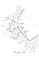
- FIG. 4 is an enlarged cross-sectional view of the front edge portion 21 shown in FIG. 3.
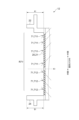
- FIG. FIG. 2 is a view of the outer surface 25 of the leading edge 21 of the airfoil 20 as viewed from a direction perpendicular to the outer surface 25.
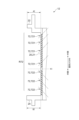
- FIG. 7 is a diagram showing an example of a cross section along the blade height direction at the position of the first film cooling hole row R71 in the leading edge portion 21 of the airfoil portion 20.
- FIG. 7 is an enlarged cross-sectional view of an outer first film cooling hole 711, which is a first film cooling hole 71 near the outer shroud 22 in FIG. 6.
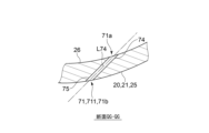
- FIG. 7 is an enlarged cross-sectional view of an inner first film cooling hole 712, which is a first film cooling hole 71 near the inner shroud 24 in FIG. 6.
- FIG. 7A is a diagram showing a QG-QG cross section in FIG. 7A.
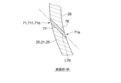
- FIG. It is a figure which shows the QH-QH cross section in FIG. 7B.
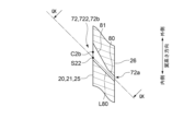
- FIG. 7 is a diagram showing an example of a cross section along the blade height direction at the position of the second film cooling hole row R72 in the leading edge portion 21 of the airfoil portion 20.
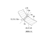
- FIG. 10 is an enlarged cross-sectional view of an outer second film cooling hole 721, which is a second film cooling hole 72 near the outer shroud 22 in FIG. 9.
- FIG. 10 is an enlarged cross-sectional view of an inner second film cooling hole 722, which is a second film cooling hole 72 near the inner shroud 24 in FIG. 9.
- FIG. 10A is a diagram showing a QJ-QJ cross section in FIG. 10A. It is a figure which shows the QK-QK cross section in FIG. 10B.
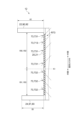
- FIG. 7 is a diagram showing an example of a cross section along the blade height direction at the position of the third film cooling hole row R73 in the leading edge portion 21 of the airfoil portion 20.
- FIG. 13 is an enlarged cross-sectional view of an outer third film cooling hole 731, which is a third film cooling hole 73 near the outer shroud 22 in FIG. 12.
- FIG. 13 is an enlarged cross-sectional view of an inner third film cooling hole 732, which is a third film cooling hole 73 near the inner shroud 24 in FIG. 12.
- FIG. FIG. 13A is a diagram showing a QL-QL cross section in FIG. 13A.
- FIG. 13B is a diagram showing a QM-QM cross section in FIG. 13B.
- FIG. 7 is a diagram showing a cross section of an airfoil portion 020 according to a first comparative embodiment perpendicular to the blade height direction.
- FIG. 7 is a diagram showing the relationship between the distance from hole row 07 (the film cooling hole row at the position corresponding to the second film cooling hole row R72) and the average film efficiency in the blade span direction.
- expressions such as “same,””equal,” and “homogeneous” that indicate that things are in an equal state do not only mean that things are exactly equal, but also have tolerances or differences in the degree to which the same function can be obtained. It also represents the existing state.
- expressions expressing shapes such as squares and cylinders do not only refer to shapes such as squares and cylinders in a strict geometric sense, but also include uneven parts and chamfers to the extent that the same effect can be obtained. Shapes including parts, etc. shall also be expressed.
- the expressions “comprising,”"comprising,””comprising,””containing,” or “having" one component are not exclusive expressions that exclude the presence of other components.
- FIG. 1 is a diagram showing a schematic configuration of a gas turbine 2 according to an embodiment.
- the gas turbine 2 includes a compressor 4, a combustor 6 for mixing compressed air generated by the compressor 4 with fuel and combusting it, and a combustion gas generated by the combustor 6.
- the turbine 8 includes a rotor 9 (turbine rotor), a turbine casing 10 that accommodates the rotor 9, and a plurality of turbine stator blades 12 (gas turbine stator blades) fixed to the inner surface of the turbine casing 10. and a plurality of turbine rotor blades 16 implanted in the rotor 9 so as to be arranged alternately in the axial direction with respect to the turbine stationary blades 12.
- circumferential direction means the circumferential direction of the gas turbine 2, that is, the circumferential direction of the rotor 9, unless otherwise specified
- axial direction means the axial direction of the gas turbine 2, that is, the axial direction of the rotor 9, unless otherwise specified.
- dial direction means the radial direction of the gas turbine 2, that is, the radial direction of the rotor 9, unless otherwise specified.
- FIG. 2 is a diagram showing an example of a cross section of the turbine stationary blade 12 along the blade height direction.
- turbine vane 12 includes an airfoil 20, an outer shroud 22, and an inner shroud 24.
- blade height direction means the blade height direction of the turbine stationary blades 12, that is, the blade height direction of the airfoil portion 20, and corresponds to the radial direction of the gas turbine 2, that is, the radial direction of the rotor 9.
- “outside in the blade height direction” means the outside in the radial direction of the gas turbine 2, that is, the outside in the radial direction of the rotor 9, and "inside in the blade height direction” means the radial direction of the gas turbine 2. , that is, the inside of the rotor 9 in the radial direction.
- the airfoil 20 has an airfoil cross-sectional shape defined by a pressure surface and a suction surface, and inside the airfoil 20 is formed an outer shroud 22 in the blade height direction.
- a later-described intra-blade cavity is formed that communicates the outer cavity 32 with an inner cavity 34 formed inside the inner shroud 24 in the blade height direction.
- the outer cavity 32 is a space formed between the outer shroud 22 and the turbine casing 10 (see FIG. 1), and the inner cavity 34 is formed between the inner shroud 24 and an inner peripheral diaphragm (not shown). It is a space where
- a first film cooling hole row R71, a second film cooling hole row R72, and a third film cooling hole row R73 are formed on the leading edge portion 21 of the airfoil portion 20.
- leading edge refers to a portion of the airfoil 20 that includes the most upstream position E2 of the airfoil 20 in the axial direction, for example, as shown in FIG. This refers to the portion opposite to the trailing edge TE of the airfoil 20 across the edge partition wall 48.
- the first film cooling hole row R71 includes a plurality of first film cooling holes 71 arranged along the blade height direction.
- the second film cooling hole row R72 includes a plurality of second film cooling holes 72 arranged along the blade height direction.
- the third film cooling hole row R73 includes a plurality of third film cooling holes 73 arranged along the blade height direction.
- the second film cooling hole row R72 is arranged between the first film cooling hole row R71 and the third film cooling hole row R73.
- the outer shroud 22 is connected to the outer end 20a of the airfoil portion 20 in the blade height direction, and is formed in a substantially plate shape along a plane that intersects with the blade height direction.
- the outer shroud 22 forms an outer peripheral wall 33 of a combustion gas flow path 31 in the turbine 8 (main flow path for combustion gas in the turbine 8).
- the upstream side in the axial direction means the upstream side of the main stream of combustion gas of the turbine 8 (the flow of combustion gas flowing through the flow path 31) in the axial direction
- “the downstream side in the axial direction” “side” means the downstream side of the mainstream of the combustion gas of the turbine 8 in the axial direction.
- the inner shroud 24 is connected to the inner end 20b of the airfoil portion 20 in the blade height direction, and is formed in a substantially plate shape along a plane that intersects with the blade height direction.
- the inner shroud 24 forms an inner circumferential wall 35 of a combustion gas flow path 31 in the turbine 8 (main flow path for combustion gas in the turbine 8).
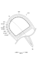
- FIG. 3 is a diagram showing an example of a cross section of the turbine stationary blade 12 shown in FIG. 2, perpendicular to the blade height direction.
- the turbine stator blade 12 described below may be, for example, the first stage turbine stator blade 12 used in the turbine 8 under the highest temperature conditions.
- the airfoil portion 20 of the turbine stationary blade 12 has an intra-blade cavity between a suction surface forming wall 38 that forms a suction surface 36 and a suction surface forming wall 38 that forms a pressure surface 40. 42 and a pressure surface forming wall 44 .
- Each of the negative pressure surface forming wall 38 and the pressure surface forming wall 44 may have a curved plate shape having a substantially constant thickness.
- the intra-blade cavity 42 is formed inside the airfoil 20 from one end of the airfoil 20 to the other end along the blade height direction.
- the intrafoil cavity 42 of the airfoil 20 is provided with a leading edge bulkhead 48.
- the leading edge partition wall 48 is integrally formed with the airfoil portion 20, for example, by casting, and extends from the inner surface 39 of the suction surface forming wall 38 to the inner surface 45 of the pressure surface forming wall 44, and extends from the inner surface of the airfoil cavity 42 in front. It is configured to be divided into an edge cavity 46 and a rear edge cavity 49.
- the front edge partition wall 48 may have a plate shape with a substantially constant thickness.
- the leading edge cavity 46 of the airfoil 20 is provided with an insert 50.
- the insert 50 is formed into a tube shape made of, for example, a sheet metal so as to extend from one end of the airfoil section 20 to the other end along the blade height direction, and is inserted into the leading edge side cavity 46 .
- the inner space 51 of the insert 50 communicates with the outer cavity 32 (see FIG. 2), and the compressed air supplied from the compressor 4 to the outer cavity 32 is transferred from the outer cavity 32 to the inner space 51 of the insert 50 as cooling air. Supplied.
- the insert 50 has a plurality of impingement cooling holes for impingement cooling the wall surface (the inner surface 39 of the suction surface forming wall 38 and the inner surface 45 of the pressure surface forming wall 44) forming the leading edge side cavity 46 in the airfoil section 20. 52 is formed.
- the plurality of impingement cooling holes 52 are formed in a portion of the insert 50 facing the negative pressure surface forming wall 38 and a portion of the insert 50 facing the pressure surface forming wall 44.
- the above-mentioned first film cooling hole row R71, second film cooling hole row R72, and third film cooling hole row R73 are formed on the leading edge portion 21 of the airfoil portion 20.
- the first film cooling hole row R71 includes a plurality of first film cooling holes 71 arranged along the blade height direction
- the second film cooling hole row R72 includes a plurality of first film cooling holes 71 arranged along the blade height direction.
- the third film cooling hole row R73 includes a plurality of third film cooling holes 73 arranged along the blade height direction.
- the second film cooling hole row R72 is arranged between the first film cooling hole row R71 and the third film cooling hole row R73.
- each of the first film cooling hole 71, the second film cooling hole 72, and the third film cooling hole 73 is located closer to the camber line CL in a cross section perpendicular to the blade height direction in the airfoil portion 20. is also located on the pressure surface 40 side. That is, each of the first film cooling hole row R71, the second film cooling hole row R72, and the third film cooling hole row R73 is formed on the pressure surface forming wall 44.
- the cooling air supplied from the outside of the turbine stator blade 12 (for example, the compressor 4) to the intra-blade cavity 42 of the turbine stator blade 12 is supplied to the first film cooling hole 71, It flows out of the airfoil 20 through either the second film cooling hole 72 or the third film cooling hole 73, flows along the surface of the airfoil 20, and performs film cooling of the surface of the airfoil 20. .
- the air is ejected from the airfoil 20 to impingement-cool the wall surface forming the leading edge cavity 46 of the airfoil 20.
- the cooling air that is ejected from the plurality of impingement cooling holes 52 of the insert 50 and performs impingement cooling of the pressure surface forming wall 44 is sent to the first film cooling hole 71, the second film cooling hole 72, or the third film cooling hole 73. through the leading edge 21 of the airfoil 20 and flows along the surface of the airfoil 20 to provide film cooling of the surface of the airfoil 20.
- FIG. 4 is an enlarged cross-sectional view of the front edge portion 21 shown in FIG.
- each of the first film cooling holes 71 is formed as a through hole passing through the front edge 21, and extends from the inlet 71a of the first film cooling hole 71 to the outlet 71b of the front edge 21. It extends along a direction inclined with respect to the thickness direction (direction perpendicular to each of the outer surface 25 and inner surface 26 of the front edge portion 21).
- each of the first film cooling holes 71 extends from the inlet 71a to the outlet 71b of the first film cooling hole 71 in a plane perpendicular to the blade height direction (the airfoil 20 shown in FIG. It extends along a direction inclined with respect to the cross-section of
- the first plane H1 is defined as the first plane H1.
- Each of the film cooling holes 71 extends from the inlet 71a to the outlet 71b of the first film cooling hole 71 along a direction inclined with respect to the first plane H1. Furthermore, the center C1b of the outlet 71b of the first film cooling hole 71 is located at a point where the flow F of combustion gas along the leading edge 21 (the above-mentioned It is located on the downstream side of the main stream of combustion gas flowing through the flow path 31.
- each of the second film cooling holes 72 is formed as a through hole passing through the front edge 21, and extends from the inlet 72a of the second film cooling hole 72 to the outlet 72b of the front edge 21. Extends along a direction inclined to the wall thickness direction.
- each of the second film cooling holes 72 extends from the inlet 72a to the outlet 72b of the second film cooling hole 72 along a direction oblique to a plane perpendicular to the blade height direction. extend.
- the second plane H2 is defined as the second plane H2.
- the outlet 72b of the film cooling hole 72 is located at a position P2 where the second plane H2 and the outer surface 25 of the front edge 21 intersect.
- each of the third film cooling holes 73 is formed as a through hole passing through the front edge 21, and extends from the inlet 73a of the third film cooling hole 73 to the outlet 73b of the front edge 21. Extends along a direction inclined to the wall thickness direction.
- each of the third film cooling holes 73 extends from the inlet 73a to the outlet 73b of the third film cooling hole 73 along a direction inclined with respect to a plane perpendicular to the blade height direction. extend.
- a plane including the thickness direction of the leading edge part 21 and the blade height direction at the center C3a of the inlet 73a of the third film cooling hole 73 is defined as a third plane H3
- the center C3b of the outlet 73b of the film cooling hole 73 is located downstream of the flow F of combustion gas along the leading edge 21 from the position P3 where the third plane H3 and the outer surface 25 of the leading edge 21 intersect.
- the intersection of the camber line CL and the outer surface 25 of the leading edge 21 is E1
- the airfoil 20 in the axial direction of the gas turbine 2 is The center C1b of the outlet 71b of the first film cooling hole 71 is located between the intersection E1 on the outer surface 25 of the airfoil 20 and the most upstream position E2
- the center C2b of the outlet 72b of the third film cooling hole 72 is located on the opposite side of the intersection E1 (the leading edge partition wall 48 side) across the most upstream position E2 on the outer surface 25 of the airfoil 20, and the center C2b of the outlet 72b of the third film cooling hole 73
- the center C3b of is located on the opposite side of the intersection E1 across the most upstream position E2 on the outer surface 25 of the airfoil portion 20.
- each of the first film cooling holes 71, the second film cooling holes 72, and the third film cooling holes 73 has the following characteristics in the axial direction: It is located upstream of the position G where the pressure surface forming wall 44 and the front edge partition wall 48 connect.
- FIG. 5 is a view of the outer surface 25 of the leading edge 21 of the airfoil 20 viewed from a direction perpendicular to the outer surface 25.
- FIG. 6 is a diagram showing an example of a cross section along the blade height direction at the position of the first film cooling hole row R71 in the leading edge portion 21 of the airfoil portion 20.
- FIG. 7A is an enlarged cross-sectional view of an outer first film cooling hole 711, which is the first film cooling hole 71 near the outer shroud 22 in FIG. 6.
- FIG. 7B is an enlarged cross-sectional view of the inner first film cooling hole 712, which is the first film cooling hole 71 near the inner shroud 24 in FIG.
- FIG. 8A is a diagram showing a QG-QG cross section in FIG. 7A.
- FIG. 8B is a diagram showing a QH-QH cross section in FIG. 7B.
- FIG. 9 is a diagram showing an example of a cross section along the blade height direction at the position of the second film cooling hole row R72 in the leading edge portion 21 of the airfoil portion 20.
- FIG. 10A is an enlarged cross-sectional view of the second outer film cooling hole 721, which is the second film cooling hole 72 near the outer shroud 22 in FIG.
- FIG. 10B is an enlarged cross-sectional view of the inner second film cooling hole 722, which is the second film cooling hole 72 near the inner shroud 24 in FIG.
- FIG. 11A is a diagram showing a QJ-QJ cross section in FIG. 10A.
- FIG. 11B is a diagram showing a QK-QK cross section in FIG. 10B.
- FIG. 12 is a diagram showing an example of a cross section along the blade height direction at the position of the third film cooling hole row R73 in the leading edge portion 21 of the airfoil portion 20.
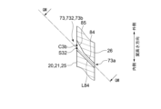
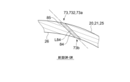
- FIG. 13A is an enlarged cross-sectional view of the third outer film cooling hole 731, which is the third film cooling hole 73 near the outer shroud 22 in FIG. 12.
- FIG. 13B is an enlarged cross-sectional view of the inner third film cooling hole 732, which is the third film cooling hole 73 near the inner shroud 24 in FIG. 12.
- FIG. 14A is a diagram showing a QL-QL cross section in FIG. 13A.
- FIG. 14B is a diagram showing a QM-QM cross section in FIG. 13B.
- the plurality of first film cooling holes 71 belonging to the first film cooling hole row R71 are connected to the plurality of outer first film cooling holes located outside the first position K1 in the blade height direction. It includes a cooling hole 711 and a plurality of inner first film cooling holes 712 located inside the first position K1 in the blade height direction.
- the first position K1 is a position closer to the inner shroud 24 than the center of the airfoil portion 20 in the blade height direction.
- the first outer film cooling holes 711 move inward in the blade height direction from the inlet 71a of the first outer film cooling hole 711 to the outlet 71b of the first outer film cooling hole 711. It extends to
- the inner first film cooling holes 712 move outward in the blade height direction from the inlet 71a of the inner first film cooling hole 712 to the outlet 71b of the inner first film cooling hole 712. It extends to
- the plurality of second film cooling holes 72 belonging to the second film cooling hole row R72 are arranged in a plurality of outer second films located outside the first position K1 in the blade height direction. It includes a cooling hole 721 and a plurality of inner second film cooling holes 722 located inside the first position K1 in the blade height direction.
- the second outer film cooling holes 721 move inward in the blade height direction from the inlet 72a of the second outer film cooling hole 721 to the outlet 72b of the second outer film cooling hole 721. It extends to
- the inner second film cooling holes 722 move outward in the blade height direction from the inlet 72a of the inner second film cooling hole 722 to the outlet 72b of the inner second film cooling hole 722. It extends to
- the plurality of third film cooling holes 73 belonging to the third film cooling hole row R73 are arranged in a plurality of outer third films located outside the first position K1 in the blade height direction. It includes a cooling hole 731 and a plurality of inner third film cooling holes 732 located inside the first position K1 in the blade height direction.
- the third outer film cooling holes 731 move inward in the blade height direction from the inlet 73a of the third outer film cooling hole 731 to the outlet 73b of the third outer film cooling hole 731. It extends to
- the inner third film cooling holes 732 extend outward in the blade height direction from the inlet 73a of the inner third film cooling hole 732 toward the outlet 73b of the inner third film cooling hole 732. It extends to
- the outer first film cooling hole 711 includes a circular hole portion 74 and a shaped hole portion 75.
- the circular hole portion 74 is a portion of the first outer film cooling hole 711 on the inlet 71a side, and has a circular cross-sectional shape.
- the cross-sectional area of the circular hole 74 is constant regardless of the position of the circular hole 74 in the direction of the axis L74.
- the shaped hole portion 75 is a portion of the outer first film cooling hole 711 on the outlet 71b side, and is connected to the circular hole portion 74 .
- the cross-sectional area of the shaped hole portion 75 increases toward the outlet 71b of the outer first film cooling hole 711 (the exit of the shaped hole portion 75).
- the shaped hole portion 75 has a cross-sectional area expanded only inward in the blade height direction with respect to the circular hole portion 74 when viewed in the direction of the axis L74 of the circular hole portion 74.
- the cross-sectional area is not extended to the outside of the direction.
- the shaped hole portion 75 has a cross-sectional area that is not expanded relative to the circular hole portion 74 in a direction perpendicular to the blade height direction when viewed in the direction of the axis L74 of the circular hole portion 74.
- the center C1b of the outlet 71b of the first outer film cooling hole 711 is located inward in the blade height direction from the extension line of the axis L74 of the circular hole portion 74 of the first outer film cooling hole 711.
- the center C1b of the outlet 71b of the first outer film cooling hole 711 is defined by the extension line of the axis L74 of the circular hole 74 of the first outer film cooling hole 711 and the outlet 71b of the first outer film cooling hole 711. It is located inside the intersection S11 in the blade height direction.
- the inner first film cooling hole 712 includes a circular hole portion 76 and a shaped hole portion 77.
- the circular hole portion 76 is a portion of the inner first film cooling hole 712 on the inlet 71a side, and has a circular cross-sectional shape.
- the cross-sectional area of the circular hole 76 is constant regardless of the position of the circular hole 76 in the direction of the axis L76.
- the shaped hole portion 77 is a portion of the inner first film cooling hole 712 on the outlet 71b side, and is connected to the circular hole portion 76 .
- the cross-sectional area of the shaped hole portion 77 increases toward the outlet 71b of the inner first film cooling hole 712 (the exit of the shaped hole portion 77).
- the shaped hole portion 77 has a cross-sectional area expanded only outward in the blade height direction with respect to the circular hole portion 76 when viewed in the direction of the axis L76 of the circular hole portion 76.
- the cross-sectional area is not expanded inward in the direction.
- the shaped hole portion 77 has a cross-sectional area that is not expanded relative to the circular hole portion 76 in the direction orthogonal to the blade height direction when viewed in the direction of the axis L76 of the circular hole portion 76.
- the center C1b of the outlet 71b of the inner first film cooling hole 712 is located on the outer side in the blade height direction than the extension line of the axis L76 of the circular hole portion 76 of the inner first film cooling hole 712.
- the center C1b of the outlet 71b of the first inner film cooling hole 712 is defined by the extension line of the axis L76 of the circular hole 76 of the first inner film cooling hole 712 and the outlet 71b of the first inner film cooling hole 712. It is located outside the intersection S12 in the blade height direction.
- the outer second film cooling hole 721 includes a circular hole portion 78 and a shaped hole portion 79.
- the circular hole portion 78 is a portion of the second outer film cooling hole 721 on the inlet 72a side, and has a circular cross-sectional shape.
- the cross-sectional area of the circular hole 78 is constant regardless of the position of the circular hole 78 in the direction of the axis L78.
- the shaped hole portion 79 is a portion of the outer second film cooling hole 721 on the outlet 72b side, and is connected to the circular hole portion 78.
- the cross-sectional area of the shaped hole portion 79 increases toward the outlet 72b of the outer second film cooling hole 721 (the exit of the shaped hole portion 79).
- the shaped hole portion 79 has a cross-sectional area expanded only inward in the blade height direction with respect to the circular hole portion 78 when viewed in the direction of the axis L78 of the circular hole portion 78.
- the cross-sectional area is not extended to the outside of the direction.
- the shaped hole portion 79 has a cross-sectional area that is not expanded relative to the circular hole portion 78 in a direction perpendicular to the blade height direction when viewed in the direction of the axis L78 of the circular hole portion 78.
- the center C2b of the outlet 72b of the second outer film cooling hole 721 is located inward in the blade height direction from the extension line of the axis L78 of the circular hole portion 78 of the second outer film cooling hole 721.
- the center C2b of the outlet 72b of the second outer film cooling hole 721 is defined by the extension line of the axis L78 of the circular hole portion 78 of the second outer film cooling hole 721 and the outlet 72b of the second outer film cooling hole 721. It is located inside the intersection S21 in the blade height direction.
- the inner second film cooling hole 722 includes a circular hole portion 80 and a shaped hole portion 81.
- the circular hole portion 80 is a portion of the inner second film cooling hole 722 on the inlet 72a side, and has a circular cross-sectional shape.
- the cross-sectional area of the circular hole 80 is constant regardless of the position of the circular hole 80 in the direction of the axis L80.
- the shaped hole portion 81 is a portion of the inner second film cooling hole 722 on the outlet 72b side, and is connected to the circular hole portion 80.
- the cross-sectional area of the shaped hole 81 increases toward the outlet 72b of the inner second film cooling hole 722 (the exit of the shaped hole 81).
- the shaped hole portion 81 has a cross-sectional area expanded only outward in the blade height direction with respect to the circular hole portion 80 when viewed in the direction of the axis L80 of the circular hole portion 80.
- the cross-sectional area is not expanded inward in the direction.
- the shaped hole portion 81 has a cross-sectional area that is not expanded relative to the circular hole portion 80 in the direction orthogonal to the blade height direction when viewed in the direction of the axis L80 of the circular hole portion 80.
- the center C2b of the outlet 72b of the inner second film cooling hole 722 is located on the outer side in the blade height direction than the extension line of the axis L80 of the circular hole portion 80 of the inner second film cooling hole 722.
- the center C2b of the outlet 72b of the second inner film cooling hole 722 is the extension of the axis L80 of the circular hole 80 of the second inner film cooling hole 722 and the outlet 72b of the second inner film cooling hole 722. It is located outside the intersection S22 in the blade height direction.
- the third outer film cooling hole 731 includes a circular hole portion 82 and a shaped hole portion 83.
- the circular hole portion 82 is a portion of the third outer film cooling hole 731 on the inlet 73a side, and has a circular cross-sectional shape.
- the cross-sectional area of the circular hole 82 is constant regardless of the position of the circular hole 82 in the direction of the axis L82.
- the shaped hole portion 83 is a portion of the third outer film cooling hole 731 on the outlet 73b side, and is connected to the circular hole portion 82 .
- the cross-sectional area of the shaped hole portion 83 increases toward the outlet 73b of the third outer film cooling hole 731 (the exit of the shaped hole portion 83).
- the shaped hole portion 83 has a cross-sectional area expanded only inward in the blade height direction relative to the circular hole portion 82 when viewed in the direction of the axis L82 of the circular hole portion 82; The cross-sectional area is not extended to the outside of the direction. Further, the shaped hole portion 83 has a cross-sectional area that is not expanded relative to the circular hole portion 82 in the direction orthogonal to the blade height direction when viewed in the direction of the axis L82 of the circular hole portion 82.
- the center C3b of the outlet 73b of the third outer film cooling hole 731 is located inward in the blade height direction from the extension line of the axis L82 of the circular hole portion 82 of the third outer film cooling hole 731.
- the center C3b of the outlet 73b of the third outer film cooling hole 731 is connected to the extension line of the axis L82 of the circular hole portion 82 of the third outer film cooling hole 731 and the outlet 73b of the third outer film cooling hole 731. It is located inside the intersection S31 in the blade height direction.
- the inner third film cooling hole 732 includes a circular hole portion 84 and a shaped hole portion 85.
- the circular hole portion 84 is a portion of the third inner film cooling hole 732 on the inlet 73a side, and has a circular cross-sectional shape.
- the cross-sectional area of the circular hole 84 is constant regardless of the position of the circular hole 84 in the direction of the axis L84.
- the shaped hole portion 85 is a portion of the inner third film cooling hole 732 on the outlet 73b side, and is connected to the circular hole portion 84.
- the cross-sectional area of the shaped hole portion 85 increases toward the outlet 73b of the inner third film cooling hole 732 (the exit of the shaped hole portion 83).
- the shaped hole portion 85 has a cross-sectional area expanded only outward in the blade height direction with respect to the circular hole portion 84 when viewed in the direction of the axis L84 of the circular hole portion 84.
- the cross-sectional area is not expanded inward in the direction.
- the shaped hole portion 85 has a cross-sectional area that is not expanded relative to the circular hole portion 84 in the direction orthogonal to the blade height direction when viewed in the direction of the axis L84 of the circular hole portion 84.
- the center C3b of the outlet 73b of the third inner film cooling hole 732 is located on the outer side in the blade height direction than the extension line of the axis L84 of the circular hole 84 of the third inner film cooling hole 732.
- the center C3b of the outlet 73b of the third inner film cooling hole 732 is defined by the extension line of the axis L84 of the circular hole portion 84 of the third inner film cooling hole 732 and the outlet 73b of the third inner film cooling hole 732. It is located outside the intersection S32 in the blade height direction.
- the axis of the third film cooling hole 73 (the axis L82 of the circular hole portion 82 of the outer third film cooling hole 731 in FIG. 13, the circular hole portion of the inner third film cooling hole 732 in FIG. 13B)
- the amount of protrusion of the outer shroud 22 and the inner shroud 24 from the leading edge 21 in the direction perpendicular to the blade height direction is large.
- the distance V90 between the first position K1 and the large shroud 90 in the blade height direction is , is larger than the distance V91 between the first position K1 and the small shroud 91 in the blade height direction.
- the distance V90 between the first position K1 and the large shroud 90 in the blade height direction is , is larger than the distance V91 between the first position K1 and the small shroud 91 in the blade height direction.
- the amount of protrusion of the outer shroud 22 from the leading edge 21 in the direction orthogonal to the blade height direction is A3
- the amount of protrusion of the inner shroud 24 from the leading edge 21 in the direction perpendicular to the blade height direction is B3, then A3>B3, so the outer shroud 22 is the large shroud 90 and the inner shroud 24 is the small shroud 91. It is.
- the axis of the first film cooling hole 71 (the axis L74 of the circular hole portion 74 of the outer first film cooling hole 711 in FIG. 7A, the circular hole portion of the inner first film cooling hole 712 in FIG. 7B), 76 axis L76 and their extensions) and the blade height direction
- the amount of protrusion of the outer shroud 22 from the leading edge 21 in the direction perpendicular to the blade height direction is A1
- the amount of protrusion of the inner shroud 24 in the direction perpendicular to the blade height direction is defined as B1.
- the axis of the second film cooling hole 72 (the axis L78 of the circular hole portion 78 of the outer second film cooling hole 721 in FIG. 10A, the circular axis L78 of the inner second film cooling hole 722 in FIG. 10B),
- the amount of protrusion of the outer shroud 22 from the leading edge 21 in the direction perpendicular to the blade height direction is A2
- the amount of protrusion of the inner shroud 24 from the inner shroud 21 in the direction orthogonal to the blade height direction is defined as B2.
- the axis of the third film cooling hole 73 (the axis L82 of the circular hole portion 82 of the outer third film cooling hole 731 in FIG. 13A, the circular axis L82 of the inner third film cooling hole 732 in FIG. 13B), In a cross section along the blade height direction including the axis L84 of the hole 84 and their extension line, the amount of protrusion of the outer shroud 22 from the leading edge 21 in the direction perpendicular to the blade height direction is A3, the leading edge The amount of protrusion of the inner shroud 24 from the portion 21 in the direction perpendicular to the blade height direction is defined as B3.
- the outer shroud 22 and the inner shroud 24 the one having the largest protrusion amount among the protrusion amounts A1, A2, A3, B1, B2, and B3 is defined as the large shroud 92
- the outer shroud 22 and the inner shroud 24 that is not the large shroud 92 is defined as the small shroud 93
- the distance V92 between the first position K1 in the blade height direction and the large shroud 92 is the distance V92 between the first position K1 in the blade height direction and the small shroud 93. distance V93.
- the largest protrusion amount among the protrusion amounts A1, A2, A3, B1, B2, and B3 is A3, so the outer shroud 22 is the large shroud 92, and the inner shroud 22 is the large shroud 92.
- the shroud 24 is a small shroud 93.
- each of the first film cooling hole 71, the second film cooling hole 72, and the third film cooling hole 73 extends in a direction inclined with respect to the thickness direction of the front edge portion 21.
- the center C1b of the outlet 71b of the first film cooling hole 71 is located closer to the flow F of combustion gas along the leading edge 21 than the position P1 where the first plane H1 and the outer surface 25 of the leading edge 21 intersect.
- the outlet 72b of the second film cooling hole 72 is located at a position P2 where the second plane H2 and the outer surface 25 of the front edge 21 intersect, and the outlet 73b of the third film cooling hole 73
- the center C3b is located downstream of the flow F of the combustion gas along the leading edge 21 from the position P3 where the third plane H3 and the outer surface 25 of the leading edge 21 intersect.
- the second film cooling hole row R72 is arranged so that the second film cooling hole 72 is located at or near the stagnation point of the combustion gas flow on the outer surface 25 of the leading edge 21 (see FIG. 4).
- Cooling air for film cooling can be allowed to flow out along the outer surface 25 of the leading edge 21 towards. Therefore, film cooling of the outer surface 25 of the leading edge portion 21 can be effectively performed with a small amount of cooling air, and a decrease in film efficiency of film cooling of the blade surface can be suppressed while reducing the amount of cooling air.
- the first outer film cooling hole 711 located on the outer shroud 22 side in the blade height direction goes from the inlet 71a of the outer first film cooling hole 711 to the outlet 71b. Therefore, as the outer first film cooling hole 711 goes from the inlet 71a of the outer first film cooling hole 711 to the outlet 71b, the outer first film cooling hole 711 extends outward in the blade height direction.
- the jig and the outer shroud are 22 can be suppressed.
- the first inner film cooling hole 712 located on the inner shroud 24 side in the blade height direction goes from the inlet 71a of the inner first film cooling hole 712 to the outlet 71b. Since the inner first film cooling holes 712 extend outward in the blade height direction as the inner first film cooling holes 712 go from the inlet 71a to the outlet 71b of the inner first film cooling holes 712, they extend inward in the blade height direction.
- interference between the jig and the inner shroud 24 is reduced. Can be suppressed.
- the outer second film cooling holes 721 located on the outer shroud 22 side in the blade height direction are directed from the inlet 72a of the outer second film cooling hole 721 to the outlet 72b. Since the outer second film cooling holes 721 extend inward in the blade height direction as the outer second film cooling holes 721 go from the inlet 72a to the outlet 72b of the outer second film cooling holes 721, they extend outward in the blade height direction. Compared to the case where the outer second film cooling holes 721 are formed from the outer surface 25 side of the airfoil portion 20 by laser processing, for example, the jig and the outer shroud are 22 can be suppressed.
- the inner second film cooling holes 722 located on the inner shroud 24 side in the blade height direction are directed from the inlet 72a of the inner second film cooling hole 722 to the outlet 72b. Since the inner second film cooling holes 722 extend outward in the blade height direction as the inner second film cooling holes 722 go from the inlet 72a to the outlet 72b of the inner second film cooling holes 722, they extend inward in the blade height direction.
- interference between the jig and the inner shroud 24 is reduced. Can be suppressed.
- the third outer film cooling hole 731 located on the outer shroud 22 side in the blade height direction goes from the inlet 73a of the third outer film cooling hole 731 to the outlet 73b. Therefore, as the outer third film cooling hole 731 goes from the inlet 73a of the outer third film cooling hole 731 to the outlet 73b, the outer third film cooling hole 731 extends outward in the blade height direction. Compared to the case where the outer third film cooling hole 731 is formed from the outer surface 25 side of the airfoil portion 20 by laser processing, for example, the jig and the outer shroud are 22 can be suppressed.
- the inner third film cooling hole 732 located on the inner shroud 24 side in the blade height direction goes from the inlet 73a of the inner third film cooling hole 732 to the outlet 73b. Since the third inner film cooling hole 732 extends outward in the blade height direction as the inner third film cooling hole 732 goes from the inlet 73a of the inner third film cooling hole 732 to the outlet 73b, the third inner film cooling hole 732 extends inward in the blade height direction.
- interference between the jig and the inner shroud 24 is reduced. Can be suppressed.
- each of the outer third film cooling hole 731 and the inner third film cooling hole 732 by, for example, laser processing using a jig from the outer surface 25 side of the airfoil portion 20,
- the outer shroud 22 has a larger protrusion from the leading edge 21 in a direction perpendicular to the blade height direction
- the inner shroud 24 has a smaller protrusion from the leading edge 21 in a direction perpendicular to the blade height.
- the problem of interference with the jig is more likely to occur. Therefore, as shown in FIG. 12 etc., the first position is the boundary between the range in the blade height direction where the outer third film cooling holes 731 are formed and the range where the inner third film cooling holes 732 are formed.
- each of the first film cooling holes 71 to third film cooling holes 73 from the outer surface 25 side of the airfoil portion 20 by, for example, laser processing using a jig
- the blade height from the leading edge portion 21 The large shroud 92 having the largest protrusion amount A3 in the direction perpendicular to the direction is more likely to cause the problem of interference with the jig than the small shroud 93.
- each of the first film cooling holes 71 to third film cooling holes 73 can be formed while suppressing interference with each of the shroud 22 and the inner shroud 24.
- each of the first film cooling hole 71, the second film cooling hole, and the third film cooling hole 73 is arranged in the blade height direction. It extends along a direction oblique to a perpendicular plane. For this reason, the front edge 21 Film cooling of the outer surface 25 of the blade can be effectively performed with a small amount of cooling air, and a decrease in film efficiency of film cooling of the blade surface can be suppressed while reducing the amount of cooling air.
- each shaped hole part 75 of the outer first film cooling hole 711, the outer second film cooling hole 721, and the outer third film cooling hole 731 By expanding the cross-sectional area of the holes 79 and 83 only inward in the blade height direction relative to the circular holes 74, 78, and 82, respectively, the first outer film cooling hole 711, the second outer film cooling hole 721, and the outer second film cooling hole 721 are formed.
- Each of the three film cooling holes 731 can be easily formed by laser processing or the like.
- the shape hole portions 77, 81, 85 of the first inner film cooling hole 712, the second inner film cooling hole 722, and the third inner film cooling hole 732 are set at a blade height relative to the circular hole portions 76, 80, 84, respectively.
- FIG. 15 is a diagram showing a cross section of the turbine stationary blade 012 according to the first comparative embodiment perpendicular to the blade height direction.
- FIG. 16 shows the relationship between the distance from the second film cooling hole row R72 and the average film efficiency in the blade span direction in the turbine stator blade 12 according to the above embodiment, and the third row in the turbine stator blade 012 according to the first comparative embodiment.
- 7 is a diagram showing the relationship between the distance from the first film cooling hole row 07 (the film cooling hole row at the position corresponding to the second film cooling hole row R72) and the average film efficiency in the blade span direction.
- each of the film cooling hole rows 07 is arranged along the blade height direction. It includes a plurality of arranged film cooling holes 007.
- the film cooling holes 007 have a circular cross-sectional shape, and the thickness direction of the leading edge portion 021 at the center of the inlet of the film cooling hole 007 and the blade height direction are If the containing plane is defined as a vertical plane, the exit of the film cooling hole 007 is located at a position where the vertical plane intersects with the outer surface 025 of the front edge portion 021.
- the solid line indicates the relationship between the distance from the second film cooling hole row R72 in the turbine stationary blade 12 according to the above embodiment and the average film efficiency in the blade span direction
- the broken line indicates the relationship between the average film efficiency in the blade span direction
- 2 shows the relationship between the distance from the third film cooling hole row 07 in the turbine stator blade 012 and the average film efficiency in the blade span direction
- the dashed line indicates the distance from the third film cooling hole row 07 in the turbine stator blade 012.
- the relationship between the distance from the central film cooling hole row 07 in the turbine stationary blade 012 and the average film efficiency in the blade span direction is shown for a second comparative embodiment in which the number of rows is reduced by two to three rows.
- the number of film cooling hole rows 07 is reduced from five to three, compared to the first comparative embodiment, and thus the film efficiency is reduced.
- the third film cooling hole row R73 is It can be seen that since the shaped holes 83 and 85 are included, the film efficiency is improved on the downstream side of the third film cooling hole row R73 in the flow direction of combustion gas along the leading edge 21. In this manner, in the turbine stationary blade 12, the outer surface 25 of the leading edge portion 21 can be effectively film-cooled with a small amount of cooling air, and the film cooling efficiency of the blade surface can be improved while reducing the amount of cooling air. can suppress the decline in
- the shaped hole 75 when viewed in the direction of the axis L74 of the circular hole 74, the shaped hole 75 may have a cross-sectional area expanded not only inside in the blade height direction but also outside with respect to the circular hole 74, and The cross-sectional area may be expanded in a direction perpendicular to the blade height direction.
- the shaped hole portion 77 may have a cross-sectional area expanded not only to the outside in the blade height direction but also to the inside with respect to the circular hole portion 76 when viewed in the direction of the axis L76 of the circular hole portion 76.
- the cross-sectional area may be expanded in a direction perpendicular to the blade height direction.
- the shaped hole portion 79 may have a cross-sectional area expanded not only inwardly in the blade height direction but also outwardly with respect to the circular hole portion 78 when viewed in the direction of the axis L78 of the circular hole portion 78.
- the cross-sectional area may be expanded in a direction perpendicular to the blade height direction.
- the shaped hole portion 81 may have a cross-sectional area expanded not only to the outside in the blade height direction but also to the inside with respect to the circular hole portion 80 when viewed in the direction of the axis L80 of the circular hole portion 80.
- the cross-sectional area may be expanded in a direction perpendicular to the blade height direction.
- the shaped hole portion 83 may have a cross-sectional area expanded not only inwardly in the blade height direction but also outwardly with respect to the circular hole portion 82 when viewed in the direction of the axis L82 of the circular hole portion 82.
- the cross-sectional area may be expanded in a direction perpendicular to the blade height direction.
- the shaped hole portion 85 may have a cross-sectional area expanded not only to the outside in the blade height direction but also to the inside with respect to the circular hole portion 84 when viewed in the direction of the axis L84 of the circular hole portion 84.
- the cross-sectional area may be expanded in a direction perpendicular to the blade height direction.
- a gas turbine stationary blade includes: A first film cooling hole row (for example, the above-mentioned first film cooling hole row R71) including a plurality of first film cooling holes (for example, the above-mentioned plurality of first film cooling holes 71) arranged along the blade height direction.
- a first film cooling hole row for example, the above-mentioned first film cooling hole row R71
- a plurality of first film cooling holes for example, the above-mentioned plurality of first film cooling holes 71
- a second film cooling hole row (for example, the above-mentioned second film cooling hole row R72) including a plurality of second film cooling holes (for example, the above-mentioned plurality of second film cooling holes 72) arranged along the blade height direction.
- a third film cooling hole row (for example, the above-mentioned third film cooling hole row R73) including a plurality of third film cooling holes (for example, the above-mentioned third film cooling hole 73) arranged along the blade height direction; , is formed,
- the second film cooling hole row is arranged between the first film cooling hole row and the third film cooling hole row,
- the first film cooling hole extends in a direction oblique to the thickness direction of the front edge, and is located at the center of the entrance (for example, the above-mentioned inlet 71a) of the first film cooling hole (for example, the above-mentioned inlet 71a).
- a plane including the thickness direction of the leading edge portion and the blade height direction at the center C1a) is defined as a first plane (for example, the above-mentioned first plane H1)
- the exit of the first film cooling hole for example, the above-mentioned The center of the exit 71b
- the center C1b is closer to the leading edge than the position where the first plane and the outer surface of the leading edge (e.g., the outer surface 25 described above) intersect (e.g., the position P1 described above).
- located downstream of the flow of combustion gases e.g.
- the second film cooling hole extends in a direction inclined with respect to the thickness direction of the front edge, and is located at the center of the entrance (for example, the above-mentioned inlet 72a) of the second film cooling hole (for example, the above-mentioned inlet 72a).
- a plane including the thickness direction of the leading edge and the blade height direction at the center C2a) is defined as a second plane (for example, the above-mentioned second plane H2)
- the exit of the second film cooling hole is located at a position where the second plane and the outer surface of the leading edge intersect (for example, the above-mentioned position P2)
- the third film cooling hole extends in a direction inclined with respect to the thickness direction of the front edge, and is located at the center of the entrance (for example, the above-mentioned inlet 73a) of the third film cooling hole (for example, the above-mentioned inlet 73a).
- a plane including the thickness direction of the leading edge and the blade height direction at the center C3a) is defined as a third plane (for example, the above-mentioned third plane H3)
- the exit of the third film cooling hole for example, the above-mentioned The center of the outlet 73b
- the center C3b described above is located closer to the combustion gas along the leading edge than the position where the third plane and the outer surface of the leading edge intersect (for example, the position P3 described above). located on the downstream side of a stream (eg, stream F mentioned above).
- the first film cooling hole row and the second film are each arranged along the blade height direction at the leading edge exposed to the flow of high-temperature combustion gas.
- a cooling hole row and a third film cooling hole row are formed.
- each of the first film cooling hole 71, the second film cooling hole 72, and the third film cooling hole 73 extends in a direction inclined with respect to the thickness direction of the front edge portion 21, and
- the center of the outlet of the film cooling hole is located downstream of the flow of combustion gas along the leading edge from the point where the first plane intersects with the outer surface of the leading edge, and the outlet of the second film cooling hole is located on the downstream side of the flow of combustion gas along the leading edge.
- the airfoil shape can be improved.
- cooling air can flow out. Therefore, we provide a gas turbine stationary blade that can effectively perform film cooling of the outer surface of the leading edge with a small amount of cooling air, and can suppress a decrease in film efficiency of film cooling of the blade surface while reducing the amount of cooling air. can do.
- Each of the first film cooling hole, the second film cooling hole, and the third film cooling hole has a camber line (for example, the above-mentioned camber line CL) in a cross section perpendicular to the blade height direction in the airfoil portion.
- the pressure surface for example, the above-mentioned pressure surface 40
- the pressure surface is located closer to the pressure surface (for example, the above-mentioned pressure surface 40).
- the stagnation point of the flow of combustion gas on the outer surface of the leading edge of the airfoil occurs on the pressure side side of the camber line. on the outer surface of the leading edge of the airfoil by locating the second film cooling hole array such that the second film cooling holes are located at or near the stagnation point of the combustion gas flow on the outer surface of the edge.
- Cooling air for film cooling can be flowed out toward the downstream side of the flow of combustion gas from the first film cooling hole and the third film cooling hole on both sides of the boundary at the stagnation point of the flow of combustion gas. can. This makes it possible to effectively perform film cooling on the outer surface of the leading edge with a small amount of cooling air, and to reduce the amount of cooling air while suppressing a decrease in the film efficiency of film cooling on the blade surface. can be provided.
- E1 is the intersection of the camber line and the outer surface of the leading edge
- E2 is the most upstream position of the airfoil in the axial direction of the gas turbine.
- the outlet of the first film cooling hole is located between the intersection point E1 and the most upstream position E2 on the outer surface of the airfoil
- the outlet of the third film cooling hole is located on the outer surface of the airfoil. It is located on the opposite side of the intersection E1 across the most upstream position E2.
- film cooling is performed from the first film cooling hole and the third film cooling hole toward the downstream side of the flow of combustion gas on both sides of the most upstream position E2. This allows for effective film cooling of the outer surface of the leading edge with a small amount of cooling air, reducing the amount of cooling air while reducing the film efficiency of film cooling of the blade surface. It is possible to provide a gas turbine stationary blade that can suppress
- the outlet of the second film cooling hole is located on the opposite side of the intersection E1 across the most upstream position E2 on the outer surface of the airfoil section.
- gas turbine stator blade described in (4) above, it is possible to provide a gas turbine stator blade that can reduce the amount of cooling air while suppressing a decrease in the film efficiency of film cooling of the blade surface.
- the airfoil includes: a pressure surface forming wall (for example, the above-mentioned pressure surface forming wall 44) forming a pressure surface (for example, the above-mentioned pressure surface 40); a suction surface forming wall (for example, the above-mentioned suction surface forming wall 38) forming a suction surface (for example, the above-mentioned suction surface 36); a leading edge bulkhead (e.g., leading edge bulkhead 48 described above) extending from an inner surface of the suction surface forming wall to an inner surface of the pressure surface forming wall to divide the cavity inside the airfoil; In a cross section perpendicular to the blade height direction in the airfoil portion, each of the first film cooling hole, the second film cooling hole, and the third film cooling hole is located at the pressure surface in the axial direction of the gas turbine. It is located upstream of the position where the forming wall
- the gas turbine Since the stagnation point of the flow of combustion gas on the outer surface of the leading edge of the airfoil section occurs upstream of the position where the pressure surface forming wall and the leading edge partition wall connect, the gas turbine according to (5) above According to the stator vane, the second film cooling hole row is arranged such that the second film cooling hole is located at or near the stagnation point of the flow of combustion gas on the outer surface of the leading edge of the airfoil.
- Each of the first film cooling hole, the second film cooling hole, and the third film cooling hole extends along a direction inclined with respect to a plane perpendicular to the blade height direction.
- each of the first film cooling hole, the second film cooling hole, and the third film cooling hole extends along the thickness direction of the leading edge portion.
- film cooling of the outer surface of the leading edge can be effectively performed with a smaller amount of cooling air, and while reducing the amount of cooling air, it is possible to suppress the decline in film efficiency of film cooling of the blade surface.
- Stator blades can be provided.
- the plurality of third film cooling holes are the plurality of outer third film cooling holes (for example, the plurality of outer third film cooling holes described above) located outside the first position (for example, the above-mentioned first position K1) in the blade height direction.
- the third outer film cooling hole extends inward in the blade height direction from the inlet (for example, the above-mentioned inlet 73a) to the outlet (for example, the above-mentioned outlet 73b) of the outer third film cooling hole.
- the inner third film cooling hole extends outward in the blade height direction from the inlet (for example, the above-mentioned inlet 73a) to the outlet (for example, the above-mentioned outlet 73b) of the inner third film cooling hole.
- the inner third film cooling hole extends outward in the blade height direction from the inlet to the outlet of the inner third film cooling hole, the inner third film cooling hole extends outward in the blade height direction.
- the inner third film is formed by laser machining or the like using a jig from the outer surface side of the airfoil. When forming the cooling holes, interference between the jig and each of the outer shroud and the inner shroud can be suppressed.
- the gas turbine stationary blade is an outer shroud (for example, the above-mentioned outer shroud 22) connected to the outer end of the airfoil in the blade height direction; an inner shroud (for example, the above-mentioned inner shroud 24) connected to the inner end of the airfoil in the blade height direction; including; In a cross section including the axis of the third film cooling hole and the blade height direction (for example, the cross section shown in FIG. 12), the outer shroud and the inner shroud are perpendicular to the blade height direction from the leading edge.
- the one with a larger protrusion in the direction is defined as a large shroud (for example, the above-mentioned large shroud 90), and the one of the outer shroud and the inner shroud that is not the large shroud is defined as a small shroud (for example, the above-mentioned small shroud 91).
- the distance between the first position and the large shroud in the blade height direction is the distance between the first position and the small shroud in the blade height direction (for example, the above-mentioned distance V90). distance V91).
- each of the outer third film cooling hole and the inner third film cooling hole from the outer surface side of the airfoil by, for example, laser processing using a jig
- the direction perpendicular to the blade height direction from the leading edge is more likely to interfere with the jig than a small shroud. Therefore, as described in (8) above, by making the distance between the first position and the large shroud in the blade height direction larger than the distance between the first position and the small shroud in the blade height direction, It is possible to form each of the third outer film cooling hole and the third inner film cooling hole while suppressing interference between the jig and each of the outer shroud and the inner shroud.
- the plurality of first film cooling holes include a plurality of outer first film cooling holes located outside the first position in the blade height direction (for example, the plurality of outer first film cooling holes 711 described above); a plurality of inner first film cooling holes (for example, the plurality of inner first film cooling holes 712 described above) located inside the first position in the blade height direction,
- the first outer film cooling hole extends inward in the blade height direction from the inlet (for example, the above-mentioned inlet 71a) to the outlet (for example, the above-mentioned outlet 71b) of the outer first film cooling hole.
- the inner first film cooling hole extends outward in the blade height direction from the inlet (for example, the above-mentioned inlet 71a) to the outlet (for example, the above-mentioned outlet 71b) of the inner first film cooling hole.
- the plurality of second film cooling holes include a plurality of outer second film cooling holes located outside the first position in the blade height direction (for example, the plurality of outer second film cooling holes 721 described above); a plurality of inner second film cooling holes (for example, the plurality of inner second film cooling holes 722 described above) located inside the first position in the blade height direction,
- the second outer film cooling hole extends inward in the blade height direction from the inlet (for example, the above-mentioned inlet 72a) to the outlet (for example, the above-mentioned outlet 72b) of the outer second film cooling hole.
- the inner second film cooling hole extends outward in the blade height direction from the inlet (for example, the above-mentioned inlet 72a) to the outlet (for example, the above-mentioned outlet 72b) of the inner second film cooling hole. are doing.
- the inner first film cooling holes extend outward in the blade height direction from the inlet to the outlet of the inner first film cooling holes, the inner first film cooling holes extend outward in the blade height direction.
- the inner first film is formed by laser machining or the like using a jig from the outer surface side of the airfoil.
- interference between the jig and each of the outer shroud and the inner shroud can be suppressed.
- the amount of cooling air for cooling the outer surface of the leading edge is reduced.
- the outer second film cooling holes extend inward in the blade height direction from the inlet to the outlet of the outer second film cooling holes, the outer second film cooling holes extend inwardly in the blade height direction. Compared to the case where the cooling hole extends outward in the blade height direction from the inlet to the outlet, the outer second When forming the film cooling holes, interference between the jig and each of the outer shroud and the inner shroud can be suppressed. Further, since the inner second film cooling hole extends outward in the blade height direction from the inlet to the outlet of the inner second film cooling hole, the inner second film cooling hole extends outward in the blade height direction.
- the inner second film cooling holes are formed using a jig from the outer surface side of the airfoil. In this case, interference between the jig and each of the outer shroud and the inner shroud can be suppressed.
- the gas turbine stationary blade is an outer shroud (for example, the above-mentioned outer shroud 22) connected to the outer end of the airfoil in the blade height direction; an inner shroud (for example, the above-mentioned inner shroud 24) connected to the inner end of the airfoil in the blade height direction; including; In a cross section including the axis of the first film cooling hole and the blade height direction (for example, the cross section shown in FIG. 6), the amount of protrusion of the outer shroud from the leading edge in a direction perpendicular to the blade height direction.
- an outer shroud for example, the above-mentioned outer shroud 22
- an inner shroud for example, the above-mentioned inner shroud 24
- the amount of protrusion of the inner shroud from the leading edge in a direction perpendicular to the blade height direction is A1
- the amount of protrusion of the inner shroud from the leading edge in a direction perpendicular to the blade height direction is B1
- the amount of protrusion of the outer shroud from the leading edge in a direction perpendicular to the blade height direction is A2
- the amount of protrusion of the inner shroud from the leading edge in a direction perpendicular to the blade height direction is B2
- In a cross section including the axis of the third film cooling hole and the blade height direction for example, the cross section shown in FIG.
- the amount of protrusion of the outer shroud from the leading edge in a direction perpendicular to the blade height direction Assuming that A3 is the amount of protrusion of the inner shroud from the leading edge in a direction perpendicular to the blade height direction, B3 is Among the outer shroud and the inner shroud, the one having the largest protrusion amount among the protrusion amounts A1, A2, A3, B1, B2, and B3 is defined as a large shroud (for example, the above-mentioned large shroud 90), and the If one of the outer shroud and the inner shroud that is not the large shroud is defined as a small shroud (for example, the above-mentioned small shroud 91), then the distance between the first position and the large shroud in the blade height direction (for example, the above-mentioned small shroud) The distance V90) is larger than the distance (for example, the above-mentioned distance V91) between the first position and
- each of the first to third film cooling holes When forming each of the first to third film cooling holes from the outer surface of the airfoil using a jig, for example, by laser processing, the maximum amount of protrusion from the leading edge in the direction perpendicular to the blade height direction.
- a large shroud having a large shroud is more likely to cause problems of interference with the jig than a small shroud. Therefore, as described in (10) above, by making the distance between the first position in the blade height direction and the large shroud larger than the distance between the first position and the small shroud in the blade height direction, Each of the first to third film cooling holes can be formed while suppressing interference between the jig and each of the outer shroud and the inner shroud.
- the outer third film cooling hole is a circular hole portion (for example, the above-mentioned circular hole portion 82) that is a portion of the third outer film cooling hole on the inlet side and has a circular cross-sectional shape; A portion of the third outer film cooling hole on the outlet side that is connected to the circular hole portion and has a shaped hole portion whose cross-sectional area increases toward the outlet of the third outer film cooling hole (for example, a shaped hole portion as described above).
- the inner third film cooling hole is a circular hole portion (for example, the above-mentioned circular hole portion 84) that is a portion of the inner third film cooling hole on the inlet side and has a circular cross-sectional shape; A portion of the third inner film cooling hole on the outlet side that is connected to the circular hole and has a shaped hole portion whose cross-sectional area increases toward the outlet of the third inner film cooling hole (for example, the shaped hole portion described above).
- shaped hole portion 85 including; The center of the outlet of the third outer film cooling hole (for example, the center C3b in FIG.
- the center of the outlet of the third inner film cooling hole (for example, the center C3b in FIG. 13B) is located between the extension line of the axis of the circular hole portion of the third inner film cooling hole (for example, the above-mentioned axis L84) and the third inner film cooling hole. It is located on the outer side in the blade height direction than the intersection with the outlet of the three film cooling holes (for example, the above-mentioned intersection S32).
- the center of the outlet of the third outer film cooling hole and the center of the outlet of the third inner film cooling hole are aligned with the axis of the circular hole portion of the third outer film cooling hole.
- the outer surface of the leading edge can be effectively cooled with a smaller amount of cooling air than when the film is located on the extension line and on the extension line of the axis of the circular hole of the inner third film cooling hole, respectively. It is possible to provide a gas turbine stationary blade that can reduce the amount of cooling air while suppressing a decrease in the film efficiency of film cooling of the blade surface.
- the outer first film cooling hole is a circular hole portion (for example, the above-mentioned circular hole portion 74) having a circular cross-sectional shape, which is a portion of the outer first film cooling hole on the inlet side; A portion of the first outer film cooling hole on the outlet side that is connected to the circular hole and has a shaped hole portion whose cross-sectional area increases toward the outlet of the first outer film cooling hole (for example, a shaped hole portion as described above).
- the inner first film cooling hole is a circular hole portion (for example, the above-mentioned circular hole portion 76) that is a portion of the inner first film cooling hole on the inlet side and has a circular cross-sectional shape; A portion on the exit side of the first inner film cooling hole, which is connected to the circular hole portion of the first inner film cooling hole, and has a cross-sectional area that increases toward the outlet of the first inner film cooling hole.
- a shaped hole for example, the above-mentioned shaped hole 77
- the center of the outlet of the first outer film cooling hole for example, the center C1b in FIG.
- the center of the outlet of the first inner film cooling hole (for example, the center C1b in FIG. 7B) is located between the extension line of the axis (for example, the above-mentioned axis L76) of the circular hole of the first inner film cooling hole and the inner first film cooling hole.
- the outer second film cooling hole is a circular hole portion (for example, the above-mentioned circular hole portion 78) having a circular cross-sectional shape, which is a portion of the outer second film cooling hole on the inlet side; A shape that is connected to the circular hole portion of the outer second film cooling hole and has a cross-sectional area that increases toward the outlet of the outer second film cooling hole.
- a hole for example, the above-mentioned shaped hole 79); including;
- the inner second film cooling hole is a circular hole portion (for example, the above-mentioned circular hole portion 80) that is a portion of the inner second film cooling hole on the inlet side and has a circular cross-sectional shape;
- a shaped hole for example, the above-mentioned shaped hole 81
- the center of the outlet of the second outer film cooling hole for example, the center C2b in FIG.
- the center of the outlet of the second inner film cooling hole (for example, the center C2b in FIG. 10B) is located between the extension line of the axis (for example, the above-mentioned axis L80) of the circular hole of the second inner film cooling hole and the inner second film cooling hole. It is located on the outer side in the blade height direction than the intersection with the outlet of the two-film cooling hole (for example, the above-mentioned intersection S22).
- the center of the outlet of the outer first film cooling hole and the center of the outlet of the inner first film cooling hole are aligned with the axis of the circular hole portion of the outer first film cooling hole.
- the outer surface of the leading edge can be effectively cooled by the film with a smaller amount of cooling air compared to the cases where the film is located on the extension line and on the extension line of the axis of the circular hole of the inner first film cooling hole, respectively. It is possible to provide a gas turbine stationary blade that can reduce the amount of cooling air while suppressing a decrease in the film efficiency of film cooling of the blade surface.
- the center of the outlet of the second outer film cooling hole and the center of the outlet of the second inner film cooling hole are on the extension line of the axis of the circular hole of the second outer film cooling hole and the circular hole of the second inner film cooling hole.
- film cooling of the outer surface of the leading edge can be effectively performed with a smaller amount of cooling air.
- a gas turbine stator blade that can suppress a decrease in film efficiency can be provided.
- the shaped hole portion of the first outer film cooling hole has a blade height relative to the circular hole portion of the first outer film cooling hole when viewed in the axial direction of the circular hole portion of the first outer film cooling hole.
- the cross-sectional area is expanded only inward in the direction,
- the shaped hole portion of the inner first film cooling hole has a blade height relative to the circular hole portion of the inner first film cooling hole when viewed in the axial direction of the circular hole portion of the inner first film cooling hole.
- the cross-sectional area is expanded only outward in the direction,
- the shaped hole portion of the second outer film cooling hole has the blade height relative to the circular hole portion of the second outer film cooling hole when viewed in the axial direction of the circular hole portion of the second outer film cooling hole.
- the cross-sectional area is expanded only inward in the horizontal direction,
- the shaped hole portion of the inner second film cooling hole has the blade height higher than the circular hole portion of the inner second film cooling hole when viewed in the axial direction of the circular hole portion of the inner second film cooling hole.
- the cross-sectional area is expanded only outward in the horizontal direction
- the shaped hole portion of the third outer film cooling hole has the blade height relative to the circular hole portion of the third outer film cooling hole when viewed in the axial direction of the circular hole portion of the third outer film cooling hole.
- the cross-sectional area is expanded only inward in the horizontal direction
- the shaped hole portion of the inner third film cooling hole has the blade height relative to the circular hole portion of the inner third film cooling hole when viewed in the axial direction of the circular hole portion of the inner third film cooling hole.
- the cross-sectional area has been expanded only outward in the horizontal direction.
- the shaped hole portion of each of the first outer film cooling hole, the second outer film cooling hole, and the third outer film cooling hole is set at a blade height relative to the circular hole portion.
- each shaped hole portion of the inner first film cooling hole, the inner second film cooling hole, and the inner third film cooling hole can be easily formed by laser processing or the like. Therefore, manufacturing of the gas turbine stationary blade becomes easy.
- the gas turbine includes: comprising a compressor (e.g. compressor 4 described above), a combustor (e.g. combustor 6 described above) and a turbine (e.g. turbine 8 described above),
- the turbine includes the gas turbine stationary blade described in any one of (1) to (13) above.
Landscapes
- Engineering & Computer Science (AREA)
- Chemical & Material Sciences (AREA)
- Combustion & Propulsion (AREA)
- Mechanical Engineering (AREA)
- General Engineering & Computer Science (AREA)
- Turbine Rotor Nozzle Sealing (AREA)
Abstract
Description
本願は、2022年9月1日に日本国特許庁に出願された特願2022-138919号に基づき優先権を主張し、その内容をここに援用する。
ガスタービン静翼であって、
内部に空洞が形成された翼形部を備え、
前記翼形部の前縁部には、
翼高さ方向に沿って配列された複数の第1フィルム冷却孔を含む第1フィルム冷却孔列と、
前記翼高さ方向に沿って配列された複数の第2フィルム冷却孔を含む第2フィルム冷却孔列と、
前記翼高さ方向に沿って配列された複数の第3フィルム冷却孔を含む第3フィルム冷却孔列と、
が形成され、
前記第2フィルム冷却孔列は、前記第1フィルム冷却孔列と前記第3フィルム冷却孔列の間に配置され、
前記第1フィルム冷却孔は、前記前縁部の肉厚方向に対して傾斜した方向に延在しており、前記第1フィルム冷却孔の入口の中心における前記前縁部の肉厚方向と前記翼高さ方向とを含む平面を第1平面と定義すると、前記第1フィルム冷却孔の出口の中心は、前記第1平面と前記前縁部の外面とが交わる位置よりも、前記前縁部に沿った燃焼ガスの流れの下流側に位置し、
前記第2フィルム冷却孔は、前記前縁部の肉厚方向に対して傾斜した方向に延在しており、前記第2フィルム冷却孔の入口の中心における前記前縁部の肉厚方向と前記翼高さ方向とを含む平面を第2平面と定義すると、前記第2フィルム冷却孔の出口は、前記第2平面と前記前縁部の外面とが交わる位置に位置し、
前記第3フィルム冷却孔は、前記前縁部の肉厚方向に対して傾斜した方向に延在しており、前記第3フィルム冷却孔の入口の中心における前記前縁部の肉厚方向と前記翼高さ方向とを含む平面を第3平面と定義すると、前記第3フィルム冷却孔の出口の中心は、前記第3平面と前記前縁部の外面とが交わる位置よりも、前記前縁部に沿った燃焼ガスの流れの下流側に位置する。
例えば、「ある方向に」、「ある方向に沿って」、「平行」、「直交」、「中心」、「同心」或いは「同軸」等の相対的或いは絶対的な配置を表す表現は、厳密にそのような配置を表すのみならず、公差、若しくは、同じ機能が得られる程度の角度や距離をもって相対的に変位している状態も表すものとする。
例えば、「同一」、「等しい」及び「均質」等の物事が等しい状態であることを表す表現は、厳密に等しい状態を表すのみならず、公差、若しくは、同じ機能が得られる程度の差が存在している状態も表すものとする。
例えば、四角形状や円筒形状等の形状を表す表現は、幾何学的に厳密な意味での四角形状や円筒形状等の形状を表すのみならず、同じ効果が得られる範囲で、凹凸部や面取り部等を含む形状も表すものとする。
一方、一の構成要素を「備える」、「具える」、「具備する」、「含む」、又は、「有する」という表現は、他の構成要素の存在を除外する排他的な表現ではない。
図1に示すように、ガスタービン2は、圧縮機4と、圧縮機4で生成された圧縮空気を燃料と混合して燃焼するための燃焼器6と、燃焼器6で生成された燃焼ガスから動力を得るためのタービン8と、を備える。
図2に示すようにタービン静翼12は、翼形部20、外側シュラウド22及び内側シュラウド24を含む。以下、「翼高さ方向」とは、タービン静翼12の翼高さ方向すなわち翼形部20の翼高さ方向を意味し、ガスタービン2の径方向すなわちロータ9の径方向に相当する。また、「翼高さ方向における外側」とは、ガスタービン2の径方向における外側すなわちロータ9の径方向における外側を意味し、「翼高さ方向における内側」とは、ガスタービン2の径方向における内側すなわちロータ9の径方向における内側を意味する。
図4に示すように、第1フィルム冷却孔71の各々は、前縁部21を貫通する貫通孔として形成されており、第1フィルム冷却孔71の入口71aから出口71bまで前縁部21の肉厚方向(前縁部21の外面25及び内面26の各々に直交する方向)に対して傾斜した方向に沿って延在する。
例えば図4に示したように、第1フィルム冷却孔71、第2フィルム冷却孔72及び第3フィルム冷却孔73の各々は、前縁部21の肉厚方向に対して傾斜した方向に延在しており、第1フィルム冷却孔71の出口71bの中心C1bは、上記第1平面H1と前縁部21の外面25とが交わる位置P1よりも前縁部21に沿った燃焼ガスの流れFの下流側に位置し、第2フィルム冷却孔72の出口72bは、上記第2平面H2と前縁部21の外面25とが交わる位置P2に位置し、第3フィルム冷却孔73の出口73bの中心C3bは、上記第3平面H3と前縁部21の外面25とが交わる位置P3よりも、前縁部21に沿った燃焼ガスの流れFの下流側に位置する。
ガスタービン静翼(例えば上述のタービン静翼12)であって、
内部に空洞(例えば上述の翼内キャビティ42)が形成された翼形部(例えば上述の翼形部20)を備え、
前記翼形部の前縁部(例えば上述の前縁部21)には、
翼高さ方向に沿って配列された複数の第1フィルム冷却孔(例えば上述の複数の第1フィルム冷却孔71)を含む第1フィルム冷却孔列(例えば上述の第1フィルム冷却孔列R71)と、
前記翼高さ方向に沿って配列された複数の第2フィルム冷却孔(例えば上述の複数の第2フィルム冷却孔72)を含む第2フィルム冷却孔列(例えば上述の第2フィルム冷却孔列R72)と、
前記翼高さ方向に沿って配列された複数の第3フィルム冷却孔(例えば上述の第3フィルム冷却孔73)を含む第3フィルム冷却孔列(例えば上述の第3フィルム冷却孔列R73)と、
が形成され、
前記第2フィルム冷却孔列は、前記第1フィルム冷却孔列と前記第3フィルム冷却孔列の間に配置され、
前記第1フィルム冷却孔は、前記前縁部の肉厚方向に対して傾斜した方向に延在しており、前記第1フィルム冷却孔の入口(例えば上述の入口71a)の中心(例えば上述の中心C1a)における前記前縁部の肉厚方向と前記翼高さ方向とを含む平面を第1平面(例えば上述の第1平面H1)と定義すると、前記第1フィルム冷却孔の出口(例えば上述の出口71b)の中心(例えば上述の中心C1b)は、前記第1平面と前記前縁部の外面(例えば上述の外面25)とが交わる位置(例えば上述の位置P1)よりも、前記前縁部に沿った燃焼ガスの流れ(例えば上述の流れF)の下流側に位置し、
前記第2フィルム冷却孔は、前記前縁部の肉厚方向に対して傾斜した方向に延在しており、前記第2フィルム冷却孔の入口(例えば上述の入口72a)の中心(例えば上述の中心C2a)における前記前縁部の肉厚方向と前記翼高さ方向とを含む平面を第2平面(例えば上述の第2平面H2)と定義すると、前記第2フィルム冷却孔の出口(例えば上述の出口72b)は、前記第2平面と前記前縁部の外面とが交わる位置(例えば上述の位置P2)に位置し、
前記第3フィルム冷却孔は、前記前縁部の肉厚方向に対して傾斜した方向に延在しており、前記第3フィルム冷却孔の入口(例えば上述の入口73a)の中心(例えば上述の中心C3a)における前記前縁部の肉厚方向と前記翼高さ方向とを含む平面を第3平面(例えば上述の第3平面H3)と定義すると、前記第3フィルム冷却孔の出口(例えば上述の出口73b)の中心(例えば上述の中心C3b)は、前記第3平面と前記前縁部の外面とが交わる位置(例えば上述の位置P3)よりも、前記前縁部に沿った燃焼ガスの流れ(例えば上述の流れF)の下流側に位置する。
前記第1フィルム冷却孔、前記第2フィルム冷却孔及び前記第3フィルム冷却孔の各々は、前記翼形部における前記翼高さ方向に直交する断面において、キャンバーライン(例えば上述のキャンバーラインCL)よりも圧力面(例えば上述の圧力面40)側に位置する。
前記翼形部における前記翼高さ方向に直交する断面において、前記キャンバーラインと前記前縁部の外面との交点をE1、ガスタービンの軸方向における前記翼形部の最上流位置をE2とすると、前記第1フィルム冷却孔の出口は、前記翼形部の外面における前記交点E1と前記最上流位置E2との間に位置し、前記第3フィルム冷却孔の出口は、前記翼形部の外面における前記最上流位置E2を挟んで前記交点E1と反対側に位置する。
前記翼形部における前記翼高さ方向に直交する断面において、前記第2フィルム冷却孔の出口は、前記翼形部の外面における前記最上流位置E2を挟んで前記交点E1と反対側に位置する。
前記翼形部は、
圧力面(例えば上述の圧力面40)を形成する圧力面形成壁(例えば上述の圧力面形成壁44)と、
負圧面(例えば上述の負圧面36)を形成する負圧面形成壁(例えば上述の負圧面形成壁38)と、
前記翼形部の内部の前記空洞を分割するように前記負圧面形成壁の内面から圧力面形成壁の内面まで延在する前縁部隔壁(例えば上述の前縁部隔壁48)と
を含み、
前記翼形部における前記翼高さ方向に直交する断面において、前記第1フィルム冷却孔、前記第2フィルム冷却孔及び前記第3フィルム冷却孔の各々は、ガスタービンの軸方向において、前記圧力面形成壁と前記前縁部隔壁とが接続する位置(例えば上述の位置G)よりも上流側に位置する。
前記第1フィルム冷却孔、前記第2フィルム冷却孔及び前記第3フィルム冷却孔の各々は、前記翼高さ方向に直交する平面に対して傾斜した方向に沿って延在する。
前記複数の第3フィルム冷却孔は、前記翼高さ方向における第1位置(例えば上述の第1位置K1)より外側に位置する複数の外側第3フィルム冷却孔(例えば上述の複数の外側第3フィルム冷却孔731)と、前記翼高さ方向における前記第1位置より内側に位置する複数の内側第3フィルム冷却孔(例えば上述の複数の内側第3フィルム冷却孔732)とを含み、
前記外側第3フィルム冷却孔は、前記外側第3フィルム冷却孔の入口(例えば上述の入口73a)から出口(例えば上述の出口73b)に向かうにつれて前記翼高さ方向における内側に向かうように延在しており、
前記内側第3フィルム冷却孔は、前記内側第3フィルム冷却孔の入口(例えば上述の入口73a)から出口(例えば上述の出口73b)に向かうにつれて前記翼高さ方向における外側に向かうように延在している。
前記ガスタービン静翼は、
前記翼形部における前記翼高さ方向の外側端に接続する外側シュラウド(例えば上述の外側シュラウド22)と、
前記翼形部における前記翼高さ方向の内側端に接続する内側シュラウド(例えば上述の内側シュラウド24)と、
を含み、
前記第3フィルム冷却孔の軸線と前記翼高さ方向とを含む断面(例えば図12に示す断面)において、前記外側シュラウド及び前記内側シュラウドのうち、前記前縁部から前記翼高さ方向と直交する方向への突出量が大きい方を大シュラウド(例えば上述の大シュラウド90)と定義し、前記外側シュラウドと前記内側シュラウドのうち前記大シュラウドではない方を小シュラウド(例えば上述の小シュラウド91)と定義すると、前記翼高さ方向における前記第1位置と前記大シュラウドとの距離(例えば上述の距離V90)は、前記翼高さ方向における前記第1位置と前記小シュラウドとの距離(例えば上述の距離V91)よりも大きい。
前記複数の第1フィルム冷却孔は、前記翼高さ方向における前記第1位置より外側に位置する複数の外側第1フィルム冷却孔(例えば上述の複数の外側第1フィルム冷却孔711)と、前記翼高さ方向における前記第1位置より内側に位置する複数の内側第1フィルム冷却孔(例えば上述の複数の内側第1フィルム冷却孔712)とを含み、
前記外側第1フィルム冷却孔は、前記外側第1フィルム冷却孔の入口(例えば上述の入口71a)から出口(例えば上述の出口71b)に向かうにつれて前記翼高さ方向における内側に向かうように延在しており、
前記内側第1フィルム冷却孔は、前記内側第1フィルム冷却孔の入口(例えば上述の入口71a)から出口(例えば上述の出口71b)に向かうにつれて前記翼高さ方向における外側に向かうように延在しており、
前記複数の第2フィルム冷却孔は、前記翼高さ方向における前記第1位置より外側に位置する複数の外側第2フィルム冷却孔(例えば上述の複数の外側第2フィルム冷却孔721)と、前記翼高さ方向における前記第1位置より内側に位置する複数の内側第2フィルム冷却孔(例えば上述の複数の内側第2フィルム冷却孔722)とを含み、
前記外側第2フィルム冷却孔は、前記外側第2フィルム冷却孔の入口(例えば上述の入口72a)から出口(例えば上述の出口72b)に向かうにつれて前記翼高さ方向における内側に向かうように延在しており、
前記内側第2フィルム冷却孔は、前記内側第2フィルム冷却孔の入口(例えば上述の入口72a)から出口(例えば上述の出口72b)に向かうにつれて前記翼高さ方向における外側に向かうように延在している。
前記ガスタービン静翼は、
前記翼形部における前記翼高さ方向の外側端に接続する外側シュラウド(例えば上述の外側シュラウド22)と、
前記翼形部における前記翼高さ方向の内側端に接続する内側シュラウド(例えば上述の内側シュラウド24)と、
を含み、
前記第1フィルム冷却孔の軸線と前記翼高さ方向とを含む断面(例えば図6に示す断面)において、前記前縁部から前記翼高さ方向と直交する方向への前記外側シュラウドの突出量をA1、前記前縁部から前記翼高さ方向と直交する方向への前記内側シュラウドの突出量をB1とし、
前記第2フィルム冷却孔の軸線と前記翼高さ方向とを含む断面(例えば図9に示す断面)において、前記前縁部から前記翼高さ方向と直交する方向への前記外側シュラウドの突出量をA2、前記前縁部から前記翼高さ方向と直交する方向への前記内側シュラウドの突出量をB2とし、
前記第3フィルム冷却孔の軸線と前記翼高さ方向とを含む断面(例えば図12に示す断面)において、前記前縁部から前記翼高さ方向と直交する方向への前記外側シュラウドの突出量をA3、前記前縁部から前記翼高さ方向と直交する方向への前記内側シュラウドの突出量をB3とすると、
前記外側シュラウド及び前記内側シュラウドのうち、前記突出量A1,A2,A3,B1,B2,B3の中で最も大きな突出量を有する方を大シュラウド(例えば上述の大シュラウド90)と定義し、前記外側シュラウドと前記内側シュラウドのうち前記大シュラウドではない方を小シュラウド(例えば上述の小シュラウド91)と定義すると、前記翼高さ方向における前記第1位置と前記大シュラウドとの距離(例えば上述の距離V90)は、前記翼高さ方向における前記第1位置と前記小シュラウドとの距離(例えば上述の距離V91)よりも大きい。
前記外側第3フィルム冷却孔は、
前記外側第3フィルム冷却孔の前記入口側の部分であって、円形の断面形状を有する円形孔部(例えば上述の円形孔部82)と、
前記外側第3フィルム冷却孔の前記出口側の部分であって、前記円形孔部に接続し、前記外側第3フィルム冷却孔の前記出口に向かうにつれて断面積が大きくなるシェイプト孔部(例えば上述のシェイプト孔部83)と、
を含み、
前記内側第3フィルム冷却孔は、
前記内側第3フィルム冷却孔の前記入口側の部分であって、円形の断面形状を有する円形孔部(例えば上述の円形孔部84)と、
前記内側第3フィルム冷却孔の前記出口側の部分であって、前記円形孔部に接続し、前記内側第3フィルム冷却孔の前記出口に向かうにつれて断面積が大きくなるシェイプト孔部(例えば上述のシェイプト孔部85)と、
を含み、
前記外側第3フィルム冷却孔の前記出口の中心(例えば図13Aの中心C3b)は、前記外側第3フィルム冷却孔の前記円形孔部の軸線(例えば上述の軸線L82)の延長線と前記外側第3フィルム冷却孔の前記出口との交点(例えば上述の交点S31)よりも、前記翼高さ方向における内側に位置し、
前記内側第3フィルム冷却孔の前記出口の中心(例えば図13Bの中心C3b)は、前記内側第3フィルム冷却孔の前記円形孔部の軸線(例えば上述の軸線L84)の延長線と前記内側第3フィルム冷却孔の前記出口との交点(例えば上述の交点S32)よりも、前記翼高さ方向における外側に位置する。
前記外側第1フィルム冷却孔は、
前記外側第1フィルム冷却孔の前記入口側の部分であって、円形の断面形状を有する円形孔部(例えば上述の円形孔部74)と、
前記外側第1フィルム冷却孔の前記出口側の部分であって、前記円形孔部に接続し、前記外側第1フィルム冷却孔の前記出口に向かうにつれて断面積が大きくなるシェイプト孔部(例えば上述のシェイプト孔部75)と、
を含み、
前記内側第1フィルム冷却孔は、
前記内側第1フィルム冷却孔の前記入口側の部分であって、円形の断面形状を有する円形孔部(例えば上述の円形孔部76)と、
前記内側第1フィルム冷却孔の前記出口側の部分であって、前記内側第1フィルム冷却孔の前記円形孔部に接続し、前記内側第1フィルム冷却孔の前記出口に向かうにつれて断面積が大きくなるシェイプト孔部(例えば上述のシェイプト孔部77)と、
を含み、
前記外側第1フィルム冷却孔の前記出口の中心(例えば図7Aの中心C1b)は、前記外側第1フィルム冷却孔の前記円形孔部の軸線(例えば上述の軸線L74)の延長線と前記外側第1フィルム冷却孔の前記出口との交点(例えば上述の交点S11)よりも、前記翼高さ方向における内側に位置し、
前記内側第1フィルム冷却孔の前記出口の中心(例えば図7Bの中心C1b)は、前記内側第1フィルム冷却孔の前記円形孔部の軸線(例えば上述の軸線L76)の延長線と前記内側第1フィルム冷却孔の前記出口との交点(例えば上述の交点S12)よりも、前記翼高さ方向における外側に位置し、
前記外側第2フィルム冷却孔は、
前記外側第2フィルム冷却孔の前記入口側の部分であって、円形の断面形状を有する円形孔部(例えば上述の円形孔部78)と、
前記外側第2フィルム冷却孔の前記出口側の部分であって、前記外側フィルム冷却孔の前記円形孔部に接続し、前記外側第2フィルム冷却孔の前記出口に向かうにつれて断面積が大きくなるシェイプト孔部(例えば上述のシェイプト孔部79)と、
を含み、
前記内側第2フィルム冷却孔は、
前記内側第2フィルム冷却孔の前記入口側の部分であって、円形の断面形状を有する円形孔部(例えば上述の円形孔部80)と、
前記内側第2フィルム冷却孔の前記出口側の部分であって、前記内側フィルム第2冷却孔の前記円形孔部に接続し、前記内側第2フィルム冷却孔の前記出口に向かうにつれて断面積が大きくなるシェイプト孔部(例えば上述のシェイプト孔部81)と、
を含み、
前記外側第2フィルム冷却孔の前記出口の中心(例えば図10Aの中心C2b)は、前記外側第2フィルム冷却孔の前記円形孔部の軸線(例えば上述の軸線L78)の延長線と前記外側第2フィルム冷却孔の前記出口との交点(例えば上述の交点S21)よりも、前記翼高さ方向における内側に位置し、
前記内側第2フィルム冷却孔の前記出口の中心(例えば図10Bの中心C2b)は、前記内側第2フィルム冷却孔の前記円形孔部の軸線(例えば上述の軸線L80)の延長線と前記内側第2フィルム冷却孔の前記出口との交点(例えば上述の交点S22)よりも、前記翼高さ方向における外側に位置する。
前記外側第1フィルム冷却孔の前記シェイプト孔部は、前記外側第1フィルム冷却孔の前記円形孔部の軸線方向視において、前記外側第1フィルム冷却孔の前記円形孔部に対して翼高さ方向の内側にのみ断面積を拡張されており、
前記内側第1フィルム冷却孔の前記シェイプト孔部は、前記内側第1フィルム冷却孔の前記円形孔部の軸線方向視において、前記内側第1フィルム冷却孔の前記円形孔部に対して翼高さ方向の外側にのみ断面積を拡張されており、
前記外側第2フィルム冷却孔の前記シェイプト孔部は、前記外側第2フィルム冷却孔の前記円形孔部の軸線方向視において、前記外側第2フィルム冷却孔の前記円形孔部に対して前記翼高さ方向の内側にのみ断面積を拡張されており、
前記内側第2フィルム冷却孔の前記シェイプト孔部は、前記内側第2フィルム冷却孔の前記円形孔部の軸線方向視において、前記内側第2フィルム冷却孔の前記円形孔部に対して前記翼高さ方向の外側にのみ断面積を拡張されており、
前記外側第3フィルム冷却孔の前記シェイプト孔部は、前記外側第3フィルム冷却孔の前記円形孔部の軸線方向視において、前記外側第3フィルム冷却孔の前記円形孔部に対して前記翼高さ方向の内側にのみ断面積を拡張されており、
前記内側第3フィルム冷却孔の前記シェイプト孔部は、前記内側第3フィルム冷却孔の前記円形孔部の軸線方向視において、前記内側第3フィルム冷却孔の前記円形孔部に対して前記翼高さ方向の外側にのみ断面積を拡張されている。
圧縮機(例えば上述の圧縮機4)、燃焼器(例えば上述の燃焼器6)及びタービン(例えば上述のタービン8)を備え、
前記タービンは、上記(1)乃至(13)の何れかに記載のガスタービン静翼を含む。
4 圧縮機
6 燃焼器
8 タービン
9 ロータ
10 タービンケーシング
12 タービン静翼
16 タービン動翼
20 翼形部
20a 外側端
20b 内側端
21 前縁部
22 外側シュラウド
24 内側シュラウド
25 外面
26,39,45 内面
31 流路
32 外側キャビティ
33 外周壁
34 内側キャビティ
35 内周壁
36 負圧面
38 負圧面形成壁
40 圧力面
42 翼内キャビティ
44 圧力面形成壁
46 前縁側キャビティ
48 前縁部隔壁
49 後縁側キャビティ
50 インサート
51 内部空間
52 インピンジメント冷却孔
71 第1フィルム冷却孔
711 外側第1フィルム冷却孔
712 内側第1フィルム冷却孔
72 第2フィルム冷却孔
721 外側第2フィルム冷却孔
722 内側第2フィルム冷却孔
71a,72a,73a 入口
71b,72b,73b 出口
73 第3フィルム冷却孔
731 外側第3フィルム冷却孔
732 内側第3フィルム冷却孔
74,76,78,80,82,84 円形孔部
75,77,79,81,83,85 シェイプト孔部
90,92 大シュラウド
91,93 小シュラウド
Claims (14)
- ガスタービン静翼であって、
内部に空洞が形成された翼形部を備え、
前記翼形部の前縁部には、
翼高さ方向に沿って配列された複数の第1フィルム冷却孔を含む第1フィルム冷却孔列と、
前記翼高さ方向に沿って配列された複数の第2フィルム冷却孔を含む第2フィルム冷却孔列と、
前記翼高さ方向に沿って配列された複数の第3フィルム冷却孔を含む第3フィルム冷却孔列と、
が形成され、
前記第2フィルム冷却孔列は、前記第1フィルム冷却孔列と前記第3フィルム冷却孔列の間に配置され、
前記第1フィルム冷却孔は、前記前縁部の肉厚方向に対して傾斜した方向に延在しており、前記第1フィルム冷却孔の入口の中心における前記前縁部の肉厚方向と前記翼高さ方向とを含む平面を第1平面と定義すると、前記第1フィルム冷却孔の出口の中心は、前記第1平面と前記前縁部の外面とが交わる位置よりも、前記前縁部に沿った燃焼ガスの流れの下流側に位置し、
前記第2フィルム冷却孔は、前記前縁部の肉厚方向に対して傾斜した方向に延在しており、前記第2フィルム冷却孔の入口の中心における前記前縁部の肉厚方向と前記翼高さ方向とを含む平面を第2平面と定義すると、前記第2フィルム冷却孔の出口は、前記第2平面と前記前縁部の外面とが交わる位置に位置し、
前記第3フィルム冷却孔は、前記前縁部の肉厚方向に対して傾斜した方向に延在しており、前記第3フィルム冷却孔の入口の中心における前記前縁部の肉厚方向と前記翼高さ方向とを含む平面を第3平面と定義すると、前記第3フィルム冷却孔の出口の中心は、前記第3平面と前記前縁部の外面とが交わる位置よりも、前記前縁部に沿った燃焼ガスの流れの下流側に位置する、ガスタービン静翼。 - 前記第1フィルム冷却孔、前記第2フィルム冷却孔及び前記第3フィルム冷却孔の各々は、前記翼形部における前記翼高さ方向に直交する断面において、キャンバーラインよりも圧力面側に位置する、請求項1に記載のガスタービン静翼。
- 前記翼形部における前記翼高さ方向に直交する断面において、前記キャンバーラインと前記前縁部の外面との交点をE1、ガスタービンの軸方向における前記翼形部の最上流位置をE2とすると、前記第1フィルム冷却孔の出口は、前記翼形部の外面における前記交点E1と前記最上流位置E2との間に位置し、前記第3フィルム冷却孔の出口は、前記翼形部の外面における前記最上流位置E2を挟んで前記交点E1と反対側に位置する、請求項2に記載のガスタービン静翼。
- 前記翼形部における前記翼高さ方向に直交する断面において、前記第2フィルム冷却孔の出口は、前記翼形部の外面における前記最上流位置E2を挟んで前記交点E1と反対側に位置する、請求項3に記載のガスタービン静翼。
- 前記翼形部は、
圧力面を形成する圧力面形成壁と、
負圧面を形成する負圧面形成壁と、
前記翼形部の内部の前記空洞を分割するように前記負圧面形成壁の内面から圧力面形成壁の内面まで延在する前縁部隔壁と
を含み、
前記翼形部における前記翼高さ方向に直交する断面において、前記第1フィルム冷却孔、前記第2フィルム冷却孔及び前記第3フィルム冷却孔の各々は、ガスタービンの軸方向において、前記圧力面形成壁と前記前縁部隔壁とが接続する位置よりも上流側に位置する、請求項1に記載のガスタービン静翼。 - 前記第1フィルム冷却孔、前記第2フィルム冷却孔及び前記第3フィルム冷却孔の各々は、前記翼高さ方向に直交する平面に対して傾斜した方向に沿って延在する、請求項1に記載のガスタービン静翼。
- 前記複数の第3フィルム冷却孔は、前記翼高さ方向における第1位置より外側に位置する複数の外側第3フィルム冷却孔と、前記翼高さ方向における前記第1位置より内側に位置する複数の内側第3フィルム冷却孔とを含み、
前記外側第3フィルム冷却孔は、前記外側第3フィルム冷却孔の入口から出口に向かうにつれて前記翼高さ方向における内側に向かうように延在しており、
前記内側第3フィルム冷却孔は、前記内側第3フィルム冷却孔の入口から出口に向かうにつれて前記翼高さ方向における外側に向かうように延在している、請求項1に記載のガスタービン静翼。 - 前記ガスタービン静翼は、
前記翼形部における前記翼高さ方向の外側端に接続する外側シュラウドと、
前記翼形部における前記翼高さ方向の内側端に接続する内側シュラウドと、
を含み、
前記第3フィルム冷却孔の軸線と前記翼高さ方向とを含む断面において、前記外側シュラウド及び前記内側シュラウドのうち、前記翼形部における前記第3フィルム冷却孔列が形成された部分から前記翼高さ方向と直交する方向への突出量が大きい方を大シュラウドと定義し、前記外側シュラウドと前記内側シュラウドのうち前記大シュラウドではない方を小シュラウドと定義すると、前記翼高さ方向における前記第1位置と前記大シュラウドとの距離は、前記翼高さ方向における前記第1位置と前記小シュラウドとの距離よりも大きい、請求項7に記載のガスタービン静翼。 - 前記複数の第1フィルム冷却孔は、前記翼高さ方向における前記第1位置より外側に位置する複数の外側第1フィルム冷却孔と、前記翼高さ方向における前記第1位置より内側に位置する複数の内側第1フィルム冷却孔とを含み、
前記外側第1フィルム冷却孔は、前記外側第1フィルム冷却孔の入口から出口に向かうにつれて前記翼高さ方向における内側に向かうように延在しており、
前記内側第1フィルム冷却孔は、前記内側第1フィルム冷却孔の入口から出口に向かうにつれて前記翼高さ方向における外側に向かうように延在している、
前記複数の第2フィルム冷却孔は、前記翼高さ方向における前記第1位置より外側に位置する複数の外側第2フィルム冷却孔と、前記翼高さ方向における前記第1位置より内側に位置する複数の内側第2フィルム冷却孔とを含み、
前記外側第2フィルム冷却孔は、前記外側第2フィルム冷却孔の入口から出口に向かうにつれて前記翼高さ方向における内側に向かうように延在しており、
前記内側第2フィルム冷却孔は、前記内側第2フィルム冷却孔の入口から出口に向かうにつれて前記翼高さ方向における外側に向かうように延在している、請求項7に記載のガスタービン静翼。 - 前記ガスタービン静翼は、
前記翼形部における前記翼高さ方向の外側端に接続する外側シュラウドと、
前記翼形部における前記翼高さ方向の内側端に接続する内側シュラウドと、
を含み、
前記第1フィルム冷却孔の軸線と前記翼高さ方向とを含む断面において、前記翼形部における前記第1フィルム冷却孔列が形成された部分から前記翼高さ方向と直交する方向への前記外側シュラウドの突出量をA1、前記翼形部における前記第1フィルム冷却孔列が形成された部分から前記翼高さ方向と直交する方向への前記内側シュラウドの突出量をB1とし、
前記第2フィルム冷却孔の軸線と前記翼高さ方向とを含む断面において、前記翼形部における前記第2フィルム冷却孔列が形成された部分から前記翼高さ方向と直交する方向への前記外側シュラウドの突出量をA2、前記翼形部における前記第2フィルム冷却孔列が形成された部分から前記翼高さ方向と直交する方向への前記内側シュラウドの突出量をB2とし、
前記第3フィルム冷却孔の軸線と前記翼高さ方向とを含む断面において、前記翼形部における前記第3フィルム冷却孔列が形成された部分から前記翼高さ方向と直交する方向への前記外側シュラウドの突出量をA3、前記翼形部における前記第3フィルム冷却孔列が形成された部分から前記翼高さ方向と直交する方向への前記内側シュラウドの突出量をB3とすると、
前記外側シュラウド及び前記内側シュラウドのうち、前記突出量A1,A2,A3,B1,B2,B3の中で最も大きな突出量を有する方を大シュラウドと定義し、前記外側シュラウドと前記内側シュラウドのうち前記大シュラウドではない方を小シュラウドと定義すると、前記翼高さ方向における前記第1位置と前記大シュラウドとの距離は、前記翼高さ方向における前記第1位置と前記小シュラウドとの距離よりも大きい、請求項9に記載のガスタービン静翼。 - 前記外側第3フィルム冷却孔は、
前記外側第3フィルム冷却孔の前記入口側の部分であって、円形の断面形状を有する円形孔部と、
前記外側第3フィルム冷却孔の前記出口側の部分であって、前記円形孔部に接続し、前記外側第3フィルム冷却孔の前記出口に向かうにつれて断面積が大きくなるシェイプト孔部と、
を含み、
前記内側第3フィルム冷却孔は、
前記内側第3フィルム冷却孔の前記入口側の部分であって、円形の断面形状を有する円形孔部と、
前記内側第3フィルム冷却孔の前記出口側の部分であって、前記円形孔部に接続し、前記内側第3フィルム冷却孔の前記出口に向かうにつれて断面積が大きくなるシェイプト孔部と、
を含み、
前記外側第3フィルム冷却孔の前記出口の中心は、前記外側第3フィルム冷却孔の前記円形孔部の軸線の延長線と前記外側第3フィルム冷却孔の前記出口との交点よりも、前記翼高さ方向における内側に位置し、
前記内側第3フィルム冷却孔の前記出口の中心は、前記内側第3フィルム冷却孔の前記円形孔部の軸線の延長線と前記内側第3フィルム冷却孔の前記出口との交点よりも、前記翼高さ方向における外側に位置する、請求項7に記載のガスタービン静翼。 - 前記外側第1フィルム冷却孔は、
前記外側第1フィルム冷却孔の前記入口側の部分であって、円形の断面形状を有する円形孔部と、
前記外側第1フィルム冷却孔の前記出口側の部分であって、前記円形孔部に接続し、前記外側第1フィルム冷却孔の前記出口に向かうにつれて断面積が大きくなるシェイプト孔部と、
を含み、
前記内側第1フィルム冷却孔は、
前記内側第1フィルム冷却孔の前記入口側の部分であって、円形の断面形状を有する円形孔部と、
前記内側第1フィルム冷却孔の前記出口側の部分であって、前記内側第1フィルム冷却孔の前記円形孔部に接続し、前記内側第1フィルム冷却孔の前記出口に向かうにつれて断面積が大きくなるシェイプト孔部と、
を含み、
前記外側第1フィルム冷却孔の前記出口の中心は、前記外側第1フィルム冷却孔の前記円形孔部の軸線の延長線と前記外側第1フィルム冷却孔の前記出口との交点よりも、前記翼高さ方向における内側に位置し、
前記内側第1フィルム冷却孔の前記出口の中心は、前記内側第1フィルム冷却孔の前記円形孔部の軸線の延長線と前記内側第1フィルム冷却孔の前記出口との交点よりも、前記翼高さ方向における外側に位置し、
前記外側第2フィルム冷却孔は、
前記外側第2フィルム冷却孔の前記入口側の部分であって、円形の断面形状を有する円形孔部と、
前記外側第2フィルム冷却孔の前記出口側の部分であって、前記外側第2フィルム冷却孔の前記円形孔部に接続し、前記外側第2フィルム冷却孔の前記出口に向かうにつれて断面積が大きくなるシェイプト孔部と、
を含み、
前記内側第2フィルム冷却孔は、
前記内側第2フィルム冷却孔の前記入口側の部分であって、円形の断面形状を有する円形孔部と、
前記内側第2フィルム冷却孔の前記出口側の部分であって、前記内側第2フィルム冷却孔の前記円形孔部に接続し、前記内側第2フィルム冷却孔の前記出口に向かうにつれて断面積が大きくなるシェイプト孔部と、
を含み、
前記外側第2フィルム冷却孔の前記出口の中心は、前記外側第2フィルム冷却孔の前記円形孔部の軸線の延長線と前記外側第2フィルム冷却孔の前記出口との交点よりも、前記翼高さ方向における内側に位置し、
前記内側第2フィルム冷却孔の前記出口の中心は、前記内側第2フィルム冷却孔の前記円形孔部の軸線の延長線と前記内側第2フィルム冷却孔の前記出口との交点よりも、前記翼高さ方向における外側に位置する、請求項9に記載のガスタービン静翼。 - 前記外側第1フィルム冷却孔の前記シェイプト孔部は、前記外側第1フィルム冷却孔の前記円形孔部の軸線方向視において、前記外側第1フィルム冷却孔の前記円形孔部に対して翼高さ方向の内側にのみ断面積を拡張されており、
前記内側第1フィルム冷却孔の前記シェイプト孔部は、前記内側第1フィルム冷却孔の前記円形孔部の軸線方向視において、前記内側第1フィルム冷却孔の前記円形孔部に対して翼高さ方向の外側にのみ断面積を拡張されており、
前記外側第2フィルム冷却孔の前記シェイプト孔部は、前記外側第2フィルム冷却孔の前記円形孔部の軸線方向視において、前記外側第2フィルム冷却孔の前記円形孔部に対して前記翼高さ方向の内側にのみ断面積を拡張されており、
前記内側第2フィルム冷却孔の前記シェイプト孔部は、前記内側第2フィルム冷却孔の前記円形孔部の軸線方向視において、前記内側第2フィルム冷却孔の前記円形孔部に対して前記翼高さ方向の外側にのみ断面積を拡張されており、
前記外側第3フィルム冷却孔の前記シェイプト孔部は、前記外側第3フィルム冷却孔の前記円形孔部の軸線方向視において、前記外側第3フィルム冷却孔の前記円形孔部に対して前記翼高さ方向の内側にのみ断面積を拡張されており、
前記内側第3フィルム冷却孔の前記シェイプト孔部は、前記内側第3フィルム冷却孔の前記円形孔部の軸線方向視において、前記内側第3フィルム冷却孔の前記円形孔部に対して前記翼高さ方向の外側にのみ断面積を拡張されている、請求項12に記載のガスタービン静翼。 - 圧縮機、燃焼器及びタービンを備え、
前記タービンは、請求項1に記載のガスタービン静翼を含む、ガスタービン。
Priority Applications (2)
| Application Number | Priority Date | Filing Date | Title |
|---|---|---|---|
| JP2024544074A JP7733247B2 (ja) | 2022-09-01 | 2023-08-07 | ガスタービン静翼及びガスタービン |
| CN202380061149.8A CN119790220A (zh) | 2022-09-01 | 2023-08-07 | 燃气轮机静叶及燃气轮机 |
Applications Claiming Priority (2)
| Application Number | Priority Date | Filing Date | Title |
|---|---|---|---|
| JP2022138919 | 2022-09-01 | ||
| JP2022-138919 | 2022-09-01 |
Publications (1)
| Publication Number | Publication Date |
|---|---|
| WO2024048211A1 true WO2024048211A1 (ja) | 2024-03-07 |
Family
ID=90099308
Family Applications (1)
| Application Number | Title | Priority Date | Filing Date |
|---|---|---|---|
| PCT/JP2023/028722 Ceased WO2024048211A1 (ja) | 2022-09-01 | 2023-08-07 | ガスタービン静翼及びガスタービン |
Country Status (3)
| Country | Link |
|---|---|
| JP (1) | JP7733247B2 (ja) |
| CN (1) | CN119790220A (ja) |
| WO (1) | WO2024048211A1 (ja) |
Citations (6)
| Publication number | Priority date | Publication date | Assignee | Title |
|---|---|---|---|---|
| JPH05163959A (ja) * | 1991-12-16 | 1993-06-29 | Tohoku Electric Power Co Inc | タービン静翼 |
| JP2000230402A (ja) * | 1999-02-08 | 2000-08-22 | Toshiba Corp | 温度制御構造を有する流体機器、同機器を適用したガスタービン、ガスタービン用燃焼器および冷凍サイクル装置 |
| JP2001507773A (ja) * | 1996-10-31 | 2001-06-12 | プラット アント ホイットニー カナダ インコーポレイテッド | エアフォイル前縁のための冷却通路 |
| JP2008051107A (ja) * | 2006-08-25 | 2008-03-06 | Alstom Technology Ltd | 前縁冷却を行うガスタービンの翼 |
| JP2009144724A (ja) * | 2007-12-17 | 2009-07-02 | General Electric Co <Ge> | 発散型タービンノズル |
| US20140093379A1 (en) * | 2012-10-03 | 2014-04-03 | Rolls-Royce Plc | Gas turbine engine component |
-
2023
- 2023-08-07 WO PCT/JP2023/028722 patent/WO2024048211A1/ja not_active Ceased
- 2023-08-07 CN CN202380061149.8A patent/CN119790220A/zh active Pending
- 2023-08-07 JP JP2024544074A patent/JP7733247B2/ja active Active
Patent Citations (6)
| Publication number | Priority date | Publication date | Assignee | Title |
|---|---|---|---|---|
| JPH05163959A (ja) * | 1991-12-16 | 1993-06-29 | Tohoku Electric Power Co Inc | タービン静翼 |
| JP2001507773A (ja) * | 1996-10-31 | 2001-06-12 | プラット アント ホイットニー カナダ インコーポレイテッド | エアフォイル前縁のための冷却通路 |
| JP2000230402A (ja) * | 1999-02-08 | 2000-08-22 | Toshiba Corp | 温度制御構造を有する流体機器、同機器を適用したガスタービン、ガスタービン用燃焼器および冷凍サイクル装置 |
| JP2008051107A (ja) * | 2006-08-25 | 2008-03-06 | Alstom Technology Ltd | 前縁冷却を行うガスタービンの翼 |
| JP2009144724A (ja) * | 2007-12-17 | 2009-07-02 | General Electric Co <Ge> | 発散型タービンノズル |
| US20140093379A1 (en) * | 2012-10-03 | 2014-04-03 | Rolls-Royce Plc | Gas turbine engine component |
Also Published As
| Publication number | Publication date |
|---|---|
| CN119790220A (zh) | 2025-04-08 |
| JPWO2024048211A1 (ja) | 2024-03-07 |
| JP7733247B2 (ja) | 2025-09-02 |
Similar Documents
| Publication | Publication Date | Title |
|---|---|---|
| US11199098B2 (en) | Flared central cavity aft of airfoil leading edge | |
| JP7130855B2 (ja) | タービン静翼及びガスタービン | |
| US20170328219A1 (en) | Blade with stress-reducing bulbous projection at turn opening of coolant passages | |
| KR20210103391A (ko) | 에어포일에서 충돌 공기를 재사용하기 위한 충돌 인서트, 충돌 인서트를 포함하는 에어포일, 터보머신 구성요소, 및 이를 포함하는 가스 터빈 | |
| US11346231B2 (en) | Turbine rotor blade and gas turbine | |
| EP3645841B1 (en) | Compressor aerofoil | |
| CN105339591A (zh) | 具有交替式复合角的喷嘴气膜冷却 | |
| JP7539558B2 (ja) | 静翼、及びこれを備えているガスタービン | |
| US11808156B2 (en) | Secondary flow suppression structure | |
| US11339680B2 (en) | Radial inflow turbine and turbocharger | |
| JP7733247B2 (ja) | ガスタービン静翼及びガスタービン | |
| EP3156602B1 (en) | Airfoil for axial flow machine | |
| WO2024252886A1 (ja) | タービン動翼及びガスタービン | |
| US11572803B1 (en) | Turbine airfoil with leading edge cooling passage(s) coupled via plenum to film cooling holes, and related method | |
| US12196094B2 (en) | Flow channel forming plate, blade and gas turbine including this, and method of manufacturing flow channel forming plate | |
| CN111608736A (zh) | 叶片及具备该叶片的机械 | |
| CN112943383B (zh) | 带有具有曲线形后缘的翼片的涡轮机喷嘴 | |
| US11629601B2 (en) | Turbomachine rotor blade with a cooling circuit having an offset rib | |
| JP7216335B2 (ja) | タービン動翼 | |
| JP7232034B2 (ja) | タービン翼及びこれを備えた蒸気タービン | |
| JP7260845B2 (ja) | タービン動翼 | |
| US20260092528A1 (en) | Turbine stator vane and gas turbine | |
| US11852018B1 (en) | Turbine nozzle with planar surface adjacent side slash face | |
| EP4667705A1 (en) | Turbine blade tip of a gas turbine engine and method for reducing tip leakage | |
| US20250297549A1 (en) | Turbine blade under-platform structure and pocket |
Legal Events
| Date | Code | Title | Description |
|---|---|---|---|
| 121 | Ep: the epo has been informed by wipo that ep was designated in this application |
Ref document number: 23859979 Country of ref document: EP Kind code of ref document: A1 |
|
| WWE | Wipo information: entry into national phase |
Ref document number: 2024544074 Country of ref document: JP |
|
| WWE | Wipo information: entry into national phase |
Ref document number: 202380061149.8 Country of ref document: CN |
|
| NENP | Non-entry into the national phase |
Ref country code: DE |
|
| WWP | Wipo information: published in national office |
Ref document number: 202380061149.8 Country of ref document: CN |
|
| 122 | Ep: pct application non-entry in european phase |
Ref document number: 23859979 Country of ref document: EP Kind code of ref document: A1 |