WO2024047711A1 - 取り出し機械制御装置、取り出し機械制御プログラムおよび取り出し機械システム - Google Patents
取り出し機械制御装置、取り出し機械制御プログラムおよび取り出し機械システム Download PDFInfo
- Publication number
- WO2024047711A1 WO2024047711A1 PCT/JP2022/032447 JP2022032447W WO2024047711A1 WO 2024047711 A1 WO2024047711 A1 WO 2024047711A1 JP 2022032447 W JP2022032447 W JP 2022032447W WO 2024047711 A1 WO2024047711 A1 WO 2024047711A1
- Authority
- WO
- WIPO (PCT)
- Prior art keywords
- take
- data
- retrieval
- machine control
- list
- Prior art date
- Legal status (The legal status is an assumption and is not a legal conclusion. Google has not performed a legal analysis and makes no representation as to the accuracy of the status listed.)
- Ceased
Links
Images





Classifications
-
- G—PHYSICS
- G06—COMPUTING OR CALCULATING; COUNTING
- G06T—IMAGE DATA PROCESSING OR GENERATION, IN GENERAL
- G06T7/00—Image analysis
- G06T7/70—Determining position or orientation of objects or cameras
- G06T7/73—Determining position or orientation of objects or cameras using feature-based methods
- G06T7/74—Determining position or orientation of objects or cameras using feature-based methods involving reference images or patches
-
- B—PERFORMING OPERATIONS; TRANSPORTING
- B25—HAND TOOLS; PORTABLE POWER-DRIVEN TOOLS; MANIPULATORS
- B25J—MANIPULATORS; CHAMBERS PROVIDED WITH MANIPULATION DEVICES
- B25J19/00—Accessories fitted to manipulators, e.g. for monitoring, for viewing; Safety devices combined with or specially adapted for use in connection with manipulators
- B25J19/02—Sensing devices
- B25J19/021—Optical sensing devices
- B25J19/023—Optical sensing devices including video camera means
-
- B—PERFORMING OPERATIONS; TRANSPORTING
- B25—HAND TOOLS; PORTABLE POWER-DRIVEN TOOLS; MANIPULATORS
- B25J—MANIPULATORS; CHAMBERS PROVIDED WITH MANIPULATION DEVICES
- B25J9/00—Program-controlled manipulators
- B25J9/16—Program controls
- B25J9/1694—Program controls characterised by use of sensors other than normal servo-feedback from position, speed or acceleration sensors, perception control, multi-sensor controlled systems, sensor fusion
- B25J9/1697—Vision controlled systems
-
- G—PHYSICS
- G06—COMPUTING OR CALCULATING; COUNTING
- G06T—IMAGE DATA PROCESSING OR GENERATION, IN GENERAL
- G06T1/00—General purpose image data processing
- G06T1/0014—Image feed-back for automatic industrial control, e.g. robot with camera
-
- G—PHYSICS
- G06—COMPUTING OR CALCULATING; COUNTING
- G06T—IMAGE DATA PROCESSING OR GENERATION, IN GENERAL
- G06T7/00—Image analysis
- G06T7/0002—Inspection of images, e.g. flaw detection
- G06T7/0004—Industrial image inspection
- G06T7/001—Industrial image inspection using an image reference approach
-
- G—PHYSICS
- G06—COMPUTING OR CALCULATING; COUNTING
- G06T—IMAGE DATA PROCESSING OR GENERATION, IN GENERAL
- G06T7/00—Image analysis
- G06T7/50—Depth or shape recovery
- G06T7/55—Depth or shape recovery from multiple images
- G06T7/593—Depth or shape recovery from multiple images from stereo images
-
- G—PHYSICS
- G05—CONTROLLING; REGULATING
- G05B—CONTROL OR REGULATING SYSTEMS IN GENERAL; FUNCTIONAL ELEMENTS OF SUCH SYSTEMS; MONITORING OR TESTING ARRANGEMENTS FOR SUCH SYSTEMS OR ELEMENTS
- G05B2219/00—Program-control systems
- G05B2219/30—Nc systems
- G05B2219/40—Robotics, robotics mapping to robotics vision
- G05B2219/40053—Pick 3-D object from pile of objects
-
- G—PHYSICS
- G05—CONTROLLING; REGULATING
- G05B—CONTROL OR REGULATING SYSTEMS IN GENERAL; FUNCTIONAL ELEMENTS OF SUCH SYSTEMS; MONITORING OR TESTING ARRANGEMENTS FOR SUCH SYSTEMS OR ELEMENTS
- G05B2219/00—Program-control systems
- G05B2219/30—Nc systems
- G05B2219/40—Robotics, robotics mapping to robotics vision
- G05B2219/40564—Recognize shape, contour of object, extract position and orientation
-
- G—PHYSICS
- G05—CONTROLLING; REGULATING
- G05B—CONTROL OR REGULATING SYSTEMS IN GENERAL; FUNCTIONAL ELEMENTS OF SUCH SYSTEMS; MONITORING OR TESTING ARRANGEMENTS FOR SUCH SYSTEMS OR ELEMENTS
- G05B2219/00—Program-control systems
- G05B2219/30—Nc systems
- G05B2219/40—Robotics, robotics mapping to robotics vision
- G05B2219/40584—Camera, non-contact sensor mounted on wrist, indep from gripper
-
- G—PHYSICS
- G05—CONTROLLING; REGULATING
- G05B—CONTROL OR REGULATING SYSTEMS IN GENERAL; FUNCTIONAL ELEMENTS OF SUCH SYSTEMS; MONITORING OR TESTING ARRANGEMENTS FOR SUCH SYSTEMS OR ELEMENTS
- G05B2219/00—Program-control systems
- G05B2219/30—Nc systems
- G05B2219/40—Robotics, robotics mapping to robotics vision
- G05B2219/40607—Fixed camera to observe workspace, object, workpiece, global
-
- G—PHYSICS
- G05—CONTROLLING; REGULATING
- G05B—CONTROL OR REGULATING SYSTEMS IN GENERAL; FUNCTIONAL ELEMENTS OF SUCH SYSTEMS; MONITORING OR TESTING ARRANGEMENTS FOR SUCH SYSTEMS OR ELEMENTS
- G05B2219/00—Program-control systems
- G05B2219/30—Nc systems
- G05B2219/45—Nc applications
- G05B2219/45063—Pick and place manipulator
-
- G—PHYSICS
- G06—COMPUTING OR CALCULATING; COUNTING
- G06T—IMAGE DATA PROCESSING OR GENERATION, IN GENERAL
- G06T2207/00—Indexing scheme for image analysis or image enhancement
- G06T2207/10—Image acquisition modality
- G06T2207/10004—Still image; Photographic image
- G06T2207/10012—Stereo images
-
- G—PHYSICS
- G06—COMPUTING OR CALCULATING; COUNTING
- G06T—IMAGE DATA PROCESSING OR GENERATION, IN GENERAL
- G06T2207/00—Indexing scheme for image analysis or image enhancement
- G06T2207/30—Subject of image; Context of image processing
- G06T2207/30108—Industrial image inspection
- G06T2207/30164—Workpiece; Machine component
Definitions
- the present disclosure relates to a take-out machine control device, a take-out machine control program, and a take-out machine system.
- robots retriev machines
- workpieces objects
- a so-called "bulk pick-up" use is the use of picking out individual workpieces from a plurality of workpieces randomly placed in a container, a so-called "bulk pick-up" use.
- the positions and orientations of multiple workpieces within the container are detected based on measurement results from a 3D sensor such as a stereo camera, and the workpieces are taken out using the end effector (hand part) of the robot. .
- the blacklist is, for example, a list in which among a plurality of works, works that the robot is not allowed to access are written.
- the blacklist is Store in. Then, for example, the robot is not allowed to take out workpieces around the workpieces stored in the blacklist until they are next measured by a 3D sensor or the like.
- the problem to be solved by the present disclosure is to provide a take-out machine control device, a take-out machine control program, and a take-out machine system that can efficiently take out objects.
- a take-out machine control device that controls a take-out machine to take out an arbitrary object from a plurality of objects including at least one object in which a plurality of take-out positions are set. be done.
- This take-out machine control device includes a data import section, a data processing section, a take-out position selection section, and a take-out machine control section.
- the data capture unit captures data from sensors that measure the external shapes of multiple objects.
- the data processing unit processes the data from the data importing unit, and stores data in a list for each of the retrieval positions in association with the retrieval position when controlling the retrieval machine to access the object.
- the take-out position selection unit selects the take-out position of the object to be taken out by the take-out machine based on the output of the list.
- the take-out machine control unit controls the take-out machine to take out the object based on the output of the take-out position selection unit.
- FIG. 1 is a diagram schematically showing an industrial robot system as an example of a take-out machine system according to the present embodiment.
- FIG. 2 is a block diagram showing each function of the industrial robot system shown in FIG. 1.
- FIG. 3 is a diagram showing an example of a list (black list) in the industrial robot system shown in FIG. 2.
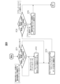
- FIG. 4 is a flowchart for explaining an example of processing in the first example of the take-out machine control program according to the present embodiment.
- FIG. 5 is a flowchart for explaining an example of the first process in the flowchart shown in FIG.
- FIG. 6 is a flowchart for explaining an example of the second process in the flowchart shown in FIG.
- FIG. 7 is a flowchart for explaining an example of the third process in the flowchart shown in FIG. 4.
- FIG. 8 is a flowchart for explaining an example of the fourth process in the flowchart shown in FIG.
- FIG. 9 is a flowchart for explaining an example of processing in the first modified example of the take-out machine control program according to the present embodiment.
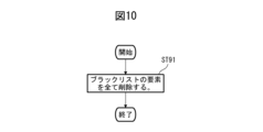
- FIG. 10 is a flowchart for explaining the main part of the process in the second modified example of the take-out machine control program according to the present embodiment.
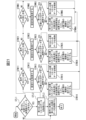
- FIG. 11 is a flowchart for explaining an example of processing in the second example of the take-out machine control program according to the present embodiment.
- FIG. 12 is a diagram showing an example of a list (take-out position list) in the industrial robot system shown in FIG. 2.
- FIG. 13 is a flowchart for explaining an example of the first process in the flowchart shown in FIG. 11.
- FIG. 11 is a flowchart for explaining an example of the first process in the flowchart shown in FIG. 11.
- FIG. 14 is a flowchart for explaining an example of the second process in the flowchart shown in FIG. 11.
- FIG. 15 is a flowchart for explaining an example of the third process in the flowchart shown in FIG. 11.
- FIG. 16 is a flowchart for explaining an example of the fourth process in the flowchart shown in FIG. 11.
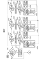
- FIG. 17 is a flowchart for explaining an example of processing in the third example of the take-out machine control program according to the present embodiment.
- FIG. 18 is a diagram showing another example of the list (take-out position list) in the industrial robot system shown in FIG. 2.
- FIG. 19 is a flowchart for explaining an example of the first process in the flowchart shown in FIG. 17.
- FIG. 19 is a flowchart for explaining an example of the first process in the flowchart shown in FIG. 17.
- FIG. 20 is a flowchart for explaining an example of the second process in the flowchart shown in FIG. 17.
- FIG. 21 is a flowchart for explaining an example of the third process in the flowchart shown in FIG. 17.
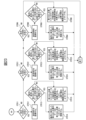
- FIG. 22 is a flowchart (Part 1) for explaining an example of the fourth process in the flowchart shown in FIG. 17.
- FIG. 23 is a flowchart (part 2) for explaining an example of the fourth process in the flowchart shown in FIG. 17.
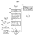
- FIG. 24 is a flowchart for explaining an example of the process of selecting data to be taken out from the take-out position list according to the priority in the take-out machine control program of the third embodiment shown in FIG.
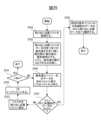
- FIG. 25 is a flowchart for explaining another example of the process of selecting data to be extracted from the extraction position list according to priority in the extraction machine control program of the third embodiment shown in FIG.
- FIG. 1 is a diagram schematically showing an industrial robot system as an example of a retrieval machine system according to the present embodiment.
- the take-out machine system according to the present embodiment can be applied to, for example, an industrial robot system that uses an industrial robot to take out workpieces that are placed randomly (stacked in bulk). It is not limited to. That is, the retrieval machine system according to the present embodiment is widely applicable not only to robot systems such as industrial robots and collaborative robots, but also to retrieval machine systems that have the function of retrieving various objects using various machines. Is possible.
- reference numeral 1 is an industrial robot (extraction machine)
- 2 is a robot control device (extraction machine control device)
- 3 is a 3D sensor (three-dimensional measuring instrument)
- 4 is a stored object
- 100 is an industrial robot system. (mechanical system)
- W indicates a workpiece (object).
- an industrial robot system 100 as an example of a retrieval machine system according to the present embodiment includes an industrial robot 1, a robot control device 2, and a 3D sensor 3.
- the industrial robot 1 is controlled by a robot control device 2, and picks up a plurality of workpieces W randomly placed in a storage object 4 by using a hand section (end effector: gripping section) 12 provided at the tip of an arm 11. It is designed to be taken out (grasped) one by one.
- the 3D sensor 3 is composed of, for example, a stereo camera, and is attached near the hand section 12. Images of the external shapes of the plurality of workpieces W in the container 4 captured by the 3D sensor 3 are output to the robot control device 2 . That is, the output of the 3D sensor 3 is input to the robot control device 2, where the position and orientation of the workpiece W is detected (calculated), and, for example, multiple takeout positions can be set for one workpiece W. be exposed.
- the hand unit 12 is, for example, a pneumatic gripper that grips the workpiece W using air pressure, and whether or not the hand unit 12 has successfully gripped (taken out) the workpiece W is determined by the measurement of the air pressure sensor 12a provided in the hand unit 12. This can be determined based on the results. Note that the determination as to whether or not the work W has been successfully taken out is not limited to the one based on the measurement results of the air pressure sensor 12a. It is also possible to make a determination based on the state etc.
- the 3D sensor 3 is attached near the moving hand part 12 of the industrial robot 1, but for example, it is fixed to the ceiling above the industrial robot 1, and the fixed 3D sensor 3
- the outer shapes of the plurality of works W within the storage object 4 may be measured (photographed).
- the 3D sensor 3 is not limited to a stereo camera, and various sensors can be used as long as the three-dimensional shapes of a plurality of works can be measured.
- FIG. 2 is a block diagram showing each function of the industrial robot system shown in FIG. 1.
- the robot control device 2 controls the industrial robot 1 to take out the workpiece W, etc., and includes a data import section 21, a data processing section 22, a list 23, and a take-out position selection section. 24 and a robot control section 25.
- the retrieval machine control program according to the present embodiment which will be described in detail later, is executed by, for example, an arithmetic processing unit configured of the data processing unit 22, the retrieval position selection unit 24, the robot control unit, etc. in the robot control device 2. .
- the list 23 is a memory (storage unit), and is used as a black list or an extraction position list, which will be described in detail later. That is, the list 23 can be applied, for example, as a black list in which a plurality of take-out positions that the industrial robot 1 is not allowed to access are stored. Furthermore, the list 23 can also be applied as a take-out position list, for example, in which an item of priority (take-out order) is further provided for each take-out position. Note that in the following description, for example, a description of a retrieval position that is not stored in the blacklist will be omitted because it is out of the subject of this embodiment.
- the data acquisition unit 21 acquires, for example, data on the external shapes of a plurality of works W that are stacked (disorderly placed) in the container 4 and measured by the 3D sensor 3.
- the data processing unit 22 receives and processes the data from the data importing unit 21, and associates data for controlling the industrial robot 1 to access the workpiece W with each retrieval position for each retrieval position. Store in list 23.
- a plurality of take-out positions are set for at least one work W to be taken out by the hand section 12.
- the take-out position selection unit 24 selects the take-out position of the work W to be taken out by the industrial robot 1 based on the output of the list 23, and the robot control unit 25 selects the take-out position of the workpiece W to be taken out by the industrial robot 1 based on the output of the take-out position selection unit 24.
- the workpiece W is taken out under control. That is, the take-out position selection unit 24 selects the take-out position of the work W to be taken out (accessed) by the industrial robot 1 based on the output of the list 23. Then, the robot control unit 25 controls the industrial robot 1 to access the take-out position selected by the take-out position selection unit 24, perform a take-out operation, and take out the workpiece W including the take-out position.
- FIG. 3 is a diagram showing an example of a list (black list) in the industrial robot system shown in FIG. It shows an example of a blacklist used in the processing of the embodiment.
- the blacklist 23 includes, for example, "work ID”, “take-out position ID”, “position/orientation (X, Y, Z, W, P, R)", “stay count”, and " It is classified by items such as "life count”.
- This blacklist is used for processing such as deleting the stored (written) takeout position from the blacklist when the takeout position moves due to a workpiece takeout operation, or when the workpiece takeout operation is performed a predetermined number of times. It is also used to carry out. This makes it possible to efficiently perform workpiece removal processing.
- Work ID is an identification number (IDentification) for each of the plurality of works W in the storage object 4
- Take-out position ID is an identification number for each of the plurality of take-out positions set for the work W. .
- the "work ID” is "3"
- the "take-out position ID” of "2" indicates the second take-out position
- the "take-out position ID” of "3" indicates the third take-out position.
- Position/orientation (X, Y, Z, W, P, R) is the three-dimensional position data (X, Y, Z) and orientation data (W, P, R) at the take-out position set for each workpiece W. ).
- the three-dimensional position data (X, Y, Z) indicates the distance (e.g., mm) from the reference point (origin: for example, the corner of the stored object), and the posture data (W, P, R) indicates each Indicates the rotation angle (e.g., degrees) about the axes (X-axis, Y-axis, Z-axis).
- the "stay count” is a count value that is increased according to the stay after being stored in the blacklist 23. Specifically, the "stay count” is incremented by "1" each time the pick-up position of an arbitrary workpiece W is stored in the blacklist 23, and when the pick-up position reaches a predetermined value (for example, "5"), The location is removed from the blacklist. Note that the extraction position deleted from the blacklist may be returned to a list (extraction position list) in which extraction positions that are not stored in the blacklist are stored, for example.
- the "life count” is a count value that is decreased according to the number of accesses after being stored in the blacklist 23. Specifically, the "life count” is set by “1" each time a workpiece W is accessed from a predetermined value (for example, "10") to the take-out position of any workpiece W stored in the blacklist 23.
- the extraction position that is decremented and becomes less than or equal to zero is deleted from the blacklist 23. Note that the extraction position deleted from the blacklist may be returned to a list (extraction position list) in which extraction positions that are not stored in the blacklist are stored, for example. Therefore, as will be described in detail later, the contents of the blacklist 23 will change depending on the operation (shifting operation, breaking operation) of the workpiece W by the extraction machine (industrial robot) 1, and the like.
- the data processing section 22 processes the data acquired by the data acquisition section 21, and the blacklist 23, the extraction position selection section 24, and the robot The operation of picking up the work W by the industrial robot 1 is controlled via the control unit 25 .
- the black list 23 is managed for each take-out position of the workpiece W.
- the first take-out position and the second take-out position are set for one workpiece W, if taking out is attempted at the first take-out position and fails, the first take-out position is stored (written) in the blacklist 23. Then, in subsequent retrieval accesses, the first retrieval position is excluded from retrieval targets (retrieval candidates) until a certain condition is met.
- the second take-out position set for the same workpiece W as the first take-out position stored in the black list 23 is not stored in the black list 23.
- the second retrieval position of the work W whose first retrieval position is stored in the blacklist is accessible without being excluded from the retrieval target, like other retrieval positions not stored in the blacklist.
- the robot control device 2 may check for interference, and regarding a take-out operation at a pick-up position where interference may occur, consider it as a failure before performing the pick-up operation and store the take-out position in the black list 23. good.
- the movement route to the extraction position includes a position outside the robot's operating range or a position of a singular point, Since the extraction position cannot be reached, it is preferable that such an extraction position is also stored in the blacklist.
- the application of the present embodiment is not limited to the operation of taking out the work W in a narrow sense, but also applies to operations after the taking out operation fails, such as shifting or breaking the work W, for example.
- the shifting operation is performed, for example, when the hand unit 12 of the industrial robot 1 accesses the take-out position set on the workpiece W and performs the take-out operation, but when the workpiece cannot be taken out because the grip is shallow, the hand unit This is an operation of moving the work W by 12.
- the breaking operation may be performed, for example, when the workpiece cannot be taken out by accessing all the takeout positions set for the workpiece W, by applying an external force to any workpiece W using the hand section 12 of the industrial robot 1 (workpiece (Press W) This is an action to break up the surrounding workpieces.
- the breaking operation is also normally performed by accessing one of the take-out positions set on the workpiece W.
- the retrieval machine system As described above, according to the retrieval machine system according to the present embodiment, it is possible to efficiently access the work W in which a plurality of retrieval positions are set. Regarding the application of this embodiment, it is not necessary to set a plurality of take-out positions for all the works W in the stored object 4, and only one take-out position is set for some of the works W. It is possible to apply even if
- FIG. 4 is a flowchart for explaining an example of processing in the first example of the take-out machine control program according to the present embodiment.
- a 3D sensor (3) detects a plurality of objects in the contained object (4).
- the external shape of the workpiece (W) is measured, and the process proceeds to step ST12, where the position and orientation (x, y, z, w, p, r) of each workpiece is detected (calculated), and the process proceeds to step ST13.
- step ST13 the take-out position for each workpiece is calculated, and the process proceeds to step ST14.
- step ST13 if possible, a plurality of take-out positions are calculated for one workpiece. Note that the take-out positions calculated in step ST13 do not need to be calculated (set) for each of two or more take-out positions for all the workpieces in the container; for example, for a work for which only one take-out position is set. may be included as described above.
- step ST14 it is determined (comparative determination) whether there is a blacklist (23) that overlaps with the detection result, and if it is determined that there is a blacklist (23) that overlaps with the detection result (YES), the process proceeds to step ST15.
- step ST15 blacklist information is inherited from the duplicate blacklist, the corresponding blacklist is deleted, and the process proceeds to step ST16 (second process Pb).
- step ST14 if it is determined in step ST14 that there is no blacklist that overlaps with the detection result (NO), the process directly proceeds to step ST16.
- steps ST14 and ST15 constitute a first process Pa. Note that an example of the first process Pa will be described in detail later with reference to FIG. 5.
- step ST16 the blacklist is updated, and the process proceeds to step ST17, where it is determined whether there are any detection results and extraction positions remaining that can be extracted.
- step ST17 if it is determined that there are remaining detection results and extraction positions that can be retrieved (YES), the process proceeds to step ST19, and if it is determined that there are no detection results and extraction positions that can be taken out (NO), the process proceeds to step ST18. Note that an example of the process of step ST16 (second process Pb) will be described in detail later with reference to FIG. 6.
- step ST18 it is determined whether or not the removal of the workpieces from the storage object has been completed, and if it is determined that the removal of the workpieces from the storage object has been completed (YES), the process ends. On the other hand, if it is determined in step ST18 that the removal of the workpieces in the stored object is not completed (NO), the process returns to step ST11, the 3D sensor measures the plurality of works in the stored object, and the above-described process is repeated.
- step ST19 the detection result to be extracted and the extraction position are determined, and the process proceeds to step ST20, where operations such as extraction, shifting, and collapse are performed, and the process further proceeds to step ST21.
- step ST21 it is determined whether or not the operation was successful. If it is determined that the operation is successful (YES), the process proceeds to step ST22 (third process Pc), and if it is determined that the operation is not successful (NO), step ST23 ( Proceed to fourth process Pd).
- step ST22 third process Pc
- step ST23 Proceed to fourth process Pd.
- FIG. 5 is a flowchart for explaining an example of the first process Pa (processing of steps ST14 and ST15) in the flowchart shown in FIG.
- This first process Pa is related to, for example, processing of a blacklist for other works moved by the take-out operation when the industrial robot 1 performs a take-out operation on a work in the stored object.
- step ST31 when the first process Pa starts (after calculating the take-out position for each workpiece in step ST13), it is determined in step ST31 whether there is a new unconfirmed detection result.
- step ST31 If it is determined in step ST31 that there are no new unconfirmed detection results (NO), the process proceeds to step ST34, in which all data in the blacklist with a deletion flag set is deleted from the blacklist, and the first process Pa is ended.
- step ST34 In step ST34, once all the data in the blacklist for which the deletion flag is set is deleted from the blacklist, the process proceeds to step ST16 (second process Pb) in FIG. 4.
- step ST31 determines whether there is a new unconfirmed detection result (YES). If it is determined in step ST31 that there is a new unconfirmed detection result (YES), the process proceeds to step ST32, where the position/orientation and extraction position of the detection result are acquired, and the process proceeds to step ST33. In step ST33, it is determined whether there is unconfirmed data in the blacklist. If it is determined that there is unconfirmed data in the blacklist (YES), the process proceeds to step ST35, and if it is determined that there is unconfirmed data in the blacklist (NO). Once determined, the process returns to step ST31.
- step ST35 the blacklist data is acquired, the process proceeds to step ST36, the detection result is compared with the position and orientation of the blacklist data, and the process further proceeds to step ST37 to determine whether there is overlap.
- the position and orientation (X, Y, Z, W, P, R) of the blacklist data described above may be, for example, only the position (X, Y, Z) of the blacklist data.
- step ST37 if it is determined that the position and orientation of the detection result and the blacklist data overlap (YES), the process proceeds to step ST38, and if it is determined that they do not overlap (NO), the process returns to step ST33.
- step ST38 a deletion flag is set on the blacklist data, and the process proceeds to step ST39, where the detection result and the position and orientation of the blacklist data extraction position are compared.
- the comparison of the position and orientation data (X, Y, Z, W, P, R) may be performed by comparing only the position data (X, Y, Z).
- posture data (W, P, R) is just one expression format; for example, it can be expressed in other expression formats such as rotation matrix, quaternion, rotation axis and rotation angle, or polar coordinates. There may be.
- the comparison of position and orientation data (X, Y, Z, W, P, R) may be performed by comparing only position data (X, Y, Z) or only (X, Y), as described later. The same applies to other processes, and this makes it possible to reduce the number of parameters to be compared.
- step ST40 it is determined (comparative judgment) whether or not there is an overlap. If it is determined that there is an overlap (YES), the process proceeds to step ST41, and if it is determined that there is no overlap (NO), the process proceeds to step ST33. Return to In step ST41, the extraction position of the detection result is added to the blacklist, data other than the work ID, extraction position ID, detection position, extraction position, and deletion flag of the compared blacklist data are copied, and the process returns to step ST33.
- the newly detected retrieval position when the information on the newly detected retrieval position based on the data from the sensor (the position and orientation of the detection result) overlaps the information on the retrieval position (position and orientation) that is already stored in the blacklist, the newly detected retrieval position Store the extraction position in the blacklist. Further, data other than the work ID, the extraction position ID, the detection position, the extraction position, and the deletion flag of the extraction position stored in the compared blacklist is copied (inherited). Then, the information about the extraction position stored in the duplicate blacklist is deleted.
- FIG. 5 is for explaining an example of the first processing Pa, and includes, for example, the error range (margin; threshold value) when determining duplication, and the influence of proximity to the extraction position added to the blacklist.
- error range margin; threshold value
- FIG. 5 is for explaining an example of the first processing Pa, and includes, for example, the error range (margin; threshold value) when determining duplication, and the influence of proximity to the extraction position added to the blacklist.
- Various settings can be made for the range that is considered to be affected. It goes without saying that when a workpiece is successfully taken out, all the takeout positions set for that workpiece are deleted from the list for taking out and the blacklist.
- FIG. 6 is a flowchart for explaining an example of the second process Pb in the flowchart shown in FIG. 4.
- step ST51 it is determined whether there is unupdated data in the blacklist.
- step ST52 if it is determined that there is unupdated data in the blacklist (YES), the process proceeds to step ST52, and if it is determined that there is no unupdated data in the blacklist (NO), the second process Pb is ended.
- the process proceeds to step ST17 in the flowchart of FIG. 4 described above.
- step ST52 the life count of the blacklist data is decreased by a predetermined value (for example, by "1"), and the process further proceeds to step ST53, where the stay count of the blacklist data is reduced to a predetermined value (for example, by "1"). Increase by ⁇ 1'').
- the life count can be set to "10" as an initial value (when stored in the blacklist), and the stay count can be set to "1" as an initial value.
- step ST54 it is determined whether the life count ⁇ 0. Note that determining whether the life count ⁇ 0 is determined by, for example, if the predetermined value to be decremented in step ST52 is set to "3" and the previous life count is "1", there is a possibility that the life count becomes negative. This is because there is.
- the value by which the life count is decreased in step ST52 is not a uniform fixed value, but may be weighted depending on the distance from the extraction position accessed to perform the extraction operation, for example. For example, for a retrieval position that is closest to the accessed retrieval position, the life count is decreased by "3", and for a retrieval position that is a certain distance away from the accessed retrieval position, the life count is reduced to "1". It is also possible to reduce the amount by just . In this way, a weight is set for the value that decreases the life count set at the first take-out position based on the distance from the second take-out position that is related to (fails in) the take-out operation of the object. That is, it is also possible to set a weight based on a predetermined condition (third condition) for the value that decreases the life count set at the extraction position.
- a workpiece whose takeout position is set very close to the accessed takeout position is more likely to move than a workpiece that is a certain distance away (for example, several cm). Therefore, it is preferable to greatly reduce the life count. Furthermore, it is also possible to give weight to the value that decreases the life count depending on the type of access to the workpiece, such as whether it is a take-out operation or a shifting or breaking operation. For example, when the access to the workpiece is a breaking operation, the value for decreasing the life count is set to a large value, and when the access to the workpiece is a take-out operation or a shifting operation, the value for decreasing the life count is set to a small value.
- step ST54 if it is determined that the life count ⁇ 0 (YES), the process proceeds to step ST56, and if it is determined that the life count ⁇ 0 is not (NO), the process proceeds to step ST55.
- step ST55 it is determined whether the stay count ⁇ a predetermined value (for example, “5”). In step ST55, if it is determined that the stay count is greater than or equal to the predetermined value (YES), the process proceeds to step ST56, and if it is determined that the stay count is not greater than or equal to the predetermined value (NO), the process is returned to step ST51 and the same process is performed. repeat.
- a predetermined value for example, “5”.
- a stay count is set for the first take-out position of the workpiece stored in the blacklist, and a stay count is set for the first take-out position of the workpiece stored in the blacklist, and the stay count is set within a predetermined range (around ) includes the first retrieval position, the stay count of the first retrieval position is increased.
- the stay count of the first extraction position reaches a predetermined value (for example, "5") or more, the first extraction position is deleted from the blacklist. That is, a stay count is set for the take-out position of the object stored in the blacklist, and the stay count set for the take-out position is increased based on a predetermined condition (first condition).
- the extraction position of the object stored in the blacklist is deleted from the blacklist.
- the first retrieval position becomes an access target as a retrieval position that is not stored in the blacklist.
- a life count is set for the first take-out position of the workpieces stored in the blacklist, and the life count of the first take-out position is decreased based on the number of times a given workpiece take-out operation is performed. Then, when the life count of the first extraction position becomes zero or less, the first extraction position is deleted from the blacklist. That is, a life count is set for the extraction position of the object stored in the blacklist, and the life count set for the extraction position is decreased based on a predetermined condition (second condition). Then, when the life count set at the extraction position becomes zero or less, the extraction position of the object stored in the blacklist is deleted from the blacklist.
- the first retrieval position becomes an access target as a retrieval position that is not stored in the blacklist.
- the initial values of the life count and the stay count, the values to be decreased/increased, etc. can be changed and modified in various ways depending on the specifications and requirements of the mechanical system to which this embodiment is applied.
- FIG. 7 is a flowchart for explaining an example of the third process Pc in the flowchart shown in FIG. 4.
- step ST61 settings (predetermined settings) are acquired, and processing is performed according to the acquired settings.
- step ST61 if it is determined that blacklist data that overlaps with the detection result of the motion extraction position is to be set (leftward) and all blacklist data is to be set (downward), the process advances to step ST62. Note that if it is determined in step ST61 that nothing is to be done (toward the right), the process directly proceeds to step ST63.
- step ST62 the life count is decreased by a predetermined value, and the process further proceeds to step ST63.
- the initial value of the life count and the value by which the life count is decreased can be changed and modified in various ways depending on the specifications and requirements of the mechanical system to which this embodiment is applied.
- step ST63 all data on the blacklist whose life count is less than or equal to zero is deleted, and the third process Pc is ended. After completing the third process Pc, the process proceeds to step ST17 in the flowchart of FIG. 4 described above.
- FIG. 8 is a flowchart for explaining an example of the fourth process Pd in the flowchart shown in FIG. 4.
- the fourth process Pd in the flowchart of FIG. 4 starts, settings are acquired in step ST71, and processing is performed according to the acquired settings.
- step ST71 if it is determined that blacklist data that overlaps with the detection result of the motion extraction position is to be set (leftward) and all blacklist data is to be set (downward), the process advances to step ST72. Note that if it is determined in step ST71 that nothing is to be done (to the right), the process directly proceeds to step ST73.
- step ST72 the life count is decreased by a predetermined value, and the process further proceeds to step ST73.
- the initial value of the life count and the value by which the life count is decreased can be changed and modified in various ways depending on the specifications and requirements of the mechanical system to which this embodiment is applied.
- step ST73 all data on the blacklist whose life count is less than or equal to zero is deleted, the process proceeds to step ST74, settings are acquired, and processing is performed according to the acquired settings.
- step ST74 If it is determined in step ST74 that the motion should be added to the blacklist (downwards), the process proceeds to step ST75, where the extraction position of the motion is added to the blacklist and the fourth process Pd is ended, and it is not added to the blacklist (rightward). If it is determined that this is the case, the fourth process Pd is immediately terminated. That is, if it is determined in step ST74 not to add to the blacklist and the process in step ST75 is completed, the process advances to step ST17 in the flowchart of FIG. 4 described above.
- FIG. 9 is a flowchart for explaining an example of processing in the first modification of the take-out machine control program according to the present embodiment. As is clear from the comparison between FIG. 9 and FIG. This is to add. Note that the processing in other steps ST11 to ST23 is the same as that described with reference to FIG. 4, and their description will be omitted.
- step ST81 it is determined whether there is a take-out position that does not interfere. That is, in step ST81, for example, it is determined whether there is a take-out position where the hand part 12 of the industrial robot 1 does not interfere with the side surface of the stored object 4, etc., and if it is determined that there is no take-out position where it does not interfere (NO), step ST81 is performed. Proceed to ST23. On the other hand, if it is determined in step ST81 that there is a take-out position that does not interfere (YES), the process proceeds to step ST20, where operations such as take-out, shifting, and breaking are performed.
- the process in step ST81 is performed when the robot reaches the take-out position, for example, when it is outside the operating range of the robot or when a singular point of the robot is on the movement route to the take-out position.
- This also includes determination processing when it is not possible.
- the corresponding extraction position may be added to the blacklist. That is, for example, work related to automatic route generation can also be added to the blacklist.
- automatic path generation is, for example, a path that allows the robot control device to move from the robot's current position to the take-out position (avoiding interference between the robot and peripheral equipment or workpieces, outside the robot's operating range, singularities of the robot, etc.).
- FIG. 10 is a flowchart for explaining the main part of the process in the second modified example of the take-out machine control program according to the present embodiment, and explains another example of the second process Pb in the flowchart shown in FIG. 4 described above. It is for the purpose of
- step ST91 when the second process Pb in the flowchart of FIG. 4 starts, all elements of the blacklist are deleted in step ST91, and the second process Pb is ended.
- the fact that there are no duplicates in the blacklist with new detection results after measurement means that data does not exist in the position and orientation when it was stored in the blacklist due to reasons such as the load collapsing or the workpiece being taken out. This is because it shows. Therefore, in such a case, it is preferable to delete all the data on the blacklist, which makes it possible to take out the object even more efficiently.
- the second modification shown in FIG. 10 includes not only the take-out machine control program of the first embodiment described with reference to FIGS. 4 to 8, but also the first modification shown with reference to FIG. It can also be applied as the second process Pb in the take-out machine control program.
- the first modification shown in FIG. 9, that is, the modification in which the process of step ST81 is added between steps ST19 and ST20, is applicable to the take-out machine control program of the second and third embodiments described later. can also be applied.
- the second modification shown in FIG. 10 that is, the process of deleting all the elements of the blacklist in step ST91 as the second process Pb, can be applied to the extraction machine control program of the second embodiment described later. You can also do it. That is, even if the priority of the data of all the extraction positions in the extraction position list is returned to a predetermined value (for example, the initial value) as the second process Pb' in the extraction machine control program of the second embodiment described later, good.
- the black list 23 determines whether the take-out position is a target for taking out the workpiece W by the robot 1, based on whether the take-out position is stored or not. It is used for binary control such as whether or not to do so.
- the priority (weight) of taking out is assigned to each taking out position, instead of using the blacklist 23 to perform either-or-nothing control. Based on the priority, the order of the take-off positions from which the work W is taken out by the robot 1 is controlled.
- the list 23 in FIG. 2 described above will be used, for example, as an extraction position list to which a new priority item is added.
- the above-mentioned processing of the life count and stay count is performed in the same manner as in the above-mentioned first embodiment, but for example, when the life count becomes zero or less, the data in the blacklist 23 is Rather than deleting (erasing) data and treating it as an accessible retrieval position that is not stored in the blacklist 23, the priority of the data at the retrieval position whose life count has become zero or less is set to a predetermined value (for example, By returning it to the initial value "100"), it will be processed as an accessible extraction position.
- a predetermined value for example, By returning it to the initial value "100
- FIG. 11 is a flowchart for explaining an example of processing in the second example of the take-out machine control program according to the present embodiment
- FIG. 12 is a list (take-out position list) in the industrial robot system shown in FIG. It is a figure showing an example. Note that the processes in steps ST11 to ST13 and ST18 to ST21 in FIG. 11 are substantially the same as those described with reference to FIG. 4, so a detailed explanation of these processes will be omitted. Furthermore, as is clear from the comparison between FIG. 12 and FIG. This corresponds to the addition of a priority item indicated by a value of ⁇ 100''.
- the priority is an index when selecting each extraction position from the extraction position list 23, and it is sufficient to identify the priority order, so it is not limited to integers or real numbers, and if the size relationship can be defined, various It may be a symbol etc.
- step ST13 the position and orientation of each workpiece detected in step ST12 (x, y, z, w, p, After calculating the take-out position for each work from r), the process proceeds to step ST84.
- step ST13 if a plurality of takeout positions can be set for one workpiece depending on the shape and size of the workpiece W, the plurality of takeout positions are calculated. Furthermore, the take-out positions calculated in step ST13 do not need to be calculated for each of two or more take-out positions for all the works in the storage object. Needless to say, you can leave it alone.
- step ST84 it is determined (comparative judgment) whether or not there is a take-out position whose priority level is lowered and which overlaps with the detection result, and it is determined that there is a take-out position whose priority level is lowered which overlaps with the detection result (YES). Once determined, the process advances to step ST85. In step ST85, the information is taken over from the overlapping take-out position with lower priority, the corresponding take-over source take-out position is deleted, and the process proceeds to step ST86 (second process Pb').
- step ST84 determines whether there is no retrieval position with lowered priority that overlaps with the detection result (NO)
- steps ST84 and ST85 constitute a first process Pa'.
- the data of the retrieval position whose priority has been lowered is updated, and the process proceeds to step ST17, where it is determined whether there remain detection results and retrieval positions that can be retrieved.
- step ST86 second process Pb'
- step ST21 it is determined whether the operation was successful or not. If it is determined that the operation is successful (YES), the process proceeds to step ST92 (third process Pc'), and if it is determined that the operation is not successful (NO), step ST93 Proceed to (fourth process Pd').
- step ST92 third process Pc'
- step ST93 fourth process Pd'
- FIG. 13 is a flowchart for explaining an example of the first process Pa′ (processing of steps ST84 and ST85) in the flowchart shown in FIG.
- the first process Pa' starts (after calculating the take-out position for each work in step ST13)
- step STA4 if all the extraction positions with lower priorities for which deletion flags are set are deleted, the process proceeds to step ST86 (second process Pb') in FIG. 11.
- step ST31 determines whether or not there is unconfirmed detection result (YES)
- step ST32 determines whether or not there is unconfirmed data at the retrieval position whose priority has been lowered
- step STA5 it is determined whether or not there is unconfirmed data at the extraction position where the priority has been lowered (NO)
- the process returns to step ST31.
- step STA5 the data of the take-out position whose priority has been lowered is acquired, and the process proceeds to step STA6, where the detection result is compared with the position and orientation of the workpiece at the take-out position whose priority has been lowered, and the process further proceeds to step ST37. to determine whether there are duplicates.
- the position/orientation (X, Y, Z, W, P, R) of the workpiece at the takeout position whose priority level has been lowered is, for example, the position (X, The fact that only Y, Z) can be used is the same as described with reference to FIG.
- step ST37 if it is determined that the detection result and the position and orientation of the workpiece at the take-out position whose priority has been lowered overlap (YES), the process proceeds to step STA8, and if it is determined that they do not overlap (NO), step STA3 Return to In step STA8, a deletion flag is set for the data at the retrieval position whose priority has been lowered, and the process proceeds to step STA9, where the detection result and the position and orientation of the retrieval position of the data at the retrieval position whose priority has been lowered are compared. .
- the comparison of the position and orientation data may be a comparison of only the position data (X, Y, Z).
- the pose data (W, P, R) is just one representation format; for example, it can be expressed in other representation formats such as rotation matrix, quaternion, rotation axis and rotation angle, or polar coordinates. There may be.
- the comparison of position and orientation data (X, Y, Z, W, P, R) may be performed by comparing only position data (X, Y, Z) or only (X, Y). This makes it possible to reduce the number of parameters to be compared.
- step ST40 it is determined whether or not there is an overlap. If it is determined that there is an overlap (YES), the process proceeds to step STB1, and if it is determined that there is no overlap (NO), the process returns to step STA3.
- step STB1 data other than the work ID, extraction position ID, detection position, extraction position, and deletion flag of the data of the extraction position whose priority level has been lowered is copied to the extraction position data of the detection result, and in step STA3 Return to
- FIG. 14 is a flowchart for explaining an example of the second process Pb' in the flowchart shown in FIG. 11.
- step STC1 it is determined whether or not there is unupdated data at a retrieval position whose priority has been lowered. If it is determined in step STC1 that there is unupdated data at the retrieval position whose priority has been lowered (YES), the process proceeds to step STC2, where it is determined that there is no unupdated data at the retrieval position whose priority has been lowered (NO). Once determined, the second process Pb' is ended. When the second process Pb' is finished, the process proceeds to step ST17 in the flowchart of FIG. 11 described above.
- step STC2 the life count of the data at the retrieval position whose priority has been lowered is decreased by a predetermined value (for example, by "1"), and the process further proceeds to step STC3, where the life count of the data at the retrieval position whose priority has been lowered is decreased.
- Increase the data stay count by a predetermined value for example, by "1”
- the life count can be set to "10" as an initial value
- the stay count can be set to "1" as an initial value.
- step ST54 it is determined whether the life count ⁇ 0.
- the value by which the life count is decreased in step STC2 is not a uniform fixed value, but may be weighted depending on the distance from the extraction position accessed to perform the extraction operation, for example. For example, for a retrieval position that is closest to the accessed retrieval position, the life count is decreased by "3", and for a retrieval position that is a certain distance away from the accessed retrieval position, the life count is reduced to "1". It is also possible to reduce the amount by just . In this way, a weight is set for the value that decreases the life count set at the first retrieval position based on the distance from the second retrieval position related to the object retrieval operation. That is, it is also possible to set a weight based on a predetermined condition (third condition) for the value that decreases the life count set at the extraction position.
- a predetermined condition third condition
- a workpiece whose takeout position is set very close to the accessed takeout position is more likely to move than a workpiece that is a certain distance away (for example, several cm). Therefore, it is preferable to greatly reduce the life count. Furthermore, it is also possible to give weight to the value that decreases the life count depending on the type of access to the workpiece, such as whether it is a take-out operation or a shifting or breaking operation. For example, when the access to the workpiece is a breaking operation, the value for decreasing the life count is set to a large value, and when the access to the workpiece is a take-out operation or a shifting operation, the value for decreasing the life count is set to a small value.
- step ST54 If it is determined in step ST54 that the life count ⁇ 0 (YES), the process proceeds to step STC6, and the priority of the data at the retrieval position whose priority has decreased is set to a predetermined value (for example, the initial value "100"). return. On the other hand, if it is determined in step ST54 that the life count is not 0 (NO), the process proceeds to step ST55, and it is determined whether the stay count is ⁇ a predetermined value (for example, "5"). If it is determined in step ST55 that the stay count is greater than or equal to the predetermined value (YES), the process proceeds to step STC6, where the priority of the data at the retrieval position whose priority has decreased is set to a predetermined value (for example, the initial value). return. On the other hand, if it is determined in step ST55 that the stay count is not the predetermined value (NO), the process returns to step STC1 and the same process is repeated.
- a predetermined value for example, the initial value "100"
- a stay count is set for the first take-out position of the workpiece whose priority has decreased, and the first take-out position is within a predetermined range from the second take-out position related to the object take-out operation. If included, increases the dwell count of the first retrieval position. Then, when the stay count of the first pick-up position reaches a predetermined value (for example, "5") or more, the priority of the data at the first pick-up position of the work whose priority has been lowered is returned to the predetermined value. . That is, a stay count is set for the take-out position of the work whose priority has decreased, and the stay count set for the take-out position is increased based on a predetermined condition (first condition).
- a predetermined condition for example, "5"
- the priority of the data at the take-out position of the work whose priority has been lowered is returned to a predetermined value.
- the first take-out position becomes an access target as a take-out position for a workpiece with a high priority.
- a life count is set for the first take-out position of the work whose priority has been lowered, and the life count of the first take-out position is decreased based on the number of times the take-out operation of a given work is performed. Then, when the life count at the first take-out position becomes zero or less, the priority of the data at the take-out position of the work whose priority has been lowered is returned to a predetermined value. That is, a life count is set for the take-out position of the work whose priority has decreased, and the life count set for the take-out position is decreased based on a predetermined condition (second condition).
- the priority of the data at the take-out position of the work whose priority has been lowered is returned to a predetermined value.
- the first take-out position becomes an access target as a take-out position for a workpiece with a high priority.
- the second modification described with reference to FIG. 10 can be applied as the second process Pb' in the flowchart of FIG. 11. That is, as the second process Pb' in the flowchart of FIG. 11, if there is no new detection result that overlaps with the work of the data at the take-out position whose priority has been lowered, the data at the take-out position whose priority has been lowered is deleted. You may. For example, if there is no duplicate data for the take-out position whose priority has been lowered due to new detection results after measurement, this means that when the priority is lowered due to a load collapse or a workpiece being taken out, etc. This is because it indicates that the workpiece no longer exists in the position and orientation.
- FIG. 15 is a flowchart for explaining an example of the third process Pc' in the flowchart shown in FIG. 11.
- step ST61 settings (predetermined settings) are acquired, and processing is performed according to the acquired settings.
- step ST61 the data of the take-out position whose priority has been lowered overlaps with the detection result of the pick-up position of the operation is set (leftward), and the data of the take-out position of all the workpieces whose priority has been lowered is set. If it is determined to be (downward), the process advances to step STD2. Note that if it is determined in step ST61 that nothing is to be done (to the right), the process directly proceeds to step STD3.
- step STD2 the life count is decreased by a predetermined value, and the process further proceeds to step STD3.
- the initial value of the life count and the value by which the life count is decreased can be changed and modified in various ways depending on the specifications and requirements of the mechanical system to which this embodiment is applied.
- step STD3 the priority of the data at the take-out position of the work whose life count is less than zero and whose priority has decreased is returned to a predetermined value (for example, the initial value "100"), and the third process Pc' is terminated. do.
- the process proceeds to step ST17 in the flowchart of FIG. 11 described above.
- FIG. 16 is a flowchart for explaining an example of the fourth process Pd' in the flowchart shown in FIG. 11.
- the fourth process Pd' in the flowchart of FIG. 11 starts, settings are acquired in step ST71, and processing is performed according to the acquired settings.
- step ST71 the data of the take-out position whose priority is lowered and overlaps with the detection result of the pick-up position of the operation is set (leftward), and the data of the take-out position of all the workpieces whose priority is lowered is set. If it is determined to be (downward), the process advances to step STE2. Note that if it is determined in step ST71 that nothing is to be done (toward the right), the process directly proceeds to step STE3.
- step STE2 the life count is decreased by a predetermined value, and the process further proceeds to step STE3.
- the initial value of the life count and the value by which the life count is decreased can be changed and modified in various ways depending on the specifications and requirements of the mechanical system to which this embodiment is applied. be.
- step STE3 the priority of the data of the take-out position of the work whose life count is below zero and whose priority has decreased is returned to a predetermined value (for example, the initial value), and the process proceeds to step ST74 to obtain the settings. , perform processing according to the acquired settings.
- step ST74 if it is determined that the priority is to be lowered by a predetermined value (downward), the process proceeds to step STE5, the priority of the action extraction position is lowered by a predetermined value, and the fourth process Pd' is ended, and the priority is not lowered. (To the right), the fourth process Pd' is immediately terminated. That is, if it is determined in step ST74 that the priority is not to be lowered and the process in step STE5 is completed, the process proceeds to step ST17 in the flowchart of FIG. 11 described above.
- a priority item is added to the blacklist of the first embodiment, and the priority Based on this, the next extraction position to be accessed can be selected.
- FIG. 17 is a flowchart for explaining an example of processing in the third example of the take-out machine control program according to the present embodiment
- FIG. 18 is a list (take-out position list) in the industrial robot system shown in FIG. It is a figure showing other examples. Note that the processes in steps ST11 to ST13 and ST18 to ST21 in FIG. 17 are substantially the same as those described with reference to FIG. 4, so a detailed explanation of these processes will be omitted. Furthermore, as is clear from a comparison between FIG. 18 and FIG.
- the take-out position list 23 used in the take-out machine control program of the third embodiment deletes the stay count and life count items in FIG. It is integrated into priority items. That is, the data processing unit 22 integrates the stay count processing and life count processing in the extraction machine control program of the second embodiment into the priority processing.
- step ST13 the take-out position of each workpiece is calculated from the position and orientation (x, y, z, w, p, r) of each workpiece detected in step ST12, and then in step STF8. , set the priority to the extraction position. Furthermore, the process proceeds to step STF4, and it is determined whether or not there is an extraction position in the list that overlaps with the detection result.
- step ST13 if multiple take-out positions can be set for one workpiece depending on the shape and size of the workpiece W, these multiple take-out positions are calculated, and further, in step STF8, , a priority is set for each extraction position. Furthermore, the take-out positions calculated in step ST13 do not need to be calculated for each of two or more take-out positions for all the works in the storage object. It is the same as mentioned above.
- step STF4 determines whether or not selectable data remains in the extraction position list.
- steps STF4 and STF5 constitute a first process Pa''. An example of the first process Pa" will be described later in detail with reference to FIG. 19, and an example of the second process Pb" will be described later in detail with reference to FIG. 20.
- step STF7 if it is determined that there is selectable data remaining in the extraction position list (YES), the process proceeds to step ST19, and if it is determined that there is no selectable data remaining in the extraction position list (NO), the process proceeds to step ST18. move on.
- step ST19 the detection result and the extraction position to be extracted are determined, and the process proceeds to step STF1, where it is confirmed whether interference can be avoided and whether it can be reached.
- step STF1 it is confirmed whether interference can be avoided and whether it can be reached.
- step STF2 it is possible to reach the take-out position without interference within the tolerance set for the industrial robot's posture and peripheral equipment relative to the take-out position. This is done by recalculating whether or not. Then, proceeding to step STF2, it is determined whether there is interference or unreachability.
- step STF2 If it is determined in step STF2 that there will be interference or that it is unreachable (YES), the process proceeds to step STF3, where a take-out position that can be reached without interference is calculated within a set range from the take-out position, and the process proceeds to step STF9.
- step STF2 determines whether the operation was successful or not. If it is determined that the operation was successful (YES), the process proceeds to step STG2 (third process Pc''), and if it is determined that the operation has failed (NO), step STG3 Proceed to (fourth process Pd'').
- step STF9 it is determined whether there is a take-out position that can be reached without interference. If it is determined that there is a take-out position that can be reached (YES), the process proceeds to step ST20, and if there is no take-out position that can be reached (NO). ), the process advances to step STF7.
- An example of the process in step STG2 (third process Pc") will be described later in detail with reference to FIG. 21, and an example of the process in step STG3 (fourth process Pd”) will be described later in FIG. This will be explained in detail with reference to 23.
- FIG. 19 is a flowchart for explaining an example of the first process Pa" (processing of steps STF4 and STF5) in the flowchart shown in FIG. 17.
- step ST31 it is determined whether there is a new unconfirmed detection result. If it is determined in step ST31 that there are no new unconfirmed detection results (NO), the process proceeds to step STH4, in which all data in the extraction position list for which the deletion flag is set is deleted, and the first process Pa'' is terminated.
- step STH4 after all data in the extraction position list for which the deletion flag is set is deleted, the process proceeds to step STF6 (second process Pb'') in FIG.
- step ST31 determines whether there is a new unconfirmed detection result (YES). If it is determined in step ST31 that there is a new unconfirmed detection result (YES), the process proceeds to step ST32, where the position/orientation and extraction position of the detection result are acquired, and the process proceeds to step STH3. In step STH3, it is determined whether there is unconfirmed data in the data in the extraction position list. If it is determined that there is unconfirmed data (YES), the process proceeds to step STH5, and if it is determined that there is no unconfirmed data (NO), Return to step ST31.
- step STH5 the data in the take-out position list is acquired, and the process proceeds to step STH6, where the detection result and the workpiece position/orientation in the data in the take-out position list are compared, and the process proceeds to step ST37, in which it is determined whether there is any overlap. judge.
- the position and orientation of the workpiece (X, Y, Z, W, P, R) in the above-mentioned extraction position list data is, for example, only the position (X, Y, Z) of the workpiece in the extraction position data. What can be done is the same as in the first and second embodiments described above.
- step ST37 if it is determined that the position and orientation of the workpiece in the detection result and the data in the extraction position list overlap (YES), the process proceeds to step STH8, and if it is determined that they do not overlap (NO), the process returns to step STH3.
- step STH8 a deletion flag is set for the data in the extraction position list, and the process proceeds to step STH9, where the detection result is compared with the position and orientation of the extraction position of the data in the extraction position list, and the process proceeds to step ST40.
- step ST40 it is determined whether or not there is overlap. If it is determined that there is overlap (YES), the process proceeds to step STJ1, and if it is determined that there is no overlap (NO), the process returns to step STH3.
- step STJ1 data other than the work ID, extracting position ID, detected position, extracting position, and deletion flag of the data in the compared extracting position list is copied to the extracting position data of the detection result, and the process returns to step STH3.
- FIG. 20 is a flowchart for explaining an example of the second process Pb" in the flowchart shown in FIG. 17.
- the second process Pb in the flowchart shown in FIG. , it is determined whether there is unupdated data in the retrieval position list. If it is determined in step STK1 that there is unupdated data in the take-out position list (YES), the process proceeds to step STK2, where data in the take-out position list is acquired, and the process proceeds to step STK3. On the other hand, in step STK1, if it is determined that there is no unupdated data in the extraction position list (NO), the second process Pb" is terminated. Then, when the second process Pb" is terminated, the flowchart of FIG. The process will proceed to step STF7.
- step STK3 the priority of the data in the extraction position list is increased by a predetermined value. However, do not exceed the upper limit. That is, in step STK3, if there is unupdated data in the extraction position list, the priority of that data is increased by a predetermined value (for example, by "10"), but the priority is increased by an upper limit value (for example, by the initial value of "100"). ), and return to step STK1.
- a predetermined value for example, by "10"
- an upper limit value for example, by the initial value of "100”
- FIG. 21 is a flowchart for explaining an example of the third process Pc'' in the flowchart shown in FIG. 17.
- the third process Pc'' in the flowchart shown in FIG. it is determined whether there is unupdated data in the retrieval position list. If it is determined in step STL1 that there is unupdated data in the extraction position list (YES), the process proceeds to step STL2, where data in the extraction position list is acquired, and the process proceeds to step STM11. On the other hand, if it is determined in step STL1 that there is no unupdated data in the extraction position list (NO), the process proceeds to step STL3, deletes the data of the extraction position used in the operation, and ends the third process Pc''. When the third process Pc'' is completed, the process proceeds to step STF7 in the flowchart of FIG. 17 described above.
- steps STM11 to STM15, STM21 to STM25, ..., STMN1 to STMN5 perform similar processing for the respective conditions (settings) C1, C2, ..., CN. It has become. Therefore, in the following description, the processing for condition C1 (steps STM11 to STM15) will be explained, but the same processing will be performed for steps STM21 to STM25, ..., STMN1 to STMN5, except that the target conditions are different. become.
- step STM11 it is determined whether or not the unupdated data acquired from the extraction position list matches the condition C1. If it is determined that C1 is matched (YES), the process proceeds to step STM12, and if it is determined that the unupdated data obtained from the extraction position list matches the condition C1 (YES), the process proceeds to step STM12. If the determination is NO, the process advances to step STM21. Here, if it does not match C1 in step STM11, it is determined whether it matches C2 in step STM21, the same process is repeated, and it is determined whether or not it matches CN in step STMN1. Processing for conditions C1 to CN will be performed.
- step STM12 the setting C1 is acquired, and the process proceeds to step STM13, where it is determined whether the data in the extraction position list is to be deleted.
- step STM13 if it is determined that the data in the extraction position list is not to be deleted (NO), the process proceeds to step STM14, and if it is determined that the data in the extraction position list is to be deleted (YES), the process proceeds to step STM15.
- step STM14 a predetermined value C1 is added to the priority of the data in the extraction position list, and the process returns to step STL1.
- the priority addition process in step STM14 is made so as not to exceed the upper and lower limits.
- step STM15 the data in the extraction position list is deleted, and the process returns to step STL1. Note that STM21 to STM25, . . . , STMN1 to STMN5 are the same as the processing of STM11 to STM15, except that the target conditions C2, .
- the priority of the data in the take-out position list is adjusted according to various conditions C (C1, C2,...,CN), It is possible to control the extraction position that the industrial robot accesses.
- the conditions C may be, for example, the following.Note that the conditions C are limited to, for example, those listed below. Needless to say, any combination of these and various other possible changes and modifications are possible.
- C means that the position of the workpiece of the data in the extraction position list and the data of the extraction position used in the operation is within a predetermined distance, or that the extraction position of the data in the extraction position list and the extraction position used in the operation are There is a condition that the data extraction position is within a predetermined distance. Further, as C, there are also conditions such as no condition (applicable in any case), when the operation is a break, when the operation is a take-out, or when the operation is a shift.
- the position of the work of the data in the extraction position list and the work of the extraction position data used for the operation is within a predetermined distance, or if the operation is a collapse.
- the condition may be that the data retrieval position in the retrieval position list and the data retrieval position of the retrieval position used in the operation are within a predetermined distance.
- the operation is retrieval
- there is a condition that the position of the work of data in the retrieval position list and the work of the retrieval position data used for the operation is within a predetermined distance, or if the operation is retrieval.
- Another possible condition is that the data retrieval position in the retrieval position list and the data retrieval position of the retrieval position used in the operation are within a predetermined distance.
- the condition may be such that the data retrieval position in the retrieval position list and the data retrieval position of the retrieval position used in the operation are within a predetermined distance.
- the condition that the data retrieval position of the retrieval position used for the operation is within a predetermined range from a predetermined position, or the retrieval position used for the operation
- a possible condition is that the data retrieval position is within a predetermined range from the wall of the container.
- the condition that the data retrieval position of the retrieval position used for the operation is within a predetermined range from the top of the container, or the retrieval position used for the operation The condition may be such that the data retrieval position is within a predetermined range from the bottom of the container.
- each setting C (C1, C2, ..., CN)
- delete the data in the corresponding extraction position list or change the priority by a predetermined value C1, C2, ..., CN.
- the contents of each of the settings C1, C2, . . . , CN may change depending on predetermined conditions. That is, examples of the contents changing depending on predetermined conditions include, for example, the processing of the take-out machine control program of the first embodiment described with reference to FIGS. An example of this is to change the contents of the settings C1, C2, .
- each of the predetermined values C1, C2, ..., CN can be, for example, a value such as "-100", "-20", “0", "10", "100”, etc. It is also possible to set variables corresponding to the distance from the take-out position used in the above to the predetermined values C1, C2, . . . , CN. Further, each of the predetermined values C1, C2, . . . , CN can be changed depending on predetermined conditions. That is, examples of values changing depending on predetermined conditions include, for example, the processing of the take-out machine control program of the first embodiment described with reference to FIGS. An example of this is to change the values of the predetermined values C1, C2, .
- step STP1 it is determined whether there is any unupdated data in the extraction position list. If it is determined in step STP1 that there is unupdated data in the extraction position list (YES), the process proceeds to step STP2, where the data in the extraction position list is acquired, and the process proceeds to step STQ11. On the other hand, if it is determined in step STP1 that there is no unupdated data in the extraction position list (NO), the process advances to step STR11.
- steps STQ11 to STQ15, STQ21 to STQ25, ..., STQN1 to STQN5 perform similar processing for the respective conditions (settings) D1, D2, ..., DN. It is supposed to be done. Furthermore, steps STR11 to STR15, STR21 to STR25, . . . , STRN1 to STRN5 perform similar processing for the respective conditions DD1, DD2, .
- processing for condition D1 steps STQ11 to STQ15
- processing for condition DD1 steps STQ11 to STR15
- steps STQ21 to STQ25, ..., STQN1 to STQN5 and steps STR21 to STR25, ... , STRN1 to STRQN5 steps STQ21 to STQ25, ... , STRN1 to STRQN5
- steps STQ21 to STQ25, ..., STQN1 to STQN5 steps STR21 to STR25, ... , STRN1 to STRQN5
- step STQ11 it is determined whether or not the unupdated data acquired from the extraction position list matches the condition D1. If it is determined that D1 is matched (YES), the process proceeds to step STQ12, and if it is determined that the unupdated data obtained from the extraction position list does not match D1 ( If the determination is NO, the process advances to step STQ21.
- step STQ11 it is determined whether it matches D2 in step STQ21, the same process is repeated, and it is determined whether it matches DN in step STQN1. The processing for the conditions D1 to DN will be performed.
- step STQ12 the setting D1 is obtained, and the process proceeds to step STQ13, where it is determined whether the data in the extraction position list is to be deleted. If it is determined in step STQ13 that the data in the extraction position list is not to be deleted (NO), the process proceeds to step STQ14, and if it is determined that the data in the extraction position list is to be deleted (YES), the process proceeds to step STQ25.
- step STQ14 a predetermined value D1 is added to the priority of the data in the extraction position list, and the process returns to step STP1.
- the priority addition process in step STQ14 is made so that the upper and lower limits are not exceeded.
- step STQ15 the data in the extraction position list is deleted, and the process returns to step STP1. Note that STQ21 to STQ25,..., STQN1 to STQN5 are the same as the processing of STQ11 to STQ15, except that the target conditions D2,..., DN are different from D1.
- step STP1 if it is determined that there is no unupdated data in the extraction position list (NO), the process proceeds to step STR11, but in step STR11, it is determined whether the condition DD1 is met.
- step STR11 if it is determined that it matches DD1 (YES), the process proceeds to step STR12, and if it is determined that it does not match DD1 (NO), the process proceeds to step STR21.
- step STR21 if it does not match DD1 in step STR11, it is determined in step STR21 whether or not it matches DD2, and the same process is repeated, and in step STRN1 it is determined whether or not it matches DDN.
- the processing for the conditions DD1 to DDN will be performed.
- step STR12 the setting DD1 is acquired, and the process proceeds to step STR13, where it is determined whether the data in the take-out position list used for the operation is to be deleted from the take-out position list.
- step STR13 if it is determined to delete from the take-out position list (YES), the process advances to step STR14, and if it is determined not to delete from the take-out position list (NO), the process advances to step STR15.
- step STR14 the data of the retrieval position used for the operation is deleted from the retrieval position list, and the fourth process Pd'' is completed.
- a predetermined value DD1 is added to the priority of the data in the retrieval position list.
- step STR15 is made so that the upper and lower limits are not exceeded.
- STR21 to STR25, . . . , STRN1 to STRN5 are the same as the processing of STR11 to STR15, except that the target conditions DD2, .
- the take-out position is determined based on various conditions D (D1, D2,...,DN) and DD (DD1, DD2,..., DDN).
- D various conditions
- DD DD1, DD2,..., DDN
- the conditions D and DD can be, for example, the following.
- Conditions D and DD are not limited to, for example, those listed below, and it goes without saying that any combination of these and various other analogous changes and modifications are possible.
- D is the condition that the position of the workpiece of the data in the extraction position list and the data in the extraction position used for the operation is within a predetermined distance, or the condition that the data extraction position in the extraction position list and the extraction used in the operation are There is a condition that the position from which the position data is extracted is within a predetermined distance.
- there are also conditions for D such as no condition (applicable in any case), when the operation is a break, when the operation is a take-out, or when the operation is a shift.
- the condition may be such that the data retrieval position in the retrieval position list and the data retrieval position of the retrieval position used for the operation are within a predetermined distance.
- the operation is retrieval
- there is a condition that the position of the work of data in the retrieval position list and the work of the retrieval position data used for the operation is within a predetermined distance, or if the operation is retrieval.
- Another possible condition is that the data retrieval position in the retrieval position list and the data retrieval position of the retrieval position used in the operation are within a predetermined distance.
- the condition may be such that the data retrieval position in the retrieval position list and the data retrieval position of the retrieval position used in the operation are within a predetermined distance.
- the condition that the data retrieval position of the retrieval position used for the operation is within a predetermined range from a predetermined position, or the retrieval position used for the operation
- a possible condition is that the data retrieval position is within a predetermined range from the wall of the container.
- the condition that the data retrieval position of the retrieval position used for the operation is within a predetermined range from the top of the container, or the condition that the data retrieval position of the retrieval position used for the operation is within a predetermined range from the bottom of the container. good.
- each setting D for example, the data in the corresponding extraction position list is deleted, or the priority is set by a predetermined value D1, D2, ..., DN. You can also specify whether to lower the value or lower the value.
- variables depending on the distance from the take-out position used for the operation, etc. can also be set to predetermined values D1, D2, . . . , DN.
- each of the predetermined values D1, D2, ..., DN may change depending on predetermined conditions.
- changing the value according to a predetermined condition means, for example, controlling the priority of data in each retrieval position list using the life count or stay count in the processing of the retrieval machine control program of the first and second embodiments described above. You can also do that.
- each of the predetermined values DD1, DD2,..., DDN may change in value depending on predetermined conditions, similarly to D1, D2,..., DN.
- changing the value according to a predetermined condition means, for example, controlling the priority of data in each retrieval position list using the life count or stay count in the processing of the retrieval machine control program of the first and second embodiments described above. You can also do that.
- FIG. 24 is a flowchart for explaining an example of the process of selecting data to be extracted from the extraction position list according to priority in the extraction machine control program of the third embodiment shown in FIG. 17.
- list Ai another list
- step STU7 it is determined whether there is unselected data in the list Ai. If it is determined that there is unselected data (YES), the process proceeds to step STU8, and if it is determined that there is no unselected data (NO), Proceed to step STU3.
- step STU8 one extraction position data is selected from among the unselected data in the list Ai under predetermined conditions, and the process is ended.
- selecting one piece of take-out position data under a predetermined condition in step STU8 means selecting based on a certain index, such as selecting data with the largest Z coordinate value of the take-out position. means.
- step STU3 the list Ai is returned to the extraction position list, and the process proceeds to step STU2, where i is incremented. That is, the priority (selection order) is increased by one, so that the extraction position of the next priority can be selected. Furthermore, the process proceeds to step STU1 to determine whether i>N, and if it is determined that i>N is not (NO), the process returns to step STU6, and if it is determined that i>N (YES), the process ends. .
- FIG. 25 is a flowchart for explaining another example of the process of selecting data to be extracted from the extraction position list according to priority in the extraction machine control program of the third embodiment shown in FIG. 17.
- step STV4 when another example of the process of selecting data to be retrieved from the retrieval position list according to the priority starts, in step STV4, the retrieval position list is acquired, and the process proceeds to step STV5, where the retrieval position list is All the priorities of the data are set as priorities A1, A2, . . . , AN in ascending order.
- the process of step STV5 those whose priority is "0" or lower are excluded.
- the reason for excluding data whose priority is "0" or lower is to enable data not to be selected as extraction position data to be specified by priority.
- the black list in the extraction machine control program of the first embodiment This corresponds to the process of setting the priority of the retrieved position data entered in ⁇ 0''.
- step STV7 it is determined whether there is unselected data in the list Ai, and if it is determined that there is unselected data (YES), the process proceeds to step STV8, and if it is determined that there is no unselected data (NO), Proceed to step STV3.
- step STV8 one piece of extraction position data is selected from among the unselected data in the list Ai under predetermined conditions, and the process is ended.
- selecting one piece of take-out position data under a predetermined condition in step STV8 means selecting based on a certain index, such as selecting data with the largest Z coordinate value of the take-out position. means.
- step STV3 the list Ai is returned to the extraction position list, and the process proceeds to step STV2, where i is incremented. That is, the priority level is increased by one so that the extraction position of the next priority level can be selected. Furthermore, the process proceeds to step STV1 to determine whether i>N, and if it is determined that i>N is not (NO), the process returns to step STV6, and if it is determined that i>N (YES), the process ends. .
- take-out machine control program according to the present embodiment described above can be modified and modified in various ways depending on the specifications and requirements of the mechanical system to which the present embodiment is applied.
- the retrieval machine control program according to the present embodiment described above may be provided by being recorded on a computer-readable non-temporary recording medium or a non-volatile semiconductor storage device, or may be provided via wired or wireless communication.
- the computer-readable non-temporary recording medium may be, for example, an optical disk such as a CD-ROM (Compact Disc Read Only Memory) or a DVD-ROM, or a hard disk device.
- PROM Program Programmable Read Only Memory
- flash memory etc.
- distribution from the server device may be provided via a wired or wireless WAN (Wide Area Network), LAN (Local Area Network), the Internet, or the like.
- the take-out machine control device As described above in detail, according to the take-out machine control device, the take-out machine control program, and the take-out machine system according to the present embodiment, it is possible to efficiently take out objects.
Landscapes
- Engineering & Computer Science (AREA)
- Theoretical Computer Science (AREA)
- Physics & Mathematics (AREA)
- General Physics & Mathematics (AREA)
- Computer Vision & Pattern Recognition (AREA)
- Robotics (AREA)
- Mechanical Engineering (AREA)
- Quality & Reliability (AREA)
- Multimedia (AREA)
- Manipulator (AREA)
- Numerical Control (AREA)
- Feedback Control In General (AREA)
- Supply And Installment Of Electrical Components (AREA)
Abstract
Description
2 ロボット制御装置(取り出し機械制御装置)
3 3Dセンサ(三次元計測器)
4 収容物
11 アーム
12 ハンド部(把持部)
12a 空気圧センサ
21 データ取り込み部
22 データ処理部
23 リスト(ブラックリスト,取り出し位置リスト)
24 取り出し位置選択部
25 ロボット制御部
100 産業用ロボットシステム(取り出し機械システム)
W ワーク(対象物)
Claims (22)
- 取り出し機械を制御して、複数の取り出し位置が設定された少なくとも1つの対象物を含む複数の対象物から任意の対象物を取り出す取り出し機械制御装置であって、
前記複数の対象物の外形を計測するセンサからのデータを取り込むデータ取り込み部と、
前記データ取り込み部からのデータを処理し、前記取り出し位置のそれぞれに対して、前記取り出し機械を制御して対象物をアクセスするときのデータを当該取り出し位置に関連付けてリストに格納するデータ処理部と、
前記リストの出力に基づいて、前記取り出し機械が取り出す対象物の取り出し位置を選択する取り出し位置選択部と、
前記取り出し位置選択部の出力に基づいて、前記取り出し機械を制御して前記対象物を取り出す取り出し機械制御部と、を備える取り出し機械制御装置。 - 前記リストは、前記取り出し機械にアクセスを行わせない取り出し位置を格納するブラックリストであり、
前記データ処理部は、前記取り出し位置のそれぞれに対して、少なくとも、当該取り出し位置に基づいて前記取り出し機械を制御して前記対象物を取り出す取り出し動作に関連する取り出し位置、および、当該取り出し動作に関連する取り出し位置とは別の取出し位置のいずれか1つを前記ブラックリストに格納する、請求項1に記載の取り出し機械制御装置。 - 前記データ処理部は、さらに、
前記ブラックリストに格納された前記取り出し位置に対して滞在カウントを設定し、
予め定められた第1条件に基づいて前記取り出し位置に設定された前記滞在カウントを増加させ、
前記取り出し位置に設定された前記滞在カウントが予め定められた値以上になったら、前記ブラックリストに格納された前記取り出し位置を前記ブラックリストから削除する、請求項2に記載の取り出し機械制御装置。 - 前記データ処理部は、さらに、
前記ブラックリストに格納された前記対象物の取り出し位置に対してライフカウントを設定し、
予め定められた第2条件に基づいて前記取り出し位置に設定された前記ライフカウントを減少させ、
前記取り出し位置に設定された前記ライフカウントがゼロ以下になったら、前記ブラックリストに格納された前記取り出し位置を前記ブラックリストから削除する、請求項2または請求項3に記載の取り出し機械制御装置。 - 前記データ処理部は、さらに、
前記取り出し位置に設定された前記ライフカウントを減少させる値に対して、予め定められた第3条件に基づいて重みを設定する、請求項4に記載の取り出し機械制御装置。 - 前記データ処理部は、さらに、
前記ブラックリストに格納された第1取り出し位置と、前記対象物の取り出し動作に関連する第2取り出し位置からの距離が至近距離のとき、前記第1取り出し位置に設定された前記ライフカウントを第1の値だけ減少させ、
前記ブラックリストに格納された前記第1取り出し位置と、前記対象物の取り出し動作に関連する前記第2取り出し位置からの距離が前記至近距離よりも遠く隔てられているとき、前記第1取り出し位置に設定された前記ライフカウントを前記第1の値よりも小さい第2の値だけ減少させる、請求項5に記載の取り出し機械制御装置。 - 前記データ処理部は、さらに、
新たな計測に基づく新たな取り出し位置が設定された対象物が、前記ブラックリストに既に格納されている取り出し位置が設定された対象物の位置姿勢データに重複するとき、前記ブラックリストに既に格納されている前記取り出し位置のデータの引き継ぎおよび利用の少なくとも一方を行う、請求項2乃至請求項6のいずれか1項に記載の取り出し機械制御装置。 - 前記データ処理部は、さらに、
前記新たな取り出し位置が、前記ブラックリストに既に格納されている前記取り出し位置に重複するとき、前記ブラックリストに既に格納されている前記取り出し位置のデータの引き継ぎおよび利用の少なくとも一方を行う、請求項7に記載の取り出し機械制御装置。 - 前記データ処理部は、さらに、
引き継ぎおよび利用の少なくとも一方を行った前記ブラックリストに既に格納されている前記取り出し位置のデータを削除する、請求項7または請求項8に記載の取り出し機械制御装置。 - 前記リストは、前記取り出し機械にアクセスを行わせる優先度を格納する取り出し位置リストであり、
前記データ処理部は、前記取り出し位置のそれぞれに対して、少なくとも、当該取り出し位置に基づいて前記取り出し機械を制御して前記対象物を取り出す取り出し動作に関連する取り出し位置、および、当該取り出し動作に関連する取り出し位置とは別の取出し位置のいずれか1つの取り出し位置の前記取り出し位置リストにおける優先度を所定の値だけ下げる、請求項1に記載の取り出し機械制御装置。 - 前記データ処理部は、さらに、
前記優先度が下がっている前記取り出し位置に対して滞在カウントを設定し、
予め定められた第1条件に基づいて前記取り出し位置に設定された前記滞在カウントを増加させ、
前記取り出し位置に設定された前記滞在カウントが予め定められた値以上になったら、前記優先度が下がっている前記取り出し位置の優先度を所定の値に戻す、または、前記取り出し位置リストから削除する、請求項10に記載の取り出し機械制御装置。 - 前記データ処理部は、さらに、
前記優先度が下がっている前記取り出し位置に対してライフカウントを設定し、
予め定められた第2条件に基づいて前記取り出し位置に設定された前記ライフカウントを減少させ、
前記取り出し位置に設定された前記ライフカウントがゼロ以下になったら、前記優先度が下がっている前記取り出し位置の優先度を所定の値に戻す、または、前記取り出し位置リストから削除する、請求項10または請求項11に記載の取り出し機械制御装置。 - 前記データ処理部は、さらに、
前記取り出し位置に設定された前記ライフカウントを減少させる値に対して、予め定められた第3条件に基づいて重みを設定する、請求項12に記載の取り出し機械制御装置。 - 前記データ処理部は、さらに、
前記優先度が下がっている第1取り出し位置と、前記対象物の取り出し動作に関連する第2取り出し位置からの距離が至近距離のとき、前記第1取り出し位置に設定された前記ライフカウントを第1の値だけ減少させ、
前記優先度が下がっている前記対象物の第1取り出し位置と、前記対象物の取り出し動作に関連する前記第2取り出し位置からの距離が前記至近距離よりも遠く隔てられているとき、前記第1取り出し位置に設定された前記ライフカウントを前記第1の値よりも小さい第2の値だけ減少させる、請求項13に記載の取り出し機械制御装置。 - 前記データ処理部は、さらに、
前記滞在カウントの処理および前記ライフカウントの処理を、前記優先度の処理に統合して行う、請求項13または請求項14に記載の取り出し機械制御装置。 - 前記データ処理部は、さらに、
新たな計測に基づく新たな取り出し位置が設定された対象物が、前記優先度が下がっている取り出し位置が設定された対象物の位置姿勢データに重複するとき、前記優先度が下がっている前記取り出し位置のデータの引き継ぎおよび利用の少なくとも一方を行う、請求項10乃至請求項15のいずれか1項に記載の取り出し機械制御装置。 - 前記データ処理部は、さらに、
前記新たな取り出し位置が、前記優先度が下がっている前記取り出し位置に重複するとき、前記優先度が下がっている前記取り出し位置のデータの引き継ぎおよび利用の少なくとも一方を行う、請求項16に記載の取り出し機械制御装置。 - 前記データ処理部は、さらに、
引き継ぎおよび利用の少なくとも一方を行った前記優先度が下がっている前記取り出し位置のデータを削除する、請求項16または請求項17に記載の取り出し機械制御装置。 - 前記所定の値は、前記優先度が下がっている前記取り出し位置の優先度がゼロになる値に設定され、
前記取り出し位置選択部は、前記優先度がゼロになる前記取り出し位置を選択しない、請求項10乃至請求項18のいずれか1項に記載の取り出し機械制御装置。 - 前記複数の対象物は、収容物内に乱雑に置かれており、
前記センサは、前記収容物内に乱雑に置かれた前記複数の対象物の外形を計測する三次元計測器である、請求項1乃至請求項19のいずれか1項に記載の取り出し機械制御装置。 - 前記複数の対象物の外形を計測するセンサと、
請求項1乃至請求項20のいずれか1項に記載の取り出し機械制御装置と、
前記複数の対象物から前記任意の対象物を取り出すように、前記取り出し機械制御装置により制御される前記取り出し機械と、を備える取り出し機械システム。 - 取り出し機械を制御して、複数の取り出し位置が設定された少なくとも1つの対象物を含む複数の対象物から任意の対象物を取り出す取り出し機械制御プログラムであって、
演算処理装置に、
前記複数の対象物の外形を計測するセンサからのデータを取り込み、
前記データ取り込み部からのデータを処理し、前記取り出し位置のそれぞれに対して、前記取り出し機械を制御して対象物をアクセスするときのデータを当該取り出し位置に関連付けてリストに格納し、
前記リストの出力に基づいて、前記取り出し機械が取り出す対象物の取り出し位置を選択し、
選択された前記取り出し位置に基づいて、前記取り出し機械を制御して前記対象物を取り出す、処理を実行させる取り出し機械制御プログラム。
Priority Applications (6)
| Application Number | Priority Date | Filing Date | Title |
|---|---|---|---|
| DE112022007422.1T DE112022007422T5 (de) | 2022-08-29 | 2022-08-29 | Entnahmemaschinensteuervorrichtung, Entnahmemaschinensteuerprogramm und Entnahmemaschinensystem |
| CN202280099430.6A CN120693238A (zh) | 2022-08-29 | 2022-08-29 | 取出机械控制装置、取出机械控制程序以及取出机械系统 |
| PCT/JP2022/032447 WO2024047711A1 (ja) | 2022-08-29 | 2022-08-29 | 取り出し機械制御装置、取り出し機械制御プログラムおよび取り出し機械システム |
| US18/878,900 US20250384579A1 (en) | 2022-08-29 | 2022-08-29 | Extraction machine control device, extraction machine control program, and extraction machine system |
| JP2024543621A JPWO2024047711A1 (ja) | 2022-08-29 | 2022-08-29 | |
| TW112128553A TW202408752A (zh) | 2022-08-29 | 2023-07-31 | 取出機械控制裝置、取出機械控制程式及取出機械系統 |
Applications Claiming Priority (1)
| Application Number | Priority Date | Filing Date | Title |
|---|---|---|---|
| PCT/JP2022/032447 WO2024047711A1 (ja) | 2022-08-29 | 2022-08-29 | 取り出し機械制御装置、取り出し機械制御プログラムおよび取り出し機械システム |
Publications (1)
| Publication Number | Publication Date |
|---|---|
| WO2024047711A1 true WO2024047711A1 (ja) | 2024-03-07 |
Family
ID=90099171
Family Applications (1)
| Application Number | Title | Priority Date | Filing Date |
|---|---|---|---|
| PCT/JP2022/032447 Ceased WO2024047711A1 (ja) | 2022-08-29 | 2022-08-29 | 取り出し機械制御装置、取り出し機械制御プログラムおよび取り出し機械システム |
Country Status (6)
| Country | Link |
|---|---|
| US (1) | US20250384579A1 (ja) |
| JP (1) | JPWO2024047711A1 (ja) |
| CN (1) | CN120693238A (ja) |
| DE (1) | DE112022007422T5 (ja) |
| TW (1) | TW202408752A (ja) |
| WO (1) | WO2024047711A1 (ja) |
Citations (3)
| Publication number | Priority date | Publication date | Assignee | Title |
|---|---|---|---|---|
| JP2008087074A (ja) * | 2006-09-29 | 2008-04-17 | Fanuc Ltd | ワーク取り出し装置 |
| JP2010089238A (ja) * | 2008-10-10 | 2010-04-22 | Honda Motor Co Ltd | ワーク取り出し方法 |
| JP2016181183A (ja) * | 2015-03-24 | 2016-10-13 | キヤノン株式会社 | 情報処理装置、情報処理方法、プログラム |
-
2022
- 2022-08-29 DE DE112022007422.1T patent/DE112022007422T5/de active Pending
- 2022-08-29 CN CN202280099430.6A patent/CN120693238A/zh active Pending
- 2022-08-29 US US18/878,900 patent/US20250384579A1/en active Pending
- 2022-08-29 JP JP2024543621A patent/JPWO2024047711A1/ja active Pending
- 2022-08-29 WO PCT/JP2022/032447 patent/WO2024047711A1/ja not_active Ceased
-
2023
- 2023-07-31 TW TW112128553A patent/TW202408752A/zh unknown
Patent Citations (3)
| Publication number | Priority date | Publication date | Assignee | Title |
|---|---|---|---|---|
| JP2008087074A (ja) * | 2006-09-29 | 2008-04-17 | Fanuc Ltd | ワーク取り出し装置 |
| JP2010089238A (ja) * | 2008-10-10 | 2010-04-22 | Honda Motor Co Ltd | ワーク取り出し方法 |
| JP2016181183A (ja) * | 2015-03-24 | 2016-10-13 | キヤノン株式会社 | 情報処理装置、情報処理方法、プログラム |
Also Published As
| Publication number | Publication date |
|---|---|
| TW202408752A (zh) | 2024-03-01 |
| JPWO2024047711A1 (ja) | 2024-03-07 |
| US20250384579A1 (en) | 2025-12-18 |
| CN120693238A (zh) | 2025-09-23 |
| DE112022007422T5 (de) | 2025-04-17 |
Similar Documents
| Publication | Publication Date | Title |
|---|---|---|
| JP7290280B2 (ja) | オブジェクト識別メカニズムおよびオブジェクトハンドリングメカニズムを有するロボットシステムおよびその動作方法 | |
| US12240115B2 (en) | Systems and methods for robotic picking | |
| US20190126471A1 (en) | Information processing apparatus, grasping system, and information processing method | |
| US11911903B2 (en) | Systems and methods for robotic picking and perturbation | |
| JP6861604B2 (ja) | 管理システム及び制御方法 | |
| JPWO2012066819A1 (ja) | ワーク取り出し装置 | |
| JP7785204B2 (ja) | 高速オンライン負荷推定による柔軟なロボット操作のためのシステムおよび方法 | |
| US20210069898A1 (en) | Training artificial networks for robotic picking | |
| JP2022160363A (ja) | ロボットシステム、制御方法、画像処理装置、画像処理方法、物品の製造方法、プログラム、及び記録媒体 | |
| JP4332617B2 (ja) | ロボットマニピュレータによる物体操作方法および装置 | |
| WO2024047711A1 (ja) | 取り出し機械制御装置、取り出し機械制御プログラムおよび取り出し機械システム | |
| US20220274257A1 (en) | Device and method for controlling a robot for picking up an object | |
| Moosmann et al. | Using deep neural networks to separate entangled workpieces in random bin picking | |
| WO2019064919A1 (ja) | ロボット教示装置 | |
| CN115205371A (zh) | 用于根据对象的摄像机图像定位对象的部位的设备和方法 | |
| JP7693839B2 (ja) | ロボット制御装置及びロボット制御方法 | |
| WO2019064915A1 (ja) | ロボット教示装置 | |
| JP7328173B2 (ja) | ピッキング制御装置 | |
| JP2023070029A (ja) | 履歴管理装置及びプログラム | |
| WO2024075200A1 (ja) | オフラインシミュレーション装置 | |
| JP2003132093A (ja) | データログシステム | |
| JP2019171499A (ja) | ロボットの干渉判定装置、ロボットの干渉判定方法、プログラム | |
| WO2023188001A1 (ja) | ロボットシステム、処理方法、および記録媒体 | |
| WO2025052624A1 (ja) | ロボット制御装置、ロボット制御方法およびロボット制御プログラム | |
| WO2022239477A1 (ja) | 情報処理装置、システム、方法及びプログラム |
Legal Events
| Date | Code | Title | Description |
|---|---|---|---|
| 121 | Ep: the epo has been informed by wipo that ep was designated in this application |
Ref document number: 22957315 Country of ref document: EP Kind code of ref document: A1 |
|
| ENP | Entry into the national phase |
Ref document number: 2024543621 Country of ref document: JP Kind code of ref document: A |
|
| WWE | Wipo information: entry into national phase |
Ref document number: 18878900 Country of ref document: US |
|
| WWE | Wipo information: entry into national phase |
Ref document number: 112022007422 Country of ref document: DE |
|
| WWE | Wipo information: entry into national phase |
Ref document number: 202280099430.6 Country of ref document: CN |
|
| WWP | Wipo information: published in national office |
Ref document number: 112022007422 Country of ref document: DE |
|
| 122 | Ep: pct application non-entry in european phase |
Ref document number: 22957315 Country of ref document: EP Kind code of ref document: A1 |
|
| WWP | Wipo information: published in national office |
Ref document number: 202280099430.6 Country of ref document: CN |
|
| WWP | Wipo information: published in national office |
Ref document number: 18878900 Country of ref document: US |