WO2024043212A1 - Segment seal - Google Patents
Segment seal Download PDFInfo
- Publication number
- WO2024043212A1 WO2024043212A1 PCT/JP2023/030018 JP2023030018W WO2024043212A1 WO 2024043212 A1 WO2024043212 A1 WO 2024043212A1 JP 2023030018 W JP2023030018 W JP 2023030018W WO 2024043212 A1 WO2024043212 A1 WO 2024043212A1
- Authority
- WO
- WIPO (PCT)
- Prior art keywords
- ring
- resin
- base ring
- segment seal
- segment
- Prior art date
Links
- 239000011347 resin Substances 0.000 claims abstract description 135
- 229920005989 resin Polymers 0.000 claims abstract description 135
- 238000007789 sealing Methods 0.000 claims abstract description 20
- 230000002093 peripheral effect Effects 0.000 claims description 11
- 238000009434 installation Methods 0.000 claims description 6
- 230000001105 regulatory effect Effects 0.000 claims description 6
- 239000000463 material Substances 0.000 abstract description 8
- 230000001747 exhibiting effect Effects 0.000 abstract 1
- 239000012530 fluid Substances 0.000 description 22
- OKTJSMMVPCPJKN-UHFFFAOYSA-N Carbon Chemical compound [C] OKTJSMMVPCPJKN-UHFFFAOYSA-N 0.000 description 7
- 229910052799 carbon Inorganic materials 0.000 description 7
- 239000002184 metal Substances 0.000 description 5
- 239000000853 adhesive Substances 0.000 description 3
- 230000001070 adhesive effect Effects 0.000 description 3
- 230000008602 contraction Effects 0.000 description 3
- 229920001343 polytetrafluoroethylene Polymers 0.000 description 3
- 239000004810 polytetrafluoroethylene Substances 0.000 description 3
- 239000004696 Poly ether ether ketone Substances 0.000 description 2
- 238000010586 diagram Methods 0.000 description 2
- 238000000034 method Methods 0.000 description 2
- 229920002530 polyetherether ketone Polymers 0.000 description 2
- -1 polytetrafluoroethylene Polymers 0.000 description 2
- 229910001220 stainless steel Inorganic materials 0.000 description 2
- 239000010935 stainless steel Substances 0.000 description 2
- 239000004642 Polyimide Substances 0.000 description 1
- 238000007792 addition Methods 0.000 description 1
- 230000003247 decreasing effect Effects 0.000 description 1
- 230000000694 effects Effects 0.000 description 1
- 229920001721 polyimide Polymers 0.000 description 1
Images


Classifications
-
- F—MECHANICAL ENGINEERING; LIGHTING; HEATING; WEAPONS; BLASTING
- F16—ENGINEERING ELEMENTS AND UNITS; GENERAL MEASURES FOR PRODUCING AND MAINTAINING EFFECTIVE FUNCTIONING OF MACHINES OR INSTALLATIONS; THERMAL INSULATION IN GENERAL
- F16J—PISTONS; CYLINDERS; SEALINGS
- F16J15/00—Sealings
- F16J15/16—Sealings between relatively-moving surfaces
- F16J15/34—Sealings between relatively-moving surfaces with slip-ring pressed against a more or less radial face on one member
-
- F—MECHANICAL ENGINEERING; LIGHTING; HEATING; WEAPONS; BLASTING
- F16—ENGINEERING ELEMENTS AND UNITS; GENERAL MEASURES FOR PRODUCING AND MAINTAINING EFFECTIVE FUNCTIONING OF MACHINES OR INSTALLATIONS; THERMAL INSULATION IN GENERAL
- F16J—PISTONS; CYLINDERS; SEALINGS
- F16J15/00—Sealings
- F16J15/44—Free-space packings
Abstract
Provided is a segment seal capable of exhibiting a sealing function by suppressing a change in an annular gap within a wide temperature zone. This segment seal 1A is disposed in a state where the rotation thereof is restricted between a housing 2 and a rotary shaft 3 inserted through the housing 2, and seals the gap between the housing 2 and the rotary shaft 3, the segment seal 1A comprising: a base material ring 10 which is externally fitted onto the rotary shaft 3 and is constituted by a plurality of circumferentially split bodies 12; and a resin ring 11 disposed side by side in the axial direction together with the base material ring 10, wherein at least a portion of the base material ring 10 is disposed in an axial high-pressure side of the resin ring 11, and the resin ring 11 has a greater thermal expansion coefficient than the base material ring 10.
Description
本発明は、回転機器に適用され、ハウジングと回転軸との間の環状空間をシールするセグメントシールに関する。
The present invention relates to a segment seal that is applied to rotating equipment and seals an annular space between a housing and a rotating shaft.
産業機械等の回転機器に適用され、回転軸とハウジングとの間の環状空間を封止するセグメントシールが知られている。例えば、特許文献1に開示されるセグメントシールは、ハウジングに設けられた環状凹部の側壁面に密着し、かつ回転軸の外周面に摺動自在に設けられると共に、周方向に複数に分割された構造のカーボン製のシールリングを備えている。
Segment seals are known that are applied to rotating equipment such as industrial machinery and seal an annular space between a rotating shaft and a housing. For example, the segment seal disclosed in Patent Document 1 is in close contact with the side wall surface of an annular recess provided in the housing, is slidably provided on the outer peripheral surface of the rotating shaft, and is divided into a plurality of segments in the circumferential direction. It has a structural carbon sealing ring.
具体的には、シールリングは、周方向に複数分割された分割体を環状に組み合わせ、その外周面に環状のガータスプリングを装着することにより環状に保持されている。このシールリングとハウジングに設けられた環状凹部の一方の側壁面との間には付勢手段が配置されており、該付勢手段の付勢力によりシールリングはハウジングの環状凹部の他方の側壁面に押圧されている。また、シールリングの端面に設けられたキー溝に嵌合させたキーをハウジングに固定させることで、シールリングがハウジングに対して回転しないようになっている。
Specifically, the seal ring is held in an annular shape by assembling a plurality of divided bodies in the circumferential direction into an annular shape and attaching an annular garter spring to the outer circumferential surface thereof. A biasing means is disposed between the seal ring and one side wall surface of the annular recess provided in the housing, and the biasing force of the biasing means causes the seal ring to be pushed against the other side wall surface of the annular recess provided in the housing. is under pressure. Furthermore, the seal ring is prevented from rotating relative to the housing by fixing the key fitted in the key groove provided on the end face of the seal ring to the housing.
特許文献1のようなセグメントシールにあっては、シールリングがカーボン製であるため回転軸と接触しても破損し難くなっている。しかしながら、カーボンは熱膨張係数が低いため、使用する環境の温度域が変化、例えば、常温または高温域から極低温域となると、回転軸の収縮に対してシールリングの収縮が小さくなり、回転軸とシールリングとの間に大きな環状隙間が生じる虞があった。
In a segment seal like Patent Document 1, since the seal ring is made of carbon, it is less likely to be damaged even if it comes into contact with the rotating shaft. However, since carbon has a low coefficient of thermal expansion, when the temperature range of the environment in which it is used changes, for example from normal temperature or high temperature range to extremely low temperature range, the shrinkage of the seal ring becomes smaller than the contraction of the rotating shaft. There was a risk that a large annular gap would be created between the seal ring and the seal ring.
本発明は、このような問題点に着目してなされたもので、幅広い温度域で環状隙間の変化を抑えてシール機能を発揮することができるセグメントシールを提供することを目的とする。
The present invention was made with attention to such problems, and an object of the present invention is to provide a segment seal that can suppress changes in the annular gap and exhibit a sealing function over a wide temperature range.
前記課題を解決するために、本発明のセグメントシールは、
ハウジングと該ハウジングに挿通された回転軸との間に回転を規制された状態で配置され、前記ハウジングと前記回転軸との間をシールするセグメントシールであって、
前記セグメントシールは、
前記回転軸に外嵌され、周方向に複数分割された分割体から構成される基材リングと、
前記基材リングと軸方向に並んで配置される樹脂製リングと、を備え、前記樹脂製リングの軸方向高圧側には、前記基材リングの少なくとも一部が配置されており、前記樹脂製リングは前記基材リングよりも熱膨張係数が高い。
これによれば、樹脂製リングの軸方向高圧側に基材リングが配置されるため、樹脂製リングは高圧側から低圧側に軸方向に流れる流体の圧力の影響を受けにくい。また、使用される温度域によって、シール機能を発揮するリングを、基材リングと樹脂製リングで変化させられる。また、高温環境では、基材リングがシール機能を発揮するとともに、低温環境では、基材リングと並列に配置された樹脂製リングがシール機能を発揮するため、幅広い温度域でシール機能を発揮することができる。 In order to solve the above problems, the segment seal of the present invention has the following features:
A segment seal disposed between a housing and a rotating shaft inserted through the housing in a state where rotation is restricted, and sealing between the housing and the rotating shaft,
The segment seal is
a base ring that is fitted onto the rotating shaft and is composed of a plurality of divided bodies in the circumferential direction;
a resin ring disposed in parallel with the base ring in the axial direction, at least a part of the base ring is disposed on the high pressure side in the axial direction of the resin ring, and The ring has a higher coefficient of thermal expansion than the base ring.
According to this, since the base ring is arranged on the high pressure side of the resin ring in the axial direction, the resin ring is hardly affected by the pressure of the fluid flowing in the axial direction from the high pressure side to the low pressure side. Furthermore, depending on the temperature range used, the ring that performs the sealing function can be changed between the base ring and the resin ring. In addition, the base ring performs a sealing function in high-temperature environments, and the resin ring placed in parallel with the base ring performs a sealing function in low-temperature environments, so it exhibits its sealing function over a wide temperature range. be able to.
前記樹脂製リングは前記基材リングに取付けられていてもよい。
これによれば、樹脂製リングが径方向に熱変形できるので、回転軸とセグメントシールとの間の環状隙間を大きな変化なく確実に調整できる。 The resin ring may be attached to the base ring.
According to this, since the resin ring can be thermally deformed in the radial direction, the annular gap between the rotating shaft and the segment seal can be reliably adjusted without major changes.
前記基材リング側の側面には、突起部又は窪部が形成されており、前記樹脂製リングは、前記突起部又は窪部に係合される係合部を有していてもよい。
これによれば、樹脂製リングと基材リングとを簡便に取付けることができる。 A protrusion or a depression may be formed on the side surface on the base ring side, and the resin ring may have an engaging part that engages with the protrusion or depression.
According to this, the resin ring and the base ring can be easily attached.
これによれば、樹脂製リングと基材リングとを簡便に取付けることができる。 A protrusion or a depression may be formed on the side surface on the base ring side, and the resin ring may have an engaging part that engages with the protrusion or depression.
According to this, the resin ring and the base ring can be easily attached.
前記樹脂製リングの外径側部位が前記基材リングに位置規制され、前記樹脂製リングの内周端部を含む軸方向面と、この面に対向する前記基材リングの軸方向面とが平行であってもよい。
これによれば、樹脂製リングの外径側部位が基材リングに位置規制されることで、熱変形時に内径側部位を内径方向に確実にスライドさせることができる。 An outer diameter side portion of the resin ring is positionally regulated by the base ring, and an axial surface including an inner circumferential end of the resin ring and an axial surface of the base ring opposing this surface. They may be parallel.
According to this, the position of the outer diameter side portion of the resin ring is regulated by the base ring, so that the inner diameter side portion can be reliably slid in the inner diameter direction during thermal deformation.
前記基材リングは内径側に開口する凹部を有し、該凹部に前記樹脂製リングが配置されていてもよい。
これによれば、基材リングの凹部により、樹脂製リングの外径側部位の軸方向両側および外径側が位置規制されるため、熱変形時に内径側部位を内径方向に確実にスライドさせることができる。 The base ring may have a recess that opens toward the inner diameter, and the resin ring may be placed in the recess.
According to this, since the concave portion of the base ring restricts the position of both axial sides and the outer diameter side of the outer diameter side portion of the resin ring, it is possible to reliably slide the inner diameter side portion in the inner diameter direction during thermal deformation. can.
前記樹脂製リングは、周方向に複数分割された樹脂製分割体から構成されており、
各前記樹脂製分割体は、前記基材リングを構成する各分割体に固定されていてもよい。
これによれば、各樹脂製分割体は基材リングの各分割体に支持されるため、各分割体とともに回転軸の径方向の移動に追従することができる。 The resin ring is composed of a plurality of resin segments divided in the circumferential direction,
Each of the resin divided bodies may be fixed to each divided body constituting the base ring.
According to this, since each resin divided body is supported by each divided body of the base ring, it is possible to follow the movement of the rotating shaft in the radial direction together with each divided body.
前記基材リングは、該基材リングを構成する各分割体の外周面に亘って配置される環状のガータスプリングにより環状に保持されていてもよい。
これによれば、ガータスプリングが剛性を有する基材リングを構成する各分割体の外周面に配置されるため、樹脂製リングの変形を防止できる。 The base ring may be annularly held by an annular garter spring disposed over the outer peripheral surface of each segment forming the base ring.
According to this, since the garter spring is disposed on the outer peripheral surface of each divided body constituting the rigid base ring, deformation of the resin ring can be prevented.
前記セグメントシールは、前記基材リングを軸方向に付勢する付勢手段により前記ハウジングの設置面に対して圧接されていてもよい。
これによれば、付勢手段によりセグメントシールをハウジングの設置面に圧接させて保持できる。 The segment seal may be pressed against the installation surface of the housing by a biasing means that biases the base ring in the axial direction.
According to this, the segment seal can be held in pressure contact with the installation surface of the housing by the urging means.
前記付勢手段は前記基材リングに取り付けられていてもよい。
これによれば、付勢手段の付勢力が基材リングに作用するため、樹脂製リングに付勢手段の付勢力が直接作用することを防止できる。 The biasing means may be attached to the base ring.
According to this, since the urging force of the urging means acts on the base ring, it is possible to prevent the urging force of the urging means from acting directly on the resin ring.
本発明に係るセグメントシールを実施するための形態を実施例に基づいて以下に説明する。
A form for implementing the segment seal according to the present invention will be described below based on examples.
実施例1に係るセグメントシールにつき、図1から図6を参照して説明する。以下、図1の紙面左側をセグメントシールが適用される回転機器の機内側、図1の紙面右側を機外側として説明する。また、本実施例では、機内側を被密封流体側(すなわち高圧側)、機外側を大気側(すなわち低圧側)として説明する。
A segment seal according to Example 1 will be explained with reference to FIGS. 1 to 6. In the following description, the left side of FIG. 1 is assumed to be the inside of the rotating equipment to which the segment seal is applied, and the right side of FIG. 1 is assumed to be the outside of the machine. Furthermore, in this embodiment, the inside of the machine will be described as the sealed fluid side (that is, the high-pressure side), and the outside of the machine will be described as the atmospheric side (that is, the low-pressure side).
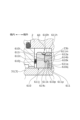
図1に示されるように、本実施例1のセグメントシール1A,1Bは、ハウジング2と該ハウジング2に挿通される回転軸3との間の環状空間をシールするために装着される。本実施例の回転軸3は、ステンレス鋼等の金属製の軸本体32と、軸本体32に外嵌されたステンレス鋼等の金属製のスリーブ31と、から構成されている。
As shown in FIG. 1, the segment seals 1A and 1B of the first embodiment are installed to seal the annular space between the housing 2 and the rotating shaft 3 inserted through the housing 2. The rotating shaft 3 of this embodiment includes a shaft body 32 made of metal such as stainless steel, and a sleeve 31 made of metal such as stainless steel that is fitted onto the shaft body 32.
また、本実施例1では、ハウジング2と回転軸3との間の環状空間に一対のセグメントシール1A,1Bが軸方向に並べて配置される、いわゆるタンデム型として構成されている。尚、一対のセグメントシール1A,1Bについて、機内側に配置されるものをセグメントシール1A、機外側に配置されるものをセグメントシール1Bとして説明する。
Furthermore, in the first embodiment, a pair of segment seals 1A and 1B are arranged side by side in the axial direction in an annular space between the housing 2 and the rotating shaft 3, so that the segment seals are configured as a so-called tandem type. The pair of segment seals 1A and 1B will be described with the segment seal 1A disposed on the inside of the machine and the segment seal 1B disposed on the outside of the machine.
先ず、ハウジング2の構造について詳しく説明する。図1に示されるように、ハウジング2は、セグメントシール1A,1Bを収納するための第1環状凹部23および第2環状凹部24が軸方向に並んで設けられている。尚、本実施例1では、ハウジング2は複数の部材から構成される分割構造となっているが、1つの部材から構成されていてもよい。
First, the structure of the housing 2 will be explained in detail. As shown in FIG. 1, the housing 2 is provided with a first annular recess 23 and a second annular recess 24 aligned in the axial direction for accommodating the segment seals 1A and 1B. In the first embodiment, the housing 2 has a divided structure composed of a plurality of members, but it may be composed of a single member.
図1および図2に示されるように、第1環状凹部23を構成する機内側の端面23aとセグメントシール1Aとの間には、付勢手段としてのスプリング4が配設されている。このスプリング4によりセグメントシール1Aは、第1環状凹部23を構成する機外側の設置面としての端面23bに向けて付勢されている。
As shown in FIGS. 1 and 2, a spring 4 as a biasing means is disposed between the inboard end surface 23a of the first annular recess 23 and the segment seal 1A. This spring 4 urges the segment seal 1A toward an end surface 23b that constitutes the first annular recess 23 and serves as an installation surface on the outside of the machine.
また、第2環状凹部24を構成する機内側の端面24aとセグメントシール1Bとの間には、付勢手段としてのスプリング4’が配設されている。このスプリング4’によりセグメントシール1Bは、第2環状凹部24を構成する機外側の設置面としての端面24bに向けて付勢されている。
Furthermore, a spring 4' serving as a biasing means is disposed between the inboard end surface 24a of the second annular recess 24 and the segment seal 1B. This spring 4' urges the segment seal 1B toward an end surface 24b constituting the second annular recess 24 and serving as an installation surface on the outside of the machine.
セグメントシール1A,1Bは、その内周面が後述のように回転軸3の外径側に僅かに離間して配置される非接触型のセグメントシールである(図5,図6参照)。このように、セグメントシール1A,1Bは、回転軸3のスリーブ31に非接触であって、両者の間に環状隙間g(以降単に隙間gということもある。(図5,図6参照))が形成されている。また、セグメントシール1A,1Bは、スプリング4,4’により端面23b,24bに圧接されているため、回転軸3と相対回転するようになっている。
The segment seals 1A and 1B are non-contact type segment seals whose inner circumferential surfaces are arranged slightly apart from each other on the outer diameter side of the rotating shaft 3 (see FIGS. 5 and 6). In this way, the segment seals 1A and 1B do not contact the sleeve 31 of the rotating shaft 3, and there is an annular gap g (hereinafter also simply referred to as gap g) between them (see FIGS. 5 and 6). is formed. Furthermore, the segment seals 1A and 1B are pressed against the end surfaces 23b and 24b by springs 4 and 4', so that they rotate relative to the rotating shaft 3.
次いで、セグメントシール1A,1Bの構造について詳しく説明する。尚、セグメントシール1A,1Bの構造はほぼ同一であるため、セグメントシール1Aのみ説明し、セグメントシール1Bの説明を省略する。
Next, the structure of the segment seals 1A and 1B will be explained in detail. Incidentally, since the structures of the segment seals 1A and 1B are almost the same, only the segment seal 1A will be explained, and the explanation of the segment seal 1B will be omitted.
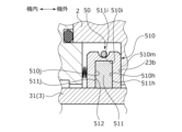
図2に示されるように、セグメントシール1Aは、基材リング10と樹脂製リング11とを備えている。
As shown in FIG. 2, the segment seal 1A includes a base ring 10 and a resin ring 11.
基材リング10は、回転軸3に外嵌されている。詳しくは、図3に示されるように、基材リング10は、周方向に3分割された分割体12を環状に組み合わせることで構成されている。尚、図3は常温における形状を示すものである。
The base ring 10 is fitted onto the rotating shaft 3. Specifically, as shown in FIG. 3, the base ring 10 is constructed by combining divided bodies 12 divided into three in the circumferential direction into an annular shape. Note that FIG. 3 shows the shape at room temperature.
分割体12は、カーボン製である。すなわち、分割体12は、金属製の回転軸3よりも熱膨張係数が低くなっている。
The divided body 12 is made of carbon. That is, the divided body 12 has a lower coefficient of thermal expansion than the rotating shaft 3 made of metal.
分割体12は、周方向一端の機内側から周方向一方側に突出する突出部12aと、周方向他端の機外側から周方向他方側に突出する突出部12bと、を有している。これら突出部12a,12bを軸方向に重畳させることで周方向に隣接する分割体12同士を軸方向に位置合わせすることができる。
The divided body 12 has a protrusion 12a that protrudes from the inside of the machine at one end in the circumferential direction to one side in the circumferential direction, and a protrusion 12b that protrudes from the outside of the machine at the other end in the circumferential direction to the other side in the circumferential direction. By overlapping these protrusions 12a and 12b in the axial direction, the circumferentially adjacent divided bodies 12 can be aligned in the axial direction.
突出部12aは突出部12bよりも周方向に長くなっている。また、分割体12の本体部における機内側の周方向端面12mと、突出部12aの周方向端面12nとは当接している。これにより、機内側の被密封流体が機外側に向けて軸方向に進入しにくくなっている。尚、分割体12の本体部における機外側の周方向端面12pと、突出部12bの周方向端面12qは周方向に僅かに離間している。
The protrusion 12a is longer in the circumferential direction than the protrusion 12b. Furthermore, the circumferential end surface 12m on the inboard side of the main body portion of the divided body 12 and the circumferential end surface 12n of the protruding portion 12a are in contact with each other. This makes it difficult for the fluid to be sealed inside the machine to enter toward the outside of the machine in the axial direction. Note that the circumferential end surface 12p of the main body portion of the divided body 12 on the outer side of the machine and the circumferential end surface 12q of the protruding portion 12b are slightly spaced apart in the circumferential direction.
また分割体12の外周面には、外径側に開口する断面視U字状の凹溝12cが周方向に亘って形成されている。この凹溝12cは、各分割体12を周方向に配置した状態で環状に形成される。各凹溝12cには、環状のガータスプリング13(図2参照)が装着され、これにより各分割体12が環状に保持される。
Further, on the outer circumferential surface of the divided body 12, a groove 12c having a U-shape in cross section and opening toward the outer diameter side is formed in the circumferential direction. This groove 12c is formed in an annular shape with each divided body 12 arranged in the circumferential direction. An annular garter spring 13 (see FIG. 2) is attached to each groove 12c, thereby holding each divided body 12 in an annular shape.
また、分割体12の機外側の端面12dの外径側は、段状に切り欠かれた窪部としての段部12hとなっている。詳しくは、端面12dの外径部12eは、端面12dの内径部12fと平行であり且つ内径部12fよりも機内側に配置されている。外径部12eと内径部12fとを繋ぐ連結部12gは、外径部12eおよび内径部12fと直交、すなわち軸方向に延びている。段部12hは外径部12eと連結部12gで区画されている。
Furthermore, the outer diameter side of the outer end surface 12d of the divided body 12 is a stepped portion 12h, which is a recessed portion cut out in a stepped manner. Specifically, the outer diameter portion 12e of the end surface 12d is parallel to the inner diameter portion 12f of the end surface 12d, and is arranged closer to the inside of the machine than the inner diameter portion 12f. A connecting portion 12g connecting the outer diameter portion 12e and the inner diameter portion 12f is perpendicular to the outer diameter portion 12e and the inner diameter portion 12f, that is, extends in the axial direction. The stepped portion 12h is divided by an outer diameter portion 12e and a connecting portion 12g.
図2に戻って、樹脂製リング11は、基材リング10に取付けられている。詳しくは、図4に示されるように、樹脂製リング11は、周方向に3分割された樹脂製分割体14を環状に組み合わせることで構成されている。尚、図4(a)は常温における形状を示すものである。
Returning to FIG. 2, the resin ring 11 is attached to the base ring 10. Specifically, as shown in FIG. 4, the resin ring 11 is constructed by combining resin segments 14 divided into three in the circumferential direction into an annular shape. Note that FIG. 4(a) shows the shape at room temperature.
樹脂製分割体14は、PTFE(ポリテトラフルオロエチレン)製である。すなわち、樹脂製分割体14は、金属製の回転軸3よりも熱膨張係数が高くなっている。尚、樹脂製分割体14は熱膨張率が金属製の回転軸3よりも大きければよく、樹脂材はPTFE以外にも、例えば、PEEK(ポリエーテルエーテルケトン)、PI(ポリイミド)等が使用可能である。
The resin divided body 14 is made of PTFE (polytetrafluoroethylene). That is, the resin divided body 14 has a higher coefficient of thermal expansion than the metal rotating shaft 3. Note that the resin divided body 14 only needs to have a coefficient of thermal expansion larger than that of the metal rotating shaft 3, and as the resin material, other than PTFE, for example, PEEK (polyetheretherketone), PI (polyimide), etc. can be used. It is.
樹脂製分割体14は、内径側部位としての径方向部位14aと、外径側部位および係合部としての軸方向部位14bと、を有し、断面視略逆L字状を成している。軸方向部位14bは、径方向部位14aの外径端から機内側に延びている。なお、径方向部位14aの内周側には、樹脂製分割体14の内周端部を含む軸方向面としての内周端部軸方向面14fを有している。
The resin divided body 14 has a radial region 14a as an inner diameter region, and an axial region 14b as an outer diameter region and an engaging portion, and has a substantially inverted L-shape when viewed in cross section. . The axial portion 14b extends inward from the outer diameter end of the radial portion 14a. Note that the radial portion 14a has an inner circumferential end axial surface 14f as an axial surface including the inner circumferential end of the resin divided body 14 on the inner circumferential side.
尚、本実施例では、常温時に周方向端面14e同士が当接している例について説明したが、周方向端面14e間が離間し、隙間が形成されていてもよい。後者の場合、熱膨張係数は樹脂製リング11の方がカーボン製の基材リング10よりも大きいため、周方向端面14e同士の隙間は基材リング10の分割体12の周方向端面12p、12q間の隙間よりも広い方が好ましい。
In this embodiment, an example in which the circumferential end surfaces 14e are in contact with each other at room temperature has been described, but the circumferential end surfaces 14e may be spaced apart to form a gap. In the latter case, since the resin ring 11 has a larger thermal expansion coefficient than the carbon base ring 10, the gap between the circumferential end faces 14e is equal to the circumferential end faces 12p, 12q of the divided body 12 of the base ring 10. It is preferable that the gap be wider than the gap between them.
図2に戻って、軸方向部位14bは、基材リング10における端面12dの外径部12eと連結部12gとで成す段部12h(図3参照)に嵌合して接着されている。詳しくは、軸方向部位14bの機内側の端面14cが基材リング10における端面12dの外径部12eに接着材により接着されており、軸方向部位14bの内周面14dが基材リング10における端面12dの連結部12gに接着材により接着されている。尚、樹脂製リング11の径方向部位14aは、基材リング10における端面12dの内径部12fに接着されていない。
Returning to FIG. 2, the axial portion 14b is fitted and bonded to a stepped portion 12h (see FIG. 3) formed by the outer diameter portion 12e of the end surface 12d of the base ring 10 and the connecting portion 12g. Specifically, the end surface 14c of the axial portion 14b on the inboard side is bonded to the outer diameter portion 12e of the end surface 12d of the base ring 10 with an adhesive, and the inner circumferential surface 14d of the axial portion 14b is bonded to the outer diameter portion 12e of the end surface 12d of the base ring 10. It is bonded to the connecting portion 12g of the end surface 12d with an adhesive. Note that the radial portion 14a of the resin ring 11 is not bonded to the inner diameter portion 12f of the end surface 12d of the base ring 10.
この樹脂製分割体14は、一の分割体12の本体部における機外側の軸方向端面12rと、隣接する他の分割体12の突出部12bにおける機外側の軸方向端面12sと、に亘って配置される(図示略)。軸方向部位14bは、一の分割体12の段部12hに接着され、他の分割体12の段部12hには接着されていない。
This resin divided body 14 extends between an axial end face 12r on the outboard side of the main body of one divided body 12 and an axial end face 12s on the outboard side of the protrusion 12b of the other adjacent divided body 12. (not shown). The axial portion 14b is bonded to the stepped portion 12h of one divided body 12, and is not bonded to the stepped portion 12h of the other divided body 12.
基材リング10の各分割体12に樹脂製分割体14を取付けた状態において、樹脂製分割体14の周方向端面14e同士は当接している。また、樹脂製分割体14は、分割体12の本体部における機外側の周方向端面12pと突出部12bの周方向端面12qとの隙間を軸方向に被覆している。これにより、機内側の被密封流体が機外側に向けて軸方向に進入しにくくなっている。また、樹脂製分割体14の機外側端面14gがハウジング2の端面23bと当接しており、機内側の被密封流体が機外側に向けて径方向に進入しにくくなっている。
In the state where the resin divided body 14 is attached to each divided body 12 of the base ring 10, the circumferential end surfaces 14e of the resin divided body 14 are in contact with each other. Furthermore, the resin divided body 14 covers in the axial direction the gap between the outer circumferential end surface 12p of the main body portion of the divided body 12 and the circumferential end surface 12q of the protruding portion 12b. This makes it difficult for the fluid to be sealed inside the machine to enter toward the outside of the machine in the axial direction. Furthermore, the outer side end surface 14g of the resin divided body 14 is in contact with the end surface 23b of the housing 2, making it difficult for the sealed fluid inside the machine to enter in the radial direction toward the outer side of the machine.
尚、軸方向部位14bは、段部12hに嵌合して接着される形態を例示したが、接着されていなくてもよい。また、例えば、後述の実施例2~4のように、嵌合、圧入、熱膨張差での固定等でも良い。
Note that, although the axial portion 14b is fitted into and bonded to the stepped portion 12h, it does not have to be bonded. Further, for example, as in Examples 2 to 4 described later, fitting, press-fitting, fixing by thermal expansion difference, etc. may be used.
また、図5に示されるように、常温の温度域では、樹脂製リング11の内周面が基材リング10の内周面よりも外径側に配置されている。
Further, as shown in FIG. 5, in the normal temperature range, the inner circumferential surface of the resin ring 11 is arranged on the outer diameter side than the inner circumferential surface of the base ring 10.
次に、温度環境の変化に応じたセグメントシール1Aのシール機能について図5及び図6を用いて説明する。図5及び図6では、説明の便宜上、セグメントシール1Aと回転軸3との隙間gを実際よりも大きく図示している。
Next, the sealing function of the segment seal 1A in response to changes in the temperature environment will be explained using FIGS. 5 and 6. In FIGS. 5 and 6, for convenience of explanation, the gap g between the segment seal 1A and the rotating shaft 3 is illustrated to be larger than it actually is.
また、ここでは、機外側の流体が一の温度域である場合のシール機能と、機外側の流体が他の温度域である場合のシール機能と、について説明する。尚、本実施例では、一の温度域を常温の温度域、他の温度域を極低温の温度域として説明する。ここで、極低温は0℃以下、好ましくは-100℃以下である。
Also, here, a sealing function when the fluid outside the machine is in one temperature range and a sealing function when the fluid outside the machine is in another temperature range will be explained. In this embodiment, one temperature range will be described as a normal temperature range, and the other temperature range will be explained as an extremely low temperature range. Here, the extremely low temperature is 0°C or lower, preferably -100°C or lower.
図5に示されるように、機外側の流体が一の温度域では、セグメントシール1Aと回転軸3との隙間gが形成されている。隙間gは、基材リング10の内周面がスリーブ31の外径側に僅かな幅L1で離間して配置されている。一方、樹脂製リング11の内周面は、スリーブ31の外径側に幅L1よりも大きな幅L2で離間して配置されている(L1<L2)。
As shown in FIG. 5, a gap g is formed between the segment seal 1A and the rotating shaft 3 when the fluid outside the machine is in one temperature range. The gap g is arranged such that the inner peripheral surface of the base ring 10 is spaced apart from the outer diameter side of the sleeve 31 by a slight width L1. On the other hand, the inner peripheral surface of the resin ring 11 is spaced apart from the outer diameter side of the sleeve 31 by a width L2 that is larger than the width L1 (L1<L2).
基材リング10とスリーブ31との僅かな隙間によりセグメントシール1Aと回転軸3との隙間gがシールされている。尚、樹脂製リング11は実質的なシールとして機能していない。
A gap g between the segment seal 1A and the rotating shaft 3 is sealed by a small gap between the base ring 10 and the sleeve 31. Note that the resin ring 11 does not function as a substantial seal.
尚、ここでいうシールとは、機内側と機外側とが完全に密封されることに限られず、機内側と機外側との間で流体の移動が規制されること、言い換えれば、機内側と機外側との間で一部流体の移動が許容されていることも含まれる。
Note that the term "seal" here does not mean that the inside of the machine and the outside of the machine are completely sealed; it means that the movement of fluid is regulated between the inside of the machine and the outside of the machine. This also includes allowing some fluid movement to and from the outside of the aircraft.
図6に示されるように、機外側の流体が極低温である他の温度域では、セグメントシール1Aと回転軸3との隙間g’が形成される。詳しくは、回転軸3と基材リング10との熱膨張係数の差により、回転軸3が基材リング10よりも大きく熱収縮する。これにより、基材リング10とスリーブ31との間の幅L1’が拡大し、基材リング10はシールとしての実質的な機能が低下または機能しなくなる(L1<L1’)。
As shown in FIG. 6, in other temperature ranges where the fluid outside the machine is at an extremely low temperature, a gap g' is formed between the segment seal 1A and the rotating shaft 3. Specifically, due to the difference in coefficient of thermal expansion between the rotating shaft 3 and the base ring 10, the rotating shaft 3 thermally shrinks more than the base ring 10. As a result, the width L1' between the base ring 10 and the sleeve 31 increases, and the base ring 10's substantial function as a seal is reduced or ceases to function (L1<L1').
機外側の流体が極低温である他の温度域では、図7を参照し、基材リング10は中心に向かって僅かに全体的に縮まり、周方向端面12p、12q間の隙間が狭くなる。また、図8を参照し、樹脂製リング11は、周方向端面14e同士は当接した状態で、全体が中心に向かって縮まる。なお、全体的な縮まり代は、樹脂製リング11の方が大きい。また、図7,8において、常温である一の温度域の形状を2点破線で示している。
In other temperature ranges where the fluid outside the machine is at an extremely low temperature, referring to FIG. 7, the base ring 10 shrinks slightly as a whole toward the center, and the gap between the circumferential end surfaces 12p and 12q narrows. Further, referring to FIG. 8, the entire resin ring 11 contracts toward the center while the circumferential end surfaces 14e are in contact with each other. Note that the resin ring 11 has a larger overall shrinkage margin. Moreover, in FIGS. 7 and 8, the shape of one temperature range, which is room temperature, is shown by a two-dot broken line.
一方、回転軸3と樹脂製リング11との熱膨張係数の差により、樹脂製リング11が回転軸3よりも大きく熱収縮する。これにより、樹脂製リング11の内周面がスリーブ31の外径側に僅かな幅L2’で離間するように配置される(L2>L2’)。幅L2’は幅L1’よりも小さい(L1’>L2’)。
On the other hand, due to the difference in thermal expansion coefficient between the rotating shaft 3 and the resin ring 11, the resin ring 11 thermally shrinks more than the rotating shaft 3. Thereby, the inner peripheral surface of the resin ring 11 is arranged so as to be spaced apart from the outer diameter side of the sleeve 31 by a slight width L2' (L2>L2'). Width L2' is smaller than width L1' (L1'>L2').
このように、機外側の流体が他の温度域では、樹脂製リング11とスリーブ31との僅かな隙間によりセグメントシール1Aと回転軸3との隙間g’がシールされる。
In this way, when the fluid outside the machine is in a different temperature range, the gap g' between the segment seal 1A and the rotating shaft 3 is sealed by the small gap between the resin ring 11 and the sleeve 31.
以上説明したように、機外側の流体が他の温度域よりも高温環境である一の温度域では、基材リング10がシール機能を発揮するとともに、一の温度域よりも低温環境である他の温度域では、基材リング10と並列に配置された樹脂製リング11がシール機能を発揮するため、幅広い温度域でシール機能を発揮することができる。
As explained above, the base ring 10 exhibits a sealing function in one temperature range in which the fluid outside the machine is higher in temperature than in other temperature ranges, and in an environment in which the fluid outside the machine is in a lower temperature range than in the other temperature range. Since the resin ring 11 arranged in parallel with the base ring 10 exhibits a sealing function in the temperature range of , it is possible to exhibit a sealing function in a wide temperature range.
また、樹脂製リング11は剛性の高い基材リング10に固定されているため、樹脂製リング11の形状を安定させることができる。
Furthermore, since the resin ring 11 is fixed to the highly rigid base ring 10, the shape of the resin ring 11 can be stabilized.
また、樹脂製リング11は、基材リング10よりも靭性が高いため、収縮しても、基材リング10に対する係合部となる軸方向部位14bが破損するおそれは低い。
Furthermore, since the resin ring 11 has higher toughness than the base ring 10, even if it contracts, there is a low possibility that the axial portion 14b, which becomes the engagement portion with the base ring 10, will be damaged.
また、樹脂製リング11の軸方向部位14bが基材リング10の段部12hに係合して取付けられるため、樹脂製リング11は内径方向に基材リング10よりも大きく熱変形可能となっており、熱膨張差を利用したシール性の確保ができる。また、基材リング10の調芯機能に樹脂製リング11も追随できるため、低温域でも樹脂製リング11によりシール機能を発揮できる。
Furthermore, since the axial portion 14b of the resin ring 11 is attached by engaging with the stepped portion 12h of the base ring 10, the resin ring 11 can be thermally deformed in the inner diameter direction to a greater degree than the base ring 10. This makes it possible to ensure sealing performance by utilizing the difference in thermal expansion. Furthermore, since the resin ring 11 can follow the alignment function of the base ring 10, the resin ring 11 can exhibit a sealing function even in a low temperature range.
また、収縮により、基材リング10の内径部12fと樹脂製リング11の機外側端面14hとの間に軸方向隙間ができる可能性もあるが次の理由からこの部分からの漏れは抑制できている。樹脂製リング11は基材リング10に固定されていること、及び樹脂製分割体14同士が周方向で当接していることからである。
Furthermore, due to shrinkage, there is a possibility that an axial gap may be formed between the inner diameter portion 12f of the base ring 10 and the outer end surface 14h of the resin ring 11, but leakage from this portion can be suppressed for the following reasons. There is. This is because the resin ring 11 is fixed to the base ring 10 and the resin divided bodies 14 are in contact with each other in the circumferential direction.
また、樹脂製リング11の内径側に基材リング10が配置されないため、使用される温度環境の変化に応じて樹脂製リング11を内径方向に熱変形させ、樹脂製リング11とスリーブ31との間の隙間を確実に調整できる。
In addition, since the base ring 10 is not arranged on the inner diameter side of the resin ring 11, the resin ring 11 is thermally deformed in the inner diameter direction according to changes in the temperature environment in which it is used, and the resin ring 11 and the sleeve 31 are The gap between the two can be adjusted reliably.
また、樹脂製リング11の径方向部位14aが基材リング10に位置規制され、軸方向部位14bが基材リング10に対して径方向にスライド可能となっている。具体的には、軸方向部位14bは、基材リング10における端面12dの外径部12eと連結部12gとで成す段部に嵌合して接着されており、径方向部位14aは、基材リング10における端面12dの内径部12fに接着されておらず、径方向部位14aの内周端部軸方向面14fとこの面に対向する分割体12の軸方向面としての内径部12fの対向面12iはそれぞれ径方向に延びる平面をなしている。そのため、温度環境の変化に応じて軸方向部位14bを熱変形させ、内径方向に確実にスライドさせることができる。
Furthermore, the position of the radial portion 14a of the resin ring 11 is regulated by the base ring 10, and the axial portion 14b is slidable relative to the base ring 10 in the radial direction. Specifically, the axial portion 14b is fitted and bonded to a step formed by the outer diameter portion 12e of the end surface 12d of the base ring 10 and the connecting portion 12g, and the radial portion 14a is bonded to the base material ring 10. An opposing surface of the inner diameter portion 12f, which is not bonded to the inner diameter portion 12f of the end surface 12d of the ring 10, and is an axial surface of the inner circumferential end of the radial portion 14a and the axial surface of the divided body 12 that opposes this surface. 12i each constitute a plane extending in the radial direction. Therefore, the axial portion 14b can be thermally deformed in response to changes in the temperature environment, and can be reliably slid in the inner diameter direction.
また、樹脂製リング11は、周方向に複数分割された樹脂製分割体14から構成されており、各前記樹脂製分割体14は、基材リング10を構成する各分割体12に固定されている。これによれば、軸ブレ等により回転軸3が径方向に移動したときに、各樹脂製分割体14は基材リング10の各分割体12とともに回転軸3の径方向の移動に追従することができる。
Further, the resin ring 11 is composed of a plurality of resin divided bodies 14 divided in the circumferential direction, and each of the resin divided bodies 14 is fixed to each divided body 12 constituting the base ring 10. There is. According to this, when the rotary shaft 3 moves in the radial direction due to shaft wobbling or the like, each resin divided body 14 follows the radial movement of the rotary shaft 3 together with each divided body 12 of the base ring 10. I can do it.
また、樹脂製リング11が固定される基材リング10は、剛性を有する各分割体12の外周面に亘って配置される環状のガータスプリング13により環状に保持されているため、樹脂製リング11にガータスプリング13の弾性力が作用せず、樹脂製リング11の変形を防止できる。
Furthermore, the base ring 10 to which the resin ring 11 is fixed is annularly held by an annular garter spring 13 disposed over the outer circumferential surface of each rigid divided body 12. Since the elastic force of the garter spring 13 does not act on the resin ring 11, deformation of the resin ring 11 can be prevented.
また、セグメントシール1A,1Bは、基材リング10を軸方向に付勢するスプリング4,4’によりハウジング2の端面23b,24bに対して圧接されている。これによれば、スプリング4,4’によりセグメントシール1A,1Bをハウジング2の端面23b,24bに圧接させて保持できるとともに、スプリング4,4’の付勢力が基材リング10に作用するため、樹脂製リング11にスプリング4,4’の付勢力が直接作用せず、樹脂製リング11の変形を防止できる。
Furthermore, the segment seals 1A and 1B are pressed against the end surfaces 23b and 24b of the housing 2 by springs 4 and 4' that urge the base ring 10 in the axial direction. According to this, the segment seals 1A, 1B can be held in pressure contact with the end surfaces 23b, 24b of the housing 2 by the springs 4, 4', and the biasing force of the springs 4, 4' acts on the base ring 10, so that The urging force of the springs 4, 4' does not directly act on the resin ring 11, and deformation of the resin ring 11 can be prevented.
また、ハウジング2の端面23b,24bには、セグメントシール1A,1Bの各樹脂製リング11が当接し、摺動性が高くなっているため、軸ブレ等により回転軸3が径方向に移動したときに、その移動に対してセグメントシール1A,1Bが円滑に追従できるようになっている。
In addition, the resin rings 11 of the segment seals 1A and 1B are in contact with the end surfaces 23b and 24b of the housing 2, and the sliding properties are high, so that the rotating shaft 3 is prevented from moving in the radial direction due to shaft wobbling, etc. At times, the segment seals 1A and 1B can smoothly follow the movement.
また、低圧側である機外側に樹脂製リング11が配置されているため、樹脂製リング11は高圧側である機内側の被密封流体の流体圧の影響を受けにくい。具体的には、樹脂はカーボンよりも温度や圧力に対する変形が大きくなるため、セグメントシール1A,1Bを樹脂で構成すると、流体圧・スプリング圧・ガータスプリング圧・温度変化等で変形し、機能低下・機能喪失の可能性があるが、本構造はセグメントシール1A,1Bの基部をカーボン製の基材リング10とし、その低圧側に樹脂製リング11を装着しているため、圧力や温度による変形の影響を受けにくくなり、高圧や低温環境でも径方向への高い追随性を維持できる。
Furthermore, since the resin ring 11 is arranged on the outside of the machine, which is the low pressure side, the resin ring 11 is not easily affected by the fluid pressure of the fluid to be sealed inside the machine, which is the high pressure side. Specifically, resin deforms more easily than carbon due to temperature and pressure, so if segment seals 1A and 1B are made of resin, they will deform due to fluid pressure, spring pressure, garter spring pressure, temperature changes, etc., resulting in decreased functionality. - Although there is a possibility of loss of function, this structure uses a carbon base ring 10 at the base of the segment seals 1A and 1B, and a resin ring 11 is attached to the low pressure side, so there is no possibility of deformation due to pressure or temperature. This makes it less susceptible to the effects of heat and maintains high tracking ability in the radial direction even in high-pressure and low-temperature environments.
また、セグメントシール1A,1Bがハウジング2に対して相対回転しても、樹脂製リング1は自己潤滑性優れるため損傷が少ない。
Furthermore, even if the segment seals 1A, 1B rotate relative to the housing 2, the resin ring 1 has excellent self-lubricating properties, so there is little damage.
次に、実施例2に係るセグメントシールにつき、図9を参照して説明する。尚、前記実施例1と同一構成で重複する構成の説明を省略する。
Next, a segment seal according to Example 2 will be described with reference to FIG. 9. Note that explanations of the same and overlapping configurations as those of the first embodiment will be omitted.
図9に示されるように、本実施例2のセグメントシール40は、基材リング410と、樹脂製リング411とを備えている。
As shown in FIG. 9, the segment seal 40 of the second embodiment includes a base ring 410 and a resin ring 411.
基材リング410は、樹脂製リング411を嵌合可能な環状の嵌合凹部412を機外側に有している。嵌合凹部412は、外径側部位412aが内径側部位412bよりも機内側に深くなっている。言い換えれば、嵌合凹部412は、断面視略逆L字状を成している。尚、嵌合凹部412の外径側部位412aには、基材リング410の環状部410aが形成されている。
The base ring 410 has an annular fitting recess 412 on the outside of the machine into which a resin ring 411 can be fitted. In the fitting recess 412, an outer diameter side portion 412a is deeper toward the inside of the machine than an inner diameter side portion 412b. In other words, the fitting recess 412 has a substantially inverted L shape when viewed in cross section. Note that an annular portion 410a of the base ring 410 is formed at an outer diameter side portion 412a of the fitting recess 412.
嵌合凹部412は、軸方向に延びる面410h、面410hから内径側に延びる面410i、面410iから軸方向機外側に延びる面410j、面410jから内径側に延びる面410kにより画成されている。
The fitting recess 412 is defined by a surface 410h extending in the axial direction, a surface 410i extending inward from the surface 410h, a surface 410j extending axially outward from the surface 410i, and a surface 410k extending inward from the surface 410j. .
樹脂製リング411は、内径側部位としての径方向部位414aと、外径側部位としての軸方向部位414bと、を有し、断面視略逆L字状を成している。
The resin ring 411 has a radial region 414a as an inner diameter region and an axial region 414b as an outer diameter region, and has a substantially inverted L-shape when viewed in cross section.
樹脂製リング411の外周面411hは面410hに対向配置されている。同様に、機内側かつ外径側の端面411iは面410iに、中間周面411jは面410jに、機内側かつ内径側の端面411kは面410kに、それぞれ対向配置されている。
The outer circumferential surface 411h of the resin ring 411 is arranged to face the surface 410h. Similarly, the end surface 411i on the inboard side and the outer diameter side is disposed to face the surface 410i, the intermediate peripheral surface 411j is opposed to the surface 410j, and the end surface 411k on the inboard side and the inner diameter side is opposed to the surface 410k.
樹脂製リング411は、基材リング410との熱膨張係数の差を利用して嵌合凹部412に取付けられていてもよいし、嵌合凹部412に圧入されていてもよい。尚、接着や嵌合等でもよく固定方法は限定されない。
The resin ring 411 may be attached to the fitting recess 412 by utilizing the difference in thermal expansion coefficient from the base ring 410, or may be press-fitted into the fitting recess 412. Note that the fixing method is not limited, and may be adhesive, fitting, or the like.
このように、樹脂製リング411の軸方向部位414bは、嵌合凹部412の外径側部位412aに嵌合されるため、樹脂製リング411は、実施例1に比べて基材リング410に強固に取付けられる。そのため、樹脂製リング411は、機内側の流体の影響を受けにくい。
In this way, since the axial portion 414b of the resin ring 411 is fitted into the outer diameter side portion 412a of the fitting recess 412, the resin ring 411 is more firmly attached to the base ring 410 than in the first embodiment. mounted on. Therefore, the resin ring 411 is not easily affected by the fluid inside the machine.
また、軸方向部位414bが嵌合凹部412の外径側部位412aに嵌合されることで、径方向部位414aが内径方向に確実に熱変形できる。
Further, by fitting the axial portion 414b into the outer diameter side portion 412a of the fitting recess 412, the radial portion 414a can be reliably thermally deformed in the inner diameter direction.
樹脂製リング411が嵌合凹部412に嵌合された状態にあっては、環状部410aの機外側端面と径方向部位414aの機外側端面とが面一となっている。
When the resin ring 411 is fitted into the fitting recess 412, the outer end surface of the annular portion 410a and the outer end surface of the radial portion 414a are flush with each other.
また、収縮により、樹脂製リング411の径方向部位414a、軸方向部位414bと基材リング410の嵌合凹部412の内径側部位412b、外径側部位412aとの間に隙間ができる可能性もあるが次の理由からこの部分からの漏れは抑制できている。樹脂製リング411は基材リング410に少なくとも一部で固定されていること、及び樹脂製リング411の機外側端面411mはハウジング2の端面23bに軸方向で当接していることからである。
In addition, due to contraction, there is a possibility that a gap may be formed between the radial portion 414a and axial portion 414b of the resin ring 411 and the inner diameter portion 412b and outer diameter portion 412a of the fitting recess 412 of the base ring 410. However, leakage from this part can be suppressed for the following reasons. This is because the resin ring 411 is at least partially fixed to the base ring 410, and the outer end surface 411m of the resin ring 411 contacts the end surface 23b of the housing 2 in the axial direction.
また、樹脂製リング411は、基材リング410よりも靭性が高いため、収縮しても、基材リング410に対する係合部となる軸方向部位414bが破損するおそれは低い。
Furthermore, since the resin ring 411 has higher toughness than the base ring 410, even if it contracts, there is a low possibility that the axial portion 414b, which becomes the engagement portion with the base ring 410, will be damaged.
次に、実施例3に係るセグメントシールにつき、図10を参照して説明する。尚、前記実施例1と同一構成で重複する構成の説明を省略する。
Next, a segment seal according to Example 3 will be described with reference to FIG. 10. Note that explanations of the same and overlapping configurations as those of the first embodiment will be omitted.
図10に示されるように、本実施例2のセグメントシール50は、基材リング510と、樹脂製リング511とを備えている。
As shown in FIG. 10, the segment seal 50 of the second embodiment includes a base ring 510 and a resin ring 511.
基材リング510は、内径方向に開口する環状凹部512が環状に形成されている。樹脂製リング511は、断面矩形状を成している。基材リング510と樹脂製リング511には図示しない軸方向に延びるピンが挿通されており、樹脂製リング511は、環状凹部512に取付固定されている。尚、圧入、接着、嵌合等でもよく固定方法は限定されない。
The base ring 510 has an annular recess 512 that opens in the inner diameter direction. The resin ring 511 has a rectangular cross section. A pin (not shown) extending in the axial direction is inserted into the base ring 510 and the resin ring 511, and the resin ring 511 is fixedly attached to the annular recess 512. Note that the fixing method is not limited, and may be press-fitting, adhesion, fitting, or the like.
環状凹部512は機外側で径方向に延びる面510h、面510hから軸方向に延びる面510i、面510iから内径方向延びる面510jにより画成されている。
The annular recess 512 is defined by a surface 510h extending in the radial direction on the outside of the machine, a surface 510i extending in the axial direction from the surface 510h, and a surface 510j extending in the inner radial direction from the surface 510i.
樹脂製リング511の機外側端面511hは面510hに対向配置されている。同様に、外周面511iは面510iに、機内側端面511jは面510jに、それぞれ対向配置されている。
The outer end surface 511h of the resin ring 511 is arranged to face the surface 510h. Similarly, the outer circumferential surface 511i and the inboard end surface 511j are arranged to face the surface 510i and the surface 510j, respectively.
これによれば、基材リング510の環状凹部512により、樹脂製リング511の外径側部位の軸方向両側および外径側が位置規制されるため、内径側部位を内径方向に確実にスライドさせることができる。
According to this, the annular recess 512 of the base ring 510 restricts the position of both axial sides and the outer diameter side of the outer diameter side portion of the resin ring 511, so that the inner diameter side portion can be reliably slid in the inner diameter direction. I can do it.
また、収縮の際に、樹脂製リング511と基材リング510の環状凹部512との間に隙間ができても、高圧流体が低圧側に流れる際に樹脂製リング511は軸方向に移動できるため基材リング510から脱落を防止できる。
Furthermore, even if a gap is created between the resin ring 511 and the annular recess 512 of the base ring 510 during contraction, the resin ring 511 can move in the axial direction when the high pressure fluid flows to the low pressure side. Falling off from the base ring 510 can be prevented.
また、基材リング510の機外側端面510mはハウジング2の端面23bに軸方向で当接し、当該箇所で密封するようになっている。
Furthermore, the outer end surface 510m of the base ring 510 abuts the end surface 23b of the housing 2 in the axial direction, and is sealed at that location.
次に、実施例4に係るセグメントシールにつき、図11を参照して説明する。尚、前記実施例2と同一構成で重複する構成の説明を省略する。
Next, a segment seal according to Example 4 will be described with reference to FIG. 11. Note that explanations of the same and overlapping configurations as those of the second embodiment will be omitted.
図11に示されるように、本実施例4のセグメントシール60は、基材リング610と、樹脂製リング611とを備えている。
As shown in FIG. 11, the segment seal 60 of the fourth embodiment includes a base ring 610 and a resin ring 611.
基材リング610の嵌合凹部612は、外径側部位612aにおける機内側の端部に内径側に凹む凹部612cが形成されている。
The fitting recess 612 of the base ring 610 has a recess 612c recessed toward the inner diameter at the end of the outer diameter side portion 612a on the machine side.
嵌合凹部612は、軸方向に延びる面610h、面610hから内径側に延びる面610i、面610iから軸方向機外側に延びる面610j、面610jから外径側に延びる面610k、面610kから軸方向に延びる面610p、面610pから内径方向に延びる面610qにより画成されている。また凹部612cは面610i、面610j、面610kにより画成されている。
The fitting recess 612 has a surface 610h extending in the axial direction, a surface 610i extending from the surface 610h toward the inner diameter side, a surface 610j extending from the surface 610i toward the outside in the axial direction, a surface 610k extending from the surface 610j toward the outer diameter side, and a surface 610k extending from the surface 610k toward the axial direction. It is defined by a surface 610p extending in the direction, and a surface 610q extending in the inner diameter direction from the surface 610p. Further, the recessed portion 612c is defined by a surface 610i, a surface 610j, and a surface 610k.
樹脂製リング611の軸方向部位614bの機内側の端部には、内径側に突出する凸部614cが形成されている。
A convex portion 614c that protrudes toward the inner diameter side is formed at the end of the axial portion 614b of the resin ring 611 on the inboard side.
樹脂製リング611の外周面611hは面610hに対向配置されている。同様に、機内側かつ外径側の端面611iは面610iに、内径側の中間周面611jは面610jに、径方向に延びる連結面611kは面610kに、外径側の中間周面611pは面610pに、機内側かつ内径側の端面611qは面610qに、それぞれ対向配置されている。また、凸部614cは端面611i、中間周面611j、連結面611kにより画成されている。
The outer circumferential surface 611h of the resin ring 611 is arranged to face the surface 610h. Similarly, the end surface 611i on the inside and outside diameter side is connected to the surface 610i, the intermediate peripheral surface 611j on the inside diameter side is connected to the surface 610j, the connecting surface 611k extending in the radial direction is connected to the surface 610k, and the intermediate peripheral surface 611p on the outside diameter side is connected to the surface 610j. An end surface 611q on the inboard side and inner diameter side is arranged to face the surface 610p and the surface 610q, respectively. Further, the convex portion 614c is defined by an end surface 611i, an intermediate circumferential surface 611j, and a connecting surface 611k.
樹脂製リング611の凸部614cは、基材リング610の凹部612cに嵌合するため、基材リング610と樹脂製リング611とは軸方向に離脱することが防止され、強固に固定される。
Since the convex portion 614c of the resin ring 611 fits into the recess 612c of the base ring 610, the base ring 610 and the resin ring 611 are prevented from coming apart in the axial direction and are firmly fixed.
凹部612cと凸部614c以外の箇所で、基材リング610と樹脂製リング611との間に隙間ができる可能性があるが、次の理由からこの部分からの漏れは抑制できている。樹脂製リング611は基材リング610に少なくとも一部で固定されていること、及び樹脂製リング611の機外側端面611mはハウジング2の端面23bに軸方向で当接していることからである。
Although there is a possibility that a gap may be formed between the base ring 610 and the resin ring 611 at a location other than the concave portion 612c and the convex portion 614c, leakage from this portion can be suppressed for the following reason. This is because the resin ring 611 is at least partially fixed to the base ring 610, and the outer end surface 611m of the resin ring 611 is in contact with the end surface 23b of the housing 2 in the axial direction.
また、樹脂製リング611は、基材リング610よりも靭性が高いため、収縮しても、破損するおそれは低い。
Furthermore, since the resin ring 611 has higher toughness than the base ring 610, there is a low possibility that it will be damaged even if it contracts.
以上、本発明の実施例を図面により説明してきたが、具体的な構成はこれら実施例に限られるものではなく、本発明の要旨を逸脱しない範囲における変更や追加があっても本発明に含まれる。
Although the embodiments of the present invention have been described above with reference to the drawings, the specific configuration is not limited to these embodiments, and any changes or additions that do not depart from the gist of the present invention are included in the present invention. It will be done.
例えば、前記実施例1~4では、基材リングが周方向に3分割されている形態を例示したが、2分割以上であれば分割数は自由に変更できる。
For example, in Examples 1 to 4, the base ring is divided into three parts in the circumferential direction, but the number of divisions can be changed freely as long as it is two or more parts.
また、前記実施例1~4では、樹脂製リングが周方向に3分割されている形態を例示したが、分割数は自由に変更できる。また、分割されず1つの部材から構成されていてもよい。
Further, in Examples 1 to 4, the resin ring is divided into three parts in the circumferential direction, but the number of divisions can be changed freely. Alternatively, it may be composed of one member without being divided.
また、前記実施例1~4では、樹脂製リングの外径側部位が基材リングに位置規制されている形態を例示したが、樹脂製リングの外径側部位が径方向に変形可能に基材リングに取付けられていてもよい。
In addition, in Examples 1 to 4, the outer diameter side portion of the resin ring is regulated in position by the base ring, but the outer diameter side portion of the resin ring is based on the base material so that it can be deformed in the radial direction. It may be attached to a material ring.
また、前記実施例1~4では、基材リングにガータスプリングが取付けられる形態を例示したが、樹脂製リングにガータスプリングが取付けられていてもよい。
Further, in Examples 1 to 4, the garter spring is attached to the base ring, but the garter spring may be attached to the resin ring.
また、前記実施例1~4では、基材リングが付勢手段により付勢される形態を例示したが、樹脂製リングが付勢手段により付勢されてもよい。
Further, in Examples 1 to 4, the base ring is biased by the biasing means, but a resin ring may be biased by the biasing means.
また、前記実施例1~4では、非接触型のセグメントシールを例示したが、接触型のセグメントシールであってもよい。
Furthermore, in Examples 1 to 4, non-contact type segment seals were exemplified, but contact type segment seals may also be used.
また、前記実施例1~4では、タンデム型のセグメントシールを例示したが、シングル型やダブル型のセグメントシールであってもよい。
Further, in Examples 1 to 4, tandem-type segment seals were exemplified, but single-type or double-type segment seals may also be used.
また、前記実施例1~4では、回転軸は軸本体とスリーブから構成される例を説明したが、スリーブを用いることなく軸本体のみから構成されていてもよい。
Furthermore, in Examples 1 to 4, the rotary shaft is composed of a shaft body and a sleeve, but it may be composed only of the shaft body without using a sleeve.
また、前記実施例1~4では、基材リング側の側面に窪部を設け、樹脂製リングに凸状の係合部を設ける形態を例示したが、基材リング側の側面に突起部を設け、樹脂製リングに突起部に係合する凹状の係合部を設けてもよい。
Furthermore, in Examples 1 to 4, a configuration in which a recess is provided on the side surface on the base ring side and a convex engaging portion is provided on the resin ring is illustrated, but a protrusion is provided on the side surface on the base ring side. The resin ring may be provided with a concave engaging portion that engages with the protrusion.
また、機内側の高圧流体はその種別は問わず、例えば被密封流体であってもシールガスであってもよい。
Furthermore, the type of high-pressure fluid inside the machine does not matter, and may be, for example, a sealed fluid or a sealing gas.
1A,1B セグメントシール
2 ハウジング
3 回転軸
4,4’ スプリング
10 基材リング
11 樹脂製リング
12 分割体
12h 段部(窪部)
13 ガータスプリング
14 樹脂製分割体
14a 径方向部位(内径側部位)
14b 軸方向部位(外径側部位、係合部)
23b,24b 端面(設置面)
40,50,60 セグメントシール
410 基材リング
411 樹脂製リング
510 基材リング
511 樹脂製リング
610 基材リング
611 樹脂製リング
g、g’ 隙間(環状隙間) 1A,1B Segment seal 2 Housing 3 Rotating shaft 4, 4' Spring 10 Base ring 11 Resin ring 12 Divided body 12h Step portion (depression)
13Garter spring 14 Resin divided body 14a Radial direction part (inner diameter side part)
14b Axial part (outer diameter side part, engagement part)
23b, 24b End surface (installation surface)
40, 50, 60Segment seal 410 Base ring 411 Resin ring 510 Base ring 511 Resin ring 610 Base ring 611 Resin rings g, g' Gap (annular gap)
2 ハウジング
3 回転軸
4,4’ スプリング
10 基材リング
11 樹脂製リング
12 分割体
12h 段部(窪部)
13 ガータスプリング
14 樹脂製分割体
14a 径方向部位(内径側部位)
14b 軸方向部位(外径側部位、係合部)
23b,24b 端面(設置面)
40,50,60 セグメントシール
410 基材リング
411 樹脂製リング
510 基材リング
511 樹脂製リング
610 基材リング
611 樹脂製リング
g、g’ 隙間(環状隙間) 1A,
13
14b Axial part (outer diameter side part, engagement part)
23b, 24b End surface (installation surface)
40, 50, 60
Claims (9)
- ハウジングと該ハウジングに挿通された回転軸との間に回転を規制された状態で配置され、前記ハウジングと前記回転軸との間をシールするセグメントシールであって、
前記セグメントシールは、
前記回転軸に外嵌され、周方向に複数分割された分割体から構成される基材リングと、
前記基材リングと軸方向に並んで配置される樹脂製リングと、を備え、前記樹脂製リングの軸方向高圧側には、前記基材リングの少なくとも一部が配置されており、前記樹脂製リングは前記基材リングよりも熱膨張係数が高いセグメントシール。 A segment seal disposed between a housing and a rotating shaft inserted through the housing in a state where rotation is restricted, and sealing between the housing and the rotating shaft,
The segment seal is
a base ring that is fitted onto the rotating shaft and is composed of a plurality of divided bodies in the circumferential direction;
a resin ring disposed in parallel with the base ring in the axial direction, at least a part of the base ring is disposed on the high pressure side in the axial direction of the resin ring, and The ring is a segment seal with a higher coefficient of thermal expansion than the base ring. - 前記樹脂製リングは前記基材リングに取付けられている請求項1に記載のセグメントシール。 The segment seal according to claim 1, wherein the resin ring is attached to the base ring.
- 前記基材リング側の側面には、突起部又は窪部が形成されており、前記樹脂製リングは、前記突起部又は窪部に係合される係合部を有している請求項2に記載のセグメントシール。 A protrusion or a depression is formed on the side surface on the side of the base ring, and the resin ring has an engaging part that is engaged with the protrusion or the depression. Segment seal as described.
- 前記樹脂製リングの外径側部位が前記基材リングに位置規制され、前記樹脂製リングの内周端部を含む軸方向面と、この面に対向する前記基材リングの軸方向面とが平行である、請求項2に記載のセグメントシール。 An outer diameter side portion of the resin ring is positionally regulated by the base ring, and an axial surface including an inner peripheral end of the resin ring and an axial surface of the base ring opposite to this surface. 3. The segment seal of claim 2, wherein the segment seal is parallel.
- 前記基材リングは内径側に開口する凹部を有し、該凹部に前記樹脂製リングが配置されている請求項4に記載のセグメントシール。 5. The segment seal according to claim 4, wherein the base ring has a recess opening on the inner diameter side, and the resin ring is disposed in the recess.
- 前記樹脂製リングは、周方向に複数分割された樹脂製分割体から構成されており、
各前記樹脂製分割体は、前記基材リングを構成する各分割体に固定されている請求項1ないし5のいずれかに記載のセグメントシール。 The resin ring is composed of a plurality of resin segments divided in the circumferential direction,
6. The segment seal according to claim 1, wherein each of the resin divided bodies is fixed to each divided body constituting the base ring. - 前記基材リングは、該基材リングを構成する各分割体の外周面に亘って配置される環状のガータスプリングにより環状に保持されている請求項1に記載のセグメントシール。 The segment seal according to claim 1, wherein the base ring is annularly held by an annular garter spring disposed over the outer peripheral surface of each segment forming the base ring.
- 前記セグメントシールは、前記基材リングを軸方向に付勢する付勢手段により前記ハウジングの設置面に対して圧接されている請求項1に記載のセグメントシール。 The segment seal according to claim 1, wherein the segment seal is pressed against the installation surface of the housing by a biasing means that biases the base ring in the axial direction.
- 前記付勢手段は前記基材リングに取り付けられている請求項8に記載のセグメントシール。 The segment seal according to claim 8, wherein the biasing means is attached to the base ring.
Applications Claiming Priority (2)
| Application Number | Priority Date | Filing Date | Title |
|---|---|---|---|
| JP2022132612 | 2022-08-23 | ||
| JP2022-132612 | 2022-08-23 |
Publications (1)
| Publication Number | Publication Date |
|---|---|
| WO2024043212A1 true WO2024043212A1 (en) | 2024-02-29 |
Family
ID=90013297
Family Applications (1)
| Application Number | Title | Priority Date | Filing Date |
|---|---|---|---|
| PCT/JP2023/030018 WO2024043212A1 (en) | 2022-08-23 | 2023-08-21 | Segment seal |
Country Status (1)
| Country | Link |
|---|---|
| WO (1) | WO2024043212A1 (en) |
Citations (5)
| Publication number | Priority date | Publication date | Assignee | Title |
|---|---|---|---|---|
| JPS5853864U (en) * | 1981-10-07 | 1983-04-12 | 株式会社日立製作所 | Water turbine shaft water sealing device |
| JPH01166860U (en) * | 1988-04-28 | 1989-11-22 | ||
| JPH08189567A (en) * | 1995-01-10 | 1996-07-23 | Sakagami Seisakusho:Kk | Rotary sealing device |
| JP2005201314A (en) * | 2004-01-14 | 2005-07-28 | Tanken Seal Seiko Co Ltd | Segment seal |
| US20140161589A1 (en) * | 2009-06-08 | 2014-06-12 | Curtiss-Wright Electro-Mechanical Corporation | Backup seals in rotary pumps |
-
2023
- 2023-08-21 WO PCT/JP2023/030018 patent/WO2024043212A1/en unknown
Patent Citations (5)
| Publication number | Priority date | Publication date | Assignee | Title |
|---|---|---|---|---|
| JPS5853864U (en) * | 1981-10-07 | 1983-04-12 | 株式会社日立製作所 | Water turbine shaft water sealing device |
| JPH01166860U (en) * | 1988-04-28 | 1989-11-22 | ||
| JPH08189567A (en) * | 1995-01-10 | 1996-07-23 | Sakagami Seisakusho:Kk | Rotary sealing device |
| JP2005201314A (en) * | 2004-01-14 | 2005-07-28 | Tanken Seal Seiko Co Ltd | Segment seal |
| US20140161589A1 (en) * | 2009-06-08 | 2014-06-12 | Curtiss-Wright Electro-Mechanical Corporation | Backup seals in rotary pumps |
Similar Documents
| Publication | Publication Date | Title |
|---|---|---|
| US7163206B2 (en) | Fluid seal | |
| EP3450804B1 (en) | Mechanical seal | |
| EP2385278B1 (en) | Low breakout friction energized gasket | |
| EP2381145B1 (en) | Distortion resistant face seal counterface system | |
| US7611151B2 (en) | Mechanical seal with thermally stable mating ring | |
| US8083235B2 (en) | Dynamic sealing | |
| US8523186B2 (en) | Slide ring seal arrangement | |
| JPWO2010084853A1 (en) | Seal ring | |
| JP2015072067A (en) | Rolling bearing with seal ring | |
| CN109073090B (en) | Mechanical sealing element | |
| US9464535B2 (en) | Stationary part sealing structure | |
| JP5927072B2 (en) | mechanical seal | |
| WO2024043212A1 (en) | Segment seal | |
| WO2014054472A1 (en) | Sealing device | |
| US11287043B2 (en) | High clearance seal assembly | |
| CA3128394A1 (en) | Mechanical face seal assembly suitable for pressure reversal | |
| JP2019168068A (en) | Sealed bearing | |
| US11396947B2 (en) | Face seal with welded bellows | |
| JPH08152068A (en) | Mechanical seal | |
| JP2019206984A (en) | Seal mechanism | |
| JPH0129332Y2 (en) | ||
| JPH0626769Y2 (en) | mechanical seal | |
| US20210088143A1 (en) | Seal having a Lip Optimized for Low Temperature Applications | |
| JPH07259997A (en) | Piston ring | |
| JP2017133571A (en) | Sealing device |
Legal Events
| Date | Code | Title | Description |
|---|---|---|---|
| 121 | Ep: the epo has been informed by wipo that ep was designated in this application |
Ref document number: 23857323 Country of ref document: EP Kind code of ref document: A1 |