WO2024043116A1 - 学習装置、推論装置、学習方法、推論方法、符号化装置および復号化装置 - Google Patents
学習装置、推論装置、学習方法、推論方法、符号化装置および復号化装置 Download PDFInfo
- Publication number
- WO2024043116A1 WO2024043116A1 PCT/JP2023/029239 JP2023029239W WO2024043116A1 WO 2024043116 A1 WO2024043116 A1 WO 2024043116A1 JP 2023029239 W JP2023029239 W JP 2023029239W WO 2024043116 A1 WO2024043116 A1 WO 2024043116A1
- Authority
- WO
- WIPO (PCT)
- Prior art keywords
- unit
- component
- high frequency
- pixel
- prediction
- Prior art date
- Legal status (The legal status is an assumption and is not a legal conclusion. Google has not performed a legal analysis and makes no representation as to the accuracy of the status listed.)
- Ceased
Links
Images










Classifications
-
- H—ELECTRICITY
- H04—ELECTRIC COMMUNICATION TECHNIQUE
- H04N—PICTORIAL COMMUNICATION, e.g. TELEVISION
- H04N19/00—Methods or arrangements for coding, decoding, compressing or decompressing digital video signals
- H04N19/10—Methods or arrangements for coding, decoding, compressing or decompressing digital video signals using adaptive coding
- H04N19/169—Methods or arrangements for coding, decoding, compressing or decompressing digital video signals using adaptive coding characterised by the coding unit, i.e. the structural portion or semantic portion of the video signal being the object or the subject of the adaptive coding
- H04N19/1883—Methods or arrangements for coding, decoding, compressing or decompressing digital video signals using adaptive coding characterised by the coding unit, i.e. the structural portion or semantic portion of the video signal being the object or the subject of the adaptive coding the unit relating to sub-band structure, e.g. hierarchical level, directional tree, e.g. low-high [LH], high-low [HL], high-high [HH]
-
- H—ELECTRICITY
- H04—ELECTRIC COMMUNICATION TECHNIQUE
- H04N—PICTORIAL COMMUNICATION, e.g. TELEVISION
- H04N19/00—Methods or arrangements for coding, decoding, compressing or decompressing digital video signals
- H04N19/10—Methods or arrangements for coding, decoding, compressing or decompressing digital video signals using adaptive coding
- H04N19/102—Methods or arrangements for coding, decoding, compressing or decompressing digital video signals using adaptive coding characterised by the element, parameter or selection affected or controlled by the adaptive coding
- H04N19/103—Selection of coding mode or of prediction mode
- H04N19/11—Selection of coding mode or of prediction mode among a plurality of spatial predictive coding modes
-
- H—ELECTRICITY
- H04—ELECTRIC COMMUNICATION TECHNIQUE
- H04N—PICTORIAL COMMUNICATION, e.g. TELEVISION
- H04N19/00—Methods or arrangements for coding, decoding, compressing or decompressing digital video signals
- H04N19/10—Methods or arrangements for coding, decoding, compressing or decompressing digital video signals using adaptive coding
- H04N19/102—Methods or arrangements for coding, decoding, compressing or decompressing digital video signals using adaptive coding characterised by the element, parameter or selection affected or controlled by the adaptive coding
- H04N19/117—Filters, e.g. for pre-processing or post-processing
-
- H—ELECTRICITY
- H04—ELECTRIC COMMUNICATION TECHNIQUE
- H04N—PICTORIAL COMMUNICATION, e.g. TELEVISION
- H04N19/00—Methods or arrangements for coding, decoding, compressing or decompressing digital video signals
- H04N19/10—Methods or arrangements for coding, decoding, compressing or decompressing digital video signals using adaptive coding
- H04N19/134—Methods or arrangements for coding, decoding, compressing or decompressing digital video signals using adaptive coding characterised by the element, parameter or criterion affecting or controlling the adaptive coding
- H04N19/136—Incoming video signal characteristics or properties
- H04N19/14—Coding unit complexity, e.g. amount of activity or edge presence estimation
-
- H—ELECTRICITY
- H04—ELECTRIC COMMUNICATION TECHNIQUE
- H04N—PICTORIAL COMMUNICATION, e.g. TELEVISION
- H04N19/00—Methods or arrangements for coding, decoding, compressing or decompressing digital video signals
- H04N19/10—Methods or arrangements for coding, decoding, compressing or decompressing digital video signals using adaptive coding
- H04N19/134—Methods or arrangements for coding, decoding, compressing or decompressing digital video signals using adaptive coding characterised by the element, parameter or criterion affecting or controlling the adaptive coding
- H04N19/157—Assigned coding mode, i.e. the coding mode being predefined or preselected to be further used for selection of another element or parameter
- H04N19/159—Prediction type, e.g. intra-frame, inter-frame or bidirectional frame prediction
-
- H—ELECTRICITY
- H04—ELECTRIC COMMUNICATION TECHNIQUE
- H04N—PICTORIAL COMMUNICATION, e.g. TELEVISION
- H04N19/00—Methods or arrangements for coding, decoding, compressing or decompressing digital video signals
- H04N19/10—Methods or arrangements for coding, decoding, compressing or decompressing digital video signals using adaptive coding
- H04N19/169—Methods or arrangements for coding, decoding, compressing or decompressing digital video signals using adaptive coding characterised by the coding unit, i.e. the structural portion or semantic portion of the video signal being the object or the subject of the adaptive coding
- H04N19/17—Methods or arrangements for coding, decoding, compressing or decompressing digital video signals using adaptive coding characterised by the coding unit, i.e. the structural portion or semantic portion of the video signal being the object or the subject of the adaptive coding the unit being an image region, e.g. an object
- H04N19/176—Methods or arrangements for coding, decoding, compressing or decompressing digital video signals using adaptive coding characterised by the coding unit, i.e. the structural portion or semantic portion of the video signal being the object or the subject of the adaptive coding the unit being an image region, e.g. an object the region being a block, e.g. a macroblock
-
- H—ELECTRICITY
- H04—ELECTRIC COMMUNICATION TECHNIQUE
- H04N—PICTORIAL COMMUNICATION, e.g. TELEVISION
- H04N19/00—Methods or arrangements for coding, decoding, compressing or decompressing digital video signals
- H04N19/10—Methods or arrangements for coding, decoding, compressing or decompressing digital video signals using adaptive coding
- H04N19/169—Methods or arrangements for coding, decoding, compressing or decompressing digital video signals using adaptive coding characterised by the coding unit, i.e. the structural portion or semantic portion of the video signal being the object or the subject of the adaptive coding
- H04N19/182—Methods or arrangements for coding, decoding, compressing or decompressing digital video signals using adaptive coding characterised by the coding unit, i.e. the structural portion or semantic portion of the video signal being the object or the subject of the adaptive coding the unit being a pixel
-
- H—ELECTRICITY
- H04—ELECTRIC COMMUNICATION TECHNIQUE
- H04N—PICTORIAL COMMUNICATION, e.g. TELEVISION
- H04N19/00—Methods or arrangements for coding, decoding, compressing or decompressing digital video signals
- H04N19/50—Methods or arrangements for coding, decoding, compressing or decompressing digital video signals using predictive coding
- H04N19/593—Methods or arrangements for coding, decoding, compressing or decompressing digital video signals using predictive coding involving spatial prediction techniques
-
- H—ELECTRICITY
- H04—ELECTRIC COMMUNICATION TECHNIQUE
- H04N—PICTORIAL COMMUNICATION, e.g. TELEVISION
- H04N19/00—Methods or arrangements for coding, decoding, compressing or decompressing digital video signals
- H04N19/80—Details of filtering operations specially adapted for video compression, e.g. for pixel interpolation
Definitions
- the present invention relates to a learning device, an inference device, a learning method, an inference method, an encoding device, and a decoding device.
- H.265/HEVC High Efficiency Video Coding
- intra prediction which generates predicted values by performing spatial prediction within an image
- inter prediction which generates predicted values by performing motion compensation prediction between images.
- one code is selected from among a plurality of coding modes: a first mode including run-length coding, a second mode including weighted predictive coding, and a third mode performing other coding.
- the encoding mode is determined, and the image is encoded using the determined encoding mode.
- a predicted image is generated using a reference image, which is an encoded frame among a plurality of frames constituting a video, and a generative model updated by machine learning.
- a mode determination parameter for the first encoder is calculated using a second encoder and a machine learning model, and this parameter is used when encoding an image block on the first encoder. This reduces computational costs.
- edges of images have high frequency components, but when using a simple rule-based machine learning model, there is a problem in that the prediction performance for edges is low.
- the models used for prediction are considered to be such simple models, and there is room for improvement in terms of prediction performance.
- the present disclosure proposes a learning device, an inference device, a learning method, and an inference method that can improve prediction performance in image compression.
- a learning device calculates a frequency component of a frequency component included in the reference pixel based on a feature vector of the reference pixel in the vicinity of a prediction target pixel included in image data.
- a first filter processing unit that performs separation, a high frequency vector that is a feature vector of high frequency components among the frequency components obtained by the component separation, and information on the high frequency components among the frequency components included in the prediction target pixel.
- a learning unit that learns a model that outputs a predicted value of the prediction target pixel using the set with high frequency information as learning data.
- an inference device is an inference device that performs inference processing using a trained model learned by a learning device, and includes characteristics of a reference pixel in the vicinity of a prediction target pixel included in image data.
- a second filter processing unit that performs component separation on frequency components included in the reference pixel based on the vector; and a high frequency vector that is a feature vector of a high frequency component among the frequency components obtained by the component separation as input; and an intra prediction unit that intra-predicts the pixel value of the prediction target pixel based on the predicted value output by the learned model.
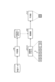
- FIG. 1 is a diagram illustrating an example of a system according to an embodiment.
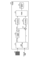
- FIG. 2 is an explanatory diagram illustrating an overview of learning/inference processing.
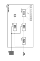
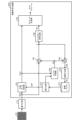
- FIG. 2 is a block diagram showing an example of the overall configuration of a learning device.
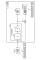
- FIG. 2 is a block diagram showing an example of the internal configuration of an image scanning section.
- FIG. 3 is a diagram showing a specific example of an extraction method for extracting a reference range.
- FIG. 3 is a block diagram showing an example of the internal configuration of a filter processing section. It is a figure showing an example of operation of a learning part.
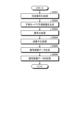
- 3 is a flowchart showing the operational procedure of filter processing. It is a flowchart which shows the operating procedure of learning processing.
- FIG. 1 is a diagram illustrating an example of a system according to an embodiment.
- FIG. 2 is an explanatory diagram illustrating an overview of learning/inference processing.
- FIG. 2 is a block diagram showing an example of the overall configuration of a learning device.
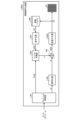
- FIG. 2 is a block diagram showing an example of the overall configuration of an inference device.
- FIG. 3 is a diagram illustrating an example of the operation of the inference section. 3 is a flowchart showing the operational procedure of preprocessing. 7 is a flowchart showing the operating procedure of inference processing.
- FIG. 1 is a block diagram showing an example of the overall configuration of an image encoding device.
- FIG. 2 is a block diagram showing an example of the internal configuration of a prediction mode determining section.
- FIG. 7 is a block diagram showing a modification of the prediction mode determining section.
- FIG. 2 is a block diagram showing an example of the internal configuration of an intra prediction unit. It is a flowchart which shows the operational procedure of image encoding processing.
- FIG. 1 is a block
- FIG. 1 is a block diagram showing an example of the overall configuration of an image decoding device. It is a flowchart which shows the operational procedure of image decoding processing.
- FIG. 3 is a block diagram showing an example (1) of an internal configuration of a filter processing unit according to a modification of the first embodiment.
- FIG. 3 is a block diagram showing an example (2) of an internal configuration of a filter processing unit according to a modification of the first embodiment.
- It is a block diagram showing an example of the whole composition of a learning machine concerning a modification concerning a 1st embodiment.
- FIG. 2 is a block diagram showing an example of the overall configuration of an inference device according to a modification of the first embodiment. It is a block diagram showing an example of the whole composition of a learning machine concerning a modification concerning a 1st embodiment.
- FIG. 7 is a block diagram showing an example of the overall configuration of an image encoding device according to a modification of the second embodiment.
- FIG. 7 is a block diagram showing an example of the overall configuration of an image decoding device according to a modification of the second embodiment.
- FIG. 2 is a block diagram illustrating an example of a hardware configuration of a computer corresponding to an apparatus according to an embodiment and a modification of the present disclosure.
- intra prediction As one of the mechanisms for image compression, a method called intra prediction is used in which prediction is performed for a certain pixel value by referring to surrounding pixels. By transmitting only the difference between the predicted pixel value obtained using this intra-prediction and the actual pixel value, the amount of data can be compressed. For this reason, it is thought that the higher the prediction accuracy of intra prediction, the smaller the difference value becomes, and therefore the compression efficiency can be improved.
- a predicted value is calculated in accordance with a rule-based mathematical model by referring to three pixels surrounding a prediction target pixel.
- prediction performance for diagonal edges and high frequencies is low due to the narrow reference range and the simplicity of the mathematical model.
- Other methods include prediction methods based on machine learning and deep learning.
- the reference range is larger than that of the LOCO-I algorithm, and a more complex mathematical model than that of a rule base is used, so that prediction accuracy can be improved.
- MLP prediction is similar to the LOCO-I algorithm in that it refers to pixels surrounding the prediction target pixel and calculates a predicted value from a group of pixels, but unlike rule-based formula models, it uses pixels that have already been predicted. If so, you can freely set the reference direction and number of references. Therefore, it is also possible to create references that are biased in a specific direction, such as horizontally or vertically.
- the difference between the pixel value and the adjacent left pixel value of the pixel to be predicted is input to the model as a feature quantity, learning and prediction operations are performed, and the prediction result is In some cases, a method of adding adjacent left pixel values is used. This makes it possible to generate a model with the DC component of each pixel canceled, and it is possible to obtain more efficient learning results.
- the conventional technology has a problem of low encoding efficiency (that is, low prediction performance), and there is room for improvement.
- the learning device performs component separation for frequency components included in the reference pixel based on the feature vector of the reference pixel in the vicinity of the prediction target pixel included in the image data. I do.
- a high-frequency vector which is a feature vector of a high-frequency component among the frequency components obtained by component separation
- high-frequency information which is information on a high-frequency component among the frequency components included in a prediction target pixel, are combined.
- a model that outputs a predicted value of a pixel to be predicted is trained.
- FIG. 1 is a diagram illustrating an example of a system according to an embodiment.
- FIG. 1 shows an image processing system 1 as an example of a system according to an embodiment.
- the image processing system 1 includes a learning device 100, an image encoding device 300, and an image decoding device 400.
- the image processing system 1 includes an image processing system 11 that includes an image encoding device 300 and an image decoding device 400.
- an image captured by an imaging device is input to the image encoding device 300, and the image is encoded in the image encoding device 300 to generate encoded data.
- encoded data is transmitted from the image encoding device 300 to the image decoding device 400 as a bit stream.
- an image is generated by decoding the encoded data in the image decoding device 400, and is displayed on a display device (not shown).
- the learning device 100 is an example of a learning device in the present disclosure.
- FIG. 1 shows an example in which the learning device 100 is a server device existing in the cloud for the image processing system 11, but for example, a configuration in which the learning device 100 is installed in the image encoding device 300 as a module may also be adopted. good.
- the inference device 200 is an example of an inference device in the present disclosure. As shown in FIG. 1, the inference device 200 may be installed as a module in an image encoding device 300 and an image decoding device 400.
- the embodiments will be described separately into a first embodiment and a second embodiment. Specifically, in the first embodiment, the configuration/operation of the learning device 100 and the inference device 200 will be described in detail. Furthermore, in the second embodiment, the configuration/operation of an image encoding device 300 and an image decoding device 400 equipped with an inference device 200 will be described in detail.
- FIG. 2 is an explanatory diagram illustrating an overview of learning/inference processing.
- the learning device 100 generates a model used in intra prediction performed by the image encoding device 300 and the image decoding device 400.
- the learning device 100 generates a model with learned parameters by adjusting the parameters of a neural network model.
- the learning device 100 executes a machine learning learning process using learning data. As a result, a trained model is obtained.
- the learning device 100 generates a model using a neural network as a learning algorithm, but the learning algorithm that can be used is not limited to a neural network.
- the learning device 100 may generate a model using a learning algorithm such as a support vector machine, clustering, reinforcement learning, or the like. That is, the learning device 100 may use any machine learning method in model generation.
- the trained model generated by the learning device 100 is used by the inference device 200.
- the inference device 200 uses a machine learning model developed from a learned model by inputting the pixel value vector of a specific reference pixel related to the prediction target pixel X to predict the prediction target pixel X. Calculate the value PxV. More specifically, the inference device 200 inputs the pixel value vector SP(VC) of each reference pixel SP included in the reference range R to the learned model. Then, the inference device 200 intra-predicts the pixel value of the prediction target pixel X by performing predetermined processing on the model predicted value PV output by the model, and obtains the result as the predicted value PxV.
- FIGS. 3 to 7 show main things such as processing units and data flows, and not all of the things shown in FIGS. 3 to 7 are shown. In other words, in the learning device 100, there may be processing units that are not shown as blocks in FIGS. 3 to 7, or processes or data flows that are not shown as arrows or the like in FIGS. 3 to 7. Good too.
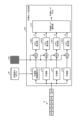
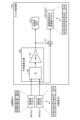
- FIG. 3 is a block diagram showing an example of the overall configuration of the learning device 100.
- the learning device 100 includes a pixel scanning section 101, a filter processing section 102, a difference calculation section 103, and a learning section 104.
- the pixel scanning unit 101 acquires the prediction target pixel X and the reference pixel SP based on the original image data GD and the prediction target coordinates indicating the positional coordinates of the prediction target pixel in the original image data GD. Specifically, the pixel scanning unit 101 extracts one pixel at a position defined by the prediction target coordinates in the original image data GD as the prediction target pixel X. Furthermore, the pixel scanning unit 101 determines a reference range R in the original image data GD based on the prediction target coordinates, and extracts each pixel included in the determined reference range R as a reference pixel SP. Furthermore, the pixel scanning unit 101 calculates a pixel value vector SP (VC) from the reference pixel SP.
- VC pixel value vector SP
- the pixel scanning unit 101 transmits the pixel value vector SP (VC) to the filter processing unit 102 and transmits the prediction target pixel X to the difference calculation unit 103.
- VC pixel value vector
- the filter processing unit 102 Upon receiving the pixel value vector SP(VC), the filter processing unit 102 performs component separation on the frequency components included in the reference pixel SP based on the pixel value vector SP(VC). For example, the filter processing unit 102 calculates filter information from the pixel value vector SP (VC), and uses the calculated filter information to separate high frequency component SP_H and low frequency component SP_L.
- the filter processing unit 102 acquires a high frequency vector SP_H (VC) that is a pixel value vector of the high frequency component SP_H, and transmits the high frequency vector SP_H (VC) to the learning unit 104.
- the high frequency vector SP_H(VC) is used as an explanatory variable EV in the learning process by the learning unit 104.
- the filter processing unit 102 transmits the low frequency component SP_L to the difference calculation unit 103.
- the difference calculation unit 103 subtracts the low frequency component SP_L transmitted by the filter processing unit 102 from the frequency component included in the prediction target pixel X transmitted by the pixel scanning unit 101, thereby calculating the high frequency component of the prediction target pixel X. Get X_H.
- the high frequency component X_H is used as the objective variable OV in the learning process by the learning unit 104.
- the learning unit 104 executes learning processing regarding the neural network model based on learning data in which the high-frequency vector SP_H (VC) is an explanatory variable EV and the high-frequency component X_H is an objective variable OV. Specifically, the learning unit 104 updates parameters (for example, weights and biases) of the neural network model based on the learning data, and generates a model that is a learning result. Thereby, the learning unit 104 obtains a trained model M.
- parameters for example, weights and biases
- FIG. 4 is a block diagram showing an example of the internal configuration of the pixel scanning unit 101.
- the pixel scanning unit 101 includes a reference range extraction unit 105, a pixel value acquisition unit 106, and a pixel value acquisition unit 107.
- the reference range extraction unit 105 extracts the reference range R based on the prediction target coordinates indicating the positional coordinates of the prediction target pixel in the original image data GD. For example, the reference range extraction unit 105 determines relative positional coordinates to the prediction target coordinates, and extracts a pixel group corresponding to the determined positional coordinates as the reference range R.
- FIG. 5 is a diagram showing a specific example of an extraction method for extracting the reference range R.
- FIG. 5 is a diagram showing a specific example of an extraction method for extracting the reference range R.
- the reference range extraction unit 105 can employ any of the three extraction methods shown in FIGS. 5(a) to 5(c).
- the reference range extraction unit 105 extracts one pixel to the left from the position coordinates, one pixel to the top from the position coordinates, as shown in FIG.
- the range corresponding to the three referenced pixels may be extracted as the reference range R.
- the reference range extraction unit 105 adds two pixels (two locations) to the left from the position coordinates, as shown in FIG. 5(b). , move forward one pixel in the upward direction of The range may be extracted as the reference range R.
- the reference range extraction unit 105 adds two pixels (two locations) to the left from the position coordinates, as shown in FIG. 5(c). , advance one pixel in the upward direction of (1 location), 2 pixels on the left and right (4 locations), a total of 12 pixels, and the range of the referenced 12 pixels may be extracted as the reference range R.
- the reference range extraction unit 105 transmits the position coordinates of one candidate pixel (the pixel in which "X" is input) to be acquired as the prediction target pixel X to the pixel value acquisition unit 106, and The reference range R extracted using the method described above is transmitted to the pixel value acquisition unit 107.
- the reference range R can be said to be coordinate information defined by position coordinates relative to the position coordinates of one pixel of the candidate.
- the pixel value acquisition unit 106 acquires one pixel at a position defined by the position coordinates of one candidate pixel in the original image data GD, and determines the acquired pixel as the prediction target pixel X. Further, the pixel value acquisition unit 106 may transmit the prediction target pixel X to the difference calculation unit 103.
- the pixel value acquisition unit 107 acquires pixels at each position defined by the reference range R in the original image data GD, and defines the acquired pixels as reference pixels SP. Furthermore, the pixel value acquisition unit 107 calculates a pixel value vector SP (VC) for each reference pixel SP.
- VC pixel value vector SP
- the pixel value acquisition unit 107 acquires three pixels included in the reference range R, and defines each pixel as a reference pixel SP. Then, the pixel value acquisition unit 107 calculates a pixel value vector SP (VC) for each of the three reference pixels SP.
- VC pixel value vector SP
- the pixel value acquisition unit 107 acquires seven pixels included in the reference range R, and defines each pixel as a reference pixel SP. Then, the pixel value acquisition unit 107 calculates a pixel value vector SP (VC) for each of the seven reference pixels SP.
- VC pixel value vector SP
- the pixel value acquisition unit 107 acquires 12 pixels included in the reference range R, and defines each pixel as a reference pixel SP. Then, the pixel value acquisition unit 107 calculates a pixel value vector SP (VC) for each of the 12 reference pixels SP.
- VC pixel value vector SP
- the pixel value acquisition unit 107 may transmit the pixel value vector SP (VC) to the filter processing unit 102.
- FIG. 6 is a block diagram showing an example of the internal configuration of the filter processing unit 102.
- the filter processing section 102 may be configured to include a representative value calculation section 108 and an addition section 111, and the representative value calculation section 108 may further include a summation section 109 and a division section 110. good.
- the representative value calculation unit 108 calculates a representative value representing the pixel value vector SP (VC) from the pixel value vector SP (VC) transmitted by the pixel value acquisition unit 107, and applies the calculated representative value to the reference pixel SP. It is separated as a low frequency component SP_L among the included frequency components.
- the representative value calculation unit 108 may calculate the average value of the pixel value vector SP(VC) of each reference pixel SP as the representative value representing the pixel value vector SP(VC).
- the representative value calculation unit 108 may calculate the median value of the pixel value vector SP(VC) as the representative value, or may obtain the lowest value of the pixel value vector SP(VC) as the representative value. Good too. In the following description, it will be assumed that the representative value calculation unit 108 calculates the average value of the pixel value vector SP(VC) of each reference pixel SP, and obtains this as the representative value.
- the summation unit 109 calculates the sum ⁇ of the pixel value vector SP(VC) transmitted by the pixel value acquisition unit 107, that is, the pixel value vector SP(VC) of each reference pixel SP.
- the division unit 110 divides the sum ⁇ calculated by the summing unit 109 by the number N of reference pixels SP, thereby obtaining the average value ⁇ /N of the pixel value vector SP (VC) of the reference pixels SP for N pixels. calculate. Then, the dividing unit 110 separates the average value ⁇ /N as a low frequency component SP_L among the frequency components included in the reference pixel SP.
- the division unit 110 adds together the pixel value vectors SP(VC) of the three reference pixels SP.
- the division unit 110 adds together the pixel value vector SP(VC) of the seven reference pixels SP.
- the division unit 110 adds together the pixel value vectors SP(VC) of the 12 reference pixels SP.
- the division unit 110 may transmit the separated low frequency component SP_L to the difference calculation unit 103.
- the low frequency component SP_L is obtained not as a vector but as a mere scalar value.
- the division section 110 may also transmit the separated low frequency component SP_L to the addition section 111.
- the addition unit 111 performs filter processing on the pixel value vector SP (VC) of the reference pixel SP by applying the low frequency component SP_L (average value ⁇ /N) as filter information, so that the pixel value vector SP (VC) of the reference pixel SP is Separate high frequency component SP_H.
- the addition unit 111 may subtract the low frequency component SP_L from the frequency component for each of the N reference pixels SP, and separate the difference obtained by the subtraction as the high frequency component SP_H of the reference pixel SP. Furthermore, based on the pixel value vector SP(VC) of the reference pixel SP to be separated and the high frequency component SP_H of this reference pixel SP, the adding unit 111 adds a high frequency signal that is the pixel value vector of the high frequency component SP_H. A vector SP_H (VC) is calculated and transmitted to the learning unit 104 as an explanatory variable.
- the addition unit 111 calculates the low frequency component SP_L corresponding to the reference pixel SP from the frequency component of the reference pixel SP for each of the three reference pixels SP.
- the subtraction may be performed, and the difference obtained by the subtraction may be separated as the high frequency component SP_H of the reference pixel SP.
- the adding unit 111 generates a high frequency vector SP_H( VC).
- the addition unit 111 calculates the low frequency component SP_L corresponding to the reference pixel SP from the frequency component of the reference pixel SP for each of the seven reference pixels SP. The subtraction may be performed, and the difference obtained by the subtraction may be separated as the high frequency component SP_H of the reference pixel SP. Furthermore, for each of the seven reference pixels SP, the addition unit 111 generates a high-frequency vector SP_H ( VC).
- the addition unit 111 calculates the low frequency component SP_L corresponding to the reference pixel SP from the frequency component of the reference pixel SP for each of the 12 reference pixels SP. The subtraction may be performed, and the difference obtained by the subtraction may be separated as the high frequency component SP_H of the reference pixel SP. Further, for each of the 12 reference pixels SP, the addition unit 111 generates a high frequency vector SP_H( VC).
- the above filter processing described for the filter processing unit 102 is to separate components into two frequency bands. Specifically, the frequency component included in the reference pixel SP is separated into a component corresponding to a high frequency band and a component corresponding to a low frequency band.
- the filter processing unit 102 may separate the components into three frequency bands. Specifically, the frequency component included in the reference pixel SP may be separated into a component corresponding to a high frequency band, a component corresponding to a medium frequency band, and a component corresponding to a low frequency band. A specific example of this example will be described below as a modification.
- the high frequency vector SP_H (VC) obtained by the method of component separation into two frequency bands is continued to be used, and a part of the high frequency component SP_H is separated as a medium frequency component SP_M.
- the medium frequency vector SP_M(VC), which is the pixel value vector of component SP_M, is utilized as an explanatory variable.
- the summation unit 109 calculates the sum ⁇ m of high-frequency vectors SP_H(VC) calculated for each of the N pixels of reference pixels SP. Furthermore, the division unit 110 calculates the average value ⁇ m/N of the high-frequency vector SP_H (VC) of the reference pixels SP for N pixels by dividing the total sum ⁇ m by the number N of reference pixels SP. Then, the division unit 110 separates the average value ⁇ m/N as a second high frequency component SP_H2 among the frequency components included in the reference pixel SP.
- the addition unit 111 performs filtering processing in which the second high frequency component SP_H2 (average value ⁇ m/N) is applied as filter information to the high frequency vector SP_H (VC) of the reference pixel SP.
- a medium frequency component SP_M is separated from each SP.
- the adding unit 111 subtracts the second high frequency component SP_H2 from the frequency component for each of the N reference pixels SP, and separates the difference obtained by the subtraction as the medium frequency component SP_M of the reference pixel SP. It's fine. Further, the addition unit 111 generates a pixel value vector of the medium frequency component SP_H based on the pixel value vector SP(VC) of the reference pixel SP to be separated and the medium frequency component SP_M of this reference pixel SP. A certain medium frequency vector SP_M(VC) is calculated and transmitted to the learning unit 104 as an explanatory variable.
- the medium frequency vector SP_M (VC) is regarded as information equivalent to the high frequency vector SP_H (VC), and is used as an explanatory variable instead of the high frequency vector SP_H (VC).
- FIG. 7 is a diagram showing an example of the operation of the learning unit 104.
- the learning unit 104 executes learning processing using a multi-layer perceptron (MLP) as a neural network model. Specifically, when the addition unit 111 transmits the high frequency vector SP_H(VC) and the difference calculation unit 103 transmits the high frequency component X_H, the learning unit 104 calculates one high frequency vector SP_H(VC) and the high frequency component. A learning process is executed using the pair with X_H as learning data.
- MLP multi-layer perceptron
- the learning unit 104 uses the back error propagation method as shown in FIG. 7 by taking the high frequency vector SP_H (VC) as an explanatory variable and the high frequency component X_H as an objective variable in the learning data. Optimize the parameters (e.g., weights) of each layer using Then, the learning unit 104 generates a learned model M with learned parameters as a learning result obtained by performing the learning process a specified number of times on all input data.
- the learned model M is a model that outputs a predicted value of the prediction target pixel X.
- the learning unit 104 uses the medium frequency vector SP_M (VC), which is the pixel value vector of the medium frequency component SP_H, as the objective variable instead of the high frequency vector SP_H (VC). May be used.
- VC medium frequency vector
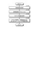
- FIG. 8 is a flowchart showing the operation procedure of filter processing.
- the pixel scanning unit 101 acquires original image data GD (step S801). For example, when an image captured by an imaging device is input to the image encoding device 300, the pixel scanning unit 101 may acquire the input captured image from the image encoding device 300 as original image data.
- the reference range extraction unit 105 extracts the reference range R based on the prediction target coordinates specified in the original image data GD (step S802). For example, the reference range extraction unit 105 determines relative positional coordinates to the prediction target coordinates, and extracts a pixel group corresponding to the determined positional coordinates as the reference range R.
- the pixel scanning unit 101 acquires the prediction target pixel X and the reference pixel SP (step S803).
- the pixel value acquisition unit 106 acquires a pixel at a position defined by the prediction target coordinates in the original image data GD, and defines the acquired pixel as the prediction target pixel X.
- the pixel value acquisition unit 107 acquires pixels at each position defined by the reference range R in the original image data GD, and defines the acquired pixels as reference pixels SP. In the following description, it is assumed that reference pixels SP for N pixels are acquired.
- the pixel value acquisition unit 107 calculates a pixel value vector SP(VC) for each of the N pixels of reference pixels SP (step S804).
- the representative value calculation unit 108 calculates the average value of the pixel value vector SP(VC) of each reference pixel SP as a representative value representing the pixel value vector SP(VC) (step S805).
- the summation unit 109 calculates the sum ⁇ of the pixel value vector SP(VC) of each reference pixel SP.
- the division unit 110 calculates the average value ⁇ /N of the pixel value vector SP(VC) of the reference pixel SP for N pixels by dividing the total sum ⁇ by the number N of pixels of the reference pixel SP.
- the division unit 110 separates the low frequency component SP_L from among the frequency components included in the reference pixel SP based on the average value ⁇ /N (step S806). For example, the division unit 110 separates the average value ⁇ /N as a low frequency component SP_L among the frequency components included in the reference pixel SP. The low frequency component SP_L is transmitted to the difference calculation section 103.
- the adding unit 111 separates the high frequency component SP_H from among the frequency components included in the reference pixel SP based on the low frequency component SP_L (step S807). For example, the adding unit 111 subtracts the low frequency component SP_L from the frequency component for each of the N reference pixels SP, and separates the difference obtained by the subtraction as the high frequency component SP_H of the reference pixel SP.
- the addition unit 111 calculates a high frequency vector SP_H (VC) that is a pixel value vector of the high frequency component SP_H based on the pixel value vector SP (VC) of the reference pixel SP and the high frequency component SP_H of this reference pixel SP. This is then transmitted to the learning unit 104 as an explanatory variable (step S808).
- VC high frequency vector SP_H
- the difference calculation unit 103 subtracts the low frequency component SP_L from the frequency component included in the prediction target pixel X, and separates the difference obtained by the subtraction as the high frequency component X_H of the prediction target pixel X. It is transmitted to the learning unit 104 as a variable (step S809).
- the learning unit 104 uses the high frequency vector SP_H (VC) of the reference pixel SP as the explanatory variable EV, and uses the high frequency component X_H of the prediction target pixel X as the objective A combination of variables OV can be obtained as one learning data.
- SP_H the high frequency vector SP_H (VC) of the reference pixel SP
- EV the explanatory variable
- FIG. 9 is a flowchart showing the operating procedure of the learning process.
- the learning unit 104 acquires learning data in which the high-frequency vector SP_H (VC) is the explanatory variable EV and the high-frequency component X_H is the objective variable OV (step S901).
- the learning unit 104 executes parameter learning processing in the multilayer perceptron (MLP) model (step S902).
- MLP multilayer perceptron
- the learning unit 104 determines whether the search for all original image data GD and all reference images SP has been completed (step S903).
- step S903 If the learning unit 104 determines that the search has not been completed (step S903; No), the process moves to step S901.
- FIGS. 10 and 11 main things such as processing units and data flows are shown, and not all of the things shown in FIGS. 10 and 11 are shown.
- processing units that are not shown as blocks in FIGS. 10 and 11, or there may be processing or data flows that are not shown as arrows or the like in FIGS. Good too.
- the inference device 200 calculates an intra-predicted value by executing inference processing in machine learning. For example, when the pixel value vector SP (VC) of each reference pixel SP included in the reference range R is transmitted, the inference device 200 performs filter processing on the reference pixel SP to convert frequency components included in the reference pixel SP into high-frequency components. The components are separated into component SP_H and low frequency component SP_L. Then, the inference device 200 inputs the high-frequency vector SP_H (VC), which is a pixel value vector of the high-frequency component SP_H, to the trained model M, and calculates the low-frequency component SP_L with respect to the model predicted value PV output from the trained model M. By adding them together, the result is obtained as the final intra predicted value PxV. Below, the inference device 200 will be explained in more detail.
- VC a pixel value vector of the high-frequency component SP_H
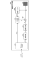
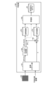
- FIG. 10 is a block diagram showing an example of the overall configuration of the inference device 200.
- the inference device 200 includes a filter processing section 201, an inference section 202, and an addition section 203.
- the filter processing section 201 has the same function as the filter processing section of the learning device 100. For example, when a pixel value vector SP (VC) is transmitted for N pixels of reference pixels SP included in the reference range R, the filter processing unit calculates the reference pixel SP based on the pixel value vector SP (VC). Perform component separation on the frequency components included in . Specifically, the filter processing unit 201 calculates filter information from the pixel value vector SP (VC), and uses the calculated filter information to separate the high frequency component SP_H and the low frequency component SP_L.
- VC pixel value vector SP
- the filter processing unit 201 calculates the average value ⁇ /N of the pixel value vector SP (VC) from the pixel value vector SP (VC) of the reference pixel SP for N pixels, and calculates the calculated average value ⁇ /N. It is separated as a low frequency component SP_L of each reference pixel SP for N pixels.
- the filter processing unit 201 performs filter processing on the pixel value vector SP (VC) of the reference pixel SP by applying the low frequency component SP_L (average value ⁇ /N) as filter information. Separate high frequency component SP_H from each SP. For example, the filter processing unit 201 may subtract the low frequency component SP_L from the frequency component for each of the N reference pixels SP, and may separate the difference obtained by the subtraction as the high frequency component SP_H of the reference pixel SP. .
- the filter processing unit 201 generates a pixel value vector of the high frequency component SP_H based on the pixel value vector SP(VC) of the reference pixel SP to be separated and the high frequency component SP_H of this reference pixel SP.
- a high frequency vector SP_H (VC) is calculated and transmitted to the inference unit 202 as an explanatory variable.
- the inference unit 202 can perform inference processing using the high frequency vector SP_H (VC) of each of the N pixels of reference pixels SP as a target variable.
- the above-mentioned filter processing described for the filter processing unit 201 is to separate components into two frequency bands. Specifically, the frequency component included in the reference pixel SP is separated into a component corresponding to a high frequency band and a component corresponding to a low frequency band.
- the filter processing unit 201 may separate the components into three frequency bands. Specifically, the frequency component included in the reference pixel SP may be separated into a component corresponding to a high frequency band, a component corresponding to a medium frequency band, and a component corresponding to a low frequency band. This method is the same as the method described as a modification of the filter processing unit 201, so a detailed description thereof will be omitted.
- the inference unit 202 When the high-frequency vector SP_H(VC) is transmitted by the filter processing unit 201, the inference unit 202 inputs the high-frequency vector SP_H(VC) to the learned model M as an explanatory variable EV, thereby causing the inference operation to be performed. For example, the inference unit 202 reconstructs the learned model M by inputting the parameters updated by the learning device 100, and inputs the high-frequency vector SP_H (VC) of the objective variable EV to the reconstructed model M. Furthermore, the inference unit 202 transmits the model predicted value PV output from the trained model M to the addition unit 203.
- the inference unit 202 when the middle frequency component SP_M is separated by the filter processing unit 201, the inference unit 202 generates a middle frequency vector SP_M(VC) which is a pixel value vector of the middle frequency component SP_H instead of the high frequency vector SP_H(VC). ) may be used as the objective variable.
- the addition unit 203 is the result of intra-prediction of the pixel value of the prediction target pixel X based on the low frequency component SP_L transmitted by the filter processing unit 201 and the model predicted value PV transmitted by the inference unit 202. Calculate the intra predicted value PxV. For example, the addition unit 203 calculates the intra-predicted value PxV of the prediction target pixel X by performing a restoration operation of adding the low-frequency component SP_L to the model predicted value PV.
- the adding unit 203 calculates that not only the low frequency component SP_L but also the second high frequency component SP_H2 (average value ⁇ m/N) is the model predicted value PV.
- the intra predicted value PxV is calculated by adding them together.
- FIG. 11 is a diagram illustrating an example of the operation of the inference unit 202.
- the inference unit 202 executes inference processing using a multilayer perceptron (MLP) model as a neural network model.
- MLP multilayer perceptron
- the inference unit 202 takes the high-frequency vector SP_H as an explanatory variable and calculates the learned model M, which is a trained neural network model.
- the learned model M outputs a model predicted value PV by a forward propagation type product-sum operation.
- the model predicted value PV is used for the restoration operation by the addition unit 203.
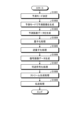
- FIG. 12 is a flowchart showing the operation procedure of preprocessing.
- the preprocessing here refers to filter processing performed as preprocessing of the inference process using the trained model M. That is, preprocessing is processing for obtaining explanatory variables input to the trained model M.
- the filter processing unit 201 determines whether information on the reference pixel SP has been received (step S1201). For example, the filter processing unit 201 determines whether or not the pixel value vector SP (VC) of each of the N pixels included in the reference range R is received as information about the reference pixel SP. While the filter processing unit 201 does not receive information about the reference pixel SP (step S1201), it waits until it receives information about the reference pixel SP.
- the filter processing unit 201 determines whether information on the reference pixel SP has been received (step S1201). For example, the filter processing unit 201 determines whether or not the pixel value vector SP (VC) of each of the N pixels included in the reference range R is received as information about the reference pixel SP. While the filter processing unit 201 does not receive information about the reference pixel SP (step S1201), it waits until it receives information about the reference pixel SP.
- VC pixel value vector SP
- the filter processing unit 201 when the filter processing unit 201 receives information about the reference pixel SP (step S1201; Yes), the filter processing unit 201 sets the pixel value vector SP(VC) of each reference pixel SP as a representative value representing the pixel value vector SP(VC). VC) is calculated (step S1202). For example, the filter processing unit 201 calculates the sum ⁇ of the pixel value vector SP(VC) of each reference pixel SP. Then, the filter processing unit 201 calculates the average value ⁇ /N of the pixel value vector SP(VC) of the reference pixel SP for N pixels by dividing the sum ⁇ by the number N of pixels of the reference pixel SP.
- the filter processing unit 201 separates the low frequency component SP_L from among the frequency components included in the reference pixel SP based on the average value ⁇ /N (step S1203). For example, the filter processing unit 201 separates the average value ⁇ /N as a low frequency component SP_L among the frequency components included in the reference pixel SP. Low frequency component SP_L is transmitted to adder 203.
- the filter processing unit 201 separates the high frequency component SP_H of the frequency components included in the reference pixel SP based on the low frequency component SP_L (step S1204). For example, the filter processing unit 201 subtracts the low frequency component SP_L from the frequency component for each of the N reference pixels SP, and separates the difference obtained by the subtraction as the high frequency component SP_H of the reference pixel SP.
- the addition unit 111 calculates a high frequency vector SP_H (VC) that is a pixel value vector of the high frequency component SP_H based on the pixel value vector SP (VC) of the reference pixel SP and the high frequency component SP_H of this reference pixel SP. This is then transmitted to the inference unit 202 as an explanatory variable EV (step S1205).
- VC high frequency vector SP_H
- the inference unit 202 can obtain, for each of the N pixels of reference pixels SP, the high-frequency vector SP_H(VC) of the reference pixel SP as the explanatory variable EV.
- the operational procedure of the inference process using the explanatory variable EV will be explained.
- FIG. 13 is a flowchart showing the operational procedure of inference processing.
- the inference unit 202 acquires the high-frequency vector SP_H(VC) as an explanatory variable EV (step S1301).
- the inference unit 202 inputs the high-frequency vector SP_H (VC) of the objective variable to the trained model M, which is a neural network (for example, MLP) model whose parameters have been updated by the learning device 100 (Ste S1302).
- the neural network operates and outputs the model predicted value PV. That is, the inference unit 202 obtains the model predicted value PV (step S1303).
- the adding unit 203 calculates the intra-predicted value PxV of the prediction target pixel X by a restoration operation of adding the low-frequency component SP_L to the model predicted value PV (step S1304).
- FIGS. 14 to 18 a configuration example of the image encoding device 300 will be described using FIGS. 14 to 18. Note that in FIGS. 14 to 18, main things such as processing units and data flows are shown, and not all of the things shown in FIGS. 14 to 18 are shown. That is, in the image encoding device 300, there may be processing units that are not shown as blocks in FIGS. 14 to 18, or processes or data flows that are not shown as arrows or the like in FIGS. 14 to 18. You may.
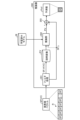
- FIG. 14 is a block diagram showing an example of the overall configuration of the image encoding device 300.
- the image encoding device 300 is equipped with the inference device 200 described in the first embodiment.
- the image encoding device 300 includes a prediction mode determination unit 301, an intra prediction unit 302, a subtraction unit 303, an addition unit 304, a quantization unit 305, an entropy encoding unit 306, and an inverse quantization unit 307. , a reference buffer 308, and a stream generation unit 309.
- the prediction mode determining unit 301 selects the intra prediction mode with the best encoding efficiency based on the cost function value supplied from the intra prediction mode (details will be explained in FIG. 15) of the image encoding device 300. Determine the optimal intra prediction mode.
- the prediction mode determining unit 301 uses the reference pixel SP transmitted by the reference buffer 308 to perform intra prediction processing for all candidate intra prediction modes. Furthermore, the prediction mode determining unit 301 calculates a cost function value for each intra prediction mode, and selects the intra prediction mode in which the calculated cost function value is the minimum, that is, the intra prediction mode in which the coding efficiency is maximized. Determine as the optimal intra prediction mode.
- the intra prediction modes (prediction units) that the image encoding device 300 has are all processing units that perform intra prediction, but the algorithms used are different. Furthermore, the prediction mode determining unit 301 transmits prediction mode information Pinfo, which is information indicating the determined intra prediction mode, to the intra prediction unit 302 and the stream generation unit 309.
- prediction mode information Pinfo which is information indicating the determined intra prediction mode
- the intra prediction unit 302 performs processing related to generation of the predicted image P according to the prediction mode indicated by the prediction mode information Pinfo. For example, the intra prediction unit 302 calculates the intra prediction value of the reference pixel SP by performing intra prediction processing using the prediction mode indicated by the prediction mode information Pinfo and the reference pixel SP transmitted by the reference buffer 308. do. Then, the intra prediction unit 302 generates a predicted image P based on the intra predicted value.
- the intra prediction unit 302 transmits the predicted image P to the subtraction unit 303 and the addition unit 304.
- Adding section 304 adds prediction error data D transmitted by inverse quantization section 307, which will be described later, and predicted image P to generate decoded image data DI (local decoded image). Further, the adding unit 304 accumulates the decoded image data DI in the reference buffer 308.
- Quantization section 305 quantizes prediction error data D and transmits quantized data Q to entropy encoding section 306 and inverse quantization section 307. For example, the quantization unit 305 directly quantizes the luminance value data included in the prediction error data D to obtain quantized data Q.
- Entropy encoding unit 306 Entropy encoding section 306 reversibly encodes quantized data Q and transmits reversibly encoded data RC to stream generation section 309 .
- the dequantization unit 307 dequantizes the quantized data Q.
- the inverse quantization unit 307 derives the prediction error data D by performing an inverse quantization process on the quantized data Q. That is, the dequantization performed by the dequantization unit 307 is the inverse process of the quantization performed by the quantization unit 305, and is the same process as the dequantization performed by the image decoding device 400.
- the dequantization unit 307 transmits the prediction error data D to the addition unit 304.
- the reference buffer 308 accumulates the decoded image data DI generated by the addition unit 304.
- the reference buffer 308 may store the decoded image data DI rearranged in the order of encoding.
- the reference buffer 308 may extract reference pixels SP included in the reference range R from the decoded image data DI, and transmit the extracted reference pixels SP to the prediction mode determining unit 301 and the intra prediction unit 302.
- the reference buffer 308 may also accumulate the original image data GD and transmit this to the subtraction unit 303.
- the stream generation unit 309 multiplexes reversible encoded data RC (for example, bit strings of each syntax element obtained as a result of encoding) and generates an encoded bitstream. Furthermore, the stream generation unit 309 reversibly encodes the prediction mode information Pinfo and adds it to the header information of the encoded bitstream.
- RC reversible encoded data
- Pinfo prediction mode information
- FIG. 15 is a block diagram showing an example of the internal configuration of the prediction mode determining section 301.
- the prediction mode determination unit 301 is configured to include a prediction unit 211, a prediction unit 310, a prediction unit 311, and a prediction unit 312.
- the prediction mode determination unit 301 includes a cost calculation unit #201 corresponding to the prediction unit 211, a cost calculation unit #310 corresponding to the prediction unit 310, and a cost calculation unit corresponding to the prediction unit 311. It further includes a cost calculation unit #312 corresponding to #311, prediction unit 312, and prediction mode selection unit 313.
- the prediction unit 211 is a processing unit that operates in an intra prediction mode for inference processing by the inference device 200 according to the proposed technology of the present disclosure. That is, the prediction unit 211 can essentially be interpreted as the inference device 200. For this reason, the prediction mode determining section 301 is equipped with an inference device 200 that corresponds to the prediction section 211.
- the prediction unit 310, the prediction unit 311, and the prediction unit 312 may be processing units that perform intra prediction processing in any prediction mode.
- the prediction unit 310 performs intra prediction using the adjacent left reference algorithm as the prediction mode.
- the adjacent left reference algorithm is a method of employing the predicted value of the pixel to the left of the pixel X to be predicted as the predicted value of the pixel X to be predicted.
- the prediction unit 311 performs intra prediction using the LOCO-I algorithm as the prediction mode.
- the LOCO-I algorithm refers to the pixel next to the left of the prediction target pixel X, the pixel next to the top of the prediction target pixel This is a method of calculating the predicted value of the target pixel X.
- the diagonal algorithm is a method of calculating a predicted value of the prediction target pixel X in accordance with a rule-based mathematical model by referring to pixels in a diagonal direction with respect to the prediction target pixel X.
- the prediction unit 211 executes a prediction trial in the corresponding intra prediction mode when the original image data GD is input. Specifically, the prediction unit 211 generates a predicted image by applying inference processing by the inference device 200 according to the proposed technology of the present disclosure to the reference pixels SP included in the reference range R.
- the cost calculation unit #201 calculates the cost function value J1 required for the intra prediction process by the prediction unit 211 based on the error between the original image data GD and the predicted image and the cost function. Then, cost calculation unit #201 transmits cost function value J1 to prediction mode selection unit 313.
- the prediction unit 310 performs a prediction trial in a corresponding intra prediction mode when the original image data GD is input. Specifically, the prediction unit 310 generates a predicted image by applying inference processing using the adjacent left reference algorithm to the reference pixels SP included in the reference range R.
- the cost calculation unit #310 calculates a cost function value J2 required for intra prediction processing by the prediction unit 310 based on the error between the original image data GD and the predicted image and the cost function. Then, cost calculation unit #310 transmits cost function value J2 to prediction mode selection unit 313.
- the prediction unit 311 executes a prediction trial in the corresponding intra prediction mode when the original image data GD is input. Specifically, the prediction unit 311 generates a predicted image by applying inference processing using the LOCO-I algorithm to the reference pixels SP included in the reference range R.
- the cost calculation unit #311 calculates a cost function value J3 required for intra prediction processing by the prediction unit 311 based on the error between the original image data GD and the predicted image and the cost function. Then, cost calculation unit #311 transmits cost function value J3 to prediction mode selection unit 313.
- the prediction unit 312 executes a prediction trial in a corresponding intra prediction mode when the original image data GD is input. Specifically, the prediction unit 312 generates a predicted image by applying inference processing using a diagonal algorithm to reference pixels SP included in the reference range R.
- the cost calculation unit #312 calculates a cost function value J4 required for intra prediction processing by the prediction unit 312 based on the error between the original image data GD and the predicted image and the cost function. Then, cost calculation unit #312 transmits cost function value J4 to prediction mode selection unit 313.
- the prediction mode selection unit 313 selects the optimal intra prediction mode with the best encoding efficiency from among all intra prediction modes that are candidates. According to the example of FIG. 15, the prediction mode selection unit 313 selects four types of intra prediction modes, namely, a prediction mode corresponding to the prediction unit 211, a prediction mode corresponding to the prediction unit 310, and a prediction mode corresponding to the prediction unit 311. , the optimal intra prediction mode with the best encoding efficiency is selected from among the prediction modes corresponding to the prediction unit 312.
- the prediction mode selection unit 313 compares the cost function value J1, the cost function value J2, the cost function value J3, and the cost function value J4, and selects the prediction mode with the lowest value as the optimal one with the best encoding efficiency. It may be selected as an intra prediction mode. Then, the prediction mode selection unit 313 transmits prediction mode information Pinfo indicating the selected intra prediction mode to the intra prediction unit 302 and the stream generation unit 309.
- the prediction mode determination unit 301 may include only the prediction unit 211 including the inference device 200 according to the proposed technology of the present disclosure.
- the prediction mode determining unit 301 may include a prediction unit that supports algorithms other than the adjacent left reference algorithm, the LOCO-I algorithm, and the diagonal direction algorithm.
- the prediction mode determining unit 301 may select an intra prediction mode based on the calculation amount of each of the prediction unit 211, the prediction unit 310, the prediction unit 311, and the prediction unit 312. For example, cost calculation unit #201 calculates the amount of calculation by the prediction unit 211, cost calculation unit #310 calculates the amount of calculation by prediction unit 310, cost calculation unit #311 calculates the amount of calculation by prediction unit 311, The cost calculation unit #312 calculates the amount of calculation performed by the prediction unit 312. Then, the prediction mode selection unit 313 may compare each calculation amount and select the prediction mode with the lowest value as the optimal intra prediction mode.
- FIG. 15 a typical example of operation by the prediction mode determination unit 301 has been described.
- the prediction mode determining unit 301 may determine the intra prediction mode using a method different from the example in FIG. 15 .
- the prediction mode determining unit 301 may determine the optimal intra prediction mode with the best coding efficiency among the intra prediction modes based on RD (Rate Distortion) cost.
- RD Red Distortion
- FIG. 16 is a block diagram showing a modification of the prediction mode determining section 301. Note that the internal configuration example of the prediction mode determining unit 301 according to the modification may be the same as the example shown in FIG. 15, and a description thereof will be omitted.
- the difference image is quantized and variable-length encoded for the intra prediction mode that is a candidate.
- the bit rate and coding distortion are then calculated for each intra prediction mode.
- each processing unit included in the prediction mode determining unit 301 operates as follows.
- the prediction unit 211 executes a prediction trial in the corresponding intra prediction mode when the original image data GD is input. Specifically, the prediction unit 211 generates a predicted image by applying inference processing by the inference device 200 according to the proposed technology of the present disclosure to the reference pixels SP included in the reference range R.
- the cost calculation unit #201 calculates the bit rate Rate used when encoding the error between the original image data GD and the predicted image P and the prediction mode information, and also calculates the encoding distortion D. The cost calculation unit #201 then calculates the Lagrange multiplier ⁇ calculated according to the quantization parameter selected during encoding, the bit rate Rate, and the Lagrange cost function defined by the encoding distortion D. , calculate the RD cost C1.
- the prediction unit 310 performs a prediction trial in a corresponding intra prediction mode when the original image data GD is input. Specifically, the prediction unit 310 generates a predicted image by applying inference processing using the adjacent left reference algorithm to the reference pixels SP included in the reference range R.
- the cost calculation unit #310 calculates the bit rate Rate used when encoding the error between the original image data GD and the predicted image and the prediction mode information, and also calculates the encoding distortion D. Then, cost calculation unit #310 calculates RD cost C2 based on a Lagrange cost function defined by Lagrange multiplier ⁇ , bit rate Rate, and encoding distortion D.
- the prediction unit 311 executes a prediction trial in the corresponding intra prediction mode when the original image data GD is input. Specifically, the prediction unit 311 generates a predicted image by applying inference processing using the LOCO-I algorithm to the reference pixels SP included in the reference range R.
- the cost calculation unit #311 calculates the bit rate Rate used when encoding the error between the original image data GD and the predicted image and the prediction mode information, and also calculates the encoding distortion D. Then, cost calculation unit #311 calculates RD cost C3 based on a Lagrange cost function defined by Lagrange multiplier ⁇ , bit rate Rate, and encoding distortion D.
- the prediction unit 312 executes a prediction trial in a corresponding intra prediction mode when the original image data GD is input. Specifically, the prediction unit 312 generates a predicted image by applying inference processing using a diagonal algorithm to reference pixels SP included in the reference range R.
- the cost calculation unit #312 calculates the bit rate Rate used when encoding the error between the original image data GD and the predicted image and the prediction mode information, and also calculates the encoding distortion D. Then, cost calculation unit #312 calculates RD cost C4 based on a Lagrange cost function defined by Lagrange multiplier ⁇ , bit rate Rate, and encoding distortion D.
- the prediction mode selection unit 313 may compare RD cost C1, RD cost C2, RD cost C3, and RD cost C4, and select the prediction mode with the lowest value as the optimal intra prediction mode with the best encoding efficiency. Then, the prediction mode selection unit 313 transmits prediction mode information Pinfo indicating the selected intra prediction mode to the intra prediction unit 302 and the stream generation unit 309.
- FIG. 17 is a block diagram showing an example of the internal configuration of the intra prediction unit 302.
- the example in FIG. 17 corresponds to FIG. 15 (also in FIG. 16). Therefore, the intra prediction unit 302 includes a prediction unit similar to the prediction mode determination unit 301. That is, the intra prediction unit 302 can operate in the same four types of prediction modes as the prediction mode determination unit 301.
- the intra prediction unit 302 includes a prediction unit 211, a prediction unit 310, a prediction unit 311, and a prediction unit 312.
- the intra prediction unit 302 further includes a multiplexer 314 and a multiplexer 315.
- intra prediction unit 302 when the original image data GD is input, intra prediction is performed in the prediction mode determined by the prediction mode determination unit 301, and an intra prediction value is output.
- Multiplexer 3114 When the reference pixel SP included in the reference range R in the original image data GD is input, the multiplexer 314 performs prediction specified by the prediction mode information Pinfo based on the prediction mode information Pinfo transmitted by the prediction mode determining unit 301. Identify the mode. Then, the multiplexer 314 causes the intra prediction unit corresponding to the specified prediction mode among the prediction unit 211, the prediction unit 310, the prediction unit 311, and the prediction unit 312 to execute the intra prediction process according to the prediction mode. . For example, the multiplexer 314 causes the intra prediction unit corresponding to the specified prediction mode to perform intra prediction processing by transmitting the reference pixel SP.
- the multiplexer 314 transmits the reference pixel SP to the prediction unit 211 (inference unit 200).
- the prediction unit 211 executes intra prediction processing using the trained model M.
- the operation details of the prediction unit 211 are as described for the inference unit 200, for example, with reference to FIGS. 10 to 13. Further, the predicted value calculated by the intra prediction process is transmitted to the multiplexer 315.
- Multiplexer 315 Upon receiving the predicted value, the multiplexer 315 outputs the received predicted value as an intra predicted value.
- FIG. 18 is a flowchart showing the operational procedure of image encoding processing.
- the prediction mode determining unit 301 determines an intra prediction mode to be used for generating a predicted image from among candidate intra prediction modes (step S1801). Through this processing, prediction processing is performed in all candidate intra prediction modes, and cost function values in all candidate prediction modes are calculated. Then, the optimal intra prediction mode is determined based on the calculated cost function value. Prediction mode information Pinfo indicating the optimal intra prediction mode is transmitted to the intra prediction section 302 and the stream generation section 309.
- the prediction mode determining unit 301 may refer to the reference buffer 308, check the presence or absence of a locally decoded image, and determine the intra prediction mode based on the check result. For example, if no locally decoded images are stored in the reference buffer 308, the prediction mode determining unit 301 may determine any predetermined intra prediction mode as the initial mode used to generate the predicted image. On the other hand, when locally decoded images are accumulated in the reference buffer 308, the prediction mode determining unit 301 may determine the optimal intra prediction mode based on the cost function value, as described above.
- the intra prediction unit 302 performs processing related to the generation of the predicted image P according to the prediction mode indicated by the prediction mode information Pinfo (step S1802). For example, the intra prediction unit 302 calculates the intra prediction value of the reference pixel SP by performing intra prediction processing using the prediction mode indicated by the prediction mode information Pinfo and the reference pixel SP transmitted by the reference buffer 308. do. Then, the intra prediction unit 302 generates a predicted image P based on the intra predicted value. This predicted image P is transmitted to a subtraction section 303 and an addition section 304.
- the subtraction unit 303 calculates prediction error data D (step S1803). For example, the subtraction unit 303 calculates prediction error data D that is the difference between the predicted image P generated by the intra prediction unit 302 and the original image data GD. Prediction error data D is transmitted to quantization section 305.
- the quantization unit 305 performs quantization processing (step S1804). For example, the quantization unit 305 directly quantizes the luminance value data included in the prediction error data D, thereby obtaining quantization data Q as a quantization value. For example, the quantization unit 305 divides the prediction error data D, and among the quantized values obtained by quantizing each prediction error data D after the division, the lower quantized data Q is rounded down, and the higher quantized data Q may be transmitted to the entropy encoding section 306 and the inverse quantization section 307.
- the dequantization unit 307 performs dequantization processing (step S1805). Through the inverse quantization process, the quantized data Q is returned to the value before quantization by the quantization unit 305, that is, the prediction error data D. That is, the dequantization unit 307 restores the prediction error data D by performing dequantization processing on the quantized data Q. Further, the restored prediction error data D is transmitted to the adding section 304.
- the addition unit 304 generates decoded image data DI (step S1806). For example, the adding unit 304 adds the prediction error data D and the predicted image P generated by the intra prediction unit 302 to generate decoded image data DI (local decoded image).
- the decoded image data DI is stored in the reference buffer 308.
- the entropy encoding unit 306 performs reversible encoding processing (step S1807). Specifically, the entropy encoding unit 306 reversibly encodes the quantized data Q. That is, reversible encoding such as variable length encoding or arithmetic encoding is performed on the quantized data Q, and the data is compressed. The reversible encoded data RC is transmitted to the stream generation section 309.
- the stream generation unit 309 performs stream generation processing (step S1808). For example, the stream generation unit 309 multiplexes lossless encoded data RC and generates an encoded bitstream. Furthermore, the stream generation unit 309 reversibly encodes the prediction mode information Pinfo and adds it to the header information of the encoded bitstream.
- the reference buffer 308 performs transmission based on the decoded image data DI (step S1809). For example, when the reference buffer 308 has accumulated decoded image data DI, the reference pixel SP included in the reference range R is extracted from the decoded image data DI, and the extracted reference pixel SP is transferred to the prediction mode determining unit 308. and transmits it to the intra prediction unit 302.
- FIG. 19 the main things such as a processing part and a flow of data are shown, and what is shown in FIG. 19 is not necessarily all. That is, in the image decoding device 400, there may be a processing unit that is not shown as a block in FIG. 19, or there may be a process or a data flow that is not shown as an arrow or the like in FIG.
- FIG. 19 is a block diagram showing an example of the overall configuration of image decoding device 400.
- the image decoding device 400 is equipped with the inference device 200 described in the first embodiment.
- the image decoding device 400 is configured to include a stream expansion section 401, a decoding section 402, an inverse quantization section 403, an intra prediction section 404, an addition section 405, and a reference buffer 406.
- the stream decompression unit 401 receives the encoded bitstream as input and separates encoded information using a method corresponding to the encoding method of the entropy encoding unit 306 of the image encoding device 300. For example, the stream decompression unit 401 derives parameters by variable length decoding of lossless encoded data RC from a bit string of an encoded bitstream.
- the parameters include header information, prediction mode information Pinfo, quantized data Q, and the like.
- the stream expansion unit 401 transmits the prediction mode information Pinfo to the intra prediction unit 404, and transmits the quantized data Q to the decoding unit 402.
- the decoding section 402 decodes the quantized data Q using a method corresponding to the encoding method of the entropy encoding section 306.
- the dequantization unit 403 dequantizes the quantized data Q decoded by the decoding unit 402 using a method corresponding to the quantization method of the quantization unit 305 of the image encoding device 300. As a result, prediction error data D is obtained. Therefore, the dequantization section 403 transmits the prediction error data D to the addition section 405.
- the intra prediction unit 404 performs processing related to the generation of the predicted image P according to the prediction mode indicated by the prediction mode information Pinfo transmitted by the stream expansion unit 401. For example, the intra prediction unit 404 calculates the intra prediction value of the reference pixel SP by performing intra prediction processing using the prediction mode indicated by the prediction mode information Pinfo and the reference pixel SP transmitted by the reference buffer 406. do. Then, the intra prediction unit 302 generates a predicted image P based on the intra predicted value. Further, the intra prediction unit 404 transmits the predicted image P to the addition unit 405.
- the intra prediction unit 404 has the same configuration as the intra prediction unit 302 described above.
- an example internal configuration of the intra prediction unit 404 may be the same as that of the intra prediction unit 302. That is, the internal configuration example of the intra prediction unit 404 may be the same as that in FIG. 17.
- the intra prediction unit 404 includes a prediction unit 211, a prediction unit 310, a prediction unit 311, and a prediction unit 312, and also includes a multiplexer 314 and a multiplexer 315.
- the prediction mode information Pinfo specifies the inference process according to the proposed technology of the present disclosure
- the reference pixel SP is transmitted to the prediction unit 211 (inference unit 200), and the prediction unit 211 Intra prediction processing using the trained model M is executed.
- the adding unit 405 adds the prediction error data D and the predicted image P to generate decoded image data DI (local decoded image). Further, the adding unit 405 causes the decoded image data DI to be accumulated in the reference buffer 406.
- Reference buffer 406 accumulates decoded image data DI generated by adder 405.
- the reference buffer 406 may store the decoded image data DI rearranged in the order of encoding. Further, the reference buffer 406 may extract reference pixels SP included in the reference range R from the decoded image data DI, and transmit the extracted reference pixels SP to the intra prediction unit 404.
- the decoded image data DI may be rearranged from the decoding order to the playback order, and the rearranged decoded image data DI group may be output to the outside of the image decoding device 400 as moving image data.
- FIG. 20 is a flowchart showing the operation procedure of image decoding processing.
- the stream decompression unit 401 When the encoded bitstream is input, the stream decompression unit 401 performs reversible decoding processing (step S2001). Stream decompression unit 401 decodes the encoded bitstream. Through such processing, quantized data Q encoded by entropy encoding section 306 is obtained and transmitted to decoding section 402. Furthermore, the stream decompression unit 401 performs reversible decoding of prediction mode information included in the header information of the encoded bitstream, and transmits the obtained prediction mode information Pinfo to the intra prediction unit 404.
- the intra prediction unit 404 performs processing related to the generation of the predicted image P according to the prediction mode indicated by the prediction mode information Pinfo (step S2002). For example, the intra prediction unit 404 calculates the intra prediction value of the reference pixel SP by performing intra prediction processing using the prediction mode indicated by the prediction mode information Pinfo and the reference pixel SP transmitted by the reference buffer 406. do. Then, the intra prediction unit 404 generates a predicted image P based on the intra predicted value. Predicted image P is transmitted to addition section 405.
- the decoding unit 402 performs decoding processing (step S2003). Specifically, the decoding unit 402 decodes the quantized data Q. The decoded quantized data Q is transmitted to the inverse quantization section 403.
- the dequantization unit 403 performs dequantization processing (step S2004). Specifically, the dequantization unit 403 dequantizes the quantized data Q decoded by the decoding unit 402 with characteristics corresponding to the characteristics of the quantization unit 305 of the image encoding device 300. Through the inverse quantization process, the quantized data Q is returned to the value before quantization, that is, the prediction error data D. That is, the dequantization unit 403 restores the prediction error data D by performing dequantization processing on the quantized data Q. The restored prediction error data D is transmitted to the adding section 405.
- the addition unit 405 generates decoded image data DI (step S2005). For example, the adding unit 405 adds the prediction error data D and the predicted image P generated by the intra prediction unit 404 to generate decoded image data DI (local decoded image). This decodes the original image.
- the decoded image data DI is stored in the reference buffer 308.
- the reference buffer 406 stores the decoded image data DI (step S2006).
- FIG. 21 is a block diagram showing an example (1) of the internal configuration of the filter processing unit 102 according to a modification of the first embodiment.
- the representative value calculation unit 108 extracts a predetermined M pixels from out-of-range pixels NP, which are pixels outside the reference range R, and adds the extracted M pixels out-of-range pixels NP to the summation unit. 109. Note that the process of extracting M pixels of out-of-range pixels NP may be performed by the pixel scanning unit 101.
- the summation unit 109 calculates the sum ⁇ by adding together the pixel value vectors SP(VC) of each of the N pixels of reference pixels SP.
- the summing unit 109 generates a pixel value vector SP(VC) for each of the reference pixels SP for N pixels, and a pixel value vector SP(VC) for each of the out-of-range pixels NP for M pixels.
- the total sum ⁇ is calculated by taking the total sum of all.
- the division unit 110 calculates the average value ⁇ /N+M by dividing the total sum ⁇ calculated by the summing unit 109 by the total number of pixels N+M.
- the division unit 110 determines this average value ⁇ /N+M as the average value of the pixel value vector SP(VC) of the reference pixels SP for N pixels. That is, the division unit 110 separates the average value ⁇ /N+M as a low frequency component SP_L of the frequency components included in the reference pixel SP.
- the adding unit 111 performs filtering processing applying the low frequency component SP_L (average value ⁇ /N+M) as filter information to the pixel value vector SP (VC) of the reference pixel SP, thereby reducing the reference value for N pixels.
- a high frequency component SP_H is separated from each pixel SP.
- the addition unit 111 may subtract the low frequency component SP_L from the frequency component for each of the N reference pixels SP, and separate the difference obtained by the subtraction as the high frequency component SP_H of the reference pixel SP. Furthermore, based on the pixel value vector SP(VC) of the reference pixel SP to be separated and the high frequency component SP_H of this reference pixel SP, the adding unit 111 adds a high frequency signal that is the pixel value vector of the high frequency component SP_H. A vector SP_H (VC) is calculated and transmitted to the learning unit 104 as an explanatory variable. On the other hand, the pixel value vector NP(VC) of the surrounding pixel NP is not transmitted.
- FIG. 22 is a block diagram showing an example (2) of the internal configuration of the filter processing unit 102 according to a modification of the first embodiment.
- the representative value calculation unit 108 extracts a predetermined L pixels from among the N pixels of reference pixels SP included in the reference range R, and extracts the extracted L pixels of reference pixels SP. is input to the summation section 109. Note that the process of extracting the reference pixels SP for L pixels may be performed by the pixel scanning unit 101.
- the summation unit 109 calculates the sum ⁇ by adding together the pixel value vectors SP(VC) of each of the N pixels of reference pixels SP.
- the summation unit 109 calculates the sum ⁇ by adding together the pixel value vectors SP(VC) of the reference pixels SP for L pixels.
- the division unit 110 calculates the average value ⁇ /L by dividing the sum ⁇ calculated by the summing unit 109 by the number of pixels L.
- the division unit 110 determines this average value ⁇ /L as the average value of the pixel value vector SP(VC) of the reference pixels SP for N pixels. That is, the division unit 110 separates the average value ⁇ /L as a low frequency component SP_L among the frequency components included in the reference pixel SP.
- the addition unit 111 performs filter processing on the pixel value vector SP (VC) of the reference pixel SP by applying the low frequency component SP_L (average value ⁇ /L) as filter information, thereby reducing the reference value for N pixels.
- a high frequency component SP_H is separated from each pixel SP.
- the addition unit 111 may subtract the low frequency component SP_L from the frequency component for each of the N reference pixels SP, and separate the difference obtained by the subtraction as the high frequency component SP_H of the reference pixel SP. Furthermore, based on the pixel value vector SP(VC) of the reference pixel SP to be separated and the high frequency component SP_H of this reference pixel SP, the adding unit 111 adds a high frequency signal that is the pixel value vector of the high frequency component SP_H. A vector SP_H (VC) is calculated and transmitted to the learning unit 104 as an explanatory variable EV.
- the filter processing unit 102 converts the frequency components included in the reference pixel SP into high frequency components SP_H using filter information calculated from the pixel value vector SP (VC).
- VC pixel value vector SP
- An example has been shown in which the low frequency component SP_L is separated and the high frequency vector SP_H (VC) is transmitted to the learning unit 104.
- the high frequency vector SP_H(VC) is used as the explanatory variable EV in the learning process by the learning unit 104.
- the feature quantity used as the explanatory variable EV is not limited to the high frequency vector SP_H (VC).
- FIG. 23 is a block diagram showing an example of the overall configuration of the learning device 100 according to a modification of the first embodiment.
- the filter processing unit 102 only transmits the low frequency component SP_L separated from the frequency component included in the reference pixel SP to the difference calculation unit 103.
- the filter processing unit 102 may also transmit the low frequency component SP_L separated from the frequency component included in the reference pixel SP to the learning unit 104.
- the learning unit 104 combines the low frequency component SP_L with the high frequency component X_H transmitted from the filter processing unit 102 as the explanatory variable EV.
- the learning unit 104 executes learning processing regarding the neural network model based on learning data in which the explanatory variable EV is a feature amount in which the high frequency component X_H and the low frequency component SP_L are combined.
- FIG. 24 is a block diagram showing an example of the overall configuration of the inference device 200 according to a modification of the first embodiment.
- the filter processing unit 201 only transmits the low frequency component SP_L separated from the frequency component included in the reference pixel SP to the addition unit 203.
- the filter processing unit 201 may also transmit the low frequency component SP_L separated from the frequency component included in the reference pixel SP to the inference unit 202.
- the inference unit 202 combines the low frequency component SP_L with the high frequency component X_H transmitted from the filter processing unit 102 as the explanatory variable EV. That is, the inference unit 202 executes the inference operation by inputting the feature quantity, which is a combination of the high frequency component X_H and the low frequency component SP_L, to the learned model M as the explanatory variable EV.
- FIG. 25 is a block diagram showing an example of the overall configuration of the learning device 100 according to a modification of the first embodiment.
- FIG. 25 shows a learning device 100A as an example of the learning device 100 according to the modification.
- the learning device 100 further includes a quantization section 112 compared to the learning device 100 of FIG.
- Quantization unit 112 When the original image data GD is input, the quantization unit 112 generates image data QGD by quantizing the pixels forming the input original image data GD. Further, the quantization unit 112 transmits the generated image data QGD to the pixel scanning unit 101.
- the pixel scanning unit 101 extracts one pixel at a position defined by the prediction target coordinates in the image data QGD as the prediction target pixel X. Furthermore, the pixel scanning unit 101 determines a reference range R in the image data QGD based on the prediction target coordinates, and extracts each pixel included in the determined reference range R as a reference pixel SP. The pixel value in the reference pixel SP is quantized.
- the high frequency vector SP_H (VC), the low frequency component SP_L, and the high frequency component X_H all become information based on the quantized data QD, that is, the learning
- the learning process in the device 100 is based on the quantized data QD.
- the processes of the image encoding device 300 equipped with the inference device 200 and the image decoding device 400 equipped with the inference device 200 are also changed to processes corresponding to quantization. This point will be explained in more detail below using FIGS. 26 and 27.
- FIG. 26 is a block diagram showing an example of the overall configuration of an image encoding device 300 according to a modification of the second embodiment.
- FIG. 26 shows an image encoding device 300A as an example of an image encoding device 300 according to a modification.
- the image encoding device 300A further includes a quantization section 311, a quantization section 312, and a reference buffer 313, compared to the image encoding device 300 of FIG.
- the image encoding device 300A includes an inverse quantization section 307A instead of the quantization section 305 and the inverse quantization section 307 included in the image encoding device 300 of FIG. That is, in the image encoding device 300A, the quantization unit 305 and the inverse quantization unit 307 may be eliminated.
- Quantization unit 3111 When the original image data GD is input, the quantization unit 311 generates image data QGD by quantizing the pixels forming the input original image data GD. Further, the quantization unit 311 transmits the image data QGD to the prediction mode determination unit 301 and the subtraction unit 303.
- the quantization unit 312 performs quantization processing on the reference pixel SP transmitted by the reference buffer 313. Specifically, the quantization unit 312 quantizes the reference pixel SP to obtain the reference pixel QSP as the quantized reference pixel SP. Further, the quantization unit 312 transmits the reference pixel QSP to the prediction mode determination unit 301 and the intra prediction unit 302.
- the reference buffer 313 stores decoded image data DI generated by an inverse quantization unit 307A, which will be described later.
- the reference buffer 313 may store the decoded image data DI rearranged in the order of encoding. Further, the reference buffer 313 may extract reference pixels SP included in the reference range R from the decoded image data DI, and transmit the extracted reference pixels SP to the quantization unit 312.
- the prediction mode determination unit 301 uses the reference pixel QSP transmitted by the quantization unit 312 to perform intra prediction processing for all candidate intra prediction modes. Furthermore, the prediction mode determining unit 301 calculates a cost function value for each intra prediction mode, and selects the intra prediction mode in which the calculated cost function value is the minimum, that is, the intra prediction mode in which the coding efficiency is maximized. Determine as the optimal intra prediction mode. Furthermore, the prediction mode determining unit 301 transmits prediction mode information Pinfo, which is information indicating the determined intra prediction mode, to the intra prediction unit 302 and the stream generation unit 309.
- Pinfo prediction mode information
- the intra prediction unit 302 performs processing related to the generation of the predicted image QP according to the prediction mode indicated by the prediction mode information Pinfo. For example, the intra prediction unit 302 performs intra prediction processing using the prediction mode indicated by the prediction mode information Pinfo and the reference pixel QSP transmitted by the quantization unit 312, thereby calculating the intra prediction value of the reference pixel QSP. calculate. Then, the intra prediction unit 302 generates a predicted image QP based on the intra predicted value. The predicted image QP corresponds to the quantized predicted image P generated by the intra prediction unit 302 in FIG. 14.
- the intra prediction unit 302 transmits the predicted image QP to the subtraction unit 303 and the addition unit 304.
- the quantization unit 305 obtains quantized data Q by quantizing the prediction error data D.
- the prediction error data Q is calculated from the quantized information, specifically, the image data QGD and the predicted image QP, so it is essentially the same as that described in FIG. 14. Corresponds to quantized data Q.
- the subtraction unit 303 transmits the prediction error data Q to the addition unit 304 and the entropy encoding unit 306.
- the adding unit 304 adds the prediction error data Q and the predicted image QP to generate decoded image data QDI in a quantized state.
- the dequantization unit 307 restores the prediction error data D by dequantizing the quantized data Q
- the addition unit 304 restores the prediction error data D and the predicted image P.
- the decoded image data DI was generated by adding the above.
- the addition unit 304 is configured to temporarily quantize information from the quantized state, specifically, the prediction error data Q and the predicted image QP.
- the decoded image data QDI in the state is generated. Further, the addition section 304 transmits the decoded image data QDI to the dequantization section 307A.
- the decoded image data QDI is image data that has been quantized. Therefore, the dequantization unit 307A dequantizes the decoded image data QDI. Specifically, the dequantization unit 307A performs dequantization processing on the decoded image data QDI to obtain original decoded image data DI in a dequantized state. Further, the dequantization unit 307A stores the decoded image data DI in the reference buffer 313.
- Entropy encoding unit 306 Entropy encoding section 306 reversibly encodes prediction error data Q (quantized data Q) and transmits reversibly encoded data RC to stream generation section 309 .
- the stream generation unit 309 multiplexes the reversible encoded data RC and generates an encoded bitstream. Furthermore, the stream generation unit 309 reversibly encodes the prediction mode information Pinfo and adds it to the header information of the encoded bitstream.
- FIG. 27 is a block diagram showing an example of the overall configuration of an image decoding device 400 according to a modification of the second embodiment.
- FIG. 27 shows an image decoding device 400A as an example of an image decoding device 400 according to a modification.
- Image decoding device 400A further includes a quantization unit 407, as compared to image decoding device 400 in FIG.
- the image decoding device 400A includes an inverse quantization section 403A instead of the inverse quantization section 403 included in the image encoding device 300 in FIG. That is, in the image decoding device 400A, the inverse quantization unit 403 may be abolished.
- the stream expansion unit 401 receives the encoded bitstream as input and separates encoded information using a method corresponding to the encoding method of the entropy encoding unit 306 of the image encoding device 300A.
- the stream decompression unit 401 derives parameters by variable length decoding of lossless encoded data RC from a bit string of an encoded bitstream.
- the parameters include header information, prediction mode information Pinfo, prediction error data Q (quantized data Q), and the like.
- the stream expansion unit 401 transmits the prediction mode information Pinfo to the intra prediction unit 404, and transmits the prediction error data Q to the decoding unit 402.
- the decoding unit 402 decodes the prediction error data Q using a method corresponding to the encoding method of the entropy encoding unit 306.
- An example has been shown in which the quantized data Q is decoded and the inverse quantization unit 403 inversely quantizes the quantized data Q.
- the prediction error data Q decoded by the decoding section 402 is transmitted as is to the addition section 405 without being dequantized.
- Quantization unit 407 performs quantization processing on the reference pixel SP transmitted by the reference buffer 406. Specifically, the quantization unit 312 quantizes the reference pixel SP to obtain the reference pixel QSP as the quantized reference pixel SP. Further, the quantization unit 407 transmits the reference pixel QSP to the intra prediction unit 404.
- the intra prediction unit 404 performs processing related to generation of the predicted image QP according to the prediction mode indicated by the prediction mode information Pinfo. For example, the intra prediction unit 404 performs intra prediction processing using the prediction mode indicated by the prediction mode information Pinfo and the reference pixel QSP transmitted by the quantization unit 407, thereby calculating the intra prediction value of the reference pixel QSP. calculate. Then, the intra prediction unit 404 generates a predicted image QP based on the intra predicted value. The predicted image QP corresponds to the quantized predicted image P generated by the intra prediction unit 404 in FIG. 19. In addition, the intra prediction unit 404 transmits the predicted image QP to the addition unit 405.
- Adding unit 405 adds prediction error data Q and predicted image QP to generate decoded image data QDI in a quantized state.
- the dequantization unit 403 acquires the prediction error data D by dequantizing the quantized data Q decoded by the decoding unit 402, and the addition unit 304 acquires the prediction error data D. Error data D and predicted image P were added to generate decoded image data DI.
- the addition unit 405 is configured to temporarily quantize information from the quantized state, specifically, the prediction error data Q and the predicted image QP.
- the decoded image data QDI in the state is generated. Further, the addition unit 405 transmits the decoded image data QDI to the dequantization unit 403A.
- the decoded image data QDI is image data that has been quantized. Therefore, the dequantization unit 404A dequantizes the decoded image data QDI. Specifically, the dequantization unit 404A performs dequantization processing on the decoded image data QDI to obtain original decoded image data DI in a dequantized state. Further, the dequantization unit 404A stores the decoded image data DI in the reference buffer 406.
- the reference buffer 406 stores decoded image data DI generated by the inverse quantization unit 404A.
- the reference buffer 406 may store the decoded image data DI rearranged in the order of encoding.
- the reference buffer 406 may extract reference pixels SP included in the reference range R from the decoded image data DI, and transmit the extracted reference pixels SP to the quantization unit 407.
- the prediction accuracy is higher than that of conventional machine learning algorithms, especially for edges and high frequency components. can be improved.
- FIG. 28 is a block diagram illustrating an example hardware configuration of a computer corresponding to the apparatus according to the embodiment and modification of the present disclosure. Note that FIG. 28 shows an example of the hardware configuration of a computer corresponding to the apparatus according to the embodiment and modification of the present disclosure, and the configuration is not limited to that shown in FIG. 28.
- the computer 1000 includes a CPU (Central Processing Unit) 1100, a RAM (Random Access Memory) 1200, a ROM (Read Only Memory) 1300, an HDD (Hard Disk Drive) 1400, a communication interface 1500, and an input/output It has an interface 1600.
- CPU Central Processing Unit
- RAM Random Access Memory
- ROM Read Only Memory
- HDD Hard Disk Drive
- the CPU 1100 operates based on a program stored in the ROM 1300 or the HDD 1400 and controls each part. For example, the CPU 1100 loads programs stored in the ROM 1300 or HDD 1400 into the RAM 1200, and executes processes corresponding to various programs.
- the ROM 1300 stores boot programs such as BIOS (Basic Input Output System) that are executed by the CPU 1100 when the computer 1000 is started, programs that depend on the hardware of the computer 1000, and the like.
- BIOS Basic Input Output System
- the HDD 1400 is a computer-readable recording medium that non-temporarily records programs executed by the CPU 1100 and data used by the programs. Specifically, HDD 1400 records program data 1450.
- the program data 1450 is an example of a program for implementing the processing method according to the embodiment and modification of the present disclosure, and data used by the program.
- Communication interface 1500 is an interface for connecting computer 1000 to external network 1550 (eg, the Internet).
- CPU 1100 receives data from other devices or transmits data generated by CPU 1100 to other devices via communication interface 1500.
- the input/output interface 1600 is an interface for connecting the input/output device 1650 and the computer 1000.
- CPU 1100 receives data from an input device such as a keyboard or mouse via input/output interface 1600. Further, the CPU 1100 transmits data to an output device such as a display device, a speaker, or a printer via the input/output interface 1600.
- the input/output interface 1600 may function as a media interface that reads programs and the like recorded on a predetermined recording medium. Examples of media include optical recording media such as DVD (Digital Versatile Disc) and PD (Phase change rewritable disk), magneto-optical recording media such as MO (Magneto-Optical disk), tape media, magnetic recording media, semiconductor memory, etc. It is.
- the CPU 1100 of the computer 1000 executes the information processing program loaded on the RAM 1200. , implements various processing functions executed by each processing unit shown in FIG. That is, the CPU 1100, the RAM 1200, and the like implement a learning method by the device (for example, the learning device 100) according to the embodiment and modification of the present disclosure, in cooperation with software (a program loaded on the RAM 1200).
- the CPU 1100 of the computer 1000 executes the information processing program loaded on the RAM 1200. , implements various processing functions executed by each processing unit shown in FIG. That is, the CPU 1100, the RAM 1200, and the like implement the inference method by the device (for example, the inference device 200) according to the embodiment and modification of the present disclosure, in cooperation with software (a program loaded on the RAM 1200).
- a first filter processing unit that performs component separation on frequency components included in the reference pixel based on a feature vector of a reference pixel in the vicinity of the prediction target pixel included in the image data;
- a set of a high frequency vector, which is a feature vector of a high frequency component among the frequency components obtained by the component separation, and high frequency information, which is information on a high frequency component among the frequency components included in the prediction target pixel, is used as learning data.
- a learning unit that learns a model that outputs a predicted value of the prediction target pixel.
- the first filter processing unit obtains the high frequency information by subtracting a low frequency component among the frequency components obtained by the component separation from the frequency component included in the prediction target pixel.
- the learning device described in . (3) The first filter processing unit separates the frequency component into a component corresponding to a high frequency band and a component corresponding to a low frequency band based on the feature vector, and divides the frequency component into a component corresponding to a high frequency band and a component corresponding to a low frequency band.
- a high frequency vector that is a feature vector of a high frequency component that is a component that corresponds to the high frequency band is acquired, and a low frequency component that is a component that is a component that corresponds to the low frequency band is predicted as described above.
- the learning device according to (2) above which performs subtraction from a frequency component included in a target pixel.
- the first filter processing unit separates the frequency component into a component corresponding to a high frequency band, a component corresponding to a medium frequency band, and a component corresponding to a low frequency band based on the feature vector, Among the components corresponding to each of the three frequency bands obtained by the component separation, by excluding the component corresponding to the high frequency band, the component corresponding to the medium frequency band is determined as a high frequency component, and the characteristics of the high frequency component are determined.
- the learning device wherein a high frequency vector that is a vector is acquired, and a low frequency component that is a component corresponding to the low frequency band is subtracted from a frequency component included in the prediction target pixel.
- the learning device wherein the first filter processing unit separates frequency components included in the reference pixels using a representative value representing the feature vector of each of the reference images as filter information. (6) (5) The first filter processing unit separates the frequency components included in the reference pixel using an average value obtained by averaging the feature vectors of the reference pixel as the representative value as the filter information. The learning device described in . (7) The first filter processing unit separates the representative value as a low frequency component among the frequency components included in the reference pixel, and calculates the difference between the feature vector of the reference pixel and the representative value. The learning device according to (5) above, which separates the frequency components as high frequency components.
- the model is a machine learning model, The learning device according to (1), wherein the learning unit adjusts the parameters of the neural network model based on the learning data with the high frequency vector as an explanatory variable and the high frequency information as an objective variable.
- An inference device that performs inference processing using a learned model learned by a learning device, a second filter processing unit that performs component separation on frequency components included in the reference pixel based on a feature vector of a reference pixel in the vicinity of the prediction target pixel included in the image data; Intra prediction of the pixel value of the prediction target pixel based on the predicted value output by the trained model, using as input a high frequency vector that is a feature vector of a high frequency component among the frequency components obtained by the component separation.
- An inference device comprising a prediction unit.
- the second filter processing unit separates the frequency component into a component corresponding to a high frequency band and a component corresponding to a low frequency band based on the feature vector, and separates the frequency component into a component corresponding to a high frequency band and a component corresponding to a low frequency band, and
- the second filter processing unit separates the frequency component into a component corresponding to a high frequency band, a component corresponding to a medium frequency band, and a component corresponding to a low frequency band based on the feature vector, Among the components corresponding to each of the three frequency bands obtained by the component separation, by excluding the component corresponding to the high frequency band, the component corresponding to the medium frequency band is determined as a high frequency component, and the characteristics of the high frequency component are determined.
- the inference device according to (10) above, which obtains a high-frequency vector that is a vector.
- the learning device by subtracting the low frequency component among the frequency components obtained by the component separation from the frequency component included in the prediction target pixel, the high frequency component among the frequency components included in the prediction target pixel is subtracted. High frequency information, which is information, is acquired, The inference device according to (9), wherein the intra prediction unit predicts a value obtained by adding the low frequency component used for subtraction to the predicted value as the pixel value of the prediction target pixel.
- a learning method executed by a learning device comprising: a filter processing step of performing component separation on frequency components included in the reference pixel based on a feature vector of a reference pixel in the vicinity of the prediction target pixel included in the image data; A set of a high frequency vector, which is a feature vector of a high frequency component among the frequency components obtained by the component separation, and high frequency information, which is information on a high frequency component among the frequency components included in the prediction target pixel, is used as learning data. , a learning step of learning a model that outputs a predicted value of the prediction target pixel.
- An inference method that includes a prediction process and .
- An encoding device equipped with an inference device that performs inference processing using a trained model learned by a learning device includes: a second filter processing unit that performs component separation on frequency components included in the reference pixel based on a feature vector of a reference pixel in the vicinity of the prediction target pixel included in the image data; Intra prediction of the pixel value of the prediction target pixel based on the predicted value output by the trained model, using as input a high frequency vector that is a feature vector of a high frequency component among the frequency components obtained by the component separation.
- An encoding device comprising a prediction unit.
- a decoding device comprising an inference device that performs inference processing using a learned model learned by a learning device,
- the inference device includes: a second filter processing unit that performs component separation on frequency components included in the reference pixel based on a feature vector of a reference pixel in the vicinity of the prediction target pixel included in the image data; Intra prediction of the pixel value of the prediction target pixel based on the predicted value output by the trained model, using as an input a high frequency vector that is a feature vector of a high frequency component among the frequency components obtained by the component separation.
- a decoding device comprising a prediction unit.
- Image processing system 11 Image processing system 100 Learning device 101 Pixel scanning unit 102 Filter processing unit 103 Difference calculation unit 104 Learning unit 200 Inference unit 201 Filter processing unit 202 Inference unit 203 Addition unit 300 Image encoding device 400 Image decoding device
Landscapes
- Engineering & Computer Science (AREA)
- Multimedia (AREA)
- Signal Processing (AREA)
- Compression Or Coding Systems Of Tv Signals (AREA)
Abstract
本開示に係る学習装置は、画像データに含まれる予測対象画素の近傍における参照画素の特徴ベクトルに基づいて、前記参照画素に含まれる周波数成分について成分分離を行う第1のフィルタ処理部と、前記成分分離により得られた周波数成分のうち高周波成分の特徴ベクトルである高周波ベクトルと、前記予測対象画素に含まれる周波数成分のうち高周波成分の情報である高周波情報との組を学習データとして用いて、前記予測対象画素の予測値を出力するモデルを学習する学習部とを備える。
Description
本発明は、学習装置、推論装置、学習方法、推論方法、符号化装置および復号化装置に関する。
動画像の圧縮符号化方式として、H.265/HEVC(High Efficiency Video Coding)が標準化されている。H.265/HEVCでは、画像内で空間予測を行って予測値を生成するイントラ予測と、画像間で動き補償予測を行って予測値を生成するインター予測とが用いられる。
例えば、特許文献1では、ランレングス符号化を含む第1モード、重み付け予測符号化を含む第2モード、それ以外の符号化を行う第3モードという複数の符号化モードの中から、1つの符号化モードを決定し、決定した符号化モードを利用して画像を符号化している。
また、特許文献2では、映像を構成する複数のフレームのうち符号化済みのフレームである参照画像と、機械学習によって更新される生成モデルとを用いて予測画像を生成している。
また、特許文献3では、第2のエンコーダと機械学習モデルとを用いて、第1のエンコーダに対するモード決定パラメータを算出し、第1のエンコーダ上での画像ブロックの符号化時にこのパラメータを使用することで、計算コストを削減している。
ところで、画像のエッジが高周波数成分を持つことが知られているが、ルールベースの単純な機械学習モデルを用いた場合、エッジに対する予測性能が低いという課題がある。特許文献1~3における提案手法によれば、予測において用いられているモデルは、このような単純なものであると考えられ、予測性能の点で改善の余地がある。
そこで、本開示では、画像圧縮における予測性能を向上させることができる学習装置、推論装置、学習方法および推論方法を提案する。
上記の課題を解決するために、本開示に係る一形態の学習装置は、画像データに含まれる予測対象画素の近傍における参照画素の特徴ベクトルに基づいて、前記参照画素に含まれる周波数成分について成分分離を行う第1のフィルタ処理部と、前記成分分離により得られた周波数成分のうち高周波成分の特徴ベクトルである高周波ベクトルと、前記予測対象画素に含まれる周波数成分のうち高周波成分の情報である高周波情報との組を学習データとして用いて、前記予測対象画素の予測値を出力するモデルを学習する学習部とを備える。
また、本開示に係る一形態の推論装置は、学習装置により学習された学習済みモデルを用いて推論処理を行う推論装置であって、画像データに含まれる予測対象画素の近傍における参照画素の特徴ベクトルに基づいて、前記参照画素に含まれる周波数成分について成分分離を行う第2のフィルタ処理部と、前記成分分離により得られた周波数成分のうち高周波成分の特徴ベクトルである高周波ベクトルを入力として、前記学習済みモデルにより出力された予測値に基づいて、前記予測対象画素の画素値をイントラ予測するイントラ予測部とを備える。
以下に、本開示の実施形態について図面に基づいて詳細に説明する。なお、この実施形態により本開示に係る学習装置、推論装置、学習方法、推論方法、符号化装置および復号化装置が限定されるものではない。また、以下の実施形態において、同一の部位には同一の符号を付することにより重複する説明を省略する。
<実施形態>
〔1.はじめに〕
近年、イメージセンサーは、高解像度化、高速撮影、ハイダイナミックレンジ対応が進んでいる。これにより、データ量の増大が進み、I/F帯域の圧迫が課題となっている。そのため、イメージセンサーとコンパニオンロジック間、ロジックとDRAM間等に適用できる、高能率なデータ圧縮機構の重要性が高まっている。
〔1.はじめに〕
近年、イメージセンサーは、高解像度化、高速撮影、ハイダイナミックレンジ対応が進んでいる。これにより、データ量の増大が進み、I/F帯域の圧迫が課題となっている。そのため、イメージセンサーとコンパニオンロジック間、ロジックとDRAM間等に適用できる、高能率なデータ圧縮機構の重要性が高まっている。
画像圧縮における機構の1つとして、ある画素値に対してその周辺の画素を参照して予測を行う、イントラ予測という手法が利用されている。このイントラ予測を利用して得た予測画素値と、実際の画素値との差分のみを伝送することで、データ量を圧縮することができる。このため、イントラ予測の予測精度が高いほど、差分値が小さくなるため圧縮能率を向上することができるようになると考えられる。
イントラ予測には多数の手法が提案されている。例えば、LOCO-Iアルゴリズムを元にした予測手法では、予測対象画素の周囲3画素を参照し、ルールベースの数式モデルに則して予測値を算出する。しかしながら、参照範囲の狭さや数式モデルの単純さから、斜めエッジ・高周波の予測性能が低いという課題がある。
他には、機械学習・深層学習ベースの予測手法も挙げられる。例えば、多層パーセプトロンを用いたMLP予測では、LOCO-Iアルゴリズムよりも参照範囲を大きくとり、ルールベースよりも複雑な数式モデルを用いられるため、予測精度を向上させることができる。
MLP予測は、予測対象画素の周囲画素を参照し、その画素群から予測値を算出するという点ではLOCO-Iアルゴリズムと同様であるが、ルールベースの数式モデルとは違い、既に予測済みの画素であれば、参照方向や参照数を自由に設定することができる。このため、水平・垂直等の特定の方向に偏らせた参照を作成することも可能となる。
ここで、MLP予測では、参照範囲内の全画素について、予測対象画素の隣接左画素値との差分をとったものを特徴量としてモデルに入力し、学習および予測動作を行い、予測結果に対しては隣接左画素値を加算するという手法が用いられる場合がある。これにより、各画素のDC成分をキャンセルした状態でのモデル生成が可能となり、より効率のよい学習結果を取得することができる。
一方で、上記の手法では、隣接左成分のみを考慮するため、予測対象画素から見て水平方向との相関が強くなり、垂直方向の画素の予測精度が劣化してしまう。このような場合、垂直方向の高峻なエッジ領域に対して、多くの圧縮ノイズが発生してしまう恐れがある。
以上のことから、従来技術では、符号化効率が低い(すなわち、予測性能が低い)という課題があり、改善の余地がある。
そこで、上記の課題に対して、本開示の提案技術に係る学習装置は、画像データに含まれる予測対象画素の近傍における参照画素の特徴ベクトルに基づいて、参照画素に含まれる周波数成分について成分分離を行う。このような学習装置によれば、成分分離により得られた周波数成分のうち高周波成分の特徴ベクトルである高周波ベクトルと、予測対象画素に含まれる周波数成分のうち高周波成分の情報である高周波情報との組を学習データとして用いて、予測対象画素の予測値を出力するモデルが学習される。
〔2.システム構成〕
次に、図1を用いて、実施形態に係るシステムの構成を説明する。図1は、実施形態に係るシステムの一例を示す図である。図1には、実施形態に係るシステムの一例として、画像処理システム1が示される。
次に、図1を用いて、実施形態に係るシステムの構成を説明する。図1は、実施形態に係るシステムの一例を示す図である。図1には、実施形態に係るシステムの一例として、画像処理システム1が示される。
図1に示すように、画像処理システム1は、学習器100、画像符号化装置300および画像復号化装置400を備えて構成される。
また、図1の例によれば、画像処理システム1には、画像符号化装置300と画像復号化装置400とから構成される画像処理システム11が含まれる。
例えば、画像処理システム11では、図示しない撮像装置により撮像された画像が画像符号化装置300に入力され、画像符号化装置300において画像が符号化されることで符号化データが生成される。これにより、画像処理システム11では、画像符号化装置300から画像復号化装置400へ、符号化データがビットストリームとして伝送される。そして、画像処理システム11では、画像復号化装置400において符号化データが復号されることで画像が生成され、図示しない表示装置に表示される。
また、学習器100は、本開示における学習装置の一例である。図1には、学習器100は、画像処理システム11に対してクラウドに存在するサーバ装置である例が示されるが、例えば、モジュールとして画像符号化装置300に搭載される構成が採用されてもよい。
推論器200は、本開示における推論装置の一例である。図1に示すように、推論器200は、モジュールとして画像符号化装置300および画像復号化装置400に搭載されてよい。
以下では、実施形態を第1の実施形態および第2の実施形態に分けて説明する。具体的には、第1の実施形態では、学習器100および推論器200の構成/動作について詳細に説明する。また、第2の実施形態では、推論器200を搭載した画像符号化装置300および画像復号化装置400の構成/動作について詳細に説明する。
<1.第1の実施形態>
〔1-1.学習・推論処理の概要〕
続いて、図2を用いて、学習器100および推論器200の間で実現される処理すなわち学習・推論処理の概要を説明する。図2は、学習・推論処理の概要を説明する説明図である。
〔1-1.学習・推論処理の概要〕
続いて、図2を用いて、学習器100および推論器200の間で実現される処理すなわち学習・推論処理の概要を説明する。図2は、学習・推論処理の概要を説明する説明図である。
図2の例によれば、学習器100は、画像符号化装置300および画像復号化装置400が実行するイントラ予測で用いられるモデルを生成する。例えば、学習器100は、ニューラルネットワークモデルのパラメータを調整することでパラメータを学習したモデルを生成する。例えば、学習器100は、学習データを用いて、機械学習の学習処理を実行する。この結果、学習済みモデルが得られる。
本実施形態では、学習器100は、学習アルゴリズムとして、ニューラルネットワークを用いてモデルを生成するものとするが、利用可能な学習アルゴリズムはニューラルネットワークに限定されない。例えば、学習器100は、サポートベクターマシン(support vector machine)、クラスタリング、強化学習等の学習アルゴリズムを用いて、モデルを生成してもよい。つまり、学習器100は、モデル生成において、いかなる機械学習手法を用いてもよい。
また、学習器100で生成された学習済みモデルは、推論器200で利用される。具体的には、推論器200は、予測対象画素Xに関する特定の参照画素について、その画素値ベクトルを入力することで学習済みモデルから展開された機械学習モデルを用いて、予測対象画素Xの予測値PxVを算出する。より具体的には、推論器200は、参照範囲Rに含まれる参照画素SPそれぞれの画素値ベクトルSP(VC)を学習済みモデルに入力する。そして、推論器200は、モデルによって出力されたモデル予測値PVに対して、所定の処理を施すことにより、予測対象画素Xの画素値をイントラ予測し、その結果を予測値PxVとして取得する。
〔1-2.学習器100の構成例/動作例〕
ここからは、図3~図7を用いて、学習器100の構成例および動作例を説明する。なお、図3~図7において、処理部やデータの流れ等の主なものを示しており、図3~図7に示されるものが全てとは限らない。つまり、学習器100において、図3~図7においてブロックとして示されていない処理部が存在したり、図3~図7において矢印等として示されていない処理やデータの流れが存在したりしてもよい。
ここからは、図3~図7を用いて、学習器100の構成例および動作例を説明する。なお、図3~図7において、処理部やデータの流れ等の主なものを示しており、図3~図7に示されるものが全てとは限らない。つまり、学習器100において、図3~図7においてブロックとして示されていない処理部が存在したり、図3~図7において矢印等として示されていない処理やデータの流れが存在したりしてもよい。
〔1-3.学習器100の全体構成例〕
図3は、学習器100の全体構成例を示すブロック図である。図3の例によれば、学習器100は、画素スキャン部101、フィルタ処理部102、差分演算部103、学習部104を備えて構成される。
図3は、学習器100の全体構成例を示すブロック図である。図3の例によれば、学習器100は、画素スキャン部101、フィルタ処理部102、差分演算部103、学習部104を備えて構成される。
(画素スキャン部101)
画素スキャン部101は、原画像データGDと、原画像データGDにおける予測対象画素の位置座標を示す予測対象座標とに基づいて、予測対象画素Xと、参照画素SPとを取得する。具体的には、画素スキャン部101は、原画像データGDにおいて予測対象座標で定義される位置の1画素を予測対象画素Xとして抽出する。また、画素スキャン部101は、予測対象座標に基づいて、原画像データGDにおいて参照範囲Rを決定し、決定した参照範囲Rに含まれる各画素を参照画素SPとして抽出する。また、画素スキャン部101は、参照画素SPから画素値ベクトルSP(VC)を算出する。
画素スキャン部101は、原画像データGDと、原画像データGDにおける予測対象画素の位置座標を示す予測対象座標とに基づいて、予測対象画素Xと、参照画素SPとを取得する。具体的には、画素スキャン部101は、原画像データGDにおいて予測対象座標で定義される位置の1画素を予測対象画素Xとして抽出する。また、画素スキャン部101は、予測対象座標に基づいて、原画像データGDにおいて参照範囲Rを決定し、決定した参照範囲Rに含まれる各画素を参照画素SPとして抽出する。また、画素スキャン部101は、参照画素SPから画素値ベクトルSP(VC)を算出する。
また、画素スキャン部101は、画素値ベクトルSP(VC)をフィルタ処理部102に伝送し、予測対象画素Xを差分演算部103に伝送する。
(フィルタ処理部102)
フィルタ処理部102は、画素値ベクトルSP(VC)の伝送を受けると、画素値ベクトルSP(VC)に基づいて、参照画素SPに含まれる周波数成分について成分分離を実行する。例えば、フィルタ処理部102は、画素値ベクトルSP(VC)からフィルタ情報を算出し、算出したフィルタ情報を用いて、高周波成分SP_Hと低周波成分SP_Lとを分離する。
フィルタ処理部102は、画素値ベクトルSP(VC)の伝送を受けると、画素値ベクトルSP(VC)に基づいて、参照画素SPに含まれる周波数成分について成分分離を実行する。例えば、フィルタ処理部102は、画素値ベクトルSP(VC)からフィルタ情報を算出し、算出したフィルタ情報を用いて、高周波成分SP_Hと低周波成分SP_Lとを分離する。
そして、フィルタ処理部102は、高周波成分SP_Hの画素値ベクトルである高周波ベクトルSP_H(VC)を取得し、高周波ベクトルSP_H(VC)を学習部104に伝送する。図3に示すように、高周波ベクトルSP_H(VC)は、学習部104による学習処理において、説明変数EVとして利用される。また、フィルタ処理部102は、低周波成分SP_Lについては差分演算部103に伝送する。
(差分演算部103)
差分演算部103は、画素スキャン部101によって伝送された予測対象画素Xに含まれる周波数成分から、フィルタ処理部102によって伝送された低周波成分SP_Lを減算することで、予測対象画素Xの高周波成分X_Hを取得する。高周波成分X_Hは、学習部104による学習処理において、目的変数OVとして利用される。
差分演算部103は、画素スキャン部101によって伝送された予測対象画素Xに含まれる周波数成分から、フィルタ処理部102によって伝送された低周波成分SP_Lを減算することで、予測対象画素Xの高周波成分X_Hを取得する。高周波成分X_Hは、学習部104による学習処理において、目的変数OVとして利用される。
(学習部104)
学習部104は、高周波ベクトルSP_H(VC)を説明変数EVとし、高周波成分X_Hを目的変数OVとする学習データに基づいて、ニューラルネットワークモデルに関する学習処理を実行する。具体的には、学習部104は、学習データに基づいて、ニューラルネットワークモデルのパラメータ(例えば、重みやバイアス)を更新し、学習結果であるモデルを生成する。これにより、学習部104は、学習済みモデルMを得る。
学習部104は、高周波ベクトルSP_H(VC)を説明変数EVとし、高周波成分X_Hを目的変数OVとする学習データに基づいて、ニューラルネットワークモデルに関する学習処理を実行する。具体的には、学習部104は、学習データに基づいて、ニューラルネットワークモデルのパラメータ(例えば、重みやバイアス)を更新し、学習結果であるモデルを生成する。これにより、学習部104は、学習済みモデルMを得る。
〔1-4.画素スキャン部101の内部構成例〕
次に、図3で示した画素スキャン部101について、図4を用いてより具体的に説明する。図4は、画素スキャン部101の内部構成例を示すブロック図である。図4の例によれば、画素スキャン部101は、参照範囲抽出部105、画素値取得部106、画素値取得部107を備えて構成される。
次に、図3で示した画素スキャン部101について、図4を用いてより具体的に説明する。図4は、画素スキャン部101の内部構成例を示すブロック図である。図4の例によれば、画素スキャン部101は、参照範囲抽出部105、画素値取得部106、画素値取得部107を備えて構成される。
(参照範囲抽出部105)
参照範囲抽出部105は、原画像データGDにおける予測対象画素の位置座標を示す予測対象座標に基づいて、参照範囲Rを抽出する。例えば、参照範囲抽出部105は、予測対象座標に対する相対的な位置座標を決定し、決定した位置座標に対応する画素群を参照範囲Rとして抽出する。
参照範囲抽出部105は、原画像データGDにおける予測対象画素の位置座標を示す予測対象座標に基づいて、参照範囲Rを抽出する。例えば、参照範囲抽出部105は、予測対象座標に対する相対的な位置座標を決定し、決定した位置座標に対応する画素群を参照範囲Rとして抽出する。
ここで、図5を用いて、参照範囲Rの抽出方法の具体例を説明する。図5は、参照範囲Rを抽出する抽出手法の具体例を示す図である。まず、図5の例では、予測対象画素Xとして取得される候補の1画素(「X」が入力されている画素)について、位置座標が指定されている例が示される。このような状態において、参照範囲抽出部105は、図5(a)~図5(c)の3パターンの抽出方法のうちいずれかを採用することができる。
例えば、参照範囲抽出部105は、候補の1画素について位置座標が決定された場合には、図5(a)に示すように、係る位置座標から左方向に1画素、上方向に1画素、左上方向に1画素という、合計3ヶ所の画素を参照することで、参照した3画素分の範囲を参照範囲Rとして抽出してよい。
また、参照範囲抽出部105は、候補の1画素について位置座標が決定された場合には、図5(b)に示すように、係る位置座標から左方向に2画素分(2箇所)、加えてXの上方向に1画素進んだうえで、その画素を含み(1箇所)、そこから左右2画素分(4箇所)、すなわち合計7ヶ所の画素を参照することで、参照した7画素分の範囲を参照範囲Rとして抽出してよい。
また、参照範囲抽出部105は、候補の1画素について位置座標が決定された場合には、図5(c)に示すように、係る位置座標から左方向に2画素分(2箇所)、加えてXの上方向に1画素進んだうえで、その画素を含み(1箇所)、そこから左右2画素分(4箇所)、別にXの上方向に1画素進んだうえで、その画素を含み(1箇所)、そこから左右2画素分(4箇所)、合計12ヶ所の画素を参照することで、参照した12画素分の範囲を参照範囲Rとして抽出してよい。
図4に戻り、参照範囲抽出部105は、予測対象画素Xとして取得される候補の1画素(「X」が入力されている画素)の位置座標を画素値取得部106に伝送し、図5で説明した手法で抽出した参照範囲Rを画素値取得部107に伝送する。なお、図5で説明したように、参照範囲Rは、候補の1画素の位置座標に対する相対的な位置座標で定義された座標情報といえる。
(画素値取得部106)
画素値取得部106は、原画像データGDにおいて、候補の1画素の位置座標で定義される位置の1画素を取得し、取得した1画素を予測対象画素Xと定める。また、画素値取得部106は、予測対象画素Xを差分演算部103に伝送してよい。
画素値取得部106は、原画像データGDにおいて、候補の1画素の位置座標で定義される位置の1画素を取得し、取得した1画素を予測対象画素Xと定める。また、画素値取得部106は、予測対象画素Xを差分演算部103に伝送してよい。
(画素値取得部107)
画素値取得部107は、原画像データGDにおいて、参照範囲Rで定義される各位置の画素を取得し、取得した画素を参照画素SPと定める。また、画素値取得部107は、参照画素SPそれぞれについて、画素値ベクトルSP(VC)を算出する。
画素値取得部107は、原画像データGDにおいて、参照範囲Rで定義される各位置の画素を取得し、取得した画素を参照画素SPと定める。また、画素値取得部107は、参照画素SPそれぞれについて、画素値ベクトルSP(VC)を算出する。
例えば、図5(a)のパターンが採用された場合、画素値取得部107は、参照範囲Rに含まれる3つの画素を取得し、各画素を参照画素SPと定める。そして、画素値取得部107は、3つの参照画素SPそれぞれについて、画素値ベクトルSP(VC)を算出する。
また、図5(b)のパターンが採用された場合、画素値取得部107は、参照範囲Rに含まれる7つの画素を取得し、各画素を参照画素SPと定める。そして、画素値取得部107は、7つの参照画素SPそれぞれについて、画素値ベクトルSP(VC)を算出する。
また、図5(c)のパターンが採用された場合、画素値取得部107は、参照範囲Rに含まれる12の画素を取得し、各画素を参照画素SPと定める。そして、画素値取得部107は、12の参照画素SPそれぞれについて、画素値ベクトルSP(VC)を算出する。
また、画素値取得部107は、画素値ベクトルSP(VC)をフィルタ処理部102に伝送してよい。
〔1-5.フィルタ処理部102の内部構成例〕
次に、図3で示したフィルタ処理部102について、図6を用いてより具体的に説明する。図6は、フィルタ処理部102の内部構成例を示すブロック図である。図6の例によれば、フィルタ処理部102は、代表値算出部108、加算部111を備えて構成されてよく、代表値算出部108は、総和部109、除算部110をさらに有してよい。
次に、図3で示したフィルタ処理部102について、図6を用いてより具体的に説明する。図6は、フィルタ処理部102の内部構成例を示すブロック図である。図6の例によれば、フィルタ処理部102は、代表値算出部108、加算部111を備えて構成されてよく、代表値算出部108は、総和部109、除算部110をさらに有してよい。
(代表値算出部108)
代表値算出部108は、画素値取得部107によって伝送された画素値ベクトルSP(VC)から、画素値ベクトルSP(VC)を代表する代表値を算出し、算出した代表値を参照画素SPに含まれる周波数成分のうちの低周波成分SP_Lとして分離する。
代表値算出部108は、画素値取得部107によって伝送された画素値ベクトルSP(VC)から、画素値ベクトルSP(VC)を代表する代表値を算出し、算出した代表値を参照画素SPに含まれる周波数成分のうちの低周波成分SP_Lとして分離する。
例えば、代表値算出部108は、画素値ベクトルSP(VC)を代表する代表値として、各参照画素SPの画素値ベクトルSP(VC)の平均値を算出してよい。一方で、代表値算出部108は、代表値として画素値ベクトルSP(VC)の中央値を算出してもよいし、画素値ベクトルSP(VC)のうちの最低値を代表値として取得してもよい。以下では、代表値算出部108は、各参照画素SPの画素値ベクトルSP(VC)の平均値を算出し、これを代表値として取得するものとして説明する。
(総和部109)
総和部109は、画素値取得部107によって伝送された画素値ベクトルSP(VC)、すなわち各参照画素SPの画素値ベクトルSP(VC)の総和Σを算出する。
総和部109は、画素値取得部107によって伝送された画素値ベクトルSP(VC)、すなわち各参照画素SPの画素値ベクトルSP(VC)の総和Σを算出する。
(除算部110)
除算部110は、総和部109により算出された総和Σを、参照画素SPの数Nで除算することにより、N画素分の参照画素SPの画素値ベクトルSP(VC)の平均値Σ/Nを算出する。そして、除算部110は、平均値Σ/Nを、参照画素SPに含まれる周波数成分のうちの低周波成分SP_Lとして分離する。
除算部110は、総和部109により算出された総和Σを、参照画素SPの数Nで除算することにより、N画素分の参照画素SPの画素値ベクトルSP(VC)の平均値Σ/Nを算出する。そして、除算部110は、平均値Σ/Nを、参照画素SPに含まれる周波数成分のうちの低周波成分SP_Lとして分離する。
例えば、図5(a)のパターンが採用された場合、3画素分の参照画素SPが得られるため、除算部110は、3画素分の参照画素SPの画素値ベクトルSP(VC)が足し合わされた総和Σを、画素数N(N=3)で除算することにより、平均値Σ/Nを算出する。そして、除算部110は、この平均値Σ/Nを、3画素分の参照画素SPそれぞれの低周波成分SP_Lとして分離する。
また、図5(b)のパターンが採用された場合、7画素分の参照画素SPが得られるため、除算部110は、7画素分の参照画素SPの画素値ベクトルSP(VC)が足し合わされた総和Σを、画素数N(N=7)で除算することにより、平均値Σ/Nを算出する。そして、除算部110は、この平均値Σ/Nを、7画素分の参照画素SPそれぞれの低周波成分SP_Lとして分離する。
また、図5(c)のパターンが採用された場合、12画素分の参照画素SPが得られるため、除算部110は、12画素分の参照画素SPの画素値ベクトルSP(VC)が足し合わされた総和Σを、画素数N(N=12)で除算することにより、平均値Σ/Nを算出する。そして、除算部110は、この平均値Σ/Nを、12画素分の参照画素SPそれぞれの低周波成分SP_Lとして分離する。
また、除算部110は、分離した低周波成分SP_Lを差分演算部103に伝送してよい。なお、上記例によれば、低周波成分SP_Lは、ベクトルではなく、単なるスカラー値として得られる。また、除算部110は、分離した低周波成分SP_Lを加算部111にも伝送してよい。
(加算部111)
加算部111は、参照画素SPの画素値ベクトルSP(VC)に対して、低周波成分SP_L(平均値Σ/N)をフィルタ情報として適用したフィルタ処理を実行することで、参照画素SPそれぞれから高周波成分SP_Hを分離する。
加算部111は、参照画素SPの画素値ベクトルSP(VC)に対して、低周波成分SP_L(平均値Σ/N)をフィルタ情報として適用したフィルタ処理を実行することで、参照画素SPそれぞれから高周波成分SP_Hを分離する。
例えば、加算部111は、N画素分の参照画素SPそれぞれについて、周波数成分から低周波成分SP_Lを減算し、減算により得られた差分を、当該参照画素SPの高周波成分SP_Hとして分離してよい。また、加算部111は、分離が行われた対象の参照画素SPの画素値ベクトルSP(VC)と、この参照画素SPの高周波成分SP_Hとに基づいて、高周波成分SP_Hの画素値ベクトルである高周波ベクトルSP_H(VC)を算出し、これを説明変数として学習部104に伝送する。
例えば、図5(a)のパターンが採用された場合、加算部111は、3画素分の参照画素SPそれぞれについて、当該参照画素SPの周波数成分から当該参照画素SPに対応する低周波成分SP_Lを減算し、減算により得られた差分を、当該参照画素SPの高周波成分SP_Hとして分離してよい。また、加算部111は、3画素分の参照画素SPそれぞれについて、当該参照画素SPの画素値ベクトルSP(VC)、および、高周波成分SP_Hに基づいて、当該参照画素SPに対応する高周波ベクトルSP_H(VC)を算出する。
また、図5(b)のパターンが採用された場合、加算部111は、7画素分の参照画素SPそれぞれについて、当該参照画素SPの周波数成分から当該参照画素SPに対応する低周波成分SP_Lを減算し、減算により得られた差分を、当該参照画素SPの高周波成分SP_Hとして分離してよい。また、加算部111は、7画素分の参照画素SPそれぞれについて、当該参照画素SPの画素値ベクトルSP(VC)、および、高周波成分SP_Hに基づいて、当該参照画素SPに対応する高周波ベクトルSP_H(VC)を算出する。
また、図5(c)のパターンが採用された場合、加算部111は、12画素分の参照画素SPそれぞれについて、当該参照画素SPの周波数成分から当該参照画素SPに対応する低周波成分SP_Lを減算し、減算により得られた差分を、当該参照画素SPの高周波成分SP_Hとして分離してよい。また、加算部111は、12画素分の参照画素SPそれぞれについて、当該参照画素SPの画素値ベクトルSP(VC)、および、高周波成分SP_Hに基づいて、当該参照画素SPに対応する高周波ベクトルSP_H(VC)を算出する。
ここで、フィルタ処理部102について説明した上記フィルタ処理は、2つの周波数帯域に成分分離するものである。具体的には、参照画素SPに含まれる周波数成分を高周波数帯域に対応する成分、および、低周波数帯域に対応する成分に成分分離するものである。
しかしながら、フィルタ処理部102は、3つの周波数帯域に成分分離してもよい。具体的には、参照画素SPに含まれる周波数成分を高周波数帯域に対応する成分、中周波数帯域に対応する成分、および、低周波数帯域に対応する成分に成分分離してもよい。係る例を変形例として、以下でその具体例を説明する。
例えば、変形例の手法では、2つの周波数帯域に成分分離する手法で得られた高周波ベクトルSP_H(VC)を引き続き利用して、高周波成分SP_Hの一部を中周波成分SP_Mとして分離し、中周波成分SP_Mの画素値ベクトルである中周波ベクトルSP_M(VC)を説明変数として活用するものである。
例えば、変形例によれば、総和部109は、N画素分の参照画素SPそれぞれについて算出された高周波ベクトルSP_H(VC)の総和Σmを算出する。また、除算部110は、総和Σmを、参照画素SPの数Nで除算することにより、N画素分の参照画素SPの高周波ベクトルSP_H(VC)の平均値Σm/Nを算出する。そして、除算部110は、平均値Σm/Nを、参照画素SPに含まれる周波数成分のうちの第2の高周波成分SP_H2として分離する。
また、加算部111は、参照画素SPの高周波ベクトルSP_H(VC)に対して、第2の高周波成分SP_H2(平均値Σm/N)をフィルタ情報として適用したフィルタ処理を実行することで、参照画素SPそれぞれから中周波成分SP_Mを分離する。
例えば、加算部111は、N画素分の参照画素SPそれぞれについて、周波数成分から第2の高周波成分SP_H2を減算し、減算により得られた差分を、当該参照画素SPの中周波成分SP_Mとして分離してよい。また、加算部111は、分離が行われた対象の参照画素SPの画素値ベクトルSP(VC)と、この参照画素SPの中周波成分SP_Mとに基づいて、中周波成分SP_Hの画素値ベクトルである中周波ベクトルSP_M(VC)を算出し、これを説明変数として学習部104に伝送する。
このような変形例によれば、中周波ベクトルSP_M(VC)は、高周波ベクトルSP_H(VC)に相当する情報と見做され、高周波ベクトルSP_H(VC)の代わりに説明変数として利用される。
〔1-6.学習部104の動作例〕
次に、図3で示した学習部104について、図7を用いてより具体的に説明する。図7は、学習部104の動作例を示す図である。
次に、図3で示した学習部104について、図7を用いてより具体的に説明する。図7は、学習部104の動作例を示す図である。
例えば、学習部104は、ニューラルネットワークモデルとして多層パーセプトロン(Multi-Layer Perceptron:MLP)を用いた学習処理を実行する。具体的には、学習部104は、加算部111によって高周波ベクトルSP_H(VC)が伝送され、差分演算部103によって高周波成分X_Hが伝送された場合に、1つの高周波ベクトルSP_H(VC)と高周波成分X_Hとの組を学習データとして、学習処理を実行する。
具体的には、学習部104は、学習データにおいて、高周波ベクトルSP_H(VC)を説明変数に取り、また、高周波成分X_Hを目的変数に取ることで、図7に示すように、逆誤差伝搬法を用いて、各層のパラメータ(例えば、重み)を最適化する。そして、学習部104は、全入力データについて、指定回数の学習処理が行われたことによる学習結果として、パラメータが学習された学習済みモデルMを生成する。学習済みモデルMは、予測対象画素Xの予測値を出力するモデルである。
なお、学習部104は、中周波成分SP_Mが分離された場合には、高周波ベクトルSP_H(VC)の代わりに、中周波成分SP_Hの画素値ベクトルである中周波ベクトルSP_M(VC)を目的変数に用いてよい。
〔1-7.フィルタ処理の手順〕
ここからは、図8を用いて、学習器100が実行するフィルタ処理の動作手順について説明する。図8は、フィルタ処理の動作手順を示すフローチャートである。
ここからは、図8を用いて、学習器100が実行するフィルタ処理の動作手順について説明する。図8は、フィルタ処理の動作手順を示すフローチャートである。
まず、画素スキャン部101は、原画像データGDを取得する(ステップS801)。例えば、画素スキャン部101は、撮像装置により撮像された画像が画像符号化装置300に入力された場合に、入力された撮像画像を原画像データとして、画像符号化装置300から取得してよい。
次に、参照範囲抽出部105は、原画像データGDにおいて指定される予測対象座標に基づいて、参照範囲Rを抽出する(ステップS802)。例えば、参照範囲抽出部105は、予測対象座標に対する相対的な位置座標を決定し、決定した位置座標に対応する画素群を参照範囲Rとして抽出する。
次に、画素スキャン部101は、予測対象画素Xと、参照画素SPとを取得する(ステップS803)。例えば、画素値取得部106は、原画像データGDにおいて、予測対象座標で定義される位置の画素を取得し、取得した画素を予測対象画素Xと定める。また、画素値取得部107は、原画像データGDにおいて、参照範囲Rで定義される各位置の画素を取得し、取得した画素を参照画素SPと定める。以下では、N画素分の参照画素SPが取得されたものとして説明する。
したがって、画素値取得部107は、N画素分の参照画素SPそれぞれについて、画素値ベクトルSP(VC)を算出する(ステップS804)。
代表値算出部108は、画素値ベクトルSP(VC)を代表する代表値として、各参照画素SPの画素値ベクトルSP(VC)の平均値を算出する(ステップS805)。例えば、総和部109は、各参照画素SPの画素値ベクトルSP(VC)の総和Σを算出する。そして、除算部110は、総和Σを、参照画素SPの画素数Nで除算することにより、N画素分の参照画素SPの画素値ベクトルSP(VC)の平均値Σ/Nを算出する。
また、除算部110は、平均値Σ/Nに基づいて、参照画素SPに含まれる周波数成分のうちの低周波成分SP_Lを分離する(ステップS806)。例えば、除算部110は、平均値Σ/Nを、参照画素SPに含まれる周波数成分のうちの低周波成分SP_Lとして分離する。低周波成分SP_Lは、差分演算部103に伝送される。
加算部111は、低周波成分SP_Lに基づいて、参照画素SPに含まれる周波数成分のうちの高周波成分SP_Hを分離する(ステップS807)。例えば、加算部111は、N画素分の参照画素SPそれぞれについて、周波数成分から低周波成分SP_Lを減算し、減算により得られた差分を、当該参照画素SPの高周波成分SP_Hとして分離する。
また、加算部111は、参照画素SPの画素値ベクトルSP(VC)と、この参照画素SPの高周波成分SP_Hとに基づいて、高周波成分SP_Hの画素値ベクトルである高周波ベクトルSP_H(VC)を算出し、これを説明変数として学習部104に伝送する(ステップS808)。
差分演算部103は、予測対象画素Xに含まれる周波数成分から、低周波成分SP_Lを減算することで、減算により得られた差分を、予測対象画素Xの高周波成分X_Hとして分離し、これを目的変数として学習部104に伝送する(ステップS809)。
上記のフィルタ処理によれば、学習部104は、N画素分の参照画素SPそれぞれについて、当該参照画素SPの高周波ベクトルSP_H(VC)を説明変数EVとし、予測対象画素Xの高周波成分X_Hを目的変数OVとする組合せを、1つの学習データとして得ることができる。次の図9では、係る学習データを用いた学習処理の動作手順について説明する。
〔1-8.学習処理の手順〕
図9を用いて、学習器100が実行する学習処理の動作手順について説明する。図9は、学習処理の動作手順を示すフローチャートである。
図9を用いて、学習器100が実行する学習処理の動作手順について説明する。図9は、学習処理の動作手順を示すフローチャートである。
まず、学習部104は、高周波ベクトルSP_H(VC)を説明変数EVとし、高周波成分X_Hを目的変数OVとする学習データを取得する(ステップS901)。
次に、学習部104は、多層パーセプトロン(MLP)のモデルにおけるパラメータの学習処理を実行する(ステップS902)。
また、学習部104は、指定回数の学習処理を行う中で、全ての原画像データGDおよび全ての参照画像SPについて探索完了したか否かを判定する(ステップS903)。
学習部104は、探索完了していないと判定した場合には(ステップS903;No)、ステップS901へと処理を移行する。
〔1-9.推論器200の構成例/動作例〕
ここからは、図10および図11を用いて、推論器200の構成例および動作例を説明する。なお、図10および図11において、処理部やデータの流れ等の主なものを示しており、図10および図11に示されるものが全てとは限らない。つまり、推論器200において、図10および図11においてブロックとして示されていない処理部が存在したり、図10および図11において矢印等として示されていない処理やデータの流れが存在したりしてもよい。
ここからは、図10および図11を用いて、推論器200の構成例および動作例を説明する。なお、図10および図11において、処理部やデータの流れ等の主なものを示しており、図10および図11に示されるものが全てとは限らない。つまり、推論器200において、図10および図11においてブロックとして示されていない処理部が存在したり、図10および図11において矢印等として示されていない処理やデータの流れが存在したりしてもよい。
また、推論器200は、機械学習における推論処理を実行することにより、イントラ予測値を算出する。例えば、推論器200は、参照範囲Rに含まれる参照画素SPそれぞれの画素値ベクトルSP(VC)が伝送された場合に、参照画素SPに対するフィルタ処理により、参照画素SPに含まれる周波数成分を高周波成分SP_Hと低周波成分SP_Lとに成分分離する。そして、推論器200は、高周波成分SP_Hの画素値ベクトルである高周波ベクトルSP_H(VC)を学習済みモデルMに入力し、学習済みモデルMから出力されたモデル予測値PVに対し、低周波成分SP_Lを足し合わせることで、その結果を最終的なイントラ予測値PxVとして取得する。以下では、推論器200についてより具体的に説明する。
〔1-10.推論器200の全体構成例〕
図10は、推論器200の全体構成例を示すブロック図である。図10の例によれば、推論器200は、フィルタ処理部201、推論部202、加算部203を備えて構成される。
図10は、推論器200の全体構成例を示すブロック図である。図10の例によれば、推論器200は、フィルタ処理部201、推論部202、加算部203を備えて構成される。
(フィルタ処理部201)
フィルタ処理部201は、学習器100のフィルタ処理部と同等の機能を有する。例えば、フィルタ処理部は、参照範囲Rに含まれるN画素分の参照画素SPについて、画素値ベクトルSP(VC)が伝送された場合に、画素値ベクトルSP(VC)に基づいて、参照画素SPに含まれる周波数成分について成分分離を実行する。具体的には、フィルタ処理部201は、画素値ベクトルSP(VC)からフィルタ情報を算出し、算出したフィルタ情報を用いて、高周波成分SP_Hと低周波成分SP_Lとを分離する。
フィルタ処理部201は、学習器100のフィルタ処理部と同等の機能を有する。例えば、フィルタ処理部は、参照範囲Rに含まれるN画素分の参照画素SPについて、画素値ベクトルSP(VC)が伝送された場合に、画素値ベクトルSP(VC)に基づいて、参照画素SPに含まれる周波数成分について成分分離を実行する。具体的には、フィルタ処理部201は、画素値ベクトルSP(VC)からフィルタ情報を算出し、算出したフィルタ情報を用いて、高周波成分SP_Hと低周波成分SP_Lとを分離する。
例えば、フィルタ処理部201は、N画素分の参照画素SPの画素値ベクトルSP(VC)から、画素値ベクトルSP(VC)の平均値Σ/Nを算出し、算出した平均値Σ/NをN画素分の参照画素SPそれぞれの低周波成分SP_Lとして分離する。
また、フィルタ処理部201は、参照画素SPの画素値ベクトルSP(VC)に対して、低周波成分SP_L(平均値Σ/N)をフィルタ情報として適用したフィルタ処理を実行することで、参照画素SPそれぞれから高周波成分SP_Hを分離する。例えば、フィルタ処理部201は、N画素分の参照画素SPそれぞれについて、周波数成分から低周波成分SP_Lを減算し、減算により得られた差分を、当該参照画素SPの高周波成分SP_Hとして分離してよい。
また、フィルタ処理部201は、分離が行われた対象の参照画素SPの画素値ベクトルSP(VC)と、この参照画素SPの高周波成分SP_Hとに基づいて、高周波成分SP_Hの画素値ベクトルである高周波ベクトルSP_H(VC)を算出し、これを説明変数として推論部202に伝送する。この結果、推論部202は、N画素分の参照画素SPそれぞれの高周波ベクトルSP_H(VC)を目的変数として用いて、推論処理を行うことができる。
ここで、フィルタ処理部201について説明した上記フィルタ処理は、2つの周波数帯域に成分分離するものである。具体的には、参照画素SPに含まれる周波数成分を高周波数帯域に対応する成分、および、低周波数帯域に対応する成分に成分分離するものである。
しかしながら、フィルタ処理部201は、3つの周波数帯域に成分分離してもよい。具体的には、参照画素SPに含まれる周波数成分を高周波数帯域に対応する成分、中周波数帯域に対応する成分、および、低周波数帯域に対応する成分に成分分離してもよい。係る手法については、フィルタ処理部201の変形例として説明した手法と同様であるため詳細な説明を省略する。
(推論部202)
推論部202は、フィルタ処理部201によって高周波ベクトルSP_H(VC)が伝送された場合に、高周波ベクトルSP_H(VC)を説明変数EVとして学習済みモデルMに入力することで、推論動作を実行させる。例えば、推論部202は、学習器100により更新されたパラメータを入力することで学習済みモデルMを再構成し、再構成されたモデルMに目的変数EVの高周波ベクトルSP_H(VC)を入力する。また、推論部202は、学習済みモデルMから出力されたモデル予測値PVを加算部203に伝送する。
推論部202は、フィルタ処理部201によって高周波ベクトルSP_H(VC)が伝送された場合に、高周波ベクトルSP_H(VC)を説明変数EVとして学習済みモデルMに入力することで、推論動作を実行させる。例えば、推論部202は、学習器100により更新されたパラメータを入力することで学習済みモデルMを再構成し、再構成されたモデルMに目的変数EVの高周波ベクトルSP_H(VC)を入力する。また、推論部202は、学習済みモデルMから出力されたモデル予測値PVを加算部203に伝送する。
なお、推論部202は、フィルタ処理部201により中周波成分SP_Mが分離された場合には、高周波ベクトルSP_H(VC)の代わりに、中周波成分SP_Hの画素値ベクトルである中周波ベクトルSP_M(VC)を目的変数に用いてよい。
(加算部203)
加算部203は、フィルタ処理部201によって伝送された低周波成分SP_Lと、推論部202によって伝送されたモデル予測値PVとに基づいて、予測対象画素Xの画素値がイントラ予測された結果であるイントラ予測値PxVを算出する。例えば、加算部203は、モデル予測値PVに対し、低周波成分SP_Lを足し合わせるという復元操作により、予測対象画素Xのイントラ予測値PxVを算出する。
加算部203は、フィルタ処理部201によって伝送された低周波成分SP_Lと、推論部202によって伝送されたモデル予測値PVとに基づいて、予測対象画素Xの画素値がイントラ予測された結果であるイントラ予測値PxVを算出する。例えば、加算部203は、モデル予測値PVに対し、低周波成分SP_Lを足し合わせるという復元操作により、予測対象画素Xのイントラ予測値PxVを算出する。
なお、加算部203は、フィルタ処理部201により中周波成分SP_Mが分離された場合には、低周波成分SP_Lだけでなく、第2の高周波成分SP_H2(平均値Σm/N)もモデル予測値PVに足し合わせることで、イントラ予測値PxVを算出する。
〔1-11.推論部202の動作例〕
ここで、図10で示した推論部202について、図11を用いてより具体的に説明する。図11は、推論部202の動作例を示す図である。
ここで、図10で示した推論部202について、図11を用いてより具体的に説明する。図11は、推論部202の動作例を示す図である。
例えば、推論部202は、ニューラルネットワークモデルとして多層パーセプトロン(MLP)のモデルを用いた推論処理を実行する。具体的には、推論部202は、フィルタ処理部201によって高周波ベクトルSP_H(VC)が伝送された場合に、高周波ベクトルSP_Hを説明変数に取り、学習済みのニューラルネットワークのモデルである学習済みモデルMを用いた推論処理を実行する。例えば、学習済みモデルMは、順伝搬型の積和演算によりモデル予測値PVを出力する。上述した通り、モデル予測値PVは、加算部203による復元操作に利用される。
〔1-12.前処理の手順〕
次に、図12を用いて、推論器200が実行する前処理の動作手順について説明する。図12は、前処理の動作手順を示すフローチャートである。ここでいう前処理とは、学習済みモデルMを用いた推論処理の前処理として行われるフィルタ処理を指し示す。すなわち、前処理とは、学習済みモデルMに入力される説明変数を得るための処理である。
次に、図12を用いて、推論器200が実行する前処理の動作手順について説明する。図12は、前処理の動作手順を示すフローチャートである。ここでいう前処理とは、学習済みモデルMを用いた推論処理の前処理として行われるフィルタ処理を指し示す。すなわち、前処理とは、学習済みモデルMに入力される説明変数を得るための処理である。
まず、フィルタ処理部201は、参照画素SPの情報を受け付けたか否かを判定する(ステップS1201)。例えば、フィルタ処理部201は、参照画素SPの情報の情報として、参照範囲Rに含まれるN画素分の参照画素SPそれぞれの画素値ベクトルSP(VC)を受け付けたか否かを判定する。フィルタ処理部201は、参照画素SPの情報を受け付けていない間は(ステップS1201)、参照画素SPの情報を受け付けるまで待機する。
一方、フィルタ処理部201は、参照画素SPの情報を受け付けた場合には(ステップS1201;Yes)、画素値ベクトルSP(VC)を代表する代表値として、各参照画素SPの画素値ベクトルSP(VC)の平均値を算出する(ステップS1202)。例えば、フィルタ処理部201は、各参照画素SPの画素値ベクトルSP(VC)の総和Σを算出する。そして、フィルタ処理部201は、総和Σを、参照画素SPの画素数Nで除算することにより、N画素分の参照画素SPの画素値ベクトルSP(VC)の平均値Σ/Nを算出する。
また、フィルタ処理部201は、平均値Σ/Nに基づいて、参照画素SPに含まれる周波数成分のうちの低周波成分SP_Lを分離する(ステップS1203)。例えば、フィルタ処理部201は、平均値Σ/Nを、参照画素SPに含まれる周波数成分のうちの低周波成分SP_Lとして分離する。低周波成分SP_Lは、加算部203に伝送される。
また、フィルタ処理部201は、低周波成分SP_Lに基づいて、参照画素SPに含まれる周波数成分のうちの高周波成分SP_Hを分離する(ステップS1204)。例えば、フィルタ処理部201は、N画素分の参照画素SPそれぞれについて、周波数成分から低周波成分SP_Lを減算し、減算により得られた差分を、当該参照画素SPの高周波成分SP_Hとして分離する。
また、加算部111は、参照画素SPの画素値ベクトルSP(VC)と、この参照画素SPの高周波成分SP_Hとに基づいて、高周波成分SP_Hの画素値ベクトルである高周波ベクトルSP_H(VC)を算出し、これを説明変数EVとして推論部202に伝送する(ステップS1205)。
上記の前処理によれば、推論部202は、N画素分の参照画素SPそれぞれについて、当該参照画素SPの高周波ベクトルSP_H(VC)を説明変数EVとして得ることができる。次の図13では、係る説明変数EVを用いた推論処理の動作手順について説明する。
〔1-13.推論処理の手順〕
図13を用いて、推論器200が実行する推論処理の動作手順について説明する。図13は、推論処理の動作手順を示すフローチャートである。
図13を用いて、推論器200が実行する推論処理の動作手順について説明する。図13は、推論処理の動作手順を示すフローチャートである。
まず、推論部202は、参照画素SPの高周波ベクトルSP_H(VC)が伝送されてくると、高周波ベクトルSP_H(VC)を説明変数EVとして取得する(ステップS1301)。
次に、推論部202は、ニューラルネットワーク(例えば、MLP)のモデルであって、学習器100によってパラメータ更新されたモデルである学習済みモデルMに目的変数の高周波ベクトルSP_H(VC)を入力する(ステップS1302)。この結果、ニューラルネットワークが動作し、モデル予測値PVを出力する。すなわち、推論部202は、モデル予測値PVを取得する(ステップS1303)。
次に、加算部203は、モデル予測値PVに対し、低周波成分SP_Lを足し合わせるという復元操作により、予測対象画素Xのイントラ予測値PxVを算出する(ステップS1304)。
<2.第2の実施形態>
〔2-1.画像符号化装置300の構成例〕
ここからは、図14~図18を用いて、画像符号化装置300の構成例を説明する。なお、図14~図18において、処理部やデータの流れ等の主なものを示しており、図14~図18に示されるものが全てとは限らない。つまり、画像符号化装置300において、図14~図18においてブロックとして示されていない処理部が存在したり、図14~図18において矢印等として示されていない処理やデータの流れが存在したりしてもよい。
〔2-1.画像符号化装置300の構成例〕
ここからは、図14~図18を用いて、画像符号化装置300の構成例を説明する。なお、図14~図18において、処理部やデータの流れ等の主なものを示しており、図14~図18に示されるものが全てとは限らない。つまり、画像符号化装置300において、図14~図18においてブロックとして示されていない処理部が存在したり、図14~図18において矢印等として示されていない処理やデータの流れが存在したりしてもよい。
〔2-2.画像符号化装置300の全体構成例〕
図14は、画像符号化装置300の全体構成例を示すブロック図である。画像符号化装置300には、第1の実施形態で説明した推論器200が搭載される。図14の例によれば、画像符号化装置300は、予測モード決定部301、イントラ予測部302、減算部303、加算部304、量子化部305、エントロピー符号化部306、逆量子化部307、参照バッファ308、ストリーム生成部309を備えて構成される。
図14は、画像符号化装置300の全体構成例を示すブロック図である。画像符号化装置300には、第1の実施形態で説明した推論器200が搭載される。図14の例によれば、画像符号化装置300は、予測モード決定部301、イントラ予測部302、減算部303、加算部304、量子化部305、エントロピー符号化部306、逆量子化部307、参照バッファ308、ストリーム生成部309を備えて構成される。
(予測モード決定部301)
予測モード決定部301は、画像符号化装置300が有するイントラ予測モード(詳細については図15で説明する)から供給されたコスト関数値に基づいて、イントラ予測モードのうち符号化効率が最良となる最適イントラ予測モードを決定する。予測モード決定部301は、参照バッファ308によって伝送された参照画素SPを用いて、候補となる全てのイントラ予測モードのイントラ予測処理を行う。さらに、予測モード決定部301は、各イントラ予測モードに対してコスト関数値を算出して、算出したコスト関数値が最小となるイントラ予測モード、すなわち符号化効率が最も良くなるイントラ予測モードを、最適イントラ予測モードとして決定する。
予測モード決定部301は、画像符号化装置300が有するイントラ予測モード(詳細については図15で説明する)から供給されたコスト関数値に基づいて、イントラ予測モードのうち符号化効率が最良となる最適イントラ予測モードを決定する。予測モード決定部301は、参照バッファ308によって伝送された参照画素SPを用いて、候補となる全てのイントラ予測モードのイントラ予測処理を行う。さらに、予測モード決定部301は、各イントラ予測モードに対してコスト関数値を算出して、算出したコスト関数値が最小となるイントラ予測モード、すなわち符号化効率が最も良くなるイントラ予測モードを、最適イントラ予測モードとして決定する。
なお、画像符号化装置300が有するイントラ予測モード(予測部)は、いずれもイントラ予測を行う処理部であるが、用いるアルゴリズムがそれぞれ異なる。また、予測モード決定部301は、決定したイントラ予測モードを示す情報である予測モード情報Pinfoをイントラ予測部302と、ストリーム生成部309とに伝送する。
(イントラ予測部302)
イントラ予測部302は、予測モード情報Pinfoが示す予測モードに従って、予測画像Pの生成に関する処理を行う。例えば、イントラ予測部302は、予測モード情報Pinfoが示す予測モードと、参照バッファ308によって伝送された参照画素SPとを用いて、イントラ予測処理を行うことで、参照画素SPのイントラ予測値を算出する。そして、イントラ予測部302は、イントラ予測値に基づいて、予測画像Pを生成する。
イントラ予測部302は、予測モード情報Pinfoが示す予測モードに従って、予測画像Pの生成に関する処理を行う。例えば、イントラ予測部302は、予測モード情報Pinfoが示す予測モードと、参照バッファ308によって伝送された参照画素SPとを用いて、イントラ予測処理を行うことで、参照画素SPのイントラ予測値を算出する。そして、イントラ予測部302は、イントラ予測値に基づいて、予測画像Pを生成する。
また、イントラ予測部302は、予測画像Pを減算部303および加算部304に伝送する。
(減算部303)
減算部303は、原画像データGD(入力画像)と、予測画像Pとの差分である予測誤差データD(D=GD-P)を算出し、算出した予測誤差データDを量子化部305に伝送する。
減算部303は、原画像データGD(入力画像)と、予測画像Pとの差分である予測誤差データD(D=GD-P)を算出し、算出した予測誤差データDを量子化部305に伝送する。
(加算部304)
加算部304は、後述する逆量子化部307によって伝送された予測誤差データDと、予測画像Pとを加算して、復号画像データDI(ローカルデコード画像)を生成する。また、加算部304は、復号画像データDIを参照バッファ308に蓄積させる。
加算部304は、後述する逆量子化部307によって伝送された予測誤差データDと、予測画像Pとを加算して、復号画像データDI(ローカルデコード画像)を生成する。また、加算部304は、復号画像データDIを参照バッファ308に蓄積させる。
(量子化部305)
量子化部305は、予測誤差データDを量子化し、量子化データQをエントロピー符号化部306および逆量子化部307に伝送する。例えば、量子化部305は、予測誤差データDに含まれる輝度値データを直に量子化する処理を行うことで、量子化データQを取得する。
量子化部305は、予測誤差データDを量子化し、量子化データQをエントロピー符号化部306および逆量子化部307に伝送する。例えば、量子化部305は、予測誤差データDに含まれる輝度値データを直に量子化する処理を行うことで、量子化データQを取得する。
(エントロピー符号化部306)
エントロピー符号化部306は、量子化データQを可逆符号化し、可逆符号化データRCをストリーム生成部309に伝送する。
エントロピー符号化部306は、量子化データQを可逆符号化し、可逆符号化データRCをストリーム生成部309に伝送する。
(逆量子化部307)
逆量子化部307は、量子化データQを逆量子化する。例えば、逆量子化部307は、量子化データQに対する逆量子化処理により、予測誤差データDを導出する。すなわち、逆量子化部307により行われる逆量子化は、量子化部305により行われる量子化の逆処理であり、画像復号化装置400において行われる逆量子化と同様の処理である。
逆量子化部307は、量子化データQを逆量子化する。例えば、逆量子化部307は、量子化データQに対する逆量子化処理により、予測誤差データDを導出する。すなわち、逆量子化部307により行われる逆量子化は、量子化部305により行われる量子化の逆処理であり、画像復号化装置400において行われる逆量子化と同様の処理である。
また、逆量子化部307は、予測誤差データDを加算部304に伝送する。
(参照バッファ308)
参照バッファ308は、加算部304により生成された復号画像データDIを蓄積する。例えば、参照バッファ308は、復号画像データDIを符号化順に並べ替えた状態で蓄積してよい。また、参照バッファ308は、復号画像データDIから、参照範囲Rに含まれる参照画素SPを抽出し、抽出した参照画素SPを予測モード決定部301およびイントラ予測部302に伝送してよい。
参照バッファ308は、加算部304により生成された復号画像データDIを蓄積する。例えば、参照バッファ308は、復号画像データDIを符号化順に並べ替えた状態で蓄積してよい。また、参照バッファ308は、復号画像データDIから、参照範囲Rに含まれる参照画素SPを抽出し、抽出した参照画素SPを予測モード決定部301およびイントラ予測部302に伝送してよい。
また、参照バッファ308は、原画像データGDも蓄積することで、これを減算部303に伝送してよい。
(ストリーム生成部309)
ストリーム生成部309は、可逆符号化データRC(例えば、符号化の結果得られる各シンタックス要素のビット列)を多重化し、符号化ビットストリームを生成する。また、ストリーム生成部309は、予測モード情報Pinfoを可逆符号化して、符号化ビットストリームのヘッダ情報に付加する。
ストリーム生成部309は、可逆符号化データRC(例えば、符号化の結果得られる各シンタックス要素のビット列)を多重化し、符号化ビットストリームを生成する。また、ストリーム生成部309は、予測モード情報Pinfoを可逆符号化して、符号化ビットストリームのヘッダ情報に付加する。
〔2-3.予測モード決定部301の内部構成例〕
次に、図14で示した予測モード決定部301について、図15を用いてより具体的に説明する。図15は、予測モード決定部301の内部構成例を示すブロック図である。図15の例によれば、予測モード決定部301は、予測部211、予測部310、予測部311、予測部312を備えて構成される。
次に、図14で示した予測モード決定部301について、図15を用いてより具体的に説明する。図15は、予測モード決定部301の内部構成例を示すブロック図である。図15の例によれば、予測モード決定部301は、予測部211、予測部310、予測部311、予測部312を備えて構成される。
また、図15の例によれば、予測モード決定部301は、予測部211に対応するコスト算出部♯201、予測部310に対応するコスト算出部♯310、予測部311に対応するコスト算出部♯311、予測部312、予測モード選択部313に対応するコスト算出部♯312をさらに有する。
ここで、予測部211は、本開示の提案技術に係る推論器200による推論処理をイントラ予測モードとして動作する処理部である。すなわち、予測部211は、実質、推論器200と解せるものである。このようなことから、予測モード決定部301には、予測部211に相当する推論器200が搭載されている。
一方、図15の例では、予測部310、予測部311、予測部312は、任意の予測モードでイントラ予測処理を行う処理部であってよい。
図15の例では、予測部310は、隣接左参照アルゴリズムを予測モードとしてイントラ予測を行うものとする。隣接左参照アルゴリズムとは、予測対象画素Xの左隣の画素の予測値を予測対象画素Xの予測値として採用する手法である。
また、予測部311は、LOCO-Iアルゴリズムを予測モードとしてイントラ予測を行うものとする。LOCO-Iアルゴリズムとは、予測対象画素Xの左隣の画素、予測対象画素Xの上隣の画素、予測対象画素Xの左上隣の画素を参照し、ルールベースの数式モデルに則して予測対象画素Xの予測値を算出する手法である。
また、予測部312は、斜め方向アルゴリズムを予測モードとしてイントラ予測を行うものとする。斜め方向アルゴリズムとは、予測対象画素Xに対する斜め方向の画素を参照し、ルールベースの数式モデルに則して予測対象画素Xの予測値を算出する手法である。
(予測部211/コスト算出部♯201)
予測部211は、原画像データGDが入力された場合に、対応するイントラ予測モードで予測試行を実行する。具体的には、予測部211は、本開示の提案技術に係る推論器200による推論処理を参照範囲Rに含まれる参照画素SPに適用することで、予測画像を生成する。
予測部211は、原画像データGDが入力された場合に、対応するイントラ予測モードで予測試行を実行する。具体的には、予測部211は、本開示の提案技術に係る推論器200による推論処理を参照範囲Rに含まれる参照画素SPに適用することで、予測画像を生成する。
コスト算出部♯201は、原画像データGDと予測画像との誤差と、コスト関数とに基づいて、予測部211によるイントラ予測処理に掛かるコスト関数値J1を算出する。そして、コスト算出部♯201は、コスト関数値J1を予測モード選択部313に伝送する。
(予測部310/コスト算出部♯310)
予測部310は、原画像データGDが入力された場合に、対応するイントラ予測モードで予測試行を実行する。具体的には、予測部310は、隣接左参照アルゴリズムを用いた推論処理を参照範囲Rに含まれる参照画素SPに適用することで、予測画像を生成する。
予測部310は、原画像データGDが入力された場合に、対応するイントラ予測モードで予測試行を実行する。具体的には、予測部310は、隣接左参照アルゴリズムを用いた推論処理を参照範囲Rに含まれる参照画素SPに適用することで、予測画像を生成する。
コスト算出部♯310は、原画像データGDと予測画像との誤差と、コスト関数とに基づいて、予測部310によるイントラ予測処理に掛かるコスト関数値J2を算出する。そして、コスト算出部♯310は、コスト関数値J2を予測モード選択部313に伝送する。
(予測部311/コスト算出部♯311)
予測部311は、原画像データGDが入力された場合に、対応するイントラ予測モードで予測試行を実行する。具体的には、予測部311は、LOCO-Iアルゴリズムを用いた推論処理を参照範囲Rに含まれる参照画素SPに適用することで、予測画像を生成する。
予測部311は、原画像データGDが入力された場合に、対応するイントラ予測モードで予測試行を実行する。具体的には、予測部311は、LOCO-Iアルゴリズムを用いた推論処理を参照範囲Rに含まれる参照画素SPに適用することで、予測画像を生成する。
コスト算出部♯311は、原画像データGDと予測画像との誤差と、コスト関数とに基づいて、予測部311によるイントラ予測処理に掛かるコスト関数値J3を算出する。そして、コスト算出部♯311は、コスト関数値J3を予測モード選択部313に伝送する。
(予測部312/コスト算出部♯312)
予測部312は、原画像データGDが入力された場合に、対応するイントラ予測モードで予測試行を実行する。具体的には、予測部312は、斜め方向アルゴリズムを用いた推論処理を参照範囲Rに含まれる参照画素SPに適用することで、予測画像を生成する。
予測部312は、原画像データGDが入力された場合に、対応するイントラ予測モードで予測試行を実行する。具体的には、予測部312は、斜め方向アルゴリズムを用いた推論処理を参照範囲Rに含まれる参照画素SPに適用することで、予測画像を生成する。
コスト算出部♯312は、原画像データGDと予測画像との誤差と、コスト関数とに基づいて、予測部312によるイントラ予測処理に掛かるコスト関数値J4を算出する。そして、コスト算出部♯312は、コスト関数値J4を予測モード選択部313に伝送する。
(予測モード選択部313)
予測モード選択部313は、候補となる全てのイントラ予測モードのうち、符号化効率が最良となる最適イントラ予測モードを選択する。図15の例によれば、予測モード選択部313は、4種のイントラ予測モード、すなわち、予測部211に対応する予測モード、予測部310に対応する予測モード、予測部311に対応する予測モード、予測部312に対応する予測モードのうち、符号化効率が最良となる最適イントラ予測モードを選択する。
予測モード選択部313は、候補となる全てのイントラ予測モードのうち、符号化効率が最良となる最適イントラ予測モードを選択する。図15の例によれば、予測モード選択部313は、4種のイントラ予測モード、すなわち、予測部211に対応する予測モード、予測部310に対応する予測モード、予測部311に対応する予測モード、予測部312に対応する予測モードのうち、符号化効率が最良となる最適イントラ予測モードを選択する。
具体的には、予測モード選択部313は、コスト関数値J1、コスト関数値J2、コスト関数値J3およびコスト関数値J4を比較し、値が最も低い予測モードを符号化効率が最良となる最適イントラ予測モードとして選択してよい。そして、予測モード選択部313は、選択したイントラ予測モードを示す予測モード情報Pinfoをイントラ予測部302と、ストリーム生成部309とに伝送する。
なお、図15では、候補となるイントラ予測モードとして、本開示の提案技術に係る推論処理、隣接左参照アルゴリズム、LOCO-Iアルゴリズム、斜め方向アルゴリズムという4種のイントラ予測モードを例示したが、予測モードはこの4種に限定されるものではない。例えば、予測モード決定部301は、本開示の提案技術に係る推論器200を備えた予測部211のみ有していてもよい。また、予測モード決定部301は、隣接左参照アルゴリズム、LOCO-Iアルゴリズム、斜め方向アルゴリズム以外のアルゴリズムに対応する予測部を有していてもよい。
また、予測モード決定部301は、予測部211、予測部310、予測部311、予測部312それぞれの演算量に基づいて、イントラ予測モードを選択してもよい。例えば、コスト算出部♯201は予測部211による演算量を算出し、コスト算出部♯310は予測部310による演算量を算出し、コスト算出部♯311は予測部311による演算量を算出し、コスト算出部♯312は予測部312による演算量を算出する。そして、予測モード選択部313は、各演算量を比較し、値が最も低い予測モードを最適イントラ予測モードとして選択してよい。
〔2-4.予測モード決定部301の変形例〕
図15では、予測モード決定部301による典型的な動作例を説明した。しかし、予測モード決定部301は、図15の例とは異なる手法でイントラ予測モードを決定してもよい。例えば、予測モード決定部301は、RD(Rate Distortion)コストに基づいて、イントラ予測モードのうち符号化効率が最良となる最適イントラ予測モードを決定してもよい。係る処理を予測モード決定部301の変形例として図16で説明する。図16は、予測モード決定部301の変形例を示すブロック図である。なお、変形例に掛かる予測モード決定部301の内部構成例は、図15の例と同様であってよく説明を省略する。
図15では、予測モード決定部301による典型的な動作例を説明した。しかし、予測モード決定部301は、図15の例とは異なる手法でイントラ予測モードを決定してもよい。例えば、予測モード決定部301は、RD(Rate Distortion)コストに基づいて、イントラ予測モードのうち符号化効率が最良となる最適イントラ予測モードを決定してもよい。係る処理を予測モード決定部301の変形例として図16で説明する。図16は、予測モード決定部301の変形例を示すブロック図である。なお、変形例に掛かる予測モード決定部301の内部構成例は、図15の例と同様であってよく説明を省略する。
変形例では、候補となるイントラ予測モードに対して、差分画像が量子化され、可変長符号化される。そして、それぞれのイントラ予測モードに対して、ビットレートと符号化歪みとが計算される。この点について、予測モード決定部301が有する各処理部は以下のように動作する。
(予測部211/コスト算出部♯201)
予測部211は、原画像データGDが入力された場合に、対応するイントラ予測モードで予測試行を実行する。具体的には、予測部211は、本開示の提案技術に係る推論器200による推論処理を参照範囲Rに含まれる参照画素SPに適用することで、予測画像を生成する。
予測部211は、原画像データGDが入力された場合に、対応するイントラ予測モードで予測試行を実行する。具体的には、予測部211は、本開示の提案技術に係る推論器200による推論処理を参照範囲Rに含まれる参照画素SPに適用することで、予測画像を生成する。
コスト算出部♯201は、原画像データGDと予測画像Pとの誤差と、予測モード情報とを符号化する際に用いられるビットレートRateを算出するとともに、符号化歪みDを算出する。そして、コスト算出部♯201は、符号化する際に選択される量子化パラメータに応じて算出されるラグランジュ乗数λと、ビットレートRateと、符号化歪みDで定義されるラグランジュコスト関数に基づいて、RDコストC1を算出する。
(予測部310/コスト算出部♯310)
予測部310は、原画像データGDが入力された場合に、対応するイントラ予測モードで予測試行を実行する。具体的には、予測部310は、隣接左参照アルゴリズムを用いた推論処理を参照範囲Rに含まれる参照画素SPに適用することで、予測画像を生成する。
予測部310は、原画像データGDが入力された場合に、対応するイントラ予測モードで予測試行を実行する。具体的には、予測部310は、隣接左参照アルゴリズムを用いた推論処理を参照範囲Rに含まれる参照画素SPに適用することで、予測画像を生成する。
コスト算出部♯310は、原画像データGDと予測画像との誤差と、予測モード情報とを符号化する際に用いられるビットレートRateを算出するとともに、符号化歪みDを算出する。そして、コスト算出部♯310は、ラグランジュ乗数λと、ビットレートRateと、符号化歪みDで定義されるラグランジュコスト関数に基づいて、RDコストC2を算出する。
(予測部311/コスト算出部♯311)
予測部311は、原画像データGDが入力された場合に、対応するイントラ予測モードで予測試行を実行する。具体的には、予測部311は、LOCO-Iアルゴリズムを用いた推論処理を参照範囲Rに含まれる参照画素SPに適用することで、予測画像を生成する。
予測部311は、原画像データGDが入力された場合に、対応するイントラ予測モードで予測試行を実行する。具体的には、予測部311は、LOCO-Iアルゴリズムを用いた推論処理を参照範囲Rに含まれる参照画素SPに適用することで、予測画像を生成する。
コスト算出部♯311は、原画像データGDと予測画像との誤差と、予測モード情報とを符号化する際に用いられるビットレートRateを算出するとともに、符号化歪みDを算出する。そして、コスト算出部♯311は、ラグランジュ乗数λと、ビットレートRateと、符号化歪みDで定義されるラグランジュコスト関数に基づいて、RDコストC3を算出する。
(予測部312/コスト算出部♯312)
予測部312は、原画像データGDが入力された場合に、対応するイントラ予測モードで予測試行を実行する。具体的には、予測部312は、斜め方向アルゴリズムを用いた推論処理を参照範囲Rに含まれる参照画素SPに適用することで、予測画像を生成する。
予測部312は、原画像データGDが入力された場合に、対応するイントラ予測モードで予測試行を実行する。具体的には、予測部312は、斜め方向アルゴリズムを用いた推論処理を参照範囲Rに含まれる参照画素SPに適用することで、予測画像を生成する。
コスト算出部♯312は、原画像データGDと予測画像との誤差と、予測モード情報とを符号化する際に用いられるビットレートRateを算出するとともに、符号化歪みDを算出する。そして、コスト算出部♯312は、ラグランジュ乗数λと、ビットレートRateと、符号化歪みDで定義されるラグランジュコスト関数に基づいて、RDコストC4を算出する。
(予測モード選択部313)
予測モード選択部313は、RDコストC1、RDコストC2、RDコストC3およびRDコストC4を比較し、値が最も低い予測モードを符号化効率が最良となる最適イントラ予測モードとして選択してよい。そして、予測モード選択部313は、選択したイントラ予測モードを示す予測モード情報Pinfoをイントラ予測部302と、ストリーム生成部309とに伝送する。
予測モード選択部313は、RDコストC1、RDコストC2、RDコストC3およびRDコストC4を比較し、値が最も低い予測モードを符号化効率が最良となる最適イントラ予測モードとして選択してよい。そして、予測モード選択部313は、選択したイントラ予測モードを示す予測モード情報Pinfoをイントラ予測部302と、ストリーム生成部309とに伝送する。
〔2-5.イントラ予測部302の内部構成例〕
次に、図14で示したイントラ予測部302について、図17を用いてより具体的に説明する。図17は、イントラ予測部302の内部構成例を示すブロック図である。図17の例は、図15(図16も同様)に対応している。このため、イントラ予測部302は、予測モード決定部301と同様の予測部を有する。すなわち、イントラ予測部302は、予測モード決定部301と同様の4種の予測モードで動作することができる。具体的には、図17に示すように、イントラ予測部302は、予測部211、予測部310、予測部311、予測部312を備えて構成される。また、イントラ予測部302は、マルチプレクサ314、マルチプレクサ315をさらに有する。
次に、図14で示したイントラ予測部302について、図17を用いてより具体的に説明する。図17は、イントラ予測部302の内部構成例を示すブロック図である。図17の例は、図15(図16も同様)に対応している。このため、イントラ予測部302は、予測モード決定部301と同様の予測部を有する。すなわち、イントラ予測部302は、予測モード決定部301と同様の4種の予測モードで動作することができる。具体的には、図17に示すように、イントラ予測部302は、予測部211、予測部310、予測部311、予測部312を備えて構成される。また、イントラ予測部302は、マルチプレクサ314、マルチプレクサ315をさらに有する。
まず、イントラ予測部302では、原画像データGDが入力された場合に、予測モード決定部301により決定された予測モードでイントラ予測が実行され、イントラ予測値が出力される。
(マルチプレクサ314)
マルチプレクサ314は、原画像データGDにおいて参照範囲Rに含まれる参照画素SPが入力されると、予測モード決定部301によって伝送された予測モード情報Pinfoに基づいて、予測モード情報Pinfoで指定される予測モードを特定する。そして、マルチプレクサ314は、予測部211、予測部310、予測部311、予測部312のうち、特定した予測モードに対応するイントラ予測部に対して、当該予測モードに応じたイントラ予測処理を実行させる。例えば、マルチプレクサ314は、特定した予測モードに対応するイントラ予測部に対して、参照画素SPを伝送することでイントラ予測処理を実行させる。
マルチプレクサ314は、原画像データGDにおいて参照範囲Rに含まれる参照画素SPが入力されると、予測モード決定部301によって伝送された予測モード情報Pinfoに基づいて、予測モード情報Pinfoで指定される予測モードを特定する。そして、マルチプレクサ314は、予測部211、予測部310、予測部311、予測部312のうち、特定した予測モードに対応するイントラ予測部に対して、当該予測モードに応じたイントラ予測処理を実行させる。例えば、マルチプレクサ314は、特定した予測モードに対応するイントラ予測部に対して、参照画素SPを伝送することでイントラ予測処理を実行させる。
例えば、マルチプレクサ314は、予測モード情報Pinfoによって本開示の提案技術に係る推論処理が指定されている場合には、予測部211(推論器200)に対して、参照画素SPを伝送する。この結果、予測部211では、学習済みモデルMを用いたイントラ予測処理が実行される。予測部211による動作内容は、推論器200について例えば図10~図13で説明した通りである。また、イントラ予測処理で算出された予測値は、マルチプレクサ315に伝送される。
(マルチプレクサ315)
マルチプレクサ315は、予測値を受け付けると、受け付けた予測値をイントラ予測値として出力する。
マルチプレクサ315は、予測値を受け付けると、受け付けた予測値をイントラ予測値として出力する。
〔2-6.画像符号化処理の手順〕
図18を用いて、画像符号化装置300が実行する画像符号化処理について説明する。図18は、画像符号化処理の動作手順を示すフローチャートである。
図18を用いて、画像符号化装置300が実行する画像符号化処理について説明する。図18は、画像符号化処理の動作手順を示すフローチャートである。
まず、予測モード決定部301は、候補となるイントラ予測モードの中から、予測画像の生成に用いるイントラ予測モードを決定する(ステップS1801)。この処理により、候補となる全てのイントラ予測モードでの予測処理がそれぞれ行われ、候補となる全ての予測モードでのコスト関数値がそれぞれ算出される。そして、算出されたコスト関数値に基づいて、最適イントラ予測モードが決定される。最適イントラ予測モードを示す予測モード情報Pinfoは、イントラ予測部302およびストリーム生成部309に伝送される。
なお、予測モード決定部301は、参照バッファ308を参照し、ローカルデコード画像の有無を確認し、確認結果に基づき、イントラ予測モードを決定してよい。例えば、予測モード決定部301は、参照バッファ308においてローカルデコード画像が蓄積されていない場合には、任意の所定のイントラ予測モードを、予測画像の生成に用いる初期モードと定めてよい。一方、予測モード決定部301は、参照バッファ308においてローカルデコード画像が蓄積されている場合には、上述したように、コスト関数値に基づいて、最適イントラ予測モードを決定してよい。
イントラ予測部302は、予測モード情報Pinfoが示す予測モードに従って、予測画像Pの生成に関する処理を行う(ステップS1802)。例えば、イントラ予測部302は、予測モード情報Pinfoが示す予測モードと、参照バッファ308によって伝送された参照画素SPとを用いて、イントラ予測処理を行うことで、参照画素SPのイントラ予測値を算出する。そして、イントラ予測部302は、イントラ予測値に基づいて、予測画像Pを生成する。この予測画像Pは、減算部303および加算部304に伝送される。
減算部303は、予測誤差データDを算出する(ステップS1803)。例えば、減算部303は、イントラ予測部302によって生成された予測画像Pと、原画像データGDとの差分である予測誤差データDを算出する。予測誤差データDは、量子化部305に伝送される。
量子化部305は、量子化処理を行う(ステップS1804)。例えば、量子化部305は、予測誤差データDに含まれる輝度値データを直に量子化する処理を行うことで、量子化値として量子化データQを取得する。例えば、量子化部305は、予測誤差データDを分割し、分割後の予測誤差データDそれぞれを量子化した量子化値のうち、下位の量子化データQについては切り捨て、上位の量子化データQをエントロピー符号化部306および逆量子化部307に伝送してよい。
逆量子化部307は、逆量子化処理を行う(ステップS1805)。逆量子化処理により、量子化データQは、量子化部305による量子化前の値すなわち予測誤差データDに戻される。つまり、逆量子化部307は、量子化データQに対する逆量子化処理によって、予測誤差データDを復元する。また、復元された予測誤差データDは、加算部304に伝送される。
加算部304は、復号画像データDIの生成を行う(ステップS1806)。例えば、加算部304は、予測誤差データDと、イントラ予測部302によって生成された予測画像Pとを加算して、復号画像データDI(ローカルデコード画像)を生成する。復号画像データDIは、参照バッファ308に蓄積される。
エントロピー符号化部306は、可逆符号化処理を行う(ステップS1807)。具体的には、エントロピー符号化部306は、量子化データQを可逆符号化する。すなわち、量子化データQに対して可変長符号化や算術符号化等の可逆符号化が行われて、データ圧縮される。可逆符号化データRCは、ストリーム生成部309に伝送する。
ストリーム生成部309は、ストリーム生成処理を行う(ステップS1808)。例えば、ストリーム生成部309は、可逆符号化データRCを多重化し、符号化ビットストリームを生成する。また、ストリーム生成部309は、予測モード情報Pinfoを可逆符号化して、符号化ビットストリームのヘッダ情報に付加する。
参照バッファ308は、復号画像データDIに基づく伝送を行う(ステップS1809)。例えば、参照バッファ308は、復号画像データDIを蓄積している場合には、復号画像データDIから、参照範囲Rに含まれる参照画素SPを抽出し、抽出した参照画素SPを予測モード決定部301およびイントラ予測部302に伝送する。
〔2-7.画像復号化装置400の構成例〕
ここからは、図19を用いて、画像復号化装置400の構成例を説明する。なお、図19において、処理部やデータの流れ等の主なものを示しており、図19に示されるものが全てとは限らない。つまり、画像復号化装置400において、図19においてブロックとして示されていない処理部が存在したり、図19において矢印等として示されていない処理やデータの流れが存在したりしてもよい。
ここからは、図19を用いて、画像復号化装置400の構成例を説明する。なお、図19において、処理部やデータの流れ等の主なものを示しており、図19に示されるものが全てとは限らない。つまり、画像復号化装置400において、図19においてブロックとして示されていない処理部が存在したり、図19において矢印等として示されていない処理やデータの流れが存在したりしてもよい。
〔2-8.画像復号化装置400の全体構成例〕
図19は、画像復号化装置400の全体構成例を示すブロック図である。画像復号化装置400には、第1の実施形態で説明した推論器200が搭載される。図19の例によれば、画像復号化装置400は、ストリーム伸長部401、復号化部402、逆量子化部403、イントラ予測部404、加算部405、参照バッファ406を備えて構成される。
図19は、画像復号化装置400の全体構成例を示すブロック図である。画像復号化装置400には、第1の実施形態で説明した推論器200が搭載される。図19の例によれば、画像復号化装置400は、ストリーム伸長部401、復号化部402、逆量子化部403、イントラ予測部404、加算部405、参照バッファ406を備えて構成される。
(ストリーム伸長部401)
ストリーム伸長部401は、符号化ビットストリームを入力とし、画像符号化装置300のエントロピー符号化部306の符号化方式に対応する方式で、符号化された情報を分離する。例えば、ストリーム伸長部401は、符号化ビットストリームのビット列から可逆符号化データRCを可変長復号してパラメータを導出する。パラメータには、ヘッダ情報、予測モード情報Pinfo、量子化データQ等が含まれる。
ストリーム伸長部401は、符号化ビットストリームを入力とし、画像符号化装置300のエントロピー符号化部306の符号化方式に対応する方式で、符号化された情報を分離する。例えば、ストリーム伸長部401は、符号化ビットストリームのビット列から可逆符号化データRCを可変長復号してパラメータを導出する。パラメータには、ヘッダ情報、予測モード情報Pinfo、量子化データQ等が含まれる。
そこで、ストリーム伸長部401は、予測モード情報Pinfoについてはイントラ予測部404に伝送し、量子化データQについては復号化部402に伝送する。
(復号化部402)
復号化部402は、エントロピー符号化部306の符号化方式に対応する方式で、量子化データQを復号する。
復号化部402は、エントロピー符号化部306の符号化方式に対応する方式で、量子化データQを復号する。
(逆量子化部403)
逆量子化部403は、復号化部402で復号された量子化データQを、画像符号化装置300の量子化部305の量子化方式に対応する方式で逆量子化する。この結果、予測誤差データDが得られる。そこで、逆量子化部403は、予測誤差データDを加算部405に伝送する。
逆量子化部403は、復号化部402で復号された量子化データQを、画像符号化装置300の量子化部305の量子化方式に対応する方式で逆量子化する。この結果、予測誤差データDが得られる。そこで、逆量子化部403は、予測誤差データDを加算部405に伝送する。
(イントラ予測部404)
イントラ予測部404は、ストリーム伸長部401によって伝送された予測モード情報Pinfoが示す予測モードに従って、予測画像Pの生成に関する処理を行う。例えば、イントラ予測部404は、予測モード情報Pinfoが示す予測モードと、参照バッファ406によって伝送された参照画素SPとを用いて、イントラ予測処理を行うことで、参照画素SPのイントラ予測値を算出する。そして、イントラ予測部302は、イントラ予測値に基づいて、予測画像Pを生成する。また、イントラ予測部404は、予測画像Pを加算部405に伝送する。
イントラ予測部404は、ストリーム伸長部401によって伝送された予測モード情報Pinfoが示す予測モードに従って、予測画像Pの生成に関する処理を行う。例えば、イントラ予測部404は、予測モード情報Pinfoが示す予測モードと、参照バッファ406によって伝送された参照画素SPとを用いて、イントラ予測処理を行うことで、参照画素SPのイントラ予測値を算出する。そして、イントラ予測部302は、イントラ予測値に基づいて、予測画像Pを生成する。また、イントラ予測部404は、予測画像Pを加算部405に伝送する。
ここで、イントラ予測部404は、上述したイントラ予測部302と同一の構成を有する。具体的には、イントラ予測部404の内部構成例は、イントラ予測部302のものと同一であってよい。すなわち、イントラ予測部404の内部構成例は、図17と同一であってよい。図17の例によれば、イントラ予測部404は、予測部211、予測部310、予測部311、予測部312を備え、また、マルチプレクサ314およびマルチプレクサ315を有する。
このため、例えば、予測モード情報Pinfoによって本開示の提案技術に係る推論処理が指定されている場合には、予測部211(推論器200)に参照画素SPが伝送され、そして、予測部211において学習済みモデルMを用いたイントラ予測処理が実行される。
(加算部405)
加算部405は、予測誤差データDと、予測画像Pとを加算して、復号画像データDI(ローカルデコード画像)を生成する。また、加算部405は、復号画像データDIを参照バッファ406に蓄積させる。
加算部405は、予測誤差データDと、予測画像Pとを加算して、復号画像データDI(ローカルデコード画像)を生成する。また、加算部405は、復号画像データDIを参照バッファ406に蓄積させる。
(参照バッファ406)
参照バッファ406は、加算部405により生成された復号画像データDIを蓄積する。例えば、参照バッファ406は、復号画像データDIを符号化順に並べ替えた状態で蓄積してよい。また、参照バッファ406は、復号画像データDIから、参照範囲Rに含まれる参照画素SPを抽出し、抽出した参照画素SPをイントラ予測部404に伝送してよい。
参照バッファ406は、加算部405により生成された復号画像データDIを蓄積する。例えば、参照バッファ406は、復号画像データDIを符号化順に並べ替えた状態で蓄積してよい。また、参照バッファ406は、復号画像データDIから、参照範囲Rに含まれる参照画素SPを抽出し、抽出した参照画素SPをイントラ予測部404に伝送してよい。
また、復号画像データDIは、復号順から再生順に並べ替えられ、並べ替えられた復号画像データDI群は、動画像データとして画像復号化装置400の外部に出力されてよい。
〔2-9.画像復号化処理の手順〕
図20を用いて、画像復号化装置400が実行する画像復号化処理について説明する。図20は、画像復号化処理の動作手順を示すフローチャートである。
図20を用いて、画像復号化装置400が実行する画像復号化処理について説明する。図20は、画像復号化処理の動作手順を示すフローチャートである。
ストリーム伸長部401は、符号化ビットストリームが入力された場合に、可逆復号化処理を行う(ステップS2001)。ストリーム伸長部401は、符号化ビットストリームを復号する。係る処理により、エントロピー符号化部306により符号化された量子化データQが得られ復号化部402に伝送される。また、ストリーム伸長部401は、符号化ビットストリームのヘッダ情報に含まれている予測モード情報の可逆復号を行い、得られた予測モード情報Pinfoをイントラ予測部404に伝送する。
イントラ予測部404は、予測モード情報Pinfoが示す予測モードに従って、予測画像Pの生成に関する処理を行う(ステップS2002)。例えば、イントラ予測部404は、予測モード情報Pinfoが示す予測モードと、参照バッファ406によって伝送された参照画素SPとを用いて、イントラ予測処理を行うことで、参照画素SPのイントラ予測値を算出する。そして、イントラ予測部404は、イントラ予測値に基づいて、予測画像Pを生成する。予測画像Pは、加算部405に伝送される。
復号化部402は、復号化処理を行う(ステップS2003)。具体的には、復号化部402は、量子化データQを復号する。復号された量子化データQは、逆量子化部403に伝送される。
逆量子化部403は、逆量子化処理を行う(ステップS2004)。具体的には、逆量子化部403は、復号化部402により復号された量子化データQを、画像符号化装置300の量子化部305の特性に対応する特性で逆量子化する。逆量子化処理により、量子化データQは、量子化前の値すなわち予測誤差データDに戻される。つまり、逆量子化部403は、量子化データQに対する逆量子化処理によって、予測誤差データDを復元する。復元された予測誤差データDは、加算部405に伝送される。
加算部405は、復号画像データDIの生成を行う(ステップS2005)。例えば、加算部405は、予測誤差データDと、イントラ予測部404によって生成された予測画像Pとを加算して、復号画像データDI(ローカルデコード画像)を生成する。これにより元の画像が復号化される。復号画像データDIは、参照バッファ308に蓄積される。
また、参照バッファ406は、復号画像データDIを記憶する(ステップS2006)。
<3.第1の実施形態に係る変形例>
〔3-1.変形例の概要〕
学習器100が行う学習処理、推論器200が行う推論処理は、上記の第1の実施形態で説明した例に限定されない。したがって、以下では、学習器100が行う学習処理、推論器200が行う推論処理それぞれの変形例を説明する。
〔3-1.変形例の概要〕
学習器100が行う学習処理、推論器200が行う推論処理は、上記の第1の実施形態で説明した例に限定されない。したがって、以下では、学習器100が行う学習処理、推論器200が行う推論処理それぞれの変形例を説明する。
〔3-2.学習器100によるフィルタ処理の変形例(1)〕
第1の実施形態では、フィルタ処理部102が、参照範囲Rに含まれる参照画素SP(すなわちN画素分の参照画素)それぞれの画素値ベクトルSP(VC)に基づき成分分離する例を示した。しかしながら、フィルタ処理部102は、参照範囲Rには含まれない参照範囲R外の画素である範囲外画素NPの画素値ベクトルNP(VC)をさらに用いて成分分離してもよい。この点について、図21を用いて説明する。図21は、第1の実施形態に係る変形例に係るフィルタ処理部102の内部構成例(1)を示すブロック図である。
第1の実施形態では、フィルタ処理部102が、参照範囲Rに含まれる参照画素SP(すなわちN画素分の参照画素)それぞれの画素値ベクトルSP(VC)に基づき成分分離する例を示した。しかしながら、フィルタ処理部102は、参照範囲Rには含まれない参照範囲R外の画素である範囲外画素NPの画素値ベクトルNP(VC)をさらに用いて成分分離してもよい。この点について、図21を用いて説明する。図21は、第1の実施形態に係る変形例に係るフィルタ処理部102の内部構成例(1)を示すブロック図である。
図21の例によれば、代表値算出部108は、参照範囲R外の画素である範囲外画素NPから所定のM画素分を抽出し、抽出したM画素分の範囲外画素NPを総和部109に入力する。なお、M画素分の範囲外画素NPを抽出する処理は、画素スキャン部101によって行われてもよい。
第1の実施形態では、総和部109は、N画素分の参照画素SPそれぞれの画素値ベクトルSP(VC)を足し合わせることで総和Σを算出していた。しかしながら、変形例(1)では、総和部109は、N画素分の参照画素SPそれぞれの画素値ベクトルSP(VC)、および、M画素分の範囲外画素NPそれぞれの画素値ベクトルSP(VC)の全ての総和をとって総和Σを算出する。
そして、除算部110は、総和部109により算出された総和Σを、全画素数N+Mで除算することにより、平均値Σ/N+Mを算出する。ここで、除算部110は、この平均値Σ/N+Mを、N画素分の参照画素SPの画素値ベクトルSP(VC)の平均値として定める。すなわち、除算部110は、平均値Σ/N+Mを、参照画素SPに含まれる周波数成分のうちの低周波成分SP_Lとして分離する。
加算部111は、参照画素SPの画素値ベクトルSP(VC)に対して、低周波成分SP_L(平均値Σ/N+M)をフィルタ情報として適用したフィルタ処理を実行することで、N画素分の参照画素SPそれぞれから高周波成分SP_Hを分離する。
例えば、加算部111は、N画素分の参照画素SPそれぞれについて、周波数成分から低周波成分SP_Lを減算し、減算により得られた差分を、当該参照画素SPの高周波成分SP_Hとして分離してよい。また、加算部111は、分離が行われた対象の参照画素SPの画素値ベクトルSP(VC)と、この参照画素SPの高周波成分SP_Hとに基づいて、高周波成分SP_Hの画素値ベクトルである高周波ベクトルSP_H(VC)を算出し、これを説明変数として学習部104に伝送する。一方で、囲外画素NPの画素値ベクトルNP(VC)は伝送されない。
〔3-3.学習器100によるフィルタ処理の変形例(2)〕
また、フィルタ処理部102は、参照範囲Rに含まれる参照画素SP(すなわちN画素分の参照画素)のうち、L画素分の参照画素SPのみ用いて成分分離してもよい。この点について、図22を用いて説明する。図22は、第1の実施形態に係る変形例に係るフィルタ処理部102の内部構成例(2)を示すブロック図である。
また、フィルタ処理部102は、参照範囲Rに含まれる参照画素SP(すなわちN画素分の参照画素)のうち、L画素分の参照画素SPのみ用いて成分分離してもよい。この点について、図22を用いて説明する。図22は、第1の実施形態に係る変形例に係るフィルタ処理部102の内部構成例(2)を示すブロック図である。
図22の例によれば、代表値算出部108は、参照範囲Rに含まれるN画素分の参照画素SPの中から、所定のL画素分を抽出し、抽出したL画素分の参照画素SPを総和部109に入力する。なお、L画素分の参照画素SPを抽出する処理は、画素スキャン部101によって行われてもよい。
第1の実施形態では、総和部109は、N画素分の参照画素SPそれぞれの画素値ベクトルSP(VC)を足し合わせることで総和Σを算出していた。しかしながら、変形例(2)では、総和部109は、L画素分の参照画素SPそれぞれの画素値ベクトルSP(VC)を足し合わせることで総和Σを算出する。
そして、除算部110は、総和部109により算出された総和Σを、画素数Lで除算することにより、平均値Σ/Lを算出する。ここで、除算部110は、この平均値Σ/Lを、N画素分の参照画素SPの画素値ベクトルSP(VC)の平均値として定める。すなわち、除算部110は、平均値Σ/Lを、参照画素SPに含まれる周波数成分のうちの低周波成分SP_Lとして分離する。
加算部111は、参照画素SPの画素値ベクトルSP(VC)に対して、低周波成分SP_L(平均値Σ/L)をフィルタ情報として適用したフィルタ処理を実行することで、N画素分の参照画素SPそれぞれから高周波成分SP_Hを分離する。
例えば、加算部111は、N画素分の参照画素SPそれぞれについて、周波数成分から低周波成分SP_Lを減算し、減算により得られた差分を、当該参照画素SPの高周波成分SP_Hとして分離してよい。また、加算部111は、分離が行われた対象の参照画素SPの画素値ベクトルSP(VC)と、この参照画素SPの高周波成分SP_Hとに基づいて、高周波成分SP_Hの画素値ベクトルである高周波ベクトルSP_H(VC)を算出し、これを説明変数EVとして学習部104に伝送する。
〔3-4.学習処理および推論処理で用いる特徴量〕
第1の実施形態では、図3等を用いて、フィルタ処理部102が、画素値ベクトルSP(VC)から算出したフィルタ情報を用いて、参照画素SPに含まれる周波数成分から、高周波成分SP_Hと低周波成分SP_Lとを分離し、高周波ベクトルSP_H(VC)を学習部104に伝送する例を示した。また、この結果、高周波ベクトルSP_H(VC)は、学習部104による学習処理において、説明変数EVとして利用される例を示した。しかしながら、説明変数EVとして利用される特徴量は、高周波ベクトルSP_H(VC)に限定されない。例えば、フィルタ処理部102により分離された低周波成分SP_L(特徴量の一例)も説明変数EVとして利用されてもよい。この点について、図23を用いて説明する。図23は、第1の実施形態に係る変形例に係る学習器100の全体構成例を示すブロック図である。
第1の実施形態では、図3等を用いて、フィルタ処理部102が、画素値ベクトルSP(VC)から算出したフィルタ情報を用いて、参照画素SPに含まれる周波数成分から、高周波成分SP_Hと低周波成分SP_Lとを分離し、高周波ベクトルSP_H(VC)を学習部104に伝送する例を示した。また、この結果、高周波ベクトルSP_H(VC)は、学習部104による学習処理において、説明変数EVとして利用される例を示した。しかしながら、説明変数EVとして利用される特徴量は、高周波ベクトルSP_H(VC)に限定されない。例えば、フィルタ処理部102により分離された低周波成分SP_L(特徴量の一例)も説明変数EVとして利用されてもよい。この点について、図23を用いて説明する。図23は、第1の実施形態に係る変形例に係る学習器100の全体構成例を示すブロック図である。
例えば、図3の例では、フィルタ処理部102は、参照画素SPに含まれる周波数成分から分離した低周波成分SP_Lについては差分演算部103に伝送するのみであった。しかしながら、フィルタ処理部102は、図23に示すように、変形例では、参照画素SPに含まれる周波数成分から分離した低周波成分SP_Lを学習部104にも伝送してよい。また、係る例では、学習部104は、説明変数EVとしてフィルタ処理部102から伝送された高周波成分X_Hに対して、低周波成分SP_Lを結合する。つまり、学習部104は、高周波成分X_Hと低周波成分SP_Lとが組み合わされた特徴量を説明変数EVとする学習データに基づいて、ニューラルネットワークモデルに関する学習処理を実行する。
また、上記例にように、低周波成分SP_Lも説明変数EVとして利用される場合には、推論処理においてもこの低周波成分SP_Lが説明変数EVとして利用される必要がある。この点について、図24を用いて説明する。図24は、第1の実施形態に係る変形例に係る推論器200の全体構成例を示すブロック図である。
例えば、図10の例では、フィルタ処理部201は、参照画素SPに含まれる周波数成分から分離した低周波成分SP_Lについては加算部203に伝送するのみであった。しかしながら、フィルタ処理部201は、図24に示すように、変形例では、参照画素SPに含まれる周波数成分から分離した低周波成分SP_Lを推論部202にも伝送してよい。また、係る例では、推論部202は、説明変数EVとしてフィルタ処理部102から伝送された高周波成分X_Hに対して、低周波成分SP_Lを結合する。つまり、推論部202は、高周波成分X_Hと低周波成分SP_Lとが組み合わされた特徴量を説明変数EVとして学習済みモデルMに入力することで、推論動作を実行させる。
〔3-5.量子化に伴う情報処理〕
第1の実施形態では、画素スキャン部101が、原画像データGDそのものを入力画像として、この入力画像から予測対象画素Xと、参照画素SPとを抽出する例を示した。しかしながら、画素スキャン部101は、原画像データGDを構成する各画素が量子化されて得られた量子化データQDを入力画像として、予測対象画素Xと、参照画素SPとを抽出してもよい。この点について、図25を用いて説明する。図25は、第1の実施形態に係る変形例に係る学習器100の全体構成例を示すブロック図である。
第1の実施形態では、画素スキャン部101が、原画像データGDそのものを入力画像として、この入力画像から予測対象画素Xと、参照画素SPとを抽出する例を示した。しかしながら、画素スキャン部101は、原画像データGDを構成する各画素が量子化されて得られた量子化データQDを入力画像として、予測対象画素Xと、参照画素SPとを抽出してもよい。この点について、図25を用いて説明する。図25は、第1の実施形態に係る変形例に係る学習器100の全体構成例を示すブロック図である。
図25には、変形例に係る学習器100の一例として学習器100Aが示される。学習器100は、図3の学習器100と比較して量子化部112をさらに備える。
(量子化部112)
量子化部112は、原画像データGDが入力された場合に、入力された原画像データGDを構成する画素を量子化処理することで、画像データQGDを生成する。また、量子化部112は、生成した画像データQGDを画素スキャン部101に伝送する。
量子化部112は、原画像データGDが入力された場合に、入力された原画像データGDを構成する画素を量子化処理することで、画像データQGDを生成する。また、量子化部112は、生成した画像データQGDを画素スキャン部101に伝送する。
この場合、画素スキャン部101は、画像データQGDにおいて予測対象座標で定義される位置の1画素を予測対象画素Xとして抽出する。また、画素スキャン部101は、予測対象座標に基づいて、画像データQGDにおいて参照範囲Rを決定し、決定した参照範囲Rに含まれる各画素を参照画素SPとして抽出する。参照画素SPにおいて画素値は量子化されている。
このように、画像データQGDから参照画素SPが抽出された場合、高周波ベクトルSP_H(VC)、低周波成分SP_L、高周波成分X_Hのいずれも量子化データQDが元となる情報となるため、すなわち学習器100における学習処理は、量子化データQDが元となる学習処理となる。また、この結果、推論器200を搭載する画像符号化装置300、および、推論器200を搭載する画像復号化装置400それぞれの処理も量子化に対応する処理に変更される。以下では、この点について図26および図27を用いてより詳細に説明する。
<4.第2の実施形態に係る変形例>
〔4-1.量子化に伴う情報処理(1)〕
まず、図25で説明した量子化に伴う画像符号化装置300の動作例について、図26を用いて説明する。図26は、第2の実施形態に係る変形例に係る画像符号化装置300の全体構成例を示すブロック図である。
〔4-1.量子化に伴う情報処理(1)〕
まず、図25で説明した量子化に伴う画像符号化装置300の動作例について、図26を用いて説明する。図26は、第2の実施形態に係る変形例に係る画像符号化装置300の全体構成例を示すブロック図である。
図26には、変形例に係る画像符号化装置300の一例として画像符号化装置300Aが示される。画像符号化装置300Aは、図14の画像符号化装置300と比較して量子化部311、量子化部312、参照バッファ313をさらに備える。また、画像符号化装置300Aは、図14の画像符号化装置300が有する量子化部305および逆量子化部307の代わりに逆量子化部307Aを有する。すなわち、画像符号化装置300Aにおいては、量子化部305および逆量子化部307は廃止されてよい。
(量子化部311)
量子化部311は、原画像データGDが入力された場合に、入力された原画像データGDを構成する画素を量子化処理することで、画像データQGDを生成する。また、量子化部311は、画像データQGDを予測モード決定部301および減算部303に伝送する。
量子化部311は、原画像データGDが入力された場合に、入力された原画像データGDを構成する画素を量子化処理することで、画像データQGDを生成する。また、量子化部311は、画像データQGDを予測モード決定部301および減算部303に伝送する。
(量子化部312)
量子化部312は、参照バッファ313によって伝送された参照画素SPに対する量子化処理を行う。具体的には、量子化部312は、参照画素SPを量子化処理することで、量子化された参照画素SPとして参照画素QSPを得る。また、量子化部312は、参照画素QSPを予測モード決定部301およびイントラ予測部302に伝送する。
量子化部312は、参照バッファ313によって伝送された参照画素SPに対する量子化処理を行う。具体的には、量子化部312は、参照画素SPを量子化処理することで、量子化された参照画素SPとして参照画素QSPを得る。また、量子化部312は、参照画素QSPを予測モード決定部301およびイントラ予測部302に伝送する。
(参照バッファ313)
参照バッファ313は、後述する逆量子化部307Aにより生成された復号画像データDIを蓄積する。例えば、参照バッファ313は、復号画像データDIを符号化順に並べ替えた状態で蓄積してよい。また、参照バッファ313は、復号画像データDIから、参照範囲Rに含まれる参照画素SPを抽出し、抽出した参照画素SPを量子化部312に伝送してよい。
参照バッファ313は、後述する逆量子化部307Aにより生成された復号画像データDIを蓄積する。例えば、参照バッファ313は、復号画像データDIを符号化順に並べ替えた状態で蓄積してよい。また、参照バッファ313は、復号画像データDIから、参照範囲Rに含まれる参照画素SPを抽出し、抽出した参照画素SPを量子化部312に伝送してよい。
以下では、画像符号化装置300におけるその他の処理部が、量子化部311、量子化部312、参照バッファ313に伴い実行する処理についても説明する。
(予測モード決定部301)
予測モード決定部301は、量子化部312によって伝送された参照画素QSPを用いて、候補となる全てのイントラ予測モードのイントラ予測処理を行う。さらに、予測モード決定部301は、各イントラ予測モードに対してコスト関数値を算出して、算出したコスト関数値が最小となるイントラ予測モード、すなわち符号化効率が最も良くなるイントラ予測モードを、最適イントラ予測モードとして決定する。また、予測モード決定部301は、決定したイントラ予測モードを示す情報である予測モード情報Pinfoをイントラ予測部302と、ストリーム生成部309とに伝送する。
予測モード決定部301は、量子化部312によって伝送された参照画素QSPを用いて、候補となる全てのイントラ予測モードのイントラ予測処理を行う。さらに、予測モード決定部301は、各イントラ予測モードに対してコスト関数値を算出して、算出したコスト関数値が最小となるイントラ予測モード、すなわち符号化効率が最も良くなるイントラ予測モードを、最適イントラ予測モードとして決定する。また、予測モード決定部301は、決定したイントラ予測モードを示す情報である予測モード情報Pinfoをイントラ予測部302と、ストリーム生成部309とに伝送する。
(イントラ予測部302)
イントラ予測部302は、予測モード情報Pinfoが示す予測モードに従って、予測画像QPの生成に関する処理を行う。例えば、イントラ予測部302は、予測モード情報Pinfoが示す予測モードと、量子化部312によって伝送された参照画素QSPとを用いて、イントラ予測処理を行うことで、参照画素QSPのイントラ予測値を算出する。そして、イントラ予測部302は、イントラ予測値に基づいて、予測画像QPを生成する。予測画像QPは、図14においてイントラ予測部302が生成した予測画像Pが量子化されたものに相当する。
イントラ予測部302は、予測モード情報Pinfoが示す予測モードに従って、予測画像QPの生成に関する処理を行う。例えば、イントラ予測部302は、予測モード情報Pinfoが示す予測モードと、量子化部312によって伝送された参照画素QSPとを用いて、イントラ予測処理を行うことで、参照画素QSPのイントラ予測値を算出する。そして、イントラ予測部302は、イントラ予測値に基づいて、予測画像QPを生成する。予測画像QPは、図14においてイントラ予測部302が生成した予測画像Pが量子化されたものに相当する。
また、イントラ予測部302は、予測画像QPを減算部303および加算部304に伝送する。
(減算部303)
減算部303は、画像データQGDと、予測画像QPとの差分である予測誤差データQ(Q=QGD-QP)を算出し、算出した予測誤差データQを加算部304およびエントロピー符号化部306に伝送する。ここで、図14の例では、量子化部305が、予測誤差データDを量子化することで、量子化データQを得る例を示した。しかしながら、図26の例では、予測誤差データQは、量子化処理されている情報、具体的には、画像データQGDおよび予測画像QPから算出されるものであるため、実質、図14で説明した量子化データQに対応する。また、減算部303は、予測誤差データQを加算部304およびエントロピー符号化部306に伝送する。
減算部303は、画像データQGDと、予測画像QPとの差分である予測誤差データQ(Q=QGD-QP)を算出し、算出した予測誤差データQを加算部304およびエントロピー符号化部306に伝送する。ここで、図14の例では、量子化部305が、予測誤差データDを量子化することで、量子化データQを得る例を示した。しかしながら、図26の例では、予測誤差データQは、量子化処理されている情報、具体的には、画像データQGDおよび予測画像QPから算出されるものであるため、実質、図14で説明した量子化データQに対応する。また、減算部303は、予測誤差データQを加算部304およびエントロピー符号化部306に伝送する。
(加算部304)
加算部304は、予測誤差データQと、予測画像QPとを加算して、量子化された状態の復号画像データQDIを生成する。ここで、図14の例では、逆量子化部307が、量子化データQを逆量子化することで予測誤差データDを復元し、加算部304が、この予測誤差データDと、予測画像Pとを加算して、復号画像データDIを生成していた。しかしながら、図26の例では、逆量子化部307が無く、加算部304は、量子化処理されている状態の情報、具体的には、予測誤差データQおよび予測画像QPから一旦、量子化された状態の復号画像データQDIを生成する。また、加算部304は、復号画像データQDIを逆量子化部307Aに伝送する。
加算部304は、予測誤差データQと、予測画像QPとを加算して、量子化された状態の復号画像データQDIを生成する。ここで、図14の例では、逆量子化部307が、量子化データQを逆量子化することで予測誤差データDを復元し、加算部304が、この予測誤差データDと、予測画像Pとを加算して、復号画像データDIを生成していた。しかしながら、図26の例では、逆量子化部307が無く、加算部304は、量子化処理されている状態の情報、具体的には、予測誤差データQおよび予測画像QPから一旦、量子化された状態の復号画像データQDIを生成する。また、加算部304は、復号画像データQDIを逆量子化部307Aに伝送する。
(逆量子化部307A)
上述したように、復号画像データQDIは、量子化処理されている状態の画像データである。そこで、逆量子化部307Aは、復号画像データQDIを逆量子化する。具体的には、逆量子化部307Aは、復号画像データQDIに対する逆量子化処理により、逆量子化された状態の本来の復号画像データDIを得る。また、逆量子化部307Aは、復号画像データDIを参照バッファ313に蓄積させる。
上述したように、復号画像データQDIは、量子化処理されている状態の画像データである。そこで、逆量子化部307Aは、復号画像データQDIを逆量子化する。具体的には、逆量子化部307Aは、復号画像データQDIに対する逆量子化処理により、逆量子化された状態の本来の復号画像データDIを得る。また、逆量子化部307Aは、復号画像データDIを参照バッファ313に蓄積させる。
(エントロピー符号化部306)
エントロピー符号化部306は、予測誤差データQ(量子化データQ)を可逆符号化し、可逆符号化データRCをストリーム生成部309に伝送する。
エントロピー符号化部306は、予測誤差データQ(量子化データQ)を可逆符号化し、可逆符号化データRCをストリーム生成部309に伝送する。
(ストリーム生成部309)
ストリーム生成部309は、可逆符号化データRCを多重化し、符号化ビットストリームを生成する。また、ストリーム生成部309は、予測モード情報Pinfoを可逆符号化して、符号化ビットストリームのヘッダ情報に付加する。
ストリーム生成部309は、可逆符号化データRCを多重化し、符号化ビットストリームを生成する。また、ストリーム生成部309は、予測モード情報Pinfoを可逆符号化して、符号化ビットストリームのヘッダ情報に付加する。
〔4-2.量子化に伴う情報処理(2)〕
次に、図25で説明した量子化に伴う画像復号化装置400の動作例について、図27を用いて説明する。図27は、第2の実施形態に係る変形例に係る画像復号化装置400の全体構成例を示すブロック図である。
次に、図25で説明した量子化に伴う画像復号化装置400の動作例について、図27を用いて説明する。図27は、第2の実施形態に係る変形例に係る画像復号化装置400の全体構成例を示すブロック図である。
図27には、変形例に係る画像復号化装置400の一例として画像復号化装置400Aが示される。画像復号化装置400Aは、図19の画像復号化装置400と比較して量子化部407をさらに備える。また、画像復号化装置400Aは、図19の画像符号化装置300が有する逆量子化部403の代わりに逆量子化部403Aを有する。すなわち、画像復号化装置400Aにおいては、逆量子化部403は廃止されてよい。
(ストリーム伸長部401)
ストリーム伸長部401は、符号化ビットストリームを入力とし、画像符号化装置300Aのエントロピー符号化部306の符号化方式に対応する方式で、符号化された情報を分離する。例えば、ストリーム伸長部401は、符号化ビットストリームのビット列から可逆符号化データRCを可変長復号してパラメータを導出する。パラメータには、ヘッダ情報、予測モード情報Pinfo、予測誤差データQ(量子化データQ)等が含まれる。
ストリーム伸長部401は、符号化ビットストリームを入力とし、画像符号化装置300Aのエントロピー符号化部306の符号化方式に対応する方式で、符号化された情報を分離する。例えば、ストリーム伸長部401は、符号化ビットストリームのビット列から可逆符号化データRCを可変長復号してパラメータを導出する。パラメータには、ヘッダ情報、予測モード情報Pinfo、予測誤差データQ(量子化データQ)等が含まれる。
そこで、ストリーム伸長部401は、予測モード情報Pinfoについてはイントラ予測部404に伝送し、予測誤差データQについては復号化部402に伝送する。
(復号化部402)
復号化部402は、エントロピー符号化部306の符号化方式に対応する方式で、予測誤差データQを復号するここで、図19の例では、復号化部402が、予測誤差データQに相当する量子化データQを復号し、逆量子化部403が、量子化データQを逆量子化する例を示した。しかしながら、図27の例では、逆量子化部403が存在しないため、復号化部402により復号された予測誤差データQは、逆量子化されることなくそのまま加算部405に伝送される。
復号化部402は、エントロピー符号化部306の符号化方式に対応する方式で、予測誤差データQを復号するここで、図19の例では、復号化部402が、予測誤差データQに相当する量子化データQを復号し、逆量子化部403が、量子化データQを逆量子化する例を示した。しかしながら、図27の例では、逆量子化部403が存在しないため、復号化部402により復号された予測誤差データQは、逆量子化されることなくそのまま加算部405に伝送される。
(量子化部407)
量子化部407は、参照バッファ406によって伝送された参照画素SPに対する量子化処理を行う。具体的には、量子化部312は、参照画素SPを量子化処理することで、量子化された参照画素SPとして参照画素QSPを得る。また、量子化部407は、参照画素QSPをイントラ予測部404に伝送する。
量子化部407は、参照バッファ406によって伝送された参照画素SPに対する量子化処理を行う。具体的には、量子化部312は、参照画素SPを量子化処理することで、量子化された参照画素SPとして参照画素QSPを得る。また、量子化部407は、参照画素QSPをイントラ予測部404に伝送する。
(イントラ予測部404)
イントラ予測部404は、予測モード情報Pinfoが示す予測モードに従って、予測画像QPの生成に関する処理を行う。例えば、イントラ予測部404は、予測モード情報Pinfoが示す予測モードと、量子化部407によって伝送された参照画素QSPとを用いて、イントラ予測処理を行うことで、参照画素QSPのイントラ予測値を算出する。そして、イントラ予測部404は、イントラ予測値に基づいて、予測画像QPを生成する。予測画像QPは、図19においてイントラ予測部404が生成した予測画像Pが量子化されたものに相当する。また、イントラ予測部404は、予測画像QPを加算部405に伝送する。
イントラ予測部404は、予測モード情報Pinfoが示す予測モードに従って、予測画像QPの生成に関する処理を行う。例えば、イントラ予測部404は、予測モード情報Pinfoが示す予測モードと、量子化部407によって伝送された参照画素QSPとを用いて、イントラ予測処理を行うことで、参照画素QSPのイントラ予測値を算出する。そして、イントラ予測部404は、イントラ予測値に基づいて、予測画像QPを生成する。予測画像QPは、図19においてイントラ予測部404が生成した予測画像Pが量子化されたものに相当する。また、イントラ予測部404は、予測画像QPを加算部405に伝送する。
(加算部405)
加算部405は、予測誤差データQと、予測画像QPとを加算して、量子化された状態の復号画像データQDIを生成する。ここで、図19の例では、逆量子化部403が、復号化部402で復号された量子化データQを逆量子化することで予測誤差データDを取得し、加算部304が、この予測誤差データDと、予測画像Pとを加算して、復号画像データDIを生成していた。しかしながら、図27の例では、逆量子化部403が無く、加算部405は、量子化処理されている状態の情報、具体的には、予測誤差データQおよび予測画像QPから一旦、量子化された状態の復号画像データQDIを生成する。また、加算部405は、復号画像データQDIを逆量子化部403Aに伝送する。
加算部405は、予測誤差データQと、予測画像QPとを加算して、量子化された状態の復号画像データQDIを生成する。ここで、図19の例では、逆量子化部403が、復号化部402で復号された量子化データQを逆量子化することで予測誤差データDを取得し、加算部304が、この予測誤差データDと、予測画像Pとを加算して、復号画像データDIを生成していた。しかしながら、図27の例では、逆量子化部403が無く、加算部405は、量子化処理されている状態の情報、具体的には、予測誤差データQおよび予測画像QPから一旦、量子化された状態の復号画像データQDIを生成する。また、加算部405は、復号画像データQDIを逆量子化部403Aに伝送する。
(逆量子化部404A)
上述したように、復号画像データQDIは、量子化処理されている状態の画像データである。そこで、逆量子化部404Aは、復号画像データQDIを逆量子化する。具体的には、逆量子化部404Aは、復号画像データQDIに対する逆量子化処理により、逆量子化された状態の本来の復号画像データDIを得る。また、逆量子化部404Aは、復号画像データDIを参照バッファ406に蓄積させる。
上述したように、復号画像データQDIは、量子化処理されている状態の画像データである。そこで、逆量子化部404Aは、復号画像データQDIを逆量子化する。具体的には、逆量子化部404Aは、復号画像データQDIに対する逆量子化処理により、逆量子化された状態の本来の復号画像データDIを得る。また、逆量子化部404Aは、復号画像データDIを参照バッファ406に蓄積させる。
(参照バッファ406)
参照バッファ406は、逆量子化部404Aにより生成された復号画像データDIを蓄積する。例えば、参照バッファ406は、復号画像データDIを符号化順に並べ替えた状態で蓄積してよい。また、参照バッファ406は、復号画像データDIから、参照範囲Rに含まれる参照画素SPを抽出し、抽出した参照画素SPを量子化部407に伝送してよい。
参照バッファ406は、逆量子化部404Aにより生成された復号画像データDIを蓄積する。例えば、参照バッファ406は、復号画像データDIを符号化順に並べ替えた状態で蓄積してよい。また、参照バッファ406は、復号画像データDIから、参照範囲Rに含まれる参照画素SPを抽出し、抽出した参照画素SPを量子化部407に伝送してよい。
<5.効果>
本開示の提案技術に係る学習器100、推論器200、画像符号化装置300、画像復号化装置400によれば、従来の機械学習アルゴリズムに比べて、特にエッジならびに高周波成分に対して、予測精度を向上させることができる。
本開示の提案技術に係る学習器100、推論器200、画像符号化装置300、画像復号化装置400によれば、従来の機械学習アルゴリズムに比べて、特にエッジならびに高周波成分に対して、予測精度を向上させることができる。
<6.ハードウェア構成例>
図28を用いて、上述した実施形態に係る学習器100、推論器200、画像符号化装置300、画像復号化装置400等の装置に対応するコンピュータのハードウェア構成例について説明する。図28は、本開示の実施形態および変形例に係る装置に対応するコンピュータのハードウェア構成例を示すブロック図である。なお、図28は、本開示の実施形態および変形例に係る装置に対応するコンピュータのハードウェア構成の一例を示すものであり、図28に示す構成には限定される必要はない。
図28を用いて、上述した実施形態に係る学習器100、推論器200、画像符号化装置300、画像復号化装置400等の装置に対応するコンピュータのハードウェア構成例について説明する。図28は、本開示の実施形態および変形例に係る装置に対応するコンピュータのハードウェア構成例を示すブロック図である。なお、図28は、本開示の実施形態および変形例に係る装置に対応するコンピュータのハードウェア構成の一例を示すものであり、図28に示す構成には限定される必要はない。
図28に示すように、コンピュータ1000は、CPU(Central Processing Unit)1100、RAM(Random Access Memory)1200、ROM(Read Only Memory)1300、HDD(Hard Disk Drive)1400、通信インターフェイス1500、および入出力インターフェイス1600を有する。コンピュータ1000の各部は、バス1050によって接続される。
CPU1100は、ROM1300またはHDD1400に格納されたプログラムに基づいて動作し、各部の制御を行う。例えば、CPU1100は、ROM1300またはHDD1400に格納されたプログラムをRAM1200に展開し、各種プログラムに対応した処理を実行する。
ROM1300は、コンピュータ1000の起動時にCPU1100によって実行されるBIOS(Basic Input Output System)等のブートプログラムや、コンピュータ1000のハードウェアに依存するプログラム等を格納する。
HDD1400は、CPU1100によって実行されるプログラム、および、係るプログラムによって使用されるデータ等を非一時的に記録する、コンピュータが読み取り可能な記録媒体である。具体的には、HDD1400は、プログラムデータ1450を記録する。プログラムデータ1450は、本開示の実施形態および変形例に係る処理方法を実現するためのプログラム、および、係るプログラムによって使用されるデータの一例である。
通信インターフェイス1500は、コンピュータ1000が外部ネットワーク1550(たとえばインターネット)と接続するためのインターフェイスである。例えば、CPU1100は、通信インターフェイス1500を介して、他の機器からデータを受信したり、CPU1100が生成したデータを他の機器へ送信したりする。
入出力インターフェイス1600は、入出力デバイス1650とコンピュータ1000とを接続するためのインターフェイスである。たとえば、CPU1100は、入出力インターフェイス1600を介して、キーボードやマウス等の入力デバイスからデータを受信する。また、CPU1100は、入出力インターフェイス1600を介して、表示装置やスピーカやプリンタ等の出力デバイスにデータを送信する。また、入出力インターフェイス1600は、所定の記録媒体(メディア)に記録されたプログラム等を読み取るメディアインターフェイスとして機能してもよい。メディアとは、たとえばDVD(Digital Versatile Disc)、PD(Phase change rewritable Disk)等の光学記録媒体、MO(Magneto-Optical disk)等の光磁気記録媒体、テープ媒体、磁気記録媒体、または半導体メモリ等である。
例えば、コンピュータ1000が、本開示の実施形態および変形例に係る装置(一例として、学習器100)として機能する場合、コンピュータ1000のCPU1100は、RAM1200上にロードされた情報処理プログラムを実行することにより、図3に示された各処理部が実行する各種処理機能を実現する。すなわち、CPU1100およびRAM1200等は、ソフトウェア(RAM1200上にロードされたプログラム)との協働により、本開示の実施形態および変形例に係る装置(一例として、学習器100)による学習方法を実現する。
また、コンピュータ1000が、本開示の実施形態および変形例に係る装置(一例として、推論器200)として機能する場合、コンピュータ1000のCPU1100は、RAM1200上にロードされた情報処理プログラムを実行することにより、図10に示された各処理部が実行する各種処理機能を実現する。すなわち、CPU1100およびRAM1200等は、ソフトウェア(RAM1200上にロードされたプログラム)との協働により、本開示の実施形態および変形例に係る装置(一例として、推論器200)による推論方法を実現する。
<7.まとめ>
以上、本開示の実施形態について説明したが、本開示の技術的範囲は、上述の実施形態そのままに限定されるものではなく、本開示の要旨を逸脱しない範囲において種々の変更が可能である。また、実施形態および変形例にわたる構成要素を適宜組み合わせてもよい。
以上、本開示の実施形態について説明したが、本開示の技術的範囲は、上述の実施形態そのままに限定されるものではなく、本開示の要旨を逸脱しない範囲において種々の変更が可能である。また、実施形態および変形例にわたる構成要素を適宜組み合わせてもよい。
また、本明細書に記載された各実施形態における効果はあくまで例示であって限定されるものでは無く、他の効果があってもよい。
なお、本開示は、以下のような構成も取ることができる。
(1)
画像データに含まれる予測対象画素の近傍における参照画素の特徴ベクトルに基づいて、前記参照画素に含まれる周波数成分について成分分離を行う第1のフィルタ処理部と、
前記成分分離により得られた周波数成分のうち高周波成分の特徴ベクトルである高周波ベクトルと、前記予測対象画素に含まれる周波数成分のうち高周波成分の情報である高周波情報との組を学習データとして用いて、前記予測対象画素の予測値を出力するモデルを学習する学習部と
を備える学習装置。
(2)
前記第1のフィルタ処理部は、前記成分分離により得られた周波数成分のうち低周波成分を、前記予測対象画素に含まれる周波数成分から減算することで、前記高周波情報を取得する
前記(1)に記載の学習装置。
(3)
前記第1のフィルタ処理部は、前記特徴ベクトルに基づいて、前記周波数成分を高周波数帯域に対応する成分、および、低周波数帯域に対応する成分に成分分離し、前記成分分離により得られた2つの周波数帯域それぞれに対応する成分のうち、前記高周波数帯域に対応する成分である高周波成分の特徴ベクトルである高周波ベクトルを取得し、前記低周波数帯域に対応する成分である低周波成分を前記予測対象画素に含まれる周波数成分から減算する
前記(2)に記載の学習装置。
(4)
前記第1のフィルタ処理部は、前記特徴ベクトルに基づいて、前記周波数成分を高周波数帯域に対応する成分、中周波数帯域に対応する成分、および、低周波数帯域に対応する成分に成分分離し、前記成分分離により得られた3つの周波数帯域それぞれに対応する成分のうち、高周波数帯域に対応する成分を除外することで、前記中周波数帯域に対応する成分を高周波成分と定め当該高周波成分の特徴ベクトルである高周波ベクトルを取得し、前記低周波数帯域に対応する成分である低周波成分を前記予測対象画素に含まれる周波数成分から減算する
前記(2)に記載の学習装置。
(5)
前記第1のフィルタ処理部は、前記参照画像それぞれの特徴ベクトルを代表する代表値をフィルタ情報として用いて、前記参照画素に含まれる周波数成分について成分分離する
前記(1)に記載の学習装置。
(6)
前記第1のフィルタ処理部は、前記代表値として、前記参照画素の特徴ベクトルを平均した平均値を、前記フィルタ情報として用いて、前記参照画素に含まれる周波数成分について成分分離する
前記(5)に記載の学習装置。
(7)
前記第1のフィルタ処理部は、前記代表値を前記参照画素に含まれる周波数成分のうちの低周波成分として分離し、前記代表値に対する前記参照画素の特徴ベクトルの差分を前記参照画素に含まれる周波数成分のうちの高周波成分として分離する
前記(5)に記載の学習装置。
(8)
前記モデルは、機械学習モデルであり、
前記学習部は、前記高周波ベクトルを説明変数とし、前記高周波情報を目的変数とする前記学習データに基づいて、前記ニューラルネットワークモデルのパラメータを調整する
前記(1)に記載の学習装置。
(9)
学習装置により学習された学習済みモデルを用いて推論処理を行う推論装置であって、
画像データに含まれる予測対象画素の近傍における参照画素の特徴ベクトルに基づいて、前記参照画素に含まれる周波数成分について成分分離を行う第2のフィルタ処理部と、
前記成分分離により得られた周波数成分のうち高周波成分の特徴ベクトルである高周波ベクトルを入力として、前記学習済みモデルにより出力された予測値に基づいて、前記予測対象画素の画素値をイントラ予測するイントラ予測部と
を備える推論装置。
(10)
第2のフィルタ処理部は、前記学習装置が有する第1のフィルタ処理部による処理内容に応じて、前記参照画素に含まれる周波数成分について成分分離する
前記(9)に記載の推論装置。
(11)
前記第2のフィルタ処理部は、前記特徴ベクトルに基づいて、前記周波数成分を高周波数帯域に対応する成分、および、低周波数帯域に対応する成分に成分分離し、前記成分分離により得られた2つの周波数帯域それぞれに対応する成分のうち、前記高周波数帯域に対応する成分である高周波成分の特徴ベクトルである高周波ベクトルを取得する
前記(10)に記載の推論装置。
(12)
前記第2のフィルタ処理部は、前記特徴ベクトルに基づいて、前記周波数成分を高周波数帯域に対応する成分、中周波数帯域に対応する成分、および、低周波数帯域に対応する成分に成分分離し、前記成分分離により得られた3つの周波数帯域それぞれに対応する成分のうち、高周波数帯域に対応する成分を除外することで、前記中周波数帯域に対応する成分を高周波成分と定め当該高周波成分の特徴ベクトルである高周波ベクトルを取得する
前記(10)に記載の推論装置。
(13)
前記学習装置において、前記成分分離により得られた周波数成分のうち低周波成分を、前記予測対象画素に含まれる周波数成分から減算することにより、前記予測対象画素に含まれる周波数成分のうち高周波成分の情報である高周波情報が取得され、
前記イントラ予測部は、減算に用いられた前記低周波成分を前記予測値に加算した値を、前記予測対象画素の画素値として予測する
前記(9)に記載の推論装置。
(14)
学習装置が実行する学習方法であって、
画像データに含まれる予測対象画素の近傍における参照画素の特徴ベクトルに基づいて、前記参照画素に含まれる周波数成分について成分分離を行うフィルタ処理工程と、
前記成分分離により得られた周波数成分のうち高周波成分の特徴ベクトルである高周波ベクトルと、前記予測対象画素に含まれる周波数成分のうち高周波成分の情報である高周波情報との組を学習データとして用いて、前記予測対象画素の予測値を出力するモデルを学習する学習工程と
を含む学習方法。
(15)
学習装置により学習された学習済みモデルを用いて推論処理を行う学習装置が実行する推論方法であって、
画像データに含まれる予測対象画素の近傍における参照画素の特徴ベクトルに基づいて、前記参照画素に含まれる周波数成分について成分分離を行う第2のフィルタ処理工程と、
前記成分分離により得られた周波数成分のうち高周波成分の特徴ベクトルである高周波ベクトルを入力として、前記学習済みモデルにより出力された予測値に基づいて、前記予測対象画素の画素値をイントラ予測するイントラ予測工程と
を含む推論方法。
(16)
学習装置により学習された学習済みモデルを用いて推論処理を行う推論装置が具備される符号化装置であって、
前記推論装置は、
画像データに含まれる予測対象画素の近傍における参照画素の特徴ベクトルに基づいて、前記参照画素に含まれる周波数成分について成分分離を行う第2のフィルタ処理部と、
前記成分分離により得られた周波数成分のうち高周波成分の特徴ベクトルである高周波ベクトルを入力として、前記学習済みモデルにより出力された予測値に基づいて、前記予測対象画素の画素値をイントラ予測するイントラ予測部と
を備える
符号化装置。
(17)
学習装置により学習された学習済みモデルを用いて推論処理を行う推論装置が具備される復号化装置であって、
前記推論装置は、
画像データに含まれる予測対象画素の近傍における参照画素の特徴ベクトルに基づいて、前記参照画素に含まれる周波数成分について成分分離を行う第2のフィルタ処理部と、
前記成分分離により得られた周波数成分のうち高周波成分の特徴ベクトルである高周波ベクトルを入力として、前記学習済みモデルにより出力された予測値に基づいて、前記予測対象画素の画素値をイントラ予測するイントラ予測部と
を備える
復号化装置。
(1)
画像データに含まれる予測対象画素の近傍における参照画素の特徴ベクトルに基づいて、前記参照画素に含まれる周波数成分について成分分離を行う第1のフィルタ処理部と、
前記成分分離により得られた周波数成分のうち高周波成分の特徴ベクトルである高周波ベクトルと、前記予測対象画素に含まれる周波数成分のうち高周波成分の情報である高周波情報との組を学習データとして用いて、前記予測対象画素の予測値を出力するモデルを学習する学習部と
を備える学習装置。
(2)
前記第1のフィルタ処理部は、前記成分分離により得られた周波数成分のうち低周波成分を、前記予測対象画素に含まれる周波数成分から減算することで、前記高周波情報を取得する
前記(1)に記載の学習装置。
(3)
前記第1のフィルタ処理部は、前記特徴ベクトルに基づいて、前記周波数成分を高周波数帯域に対応する成分、および、低周波数帯域に対応する成分に成分分離し、前記成分分離により得られた2つの周波数帯域それぞれに対応する成分のうち、前記高周波数帯域に対応する成分である高周波成分の特徴ベクトルである高周波ベクトルを取得し、前記低周波数帯域に対応する成分である低周波成分を前記予測対象画素に含まれる周波数成分から減算する
前記(2)に記載の学習装置。
(4)
前記第1のフィルタ処理部は、前記特徴ベクトルに基づいて、前記周波数成分を高周波数帯域に対応する成分、中周波数帯域に対応する成分、および、低周波数帯域に対応する成分に成分分離し、前記成分分離により得られた3つの周波数帯域それぞれに対応する成分のうち、高周波数帯域に対応する成分を除外することで、前記中周波数帯域に対応する成分を高周波成分と定め当該高周波成分の特徴ベクトルである高周波ベクトルを取得し、前記低周波数帯域に対応する成分である低周波成分を前記予測対象画素に含まれる周波数成分から減算する
前記(2)に記載の学習装置。
(5)
前記第1のフィルタ処理部は、前記参照画像それぞれの特徴ベクトルを代表する代表値をフィルタ情報として用いて、前記参照画素に含まれる周波数成分について成分分離する
前記(1)に記載の学習装置。
(6)
前記第1のフィルタ処理部は、前記代表値として、前記参照画素の特徴ベクトルを平均した平均値を、前記フィルタ情報として用いて、前記参照画素に含まれる周波数成分について成分分離する
前記(5)に記載の学習装置。
(7)
前記第1のフィルタ処理部は、前記代表値を前記参照画素に含まれる周波数成分のうちの低周波成分として分離し、前記代表値に対する前記参照画素の特徴ベクトルの差分を前記参照画素に含まれる周波数成分のうちの高周波成分として分離する
前記(5)に記載の学習装置。
(8)
前記モデルは、機械学習モデルであり、
前記学習部は、前記高周波ベクトルを説明変数とし、前記高周波情報を目的変数とする前記学習データに基づいて、前記ニューラルネットワークモデルのパラメータを調整する
前記(1)に記載の学習装置。
(9)
学習装置により学習された学習済みモデルを用いて推論処理を行う推論装置であって、
画像データに含まれる予測対象画素の近傍における参照画素の特徴ベクトルに基づいて、前記参照画素に含まれる周波数成分について成分分離を行う第2のフィルタ処理部と、
前記成分分離により得られた周波数成分のうち高周波成分の特徴ベクトルである高周波ベクトルを入力として、前記学習済みモデルにより出力された予測値に基づいて、前記予測対象画素の画素値をイントラ予測するイントラ予測部と
を備える推論装置。
(10)
第2のフィルタ処理部は、前記学習装置が有する第1のフィルタ処理部による処理内容に応じて、前記参照画素に含まれる周波数成分について成分分離する
前記(9)に記載の推論装置。
(11)
前記第2のフィルタ処理部は、前記特徴ベクトルに基づいて、前記周波数成分を高周波数帯域に対応する成分、および、低周波数帯域に対応する成分に成分分離し、前記成分分離により得られた2つの周波数帯域それぞれに対応する成分のうち、前記高周波数帯域に対応する成分である高周波成分の特徴ベクトルである高周波ベクトルを取得する
前記(10)に記載の推論装置。
(12)
前記第2のフィルタ処理部は、前記特徴ベクトルに基づいて、前記周波数成分を高周波数帯域に対応する成分、中周波数帯域に対応する成分、および、低周波数帯域に対応する成分に成分分離し、前記成分分離により得られた3つの周波数帯域それぞれに対応する成分のうち、高周波数帯域に対応する成分を除外することで、前記中周波数帯域に対応する成分を高周波成分と定め当該高周波成分の特徴ベクトルである高周波ベクトルを取得する
前記(10)に記載の推論装置。
(13)
前記学習装置において、前記成分分離により得られた周波数成分のうち低周波成分を、前記予測対象画素に含まれる周波数成分から減算することにより、前記予測対象画素に含まれる周波数成分のうち高周波成分の情報である高周波情報が取得され、
前記イントラ予測部は、減算に用いられた前記低周波成分を前記予測値に加算した値を、前記予測対象画素の画素値として予測する
前記(9)に記載の推論装置。
(14)
学習装置が実行する学習方法であって、
画像データに含まれる予測対象画素の近傍における参照画素の特徴ベクトルに基づいて、前記参照画素に含まれる周波数成分について成分分離を行うフィルタ処理工程と、
前記成分分離により得られた周波数成分のうち高周波成分の特徴ベクトルである高周波ベクトルと、前記予測対象画素に含まれる周波数成分のうち高周波成分の情報である高周波情報との組を学習データとして用いて、前記予測対象画素の予測値を出力するモデルを学習する学習工程と
を含む学習方法。
(15)
学習装置により学習された学習済みモデルを用いて推論処理を行う学習装置が実行する推論方法であって、
画像データに含まれる予測対象画素の近傍における参照画素の特徴ベクトルに基づいて、前記参照画素に含まれる周波数成分について成分分離を行う第2のフィルタ処理工程と、
前記成分分離により得られた周波数成分のうち高周波成分の特徴ベクトルである高周波ベクトルを入力として、前記学習済みモデルにより出力された予測値に基づいて、前記予測対象画素の画素値をイントラ予測するイントラ予測工程と
を含む推論方法。
(16)
学習装置により学習された学習済みモデルを用いて推論処理を行う推論装置が具備される符号化装置であって、
前記推論装置は、
画像データに含まれる予測対象画素の近傍における参照画素の特徴ベクトルに基づいて、前記参照画素に含まれる周波数成分について成分分離を行う第2のフィルタ処理部と、
前記成分分離により得られた周波数成分のうち高周波成分の特徴ベクトルである高周波ベクトルを入力として、前記学習済みモデルにより出力された予測値に基づいて、前記予測対象画素の画素値をイントラ予測するイントラ予測部と
を備える
符号化装置。
(17)
学習装置により学習された学習済みモデルを用いて推論処理を行う推論装置が具備される復号化装置であって、
前記推論装置は、
画像データに含まれる予測対象画素の近傍における参照画素の特徴ベクトルに基づいて、前記参照画素に含まれる周波数成分について成分分離を行う第2のフィルタ処理部と、
前記成分分離により得られた周波数成分のうち高周波成分の特徴ベクトルである高周波ベクトルを入力として、前記学習済みモデルにより出力された予測値に基づいて、前記予測対象画素の画素値をイントラ予測するイントラ予測部と
を備える
復号化装置。
1 画像処理システム
11 画像処理システム
100 学習器
101 画素スキャン部
102 フィルタ処理部
103 差分演算部
104 学習部
200 推論器
201 フィルタ処理部
202 推論部
203 加算部
300 画像符号化装置
400 画像復号化装置
11 画像処理システム
100 学習器
101 画素スキャン部
102 フィルタ処理部
103 差分演算部
104 学習部
200 推論器
201 フィルタ処理部
202 推論部
203 加算部
300 画像符号化装置
400 画像復号化装置
Claims (17)
- 画像データに含まれる予測対象画素の近傍における参照画素の特徴ベクトルに基づいて、前記参照画素に含まれる周波数成分について成分分離を行う第1のフィルタ処理部と、
前記成分分離により得られた周波数成分のうち高周波成分の特徴ベクトルである高周波ベクトルと、前記予測対象画素に含まれる周波数成分のうち高周波成分の情報である高周波情報との組を学習データとして用いて、前記予測対象画素の予測値を出力するモデルを学習する学習部と
を備える学習装置。 - 前記第1のフィルタ処理部は、前記成分分離により得られた周波数成分のうち低周波成分を、前記予測対象画素に含まれる周波数成分から減算することで、前記高周波情報を取得する
請求項1に記載の学習装置。 - 前記第1のフィルタ処理部は、前記特徴ベクトルに基づいて、前記周波数成分を高周波数帯域に対応する成分、および、低周波数帯域に対応する成分に成分分離し、前記成分分離により得られた2つの周波数帯域それぞれに対応する成分のうち、前記高周波数帯域に対応する成分である高周波成分の特徴ベクトルである高周波ベクトルを取得し、前記低周波数帯域に対応する成分である低周波成分を前記予測対象画素に含まれる周波数成分から減算する
請求項2に記載の学習装置。 - 前記第1のフィルタ処理部は、前記特徴ベクトルに基づいて、前記周波数成分を高周波数帯域に対応する成分、中周波数帯域に対応する成分、および、低周波数帯域に対応する成分に成分分離し、前記成分分離により得られた3つの周波数帯域それぞれに対応する成分のうち、高周波数帯域に対応する成分を除外することで、前記中周波数帯域に対応する成分を高周波成分と定め当該高周波成分の特徴ベクトルである高周波ベクトルを取得し、前記低周波数帯域に対応する成分である低周波成分を前記予測対象画素に含まれる周波数成分から減算する
請求項2に記載の学習装置。 - 前記第1のフィルタ処理部は、前記参照画像それぞれの特徴ベクトルを代表する代表値をフィルタ情報として用いて、前記参照画素に含まれる周波数成分について成分分離する
請求項1に記載の学習装置。 - 前記第1のフィルタ処理部は、前記代表値として、前記参照画素の特徴ベクトルを平均した平均値を、前記フィルタ情報として用いて、前記参照画素に含まれる周波数成分について成分分離する
請求項5に記載の学習装置。 - 前記第1のフィルタ処理部は、前記代表値を前記参照画素に含まれる周波数成分のうちの低周波成分として分離し、前記代表値に対する前記参照画素の特徴ベクトルの差分を前記参照画素に含まれる周波数成分のうちの高周波成分として分離する
請求項5に記載の学習装置。 - 前記モデルは、機械学習モデルであり、
前記学習部は、前記高周波ベクトルを説明変数とし、前記高周波情報を目的変数とする前記学習データに基づいて、前記機械学習モデルのパラメータを調整する
請求項1に記載の学習装置。 - 学習装置により学習された学習済みモデルを用いて推論処理を行う推論装置であって、
画像データに含まれる予測対象画素の近傍における参照画素の特徴ベクトルに基づいて、前記参照画素に含まれる周波数成分について成分分離を行う第2のフィルタ処理部と、
前記成分分離により得られた周波数成分のうち高周波成分の特徴ベクトルである高周波ベクトルを入力として、前記学習済みモデルにより出力された予測値に基づいて、前記予測対象画素の画素値をイントラ予測するイントラ予測部と
を備える推論装置。 - 第2のフィルタ処理部は、前記学習装置が有する第1のフィルタ処理部による処理内容に応じて、前記参照画素に含まれる周波数成分について成分分離する
請求項9に記載の推論装置。 - 前記第2のフィルタ処理部は、前記特徴ベクトルに基づいて、前記周波数成分を高周波数帯域に対応する成分、および、低周波数帯域に対応する成分に成分分離し、前記成分分離により得られた2つの周波数帯域それぞれに対応する成分のうち、前記高周波数帯域に対応する成分である高周波成分の特徴ベクトルである高周波ベクトルを取得する
請求項10に記載の推論装置。 - 前記第2のフィルタ処理部は、前記特徴ベクトルに基づいて、前記周波数成分を高周波数帯域に対応する成分、中周波数帯域に対応する成分、および、低周波数帯域に対応する成分に成分分離し、前記成分分離により得られた3つの周波数帯域それぞれに対応する成分のうち、高周波数帯域に対応する成分を除外することで、前記中周波数帯域に対応する成分を高周波成分と定め当該高周波成分の特徴ベクトルである高周波ベクトルを取得する
請求項10に記載の推論装置。 - 前記学習装置において、前記成分分離により得られた周波数成分のうち低周波成分を、前記予測対象画素に含まれる周波数成分から減算することにより、前記予測対象画素に含まれる周波数成分のうち高周波成分の情報である高周波情報が取得され、
前記イントラ予測部は、減算に用いられた前記低周波成分を前記予測値に加算した値を、前記予測対象画素の画素値として予測する
請求項9に記載の推論装置。 - 学習装置が実行する学習方法であって、
画像データに含まれる予測対象画素の近傍における参照画素の特徴ベクトルに基づいて、前記参照画素に含まれる周波数成分について成分分離を行うフィルタ処理工程と、
前記成分分離により得られた周波数成分のうち高周波成分の特徴ベクトルである高周波ベクトルと、前記予測対象画素に含まれる周波数成分のうち高周波成分の情報である高周波情報との組を学習データとして用いて、前記予測対象画素の予測値を出力するモデルを学習する学習工程と
を含む学習方法。 - 学習装置により学習された学習済みモデルを用いて推論処理を行う学習装置が実行する推論方法であって、
画像データに含まれる予測対象画素の近傍における参照画素の特徴ベクトルに基づいて、前記参照画素に含まれる周波数成分について成分分離を行う第2のフィルタ処理工程と、
前記成分分離により得られた周波数成分のうち高周波成分の特徴ベクトルである高周波ベクトルを入力として、前記学習済みモデルにより出力された予測値に基づいて、前記予測対象画素の画素値をイントラ予測するイントラ予測工程と
を含む推論方法。 - 学習装置により学習された学習済みモデルを用いて推論処理を行う推論装置が具備される符号化装置であって、
前記推論装置は、
画像データに含まれる予測対象画素の近傍における参照画素の特徴ベクトルに基づいて、前記参照画素に含まれる周波数成分について成分分離を行う第2のフィルタ処理部と、
前記成分分離により得られた周波数成分のうち高周波成分の特徴ベクトルである高周波ベクトルを入力として、前記学習済みモデルにより出力された予測値に基づいて、前記予測対象画素の画素値をイントラ予測するイントラ予測部と
を備える
符号化装置。 - 学習装置により学習された学習済みモデルを用いて推論処置を行う推論装置が具備される復号化装置であって、
前記推論装置は、
画像データに含まれる予測対象画素の近傍における参照画素の特徴ベクトルに基づいて、前記参照画素に含まれる周波数成分について成分分離を行う第2のフィルタ処理部と、
前記成分分離により得られた周波数成分のうち高周波成分の特徴ベクトルである高周波ベクトルを入力として、前記学習済みモデルにより出力された予測値に基づいて、前記予測対象画素の画素値をイントラ予測するイントラ予測部と
を備える
復号化装置。
Priority Applications (2)
| Application Number | Priority Date | Filing Date | Title |
|---|---|---|---|
| JP2024542754A JPWO2024043116A1 (ja) | 2022-08-24 | 2023-08-10 | |
| US19/104,356 US20260059104A1 (en) | 2022-08-24 | 2023-08-10 | Learning device, inference device, learning method, inference method, encoding device, and decoding device |
Applications Claiming Priority (2)
| Application Number | Priority Date | Filing Date | Title |
|---|---|---|---|
| JP2022-133611 | 2022-08-24 | ||
| JP2022133611 | 2022-08-24 |
Publications (1)
| Publication Number | Publication Date |
|---|---|
| WO2024043116A1 true WO2024043116A1 (ja) | 2024-02-29 |
Family
ID=90013158
Family Applications (1)
| Application Number | Title | Priority Date | Filing Date |
|---|---|---|---|
| PCT/JP2023/029239 Ceased WO2024043116A1 (ja) | 2022-08-24 | 2023-08-10 | 学習装置、推論装置、学習方法、推論方法、符号化装置および復号化装置 |
Country Status (3)
| Country | Link |
|---|---|
| US (1) | US20260059104A1 (ja) |
| JP (1) | JPWO2024043116A1 (ja) |
| WO (1) | WO2024043116A1 (ja) |
Citations (2)
| Publication number | Priority date | Publication date | Assignee | Title |
|---|---|---|---|---|
| JP2011217010A (ja) * | 2010-03-31 | 2011-10-27 | Sony Corp | 係数学習装置および方法、画像処理装置および方法、プログラム、並びに記録媒体 |
| US20200275095A1 (en) * | 2019-02-27 | 2020-08-27 | Google Llc | Adaptive filter intra prediction modes in image/video compression |
Family Cites Families (2)
| Publication number | Priority date | Publication date | Assignee | Title |
|---|---|---|---|---|
| WO2012134046A2 (ko) * | 2011-04-01 | 2012-10-04 | 주식회사 아이벡스피티홀딩스 | 동영상의 부호화 방법 |
| JP5684205B2 (ja) * | 2012-08-29 | 2015-03-11 | 株式会社東芝 | 画像処理装置、画像処理方法、及びプログラム |
-
2023
- 2023-08-10 WO PCT/JP2023/029239 patent/WO2024043116A1/ja not_active Ceased
- 2023-08-10 US US19/104,356 patent/US20260059104A1/en active Pending
- 2023-08-10 JP JP2024542754A patent/JPWO2024043116A1/ja active Pending
Patent Citations (2)
| Publication number | Priority date | Publication date | Assignee | Title |
|---|---|---|---|---|
| JP2011217010A (ja) * | 2010-03-31 | 2011-10-27 | Sony Corp | 係数学習装置および方法、画像処理装置および方法、プログラム、並びに記録媒体 |
| US20200275095A1 (en) * | 2019-02-27 | 2020-08-27 | Google Llc | Adaptive filter intra prediction modes in image/video compression |
Also Published As
| Publication number | Publication date |
|---|---|
| US20260059104A1 (en) | 2026-02-26 |
| JPWO2024043116A1 (ja) | 2024-02-29 |
Similar Documents
| Publication | Publication Date | Title |
|---|---|---|
| RU2715015C1 (ru) | Устройство кодирования с предсказанием видео, способ кодирования с предсказанием видео, устройство декодирования с предсказанием видео и способ декодирования с предсказанием видео | |
| KR101848228B1 (ko) | 화상 예측 부호화 장치, 화상 예측 복호 장치, 화상 예측 부호화 방법, 화상 예측 복호 방법, 화상 예측 부호화 프로그램, 및 화상 예측 복호 프로그램 | |
| US8023754B2 (en) | Image encoding and decoding apparatus, program and method | |
| KR101266638B1 (ko) | 이동 객체 경계용 적응형 영향 영역 필터 | |
| JP2006521048A (ja) | モーション/テクスチャ分解およびウェーブレット符号化によって画像シーケンスを符号化および復号化するための方法および装置 | |
| KR100763194B1 (ko) | 단일 루프 디코딩 조건을 만족하는 인트라 베이스 예측방법, 상기 방법을 이용한 비디오 코딩 방법 및 장치 | |
| KR20220097251A (ko) | 예측을 이용하는 머신 비전 데이터 코딩 장치 및 방법 | |
| US20240073425A1 (en) | Image encoding apparatus and image decoding apparatus both based on artificial intelligence, and image encoding method and image decoding method performed by the image encoding apparatus and the image decoding apparatus | |
| JP4565392B2 (ja) | 映像信号階層復号化装置、映像信号階層復号化方法、及び映像信号階層復号化プログラム | |
| JP2006115459A (ja) | Svcの圧縮率を高めるシステムおよび方法 | |
| JP5020260B2 (ja) | 動画像符号化装置、動画像復号装置、動画像符号化方法、動画像復号方法、動画像符号化プログラム及び動画像復号プログラム | |
| WO2024043116A1 (ja) | 学習装置、推論装置、学習方法、推論方法、符号化装置および復号化装置 | |
| JP2006005659A (ja) | 画像符号化装置及びその方法 | |
| JP2012513141A (ja) | ビデオピクチャ系列の動きパラメータを予測及び符号化する方法及び装置 | |
| JP2010287917A (ja) | 画像符号化/画像復号化装置及び方法 | |
| JP5358485B2 (ja) | 画像符号化装置 | |
| TWI853774B (zh) | 一種解碼、編碼方法、裝置及其設備 | |
| US12425655B2 (en) | Method and apparatus for image decoding and image encoding using AI prediction block | |
| JP5389878B2 (ja) | 画像予測符号化装置、画像予測復号装置、画像予測符号化方法、画像予測復号方法、画像予測符号化プログラム、及び画像予測復号プログラム | |
| TW202610294A (zh) | 影片解碼、編碼方法、裝置及其設備 | |
| KR20100035342A (ko) | 고해상도 동영상의 효율적 저장을 위한 동영상 변경 시스템및 방법 |
Legal Events
| Date | Code | Title | Description |
|---|---|---|---|
| 121 | Ep: the epo has been informed by wipo that ep was designated in this application |
Ref document number: 23857229 Country of ref document: EP Kind code of ref document: A1 |
|
| WWE | Wipo information: entry into national phase |
Ref document number: 2024542754 Country of ref document: JP |
|
| NENP | Non-entry into the national phase |
Ref country code: DE |
|
| 122 | Ep: pct application non-entry in european phase |
Ref document number: 23857229 Country of ref document: EP Kind code of ref document: A1 |