WO2024042909A1 - Decoding method, encoding method, decoding device, and encoding device - Google Patents
Decoding method, encoding method, decoding device, and encoding device Download PDFInfo
- Publication number
- WO2024042909A1 WO2024042909A1 PCT/JP2023/025991 JP2023025991W WO2024042909A1 WO 2024042909 A1 WO2024042909 A1 WO 2024042909A1 JP 2023025991 W JP2023025991 W JP 2023025991W WO 2024042909 A1 WO2024042909 A1 WO 2024042909A1
- Authority
- WO
- WIPO (PCT)
- Prior art keywords
- node
- slice
- information
- shape
- nodes
- Prior art date
Links
- 238000000034 method Methods 0.000 title claims abstract description 120
- 230000006835 compression Effects 0.000 claims description 15
- 238000007906 compression Methods 0.000 claims description 15
- 238000012545 processing Methods 0.000 description 77
- 238000010586 diagram Methods 0.000 description 67
- 230000005540 biological transmission Effects 0.000 description 16
- 238000013139 quantization Methods 0.000 description 14
- 238000003780 insertion Methods 0.000 description 13
- 230000037431 insertion Effects 0.000 description 13
- 239000000344 soap Substances 0.000 description 7
- 239000000470 constituent Substances 0.000 description 3
- 230000006870 function Effects 0.000 description 3
- 238000004364 calculation method Methods 0.000 description 2
- 230000006866 deterioration Effects 0.000 description 2
- 238000012986 modification Methods 0.000 description 2
- 230000004048 modification Effects 0.000 description 2
- 239000003086 colorant Substances 0.000 description 1
- 238000004590 computer program Methods 0.000 description 1
- 238000005516 engineering process Methods 0.000 description 1
- 238000007689 inspection Methods 0.000 description 1
- 230000010354 integration Effects 0.000 description 1
- 230000002427 irreversible effect Effects 0.000 description 1
- 239000000463 material Substances 0.000 description 1
- 238000012544 monitoring process Methods 0.000 description 1
- 239000004065 semiconductor Substances 0.000 description 1
- 238000002834 transmittance Methods 0.000 description 1
Images


Classifications
-
- G—PHYSICS
- G06—COMPUTING; CALCULATING OR COUNTING
- G06T—IMAGE DATA PROCESSING OR GENERATION, IN GENERAL
- G06T9/00—Image coding
- G06T9/40—Tree coding, e.g. quadtree, octree
Definitions
- the present disclosure relates to a decoding method, an encoding method, a decoding device, and an encoding device.
- Three-dimensional data is acquired by various methods, such as a distance sensor such as a range finder, a stereo camera, or a combination of multiple monocular cameras.
- Point cloud represents the shape of a three-dimensional structure using a group of points in three-dimensional space.
- a point cloud stores the positions and colors of point clouds.
- Point clouds are expected to become the mainstream method for expressing three-dimensional data, but point clouds require a very large amount of data. Therefore, when storing or transmitting three-dimensional data, it is essential to compress the amount of data through encoding, just as with two-dimensional moving images (an example is MPEG-4 AVC or HEVC standardized by MPEG). Become.
- point cloud compression is partially supported by a public library (Point Cloud Library) that performs point cloud-related processing.
- Point Cloud Library a public library that performs point cloud-related processing.
- Patent Document 1 there is a known technology that uses three-dimensional map data to search for and display facilities located around a vehicle.
- An object of the present disclosure is to provide a decoding method, an encoding method, a decoding device, or an encoding device that can improve encoding efficiency.
- a decoding method is a decoding method for decoding a plurality of three-dimensional points, and the method includes acquiring a plurality of nodes having an octree structure and included in a first slice from a bitstream; Information for deriving the shape of a first node among the plurality of nodes is obtained from the bitstream, the first node is decoded according to the information, and the shape is different from other nodes among the plurality of nodes. differs from the prescribed shape of the node.
- An encoding method is an encoding method that encodes a plurality of three-dimensional points, has an octree structure, and encodes a plurality of nodes included in a first slice. generates a bitstream, and stores information for deriving a shape of a first node among the plurality of nodes in the bitstream, and the shape is a prescribed shape of another node among the plurality of nodes. different from.
- the present disclosure can provide a decoding method, an encoding method, a decoding device, or an encoding device that can improve encoding efficiency.
- FIG. 1 is a diagram illustrating an example of a source point group according to an embodiment.
- FIG. 2 is a diagram illustrating an example of a pruned 8-ary tree according to the embodiment.
- FIG. 3 is a diagram illustrating a two-dimensional display of leaf nodes according to the embodiment.
- FIG. 4 is a diagram for explaining a method of generating centroid vertices according to the embodiment.
- FIG. 5 is a diagram for explaining a method of generating centroid vertices according to the embodiment.
- FIG. 6 is a diagram illustrating an example of vertex information according to the embodiment.
- FIG. 7 is a diagram illustrating an example of a trisoap surface according to an embodiment.
- FIG. 8 is a diagram for explaining point cloud restoration processing according to the embodiment.
- FIG. 1 is a diagram illustrating an example of a source point group according to an embodiment.
- FIG. 2 is a diagram illustrating an example of a pruned 8-ary tree according to the embodiment.
- FIG. 9 is a diagram illustrating an example of slice division according to the embodiment.
- FIG. 10 is a diagram showing an example of vertices according to the embodiment.
- FIG. 11 is a diagram illustrating an example of a trisoap surface that should originally be generated according to the embodiment.
- FIG. 12 is a diagram illustrating an example of a trithorpe surface when no edge vertices are generated according to the embodiment.
- FIG. 13 is a diagram illustrating an example of a restored point group according to the embodiment.
- FIG. 14 is a diagram showing an example of vertices according to the embodiment.
- FIG. 15 is a diagram illustrating an example of a trisoap surface according to an embodiment.
- FIG. 16 is a diagram illustrating an example of transmission information according to the embodiment.
- FIG. 17 is a diagram illustrating an example syntax of a GDU header according to the embodiment.
- FIG. 18 is a diagram illustrating an example of setting the adjustment width of a non-standard width node according to the embodiment.
- FIG. 19 is a flowchart of encoding processing by the encoding device according to the embodiment.
- FIG. 20 is a flowchart of decoding processing by the decoding device according to the embodiment.
- FIG. 21 is a diagram illustrating an example of setting a non-standard width node according to the embodiment.
- FIG. 22 is a diagram illustrating an example of setting a non-standard width node according to the embodiment.
- FIG. 23 is a diagram illustrating an example of setting a non-standard width node according to the embodiment.
- FIG. 24 is a diagram illustrating an example of setting a non-standard width node according to the embodiment.
- FIG. 25 is a diagram illustrating an example of setting a non-standard width node according to the embodiment.
- FIG. 26 is a diagram illustrating an example of setting a non-standard width node according to the embodiment.
- FIG. 27 is a diagram illustrating an example of setting a non-standard width node according to the embodiment.
- FIG. 28 is a diagram showing the relationship between the node width and the width of the inclusive point coordinates according to the embodiment.
- FIG. 29 is a diagram illustrating an example of setting a non-standard width node according to the embodiment.
- FIG. 30 is a diagram illustrating an example of setting a non-standard width node according to the embodiment.
- FIG. 31 is a diagram illustrating an example syntax of GPS and GDU headers according to the embodiment.
- FIG. 32 is a diagram illustrating an example of slices and nodes according to the embodiment.
- FIG. 33 is a diagram illustrating an example of slices and nodes according to the embodiment.
- FIG. 34 is a diagram illustrating an example of processing when omitting according to the embodiment.
- FIG. 35 is a diagram illustrating an example syntax of GPS and GDU headers according to the embodiment.
- FIG. 36 is a flowchart of the omission determination process of the start end adjustment process according to the embodiment.
- FIG. 37 is a flowchart of the omission determination process of the end end adjustment process according to the embodiment.
- FIG. 38 is a flowchart of node position determination processing according to the embodiment.
- FIG. 39 is a flowchart of node width determination processing according to the embodiment.
- FIG. 40 is a flowchart of decoding processing according to the embodiment.
- FIG. 41 is a block diagram of a decoding device according to an embodiment.
- FIG. 42 is a flowchart of encoding processing according to the embodiment.
- FIG. 43 is a block diagram of a decoding device according to an embodiment.
- a three-dimensional data decoding method is a decoding method for decoding a plurality of three-dimensional points, and the method decodes a plurality of nodes having an octree structure and included in a first slice from a bitstream. obtain information for deriving the shape of a first node among the plurality of nodes from the bitstream, decode the first node according to the information, and determine the shape of the plurality of nodes. It is different from the prescribed shape of my other nodes. According to this, it is possible to set a node having a shape different from the prescribed shape. Therefore, variable nodes can be set according to the size of the slice or the distribution of the point group. Therefore, there is a possibility that encoding efficiency can be improved.
- the shape may be a rectangular parallelepiped, and may not be a cube.
- an edge of the first slice may coincide with an edge of any one of the plurality of nodes. According to this, even if the node end and the slice end do not match, the node end and the slice end can be made to match. Therefore, since it is possible to prevent a vertex from being generated at the end of the node, it is possible to suppress the generation of blank areas at slice boundaries. Therefore, the accuracy of the point cloud to be decoded can be improved.
- the information may indicate the size of the shape or the positions of both ends of the side of the first node.
- the decoding device can generate a node having a shape different from the prescribed shape using the information.
- the information may include adjustment information for adjusting the prescribed shape to the shape.
- the decoding device can generate a node having a shape different from the prescribed shape using the adjustment information. Furthermore, compared to the case where the absolute amount of position information is sent, there is a possibility that the amount of information can be made smaller.
- the decoding may be performed according to a compression method in which the plurality of three-dimensional points are approximated by a plane or a curved surface within the first node.
- the compression method may be a Triangle-Soup compression method.
- the shape may be determined to generate the plane or the curved surface within the first node. According to this, by setting a node having a shape different from the prescribed shape, a plane or a curved surface can be generated within the first node.
- the side of the shape may have an apex thereon, and the plane or curved surface may intersect the side at the apex. According to this, by setting a node having a shape different from the prescribed shape, a plane or a curved surface can be generated within the first node.
- the first node may be provided in contact with a second slice adjacent to the first slice.
- a node end and a slice end do not match, it is possible to prevent a vertex from being generated at the node end, so it is possible to suppress the generation of blank areas at slice boundaries.
- the slice boundary may separate the nodes. In that case, the first node cannot be encoded or decoded using the point cloud in the second slice adjacent to the first slice, so the reconstruction accuracy of the three-dimensional point cloud near the slice boundary may deteriorate. There is.
- the end of the first node can be made to coincide with the end of the first slice, for example.
- the end of the first node can be made to coincide with the end of the first slice, for example.
- the information is provided for each slice, and the information of the second slice has an 8-ary tree structure, and is used to derive the shape of the second node among the plurality of nodes included in the second slice. and the shape of the second node may be different from the prescribed shape. According to this, the shape of the node can be set for each slice.
- the size of the prescribed shape may be expressed as a power of two, and the size of the shape may be different from the size expressed as a power of two.
- the shape of the first node is defined by a first length along a first direction, a second length along a second direction, and a third length along a third direction.
- the first direction, the second direction, and the third direction are orthogonal to each other, and only the first length is the first length, the second length, and the third length. is different from the length of the prescribed shape of a node other than the first node, or the first length and the third length are different from the length of the prescribed shape of the nodes other than the first node, or 2 may differ from the length of the defined shape, respectively.
- the first node is closest to the origin of the first slice among the plurality of nodes in one of a first direction, a second direction, and a third direction;
- the second direction and the third direction may be orthogonal to each other. According to this, when the start position of the slice does not match the origin, for example, the start position of the node can be adjusted in accordance with the start position of the slice.
- the plurality of nodes may include a third node having a shape different from the prescribed shape, and the third node may be farthest from the origin in the one direction among the plurality of nodes. According to this, when the end position of a slice does not match the end position of a node, for example, the end position of a node can be adjusted in accordance with the end position of a slice.
- the bitstream may include the information, and if the starting position of the first slice coincides with the origin, the bitstream may not include the information. good. According to this, the occurrence of processing for adjusting the shape of the node can be reduced. Furthermore, transmission of information for deriving the shape of the node can be omitted. Therefore, it is possible to reduce the amount of processing and the amount of bitstream data.
- the bitstream includes the information, and the end position of the first slice does not match the end of the first node.
- the bitstream may not include the information. According to this, the occurrence of processing for adjusting the shape of the node can be reduced. Furthermore, transmission of information for deriving the shape of the node can be omitted. Therefore, it is possible to reduce the amount of processing and the amount of bitstream data.
- a three-dimensional data encoding method is an encoding method that encodes a plurality of three-dimensional points, has an octree structure, and encodes a plurality of nodes included in a first slice.
- information for deriving the shape of a first node among the plurality of nodes is stored in the bitstream, and the shape is different from other nodes among the plurality of nodes.
- the shape differs from the specified shape. According to this, it is possible to set a node having a shape different from the prescribed shape. Therefore, variable nodes can be set according to the size of the slice or the distribution of the point group. Therefore, there is a possibility that encoding efficiency can be improved.
- a decoding device is a decoding device that decodes a plurality of three-dimensional points, and includes a processor and a memory, and the processor uses the memory to decode a bitstream from a bitstream.
- an encoding device is an encoding device that encodes a plurality of three-dimensional points, and includes a processor and a memory, and the processor uses the memory to A bitstream is generated by encoding a plurality of nodes included in a first slice, and information for deriving the shape of a first node among the plurality of nodes is added to the bitstream. and the shape is different from the prescribed shape of other nodes among the plurality of nodes.
- the encoding device generates a bitstream by encoding three-dimensional data.
- the decoding device generates three-dimensional data by decoding the bitstream.
- the three-dimensional data is, for example, three-dimensional point group data (also referred to as point group data).
- a point cloud is a collection of three-dimensional points and indicates the three-dimensional shape of an object.
- the point cloud data includes position information and attribute information of a plurality of three-dimensional points.
- the position information indicates the three-dimensional position of each three-dimensional point.
- the position information may also be referred to as geometry information.
- position information is expressed in a rectangular coordinate system or a polar coordinate system.
- the attribute information indicates, for example, color information, reflectance, transmittance, infrared information, normal vector, or time information.
- One three-dimensional point may have a single attribute information, or may have multiple types of attribute information.
- the encoding device may also encode and decode attribute information.
- Tri-soap method The encoding device according to this embodiment encodes position information using a TriSoup (Triangle-Soup) method.
- the trisoap method is one of the methods for encoding position information of point cloud data, and is an irreversible compression method.
- the original point group to be processed is replaced with a set of triangles, and the point group is approximated on the plane.
- the original point group is replaced with vertex information within the node, and the vertices are connected to generate a triangle group.
- vertex information for generating triangles is stored in a bitstream and sent to the decoding device.
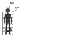
- FIG. 1 is a diagram showing an example of a group of original points. As shown in FIG. 1, a point group 102 of the object is included in the object space 101 and includes a plurality of points 103.
- the encoding device divides the original point group into an octree to a predetermined depth.
- octree division a target space is divided into eight nodes (subspaces), and 8-bit information (occupancy code) indicating whether a point group is included in each node is generated.
- the node including the point cloud is further divided into eight nodes, and 8-bit information indicating whether or not the point group is included in each of the eight nodes is generated. This process is repeated up to a predetermined hierarchy.
- 8-ary tree division is performed up to an intermediate layer, but is not performed on layers below that layer.
- Such an 8-ary tree up to an intermediate level is called a pruned 8-ary tree.
- FIG. 2 is a diagram showing an example of a pruned 8-ary tree. As shown in FIG. 2, the point cloud 102 is divided into a plurality of leaf nodes 104 (lowest layer nodes) of a pruned 8-ary tree.
- the encoding device performs the following processing on each leaf node 104 of the pruned 8-ary tree.
- leaf nodes are also simply referred to as nodes.
- the encoding device generates a vertex on the edge as a representative point of a point group close to the edge of the node. This vertex is called an edge vertex.
- edge vertex For example, edge vertices are generated for each of a plurality of edges (eg, four parallel sides).
- FIG. 3 is an example of a two-dimensional display of the leaf node 104, and is a diagram showing, for example, an xy plane viewed from the z direction shown in FIG. 1. As shown in FIG. 3, edge vertices 112 are generated on the edge based on points near the edge among the plurality of points 111 in the leaf node 104.
- the dotted line on the outer periphery of the leaf node 104 is an edge.
- the edge vertex 112 is generated at a position that is a weighted average of the positions of points within 1 distance from the edge (points included in the range 113 in FIG. 3).
- the unit of distance is, for example, the resolution of a point group, but is not limited thereto.
- this distance (threshold value) is 1 in this example, it may be other than 1 and may be variable.
- the encoding device also generates vertices inside the node based on the point group existing in the normal direction of the plane including the plurality of edge vertices. This vertex is called a centroid vertex.
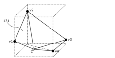
- FIGS. 4 and 5 are diagrams for explaining the method of generating centroid vertices.
- the encoding device selects, for example, four points as representative points from a group of edge vertices. In the example shown in FIG. 4, edge vertices v1 to v4 are selected.
- the encoding device calculates an approximate plane 121 passing through the four points.
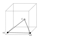
- the encoding device calculates the normal n of the approximate plane 121 and the average coordinate M of the four points.
- the encoding device converts the centroid vertex C into a weighted average coordinate of one or more points (for example, points included in the range 122 shown in FIG. 5) close to a half-line extending from the average coordinate M in the direction of the normal line n. generate.
- the encoding device entropy encodes vertex information, which is information on edge vertices and centroid vertices, and converts the encoded vertex information into a geometry data unit (hereinafter referred to as GDU) included in the bitstream. ).
- GDU geometry data unit
- the GDU includes information indicating a pruned 8-ary tree in addition to the vertex information.
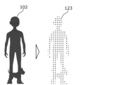
- FIG. 6 is a diagram showing an example of vertex information.
- the point group 102 is converted into vertex information 123, as shown in FIG.
- the decoding device decodes the GDU from the bitstream and obtains vertex information.
- the decoding device connects the vertices to generate a TriSoup-Surface, which is a group of triangles.
- FIG. 7 is a diagram showing an example of a trithorpe surface.
- four edge vertices v1 to v4 and a centroid vertex C are generated based on the vertex information.
- a triangle 131 (trisoap surface) having the centroid vertex C and two edge vertices as vertices is generated. For example, pairs of two edge vertices on two adjacent edges are each selected, and a triangle 131 having the selected pair and the centroid vertex as vertices is generated.
- FIG. 8 is a diagram for explaining the point cloud restoration process.
- the decoding device restores the position information of the point group 133 by generating points 132 at regular intervals on the surface of the triangle 131.
- FIG. 9 is a diagram showing an example where a point group extending in the vertical direction is divided into slices.
- FIG. 10 is a diagram showing an example of vertices generated in this case.
- the slice is divided from the bottom by nodes having a specified width.
- node 1 at the top of the slice includes a blank area.
- edge vertex v2 should be generated at the upper edge, but edge vertex v2 cannot be generated because there is no point group near the edge.
- the slice boundaries shown in FIGS. 9 and 10 are boundaries of bounding boxes of slices.
- FIG. 11 is a diagram showing an example of the trisoap surface that should originally be generated.
- FIG. 12 is a diagram showing an example of a trithorpe surface when no edge vertices are generated as shown in FIG. 10. As shown in FIG. 12, if edge vertices v2 and v3 are not generated on the upper edge, a trisoap surface is generated only with vertices v1 and v4 on the lower edge and the centroid vertex c. As a result, the trithorpe surface that should originally traverse the node is generated only at the bottom of the node.
- FIG. 13 is a diagram showing an example of the restored point group in this case. As shown in FIG. 13, since points are not restored in areas where there is no trisoap surface, holes are created across the restored point group, as in area 201 shown in FIG.
- the width of the node located at the edge of the bounding box of a slice is set to a width different from the specified width.
- FIG. 14 is a diagram showing an example of vertices generated in this case.
- FIG. 15 is a diagram showing an example of a trisoap surface in this case.
- a node 1 having an unspecified width is provided at the end of the slice.
- the blank space within the node 1 can be eliminated and the edge vertex v2 can be generated. Therefore, as shown in FIG. 15, it is possible to generate a tri-thorpe surface that traverses the inside of the node, thereby eliminating the generation of transverse holes in the restored point group.
- the encoding device stores, for example, information indicating the slice width in the GDU header as adjustment width information that is information for calculating the adjustment width of this non-standard width node.
- a non-specified width node is a node in which the length of a side along at least one of the length, width, and height is different from the specified length (specified width).
- the non-specified width node has a rectangular parallelepiped or cubic shape that is different from the cubic shape of the specified width.
- the adjustment width information is information for adjusting the specified length of the side of the node to an adjustment width of a side length different from the specified width (non-specified width).
- the adjustment width information may indicate the length of the adjustment width itself, may indicate the difference between the specified width and the adjustment width, or may indicate the ratio between the specified width and the adjustment width.
- the adjustment width (non-specified width) of a non-specified width node is expressed as min (slice width - node position, specified width).
- the non-specified width of a certain node is set to the minimum value between (slice width - node position) and the specified width.
- the node position is the position (coordinates) of the corner of the node that is closest to the origin, as shown in FIG.
- edge vertices can also be generated at the end nodes of the bounding box of the slice.
- the trisoap surface can be arranged without interruption, which eliminates the occurrence of holes in the restored point cloud.
- the point group included in the first slice is also included in the leaf node of the second slice.
- the first slice and the second slice have overlapping point groups.
- the point group is divided into slices by matching the boundary coordinates between the first slice and the second slice with the leaf node width. In other words, nodes with blank spaces due to slice division are not generated.
- Transmission information transmitted from the encoding device to the decoding device in order to implement the above method will be described below.
- transmission information is stored in a bitstream.
- FIG. 16 is a diagram showing an example of this transmission information.
- the GDU header included in the bitstream includes a non-standard width processing flag and slice width information.
- the non-standard width processing flag is information indicating whether or not to set the above-mentioned non-standard width node. For example, a value of 1 indicates that a non-standard width node is set, and a value of 0 indicates that a non-standard width node is not set.
- the slice width information indicates the slice width (the width of the bounding box of the slice).
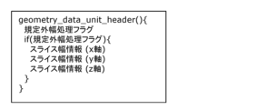
- FIG. 17 is a diagram showing an example of the syntax of the GDU header (geometry_data_unit_header). As shown in FIG. 17, slice width information is stored in the GDU header only when the non-standard width processing flag has a value of 1 (true). Further, the slice width information includes, for example, information indicating the width of each slice in the x, y, and z axes.
- the slice width information is information for each slice, and here, the non-standard width processing flag and slice width information are stored in the GDU header, which is a header for each slice.
- non-standard width processing flag may be information indicating whether slice width information is included in the bitstream.
- the names of flags, information, etc. shown in this embodiment are merely examples, and any names can be used.
- these pieces of information may be common to a plurality of slices.
- these pieces of information may be stored in a header higher than the GDU header, such as SPS or GPS.
- SPS Sequence Parameter Set
- GPS Global System Parameter Set
- GPS is metadata (parameter set) related to encoding of position information. For example, GPS is metadata common to multiple frames.
- a flag indicating whether this information is stored in the upper header or for each slice may be stored in the SPS or GPS. In this case, the storage location of these pieces of information is switched based on the flag.
- these pieces of information are for processing specific to the tri-soap method, they may be stored in the bitstream only when the encoding method is the tri-soap method.
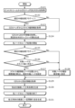
- FIG. 19 is a flowchart of encoding processing by the encoding device.
- the encoding device generates a pruned 8-ary tree, and stores 8-ary tree information indicating the pruned 8-ary tree in the GDU (S101). For example, the encoding device entropy encodes the octree information and stores the encoded octree information in the GDU.
- the encoding device performs the following steps S105 to S109 on each of the plurality of leaf nodes of the pruned octtree.
- the encoding device calculates the adjustment width from the slice width indicated by the slice width information and the node position of the target node, and adjusts the target node to the calculated adjustment width. (S107).
- the encoding device sets the width of the target node to the standard width ( S108).
- the encoding device generates edge vertices on the edges of the target node and generates centroid vertices inside the target node based on the point group distribution within the target node (S109). With the above, the loop processing for the target node is completed.
- the encoding device After the loop processing for all leaf nodes is completed, the encoding device entropy encodes the vertex information indicating the positions of the edge vertices and centroid vertices of the plurality of leaf nodes, and stores the encoded vertex information in the GDU. (S110).
- the encoding device generates a bitstream including the GDU header and GDU, and outputs the bitstream (S111). That is, the encoding device transmits the bitstream to the decoding device.
- FIG. 20 is a flowchart of the decoding process by the decoding device.
- the decoding device obtains the GDU header and GDU from the bitstream (S121).
- the decoding device obtains octree information from the GDU. For example, the decoding device acquires 8-ary tree information by entropy decoding the encoded 8-ary tree information included in the GDU. Next, the decoding device generates a group of leaf nodes of the pruned 8-ary tree using the 8-ary tree information (S124).
- the decoding device performs the following steps S125 to S130 on each of the plurality of leaf nodes of the pruned 8-ary tree.
- the decoding device calculates the adjustment width from the slice width indicated by the slice width information and the node position of the target node, and adjusts the target node to the calculated adjustment width. (S127).
- the decoding device sets the width of the target node to the specified width (S128). .
- the decoding device obtains vertex information indicating the positions of edge vertices and centroid vertices from the GDU (S129). For example, the decoding device acquires vertex information by entropy decoding encoded vertex information included in the GDU.
- the decoding device generates a triangle group by connecting a plurality of vertices indicated by the vertex information (S130). With the above, the loop processing for the target node is completed.
- the decoding device After completing the loop processing for all leaf nodes, the decoding device generates a decoded point group by generating points at regular intervals on the surfaces of multiple triangles (S131).
- FIGS. 21 to 24 are diagrams showing examples of setting non-standard width nodes.
- the position of the non-standard width node may be in the middle of the slice.
- the position of the non-standard width node may be at the beginning of the slice.
- a plurality of non-standard width nodes may be set.
- two non-standard width nodes may be set at both ends of the slice.
- two non-standard width nodes may be set at the end of the slice and at the middle of the slice.
- the sum of the widths of the plurality of non-standard width nodes only needs to be the above-mentioned adjustment width.
- non-standard width node information which is information for non-standard width nodes, that is stored in the bitstream.
- the non-specified width node information when the non-specified width node is placed at a location other than the end of the slice, the non-specified width node information includes the adjusted width information indicating the adjusted width and the insertion position of the non-specified width node. and insertion position information indicating the insertion position.
- the insertion position information indicates the bit string "4b0010”.
- the insertion position information indicates the bit string "4b1000”. Note that the plurality of bits in the bit string each correspond to a node, and the bit corresponding to the non-standard width node is set to 1, and the other bits are set to 0.
- the insertion position information may indicate information that specifies a non-standard width node.
- a serial number identifier
- the insertion position information may indicate a serial number of a non-standard width node.
- a serial number may be set for each axis within a slice. In this case, in the example shown in FIG. 21, serial numbers 1, 2, 3, and 4 are set in order from the left node, and the insertion position information indicates the value 3.
- the serial number may be a serial number for all nodes within a slice.
- the decoding device can use the insertion position information to determine whether the target node is a non-standard width node. Further, the adjustment width can be calculated using the same method as shown in FIG.
- the insertion position information indicates the individual insertion positions of the multiple non-standard width nodes.
- the insertion position information indicates the bit string "5b1001".
- the insertion position information indicates the bit string "5b10010". Note that here we have shown an example in which one bit string is used for one axis (x-axis in this example) (that is, an example in which a different bit string is used for each axis), but one bit string is used for all nodes in the slice. Two bit strings may be used.
- the adjustment width information indicates the adjustment width of each of the two non-standard width nodes. Specifically, the adjustment width information indicates a value 2, which is the adjustment width of the first non-standard width node, and a value 2, which is the adjustment width of the second non-standard width node.
- the adjustment width information may indicate the total adjustment width of two non-standard width nodes and the adjustment width of one non-standard width node.
- the decoding device can calculate the adjustment widths of the two non-standard width nodes from the adjustment width information.
- the adjustment width information of the last non-standard width node in a row of non-standard width nodes on one axis is omitted, a rule is determined in advance, and the decoding device , the adjustment widths of the two non-standard width nodes may be calculated from the adjustment width information.
- the non-standard width node information may be composed of individual information of all non-standard width nodes within a slice, instead of information for each axis.
- FIG. 25 is a diagram showing an example of setting the non-standard width node in this case.
- the example shown in FIG. 25 is an example in which the node at the end of the slice is set to a non-standard width node.
- the non-standard width node information includes the amount of offset from the origin coordinates to the start position of the bounding box of the slice.
- the decoding device can calculate the adjustment width using this offset amount.
- the non-standard width node information includes information indicating the fractional node width, which is the adjusted width of the node at the end of the slice. The decoding device uses this information to set the adjustment width of the node at the edge of the slice to the fractional node width.
- FIG. 26 is a diagram showing an example of setting the non-standard width node in this case.
- the non-specified width may be a value larger than the specified width.
- the third node and the fourth node may be combined. That is, three nodes whose widths are 32, 32, and 36 from the left may be set.
- the node may become a cube.
- the position information of the corner of the node may be transmitted so that the size of the non-standard width node can be restored.
- the position information may be coordinate information of two corners in the direction of the non-standard width, or may be coordinate information of all eight corners.
- the encoding device may quantize the above-mentioned non-standard width node information for calculating the adjustment width, and transmit the quantized information to the decoding device.
- the decoding device may perform the above processing by dequantizing the quantized information and using the obtained non-standard width node information. In this case, a case may occur in which the width of the blank area within the non-standard width node does not become completely zero. On the other hand, by performing quantization, the amount of data to be transmitted can be reduced.
- the default size of the node is determined depending on the size of the bounding box to be octree encoded (bit depth of the original data) and the depth to which the octree division is to proceed. be done.
- This specified width is expressed, for example, as a power of two.
- a non-standard width node is a node in which the length of a side along at least one of the length, width, and height differs from the specified width, but the length in only one direction, or in only two directions.
- the length may be different from the specified width. That is, the non-standard width node may be a rectangular parallelepiped.
- edge vertices existing on four parallel edges of a node are found, but the number of edge vertices to be found is not limited to four.
- the number of edge vertices is not particularly limited as long as an approximate plane is obtained.
- the method of finding the centroid apex is not limited to the above method. As long as the decoding device can determine the plane of the triangle, the centroid vertices may be determined using other methods.
- the tri-soap method was used as the compression method, but the method of this embodiment is also effective for compression methods other than the tri-soap method.
- the method of this embodiment is a compression method that approximates a point group using a plane or curved surface within a node, and is effective for a compression method that requires edge vertices to generate the plane or curved surface. It is.
- the non-standard length of the side of the non-standard width node is determined, but it is not essential to determine the non-standard length. It is only necessary to find the shape of the non-standard width node; for example, the positions of the two ends of the side with the non-standard length may be found. That is, the position of the non-standard width node may be determined.
- the origin of the slice is an unspecified offset amount, and the starting position of the bounding box of the slice does not necessarily match the origin. Therefore, there may be a case where the point group of the slice after subtracting this offset amount is distributed away from the origin of the encoding coordinate system. That is, there are cases where the origin of the encoded coordinate system and the origin of the bounding box of the slice are different. Furthermore, in this case, the boundaries of the bounding box of the slice may not coincide with the boundaries of the leaf nodes. In this case, it is necessary to generate non-standard width nodes on both the side of the bounding box of the slice on the origin side and the side of the bounding box on the side far from the origin.
- the encoding device uses the slice position, which is the start coordinate of the bounding box of the slice, and the width of the bounding box as information for the decoding device to calculate the node position and node width (adjusted width) of these non-standard width nodes.
- the slice width is transmitted to the decoding device.
- FIG. 27 is a diagram showing an example of setting the non-standard width node in this case.
- the encoded coordinate system is expressed one-dimensionally.
- the shaded area is an area (slice) in which the point group is distributed.
- the origin shown in FIG. 27 is the origin of the encoding coordinate system.
- the adjusted node position newNodePos and the adjusted node width newNodeWidth are calculated as follows. .
- the node position is adjusted to A if nodePos ⁇ A, otherwise it is not adjusted. That is, the node position of node 1, which is the leading node, is changed from P1 to A, and the node positions of the other nodes are not changed.
- the node widths of other nodes are set to W.
- the decoding device obtains A and B from the transmission information, and uses the above formula from the initial node position and initial node width of each node. are used to calculate the adjusted node positions and adjusted node widths of nodes 1 and 2.
- the position of the non-standard width node may be located at the beginning of the slice, in the middle of the slice, at both ends of the slice, or at multiple positions.
- the total node width may be the above-mentioned adjustment width.
- the following can be used as the calculation method and the non-standard width node information, which is information for non-standard width nodes, that is stored in the bitstream.
- FIG. 29 is a diagram showing an example of setting a non-standard width node.
- the encoding device can calculate the adjusted position and adjustment width of node 1 on the origin side.
- the decoding device can calculate the adjustment width of the node 2 on the far side from the origin.
- the non-standard width node information also includes information specifying a non-standard width node and the information for the specified node.
- Information indicating the adjustment position and adjustment width of the node may be included.
- the information specifying the non-standard width node indicates, for example, a serial number assigned to the node.
- FIG. 30 is a diagram showing an example of setting the non-standard width node in this case.
- 0 to 3 are assigned as node numbers, which are serial numbers of nodes.
- FIG. 29 a method for determining a non-standard width node and calculating its position and width has been explained, but it is also possible to use any of the methods explained in FIGS. Good too.
- FIG. 31 is a diagram illustrating an example of the syntax of GPS (geometry_parameter_set) and GDU header.
- the GPS includes a first non-standard width processing flag and a second non-standard width processing flag.
- the first non-standard width processing flag is information indicating whether or not to perform the above-described node position and node width adjustment on the node located at the end of the slice closer to the origin. For example, a value of 1 indicates that the adjustment is performed, and a value of 0 indicates that the adjustment is not performed.
- the second non-standard width processing flag is information indicating whether or not to perform the above-described node width adjustment on the node located at the slice end on the side far from the origin. For example, a value of 1 indicates that the adjustment is performed, and a value of 0 indicates that the adjustment is not performed.
- the GDU header includes first bit length information, a first quantization parameter, and slice position information.
- the slice position information indicates the slice position, which is the position (coordinates) of the bounding box of the slice, and for example, indicates the three-dimensional coordinates (x, y, z coordinates) of the corner of the bounding box of the slice that is closest to the origin. .
- the first bit length information indicates the bit length of slice position information.
- the first quantization parameter indicates a quantization parameter (quantization value) used for quantizing slice position information.
- the GDU header includes second bit length information, a second quantization parameter, and slice width information.
- the slice width information indicates the slice width, which is the width of the bounding box of the slice.
- the slice width information indicates the width of the bounding box in each of the x, y, and z directions.
- the second bit length information indicates the bit length of the slice width.
- the second quantization parameter indicates a quantization parameter used for quantizing slice width information.
- the slice position is represented by slice position information ⁇ first quantization parameter
- the slice width is represented by slice width information ⁇ second quantization parameter.
- these pieces of information are stored for each slice, but if these pieces of information are common to multiple slices, these pieces of information are stored above the GDU header such as SPS or GPS. may be stored in the header of Further, a flag indicating whether this information is stored in the upper header or for each slice may be stored in the SPS or GPS. In this case, the storage location of these pieces of information is switched based on the flag. Furthermore, this information may be provided individually for each axis of x, y, and z.
- the encoding device does not need to transmit the first non-standard width processing flag and the second non-standard width processing flag shown in FIG. 31.
- the slice position information and the slice width information are numerical values in the encoded coordinate system, they may be determined to be positive values.
- the encoding device performs this omission determination and transmits information indicating the determination result to the decoding device.
- a dedicated flag may be used for this transmission, or the first bit length information and second bit length information described above may be used. Specifically, when the first bit length information indicates 0, it means that transmission of slice position information is omitted, and when the second bit length information indicates 0, it means that transmission of slice width information is omitted. means. This allows the amount of header data to be suppressed and the processing time for encoding processing to be shortened.
- FIG. 32 is a diagram showing an example of a slice and a node when the starting end of the slice coincides with the origin. In this case, there is no need to adjust the starting end.
- FIG. 33 is a diagram showing an example of a slice and a node in a case where the start end of the slice coincides with the origin and the end end of the slice coincides with the end end of the node. In this case, adjustment processing is not required for both the start end and the end end.
- FIG. 34 is a diagram showing an example of processing (syntax) when the above omission is performed.
- slice_bb_pos_bits shown in the figure is first bit length information indicating the bit length of slice position information.
- slice_bb_width_bits is second bit length information indicating the bit length of slice width information.
- A is the slice position
- B is the slice width
- nodePos is the node position (node position before adjustment)
- nodeWidth is the node width (node width before adjustment)
- newNodeWidth is the node after adjustment.
- W is the specified width of the node.
- the adjustment process is performed only when the bit length of the slice position information is a value greater than 0, so the processing time of the encoding process can be reduced. Furthermore, if the start end of a slice coincides with the origin or the end end coincidentally coincides with the end end of a node, the amount of data in the header can be reduced.
- FIG. 35 is a diagram showing an example of the syntax of the GPS and GDU headers in this case.
- the syntax shown in FIG. 35 differs from the syntax shown in FIG. 31 in that the first quantization parameter and slice position information are stored in the GDU header only when the first bit length information is greater than 0. and a condition that the second quantization parameter and slice width information are stored in the GDU header only when the second bit length information is greater than 0 are added.
- the amount of data in the header can be reduced when the start end of the slice matches the origin or the end end matches the end end of the node.
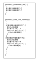
- FIG. 36 is a flowchart of the omission determination process of the start end adjustment process (slice position transmission).
- the encoding device determines whether the start position of the slice (coordinates of the start end of the bounding box of the slice) matches the origin (S201).
- the encoding device transmits slice position information (S203). That is, the encoding device stores slice_bb_pos_bits set to a value greater than 0 and slice position information in the bitstream.
- FIG. 37 is a flowchart of the omission determination process of the end end adjustment process (slice width transmission).
- the encoding device determines whether the end position of the slice (coordinates of the end of the bounding box of the slice) matches the end of the node (S211).
- the encoding device transmits slice width information (S213). That is, the encoding device stores slice_bb_width_bits set to a value greater than 0 and slice width information in the bitstream.
- FIG. 38 is a flowchart of the node position determination process. For example, the process shown in FIG. 38 is performed for each node.
- the encoding device determines whether the first bit length information (slice_bb_pos_bits) is greater than 0 (S221).
- the encoding device determines whether the node position (nodePos) of the target node is smaller than the slice position (S222).
- the encoding device sets the slice position as the adjusted node position (S223).
- the encoding device does not change (adjust) the node position (S224).
- FIG. 39 is a flowchart of the node width determination process. For example, the process shown in FIG. 39 is performed for each node.
- the encoding device determines whether the first bit length information (slice_bb_pos_bits) is greater than 0 (S231).
- the encoding device determines whether the node position (nodePos) of the target node is smaller than the slice position (S232).
- the encoding device sets the specified width (W) - (slice position (A) - node position (nodePos)) as the adjusted node width (nodeWidth). (S233).
- the encoding device determines whether the second bit length information (slice_bb_width_bits) is greater than 0 (S234).
- the encoding device converts min(slice position (A) + slice width (B) - node position (nodePos) + 1, specified width (W)) into a node. It is set as the width (nodeWidth) (S235).
- the encoding device does not change the node width (nodeWidth) (S236). That is, the encoding device sets the node width to the specified width (W).
- the encoding device determines whether the second bit length information (slice_bb_width_bits) is greater than 0 (S237). Note that the case where the first bit length information is 0 (No in S231) means that the slice position information is not transmitted, and the start end of the slice coincides with the origin.
- the encoding device sets min(slice width (B) - node position (nodePos) + 1, specified width (W)) as the node width (nodeWidth). (S238).
- the encoding device does not change the node width (nodeWidth) (S236). That is, the encoding device sets the node width to the specified width (W).
- the decoding device (three-dimensional data decoding device) according to the embodiment performs the processing shown in FIG. 40.
- the decoding device is a decoding device that decodes a plurality of three-dimensional points.
- the decoding device obtains a plurality of nodes having an octree structure and included in the first slice from the bitstream (S301), and derives the shape of the first node among the plurality of nodes from the bitstream. (S302), the first node is decoded according to the information (S303), and the shape of the first node is different from the prescribed shape of other nodes among the plurality of nodes. According to this, it is possible to set a node having a shape different from the prescribed shape. Therefore, variable nodes can be set according to the size of the slice or the distribution of the point group. Therefore, there is a possibility that encoding efficiency can be improved.
- the shape of the first node is a rectangular parallelepiped, not a cube.
- the edge of the first slice coincides with the edge of any one of the plurality of nodes. According to this, even if the node end and the slice end do not match, the node end and the slice end can be made to match. Therefore, since it is possible to prevent a vertex from being generated at the end of the node, it is possible to suppress the generation of blank areas at slice boundaries. Therefore, the accuracy of the point cloud to be decoded can be improved.
- the size of the shape of the first node is different from the prescribed size of the prescribed shape.
- the length of the side of the shape of the first node is different from the prescribed length (eg, prescribed width) of the side of the prescribed shape.
- the information for deriving the shape of the first node indicates the size of the shape of the first node or the positions of both ends of the sides of the first node. According to this, the decoding device can generate a node having a shape different from the prescribed shape using the information.
- the information for deriving the shape of the first node includes adjustment information (for example, slice width information or slice position information) for adjusting the prescribed shape to the shape of the first node.
- the decoding device can generate a node having a shape different from the prescribed shape using the adjustment information. Furthermore, compared to the case where the absolute amount of position information is sent, there is a possibility that the amount of information can be made smaller.
- the decoding of the first node is performed according to a compression method in which a plurality of three-dimensional points are approximated by a plane or curved surface within the first node.
- the compression method is the Triangle-Soup compression method.
- the shape of the first node is determined in order to generate a plane or a curved surface within the first node. According to this, by setting a node having a shape different from the prescribed shape, a plane or a curved surface can be generated within the first node.
- the edge of the shape of the first node has a vertex on it, and the plane or curved surface intersects the edge at the vertex.
- a plane or a curved surface can be generated within the first node.
- the plurality of three-dimensional points include a first three-dimensional point located near the vertex.
- the first node is provided in contact with a second slice adjacent to the first slice.
- a node end and a slice end do not match, it is possible to prevent a vertex from being generated at the node end, so it is possible to suppress the generation of blank areas at slice boundaries.
- the slice boundary may separate the nodes. In that case, the first node cannot be encoded or decoded using the point cloud in the second slice adjacent to the first slice, so the accuracy of restoring the three-dimensional point cloud near the slice boundary may deteriorate. There is.
- the end of the first node can be made to coincide with the end of the first slice, for example.
- the end of the first node can be made to coincide with the end of the first slice, for example.
- information for deriving the shape of the first node is provided for each slice, and information for the second slice has an 8-ary tree structure, and information for deriving the shape of the first node is provided for each slice. is used to derive the shape of the second node, and the shape of the second node is different from the prescribed shape. According to this, the shape of the node can be set for each slice.
- the size of the prescribed shape is expressed as a power of two
- the size of the first node shape is different from the size expressed as a power of two.
- the shape of the first node is defined by a first length along a first direction, a second length along a second direction, and a third length along a third direction;
- the first direction, second direction, and third direction are orthogonal to each other, and only the first length among the first length, second length, and third length defines a node other than the first node.
- the length is different from the length of the shape, or only the first length and the second length among the first length, the second length and the third length are different from the length of the prescribed shape.
- the first node is closest to the origin of the first slice among the plurality of nodes in one of the first direction, the second direction, and the third direction;
- the third directions are orthogonal to each other. According to this, when the start position of the slice does not match the origin, for example, the start position of the node can be adjusted in accordance with the start position of the slice.
- the origin is a position of a slice, a node, a three-dimensional point, or a reference position for defining a shape.
- the plurality of nodes include a third node having a shape different from the prescribed shape, and the third node is the farthest from the origin in one direction among the plurality of nodes. According to this, when the end position of a slice does not match the end position of a node, for example, the end position of a node can be adjusted in accordance with the end position of a slice.
- the bitstream contains information for deriving the shape of the first node
- the bitstream contains the information for deriving the shape of the first node. It does not contain information for deriving the shape of the node. According to this, the occurrence of processing for adjusting the shape of the node can be reduced. Furthermore, transmission of information for deriving the shape of the node can be omitted. Therefore, it is possible to reduce the amount of processing and the amount of bitstream data.
- start position (starting end) of a slice is the position of the end of the slice closer to the origin
- end position (end end) of the slice is the position of the end of the slice farther from the origin.
- starting position (starting edge) of a node is the position of the edge of the node on the side closer to the origin
- ending position (end edge) of a node is the position of the edge of the node on the side far from the origin.
- the bitstream includes information for deriving the shape of the first node, and the ending position of the first slice does not match the ending edge of the first node.
- the bitstream does not contain information for deriving the shape of the first node. According to this, the occurrence of processing for adjusting the shape of the node can be reduced. Furthermore, transmission of information for deriving the shape of the node can be omitted. Therefore, it is possible to reduce the amount of processing and the amount of bitstream data.
- FIG. 41 is a block diagram of the decoding device 10.
- the decoding device 10 includes a processor 11 and a memory 12, and the processor 11 uses the memory 12 to perform the above processing.
- the encoding device (three-dimensional data encoding device) according to the embodiment performs the processing shown in FIG. 42.
- the encoding device is an encoding device that encodes a plurality of three-dimensional points.
- the encoding device has an octree structure, generates a bitstream by encoding multiple nodes included in the first slice (S311), and derives the shape of the first node among the multiple nodes.
- information for the first node is stored in the bitstream (S312), and the shape of the first node is different from the prescribed shape of other nodes among the plurality of nodes.
- the encoding device may perform the same processing as the decoding device described above.
- FIG. 43 is a block diagram of the encoding device 20.
- the encoding device 20 includes a processor 21 and a memory 22, and the processor 21 uses the memory 22 to perform the above processing.
- the present disclosure is limited to this embodiment. It is not something that will be done.
- each processing unit included in the encoding device, decoding device, etc. is typically realized as an LSI, which is an integrated circuit. These may be integrated into one chip individually, or may be integrated into one chip including some or all of them.
- circuit integration is not limited to LSI, and may be realized using a dedicated circuit or a general-purpose processor.
- An FPGA Field Programmable Gate Array
- a reconfigurable processor that can reconfigure the connections and settings of circuit cells inside the LSI may be used.
- each component may be configured with dedicated hardware, or may be realized by executing a software program suitable for each component.
- Each component may be realized by a program execution unit such as a CPU or a processor reading and executing a software program recorded on a recording medium such as a hard disk or a semiconductor memory.
- the present disclosure also describes an encoding method (three-dimensional data encoding method) or a decoding method (three-dimensional data decoding method), etc.
- the present disclosure may be implemented as a program that executes the encoding method or decoding method on a computer, processor, or device. Further, the present disclosure may be implemented as a bitstream generated by the above encoding method. Further, the present disclosure may be realized as a recording medium on which the program or the bitstream is recorded. For example, the present disclosure may be realized as a non-transitory computer-readable recording medium on which the program or the bitstream is recorded.
- the present disclosure can be applied to encoding devices and decoding devices.
Landscapes
- Engineering & Computer Science (AREA)
- Multimedia (AREA)
- Physics & Mathematics (AREA)
- General Physics & Mathematics (AREA)
- Theoretical Computer Science (AREA)
- Compression Or Coding Systems Of Tv Signals (AREA)
Abstract
Provided is a decoding method for decoding a plurality of three-dimensional points, the decoding method comprising: acquiring, from a bit stream, a plurality of nodes having an octree structure and included in a first slice (S301); acquiring, from the bit stream, information for deriving the shape of a first node among the plurality of nodes (S302); and decoding the first node according to the information (S303). The shape of the first node is different from the prescribed shape of the other nodes among the plurality of nodes. For example, the shape is a rectangular parallelepiped shape, and need not be a cube shape.
Description
本開示は、復号方法、符号化方法、復号装置及び符号化装置に関する。
The present disclosure relates to a decoding method, an encoding method, a decoding device, and an encoding device.
自動車或いはロボットが自律的に動作するためのコンピュータビジョン、マップ情報、監視、インフラ点検、又は、映像配信など、幅広い分野において、今後、三次元データを活用した装置又はサービスの普及が見込まれる。三次元データは、レンジファインダなどの距離センサ、ステレオカメラ、又は複数の単眼カメラの組み合わせなど様々な方法で取得される。
In the future, devices and services that utilize three-dimensional data are expected to become more widespread in a wide range of fields, including computer vision for autonomous operation of cars or robots, map information, monitoring, infrastructure inspection, and video distribution. Three-dimensional data is acquired by various methods, such as a distance sensor such as a range finder, a stereo camera, or a combination of multiple monocular cameras.
三次元データの表現方法の1つとして、三次元空間内の点群によって三次元構造の形状を表すポイントクラウドと呼ばれる表現方法がある。ポイントクラウドでは、点群の位置と色とが格納される。ポイントクラウドは三次元データの表現方法として主流になると予想されるが、点群はデータ量が非常に大きい。よって、三次元データの蓄積又は伝送においては二次元の動画像(一例として、MPEGで規格化されたMPEG-4 AVC又はHEVCなどがある)と同様に、符号化によるデータ量の圧縮が必須となる。
One of the methods for expressing three-dimensional data is a method called point cloud, which represents the shape of a three-dimensional structure using a group of points in three-dimensional space. A point cloud stores the positions and colors of point clouds. Point clouds are expected to become the mainstream method for expressing three-dimensional data, but point clouds require a very large amount of data. Therefore, when storing or transmitting three-dimensional data, it is essential to compress the amount of data through encoding, just as with two-dimensional moving images (an example is MPEG-4 AVC or HEVC standardized by MPEG). Become.
また、ポイントクラウドの圧縮については、ポイントクラウド関連の処理を行う公開のライブラリ(Point Cloud Library)などによって一部サポートされている。
Additionally, point cloud compression is partially supported by a public library (Point Cloud Library) that performs point cloud-related processing.
また、三次元の地図データを用いて、車両周辺に位置する施設を検索し、表示する技術が知られている(例えば、特許文献1参照)。
Additionally, there is a known technology that uses three-dimensional map data to search for and display facilities located around a vehicle (for example, see Patent Document 1).
このような符号化方法及び復号方法では、符号化効率の向上が望まれている。
In such encoding and decoding methods, it is desired to improve the encoding efficiency.
本開示は、符号化効率を向上できる復号方法、符号化方法、復号装置又は符号化装置を提供することを目的とする。
An object of the present disclosure is to provide a decoding method, an encoding method, a decoding device, or an encoding device that can improve encoding efficiency.
本開示の一態様に係る復号方法は、複数の三次元点を復号する復号方法であって、ビットストリームから、8分木構造を有し、第1スライスに含まれる複数のノードを取得し、前記ビットストリームから、前記複数のノードのうちの第1ノードの形状を導出するための情報を取得し、前記第1ノードを前記情報に従い復号し、前記形状は、前記複数のノードのうちの他のノードの規定形状と異なる。
A decoding method according to an aspect of the present disclosure is a decoding method for decoding a plurality of three-dimensional points, and the method includes acquiring a plurality of nodes having an octree structure and included in a first slice from a bitstream; Information for deriving the shape of a first node among the plurality of nodes is obtained from the bitstream, the first node is decoded according to the information, and the shape is different from other nodes among the plurality of nodes. differs from the prescribed shape of the node.
本開示の一態様に係る符号化方法は、複数の三次元点を符号化する符号化方法であって、8分木構造を有し、第1スライスに含まれる複数のノードを符号化することでビットストリームを生成し、前記複数のノードのうちの第1ノードの形状を導出するための情報を前記ビットストリームに格納し、前記形状は、前記複数のノードのうちの他のノードの規定形状と異なる。
An encoding method according to an aspect of the present disclosure is an encoding method that encodes a plurality of three-dimensional points, has an octree structure, and encodes a plurality of nodes included in a first slice. generates a bitstream, and stores information for deriving a shape of a first node among the plurality of nodes in the bitstream, and the shape is a prescribed shape of another node among the plurality of nodes. different from.
本開示は、符号化効率を向上できる復号方法、符号化方法、復号装置又は符号化装置を提供できる。
The present disclosure can provide a decoding method, an encoding method, a decoding device, or an encoding device that can improve encoding efficiency.
本開示の一態様に係る三次元データ復号方法は、複数の三次元点を復号する復号方法であって、ビットストリームから、8分木構造を有し、第1スライスに含まれる複数のノードを取得し、前記ビットストリームから、前記複数のノードのうちの第1ノードの形状を導出するための情報を取得し、前記第1ノードを前記情報に従い復号し、前記形状は、前記複数のノードのうちの他のノードの規定形状と異なる。これによれば、規定形状とは異なる形状のノードを設定できる。よって、スライスの大きさ又は点群の分布状況に合わせて可変のノードを設定できる。よって、符号化効率を向上できる可能性がある。
A three-dimensional data decoding method according to an aspect of the present disclosure is a decoding method for decoding a plurality of three-dimensional points, and the method decodes a plurality of nodes having an octree structure and included in a first slice from a bitstream. obtain information for deriving the shape of a first node among the plurality of nodes from the bitstream, decode the first node according to the information, and determine the shape of the plurality of nodes. It is different from the prescribed shape of my other nodes. According to this, it is possible to set a node having a shape different from the prescribed shape. Therefore, variable nodes can be set according to the size of the slice or the distribution of the point group. Therefore, there is a possibility that encoding efficiency can be improved.
例えば、前記形状は直方体形状であり、立方体形状ではなくてもよい。例えば、前記第1スライスの端は、前記複数のノードのうちのいずれかのノードの端と一致していてもよい。これによれば、ノード端とスライス端とが一致しない場合に、ノード端とスライス端とを一致させることができる。よって、当該ノード端に頂点が生成されないことを抑制できるので、スライス境界における空白領域の発生を抑制できる。よって、復号される点群の精度を向上できる。
For example, the shape may be a rectangular parallelepiped, and may not be a cube. For example, an edge of the first slice may coincide with an edge of any one of the plurality of nodes. According to this, even if the node end and the slice end do not match, the node end and the slice end can be made to match. Therefore, since it is possible to prevent a vertex from being generated at the end of the node, it is possible to suppress the generation of blank areas at slice boundaries. Therefore, the accuracy of the point cloud to be decoded can be improved.
例えば、前記情報は、前記形状のサイズ、又は、前記第1ノードの辺の両端の位置、を示してもよい。これによれば、復号装置は、当該情報を用いて規定形状と異なる形状のノードを生成できる。
For example, the information may indicate the size of the shape or the positions of both ends of the side of the first node. According to this, the decoding device can generate a node having a shape different from the prescribed shape using the information.
例えば、前記情報は、前記規定形状を前記形状に調整するための調整情報を含んでもよい。これによれば、復号装置は、調整情報を用いて規定形状と異なる形状のノードを生成できる。また、位置の情報の絶対量を送る場合に比べて、情報量を小さくできる可能性がある。
For example, the information may include adjustment information for adjusting the prescribed shape to the shape. According to this, the decoding device can generate a node having a shape different from the prescribed shape using the adjustment information. Furthermore, compared to the case where the absolute amount of position information is sent, there is a possibility that the amount of information can be made smaller.
例えば、前記復号は、前記複数の三次元点が前記第1ノード内の平面又は曲面で近似される圧縮方式に従い実行されてもよい。例えば、前記圧縮方式は、Triangle-Soup圧縮方式であってもよい。
For example, the decoding may be performed according to a compression method in which the plurality of three-dimensional points are approximated by a plane or a curved surface within the first node. For example, the compression method may be a Triangle-Soup compression method.
例えば、前記平面又は前記曲面を前記第1ノード内に生成するために前記形状が決定されてもよい。これによれば、規定形状とは異なる形状のノードを設定することで、平面又は曲面を第1ノード内に生成できる。
For example, the shape may be determined to generate the plane or the curved surface within the first node. According to this, by setting a node having a shape different from the prescribed shape, a plane or a curved surface can be generated within the first node.
例えば、前記形状の辺はその上に頂点を持ち、前記平面または前記曲面は、前記頂点で前記辺と交差してもよい。これによれば、規定形状とは異なる形状のノードを設定することで、平面又は曲面を第1ノード内に生成できる。
For example, the side of the shape may have an apex thereon, and the plane or curved surface may intersect the side at the apex. According to this, by setting a node having a shape different from the prescribed shape, a plane or a curved surface can be generated within the first node.
例えば、前記第1ノードは、前記第1スライスに隣接する第2スライスと接して設けられてもよい。これによれば、例えば、ノード端とスライス端とが一致しない場合に、当該ノード端に頂点が生成されないことを抑制できるので、スライス境界における空白領域の発生を抑制できる。例えば、スライス境界で規定形状のノードしか設けない場合、スライス境界がノードを区切る場合がある。その場合、第1スライスに隣接する第2スライス内の点群を使って第1ノードの符号化又は復号を行うことができないので、スライス境界付近における三次元点群の復元精度が悪化する可能性がある。そこで、この態様では、規定形状とは異なる形状のノードを設定することで、例えば、第1ノードの端を第1スライスの端と一致させることができる。これにより、スライス境界付近における三次元点群の復元精度の悪化を抑制できる。なお、この態様をトライソープ方式に適用すれば、エッジ頂点が適切に生成されないことを抑制できる。
For example, the first node may be provided in contact with a second slice adjacent to the first slice. According to this, for example, when a node end and a slice end do not match, it is possible to prevent a vertex from being generated at the node end, so it is possible to suppress the generation of blank areas at slice boundaries. For example, if only nodes of a prescribed shape are provided at the slice boundary, the slice boundary may separate the nodes. In that case, the first node cannot be encoded or decoded using the point cloud in the second slice adjacent to the first slice, so the reconstruction accuracy of the three-dimensional point cloud near the slice boundary may deteriorate. There is. Therefore, in this aspect, by setting a node having a shape different from the prescribed shape, the end of the first node can be made to coincide with the end of the first slice, for example. Thereby, it is possible to suppress deterioration in the reconstruction accuracy of the three-dimensional point group near the slice boundary. Note that if this aspect is applied to the tri-soap method, it is possible to prevent edge vertices from being generated appropriately.
例えば、前記情報はスライスごとに設けられ、前記第2スライスの前記情報は、8分木構造を有し、前記第2スライスに含まれる複数のノードのうちの第2ノードの形状を導出するために使用され、前記第2ノードの形状は前記規定形状と異なってもよい。これによれば、スライス毎にノードの形状を設定できる。
For example, the information is provided for each slice, and the information of the second slice has an 8-ary tree structure, and is used to derive the shape of the second node among the plurality of nodes included in the second slice. and the shape of the second node may be different from the prescribed shape. According to this, the shape of the node can be set for each slice.
例えば、前記規定形状のサイズは2のべき乗で表され、前記形状のサイズは2のべき乗で表されるサイズとは異なってもよい。
For example, the size of the prescribed shape may be expressed as a power of two, and the size of the shape may be different from the size expressed as a power of two.
例えば、前記第1ノードの前記形状は、第1方向に沿った第1の長さ、第2方向に沿った第2の長さ、および第3方向に沿った第3の長さによって定義され、前記第1方向、前記第2方向、および前記第3方向は互いに直交し、前記第1の長さ、前記第2の長さ及び前記第3の長さのうち前記第1の長さだけが前記第1ノード以外のノードの前記規定形状の長さと異なる、又は、前記第1の長さ、前記第2の長さ及び前記第3の長さのうち前記第1の長さ及び前記第2の長さだけが、それぞれ前記規定形状の長さと異なってもよい。
For example, the shape of the first node is defined by a first length along a first direction, a second length along a second direction, and a third length along a third direction. , the first direction, the second direction, and the third direction are orthogonal to each other, and only the first length is the first length, the second length, and the third length. is different from the length of the prescribed shape of a node other than the first node, or the first length and the third length are different from the length of the prescribed shape of the nodes other than the first node, or 2 may differ from the length of the defined shape, respectively.
例えば、前記第1ノードは、第1方向、第2方向及び第3方向のうちの一つの方向において、前記複数のノードのうちで前記第1スライスの原点に最も近く、前記第1方向、前記第2方向、および前記第3方向は互いに直交してもよい。これによれば、スライスの開始位置が原点と一致しない場合において、例えば、スライスの開始位置に合わせてノードの開始位置を調整できる。
For example, the first node is closest to the origin of the first slice among the plurality of nodes in one of a first direction, a second direction, and a third direction; The second direction and the third direction may be orthogonal to each other. According to this, when the start position of the slice does not match the origin, for example, the start position of the node can be adjusted in accordance with the start position of the slice.
例えば、前記複数のノードは、前記規定形状とは異なる形状を持つ第3ノードを含み、前記第3ノードは、前記複数のノードのうち、前記一つの方向において前記原点から最も遠くてもよい。これによれば、スライスの終了位置がノードの終了位置と一致しない場合において、例えば、スライスの終了位置に合わせてノードの終了位置を調整できる。
For example, the plurality of nodes may include a third node having a shape different from the prescribed shape, and the third node may be farthest from the origin in the one direction among the plurality of nodes. According to this, when the end position of a slice does not match the end position of a node, for example, the end position of a node can be adjusted in accordance with the end position of a slice.
例えば、前記第1スライスの開始位置が原点と一致しない場合、前記ビットストリームは前記情報を含み、前記第1スライスの開始位置が原点と一致する場合、前記ビットストリームは前記情報を含まなくてもよい。これによれば、ノードの形状を調整するための処理の発生を低減できる。また、ノードの形状を導出するための情報の伝送を省略できる。よって、処理量の低減及びビットストリームのデータ量の低減を実現できる。
For example, if the starting position of the first slice does not coincide with the origin, the bitstream may include the information, and if the starting position of the first slice coincides with the origin, the bitstream may not include the information. good. According to this, the occurrence of processing for adjusting the shape of the node can be reduced. Furthermore, transmission of information for deriving the shape of the node can be omitted. Therefore, it is possible to reduce the amount of processing and the amount of bitstream data.
例えば、前記第1スライスの終了位置が前記第1ノードの終了端と一致しない場合、前記ビットストリームは、前記情報を含み、前記第1スライスの終了位置が前記第1ノードの終了端と一致する場合、前記ビットストリームは前記情報を含まなくてもよい。これによれば、ノードの形状を調整するための処理の発生を低減できる。また、ノードの形状を導出するための情報の伝送を省略できる。よって、処理量の低減及びビットストリームのデータ量の低減を実現できる。
For example, if the end position of the first slice does not match the end of the first node, the bitstream includes the information, and the end position of the first slice does not match the end of the first node. In this case, the bitstream may not include the information. According to this, the occurrence of processing for adjusting the shape of the node can be reduced. Furthermore, transmission of information for deriving the shape of the node can be omitted. Therefore, it is possible to reduce the amount of processing and the amount of bitstream data.
本開示の一態様に係る三次元データ符号化方法は、複数の三次元点を符号化する符号化方法であって、8分木構造を有し、第1スライスに含まれる複数のノードを符号化することでビットストリームを生成し、前記複数のノードのうちの第1ノードの形状を導出するための情報を前記ビットストリームに格納し、前記形状は、前記複数のノードのうちの他のノードの規定形状と異なる。これによれば、規定形状とは異なる形状のノードを設定できる。よって、スライスの大きさ又は点群の分布状況に合わせて可変のノードを設定できる。よって、符号化効率を向上できる可能性がある。
A three-dimensional data encoding method according to one aspect of the present disclosure is an encoding method that encodes a plurality of three-dimensional points, has an octree structure, and encodes a plurality of nodes included in a first slice. information for deriving the shape of a first node among the plurality of nodes is stored in the bitstream, and the shape is different from other nodes among the plurality of nodes. The shape differs from the specified shape. According to this, it is possible to set a node having a shape different from the prescribed shape. Therefore, variable nodes can be set according to the size of the slice or the distribution of the point group. Therefore, there is a possibility that encoding efficiency can be improved.
また、本開示の一態様に係る復号装置は、複数の三次元点を復号する復号装置であって、プロセッサと、メモリと、を備え、前記プロセッサは、前記メモリを用いて、ビットストリームから、8分木構造を有し、第1スライスに含まれる複数のノードを取得し、前記ビットストリームから、前記複数のノードのうちの第1ノードの形状を導出するための情報を取得し、前記第1ノードを前記情報に従い復号し、前記形状は、前記複数のノードのうちの他のノードの規定形状と異なる。
Further, a decoding device according to an aspect of the present disclosure is a decoding device that decodes a plurality of three-dimensional points, and includes a processor and a memory, and the processor uses the memory to decode a bitstream from a bitstream. Obtain a plurality of nodes having an octree structure and included in a first slice, obtain information for deriving the shape of a first node among the plurality of nodes from the bitstream, One node is decoded according to the information, and the shape is different from the prescribed shape of other nodes among the plurality of nodes.
また、本開示の一態様に係る符号化装置は、複数の三次元点を符号化する符号化装置であって、プロセッサと、メモリと、を備え、前記プロセッサは、前記メモリを用いて、8分木構造を有し、第1スライスに含まれる複数のノードを符号化することでビットストリームを生成し、前記複数のノードのうちの第1ノードの形状を導出するための情報を前記ビットストリームに格納し、前記形状は、前記複数のノードのうちの他のノードの規定形状と異なる。
Further, an encoding device according to an aspect of the present disclosure is an encoding device that encodes a plurality of three-dimensional points, and includes a processor and a memory, and the processor uses the memory to A bitstream is generated by encoding a plurality of nodes included in a first slice, and information for deriving the shape of a first node among the plurality of nodes is added to the bitstream. and the shape is different from the prescribed shape of other nodes among the plurality of nodes.
なお、これらの包括的又は具体的な態様は、システム、方法、集積回路、コンピュータプログラム又はコンピュータ読み取り可能なCD-ROM等の記録媒体で実現されてもよく、システム、方法、集積回路、コンピュータプログラム及び記録媒体の任意な組み合わせで実現されてもよい。
Note that these comprehensive or specific aspects may be realized by a system, a method, an integrated circuit, a computer program, or a computer-readable recording medium such as a CD-ROM. and a recording medium may be used in any combination.
以下、実施の形態について、図面を参照しながら具体的に説明する。なお、以下で説明する実施の形態は、いずれも本開示の一具体例を示すものである。以下の実施の形態で示される数値、形状、材料、構成要素、構成要素の配置位置及び接続形態、ステップ、ステップの順序などは、一例であり、本開示を限定する主旨ではない。また、以下の実施の形態における構成要素のうち、独立請求項に記載されていない構成要素については、任意の構成要素として説明される。
Hereinafter, embodiments will be specifically described with reference to the drawings. Note that each of the embodiments described below represents a specific example of the present disclosure. The numerical values, shapes, materials, components, arrangement positions and connection forms of the components, steps, order of steps, etc. shown in the following embodiments are examples, and do not limit the present disclosure. Further, among the constituent elements in the following embodiments, constituent elements that are not described in the independent claims will be described as arbitrary constituent elements.
(実施の形態)
以下、本実施の形態に係る符号化装置(三次元データ符号化装置)及び復号装置(三次元データ復号装置)について説明する。符号化装置は、三次元データを符号化することでビットストリームを生成する。復号装置は、当該ビットストリームを復号することで三次元データを生成する。 (Embodiment)
An encoding device (three-dimensional data encoding device) and a decoding device (three-dimensional data decoding device) according to this embodiment will be described below. The encoding device generates a bitstream by encoding three-dimensional data. The decoding device generates three-dimensional data by decoding the bitstream.
三次元データは、例えば、三次元点群データ(点群データとも呼ぶ)である。点群は、複数の三次元点が集まったものであり、対象物(オブジェクト)の三次元形状を示す。点群データは、複数の三次元点の位置情報及び属性情報を含む。当該位置情報は、各三次元点の三次元位置を示す。なお、位置情報は、ジオメトリ(geometry)情報とも呼ばれる場合がある。例えば、位置情報は、直交座標系又は極座標系で表される。
The three-dimensional data is, for example, three-dimensional point group data (also referred to as point group data). A point cloud is a collection of three-dimensional points and indicates the three-dimensional shape of an object. The point cloud data includes position information and attribute information of a plurality of three-dimensional points. The position information indicates the three-dimensional position of each three-dimensional point. Note that the position information may also be referred to as geometry information. For example, position information is expressed in a rectangular coordinate system or a polar coordinate system.
属性情報は、例えば、色情報、反射率、透過率、赤外情報、法線ベクトル、又は時刻情報などを示す。1つの三次元点は、単一の属性情報を持つ場合もあれば、複数種類の属性情報を持つ場合もある。
The attribute information indicates, for example, color information, reflectance, transmittance, infrared information, normal vector, or time information. One three-dimensional point may have a single attribute information, or may have multiple types of attribute information.
なお、以下では、主に位置情報の符号化及び復号について説明するが、符号化装置は、属性情報の符号化及び復号を行ってもよい。
Note that although the encoding and decoding of location information will be mainly described below, the encoding device may also encode and decode attribute information.
[トライソープ方式]
本実施の形態に係る符号化装置は、トライソープ(TriSoup:Triangle-Soup)方式を用いて位置情報を符号化する。 [Tri-soap method]
The encoding device according to this embodiment encodes position information using a TriSoup (Triangle-Soup) method.
本実施の形態に係る符号化装置は、トライソープ(TriSoup:Triangle-Soup)方式を用いて位置情報を符号化する。 [Tri-soap method]
The encoding device according to this embodiment encodes position information using a TriSoup (Triangle-Soup) method.
トライソープ方式は、点群データの位置情報を符号化する方式の一つであり、不可逆圧縮方式である。トライソープ方式では、処理対象の元点群を三角形の集合に置き換え、その平面上に点群を近似する。具体的には、元点群をノード内の頂点情報に置き換え、頂点同士を結んで三角形群を生成する。また、三角形を生成するための頂点情報がビットストリームに格納され、復号装置へ送られる。
The trisoap method is one of the methods for encoding position information of point cloud data, and is an irreversible compression method. In the trisoap method, the original point group to be processed is replaced with a set of triangles, and the point group is approximated on the plane. Specifically, the original point group is replaced with vertex information within the node, and the vertices are connected to generate a triangle group. Additionally, vertex information for generating triangles is stored in a bitstream and sent to the decoding device.
まず、トライソープ方式を用いた符号化処理について説明する。図1は、元点群の例を示す図である。図1に示すように、対象物の点群102は、対象空間101に含まれ、複数の点103を含む。
First, encoding processing using the trisoap method will be explained. FIG. 1 is a diagram showing an example of a group of original points. As shown in FIG. 1, a point group 102 of the object is included in the object space 101 and includes a plurality of points 103.
初めに、符号化装置は、元点群を所定の深さ(depth)まで8分木(Octree)分割する。8分木分割では、対象空間が8個のノード(サブ空間)に分割され、各ノードに点群が含まれるか否かを示す8ビットの情報(オキュパンシー符号)が生成される。また、点群が含まれるノードは、さらに、8個のノードに分割され、当該8個のノードの各々に点群が含まれるか否かを示す8ビットの情報が生成される。この処理が、予め定められた階層まで繰り返される。
First, the encoding device divides the original point group into an octree to a predetermined depth. In octree division, a target space is divided into eight nodes (subspaces), and 8-bit information (occupancy code) indicating whether a point group is included in each node is generated. Further, the node including the point cloud is further divided into eight nodes, and 8-bit information indicating whether or not the point group is included in each of the eight nodes is generated. This process is repeated up to a predetermined hierarchy.
ここで、通常の8分木符号化では、例えば、ノードに含まれる点群の数の1つ又は閾値以下になるまで分割が繰り返される。一方、トライソープ方式は、8分木分割は途中の階層まで行われるが、当該階層以下の階層に対しては行われない。このような途中の階層までの8分木を、剪定8分木と呼ぶ。
Here, in normal octree encoding, division is repeated until, for example, the number of point groups included in a node becomes one or less than a threshold value. On the other hand, in the trithorpe method, 8-ary tree division is performed up to an intermediate layer, but is not performed on layers below that layer. Such an 8-ary tree up to an intermediate level is called a pruned 8-ary tree.
図2は、剪定8分木の例を示す図である。図2に示すように、点群102は、剪定8分木の複数のリーフノード104(最下層のノード)に分割される。
FIG. 2 is a diagram showing an example of a pruned 8-ary tree. As shown in FIG. 2, the point cloud 102 is divided into a plurality of leaf nodes 104 (lowest layer nodes) of a pruned 8-ary tree.
次に、符号化装置は、剪定8分木のリーフノード104の各々に対して以下の処理を行う。なお、以下では、リーフノードを単にノードとも記す。符号化装置は、ノードのエッジ(edge)に近い点群の代表点として、エッジ上に頂点を生成する。この頂点をエッジ頂点と呼ぶ。例えば、エッジ頂点は、複数のエッジ(例えば平行な4辺)の各々に対して生成される。
Next, the encoding device performs the following processing on each leaf node 104 of the pruned 8-ary tree. Note that in the following, leaf nodes are also simply referred to as nodes. The encoding device generates a vertex on the edge as a representative point of a point group close to the edge of the node. This vertex is called an edge vertex. For example, edge vertices are generated for each of a plurality of edges (eg, four parallel sides).
図3は、リーフノード104を二次元表示した例であり、例えば、図1に示すz方向から見たxy平面を示す図である。図3に示すように、リーフノード104内の複数の点111のうちエッジの近接点に基づき、エッジ上にエッジ頂点112が生成される。
FIG. 3 is an example of a two-dimensional display of the leaf node 104, and is a diagram showing, for example, an xy plane viewed from the z direction shown in FIG. 1. As shown in FIG. 3, edge vertices 112 are generated on the edge based on points near the edge among the plurality of points 111 in the leaf node 104.
なお、図3では、リーフノード104の外周の点線がエッジである。また、この例ではエッジとの距離が1以内の点(図3における範囲113に含まれる点)の位置の重み付き平均の位置にエッジ頂点112が生成される。なお、距離の単位は例えば点群の分解能であるが、これに限らない。また、この距離(閾値)は、この例では1であるが、1以外でもよく、可変であってもよい。
Note that in FIG. 3, the dotted line on the outer periphery of the leaf node 104 is an edge. Further, in this example, the edge vertex 112 is generated at a position that is a weighted average of the positions of points within 1 distance from the edge (points included in the range 113 in FIG. 3). Note that the unit of distance is, for example, the resolution of a point group, but is not limited thereto. Moreover, although this distance (threshold value) is 1 in this example, it may be other than 1 and may be variable.
次に、符号化装置は、複数のエッジ頂点を含む平面の法線方向に存在する点群に基づき、ノードの内部にも頂点を生成する。この頂点をセントロイド(centroid)頂点と呼ぶ。
Next, the encoding device also generates vertices inside the node based on the point group existing in the normal direction of the plane including the plurality of edge vertices. This vertex is called a centroid vertex.
図4及び図5は、セントロイド頂点の生成方法を説明するための図である。まず、符号化装置は、エッジ頂点群の中から例えば4点を代表点として選択する。図4に示す例ではエッジ頂点v1~v4が選択される。次に、符号化装置は、4点を通る近似平面121を算出する。次に、符号化装置は、近似平面121の法線nと、4点の平均座標Mとを算出する。次に、符号化装置は、平均座標Mから法線nの方向に延びる半直線に近い1以上の点(例えば図5に示す範囲122に含まれる点)の重み付き平均座標にセントロイド頂点Cを生成する。
FIGS. 4 and 5 are diagrams for explaining the method of generating centroid vertices. First, the encoding device selects, for example, four points as representative points from a group of edge vertices. In the example shown in FIG. 4, edge vertices v1 to v4 are selected. Next, the encoding device calculates an approximate plane 121 passing through the four points. Next, the encoding device calculates the normal n of the approximate plane 121 and the average coordinate M of the four points. Next, the encoding device converts the centroid vertex C into a weighted average coordinate of one or more points (for example, points included in the range 122 shown in FIG. 5) close to a half-line extending from the average coordinate M in the direction of the normal line n. generate.
次に、符号化装置は、エッジ頂点とセントロイド頂点の情報である頂点情報をエントロピー符号化し、符号化された頂点情報を、ビットストリームに含まれるジオメトリデータユニット(Geometry Data Unit:以下、GDUと記す)に格納する。なお、GDUは、頂点情報に加え、剪定8分木を示す情報を含む。
Next, the encoding device entropy encodes vertex information, which is information on edge vertices and centroid vertices, and converts the encoded vertex information into a geometry data unit (hereinafter referred to as GDU) included in the bitstream. ). Note that the GDU includes information indicating a pruned 8-ary tree in addition to the vertex information.
図6は、頂点情報の例を示す図である。上記の処理により、図6に示すように、点群102は頂点情報123に変換される。
FIG. 6 is a diagram showing an example of vertex information. Through the above processing, the point group 102 is converted into vertex information 123, as shown in FIG.
次に、上記で生成されたビットストリームの復号処理について説明する。まず、復号装置は、ビットストリームからGDUを復号し、頂点情報を得る。次に、復号装置は、頂点同士を結び、三角形群であるトライソープ・サーフェス(TriSoup-Surface)を生成する。
Next, the decoding process of the bitstream generated above will be explained. First, the decoding device decodes the GDU from the bitstream and obtains vertex information. Next, the decoding device connects the vertices to generate a TriSoup-Surface, which is a group of triangles.
図7は、トライソープ・サーフェスの例を示す図である。図7に示す例では、頂点情報に基づき、4つのエッジ頂点v1~v4と、セントロイド頂点Cとが生成される。また、セントロイド頂点Cと、2つのエッジ頂点とを頂点とする三角形131(トライソープ・サーフェス)が生成される。例えば、隣接する2つエッジ上の2つのエッジ頂点の組がそれぞれ選択され、選択された組とセントロイド頂点とを頂点とする三角形131が生成される。
FIG. 7 is a diagram showing an example of a trithorpe surface. In the example shown in FIG. 7, four edge vertices v1 to v4 and a centroid vertex C are generated based on the vertex information. Further, a triangle 131 (trisoap surface) having the centroid vertex C and two edge vertices as vertices is generated. For example, pairs of two edge vertices on two adjacent edges are each selected, and a triangle 131 having the selected pair and the centroid vertex as vertices is generated.
図8は、点群の復元処理を説明するための図である。上記の処理がリーフノード毎に行われることで、図8に示すように、対象物を複数の三角形131で表現した三次元モデルが生成される。
FIG. 8 is a diagram for explaining the point cloud restoration process. By performing the above processing for each leaf node, a three-dimensional model in which the object is represented by a plurality of triangles 131 is generated, as shown in FIG.
次に、復号装置は、三角形131の表面に一定間隔で点132を生成することで、点群133の位置情報を復元する。
Next, the decoding device restores the position information of the point group 133 by generating points 132 at regular intervals on the surface of the triangle 131.
[スライス境界処理]
以下、点群を複数のスライスに分割し、且つ、トライソープ方式を用いて符号化する場合について説明する。このような場合において、スライス幅がリーフノード幅の整数倍に一致しない場合、スライス境界で点が復元されない場合がある。具体的には、隣接する第1スライス及び第2スライスにまたがって点群が存在する場合、第1スライスに属するリーフノードであって第1スライスと第2スライスにまたがるリーフノードは、第2スライスに含まれる点群を含まないため、ノード内部に空白領域が発生するという問題がある。 [Slice boundary processing]
Hereinafter, a case will be described in which a point group is divided into a plurality of slices and encoded using the trithorpe method. In such a case, if the slice width does not match an integral multiple of the leaf node width, points may not be restored at the slice boundaries. Specifically, when a point group exists across adjacent first and second slices, leaf nodes that belong to the first slice and span the first and second slices are located in the second slice. Since it does not include the point cloud included in the node, there is a problem that a blank area occurs inside the node.
空白領域に接するノードのエッジには、空白領域が存在することにより、当該エッジに近い点群が存在しないため、当該エッジにエッジ頂点を生成することができない。または、この状態でエッジ頂点を生成する場合、点群とエッジの距離が離れるので、実際の点群分布を反映しない頂点位置となり、復号される点群の精度が悪くなるという問題がある。
Due to the existence of a blank area on the edge of a node that is in contact with a blank area, there is no point group close to the edge, so an edge vertex cannot be generated for the edge. Alternatively, when edge vertices are generated in this state, the distance between the point group and the edge increases, resulting in a vertex position that does not reflect the actual point group distribution, resulting in a problem that the accuracy of the decoded point group deteriorates.
図9は、点群が上下方向に伸びている箇所をスライスに分割した場合の例を示す図である。図10は、この場合に生成される頂点の例を示す図である。図10に示す例では、スライス内を下から規定幅を有するノードで区切っている。この場合、スライス上端のノード1は空白領域を含む。これにより、上辺のエッジにエッジ頂点v2を生成すべきであるが、エッジの近くに点群が無いためエッジ頂点v2を生成できない。なお、図9及び図10に示すスライス境界とはスライスのバウンディングボックスの境界である。
FIG. 9 is a diagram showing an example where a point group extending in the vertical direction is divided into slices. FIG. 10 is a diagram showing an example of vertices generated in this case. In the example shown in FIG. 10, the slice is divided from the bottom by nodes having a specified width. In this case, node 1 at the top of the slice includes a blank area. As a result, edge vertex v2 should be generated at the upper edge, but edge vertex v2 cannot be generated because there is no point group near the edge. Note that the slice boundaries shown in FIGS. 9 and 10 are boundaries of bounding boxes of slices.
図11は、本来生成されるべきトライソープ・サーフェスの例を示す図である。図12は、図10に示すようにエッジ頂点が生成されない場合のトライソープ・サーフェスの例を示す図である。図12に示すように、上辺のエッジにエッジ頂点v2及びv3が生成されない場合、下辺のエッジ上の頂点v1及びv4と、セントロイド頂点cとのみでトライソープ・サーフェスが生成される。これにより、本来、ノード内を縦断すべきトライソープ・サーフェスがノードの下部のみに生成される。
FIG. 11 is a diagram showing an example of the trisoap surface that should originally be generated. FIG. 12 is a diagram showing an example of a trithorpe surface when no edge vertices are generated as shown in FIG. 10. As shown in FIG. 12, if edge vertices v2 and v3 are not generated on the upper edge, a trisoap surface is generated only with vertices v1 and v4 on the lower edge and the centroid vertex c. As a result, the trithorpe surface that should originally traverse the node is generated only at the bottom of the node.
図13は、この場合の復元される点群の例を示す図である。図13に示すように、トライソープ・サーフェスが無い箇所には点が復元されないので、図13に示す領域201のように、復元される点群に横断的に穴が開いてしまう。
FIG. 13 is a diagram showing an example of the restored point group in this case. As shown in FIG. 13, since points are not restored in areas where there is no trisoap surface, holes are created across the restored point group, as in area 201 shown in FIG.
本実施の形態では、スライスのバウンディングボックスの端に位置するノードの幅を、規定幅と異なる幅に設定する。これにより、ノード内の空白領域の発生を抑制し、上記の課題において生成できないエッジ頂点を生成できる。
In this embodiment, the width of the node located at the edge of the bounding box of a slice is set to a width different from the specified width. As a result, it is possible to suppress the occurrence of blank areas within nodes and generate edge vertices that cannot be generated in the above problem.
図14は、この場合に生成される頂点の例を示す図である。図15は、この場合のトライソープ・サーフェスの例を示す図である。図14に示すように、スライス端に規定外幅を有するノード1を設ける。これにより、ノード1内の余白を解消し、エッジ頂点v2を生成できる。よって、図15に示すように、ノード内を縦断するトライソープ・サーフェスを生成できるので、復元された点群に横断的な穴が生成されることを解消できる。
FIG. 14 is a diagram showing an example of vertices generated in this case. FIG. 15 is a diagram showing an example of a trisoap surface in this case. As shown in FIG. 14, a node 1 having an unspecified width is provided at the end of the slice. As a result, the blank space within the node 1 can be eliminated and the edge vertex v2 can be generated. Therefore, as shown in FIG. 15, it is possible to generate a tri-thorpe surface that traverses the inside of the node, thereby eliminating the generation of transverse holes in the restored point group.
また、符号化装置は、この規定外幅ノードの調整幅を算出するための情報である調整幅情報として、例えば、スライス幅を示す情報をGDUヘッダに格納する。
Additionally, the encoding device stores, for example, information indicating the slice width in the GDU header as adjustment width information that is information for calculating the adjustment width of this non-standard width node.
ここで、規定外幅ノードとは、縦横高さのうちの少なくとも1つに沿う辺の長さが規定の長さ(規定幅)と異なるノードである。規定外幅ノードは、規定幅の立方体形状と異なる直方体又は立方体形状である。また、調整幅情報は、ノードの辺の規定の長さを、規定幅と異なる辺の長さ(規定外幅)の調整幅に調整するための情報である。例えば、調整幅情報は、調整幅の長さそのものを示してもよいし、規定幅と調整幅との差分を示してもよいし、規定幅と調整幅との比率を示してもよい。
Here, a non-specified width node is a node in which the length of a side along at least one of the length, width, and height is different from the specified length (specified width). The non-specified width node has a rectangular parallelepiped or cubic shape that is different from the cubic shape of the specified width. Further, the adjustment width information is information for adjusting the specified length of the side of the node to an adjustment width of a side length different from the specified width (non-specified width). For example, the adjustment width information may indicate the length of the adjustment width itself, may indicate the difference between the specified width and the adjustment width, or may indicate the ratio between the specified width and the adjustment width.
例えば、規定外幅ノードの調整幅(規定外幅)は、min(スライス幅-ノード位置、規定幅)で表される。つまり、あるノードの規定外幅は、(スライス幅-ノード位置)と、規定幅とのうち、最小の値に設定される。ここで、ノード位置は、図10に示すように、ノードの角のうち原点に最も近い角の位置(座標)である。
For example, the adjustment width (non-specified width) of a non-specified width node is expressed as min (slice width - node position, specified width). In other words, the non-specified width of a certain node is set to the minimum value between (slice width - node position) and the specified width. Here, the node position is the position (coordinates) of the corner of the node that is closest to the origin, as shown in FIG.
上記により、スライスのバウンディングボックスの端のノードにもエッジ頂点を生成できる。これにより、トライソープ・サーフェスを途切れず配置できるため、復元された点群に穴あきが発生することを解消できる。
With the above, edge vertices can also be generated at the end nodes of the bounding box of the slice. As a result, the trisoap surface can be arranged without interruption, which eliminates the occurrence of holes in the restored point cloud.
なお、別の方法として、例えば以下の方法が用いられてもよい。なお、ここでは、符号化処理及び規格において課題を解決することに主眼を置く。
Note that as another method, for example, the following method may be used. Note that the main focus here is on solving problems in encoding processing and standards.
第1スライスに含まれる点群も、第2スライスのリーフノードに含める。つまり、第1スライスと第2スライスとで重複する点群を持つ。
The point group included in the first slice is also included in the leaf node of the second slice. In other words, the first slice and the second slice have overlapping point groups.
第1スライスと第2スライスとの境界座標をリーフノード幅に一致させて点群をスライスに分割する。つまり、スライス分割による空白を持ったノードを生成しない。
The point group is divided into slices by matching the boundary coordinates between the first slice and the second slice with the leaf node width. In other words, nodes with blank spaces due to slice division are not generated.
[シンタックス]
以下、上記方式を実現するために、符号化装置から復号装置への送信される伝送情報について説明する。例えば、伝送情報は、ビットストリームに格納される。 [Syntax]
Transmission information transmitted from the encoding device to the decoding device in order to implement the above method will be described below. For example, transmission information is stored in a bitstream.
以下、上記方式を実現するために、符号化装置から復号装置への送信される伝送情報について説明する。例えば、伝送情報は、ビットストリームに格納される。 [Syntax]
Transmission information transmitted from the encoding device to the decoding device in order to implement the above method will be described below. For example, transmission information is stored in a bitstream.
図16は、この伝送情報の例を示す図である。図16に示すように、ビットストリームに含まれるGDUヘッダは、規定外幅処理フラグと、スライス幅情報とを含む。規定外幅処理フラグは、上述した規定外幅ノードを設定するか否かを示す情報である。例えば、値1は、規定外幅ノードを設定することを示し、値0は規定外幅ノードを設定しないことを示す。スライス幅情報は、スライス幅(スライスのバウンディングボックスの幅)を示す。
FIG. 16 is a diagram showing an example of this transmission information. As shown in FIG. 16, the GDU header included in the bitstream includes a non-standard width processing flag and slice width information. The non-standard width processing flag is information indicating whether or not to set the above-mentioned non-standard width node. For example, a value of 1 indicates that a non-standard width node is set, and a value of 0 indicates that a non-standard width node is not set. The slice width information indicates the slice width (the width of the bounding box of the slice).
図17は、GDUヘッダ(geometry_data_unit_header)のシンタックス例を示す図である。図17に示すようにスライス幅情報は、規定外幅処理フラグが値1(true)の場合にのみGDUヘッダに格納される。また、スライス幅情報は、例えば、スライスのx、y、z軸のそれぞれの幅を示す情報で構成される。
FIG. 17 is a diagram showing an example of the syntax of the GDU header (geometry_data_unit_header). As shown in FIG. 17, slice width information is stored in the GDU header only when the non-standard width processing flag has a value of 1 (true). Further, the slice width information includes, for example, information indicating the width of each slice in the x, y, and z axes.
スライス幅情報は、スライス単位の情報であり、ここでは、規定外幅処理フラグ及びスライス幅情報が、スライス単位のヘッダであるGDUヘッダに格納される。
The slice width information is information for each slice, and here, the non-standard width processing flag and slice width information are stored in the GDU header, which is a header for each slice.
なお、規定外幅処理フラグは、スライス幅情報がビットストリームに含まれるか否かを示す情報であってもよい。また、本実施の形態で示すフラグ及び情報等の名称は一例であり、任意の名称を用いることができる。
Note that the non-standard width processing flag may be information indicating whether slice width information is included in the bitstream. Further, the names of flags, information, etc. shown in this embodiment are merely examples, and any names can be used.
図18は、規定外幅ノードの調整幅の設定例を示す図である。上述したように調整幅はmin(スライス幅-ノード位置、規定幅)で表される。図18は、x軸方向の調整幅の設定の例を示す。この例では、調整幅=min(100-96、32)=4である。なお、y軸及びz軸方向についても同様に算出可能である。
FIG. 18 is a diagram showing an example of setting the adjustment width of the non-standard width node. As described above, the adjustment width is expressed as min (slice width−node position, specified width). FIG. 18 shows an example of setting the adjustment range in the x-axis direction. In this example, the adjustment width=min(100-96, 32)=4. Note that calculations can be made in the same manner for the y-axis and z-axis directions.
なお、ここでは、規定外幅処理フラグ及びスライス幅情報がスライス毎に格納される例を述べたが、これらの情報が複数のスライスで共通であってもよい。この場合には、これらの情報は、SPS又はGPSなどのGDUヘッダよりも上位のヘッダに格納されてもよい。SPS(Sequence Parameter Set)は、複数フレーム共通のメタデータ(パラメータセット)である。GPS(Geometry Parameter Set)は、位置情報の符号化に関わるメタデータ(パラメータセット)である。例えば、GPSは、複数フレームに共通のメタデータである。
Although an example has been described here in which the non-standard width processing flag and slice width information are stored for each slice, these pieces of information may be common to a plurality of slices. In this case, these pieces of information may be stored in a header higher than the GDU header, such as SPS or GPS. SPS (Sequence Parameter Set) is metadata (parameter set) common to multiple frames. GPS (Geometry Parameter Set) is metadata (parameter set) related to encoding of position information. For example, GPS is metadata common to multiple frames.
また、これらの情報を、上位のヘッダに格納するか、スライス毎に格納するかを示すフラグがSPS又はGPSに格納されてもよい。この場合、当該フラグに基づき、これらの情報の格納先が切り替えられる。
Additionally, a flag indicating whether this information is stored in the upper header or for each slice may be stored in the SPS or GPS. In this case, the storage location of these pieces of information is switched based on the flag.
また、これらの情報はトライソープ方式の固有の処理のためのものなので、符号化方式がトライソープ方式である場合にのみ、ビットストリームに格納されてもよい。
Furthermore, since these pieces of information are for processing specific to the tri-soap method, they may be stored in the bitstream only when the encoding method is the tri-soap method.
[処理フロー]
以下、符号化装置及び復号装置における処理の流れを説明する。図19は、符号化装置による符号化処理のフローチャートである。 [Processing flow]
The flow of processing in the encoding device and decoding device will be described below. FIG. 19 is a flowchart of encoding processing by the encoding device.
以下、符号化装置及び復号装置における処理の流れを説明する。図19は、符号化装置による符号化処理のフローチャートである。 [Processing flow]
The flow of processing in the encoding device and decoding device will be described below. FIG. 19 is a flowchart of encoding processing by the encoding device.
まず、符号化装置は、剪定8分木を生成し、剪定8分木を示す8分木情報をGDUに格納する(S101)。例えば、符号化装置は、8分木情報をエントロピー符号化し、符号化された8分木情報をGDUに格納する。
First, the encoding device generates a pruned 8-ary tree, and stores 8-ary tree information indicating the pruned 8-ary tree in the GDU (S101). For example, the encoding device entropy encodes the octree information and stores the encoded octree information in the GDU.
次に、符号化装置は、スライス幅(スライスのバウンディングボックスの幅)が規定幅の整数倍であるか否かを判定する(S102)。スライス幅が規定幅の整数倍でない場合(S102でNo)、符号化装置は、規定外幅処理フラグ=1と、スライス幅情報とをGDUヘッダに格納する(S103)。
Next, the encoding device determines whether the slice width (the width of the bounding box of the slice) is an integral multiple of the specified width (S102). If the slice width is not an integral multiple of the specified width (No in S102), the encoding device stores a non-standard width processing flag=1 and slice width information in the GDU header (S103).
一方、スライス幅が規定幅の整数倍である場合(S102でYes)、符号化装置は、規定外幅処理フラグ=0をGDUヘッダに格納する(S104)。
On the other hand, if the slice width is an integral multiple of the specified width (Yes in S102), the encoding device stores a non-standard width processing flag = 0 in the GDU header (S104).
次に、符号化装置は、剪定8分木の複数のリーフノードの各々に対して以下のステップS105~S109の処理を行う。
Next, the encoding device performs the following steps S105 to S109 on each of the plurality of leaf nodes of the pruned octtree.
まず、符号化装置は、規定外幅処理フラグ=1であるか否かを判定する(S105)。規定外幅処理フラグ=1である場合(S105でYes)、符号化装置は、対象ノードがスライス端(スライスのバウンディングボックスの端)に存在するか否かを判定する(S106)。例えば、符号化装置は、対象ノードがスライス境界を含む場合、対象ノードがスライス端に存在すると判定し、対象ノードがスライス境界を含まない場合、対象ノードがスライス端に存在しないと判定する。
First, the encoding device determines whether the non-standard width processing flag=1 (S105). If the non-standard width processing flag=1 (Yes in S105), the encoding device determines whether the target node exists at the edge of the slice (the edge of the bounding box of the slice) (S106). For example, if the target node includes a slice boundary, the encoding device determines that the target node exists at the slice edge, and if the target node does not include the slice boundary, the encoding device determines that the target node does not exist at the slice edge.
対象ノードがスライス端に存在する場合(S106でYes)、符号化装置は、スライス幅情報で示されるスライス幅と対象ノードのノード位置とから調整幅を算出し、対象ノードを、算出した調整幅を有する規定外幅ノードに設定する(S107)。
If the target node exists at the edge of the slice (Yes in S106), the encoding device calculates the adjustment width from the slice width indicated by the slice width information and the node position of the target node, and adjusts the target node to the calculated adjustment width. (S107).
一方、規定外幅処理フラグ=0である場合(S105でNo)、又は対象ノードがスライス端に存在しない場合(S106でNo)、符号化装置は、対象ノードの幅を規定幅に設定する(S108)。
On the other hand, if the non-standard width processing flag = 0 (No in S105) or if the target node does not exist at the slice end (No in S106), the encoding device sets the width of the target node to the standard width ( S108).
次に、符号化装置は、対象ノード内の点群分布に基づき、対象ノードのエッジ上にエッジ頂点を生成し、対象ノードの内部にセントロイド頂点を生成する(S109)。以上により、対象ノードに対するループ処理が終了する。
Next, the encoding device generates edge vertices on the edges of the target node and generates centroid vertices inside the target node based on the point group distribution within the target node (S109). With the above, the loop processing for the target node is completed.
全てのリーフノードに対するループ処理が終了した後、符号化装置は、複数のリーフノードのエッジ頂点及びセントロイド頂点の位置を示す頂点情報をエントロピー符号化し、符号化された頂点情報をGDUに格納する(S110)。
After the loop processing for all leaf nodes is completed, the encoding device entropy encodes the vertex information indicating the positions of the edge vertices and centroid vertices of the plurality of leaf nodes, and stores the encoded vertex information in the GDU. (S110).
次に、符号化装置は、GDUヘッダ及びGDUを含むビットストリームを生成し、当該ビットストリームを出力する(S111)。つまり、符号化装置は、ビットストリームを復号装置へ伝送する。
Next, the encoding device generates a bitstream including the GDU header and GDU, and outputs the bitstream (S111). That is, the encoding device transmits the bitstream to the decoding device.
図20は、復号装置による復号処理のフローチャートである。まず、復号装置は、ビットストリームからGDUヘッダ及びGDUを取得する(S121)。次に、復号装置は、GDUヘッダから規定外幅処理フラグを取得し、規定外幅処理フラグ=1であるか否かを判定する(S122)。
FIG. 20 is a flowchart of the decoding process by the decoding device. First, the decoding device obtains the GDU header and GDU from the bitstream (S121). Next, the decoding device obtains the non-standard width processing flag from the GDU header, and determines whether the non-standard width processing flag = 1 (S122).
規定外幅処理フラグ=1である場合(S122でYes)、復号装置は、GDUヘッダからスライス幅情報を取得する(S123)。一方、規定外幅処理フラグ=0である場合(S122でNo)、復号装置は、GDUヘッダからスライス幅情報を取得しない。
If the non-standard width processing flag = 1 (Yes in S122), the decoding device acquires slice width information from the GDU header (S123). On the other hand, if the non-standard width processing flag=0 (No in S122), the decoding device does not acquire slice width information from the GDU header.
次に、復号装置は、GDUから8分木情報を取得する。例えば、復号装置は、GDUに含まれる符号化された8分木情報をエントロピー復号することで8分木情報を取得する。次に、復号装置は、8分木情報を用いて剪定8分木のリーフノード群を生成する(S124)。
Next, the decoding device obtains octree information from the GDU. For example, the decoding device acquires 8-ary tree information by entropy decoding the encoded 8-ary tree information included in the GDU. Next, the decoding device generates a group of leaf nodes of the pruned 8-ary tree using the 8-ary tree information (S124).
次に、復号装置は、剪定8分木の複数のリーフノードの各々に対して以下のステップS125~S130の処理を行う。
Next, the decoding device performs the following steps S125 to S130 on each of the plurality of leaf nodes of the pruned 8-ary tree.
まず、復号装置は、規定外幅処理フラグ=1であるか否かを判定する(S125)。規定外幅処理フラグ=1である場合(S125でYes)、復号装置は、対象ノードがスライス端(スライスのバウンディングボックスの端)に存在するか否かを判定する(S126)。例えば、復号装置は、対象ノードがスライス境界を含む場合、対象ノードがスライス端に存在すると判定し、対象ノードがスライス境界を含まない場合、対象ノードがスライス端に存在しないと判定する。
First, the decoding device determines whether the non-standard width processing flag=1 (S125). If the non-standard width processing flag=1 (Yes in S125), the decoding device determines whether the target node exists at the edge of the slice (the edge of the bounding box of the slice) (S126). For example, if the target node includes a slice boundary, the decoding device determines that the target node exists at the slice edge, and if the target node does not include the slice boundary, the decoding device determines that the target node does not exist at the slice edge.
対象ノードがスライス端に存在する場合(S126でYes)、復号装置は、スライス幅情報で示されるスライス幅と対象ノードのノード位置とから調整幅を算出し、対象ノードを、算出した調整幅を有する規定外幅ノードに設定する(S127)。
If the target node exists at the edge of the slice (Yes in S126), the decoding device calculates the adjustment width from the slice width indicated by the slice width information and the node position of the target node, and adjusts the target node to the calculated adjustment width. (S127).
一方、規定外幅処理フラグ=1でない場合(S125でNo)、又は対象ノードがスライス端に存在しない場合(S126でNo)、復号装置は、対象ノードの幅を規定幅に設定する(S128)。
On the other hand, if the non-standard width processing flag is not 1 (No in S125), or if the target node does not exist at the edge of the slice (No in S126), the decoding device sets the width of the target node to the specified width (S128). .
次に、復号装置は、GDUからエッジ頂点及びセントロイド頂点の位置を示す頂点情報を取得する(S129)。例えば、復号装置は、GDUに含まれる符号化された頂点情報をエントロピー復号することで頂点情報を取得する。
Next, the decoding device obtains vertex information indicating the positions of edge vertices and centroid vertices from the GDU (S129). For example, the decoding device acquires vertex information by entropy decoding encoded vertex information included in the GDU.
次に、復号装置は、頂点情報で示される複数の頂点を接続することで三角形群を生成する(S130)。以上により、対象ノードに対するループ処理が終了する。
Next, the decoding device generates a triangle group by connecting a plurality of vertices indicated by the vertex information (S130). With the above, the loop processing for the target node is completed.
全てのリーフノードに対するループ処理が終了した後、復号装置は、複数の三角形の表面に一定間隔で点を発生させることで復号点群を生成する(S131)。
After completing the loop processing for all leaf nodes, the decoding device generates a decoded point group by generating points at regular intervals on the surfaces of multiple triangles (S131).
[変形例]
上記説明では、規定外幅ノードが、スライスの末尾(図18の右端)に生成される例を述べたが、規定外幅ノードが生成される位置はこれに限らない。図21~図24は、規定外幅ノードの設定例を示す図である。 [Modified example]
In the above description, an example has been described in which the non-standard width node is generated at the end of the slice (the right end in FIG. 18), but the position where the non-standard width node is generated is not limited to this. FIGS. 21 to 24 are diagrams showing examples of setting non-standard width nodes.
例えば、図21に示すように、規定外幅ノードの位置は、スライスの中ほどであってもよい。または、図22に示すように、規定外幅ノードの位置は、スライスの先頭であってもよい。
For example, as shown in FIG. 21, the position of the non-standard width node may be in the middle of the slice. Alternatively, as shown in FIG. 22, the position of the non-standard width node may be at the beginning of the slice.
また、図23及び図24に示すように、複数の規定外幅ノードが設定されてもよい。例えば、図23に示すように、2つの規定外幅ノードが、スライスの両端に設定されてもよい。または、図24に示すように、2つの規定外幅ノードが、スライスの端と、スライスの中ほどとに設定されてもよい。
Furthermore, as shown in FIGS. 23 and 24, a plurality of non-standard width nodes may be set. For example, as shown in FIG. 23, two non-standard width nodes may be set at both ends of the slice. Alternatively, as shown in FIG. 24, two non-standard width nodes may be set at the end of the slice and at the middle of the slice.
このように、複数の規定外幅ノードを設定する場合には、複数の規定外幅ノードの幅の合計が上記の調整幅になればよい。
In this way, when setting a plurality of non-standard width nodes, the sum of the widths of the plurality of non-standard width nodes only needs to be the above-mentioned adjustment width.
これらを踏まえると、調整幅の算出方法、及び、ビットストリームに格納される、規定外幅ノードのための情報である規定外幅ノード情報として、以下を用いることができる。
Based on these considerations, the following can be used as a method for calculating the adjustment width and as non-standard width node information, which is information for non-standard width nodes, that is stored in the bitstream.
図21及び図22に示すように規定外幅ノードがスライスの終了端以外に配置される場合には、規定外幅ノード情報は、調整幅を示す調整幅情報と、規定外幅ノードの挿入位置を示す挿入位置情報とを含む。例えば、図21に示す例では、挿入位置情報は、ビット列「4b0010」を示す。また、図22に示す例では、挿入位置情報は、ビット列「4b1000」を示す。なお、ビット列の複数のビットはそれぞれノードに対応し、規定外幅ノードに対応するビットが1に、それ以外が0に設定される。
As shown in FIGS. 21 and 22, when the non-specified width node is placed at a location other than the end of the slice, the non-specified width node information includes the adjusted width information indicating the adjusted width and the insertion position of the non-specified width node. and insertion position information indicating the insertion position. For example, in the example shown in FIG. 21, the insertion position information indicates the bit string "4b0010". Furthermore, in the example shown in FIG. 22, the insertion position information indicates the bit string "4b1000". Note that the plurality of bits in the bit string each correspond to a node, and the bit corresponding to the non-standard width node is set to 1, and the other bits are set to 0.
なお、別の方法として、挿入位置情報は、規定外幅ノードを特定する情報を示してもよい。例えば、ノードに通し番号(識別子)が付与されており、挿入位置情報は、規定外幅ノードの通し番号を示してもよい。例えば、スライス内の軸毎に通し番号が設定されてもよい。この場合、図21に示す例では、左のノードから順に1、2、3、4の通し番号が設定され、挿入位置情報は、値3を示す。なお、通し番号は、スライス内の全ノードに対する通し番号でもよい。
Note that, as another method, the insertion position information may indicate information that specifies a non-standard width node. For example, a serial number (identifier) may be assigned to a node, and the insertion position information may indicate a serial number of a non-standard width node. For example, a serial number may be set for each axis within a slice. In this case, in the example shown in FIG. 21, serial numbers 1, 2, 3, and 4 are set in order from the left node, and the insertion position information indicates the value 3. Note that the serial number may be a serial number for all nodes within a slice.
この場合、復号装置は、挿入位置情報を用いて、対象ノードが規定外幅ノードであるか否かを判別できる。また、調整幅を図18で示す場合と同じ方法で算出できる。
In this case, the decoding device can use the insertion position information to determine whether the target node is a non-standard width node. Further, the adjustment width can be calculated using the same method as shown in FIG.
一方、図23及び図24に示すように、規定外幅ノードがスライス内の複数の位置に配置される場合、挿入位置情報は、複数の規定外幅ノードの個々の挿入位置を示す。例えば、図23に示す例では、挿入位置情報は、ビット列「5b1001」を示す。図24に示す例では、挿入位置情報は、ビット列「5b10010」を示す。なお、ここでは、1つの軸(この例ではx軸)に対して1つのビット列を用いる例(つまり、軸毎に異なるビット列を用いる例)を示したが、スライス内の全ノードに対して1つのビット列が用いられてもよい。
On the other hand, as shown in FIGS. 23 and 24, when non-standard width nodes are arranged at multiple positions within a slice, the insertion position information indicates the individual insertion positions of the multiple non-standard width nodes. For example, in the example shown in FIG. 23, the insertion position information indicates the bit string "5b1001". In the example shown in FIG. 24, the insertion position information indicates the bit string "5b10010". Note that here we have shown an example in which one bit string is used for one axis (x-axis in this example) (that is, an example in which a different bit string is used for each axis), but one bit string is used for all nodes in the slice. Two bit strings may be used.
また、図23及び図24に示す例では、調整幅情報は、2つの規定外幅ノードの各々の調整幅を示す。具体的には、調整幅情報は、1つの目の規定外幅ノードの調整幅である値2と、2つの目の規定外幅ノードの調整幅である値2とを示す。
Furthermore, in the examples shown in FIGS. 23 and 24, the adjustment width information indicates the adjustment width of each of the two non-standard width nodes. Specifically, the adjustment width information indicates a value 2, which is the adjustment width of the first non-standard width node, and a value 2, which is the adjustment width of the second non-standard width node.
または、調整幅情報は、2つの規定外幅ノードの調整幅の合計と、1つの規定外幅ノードの調整幅とを示してもよい。この場合でも、復号装置は、調整幅情報から2つの規定外幅ノードの調整幅を算出できる。この場合は、例えば、1つの軸上の規定外幅ノードの並びのうち最後に位置する規定外幅ノードの調整幅の情報が省略されると予めルールが決められ、復号装置は当該ルールに基づき、調整幅情報から2つの規定外幅ノードの調整幅を算出してもよい。また、規定外幅ノード情報は、軸毎の情報ではなく、スライス内の全規定外幅ノードの個別の情報で構成されてもよい。
Alternatively, the adjustment width information may indicate the total adjustment width of two non-standard width nodes and the adjustment width of one non-standard width node. Even in this case, the decoding device can calculate the adjustment widths of the two non-standard width nodes from the adjustment width information. In this case, for example, if the adjustment width information of the last non-standard width node in a row of non-standard width nodes on one axis is omitted, a rule is determined in advance, and the decoding device , the adjustment widths of the two non-standard width nodes may be calculated from the adjustment width information. Further, the non-standard width node information may be composed of individual information of all non-standard width nodes within a slice, instead of information for each axis.
例えば、図24に示す例では、4番目のノードの調整幅情報が省略された場合、4番目のノードの調整幅は、調整幅の合計(4)-1番目のノードの調整幅(2)=2として求まる。
For example, in the example shown in FIG. 24, if the adjustment width information of the fourth node is omitted, the adjustment width of the fourth node is the sum of the adjustment widths (4) - the adjustment width of the first node (2). It is found as =2.
また、スライスのバウンディングボックスの開始位置は、スライス境界からオフセットを持ってもよい。図25は、この場合の規定外幅ノードの設定例を示す図である。図25に示す例は、スライスの終了端のノードが規定外幅ノードに設定される場合の例である。
Additionally, the starting position of the bounding box of a slice may have an offset from the slice boundary. FIG. 25 is a diagram showing an example of setting the non-standard width node in this case. The example shown in FIG. 25 is an example in which the node at the end of the slice is set to a non-standard width node.
この場合、規定外幅ノード情報は、原点座標からスライスのバウンディングボックスの開始位置までのオフセット量を含む。復号装置は、このオフセット量を用いて調整幅を算出できる。
In this case, the non-standard width node information includes the amount of offset from the origin coordinates to the start position of the bounding box of the slice. The decoding device can calculate the adjustment width using this offset amount.
具体的には、調整幅は、min(スライス幅(100)-ノード位置(121)+オフセット量(25)、規定幅)=min(4、32)=4として求まる。
Specifically, the adjustment width is found as min (slice width (100) - node position (121) + offset amount (25), specified width) = min (4, 32) = 4.
また、復号装置は、8分木情報を用いて、対象ノードがスライス端に位置するか否かを判定してもよい。例えば、ある座標軸について、深度=0のルートノードから順に、オキュパンシー符号を参照して、原点に近い側、又は遠い側のみを辿り続けることで、スライス端のノードを判定できる。この場合、規定外幅ノード情報は、スライス端のノードの調整幅である端数ノード幅を示す情報を含む。復号装置は、当該情報を用いて、スライス端のノードの調整幅を端数ノード幅に設定する。
Additionally, the decoding device may use octree information to determine whether the target node is located at the slice end. For example, for a certain coordinate axis, by referring to the occupancy code and continuing to trace only the side closest to the origin or the side farthest from the origin, starting from the root node with depth=0, the slice end node can be determined. In this case, the non-standard width node information includes information indicating the fractional node width, which is the adjusted width of the node at the end of the slice. The decoding device uses this information to set the adjustment width of the node at the edge of the slice to the fractional node width.
図26は、この場合の規定外幅ノードの設定例を示す図である。この例では端数ノード幅=4であり、復号装置は、対象ノードがスライス端のノードの場合、当該ノードの幅を4に設定し、そうでなければ当該ノードの幅を32に設定する。
FIG. 26 is a diagram showing an example of setting the non-standard width node in this case. In this example, the fractional node width=4, and the decoding device sets the width of the node to 4 if the target node is the slice end node, and otherwise sets the width of the node to 32.
また、規定外幅は、規定幅より大きい値であってもよい。例えば、図21に示す例において、3番目のノードと4番目のノードとが結合されてもよい。つまり、ノードの幅が左から順に32、32、36となる3つのノードが設定されてもよい。
Additionally, the non-specified width may be a value larger than the specified width. For example, in the example shown in FIG. 21, the third node and the fourth node may be combined. That is, three nodes whose widths are 32, 32, and 36 from the left may be set.
また、あるノードについて、x軸、y軸、z軸の3軸とも規定外幅を採用した結果、そのノードが立方体となっても良い。
Further, as a result of adopting non-standard widths for all three axes of the x-axis, y-axis, and z-axis for a certain node, the node may become a cube.
または、スライス幅情報の代わりに、規定外幅ノードのサイズを復元できるような、ノードの角の位置情報が伝送されてもよい。例えば、当該位置情報は、規定外幅の方向の2つの角の座標情報であってもよいし、8つの角全ての座標情報であってもよい。
Alternatively, instead of the slice width information, the position information of the corner of the node may be transmitted so that the size of the non-standard width node can be restored. For example, the position information may be coordinate information of two corners in the direction of the non-standard width, or may be coordinate information of all eight corners.
符号化装置は、上記の調整幅算出のための規定外幅ノード情報を量子化し、量子化後の情報を復号装置に伝送してもよい。この場合、復号装置は、当該量子化後の情報を逆量子化し、得られた規定外幅ノード情報を用いて、上記の処理を行ってもよい。この場合、規定外幅ノード内の空白領域の幅が完全に0にならないケースが発生する可能性がある。一方で、量子化を行うことで伝送される情報のデータ量を削減できる。
The encoding device may quantize the above-mentioned non-standard width node information for calculating the adjustment width, and transmit the quantized information to the decoding device. In this case, the decoding device may perform the above processing by dequantizing the quantized information and using the obtained non-standard width node information. In this case, a case may occur in which the width of the blank area within the non-standard width node does not become completely zero. On the other hand, by performing quantization, the amount of data to be transmitted can be reduced.
以上の各々の考え方の組み合わせによって規定外幅ノードの情報が伝送されてもよい。
Information on non-standard width nodes may be transmitted by combining each of the above ideas.
なお、8分木符号化の対象のバウンディングボックスの大きさ(元のデータのビット深度)、及び、8分木分割をどの深さまで進めるかに応じて、ノードの規定幅(default size)が決定される。この規定幅は、例えば2のべき乗で表現される。
Note that the default size of the node is determined depending on the size of the bounding box to be octree encoded (bit depth of the original data) and the depth to which the octree division is to proceed. be done. This specified width is expressed, for example, as a power of two.
また、上記説明では、規定外幅ノードは、縦横高さのうちの少なくとも1つに沿う辺の長さが規定幅と異なるノードであったが、1方向のみの長さ、又は、2方向のみの長さが規定幅と異なってもよい。すなわち、規定外幅ノードは、直方体であってもよい。
In addition, in the above explanation, a non-standard width node is a node in which the length of a side along at least one of the length, width, and height differs from the specified width, but the length in only one direction, or in only two directions. The length may be different from the specified width. That is, the non-standard width node may be a rectangular parallelepiped.
また、上記説明では、ノードの平行な4つのエッジ上に存在する4つのエッジ頂点が求められたが、求められるエッジ頂点は4つに限らない。エッジ頂点の数は、近似平面が求められる限り、特に限定されない。
Furthermore, in the above description, four edge vertices existing on four parallel edges of a node are found, but the number of edge vertices to be found is not limited to four. The number of edge vertices is not particularly limited as long as an approximate plane is obtained.
また、セントロイド頂点の求め方は、上記の方式に限定されない。復号装置で三角形の平面が求められる限り、他の方式でセントロイド頂点が求められてもよい。
Furthermore, the method of finding the centroid apex is not limited to the above method. As long as the decoding device can determine the plane of the triangle, the centroid vertices may be determined using other methods.
また、上記説明では、圧縮方式としてトライソープ方式が用いられていたが、本実施の形態の手法は、トライソープ方式以外の圧縮方式に対しても有効である。すなわち、本実施の形態の手法は、ノード内の平面又は曲面で点群を近似する圧縮方式であって、当該平面又は当該曲面の生成のためにエッジ頂点を必要とする圧縮方式に対して有効である。
Furthermore, in the above description, the tri-soap method was used as the compression method, but the method of this embodiment is also effective for compression methods other than the tri-soap method. In other words, the method of this embodiment is a compression method that approximates a point group using a plane or curved surface within a node, and is effective for a compression method that requires edge vertices to generate the plane or curved surface. It is.
また、上記説明では、規定外幅ノードの辺の規定外の長さが求められていたが、規定外の長さを求めることは必須ではない。規定外幅ノードの形状が求められればよく、例えば、規定外の長さの辺の2端の位置が求められてもよい。すなわち、規定外幅ノードの位置が求められてもよい。
Furthermore, in the above description, the non-standard length of the side of the non-standard width node is determined, but it is not essential to determine the non-standard length. It is only necessary to find the shape of the non-standard width node; for example, the positions of the two ends of the side with the non-standard length may be found. That is, the position of the non-standard width node may be determined.
[原点側の調整方法]
図25において、スライスのバウンディングボックスの開始位置が原点と一致しない場合について説明した。以下、この場合の詳細について説明する。 [How to adjust the origin side]
In FIG. 25, a case has been described in which the starting position of the bounding box of a slice does not coincide with the origin. The details of this case will be explained below.
図25において、スライスのバウンディングボックスの開始位置が原点と一致しない場合について説明した。以下、この場合の詳細について説明する。 [How to adjust the origin side]
In FIG. 25, a case has been described in which the starting position of the bounding box of a slice does not coincide with the origin. The details of this case will be explained below.
スライスの原点は規定のないオフセット量であり、スライスのバウンディングボックスの開始位置は、原点と必ずしも一致しない。よって、このオフセット量を減算した後のスライスの点群が、符号化座標系の原点から離れて分布するケースもありうる。つまり、符号化座標系の原点とスライスのバウンディングボックスの原点とが異なるケースがある。また、この場合、スライスのバウンディングボックスの境界が、リーフノードの境界と一致しないこともありうる。この場合、スライスのバウンディングボックスの原点側の側面及びバウンディングボックスの原点から遠い側の側面の両方に規定外幅ノードを生成する必要がある。
The origin of the slice is an unspecified offset amount, and the starting position of the bounding box of the slice does not necessarily match the origin. Therefore, there may be a case where the point group of the slice after subtracting this offset amount is distributed away from the origin of the encoding coordinate system. That is, there are cases where the origin of the encoded coordinate system and the origin of the bounding box of the slice are different. Furthermore, in this case, the boundaries of the bounding box of the slice may not coincide with the boundaries of the leaf nodes. In this case, it is necessary to generate non-standard width nodes on both the side of the bounding box of the slice on the origin side and the side of the bounding box on the side far from the origin.
符号化装置は、復号装置が、これら規定外幅ノードのノード位置及びノード幅(調整幅)を算出するための情報として、スライスのバウンディングボックスの先頭座標であるスライス位置とバウンディングボックスの幅であるスライス幅とを復号装置へ伝送する。
The encoding device uses the slice position, which is the start coordinate of the bounding box of the slice, and the width of the bounding box as information for the decoding device to calculate the node position and node width (adjusted width) of these non-standard width nodes. The slice width is transmitted to the decoding device.
図27は、この場合の規定外幅ノードの設定例を示す図である。図27では、符号化座標系を一次元的に表記している。また、網掛けの領域は点群が分布している領域(スライス)である。また、図27に示す原点は、符号化座標系の原点である。
FIG. 27 is a diagram showing an example of setting the non-standard width node in this case. In FIG. 27, the encoded coordinate system is expressed one-dimensionally. Furthermore, the shaded area is an area (slice) in which the point group is distributed. Further, the origin shown in FIG. 27 is the origin of the encoding coordinate system.
ここで、ノードの規定幅をWとし、スライス位置をAとし、スライス幅をBとし、元のノード位置をnodePosとすると、調整後のノード位置newNodePosと調整後のノード幅newNodeWidthとは以下で求まる。
Here, if the specified width of the node is W, the slice position is A, the slice width is B, and the original node position is nodePos, the adjusted node position newNodePos and the adjusted node width newNodeWidth are calculated as follows. .
newNodePos=(nodePos<A)?A:nodePos;
newNodeWidth=(nodePos<A)?(W-(A-nodePos)):min(A+B-nodePos+1,W) newNodePos=(nodePos<A)? A: nodePos;
newNodeWidth=(nodePos<A)? (W-(A-nodePos)):min(A+B-nodePos+1,W)
newNodeWidth=(nodePos<A)?(W-(A-nodePos)):min(A+B-nodePos+1,W) newNodePos=(nodePos<A)? A: nodePos;
newNodeWidth=(nodePos<A)? (W-(A-nodePos)):min(A+B-nodePos+1,W)
上記により、ノード位置は、nodePos<AであればAに調整され、そうでなければ調整されない。つまり、先頭ノードであるノード1のノード位置がP1からAに変更され、その他のノードのノード位置は変更されない。
According to the above, the node position is adjusted to A if nodePos<A, otherwise it is not adjusted. That is, the node position of node 1, which is the leading node, is changed from P1 to A, and the node positions of the other nodes are not changed.
また、ノード幅は、nodePos<Aであれば(W-(A-nodePos))に調整され、そうでなければmin(A+B-nodePos+1,W)に設定される。つまり、ノード1のノード幅はW1=W-(A-nodePos)=W-(A-P1)に調整される。終了端のノードであるノード2のノード幅はW2=min(A+B-nodePos+1,W)=A+B-P2+1に設定される。それ以外のノードのノード幅はWに設定される。ここで、「+1」が用いられている理由は、ノード幅=内包点座標の幅+1の関係があるからである。図28は、ノード幅と内包点座標の幅との関係を示す図である。例えば、W=8、A=0、B=5、nodePos=0の場合、図28に示すようにnewNodeWidth=6となる。
Further, if nodePos<A, the node width is adjusted to (W-(A-nodePos)), otherwise it is set to min(A+B-nodePos+1, W). That is, the node width of node 1 is adjusted to W1=W-(A-nodePos)=W-(A-P1). The node width of node 2, which is the end node, is set to W2=min(A+B-nodePos+1, W)=A+B-P2+ 1. The node widths of other nodes are set to W. The reason why "+1" is used here is that there is a relationship: node width=width of the inclusive point coordinates+1. FIG. 28 is a diagram showing the relationship between the node width and the width of the inclusive point coordinates. For example, when W=8, A=0, B=5, and nodePos=0, newNodeWidth=6 as shown in FIG. 28.
また、復号装置は、ビットストリーム内のヘッダに含まれる規定外幅処理フラグ=1である場合、伝送情報からAとBを求め、各ノードの初期のノード位置及び初期のノード幅から、上記式を用いて、ノード1及びノード2の調整後のノード位置と調整後のノード幅を算出する。
Furthermore, when the non-standard width processing flag included in the header in the bitstream is 1, the decoding device obtains A and B from the transmission information, and uses the above formula from the initial node position and initial node width of each node. are used to calculate the adjusted node positions and adjusted node widths of nodes 1 and 2.
なお、図21~図24に示したように、この場合にも、規定外幅ノードの位置は、スライスの先頭、スライスの中ほど、スライスの両端、又は複数位置に位置していてもよい。
Note that, as shown in FIGS. 21 to 24, in this case as well, the position of the non-standard width node may be located at the beginning of the slice, in the middle of the slice, at both ends of the slice, or at multiple positions.
また、規定外幅ノードを同一軸上の複数位置に設ける場合は、それらの合計のノード幅が上記の調整幅になればよい。
Furthermore, when non-standard width nodes are provided at multiple positions on the same axis, the total node width may be the above-mentioned adjustment width.
これらを踏まえると、算出方法、及び、ビットストリームに格納される、規定外幅ノードのための情報である規定外幅ノード情報として、以下を用いることができる。
Based on these considerations, the following can be used as the calculation method and the non-standard width node information, which is information for non-standard width nodes, that is stored in the bitstream.
図29は、規定外幅ノードの設定例を示す図である。図29に示すようにスライス境界の枠の中で、スライスのバウンディングボックスの開始位置が原点からオフセットを持ち、かつスライス幅(95)がノードの規定幅(32)の倍数でない場合、符号化装置が、原点からバウンディングボックスの開始位置までのオフセット量を復号装置へ伝送すれば、復号装置は、原点側のノード1の調整位置と調整幅を算出できる。
FIG. 29 is a diagram showing an example of setting a non-standard width node. As shown in FIG. 29, if the start position of the bounding box of the slice has an offset from the origin within the frame of the slice boundary, and the slice width (95) is not a multiple of the specified width (32) of the node, the encoding device However, if the offset amount from the origin to the start position of the bounding box is transmitted to the decoding device, the decoding device can calculate the adjusted position and adjustment width of node 1 on the origin side.
また、符号化装置が、スライス幅を復号装置へ伝送すれば、復号装置は、原点から遠い側のノード2の調整幅を算出できる。
Furthermore, if the encoding device transmits the slice width to the decoding device, the decoding device can calculate the adjustment width of the node 2 on the far side from the origin.
具体的には、ここで、図29に示すように原点側のノード1の調整前のノード位置が32である場合、ノード1の調整位置=(32<37)?37:32=37である。また、ノード1の調整幅=(32<37)?(32-(37-32)):min(37+95-32+1、32)=27である。
Specifically, here, if the node position before adjustment of node 1 on the origin side is 32 as shown in FIG. 29, then the adjusted position of node 1 = (32<37)? 37:32=37. Also, adjustment width of node 1 = (32<37)? (32-(37-32)): min(37+95-32+1, 32)=27.
原点から遠い側のノード2の調整位置=(128<37)?(32-(37-128)):min(37+95-128+1、32)=5である。
Adjustment position of node 2 on the side far from the origin = (128<37)? (32-(37-128)): min(37+95-128+1, 32)=5.
また、規定外幅ノード情報は、上記のノード位置とスライスのバウンディングボックスとの位置関係から算出するための情報に加え、規定外幅ノードを指定する情報と、指定されたノードに対して、そのノードの調整位置及び調整幅を示す情報が含まれてもよい。規定外幅ノードを指定する情報は、例えば、ノードに付与された通し番号を示す。
In addition to the information for calculating from the positional relationship between the node position and the slice bounding box, the non-standard width node information also includes information specifying a non-standard width node and the information for the specified node. Information indicating the adjustment position and adjustment width of the node may be included. The information specifying the non-standard width node indicates, for example, a serial number assigned to the node.
図30は、この場合の規定外幅ノードの設定例を示す図である。図30に示す例では、ノードの通し番号であるノード番号として0~3が付与される。ノード番号=0のノードの調整位置と調整幅をP0、W0とし、ノード番号=3のノードの調整位置と調整幅をP1、W1とすると、図30に示す例ではP0=37、W0=27、P1=128、W1=5であり、これらの情報が伝送される。
FIG. 30 is a diagram showing an example of setting the non-standard width node in this case. In the example shown in FIG. 30, 0 to 3 are assigned as node numbers, which are serial numbers of nodes. Assuming that the adjustment position and adjustment width of the node with node number = 0 are P0 and W0, and the adjustment position and adjustment width of the node with node number = 3 are P1 and W1, in the example shown in FIG. 30, P0 = 37 and W0 = 27. , P1=128, and W1=5, and these pieces of information are transmitted.
なお、図29では、規定外幅ノードの判別と、その位置及び幅の算出方法を説明したが、規定外幅ノードの判別方法に、図21~図26で説明したいずれかの方式を用いてもよい。
In addition, in FIG. 29, a method for determining a non-standard width node and calculating its position and width has been explained, but it is also possible to use any of the methods explained in FIGS. Good too.
また、本方式の実現のための、符号化装置から復号装置へ伝送する伝送情報を以下に示す。図31は、GPS(geometry_parameter_set)及びGDUヘッダのシンタックス例を示す図である。
Furthermore, the transmission information transmitted from the encoding device to the decoding device to implement this method is shown below. FIG. 31 is a diagram illustrating an example of the syntax of GPS (geometry_parameter_set) and GDU header.
GPSは、第1規定外幅処理フラグと、第2規定外幅処理フラグとを含む。第1規定外幅処理フラグは、原点に近い側のスライス端に位置するノードに、上述したノード位置及びノード幅の調整を行うか否かを示す情報である。例えば、値1は当該調整を行うことを示し、値0は当該調整を行わないことを示す。
The GPS includes a first non-standard width processing flag and a second non-standard width processing flag. The first non-standard width processing flag is information indicating whether or not to perform the above-described node position and node width adjustment on the node located at the end of the slice closer to the origin. For example, a value of 1 indicates that the adjustment is performed, and a value of 0 indicates that the adjustment is not performed.
第2規定外幅処理フラグは、原点から遠い側のスライス端に位置するノードに、上述したノード幅の調整を行うか否かを示す情報である。例えば、値1は当該調整を行うことを示し、値0は当該調整を行わないことを示す。
The second non-standard width processing flag is information indicating whether or not to perform the above-described node width adjustment on the node located at the slice end on the side far from the origin. For example, a value of 1 indicates that the adjustment is performed, and a value of 0 indicates that the adjustment is not performed.
GDUヘッダは、第1規定外幅処理フラグが1の場合、第1ビット長情報と、第1量子化パラメータと、スライス位置情報とを含む。
When the first non-standard width processing flag is 1, the GDU header includes first bit length information, a first quantization parameter, and slice position information.
スライス位置情報は、スライスのバウンディングボックスの位置(座標)であるスライス位置を示し、例えば、スライスのバウンディングボックスの角のうち原点に最も近い角の三次元座標(x、y、z座標)を示す。
The slice position information indicates the slice position, which is the position (coordinates) of the bounding box of the slice, and for example, indicates the three-dimensional coordinates (x, y, z coordinates) of the corner of the bounding box of the slice that is closest to the origin. .
第1ビット長情報は、スライス位置情報のビット長を示す。第1量子化パラメータは、スライス位置情報の量子化に用いられる量子化パラメータ(量子化値)を示す。
The first bit length information indicates the bit length of slice position information. The first quantization parameter indicates a quantization parameter (quantization value) used for quantizing slice position information.
GDUヘッダは、第2規定外幅処理フラグが1の場合、第2ビット長情報と、第2量子化パラメータと、スライス幅情報とを含む。
When the second non-standard width processing flag is 1, the GDU header includes second bit length information, a second quantization parameter, and slice width information.
スライス幅情報は、スライスのバウンディングボックスの幅であるスライス幅を示す。例えば、スライス幅情報は、バウンディングボックスのx、y、z方向のそれぞれの幅を示す。
The slice width information indicates the slice width, which is the width of the bounding box of the slice. For example, the slice width information indicates the width of the bounding box in each of the x, y, and z directions.
第2ビット長情報は、スライス幅のビット長を示す。第2量子化パラメータは、スライス幅情報の量子化に用いられる量子化パラメータを示す。
The second bit length information indicates the bit length of the slice width. The second quantization parameter indicates a quantization parameter used for quantizing slice width information.
ここで、スライス位置は、スライス位置情報<<第1量子化パラメータで表され、スライス幅は、スライス幅情報<<第2量子化パラメータで表される。
Here, the slice position is represented by slice position information<<first quantization parameter, and the slice width is represented by slice width information<<second quantization parameter.
なお、ここでは、これらの情報がスライス毎に格納される例を述べたが、これらの情報が複数のスライスで共通の場合には、これらの情報は、SPS又はGPSなどのGDUヘッダよりも上位のヘッダに格納されてもよい。また、これらの情報を、上位のヘッダに格納するか、スライス毎に格納するかを示すフラグがSPS又はGPSに格納されてもよい。この場合、当該フラグに基づき、これらの情報の格納先が切り替えられる。また、x、y、zの各軸毎にこれらの情報が個別に設けられてもよい。
Here, we have described an example in which these pieces of information are stored for each slice, but if these pieces of information are common to multiple slices, these pieces of information are stored above the GDU header such as SPS or GPS. may be stored in the header of Further, a flag indicating whether this information is stored in the upper header or for each slice may be stored in the SPS or GPS. In this case, the storage location of these pieces of information is switched based on the flag. Furthermore, this information may be provided individually for each axis of x, y, and z.
また、符号化装置は、図31に示す第1規定外幅処理フラグ及び第2規定外幅処理フラグを伝送しなくてもよい。この場合、復号装置は、第1量子化パラメータ=0である場合に、原点に近い側のスライス端に位置するノードに、上述したノード位置及びノード幅の調整を行わず、それ以外の場合に、当該調整を行う。また、復号装置は、第2量子化パラメータ=0である場合に、原点から遠い側のスライス端に位置するノードに、上述したノード幅の調整を行わず、それ以外の場合に、当該調整を行う。
Furthermore, the encoding device does not need to transmit the first non-standard width processing flag and the second non-standard width processing flag shown in FIG. 31. In this case, when the first quantization parameter = 0, the decoding device does not perform the above-mentioned adjustment of the node position and node width on the node located at the edge of the slice closer to the origin; , make such adjustments. Furthermore, when the second quantization parameter = 0, the decoding device does not perform the above-mentioned node width adjustment on the node located at the edge of the slice far from the origin, and in other cases, performs the adjustment. conduct.
また、スライス位置情報及びスライス幅情報は、符号化座標系の数値なので正の値であると定められてもよい。
Furthermore, since the slice position information and the slice width information are numerical values in the encoded coordinate system, they may be determined to be positive values.
[伝送及び処理の省略]
上記説明では、符号化対象の点群について常にスライス幅情報及びスライス位置情報をヘッダに格納し、全スライスの全ノードに対してノードの位置と幅を再計算する必要がある。実際には符号化対象のスライスの開始端が原点に一致、又はスライスの終了端がたまたまノードの終了端に一致している場合がある。この場合は、スライスの開始端のノード又は終了端のノードに対してノード位置又はノード幅の調整処理を行う必要が無いので、この調整処理のための情報の伝送と、ノード位置及びノード幅の再計算処理を省略できる。 [Omission of transmission and processing]
In the above description, it is necessary to always store slice width information and slice position information in the header for a point group to be encoded, and to recalculate node positions and widths for all nodes of all slices. In reality, the start end of a slice to be encoded may coincide with the origin, or the end end of a slice may coincidentally coincide with the end end of a node. In this case, there is no need to adjust the node position or node width for the start end node or end end node of the slice, so it is necessary to transmit information for this adjustment process and to adjust the node position and node width. Recalculation processing can be omitted.
符号化装置は、この省略判定を行い、判定結果を示す情報を復号装置に伝送する。この伝送には専用のフラグが用いられてもよいし、前述の第1ビット長情報及び第2ビット長情報が用いられてもよい。具体的には、第1ビット長情報が0を示す場合、スライス位置情報の伝送を省略することを意味し、第2ビット長情報が0を示す場合、スライス幅情報の伝送を省略することを意味する。これによってヘッダのデータ量を抑制できるとともに、符号化処理の処理時間を短縮できる。
The encoding device performs this omission determination and transmits information indicating the determination result to the decoding device. A dedicated flag may be used for this transmission, or the first bit length information and second bit length information described above may be used. Specifically, when the first bit length information indicates 0, it means that transmission of slice position information is omitted, and when the second bit length information indicates 0, it means that transmission of slice width information is omitted. means. This allows the amount of header data to be suppressed and the processing time for encoding processing to be shortened.
図32は、スライスの開始端が原点に一致している場合のスライス及びノードの例を示す図である。この場合、開始端の調整処理は不要である。
FIG. 32 is a diagram showing an example of a slice and a node when the starting end of the slice coincides with the origin. In this case, there is no need to adjust the starting end.
図33は、スライスの開始端が原点に一致し、かつ、スライスの終了端がノードの終了端に一致している場合のスライス及びノードの例を示す図である。この場合、開始端及び終了端の両方について調整処理が不要である。
FIG. 33 is a diagram showing an example of a slice and a node in a case where the start end of the slice coincides with the origin and the end end of the slice coincides with the end end of the node. In this case, adjustment processing is not required for both the start end and the end end.
図34は、上記の省略を行う場合の処理(シンタックス)の例を示す図である。同図に示すslice_bb_pos_bitsは、スライス位置情報のビット長を示す第1ビット長情報である。slice_bb_width_bitsは、スライス幅情報のビット長を示す第2ビット長情報である。また、Aはスライス位置であり、Bはスライス幅であり、nodePosはノード位置(調整前のノード位置)であり、nodeWidthはノード幅(調整前のノード幅)であり、newNodeWidthは調整後のノード幅であり、Wはノードの規定幅である。
FIG. 34 is a diagram showing an example of processing (syntax) when the above omission is performed. slice_bb_pos_bits shown in the figure is first bit length information indicating the bit length of slice position information. slice_bb_width_bits is second bit length information indicating the bit length of slice width information. Also, A is the slice position, B is the slice width, nodePos is the node position (node position before adjustment), nodeWidth is the node width (node width before adjustment), and newNodeWidth is the node after adjustment. W is the specified width of the node.
この処理では、スライス位置情報のビット長が0より大きい値である場合に限定して調整処理が行われるので、符号化処理の処理時間を削減できる。また、スライスの開始端が原点に一致、又は終了端がたまたまノードの終了端に一致している場合に、ヘッダのデータ量を削減できる。
In this process, the adjustment process is performed only when the bit length of the slice position information is a value greater than 0, so the processing time of the encoding process can be reduced. Furthermore, if the start end of a slice coincides with the origin or the end end coincidentally coincides with the end end of a node, the amount of data in the header can be reduced.
図35は、この場合のGPS及びGDUヘッダのシンタックス例を示す図である。図35に示すシンタックスは、図31に示すシンタックスに対して、第1ビット長情報が0より大きい場合にのみ、GDUヘッダに、第1量子化パラメータ及びスライス位置情報が格納されるという条件と、第2ビット長情報が0より大きい場合にのみ、GDUヘッダに、第2量子化パラメータ及びスライス幅情報が格納されるという条件と、が追加されている。
FIG. 35 is a diagram showing an example of the syntax of the GPS and GDU headers in this case. The syntax shown in FIG. 35 differs from the syntax shown in FIG. 31 in that the first quantization parameter and slice position information are stored in the GDU header only when the first bit length information is greater than 0. and a condition that the second quantization parameter and slice width information are stored in the GDU header only when the second bit length information is greater than 0 are added.
この条件の追加により、スライスの開始端が原点に一致、又は終了端がノードの終了端に一致している場合に、ヘッダのデータ量を削減できる。
By adding this condition, the amount of data in the header can be reduced when the start end of the slice matches the origin or the end end matches the end end of the node.
図36は、開始端の調整処理(スライス位置の伝送)の省略判定処理のフローチャートである。符号化装置は、スライスの開始位置(スライスのバウンディングボックスの開始端の座標)が原点に一致しているか否かを判定する(S201)。
FIG. 36 is a flowchart of the omission determination process of the start end adjustment process (slice position transmission). The encoding device determines whether the start position of the slice (coordinates of the start end of the bounding box of the slice) matches the origin (S201).
スライスの開始位置が原点に一致している場合(S201でYes)、符号化装置は、スライス位置情報を伝送しない(S202)。つまり、符号化装置は、slice_bb_pos_bits=0をビットストリームに格納するとともに、スライス位置情報をビットストリームに格納しない。
If the start position of the slice matches the origin (Yes in S201), the encoding device does not transmit slice position information (S202). That is, the encoding device stores slice_bb_pos_bits=0 in the bitstream and does not store slice position information in the bitstream.
一方、スライスの開始位置が原点に一致していない場合(S201でNo)、符号化装置は、スライス位置情報を伝送する(S203)。つまり、符号化装置は、0より大きい値に設定されたslice_bb_pos_bitsと、スライス位置情報とをビットストリームに格納する。
On the other hand, if the start position of the slice does not match the origin (No in S201), the encoding device transmits slice position information (S203). That is, the encoding device stores slice_bb_pos_bits set to a value greater than 0 and slice position information in the bitstream.
なお、上記の判定は、第1規定外幅処理フラグが1の場合にのみ行われてもよい。また、第1規定外幅処理フラグが0の場合には、スライス位置情報は伝送されない。
Note that the above determination may be performed only when the first non-standard width processing flag is 1. Further, when the first non-standard width processing flag is 0, slice position information is not transmitted.
図37は、終了端の調整処理(スライス幅の伝送)の省略判定処理のフローチャートである。符号化装置は、スライスの終了位置(スライスのバウンディングボックスの終了端の座標)がノードの終了端に一致しているか否かを判定する(S211)。
FIG. 37 is a flowchart of the omission determination process of the end end adjustment process (slice width transmission). The encoding device determines whether the end position of the slice (coordinates of the end of the bounding box of the slice) matches the end of the node (S211).
スライスの終了位置がノードの終了端に一致している場合(S211でYes)、符号化装置は、スライス幅情報を伝送しない(S212)。つまり、符号化装置は、slice_bb_width_bits=0をビットストリームに格納するとともに、スライス幅情報をビットストリームに格納しない。
If the end position of the slice matches the end end of the node (Yes in S211), the encoding device does not transmit slice width information (S212). That is, the encoding device stores slice_bb_width_bits=0 in the bitstream and does not store slice width information in the bitstream.
一方、スライスの終了位置がノードの終了端に一致していない場合(S211でNo)、符号化装置は、スライス幅情報を伝送する(S213)。つまり、符号化装置は、0より大きい値に設定されたslice_bb_width_bitsと、スライス幅情報とをビットストリームに格納する。
On the other hand, if the end position of the slice does not match the end of the node (No in S211), the encoding device transmits slice width information (S213). That is, the encoding device stores slice_bb_width_bits set to a value greater than 0 and slice width information in the bitstream.
なお、上記の判定は、第2規定外幅処理フラグが1の場合にのみ行われてもよい。また、第2規定外幅処理フラグが0の場合には、スライス幅情報は伝送されない。
Note that the above determination may be performed only when the second outside-specified width processing flag is 1. Further, when the second non-standard width processing flag is 0, slice width information is not transmitted.
図38は、ノード位置の決定処理のフローチャートである。例えば、図38に示す処理はノード毎に行われる。
FIG. 38 is a flowchart of the node position determination process. For example, the process shown in FIG. 38 is performed for each node.
まず、符号化装置は、第1ビット長情報(slice_bb_pos_bits)が0より大きいか否かを判定する(S221)。
First, the encoding device determines whether the first bit length information (slice_bb_pos_bits) is greater than 0 (S221).
第1ビット長情報が0より大きい場合(S221でYes)、符号化装置は、対象ノードのノード位置(nodePos)がスライス位置より小さいか否かを判定する(S222)。
If the first bit length information is greater than 0 (Yes in S221), the encoding device determines whether the node position (nodePos) of the target node is smaller than the slice position (S222).
ノード位置がスライス位置より小さい場合(S222でYes)、符号化装置は、スライス位置を調整後のノード位置として設定する(S223)。
If the node position is smaller than the slice position (Yes in S222), the encoding device sets the slice position as the adjusted node position (S223).
一方、第1ビット長情報が0の場合(S221でNo)、又は、ノード位置がスライス位置以上の場合(S222でNo)、符号化装置は、ノード位置を変更(調整)しない(S224)。
On the other hand, if the first bit length information is 0 (No in S221) or if the node position is equal to or greater than the slice position (No in S222), the encoding device does not change (adjust) the node position (S224).
なお、復号装置においても同様の処理が行われる。
Note that similar processing is performed in the decoding device as well.
図39は、ノード幅の決定処理のフローチャートである。例えば、図39に示す処理はノード毎に行われる。
FIG. 39 is a flowchart of the node width determination process. For example, the process shown in FIG. 39 is performed for each node.
まず、符号化装置は、第1ビット長情報(slice_bb_pos_bits)が0より大きいか否かを判定する(S231)。
First, the encoding device determines whether the first bit length information (slice_bb_pos_bits) is greater than 0 (S231).
第1ビット長情報が0より大きい場合(S231でYes)、符号化装置は、対象ノードのノード位置(nodePos)がスライス位置より小さいか否かを判定する(S232)。
If the first bit length information is greater than 0 (Yes in S231), the encoding device determines whether the node position (nodePos) of the target node is smaller than the slice position (S232).
ノード位置がスライス位置より小さい場合(S232でYes)、符号化装置は、規定幅(W)-(スライス位置(A)-ノード位置(nodePos))を調整後のノード幅(nodeWidth)として設定する(S233)。
If the node position is smaller than the slice position (Yes in S232), the encoding device sets the specified width (W) - (slice position (A) - node position (nodePos)) as the adjusted node width (nodeWidth). (S233).
一方、ノード位置がスライス位置以上の場合(S232でNo)、符号化装置は、第2ビット長情報(slice_bb_width_bits)が0より大きいか否かを判定する(S234)。
On the other hand, if the node position is greater than or equal to the slice position (No in S232), the encoding device determines whether the second bit length information (slice_bb_width_bits) is greater than 0 (S234).
第2ビット長情報が0より大きい場合(S234でYes)、符号化装置は、min(スライス位置(A)+スライス幅(B)-ノード位置(nodePos)+1、規定幅(W))をノード幅(nodeWidth)として設定する(S235)。
If the second bit length information is greater than 0 (Yes in S234), the encoding device converts min(slice position (A) + slice width (B) - node position (nodePos) + 1, specified width (W)) into a node. It is set as the width (nodeWidth) (S235).
一方、第2ビット長情報が0である場合(S234でNo)、符号化装置は、ノード幅(nodeWidth)を変更しない(S236)。つまり、符号化装置は、ノード幅を規定幅(W)に設定する。
On the other hand, if the second bit length information is 0 (No in S234), the encoding device does not change the node width (nodeWidth) (S236). That is, the encoding device sets the node width to the specified width (W).
また、第1ビット長情報が0である場合(S231でNo)、符号化装置は、第2ビット長情報(slice_bb_width_bits)が0より大きいか否かを判定する(S237)。なお、第1ビット長情報が0である場合(S231でNo)とは、スライス位置情報が伝送されない場合であり、スライスの開始端が原点に一致している場合である。
Furthermore, if the first bit length information is 0 (No in S231), the encoding device determines whether the second bit length information (slice_bb_width_bits) is greater than 0 (S237). Note that the case where the first bit length information is 0 (No in S231) means that the slice position information is not transmitted, and the start end of the slice coincides with the origin.
第2ビット長情報が0より大きい場合(S237でYes)、符号化装置は、min(スライス幅(B)-ノード位置(nodePos)+1、規定幅(W))をノード幅(nodeWidth)として設定する(S238)。
If the second bit length information is greater than 0 (Yes in S237), the encoding device sets min(slice width (B) - node position (nodePos) + 1, specified width (W)) as the node width (nodeWidth). (S238).
一方、第2ビット長情報が0である場合(S237でNo)、符号化装置は、ノード幅(nodeWidth)を変更しない(S236)。つまり、符号化装置は、ノード幅を規定幅(W)に設定する。
On the other hand, if the second bit length information is 0 (No in S237), the encoding device does not change the node width (nodeWidth) (S236). That is, the encoding device sets the node width to the specified width (W).
[まとめ]
以上のように、実施の形態に係る復号装置(三次元データ復号装置)は、図40に示す処理を行う。復号装置は、複数の三次元点を復号する復号装置である。復号装置は、ビットストリームから、8分木構造を有し、第1スライスに含まれる複数のノードを取得し(S301)、ビットストリームから、複数のノードのうちの第1ノードの形状を導出するための情報を取得し(S302)、第1ノードを情報に従い復号し(S303)、第1ノードの形状は、複数のノードのうちの他のノードの規定形状と異なる。これによれば、規定形状とは異なる形状のノードを設定できる。よって、スライスの大きさ又は点群の分布状況に合わせて可変のノードを設定できる。よって、符号化効率を向上できる可能性がある。 [summary]
As described above, the decoding device (three-dimensional data decoding device) according to the embodiment performs the processing shown in FIG. 40. The decoding device is a decoding device that decodes a plurality of three-dimensional points. The decoding device obtains a plurality of nodes having an octree structure and included in the first slice from the bitstream (S301), and derives the shape of the first node among the plurality of nodes from the bitstream. (S302), the first node is decoded according to the information (S303), and the shape of the first node is different from the prescribed shape of other nodes among the plurality of nodes. According to this, it is possible to set a node having a shape different from the prescribed shape. Therefore, variable nodes can be set according to the size of the slice or the distribution of the point group. Therefore, there is a possibility that encoding efficiency can be improved.
例えば、第1ノードの形状は直方体形状であり、立方体形状ではない。例えば、第1スライスの端は、複数のノードのうちのいずれかのノードの端と一致している。これによれば、ノード端とスライス端とが一致しない場合に、ノード端とスライス端とを一致させることができる。よって、当該ノード端に頂点が生成されないことを抑制できるので、スライス境界における空白領域の発生を抑制できる。よって、復号される点群の精度を向上できる。
For example, the shape of the first node is a rectangular parallelepiped, not a cube. For example, the edge of the first slice coincides with the edge of any one of the plurality of nodes. According to this, even if the node end and the slice end do not match, the node end and the slice end can be made to match. Therefore, since it is possible to prevent a vertex from being generated at the end of the node, it is possible to suppress the generation of blank areas at slice boundaries. Therefore, the accuracy of the point cloud to be decoded can be improved.
例えば、第1ノードの形状のサイズは、規定形状の規定サイズと異なる。例えば、第1ノードの形状の辺の長さは、規定形状の辺の規定長(例えば規定幅)と異なる。
For example, the size of the shape of the first node is different from the prescribed size of the prescribed shape. For example, the length of the side of the shape of the first node is different from the prescribed length (eg, prescribed width) of the side of the prescribed shape.
例えば、第1ノードの形状を導出するための情報は、第1ノードの形状のサイズ、又は、第1ノードの辺の両端の位置、を示す。これによれば、復号装置は、当該情報を用いて規定形状と異なる形状のノードを生成できる。
For example, the information for deriving the shape of the first node indicates the size of the shape of the first node or the positions of both ends of the sides of the first node. According to this, the decoding device can generate a node having a shape different from the prescribed shape using the information.
例えば、第1ノードの形状を導出するための情報は、規定形状を第1ノードの形状に調整するための調整情報(例えばスライス幅情報又はスライス位置情報)を含む。これによれば、復号装置は、調整情報を用いて規定形状と異なる形状のノードを生成できる。また、位置の情報の絶対量を送る場合に比べて、情報量を小さくできる可能性がある。
For example, the information for deriving the shape of the first node includes adjustment information (for example, slice width information or slice position information) for adjusting the prescribed shape to the shape of the first node. According to this, the decoding device can generate a node having a shape different from the prescribed shape using the adjustment information. Furthermore, compared to the case where the absolute amount of position information is sent, there is a possibility that the amount of information can be made smaller.
例えば、第1ノードの復号は、複数の三次元点が第1ノード内の平面又は曲面で近似される圧縮方式に従い実行される。例えば、圧縮方式は、Triangle-Soup圧縮方式である。
For example, the decoding of the first node is performed according to a compression method in which a plurality of three-dimensional points are approximated by a plane or curved surface within the first node. For example, the compression method is the Triangle-Soup compression method.
例えば、平面又は曲面を第1ノード内に生成するために第1ノードの形状が決定される。これによれば、規定形状とは異なる形状のノードを設定することで、平面又は曲面を第1ノード内に生成できる。
For example, the shape of the first node is determined in order to generate a plane or a curved surface within the first node. According to this, by setting a node having a shape different from the prescribed shape, a plane or a curved surface can be generated within the first node.
例えば、第1ノードの形状の辺はその上に頂点を持ち、平面または曲面は、頂点で辺と交差する。これによれば、規定形状とは異なる形状のノードを設定することで、平面又は曲面を第1ノード内に生成できる。例えば、複数の三次元点は、頂点の近傍に位置する第1三次元点を含む。
For example, the edge of the shape of the first node has a vertex on it, and the plane or curved surface intersects the edge at the vertex. According to this, by setting a node having a shape different from the prescribed shape, a plane or a curved surface can be generated within the first node. For example, the plurality of three-dimensional points include a first three-dimensional point located near the vertex.
例えば、第1ノードは、第1スライスに隣接する第2スライスと接して設けられる。これによれば、例えば、ノード端とスライス端とが一致しない場合に、当該ノード端に頂点が生成されないことを抑制できるので、スライス境界における空白領域の発生を抑制できる。例えば、スライス境界で規定形状のノードしか設けない場合、スライス境界がノードを区切る場合がある。その場合、第1スライスに隣接する第2スライス内の点群を使って第1ノードの符号化又は復号を行うことができないので、スライス境界付近における三次元点群の復元精度が悪化する可能性がある。そこで、この態様では、規定形状とは異なる形状のノードを設定することで、例えば、第1ノードの端を第1スライスの端と一致させることができる。これにより、スライス境界付近における三次元点群の復元精度の悪化を抑制できる。なお、この態様をトライソープ方式に適用すれば、エッジ頂点が適切に生成されないことを抑制できる。
For example, the first node is provided in contact with a second slice adjacent to the first slice. According to this, for example, when a node end and a slice end do not match, it is possible to prevent a vertex from being generated at the node end, so it is possible to suppress the generation of blank areas at slice boundaries. For example, if only nodes of a prescribed shape are provided at the slice boundary, the slice boundary may separate the nodes. In that case, the first node cannot be encoded or decoded using the point cloud in the second slice adjacent to the first slice, so the accuracy of restoring the three-dimensional point cloud near the slice boundary may deteriorate. There is. Therefore, in this aspect, by setting a node having a shape different from the prescribed shape, the end of the first node can be made to coincide with the end of the first slice, for example. Thereby, it is possible to suppress deterioration in the reconstruction accuracy of the three-dimensional point group near the slice boundary. Note that if this aspect is applied to the tri-soap method, it is possible to prevent edge vertices from being generated appropriately.
例えば、第1ノードの形状を導出するための情報はスライスごとに設けられ、第2スライスの情報は、8分木構造を有し、第2スライスに含まれる複数のノードのうちの第2ノードの形状を導出するために使用され、第2ノードの形状は規定形状と異なる。これによれば、スライス毎にノードの形状を設定できる。
For example, information for deriving the shape of the first node is provided for each slice, and information for the second slice has an 8-ary tree structure, and information for deriving the shape of the first node is provided for each slice. is used to derive the shape of the second node, and the shape of the second node is different from the prescribed shape. According to this, the shape of the node can be set for each slice.
例えば、規定形状のサイズは2のべき乗で表され、第1ノードの形状のサイズは2のべき乗で表されるサイズとは異なる。
For example, the size of the prescribed shape is expressed as a power of two, and the size of the first node shape is different from the size expressed as a power of two.
例えば、第1ノードの形状は、第1方向に沿った第1の長さ、第2方向に沿った第2の長さ、および第3方向に沿った第3の長さによって定義され、第1方向、第2方向、および第3方向は互いに直交し、第1の長さ、第2の長さ及び第3の長さのうち第1の長さだけが第1ノード以外のノードの規定形状の長さと異なる、又は、第1の長さ、第2の長さ及び第3の長さのうち第1の長さ及び第2の長さだけが、それぞれ規定形状の長さと異なる。
For example, the shape of the first node is defined by a first length along a first direction, a second length along a second direction, and a third length along a third direction; The first direction, second direction, and third direction are orthogonal to each other, and only the first length among the first length, second length, and third length defines a node other than the first node. The length is different from the length of the shape, or only the first length and the second length among the first length, the second length and the third length are different from the length of the prescribed shape.
例えば、第1ノードは、第1方向、第2方向及び第3方向のうちの一つの方向において、複数のノードのうちで第1スライスの原点に最も近く、第1方向、第2方向、および第3方向は互いに直交する。これによれば、スライスの開始位置が原点と一致しない場合において、例えば、スライスの開始位置に合わせてノードの開始位置を調整できる。なお、原点とは、スライス、ノード、三次元点の位置、又は形状を規定するための基準となる位置である。
For example, the first node is closest to the origin of the first slice among the plurality of nodes in one of the first direction, the second direction, and the third direction; The third directions are orthogonal to each other. According to this, when the start position of the slice does not match the origin, for example, the start position of the node can be adjusted in accordance with the start position of the slice. Note that the origin is a position of a slice, a node, a three-dimensional point, or a reference position for defining a shape.
例えば、複数のノードは、規定形状とは異なる形状を持つ第3ノードを含み、第3ノードは、複数のノードのうち、一つの方向において原点から最も遠い。これによれば、スライスの終了位置がノードの終了位置と一致しない場合において、例えば、スライスの終了位置に合わせてノードの終了位置を調整できる。
For example, the plurality of nodes include a third node having a shape different from the prescribed shape, and the third node is the farthest from the origin in one direction among the plurality of nodes. According to this, when the end position of a slice does not match the end position of a node, for example, the end position of a node can be adjusted in accordance with the end position of a slice.
例えば、第1スライスの開始位置が原点と一致しない場合、ビットストリームは第1ノードの形状を導出するための情報を含み、第1スライスの開始位置が原点と一致する場合、ビットストリームは第1ノードの形状を導出するための情報を含まない。これによれば、ノードの形状を調整するための処理の発生を低減できる。また、ノードの形状を導出するための情報の伝送を省略できる。よって、処理量の低減及びビットストリームのデータ量の低減を実現できる。なお、スライスの開始位置(開始端)とは、原点に近い側のスライスの端の位置であり、スライスの終了位置(終了端)とは、原点から遠い側のスライスの端の位置である。同様に、ノードの開始位置(開始端)とは、原点に近い側のノードの端の位置であり、ノードの終了位置(終了端)とは、原点から遠い側のノードの端の位置である。
For example, if the starting position of the first slice does not coincide with the origin, the bitstream contains information for deriving the shape of the first node, and if the starting position of the first slice coincides with the origin, the bitstream contains the information for deriving the shape of the first node. It does not contain information for deriving the shape of the node. According to this, the occurrence of processing for adjusting the shape of the node can be reduced. Furthermore, transmission of information for deriving the shape of the node can be omitted. Therefore, it is possible to reduce the amount of processing and the amount of bitstream data. Note that the start position (starting end) of a slice is the position of the end of the slice closer to the origin, and the end position (end end) of the slice is the position of the end of the slice farther from the origin. Similarly, the starting position (starting edge) of a node is the position of the edge of the node on the side closer to the origin, and the ending position (end edge) of a node is the position of the edge of the node on the side far from the origin. .
例えば、第1スライスの終了位置が第1ノードの終了端と一致しない場合、ビットストリームは第1ノードの形状を導出するための情報を含み、第1スライスの終了位置が第1ノードの終了端と一致する場合、ビットストリームは第1ノードの形状を導出するための情報を含まない。これによれば、ノードの形状を調整するための処理の発生を低減できる。また、ノードの形状を導出するための情報の伝送を省略できる。よって、処理量の低減及びビットストリームのデータ量の低減を実現できる。
For example, if the ending position of the first slice does not match the ending edge of the first node, the bitstream includes information for deriving the shape of the first node, and the ending position of the first slice does not match the ending edge of the first node. , the bitstream does not contain information for deriving the shape of the first node. According to this, the occurrence of processing for adjusting the shape of the node can be reduced. Furthermore, transmission of information for deriving the shape of the node can be omitted. Therefore, it is possible to reduce the amount of processing and the amount of bitstream data.
図41は、復号装置10のブロックである。例えば、復号装置10は、プロセッサ11と、メモリ12とを備え、プロセッサ11は、メモリ12を用いて、上記処理を行う。
FIG. 41 is a block diagram of the decoding device 10. For example, the decoding device 10 includes a processor 11 and a memory 12, and the processor 11 uses the memory 12 to perform the above processing.
また、実施の形態に係る符号化装置(三次元データ符号化装置)は、図42に示す処理を行う。符号化装置は、複数の三次元点を符号化する符号化装置である。符号化装置は、8分木構造を有し、第1スライスに含まれる複数のノードを符号化することでビットストリームを生成し(S311)、複数のノードのうちの第1ノードの形状を導出するための情報をビットストリームに格納し(S312)、第1ノードの形状は、複数のノードのうちの他のノードの規定形状と異なる。これによれば、規定形状とは異なる形状のノードを設定できる。よって、スライスの大きさ又は点群の分布状況に合わせて可変のノードを設定できる。よって、符号化効率を向上できる可能性がある。また、符号化装置は、上記の復号装置と同様の処理を行ってもよい。
Furthermore, the encoding device (three-dimensional data encoding device) according to the embodiment performs the processing shown in FIG. 42. The encoding device is an encoding device that encodes a plurality of three-dimensional points. The encoding device has an octree structure, generates a bitstream by encoding multiple nodes included in the first slice (S311), and derives the shape of the first node among the multiple nodes. information for the first node is stored in the bitstream (S312), and the shape of the first node is different from the prescribed shape of other nodes among the plurality of nodes. According to this, it is possible to set a node having a shape different from the prescribed shape. Therefore, variable nodes can be set according to the size of the slice or the distribution of the point group. Therefore, there is a possibility that encoding efficiency can be improved. Furthermore, the encoding device may perform the same processing as the decoding device described above.
図43は、符号化装置20のブロックである。例えば、符号化装置20は、プロセッサ21と、メモリ22とを備え、プロセッサ21は、メモリ22を用いて、上記処理を行う。
FIG. 43 is a block diagram of the encoding device 20. For example, the encoding device 20 includes a processor 21 and a memory 22, and the processor 21 uses the memory 22 to perform the above processing.
以上、本開示の実施の形態及び変形例に係る符号化装置(三次元データ符号化装置)及び復号装置(三次元データ復号装置)等について説明したが、本開示は、この実施の形態に限定されるものではない。
Although the encoding device (three-dimensional data encoding device), decoding device (three-dimensional data decoding device), etc. according to the embodiment and modification of the present disclosure have been described above, the present disclosure is limited to this embodiment. It is not something that will be done.
また、上記実施の形態に係る符号化装置及び復号装置等に含まれる各処理部は典型的には集積回路であるLSIとして実現される。これらは個別に1チップ化されてもよいし、一部又は全てを含むように1チップ化されてもよい。
Furthermore, each processing unit included in the encoding device, decoding device, etc. according to the above embodiments is typically realized as an LSI, which is an integrated circuit. These may be integrated into one chip individually, or may be integrated into one chip including some or all of them.
また、集積回路化はLSIに限るものではなく、専用回路又は汎用プロセッサで実現してもよい。LSI製造後にプログラムすることが可能なFPGA(Field Programmable Gate Array)、又はLSI内部の回路セルの接続や設定を再構成可能なリコンフィギュラブル・プロセッサを利用してもよい。
Further, circuit integration is not limited to LSI, and may be realized using a dedicated circuit or a general-purpose processor. An FPGA (Field Programmable Gate Array) that can be programmed after the LSI is manufactured, or a reconfigurable processor that can reconfigure the connections and settings of circuit cells inside the LSI may be used.
また、上記各実施の形態において、各構成要素は、専用のハードウェアで構成されるか、各構成要素に適したソフトウェアプログラムを実行することによって実現されてもよい。各構成要素は、CPUまたはプロセッサなどのプログラム実行部が、ハードディスクまたは半導体メモリなどの記録媒体に記録されたソフトウェアプログラムを読み出して実行することによって実現されてもよい。
Furthermore, in each of the above embodiments, each component may be configured with dedicated hardware, or may be realized by executing a software program suitable for each component. Each component may be realized by a program execution unit such as a CPU or a processor reading and executing a software program recorded on a recording medium such as a hard disk or a semiconductor memory.
また、本開示は、符号化装置(三次元データ符号化装置)及び復号装置(三次元データ復号装置)等により実行される符号化方法(三次元データ符号化方法)又は復号方法(三次元データ復号方法)等として実現されてもよい。
The present disclosure also describes an encoding method (three-dimensional data encoding method) or a decoding method (three-dimensional data decoding method), etc.
また、本開示は、上記符号化方法又は復号方法をコンピュータ、プロセッサ又は装置に実行されるプログラムとして実現されてもよい。また、本開示は、上記符号化方法により生成されたビットストリームとして実現されてもよい。また、本開示は、当該プログラム又は当該ビットストリームが記録された記録媒体として実現されてもよい。例えば、本開示は、当該プログラム又は当該ビットストリームが記録されている非一時的なコンピュータ読み取り可能な記録媒体として実現されてもよい。
Additionally, the present disclosure may be implemented as a program that executes the encoding method or decoding method on a computer, processor, or device. Further, the present disclosure may be implemented as a bitstream generated by the above encoding method. Further, the present disclosure may be realized as a recording medium on which the program or the bitstream is recorded. For example, the present disclosure may be realized as a non-transitory computer-readable recording medium on which the program or the bitstream is recorded.
また、ブロック図における機能ブロックの分割は一例であり、複数の機能ブロックを一つの機能ブロックとして実現したり、一つの機能ブロックを複数に分割したり、一部の機能を他の機能ブロックに移してもよい。また、類似する機能を有する複数の機能ブロックの機能を単一のハードウェア又はソフトウェアが並列又は時分割に処理してもよい。
Furthermore, the division of functional blocks in the block diagram is just an example; multiple functional blocks can be realized as one functional block, one functional block can be divided into multiple functional blocks, or some functions can be moved to other functional blocks. It's okay. Further, functions of a plurality of functional blocks having similar functions may be processed in parallel or in a time-sharing manner by a single piece of hardware or software.
また、フローチャートにおける各ステップが実行される順序は、本開示を具体的に説明するために例示するためのものであり、上記以外の順序であってもよい。また、上記ステップの一部が、他のステップと同時(並列)に実行されてもよい。
Furthermore, the order in which the steps in the flowchart are executed is for illustrative purposes to specifically explain the present disclosure, and may be in an order other than the above. Further, some of the above steps may be executed simultaneously (in parallel) with other steps.
以上、一つまたは複数の態様に係る符号化装置及び復号装置等について、実施の形態に基づいて説明したが、本開示は、この実施の形態に限定されるものではない。本開示の趣旨を逸脱しない限り、当業者が思いつく各種変形を本実施の形態に施したものや、異なる実施の形態における構成要素を組み合わせて構築される形態も、一つまたは複数の態様の範囲内に含まれてもよい。
Although the encoding device, decoding device, etc. according to one or more aspects have been described above based on the embodiment, the present disclosure is not limited to this embodiment. Unless departing from the spirit of the present disclosure, various modifications that can be thought of by those skilled in the art to this embodiment, and forms constructed by combining components of different embodiments are also within the scope of one or more aspects. may be included within.
本開示は、符号化装置及び復号装置に適用できる。
The present disclosure can be applied to encoding devices and decoding devices.
10 復号装置
11、21 プロセッサ
12、22 メモリ
20 符号化装置
101 対象空間
102、133 点群
103、111、132 点
104 リーフノード
112 エッジ頂点
113、122 範囲
121 近似平面
123 頂点情報
131 三角形
201 領域 10 Decoding device 11, 21 Processor 12, 22 Memory 20 Encoding device 101 Target space 102, 133 Point group 103, 111, 132 Point 104 Leaf node 112 Edge vertex 113, 122 Range 121 Approximate plane 123 Vertex information 131 Triangle 201 Region
11、21 プロセッサ
12、22 メモリ
20 符号化装置
101 対象空間
102、133 点群
103、111、132 点
104 リーフノード
112 エッジ頂点
113、122 範囲
121 近似平面
123 頂点情報
131 三角形
201 領域 10
Claims (20)
- 複数の三次元点を復号する復号方法であって、
ビットストリームから、8分木構造を有し、第1スライスに含まれる複数のノードを取得し、
前記ビットストリームから、前記複数のノードのうちの第1ノードの形状を導出するための情報を取得し、
前記第1ノードを前記情報に従い復号し、
前記形状は、前記複数のノードのうちの他のノードの規定形状と異なる
復号方法。 A decoding method for decoding a plurality of three-dimensional points, the method comprising:
Obtaining a plurality of nodes having an octree structure and included in the first slice from the bitstream,
obtaining information for deriving the shape of a first node among the plurality of nodes from the bitstream;
decoding the first node according to the information;
The shape is different from the prescribed shapes of other nodes among the plurality of nodes. - 前記形状は直方体形状であり、立方体形状ではない
請求項1記載の復号方法。 The decoding method according to claim 1, wherein the shape is a rectangular parallelepiped and not a cube. - 前記第1スライスの端は、前記複数のノードのうちのいずれかのノードの端と一致している
請求項1記載の復号方法。 The decoding method according to claim 1, wherein an edge of the first slice coincides with an edge of any one of the plurality of nodes. - 前記情報は、前記形状のサイズ、又は、前記第1ノードの辺の両端の位置、を示す
請求項1記載の復号方法。 The decoding method according to claim 1, wherein the information indicates the size of the shape or the positions of both ends of the side of the first node. - 前記情報は、前記規定形状を前記形状に調整するための調整情報を含む
請求項1記載の復号方法。 The decoding method according to claim 1, wherein the information includes adjustment information for adjusting the prescribed shape to the shape. - 前記復号は、前記複数の三次元点が前記第1ノード内の平面又は曲面で近似される圧縮方式に従い実行される
請求項1記載の復号方法。 The decoding method according to claim 1, wherein the decoding is performed according to a compression method in which the plurality of three-dimensional points are approximated by a plane or a curved surface within the first node. - 前記圧縮方式は、Triangle-Soup圧縮方式である
請求項6記載の復号方法。 The decoding method according to claim 6, wherein the compression method is a Triangle-Soup compression method. - 前記平面又は前記曲面を前記第1ノード内に生成するために前記形状が決定される
請求項6記載の復号方法。 The decoding method according to claim 6, wherein the shape is determined to generate the plane or the curved surface within the first node. - 前記形状の辺はその上に頂点を持ち、
前記平面または前記曲面は、前記頂点で前記辺と交差する
請求項8記載の復号方法。 The edges of the shape have vertices on them,
The decoding method according to claim 8, wherein the plane or the curved surface intersects the edge at the vertex. - 前記第1ノードは、前記第1スライスに隣接する第2スライスと接して設けられる
請求項1記載の復号方法。 The decoding method according to claim 1, wherein the first node is provided in contact with a second slice adjacent to the first slice. - 前記情報はスライスごとに設けられ、
前記第2スライスの前記情報は、8分木構造を有し、前記第2スライスに含まれる複数のノードのうちの第2ノードの形状を導出するために使用され、
前記第2ノードの形状は前記規定形状と異なる
請求項10記載の復号方法。 The information is provided for each slice,
The information of the second slice has an octree structure and is used to derive the shape of a second node among the plurality of nodes included in the second slice,
The decoding method according to claim 10, wherein the shape of the second node is different from the prescribed shape. - 前記規定形状のサイズは2のべき乗で表され、前記形状のサイズは2のべき乗で表されるサイズとは異なる
請求項1記載の復号方法。 The decoding method according to claim 1, wherein the size of the prescribed shape is expressed as a power of 2, and the size of the shape is different from the size expressed as a power of 2. - 前記第1ノードの前記形状は、第1方向に沿った第1の長さ、第2方向に沿った第2の長さ、および第3方向に沿った第3の長さによって定義され、前記第1方向、前記第2方向、および前記第3方向は互いに直交し、
前記第1の長さ、前記第2の長さ及び前記第3の長さのうち前記第1の長さだけが前記第1ノード以外のノードの前記規定形状の長さと異なる、又は、前記第1の長さ、前記第2の長さ及び前記第3の長さのうち前記第1の長さ及び前記第2の長さだけが、それぞれ前記規定形状の長さと異なる
請求項1記載の復号方法。 the shape of the first node is defined by a first length along a first direction, a second length along a second direction, and a third length along a third direction; the first direction, the second direction, and the third direction are orthogonal to each other;
Of the first length, the second length, and the third length, only the first length is different from the length of the prescribed shape of the node other than the first node, or The decoding according to claim 1, wherein only the first length and the second length of the first length, the second length, and the third length are respectively different from the length of the prescribed shape. Method. - 前記第1ノードは、第1方向、第2方向及び第3方向のうちの一つの方向において、前記複数のノードのうちで前記第1スライスの原点に最も近く、前記第1方向、前記第2方向、および前記第3方向は互いに直交する
請求項1記載の復号方法。 The first node is closest to the origin of the first slice among the plurality of nodes in one of a first direction, a second direction, and a third direction; The decoding method according to claim 1, wherein the direction and the third direction are orthogonal to each other. - 前記複数のノードは、前記規定形状とは異なる形状を持つ第3ノードを含み、
前記第3ノードは、前記複数のノードのうち、前記一つの方向において前記原点から最も遠い
請求項14記載の復号方法。 The plurality of nodes include a third node having a shape different from the prescribed shape,
The decoding method according to claim 14, wherein the third node is the farthest from the origin in the one direction among the plurality of nodes. - 前記第1スライスの開始位置が原点と一致しない場合、前記ビットストリームは前記情報を含み、
前記第1スライスの開始位置が原点と一致する場合、前記ビットストリームは前記情報を含まない、
請求項1記載の復号方法。 If the starting position of the first slice does not coincide with the origin, the bitstream includes the information;
if the starting position of the first slice coincides with an origin, the bitstream does not include the information;
The decoding method according to claim 1. - 前記第1スライスの終了位置が前記第1ノードの終了端と一致しない場合、前記ビットストリームは、前記情報を含み、
前記第1スライスの終了位置が前記第1ノードの終了端と一致する場合、前記ビットストリームは前記情報を含まない、
請求項1記載の復号方法。 If the ending position of the first slice does not match the ending end of the first node, the bitstream includes the information;
If the end position of the first slice coincides with the end of the first node, the bitstream does not include the information;
The decoding method according to claim 1. - 複数の三次元点を符号化する符号化方法であって、
8分木構造を有し、第1スライスに含まれる複数のノードを符号化することでビットストリームを生成し、
前記複数のノードのうちの第1ノードの形状を導出するための情報を前記ビットストリームに格納し、
前記形状は、前記複数のノードのうちの他のノードの規定形状と異なる
符号化方法。 An encoding method for encoding a plurality of three-dimensional points, the method comprising:
It has an octree structure and generates a bitstream by encoding multiple nodes included in the first slice,
storing information for deriving a shape of a first node among the plurality of nodes in the bitstream;
The encoding method, wherein the shape is different from prescribed shapes of other nodes among the plurality of nodes. - 複数の三次元点を復号する復号装置であって、
プロセッサと、
メモリと、を備え、
前記プロセッサは、前記メモリを用いて、
ビットストリームから、8分木構造を有し、第1スライスに含まれる複数のノードを取得し、
前記ビットストリームから、前記複数のノードのうちの第1ノードの形状を導出するための情報を取得し、
前記第1ノードを前記情報に従い復号し、
前記形状は、前記複数のノードのうちの他のノードの規定形状と異なる
復号装置。 A decoding device that decodes a plurality of three-dimensional points,
a processor;
Equipped with memory and
The processor uses the memory to:
Obtaining a plurality of nodes having an octree structure and included in the first slice from the bitstream,
obtaining information for deriving the shape of a first node among the plurality of nodes from the bitstream;
decoding the first node according to the information;
The shape is different from the prescribed shapes of other nodes among the plurality of nodes. - 複数の三次元点を符号化する符号化装置であって、
プロセッサと、
メモリと、を備え、
前記プロセッサは、前記メモリを用いて、
8分木構造を有し、第1スライスに含まれる複数のノードを符号化することでビットストリームを生成し、
前記複数のノードのうちの第1ノードの形状を導出するための情報を前記ビットストリームに格納し、
前記形状は、前記複数のノードのうちの他のノードの規定形状と異なる
符号化装置。 An encoding device that encodes a plurality of three-dimensional points,
a processor;
Equipped with memory and
The processor uses the memory to:
It has an octree structure and generates a bitstream by encoding multiple nodes included in the first slice,
storing information for deriving a shape of a first node among the plurality of nodes in the bitstream;
The shape is different from the prescribed shapes of other nodes among the plurality of nodes.
Applications Claiming Priority (6)
| Application Number | Priority Date | Filing Date | Title |
|---|---|---|---|
| US202263401309P | 2022-08-26 | 2022-08-26 | |
| US63/401,309 | 2022-08-26 | ||
| US202263426137P | 2022-11-17 | 2022-11-17 | |
| US63/426,137 | 2022-11-17 | ||
| US202263435635P | 2022-12-28 | 2022-12-28 | |
| US63/435,635 | 2022-12-28 |
Publications (1)
| Publication Number | Publication Date |
|---|---|
| WO2024042909A1 true WO2024042909A1 (en) | 2024-02-29 |
Family
ID=90013068
Family Applications (1)
| Application Number | Title | Priority Date | Filing Date |
|---|---|---|---|
| PCT/JP2023/025991 WO2024042909A1 (en) | 2022-08-26 | 2023-07-14 | Decoding method, encoding method, decoding device, and encoding device |
Country Status (1)
| Country | Link |
|---|---|
| WO (1) | WO2024042909A1 (en) |
Citations (4)
| Publication number | Priority date | Publication date | Assignee | Title |
|---|---|---|---|---|
| US20210049828A1 (en) * | 2019-08-14 | 2021-02-18 | Lg Electronics Inc. | Apparatus for transmitting point cloud data, a method for transmitting point cloud data, an apparatus for receiving point cloud data and a method for receiving point cloud data |
| US20210321139A1 (en) * | 2020-04-07 | 2021-10-14 | Qualcomm Incorporated | High-level syntax design for geometry-based point cloud compression |
| WO2021262559A1 (en) * | 2020-06-23 | 2021-12-30 | Sony Group Corporation | Trisoup node size per slice |
| JP2022521680A (en) * | 2019-06-26 | 2022-04-12 | テンセント・アメリカ・エルエルシー | Implicit quadtree or binary tree geometry division for point cloud geometry decoding and encoding |
-
2023
- 2023-07-14 WO PCT/JP2023/025991 patent/WO2024042909A1/en unknown
Patent Citations (4)
| Publication number | Priority date | Publication date | Assignee | Title |
|---|---|---|---|---|
| JP2022521680A (en) * | 2019-06-26 | 2022-04-12 | テンセント・アメリカ・エルエルシー | Implicit quadtree or binary tree geometry division for point cloud geometry decoding and encoding |
| US20210049828A1 (en) * | 2019-08-14 | 2021-02-18 | Lg Electronics Inc. | Apparatus for transmitting point cloud data, a method for transmitting point cloud data, an apparatus for receiving point cloud data and a method for receiving point cloud data |
| US20210321139A1 (en) * | 2020-04-07 | 2021-10-14 | Qualcomm Incorporated | High-level syntax design for geometry-based point cloud compression |
| WO2021262559A1 (en) * | 2020-06-23 | 2021-12-30 | Sony Group Corporation | Trisoup node size per slice |
Similar Documents
| Publication | Publication Date | Title |
|---|---|---|
| CN113615181B (en) | Method and device for point cloud encoding and decoding | |
| WO2021207947A1 (en) | Method and apparatus for processing a point cloud | |
| JP7407703B2 (en) | Method and device for generating points in a 3D scene | |
| JP7183309B2 (en) | Hybrid geometric coding of point clouds | |
| WO2021062528A1 (en) | Angular mode for tree-based point cloud coding | |
| US11483363B2 (en) | Point cloud data transmission device, point cloud data transmission method, point cloud data reception device, and point cloud data reception method | |
| EP4250726A1 (en) | Point cloud data encoding method, point cloud data decoding method, device, medium, and program product | |
| US20220351423A1 (en) | Angular mode syntax for tree-based point cloud coding | |
| US20230048381A1 (en) | Context determination for planar mode in octree-based point cloud coding | |
| KR102381163B1 (en) | An apparatus for transmitting point cloud data, a method for transmitting point cloud data, an apparatus for receiving point cloud data and a method for receiving point cloud data | |
| JP7307260B2 (en) | A point cloud data transmission device, a point cloud data transmission method, a point cloud data reception device, and a point cloud data reception method. | |
| US20230290006A1 (en) | Point cloud data transmission device, point cloud data transmission method, point cloud data reception device, and point cloud data reception method | |
| BR112021002464A2 (en) | three-dimensional data encoding method, three-dimensional data decoding method, three-dimensional data encoding device, and three-dimensional data decoding device | |
| CN111192364A (en) | Low-cost mobile multi-robot vision simultaneous positioning and map creating method | |
| WO2024042909A1 (en) | Decoding method, encoding method, decoding device, and encoding device | |
| EP4224843A1 (en) | Point cloud encoding and decoding method, encoder, decoder and codec system | |
| WO2023074673A1 (en) | Encoding device, decoding device, encoding method, and decoding method | |
| WO2024062938A1 (en) | Decoding method and decoding device | |
| CN117581541A (en) | Point cloud data transmitting device, point cloud data transmitting method, point cloud data receiving device and point cloud data receiving method | |
| WO2024053454A1 (en) | Decoding method, encoding method, decoding device, and encoding device | |
| Duch et al. | Depth map compression via 3D region-based representation | |
| WO2021108970A1 (en) | Point cloud processing method, encoder, decoder and storage medium | |
| WO2024082135A1 (en) | Encoding and decoding methods, encoder, decoder, code stream, and computer storage medium | |
| US20230345008A1 (en) | Point cloud data transmission device, point cloud data transmission method, point cloud data reception device, and point cloud data reception method | |
| WO2024111355A1 (en) | Decoding method, encoding method, decoding device, and encoding device |
Legal Events
| Date | Code | Title | Description |
|---|---|---|---|
| 121 | Ep: the epo has been informed by wipo that ep was designated in this application |
Ref document number: 23857025 Country of ref document: EP Kind code of ref document: A1 |