WO2024038552A1 - エレベーター監視システムおよびエレベーター監視方法 - Google Patents
エレベーター監視システムおよびエレベーター監視方法 Download PDFInfo
- Publication number
- WO2024038552A1 WO2024038552A1 PCT/JP2022/031248 JP2022031248W WO2024038552A1 WO 2024038552 A1 WO2024038552 A1 WO 2024038552A1 JP 2022031248 W JP2022031248 W JP 2022031248W WO 2024038552 A1 WO2024038552 A1 WO 2024038552A1
- Authority
- WO
- WIPO (PCT)
- Prior art keywords
- rain
- amount
- per unit
- building
- elevator
- Prior art date
- Legal status (The legal status is an assumption and is not a legal conclusion. Google has not performed a legal analysis and makes no representation as to the accuracy of the status listed.)
- Ceased
Links
Images


Classifications
-
- B—PERFORMING OPERATIONS; TRANSPORTING
- B66—HOISTING; LIFTING; HAULING
- B66B—ELEVATORS; ESCALATORS OR MOVING WALKWAYS
- B66B1/00—Control systems of elevators in general
- B66B1/02—Control systems without regulation, i.e. without retroactive action
- B66B1/06—Control systems without regulation, i.e. without retroactive action electric
- B66B1/14—Control systems without regulation, i.e. without retroactive action electric with devices, e.g. push-buttons, for indirect control of movements
-
- B—PERFORMING OPERATIONS; TRANSPORTING
- B66—HOISTING; LIFTING; HAULING
- B66B—ELEVATORS; ESCALATORS OR MOVING WALKWAYS
- B66B5/00—Applications of checking, fault-correcting, or safety devices in elevators
- B66B5/02—Applications of checking, fault-correcting, or safety devices in elevators responsive to abnormal operating conditions
Definitions
- the present disclosure relates to an elevator monitoring system and an elevator monitoring method.
- an elevator monitoring system uses wind speed, wind direction, and rainfall amount per unit time to determine whether or not an elevator performs evacuation operation (see, for example, Patent Document 1).
- the damage risk is calculated based on the amount of rain that has entered the building using wind speed, wind direction, and rainfall amount per unit time, and the calculated damage risk is Based on this, it is determined whether or not the elevator should perform evacuation operation.
- the amount of rain that enters the building changes depending on the relationship between the area of the opening formed in the building, the direction in which the opening faces, and the direction in which the rain blows. Therefore, the configuration described in Patent Document 1 has a problem in that the accuracy of calculating the amount of rain that has entered the building is low.
- the present disclosure has been made to solve the above-mentioned problems, and the purpose is to provide an elevator monitoring system and an elevator monitoring method that can improve the accuracy of calculating the amount of rain that has entered a building. It provides:
- the elevator monitoring system includes a blowing direction calculating section that calculates the blowing direction of rain using wind speed, wind direction, and falling speed of rain, and an area of an opening formed in a building and a direction in which the opening is oriented.
- a water inundation amount calculation unit that calculates the amount of rain per unit time that has entered the building through the opening, using the direction, the calculated rain blowing direction, and the amount of rainfall per unit time;
- a determination processing unit that determines whether the amount of rain per hour exceeds a first preset threshold; and an operation control command that outputs an evacuation operation command to the elevator based on the determination result of the determination processing unit. It has a section and a.
- the elevator monitoring method includes a blowing direction calculation step of calculating a rain blowing direction using wind speed, wind direction, and falling speed of rain, and after the blowing direction calculating step, an opening formed in a building is Calculate the amount of rain that enters the building through the opening per unit time using the area of the building, the direction the opening faces, the calculated direction of rain blowing, and the amount of rainfall per unit time.
- an evacuation determination processing step that determines whether the amount of rain per unit time exceeds a preset first threshold value;
- an evacuation operation command step outputs an evacuation operation command to the elevator based on the determination result of the determination processing step.
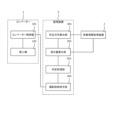
- FIG. 1 is a block diagram showing an elevator monitoring system according to Embodiment 1.
- FIG. FIG. 2 is an explanatory diagram showing a method of calculating the direction of rain blowing by the blowing direction calculation unit of FIG. 1;
- FIG. 2 is a configuration diagram showing a landing floor of a building where the elevator monitoring system of FIG. 1 is installed.
- FIG. 4 is an explanatory diagram showing the direction in which the opening in FIG. 3 faces.
- 3 is a flowchart showing processing of the elevator monitoring system according to the first embodiment.
- FIG. 1 is a block diagram showing an elevator monitoring system according to the first embodiment.
- the elevator monitoring system according to the first embodiment includes an elevator 1, a weather information acquisition device 2, and a monitoring device 3.
- the elevator 1 includes an elevator control panel 101 and a hoist 102 controlled by the elevator control panel 101.
- An evacuation operation command and an evacuation operation cancellation command are input to the elevator control panel 101 from the monitoring device 3.
- the elevator control panel 101 controls the hoisting machine 102 so that the elevator 1 performs an evacuation operation.
- a car (not shown) moves to a preset floor, and then the elevator 1 enters a rest state.
- an evacuation operation cancellation command is input to the elevator control panel 101, the elevator control panel 101 controls the hoisting machine 102 so that the evacuation operation of the elevator 1 is canceled.
- the weather information acquisition device 2 is installed in the building where the elevator 1 is installed. Weather information in the area where the building in which the elevator 1 is installed is periodically input to the weather information acquisition device 2 from an information center (not shown). The weather information includes wind speed, wind direction, and rainfall amount per unit time. The weather information input to the weather information acquisition device 2 is output from the weather information acquisition device 2 and input to the monitoring device 3.
- the monitoring device 3 is installed in the building where the elevator 1 is installed.
- the monitoring device 3 includes a blowing direction calculation section 301, a water inundation amount calculation section 302, a determination processing section 303, and an operation control command section 304.
- the falling speed of rain changes depending on the size of the raindrops.
- the size of raindrops changes depending on the amount of rainfall per unit time. Therefore, the falling speed of rain changes depending on the amount of rainfall per unit time.
- the blowing direction calculation unit 301 stores in advance the falling speed of rain corresponding to the amount of rainfall per unit time.
- the weather information output from the weather information acquisition device 2 is input to the blowing direction calculation unit 301.
- the blowing direction calculation unit 301 determines the falling speed of rain using the amount of rainfall per unit time.
- FIG. 2 is an explanatory diagram showing a method of calculating the rain blowing direction ⁇ by the blowing direction calculation unit 301 of FIG.
- the blowing direction calculation unit 301 calculates the rain blowing direction ⁇ using the wind speed V w , the wind direction D w , and the rain falling speed V r .
- the wind direction D w is the direction of the wind along the horizontal plane.
- the falling speed of rain V r is the speed of rain in the vertical direction.
- the rain blowing direction ⁇ is calculated by the blowing direction calculation unit 301 as a three-dimensional vector from the wind speed V w , wind direction D w , and rain falling speed V r .
- the absolute value of the rain blowing direction ⁇ is 1.
- FIG. 3 is a configuration diagram showing a landing floor of a building where the elevator monitoring system of FIG. 1 is installed.
- a plurality of openings 401 are formed in the outer wall of the building 4. Rain enters the landing floor 402 from outside the building 4 through each opening 401.
- a hall entrance/exit 403 is formed in the building 4.
- the hall entrance/exit 403 is opened and closed by the hall door 103 of the elevator 1.
- the rain that has entered the landing floor 402 flows through the landing floor 402, passes through the landing doorway 403, and enters the not-shown hoistway of the elevator 1.
- the number of openings 401 is N, each opening 401 is numbered from 1 to N, any natural number from 1 to N is n, the area of the nth opening 401 is S n , and the nth Let ⁇ n be the direction in which the opening 401 faces. In FIG. 3, the number of openings 401 is twelve.
- the area S n of each of the plurality of openings 401 and the direction ⁇ n in which each opening 401 faces are stored in correspondence with each other.
- FIG. 4 is an explanatory diagram showing the direction ⁇ n in which the opening 401 in FIG. 3 faces.
- the direction ⁇ n in which the opening 401 faces is a three-dimensional vector.
- the absolute value of the direction ⁇ n in which the opening 401 faces is 1.
- the direction ⁇ n in which each opening 401 faces is a direction perpendicular to the outer wall of the building 4 in which each opening 401 is formed, and is a direction from the outside of the building 4 to the inside.
- FIG. 3 shows a structure of a building 4 in which the direction ⁇ n of all of the plurality of openings 401 is along a horizontal plane. Note that among the plurality of openings 401, there are openings 401 in which the direction ⁇ n in which the opening 401 faces is inclined with respect to the horizontal plane, or openings 401 in which the direction ⁇ n in which the opening 401 faces is in the vertical direction. May be included.
- the amount of rainfall R per unit time is input to the inundation amount calculation unit 302.
- the inundation amount calculation unit 302 uses the area S n of each opening 401, the direction ⁇ n in which each opening 401 faces, the rain blowing direction ⁇ , and the rainfall amount R per unit time to The amount A of rain that enters the building 4 through the section 401 per unit time is calculated.
- the inundation amount calculation unit 302 first calculates the amount of rain blown in per unit area of each opening 401 ⁇ n using the following equation (1).
- the inundation amount calculation unit 302 calculates the value calculated by the above formula (1) by calculating the amount of rain per unit area in the opening 401. It is stored as the blowing amount ⁇ n .
- the inundation amount calculation unit 302 stores 0 as the amount of rain blown into the opening 401 per unit area ⁇ n . If the value calculated by the above formula (1) is a negative value, the wind direction D w is directed from the inside of the building 4 to the outside with respect to the opening 401, and the rain passes through the opening 401 and towards the outside of the building 4. It doesn't fit into 4.
- the inundation amount calculation unit 302 calculates the amount A of rain per unit time that has entered the building 4 using the following equation (2).
- the calculation result of the flood amount calculation unit 302 is input to the determination processing unit 303.
- the determination processing unit 303 is preset with a first threshold value used to determine whether to perform evacuation operation, and a second threshold value used to determine whether or not to cancel evacuation operation.
- the second threshold is a smaller value than the first threshold.
- the first threshold value and the second threshold value are determined according to the wastewater treatment capacity of the hoistway of the building 4.
- the determination processing unit 303 determines whether the amount A of rain per unit time that has entered the building 4, calculated by the inundation amount calculation unit 302, exceeds a first threshold value.
- the determination processing unit 303 determines whether the amount A of rain per unit time that has entered the building 4, calculated by the inundation amount calculation unit 302, is less than the second threshold value.
- the determination result of the determination processing unit 303 is input to the operation control command unit 304.
- the operation control command unit 304 outputs an evacuation operation command.
- the evacuation operation command output from the operation control command section 304 is input to the elevator control panel 101.
- the elevator control panel 101 controls the hoisting machine 102 so that the elevator 1 performs an evacuation operation.
- the operation control command unit 304 After the operation control command unit 304 outputs the evacuation operation command, if the determination processing unit 303 determines that the amount A of rain per unit time that has entered the building 4 is less than the second threshold, the operation control command unit 304 outputs an evacuation operation cancellation command.
- the evacuation operation cancellation command output from the operation control command unit 304 is input to the elevator control panel 101.
- the elevator control panel 101 controls the hoisting machine 102 so that the evacuation operation of the elevator 1 is canceled.
- FIG. 5 is a flowchart showing processing of the elevator monitoring system according to the first embodiment.
- step S101 a blowing direction calculation step is performed.
- the blowing direction calculation unit 301 calculates the rain blowing direction ⁇ using the wind speed V w , the wind direction D w , and the rain falling speed V r .
- the blowing direction calculation step is performed every time weather information is input to the blowing direction calculating section 301.
- step S102 a flood amount calculation step is performed.
- the inundation amount calculation unit 302 calculates the area S n of the opening 401 formed in the building 4, the direction ⁇ n in which the opening 401 faces, the calculated rain blowing direction ⁇ , and the per unit time.
- the rainfall amount R the amount A of rain per unit time that enters the building 4 is calculated.
- the flood amount calculation process is performed every time the blowing direction calculation process is performed.
- step S103 an evacuation determination processing step is performed.
- the determination processing unit 303 determines whether the amount A of rain per unit time that has entered the building 4 exceeds a first threshold value.
- step S103 when the determination processing unit 303 determines that the amount A of rain per unit time that has entered the building 4 does not exceed the first threshold, the process of the elevator monitoring system according to the first embodiment , step S103 is repeated.
- the evacuation determination processing step the amount A of rain per unit time that has entered the building 4, which is calculated in the latest inundation amount calculation step, is used.
- step S103 when the determination processing unit 303 determines that the amount A of rain per unit time that has entered the building 4 exceeds the first threshold, the process of the elevator monitoring system according to the first embodiment Then, the process advances to step S104.
- step S104 an evacuation operation command process is performed.
- an evacuation operation command is output from the operation control command section 304, and the output evacuation operation command is input to the elevator control panel 101. Thereby, the elevator 1 performs evacuation operation.
- step S104 the process of the elevator monitoring system according to the first embodiment proceeds to step S105.
- step S105 a cancellation determination processing step is performed.
- the determination processing unit 303 determines whether the amount A of rain per unit time that has entered the building 4 has fallen below the second threshold.
- step S105 when the determination processing unit 303 determines that the amount A of rain per unit time that has entered the building 4 is not less than the second threshold, the process of the elevator monitoring system according to the first embodiment , step S105 is repeated.
- the cancellation determination processing step the amount A of rain per unit time that has entered the building 4, which is calculated in the latest inundation amount calculation step, is used.
- step S105 when the determination processing unit 303 determines that the amount A of rain per unit time that has entered the building 4 is less than the second threshold, the process of the elevator monitoring system according to the first embodiment Then, the process advances to step S106.
- step S106 an evacuation operation command cancellation step is performed.
- the evacuation operation command cancellation step an evacuation operation cancellation command is output from the operation control command section 304, and the output evacuation operation cancellation command is input to the elevator control panel 101. Thereby, the elevator 1 cancels the evacuation operation.
- the elevator monitoring system includes a blowing direction calculation section 301, a water inundation amount calculation section 302, a determination processing section 303, and an operation control command section 304.
- the blowing direction calculation unit 301 calculates the rain blowing direction ⁇ using the wind speed V w , the wind direction D w , and the rain falling speed V r .
- the inundation amount calculation unit 302 uses the area S n of the opening 401 formed in the building 4, the direction ⁇ n in which the opening 401 faces, the calculated rain blowing direction ⁇ , and the rainfall amount R per unit time. Then, the amount A of rain that enters the building 4 per unit time is calculated.
- the determination processing unit 303 determines whether the amount A of rain per unit time that has entered the building 4 exceeds a first threshold value.
- the operation control command unit 304 outputs an evacuation operation command to the elevator 1 based on the determination result of the determination processing unit 303. According to this configuration, using the area S n of the opening 401 formed in the building 4, the direction ⁇ n in which the opening 401 faces, the calculated rain blowing direction ⁇ , and the rainfall amount R per unit time, , the amount A of rain per unit time that enters the building 4 is calculated. Thereby, the accuracy of calculating the amount A of rain per unit time that enters the building 4 can be improved.
- the blowing direction calculation unit 301 determines the falling speed V r of rain using the rainfall amount R per unit time. According to this configuration, the accuracy of calculating the rain blowing direction ⁇ can be further improved.
- the elevator monitoring method includes a blow direction calculation step, a water inundation amount calculation step, an evacuation determination processing step, and an operation control command step.
- the rain blowing direction ⁇ is calculated using the wind speed V w , the wind direction D w , and the rain falling speed V r .
- the flooding amount calculation step is performed after the blowing direction calculation step.
- the inundation amount calculation step the area S n of the opening 401 formed in the building 4, the direction ⁇ n in which the opening 401 faces, the calculated rain blowing direction ⁇ , and the rainfall amount R per unit time are used. , the amount A of rain per unit time that enters the building 4 is calculated.
- the evacuation determination processing step is performed after the flooding amount calculation step.
- the evacuation determination processing step it is determined whether the amount A of rain per unit time that has entered the building 4 exceeds a first threshold value.
- the operation control command step is performed after the evacuation determination processing step.
- an evacuation operation command is output to the elevator 1 based on the determination result of the evacuation determination processing step.
- the elevator monitoring method includes a cancellation determination processing step and an evacuation operation command cancellation step.
- the cancellation determination processing step is performed after the evacuation operation command step.
- the evacuation operation command cancellation step is performed after the cancellation determination processing step.
- an evacuation operation cancellation command is output to the elevator 1 based on the determination result of the cancellation determination processing step.
- the blowing direction calculation unit 301 determines the falling speed V r of rain using the rainfall amount R per unit time.
- the blowing direction calculation unit 301 may be configured to calculate the rain falling speed V r using the rainfall amount R per unit time and a preset calculation formula.
- the blowing direction calculation unit 301 may be configured to calculate the rain blowing direction ⁇ by setting the rain falling speed V r to a constant value. In this case, there is no need for the blowing direction calculation unit 301 to determine or calculate the falling speed V r of the rain.
- the weather information acquisition device 2 is provided in the building 4 in which the elevator 1 is installed.
- a configuration may also be adopted in which the weather information acquisition device 2 is provided outside the building 4.
- the weather information acquisition device 2 may be provided in the information center.
- the weather information acquisition device 2 includes at least one of an anemometer, a wind vane, and a rain gauge, and measures at least one of wind speed V w , wind direction D w , and rainfall amount R per unit time.
- the configuration may be such that
- the monitoring device 3 is provided in the building 4 in which the elevator 1 is installed.
- a configuration in which the monitoring device 3 is provided outside the building 4 may also be used.
- the information center may be provided with the monitoring device 3.
- Elevator 1 Elevator, 2 Weather information acquisition device, 3 Monitoring device, 4 Building, 101 Elevator control panel, 102 Hoisting machine, 103 Landing door, 301 Blowing direction calculation unit, 302 Inundation amount calculation unit, 303 Judgment processing unit, 304 Operation control Command department, 401 opening, 402 landing floor, 403 landing entrance.
Landscapes
- Engineering & Computer Science (AREA)
- Automation & Control Theory (AREA)
- Maintenance And Inspection Apparatuses For Elevators (AREA)
- Indicating And Signalling Devices For Elevators (AREA)
Abstract
建物の中に入った雨の量の算出の精度を向上させることができるエレベーター監視システムを得る。このエレベーター監視システムは、風速、風向、および、雨の落下速度を用いて、雨の吹込方向を算出する吹込方向算出部と、建物に形成された開口部の面積、開口部が向く方向、算出された雨の吹込方向、および、単位時間当たりの降雨量を用いて、開口部を通って建物の中に入った単位時間当たりの雨の量を算出する浸水量算出部と、単位時間当たりの雨の量が予め設定された第1閾値を超えたか否かを判定する判定処理部と、判定処理部の判定結果に基づいて、エレベーターに対して退避運転指令を出力する運転制御指令部と、を備えている。
Description
本開示は、エレベーター監視システムおよびエレベーター監視方法に関する。
従来、風速、風向、および、単位時間当たりの降雨量を用いて、エレベーターが退避運転を行うか否かを判定するエレベーター監視システムが知られている(例えば、特許文献1参照)。
特許文献1に記載された構成では、風速、風向、および、単位時間当たりの降雨量を用いて、建物の中に入った雨の量に基づいた損害リスクが算出され、算出された損害リスクに基づいて、エレベーターが退避運転を行うか否かが判定されている。しかしながら、建物に形成された開口部の面積および開口部が向く方向と、雨の吹込方向との関係によって、建物の中に入る雨の量が変化する。したがって、特許文献1に記載された構成では、建物の中に入った雨の量における算出の精度が低いという問題点があった。
本開示は、上述のような課題を解決するためになされたものであり、その目的は、建物の中に入った雨の量の算出の精度を向上させることができるエレベーター監視システムおよびエレベーター監視方法を提供するものである。
本開示に係るエレベーター監視システムは、風速、風向、および、雨の落下速度を用いて、雨の吹込方向を算出する吹込方向算出部と、建物に形成された開口部の面積、開口部が向く方向、算出された雨の吹込方向、および、単位時間当たりの降雨量を用いて、開口部を通って建物の中に入った単位時間当たりの雨の量を算出する浸水量算出部と、単位時間当たりの雨の量が予め設定された第1閾値を超えたか否かを判定する判定処理部と、判定処理部の判定結果に基づいて、エレベーターに対して退避運転指令を出力する運転制御指令部と、を備えている。
本開示に係るエレベーター監視方法は、風速、風向、および、雨の落下速度を用いて、雨の吹込方向を算出する吹込方向算出工程と、吹込方向算出工程の後、建物に形成された開口部の面積、開口部が向く方向、算出された雨の吹込方向、および、単位時間当たりの降雨量を用いて、開口部を通って建物の中に入った単位時間当たりの雨の量を算出する浸水量算出工程と、浸水量算出工程の後、単位時間当たりの雨の量が予め設定された第1閾値を超えたか否かを判定する退避判定処理工程と、退避判定処理工程の後、退避判定処理工程の判定結果に基づいて、エレベーターに対して退避運転指令を出力する退避運転指令工程と、を備えている。
本開示に係るエレベーター監視方法は、風速、風向、および、雨の落下速度を用いて、雨の吹込方向を算出する吹込方向算出工程と、吹込方向算出工程の後、建物に形成された開口部の面積、開口部が向く方向、算出された雨の吹込方向、および、単位時間当たりの降雨量を用いて、開口部を通って建物の中に入った単位時間当たりの雨の量を算出する浸水量算出工程と、浸水量算出工程の後、単位時間当たりの雨の量が予め設定された第1閾値を超えたか否かを判定する退避判定処理工程と、退避判定処理工程の後、退避判定処理工程の判定結果に基づいて、エレベーターに対して退避運転指令を出力する退避運転指令工程と、を備えている。
本開示に係るエレベーター監視システムおよびエレベーター監視方法によれば、建物の中に入った雨の量の算出の精度を向上させることができる。
実施の形態1.
図1は、実施の形態1に係るエレベーター監視システムを示すブロック図である。実施の形態1に係るエレベーター監視システムは、エレベーター1と、気象情報取得装置2と、監視装置3と、を備えている。
図1は、実施の形態1に係るエレベーター監視システムを示すブロック図である。実施の形態1に係るエレベーター監視システムは、エレベーター1と、気象情報取得装置2と、監視装置3と、を備えている。
エレベーター1は、エレベーター制御盤101と、エレベーター制御盤101によって制御される巻上機102と、を備えている。エレベーター制御盤101には、後述する退避運転指令および退避運転解除指令が監視装置3から入力されるようになっている。エレベーター制御盤101に退避運転指令が入力された場合に、エレベーター制御盤101は、エレベーター1が退避運転を行うように巻上機102を制御する。エレベーター1の退避運転では、図示しないかごが予め設定された階に移動し、その後、エレベーター1が休止状態になる。エレベーター制御盤101に退避運転解除指令が入力された場合に、エレベーター制御盤101は、エレベーター1の退避運転が解除されるように巻上機102を制御する。
気象情報取得装置2は、エレベーター1が設置されている建物に設けられている。気象情報取得装置2には、図示しない情報センタから、エレベーター1が設置されている建物がある地域における気象情報が定期的に入力される。気象情報には、風速、風向、および、単位時間当たりの降雨量が含まれている。気象情報取得装置2に入力された気象情報は、気象情報取得装置2から出力されて、監視装置3に入力される。
監視装置3は、エレベーター1が設置されている建物に設けられている。監視装置3は、吹込方向算出部301と、浸水量算出部302と、判定処理部303と、運転制御指令部304と、を備えている。
雨の落下速度は、雨粒の大きさによって変化する。雨粒の大きさは、単位時間当たりの降雨量によって変化する。したがって、雨の落下速度は、単位時間当たりの降雨量によって変化する。
吹込方向算出部301には、単位時間当たりの降雨量に対応した雨の落下速度が予め記憶されている。気象情報取得装置2から出力された気象情報は、吹込方向算出部301に入力される。吹込方向算出部301は、単位時間当たりの降雨量を用いて、雨の落下速度を決定する。
図2は、図1の吹込方向算出部301による雨の吹込方向αの算出方法を示す説明図である。吹込方向算出部301は、風速Vw、風向Dw、および、雨の落下速度Vrを用いて、雨の吹込方向αを算出する。風向Dwは、水平面に沿った風の方向となっている。雨の落下速度Vrは、鉛直方向における雨の速度となっている。
雨の吹込方向αは、風速Vw、風向Dw、および、雨の落下速度Vrから、三次元のベクトルとして吹込方向算出部301によって算出される。雨の吹込方向αの絶対値は、1となっている。
図3は、図1のエレベーター監視システムが設置されている建物の乗場フロアを示す構成図である。建物4の外壁には、複数の開口部401が形成されている。それぞれの開口部401を通って、建物4の外側から雨が乗場フロア402に浸入する。
建物4には、乗場出入口403が形成されている。乗場出入口403は、エレベーター1の乗場ドア103によって開閉される。乗場フロア402に浸入した雨は、乗場フロア402を流れ、乗場出入口403を通って、エレベーター1における図示しない昇降路に浸入する。
開口部401の数をNとし、それぞれの開口部401に1~Nの番号を設定し、1~Nの任意の自然数をnとし、n番目の開口部401の面積をSnとし、n番目の開口部401が向く方向をβnとする。図3では、開口部401の数が12となっている。
浸水量算出部302には、複数の開口部401のそれぞれの面積Snと、それぞれの開口部401が向く方向βnとが互いに対応して記憶されている。
図4は、図3の開口部401が向く方向βnを示す説明図である。開口部401が向く方向βnは、三次元のベクトルとなっている。開口部401が向く方向βnの絶対値は、1となっている。それぞれの開口部401が向く方向βnは、それぞれの開口部401が形成されている建物4の外壁に垂直な方向であって、建物4の外側から内側に向かう方向とする。
図3には、複数の開口部401の全てにおいて、開口部401が向く方向βnが水平面に沿った方向となっている建物4の構成が示されている。なお、複数の開口部401の中には、開口部401が向く方向βnが水平面に対して傾斜する開口部401、または、開口部401が向く方向βnが鉛直方向となる開口部401が含まれてもよい。
気象情報取得装置2から出力された気象情報のうちの単位時間当たりの降雨量Rは、浸水量算出部302に入力される。浸水量算出部302は、それぞれの開口部401の面積Sn、それぞれの開口部401が向く方向βn、雨の吹込方向α、および、単位時間当たりの降雨量Rを用いて、それぞれの開口部401を通って建物4の中に入った単位時間当たりの雨の量Aを算出する。
具体的には、浸水量算出部302は、まず、下記の式(1)を用いて、それぞれの開口部401における単位面積当たりの雨の吹込量φnを算出する。
φn=α・βn (1)
浸水量算出部302は、上記の式(1)によって算出された値が正の値の場合には、上記の式(1)によって算出された値を、開口部401における単位面積当たりの雨の吹込量φnとして記憶する。
一方、浸水量算出部302は、上記の式(1)によって算出された値が負の値の場合には、0を開口部401における単位面積当たりの雨の吹込量φnとして記憶する。上記の式(1)によって算出された値が負の値の場合には、風向Dwが開口部401に対して建物4の内側から外側に向かう向きとなり、雨が開口部401を通って建物4の中に入らない。
その後、浸水量算出部302は、下記の式(2)を用いて、建物4の中に入った単位時間当たりの雨の量Aを算出する。

浸水量算出部302の算出結果は、判定処理部303に入力される。判定処理部303には、退避運転を行うか否かの判定に用いられる第1閾値と、退避運転を解除するか否かの判定の用いられる第2閾値とが予め設定されている。第2閾値は、第1閾値よりも小さい値となっている。第1閾値および第2閾値は、建物4の昇降路における排水処理能力に応じて決められている。
判定処理部303は、浸水量算出部302によって算出された、建物4の中に入った単位時間当たりの雨の量Aが第1閾値を超えたか否かを判定する。
また、判定処理部303は、浸水量算出部302によって算出された、建物4の中に入った単位時間当たりの雨の量Aが第2閾値を下回ったか否かを判定する。
判定処理部303の判定結果は、運転制御指令部304に入力される。建物4の中に入った単位時間当たりの雨の量Aが第1閾値を超えたと判定処理部303が判定した場合に、運転制御指令部304は、退避運転指令を出力する。運転制御指令部304から出力された退避運転指令は、エレベーター制御盤101に入力される。退避運転指令がエレベーター制御盤101に入力された場合に、エレベーター制御盤101は、エレベーター1が退避運転を行うように巻上機102を制御する。
運転制御指令部304が退避運転指令を出力した後に、建物4の中に入った単位時間当たりの雨の量Aが第2閾値を下回ったと判定処理部303が判定した場合に、運転制御指令部304は、退避運転解除指令を出力する。運転制御指令部304から出力された退避運転解除指令は、エレベーター制御盤101に入力される。退避運転解除指令がエレベーター制御盤101に入力された場合に、エレベーター制御盤101は、エレベーター1の退避運転が解除されるように巻上機102を制御する。
次に、実施の形態1に係るエレベーター監視システムにおけるエレベーター監視方法について説明する。図5は、実施の形態1に係るエレベーター監視システムの処理を示すフローチャートである。まず、ステップS101において、吹込方向算出工程が行われる。吹込方向算出工程では、吹込方向算出部301は、風速Vw、風向Dw、および、雨の落下速度Vrを用いて、雨の吹込方向αを算出する。吹込方向算出工程は、気象情報が吹込方向算出部301に入力される度に行われる。
その後、ステップS102において、浸水量算出工程が行われる。浸水量算出工程では、浸水量算出部302は、建物4に形成された開口部401の面積Sn、開口部401が向く方向βn、算出された雨の吹込方向α、および、単位時間当たりの降雨量Rを用いて、建物4の中に入った単位時間当たりの雨の量Aを算出する。浸水量算出工程は、吹込方向算出工程が行われる度に行われる。
その後、ステップS103において、退避判定処理工程が行われる。退避判定処理工程では、判定処理部303は、建物4の中に入った単位時間当たりの雨の量Aが第1閾値を超えたか否かを判定する。ステップS103において、建物4の中に入った単位時間当たりの雨の量Aが第1閾値を超えていないと判定処理部303に判定された場合に、実施の形態1に係るエレベーター監視システムの処理は、ステップS103が繰り返される。退避判定処理工程では、最新の浸水量算出工程によって算出された、建物4の中に入った単位時間当たりの雨の量Aが用いられる。
一方、ステップS103において、建物4の中に入った単位時間当たりの雨の量Aが第1閾値を超えたと判定処理部303に判定された場合に、実施の形態1に係るエレベーター監視システムの処理は、ステップS104に進む。
ステップS104では、退避運転指令工程が行われる。退避運転指令工程では、運転制御指令部304から退避運転指令が出力され、出力された退避運転指令がエレベーター制御盤101に入力される。これにより、エレベーター1は、退避運転を行う。
ステップS104の後、実施の形態1に係るエレベーター監視システムの処理は、ステップS105に進む。
ステップS105では、解除判定処理工程が行われる。解除判定処理工程では、判定処理部303は、建物4の中に入った単位時間当たりの雨の量Aが第2閾値を下回ったか否かを判定する。ステップS105において、建物4の中に入った単位時間当たりの雨の量Aが第2閾値を下回っていないと判定処理部303に判定された場合に、実施の形態1に係るエレベーター監視システムの処理は、ステップS105が繰り返される。解除判定処理工程では、最新の浸水量算出工程によって算出された、建物4の中に入った単位時間当たりの雨の量Aが用いられる。
一方、ステップS105において、建物4の中に入った単位時間当たりの雨の量Aが第2閾値を下回ったと判定処理部303に判定された場合に、実施の形態1に係るエレベーター監視システムの処理は、ステップS106に進む。
ステップS106では、退避運転指令解除工程が行われる。退避運転指令解除工程では、運転制御指令部304から退避運転解除指令が出力され、出力された退避運転解除指令がエレベーター制御盤101に入力される。これにより、エレベーター1は、退避運転を解除する。以上により、実施の形態1に係るエレベーター監視システムの処理が終了する。
以上説明したように、実施の形態1に係るエレベーター監視システムは、吹込方向算出部301と、浸水量算出部302と、判定処理部303と、運転制御指令部304と、を備えている。吹込方向算出部301は、風速Vw、風向Dw、および、雨の落下速度Vrを用いて、雨の吹込方向αを算出する。浸水量算出部302は、建物4に形成された開口部401の面積Sn、開口部401が向く方向βn、算出された雨の吹込方向α、および、単位時間当たりの降雨量Rを用いて、建物4の中に入った単位時間当たりの雨の量Aを算出する。判定処理部303は、建物4の中に入った単位時間当たりの雨の量Aが第1閾値を超えたか否かを判定する。運転制御指令部304は、判定処理部303の判定結果に基づいて、エレベーター1に対して退避運転指令を出力する。この構成によれば、建物4に形成された開口部401の面積Sn、開口部401が向く方向βn、算出された雨の吹込方向α、および、単位時間当たりの降雨量Rを用いて、建物4の中に入った単位時間当たりの雨の量Aが算出される。これにより、建物4の中に入った単位時間当たりの雨の量Aの算出の精度を向上させることができる。
建物4の中に入った単位時間当たりの雨の量Aの算出の精度が向上することによって、エレベーター1が設置されている昇降路に溜まった水の中にかごが入ってしまうことを抑制することができ、エレベーター1の故障の発生を低減させることができる。また、建物4の中に入った単位時間当たりの雨の量Aの算出の精度が向上することによって、無駄なエレベーター1の退避運転を回避することができ、エレベーター1の稼働率を向上させることができる。その結果、エレベーター1の利用者に対する利便性を向上させることができる。
また、吹込方向算出部301は、単位時間当たりの降雨量Rを用いて、雨の落下速度Vrを決定する。この構成によれば、雨の吹込方向αの算出の精度をより向上させることができる。
また、実施の形態1に係るエレベーター監視方法は、吹込方向算出工程と、浸水量算出工程と、退避判定処理工程と、運転制御指令工程と、を備えている。吹込方向算出工程では、風速Vw、風向Dw、および、雨の落下速度Vrを用いて、雨の吹込方向αを算出する。浸水量算出工程は、吹込方向算出工程の後に行われる。浸水量算出工程では、建物4に形成された開口部401の面積Sn、開口部401が向く方向βn、算出された雨の吹込方向α、および、単位時間当たりの降雨量Rを用いて、建物4の中に入った単位時間当たりの雨の量Aを算出する。退避判定処理工程は、浸水量算出工程の後に行われる。退避判定処理工程では、建物4の中に入った単位時間当たりの雨の量Aが第1閾値を超えたか否かを判定する。運転制御指令工程は、退避判定処理工程の後に行われる。運転制御指令工程では、退避判定処理工程の判定結果に基づいて、エレベーター1に対して退避運転指令を出力する。この構成によれば、建物4に形成された開口部401の面積Sn、開口部401が向く方向βn、算出された雨の吹込方向α、および、単位時間当たりの降雨量Rを用いて、建物4の中に入った単位時間当たりの雨の量Aが算出される。これにより、建物4の中に入った単位時間当たりの雨の量Aの算出の精度を向上させることができる。
また、実施の形態1に係るエレベーター監視方法は、解除判定処理工程と、退避運転指令解除工程と、を備えいる。解除判定処理工程は、退避運転指令工程の後に行われる。解除判定処理工程では、建物4の中に入った単位時間当たりの雨の量Aが第2閾値を下回ったか否かを判定する。退避運転指令解除工程は、解除判定処理工程の後に行われる。退避運転指令解除工程では、解除判定処理工程の判定結果に基づいて、エレベーター1に対して退避運転解除指令を出力する。この構成によれば、エレベーター1が退避運転を行った後、建物4の中に入った単位時間当たりの雨の量Aが第2閾値を下回った場合に、エレベーター1の退避運転を解除することができる。
なお、実施の形態1に係るエレベーター監視システムでは、吹込方向算出部301が単位時間当たりの降雨量Rを用いて雨の落下速度Vrを決定する構成について説明した。しかしながら、吹込方向算出部301が単位時間当たりの降雨量Rおよび予め設定された計算式を用いて雨の落下速度Vrを算出する構成であってもよい。また、吹込方向算出部301は、雨の落下速度Vrを一定の値にして、雨の吹込方向αを算出する構成であってもよい。この場合に、吹込方向算出部301による雨の落下速度Vrの決定または算出が不要となる。
また、実施の形態1に係るエレベーター監視システムでは、エレベーター1が設置されている建物4に気象情報取得装置2が設けられている構成について説明した。しかしながら、建物4の外側に気象情報取得装置2が設けられている構成であってもよい。この場合に、例えば、情報センタに気象情報取得装置2が設けられている構成であってもよい。
また、実施の形態1に係るエレベーター監視システムでは、情報センタから気象情報取得装置2に気象情報が入力される構成について説明した。しかしながら、気象情報取得装置2が、風速計、風向計、および、雨量計の少なくとも1つを有し、風速Vw、風向Dw、および、単位時間当たりの降雨量Rの少なくとも1つを測定する構成であってもよい。
また、実施の形態1に係るエレベーター監視システムでは、エレベーター1が設置されている建物4に監視装置3が設けられている構成について説明した。しかしながら、建物4の外側に監視装置3が設けられている構成であってもよい。この場合に、例えば、情報センタに監視装置3が設けられている構成であってもよい。
1 エレベーター、2 気象情報取得装置、3 監視装置、4 建物、101 エレベーター制御盤、102 巻上機、103 乗場ドア、301 吹込方向算出部、302 浸水量算出部、303 判定処理部、304 運転制御指令部、401 開口部、402 乗場フロア、403 乗場出入口。
Claims (4)
- 風速、風向、および、雨の落下速度を用いて、雨の吹込方向を算出する吹込方向算出部と、
建物に形成された開口部の面積、前記開口部が向く方向、算出された前記雨の吹込方向、および、単位時間当たりの降雨量を用いて、前記開口部を通って前記建物の中に入った単位時間当たりの雨の量を算出する浸水量算出部と、
前記単位時間当たりの雨の量が予め設定された第1閾値を超えたか否かを判定する判定処理部と、
前記判定処理部の判定結果に基づいて、エレベーターに対して退避運転指令を出力する運転制御指令部と、
を備えているエレベーター監視システム。 - 前記吹込方向算出部は、前記単位時間当たりの降雨量を用いて、前記雨の落下速度を決定する請求項1に記載のエレベーター監視システム。
- 風速、風向、および、雨の落下速度を用いて、雨の吹込方向を算出する吹込方向算出工程と、
前記吹込方向算出工程の後、建物に形成された開口部の面積、前記開口部が向く方向、算出された前記雨の吹込方向、および、単位時間当たりの降雨量を用いて、前記開口部を通って前記建物の中に入った単位時間当たりの雨の量を算出する浸水量算出工程と、
前記浸水量算出工程の後、前記単位時間当たりの雨の量が予め設定された第1閾値を超えたか否かを判定する退避判定処理工程と、
前記退避判定処理工程の後、前記退避判定処理工程の判定結果に基づいて、エレベーターに対して退避運転指令を出力する退避運転指令工程と、
を備えているエレベーター監視方法。 - 前記退避運転指令工程の後、前記単位時間当たりの雨の量が予め設定された第2閾値を下回ったか否かを判定する解除判定処理工程と、
前記解除判定処理工程の後、前記解除判定処理工程の判定結果に基づいて、エレベーターに対して退避運転解除指令を出力する退避運転指令解除工程と、
をさらに備えている請求項3に記載のエレベーター監視方法。
Priority Applications (2)
| Application Number | Priority Date | Filing Date | Title |
|---|---|---|---|
| PCT/JP2022/031248 WO2024038552A1 (ja) | 2022-08-18 | 2022-08-18 | エレベーター監視システムおよびエレベーター監視方法 |
| JP2024541349A JP7657373B2 (ja) | 2022-08-18 | 2022-08-18 | エレベーター監視システムおよびエレベーター監視方法 |
Applications Claiming Priority (1)
| Application Number | Priority Date | Filing Date | Title |
|---|---|---|---|
| PCT/JP2022/031248 WO2024038552A1 (ja) | 2022-08-18 | 2022-08-18 | エレベーター監視システムおよびエレベーター監視方法 |
Publications (1)
| Publication Number | Publication Date |
|---|---|
| WO2024038552A1 true WO2024038552A1 (ja) | 2024-02-22 |
Family
ID=89941491
Family Applications (1)
| Application Number | Title | Priority Date | Filing Date |
|---|---|---|---|
| PCT/JP2022/031248 Ceased WO2024038552A1 (ja) | 2022-08-18 | 2022-08-18 | エレベーター監視システムおよびエレベーター監視方法 |
Country Status (2)
| Country | Link |
|---|---|
| JP (1) | JP7657373B2 (ja) |
| WO (1) | WO2024038552A1 (ja) |
Citations (3)
| Publication number | Priority date | Publication date | Assignee | Title |
|---|---|---|---|---|
| JPH0172554U (ja) * | 1987-11-05 | 1989-05-16 | ||
| JPH06171857A (ja) * | 1992-12-08 | 1994-06-21 | Hitachi Building Syst Eng & Service Co Ltd | 水害時のエレベータ避難運転装置 |
| JP2008280737A (ja) * | 2007-05-10 | 2008-11-20 | Toyota Motor Corp | 電動シャッタ制御装置、及びそれを備えた建物 |
-
2022
- 2022-08-18 JP JP2024541349A patent/JP7657373B2/ja active Active
- 2022-08-18 WO PCT/JP2022/031248 patent/WO2024038552A1/ja not_active Ceased
Patent Citations (3)
| Publication number | Priority date | Publication date | Assignee | Title |
|---|---|---|---|---|
| JPH0172554U (ja) * | 1987-11-05 | 1989-05-16 | ||
| JPH06171857A (ja) * | 1992-12-08 | 1994-06-21 | Hitachi Building Syst Eng & Service Co Ltd | 水害時のエレベータ避難運転装置 |
| JP2008280737A (ja) * | 2007-05-10 | 2008-11-20 | Toyota Motor Corp | 電動シャッタ制御装置、及びそれを備えた建物 |
Also Published As
| Publication number | Publication date |
|---|---|
| JPWO2024038552A1 (ja) | 2024-02-22 |
| JP7657373B2 (ja) | 2025-04-04 |
Similar Documents
| Publication | Publication Date | Title |
|---|---|---|
| CN103030042B (zh) | 电梯设备 | |
| US8490753B2 (en) | Elevator control apparatus with speed control to alleviate passenger ear block discomfort | |
| CN113148807B (zh) | 用于操作电梯的方法 | |
| JP5014623B2 (ja) | エレベーターの地震管制運転システム及びエレベーターの地震管制運転方法 | |
| CN101172550B (zh) | 电梯设备 | |
| EP1873106A1 (en) | Elevator group management and control device | |
| CN101391718A (zh) | 电梯设备 | |
| US20190284019A1 (en) | Elevator operation for occupancy | |
| CN104169204A (zh) | 电梯系统 | |
| JP7649651B2 (ja) | エレベータの運転方法 | |
| JP7657373B2 (ja) | エレベーター監視システムおよびエレベーター監視方法 | |
| CN1239371C (zh) | 控制电梯组的方法 | |
| CN110077926B (zh) | 电梯及其减振机构调整方法 | |
| JPWO2017103968A1 (ja) | エレベーターの制御装置 | |
| CN117425610A (zh) | 电梯的管理系统以及电梯系统 | |
| JP2009161288A (ja) | エレベータ制御装置 | |
| JP6576558B2 (ja) | エレベータの制御装置および制御方法 | |
| KR102562729B1 (ko) | 엘리베이터 장치 | |
| JPH0640675A (ja) | エレベータの乗降人数検出装置およびエレベータ制御装置 | |
| JP2002206400A (ja) | トンネル換気制御装置 | |
| KR102658698B1 (ko) | 엘리베이터의 제어 장치 | |
| WO2024053011A1 (ja) | エレベーター監視システムおよびエレベーター監視方法 | |
| JP7243939B2 (ja) | 管制装置およびエレベーターシステム | |
| JPWO2018235156A1 (ja) | エレベータ装置 | |
| JP6648864B1 (ja) | エレベーター装置 |
Legal Events
| Date | Code | Title | Description |
|---|---|---|---|
| 121 | Ep: the epo has been informed by wipo that ep was designated in this application |
Ref document number: 22955726 Country of ref document: EP Kind code of ref document: A1 |
|
| WWE | Wipo information: entry into national phase |
Ref document number: 2024541349 Country of ref document: JP |
|
| NENP | Non-entry into the national phase |
Ref country code: DE |
|
| 122 | Ep: pct application non-entry in european phase |
Ref document number: 22955726 Country of ref document: EP Kind code of ref document: A1 |