WO2024034573A1 - Communication method and relay device - Google Patents
Communication method and relay device Download PDFInfo
- Publication number
- WO2024034573A1 WO2024034573A1 PCT/JP2023/028767 JP2023028767W WO2024034573A1 WO 2024034573 A1 WO2024034573 A1 WO 2024034573A1 JP 2023028767 W JP2023028767 W JP 2023028767W WO 2024034573 A1 WO2024034573 A1 WO 2024034573A1
- Authority
- WO
- WIPO (PCT)
- Prior art keywords
- ncr
- control
- gnb
- fwd
- failure
- Prior art date
Links
- 238000004891 communication Methods 0.000 title claims abstract description 59
- 238000000034 method Methods 0.000 title claims abstract description 43
- 230000004044 response Effects 0.000 claims abstract description 43
- 238000010295 mobile communication Methods 0.000 claims description 24
- 230000007704 transition Effects 0.000 claims description 5
- 230000005540 biological transmission Effects 0.000 description 61
- 230000011664 signaling Effects 0.000 description 57
- 238000010586 diagram Methods 0.000 description 53
- 230000004913 activation Effects 0.000 description 16
- 230000003321 amplification Effects 0.000 description 14
- 238000003199 nucleic acid amplification method Methods 0.000 description 14
- 230000009849 deactivation Effects 0.000 description 12
- 230000006870 function Effects 0.000 description 10
- 230000008859 change Effects 0.000 description 9
- 238000012545 processing Methods 0.000 description 9
- 238000010408 sweeping Methods 0.000 description 5
- 238000009434 installation Methods 0.000 description 4
- 238000012544 monitoring process Methods 0.000 description 4
- 230000008569 process Effects 0.000 description 4
- 230000002776 aggregation Effects 0.000 description 3
- 238000004220 aggregation Methods 0.000 description 3
- 230000015572 biosynthetic process Effects 0.000 description 3
- 230000020411 cell activation Effects 0.000 description 3
- 230000009977 dual effect Effects 0.000 description 3
- 238000005516 engineering process Methods 0.000 description 3
- 238000013507 mapping Methods 0.000 description 3
- 239000000758 substrate Substances 0.000 description 3
- 230000001629 suppression Effects 0.000 description 3
- 235000019527 sweetened beverage Nutrition 0.000 description 3
- 101100533725 Mus musculus Smr3a gene Proteins 0.000 description 2
- 102100022310 SPRY domain-containing SOCS box protein 3 Human genes 0.000 description 2
- 230000006978 adaptation Effects 0.000 description 2
- 230000003044 adaptive effect Effects 0.000 description 2
- 238000013461 design Methods 0.000 description 2
- 239000011521 glass Substances 0.000 description 2
- 230000006872 improvement Effects 0.000 description 2
- 230000007774 longterm Effects 0.000 description 2
- 101150012404 spsb3 gene Proteins 0.000 description 2
- 101150049705 ssb3 gene Proteins 0.000 description 2
- 108700026140 MAC combination Proteins 0.000 description 1
- 101100274486 Mus musculus Cited2 gene Proteins 0.000 description 1
- 101150096622 Smr2 gene Proteins 0.000 description 1
- 230000003213 activating effect Effects 0.000 description 1
- 239000000969 carrier Substances 0.000 description 1
- 230000006835 compression Effects 0.000 description 1
- 238000007906 compression Methods 0.000 description 1
- 238000012217 deletion Methods 0.000 description 1
- 230000037430 deletion Effects 0.000 description 1
- 230000020169 heat generation Effects 0.000 description 1
- 239000011159 matrix material Substances 0.000 description 1
- 238000005259 measurement Methods 0.000 description 1
- 238000012986 modification Methods 0.000 description 1
- 230000004048 modification Effects 0.000 description 1
- 238000013021 overheating Methods 0.000 description 1
- 239000004065 semiconductor Substances 0.000 description 1
- 238000012546 transfer Methods 0.000 description 1
- 238000013519 translation Methods 0.000 description 1
- 238000004260 weight control Methods 0.000 description 1
Images


Classifications
-
- H—ELECTRICITY
- H04—ELECTRIC COMMUNICATION TECHNIQUE
- H04B—TRANSMISSION
- H04B17/00—Monitoring; Testing
- H04B17/40—Monitoring; Testing of relay systems
-
- H—ELECTRICITY
- H04—ELECTRIC COMMUNICATION TECHNIQUE
- H04B—TRANSMISSION
- H04B7/00—Radio transmission systems, i.e. using radiation field
- H04B7/14—Relay systems
- H04B7/15—Active relay systems
-
- H—ELECTRICITY
- H04—ELECTRIC COMMUNICATION TECHNIQUE
- H04W—WIRELESS COMMUNICATION NETWORKS
- H04W16/00—Network planning, e.g. coverage or traffic planning tools; Network deployment, e.g. resource partitioning or cells structures
- H04W16/24—Cell structures
- H04W16/26—Cell enhancers or enhancement, e.g. for tunnels, building shadow
-
- H—ELECTRICITY
- H04—ELECTRIC COMMUNICATION TECHNIQUE
- H04W—WIRELESS COMMUNICATION NETWORKS
- H04W16/00—Network planning, e.g. coverage or traffic planning tools; Network deployment, e.g. resource partitioning or cells structures
- H04W16/24—Cell structures
- H04W16/28—Cell structures using beam steering
-
- H—ELECTRICITY
- H04—ELECTRIC COMMUNICATION TECHNIQUE
- H04W—WIRELESS COMMUNICATION NETWORKS
- H04W24/00—Supervisory, monitoring or testing arrangements
- H04W24/08—Testing, supervising or monitoring using real traffic
-
- H—ELECTRICITY
- H04—ELECTRIC COMMUNICATION TECHNIQUE
- H04W—WIRELESS COMMUNICATION NETWORKS
- H04W24/00—Supervisory, monitoring or testing arrangements
- H04W24/10—Scheduling measurement reports ; Arrangements for measurement reports
Definitions
- the present disclosure relates to a communication method and a relay device used in a mobile communication system.
- NR New Radio
- LTE Long Term Evolution
- repeater devices which are a type of relay device that relays wireless signals between base stations and user equipment, and can be controlled from a network, are attracting attention (for example, in the non-patent literature (see 1).
- Such a repeater device can expand the coverage of a base station while suppressing the occurrence of interference, for example, by amplifying a radio signal received from a base station and transmitting it using directional transmission.
- a communication method is a communication method using a relay device in a mobile communication system, wherein a repeater included in the relay device relays a wireless signal transmitted between a base station and a user device. a step in which a control terminal included in the relay device performs wireless communication with the base station via a control link to control the repeater; and a step of causing the control terminal to perform predetermined control in response to the failure.
- a relay device is a relay device used in a mobile communication system, and includes a relay device that relays wireless signals transmitted between a base station and a user device, and a relay device that connects a base station to the base station via a control link. and a control terminal that controls the repeater by performing wireless communication with the repeater.
- the control terminal detects that a failure has occurred in the control link or the repeater, the control terminal performs predetermined control according to the failure.
- FIG. 1 is a diagram showing the configuration of a mobile communication system according to an embodiment.
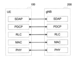
- FIG. 2 is a diagram showing the configuration of a protocol stack of a user plane wireless interface that handles data.
- FIG. 2 is a diagram showing the configuration of a protocol stack of a control plane radio interface that handles signaling (control signals).
- FIG. 2 is a diagram illustrating an example of an application scenario of the relay device (NCR device) according to the first embodiment.
- FIG. 2 is a diagram illustrating an example of an application scenario of the relay device (NCR device) according to the first embodiment.
- FIG. 3 is a diagram illustrating an example of a method of controlling a relay device (NCR device) according to the first embodiment.
- FIG. 1 is a diagram showing an example of a configuration of a protocol stack in a mobile communication system having a relay device (NCR device) according to a first embodiment
- FIG. 1 is a diagram illustrating a configuration example of a relay device (NCR device) according to a first embodiment
- FIG. It is a diagram showing an example of the configuration of a base station (gNB) according to an embodiment.
- FIG. 2 is a diagram showing an example of downlink signaling from a base station (gNB) to a control terminal (NCR-MT) according to the first embodiment.
- FIG. 2 is a diagram showing an example of uplink signaling from a control terminal (NCR-MT) to a base station (gNB) according to the first embodiment.
- FIG. 2 is a diagram showing an example of an overall operation sequence of the mobile communication system according to the first embodiment.
- FIG. 3 is a diagram for explaining beam sweeping according to the first embodiment.
- FIG. 2 is a diagram for explaining carrier aggregation (CA).
- FIG. 2 is a diagram for explaining dual connectivity (DC).
- FIG. 3 is a diagram illustrating a configuration example when CA is set in an NCR device (NCR-MT).
- NCR-MT NCR device
- FIG. 3 is a diagram illustrating a configuration example when setting a DC to an NCR device (NCR-MT).
- FIG. 3 is a diagram illustrating a first operation example in which multiple serving cells by CA according to the first embodiment are used in the NCR device.
- FIG. 3 is a diagram illustrating a first operation example in which multiple serving cells by the DC according to the first embodiment are used in the NCR device. It is a figure for explaining sCellDeactivationTimer.
- FIG. 7 is a diagram illustrating a third operation example in which multiple serving cells according to the first embodiment are used in the NCR device. It is a figure which shows the 4th example of operation which uses the multiple serving cell based on 1st Embodiment for an NCR apparatus.
- FIG. 3 is a diagram illustrating a first operation example regarding failure handling of the NCR device according to the first embodiment.
- FIG. 7 is a diagram illustrating a second operation example regarding failure handling of the NCR device according to the first embodiment.
- FIG. 7 is a diagram illustrating a third operation example regarding failure handling of the NCR device according to the first embodiment.
- FIG. 7 is a diagram for explaining a relay device according to a second embodiment.
- FIG. 7 is a diagram for explaining a relay device according to a second embodiment.
- FIG. 7 is a diagram for explaining operations according to other embodiments.
- an object of the present disclosure is to enable appropriate control of a relay device that performs relay transmission between a base station and a user device.
- the relay device according to the first embodiment is a repeater device that can be controlled from a network.
- FIG. 1 is a diagram showing the configuration of a mobile communication system according to the first embodiment.
- the mobile communication system 1 complies with the 5th Generation System (5GS) of the 3rd Generation Partnership Project (3GPP) (registered trademark, same hereinafter) standard.
- 5GS will be described as an example below
- an LTE (Long Term Evolution) system may be applied at least partially to the mobile communication system.
- a sixth generation (6G) system may be applied at least in part to the mobile communication system.
- the mobile communication system 1 includes a user equipment (UE) 100, a 5G radio access network (NG-RAN) 10, and a 5G core network (5GC). work) 20 and have Below, the NG-RAN 10 may be simply referred to as RAN 10. Further, the 5GC 20 may be simply referred to as the core network (CN) 20.
- UE user equipment
- NG-RAN 5G radio access network
- 5GC 5G core network
- the UE 100 is a mobile wireless communication device.
- the UE 100 may be any device as long as it is used by a user.
- the UE 100 may be a mobile phone terminal (including a smartphone) and/or a tablet terminal, a notebook PC, a communication module (including a communication card or a chipset), a sensor or a device provided in the sensor, a vehicle or a device provided in the vehicle ( Vehicle UE), a flying object, or a device installed on a flying object (Aerial UE).
- the NG-RAN 10 includes a base station (called “gNB” in the 5G system) 200.
- gNB200 is mutually connected via the Xn interface which is an interface between base stations.
- gNB200 manages one or more cells.
- the gNB 200 performs wireless communication with the UE 100 that has established a connection with its own cell.
- the gNB 200 has a radio resource management (RRM) function, a routing function for user data (hereinafter simply referred to as "data”), a measurement control function for mobility control/scheduling, and the like.
- RRM radio resource management
- Cell is a term used to indicate the smallest unit of wireless communication area.
- Cell is also used as a term indicating a function or resource for performing wireless communication with the UE 100.
- One cell belongs to one carrier frequency (hereinafter simply referred to as "frequency").
- the gNB 200 may be functionally divided into a central unit (CU) and a distributed unit (DU).
- CU controls DU.
- the CU is a unit that includes upper layers included in a protocol stack described below, such as an RRC layer, an SDAP layer, and a PDCP layer.
- the CU is connected to the core network via the NG interface, which is a backhaul interface.
- the CU is connected to adjacent base stations via an Xn interface, which is an interface between base stations.
- DUs form cells.
- the DU 202 is a unit that includes lower layers included in a protocol stack described below, such as an RLC layer, a MAC layer, and a PHY layer.
- the DU is connected to the CU via the F1 interface, which is a fronthaul interface.
- the gNB can also be connected to EPC (Evolved Packet Core), which is the core network of LTE.
- EPC Evolved Packet Core
- LTE base stations can also connect to 5GC.
- An LTE base station and a gNB can also be connected via an inter-base station interface.
- 5GC20 includes an AMF (Access and Mobility Management Function) and a UPF (User Plane Function) 300.
- the AMF performs various mobility controls for the UE 100.
- AMF manages the mobility of UE 100 by communicating with UE 100 using NAS (Non-Access Stratum) signaling.
- the UPF controls data transfer.
- AMF and UPF are connected to gNB 200 via an NG interface that is a base station-core network interface.
- FIG. 2 is a diagram showing the configuration of a protocol stack of a user plane wireless interface that handles data.
- the user plane radio interface protocols include the physical (PHY) layer, MAC (Medium Access Control) layer, RLC (Radio Link Control) layer, and PDCP (Packet Data Convergence Protocol). col) layer and SDAP (Service Data Adaptation Protocol) It has a layer.
- PHY physical
- MAC Medium Access Control
- RLC Radio Link Control
- PDCP Packet Data Convergence Protocol
- col Packet Data Convergence Protocol
- SDAP Service Data Adaptation Protocol
- the PHY layer performs encoding/decoding, modulation/demodulation, antenna mapping/demapping, and resource mapping/demapping. Data and control information are transmitted between the PHY layer of the UE 100 and the PHY layer of the gNB 200 via a physical channel.
- the PHY layer of the UE 100 receives downlink control information (DCI) transmitted from the gNB 200 on the physical downlink control channel (PDCCH).
- DCI downlink control information
- the UE 100 performs blind decoding of the PDCCH using a radio network temporary identifier (RNTI), and acquires the successfully decoded DCI as the DCI addressed to its own UE.
- RNTI radio network temporary identifier
- a CRC parity bit scrambled by the RNTI is added to the DCI transmitted from the gNB 200.
- SSB Synchronization Signal/PBCH block
- SSB consists of four consecutive OFDM (Orthogonal Frequency Division Multiplex) symbols, including a primary synchronization signal (PSS), a secondary synchronization signal (SSS), a physical broadcast channel (PBCH)/master information block (MIB), and , PBCH demodulation reference signals (DMRS) are arranged.
- PSS primary synchronization signal
- SSS secondary synchronization signal
- PBCH physical broadcast channel
- MIB master information block
- DMRS PBCH demodulation reference signals
- the bandwidth of SSB is, for example, a bandwidth of 240 consecutive subcarriers, or 20RB.
- the MAC layer performs data priority control, retransmission processing using Hybrid ARQ (HARQ: Hybrid Automatic Repeat reQuest), random access procedure, etc.
- Data and control information are transmitted between the MAC layer of UE 100 and the MAC layer of gNB 200 via a transport channel.
- the MAC layer of gNB 200 includes a scheduler. The scheduler determines uplink and downlink transport formats (transport block size, modulation and coding scheme (MCS)) and resource blocks to be allocated to the UE 100.
- MCS modulation and coding scheme
- the RLC layer uses the functions of the MAC layer and PHY layer to transmit data to the RLC layer on the receiving side. Data and control information are transmitted between the RLC layer of UE 100 and the RLC layer of gNB 200 via logical channels.
- the PDCP layer performs header compression/expansion, encryption/decryption, etc.
- the SDAP layer performs mapping between an IP flow, which is a unit in which the core network performs QoS (Quality of Service) control, and a radio bearer, which is a unit in which an AS (Access Stratum) performs QoS control. Note that if the RAN is connected to the EPC, the SDAP may not be provided.
- QoS Quality of Service
- AS Access Stratum
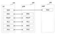
- FIG. 3 is a diagram showing the configuration of the protocol stack of the wireless interface of the control plane that handles signaling (control signals).
- the protocol stack of the wireless interface of the control plane includes an RRC (Radio Resource Control) layer and a NAS (Non-Access Stratum) layer instead of the SDAP layer shown in FIG. 2.
- RRC Radio Resource Control
- NAS Non-Access Stratum
- RRC signaling for various settings is transmitted between the RRC layer of the UE 100 and the RRC layer of the gNB 200.
- the RRC layer controls logical, transport and physical channels according to the establishment, re-establishment and release of radio bearers.
- RRC connection connection between the RRC of the UE 100 and the RRC of the gNB 200
- the UE 100 is in an RRC connected state.
- RRC connection no connection between the RRC of the UE 100 and the RRC of the gNB 200
- the UE 100 is in an RRC idle state.
- the connection between the RRC of the UE 100 and the RRC of the gNB 200 is suspended, the UE 100 is in an RRC inactive state.
- the NAS layer located above the RRC layer performs session management, mobility management, etc.
- NAS signaling is transmitted between the NAS layer of the UE 100 and the NAS layer of the AMF 300A.
- the UE 100 has an application layer and the like in addition to the wireless interface protocol.
- a layer lower than the NAS layer is called an AS layer.
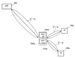
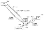
- FIGS. 4 and 5 are diagrams showing an example of an application scenario of the NCR device according to the first embodiment.
- 5G/NR is capable of wideband transmission using a high frequency band. Since radio signals in high frequency bands such as millimeter wave bands or terahertz wave bands have high straightness, reducing the coverage of the gNB 200 becomes an issue.
- the UE 100 may be located outside the coverage area of the gNB 200, for example, outside the area where wireless signals can be directly received from the gNB 200.
- a shield may exist between the gNB 200 and the UE 100, and the UE 100 may be unable to communicate within line of sight with the gNB 200.
- a mobile communication system uses a repeater device (500A), which is a type of relay device that relays wireless signals between the gNB 200 and the UE 100, and which can be controlled from a network. 1.
- a repeater device will be referred to as an NCR (Network-Controlled Repeater) device.
- NCR Network-Controlled Repeater
- Such a repeater device may be referred to as a smart repeater device.
- the NCR device 500A amplifies a wireless signal (radio wave) received from the gNB 200 and transmits it by directional transmission. Specifically, the NCR device 500A receives a wireless signal transmitted by the gNB 200 by beamforming. Then, the NCR device 500A amplifies the received radio signal without demodulating or modulating it, and transmits the amplified radio signal by directional transmission.
- the NCR device 500A may transmit a wireless signal with fixed directivity (beam).
- the NCR device 500A may transmit wireless signals using a variable (adaptive) directional beam. Thereby, the coverage of gNB 200 can be efficiently expanded.
- the NCR device 500A is applied to downlink communication from the gNB 200 to the UE 100, but the NCR device 500A can also be applied to uplink communication from the UE 100 to the gNB 200.
- a new UE (hereinafter referred to as "NCR-MT (Mobile termination)”) 520A which is a type of control terminal for controlling the NCR device 500A. That is, the NCR device 500A is a type of repeater that relays a wireless signal transmitted between the gNB 200 and the UE 100, and specifically changes the propagation state of the wireless signal without demodulating or modulating the wireless signal. It has an NCR-Fwd (Forward) 510A and an NCR-MT 520A that performs wireless communication with the gNB 200 and controls the NCR-Fwd 510A.
- NCR-MT Mobile termination
- the NCR-MT 520A controls the NCR device 500A in cooperation with the gNB 200 by establishing a wireless connection with the gNB 200 and performing wireless communication with the gNB 200. Thereby, efficient coverage expansion can be achieved using the NCR device 500A.
- NCR-MT520A controls NCR device 500A according to control from gNB200.
- the NCR-MT520A may be configured separately from the NCR-Fwd510A.
- the NCR-MT520A may be located near the NCR-Fwd510A and may be electrically connected to the NCR-Fwd510A.
- NCR-MT520A may be connected to NCR-Fwd510A by wire or wirelessly.
- the NCR-MT520A may be configured integrally with the NCR-Fwd510A.
- the NCR-MT 520A and the NCR-Fwd 510A may be fixedly installed, for example, at the coverage edge (cell edge) of the gNB 200, or on the wall or window of some building.
- the NCR-MT 520A and the NCR-Fwd 510A may be installed in, for example, a vehicle and may be movable. Further, one NCR-MT 520A may control a plurality of NCR-Fwds 510A.
- the NCR device 500A (NCR-Fwd 510A) dynamically or quasi-statically changes the beam it transmits or receives.
- the NCR-Fwd 510A forms a beam toward each of the UE 100a and UE 100b.
- the NCR-Fwd 510A may form a beam toward the gNB 200.
- the NCR-Fwd 510A transmits a radio signal received from the gNB 200 toward the UE 100a by beamforming, and/or beamforms a radio signal received from the UE 100a toward the gNB 200. Send by.
- NCR-Fwd 510A transmits a radio signal received from gNB 200 to UE 100b by beamforming, and/or transmits a radio signal received from UE 100b to gNB 200 by beamforming, in the communication resources between gNB 200 and UE 100b. do. Instead of or in addition to beam formation, the NCR-Fwd 510A performs null formation (towards a UE 100 (not shown) that is not a communication partner and/or a neighboring gNB 200 (not shown)) for interference suppression. So-called null steering) may also be used.
- FIG. 6 is a diagram illustrating an example of a method of controlling the NCR device 500A according to the first embodiment.
- the NCR-Fwd 510A relays a radio signal (also referred to as a "UE signal") between the gNB 200 and the UE 100.
- the UE signal includes an uplink signal (also referred to as a "UE-UL signal”) transmitted from the UE 100 to the gNB 200, and a downlink signal (also referred to as a "UE-DL signal”) transmitted from the gNB 200 to the UE 100.
- UE-UL signal uplink signal
- UE-DL signal downlink signal
- the NCR-Fwd 510A relays the UE-UL signal from the UE 100 to the gNB 200, and also relays the UE-DL signal from the gNB 200 to the UE 100.
- the wireless link between the NCR-Fwd 510A and the UE 100 is also referred to as an "access link.”
- the wireless link between the NCR-Fwd 510A and the gNB 200 is also referred to as a "backhaul link.”
- the NCR-MT 520A transmits and receives a wireless signal (herein referred to as "NCR-MT signal") with the gNB 200.
- the NCR-MT signal includes an uplink signal (referred to as “NCR-MT-UL signal”) transmitted from NCR-MT520A to gNB200 and a downlink signal (referred to as "NCR-MT-UL signal") transmitted from gNB200 to NCR-MT520A. DL signal).
- the NCR-MT-UL signal includes signaling for controlling the NCR device 500A.
- the wireless link between NCR-MT520A and gNB200 is also referred to as a "control link.”
- gNB200 directs the beam to NCR-MT520A based on the NCR-MT-UL signal from NCR-MT520A. Since the NCR device 500A is co-located with the NCR-MT520A, if the backhaul link and control link have the same frequency, when the gNB 200 directs the beam to the NCR-MT520A, the resulting The beam will also be directed to NCR-Fwd510A. gNB 200 transmits the NCR-MT-DL signal and UE-DL signal using the beam. NCR-MT520A receives the NCR-MT-DL signal.
- the NCR-Fwd510A and the NCR-MT520A have the function of transmitting/receiving or relaying the UE signal and/or the NCR-MT signal (for example, the antenna ) may be integrated.
- the beam includes a transmission beam and/or a reception beam. Beam is a general term for controlled transmission and/or reception to maximize the power of transmitted waves and/or received waves in a specific direction by adjusting/adapting antenna weights and the like.
- FIG. 7 is a diagram showing a configuration example of a protocol stack in the mobile communication system 1 having the NCR device 500A according to the first embodiment.
- NCR-Fwd510A relays wireless signals transmitted and received between gNB200 and UE100.
- the NCR-Fwd 510A has an RF (Radio Frequency) function to amplify and relay received radio signals, and performs directional transmission by beamforming (eg, analog beamforming).
- RF Radio Frequency
- the NCR-MT 520A has at least one layer (entity) of PHY, MAC, RRC, and F1-AP (Application Protocol).
- F1-AP is a type of fronthaul interface.
- the NCR-MT 520A exchanges downlink signaling and/or uplink signaling, which will be described later, with the gNB 200 using at least one of PHY, MAC, RRC, and F1-AP. If the NCR-MT 520A is a type or part of a base station, the NCR-MT 520A may communicate with the gNB 200 through an Xn AP (Xn-AP) that is an interface between base stations.
- Xn-AP Xn AP
- FIG. 8 is a diagram showing a configuration example of the NCR device 500A, which is the relay device according to the first embodiment.
- the NCR device 500A includes an NCR-Fwd 510A, an NCR-MT 520A, and an interface 530.
- the NCR-Fwd 510A includes a wireless unit 511A and an NCR control section 512A.
- the wireless unit 511A includes an antenna section 511a including a plurality of antennas (multiple antenna elements), an RF circuit 511b including an amplifier, and a directivity control section 511c that controls the directivity of the antenna section 511a.
- the RF circuit 511b amplifies and relays (transmits) radio signals transmitted and received by the antenna section 511a.
- the RF circuit 511b may convert a radio signal, which is an analog signal, into a digital signal, and after digital signal processing, convert it back into an analog signal.
- the directivity control unit 511c may perform analog beamforming using analog signal processing.
- the directivity control unit 511c may perform digital beamforming using digital signal processing.
- the directivity control unit 511c may perform analog and digital hybrid beamforming.
- the NCR control section 512A controls the wireless unit 511A according to the control signal from the NCR-MT 520A.
- NCR control unit 512A may include at least one processor.
- the NCR control unit 512A may output information regarding the capabilities of the NCR device 500A to the NCR-MT 520A.
- the NCR-MT 520A includes a receiving section 521, a transmitting section 522, and a control section 523.
- the receiving unit 521 performs various types of reception under the control of the control unit 523.
- Receiving section 521 includes an antenna and a receiver.
- the receiver converts a radio signal (radio signal) received by the antenna into a baseband signal (received signal) and outputs the baseband signal (received signal) to the control unit 523.
- the transmitter 522 performs various types of transmission under the control of the controller 523.
- the transmitter 522 includes an antenna and a transmitter.
- the transmitter converts the baseband signal (transmission signal) output by the control unit 523 into a wireless signal and transmits it from the antenna.
- the control unit 523 performs various controls in the NCR-MT 520A.
- Control unit 523 includes at least one processor and at least one memory.
- the memory stores programs executed by the processor and information used in processing by the processor.
- the processor may include a baseband processor and a CPU (Central Processing Unit).
- the baseband processor performs modulation/demodulation, encoding/decoding, etc. of the baseband signal.
- the CPU executes programs stored in memory to perform various processes. Further, the control unit 523 executes functions of at least one layer of PHY, MAC, RRC, and F1-AP.
- the interface 530 electrically connects the NCR-Fwd 510A and the NCR-MT 520A.
- the control unit 523 of the NCR-MT 520A controls the NCR-Fwd 510A via the interface 530.
- the receiving unit 521 of the NCR-MT 520A receives signaling (downlink signaling) used to control the NCR device 500A from the gNB 200 via wireless communication.
- the control unit 523 of the NCR-MT 520A controls the NCR device 500A based on the signaling. This allows the gNB 200 to control the NCR-Fwd 510A via the NCR-MT 520A.
- control unit 523 of the NCR-MT 520A may transmit NCR capability information indicating the capability of the NCR device 500A to the gNB 200 via wireless communication.
- NCR capability information is an example of uplink signaling from NCR-MT 520A to gNB 200. This allows the gNB 200 to grasp the capabilities of the NCR device 500A.
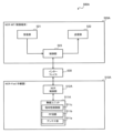
- FIG. 9 is a diagram showing a configuration example of the gNB 200 according to the first embodiment.
- gNB 200 includes a transmitting section 210, a receiving section 220, a control section 230, and a backhaul communication section 240.
- the transmitter 210 performs various transmissions under the control of the controller 230.
- Transmitter 210 includes an antenna and a transmitter.
- the transmitter converts the baseband signal (transmission signal) output by the control unit 230 into a wireless signal and transmits it from the antenna.
- the receiving unit 220 performs various types of reception under the control of the control unit 230.
- Receiving section 220 includes an antenna and a receiver.
- the receiver converts the radio signal received by the antenna into a baseband signal (received signal) and outputs it to the control unit 230.
- the transmitter 210 and the receiver 220 may be capable of beam forming using multiple antennas.
- Control unit 230 performs various controls in the gNB 200.
- Control unit 230 includes at least one processor and at least one memory.
- the memory stores programs executed by the processor and information used in processing by the processor.
- the processor may include a baseband processor and a CPU.
- the baseband processor performs modulation/demodulation, encoding/decoding, etc. of the baseband signal.
- the CPU executes programs stored in memory to perform various processes.
- the backhaul communication unit 240 is connected to adjacent base stations via an inter-base station interface.
- Backhaul communication unit 240 is connected to AMF/UPF 300 via a base station-core network interface.
- the gNB may be configured (that is, functionally divided) of a CU (Central Unit) and a DU (Distributed Unit), and the two units may be connected by an F1 interface.
- the transmitting unit 210 of the gNB 200 transmits signaling (downlink signaling) used for controlling the NCR-Fwd 510A to the NCR-MT 520A by wireless communication. This allows the gNB 200 to control the NCR device 500A via the NCR-MT 520A.
- the receiving unit 220 of the gNB 200 may receive NCR capability information indicating the capability of the NCR device 500A from the NCR-MT 520A via wireless communication.
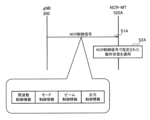
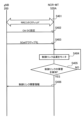
- FIG. 10 is a diagram showing an example of downlink signaling from the gNB 200 to the NCR-MT 520A according to the first embodiment.
- the gNB 200 transmits downlink signaling to the NCR-MT 520A.
- the downlink signaling may be an RRC message that is RRC layer (ie, layer 3) signaling.
- the downlink signaling may be MAC CE (Control Element), which is MAC layer (namely, layer 2) signaling.
- the downlink signaling may be downlink control information (DCI) that is PHY layer (ie, layer 1) signaling.
- DCI downlink control information
- PHY layer ie, layer 1 signaling.
- Downlink signaling may be UE-specific signaling.
- the downlink signaling may be broadcast signaling.
- the downlink signaling may be a fronthaul message (eg, an F1-AP message). If the NCR-MT 520A is a type or part of a base station, the NCR-MT 520A may communicate with the gNB 200 through an Xn AP (Xn-AP) that is an interface between base stations.
- Xn-AP Xn
- the gNB 200 transmits an NCR control signal specifying the operating state of the NCR device 500A as downlink signaling to the NCR-MT 520A that has established a wireless connection with the gNB 200 (step S1A).
- the NCR control signal specifying the operating state of the NCR device 500A may be MAC CE, which is MAC layer (layer 2) signaling, or DCI, which is PHY layer (layer 1) signaling.
- the NCR control signal may be included in an RRC Reconfiguration message, which is a type of UE-specific RRC message, and transmitted to the NCR-MT 520A.
- Downlink signaling may be a message of a layer higher than the RRC layer (for example, NCR application).
- Downlink signaling may be such that a message in a layer higher than the RRC layer is encapsulated in a message in a layer below the RRC layer and then transmitted.
- the NCR-MT 520A (transmission unit 522) may transmit a response message to downlink signaling from the gNB 200 on the uplink.
- the response message may be transmitted in response to the NCR device 500A completing the configuration specified in the downlink signaling or receiving the configuration.
- the NCR control signal may be referred to as Side Control Information.
- the NCR control signal may include frequency control information that specifies the center frequency of a wireless signal (for example, a component carrier) to be relayed by the NCR-Fwd 510A.
- the NCR-MT 520A controls the NCR-Fwd 510A to relay the radio signal of the center frequency indicated by the frequency control information ( Step S2A).
- the NCR control signal may include a plurality of frequency control information specifying mutually different center frequencies. Since the NCR control signal includes frequency control information, the gNB 200 can specify the center frequency of the wireless signal to be relayed by the NCR-Fwd 510A via the NCR-MT 520A.
- the NCR control signal may include mode control information that specifies the operation mode of the NCR-Fwd 510A.
- Mode control information may be associated with frequency control information (center frequency).
- the operating modes are a mode in which the NCR-Fwd510A performs omnidirectional transmission and/or reception, a mode in which the NCR-Fwd510A performs fixed directional transmission and/or reception, and a mode in which the NCR-Fwd510A performs variable directional beam.
- a mode in which the NCR-Fwd 510A performs MIMO (Multiple Input Multiple Output) relay transmission may be used.
- MIMO Multiple Input Multiple Output
- the operation mode may be either a beamforming mode (that is, a mode that emphasizes desired wave improvement) or a null steering mode (that is, a mode that emphasizes interference wave suppression).
- the NCR-MT 520A controls the NCR-Fwd 510A to operate in the operation mode indicated by the mode control information (step S2A). Since the NCR control signal includes mode control information, the gNB 200 can specify the operation mode of the NCR-Fwd 510A via the NCR-MT 520A.
- the mode in which the NCR device 500A performs omnidirectional transmission and/or reception is a mode in which the NCR-Fwd 510A performs relay in all directions, and may be referred to as omni mode.
- the mode in which the NCR-Fwd 510A performs fixed directional transmission and/or reception may be a directional mode realized by one directional antenna.
- the mode may be a beamforming mode realized by applying fixed phase/amplitude control (antenna weight control) to a plurality of antennas. Any of these modes may be designated (set) from the gNB 200 to the NCR-MT 520A.
- the mode in which the NCR-Fwd 510A performs transmission and/or reception using a variable directional beam may be a mode in which analog beamforming is performed.
- the mode may be a mode in which digital beamforming is performed.
- the mode may be a mode in which hybrid beamforming is performed.
- the mode may be a mode that forms an adaptive beam specific to the UE 100. Any of these modes may be designated (set) from the gNB 200 to the NCR-MT 520A. Note that in the beamforming operation mode, beam control information, which will be described later, may be provided from the gNB 200 to the NCR-MT 520A.
- the mode in which the NCR device 500A performs MIMO relay transmission may be a mode in which SU (Single-User) spatial multiplexing is performed.
- the mode may be a mode that performs MU (Multi-User) spatial multiplexing.
- the mode may be a mode that performs transmission diversity. Any of these modes may be designated (set) from the gNB 200 to the NCR-MT 520A.
- the operation modes may include a mode in which relay transmission by the NCR-Fwd 510A is turned on (activated) and a mode in which relay transmission by the NCR-Fwd 510A is turned off (deactivated). Any of these modes may be designated (set) from the gNB 200 to the NCR-MT 520A by an NCR control signal.
- the NCR control signal may include beam control information that specifies the transmission direction, transmission weight, or beam pattern when the NCR-Fwd 510A performs directional transmission.
- the beam control information may be associated with frequency control information (center frequency).
- the beam control information may include a PMI (Precoding Matrix Indicator).
- the beam control information may include beam forming angle information.
- the NCR-MT 520A controls the NCR-Fwd 510A to form a transmission directivity (beam) indicated by the beam control information (step S2A). Since the NCR control signal includes beam control information, the gNB 200 can control the transmission directivity of the NCR device 500A via the NCR-MT 520A.
- the NCR control signal may include output control information that specifies the degree to which the NCR-Fwd 510A amplifies the wireless signal (amplification gain) or the transmission power.
- the output control information may be information indicating a difference value (ie, relative value) between the current amplification gain or transmission power and the target amplification gain or transmission power. If the NCR control signal received from the gNB 200 includes output control information, the NCR-MT 520A (control unit 523) controls the NCR-Fwd 510A to change to the amplification gain or transmission power indicated by the output control information (step S2A). ).
- the output control information may be associated with frequency control information (center frequency).
- the output control information may be information specifying any one of the amplifier gain, beamforming gain, and antenna gain of the NCR-Fwd 510A.
- the output control information may be information specifying the transmission power of the NCR-Fwd 510A.
- the gNB 200 may transmit an NCR control signal to the NCR-MT 520A for each NCR-Fwd 510A.
- the NCR control signal may include the identifier (NCR identifier) of the corresponding NCR-Fwd 510A.
- the NCR-MT 520A (control unit 523) that controls the plurality of NCR-Fwds 510A determines the NCR-Fwd 510A to which the NCR control signal is applied based on the NCR identifier included in the NCR control signal received from the gNB 200. Note that the NCR identifier may be transmitted from the NCR-MT 520A to the gNB 200 together with the NCR control signal even when the NCR-MT 520A controls only one NCR-Fwd 510A.
- the NCR-MT 520A controls the NCR-Fwd 510A based on the NCR control signal from the gNB 200. This allows the gNB 200 to control the NCR-Fwd 510A via the NCR-MT 520A.
- FIG. 11 is a diagram showing an example of uplink signaling from the NCR-MT 520A to the gNB 200 according to the first embodiment.
- the NCR-MT 520A (transmission unit 210) transmits uplink signaling to the gNB 200.
- the uplink signaling may be an RRC message that is RRC layer signaling.
- the uplink signaling may be MAC CE, which is MAC layer signaling.
- the uplink signaling may be uplink control information (UCI) that is PHY layer signaling.
- the uplink signaling may be a fronthaul message (eg, an F1-AP message).
- the uplink signaling may be an inter-base station message (eg, an Xn-AP message).
- Uplink signaling may be a message of a layer higher than the RRC layer (for example, NCR application).
- Uplink signaling may encapsulate a message in a layer higher than the RRC layer with a message in a layer below the RRC layer, and then transmit the message. That is, uplink signaling stores upper layer messages in lower layer containers.
- the gNB 200 transmission unit 210) may transmit a response message to uplink signaling from the NCR-MT 520A on the downlink, and the NCR-MT 520A (reception unit 521) may receive the response message.
- the NCR-MT 520A (transmission unit 522) that has established a wireless connection with the gNB 200 transmits NCR capability information indicating the capability of the NCR device 500A to the gNB 200 as uplink signaling (step S5A).
- the NCR-MT 520A (transmission unit 522) may include NCR capability information in a UE Capability message or a UE Assistant Information message, which is a type of RRC message, and transmit the message to the gNB 200.
- the NCR-MT 520A (transmission unit 522) may transmit NCR capability information (NCR capability information and/or operating state information) to the gNB 200 in response to a request or inquiry from the gNB 200.
- the NCR capability information may include corresponding frequency information indicating the frequency supported by the NCR-Fwd 510A.
- the corresponding frequency information may be a numerical value or an index indicating the center frequency of the frequency corresponding to the NCR-Fwd 510A.
- the corresponding frequency information may be a numerical value or an index indicating the range of frequencies supported by the NCR-Fwd 510A. If the NCR capability information received from the NCR-MT 520A includes corresponding frequency information, the gNB 200 (control unit 230) can grasp the frequency supported by the NCR-Fwd 510A based on the corresponding frequency information. Then, the gNB 200 (control unit 230) may set the center frequency of the wireless signal targeted by the NCR device 500A within the frequency range supported by the NCR-Fwd 510A.
- the NCR capability information may include mode capability information regarding operation modes that can be supported by the NCR-Fwd 510A or switching between operation modes.
- the operating modes are a mode in which the NCR-Fwd510A performs omnidirectional transmission and/or reception, a mode in which the NCR-Fwd510A performs fixed directional transmission and/or reception, and a mode in which the NCR-Fwd510A performs fixed directional transmission and/or reception.
- the mode may be at least one of a mode in which transmission and/or reception is performed using a variable directional beam, and a mode in which the NCR-Fwd 510A performs MIMO (Multiple Input Multiple Output) relay transmission.
- MIMO Multiple Input Multiple Output
- the operation mode may be either a beamforming mode (that is, a mode that emphasizes desired wave improvement) or a null steering mode (that is, a mode that emphasizes interference wave suppression).
- the mode capability information may be information indicating which of these operation modes the NCR-Fwd 510A is compatible with.
- the mode capability information may be information indicating which of these operating modes can be switched between. If the NCR capability information received from the NCR-MT 520A includes mode capability information, the gNB 200 (control unit 230) can grasp the operation mode and mode switching supported by the NCR-Fwd 510A based on the mode capability information. Then, the gNB 200 (control unit 230) may set the operation mode of the NCR-Fwd 510A within the grasped operation mode and mode switching range.
- the NCR capability information may include beam capability information indicating a beam variable range, beam variable resolution, or variable pattern number when the NCR-Fwd 510A performs transmission and/or reception using a variable directional beam.
- the beam capability information may be, for example, information indicating a variable range of the beam angle (for example, controllable from 30° to 90°) with respect to the horizontal or vertical direction.
- the beam capability information may be information indicating an absolute angle.
- the beam capability information may be expressed by a direction and/or an elevation angle in which the beam is directed.
- the beam capability information may be information indicating an angle change for each variable step (for example, horizontal 5°/step, vertical 10°/step).
- the beam capability information may be information indicating a variable number of steps (for example, 10 horizontal steps, 20 vertical steps).
- the beam capability information may be information indicating the number of variable beam patterns in the NCR-Fwd 510A (for example, a total of 10 patterns of beam patterns 1 to 10). If the NCR capability information received from the NCR-MT 520A includes beam capability information, the gNB 200 (control unit 230) can grasp the beam angle change or beam pattern that the NCR-Fwd 510A can handle based on the beam capability information. Then, the gNB 200 (control unit 230) may set the beam of the NCR-Fwd 510A within the range of the determined beam angle change or beam pattern. These beam capability information may be null capability information. In the case of null capability information, these beam capability information indicate the null control capability when performing null steering.
- the NCR capability information may include control delay information indicating the control delay time in the NCR device 500A.
- the control delay information includes control according to the NCR control signal (change of operation mode and/or change of beam ) is information indicating the delay time (for example, 1 ms, 10 ms, etc.) until completion. If the NCR capability information received from the NCR-MT 520A includes control delay information, the gNB 200 (control unit 230) can grasp the control delay time in the NCR-Fwd 510A based on the control delay information.
- the NCR capability information may include amplification characteristic information regarding the amplification characteristic or output power characteristic of the wireless signal in the NCR-Fwd 510A.
- the amplification characteristic information may be information indicating the amplifier gain (dB), beamforming gain (dB), and antenna gain (dBi) of the NCR-Fwd510A.
- the amplification characteristic information may be information indicating a variable amplification range (for example, 0 dB to 60 dB) in the NCR-Fwd 510A.
- the amplification characteristic information may be information indicating the number of amplification steps (for example, 10 steps) that the NCR-Fwd 510A can change, or the amplification degree for each variable step (for example, 10 dB/step).
- the amplification characteristic information may be information indicating a variable range (for example, 0 dBm to 30 dBm) of the output power of the NCR-Fwd 510A.
- the amplification characteristic information may be information indicating the number of output power steps that the NCR-Fwd510A can change (for example, 10 steps) or the output power for each variable step (for example, 10 dBm/step or 10 dB/step). good.
- the NCR capability information may include location information indicating the installation location of the NCR device 500A.
- the location information may include one or more of latitude, longitude, and altitude.
- the position information may include information indicating the distance and/or installation angle of the NCR device 500A with respect to the gNB 200.
- the installation angle may be a relative angle with respect to the gNB 200, or may be a relative angle with respect to, for example, north, vertically, or horizontally.
- the installation position may be position information of a place where the antenna section 511a of the NCR-Fwd 510A is installed.
- the NCR capability information may include antenna information indicating the number of antennas that the NCR-Fwd 510A has.
- the antenna information may be information indicating the number of antenna ports that the NCR-Fwd 510A has.
- the antenna information may be information indicating the degree of freedom of directivity control (beam or null formation).
- the degree of freedom indicates how many beams can be formed (controlled), and is usually "(number of antennas) - 1". For example, in the case of two antennas, the degree of freedom is one. In the case of two antennas, a figure-eight beam pattern is formed, but since the directivity can only be controlled in one direction, the degree of freedom is one.
- the NCR-MT 520A may transmit NCR capability information to the gNB 200 for each NCR-Fwd 510A.
- the NCR capability information may include the number of NCR-Fwds 510A and/or the identifier (NCR identifier) of the corresponding NCR-Fwds 510A.
- the NCR-MT520A controls a plurality of NCR-Fwd510A
- the NCR-MT520A indicates at least one of the identifier of each of the plurality of NCR-Fwd510A and the number of the plurality of NCR-Fwd510A. You may also send information.
- the NCR identifier may be transmitted from the NCR-MT 520A to the gNB 200 together with the NCR capability information even if the NCR-MT 520A controls only one NCR-Fwd 510A.
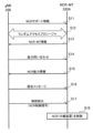
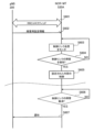
- FIG. 12 is a diagram showing an example of the overall operation sequence of the mobile communication system 1 according to the first embodiment.
- sequence diagrams referred to in the following embodiments non-essential steps are shown with broken lines.
- NCR in FIG. 12 may be replaced with "RIS”.
- the gNB 200 (transmission unit 210) broadcasts NCR support information indicating that the gNB 200 supports the NCR-MT 520A.
- the gNB 200 (transmitter 210) broadcasts a system information block (SIB) that includes NCR support information.
- SIB system information block
- NCR support information may be information indicating that NCR-MT520A is accessible.
- the gNB 200 (transmission unit 210) may broadcast NCR non-support information indicating that the gNB 200 does not support the NCR-MT 520A.
- the NCR non-support information may be information indicating that the NCR-MT 520A is inaccessible.
- the NCR-MT 520A may be in an RRC idle state or an RRC inactive state.
- the NCR-MT520A (control unit 523), which has not established a wireless connection with the gNB200, determines that access to the gNB200 is permitted in response to receiving the NCR support information from the gNB200, and establishes a wireless connection with the gNB200. An access operation may be performed to establish the .
- the NCR-MT 520A (control unit 523) may perform cell reselection by regarding the gNB 200 (cell) to which access is permitted as having the highest priority.
- the NCR-MT 520A (control unit 523) that has not established a wireless connection with the gNB 200 It may be determined that access (connection establishment) is not possible. Thereby, the NCR-MT 520A can establish a wireless connection only to the gNB 200 that can handle the NCR-MT 520A.
- the gNB 200 may broadcast access restriction information that restricts access from the UE 100.
- the NCR-MT 520A can also be regarded as an entity on the network side. Therefore, the NCR-MT 520A may ignore the access restriction information from the gNB 200. For example, when the NCR-MT520A (control unit 523) receives NCR support information from a gNB200, the NCR-MT520A (control unit 523) may perform an operation to establish a wireless connection with the gNB200 even if the gNB200 is broadcasting access restriction information. good.
- the NCR-MT 520A (control unit 523) does not need to execute (or may ignore) UAC (Unified Access Control).
- UAC Unified Access Control
- a special value may be used for one or both of AC/AI (Access Category/Access Identity) used in the UAC to indicate NCR-MT access.
- step S12 the NCR-MT 520A (control unit 523) starts a random access procedure for the gNB 200.
- the NCR-MT 520A transmission unit 522 transmits a random access preamble (Msg1) and an RRC message (Msg3) to the gNB 200.
- the NCR-MT 520A receiving unit 521) receives a random access response (Msg2) and an RRC message (Msg4) from the gNB 200.
- the NCR-MT 520A may transmit NCR-MT information indicating that the own UE is an NCR-MT to the gNB 200 when establishing a wireless connection with the gNB 200.
- the NCR-MT 520A includes NCR-MT information in a message for the random access procedure (for example, Msg1, Msg3, Msg5) and transmits the message to the gNB 200.
- the gNB 200 (control unit 230) recognizes that the accessed UE 100 is the NCR-MT 520A based on the NCR-MT information received from the NCR-MT 520A.
- the gNB 200 (control unit 230) can, for example, remove the NCR-MT 520A from the access restriction target (that is, accept access). Once the random access procedure is completed, the NCR-MT 520A transitions from the RRC idle state or RRC inactive state to the RRC connected state.
- step S14 the gNB 200 (transmission unit 522) transmits a capability inquiry message to the NCR-MT 520A, inquiring about the capabilities of the NCR-MT 520A.
- the NCR-MT 520A (receiving unit 521) receives the capability inquiry message.
- the NCR-MT 520A transmits a capability information message including NCR capability information to the gNB 200.
- the capability information message may be an RRC message, for example a UE Capability message.
- gNB 200 (receiving unit 220) receives the capability information message.
- the gNB 200 (control unit 230) grasps the capability of the NCR device 500A based on the received capability information message.
- the gNB 200 transmits a configuration message including various settings regarding the NCR device 500A to the NCR-MT 520A.
- the NCR-MT 520A receives the configuration message.
- the configuration message is a type of downlink signaling described above.
- the configuration message may be an RRC message, for example, an RRC Reconfiguration message.
- the gNB 200 transmits a control instruction specifying the operating state of the NCR-Fwd 510A to the NCR-MT 520A.
- the control instruction may be the above-mentioned NCR control signal (for example, L1/L2 signaling).
- the NCR-MT 520A (receiving unit 521) receives the control instruction.
- NCR-MT 520A (control unit 523) controls NCR-Fwd 510A according to control instructions.
- the NCR-MT 520A controls the NCR device 500A according to the above settings (and control instructions).
- the NCR-MT 520A may autonomously control the NCR device 500A without depending on control instructions from the gNB 200.
- the NCR-MT 520A may autonomously control the NCR device 500A based on the location of the UE 100 and/or information received by the NCR-MT 520A from the UE 100.
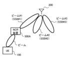
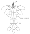
- FIG. 13 is a diagram for explaining beam sweeping according to the embodiment.
- the gNB 200 performs beam sweeping in which beams are sequentially switched and transmitted in different directions. At this time, the gNB 200 transmits a different SSB for each beam.
- the SSB is periodically transmitted from the gNB 200 into the cell as an SSB burst consisting of a plurality of SSBs. A plurality of SSBs within one SSB burst are each given an SSB index, which is an identifier.
- the SSBs are beamformed and transmitted in different directions.
- the NCR device 500A (NCR-MT 520A) reports to the gNB 200 during the random access channel (RACH) procedure which direction the beam received had good reception quality.
- RACH random access channel
- the NCR device 500A (NCR-MT 520A) transmits a random access preamble to the gNB 200 on a random access channel (RACH) occasion associated with an SSB index with good beam reception quality.
- RACH random access channel
- the gNB 200 can determine the optimum beam for the NCR device 500A (NCR-MT520A).
- SSB may be transmitted in the initial BWP (initial DL BWP).
- a dedicated BWP may be configured and activated on the NCR device 500A (NCR-MT520A).
- CSI-RS channel state information reference signal
- an example in which beam information for identifying a beam is an SSB index will be mainly described on the premise that there is a one-to-one relationship between a beam and an SSB (specifically, an SSB index).
- the beam may be associated with a CSI-RS.
- the beam information identifying the beam may be a CSI-RS index.
- the gNB 200 connects multiple serving cells to the NCR device 500A (NCR-MT520A) by carrier aggregation (CA) or dual connectivity (DC). ) can be set. Prior to explaining such operations, general CA and DC will be explained.
- CA carrier aggregation
- DC dual connectivity
- FIG. 14 is a diagram for explaining CA.
- CA multiple component carriers (CCs) corresponding to multiple serving cells are aggregated, and the UE 100 can receive or transmit simultaneously using multiple CCs.
- the plurality of CCs may be continuous in the frequency direction.
- the plurality of CCs may be discontinuous.
- the UE 100 has only one RRC connection with the network (for example, gNB 200).
- the network for example, gNB 200.
- one serving cell provides NAS mobility information
- RRC connection re-establishment/handover one serving cell provides security input.
- the one serving cell is called a primary cell (PCell).
- SCell secondary cell
- a set of serving cells can be formed. Therefore, the set of serving cells configured in the UE 100 is always composed of one PCell and one or more SCells. Reconfiguration, addition, and deletion of SCells can be performed by RRC.
- the primary cell is an MCG cell operating on the primary frequency in which the UE 100 performs an initial connection establishment procedure or initiates a connection re-establishment procedure.
- the UE 100 receives an RRCSetup message from a cell in the initial connection establishment procedure, the UE 100 considers the cell to be the primary cell.
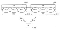
- FIG. 15 is a diagram for explaining DC.
- the UE 100 communicates with a master cell group (MCG) 201M managed by a master node (MN) 200M and a secondary cell group (SCG) 201S managed by a secondary node (SN) 200S.
- MCG master cell group
- SCG secondary cell group
- SN secondary node
- the MN 200M and SN 200S are connected to each other via a network interface (specifically, an inter-base station interface).
- the network interface may be an Xn interface or an X2 interface.
- the MN 200M may be referred to as a master base station
- the SN 200S may be referred to as a secondary base station.
- an example will be described in which both the MN 200M and the SN 200S are gNBs 200, but at least one of the MN 200M and the SN 200S may be an LTE base station (eNB).
- eNB LTE base station
- the DC is started when the MN 200M sends a predetermined message (for example, an SN Addition Request message) to the SN 200S, and the MN 200M sends an RRC Reconfiguration message to the UE 100.
- the UE 100 in the RRC connected state is allocated radio resources by the respective schedulers of the MN 200M and the SN 200S, and performs radio communication using the radio resources of the MN 200M and the radio resources of the SN 200S.
- the MN 200M may have a control plane connection with the core network.
- the MN 200M provides the main radio resources for the UE 100.
- MN200M manages MCG201M.
- MCG 201M is a group of serving cells associated with MN 200M.
- MCG201M has a primary cell (PCell) and optionally has one or more secondary cells (SCell).
- the SN 200S may not have a control plane connection with the core network.
- SN200S provides additional radio resources to UE100.
- SN200S manages SCG201S.
- the SCG 201S has a primary/secondary cell (PSCell), and optionally has one or more SCells. Note that the PCell of the MCG 201M and the PSCell of the SCG 201S are sometimes referred to as special cells (SpCell).
- FIG. 16 is a diagram illustrating a configuration example when CA is set in the NCR device 500A (NCR-MT 520A).
- control link ie, the wireless link between NCR-MT 520A and gNB 200
- backhaul link ie, the wireless link between NCR-Fwd 510A and gNB 200
- This frequency is also referred to as a "predetermined frequency.”
- channel conditions can be made uniform between the control link and the backhaul link, and the control of the NCR-Fwd 510A can be simplified.
- the gNB 200 grasps the channel state of the backhaul link and performs appropriate beamforming and link adaptation (determination of MCS, etc.) for the backhaul link. )It can be performed.
- the gNB 200 sets the cell C2 corresponding to the frequency of the radio signal (from another perspective, component carrier) relayed by the NCR device 500A to the NCR device 500A. (NCR-MT520A). This frequency is also referred to as "the operating frequency of NCR-Fwd510A.”
- the serving cell C2 is used for control links and backhaul links.
- NCR-MT 520A communicates with gNB 200 via a control link at layer 1 and/or layer 2 (L1/L2).
- the frequency of the serving cell C2 may be a frequency of a millimeter wave band (also referred to as "FR (Frequency Range) 2"). It is difficult to achieve stable wireless communication in such high frequency bands. Therefore, in the embodiment, by setting the serving cell C1, which has a frequency different from that of the serving cell C2, in the NCR device 500A (NCR-MT520A), it is possible to provide an RRC connection belonging to layer 3 (L3) on a different frequency. . This allows the control link and RRC connection to be separated.
- the serving cell C1 may have a frequency lower than the frequency of the serving cell C2, for example, a frequency in the Sub-6 band (also referred to as "FR1").
- serving cell C1 is a primary cell and serving cell C2 is a secondary cell. This makes it possible to stabilize the RRC connection of the NCR-MT520A while simplifying the control of the NCR-Fwd510A.
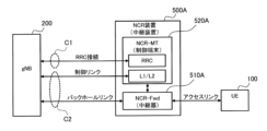
- FIG. 17 is a diagram illustrating a configuration example when setting the DC to the NCR device 500A (NCR-MT520A).
- serving cell C1 is provided in MN (gNB) 200M, and serving cell C2 is provided in SN (gNB) 200S.
- serving cell C1 is a primary cell belonging to MCG 201M of MN 200M.
- the serving cell C2 is a secondary cell belonging to the SCG 201S of the SN 200S.
- the NCR-Fwd 510A relays a radio signal of a predetermined frequency transmitted between the gNB 200 and the UE 100.
- NCR-MT520A performs wireless communication with gNB200 and controls NCR-Fwd510A.
- a plurality of serving cells including cell C1 corresponding to a predetermined frequency are set in NCR-MT 520A by gNB 200.
- cell C2 corresponding to the predetermined frequency is a secondary cell.
- the secondary cell may be a primary secondary cell (PSCell) in the DC.
- the secondary cell may be inactive (that is, not used for communication) at the time it is set.
- the NCR-MT 520A configured with a secondary cell may receive an activation instruction to activate the secondary cell from the gNB 200.
- the NCR-MT 520A may activate the operation of the NCR-Fwd 510A, that is, make it usable for relaying. This allows the operation of the NCR-Fwd 510A to be inactive while the secondary cell is inactive, thereby suppressing power consumption and unexpected interference caused by the NCR-Fwd 510A.
- the NCR-MT 520A may receive a deactivation instruction to deactivate the secondary cell from the gNB 200.
- the NCR-MT 520A may deactivate the operation of the NCR-Fwd 510A in response to receiving the activation instruction.
- the MN 200M may transmit information regarding the NCR device 500A to the SN 200S on the network interface (inter-base station interface). For example, the MN 200M may transmit information indicating that the SCG for the NCR device 500A is being added to the SN 200S at the time of SN Addition. The MN 200M may transmit the cell ID (that is, the cell identifier of the cell C2) associated with the NCR-Fwd 510A to the SN 200S. This makes it easy to implement the operation shown in FIG. 17.
- a primary cell is used for the RRC connection between the gNB 200 and the NCR-MT 520A.
- a secondary cell is used for the control link between gNB 200 and NCR-MT 520A. This makes it possible to have different frequencies for the control link and the RRC connection (ie, to separate the control link and the RRC connection).
- the NCR-MT 520A may receive an RRC message including configuration information for configuring a secondary cell from the gNB 200.
- the configuration information may include information that associates the secondary cell with the NCR-Fwd 510A.
- the NCR-MT 520A may receive a control signal for controlling the NCR-Fwd 510A (that is, the above-mentioned NCR control signal) from the gNB 200 via the control link.
- the NCR control signal may include identification information for identifying the NCR-Fwd 510A. This makes it possible to explicitly specify the NCR-Fwd 510A to be controlled, even if, for example, the NCR device 500A has a plurality of NCR-Fwds 510A.
- FIG. 18 is a diagram showing a first operational example using multiple serving cells by CA in the NCR device 500A.
- step S101 the NCR-MT 520A establishes an RRC connection with the gNB 200 and enters the RRC connected state.
- the primary cell (serving cell C1) of the gNB 200 is assigned to the NCR-MT 520A.
- the NCR-MT 520A may transmit the above-mentioned NCR capability information to the gNB 200.
- the NCR capability information may include information indicating that control of the NCR-Fwd 510A by the secondary cell is supported.
- the gNB 200 performs CA settings for the NCR-MT 520A.
- the gNB 200 transmits an RRC message (for example, an RRC Reconfiguration message) including CA configuration information to the NCR-MT 520A on the primary cell (serving cell C1).
- NCR-MT520A receives CA configuration information.
- the CA configuration information includes information that associates the secondary cell (serving cell C2) configured in the NCR-MT 520A with the NCR-Fwd 510A.
- the CA configuration information may include a list of at least one set of the secondary cell (serving cell C2) identifier and the NCR-Fwd 510A identifier.
- the CA configuration information may include information indicating which secondary cell (serving cell C2) controls the NCR-MT 520A (that is, establishes a control link).
- the gNB 200 transmits a secondary cell activation instruction to the NCR-MT 520A.
- the gNB 200 transmits a MAC CE including the activation instruction to the NCR-MT 520A on the primary cell (serving cell C1).
- NCR-MT520A receives the activation instruction.
- the activation instruction may include an identifier of the secondary cell to be activated.
- the NCR-MT 520A activates the secondary cell (serving cell C2) set in step S102 in response to receiving the activation instruction. Additionally, the NCR-MT 520A may activate the NCR-Fwd 510A. Upon activating the secondary cell (serving cell C2), the NCR-MT 520A starts beam selection and CSI feedback in the secondary cell (serving cell C2). Note that the secondary cell activation instruction and the NCR-Fwd 510A activation instruction may be different signaling. In this case, the NCR-MT 520A may activate the secondary cell when receiving the activation instruction for the secondary cell, and may activate the NCR-Fwd 510A when receiving the activation instruction for the NCR-Fwd 510A.
- step S105 the gNB 200 transmits the NCR control signal (L1/L2 signal) to the NCR-MT 520A on the control link in the secondary cell (serving cell C2).
- NCR-MT520A receives the NCR control signal (L1/L2 signal).
- the NCR control signal may include an identifier of the NCR-Fwd 510A.
- step S106 the NCR-MT 520A controls the NCR-Fwd 510A according to the NCR control signal received in step S105.
- the gNB 200 transmits a secondary cell deactivation instruction to the NCR-MT 520A.
- the gNB 200 transmits the MAC CE including the deactivation instruction to the NCR-MT 520A on the primary cell (serving cell C1) or the secondary cell (serving cell C2).
- NCR-MT520A receives the deactivation instruction.
- the deactivation instruction may include an identifier of the secondary cell to be deactivated.
- the NCR-MT 520A deactivates the secondary cell (serving cell C2) activated in step S104 in response to receiving the deactivation instruction. Additionally, the NCR-MT 520A may deactivate the NCR-Fwd 510A. Upon deactivating the secondary cell (serving cell C2), the NCR-MT 520A ends beam selection and CSI feedback in the secondary cell (serving cell C2). Note that the instruction to deactivate the secondary cell and the instruction to deactivate the NCR-Fwd 510A may be different signaling. In this case, the NCR-MT520A may deactivate the secondary cell when receiving the secondary cell deactivation instruction, and may deactivate the NCR-Fwd510A when receiving the NCR-Fwd510A deactivation instruction. .
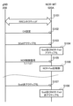
- FIG. 19 is a diagram showing a first operation example in which multiple serving cells by DC are used in the NCR device 500A. Duplicate explanations of operations similar to those in the case of CA described above will be omitted.
- step S201 the NCR-MT 520A establishes an RRC connection with the MN 200M (gNB 200) and enters the RRC connected state.
- the primary cell (serving cell C1) of MN200M is assigned to NCR-MT520A.
- the NCR-MT 520A may transmit the above-mentioned NCR capability information to the gNB 200.
- the NCR capability information may include information indicating that control of the NCR-Fwd 510A by the secondary cell is supported.
- the SN 200S may transmit an SN Addition Required message to the MN 200M to request that an SN be added.
- the message may include information indicating that an NCR is requested to be added.
- the MN 200M may execute step S202 in response to receiving the message.
- the MN 200M transmits an SN Addition Request message to the SN 200S on the inter-base station interface.
- the SN 200S receives the SN Addition Request message.
- the SN Addition Request message may include information indicating that an SCG for controlling the NCR device 500A is to be added.
- the SN Addition Request message may include information that associates the NCR-Fwd 510A with the secondary cell.
- the SN Addition Request message may include a list including at least one set of an identifier of the NCR-Fwd 510A, an identifier of the NCR device 500A, and/or an identifier of the NCR-MT 520A and a cell ID.
- the SN Addition Request message may include a list including at least one set of an identifier of the NCR-Fwd 510A, an identifier of the NCR device 500A, and/or an identifier of the NCR-MT 520A and a frequency identifier.
- the SN 200S transmits an SN Addition Request Acknowledgment message including the RRC Reconfiguration (RRC container) to be transmitted to the NCR-MT 520A to the MN 200M on the inter-base station interface.
- the MN 200M receives the SN Addition Request Acknowledgment message.
- the RRC Reconfiguration (RRC container) includes DC configuration information.
- the DC configuration information includes information that associates the secondary cell (serving cell C2) configured in the NCR-MT 520A with the NCR-Fwd 510A.
- the DC configuration information may include a list of at least one set of the secondary cell (serving cell C2) identifier and the NCR-Fwd 510A identifier.
- the DC configuration information may include information indicating which secondary cell (serving cell C2) controls the NCR-MT 520A (that is, establishes a control link).
- the DC setting information may include information indicating the operating frequency of the NCR-Fwd 510A.
- step S204 the MN 200M transmits the RRC Reconfiguration (DC configuration information) included in the SN Addition Request Acknowledgment message received in step S203 to the NCR-MT 520A.
- RRC Reconfiguration DC configuration information
- steps S205 to S210 are similar to the operations in steps S103 to S108 in FIG. 18.
- the secondary cell activation instruction/deactivation instruction may be transmitted from the SN 200S to the NCR-MT 520A.
- the SN 200S may transmit a message requesting activation or deactivation of the NCR to the MN 200M.
- the MN 200M may execute step S205 or S209.
- the SN 200S may request the MN 200M to remove the NCR settings.
- the MN 200M may transmit an SN Removal Request message to the SN 200S.
- the message may be a message for removing the settings of the NCR device 500A.
- the message may be a message for removing the settings of the NCR-Fwd 510A.
- This operation example is an operation example related to a secondary cell deactivation timer (also referred to as "sCellDeactivationTimer").
- sCellDeactivationTimer is a timer that the gNB 200 sets in the UE 100 in association with the secondary cell.
- the sCellDeactivationTimer is a timer for deactivating the secondary cell in response to a predetermined period of time in which there is no data communication in the secondary cell, and is used to measure the predetermined time. This allows unused secondary cells to be voluntarily deactivated.
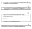
- FIG. 20 is a diagram for explaining sCellDeactivationTimer.
- "A” to “C” in FIG. 20 indicate the contents of the 3GPP technical specification “TS38.321” (i.e., MAC protocol specification), and “D” in FIG. 20 indicates the contents of the 3GPP technical specification "TS38.331” ( In other words, the contents of the RRC protocol specification are shown.
- the UE100 which is set with SCELLDEACTIVATIONTIMER, is a secondary SCE (SCE (SCE LL) does not activate.
- SCE SCE LL
- sCellDeactivationTimer can be individually set for each secondary cell (SCell).
- the UE 100 to which the sCellDeactivationTimer is set starts or restarts the sCellDeactivationTimer in response to activation of the secondary cell (SCell) associated with the sCellDeactivationTimer. Start.
- the UE100 which is set up with the ScellDeaCTIVATIONTIMER, has the PDCCH or the secondaricel (Scellelle) of the secondary cell (Scell) compatible with the ScellDEACTIVATIONTIMER. Resource on the serving cell to schedule
- the sCellDeactivationTimer is restarted. Further, the UE 100 restarts the sCellDeactivationTimer in response to receiving or transmitting data (MAC PDU) using the downlink or uplink resources allocated in advance in the configured grant.
- MAC PDU data
- the UE 100 applies infinity as the timer value of the sCellDeactivationTimer of the secondary cell.
- the NCR-MT 520A in the secondary cell that is, when providing a control link for the NCR-MT 520A in the secondary cell (serving cell C2)
- the following problems occur. Specifically, if sCellDeactivationTimer is set in the secondary cell (serving cell C2), there is a concern that the secondary cell (serving cell C2) will be deactivated due to expiration of sCellDeactivationTimer. For example, if the NCR control signal received on the control link is MAC CE, or if the NCR control signal received on the control link is DCI for non-scheduling, the NCR-MT520A will not be able to receive the NCR control signal.
- the gNB 200 that sets the secondary cell (serving cell C2) associated with the NCR-Fwd 510A to the NCR-MT 520A does not set sCellDeactivationTimer to the secondary cell. That is, the gNB 200 avoids setting the SCell deactivation timer on the secondary cell forming the control link of the NCR-Fwd 510A (setting the sCellDeactivationTimer on the secondary cell is prohibited). As a result, since the NCR-MT 520A applies an infinite value as the timer value of sCellDeactivationTimer, it is possible to prevent the secondary cell (serving cell C2) from being deactivated by sCellDeactivationTimer.
- the NCR-MT520A uses the timer value of the sCellDeactivationTimer (that is, the set sCellDeactivationTimer r) and set it to infinity as the timer value of sCellDeactivationTimer. may be applied. This can prevent the secondary cell (serving cell C2) from being deactivated by the sCellDeactivationTimer.
- FIG. 21 is a diagram showing this operation example. Duplicate explanations of operations similar to the first and second operation examples described above will be omitted.
- step S301 the NCR-MT 520A establishes an RRC connection with the gNB 200 and enters the RRC connected state.
- the primary cell (serving cell C1) of MN200M is assigned to NCR-MT520A.
- the gNB 200 performs CA settings or DC settings for the NCR-MT 520A.
- the gNB 200 sets the secondary cell (serving cell C2) that controls the NCR-Fwd 510A in the NCR-MT 520A.
- the settings include a set timer value of sCellDeactivationTimer.
- the settings may include information specifying whether to restart the sCellDeactivationTimer when receiving an NCR control signal (L1/L2 signal), particularly a DCI for NCR control.
- the information may include the cell ID of the secondary cell (serving cell C2) and/or the identifier of the NCR-Fwd 510A.
- step S303 the gNB 200 transmits a secondary cell (serving cell C2) activation instruction to the NCR-MT 520A.
- step S304 the NCR-MT 520A (or NCR device 500A) activates the secondary cell (serving cell C2) and the NCR-Fwd 510A in response to receiving the activation instruction. Furthermore, the NCR-MT 520A starts the sCellDeactivationTimer set for the secondary cell (serving cell C2) in step S302.
- step S306 the gNB 200 transmits the NCR control signal (L1/L2 signal) to the NCR-MT 520A on the control link in the secondary cell (serving cell C2).
- step S307 the NCR-MT 520A controls the NCR-Fwd 510A according to the NCR control signal. Furthermore, in response to receiving the NCR control signal (L1/L2 signal), the NCR-MT 520A restarts the sCellDeactivationTimer set for the secondary cell (serving cell C2) in step S302.
- the NCR-MT 520A deactivates the secondary cell (serving cell C2) when the sCellDeactivationTimer expires (step S308: YES). Further, the NCR-MT 520A (or NCR device 500A) may deactivate the corresponding NCR-Fwd 510A.
- the NCR-MT 520A detects that a failure has occurred in the control link (ie, secondary cell). NCR-MT 520A transmits information regarding the detected failure to gNB 200 on the primary cell. This allows the gNB 200 to understand that a failure has occurred in the control link.
- FIG. 22 is a diagram showing this operation example. Duplicate explanations of operations similar to the first to third operation examples described above will be omitted.
- step S401 the NCR-MT 520A establishes an RRC connection with the gNB 200 and enters the RRC connected state.
- the primary cell (serving cell C1) of MN200M is assigned to NCR-MT520A.
- the gNB 200 performs CA settings or DC settings for the NCR-MT 520A.
- the settings may include settings for monitoring the control link (eg, a quality threshold for the control link).
- the gNB 200 sets the secondary cell (serving cell C2) that controls the NCR-Fwd 510A in the NCR-MT 520A.
- step S403 the gNB 200 transmits a secondary cell (serving cell C2) activation instruction to the NCR-MT 520A.
- the NCR-MT 520A activates the secondary cell (serving cell C2) and the NCR-Fwd 510A in response to receiving the activation instruction.
- the NCR-MT 520A monitors the reception quality of the reference signal (SSB and/or CSI-RS) received on the control link.
- the NCR-MT 520A may perform the monitoring only when configured by the gNB 200.
- the reception quality may be RSRP/RSRQ/SINR of the control link.
- the NCR-MT 520A determines whether a failure of the control link is detected.
- the NCR-MT 520A may determine whether a failure corresponding to a radio link failure (RLF) has occurred in the control link.
- the NCR-MT 520A may determine that a failure has occurred when the measured reception quality is below a threshold.
- the threshold value may be set from the gNB 200.
- step S406 the NCR-MT 520A notifies the gNB 200 of control link failure information on the primary cell.
- the NCR-MT 520A transmits an RRC message such as an NCR Failure Information message to the gNB 200.
- gNB200 receives the message.
- the message may include an identifier of the NCR-Fwd 510A corresponding to the control link in which the failure has occurred, an identifier of the secondary cell, and/or information on the frequency in which the failure has occurred.
- the NCR-Fwd 510A relays the wireless signal transmitted between the gNB 200 and the UE 100.
- NCR-MT 520A performs wireless communication with gNB 200 via a control link to control NCR-Fwd 510A.
- the NCR-MT 520A performs predetermined control according to the failure.
- the NCR-MT 520A may transmit failure information of the control link or failure information of the NCR-Fwd 510A to the gNB 200 on the primary cell.
- the NCR-MT 520A detects that a failure has occurred in the control link.
- the NCR-MT 520A stops the operation of the NCR-Fwd 510A in response to the occurrence of a control link failure. If a failure occurs in the control link and the NCR-Fwd 510A operates in an uncontrolled state, problems such as interference may occur. Therefore, by stopping the operation of the NCR-Fwd 510A, the occurrence of such a problem can be avoided.
- the NCR-MT 520A may detect that the failure of the control link has been resolved.
- the NCR-MT 520A may send a notification to the gNB 200 in response to the resolution of the failure.
- FIG. 23 is a diagram showing this operation example. Duplicate explanations of operations similar to those of the above-described embodiments will be omitted.
- step S501 the NCR-MT 520A establishes an RRC connection with the gNB 200 and enters the RRC connected state.
- the gNB 200 may transmit an NCR control signal (L1/L2 signal) to the NCR-MT 520A on the control link.
- the NCR-MT 520A controls the NCR-Fwd 510A according to the NCR control signal.
- the NCR-MT 520A may monitor the reception quality of the reference signal (SSB and/or CSI-RS) received on the control link.
- the NCR-MT 520A may perform the monitoring only when configured by the gNB 200.
- the reception quality may be RSRP/RSRQ/SINR of the control link.
- the NCR-MT 520A determines whether a failure of the control link is detected.
- the NCR-MT 520A may determine whether a failure corresponding to a radio link failure (RLF) has occurred in the control link.
- the NCR-MT 520A may determine that a failure has occurred when the measured reception quality is below a threshold.
- the threshold value may be set from the gNB 200.
- the NCR-MT520A may determine that a control link failure has been detected if any of the following events occur: - A failure equivalent to RLF has occurred in the control link. - RLF has occurred in the primary cell. - RRC Reestablishment has started. - MCG Failure Information regarding MCG failure has been sent to gNB 200. - SCG Failure regarding SCG failure has occurred. Information has been sent to the gNB 200 - Transition to RRC idle state or RRC inactive state (for example, RRC Reestablishment has failed) ⁇ Connected to a cell different from the current serving cell
- step S504 If it is determined that a failure in the control link has been detected (step S503: YES), in step S504, the NCR-MT 520A (or the NCR device 500A) stops the operation of the NCR-Fwd 510A (that is, the relay operation of the wireless signal). .
- step S505 the NCR-MT 520A may determine whether the failure of the control link has been resolved (returned to normal).
- step S506 the NCR-MT 520A may send a notification to the gNB 200 indicating that the NCR-Fwd 510A is inactive.
- the gNB 200 may perform settings and control for the NCR device 500A again in response to receiving the notification.
- the gNB 200 may control the NCR device 500A to restore the previously performed settings and control state (that is, reactivate the NCR-Fwd 510A).
- the gNB 200 sets the content of predetermined control for the NCR-Fwd 510A (that is, control when a failure occurs) in the NCR-MT 520A.
- NCR-MT520A detects that a failure has occurred in the control link.
- the NCR-MT 520A controls the NCR-Fwd 510A based on the settings set by the gNB 200 in response to the occurrence of a failure in the control link.
- the gNB 200 may set in the NCR-MT 520A whether or not to continue the operation of the NCR-Fwd 510A when a failure occurs in the control link.
- FIG. 24 is a diagram showing this operation example. Duplicate explanations of operations similar to those of the above-described embodiments will be omitted.
- step S601 the NCR-MT 520A establishes an RRC connection with the gNB 200 and enters the RRC connected state.
- the gNB 200 transmits to the NCR-MT 520A configuration information indicating the control content of the NCR-Fwd 510A when a failure occurs in the control link.
- the gNB 200 may include the configuration information in an RRC message (for example, an RRC Reconfiguration message) and transmit it to the NCR-MT 520A.
- NCR-MT520A receives the configuration information.
- the gNB 200 may transmit an NCR control signal (L1/L2 signal) to the NCR-MT 520A on the control link.
- the NCR-MT 520A controls the NCR-Fwd 510A according to the NCR control signal.
- the setting information in step S602 indicates whether to stop the operation of the NCR-Fwd 510A, to discard the settings of the NCR-Fwd 510A, or to continue the operation of the NCR-Fwd 510A as the control content when a failure occurs in the control link. It may also include information specifying whether the When continuing the operation of the NCR-Fwd 510A, the configuration information may include an NCR control signal indicating a beamforming method when a failure occurs in the control link.
- the NCR-MT 520A may monitor the reception quality of the reference signal (SSB and/or CSI-RS) received on the control link.
- step S604 the NCR-MT 520A determines whether a failure of the control link has been detected using the method described above.
- step S605 the NCR-MT 520A performs the control set in step S602 on the NCR-Fwd 510A.
- the NCR-MT 520A (or the NCR device 500A) may continue the operation of the NCR-Fwd 510A according to content that has already been set and controlled.
- the NCR-MT 520A may continue the operation of the NCR-Fwd 510A according to the NCR control signal set in step S602.
- steps S606 and S607 are similar to those in the embodiment described above.
- the NCR-MT 520A detects that a failure has occurred in the NCR-Fwd 510A (for example, that the NCR-Fwd 510A has failed).
- the NCR-MT 520A transmits failure information of the NCR-Fwd 510A to the gNB 200 in response to occurrence of a failure of the NCR-Fwd 510A.
- FIG. 25 is a diagram showing this operation example. Duplicate explanations of operations similar to those of the above-described embodiments will be omitted.
- the NCR-MT 520A establishes an RRC connection with the gNB 200 and enters the RRC connected state.
- the gNB 200 may perform settings related to monitoring the NCR-Fwd 510A for the NCR-MT 520A.
- the gNB 200 may transmit an NCR control signal (L1/L2 signal) to the NCR-MT 520A on the control link.
- the NCR-MT 520A controls the NCR-Fwd 510A according to the NCR control signal.
- the NCR-MT 520A may monitor the operation of the NCR-Fwd 510A.
- the NCR-MT 520A may monitor at least one of the load state, control delay time (control response time), and heat generation amount of the NCR-Fwd 510A.
- the NCR-MT 520A determines whether a failure of the NCR-Fwd 510A is detected. For example, the NCR-MT520A may determine that a control link failure has been detected if any of the following events occur: - A failure has occurred in the NCR-Fwd510A. - The processing of the NCR-Fwd510A has not kept up with the settings and control from the gNB200. For example, the NCR-Fwd 510A could not be controlled in response to the NCR control signal from the gNB 200. - The load on the NCR-Fwd 510A (for example, the usage rate of hardware resources) became higher than a threshold. Note that the threshold value may be set from the gNB 200.
- step S704 the NCR-MT 520A transmits failure information regarding the detected failure to the gNB 200.
- the gNB 200 desires the failure information.
- the NCR-MT 520A may transmit an RRC message including the failure information, for example, a message such as NCR Failure Information or a UE Assistance Information message to the gNB 200.
- the message may include at least one of the following information elements: ⁇ Information element indicating failure occurrence of NCR-Fwd510A ⁇ Information element indicating processing delay, load increase, or overheating of NCR-Fwd510A ⁇ Information element indicating failure occurrence in control link ⁇ Desired setting/control value of NCR-Fwd510A. For example, it may be a preference value for the upper limit of the number of antennas to be controlled and/or the upper limit of the frequency bandwidth.
- the gNB 200 may change the settings and control for the NCR device 500A according to the desired settings and control values. - Identifier of the NCR-Fwd 510A where the failure has occurred.
- the gNB 200 that has received the failure information in step S704 selects one of the following as the control content for dealing with the failure: to stop the operation of the NCR-Fwd 510A, to discard the settings of the NCR-Fwd 510A, or to continue the operation of the NCR-Fwd 510A.
- Information specifying whether to use the NCR-MT 520A may be sent to the NCR-MT 520A.
- the NCR-MT 520A may determine whether the failure of the NCR-Fwd 510A has been resolved (returned to normal).
- NCR-MT 520A may transmit a notification to gNB 200 indicating that the failure of NCR-Fwd 510A has been resolved.
- the notification may include the identifier of the NCR-Fwd 510A whose fault has been resolved.
- the relay device is an RIS (Reconfigurable Intelligent Surface) device 500B that changes the propagation direction of incident radio waves (wireless signals) by reflection or refraction.
- RIS Reconfigurable Intelligent Surface
- RIS is a type of repeater (hereinafter also referred to as "RIS-Fwd") that can perform beam forming (directivity control) like NCR by changing the characteristics of metamaterial.
- the range (distance) of the beam may also be changeable by controlling the reflection direction and/or refraction direction of each unit element.
- the configuration is such that it is possible to control the reflection direction and/or refraction direction of each unit element, and also to focus on a nearby UE (direct the beam) or focus on a far UE (direct the beam). Good too.
- the RIS device 500B has a new UE (hereinafter referred to as "RIS-MT") 520B which is a control terminal for controlling the RIS-Fwd 510B.
- the RIS-MT 520B controls the RIS-Fwd 510B in cooperation with the gNB 200 by establishing a wireless connection with the gNB 200 and performing wireless communication with the gNB 200.
- the RIS-Fwd 510B may be a reflective RIS. Such a RIS-Fwd 510B changes the propagation direction of the incident radio waves by reflecting them. Here, the reflection angle of the radio waves can be variably set.
- the RIS-Fwd 510B reflects the radio waves incident from the gNB 200 toward the UE 100.
- the RIS-Fwd 510B may be a transparent RIS. Such a RIS-Fwd 510B changes the propagation direction of the incident radio waves by refracting them.
- the refraction angle of the radio wave can be variably set.
- FIG. 27 is a diagram showing a configuration example of a RIS-Fwd (repeater) 510B and a RIS-MT (control terminal) 520B according to the second embodiment.
- the RIS-MT 520B includes a receiving section 521, a transmitting section 522, and a control section 523.
- Such a configuration is similar to the first embodiment described above.
- RIS-Fwd 510B includes RIS 511B and RIS control section 512B.
- RIS511B is a metasurface configured using metamaterial.
- RIS511B is constructed by arranging very small structures in an array with respect to the wavelength of radio waves, and by making the structures have different shapes depending on the placement location, the direction and/or beam shape of the reflected wave can be arbitrarily changed. It is possible to design.
- RIS 511B may be a transparent dynamic metasurface.
- RIS511B is constructed by stacking a transparent glass substrate on a transparent metasurface substrate in which a large number of small structures are arranged regularly, and by slightly moving the stacked glass substrates, it creates a mode that transmits incident radio waves. It may be possible to dynamically control three patterns: a mode in which a part of the radio wave is transmitted and a part reflected, and a mode in which all the radio waves are reflected.
- the RIS control unit 512B controls the RIS 511B according to the RIS control signal from the control unit 523 of the RIS-MT 520B.
- RIS control unit 512B may include at least one processor and at least one actuator.
- the processor decodes the RIS control signal from the control unit 523 of the RIS-MT 520B and drives the actuator in accordance with the RIS control signal.
- FIG. 28 is a diagram illustrating an example of beam sweeping according to another embodiment.
- the gNB 200 transmits a plurality of beams (in the illustrated example, SSB3 to SSB5 beams) with the same transmission weight toward the NCR device 500A for the backhaul link.
- the NCR device 500A (NCR-Fwd 510A) autonomously transmits the plurality of beams (SSB3 to SSB5 beams) with different transmission weights in different directions for the access link.
- the NCR device 500A (NCR-MT 520A) may autonomously control the NCR-Fwd 510A based on the settings from the gNB 200 when a failure occurs.
- operation flows are not limited to being implemented separately, but can be implemented by combining two or more operation flows. For example, some steps of one operation flow may be added to another operation flow, or some steps of one operation flow may be replaced with some steps of another operation flow. In each flow, it is not necessary to execute all steps, and only some steps may be executed.
- the base station may be an NR base station (gNB)
- the base station may be an LTE base station (eNB).
- the base station may be a relay node such as an IAB (Integrated Access and Backhaul) node.
- the base station may be a DU (Distributed Unit) of an IAB node.
- a program may be provided that causes a computer to execute each process performed by the UE 100 (NCR-MT520A, RIS-MT520B) or the gNB 200.
- the program may be recorded on a computer readable medium.
- Computer-readable media allow programs to be installed on a computer.
- the computer-readable medium on which the program is recorded may be a non-transitory recording medium.
- the non-transitory recording medium is not particularly limited, but may be a recording medium such as a CD-ROM or a DVD-ROM.
- the circuits that execute each process performed by the UE 100 or the gNB 200 may be integrated, and at least a portion of the UE 100 or the gNB 200 may be configured as a semiconductor integrated circuit (chip set, SoC: System on a chip).
- the terms “based on” and “depending on/in response to” refer to “based solely on” and “depending on,” unless expressly stated otherwise. does not mean “only according to”. Reference to “based on” means both “based solely on” and “based at least in part on.” Similarly, the phrase “in accordance with” means both “in accordance with” and “in accordance with, at least in part.”
- the terms “include”, “comprise”, and variations thereof do not mean to include only the listed items, but may include only the listed items or in addition to the listed items. This means that it may contain further items. Also, as used in this disclosure, the term “or” is not intended to be exclusive OR. Furthermore, any reference to elements using the designations "first,” “second,” etc.
- a communication method using a relay device in a mobile communication system comprising: A repeater included in the relay device relays a wireless signal transmitted between a base station and a user device; A control terminal included in the relay device performs wireless communication with the base station via a control link to control the relay; the control terminal detecting that a failure has occurred in the control link or the repeater; A communication method comprising: the control terminal performing predetermined control according to the failure.
- the detecting step includes detecting that a failure has occurred in the control link,
- the base station further comprises a step of setting the content of the predetermined control for the repeater in the control terminal,
- the detecting step includes detecting that a failure has occurred in the control link,
- the communication method according to supplementary note 1 or 2 wherein the step of performing the predetermined control includes the step of controlling the repeater according to the settings set by the base station in response to occurrence of a failure in the control link.
- the detecting step includes detecting that a failure has occurred in the repeater, 5.
- a relay device used in a mobile communication system a repeater that relays wireless signals transmitted between the base station and the user equipment; a control terminal that controls the repeater by performing wireless communication with the base station via a control link, When the control terminal detects that a failure has occurred in the control link or the repeater, the control terminal performs predetermined control according to the failure.
- Relay device When the control terminal detects that a failure has occurred in the control link or the repeater, the control terminal performs predetermined control according to the failure.
- Mobile communication system 100 UE 200:gNB 210: Transmitting section 220: Receiving section 230: Control section 240: Backhaul communication section 500A: NCR device 500B: RIS device 511A: Wireless unit 511a: Antenna section 511b: RF circuit 511c: Directivity control section 512A: NCR control section 512B : RIS control unit 521 : Receiving unit 522 : Transmitting unit 523 : Control unit 530 : Interface
Abstract
This communication method, which uses a relay device in a wireless communication system, comprises: a step in which a repeater included in the relay device relays a wireless signal transmitted between a base station and a user device; a step in which a control terminal included in the relay device performs wireless communication with the base station through a control link and controls the repeater; a step in which the control terminal detects that an obstacle occurs in the control link or the repeater; and a step in which the control terminal performs a prescribed control in response to the obstacle.
Description
本開示は、移動通信システムで用いる通信方法及び中継装置に関する。
The present disclosure relates to a communication method and a relay device used in a mobile communication system.
近年、第5世代(5G)の移動通信システムが注目されている。5Gシステムの無線アクセス技術であるNR(New Radio)は、第4世代の無線アクセス技術であるLTE(Long Term Evolution)に比べて、高周波数帯による広帯域伝送が可能である。
In recent years, fifth generation (5G) mobile communication systems have been attracting attention. NR (New Radio), which is a radio access technology for the 5G system, is capable of wideband transmission using a high frequency band, compared to LTE (Long Term Evolution), which is a fourth generation radio access technology.
ミリ波帯又はテラヘルツ波帯といった高周波数帯の無線信号(電波)は、高い直進性を有するため、基地局のカバレッジの縮小が課題となる。このような課題を解決するために、基地局とユーザ装置との間で無線信号を中継する中継装置の一種であって、ネットワークから制御可能なリピータ装置が注目されている(例えば、非特許文献1参照)。このようなリピータ装置は、例えば、基地局から受信する無線信号を増幅するとともに指向性送信により送信することで、干渉の発生を抑制しつつ基地局のカバレッジを拡張できる。
Since radio signals (radio waves) in high frequency bands such as millimeter wave bands or terahertz wave bands have high straightness, reducing the coverage of base stations becomes an issue. In order to solve such problems, repeater devices, which are a type of relay device that relays wireless signals between base stations and user equipment, and can be controlled from a network, are attracting attention (for example, in the non-patent literature (see 1). Such a repeater device can expand the coverage of a base station while suppressing the occurrence of interference, for example, by amplifying a radio signal received from a base station and transmitting it using directional transmission.
第1の態様に係る通信方法は、移動通信システムにおいて中継装置を用いる通信方法であって、前記中継装置に含まれる中継器が、基地局とユーザ装置との間で伝送される無線信号を中継するステップと、前記中継装置に含まれる制御端末が、制御リンクを介して前記基地局との無線通信を行って前記中継器を制御するステップと、前記制御端末が、前記制御リンク又は前記中継器に障害が発生したことを検知するステップと、前記制御端末が、前記障害に応じた所定制御を行うステップと、を有する。
A communication method according to a first aspect is a communication method using a relay device in a mobile communication system, wherein a repeater included in the relay device relays a wireless signal transmitted between a base station and a user device. a step in which a control terminal included in the relay device performs wireless communication with the base station via a control link to control the repeater; and a step of causing the control terminal to perform predetermined control in response to the failure.
第2の態様に係る中継装置は、移動通信システムにおいて用いる中継装置であって、基地局とユーザ装置との間で伝送される無線信号を中継する中継器と、制御リンクを介して前記基地局との無線通信を行って前記中継器を制御する制御端末と、を備える。前記制御端末は、前記制御リンク又は前記中継器に障害が発生したことを検知した場合、前記障害に応じた所定制御を行う。
A relay device according to a second aspect is a relay device used in a mobile communication system, and includes a relay device that relays wireless signals transmitted between a base station and a user device, and a relay device that connects a base station to the base station via a control link. and a control terminal that controls the repeater by performing wireless communication with the repeater. When the control terminal detects that a failure has occurred in the control link or the repeater, the control terminal performs predetermined control according to the failure.
リピータ装置等の中継装置をネットワークから制御する場合において、具体的にどのようにして中継装置を制御するかについての制御技術は未だ確立しておらず、中継装置を用いて効率的なカバレッジ拡張を行うことは現状では難しい。
When controlling relay devices such as repeaters from a network, the control technology for specifically controlling the relay devices has not yet been established, and it is difficult to efficiently expand coverage using relay devices. This is currently difficult to do.
そこで、本開示は、基地局とユーザ装置との間で中継伝送を行う中継装置を適切に制御可能とすることを目的とする。
Therefore, an object of the present disclosure is to enable appropriate control of a relay device that performs relay transmission between a base station and a user device.
図面を参照しながら、実施形態に係る移動通信システムについて説明する。図面の記載において、同一又は類似の部分には同一又は類似の符号を付している。
A mobile communication system according to an embodiment will be described with reference to the drawings. In the description of the drawings, the same or similar parts are designated by the same or similar symbols.
(1)第1実施形態
まず、第1実施形態について説明する。第1実施形態に係る中継装置は、ネットワークからの制御が可能なリピータ装置である。 (1) First Embodiment First, the first embodiment will be described. The relay device according to the first embodiment is a repeater device that can be controlled from a network.
まず、第1実施形態について説明する。第1実施形態に係る中継装置は、ネットワークからの制御が可能なリピータ装置である。 (1) First Embodiment First, the first embodiment will be described. The relay device according to the first embodiment is a repeater device that can be controlled from a network.
(1.1)移動通信システムの概要
図1は、第1実施形態に係る移動通信システムの構成を示す図である。移動通信システム1は、第3世代パートナーシッププロジェクト(3GPP)(登録商標。以下同じ)規格の第5世代システム(5GS:5th Generation System)に準拠する。以下において、5GSを例に挙げて説明するが、移動通信システムにはLTE(Long Term Evolution)システムが少なくとも部分的に適用されてもよい。移動通信システムには第6世代(6G)システムが少なくとも部分的に適用されてもよい。 (1.1) Overview of Mobile Communication System FIG. 1 is a diagram showing the configuration of a mobile communication system according to the first embodiment. Themobile communication system 1 complies with the 5th Generation System (5GS) of the 3rd Generation Partnership Project (3GPP) (registered trademark, same hereinafter) standard. Although 5GS will be described as an example below, an LTE (Long Term Evolution) system may be applied at least partially to the mobile communication system. A sixth generation (6G) system may be applied at least in part to the mobile communication system.
図1は、第1実施形態に係る移動通信システムの構成を示す図である。移動通信システム1は、第3世代パートナーシッププロジェクト(3GPP)(登録商標。以下同じ)規格の第5世代システム(5GS:5th Generation System)に準拠する。以下において、5GSを例に挙げて説明するが、移動通信システムにはLTE(Long Term Evolution)システムが少なくとも部分的に適用されてもよい。移動通信システムには第6世代(6G)システムが少なくとも部分的に適用されてもよい。 (1.1) Overview of Mobile Communication System FIG. 1 is a diagram showing the configuration of a mobile communication system according to the first embodiment. The
移動通信システム1は、ユーザ装置(UE:User Equipment)100と、5Gの無線アクセスネットワーク(NG-RAN:Next Generation Radio Access Network)10と、5Gのコアネットワーク(5GC:5G Core Network)20とを有する。以下において、NG-RAN10を単にRAN10と呼ぶことがある。また、5GC20を単にコアネットワーク(CN)20と呼ぶことがある。
The mobile communication system 1 includes a user equipment (UE) 100, a 5G radio access network (NG-RAN) 10, and a 5G core network (5GC). work) 20 and have Below, the NG-RAN 10 may be simply referred to as RAN 10. Further, the 5GC 20 may be simply referred to as the core network (CN) 20.
UE100は、移動可能な無線通信装置である。UE100は、ユーザにより利用される装置であればどのような装置であっても構わない。例えば、UE100は、携帯電話端末(スマートフォンを含む)及び/又はタブレット端末、ノートPC、通信モジュール(通信カード又はチップセットを含む)、センサ若しくはセンサに設けられる装置、車両若しくは車両に設けられる装置(Vehicle UE)、飛行体若しくは飛行体に設けられる装置(Aerial UE)である。
The UE 100 is a mobile wireless communication device. The UE 100 may be any device as long as it is used by a user. For example, the UE 100 may be a mobile phone terminal (including a smartphone) and/or a tablet terminal, a notebook PC, a communication module (including a communication card or a chipset), a sensor or a device provided in the sensor, a vehicle or a device provided in the vehicle ( Vehicle UE), a flying object, or a device installed on a flying object (Aerial UE).
NG-RAN10は、基地局(5Gシステムにおいて「gNB」と呼ばれる)200を含む。gNB200は、基地局間インターフェイスであるXnインターフェイスを介して相互に接続される。gNB200は、1又は複数のセルを管理する。gNB200は、自セルとの接続を確立したUE100との無線通信を行う。gNB200は、無線リソース管理(RRM)機能、ユーザデータ(以下、単に「データ」という)のルーティング機能、モビリティ制御・スケジューリングのための測定制御機能等を有する。「セル」は、無線通信エリアの最小単位を示す用語として用いられる。「セル」は、UE100との無線通信を行う機能又はリソースを示す用語としても用いられる。1つのセルは1つのキャリア周波数(以下、単に「周波数」と呼ぶ)に属する。
The NG-RAN 10 includes a base station (called "gNB" in the 5G system) 200. gNB200 is mutually connected via the Xn interface which is an interface between base stations. gNB200 manages one or more cells. The gNB 200 performs wireless communication with the UE 100 that has established a connection with its own cell. The gNB 200 has a radio resource management (RRM) function, a routing function for user data (hereinafter simply referred to as "data"), a measurement control function for mobility control/scheduling, and the like. “Cell” is a term used to indicate the smallest unit of wireless communication area. "Cell" is also used as a term indicating a function or resource for performing wireless communication with the UE 100. One cell belongs to one carrier frequency (hereinafter simply referred to as "frequency").
gNB200は、集約ユニット(CU:Central Unit)と分散ユニット(DU: Distributed Unit)とに機能分割されていてもよい。CUは、DUを制御する。CUは、後述のプロトコルスタックに含まれる上位レイヤ、例えば、RRCレイヤ、SDAPレイヤ、及びPDCPレイヤを含むユニットである。CUは、バックホールインターフェイスであるNGインターフェイスを介してコアネットワークと接続される。CUは、基地局間インターフェイスであるXnインターフェイスを介して隣接基地局と接続される。DUは、セルを形成する。DU202は、後述のプロトコルスタックに含まれる下位レイヤ、例えば、RLCレイヤ、MACレイヤ、及びPHYレイヤを含むユニットである。DUは、フロントホールインターフェイスであるF1インターフェイスを介してCUと接続される。
The gNB 200 may be functionally divided into a central unit (CU) and a distributed unit (DU). CU controls DU. The CU is a unit that includes upper layers included in a protocol stack described below, such as an RRC layer, an SDAP layer, and a PDCP layer. The CU is connected to the core network via the NG interface, which is a backhaul interface. The CU is connected to adjacent base stations via an Xn interface, which is an interface between base stations. DUs form cells. The DU 202 is a unit that includes lower layers included in a protocol stack described below, such as an RLC layer, a MAC layer, and a PHY layer. The DU is connected to the CU via the F1 interface, which is a fronthaul interface.
なお、gNBがLTEのコアネットワークであるEPC(Evolved Packet Core)に接続することもできる。LTEの基地局が5GCに接続することもできる。LTEの基地局とgNBとが基地局間インターフェイスを介して接続されることもできる。
Note that the gNB can also be connected to EPC (Evolved Packet Core), which is the core network of LTE. LTE base stations can also connect to 5GC. An LTE base station and a gNB can also be connected via an inter-base station interface.
5GC20は、AMF(Access and Mobility Management Function)及びUPF(User Plane Function)300を含む。AMFは、UE100に対する各種モビリティ制御等を行う。AMFは、NAS(Non-Access Stratum)シグナリングを用いてUE100と通信することにより、UE100のモビリティを管理する。UPFは、データの転送制御を行う。AMF及びUPFは、基地局-コアネットワーク間インターフェイスであるNGインターフェイスを介してgNB200と接続される。
5GC20 includes an AMF (Access and Mobility Management Function) and a UPF (User Plane Function) 300. The AMF performs various mobility controls for the UE 100. AMF manages the mobility of UE 100 by communicating with UE 100 using NAS (Non-Access Stratum) signaling. The UPF controls data transfer. AMF and UPF are connected to gNB 200 via an NG interface that is a base station-core network interface.
図2は、データを取り扱うユーザプレーンの無線インターフェイスのプロトコルスタックの構成を示す図である。
FIG. 2 is a diagram showing the configuration of a protocol stack of a user plane wireless interface that handles data.
ユーザプレーンの無線インターフェイスプロトコルは、物理(PHY)レイヤと、MAC(Medium Access Control)レイヤと、RLC(Radio Link Control)レイヤと、PDCP(Packet Data Convergence Protocol)レイヤと、SDAP(Service Data Adaptation Protocol)レイヤとを有する。
The user plane radio interface protocols include the physical (PHY) layer, MAC (Medium Access Control) layer, RLC (Radio Link Control) layer, and PDCP (Packet Data Convergence Protocol). col) layer and SDAP (Service Data Adaptation Protocol) It has a layer.
PHYレイヤは、符号化・復号、変調・復調、アンテナマッピング・デマッピング、及びリソースマッピング・デマッピングを行う。UE100のPHYレイヤとgNB200のPHYレイヤとの間では、物理チャネルを介してデータ及び制御情報が伝送される。なお、UE100のPHYレイヤは、gNB200から物理下りリンク制御チャネル(PDCCH)上で送信される下りリンク制御情報(DCI)を受信する。具体的には、UE100は、無線ネットワーク一時識別子(RNTI)を用いてPDCCHのブラインドデコーディングを行い、復号に成功したDCIを自UE宛てのDCIとして取得する。gNB200から送信されるDCIには、RNTIによってスクランブルされたCRCパリティビットが付加されている。
The PHY layer performs encoding/decoding, modulation/demodulation, antenna mapping/demapping, and resource mapping/demapping. Data and control information are transmitted between the PHY layer of the UE 100 and the PHY layer of the gNB 200 via a physical channel. Note that the PHY layer of the UE 100 receives downlink control information (DCI) transmitted from the gNB 200 on the physical downlink control channel (PDCCH). Specifically, the UE 100 performs blind decoding of the PDCCH using a radio network temporary identifier (RNTI), and acquires the successfully decoded DCI as the DCI addressed to its own UE. A CRC parity bit scrambled by the RNTI is added to the DCI transmitted from the gNB 200.
また、gNB200は、同期信号ブロック(SSB:Synchronization Signal/PBCH block)を送信する。例えば、SSBは、連続する4つのOFDM(Orthogonal Frequency Division Multiplex)シンボルから構成され、プライマリ同期信号(PSS)、セカンダリ同期信号(SSS)、物理ブロードキャストチャネル(PBCH)/マスタ情報ブロック(MIB)、及び、PBCHの復調参照信号(DMRS)が配置される。SSBの帯域幅は、例えば、240の連続するサブキャリア、すなわち、20RBの帯域幅である。
Additionally, the gNB 200 transmits a synchronization signal block (SSB: Synchronization Signal/PBCH block). For example, SSB consists of four consecutive OFDM (Orthogonal Frequency Division Multiplex) symbols, including a primary synchronization signal (PSS), a secondary synchronization signal (SSS), a physical broadcast channel (PBCH)/master information block (MIB), and , PBCH demodulation reference signals (DMRS) are arranged. The bandwidth of SSB is, for example, a bandwidth of 240 consecutive subcarriers, or 20RB.
MACレイヤは、データの優先制御、ハイブリッドARQ(HARQ:Hybrid Automatic Repeat reQuest)による再送処理、及びランダムアクセスプロシージャ等を行う。UE100のMACレイヤとgNB200のMACレイヤとの間では、トランスポートチャネルを介してデータ及び制御情報が伝送される。gNB200のMACレイヤはスケジューラを含む。スケジューラは、上下リンクのトランスポートフォーマット(トランスポートブロックサイズ、変調・符号化方式(MCS:Modulation and Coding Scheme))及びUE100への割当リソースブロックを決定する。
The MAC layer performs data priority control, retransmission processing using Hybrid ARQ (HARQ: Hybrid Automatic Repeat reQuest), random access procedure, etc. Data and control information are transmitted between the MAC layer of UE 100 and the MAC layer of gNB 200 via a transport channel. The MAC layer of gNB 200 includes a scheduler. The scheduler determines uplink and downlink transport formats (transport block size, modulation and coding scheme (MCS)) and resource blocks to be allocated to the UE 100.
RLCレイヤは、MACレイヤ及びPHYレイヤの機能を利用してデータを受信側のRLCレイヤに伝送する。UE100のRLCレイヤとgNB200のRLCレイヤとの間では、論理チャネルを介してデータ及び制御情報が伝送される。
The RLC layer uses the functions of the MAC layer and PHY layer to transmit data to the RLC layer on the receiving side. Data and control information are transmitted between the RLC layer of UE 100 and the RLC layer of gNB 200 via logical channels.
PDCPレイヤは、ヘッダ圧縮・伸張、及び暗号化・復号化等を行う。
The PDCP layer performs header compression/expansion, encryption/decryption, etc.
SDAPレイヤは、コアネットワークがQoS(Quality of Service)制御を行う単位であるIPフローとAS(Access Stratum)がQoS制御を行う単位である無線ベアラとのマッピングを行う。なお、RANがEPCに接続される場合は、SDAPが無くてもよい。
The SDAP layer performs mapping between an IP flow, which is a unit in which the core network performs QoS (Quality of Service) control, and a radio bearer, which is a unit in which an AS (Access Stratum) performs QoS control. Note that if the RAN is connected to the EPC, the SDAP may not be provided.
図3は、シグナリング(制御信号)を取り扱う制御プレーンの無線インターフェイスのプロトコルスタックの構成を示す図である。
FIG. 3 is a diagram showing the configuration of the protocol stack of the wireless interface of the control plane that handles signaling (control signals).
制御プレーンの無線インターフェイスのプロトコルスタックは、図2に示したSDAPレイヤに代えて、RRC(Radio Resource Control)レイヤ及びNAS(Non-Access Stratum)レイヤを有する。
The protocol stack of the wireless interface of the control plane includes an RRC (Radio Resource Control) layer and a NAS (Non-Access Stratum) layer instead of the SDAP layer shown in FIG. 2.
UE100のRRCレイヤとgNB200のRRCレイヤとの間では、各種設定のためのRRCシグナリングが伝送される。RRCレイヤは、無線ベアラの確立、再確立及び解放に応じて、論理チャネル、トランスポートチャネル、及び物理チャネルを制御する。UE100のRRCとgNB200のRRCとの間にコネクション(RRCコネクション)がある場合、UE100はRRCコネクティッド状態にある。UE100のRRCとgNB200のRRCとの間にコネクション(RRCコネクション)がない場合、UE100はRRCアイドル状態にある。UE100のRRCとgNB200のRRCとの間のコネクションがサスペンドされている場合、UE100はRRCインアクティブ状態にある。
RRC signaling for various settings is transmitted between the RRC layer of the UE 100 and the RRC layer of the gNB 200. The RRC layer controls logical, transport and physical channels according to the establishment, re-establishment and release of radio bearers. When there is a connection (RRC connection) between the RRC of the UE 100 and the RRC of the gNB 200, the UE 100 is in an RRC connected state. When there is no connection (RRC connection) between the RRC of the UE 100 and the RRC of the gNB 200, the UE 100 is in an RRC idle state. When the connection between the RRC of the UE 100 and the RRC of the gNB 200 is suspended, the UE 100 is in an RRC inactive state.
RRCレイヤの上位に位置するNASレイヤは、セッション管理及びモビリティ管理等を行う。UE100のNASレイヤとAMF300AのNASレイヤとの間では、NASシグナリングが伝送される。なお、UE100は、無線インターフェイスのプロトコル以外にアプリケーションレイヤ等を有する。また、NASレイヤよりも下位のレイヤをASレイヤと呼ぶ。
The NAS layer located above the RRC layer performs session management, mobility management, etc. NAS signaling is transmitted between the NAS layer of the UE 100 and the NAS layer of the AMF 300A. Note that the UE 100 has an application layer and the like in addition to the wireless interface protocol. Further, a layer lower than the NAS layer is called an AS layer.
(1.2)中継装置の適用シナリオの一例
図4及び図5は、第1実施形態に係るNCR装置の適用シナリオの一例を示す図である。 (1.2) An example of an application scenario of the relay device FIGS. 4 and 5 are diagrams showing an example of an application scenario of the NCR device according to the first embodiment.
図4及び図5は、第1実施形態に係るNCR装置の適用シナリオの一例を示す図である。 (1.2) An example of an application scenario of the relay device FIGS. 4 and 5 are diagrams showing an example of an application scenario of the NCR device according to the first embodiment.
5G/NRは、4G/LTEに比べて、高周波数帯による広帯域伝送が可能である。ミリ波帯又はテラヘルツ波帯といった高周波数帯の無線信号は、高い直進性を有するため、gNB200のカバレッジの縮小が課題となる。図4において、UE100は、gNB200のカバレッジエリア外、例えば、gNB200から直接的に無線信号を受信可能なエリアの外に位置していてもよい。gNB200とUE100との間に遮蔽物が存在し、UE100がgNB200との見通し内での通信ができない状態であってもよい。
Compared to 4G/LTE, 5G/NR is capable of wideband transmission using a high frequency band. Since radio signals in high frequency bands such as millimeter wave bands or terahertz wave bands have high straightness, reducing the coverage of the gNB 200 becomes an issue. In FIG. 4, the UE 100 may be located outside the coverage area of the gNB 200, for example, outside the area where wireless signals can be directly received from the gNB 200. A shield may exist between the gNB 200 and the UE 100, and the UE 100 may be unable to communicate within line of sight with the gNB 200.
図4に示すように、gNB200とUE100との間で無線信号を中継する中継装置の一種であるリピータ装置(500A)であって、ネットワークからの制御が可能なリピータ装置(500A)を移動通信システム1に導入する。以下において、このようなリピータ装置をNCR(Network-Controlled Repeater)装置と称する。このようなリピータ装置は、スマートリピータ装置と称されてもよい。
As shown in FIG. 4, a mobile communication system uses a repeater device (500A), which is a type of relay device that relays wireless signals between the gNB 200 and the UE 100, and which can be controlled from a network. 1. In the following, such a repeater device will be referred to as an NCR (Network-Controlled Repeater) device. Such a repeater device may be referred to as a smart repeater device.
例えば、NCR装置500Aは、gNB200から受信する無線信号(電波)を増幅するとともに指向性送信により送信する。具体的には、NCR装置500Aは、gNB200がビームフォーミングにより送信する無線信号を受信する。そして、NCR装置500Aは、受信した無線信号を復調・変調することなく増幅し、増幅した無線信号を指向性送信により送信する。ここで、NCR装置500Aは、固定された指向性(ビーム)で無線信号を送信してもよい。NCR装置500Aは、可変の(適応的な)指向性ビームにより無線信号を送信してもよい。これにより、gNB200のカバレッジを効率的に拡張できる。第1実施形態において、gNB200からUE100への下りリンクの通信にNCR装置500Aを適用する場合を主として想定するが、UE100からgNB200への上りリンクの通信にもNCR装置500Aを適用可能である。
For example, the NCR device 500A amplifies a wireless signal (radio wave) received from the gNB 200 and transmits it by directional transmission. Specifically, the NCR device 500A receives a wireless signal transmitted by the gNB 200 by beamforming. Then, the NCR device 500A amplifies the received radio signal without demodulating or modulating it, and transmits the amplified radio signal by directional transmission. Here, the NCR device 500A may transmit a wireless signal with fixed directivity (beam). The NCR device 500A may transmit wireless signals using a variable (adaptive) directional beam. Thereby, the coverage of gNB 200 can be efficiently expanded. In the first embodiment, it is mainly assumed that the NCR device 500A is applied to downlink communication from the gNB 200 to the UE 100, but the NCR device 500A can also be applied to uplink communication from the UE 100 to the gNB 200.
また、図5に示すように、NCR装置500Aを制御するための制御端末の一種である新たなUE(以下、「NCR-MT(Mobile termination)」と呼ぶ)520Aを導入する。すなわち、NCR装置500Aは、gNB200とUE100との間で伝送される無線信号を中継、具体的には、無線信号を復調・変調せずに当該無線信号の伝搬状態を変化させる中継器の一種であるNCR-Fwd(Forward)510Aと、gNB200との無線通信を行ってNCR-Fwd510Aを制御するNCR-MT520Aと、を有する。このように、NCR-MT520Aは、gNB200との無線接続を確立してgNB200との無線通信を行うことにより、gNB200と連携してNCR装置500Aを制御する。これにより、NCR装置500Aを用いて効率的なカバレッジ拡張を実現できる。NCR-MT520Aは、gNB200からの制御に従ってNCR装置500Aを制御する。
Additionally, as shown in FIG. 5, a new UE (hereinafter referred to as "NCR-MT (Mobile termination)") 520A, which is a type of control terminal for controlling the NCR device 500A, is introduced. That is, the NCR device 500A is a type of repeater that relays a wireless signal transmitted between the gNB 200 and the UE 100, and specifically changes the propagation state of the wireless signal without demodulating or modulating the wireless signal. It has an NCR-Fwd (Forward) 510A and an NCR-MT 520A that performs wireless communication with the gNB 200 and controls the NCR-Fwd 510A. In this way, the NCR-MT 520A controls the NCR device 500A in cooperation with the gNB 200 by establishing a wireless connection with the gNB 200 and performing wireless communication with the gNB 200. Thereby, efficient coverage expansion can be achieved using the NCR device 500A. NCR-MT520A controls NCR device 500A according to control from gNB200.
NCR-MT520Aは、NCR-Fwd510Aと別体に構成されていてもよい。例えば、NCR-MT520Aは、NCR-Fwd510Aの近傍にあり、NCR-Fwd510Aと電気的に接続されていてもよい。NCR-MT520Aは、NCR-Fwd510Aと有線又は無線で接続されてよい。或いは、NCR-MT520Aは、NCR-Fwd510Aと一体に構成されてもよい。NCR-MT520A及びNCR-Fwd510Aは、例えば、gNB200のカバレッジ端(セルエッジ)、或いは、何らかの建築物の壁面又は窓に固定的に設置されてもよい。NCR-MT520A及びNCR-Fwd510Aは、例えば車両等に設置され、移動可能であってもよい。また、1つのNCR-MT520Aが複数のNCR-Fwd510Aを制御してもよい。
The NCR-MT520A may be configured separately from the NCR-Fwd510A. For example, the NCR-MT520A may be located near the NCR-Fwd510A and may be electrically connected to the NCR-Fwd510A. NCR-MT520A may be connected to NCR-Fwd510A by wire or wirelessly. Alternatively, the NCR-MT520A may be configured integrally with the NCR-Fwd510A. The NCR-MT 520A and the NCR-Fwd 510A may be fixedly installed, for example, at the coverage edge (cell edge) of the gNB 200, or on the wall or window of some building. The NCR-MT 520A and the NCR-Fwd 510A may be installed in, for example, a vehicle and may be movable. Further, one NCR-MT 520A may control a plurality of NCR-Fwds 510A.
図5に示す例において、NCR装置500A(NCR-Fwd510A)は、送信又は受信するビームを動的に又は準静的に変化させる。例えば、NCR-Fwd510Aは、UE100a及びUE100bのそれぞれに向けてビームを形成する。また、NCR-Fwd510Aは、gNB200に向けてビームを形成してもよい。例えば、NCR-Fwd510Aは、gNB200とUE100aとの通信リソースにおいて、gNB200から受信する無線信号をUE100aに向けてビームフォーミングにより送信する、及び/又は、UE100aから受信する無線信号をgNB200に向けてビームフォーミングにより送信する。NCR-Fwd510Aは、gNB200とUE100bとの通信リソースにおいて、gNB200から受信する無線信号をUE100bに向けてビームフォーミングにより送信する、及び/又は、UE100bから受信する無線信号をgNB200に向けてビームフォーミングにより送信する。NCR-Fwd510Aは、ビームの形成に代えて又はビームの形成に加えて、干渉抑圧のために、通信相手ではないUE100(不図示)及び/又は隣接gNB200(不図示)に向けてヌルの形成(いわゆる、ヌルステアリング)をしてもよい。
In the example shown in FIG. 5, the NCR device 500A (NCR-Fwd 510A) dynamically or quasi-statically changes the beam it transmits or receives. For example, the NCR-Fwd 510A forms a beam toward each of the UE 100a and UE 100b. Further, the NCR-Fwd 510A may form a beam toward the gNB 200. For example, in the communication resources between the gNB 200 and the UE 100a, the NCR-Fwd 510A transmits a radio signal received from the gNB 200 toward the UE 100a by beamforming, and/or beamforms a radio signal received from the UE 100a toward the gNB 200. Send by. NCR-Fwd 510A transmits a radio signal received from gNB 200 to UE 100b by beamforming, and/or transmits a radio signal received from UE 100b to gNB 200 by beamforming, in the communication resources between gNB 200 and UE 100b. do. Instead of or in addition to beam formation, the NCR-Fwd 510A performs null formation (towards a UE 100 (not shown) that is not a communication partner and/or a neighboring gNB 200 (not shown)) for interference suppression. So-called null steering) may also be used.
図6は、第1実施形態に係るNCR装置500Aの制御方法の一例を示す図である。図6に示すように、NCR-Fwd510Aは、gNB200とUE100との間で無線信号(「UE信号」とも称する)を中継する。UE信号は、UE100からgNB200に送信される上りリンク信号(「UE-UL信号」とも称する)と、gNB200からUE100に送信される下りリンク信号(「UE-DL信号」とも称する)とを含む。NCR-Fwd510Aは、UE100からのUE-UL信号をgNB200に中継するとともに、gNB200からのUE-DL信号をUE100に中継する。NCR-Fwd510AとUE100との間の無線リンクを「アクセスリンク」とも称する。NCR-Fwd510AとgNB200との間の無線リンクを「バックホールリンク」とも称する。
FIG. 6 is a diagram illustrating an example of a method of controlling the NCR device 500A according to the first embodiment. As shown in FIG. 6, the NCR-Fwd 510A relays a radio signal (also referred to as a "UE signal") between the gNB 200 and the UE 100. The UE signal includes an uplink signal (also referred to as a "UE-UL signal") transmitted from the UE 100 to the gNB 200, and a downlink signal (also referred to as a "UE-DL signal") transmitted from the gNB 200 to the UE 100. The NCR-Fwd 510A relays the UE-UL signal from the UE 100 to the gNB 200, and also relays the UE-DL signal from the gNB 200 to the UE 100. The wireless link between the NCR-Fwd 510A and the UE 100 is also referred to as an "access link." The wireless link between the NCR-Fwd 510A and the gNB 200 is also referred to as a "backhaul link."
NCR-MT520Aは、無線信号(ここでは、「NCR-MT信号」と称する)をgNB200と送受信する。NCR-MT信号は、NCR-MT520AからgNB200に送信される上りリンク信号(「NCR-MT-UL信号」と称する)と、gNB200からNCR-MT520Aに送信される下りリンク信号(「NCR-MT-DL信号」と称する)とを含む。NCR-MT-UL信号は、NCR装置500Aを制御するためのシグナリングを含む。NCR-MT520AとgNB200との間の無線リンクを「制御リンク」とも称する。
The NCR-MT 520A transmits and receives a wireless signal (herein referred to as "NCR-MT signal") with the gNB 200. The NCR-MT signal includes an uplink signal (referred to as "NCR-MT-UL signal") transmitted from NCR-MT520A to gNB200 and a downlink signal (referred to as "NCR-MT-UL signal") transmitted from gNB200 to NCR-MT520A. DL signal). The NCR-MT-UL signal includes signaling for controlling the NCR device 500A. The wireless link between NCR-MT520A and gNB200 is also referred to as a "control link."
gNB200は、NCR-MT520AからのNCR-MT-UL信号に基づいて、NCR-MT520Aにビームを向ける。NCR装置500AがNCR-MT520Aと同じ場所に設置(co-locate)されているため、バックホールリンクと制御リンクとで周波数が同じである場合、gNB200がNCR-MT520Aにビームを向けると、結果的にNCR-Fwd510Aにもビームが向くことになる。gNB200は、当該ビームを用いて、NCR-MT-DL信号及びUE-DL信号を送信する。NCR-MT520Aは、NCR-MT-DL信号を受信する。なお、NCR-Fwd510A及びNCR-MT520Aが少なくとも部分的に一体化されている場合、NCR-Fwd510A及びNCR-MT520Aにおいて、UE信号及び/又はNCR-MT信号を送受信する又は中継する機能(例えば、アンテナ)が一体化されていてもよい。なお、ビームとは、送信ビーム及び/又は受信ビームを含む。ビームは、アンテナウェイト等を調整/適応することにより、特定方向の送信波及び/又は受信波の電力を最大化するための制御による送信及び/又は受信の総称である。
gNB200 directs the beam to NCR-MT520A based on the NCR-MT-UL signal from NCR-MT520A. Since the NCR device 500A is co-located with the NCR-MT520A, if the backhaul link and control link have the same frequency, when the gNB 200 directs the beam to the NCR-MT520A, the resulting The beam will also be directed to NCR-Fwd510A. gNB 200 transmits the NCR-MT-DL signal and UE-DL signal using the beam. NCR-MT520A receives the NCR-MT-DL signal. Note that when the NCR-Fwd510A and the NCR-MT520A are at least partially integrated, the NCR-Fwd510A and the NCR-MT520A have the function of transmitting/receiving or relaying the UE signal and/or the NCR-MT signal (for example, the antenna ) may be integrated. Note that the beam includes a transmission beam and/or a reception beam. Beam is a general term for controlled transmission and/or reception to maximize the power of transmitted waves and/or received waves in a specific direction by adjusting/adapting antenna weights and the like.
図7は、第1実施形態に係るNCR装置500Aを有する移動通信システム1におけるプロトコルスタックの構成例を示す図である。NCR-Fwd510Aは、gNB200とUE100との間で送受信される無線信号を中継する。NCR-Fwd510Aは、受信した無線信号を増幅及び中継するRF(Radio Frequency)機能を有し、ビームフォーミング(例えば、アナログビームフォーミング)による指向性送信を行う。
FIG. 7 is a diagram showing a configuration example of a protocol stack in the mobile communication system 1 having the NCR device 500A according to the first embodiment. NCR-Fwd510A relays wireless signals transmitted and received between gNB200 and UE100. The NCR-Fwd 510A has an RF (Radio Frequency) function to amplify and relay received radio signals, and performs directional transmission by beamforming (eg, analog beamforming).
NCR-MT520Aは、PHY、MAC、RRC、及びF1-AP(Application Protocol)のうち少なくとも1つのレイヤ(エンティティ)を有する。F1-APは、フロントホールのインターフェイスの一種である。NCR-MT520Aは、後述の下りリンクシグナリング及び/又は上りリンクシグナリングを、PHY、MAC、RRC、及びF1-APの少なくとも1つによりgNB200とやり取りする。NCR-MT520Aが基地局の一種又は一部であるとした場合、NCR-MT520Aは、基地局間インターフェイスであるXnのAP(Xn-AP)によりgNB200とやり取りしてもよい。
The NCR-MT 520A has at least one layer (entity) of PHY, MAC, RRC, and F1-AP (Application Protocol). F1-AP is a type of fronthaul interface. The NCR-MT 520A exchanges downlink signaling and/or uplink signaling, which will be described later, with the gNB 200 using at least one of PHY, MAC, RRC, and F1-AP. If the NCR-MT 520A is a type or part of a base station, the NCR-MT 520A may communicate with the gNB 200 through an Xn AP (Xn-AP) that is an interface between base stations.
(1.3)中継装置の構成例
図8は、第1実施形態に係る中継装置であるNCR装置500Aの構成例を示す図である。NCR装置500Aは、NCR-Fwd510Aと、NCR-MT520Aと、インターフェイス530とを有する。 (1.3) Configuration example of relay device FIG. 8 is a diagram showing a configuration example of theNCR device 500A, which is the relay device according to the first embodiment. The NCR device 500A includes an NCR-Fwd 510A, an NCR-MT 520A, and an interface 530.
図8は、第1実施形態に係る中継装置であるNCR装置500Aの構成例を示す図である。NCR装置500Aは、NCR-Fwd510Aと、NCR-MT520Aと、インターフェイス530とを有する。 (1.3) Configuration example of relay device FIG. 8 is a diagram showing a configuration example of the
NCR-Fwd510Aは、無線ユニット511Aと、NCR制御部512Aとを有する。無線ユニット511Aは、複数のアンテナ(複数のアンテナ素子)を含むアンテナ部511aと、アンプを含むRF回路511bと、アンテナ部511aの指向性を制御する指向性制御部511cとを有する。RF回路511bは、アンテナ部511aが送受信する無線信号を増幅して中継(送信)する。RF回路511bは、アナログ信号である無線信号をデジタル信号に変換し、デジタル信号処理の後にアナログ信号に再変換してもよい。指向性制御部511cは、アナログ信号処理によるアナログビームフォーミングを行ってもよい。指向性制御部511cは、デジタル信号処理によるデジタルビームフォーミングを行ってもよい。指向性制御部511cは、アナログ及びデジタルのハイブリッド型のビームフォーミングを行ってもよい。NCR制御部512Aは、NCR-MT520Aからの制御信号に応じて無線ユニット511Aを制御する。NCR制御部512Aは、少なくとも1つのプロセッサを含んでもよい。NCR制御部512Aは、NCR装置500Aの能力に関する情報をNCR-MT520Aに出力してもよい。
The NCR-Fwd 510A includes a wireless unit 511A and an NCR control section 512A. The wireless unit 511A includes an antenna section 511a including a plurality of antennas (multiple antenna elements), an RF circuit 511b including an amplifier, and a directivity control section 511c that controls the directivity of the antenna section 511a. The RF circuit 511b amplifies and relays (transmits) radio signals transmitted and received by the antenna section 511a. The RF circuit 511b may convert a radio signal, which is an analog signal, into a digital signal, and after digital signal processing, convert it back into an analog signal. The directivity control unit 511c may perform analog beamforming using analog signal processing. The directivity control unit 511c may perform digital beamforming using digital signal processing. The directivity control unit 511c may perform analog and digital hybrid beamforming. The NCR control section 512A controls the wireless unit 511A according to the control signal from the NCR-MT 520A. NCR control unit 512A may include at least one processor. The NCR control unit 512A may output information regarding the capabilities of the NCR device 500A to the NCR-MT 520A.
NCR-MT520Aは、受信部521と、送信部522と、制御部523とを有する。受信部521は、制御部523の制御下で各種の受信を行う。受信部521は、アンテナ及び受信機を含む。受信機は、アンテナが受信する無線信号(無線信号)をベースバンド信号(受信信号)に変換して制御部523に出力する。送信部522は、制御部523の制御下で各種の送信を行う。送信部522は、アンテナ及び送信機を含む。送信機は、制御部523が出力するベースバンド信号(送信信号)を無線信号に変換してアンテナから送信する。制御部523は、NCR-MT520Aにおける各種の制御を行う。制御部523は、少なくとも1つのプロセッサ及び少なくとも1つのメモリを含む。メモリは、プロセッサにより実行されるプログラム、及びプロセッサによる処理に用いられる情報を記憶する。プロセッサは、ベースバンドプロセッサと、CPU(Central Processing Unit)とを含んでもよい。ベースバンドプロセッサは、ベースバンド信号の変調・復調及び符号化・復号等を行う。CPUは、メモリに記憶されるプログラムを実行して各種の処理を行う。また、制御部523は、PHY、MAC、RRC、及びF1-APの少なくとも1つのレイヤの機能を実行する。
The NCR-MT 520A includes a receiving section 521, a transmitting section 522, and a control section 523. The receiving unit 521 performs various types of reception under the control of the control unit 523. Receiving section 521 includes an antenna and a receiver. The receiver converts a radio signal (radio signal) received by the antenna into a baseband signal (received signal) and outputs the baseband signal (received signal) to the control unit 523. The transmitter 522 performs various types of transmission under the control of the controller 523. The transmitter 522 includes an antenna and a transmitter. The transmitter converts the baseband signal (transmission signal) output by the control unit 523 into a wireless signal and transmits it from the antenna. The control unit 523 performs various controls in the NCR-MT 520A. Control unit 523 includes at least one processor and at least one memory. The memory stores programs executed by the processor and information used in processing by the processor. The processor may include a baseband processor and a CPU (Central Processing Unit). The baseband processor performs modulation/demodulation, encoding/decoding, etc. of the baseband signal. The CPU executes programs stored in memory to perform various processes. Further, the control unit 523 executes functions of at least one layer of PHY, MAC, RRC, and F1-AP.
インターフェイス530は、NCR-Fwd510AとNCR-MT520Aとを電気的に接続する。NCR-MT520Aの制御部523は、インターフェイス530を介してNCR-Fwd510Aを制御する。
The interface 530 electrically connects the NCR-Fwd 510A and the NCR-MT 520A. The control unit 523 of the NCR-MT 520A controls the NCR-Fwd 510A via the interface 530.
第1実施形態において、NCR-MT520Aの受信部521は、NCR装置500Aの制御に用いるシグナリング(下りリンクシグナリング)をgNB200から無線通信により受信する。NCR-MT520Aの制御部523は、当該シグナリングに基づいてNCR装置500Aを制御する。これにより、gNB200がNCR-MT520Aを介してNCR-Fwd510Aを制御可能になる。
In the first embodiment, the receiving unit 521 of the NCR-MT 520A receives signaling (downlink signaling) used to control the NCR device 500A from the gNB 200 via wireless communication. The control unit 523 of the NCR-MT 520A controls the NCR device 500A based on the signaling. This allows the gNB 200 to control the NCR-Fwd 510A via the NCR-MT 520A.
第1実施形態において、NCR-MT520Aの制御部523は、NCR装置500Aの能力を示すNCR能力情報を無線通信によりgNB200に送信してもよい。NCR能力情報は、NCR-MT520AからgNB200への上りリンクシグナリングの一例である。これにより、gNB200がNCR装置500Aの能力を把握可能になる。
In the first embodiment, the control unit 523 of the NCR-MT 520A may transmit NCR capability information indicating the capability of the NCR device 500A to the gNB 200 via wireless communication. NCR capability information is an example of uplink signaling from NCR-MT 520A to gNB 200. This allows the gNB 200 to grasp the capabilities of the NCR device 500A.
(1.4)基地局の構成例
図9は、第1実施形態に係るgNB200の構成例を示す図である。gNB200は、送信部210と、受信部220と、制御部230と、バックホール通信部240とを備える。 (1.4) Configuration example of base station FIG. 9 is a diagram showing a configuration example of thegNB 200 according to the first embodiment. gNB 200 includes a transmitting section 210, a receiving section 220, a control section 230, and a backhaul communication section 240.
図9は、第1実施形態に係るgNB200の構成例を示す図である。gNB200は、送信部210と、受信部220と、制御部230と、バックホール通信部240とを備える。 (1.4) Configuration example of base station FIG. 9 is a diagram showing a configuration example of the
送信部210は、制御部230の制御下で各種の送信を行う。送信部210は、アンテナ及び送信機を含む。送信機は、制御部230が出力するベースバンド信号(送信信号)を無線信号に変換してアンテナから送信する。受信部220は、制御部230の制御下で各種の受信を行う。受信部220は、アンテナ及び受信機を含む。受信機は、アンテナが受信する無線信号をベースバンド信号(受信信号)に変換して制御部230に出力する。送信部210及び受信部220は、複数のアンテナを用いたビームフォーミングが可能であってもよい。
The transmitter 210 performs various transmissions under the control of the controller 230. Transmitter 210 includes an antenna and a transmitter. The transmitter converts the baseband signal (transmission signal) output by the control unit 230 into a wireless signal and transmits it from the antenna. The receiving unit 220 performs various types of reception under the control of the control unit 230. Receiving section 220 includes an antenna and a receiver. The receiver converts the radio signal received by the antenna into a baseband signal (received signal) and outputs it to the control unit 230. The transmitter 210 and the receiver 220 may be capable of beam forming using multiple antennas.
制御部230は、gNB200における各種の制御を行う。制御部230は、少なくとも1つのプロセッサ及び少なくとも1つのメモリを含む。メモリは、プロセッサにより実行されるプログラム、及びプロセッサによる処理に用いられる情報を記憶する。プロセッサは、ベースバンドプロセッサと、CPUとを含んでもよい。ベースバンドプロセッサは、ベースバンド信号の変調・復調及び符号化・復号等を行う。CPUは、メモリに記憶されるプログラムを実行して各種の処理を行う。
The control unit 230 performs various controls in the gNB 200. Control unit 230 includes at least one processor and at least one memory. The memory stores programs executed by the processor and information used in processing by the processor. The processor may include a baseband processor and a CPU. The baseband processor performs modulation/demodulation, encoding/decoding, etc. of the baseband signal. The CPU executes programs stored in memory to perform various processes.
バックホール通信部240は、基地局間インターフェイスを介して隣接基地局と接続される。バックホール通信部240は、基地局-コアネットワーク間インターフェイスを介してAMF/UPF300と接続される。なお、gNBは、CU(Central Unit)とDU(Distributed Unit)とで構成され(すなわち、機能分割され)、両ユニット間はF1インターフェイスで接続されてもよい。
The backhaul communication unit 240 is connected to adjacent base stations via an inter-base station interface. Backhaul communication unit 240 is connected to AMF/UPF 300 via a base station-core network interface. Note that the gNB may be configured (that is, functionally divided) of a CU (Central Unit) and a DU (Distributed Unit), and the two units may be connected by an F1 interface.
第1実施形態において、gNB200の送信部210は、NCR-MT520Aに対して、NCR-Fwd510Aの制御に用いるシグナリング(下りリンクシグナリング)を無線通信により送信する。これにより、gNB200がNCR-MT520Aを介してNCR装置500Aを制御可能になる。第1実施形態において、gNB200の受信部220は、NCR-MT520Aから、NCR装置500Aの能力を示すNCR能力情報を無線通信により受信してもよい。
In the first embodiment, the transmitting unit 210 of the gNB 200 transmits signaling (downlink signaling) used for controlling the NCR-Fwd 510A to the NCR-MT 520A by wireless communication. This allows the gNB 200 to control the NCR device 500A via the NCR-MT 520A. In the first embodiment, the receiving unit 220 of the gNB 200 may receive NCR capability information indicating the capability of the NCR device 500A from the NCR-MT 520A via wireless communication.
(1.5)下りリンクシグナリングの一例
図10は、第1実施形態に係るgNB200からNCR-MT520Aへの下りリンクシグナリングの一例を示す図である。 (1.5) Example of downlink signaling FIG. 10 is a diagram showing an example of downlink signaling from thegNB 200 to the NCR-MT 520A according to the first embodiment.
図10は、第1実施形態に係るgNB200からNCR-MT520Aへの下りリンクシグナリングの一例を示す図である。 (1.5) Example of downlink signaling FIG. 10 is a diagram showing an example of downlink signaling from the
gNB200(送信部210)は、NCR-MT520Aへの下りリンクシグナリングを送信する。下りリンクシグナリングは、RRCレイヤ(すなわち、レイヤ3)のシグナリングであるRRCメッセージであってもよい。当該下りリンクシグナリングは、MACレイヤ(すなわち、レイヤ2)のシグナリングであるMAC CE(Control Element)であってもよい。当該下りリンクシグナリングは、PHYレイヤ(すなわち、レイヤ1)のシグナリングである下りリンク制御情報(DCI)であってもよい。下りリンクシグナリングは、UE個別シグナリングであってもよい。当該下りリンクシグナリングは、ブロードキャストシグナリングであってもよい。下りリンクシグナリングは、フロントホールメッセージ(例えば、F1-APメッセージ)であってもよい。NCR-MT520Aが基地局の一種又は一部であるとした場合、NCR-MT520Aは、基地局間インターフェイスであるXnのAP(Xn-AP)によりgNB200とやり取りしてもよい。
The gNB 200 (transmission unit 210) transmits downlink signaling to the NCR-MT 520A. The downlink signaling may be an RRC message that is RRC layer (ie, layer 3) signaling. The downlink signaling may be MAC CE (Control Element), which is MAC layer (namely, layer 2) signaling. The downlink signaling may be downlink control information (DCI) that is PHY layer (ie, layer 1) signaling. Downlink signaling may be UE-specific signaling. The downlink signaling may be broadcast signaling. The downlink signaling may be a fronthaul message (eg, an F1-AP message). If the NCR-MT 520A is a type or part of a base station, the NCR-MT 520A may communicate with the gNB 200 through an Xn AP (Xn-AP) that is an interface between base stations.
例えば、gNB200(送信部210)は、gNB200との無線接続を確立したNCR-MT520Aに対して、NCR装置500Aの動作状態を指定するNCR制御信号を下りリンクシグナリングとして送信する(ステップS1A)。NCR装置500Aの動作状態を指定するNCR制御信号は、MACレイヤ(レイヤ2)のシグナリングであるMAC CE、又はPHYレイヤ(レイヤ1)のシグナリングであるDCIであってもよい。但し、UE個別のRRCメッセージの一種であるRRC ReconfigurationメッセージにNCR制御信号を含めてNCR-MT520Aに送信してもよい。下りリンクシグナリングは、RRCレイヤよりも上位のレイヤ(例えば、NCRアプリケーション)のメッセージであってもよい。下りリンクシグナリングは、RRCレイヤよりも上位のレイヤのメッセージを、RRCレイヤ以下のレイヤのメッセージでカプセル化して送信するものであってもよい。なお、NCR-MT520A(送信部522)は、gNB200からの下りリンクシグナリングに対する応答メッセージを上りリンクで送信してもよい。当該応答メッセージは、NCR装置500Aが当該下りリンクシグナリングで指定された設定を完了したこと、もしくは当該設定を受領したことに応じて送信されてもよい。NCR制御信号は、Side Control Informationと称されてもよい。
For example, the gNB 200 (transmission unit 210) transmits an NCR control signal specifying the operating state of the NCR device 500A as downlink signaling to the NCR-MT 520A that has established a wireless connection with the gNB 200 (step S1A). The NCR control signal specifying the operating state of the NCR device 500A may be MAC CE, which is MAC layer (layer 2) signaling, or DCI, which is PHY layer (layer 1) signaling. However, the NCR control signal may be included in an RRC Reconfiguration message, which is a type of UE-specific RRC message, and transmitted to the NCR-MT 520A. Downlink signaling may be a message of a layer higher than the RRC layer (for example, NCR application). Downlink signaling may be such that a message in a layer higher than the RRC layer is encapsulated in a message in a layer below the RRC layer and then transmitted. Note that the NCR-MT 520A (transmission unit 522) may transmit a response message to downlink signaling from the gNB 200 on the uplink. The response message may be transmitted in response to the NCR device 500A completing the configuration specified in the downlink signaling or receiving the configuration. The NCR control signal may be referred to as Side Control Information.
NCR制御信号は、NCR-Fwd510Aが中継の対象とする無線信号(例えば、コンポーネントキャリア)の中心周波数を指定する周波数制御情報を含んでもよい。NCR-MT520A(制御部523)は、gNB200から受信したNCR制御信号が周波数制御情報を含む場合、当該周波数制御情報が示す中心周波数の無線信号を対象として中継するようにNCR-Fwd510Aを制御する(ステップS2A)。NCR制御信号は、互いに異なる中心周波数を指定する複数の周波数制御情報を含んでもよい。NCR制御信号が周波数制御情報を含むことにより、NCR-Fwd510Aが中継の対象とするべき無線信号の中心周波数をgNB200がNCR-MT520Aを介して指定できる。
The NCR control signal may include frequency control information that specifies the center frequency of a wireless signal (for example, a component carrier) to be relayed by the NCR-Fwd 510A. When the NCR control signal received from the gNB 200 includes frequency control information, the NCR-MT 520A (control unit 523) controls the NCR-Fwd 510A to relay the radio signal of the center frequency indicated by the frequency control information ( Step S2A). The NCR control signal may include a plurality of frequency control information specifying mutually different center frequencies. Since the NCR control signal includes frequency control information, the gNB 200 can specify the center frequency of the wireless signal to be relayed by the NCR-Fwd 510A via the NCR-MT 520A.
NCR制御信号は、NCR-Fwd510Aの動作モードを指定するモード制御情報を含んでもよい。モード制御情報は、周波数制御情報(中心周波数)と対応付けられていてもよい。動作モードは、NCR-Fwd510Aが無指向性の送信及び/又は受信を行うモードと、NCR-Fwd510Aが固定の指向性の送信及び/又は受信を行うモードと、NCR-Fwd510Aが可変の指向性ビームによる送信及び/又は受信を行うモードと、NCR-Fwd510AがMIMO(Multiple Input Multiple Output)中継伝送を行うモードと、のいずれかのモードであってもよい。動作モードは、ビームフォーミングモード(すなわち、所望波改善を重視するモード)と、ヌルステアリングモード(すなわち、干渉波抑圧を重視するモード)とのいずれかのモードであってもよい。NCR-MT520A(制御部523)は、gNB200から受信したNCR制御信号がモード制御情報を含む場合、当該モード制御情報が示す動作モードで動作するようにNCR-Fwd510Aを制御する(ステップS2A)。NCR制御信号がモード制御情報を含むことにより、NCR-Fwd510Aの動作モードをgNB200がNCR-MT520Aを介して指定できる。
The NCR control signal may include mode control information that specifies the operation mode of the NCR-Fwd 510A. Mode control information may be associated with frequency control information (center frequency). The operating modes are a mode in which the NCR-Fwd510A performs omnidirectional transmission and/or reception, a mode in which the NCR-Fwd510A performs fixed directional transmission and/or reception, and a mode in which the NCR-Fwd510A performs variable directional beam. A mode in which the NCR-Fwd 510A performs MIMO (Multiple Input Multiple Output) relay transmission may be used. The operation mode may be either a beamforming mode (that is, a mode that emphasizes desired wave improvement) or a null steering mode (that is, a mode that emphasizes interference wave suppression). If the NCR control signal received from the gNB 200 includes mode control information, the NCR-MT 520A (control unit 523) controls the NCR-Fwd 510A to operate in the operation mode indicated by the mode control information (step S2A). Since the NCR control signal includes mode control information, the gNB 200 can specify the operation mode of the NCR-Fwd 510A via the NCR-MT 520A.
ここで、NCR装置500Aが無指向性の送信及び/又は受信を行うモードは、NCR-Fwd510Aが全方向での中継を行うモードであって、オムニモードと称されてもよい。NCR-Fwd510Aが固定の指向性の送信及び/又は受信を行うモードは、1つの指向性アンテナにより実現される指向性モードであってもよい。当該モードは、複数のアンテナに固定の位相・振幅制御(アンテナウェイト制御)を適用することで実現されるビームフォーミングモードであってもよい。これらのモードのいずれかがgNB200からNCR-MT520Aに対して指定(設定)されてもよい。NCR-Fwd510Aが可変の指向性ビームによる送信及び/又は受信を行うモードは、アナログビームフォーミングを行うモードであってもよい。当該モードは、デジタルビームフォーミングを行うモードであってもよい。当該モードは、ハイブリッドビームフォーミングを行うモードであってもよい。当該モードは、UE100固有の適応的なビームを形成するモードであってもよい。これらのモードのいずれかがgNB200からNCR-MT520Aに対して指定(設定)されてもよい。なお、ビームフォーミングを行う動作モードにおいて、後述のビーム制御情報がgNB200からNCR-MT520Aに提供されてもよい。NCR装置500AがMIMO中継伝送を行うモードは、SU(Single-User)空間多重を行うモードであってもよい。当該モードは、MU(Multi-User)空間多重を行うモードであってもよい。当該モードは、送信ダイバーシティを行うモードであってもよい。これらのモードのいずれかがgNB200からNCR-MT520Aに対して指定(設定)されてもよい。動作モードは、NCR-Fwd510Aによる中継伝送をオン(アクティブ化)するモードと、NCR-Fwd510Aによる中継伝送をオフ(非アクティブ化)するモードとを含んでもよい。これらのモードのいずれかがgNB200からNCR-MT520Aに対してNCR制御信号により指定(設定)されてもよい。
Here, the mode in which the NCR device 500A performs omnidirectional transmission and/or reception is a mode in which the NCR-Fwd 510A performs relay in all directions, and may be referred to as omni mode. The mode in which the NCR-Fwd 510A performs fixed directional transmission and/or reception may be a directional mode realized by one directional antenna. The mode may be a beamforming mode realized by applying fixed phase/amplitude control (antenna weight control) to a plurality of antennas. Any of these modes may be designated (set) from the gNB 200 to the NCR-MT 520A. The mode in which the NCR-Fwd 510A performs transmission and/or reception using a variable directional beam may be a mode in which analog beamforming is performed. The mode may be a mode in which digital beamforming is performed. The mode may be a mode in which hybrid beamforming is performed. The mode may be a mode that forms an adaptive beam specific to the UE 100. Any of these modes may be designated (set) from the gNB 200 to the NCR-MT 520A. Note that in the beamforming operation mode, beam control information, which will be described later, may be provided from the gNB 200 to the NCR-MT 520A. The mode in which the NCR device 500A performs MIMO relay transmission may be a mode in which SU (Single-User) spatial multiplexing is performed. The mode may be a mode that performs MU (Multi-User) spatial multiplexing. The mode may be a mode that performs transmission diversity. Any of these modes may be designated (set) from the gNB 200 to the NCR-MT 520A. The operation modes may include a mode in which relay transmission by the NCR-Fwd 510A is turned on (activated) and a mode in which relay transmission by the NCR-Fwd 510A is turned off (deactivated). Any of these modes may be designated (set) from the gNB 200 to the NCR-MT 520A by an NCR control signal.
NCR制御信号は、NCR-Fwd510Aが指向性送信を行うときの送信方向、送信ウェイト、又はビームパターンを指定するビーム制御情報を含んでもよい。ビーム制御情報は、周波数制御情報(中心周波数)と対応付けられていてもよい。ビーム制御情報は、PMI(Precoding Matrix Indicator)を含んでもよい。ビーム制御情報は、ビーム形成の角度情報を含んでもよい。NCR-MT520A(制御部523)は、gNB200から受信したNCR制御信号がビーム制御情報を含む場合、当該ビーム制御情報が示す送信指向性(ビーム)を形成するようにNCR-Fwd510Aを制御する(ステップS2A)。NCR制御信号がビーム制御情報を含むことにより、NCR装置500Aの送信指向性をgNB200がNCR-MT520Aを介して制御できる。
The NCR control signal may include beam control information that specifies the transmission direction, transmission weight, or beam pattern when the NCR-Fwd 510A performs directional transmission. The beam control information may be associated with frequency control information (center frequency). The beam control information may include a PMI (Precoding Matrix Indicator). The beam control information may include beam forming angle information. When the NCR control signal received from the gNB 200 includes beam control information, the NCR-MT 520A (control unit 523) controls the NCR-Fwd 510A to form a transmission directivity (beam) indicated by the beam control information (step S2A). Since the NCR control signal includes beam control information, the gNB 200 can control the transmission directivity of the NCR device 500A via the NCR-MT 520A.
NCR制御信号は、NCR-Fwd510Aが無線信号を増幅する度合い(増幅利得)又は送信電力を指定する出力制御情報を含んでもよい。出力制御情報は、現在の増幅利得又は送信電力と目標の増幅利得又は送信電力との差分値(すなわち、相対値)を示す情報であってもよい。NCR-MT520A(制御部523)は、gNB200から受信したNCR制御信号が出力制御情報を含む場合、当該出力制御情報が示す増幅利得又は送信電力に変更するようにNCR-Fwd510Aを制御する(ステップS2A)。出力制御情報は、周波数制御情報(中心周波数)と対応付けられていてもよい。出力制御情報は、NCR-Fwd510Aのアンプゲイン、ビームフォーミングゲイン、及びアンテナゲインのいずれかを指定する情報であってもよい。出力制御情報は、NCR-Fwd510Aの送信電力を指定する情報であってもよい。
The NCR control signal may include output control information that specifies the degree to which the NCR-Fwd 510A amplifies the wireless signal (amplification gain) or the transmission power. The output control information may be information indicating a difference value (ie, relative value) between the current amplification gain or transmission power and the target amplification gain or transmission power. If the NCR control signal received from the gNB 200 includes output control information, the NCR-MT 520A (control unit 523) controls the NCR-Fwd 510A to change to the amplification gain or transmission power indicated by the output control information (step S2A). ). The output control information may be associated with frequency control information (center frequency). The output control information may be information specifying any one of the amplifier gain, beamforming gain, and antenna gain of the NCR-Fwd 510A. The output control information may be information specifying the transmission power of the NCR-Fwd 510A.
1つのNCR-MT520Aが複数のNCR-Fwd510Aを制御する場合、gNB200(送信部210)は、NCR-Fwd510AごとにNCR制御信号をNCR-MT520Aに送信してもよい。この場合、NCR制御信号は、対応するNCR-Fwd510Aの識別子(NCR識別子)を含んでもよい。複数のNCR-Fwd510Aを制御するNCR-MT520A(制御部523)は、gNB200から受信したNCR制御信号に含まれるNCR識別子に基づいて、当該NCR制御信号を適用するNCR-Fwd510Aを決定する。なお、当該NCR識別子は、NCR-MT520Aが1つのNCR-Fwd510Aのみを制御する場合であっても、NCR制御信号と共にNCR-MT520AからgNB200に送信されてもよい。
When one NCR-MT 520A controls multiple NCR-Fwd 510A, the gNB 200 (transmission unit 210) may transmit an NCR control signal to the NCR-MT 520A for each NCR-Fwd 510A. In this case, the NCR control signal may include the identifier (NCR identifier) of the corresponding NCR-Fwd 510A. The NCR-MT 520A (control unit 523) that controls the plurality of NCR-Fwds 510A determines the NCR-Fwd 510A to which the NCR control signal is applied based on the NCR identifier included in the NCR control signal received from the gNB 200. Note that the NCR identifier may be transmitted from the NCR-MT 520A to the gNB 200 together with the NCR control signal even when the NCR-MT 520A controls only one NCR-Fwd 510A.
このように、NCR-MT520A(制御部523)は、gNB200からのNCR制御信号に基づいてNCR-Fwd510Aを制御する。これにより、gNB200がNCR-MT520Aを介してNCR-Fwd510Aを制御可能になる。
In this way, the NCR-MT 520A (control unit 523) controls the NCR-Fwd 510A based on the NCR control signal from the gNB 200. This allows the gNB 200 to control the NCR-Fwd 510A via the NCR-MT 520A.
(1.6)上りリンクシグナリングの一例
図11は、第1実施形態に係るNCR-MT520AからgNB200への上りリンクシグナリングの一例を示す図である。 (1.6) Example of uplink signaling FIG. 11 is a diagram showing an example of uplink signaling from the NCR-MT 520A to the gNB 200 according to the first embodiment.
図11は、第1実施形態に係るNCR-MT520AからgNB200への上りリンクシグナリングの一例を示す図である。 (1.6) Example of uplink signaling FIG. 11 is a diagram showing an example of uplink signaling from the NCR-
NCR-MT520A(送信部210)は、gNB200への上りリンクシグナリングを送信する。上りリンクシグナリングは、RRCレイヤのシグナリングであるRRCメッセージであってもよい。当該上りリンクシグナリングは、MACレイヤのシグナリングであるMAC CEであってもよい。当該上りリンクシグナリングは、PHYレイヤのシグナリングである上りリンク制御情報(UCI)であってもよい。上りリンクシグナリングは、フロントホールメッセージ(例えば、F1-APメッセージ)であってもよい。当該上りリンクシグナリングは、基地局間メッセージ(例えば、Xn-APメッセージ)であってもよい。上りリンクシグナリングは、RRCレイヤよりも上位のレイヤ(例えば、NCRアプリケーション)のメッセージであってもよい。上りリンクシグナリングは、RRCレイヤよりも上位のレイヤのメッセージを、RRCレイヤ以下のレイヤのメッセージでカプセル化して送信するものであってもよい。すなわち、上りリンクシグナリングは、下位レイヤのコンテナに上位レイヤメッセージを格納する。なお、gNB200(送信部210)は、NCR-MT520Aからの上りリンクシグナリングに対する応答メッセージを下りリンクで送信し、NCR-MT520A(受信部521)は、当該応答メッセージを受信してもよい。
The NCR-MT 520A (transmission unit 210) transmits uplink signaling to the gNB 200. The uplink signaling may be an RRC message that is RRC layer signaling. The uplink signaling may be MAC CE, which is MAC layer signaling. The uplink signaling may be uplink control information (UCI) that is PHY layer signaling. The uplink signaling may be a fronthaul message (eg, an F1-AP message). The uplink signaling may be an inter-base station message (eg, an Xn-AP message). Uplink signaling may be a message of a layer higher than the RRC layer (for example, NCR application). Uplink signaling may encapsulate a message in a layer higher than the RRC layer with a message in a layer below the RRC layer, and then transmit the message. That is, uplink signaling stores upper layer messages in lower layer containers. Note that the gNB 200 (transmission unit 210) may transmit a response message to uplink signaling from the NCR-MT 520A on the downlink, and the NCR-MT 520A (reception unit 521) may receive the response message.
例えば、gNB200との無線接続を確立したNCR-MT520A(送信部522)は、NCR装置500Aの能力を示すNCR能力情報を上りリンクシグナリングとしてgNB200に送信する(ステップS5A)。NCR-MT520A(送信部522)は、RRCメッセージの一種であるUE Capabilityメッセージ又はUE Assistant InformationメッセージにNCR能力情報を含めてgNB200に送信してもよい。NCR-MT520A(送信部522)は、gNB200からの要求又は問い合わせに応じて、NCR能力情報(NCR能力情報及び/又は動作状態情報)をgNB200に送信してもよい。
For example, the NCR-MT 520A (transmission unit 522) that has established a wireless connection with the gNB 200 transmits NCR capability information indicating the capability of the NCR device 500A to the gNB 200 as uplink signaling (step S5A). The NCR-MT 520A (transmission unit 522) may include NCR capability information in a UE Capability message or a UE Assistant Information message, which is a type of RRC message, and transmit the message to the gNB 200. The NCR-MT 520A (transmission unit 522) may transmit NCR capability information (NCR capability information and/or operating state information) to the gNB 200 in response to a request or inquiry from the gNB 200.
NCR能力情報は、NCR-Fwd510Aが対応する周波数を示す対応周波数情報を含んでもよい。対応周波数情報は、NCR-Fwd510Aが対応する周波数の中心周波数を示す数値又はインデックスであってもよい。当該対応周波数情報は、NCR-Fwd510Aが対応する周波数の範囲を示す数値又はインデックスであってもよい。gNB200(制御部230)は、NCR-MT520Aから受信したNCR能力情報が対応周波数情報を含む場合、当該対応周波数情報に基づいて、NCR-Fwd510Aが対応する周波数を把握できる。そして、gNB200(制御部230)は、NCR-Fwd510Aが対応する周波数の範囲内で、NCR装置500Aが対象とする無線信号の中心周波数を設定してもよい。
The NCR capability information may include corresponding frequency information indicating the frequency supported by the NCR-Fwd 510A. The corresponding frequency information may be a numerical value or an index indicating the center frequency of the frequency corresponding to the NCR-Fwd 510A. The corresponding frequency information may be a numerical value or an index indicating the range of frequencies supported by the NCR-Fwd 510A. If the NCR capability information received from the NCR-MT 520A includes corresponding frequency information, the gNB 200 (control unit 230) can grasp the frequency supported by the NCR-Fwd 510A based on the corresponding frequency information. Then, the gNB 200 (control unit 230) may set the center frequency of the wireless signal targeted by the NCR device 500A within the frequency range supported by the NCR-Fwd 510A.
NCR能力情報は、NCR-Fwd510Aが対応可能な動作モード又は動作モード間の切り替えに関するモード能力情報を含んでもよい。動作モードは、上述のように、NCR-Fwd510Aが無指向性の送信及び/又は受信を行うモードと、NCR-Fwd510Aが固定の指向性の送信及び/又は受信を行うモードと、NCR-Fwd510Aが可変の指向性ビームによる送信及び/又は受信を行うモードと、NCR-Fwd510AがMIMO(Multiple Input Multiple Output)中継伝送を行うモードの少なくともいずれか1つのモードであってもよい。動作モードは、ビームフォーミングモード(すなわち、所望波改善を重視するモード)と、ヌルステアリングモード(すなわち、干渉波抑圧を重視するモード)とのいずれかのモードであってもよい。モード能力情報は、これらの動作モードのうちどの動作モードにNCR-Fwd510Aが対応可能かを示す情報であってもよい。モード能力情報は、これらの動作モードのうち、どの動作モード間でモード切り替えが可能かを示す情報であってもよい。gNB200(制御部230)は、NCR-MT520Aから受信したNCR能力情報がモード能力情報を含む場合、当該モード能力情報に基づいて、NCR-Fwd510Aが対応する動作モード及びモード切り替えを把握できる。そして、gNB200(制御部230)は、把握した動作モード及びモード切り替えの範囲内で、NCR-Fwd510Aの動作モードを設定してもよい。
The NCR capability information may include mode capability information regarding operation modes that can be supported by the NCR-Fwd 510A or switching between operation modes. As mentioned above, the operating modes are a mode in which the NCR-Fwd510A performs omnidirectional transmission and/or reception, a mode in which the NCR-Fwd510A performs fixed directional transmission and/or reception, and a mode in which the NCR-Fwd510A performs fixed directional transmission and/or reception. The mode may be at least one of a mode in which transmission and/or reception is performed using a variable directional beam, and a mode in which the NCR-Fwd 510A performs MIMO (Multiple Input Multiple Output) relay transmission. The operation mode may be either a beamforming mode (that is, a mode that emphasizes desired wave improvement) or a null steering mode (that is, a mode that emphasizes interference wave suppression). The mode capability information may be information indicating which of these operation modes the NCR-Fwd 510A is compatible with. The mode capability information may be information indicating which of these operating modes can be switched between. If the NCR capability information received from the NCR-MT 520A includes mode capability information, the gNB 200 (control unit 230) can grasp the operation mode and mode switching supported by the NCR-Fwd 510A based on the mode capability information. Then, the gNB 200 (control unit 230) may set the operation mode of the NCR-Fwd 510A within the grasped operation mode and mode switching range.
NCR能力情報は、NCR-Fwd510Aが可変の指向性ビームによる送信及び/又は受信を行うときのビーム可変範囲、ビーム可変解像度、又は可変パターン数を示すビーム能力情報を含んでもよい。ビーム能力情報は、例えば、水平方向又は垂直方向を基準としたビーム角度の可変範囲(例えば、30°~90°の制御が可能)を示す情報であってもよい。当該ビーム能力情報は、絶対角度を示す情報であってもよい。ビーム能力情報は、ビームを向ける方角及び/又は仰角により表現されてもよい。ビーム能力情報は、可変ステップ毎の角度変化(例えば、水平5°/ステップ、垂直10°/ステップ)を示す情報であってもよい。当該ビーム能力情報は、可変の段階数(例えば、水平10ステップ、垂直20ステップ)を示す情報であってもよい。ビーム能力情報は、NCR-Fwd510Aにおけるビームの可変パターン数(例えば、ビームパターン1~10の合計10パターン)を示す情報であってもよい。gNB200(制御部230)は、NCR-MT520Aから受信したNCR能力情報がビーム能力情報を含む場合、当該ビーム能力情報に基づいて、NCR-Fwd510Aが対応可能なビーム角度変化又はビームパターンを把握できる。そして、gNB200(制御部230)は、把握したビーム角度変化又はビームパターンの範囲内で、NCR-Fwd510Aのビームを設定してもよい。これらビーム能力情報は、ヌル能力情報であってもよい。ヌル能力情報の場合、これらビーム能力情報は、ヌルステアリングを実施した際のヌル制御能力を示す。
The NCR capability information may include beam capability information indicating a beam variable range, beam variable resolution, or variable pattern number when the NCR-Fwd 510A performs transmission and/or reception using a variable directional beam. The beam capability information may be, for example, information indicating a variable range of the beam angle (for example, controllable from 30° to 90°) with respect to the horizontal or vertical direction. The beam capability information may be information indicating an absolute angle. The beam capability information may be expressed by a direction and/or an elevation angle in which the beam is directed. The beam capability information may be information indicating an angle change for each variable step (for example, horizontal 5°/step, vertical 10°/step). The beam capability information may be information indicating a variable number of steps (for example, 10 horizontal steps, 20 vertical steps). The beam capability information may be information indicating the number of variable beam patterns in the NCR-Fwd 510A (for example, a total of 10 patterns of beam patterns 1 to 10). If the NCR capability information received from the NCR-MT 520A includes beam capability information, the gNB 200 (control unit 230) can grasp the beam angle change or beam pattern that the NCR-Fwd 510A can handle based on the beam capability information. Then, the gNB 200 (control unit 230) may set the beam of the NCR-Fwd 510A within the range of the determined beam angle change or beam pattern. These beam capability information may be null capability information. In the case of null capability information, these beam capability information indicate the null control capability when performing null steering.
NCR能力情報は、NCR装置500Aにおける制御遅延時間を示す制御遅延情報を含んでもよい。例えば、制御遅延情報は、UE100がNCR制御信号を受信したタイミング又はNCR制御信号に対する設定完了をgNB200に送信したタイミングから、NCR制御信号に従った制御(動作モードの変更、又は/及びビームの変更)が完了するまでの遅延時間(例えば、1ms,10ms…等)を示す情報である。gNB200(制御部230)は、NCR-MT520Aから受信したNCR能力情報が制御遅延情報を含む場合、当該制御遅延情報に基づいて、NCR-Fwd510Aにおける制御遅延時間を把握できる。
The NCR capability information may include control delay information indicating the control delay time in the NCR device 500A. For example, the control delay information includes control according to the NCR control signal (change of operation mode and/or change of beam ) is information indicating the delay time (for example, 1 ms, 10 ms, etc.) until completion. If the NCR capability information received from the NCR-MT 520A includes control delay information, the gNB 200 (control unit 230) can grasp the control delay time in the NCR-Fwd 510A based on the control delay information.
NCR能力情報は、NCR-Fwd510Aにおける無線信号の増幅特性又は出力電力特性に関する増幅特性情報を含んでもよい。増幅特性情報は、NCR-Fwd510Aのアンプゲイン(dB)、ビームフォーミングゲイン(dB)、アンテナゲイン(dBi)を示す情報であってもよい。増幅特性情報は、NCR-Fwd510Aにおける増幅可変範囲(例えば、0dB~60dB)を示す情報であってもよい。増幅特性情報は、NCR-Fwd510Aが変更可能な増幅度のステップ数(例えば、10ステップ)、又は可変ステップ毎の増幅度(例えば、10dB/ステップ)を示す情報であってもよい。増幅特性情報は、NCR-Fwd510Aの出力電力の可変範囲(例えば、0dBm~30dBm)を示す情報であってもよい。増幅特性情報は、NCR-Fwd510Aが変更可能な出力電力のステップ数(例えば、10ステップ)、又は可変ステップ毎の出力電力(例えば、10dBm/ステップ、又は10dB/ステップ)を示す情報であってもよい。
The NCR capability information may include amplification characteristic information regarding the amplification characteristic or output power characteristic of the wireless signal in the NCR-Fwd 510A. The amplification characteristic information may be information indicating the amplifier gain (dB), beamforming gain (dB), and antenna gain (dBi) of the NCR-Fwd510A. The amplification characteristic information may be information indicating a variable amplification range (for example, 0 dB to 60 dB) in the NCR-Fwd 510A. The amplification characteristic information may be information indicating the number of amplification steps (for example, 10 steps) that the NCR-Fwd 510A can change, or the amplification degree for each variable step (for example, 10 dB/step). The amplification characteristic information may be information indicating a variable range (for example, 0 dBm to 30 dBm) of the output power of the NCR-Fwd 510A. The amplification characteristic information may be information indicating the number of output power steps that the NCR-Fwd510A can change (for example, 10 steps) or the output power for each variable step (for example, 10 dBm/step or 10 dB/step). good.
NCR能力情報は、NCR装置500Aの設置位置を示す位置情報を含んでもよい。位置情報は、緯度、経度、高度のいずれかひとつ以上を含んでもよい。位置情報は、gNB200を基準としたNCR装置500Aの距離及び/又は設置角度を示す情報を含んでもよい。当該設置角度は、gNB200との相対角度であってもよく、もしくは例えば北、垂直又は水平を基準とする相対角度であってもよい。設置位置は、NCR-Fwd510Aのアンテナ部511aが設置された場所の位置情報であってもよい。
The NCR capability information may include location information indicating the installation location of the NCR device 500A. The location information may include one or more of latitude, longitude, and altitude. The position information may include information indicating the distance and/or installation angle of the NCR device 500A with respect to the gNB 200. The installation angle may be a relative angle with respect to the gNB 200, or may be a relative angle with respect to, for example, north, vertically, or horizontally. The installation position may be position information of a place where the antenna section 511a of the NCR-Fwd 510A is installed.
NCR能力情報は、NCR-Fwd510Aが有するアンテナ本数を示すアンテナ情報を含んでもよい。アンテナ情報は、NCR-Fwd510Aが有するアンテナポート数を示す情報であってもよい。アンテナ情報は、指向性制御(ビームもしくはヌル形成)の自由度を示す情報であってもよい。自由度とは、何個のビームが形成(制御)できるかを示すものであって、通常「(アンテナ本数)-1」となる。例えば、アンテナ2本の場合、自由度は1である。アンテナ2本の場合、8の字のようなビームパターンが形成されるが、指向性制御ができるのは1方向だけであるため、自由度は1となる。
The NCR capability information may include antenna information indicating the number of antennas that the NCR-Fwd 510A has. The antenna information may be information indicating the number of antenna ports that the NCR-Fwd 510A has. The antenna information may be information indicating the degree of freedom of directivity control (beam or null formation). The degree of freedom indicates how many beams can be formed (controlled), and is usually "(number of antennas) - 1". For example, in the case of two antennas, the degree of freedom is one. In the case of two antennas, a figure-eight beam pattern is formed, but since the directivity can only be controlled in one direction, the degree of freedom is one.
NCR-MT520Aが複数のNCR-Fwd510Aを制御する場合、NCR-MT520A(送信部522)は、NCR-Fwd510AごとにNCR能力情報をgNB200に送信してもよい。この場合、NCR能力情報は、NCR-Fwd510Aの数及び/又は対応するNCR-Fwd510Aの識別子(NCR識別子)を含んでもよい。また、NCR-MT520Aが複数のNCR-Fwd510Aを制御する場合、NCR-MT520A(送信部522)は、当該複数のNCR-Fwd510Aのそれぞれの識別子及び複数のNCR-Fwd510Aの個数のうち少なくとも一方を示す情報を送信してもよい。なお、当該NCR識別子は、NCR-MT520Aが1つのNCR-Fwd510Aのみを制御する場合であっても、NCR能力情報と共にNCR-MT520AからgNB200に送信されてもよい。
When the NCR-MT 520A controls multiple NCR-Fwds 510A, the NCR-MT 520A (transmission unit 522) may transmit NCR capability information to the gNB 200 for each NCR-Fwd 510A. In this case, the NCR capability information may include the number of NCR-Fwds 510A and/or the identifier (NCR identifier) of the corresponding NCR-Fwds 510A. Further, when the NCR-MT520A controls a plurality of NCR-Fwd510A, the NCR-MT520A (transmission unit 522) indicates at least one of the identifier of each of the plurality of NCR-Fwd510A and the number of the plurality of NCR-Fwd510A. You may also send information. Note that the NCR identifier may be transmitted from the NCR-MT 520A to the gNB 200 together with the NCR capability information even if the NCR-MT 520A controls only one NCR-Fwd 510A.
(1.7)全体動作シーケンスの一例
図12は、第1実施形態に係る移動通信システム1の全体動作シーケンスの一例を示す図である。以下の実施形態で参照するシーケンス図において、必須ではないステップを破線で示している。なお、詳細については後述するが、図12における「NCR」を「RIS」と読み替えてもよい。 (1.7) Example of overall operation sequence FIG. 12 is a diagram showing an example of the overall operation sequence of themobile communication system 1 according to the first embodiment. In the sequence diagrams referred to in the following embodiments, non-essential steps are shown with broken lines. Although details will be described later, "NCR" in FIG. 12 may be replaced with "RIS".
図12は、第1実施形態に係る移動通信システム1の全体動作シーケンスの一例を示す図である。以下の実施形態で参照するシーケンス図において、必須ではないステップを破線で示している。なお、詳細については後述するが、図12における「NCR」を「RIS」と読み替えてもよい。 (1.7) Example of overall operation sequence FIG. 12 is a diagram showing an example of the overall operation sequence of the
ステップS11において、gNB200(送信部210)は、gNB200がNCR-MT520Aをサポートしていることを示すNCRサポート情報をブロードキャストする。例えば、gNB200(送信部210)は、NCRサポート情報を含むシステム情報ブロック(SIB)をブロードキャストする。NCRサポート情報は、NCR-MT520Aがアクセス可能であることを示す情報であってもよい。或いは、gNB200(送信部210)は、gNB200がNCR-MT520Aをサポートしていないことを示すNCR非サポート情報をブロードキャストしてもよい。NCR非サポート情報は、NCR-MT520Aがアクセス不可であることを示す情報であってもよい。
In step S11, the gNB 200 (transmission unit 210) broadcasts NCR support information indicating that the gNB 200 supports the NCR-MT 520A. For example, the gNB 200 (transmitter 210) broadcasts a system information block (SIB) that includes NCR support information. NCR support information may be information indicating that NCR-MT520A is accessible. Alternatively, the gNB 200 (transmission unit 210) may broadcast NCR non-support information indicating that the gNB 200 does not support the NCR-MT 520A. The NCR non-support information may be information indicating that the NCR-MT 520A is inaccessible.
この段階で、NCR-MT520Aは、RRCアイドル状態又はRRCインアクティブ状態にあってもよい。gNB200との無線接続を確立していないNCR-MT520A(制御部523)は、gNB200からのNCRサポート情報の受信に応じて、当該gNB200へのアクセスが許可されると判断し、gNB200との無線接続を確立するためのアクセス動作を行ってもよい。NCR-MT520A(制御部523)は、アクセスを許可するgNB200(セル)を最高優先度と見なしてセル再選択を行ってもよい。
At this stage, the NCR-MT 520A may be in an RRC idle state or an RRC inactive state. The NCR-MT520A (control unit 523), which has not established a wireless connection with the gNB200, determines that access to the gNB200 is permitted in response to receiving the NCR support information from the gNB200, and establishes a wireless connection with the gNB200. An access operation may be performed to establish the . The NCR-MT 520A (control unit 523) may perform cell reselection by regarding the gNB 200 (cell) to which access is permitted as having the highest priority.
一方、gNB200との無線接続を確立していないNCR-MT520A(制御部523)は、gNB200がNCRサポート情報をブロードキャストしていない場合(もしくはNCR非サポート情報をブロードキャストしている場合)、当該gNB200に対するアクセス(接続確立)が不可であると判断してもよい。これにより、NCR-MT520Aは、NCR-MT520Aを取り扱うことができるgNB200に対してのみ無線接続を確立できる。
On the other hand, if the gNB 200 is not broadcasting NCR support information (or if it is broadcasting NCR non-support information), the NCR-MT 520A (control unit 523) that has not established a wireless connection with the gNB 200 It may be determined that access (connection establishment) is not possible. Thereby, the NCR-MT 520A can establish a wireless connection only to the gNB 200 that can handle the NCR-MT 520A.
なお、gNB200が輻輳している場合、gNB200は、UE100からのアクセスを規制するアクセス規制情報をブロードキャストし得る。しかしながら、NCR-MT520Aは、通常のUE100とは異なり、ネットワーク側のエンティティとみなすこともできる。そのため、NCR-MT520Aは、gNB200からのアクセス規制情報を無視してもよい。例えば、NCR-MT520A(制御部523)は、gNB200からNCRサポート情報を受信した場合、当該gNB200がアクセス規制情報をブロードキャストしていても、gNB200との無線接続を確立するための動作を行ってもよい。例えば、NCR-MT520A(制御部523)は、UAC(Unified Access Control)を実行しなくてもよい(もしくは無視してもよい)。もしくは、UACにおいて用いるAC/AI(Access Category/Access Identity)のいずれか一方もしくは両方を、NCR-MTのアクセスであることを示す特別な値を使用してもよい。
Note that if the gNB 200 is congested, the gNB 200 may broadcast access restriction information that restricts access from the UE 100. However, unlike the normal UE 100, the NCR-MT 520A can also be regarded as an entity on the network side. Therefore, the NCR-MT 520A may ignore the access restriction information from the gNB 200. For example, when the NCR-MT520A (control unit 523) receives NCR support information from a gNB200, the NCR-MT520A (control unit 523) may perform an operation to establish a wireless connection with the gNB200 even if the gNB200 is broadcasting access restriction information. good. For example, the NCR-MT 520A (control unit 523) does not need to execute (or may ignore) UAC (Unified Access Control). Alternatively, a special value may be used for one or both of AC/AI (Access Category/Access Identity) used in the UAC to indicate NCR-MT access.
ステップS12において、NCR-MT520A(制御部523)は、gNB200に対するランダムアクセスプロシージャを開始する。ランダムアクセスプロシージャにおいて、NCR-MT520A(送信部522)は、ランダムアクセスプリアンブル(Msg1)及びRRCメッセージ(Msg3)をgNB200に送信する。また、ランダムアクセスプロシージャにおいて、NCR-MT520A(受信部521)は、ランダムアクセス応答(Msg2)及びRRCメッセージ(Msg4)をgNB200から受信する。
In step S12, the NCR-MT 520A (control unit 523) starts a random access procedure for the gNB 200. In the random access procedure, the NCR-MT 520A (transmission unit 522) transmits a random access preamble (Msg1) and an RRC message (Msg3) to the gNB 200. Further, in the random access procedure, the NCR-MT 520A (receiving unit 521) receives a random access response (Msg2) and an RRC message (Msg4) from the gNB 200.
ステップS13において、NCR-MT520A(送信部522)は、gNB200との無線接続を確立する際に、自UEがNCR-MTであることを示すNCR-MT情報をgNB200に送信してもよい。例えば、NCR-MT520A(送信部522)は、gNB200とのランダムアクセスプロシージャ中に、ランダムアクセスプロシージャ用のメッセージ(例えば、Msg1、Msg3、Msg5)にNCR-MT情報を含めてgNB200に送信する。gNB200(制御部230)は、NCR-MT520Aから受信したNCR-MT情報に基づいて、アクセスしたUE100がNCR-MT520Aであることを認識する。gNB200(制御部230)は、例えばNCR-MT520Aをアクセス制限対象から外す(すなわち、アクセスを受け入れる)ことができる。ランダムアクセスプロシージャが完了すると、NCR-MT520Aは、RRCアイドル状態又はRRCインアクティブ状態からRRCコネクティッド状態に遷移する。
In step S13, the NCR-MT 520A (transmission unit 522) may transmit NCR-MT information indicating that the own UE is an NCR-MT to the gNB 200 when establishing a wireless connection with the gNB 200. For example, during a random access procedure with the gNB 200, the NCR-MT 520A (transmission unit 522) includes NCR-MT information in a message for the random access procedure (for example, Msg1, Msg3, Msg5) and transmits the message to the gNB 200. The gNB 200 (control unit 230) recognizes that the accessed UE 100 is the NCR-MT 520A based on the NCR-MT information received from the NCR-MT 520A. The gNB 200 (control unit 230) can, for example, remove the NCR-MT 520A from the access restriction target (that is, accept access). Once the random access procedure is completed, the NCR-MT 520A transitions from the RRC idle state or RRC inactive state to the RRC connected state.
ステップS14において、gNB200(送信部522)は、NCR-MT520Aの能力を問い合わせる能力問い合わせメッセージをNCR-MT520Aに送信する。NCR-MT520A(受信部521)は、能力問い合わせメッセージを受信する。
In step S14, the gNB 200 (transmission unit 522) transmits a capability inquiry message to the NCR-MT 520A, inquiring about the capabilities of the NCR-MT 520A. The NCR-MT 520A (receiving unit 521) receives the capability inquiry message.
ステップS15において、NCR-MT520A(送信部522)は、NCR能力情報を含む能力情報メッセージをgNB200に送信する。能力情報メッセージは、RRCメッセージ、例えば、UE Capabilityメッセージであってもよい。gNB200(受信部220)は、能力情報メッセージを受信する。gNB200(制御部230)は、受信した能力情報メッセージに基づいてNCR装置500Aの能力を把握する。
In step S15, the NCR-MT 520A (transmission unit 522) transmits a capability information message including NCR capability information to the gNB 200. The capability information message may be an RRC message, for example a UE Capability message. gNB 200 (receiving unit 220) receives the capability information message. The gNB 200 (control unit 230) grasps the capability of the NCR device 500A based on the received capability information message.
ステップS16において、gNB200(送信部522)は、NCR装置500Aに関する各種設定を含む設定メッセージをNCR-MT520Aに送信する。NCR-MT520A(受信部521)は、設定メッセージを受信する。設定メッセージは、上述の下りリンクシグナリングの一種である。設定メッセージは、RRCメッセージ、例えば、RRC Reconfigurationメッセージであってもよい。
In step S16, the gNB 200 (transmission unit 522) transmits a configuration message including various settings regarding the NCR device 500A to the NCR-MT 520A. The NCR-MT 520A (receiving unit 521) receives the configuration message. The configuration message is a type of downlink signaling described above. The configuration message may be an RRC message, for example, an RRC Reconfiguration message.
ステップS17において、gNB200(送信部522)は、NCR-Fwd510Aの動作状態を指定する制御指示をNCR-MT520Aに送信する。当該制御指示は、上述のNCR制御信号(例えば、L1/L2シグナリング)であってもよい。NCR-MT520A(受信部521)は、制御指示を受信する。NCR-MT520A(制御部523)は、制御指示に応じてNCR-Fwd510Aを制御する。
In step S17, the gNB 200 (transmission unit 522) transmits a control instruction specifying the operating state of the NCR-Fwd 510A to the NCR-MT 520A. The control instruction may be the above-mentioned NCR control signal (for example, L1/L2 signaling). The NCR-MT 520A (receiving unit 521) receives the control instruction. NCR-MT 520A (control unit 523) controls NCR-Fwd 510A according to control instructions.
ステップS18において、NCR-MT520Aは、上記設定(及び制御指示)に従ってNCR装置500Aを制御する。なお、NCR-MT520Aは、gNB200からの制御指示に依存せずに自律的にNCR装置500Aを制御してもよい。例えば、NCR-MT520Aは、UE100の位置及び/又はUE100からNCR-MT520Aが受信する情報に基づいて自律的にNCR装置500Aを制御してもよい。
In step S18, the NCR-MT 520A controls the NCR device 500A according to the above settings (and control instructions). Note that the NCR-MT 520A may autonomously control the NCR device 500A without depending on control instructions from the gNB 200. For example, the NCR-MT 520A may autonomously control the NCR device 500A based on the location of the UE 100 and/or information received by the NCR-MT 520A from the UE 100.
(1.8)ビームスイーピング
図13は、実施形態に係るビームスイーピングについて説明するための図である。 (1.8) Beam Sweeping FIG. 13 is a diagram for explaining beam sweeping according to the embodiment.
図13は、実施形態に係るビームスイーピングについて説明するための図である。 (1.8) Beam Sweeping FIG. 13 is a diagram for explaining beam sweeping according to the embodiment.
gNB200は、それぞれ異なる方向にビームを順次切り替えながら送信するビームスイーピングを行う。このとき、gNB200は、ビームごとに異なるSSBを送信する。SSBは、複数のSSBからなるSSBバーストとして周期的にgNB200からセル内へ送信される。1つのSSBバースト内の複数のSSBには、識別子であるSSBインデックスがそれぞれ付与されている。SSBは、それぞれ異なる方向にビームフォーミングされて送信される。NCR装置500A(NCR-MT520A)は、どの方向のビームの受信品質が良好であったかをランダムアクセスチャネル(RACH)プロシージャ中にgNB200へ報告する。具体的には、NCR装置500A(NCR-MT520A)は、ビームの受信品質が良好であったSSBインデックスに関連付けられたランダムアクセスチャネル(RACH)オケージョンでランダムアクセスプリアンブルをgNB200に送信する。その結果、gNB200は、NCR装置500A(NCR-MT520A)にとって最適なビームを把握できる。
The gNB 200 performs beam sweeping in which beams are sequentially switched and transmitted in different directions. At this time, the gNB 200 transmits a different SSB for each beam. The SSB is periodically transmitted from the gNB 200 into the cell as an SSB burst consisting of a plurality of SSBs. A plurality of SSBs within one SSB burst are each given an SSB index, which is an identifier. The SSBs are beamformed and transmitted in different directions. The NCR device 500A (NCR-MT 520A) reports to the gNB 200 during the random access channel (RACH) procedure which direction the beam received had good reception quality. Specifically, the NCR device 500A (NCR-MT 520A) transmits a random access preamble to the gNB 200 on a random access channel (RACH) occasion associated with an SSB index with good beam reception quality. As a result, the gNB 200 can determine the optimum beam for the NCR device 500A (NCR-MT520A).
なお、このようなSSBは、イニシャルBWP(イニシャルDL BWP)において送信されてもよい。NCR装置500A(NCR-MT520A)がRRCコネクティッド状態にあるとき、専用BWPがNCR装置500A(NCR-MT520A)に設定及びアクティブ化されてもよい。専用BWPにおいては、SSBに代えてチャネル状態情報参照信号(CSI-RS)が参照信号として用いられてもよい。以下において、ビームとSSB(具体的には、SSBインデックス)とが1対1の関係にあることを前提として、ビームを識別するビーム情報がSSBインデックスである一例について主として説明する。但し、ビームは、CSI-RSと対応付けられていてもよい。ビームを識別するビーム情報はCSI-RSインデックスであってもよい。
Note that such an SSB may be transmitted in the initial BWP (initial DL BWP). When the NCR device 500A (NCR-MT520A) is in the RRC connected state, a dedicated BWP may be configured and activated on the NCR device 500A (NCR-MT520A). In dedicated BWP, a channel state information reference signal (CSI-RS) may be used as a reference signal instead of SSB. In the following, an example in which beam information for identifying a beam is an SSB index will be mainly described on the premise that there is a one-to-one relationship between a beam and an SSB (specifically, an SSB index). However, the beam may be associated with a CSI-RS. The beam information identifying the beam may be a CSI-RS index.
(1.9)キャリアアグリゲーション及びデュアルコネクティビティ
後述の実施形態で説明するように、実施形態では、gNB200がキャリアアグリゲーション(CA)又はデュアルコネクティビティ(DC)により、複数のサービングセルをNCR装置500A(NCR-MT520A)に設定可能である。このような動作の説明に先立ち、一般的なCA及びDCについて説明する。 (1.9) Carrier Aggregation and Dual Connectivity As described in the embodiment described later, in the embodiment, thegNB 200 connects multiple serving cells to the NCR device 500A (NCR-MT520A) by carrier aggregation (CA) or dual connectivity (DC). ) can be set. Prior to explaining such operations, general CA and DC will be explained.
後述の実施形態で説明するように、実施形態では、gNB200がキャリアアグリゲーション(CA)又はデュアルコネクティビティ(DC)により、複数のサービングセルをNCR装置500A(NCR-MT520A)に設定可能である。このような動作の説明に先立ち、一般的なCA及びDCについて説明する。 (1.9) Carrier Aggregation and Dual Connectivity As described in the embodiment described later, in the embodiment, the
図14は、CAについて説明するための図である。CAでは、複数のサービングセルに対応する複数のコンポーネントキャリア(CC)が集約され、UE100は、複数のCCで同時に受信又は送信を行うことができる。当該複数のCCは、周波数方向に連続していてもよい。当該複数のCCは、非連続であってもよい。
FIG. 14 is a diagram for explaining CA. In CA, multiple component carriers (CCs) corresponding to multiple serving cells are aggregated, and the UE 100 can receive or transmit simultaneously using multiple CCs. The plurality of CCs may be continuous in the frequency direction. The plurality of CCs may be discontinuous.
CAが設定されている場合、UE100には、ネットワーク(例えば、gNB200)とのRRC接続が1つしか存在しない。RRC接続の確立/再確立/ハンドオーバでは、1つのサービングセルがNASモビリティ情報を提供し、RRC接続の再確立/ハンドオーバでは、1つのサービングセルがセキュリティ入力(security input)を提供する。当該1つのサービングセルは、プライマリセル(PCell)と称される。PCellと共にセカンダリセル(SCell)をUE100に設定することにより、サービングセルのセットを形成できる。したがって、UE100に設定されたサービングセルのセットは、常に1つのPCellと1つ又は複数のSCellで構成される。SCellの再設定、追加、及び削除は、RRCによって実行できる。なお、プライマリセルは、UE100が初期接続確立プロシージャを実行するか、又は接続再確立プロシージャを開始する、プライマリ周波数で動作するMCGセルである。UE100は、初期接続確立プロシージャにおいてセルからRRCSetupメッセージを受信した場合、当該セルをプライマリセルとみなす。
If CA is configured, the UE 100 has only one RRC connection with the network (for example, gNB 200). In RRC connection establishment/re-establishment/handover, one serving cell provides NAS mobility information, and in RRC connection re-establishment/handover, one serving cell provides security input. The one serving cell is called a primary cell (PCell). By setting a secondary cell (SCell) in the UE 100 together with the PCell, a set of serving cells can be formed. Therefore, the set of serving cells configured in the UE 100 is always composed of one PCell and one or more SCells. Reconfiguration, addition, and deletion of SCells can be performed by RRC. Note that the primary cell is an MCG cell operating on the primary frequency in which the UE 100 performs an initial connection establishment procedure or initiates a connection re-establishment procedure. When the UE 100 receives an RRCSetup message from a cell in the initial connection establishment procedure, the UE 100 considers the cell to be the primary cell.
図15は、DCについて説明するための図である。DCにおいて、UE100は、マスタノード(MN)200Mが管理するマスタセルグループ(MCG)201M及びセカンダリノード(SN)200Sが管理するセカンダリセルグループ(SCG)201Sとの通信を行う。MN200M及びSN200Sは、ネットワークインターフェイス(具体的には、基地局間インターフェイス)を介して互いに接続される。当該ネットワークインターフェイスは、Xnインターフェイス又はX2インターフェイスであってもよい。なお、MN200Mはマスタ基地局と称されることがあり、SN200Sはセカンダリ基地局と称されることがある。以下の実施形態の説明では、MN200M及びSN200SがいずれもgNB200である一例について説明するが、MN200M及びSN200Sの少なくとも一方がLTE基地局(eNB)であってもよい。
FIG. 15 is a diagram for explaining DC. In the DC, the UE 100 communicates with a master cell group (MCG) 201M managed by a master node (MN) 200M and a secondary cell group (SCG) 201S managed by a secondary node (SN) 200S. The MN 200M and SN 200S are connected to each other via a network interface (specifically, an inter-base station interface). The network interface may be an Xn interface or an X2 interface. Note that the MN 200M may be referred to as a master base station, and the SN 200S may be referred to as a secondary base station. In the description of the embodiment below, an example will be described in which both the MN 200M and the SN 200S are gNBs 200, but at least one of the MN 200M and the SN 200S may be an LTE base station (eNB).
例えば、MN200MがSN200Sへ所定のメッセージ(例えば、SN Addition Requestメッセージ)を送信し、MN200MがUE100へRRC再設定(RRC Reconfiguration)メッセージを送信することで、DCが開始される。DCにおいて、RRCコネクティッド状態のUE100は、MN200M及びSN200Sのそれぞれのスケジューラから無線リソースが割り当てられ、MN200Mの無線リソース及びSN200Sの無線リソースを用いて無線通信を行う。
For example, the DC is started when the MN 200M sends a predetermined message (for example, an SN Addition Request message) to the SN 200S, and the MN 200M sends an RRC Reconfiguration message to the UE 100. In the DC, the UE 100 in the RRC connected state is allocated radio resources by the respective schedulers of the MN 200M and the SN 200S, and performs radio communication using the radio resources of the MN 200M and the radio resources of the SN 200S.
MN200Mは、コアネットワークとの制御プレーン接続を有していてもよい。MN200Mは、UE100の主たる無線リソースを提供する。MN200Mは、MCG201Mを管理する。MCG201Mは、MN200Mと対応付けられたサービングセルのグループである。MCG201Mは、プライマリセル(PCell)を有し、オプションで1つ以上のセカンダリセル(SCell)を有する。一方、SN200Sは、コアネットワークとの制御プレーン接続を有していなくてもよい。SN200Sは、追加的な無線リソースをUE100に提供する。SN200Sは、SCG201Sを管理する。SCG201Sは、プライマリ・セカンダリセル(PSCell)を有し、オプションで1つ以上のSCellを有する。なお、MCG201MのPCell及びSCG201SのPSCellは、スペシャルセル(SpCell)と称されることがある。
The MN 200M may have a control plane connection with the core network. The MN 200M provides the main radio resources for the UE 100. MN200M manages MCG201M. MCG 201M is a group of serving cells associated with MN 200M. MCG201M has a primary cell (PCell) and optionally has one or more secondary cells (SCell). On the other hand, the SN 200S may not have a control plane connection with the core network. SN200S provides additional radio resources to UE100. SN200S manages SCG201S. The SCG 201S has a primary/secondary cell (PSCell), and optionally has one or more SCells. Note that the PCell of the MCG 201M and the PSCell of the SCG 201S are sometimes referred to as special cells (SpCell).
(1.10)複数サービングセルを用いる中継装置の動作
複数サービングセルを用いる中継装置(NCR装置500A)の動作について説明する。図16は、CAをNCR装置500A(NCR-MT520A)に設定する場合の構成例を示す図である。 (1.10) Operation of relay device using multiple serving cells The operation of the relay device (NCR device 500A) using multiple serving cells will be described. FIG. 16 is a diagram illustrating a configuration example when CA is set in the NCR device 500A (NCR-MT 520A).
複数サービングセルを用いる中継装置(NCR装置500A)の動作について説明する。図16は、CAをNCR装置500A(NCR-MT520A)に設定する場合の構成例を示す図である。 (1.10) Operation of relay device using multiple serving cells The operation of the relay device (
実施形態では、制御リンク(すなわち、NCR-MT520AとgNB200との無線リンク)と、バックホールリンク(すなわち、NCR-Fwd510AとgNB200との無線リンク)とで周波数が同じである。当該周波数を「所定周波数」とも称する。これにより、制御リンク及びバックホールリンクでチャネル状態を揃えることができ、NCR-Fwd510Aの制御の簡易化を実現できる。例えば、NCR-Fwd510AからgNB200に送信するチャネル状態情報(CSI)フィードバックに基づいて、gNB200は、バックホールリンクのチャネル状態を把握し、バックホールリンクについて適切なビームフォーミング及びリンクアダプテーション(MCSの決定等)を行うことができる。
In the embodiment, the control link (ie, the wireless link between NCR-MT 520A and gNB 200) and the backhaul link (ie, the wireless link between NCR-Fwd 510A and gNB 200) have the same frequency. This frequency is also referred to as a "predetermined frequency." As a result, channel conditions can be made uniform between the control link and the backhaul link, and the control of the NCR-Fwd 510A can be simplified. For example, based on the channel state information (CSI) feedback sent from the NCR-Fwd 510A to the gNB 200, the gNB 200 grasps the channel state of the backhaul link and performs appropriate beamforming and link adaptation (determination of MCS, etc.) for the backhaul link. )It can be performed.
そのため、複数サービングセルをNCR装置500A(NCR-MT520A)に設定する場合において、gNB200は、NCR-Fwd510Aが中継する無線信号(別の観点では、コンポーネントキャリア)の周波数に対応するセルC2をNCR装置500A(NCR-MT520A)に設定する。当該周波数を「NCR-Fwd510Aの動作周波数」とも称する。当該サービングセルC2は、制御リンク及びバックホールリンクに用いられる。NCR-MT520Aは、レイヤ1及び/又はレイヤ2(L1/L2)において、制御リンクを介してgNB200と通信する。
Therefore, when setting multiple serving cells in the NCR device 500A (NCR-MT520A), the gNB 200 sets the cell C2 corresponding to the frequency of the radio signal (from another perspective, component carrier) relayed by the NCR device 500A to the NCR device 500A. (NCR-MT520A). This frequency is also referred to as "the operating frequency of NCR-Fwd510A." The serving cell C2 is used for control links and backhaul links. NCR-MT 520A communicates with gNB 200 via a control link at layer 1 and/or layer 2 (L1/L2).
ここで、サービングセルC2の周波数は、ミリ波帯(「FR(Frequency Range)2」とも称される)の周波数であってもよい。このような高周波数帯では、安定した無線通信を実現することが難しい。そのため、実施形態では、サービングセルC2とは別周波数のサービングセルC1をNCR装置500A(NCR-MT520A)に設定することにより、レイヤ3(L3)に属するRRCの接続を別周波数に設けることを可能とする。これにより、制御リンクとRRC接続とを分離できる。サービングセルC1は、サービングセルC2の周波数よりも低い周波数、例えば、Sub-6帯(「FR1」とも称される)の周波数であってもよい。実施形態では、サービングセルC1はプライマリセルであって、サービングセルC2はセカンダリセルである。これにより、NCR-MT520AのRRC接続を安定させつつ、NCR-Fwd510Aの制御の簡易化を実現できる。
Here, the frequency of the serving cell C2 may be a frequency of a millimeter wave band (also referred to as "FR (Frequency Range) 2"). It is difficult to achieve stable wireless communication in such high frequency bands. Therefore, in the embodiment, by setting the serving cell C1, which has a frequency different from that of the serving cell C2, in the NCR device 500A (NCR-MT520A), it is possible to provide an RRC connection belonging to layer 3 (L3) on a different frequency. . This allows the control link and RRC connection to be separated. The serving cell C1 may have a frequency lower than the frequency of the serving cell C2, for example, a frequency in the Sub-6 band (also referred to as "FR1"). In the embodiment, serving cell C1 is a primary cell and serving cell C2 is a secondary cell. This makes it possible to stabilize the RRC connection of the NCR-MT520A while simplifying the control of the NCR-Fwd510A.
図17は、DCをNCR装置500A(NCR-MT520A)に設定する場合の構成例を示す図である。
FIG. 17 is a diagram illustrating a configuration example when setting the DC to the NCR device 500A (NCR-MT520A).
DCの場合、サービングセルC1がMN(gNB)200Mに設けられ、サービングセルC2がSN(gNB)200Sに設けられる。例えば、サービングセルC1は、MN200MのMCG201Mに属するプライマリセルである。サービングセルC2は、SN200SのSCG201Sに属するセカンダリセルである。
In the case of DC, serving cell C1 is provided in MN (gNB) 200M, and serving cell C2 is provided in SN (gNB) 200S. For example, serving cell C1 is a primary cell belonging to MCG 201M of MN 200M. The serving cell C2 is a secondary cell belonging to the SCG 201S of the SN 200S.
このように、実施形態では、NCR-Fwd510Aは、gNB200とUE100との間で伝送される所定周波数の無線信号を中継する。NCR-MT520Aは、gNB200との無線通信を行ってNCR-Fwd510Aを制御する。NCR-MT520Aには、所定周波数に対応するセルC1を含む複数のサービングセルがgNB200により設定される。これにより、制御リンク及びバックホールリンクでチャネル状態を揃えることができ、NCR-Fwd510Aの制御の簡易化を実現できる。実施形態では、所定周波数に対応するセルC2は、セカンダリセルである。なお、セカンダリセルは、DCにおけるプライマリ・セカンダリセル(PSCell)であってもよい。
In this way, in the embodiment, the NCR-Fwd 510A relays a radio signal of a predetermined frequency transmitted between the gNB 200 and the UE 100. NCR-MT520A performs wireless communication with gNB200 and controls NCR-Fwd510A. A plurality of serving cells including cell C1 corresponding to a predetermined frequency are set in NCR-MT 520A by gNB 200. As a result, channel conditions can be made uniform between the control link and the backhaul link, and the control of the NCR-Fwd 510A can be simplified. In the embodiment, cell C2 corresponding to the predetermined frequency is a secondary cell. Note that the secondary cell may be a primary secondary cell (PSCell) in the DC.
セカンダリセルは、設定された時点では非アクティブ(すなわち、通信に使用されない状態)であってもよい。セカンダリセルが設定されたNCR-MT520Aは、当該セカンダリセルをアクティブ化するアクティブ化指示をgNB200から受信してもよい。NCR-MT520Aは、当該アクティブ化指示の受信に応じて、NCR-Fwd510Aの動作をアクティブ化、すなわち、中継に使用可能な状態にしてもよい。これにより、セカンダリセルが非アクティブの状態である間はNCR-Fwd510Aの動作も非アクティブの状態にできるため、NCR-Fwd510Aによる電力消費及び予期せぬ干渉の発生を抑制できる。
The secondary cell may be inactive (that is, not used for communication) at the time it is set. The NCR-MT 520A configured with a secondary cell may receive an activation instruction to activate the secondary cell from the gNB 200. In response to receiving the activation instruction, the NCR-MT 520A may activate the operation of the NCR-Fwd 510A, that is, make it usable for relaying. This allows the operation of the NCR-Fwd 510A to be inactive while the secondary cell is inactive, thereby suppressing power consumption and unexpected interference caused by the NCR-Fwd 510A.
NCR-MT520Aは、セカンダリセルを非アクティブ化する非アクティブ化指示をgNB200から受信してもよい。NCR-MT520Aは、当該アクティブ化指示の受信に応じて、NCR-Fwd510Aの動作を非アクティブ化してもよい。
The NCR-MT 520A may receive a deactivation instruction to deactivate the secondary cell from the gNB 200. The NCR-MT 520A may deactivate the operation of the NCR-Fwd 510A in response to receiving the activation instruction.
DCの場合、MN200Mは、ネットワークインターフェイス(基地局間インターフェイス)上で、NCR装置500Aに関する情報をSN200Sに送信してもよい。例えば、MN200Mは、SN Addition時に、NCR装置500A用のSCG追加であることを示す情報をSN200Sに送信してもよい。MN200Mは、NCR-Fwd510Aと対応付けるセルID(すなわち、セルC2のセル識別子)をSN200Sに送信してもよい。これにより、図17に示したような動作を実現することが容易になる。
In the case of a DC, the MN 200M may transmit information regarding the NCR device 500A to the SN 200S on the network interface (inter-base station interface). For example, the MN 200M may transmit information indicating that the SCG for the NCR device 500A is being added to the SN 200S at the time of SN Addition. The MN 200M may transmit the cell ID (that is, the cell identifier of the cell C2) associated with the NCR-Fwd 510A to the SN 200S. This makes it easy to implement the operation shown in FIG. 17.
実施形態では、gNB200とNCR-MT520Aとの間のRRC接続には、プライマリセルが用いられる。gNB200とNCR-MT520Aとの間の制御リンクには、セカンダリセルが用いられる。これにより、制御リンクとRRC接続とで周波数を異ならせる(すなわち、制御リンクとRRC接続とを分離する)ことが可能になる。
In the embodiment, a primary cell is used for the RRC connection between the gNB 200 and the NCR-MT 520A. A secondary cell is used for the control link between gNB 200 and NCR-MT 520A. This makes it possible to have different frequencies for the control link and the RRC connection (ie, to separate the control link and the RRC connection).
NCR-MT520Aは、セカンダリセルを設定する設定情報を含むRRCメッセージをgNB200から受信してもよい。当該設定情報は、セカンダリセルをNCR-Fwd510Aと対応付ける情報を含んでもよい。これにより、例えばNCR装置500Aが複数のNCR-Fwd510Aを有するような場合であっても、セカンダリセルと対応付けるNCR-Fwd510Aを明示的に指定可能になる。
The NCR-MT 520A may receive an RRC message including configuration information for configuring a secondary cell from the gNB 200. The configuration information may include information that associates the secondary cell with the NCR-Fwd 510A. Thereby, even if the NCR device 500A has a plurality of NCR-Fwds 510A, for example, it becomes possible to explicitly specify the NCR-Fwds 510A to be associated with the secondary cell.
NCR-MT520Aは、制御リンクを介して、NCR-Fwd510Aを制御するための制御信号(すなわち、上述のNCR制御信号)をgNB200から受信してもよい。NCR制御信号は、NCR-Fwd510Aを識別するための識別情報を含んでもよい。これにより、例えばNCR装置500Aが複数のNCR-Fwd510Aを有するような場合であっても、制御対象のNCR-Fwd510Aを明示的に指定可能になる。
The NCR-MT 520A may receive a control signal for controlling the NCR-Fwd 510A (that is, the above-mentioned NCR control signal) from the gNB 200 via the control link. The NCR control signal may include identification information for identifying the NCR-Fwd 510A. This makes it possible to explicitly specify the NCR-Fwd 510A to be controlled, even if, for example, the NCR device 500A has a plurality of NCR-Fwds 510A.
(1.10.1)複数サービングセルを中継装置に用いる第1動作例
図18は、CAによる複数サービングセルをNCR装置500Aに用いる第1動作例を示す図である。 (1.10.1) First operational example using multiple serving cells as a relay device FIG. 18 is a diagram showing a first operational example using multiple serving cells by CA in theNCR device 500A.
図18は、CAによる複数サービングセルをNCR装置500Aに用いる第1動作例を示す図である。 (1.10.1) First operational example using multiple serving cells as a relay device FIG. 18 is a diagram showing a first operational example using multiple serving cells by CA in the
ステップS101において、NCR-MT520Aは、gNB200とのRRC接続を確立し、RRCコネクティッド状態になる。NCR-MT520Aには、gNB200のプライマリセル(サービングセルC1)が割り当てられる。なお、NCR-MT520Aは、上述のNCR能力情報をgNB200に送信してもよい。当該NCR能力情報は、セカンダリセルによるNCR-Fwd510Aの制御をサポートすることを示す情報を含んでもよい。
In step S101, the NCR-MT 520A establishes an RRC connection with the gNB 200 and enters the RRC connected state. The primary cell (serving cell C1) of the gNB 200 is assigned to the NCR-MT 520A. Note that the NCR-MT 520A may transmit the above-mentioned NCR capability information to the gNB 200. The NCR capability information may include information indicating that control of the NCR-Fwd 510A by the secondary cell is supported.
ステップS102において、gNB200は、NCR-MT520Aに対してCA設定を行う。例えば、gNB200は、CA設定情報を含むRRCメッセージ(例えば、RRC Reconfigurationメッセージ)を、プライマリセル(サービングセルC1)上でNCR-MT520Aに送信する。NCR-MT520Aは、CA設定情報を受信する。当該CA設定情報は、NCR-MT520Aに設定するセカンダリセル(サービングセルC2)とNCR-Fwd510Aとを対応付ける情報を含む。例えば、当該CA設定情報は、セカンダリセル(サービングセルC2)の識別子とNCR-Fwd510Aの識別子とのセットを少なくとも1つリストを含んでもよい。当該CA設定情報は、どのセカンダリセル(サービングセルC2)でNCR-MT520Aを制御するのか(すなわち、制御リンクを確立するのか)を示す情報を含んでもよい。
In step S102, the gNB 200 performs CA settings for the NCR-MT 520A. For example, the gNB 200 transmits an RRC message (for example, an RRC Reconfiguration message) including CA configuration information to the NCR-MT 520A on the primary cell (serving cell C1). NCR-MT520A receives CA configuration information. The CA configuration information includes information that associates the secondary cell (serving cell C2) configured in the NCR-MT 520A with the NCR-Fwd 510A. For example, the CA configuration information may include a list of at least one set of the secondary cell (serving cell C2) identifier and the NCR-Fwd 510A identifier. The CA configuration information may include information indicating which secondary cell (serving cell C2) controls the NCR-MT 520A (that is, establishes a control link).
ステップS103において、gNB200は、セカンダリセルのアクティブ化指示をNCR-MT520Aに送信する。例えば、gNB200は、当該アクティブ化指示を含むMAC CEを、プライマリセル(サービングセルC1)上でNCR-MT520Aに送信する。NCR-MT520Aは、当該アクティブ化指示を受信する。当該アクティブ化指示は、アクティブ化するセカンダリセルの識別子を含んでもよい。
In step S103, the gNB 200 transmits a secondary cell activation instruction to the NCR-MT 520A. For example, the gNB 200 transmits a MAC CE including the activation instruction to the NCR-MT 520A on the primary cell (serving cell C1). NCR-MT520A receives the activation instruction. The activation instruction may include an identifier of the secondary cell to be activated.
ステップS104において、NCR-MT520Aは、当該アクティブ化指示の受信に応じて、ステップS102で設定されたセカンダリセル(サービングセルC2)をアクティブ化する。また、NCR-MT520Aは、NCR-Fwd510Aをアクティブ化してもよい。セカンダリセル(サービングセルC2)をアクティブ化すると、NCR-MT520Aは、セカンダリセル(サービングセルC2)においてビーム選択及びCSIフィードバックを開始する。なお、セカンダリセルのアクティブ化指示と、NCR-Fwd510Aのアクティブ化指示は、別のシグナリングであってもよい。この場合、NCR-MT520Aは、セカンダリセルのアクティブ化指示を受信した場合にセカンダリセルをアクティブ化し、NCR-Fwd510Aのアクティブ化指示を受信した場合にNCR-Fwd510Aをアクティブ化してもよい。
In step S104, the NCR-MT 520A activates the secondary cell (serving cell C2) set in step S102 in response to receiving the activation instruction. Additionally, the NCR-MT 520A may activate the NCR-Fwd 510A. Upon activating the secondary cell (serving cell C2), the NCR-MT 520A starts beam selection and CSI feedback in the secondary cell (serving cell C2). Note that the secondary cell activation instruction and the NCR-Fwd 510A activation instruction may be different signaling. In this case, the NCR-MT 520A may activate the secondary cell when receiving the activation instruction for the secondary cell, and may activate the NCR-Fwd 510A when receiving the activation instruction for the NCR-Fwd 510A.
ステップS105において、gNB200は、セカンダリセル(サービングセルC2)において、制御リンク上でNCR制御信号(L1/L2信号)をNCR-MT520Aに送信する。NCR-MT520Aは、NCR制御信号(L1/L2信号)を受信する。NCR制御信号は、NCR-Fwd510Aの識別子を含んでもよい。
In step S105, the gNB 200 transmits the NCR control signal (L1/L2 signal) to the NCR-MT 520A on the control link in the secondary cell (serving cell C2). NCR-MT520A receives the NCR control signal (L1/L2 signal). The NCR control signal may include an identifier of the NCR-Fwd 510A.
ステップS106において、NCR-MT520Aは、ステップS105で受信したNCR制御信号に応じてNCR-Fwd510Aを制御する。
In step S106, the NCR-MT 520A controls the NCR-Fwd 510A according to the NCR control signal received in step S105.
その後、ステップS107において、gNB200は、セカンダリセルの非アクティブ化指示をNCR-MT520Aに送信する。例えば、gNB200は、当該非アクティブ化指示を含むMAC CEを、プライマリセル(サービングセルC1)又はセカンダリセル(サービングセルC2)上でNCR-MT520Aに送信する。NCR-MT520Aは、当該非アクティブ化指示を受信する。当該非アクティブ化指示は、非アクティブ化するセカンダリセルの識別子を含んでもよい。
After that, in step S107, the gNB 200 transmits a secondary cell deactivation instruction to the NCR-MT 520A. For example, the gNB 200 transmits the MAC CE including the deactivation instruction to the NCR-MT 520A on the primary cell (serving cell C1) or the secondary cell (serving cell C2). NCR-MT520A receives the deactivation instruction. The deactivation instruction may include an identifier of the secondary cell to be deactivated.
ステップS108において、NCR-MT520Aは、当該非アクティブ化指示の受信に応じて、ステップS104でアクティブ化したセカンダリセル(サービングセルC2)を非アクティブ化する。また、NCR-MT520Aは、NCR-Fwd510Aを非アクティブ化してもよい。セカンダリセル(サービングセルC2)を非アクティブ化すると、NCR-MT520Aは、セカンダリセル(サービングセルC2)においてビーム選択及びCSIフィードバックを終了する。なお、セカンダリセルの非アクティブ化指示と、NCR-Fwd510Aの非アクティブ化指示は、別のシグナリングであってもよい。この場合、NCR-MT520Aは、セカンダリセルの非アクティブ化指示を受信した場合にセカンダリセルを非アクティブ化し、NCR-Fwd510Aの非アクティブ化指示を受信した場合にNCR-Fwd510Aを非アクティブ化してもよい。
In step S108, the NCR-MT 520A deactivates the secondary cell (serving cell C2) activated in step S104 in response to receiving the deactivation instruction. Additionally, the NCR-MT 520A may deactivate the NCR-Fwd 510A. Upon deactivating the secondary cell (serving cell C2), the NCR-MT 520A ends beam selection and CSI feedback in the secondary cell (serving cell C2). Note that the instruction to deactivate the secondary cell and the instruction to deactivate the NCR-Fwd 510A may be different signaling. In this case, the NCR-MT520A may deactivate the secondary cell when receiving the secondary cell deactivation instruction, and may deactivate the NCR-Fwd510A when receiving the NCR-Fwd510A deactivation instruction. .
図19は、DCによる複数サービングセルをNCR装置500Aに用いる第1動作例を示す図である。上述のCAの場合の動作と同様な動作については重複する説明を省略する。
FIG. 19 is a diagram showing a first operation example in which multiple serving cells by DC are used in the NCR device 500A. Duplicate explanations of operations similar to those in the case of CA described above will be omitted.
ステップS201において、NCR-MT520Aは、MN200M(gNB200)とのRRC接続を確立し、RRCコネクティッド状態になる。NCR-MT520Aには、MN200Mのプライマリセル(サービングセルC1)が割り当てられる。なお、NCR-MT520Aは、上述のNCR能力情報をgNB200に送信してもよい。当該NCR能力情報は、セカンダリセルによるNCR-Fwd510Aの制御をサポートすることを示す情報を含んでもよい。ステップS202に先立ち、SN200SからMN200Mへ、SN追加が必要であることを要求するためのSN Addition Requiredメッセージを送信してもよい。当該メッセージは、NCRの追加を要求していることを示す情報を含んでもよい。MN200Mは当該メッセージを受信したことに応じて、ステップS202を実行してもよい。
In step S201, the NCR-MT 520A establishes an RRC connection with the MN 200M (gNB 200) and enters the RRC connected state. The primary cell (serving cell C1) of MN200M is assigned to NCR-MT520A. Note that the NCR-MT 520A may transmit the above-mentioned NCR capability information to the gNB 200. The NCR capability information may include information indicating that control of the NCR-Fwd 510A by the secondary cell is supported. Prior to step S202, the SN 200S may transmit an SN Addition Required message to the MN 200M to request that an SN be added. The message may include information indicating that an NCR is requested to be added. The MN 200M may execute step S202 in response to receiving the message.
ステップS202において、MN200Mは、SN Addition Requestメッセージを基地局間インターフェイス上でSN200Sに送信する。SN200Sは、SN Addition Requestメッセージを受信する。SN Addition Requestメッセージは、NCR装置500Aの制御用のSCG追加であることを示す情報を含んでもよい。SN Addition Requestメッセージは、NCR-Fwd510Aとセカンダリセルとを対応付ける情報を含んでもよい。例えば、SN Addition Requestメッセージは、NCR-Fwd510Aの識別子、NCR装置500Aの識別子、及び/又はNCR-MT520Aの識別子とセルIDとのセットを少なくとも1つ含むリストを含んでもよい。当該SN Addition Requestメッセージは、NCR-Fwd510Aの識別子、NCR装置500Aの識別子、及び/又はNCR-MT520Aの識別子と周波数の識別子とのセットを少なくとも1つ含むリストを含んでもよい。
In step S202, the MN 200M transmits an SN Addition Request message to the SN 200S on the inter-base station interface. The SN 200S receives the SN Addition Request message. The SN Addition Request message may include information indicating that an SCG for controlling the NCR device 500A is to be added. The SN Addition Request message may include information that associates the NCR-Fwd 510A with the secondary cell. For example, the SN Addition Request message may include a list including at least one set of an identifier of the NCR-Fwd 510A, an identifier of the NCR device 500A, and/or an identifier of the NCR-MT 520A and a cell ID. The SN Addition Request message may include a list including at least one set of an identifier of the NCR-Fwd 510A, an identifier of the NCR device 500A, and/or an identifier of the NCR-MT 520A and a frequency identifier.
ステップS203において、SN200Sは、NCR-MT520Aに送信するRRC Reconfiguration(RRCコンテナ)を含むSN Addition Request Acknowledgeメッセージを、基地局間インターフェイス上でMN200Mに送信する。MN200Mは、SN Addition Request Acknowledgeメッセージを受信する。当該RRC Reconfiguration(RRCコンテナ)は、DC設定情報を含む。当該DC設定情報は、NCR-MT520Aに設定するセカンダリセル(サービングセルC2)とNCR-Fwd510Aとを対応付ける情報を含む。例えば、当該DC設定情報は、セカンダリセル(サービングセルC2)の識別子とNCR-Fwd510Aの識別子とのセットを少なくとも1つリストを含んでもよい。当該DC設定情報は、どのセカンダリセル(サービングセルC2)でNCR-MT520Aを制御するのか(すなわち、制御リンクを確立するのか)を示す情報を含んでもよい。当該DC設定情報は、NCR-Fwd510Aの動作周波数を示す情報を含んでもよい。
In step S203, the SN 200S transmits an SN Addition Request Acknowledgment message including the RRC Reconfiguration (RRC container) to be transmitted to the NCR-MT 520A to the MN 200M on the inter-base station interface. The MN 200M receives the SN Addition Request Acknowledgment message. The RRC Reconfiguration (RRC container) includes DC configuration information. The DC configuration information includes information that associates the secondary cell (serving cell C2) configured in the NCR-MT 520A with the NCR-Fwd 510A. For example, the DC configuration information may include a list of at least one set of the secondary cell (serving cell C2) identifier and the NCR-Fwd 510A identifier. The DC configuration information may include information indicating which secondary cell (serving cell C2) controls the NCR-MT 520A (that is, establishes a control link). The DC setting information may include information indicating the operating frequency of the NCR-Fwd 510A.
ステップS204において、MN200Mは、ステップS203で受信したSN Addition Request Acknowledgeメッセージに含まれるRRC Reconfiguration(DC設定情報)をNCR-MT520Aに送信する。
In step S204, the MN 200M transmits the RRC Reconfiguration (DC configuration information) included in the SN Addition Request Acknowledgment message received in step S203 to the NCR-MT 520A.
ステップS205乃至S210の動作は、図18のステップS103乃至S108の動作と同様である。但し、セカンダリセルのアクティブ化指示/非アクティブ化指示は、SN200SからNCR-MT520Aに対して送信されてもよい。なお、ステップS205又はS209に先立ち、SN200Sは、NCRのアクティブ化又は非アクティブ化を要求するメッセージをMN200Mに送信してもよい。MN200Mは、当該メッセージを受信したことに伴い、ステップS205又はS209を実行してもよい。また、SN200Sは、NCR設定を解除(Remove)することをMN200Mへ要求してもよい。MN200Mは、当該要求を受信したことに伴い、SN Removal RequestメッセージをSN200Sへ送信してもよい。当該メッセージは、NCR装置500Aの設定を取り除くためのメッセージであってもよい。例えば、当該メッセージは、NCR-Fwd510Aの設定を取り除くためのメッセージであってもよい。
The operations in steps S205 to S210 are similar to the operations in steps S103 to S108 in FIG. 18. However, the secondary cell activation instruction/deactivation instruction may be transmitted from the SN 200S to the NCR-MT 520A. Note that, prior to step S205 or S209, the SN 200S may transmit a message requesting activation or deactivation of the NCR to the MN 200M. Upon receiving the message, the MN 200M may execute step S205 or S209. Furthermore, the SN 200S may request the MN 200M to remove the NCR settings. Upon receiving the request, the MN 200M may transmit an SN Removal Request message to the SN 200S. The message may be a message for removing the settings of the NCR device 500A. For example, the message may be a message for removing the settings of the NCR-Fwd 510A.
(1.10.2)複数サービングセルを中継装置に用いる第2動作例
本動作例は、セカンダリセルの非アクティブ化タイマ(「sCellDeactivationTimer」とも称する)に関する動作例である。sCellDeactivationTimerは、gNB200がセカンダリセルと対応付けてUE100に設定するタイマである。sCellDeactivationTimerは、セカンダリセルにおいてデータ通信が無い時間が所定時間継続したことに応じて当該セカンダリセルを非アクティブ化するためのタイマであって、当該所定時間を計時するために用いられる。これにより、使用されていないセカンダリセルを自発的に非アクティブ化することが可能になる。 (1.10.2) Second operation example using multiple serving cells as a relay device This operation example is an operation example related to a secondary cell deactivation timer (also referred to as "sCellDeactivationTimer"). sCellDeactivationTimer is a timer that thegNB 200 sets in the UE 100 in association with the secondary cell. The sCellDeactivationTimer is a timer for deactivating the secondary cell in response to a predetermined period of time in which there is no data communication in the secondary cell, and is used to measure the predetermined time. This allows unused secondary cells to be voluntarily deactivated.
本動作例は、セカンダリセルの非アクティブ化タイマ(「sCellDeactivationTimer」とも称する)に関する動作例である。sCellDeactivationTimerは、gNB200がセカンダリセルと対応付けてUE100に設定するタイマである。sCellDeactivationTimerは、セカンダリセルにおいてデータ通信が無い時間が所定時間継続したことに応じて当該セカンダリセルを非アクティブ化するためのタイマであって、当該所定時間を計時するために用いられる。これにより、使用されていないセカンダリセルを自発的に非アクティブ化することが可能になる。 (1.10.2) Second operation example using multiple serving cells as a relay device This operation example is an operation example related to a secondary cell deactivation timer (also referred to as "sCellDeactivationTimer"). sCellDeactivationTimer is a timer that the
図20は、sCellDeactivationTimerについて説明するための図である。図20の「A」乃至「C」は3GPP技術仕様書「TS38.321」(すなわち、MACプロトコル仕様)の記載内容を示し、図20の「D」は3GPP技術仕様書「TS38.331」(すなわち、RRCプロトコル仕様)の記載内容を示す。
FIG. 20 is a diagram for explaining sCellDeactivationTimer. "A" to "C" in FIG. 20 indicate the contents of the 3GPP technical specification "TS38.321" (i.e., MAC protocol specification), and "D" in FIG. 20 indicates the contents of the 3GPP technical specification "TS38.331" ( In other words, the contents of the RRC protocol specification are shown.
図20の「A」に示すように、sCellDeactivationTimerが設定されたUE100は、sCellDeactivationTimerの満了に応じて、当該sCellDeactivationTimerと対応付けられたセカンダリセル(SCell)を非アクティブ化する。なお、sCellDeactivationTimerは、セカンダリセル(SCell)ごとに個別に設定可能である。
As shown in "A" in Fig. 20, the UE100, which is set with SCELLDEACTIVATIONTIMER, is a secondary SCE (SCE (SCE LL) does not activate. Note that sCellDeactivationTimer can be individually set for each secondary cell (SCell).
図20の「B」に示すように、sCellDeactivationTimerが設定されたUE100は、当該sCellDeactivationTimerと対応付けられたセカンダリセル(SCell)がアクティブ化されたことに応じて、当該sCellDeactivationTimerをスタート又はリスタートする。
As shown in "B" in FIG. 20, the UE 100 to which the sCellDeactivationTimer is set starts or restarts the sCellDeactivationTimer in response to activation of the secondary cell (SCell) associated with the sCellDeactivationTimer. Start.
図20の「C」に示すように、sCellDeactivationTimerが設定されたUE100は、当該sCellDeactivationTimerと対応付けられたセカンダリセル(SCell)のPDCCH又は当該セカンダリセル(SCell)をスケジューリングするサービングセルのPDCCH上で、リソース割当用のDCI、具体的には、DL assignment又はUL grantを受信したことに応じて、当該sCellDeactivationTimerをリスタートする。また、UE100は、コンフィギュアードグラントで予め割り当てられた下りリンク又は上りリンクのリソースでデータ(MAC PDU)を受信又は送信したことに応じて、当該sCellDeactivationTimerをリスタートする。
As shown in "C" in FIG. 20, the UE100, which is set up with the ScellDeaCTIVATIONTIMER, has the PDCCH or the secondaricel (Scellelle) of the secondary cell (Scell) compatible with the ScellDEACTIVATIONTIMER. Resource on the serving cell to schedule In response to receiving DCI for assignment, specifically, DL assignment or UL grant, the sCellDeactivationTimer is restarted. Further, the UE 100 restarts the sCellDeactivationTimer in response to receiving or transmitting data (MAC PDU) using the downlink or uplink resources allocated in advance in the configured grant.
図20の「D」に示すように、UE100は、セカンダリセルにsCellDeactivationTimerが設定されていない場合、当該セカンダリセルのsCellDeactivationTimerのタイマ値として無限大を適用する。
As shown in "D" in FIG. 20, if the sCellDeactivationTimer is not set in the secondary cell, the UE 100 applies infinity as the timer value of the sCellDeactivationTimer of the secondary cell.
図20の動作を前提として、セカンダリセル(サービングセルC2)でNCR-MT520Aを制御する、すなわち、セカンダリセル(サービングセルC2)にNCR-MT520Aの制御リンクを設ける場合、次のような問題がある。具体的には、当該セカンダリセル(サービングセルC2)にsCellDeactivationTimerが設定されてしまうと、sCellDeactivationTimerの満了によって当該セカンダリセル(サービングセルC2)が非アクティブ化されてしまう懸念がある。例えば、制御リンク上で受信するNCR制御信号がMAC CEである場合、又は、制御リンク上で受信するNCR制御信号が非スケジューリング用のDCIである場合、NCR-MT520Aは、NCR制御信号の受信に応じてsCellDeactivationTimerをリスタートしないと考えられる。そのため、当該セカンダリセル(サービングセルC2)が非アクティブ化され、NCR装置500A(NCR-MT520A)の制御が中断されてしまう問題が生じ得る。
Assuming the operation in FIG. 20, when controlling the NCR-MT 520A in the secondary cell (serving cell C2), that is, when providing a control link for the NCR-MT 520A in the secondary cell (serving cell C2), the following problems occur. Specifically, if sCellDeactivationTimer is set in the secondary cell (serving cell C2), there is a concern that the secondary cell (serving cell C2) will be deactivated due to expiration of sCellDeactivationTimer. For example, if the NCR control signal received on the control link is MAC CE, or if the NCR control signal received on the control link is DCI for non-scheduling, the NCR-MT520A will not be able to receive the NCR control signal. It is considered that the sCellDeactivationTimer is not restarted accordingly. Therefore, a problem may arise in which the secondary cell (serving cell C2) is deactivated and control of the NCR device 500A (NCR-MT 520A) is interrupted.
そのため、NCR-Fwd510Aと対応付けられたセカンダリセル(サービングセルC2)をNCR-MT520Aに設定するgNB200は、当該セカンダリセルにsCellDeactivationTimerを設定しない。すなわち、当該gNB200は、NCR-Fwd510Aの制御リンクを形成するセカンダリセルにSCell deactivation timerを設定することを避ける(当該セカンダリセルにsCellDeactivationTimerを設定することが禁止される)。その結果、NCR-MT520Aは、sCellDeactivationTimerのタイマ値として無限大の値を適用するため、当該セカンダリセル(サービングセルC2)がsCellDeactivationTimerにより非アクティブ化されることを防止できる。
Therefore, the gNB 200 that sets the secondary cell (serving cell C2) associated with the NCR-Fwd 510A to the NCR-MT 520A does not set sCellDeactivationTimer to the secondary cell. That is, the gNB 200 avoids setting the SCell deactivation timer on the secondary cell forming the control link of the NCR-Fwd 510A (setting the sCellDeactivationTimer on the secondary cell is prohibited). As a result, since the NCR-MT 520A applies an infinite value as the timer value of sCellDeactivationTimer, it is possible to prevent the secondary cell (serving cell C2) from being deactivated by sCellDeactivationTimer.
或いは、NCR-MT520Aは、NCR-Fwd510Aの制御リンクを形成するセカンダリセルにsCellDeactivationTimerが設定された場合、当該sCellDeactivationTimerのタイマ値(すなわち、設定されたsCellDeactivationTimer)を無視し、sCellDeactivationTimerのタイマ値として無限大の値を適用してもよい。これにより、当該セカンダリセル(サービングセルC2)がsCellDeactivationTimerにより非アクティブ化されることを防止できる。
Alternatively, if the sCellDeactivationTimer is set in the secondary cell forming the control link of the NCR-Fwd510A, the NCR-MT520A uses the timer value of the sCellDeactivationTimer (that is, the set sCellDeactivationTimer r) and set it to infinity as the timer value of sCellDeactivationTimer. may be applied. This can prevent the secondary cell (serving cell C2) from being deactivated by the sCellDeactivationTimer.
(1.10.3)複数サービングセルを中継装置に用いる第3動作例
本動作例は、上述の第2動作例の変更例である。本動作例では、NCR-MT520Aは、セカンダリセル(サービングセルC2)の制御リンクを介して、NCR-Fwd510Aを制御するためのNCR制御信号をgNB200から受信したことに応じて、sCellDeactivationTimerをリスタートする。これにより、当該セカンダリセル(サービングセルC2)がsCellDeactivationTimerにより非アクティブ化されることを防止できる。 (1.10.3) Third operational example using multiple serving cells as a relay device This operational example is a modification of the second operational example described above. In this operation example, the NCR-MT 520A restarts the sCellDeactivationTimer in response to receiving an NCR control signal for controlling the NCR-Fwd 510A from the gNB 200 via the control link of the secondary cell (serving cell C2). This can prevent the secondary cell (serving cell C2) from being deactivated by the sCellDeactivationTimer.
本動作例は、上述の第2動作例の変更例である。本動作例では、NCR-MT520Aは、セカンダリセル(サービングセルC2)の制御リンクを介して、NCR-Fwd510Aを制御するためのNCR制御信号をgNB200から受信したことに応じて、sCellDeactivationTimerをリスタートする。これにより、当該セカンダリセル(サービングセルC2)がsCellDeactivationTimerにより非アクティブ化されることを防止できる。 (1.10.3) Third operational example using multiple serving cells as a relay device This operational example is a modification of the second operational example described above. In this operation example, the NCR-
図21は、本動作例を示す図である。上述の第1及び第2動作例と同様な動作については重複する説明を省略する。
FIG. 21 is a diagram showing this operation example. Duplicate explanations of operations similar to the first and second operation examples described above will be omitted.
ステップS301において、NCR-MT520Aは、gNB200とのRRC接続を確立し、RRCコネクティッド状態になる。NCR-MT520Aには、MN200Mのプライマリセル(サービングセルC1)が割り当てられる。
In step S301, the NCR-MT 520A establishes an RRC connection with the gNB 200 and enters the RRC connected state. The primary cell (serving cell C1) of MN200M is assigned to NCR-MT520A.
ステップS302において、gNB200は、NCR-MT520Aに対してCA設定又はDC設定を行う。ここで、gNB200は、gNB200は、NCR-MT520Aに、NCR-Fwd510Aを制御するセカンダリセル(サービングセルC2)を設定する。当該設定は、sCellDeactivationTimerの設定タイマ値を含む。当該設定は、NCR制御信号(L1/L2信号)、特に、NCR制御用のDCIを受信した場合にsCellDeactivationTimerをリスタートするか否かを指定する情報を含んでもよい。当該情報は、セカンダリセル(サービングセルC2)のセルID及び/又はNCR-Fwd510Aの識別子を含んでもよい。
In step S302, the gNB 200 performs CA settings or DC settings for the NCR-MT 520A. Here, the gNB 200 sets the secondary cell (serving cell C2) that controls the NCR-Fwd 510A in the NCR-MT 520A. The settings include a set timer value of sCellDeactivationTimer. The settings may include information specifying whether to restart the sCellDeactivationTimer when receiving an NCR control signal (L1/L2 signal), particularly a DCI for NCR control. The information may include the cell ID of the secondary cell (serving cell C2) and/or the identifier of the NCR-Fwd 510A.
ステップS303において、gNB200は、セカンダリセル(サービングセルC2)のアクティブ化指示をNCR-MT520Aに送信する。
In step S303, the gNB 200 transmits a secondary cell (serving cell C2) activation instruction to the NCR-MT 520A.
ステップS304において、NCR-MT520A(又はNCR装置500A)は、当該アクティブ化指示の受信に応じて、セカンダリセル(サービングセルC2)及びNCR-Fwd510Aをアクティブ化する。また、NCR-MT520Aは、ステップS302でセカンダリセル(サービングセルC2)について設定されたsCellDeactivationTimerをスタートする。
In step S304, the NCR-MT 520A (or NCR device 500A) activates the secondary cell (serving cell C2) and the NCR-Fwd 510A in response to receiving the activation instruction. Furthermore, the NCR-MT 520A starts the sCellDeactivationTimer set for the secondary cell (serving cell C2) in step S302.
ステップS306において、gNB200は、セカンダリセル(サービングセルC2)において、制御リンク上でNCR制御信号(L1/L2信号)をNCR-MT520Aに送信する。
In step S306, the gNB 200 transmits the NCR control signal (L1/L2 signal) to the NCR-MT 520A on the control link in the secondary cell (serving cell C2).
ステップS307において、NCR-MT520Aは、当該NCR制御信号に応じてNCR-Fwd510Aを制御する。また、NCR-MT520Aは、NCR制御信号(L1/L2信号)の受信に応じて、ステップS302でセカンダリセル(サービングセルC2)について設定されたsCellDeactivationTimerをリスタートする。
In step S307, the NCR-MT 520A controls the NCR-Fwd 510A according to the NCR control signal. Furthermore, in response to receiving the NCR control signal (L1/L2 signal), the NCR-MT 520A restarts the sCellDeactivationTimer set for the secondary cell (serving cell C2) in step S302.
その後、NCR-MT520Aは、sCellDeactivationTimerが満了した際(ステップS308:YES)に、セカンダリセル(サービングセルC2)を非アクティブ化する。また、NCR-MT520A(又はNCR装置500A)は、該当するNCR-Fwd510Aを非アクティブ化してもよい。
Thereafter, the NCR-MT 520A deactivates the secondary cell (serving cell C2) when the sCellDeactivationTimer expires (step S308: YES). Further, the NCR-MT 520A (or NCR device 500A) may deactivate the corresponding NCR-Fwd 510A.
(1.10.4)複数サービングセルを中継装置に用いる第4動作例
本動作例では、NCR-MT520Aは、制御リンク(すなわち、セカンダリセル)に障害が発生したことを検知する。NCR-MT520Aは、検出した障害に関する情報をプライマリセル上でgNB200に送信する。これにより、制御リンクに障害が発生したことをgNB200が把握できる。 (1.10.4) Fourth operational example using multiple serving cells as a relay device In this operational example, the NCR-MT 520A detects that a failure has occurred in the control link (ie, secondary cell). NCR-MT 520A transmits information regarding the detected failure to gNB 200 on the primary cell. This allows the gNB 200 to understand that a failure has occurred in the control link.
本動作例では、NCR-MT520Aは、制御リンク(すなわち、セカンダリセル)に障害が発生したことを検知する。NCR-MT520Aは、検出した障害に関する情報をプライマリセル上でgNB200に送信する。これにより、制御リンクに障害が発生したことをgNB200が把握できる。 (1.10.4) Fourth operational example using multiple serving cells as a relay device In this operational example, the NCR-
図22は、本動作例を示す図である。上述の第1乃至第3動作例と同様な動作については重複する説明を省略する。
FIG. 22 is a diagram showing this operation example. Duplicate explanations of operations similar to the first to third operation examples described above will be omitted.
ステップS401において、NCR-MT520Aは、gNB200とのRRC接続を確立し、RRCコネクティッド状態になる。NCR-MT520Aには、MN200Mのプライマリセル(サービングセルC1)が割り当てられる。
In step S401, the NCR-MT 520A establishes an RRC connection with the gNB 200 and enters the RRC connected state. The primary cell (serving cell C1) of MN200M is assigned to NCR-MT520A.
ステップS402において、gNB200は、NCR-MT520Aに対してCA設定又はDC設定を行う。この設定は、制御リンクのモニタに関する設定(例えば、制御リンクの品質の閾値)を含んでもよい。ここで、gNB200は、gNB200は、NCR-MT520Aに、NCR-Fwd510Aを制御するセカンダリセル(サービングセルC2)を設定する。
In step S402, the gNB 200 performs CA settings or DC settings for the NCR-MT 520A. The settings may include settings for monitoring the control link (eg, a quality threshold for the control link). Here, the gNB 200 sets the secondary cell (serving cell C2) that controls the NCR-Fwd 510A in the NCR-MT 520A.
ステップS403において、gNB200は、セカンダリセル(サービングセルC2)のアクティブ化指示をNCR-MT520Aに送信する。NCR-MT520Aは、当該アクティブ化指示の受信に応じて、セカンダリセル(サービングセルC2)及びNCR-Fwd510Aをアクティブ化する。
In step S403, the gNB 200 transmits a secondary cell (serving cell C2) activation instruction to the NCR-MT 520A. The NCR-MT 520A activates the secondary cell (serving cell C2) and the NCR-Fwd 510A in response to receiving the activation instruction.
ステップS404において、NCR-MT520Aは、制御リンクで受信する参照信号(SSB及び/又はCSI-RS)の受信品質をモニタする。NCR-MT520Aは、gNB200から設定されている場合に限り当該モニタを行ってもよい。当該受信品質は、制御リンクのRSRP/RSRQ/SINRであってもよい。
In step S404, the NCR-MT 520A monitors the reception quality of the reference signal (SSB and/or CSI-RS) received on the control link. The NCR-MT 520A may perform the monitoring only when configured by the gNB 200. The reception quality may be RSRP/RSRQ/SINR of the control link.
ステップS405において、NCR-MT520Aは、制御リンクの障害を検知したか否かを判定する。NCR-MT520Aは、制御リンクにおいて無線リンク障害(RLF)に相当する障害が発生したか否かを判定してもよい。NCR-MT520Aは、測定された受信品質が閾値を下回った場合に障害が発生したと判定してもよい。当該閾値はgNB200から設定されていてもよい。
In step S405, the NCR-MT 520A determines whether a failure of the control link is detected. The NCR-MT 520A may determine whether a failure corresponding to a radio link failure (RLF) has occurred in the control link. The NCR-MT 520A may determine that a failure has occurred when the measured reception quality is below a threshold. The threshold value may be set from the gNB 200.
制御リンクの障害を検知したと判定した場合(ステップS405:YES)、ステップS406において、NCR-MT520Aは、制御リンクの障害情報をプライマリセル上でgNB200に通知する。例えば、NCR-MT520Aは、例えばNCR Failure InformationメッセージといったRRCメッセージをgNB200に送信する。gNB200は、当該メッセージを受信する。当該メッセージは、障害が発生している制御リンクに対応するNCR-Fwd510Aの識別子、セカンダリセルの識別子、及び/又は障害が発生している周波数の情報を含んでもよい。
If it is determined that a control link failure has been detected (step S405: YES), in step S406, the NCR-MT 520A notifies the gNB 200 of control link failure information on the primary cell. For example, the NCR-MT 520A transmits an RRC message such as an NCR Failure Information message to the gNB 200. gNB200 receives the message. The message may include an identifier of the NCR-Fwd 510A corresponding to the control link in which the failure has occurred, an identifier of the secondary cell, and/or information on the frequency in which the failure has occurred.
(1.11)中継装置の障害対処に関する動作
実施形態に係るNCR装置500Aが障害対応に関する動作について説明する。以下の実施形態において、NCR装置500Aには、複数サービングセルが設定されていなくてもよい。NCR装置500Aには、複数サービングセルが設定されていてもよい。 (1.11) Operation of relay device regarding failure handling The operation of theNCR device 500A according to the embodiment regarding failure handling will be explained. In the following embodiments, multiple serving cells may not be configured in the NCR device 500A. Multiple serving cells may be configured in the NCR device 500A.
実施形態に係るNCR装置500Aが障害対応に関する動作について説明する。以下の実施形態において、NCR装置500Aには、複数サービングセルが設定されていなくてもよい。NCR装置500Aには、複数サービングセルが設定されていてもよい。 (1.11) Operation of relay device regarding failure handling The operation of the
上述のように、NCR-Fwd510Aは、gNB200とUE100との間で伝送される無線信号を中継する。NCR-MT520Aは、制御リンクを介してgNB200との無線通信を行ってNCR-Fwd510Aを制御する。ここで、NCR-MT520Aが、制御リンク又はNCR-Fwd510Aに障害が発生したことを検知したことに応じて、障害に応じた所定制御を行う。なお、上述のようにNCR装置500Aに複数サービングセルが設定されている場合、NCR-MT520Aが、制御リンクの障害情報又はNCR-Fwd510Aの障害情報をプライマリセル上でgNB200に送信してもよい。
As described above, the NCR-Fwd 510A relays the wireless signal transmitted between the gNB 200 and the UE 100. NCR-MT 520A performs wireless communication with gNB 200 via a control link to control NCR-Fwd 510A. Here, in response to detecting that a failure has occurred in the control link or NCR-Fwd 510A, the NCR-MT 520A performs predetermined control according to the failure. Note that when multiple serving cells are configured in the NCR device 500A as described above, the NCR-MT 520A may transmit failure information of the control link or failure information of the NCR-Fwd 510A to the gNB 200 on the primary cell.
(1.11.1)障害対処に関する第1動作例
本動作例では、NCR-MT520Aは、制御リンクに障害が発生したことを検知する。NCR-MT520Aは、制御リンクの障害の発生に応じて、NCR-Fwd510Aの動作を停止する。制御リンクに障害が発生した場合、NCR-Fwd510Aが無制御状態で動作していると干渉の発生等を引き起こす問題が生じ得る。そのため、NCR-Fwd510Aの動作を停止することにより、かかる問題の発生を回避できる。なお、NCR-MT520Aは、制御リンクの障害が解消したことを検知してもよい。NCR-MT520Aは、当該障害の解消に応じて通知をgNB200に送信してもよい。 (1.11.1) First operation example related to failure handling In this operation example, the NCR-MT 520A detects that a failure has occurred in the control link. The NCR-MT 520A stops the operation of the NCR-Fwd 510A in response to the occurrence of a control link failure. If a failure occurs in the control link and the NCR-Fwd 510A operates in an uncontrolled state, problems such as interference may occur. Therefore, by stopping the operation of the NCR-Fwd 510A, the occurrence of such a problem can be avoided. Note that the NCR-MT 520A may detect that the failure of the control link has been resolved. The NCR-MT 520A may send a notification to the gNB 200 in response to the resolution of the failure.
本動作例では、NCR-MT520Aは、制御リンクに障害が発生したことを検知する。NCR-MT520Aは、制御リンクの障害の発生に応じて、NCR-Fwd510Aの動作を停止する。制御リンクに障害が発生した場合、NCR-Fwd510Aが無制御状態で動作していると干渉の発生等を引き起こす問題が生じ得る。そのため、NCR-Fwd510Aの動作を停止することにより、かかる問題の発生を回避できる。なお、NCR-MT520Aは、制御リンクの障害が解消したことを検知してもよい。NCR-MT520Aは、当該障害の解消に応じて通知をgNB200に送信してもよい。 (1.11.1) First operation example related to failure handling In this operation example, the NCR-
図23は、本動作例を示す図である。上述の実施形態と同様な動作については重複する説明を省略する。
FIG. 23 is a diagram showing this operation example. Duplicate explanations of operations similar to those of the above-described embodiments will be omitted.
ステップS501において、NCR-MT520Aは、gNB200とのRRC接続を確立し、RRCコネクティッド状態になる。gNB200は、制御リンク上でNCR制御信号(L1/L2信号)をNCR-MT520Aに送信してもよい。NCR-MT520Aは、当該NCR制御信号に応じてNCR-Fwd510Aを制御する。
In step S501, the NCR-MT 520A establishes an RRC connection with the gNB 200 and enters the RRC connected state. The gNB 200 may transmit an NCR control signal (L1/L2 signal) to the NCR-MT 520A on the control link. The NCR-MT 520A controls the NCR-Fwd 510A according to the NCR control signal.
ステップS502において、NCR-MT520Aは、制御リンクで受信する参照信号(SSB及び/又はCSI-RS)の受信品質をモニタしてもよい。NCR-MT520Aは、gNB200から設定されている場合に限り当該モニタを行ってもよい。当該受信品質は、制御リンクのRSRP/RSRQ/SINRであってもよい。
In step S502, the NCR-MT 520A may monitor the reception quality of the reference signal (SSB and/or CSI-RS) received on the control link. The NCR-MT 520A may perform the monitoring only when configured by the gNB 200. The reception quality may be RSRP/RSRQ/SINR of the control link.
ステップS503において、NCR-MT520Aは、制御リンクの障害を検知したか否かを判定する。NCR-MT520Aは、制御リンクにおいて無線リンク障害(RLF)に相当する障害が発生したか否かを判定してもよい。NCR-MT520Aは、測定された受信品質が閾値を下回った場合に障害が発生したと判定してもよい。当該閾値はgNB200から設定されていてもよい。
In step S503, the NCR-MT 520A determines whether a failure of the control link is detected. The NCR-MT 520A may determine whether a failure corresponding to a radio link failure (RLF) has occurred in the control link. The NCR-MT 520A may determine that a failure has occurred when the measured reception quality is below a threshold. The threshold value may be set from the gNB 200.
例えば、NCR-MT520Aは、次のいずれかの事象が発生した場合に、制御リンクの障害を検知したと判定してもよい:
・制御リンクにおいてRLFに相当する障害が発生したこと
・プライマリセルでRLFが発生したこと
・RRC Reestablishmentを開始したこと
・MCGの障害に関するMCG Failure InformationをgNB200に送信したこと
・SCGの障害に関するSCG Failure InformationをgNB200に送信したこと
・RRCアイドル状態又はRRCインアクティブ状態に遷移したこと(例えば、RRC Reestablishmentに失敗したこと)
・現在のサービングセルとは別のセルに接続したこと For example, the NCR-MT520A may determine that a control link failure has been detected if any of the following events occur:
- A failure equivalent to RLF has occurred in the control link. - RLF has occurred in the primary cell. - RRC Reestablishment has started. - MCG Failure Information regarding MCG failure has been sent togNB 200. - SCG Failure regarding SCG failure has occurred. Information has been sent to the gNB 200 - Transition to RRC idle state or RRC inactive state (for example, RRC Reestablishment has failed)
・Connected to a cell different from the current serving cell
・制御リンクにおいてRLFに相当する障害が発生したこと
・プライマリセルでRLFが発生したこと
・RRC Reestablishmentを開始したこと
・MCGの障害に関するMCG Failure InformationをgNB200に送信したこと
・SCGの障害に関するSCG Failure InformationをgNB200に送信したこと
・RRCアイドル状態又はRRCインアクティブ状態に遷移したこと(例えば、RRC Reestablishmentに失敗したこと)
・現在のサービングセルとは別のセルに接続したこと For example, the NCR-MT520A may determine that a control link failure has been detected if any of the following events occur:
- A failure equivalent to RLF has occurred in the control link. - RLF has occurred in the primary cell. - RRC Reestablishment has started. - MCG Failure Information regarding MCG failure has been sent to
・Connected to a cell different from the current serving cell
制御リンクの障害を検知したと判定した場合(ステップS503:YES)、ステップS504において、NCR-MT520A(又はNCR装置500A)は、NCR-Fwd510Aの動作(すなわち、無線信号の中継動作)を停止させる。
If it is determined that a failure in the control link has been detected (step S503: YES), in step S504, the NCR-MT 520A (or the NCR device 500A) stops the operation of the NCR-Fwd 510A (that is, the relay operation of the wireless signal). .
その後、ステップS505において、NCR-MT520Aは、制御リンクの障害が解消した(正常に戻った)か否かを判定してもよい。
After that, in step S505, the NCR-MT 520A may determine whether the failure of the control link has been resolved (returned to normal).
制御リンクの障害が解消したと判定した場合(ステップS505:YES)、ステップS506において、NCR-MT520Aは、NCR-Fwd510Aが動作停止中であることを示す通知をgNB200に送信してもよい。gNB200は、当該通知の受信に応じて、改めてNCR装置500Aに対する設定・制御を行ってもよい。gNB200は、以前に行った設定・制御状態を復旧(すなわち、NCR-Fwd510Aを再アクティブ化)するようNCR装置500Aを制御してもよい。
If it is determined that the control link failure has been resolved (step S505: YES), in step S506, the NCR-MT 520A may send a notification to the gNB 200 indicating that the NCR-Fwd 510A is inactive. The gNB 200 may perform settings and control for the NCR device 500A again in response to receiving the notification. The gNB 200 may control the NCR device 500A to restore the previously performed settings and control state (that is, reactivate the NCR-Fwd 510A).
(1.11.2)障害対処に関する第2動作例
本動作例では、gNB200は、NCR-Fwd510Aに対する所定制御(すなわち、障害発生時の制御)の内容をNCR-MT520Aに設定する。NCR-MT520Aは、制御リンクに障害が発生したことを検知する。NCR-MT520Aは、制御リンクの障害の発生に応じて、gNB200から設定された内容の制御をNCR-Fwd510Aに対して行う。 (1.11.2) Second operation example related to failure handling In this operation example, thegNB 200 sets the content of predetermined control for the NCR-Fwd 510A (that is, control when a failure occurs) in the NCR-MT 520A. NCR-MT520A detects that a failure has occurred in the control link. The NCR-MT 520A controls the NCR-Fwd 510A based on the settings set by the gNB 200 in response to the occurrence of a failure in the control link.
本動作例では、gNB200は、NCR-Fwd510Aに対する所定制御(すなわち、障害発生時の制御)の内容をNCR-MT520Aに設定する。NCR-MT520Aは、制御リンクに障害が発生したことを検知する。NCR-MT520Aは、制御リンクの障害の発生に応じて、gNB200から設定された内容の制御をNCR-Fwd510Aに対して行う。 (1.11.2) Second operation example related to failure handling In this operation example, the
例えば、gNB200がNCR装置500Aに対して周期的に所定動作を行うような設定を行っている場合、制御リンクに障害が発生してもNCR-Fwd510Aの動作を継続するという制御方法もあり得る。そのため、gNB200は、制御リンクに障害が発生したときにNCR-Fwd510Aの動作を継続させるか否かをNCR-MT520Aに設定してもよい。
For example, if the gNB 200 is set to periodically perform a predetermined operation on the NCR device 500A, there may be a control method that continues the operation of the NCR-Fwd 510A even if a failure occurs in the control link. Therefore, the gNB 200 may set in the NCR-MT 520A whether or not to continue the operation of the NCR-Fwd 510A when a failure occurs in the control link.
図24は、本動作例を示す図である。上述の実施形態と同様な動作については重複する説明を省略する。
FIG. 24 is a diagram showing this operation example. Duplicate explanations of operations similar to those of the above-described embodiments will be omitted.
ステップS601において、NCR-MT520Aは、gNB200とのRRC接続を確立し、RRCコネクティッド状態になる。
In step S601, the NCR-MT 520A establishes an RRC connection with the gNB 200 and enters the RRC connected state.
ステップS602において、gNB200は、制御リンクの障害発生時のNCR-Fwd510Aの制御内容を示す設定情報をNCR-MT520Aに送信する。gNB200は、当該設定情報をRRCメッセージ(例えば、RRC Reconfigurationメッセージ)に含めてNCR-MT520Aに送信してもよい。NCR-MT520Aは、当該設定情報を受信する。また、gNB200は、制御リンク上でNCR制御信号(L1/L2信号)をNCR-MT520Aに送信してもよい。NCR-MT520Aは、当該NCR制御信号に応じてNCR-Fwd510Aを制御する。
In step S602, the gNB 200 transmits to the NCR-MT 520A configuration information indicating the control content of the NCR-Fwd 510A when a failure occurs in the control link. The gNB 200 may include the configuration information in an RRC message (for example, an RRC Reconfiguration message) and transmit it to the NCR-MT 520A. NCR-MT520A receives the configuration information. Furthermore, the gNB 200 may transmit an NCR control signal (L1/L2 signal) to the NCR-MT 520A on the control link. The NCR-MT 520A controls the NCR-Fwd 510A according to the NCR control signal.
ステップS602の設定情報は、制御リンクの障害発生時の制御内容として、NCR-Fwd510Aの動作を停止すること、NCR-Fwd510Aの設定を破棄すること、NCR-Fwd510Aの動作を継続すること、のいずれかを指定する情報を含んでもよい。NCR-Fwd510Aの動作を継続させる場合、当該設定情報は、制御リンクの障害発生時のビームフォーミング方法等を示すNCR制御信号を含んでもよい。
The setting information in step S602 indicates whether to stop the operation of the NCR-Fwd 510A, to discard the settings of the NCR-Fwd 510A, or to continue the operation of the NCR-Fwd 510A as the control content when a failure occurs in the control link. It may also include information specifying whether the When continuing the operation of the NCR-Fwd 510A, the configuration information may include an NCR control signal indicating a beamforming method when a failure occurs in the control link.
ステップS603において、NCR-MT520Aは、制御リンクで受信する参照信号(SSB及び/又はCSI-RS)の受信品質をモニタしてもよい。
In step S603, the NCR-MT 520A may monitor the reception quality of the reference signal (SSB and/or CSI-RS) received on the control link.
ステップS604において、NCR-MT520Aは、上述の方法により、制御リンクの障害を検知したか否かを判定する。
In step S604, the NCR-MT 520A determines whether a failure of the control link has been detected using the method described above.
制御リンクの障害を検知したと判定した場合(ステップS604:YES)、ステップS605において、NCR-MT520Aは、ステップS602で設定された制御をNCR-Fwd510Aに対して行う。例えば、NCR-MT520A(又はNCR装置500A)は、既に設定・制御済みの内容に従ってNCR-Fwd510Aの動作を継続させてもよい。NCR-MT520Aは、ステップS602で設定されたNCR制御信号に応じてNCR-Fwd510Aの動作を継続させてもよい。
If it is determined that a failure in the control link has been detected (step S604: YES), in step S605, the NCR-MT 520A performs the control set in step S602 on the NCR-Fwd 510A. For example, the NCR-MT 520A (or the NCR device 500A) may continue the operation of the NCR-Fwd 510A according to content that has already been set and controlled. The NCR-MT 520A may continue the operation of the NCR-Fwd 510A according to the NCR control signal set in step S602.
ステップS606及びS607の動作は、上述の実施形態と同様である。
The operations in steps S606 and S607 are similar to those in the embodiment described above.
(1.11.3)障害対処に関する第3動作例
本動作例では、NCR-MT520Aは、NCR-Fwd510Aに障害が発生したこと(例えば、NCR-Fwd510Aが故障したこと)を検知する。NCR-MT520Aは、NCR-Fwd510Aの障害の発生に応じて、NCR-Fwd510Aの障害情報をgNB200に送信する。 (1.11.3) Third operation example related to failure handling In this operation example, the NCR-MT 520A detects that a failure has occurred in the NCR-Fwd 510A (for example, that the NCR-Fwd 510A has failed). The NCR-MT 520A transmits failure information of the NCR-Fwd 510A to the gNB 200 in response to occurrence of a failure of the NCR-Fwd 510A.
本動作例では、NCR-MT520Aは、NCR-Fwd510Aに障害が発生したこと(例えば、NCR-Fwd510Aが故障したこと)を検知する。NCR-MT520Aは、NCR-Fwd510Aの障害の発生に応じて、NCR-Fwd510Aの障害情報をgNB200に送信する。 (1.11.3) Third operation example related to failure handling In this operation example, the NCR-
図25は、本動作例を示す図である。上述の実施形態と同様な動作については重複する説明を省略する。
FIG. 25 is a diagram showing this operation example. Duplicate explanations of operations similar to those of the above-described embodiments will be omitted.
ステップS701において、NCR-MT520Aは、gNB200とのRRC接続を確立し、RRCコネクティッド状態になる。gNB200は、NCR-Fwd510Aのモニタに関する設定をNCR-MT520Aに対して行ってもよい。また、gNB200は、制御リンク上でNCR制御信号(L1/L2信号)をNCR-MT520Aに送信してもよい。NCR-MT520Aは、当該NCR制御信号に応じてNCR-Fwd510Aを制御する。
In step S701, the NCR-MT 520A establishes an RRC connection with the gNB 200 and enters the RRC connected state. The gNB 200 may perform settings related to monitoring the NCR-Fwd 510A for the NCR-MT 520A. Furthermore, the gNB 200 may transmit an NCR control signal (L1/L2 signal) to the NCR-MT 520A on the control link. The NCR-MT 520A controls the NCR-Fwd 510A according to the NCR control signal.
ステップS702において、NCR-MT520Aは、NCR-Fwd510Aの動作に関するモニタを行ってもよい。例えば、NCR-MT520Aは、NCR-Fwd510Aの負荷状態、制御遅延時間(制御応答時間)、及び発熱量のうち少なくとも1つをモニタしてもよい。
In step S702, the NCR-MT 520A may monitor the operation of the NCR-Fwd 510A. For example, the NCR-MT 520A may monitor at least one of the load state, control delay time (control response time), and heat generation amount of the NCR-Fwd 510A.
ステップS703において、NCR-MT520Aは、NCR-Fwd510Aの障害を検知したか否かを判定する。例えば、NCR-MT520Aは、次のいずれかの事象が発生した場合に、制御リンクの障害を検知したと判定してもよい:
・NCR-Fwd510Aに故障が発生したこと
・gNB200からの設定・制御に対してNCR-Fwd510Aの処理が追い付いていないこと。例えば、gNB200からのNCR制御信号に対してNCR-Fwd510Aの制御が実施できなかったこと
・NCR-Fwd510Aの負荷(例えば、ハードウェア資源の使用率)が閾値よりも高まったこと。なお、当該閾値はgNB200から設定されてもよい
・制御リンクで障害が発生したこと
・gNB200からのNCR制御信号(L1/L2信号)及び/又はRRC Reconfigurationメッセージで不正な制御値を受信したこと。例えば、NCR-Fwd510Aがサポートしていない制御値(ウェイト等)を受信したことであってもよい。 In step S703, the NCR-MT 520A determines whether a failure of the NCR-Fwd 510A is detected. For example, the NCR-MT520A may determine that a control link failure has been detected if any of the following events occur:
- A failure has occurred in the NCR-Fwd510A. - The processing of the NCR-Fwd510A has not kept up with the settings and control from the gNB200. For example, the NCR-Fwd 510A could not be controlled in response to the NCR control signal from the gNB 200. - The load on the NCR-Fwd 510A (for example, the usage rate of hardware resources) became higher than a threshold. Note that the threshold value may be set from the gNB 200. - A failure has occurred in the control link. - An incorrect control value has been received in the NCR control signal (L1/L2 signal) and/or RRC Reconfiguration message from the gNB 200. For example, it may be that a control value (such as a weight) that is not supported by the NCR-Fwd 510A has been received.
・NCR-Fwd510Aに故障が発生したこと
・gNB200からの設定・制御に対してNCR-Fwd510Aの処理が追い付いていないこと。例えば、gNB200からのNCR制御信号に対してNCR-Fwd510Aの制御が実施できなかったこと
・NCR-Fwd510Aの負荷(例えば、ハードウェア資源の使用率)が閾値よりも高まったこと。なお、当該閾値はgNB200から設定されてもよい
・制御リンクで障害が発生したこと
・gNB200からのNCR制御信号(L1/L2信号)及び/又はRRC Reconfigurationメッセージで不正な制御値を受信したこと。例えば、NCR-Fwd510Aがサポートしていない制御値(ウェイト等)を受信したことであってもよい。 In step S703, the NCR-
- A failure has occurred in the NCR-Fwd510A. - The processing of the NCR-Fwd510A has not kept up with the settings and control from the gNB200. For example, the NCR-
NCR-Fwd510Aの障害を検知したと判定した場合(ステップS703:YES)、ステップS704において、NCR-MT520Aは、検知した障害に関する障害情報をgNB200に送信する。gNB200は、当該障害情報を希望する。例えば、NCR-MT520Aは、当該障害情報を含むRRCメッセージ、例えば、NCR Failure Informationのようなメッセージ又はUE Assistance InformationメッセージをgNB200に送信してもよい。
If it is determined that a failure of the NCR-Fwd 510A has been detected (step S703: YES), in step S704, the NCR-MT 520A transmits failure information regarding the detected failure to the gNB 200. The gNB 200 desires the failure information. For example, the NCR-MT 520A may transmit an RRC message including the failure information, for example, a message such as NCR Failure Information or a UE Assistance Information message to the gNB 200.
当該メッセージは、次の情報要素のうち少なくとも1つを含んでもよい:
・NCR-Fwd510Aの故障発生を示す情報要素
・NCR-Fwd510Aの処理遅延、負荷上昇、又は過熱を示す情報要素
・制御リンクでの障害発生を示す情報要素
・NCR-Fwd510Aの希望設定・制御値。例えば、制御対象とするアンテナ本数の上限及び/又は周波数帯域幅の上限のプリファレンス値であってもよい。gNB200は、当該希望設定・制御値に応じてNCR装置500Aに対する設定・制御を変更してもよい
・障害が発生したNCR-Fwd510Aの識別子 The message may include at least one of the following information elements:
・Information element indicating failure occurrence of NCR-Fwd510A ・Information element indicating processing delay, load increase, or overheating of NCR-Fwd510A ・Information element indicating failure occurrence in control link ・Desired setting/control value of NCR-Fwd510A. For example, it may be a preference value for the upper limit of the number of antennas to be controlled and/or the upper limit of the frequency bandwidth. ThegNB 200 may change the settings and control for the NCR device 500A according to the desired settings and control values. - Identifier of the NCR-Fwd 510A where the failure has occurred.
・NCR-Fwd510Aの故障発生を示す情報要素
・NCR-Fwd510Aの処理遅延、負荷上昇、又は過熱を示す情報要素
・制御リンクでの障害発生を示す情報要素
・NCR-Fwd510Aの希望設定・制御値。例えば、制御対象とするアンテナ本数の上限及び/又は周波数帯域幅の上限のプリファレンス値であってもよい。gNB200は、当該希望設定・制御値に応じてNCR装置500Aに対する設定・制御を変更してもよい
・障害が発生したNCR-Fwd510Aの識別子 The message may include at least one of the following information elements:
・Information element indicating failure occurrence of NCR-Fwd510A ・Information element indicating processing delay, load increase, or overheating of NCR-Fwd510A ・Information element indicating failure occurrence in control link ・Desired setting/control value of NCR-Fwd510A. For example, it may be a preference value for the upper limit of the number of antennas to be controlled and/or the upper limit of the frequency bandwidth. The
ステップS704の障害情報を受信したgNB200は、障害対処の制御内容として、NCR-Fwd510Aの動作を停止すること、NCR-Fwd510Aの設定を破棄すること、NCR-Fwd510Aの動作を継続すること、のいずれかを指定する情報をNCR-MT520Aに送信してもよい。
The gNB 200 that has received the failure information in step S704 selects one of the following as the control content for dealing with the failure: to stop the operation of the NCR-Fwd 510A, to discard the settings of the NCR-Fwd 510A, or to continue the operation of the NCR-Fwd 510A. Information specifying whether to use the NCR-MT 520A may be sent to the NCR-MT 520A.
その後、ステップS705において、NCR-MT520Aは、NCR-Fwd510Aの障害が解消した(正常に戻った)か否かを判定してもよい。
After that, in step S705, the NCR-MT 520A may determine whether the failure of the NCR-Fwd 510A has been resolved (returned to normal).
NCR-Fwd510Aの障害が解消したと判定した場合(ステップS705:YES)、ステップS706において、NCR-MT520Aは、NCR-Fwd510Aの障害が解消したことを示す通知をgNB200に送信してもよい。当該通知は、障害が解消したNCR-Fwd510Aの識別子を含んでもよい。
If it is determined that the failure of NCR-Fwd 510A has been resolved (step S705: YES), in step S706, NCR-MT 520A may transmit a notification to gNB 200 indicating that the failure of NCR-Fwd 510A has been resolved. The notification may include the identifier of the NCR-Fwd 510A whose fault has been resolved.
(2)第2実施形態
次に、第2実施形態について、上述の第1実施形態との相違点を主として説明する。第2実施形態に係る移動通信システム1の概要及びgNB200の構成については、上述の第1実施形態と同様である。 (2) Second Embodiment Next, a description will be given of the second embodiment, mainly focusing on the differences from the above-described first embodiment. The outline of themobile communication system 1 and the configuration of the gNB 200 according to the second embodiment are the same as those of the first embodiment described above.
次に、第2実施形態について、上述の第1実施形態との相違点を主として説明する。第2実施形態に係る移動通信システム1の概要及びgNB200の構成については、上述の第1実施形態と同様である。 (2) Second Embodiment Next, a description will be given of the second embodiment, mainly focusing on the differences from the above-described first embodiment. The outline of the
図26に示すように、第2実施形態に係る中継装置は、入射する電波(無線信号)の伝搬方向を反射又は屈折により変化させるRIS(Reconfigurable Intelligent Surface)装置500Bである。上述の第1及び第2実施形態における「NCR」は、「RIS」と読み替えることが可能である。
As shown in FIG. 26, the relay device according to the second embodiment is an RIS (Reconfigurable Intelligent Surface) device 500B that changes the propagation direction of incident radio waves (wireless signals) by reflection or refraction. "NCR" in the first and second embodiments described above can be read as "RIS".
RISは、メタマテリアルの特性を変化させることにより、NCRと同様にビームフォーミング(指向性制御)を行うことが可能な中継器(以下、「RIS-Fwd」とも称する)の一種である。RISの場合、各単位素子の反射方向又は/及び屈折方向を制御することで、ビームの範囲(距離)も変更可能であってもよい。例えば、各単位素子の反射方向又は/及び屈折方向を制御するとともに、近いUEに焦点を当てたり(ビームを向けたり)、遠いUEに焦点を当てたり(ビームを向けたり)できる構成であってもよい。
RIS is a type of repeater (hereinafter also referred to as "RIS-Fwd") that can perform beam forming (directivity control) like NCR by changing the characteristics of metamaterial. In the case of RIS, the range (distance) of the beam may also be changeable by controlling the reflection direction and/or refraction direction of each unit element. For example, the configuration is such that it is possible to control the reflection direction and/or refraction direction of each unit element, and also to focus on a nearby UE (direct the beam) or focus on a far UE (direct the beam). Good too.
RIS装置500Bは、RIS-Fwd510Bを制御するための制御端末である新たなUE(以下、「RIS-MT」と呼ぶ)520Bを有する。RIS-MT520Bは、gNB200との無線接続を確立してgNB200との無線通信を行うことにより、gNB200と連携してRIS-Fwd510Bを制御する。RIS-Fwd510Bは、反射型のRISであってもよい。このようなRIS-Fwd510Bは、入射する電波を反射させることにより当該電波の伝搬方向を変化させる。ここで、電波の反射角は可変設定可能である。RIS-Fwd510Bは、gNB200から入射する電波をUE100に向けて反射させる。RIS-Fwd510Bは、透過型のRISであってもよい。このようなRIS-Fwd510Bは、入射する電波を屈折させることにより当該電波の伝搬方向を変化させる。ここで、電波の屈折角は可変設定可能である。
The RIS device 500B has a new UE (hereinafter referred to as "RIS-MT") 520B which is a control terminal for controlling the RIS-Fwd 510B. The RIS-MT 520B controls the RIS-Fwd 510B in cooperation with the gNB 200 by establishing a wireless connection with the gNB 200 and performing wireless communication with the gNB 200. The RIS-Fwd 510B may be a reflective RIS. Such a RIS-Fwd 510B changes the propagation direction of the incident radio waves by reflecting them. Here, the reflection angle of the radio waves can be variably set. The RIS-Fwd 510B reflects the radio waves incident from the gNB 200 toward the UE 100. The RIS-Fwd 510B may be a transparent RIS. Such a RIS-Fwd 510B changes the propagation direction of the incident radio waves by refracting them. Here, the refraction angle of the radio wave can be variably set.
図27は、第2実施形態に係るRIS-Fwd(中継器)510B及びRIS-MT(制御端末)520Bの構成例を示す図である。RIS-MT520Bは、受信部521と、送信部522と、制御部523とを有する。このような構成は、上述の第1実施形態と同様である。RIS-Fwd510Bは、RIS511Bと、RIS制御部512Bとを有する。RIS511Bは、メタマテリアルを用いて構成されるメタサーフェスである。例えば、RIS511Bは、電波の波長に対して非常に小さな構造体をアレー状に配置して構成され、配置場所によって構造体を異なる形状とすることで反射波の方向又は/及びビーム形状を任意に設計することが可能である。RIS511Bは、透明動的メタサーフェスであってもよい。RIS511Bは、小さな構造体を規則的に多数配置したメタサーフェス基板を透明化したものに透明なガラス基板を重ねて構成され、重ねたガラス基板を微小に可動させることで、入射電波を透過するモード、電波の一部を透過し一部を反射するモード、すべての電波を反射するモードの3パターンを動的に制御することが可能であってもよい。RIS制御部512Bは、RIS-MT520Bの制御部523からのRIS制御信号に応じてRIS511Bを制御する。RIS制御部512Bは、少なくとも1つのプロセッサと、少なくとも1つのアクチュエータとを含んでもよい。プロセッサは、RIS-MT520Bの制御部523からのRIS制御信号を解読し、RIS制御信号に応じてアクチュエータを駆動させる。
FIG. 27 is a diagram showing a configuration example of a RIS-Fwd (repeater) 510B and a RIS-MT (control terminal) 520B according to the second embodiment. The RIS-MT 520B includes a receiving section 521, a transmitting section 522, and a control section 523. Such a configuration is similar to the first embodiment described above. RIS-Fwd 510B includes RIS 511B and RIS control section 512B. RIS511B is a metasurface configured using metamaterial. For example, RIS511B is constructed by arranging very small structures in an array with respect to the wavelength of radio waves, and by making the structures have different shapes depending on the placement location, the direction and/or beam shape of the reflected wave can be arbitrarily changed. It is possible to design. RIS 511B may be a transparent dynamic metasurface. RIS511B is constructed by stacking a transparent glass substrate on a transparent metasurface substrate in which a large number of small structures are arranged regularly, and by slightly moving the stacked glass substrates, it creates a mode that transmits incident radio waves. It may be possible to dynamically control three patterns: a mode in which a part of the radio wave is transmitted and a part reflected, and a mode in which all the radio waves are reflected. The RIS control unit 512B controls the RIS 511B according to the RIS control signal from the control unit 523 of the RIS-MT 520B. RIS control unit 512B may include at least one processor and at least one actuator. The processor decodes the RIS control signal from the control unit 523 of the RIS-MT 520B and drives the actuator in accordance with the RIS control signal.
(3)その他の実施形態
上述の実施形態において、gNB200がNCR装置500Aを制御する一例について説明した。しかしながら、NCR装置500A(NCR-MT520A)は、gNB200からの設定に基づいてNCR-Fwd510Aを自律的に制御してもよい。図28は、その他の実施形態に係るビームスイーピングの一例を示す図である。gNB200は、バックホールリンク向けに、複数のビーム(図示の例では、SSB3乃至SSB5のビーム)を同じ送信ウェイトでNCR装置500Aの方向に送信する。NCR装置500A(NCR-Fwd510A)は、アクセスリンク向けに、当該複数のビーム(SSB3乃至SSB5のビーム)を異なる送信ウェイトでそれぞれ異なる方向に自律的に送信する。このような前提下において、NCR装置500A(NCR-MT520A)は、障害発生時に、gNB200からの設定に基づいてNCR-Fwd510Aを自律的に制御してもよい。 (3) Other embodiments In the embodiments described above, an example in which thegNB 200 controls the NCR device 500A has been described. However, the NCR device 500A (NCR-MT 520A) may autonomously control the NCR-Fwd 510A based on settings from the gNB 200. FIG. 28 is a diagram illustrating an example of beam sweeping according to another embodiment. The gNB 200 transmits a plurality of beams (in the illustrated example, SSB3 to SSB5 beams) with the same transmission weight toward the NCR device 500A for the backhaul link. The NCR device 500A (NCR-Fwd 510A) autonomously transmits the plurality of beams (SSB3 to SSB5 beams) with different transmission weights in different directions for the access link. Under such a premise, the NCR device 500A (NCR-MT 520A) may autonomously control the NCR-Fwd 510A based on the settings from the gNB 200 when a failure occurs.
上述の実施形態において、gNB200がNCR装置500Aを制御する一例について説明した。しかしながら、NCR装置500A(NCR-MT520A)は、gNB200からの設定に基づいてNCR-Fwd510Aを自律的に制御してもよい。図28は、その他の実施形態に係るビームスイーピングの一例を示す図である。gNB200は、バックホールリンク向けに、複数のビーム(図示の例では、SSB3乃至SSB5のビーム)を同じ送信ウェイトでNCR装置500Aの方向に送信する。NCR装置500A(NCR-Fwd510A)は、アクセスリンク向けに、当該複数のビーム(SSB3乃至SSB5のビーム)を異なる送信ウェイトでそれぞれ異なる方向に自律的に送信する。このような前提下において、NCR装置500A(NCR-MT520A)は、障害発生時に、gNB200からの設定に基づいてNCR-Fwd510Aを自律的に制御してもよい。 (3) Other embodiments In the embodiments described above, an example in which the
上述の各動作フローは、別個独立に実施する場合に限らず、2以上の動作フローを組み合わせて実施可能である。例えば、1つの動作フローの一部のステップを他の動作フローに追加してもよいし、1つの動作フローの一部のステップを他の動作フローの一部のステップと置換してもよい。各フローにおいて、必ずしもすべてのステップを実行する必要は無く、一部のステップのみを実行してもよい。
The above-mentioned operation flows are not limited to being implemented separately, but can be implemented by combining two or more operation flows. For example, some steps of one operation flow may be added to another operation flow, or some steps of one operation flow may be replaced with some steps of another operation flow. In each flow, it is not necessary to execute all steps, and only some steps may be executed.
上述の実施形態において、基地局がNR基地局(gNB)である一例について説明したが基地局がLTE基地局(eNB)であってもよい。また、基地局は、IAB(Integrated Access and Backhaul)ノード等の中継ノードであってもよい。基地局は、IABノードのDU(Distributed Unit)であってもよい。
In the above embodiment, an example in which the base station is an NR base station (gNB) has been described, but the base station may be an LTE base station (eNB). Further, the base station may be a relay node such as an IAB (Integrated Access and Backhaul) node. The base station may be a DU (Distributed Unit) of an IAB node.
UE100(NCR-MT520A、RIS-MT520B)又はgNB200が行う各処理をコンピュータに実行させるプログラムが提供されてもよい。プログラムは、コンピュータ読取り可能媒体に記録されていてもよい。コンピュータ読取り可能媒体を用いれば、コンピュータにプログラムをインストールすることが可能である。ここで、プログラムが記録されたコンピュータ読取り可能媒体は、非一過性の記録媒体であってもよい。非一過性の記録媒体は、特に限定されるものではないが、例えば、CD-ROM又はDVD-ROM等の記録媒体であってもよい。また、UE100又はgNB200が行う各処理を実行する回路を集積化し、UE100又はgNB200の少なくとも一部を半導体集積回路(チップセット、SoC:System on a chip)として構成してもよい。
A program may be provided that causes a computer to execute each process performed by the UE 100 (NCR-MT520A, RIS-MT520B) or the gNB 200. The program may be recorded on a computer readable medium. Computer-readable media allow programs to be installed on a computer. Here, the computer-readable medium on which the program is recorded may be a non-transitory recording medium. The non-transitory recording medium is not particularly limited, but may be a recording medium such as a CD-ROM or a DVD-ROM. Further, the circuits that execute each process performed by the UE 100 or the gNB 200 may be integrated, and at least a portion of the UE 100 or the gNB 200 may be configured as a semiconductor integrated circuit (chip set, SoC: System on a chip).
本開示で使用されている「に基づいて(based on)」、「に応じて(depending on/in response to)」という記載は、別段に明記されていない限り、「のみに基づいて」、「のみに応じて」を意味しない。「に基づいて」という記載は、「のみに基づいて」及び「に少なくとも部分的に基づいて」の両方を意味する。同様に、「に応じて」という記載は、「のみに応じて」及び「に少なくとも部分的に応じて」の両方を意味する。「含む(include)」、「備える(comprise)」、及びそれらの変形の用語は、列挙する項目のみを含むことを意味せず、列挙する項目のみを含んでもよいし、列挙する項目に加えてさらなる項目を含んでもよいことを意味する。また、本開示において使用されている用語「又は(or)」は、排他的論理和ではないことが意図される。さらに、本開示で使用されている「第1」、「第2」等の呼称を使用した要素へのいかなる参照も、それらの要素の量又は順序を全般的に限定するものではない。これらの呼称は、2つ以上の要素間を区別する便利な方法として本明細書で使用され得る。したがって、第1及び第2の要素への参照は、2つの要素のみがそこで採用され得ること、又は何らかの形で第1の要素が第2の要素に先行しなければならないことを意味しない。本開示において、例えば、英語でのa,an,及びtheのように、翻訳により冠詞が追加された場合、これらの冠詞は、文脈から明らかにそうではないことが示されていなければ、複数のものを含むものとする。
As used in this disclosure, the terms "based on" and "depending on/in response to" refer to "based solely on" and "depending on," unless expressly stated otherwise. does not mean "only according to". Reference to "based on" means both "based solely on" and "based at least in part on." Similarly, the phrase "in accordance with" means both "in accordance with" and "in accordance with, at least in part." The terms "include", "comprise", and variations thereof do not mean to include only the listed items, but may include only the listed items or in addition to the listed items. This means that it may contain further items. Also, as used in this disclosure, the term "or" is not intended to be exclusive OR. Furthermore, any reference to elements using the designations "first," "second," etc. used in this disclosure does not generally limit the amount or order of those elements. These designations may be used herein as a convenient way of distinguishing between two or more elements. Thus, reference to a first and second element does not imply that only two elements may be employed therein or that the first element must precede the second element in any way. In this disclosure, when articles are added by translation, for example, a, an, and the in English, these articles are used in the plural unless the context clearly indicates otherwise. shall include things.
以上、図面を参照して実施形態について詳しく説明したが、具体的な構成は上述のものに限られることはなく、要旨を逸脱しない範囲内において様々な設計変更等をすることが可能である。
Although the embodiments have been described above in detail with reference to the drawings, the specific configuration is not limited to that described above, and various design changes can be made without departing from the gist.
本願は、日本国特許出願第2022-126137号(2022年8月8日出願)の優先権を主張し、その内容の全てが本願明細書に組み込まれている。
This application claims priority to Japanese Patent Application No. 2022-126137 (filed on August 8, 2022), and the entire contents thereof are incorporated into the specification of the present application.
(4)付記
上述の実施形態に関する特徴について付記する。 (4) Additional Notes Additional notes will be made regarding the features of the above-described embodiment.
上述の実施形態に関する特徴について付記する。 (4) Additional Notes Additional notes will be made regarding the features of the above-described embodiment.
(付記1)
移動通信システムにおいて中継装置を用いる通信方法であって、
前記中継装置に含まれる中継器が、基地局とユーザ装置との間で伝送される無線信号を中継するステップと、
前記中継装置に含まれる制御端末が、制御リンクを介して前記基地局との無線通信を行って前記中継器を制御するステップと、
前記制御端末が、前記制御リンク又は前記中継器に障害が発生したことを検知するステップと、
前記制御端末が、前記障害に応じた所定制御を行うステップと、を有する
通信方法。 (Additional note 1)
A communication method using a relay device in a mobile communication system, the method comprising:
A repeater included in the relay device relays a wireless signal transmitted between a base station and a user device;
A control terminal included in the relay device performs wireless communication with the base station via a control link to control the relay;
the control terminal detecting that a failure has occurred in the control link or the repeater;
A communication method comprising: the control terminal performing predetermined control according to the failure.
(付記2)
前記検知するステップは、前記制御リンクに障害が発生したことを検知するステップを含み、
前記所定制御を行うステップは、前記制御リンクの障害の発生に応じて、前記中継器の動作を停止するステップを含む
付記1に記載の通信方法。 (Additional note 2)
The detecting step includes detecting that a failure has occurred in the control link,
The communication method according tosupplementary note 1, wherein the step of performing the predetermined control includes the step of stopping the operation of the repeater in response to occurrence of a failure in the control link.
前記検知するステップは、前記制御リンクに障害が発生したことを検知するステップを含み、
前記所定制御を行うステップは、前記制御リンクの障害の発生に応じて、前記中継器の動作を停止するステップを含む
付記1に記載の通信方法。 (Additional note 2)
The detecting step includes detecting that a failure has occurred in the control link,
The communication method according to
(付記3)
前記基地局が、前記中継器に対する前記所定制御の内容を前記制御端末に設定するステップをさらに有し、
前記検知するステップは、前記制御リンクに障害が発生したことを検知するステップを含み、
前記所定制御を行うステップは、前記制御リンクの障害の発生に応じて、前記基地局から設定された内容の制御を前記中継器に対して行うステップを含む
付記1又は2に記載の通信方法。 (Appendix 3)
The base station further comprises a step of setting the content of the predetermined control for the repeater in the control terminal,
The detecting step includes detecting that a failure has occurred in the control link,
The communication method according to supplementary note 1 or 2, wherein the step of performing the predetermined control includes the step of controlling the repeater according to the settings set by the base station in response to occurrence of a failure in the control link.
前記基地局が、前記中継器に対する前記所定制御の内容を前記制御端末に設定するステップをさらに有し、
前記検知するステップは、前記制御リンクに障害が発生したことを検知するステップを含み、
前記所定制御を行うステップは、前記制御リンクの障害の発生に応じて、前記基地局から設定された内容の制御を前記中継器に対して行うステップを含む
付記1又は2に記載の通信方法。 (Appendix 3)
The base station further comprises a step of setting the content of the predetermined control for the repeater in the control terminal,
The detecting step includes detecting that a failure has occurred in the control link,
The communication method according to
(付記4)
前記所定制御の内容を前記制御端末に設定するステップは、前記制御リンクに障害が発生したときに前記中継器の動作を継続させるか否かを設定するステップを含む
付記3に記載の通信方法。 (Additional note 4)
The communication method according toappendix 3, wherein the step of setting the content of the predetermined control in the control terminal includes the step of setting whether or not to continue the operation of the repeater when a failure occurs in the control link.
前記所定制御の内容を前記制御端末に設定するステップは、前記制御リンクに障害が発生したときに前記中継器の動作を継続させるか否かを設定するステップを含む
付記3に記載の通信方法。 (Additional note 4)
The communication method according to
(付記5)
前記検知するステップは、前記中継器に障害が発生したことを検知するステップを含み、
前記所定制御を行うステップは、前記中継器の障害の発生に応じて、前記中継器の障害情報を前記基地局に送信するステップを含む
付記1乃至4のいずれかに記載の通信方法。 (Appendix 5)
The detecting step includes detecting that a failure has occurred in the repeater,
5. The communication method according to any one ofappendices 1 to 4, wherein the step of performing the predetermined control includes the step of transmitting failure information of the repeater to the base station in response to occurrence of a failure of the repeater.
前記検知するステップは、前記中継器に障害が発生したことを検知するステップを含み、
前記所定制御を行うステップは、前記中継器の障害の発生に応じて、前記中継器の障害情報を前記基地局に送信するステップを含む
付記1乃至4のいずれかに記載の通信方法。 (Appendix 5)
The detecting step includes detecting that a failure has occurred in the repeater,
5. The communication method according to any one of
(付記6)
前記障害が解消したことを検知するステップと、
前記障害の解消に応じて通知を前記基地局に送信するステップと、をさらに有する
付記1乃至5のいずれかに記載の通信方法。 (Appendix 6)
detecting that the failure has been resolved;
The communication method according to any one ofSupplementary Notes 1 to 5, further comprising the step of transmitting a notification to the base station in response to resolution of the failure.
前記障害が解消したことを検知するステップと、
前記障害の解消に応じて通知を前記基地局に送信するステップと、をさらに有する
付記1乃至5のいずれかに記載の通信方法。 (Appendix 6)
detecting that the failure has been resolved;
The communication method according to any one of
(付記7)
移動通信システムにおいて用いる中継装置であって、
基地局とユーザ装置との間で伝送される無線信号を中継する中継器と、
制御リンクを介して前記基地局との無線通信を行って前記中継器を制御する制御端末と、を備え、
前記制御端末は、前記制御リンク又は前記中継器に障害が発生したことを検知した場合、前記障害に応じた所定制御を行う
中継装置。 (Appendix 7)
A relay device used in a mobile communication system,
a repeater that relays wireless signals transmitted between the base station and the user equipment;
a control terminal that controls the repeater by performing wireless communication with the base station via a control link,
When the control terminal detects that a failure has occurred in the control link or the repeater, the control terminal performs predetermined control according to the failure. Relay device.
1 :移動通信システム
100 :UE
200 :gNB
210 :送信部
220 :受信部
230 :制御部
240 :バックホール通信部
500A :NCR装置
500B :RIS装置
511A :無線ユニット
511a :アンテナ部
511b :RF回路
511c :指向性制御部
512A :NCR制御部
512B :RIS制御部
521 :受信部
522 :送信部
523 :制御部
530 :インターフェイス 1: Mobile communication system 100: UE
200:gNB
210: Transmitting section 220: Receiving section 230: Control section 240:Backhaul communication section 500A: NCR device 500B: RIS device 511A: Wireless unit 511a: Antenna section 511b: RF circuit 511c: Directivity control section 512A: NCR control section 512B : RIS control unit 521 : Receiving unit 522 : Transmitting unit 523 : Control unit 530 : Interface
100 :UE
200 :gNB
210 :送信部
220 :受信部
230 :制御部
240 :バックホール通信部
500A :NCR装置
500B :RIS装置
511A :無線ユニット
511a :アンテナ部
511b :RF回路
511c :指向性制御部
512A :NCR制御部
512B :RIS制御部
521 :受信部
522 :送信部
523 :制御部
530 :インターフェイス 1: Mobile communication system 100: UE
200:gNB
210: Transmitting section 220: Receiving section 230: Control section 240:
Claims (9)
- 移動通信システムにおいて中継装置を用いる通信方法であって、
前記中継装置に含まれる中継器が、基地局とユーザ装置との間で伝送される無線信号を中継することと、
前記中継装置に含まれる制御端末が、制御リンクを介して前記基地局との無線通信を行って前記中継器を制御することと、
前記制御端末が、前記制御リンクに障害が発生したことを検知することと、
前記制御端末が、前記制御リンクの障害を検知した後、前記中継器が動作を停止することと、を有する
通信方法。 A communication method using a relay device in a mobile communication system, comprising:
A relay included in the relay device relays a wireless signal transmitted between a base station and a user device;
A control terminal included in the relay device performs wireless communication with the base station via a control link to control the relay;
The control terminal detects that a failure has occurred in the control link;
A communication method comprising: after the control terminal detects a failure in the control link, the repeater stops operating. - 前記基地局が、前記中継器に対する前記所定制御の内容を前記制御端末に設定することをさらに有し、
前記検知することは、前記制御リンクに障害が発生したことを検知することを含み、
前記所定制御を行うことは、前記制御リンクの障害の発生に応じて、前記基地局から設定された内容の制御を前記中継器に対して行うことを含む
請求項1に記載の通信方法。 The base station further comprises setting the content of the predetermined control for the repeater to the control terminal,
The detecting includes detecting that a failure has occurred in the control link,
2. The communication method according to claim 1, wherein performing the predetermined control includes controlling the repeater based on the content set by the base station in response to occurrence of a failure in the control link. - 前記所定制御の内容を前記制御端末に設定することは、前記制御リンクに障害が発生したときに前記中継器の動作を継続させるか否かを設定することを含む
請求項2に記載の通信方法。 The communication method according to claim 2, wherein setting the content of the predetermined control in the control terminal includes setting whether or not to continue the operation of the repeater when a failure occurs in the control link. . - 前記検知することは、前記中継器に障害が発生したことを検知することを含み、
前記所定制御を行うことは、前記中継器の障害の発生に応じて、前記中継器の障害情報を前記基地局に送信することを含む
請求項1に記載の通信方法。 The detecting includes detecting that a failure has occurred in the repeater,
The communication method according to claim 1, wherein performing the predetermined control includes transmitting fault information of the repeater to the base station in response to occurrence of a fault in the repeater. - 前記障害が解消したことを検知することと、
前記障害の解消に応じて通知を前記基地局に送信することと、をさらに有する
請求項1乃至4のいずれか1項に記載の通信方法。 detecting that the failure has been resolved;
The communication method according to any one of claims 1 to 4, further comprising: transmitting a notification to the base station in response to resolution of the failure. - 移動通信システムにおいて用いる中継装置であって、
基地局とユーザ装置との間で伝送される無線信号を中継する中継器と、
制御リンクを介して前記基地局との無線通信を行って前記中継器を制御する制御端末と、を備え、
前記制御端末が、前記制御リンクに障害が発生したことを検知した後、前記中継器が動作を停止することを有する
中継装置。 A relay device used in a mobile communication system,
a repeater that relays wireless signals transmitted between the base station and the user equipment;
a control terminal that controls the repeater by performing wireless communication with the base station via a control link,
The repeater may stop operating after the control terminal detects that a failure has occurred in the control link. - 前記制御端末が、前記制御リンクの障害を検知したことに応じて、RRC Reestablishmentを開始することと、
前記停止することは、前記RRC Reestablishmentの開始に応じて、前記中継器の動作を停止することを含む
請求項1に記載の通信方法。 The control terminal starts RRC Reestablishment in response to detecting a failure of the control link;
The communication method according to claim 1, wherein the stopping includes stopping the operation of the repeater in response to the start of the RRC Reestablishment. - 前記制御端末が、前記制御リンクの障害を検知したことに応じて、RRC Reestablishmentを開始することと、
前記制御端末が、前記RRC Reestablishmentに失敗してRRCアイドル状態に遷移することと、をさらに有し、
前記停止することは、前記RRCアイドル状態への遷移に応じて、前記中継器の動作を停止することを含む
請求項1に記載の通信方法。 The control terminal starts RRC Reestablishment in response to detecting a failure of the control link;
The control terminal further comprises failing the RRC Reestablishment and transitioning to an RRC idle state,
The communication method according to claim 1, wherein the stopping includes stopping the operation of the repeater in response to transition to the RRC idle state. - 移動通信システムにおいて中継装置を用いる通信方法であって、
前記中継装置に含まれる中継器が、基地局とユーザ装置との間で伝送される無線信号を中継することと、
前記中継装置に含まれる制御端末が、制御リンクを介して前記基地局との無線通信を行って前記中継器を制御することと、
前記制御端末が、RRCインアクティブ状態に遷移することと、
前記制御端末が前記RRCインアクティブ状態への遷移後に、前記基地局から受信済みの設定内容に従って前記中継器が動作を継続することと、を有する
通信方法。 A communication method using a relay device in a mobile communication system, comprising:
A relay included in the relay device relays a wireless signal transmitted between a base station and a user device;
A control terminal included in the relay device performs wireless communication with the base station via a control link to control the relay;
The control terminal transitions to an RRC inactive state;
A communication method comprising: after the control terminal transitions to the RRC inactive state, the repeater continues to operate according to settings received from the base station.
Applications Claiming Priority (2)
| Application Number | Priority Date | Filing Date | Title |
|---|---|---|---|
| JP2022-126137 | 2022-08-08 | ||
| JP2022126137 | 2022-08-08 |
Publications (1)
| Publication Number | Publication Date |
|---|---|
| WO2024034573A1 true WO2024034573A1 (en) | 2024-02-15 |
Family
ID=89851793
Family Applications (1)
| Application Number | Title | Priority Date | Filing Date |
|---|---|---|---|
| PCT/JP2023/028767 WO2024034573A1 (en) | 2022-08-08 | 2023-08-07 | Communication method and relay device |
Country Status (1)
| Country | Link |
|---|---|
| WO (1) | WO2024034573A1 (en) |
Citations (1)
| Publication number | Priority date | Publication date | Assignee | Title |
|---|---|---|---|---|
| WO2022030575A1 (en) * | 2020-08-06 | 2022-02-10 | 京セラ株式会社 | Communication control method |
-
2023
- 2023-08-07 WO PCT/JP2023/028767 patent/WO2024034573A1/en unknown
Patent Citations (1)
| Publication number | Priority date | Publication date | Assignee | Title |
|---|---|---|---|---|
| WO2022030575A1 (en) * | 2020-08-06 | 2022-02-10 | 京セラ株式会社 | Communication control method |
Non-Patent Citations (3)
| Title |
|---|
| PANASONIC: "Discussion on side control signals for network-controlled repeaters", 3GPP DRAFT; R1-2204565, 3RD GENERATION PARTNERSHIP PROJECT (3GPP), MOBILE COMPETENCE CENTRE ; 650, ROUTE DES LUCIOLES ; F-06921 SOPHIA-ANTIPOLIS CEDEX ; FRANCE, vol. RAN WG1, no. e-Meeting; 20220509 - 20220520, 27 April 2022 (2022-04-27), Mobile Competence Centre ; 650, route des Lucioles ; F-06921 Sophia-Antipolis Cedex ; France, XP052143792 * |
| ZTE: "Discussion on side control information to enable NR network-controlled", 3GPP DRAFT; R1-2203237, 3RD GENERATION PARTNERSHIP PROJECT (3GPP), MOBILE COMPETENCE CENTRE ; 650, ROUTE DES LUCIOLES ; F-06921 SOPHIA-ANTIPOLIS CEDEX ; FRANCE, vol. RAN WG1, no. e-Meeting; 20220509 - 20220520, 29 April 2022 (2022-04-29), Mobile Competence Centre ; 650, route des Lucioles ; F-06921 Sophia-Antipolis Cedex ; France, XP052152882 * |
| ZTE: "RLF detection and handling on Un", 3GPP DRAFT; R2-102221 RLF DETECTION AND HANDLING ON UN, 3RD GENERATION PARTNERSHIP PROJECT (3GPP), MOBILE COMPETENCE CENTRE ; 650, ROUTE DES LUCIOLES ; F-06921 SOPHIA-ANTIPOLIS CEDEX ; FRANCE, vol. RAN WG2, no. Beijing, china; 20100412, 6 April 2010 (2010-04-06), Mobile Competence Centre ; 650, route des Lucioles ; F-06921 Sophia-Antipolis Cedex ; France , XP050422601 * |
Similar Documents
| Publication | Publication Date | Title |
|---|---|---|
| EP2974501B1 (en) | Establishing multiple connections between a user equipment and wireless access network nodes | |
| KR101613419B1 (en) | Call drop avoidance during radio link failure | |
| EP2712253B1 (en) | Wireless broadband communication method, device, and system | |
| JP2017503393A (en) | System and method for multi-connectivity operation | |
| JPWO2018173646A1 (en) | Communications system | |
| WO2012142823A1 (en) | Method, device, and system for cell handover | |
| WO2022228077A1 (en) | Mobility management method, and communication apparatus | |
| KR102490729B1 (en) | A method for carrier aggregation in a wireless communication system and apparatus thereof | |
| US20240089744A1 (en) | Communication control method, wireless terminal, base station, and ris device | |
| US11463899B2 (en) | Apparatus and method for controlling measurement operations in wireless communication system | |
| WO2023153336A1 (en) | Communication system and base station | |
| WO2024034573A1 (en) | Communication method and relay device | |
| WO2024034572A1 (en) | Communication method, relay device, and base station | |
| WO2024029517A1 (en) | Relay device | |
| WO2024048212A1 (en) | Communication method and network node | |
| WO2024096051A1 (en) | Mobile communication system, relay device, and network device | |
| WO2024034563A1 (en) | Communication method | |
| WO2024034562A1 (en) | Communication method | |
| WO2023163124A1 (en) | Communication method, control terminal, and base station | |
| WO2023204173A1 (en) | Control terminal, base station, and communication method | |
| WO2023163125A1 (en) | Communication control method and control terminal | |
| WO2023210421A1 (en) | Communication method and control terminal | |
| WO2022249821A1 (en) | Communication control method, wireless terminal, and base station | |
| WO2023210422A1 (en) | Mobile communication system and control terminal | |
| WO2023282250A1 (en) | Communication control method, wireless terminal, and base station |
Legal Events
| Date | Code | Title | Description |
|---|---|---|---|
| 121 | Ep: the epo has been informed by wipo that ep was designated in this application |
Ref document number: 23852535 Country of ref document: EP Kind code of ref document: A1 |