WO2024034570A1 - Communication control method - Google Patents
Communication control method Download PDFInfo
- Publication number
- WO2024034570A1 WO2024034570A1 PCT/JP2023/028764 JP2023028764W WO2024034570A1 WO 2024034570 A1 WO2024034570 A1 WO 2024034570A1 JP 2023028764 W JP2023028764 W JP 2023028764W WO 2024034570 A1 WO2024034570 A1 WO 2024034570A1
- Authority
- WO
- WIPO (PCT)
- Prior art keywords
- node
- iab
- mobile
- handover
- iab node
- Prior art date
Links
- 238000004891 communication Methods 0.000 title claims abstract description 78
- 238000000034 method Methods 0.000 title claims abstract description 70
- 230000010267 cellular communication Effects 0.000 claims abstract description 24
- 230000005540 biological transmission Effects 0.000 claims description 44
- 230000004044 response Effects 0.000 claims description 10
- 238000010586 diagram Methods 0.000 description 35
- 101150014328 RAN2 gene Proteins 0.000 description 18
- 230000005012 migration Effects 0.000 description 12
- 238000013508 migration Methods 0.000 description 12
- 230000008569 process Effects 0.000 description 12
- 238000012545 processing Methods 0.000 description 12
- 230000011664 signaling Effects 0.000 description 10
- 230000008859 change Effects 0.000 description 7
- 230000006870 function Effects 0.000 description 7
- 230000009467 reduction Effects 0.000 description 6
- 230000006872 improvement Effects 0.000 description 4
- 235000008694 Humulus lupulus Nutrition 0.000 description 3
- 101150074586 RAN3 gene Proteins 0.000 description 3
- 230000008901 benefit Effects 0.000 description 3
- 239000000284 extract Substances 0.000 description 3
- 238000007726 management method Methods 0.000 description 3
- 238000013507 mapping Methods 0.000 description 3
- 230000006978 adaptation Effects 0.000 description 2
- 238000005457 optimization Methods 0.000 description 2
- 238000011084 recovery Methods 0.000 description 2
- 238000012546 transfer Methods 0.000 description 2
- 238000011144 upstream manufacturing Methods 0.000 description 2
- 101150096310 SIB1 gene Proteins 0.000 description 1
- 230000006835 compression Effects 0.000 description 1
- 238000007906 compression Methods 0.000 description 1
- 230000008094 contradictory effect Effects 0.000 description 1
- 238000013461 design Methods 0.000 description 1
- 238000009434 installation Methods 0.000 description 1
- 230000007774 longterm Effects 0.000 description 1
- 238000013439 planning Methods 0.000 description 1
- 238000012913 prioritisation Methods 0.000 description 1
- 239000004065 semiconductor Substances 0.000 description 1
- 230000007704 transition Effects 0.000 description 1
- 238000013519 translation Methods 0.000 description 1
Images


Classifications
-
- H—ELECTRICITY
- H04—ELECTRIC COMMUNICATION TECHNIQUE
- H04W—WIRELESS COMMUNICATION NETWORKS
- H04W36/00—Hand-off or reselection arrangements
- H04W36/08—Reselecting an access point
-
- H—ELECTRICITY
- H04—ELECTRIC COMMUNICATION TECHNIQUE
- H04W—WIRELESS COMMUNICATION NETWORKS
- H04W92/00—Interfaces specially adapted for wireless communication networks
- H04W92/16—Interfaces between hierarchically similar devices
- H04W92/20—Interfaces between hierarchically similar devices between access points
Definitions
- the present disclosure relates to a communication control method used in a cellular communication system.
- Non-Patent Document 1 Integrated Access and Backhaul node
- the communication control method is a communication control method used in a cellular communication system.
- the communication control method includes the step of the base station transmitting conditional reconfiguration including permission information indicating whether or not connection by RACHless handover is permitted for each target cell to the user equipment.
- the communication control method is a communication control method used in a cellular communication system.
- the communication control method includes the step of the donor node transmitting conditional reconfiguration including an execution condition to be executed upon receiving an execution instruction to a user device under the mobile relay node. Further, the communication control method includes the step of the donor node transmitting a transmission instruction to the mobile relay node to instruct transmission of the execution instruction. Further, the communication control method includes the step of the mobile relay node transmitting an execution instruction to the user device in response to receiving the transmission instruction.
- the communication control method is a communication control method used in a cellular communication system.
- the communication control method includes the step of the donor node transmitting to the mobile relay node a first message including common settings common to a plurality of user devices under the mobile relay node.
- the communication control method also includes the step of the donor node transmitting a second message including individual settings of each user device under the mobile relay node to the mobile relay node.
- the communication control method includes the step of the mobile relay node transmitting an RRC reconfiguration message including common settings and individual settings to each user equipment.
- FIG. 1 is a diagram illustrating a configuration example of a cellular communication system according to an embodiment.
- FIG. 2 is a diagram showing the relationship between IAB nodes, parent nodes, and child nodes.
- FIG. 3 is a diagram illustrating a configuration example of a gNB (base station) according to an embodiment.
- FIG. 4 is a diagram illustrating a configuration example of an IAB node (relay node) according to an embodiment.
- FIG. 5 is a diagram illustrating a configuration example of a UE (user equipment) according to an embodiment.
- FIG. 6 is a diagram illustrating an example of a protocol stack regarding RRC connection and NAS connection of IAB-MT.
- FIG. 7 is a diagram illustrating an example of a protocol stack regarding the F1-U protocol.
- FIG. 8 is a diagram showing an example of a protocol stack regarding the F1-C protocol.
- FIG. 9 is a diagram illustrating an operation example according to the first embodiment.
- FIG. 10 is a diagram illustrating another example of operation according to the first embodiment.
- FIG. 11 is a diagram illustrating an operation example of solution 2 according to the second embodiment.
- FIG. 12 is a diagram illustrating an operation example according to the second embodiment.
- FIG. 13 is a diagram illustrating another example of operation according to the second embodiment.
- FIGS. 14A and 14B are diagrams illustrating an example of group handover operation according to the third embodiment.
- FIG. 15 is a diagram illustrating an operation example according to the third embodiment.
- FIG. 16 is a diagram illustrating another example of operation according to the third embodiment.
- FIG. 17 is a diagram showing an example of traditional handover (top) and an example of group reconfiguration (bottom).
- FIG. 18 is a diagram illustrating Solution 1 for reducing service interruptions.
- FIG. 19 is a
- the cellular communication system 1 is a 3GPP 5G system.
- the radio access method in the cellular communication system 1 is NR (New Radio), which is a 5G radio access method.
- NR New Radio
- LTE Long Term Evolution
- 6G future cellular communication systems such as 6G may also be applied to the cellular communication system 1.
- FIG. 1 is a diagram showing a configuration example of a cellular communication system 1 according to an embodiment.
- the cellular communication system 1 includes a 5G core network (5GC) 10, a user equipment (UE) 100, and a base station device (hereinafter sometimes referred to as "base station") 200. -1, 200-2, and IAB nodes 300-1, 300-2.
- Base station 200 may be called a gNB.
- the base station 200 may be an LTE base station (i.e., an eNB).
- the base stations 200-1 and 200-2 may be referred to as gNB 200 (or base station 200), and the IAB nodes 300-1 and 300-2 may be referred to as IAB node 300, respectively.
- the 5GC 10 has an AMF (Access and Mobility Management Function) 11 and a UPF (User Plane Function) 12.
- the AMF 11 is a device that performs various mobility controls for the UE 100.
- the AMF 11 manages information about the area where the UE 100 is located by communicating with the UE 100 using NAS (Non-Access Stratum) signaling.
- the UPF 12 is a device that controls the transfer of user data.
- Each gNB 200 is a fixed wireless communication node and manages one or more cells.
- a cell is a term used to indicate the smallest unit of a wireless communication area.
- a cell is sometimes used as a term indicating a function or resource for performing wireless communication with the UE 100.
- One cell belongs to one carrier frequency. In the following, cells and base stations may be used without distinction.
- Each gNB 200 is interconnected with the 5GC 10 via an interface called an NG interface.
- an NG interface In FIG. 1, two gNB200-1 and gNB200-2 connected to 5GC10 are illustrated.
- Each gNB 200 may be divided into a central unit (CU) and a distributed unit (DU).
- CU and DU are interconnected via an interface called F1 interface.
- the F1 protocol is a communication protocol between the CU and DU, and includes the F1-C protocol, which is a control plane protocol, and the F1-U protocol, which is a user plane protocol.
- the cellular communication system 1 supports IAB that uses NR for backhaul and enables wireless relay of NR access.
- the donor gNB 200-1 (or donor node, hereinafter sometimes referred to as "donor node") is a terminal node of the NR backhaul on the network side, and is a donor base station equipped with additional functions to support IAB. .
- the backhaul can be multi-hop through multiple hops (ie, multiple IAB nodes 300).
- IAB node 300-1 is wirelessly connected to donor node 200-1
- IAB node 300-2 is wirelessly connected to IAB node 300-1
- the F1 protocol is transmitted over two backhaul hops. An example is shown.
- the UE 100 is a mobile wireless communication device that performs wireless communication with a cell.
- the UE 100 may be any device that performs wireless communication with the gNB 200 or the IAB node 300.
- the UE 100 is a mobile phone terminal and/or a tablet terminal, a notebook PC, a sensor or a device provided on the sensor, a vehicle or a device provided on the vehicle, an aircraft, or a device provided on the aircraft.
- UE 100 wirelessly connects to IAB node 300 or gNB 200 via an access link.
- FIG. 1 shows an example in which the UE 100 is wirelessly connected to the IAB node 300-2.
- UE 100 indirectly communicates with donor node 200-1 via IAB node 300-2 and IAB node 300-1.
- FIG. 2 is a diagram showing an example of the relationship between the IAB node 300, parent nodes, and child nodes.
- each IAB node 300 has an IAB-DU that corresponds to a base station function unit and an IAB-MT (Mobile Termination) that corresponds to a user equipment function unit.
- IAB-DU that corresponds to a base station function unit
- IAB-MT Mobile Termination
- the adjacent node (ie, the upper node) on the NR Uu radio interface of the IAB-MT is called the parent node.
- the parent node is the DU of the parent IAB node or donor node 200.
- the wireless link between the IAB-MT and the parent node is called the backhaul link (BH link).
- FIG. 2 shows an example in which the parent nodes of the IAB node 300 are IAB nodes 300-P1 and 300-P2. Note that the direction toward the parent node is called upstream. Seen from the UE 100, a higher-order node of the UE 100 may correspond to a parent node.
- Adjacent nodes (ie, subordinate nodes) on the NR access interface of the IAB-DU are called child nodes.
- the IAB-DU manages cells in the same way as the gNB 200.
- the IAB-DU terminates the NR Uu radio interface to the UE 100 and lower IAB nodes.
- IAB-DU supports the F1 protocol to the CU of donor node 200-1.
- FIG. 2 shows an example in which the child nodes of the IAB node 300 are the IAB nodes 300-C1 to 300-C3, the child nodes of the IAB node 300 may include the UE 100. Note that the direction toward the child node is called downstream.
- all IAB nodes 300 connected to the donor node 200 via one or more hops have a directed acyclic graph (DAG) topology (hereinafter referred to as (sometimes referred to as a "topology").
- DAG directed acyclic graph
- adjacent nodes on the IAB-DU interface are child nodes
- adjacent nodes on the IAB-MT interface are parent nodes.
- the donor node 200 centrally manages, for example, the resources, topology, and routes of the IAB topology.
- Donor node 200 is a gNB that provides network access to UE 100 via a network of backhaul links and access links.
- FIG. 3 is a diagram showing a configuration example of the gNB 200.
- the gNB 200 includes a wireless communication section 210, a network communication section 220, and a control section 230.
- the wireless communication unit 210 performs wireless communication with the UE 100 and the IAB node 300.
- the wireless communication section 210 includes a receiving section 211 and a transmitting section 212.
- the receiving unit 211 performs various types of reception under the control of the control unit 230.
- Receiving section 211 includes an antenna, converts (down converts) a radio signal received by the antenna into a baseband signal (received signal), and outputs the baseband signal (received signal) to control section 230 .
- the transmitter 212 performs various types of transmission under the control of the controller 230.
- the transmitter 212 includes an antenna, converts (up-converts) the baseband signal (transmission signal) output by the controller 230 into a wireless signal, and transmits it from the antenna.
- the network communication unit 220 performs wired communication (or wireless communication) with the 5GC 10 and wired communication (or wireless communication) with other adjacent gNBs 200.
- the network communication section 220 includes a receiving section 221 and a transmitting section 222.
- the receiving unit 221 performs various types of reception under the control of the control unit 230.
- the receiving section 221 receives a signal from the outside and outputs the received signal to the control section 230.
- the transmitter 222 performs various types of transmission under the control of the controller 230.
- the transmitter 222 transmits the transmit signal output by the controller 230 to the outside.
- the control unit 230 performs various controls in the gNB 200.
- Control unit 230 includes at least one memory and at least one processor electrically connected to the memory.
- the memory stores programs executed by the processor and information used in processing by the processor.
- the processor may include a baseband processor and a CPU.
- the baseband processor performs modulation/demodulation, encoding/decoding, etc. of the baseband signal.
- the CPU executes programs stored in memory to perform various processes.
- the processor processes each layer, which will be described later. Note that the control unit 230 may perform each process or each operation in the gNB 200 in each embodiment described below.
- FIG. 4 is a diagram showing a configuration example of the IAB node 300.
- the IAB node 300 includes a wireless communication section 310 and a control section 320.
- the IAB node 300 may have a plurality of wireless communication units 310.
- the wireless communication unit 310 performs wireless communication with the gNB 200 (BH link) and wireless communication with the UE 100 (access link).
- the wireless communication unit 310 for BH link communication and the wireless communication unit 310 for access link communication may be provided separately.
- the wireless communication section 310 includes a receiving section 311 and a transmitting section 312.
- the receiving unit 311 performs various types of reception under the control of the control unit 320.
- Receiving section 311 includes an antenna, converts (down converts) a radio signal received by the antenna into a baseband signal (received signal), and outputs the baseband signal (received signal) to control section 320 .
- the transmitter 312 performs various types of transmission under the control of the controller 320.
- the transmitter 312 includes an antenna, converts (up-converts) the baseband signal (transmission signal) output by the controller 320 into a wireless signal, and transmits it from the antenna.
- the control unit 320 performs various controls in the IAB node 300.
- Control unit 320 includes at least one memory and at least one processor electrically connected to the memory.
- the memory stores programs executed by the processor and information used in processing by the processor.
- the processor may include a baseband processor and a CPU.
- the baseband processor performs modulation/demodulation, encoding/decoding, etc. of the baseband signal.
- the CPU executes programs stored in memory to perform various processes.
- the processor processes each layer, which will be described later. Note that the control unit 320 may perform each process or each operation in the IAB node 300 in each embodiment described below.
- FIG. 5 is a diagram showing a configuration example of the UE 100.
- UE 100 includes a wireless communication section 110 and a control section 120.
- the wireless communication unit 110 performs wireless communication on the access link, that is, wireless communication with the gNB 200 and wireless communication with the IAB node 300. Furthermore, the wireless communication unit 110 may perform sidelink wireless communication, that is, wireless communication with other UEs 100.
- the wireless communication section 110 includes a receiving section 111 and a transmitting section 112.
- the receiving unit 111 performs various types of reception under the control of the control unit 120.
- Receiving section 111 includes an antenna, converts (down converts) a radio signal received by the antenna into a baseband signal (received signal), and outputs the baseband signal (received signal) to control section 120 .
- the transmitter 112 performs various types of transmission under the control of the controller 120.
- the transmitter 112 includes an antenna, converts (up-converts) the baseband signal (transmission signal) output by the controller 120 into a wireless signal, and transmits it from the antenna.
- the control unit 120 performs various controls in the UE 100.
- Control unit 120 includes at least one memory and at least one processor electrically connected to the memory.
- the memory stores programs executed by the processor and information used in processing by the processor.
- the processor may include a baseband processor and a CPU.
- the baseband processor performs modulation/demodulation, encoding/decoding, etc. of the baseband signal.
- the CPU executes programs stored in memory to perform various processes.
- the processor processes each layer, which will be described later. Note that the control unit 120 may perform each process in the UE 100 in each embodiment described below.
- FIG. 6 is a diagram illustrating an example of a protocol stack regarding RRC connection and NAS connection of IAB-MT.
- the IAB-MT of the IAB node 300-2 includes a physical (PHY) layer, a MAC (Medium Access Control) layer, an RLC (Radio Link Control) layer, and a PDCP (Packet Data Convergence Protocol) layer. layer, an RRC (Radio Resource Control) layer, and a NAS (Non-Access Stratum) layer.
- PHY physical
- MAC Medium Access Control
- RLC Radio Link Control
- PDCP Packet Data Convergence Protocol
- RRC Radio Resource Control
- NAS Non-Access Stratum
- the PHY layer performs encoding/decoding, modulation/demodulation, antenna mapping/demapping, and resource mapping/demapping. Data and control information are transmitted between the PHY layer of the IAB-MT of the IAB node 300-2 and the PHY layer of the IAB-DU of the IAB node 300-1 via a physical channel.
- the MAC layer performs data priority control, retransmission processing using Hybrid ARQ (HARQ: Hybrid Automatic Repeat reQuest), random access procedure, etc.
- Data and control information are transmitted between the IAB-MT MAC layer of IAB node 300-2 and the IAB-DU MAC layer of IAB node 300-1 via a transport channel.
- the IAB-DU MAC layer includes a scheduler. The scheduler determines uplink and downlink transport formats (transport block size, modulation and coding scheme (MCS)) and allocated resource blocks.
- MCS modulation and coding scheme
- the RLC layer uses the functions of the MAC layer and PHY layer to transmit data to the RLC layer on the receiving side. Data and control information are transmitted between the RLC layer of the IAB-MT of the IAB node 300-2 and the RLC layer of the IAB-DU of the IAB node 300-1 via logical channels.
- the PDCP layer performs header compression/expansion, and encryption/decryption. Data and control information are transmitted between the PDCP layer of the IAB-MT of the IAB node 300-2 and the PDCP layer of the donor node 200 via radio bearers.
- the RRC layer controls logical channels, transport channels and physical channels according to the establishment, re-establishment and release of radio bearers.
- RRC signaling for various settings is transmitted between the IAB-MT RRC layer of IAB node 300-2 and the RRC layer of donor node 200. If there is an RRC connection with the donor node 200, the IAB-MT is in the RRC connected state. If there is no RRC connection with donor node 200, IAB-MT is in RRC idle state.
- the NAS layer located above the RRC layer performs session management, mobility management, etc.
- NAS signaling is transmitted between the NAS layer of the IAB-MT of the IAB node 300-2 and the AMF 11.
- FIG. 7 is a diagram showing a protocol stack regarding the F1-U protocol.
- FIG. 8 is a diagram showing a protocol stack regarding the F1-C protocol.
- the donor node 200 is divided into a CU and a DU.
- each of the IAB-MT of the IAB node 300-2, the IAB-DU of the IAB node 300-1, the IAB-MT of the IAB node 300-1, and the DU of the donor node 200 is configured in the RLC layer. It has a BAP (Backhaul Adaptation Protocol) layer as an upper layer.
- the BAP layer is a layer that performs routing processing and bearer mapping/demapping processing. In backhaul, the IP layer is transmitted through the BAP layer, allowing multi-hop routing.
- BAP layer PDUs Protocol Data Units
- BH NR RLC channel backhaul RLC channel
- QoS Quality of Service
- the protocol stack of the F1-C protocol has an F1AP layer and an SCTP layer instead of the GTP-U layer and UDP layer shown in FIG.
- IAB-DU and IAB-MT of IAB may be simply described as "IAB" processing or operation.
- IAB processing or operation
- the IAB-DU of the IAB node 300-1 sends a BAP layer message to the IAB-MT of the IAB node 300-2
- the IAB node 300-1 sends the message to the IAB node 300-2.
- the processing or operation of the DU or CU of the donor node 200 may also be simply described as the processing or operation of the "donor node.”
- upstream direction and the uplink (UL) direction may be used without distinguishing between them.
- downstream direction and the downlink (DL) direction may be used interchangeably.
- a mobile IAB node is, for example, an IAB node that is moving.
- a mobile IAB node may be a mobile IAB node.
- a mobile IAB node may be an IAB node that has the ability to move.
- a mobile IAB node may be an IAB node that is currently stationary but is certain to move (or is expected to move in the future) in the future.
- the mobile IAB node allows the UE 100 under the mobile IAB node to receive services from the mobile IAB node while moving as the mobile IAB node moves. For example, a case is assumed in which a user (or UE 100) riding in a vehicle receives services via a mobile IAB node installed in the vehicle.
- IAB nodes that never move.
- An IAB node may be referred to as an intermediate IAB node.
- An intermediate IAB node is, for example, an IAB node that does not move.
- the intermediate IAB node may be a stationary IAB node.
- An intermediate IAB node may be a stationary IAB node.
- the intermediate IAB node may be a stationary (or non-moving) IAB node that remains installed at the installation site.
- the intermediate IAB node may be a stationary IAB node that does not move.
- Intermediate IAB nodes may be fixed IAB nodes.
- a mobile IAB node can also connect to intermediate IAB nodes.
- a mobile IAB node may also be connected to a donor node.
- a mobile IAB node can also change its connection destination by moving (migration or handover).
- the connection source may be an intermediate IAB node.
- the connection source may be a donor node.
- the connection destination may be an intermediate IAB node.
- the connection destination may be a donor node.
- RACH-less handover 3GPP defines RACH-less handover (RACH-less HO) (for example, 3GPP TS 36.300 V14.13.0 (2020-12)).
- RACH-less handover is a handover in which a random access procedure is skipped. In RACH-less handover, for example, the following processing is performed.
- the UE 100 configured for RACH-less handover receives an RRC Connection Reconfiguration message from the source cell. Then, the UE 100 synchronizes with the target cell included in the RRC connection reconfiguration message without executing a random access (RACH) procedure. Thereafter, the UE 100 uses the uplink resources included in the RRC connection reconfiguration message to transmit an RRC Connection Reconfiguration Complete message to the target cell, and ends the handover procedure.
- RACH random access
- the UE 100 can improve the delay in handover execution time compared to the case where the random access procedure is executed.
- condition handover In a typical handover, the UE 100 reports measured values of the radio conditions of the serving cell and/or neighboring cells to the gNB 200, and based on this report, the gNB 200 determines handover to the neighboring cell and sends a handover instruction to the UE 100. . For this reason, when the radio condition of the serving cell suddenly deteriorates, communication may be interrupted before the handover is executed in a typical handover.
- conditional handover when a preset trigger condition is satisfied, the UE 100 can autonomously execute handover to a candidate cell corresponding to the trigger condition. Therefore, problems such as communication interruption during general handover can be solved.
- Conditional handover configuration is performed by conditional reconfiguration.
- Conditional reconfiguration is one of the information elements (IE) included in the RRC Reconfiguration message.
- Conditional reconfiguration is performed, for example, by transmitting an RRC reconfiguration message from the CU of the donor node 200 to the IAB-MT of the IAB node 300 and the UE 100.
- Conditional reconfiguration includes candidate cells and execution conditions used in conditional handover. Execution conditions include one or more trigger conditions. The IAB-MT of the IAB node 300 and the UE 100 start performing handover to the candidate cell when the trigger condition is met.
- the mobile IAB node may cause the UEs 100 under the mobile IAB node to perform handover all at once due to its own handover.
- the cell ID of the cell to which the mobile IAB node is connected changes. As the cell ID to which the mobile IAB node connects changes due to handover, it may be easier to manage the UE 100 under the mobile IAB node by changing the cell ID to which the UE 100 under the mobile IAB node connects. Conceivable. Therefore, the above-mentioned case is assumed.
- the CU that performs RRC settings.
- the DU that manages the cell.
- the DU of the gNB 200 may know which cells have the same timing advance (TA) value among the cells managed by the DU.
- the IAB-DU of the mobile IAB node may know the distance to the UE 100 under its control, as described above.
- the CU (the CU of the gNB 200 or the CU of the donor node 200) does not know the situation of the cell, it may not be possible to appropriately set RACH-less handover for the UE 100. In this case, UE 100 cannot properly connect to the network.
- the first embodiment aims to enable the UE 100 to appropriately connect to the network.
- a base station for example, gNB 200 or donor node 200 connects a user equipment (for example, UE 100 under gNB 200 or mobile IAB node 300M under RACHless handover) for each target cell.
- a conditional reconfiguration message containing permission information indicating whether or not is permitted is sent.
- the UE 100 can determine which target cell to connect to in order to perform a RACH-less handover at the time of handover. Therefore, in the UE 100, if the target cell is permitted to connect by RACH-less handover, it is possible to perform RACH-less handover to the target cell. Therefore, the UE 100 can appropriately connect to the network.
- FIG. 9 is a diagram illustrating an operation example according to the first embodiment.
- the UE 100 is a UE under the mobile IAB node 300M, and represents an example in which the UE 100 is handed over in conjunction with the handover of the mobile IAB node 300M.
- the source cell is the cell to which the mobile IAB node 300M was connected before handover (for example, the cell managed by the DU of the donor node 200).
- the target cell may be a cell to which the mobile IAB node 300M is connected by handover (for example, a cell managed by the DU of the donor node 200.
- the target cell may be a cell managed by the DU of the donor node 200. It may also be a cell managed by IAB-DU).
- step S10 the UE 100 sends a RACH-less handover to the CU (IAB-donor-CU) of the donor node 200, indicating that the UE 100 has the ability to perform a RACH-less handover. Capability information may also be sent.
- the RACH-less handover capability information may be information indicating that the UE 100 supports RACH-less handover.
- the UE 100 may transmit an RRC message including RACHless handover capability information to the IAB-DU of the mobile IAB node 300M.
- the IAB-DU of the mobile IAB node 300M may then transmit an F1 message including the RRC message to the CU of the donor node 200.
- step S11 the IAB-DU of the mobile IAB node 300M transmits to the CU of the donor node 200 combination information representing a combination of cells in which RACH-less handover is possible among the cells it manages.
- the IAB-DU of the mobile IAB node 300M may send an F1 message containing the combination information to the CU of the donor node 200.
- the CU of the donor node 200 may request the mobile IAB node 300M for the combination information.
- the CU of the donor node 200 may transmit an F1 message including a request for the combination information to the IAB-DU of the mobile IAB node 300M.
- the combination of cells may be cells that are located in the same geographical location. For example, if the source cell and target cell are physically the same. Alternatively, for example, there is a case where the UE 100 moves due to handover of the mobile IAB node 300M, but the position of the UE 100 with respect to the mobile IAB node 300M does not change.
- the combination of cells may be cells in which the first cell and the second cell have the same timing advance (TA) value.
- TA timing advance
- the UE 100 moves from the source cell to the target cell, if the distance from the source cell to the UE 100 and the distance from the target cell to the UE 100 are the same, the TA values will be the same.
- Such a combination of a source cell and a target cell may be represented in the combination information.
- the IAB-DU of the mobile IAB node 300M may know the combination of cells that have the same TA value from the past handover history of the UE 100 under its control.
- the combination of cells may be a combination of cells before and after the change due to handover of the mobile IAB node 300M.
- the combination of the first cell and the second cell may be a combination of cells that allow RACH-less handover.
- the combination information may include the above cell combinations in a list format.
- the combination of cells may be represented by a combination of cell IDs of the cells.
- the combination information may include a TA value to be applied when the UE 100 performs RACH-less handover for each combination of cells.
- the TA value may be transmitted separately from the combination information.
- the CU of the donor node 200 sets conditional reconfiguration for the UE 100.
- the CU of the donor node 200 generates an RRC message (for example, an RRCReconfiguration message) that includes conditional reconfiguration based on the combination information, and generates an F1 message that includes (or encapsulates) the RRC message. is sent to the IAB-DU of the mobile IAB node 300M.
- the IAB-DU of the mobile IAB node 300M extracts the RRC message from the F1 message and transmits the RRC message to the UE 100.
- the conditional reconfiguration includes permission information indicating whether connection by RACH-less handover is permitted for each target cell.
- the permission information may indicate whether execution of RACH-less handover is permitted for each target cell.
- the CU of the donor node 200 may set the cell to be combined as a target cell to which connection via RACH-less handover is permitted, based on the combination information (step S11).
- the CU of the donor node 200 may use a cell not included in the combination information as a target cell to which connection via RACHless handover is not permitted.
- the CU of the donor node 200 determines that the TA value of the target cell is the same as the TA value of the source cell based on the combination information, the CU of the donor node 200 permits connection by RACH-less handover to the target cell. It's okay.
- the permission information indicates that connection by RACH-less handover is permitted, it may indicate that the target cell is instructed to perform RACH-less handover.
- the fact that the PRACH resource unique to the UE 100 is not included in the conditional reconfiguration may implicitly indicate that execution of the RACH-less handover is instructed.
- the radio resource (PUSCH resource) for the UE 100 to transmit an RRC Reconfiguration Complete message to the target cell is included in the conditional reconfiguration, indicating that execution of the RACH-less handover is instructed. It's okay.
- step S13 the UE 100 executes conditional reconfiguration because the conditional reconfiguration trigger condition is satisfied.
- the UE 100 checks whether connection by RACH-less handover is permitted to the target cell based on the permission information.
- the UE 100 confirms that connection by RACH-less handover to the target cell is permitted, the UE 100 performs RACH-less handover to the target cell and connects to the target cell.
- the UE 100 executes a random access procedure to the target cell and connects to the target cell.
- the permission information may be included in an RRC Reconfiguration message for performing a normal handover rather than a conditional handover.
- the CU of the donor node 200 generates an RRC reconfiguration message including permission information based on the combination information (step S11), and sends the F1 message including the RRC reconfiguration message to the IAB-DU of the mobile IAB node 300M. Send to.
- the IAB-DU of the mobile IAB node 300M then transmits the RRC reconfiguration message to the UE 100.
- the UE 100 In response to receiving the RRC reconfiguration message, the UE 100 performs a normal handover procedure instead of a conditional handover. At this time, similarly to the first embodiment, the UE 100 checks whether RACH-less handover is possible for the target cell based on the permission information, and performs the subsequent processing.
- conditional reconfiguration is configured between the donor node 200, the mobile IAB node 300M, and the UE 100, but the present invention is not limited to this.
- conditional reconfiguration may be configured between gNB 200 and UE 100.
- FIG. 10 is a diagram illustrating another example of operation according to the first embodiment.
- the example shown in FIG. 10 represents an example in which the UE 100 executes a conditional handover from a source cell managed by the DU of the gNB 200 to a target cell managed by the DU of the gNB 200.
- the UE 100 may transmit RACH-less handover capability information to the CU of the gNB 200 (step S15).
- the UE 100 may transmit an RRC message including RACHless handover capability information to the DU of the gNB 200, and the DU of the gNB 200 may transmit an F1 message including the RRC message to the CU of the gNB 200.
- the DU of the gNB 200 transmits the combination information (including the F1 message) to the CU of the gNB 200 (step S16). Similar to the first embodiment, the combination information includes combinations of cells that allow RACH-less handover.
- the CU of the gNB 200 generates conditional reconfiguration including permission information based on the combination information, and transmits the conditional reconfiguration to the UE 100 (step S17).
- the CU of the gNB 200 may generate an RRC message including the conditional reconfiguration, and transmit an F1 message including the RRC message to the DU of the gNB 200.
- the DU of the gNB 200 may extract the RRC message from the F1 message and transmit the RRC message to the UE 100.
- the UE 100 executes conditional reconfiguration and executes conditional handover (step S18).
- conditional reconfiguration executes conditional handover
- the UE 100 confirms that the target cell is permitted to connect for RACH-less handover based on the permission information
- the UE 100 performs RACH-less handover to the target cell.
- the UE 100 executes a random access procedure on the target cell.
- the UE 100 is able to connect to the target cell, so it is possible to appropriately connect to the network.
- the example of the mobile IAB node 300M has been described, but for example, instead of the mobile IAB node 300M, an IAB node (intermediate IAB node 300S or access IAB node. (IAB node).
- IAB node intermediate IAB node 300S or access IAB node.
- this can be implemented by replacing the mobile IAB node 300M with the intermediate IAB node 300S.
- gNB 200 can be read as donor node 200
- UE 100 can be read as mobile IAB node 300M.
- the DU of the donor node 200 transmits combination information to the CU of the donor node 200 (step S16).
- the CU of the donor node 200 generates conditional reconfiguration including permission information based on the combination information, and transmits the conditional reconfiguration to the IAB-MT of the mobile IAB node 300M (step S17).
- the mobile IAB node 300M may simultaneously transmit an RRC reconfiguration message to each of the UEs 100 under its control in order to instruct them to execute handover.
- the mobile IAB nodes 300M transmit the messages all at once, the load on radio resources in the downlink direction becomes higher because the messages are individually transmitted to each UE 100 compared to the case where the messages are not transmitted. . Furthermore, in the UE 100 under the mobile IAB node 300M, service may be interrupted due to the simultaneous transmission of the message.
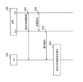
- FIG. 11 is a diagram illustrating an operation example of Solution 2 for reduction of service interruption.
- the CU (IAB-donor-CU) of the donor node 200 sends an RRC reconfiguration message to the IAB node 300, its child node 300-C, and its grandchild node 300-GC.
- this shows an example in which the IAB node 300, child node 300-C, and grandchild node 300-GC perform handover.
- the CU of the donor node 200 sends an RRC reconfiguration message before the handover of each IAB node 300, 300-C, and 300-GC is performed. Since the RRC reconfiguration message is sent to each IAB node 300, 300-C, and 300-GC in advance, it is easier to distribute the load compared to when the messages are sent all at once. can. Furthermore, load distribution makes it possible to reduce service interruptions to the UEs 100 under each of the IAB nodes 300, 300-C, and 300-GC.
- solution 2 is a solution in which execution of the RRC reconfiguration message is suspended in the IAB-MT of the child node.
- the IAB-MT of the child node receives an instruction from the DU of the parent node (that is, the IAB node) and starts executing the message.
- Solution 1 the transfer of the RRC reconfiguration message is suspended (or buffered) in the IAB-DU of the parent IAB node.
- Solution 1 when a certain condition is met, the pending message is sent.
- solution 2 the relationship between the mobile IAB node 300M and the UE 100 under its control is as follows, for example.
- the CU of the donor node 200 transmits an RRC reconfiguration message to the UE 100 under the mobile IAB node 300M. Then, the DU of the mobile IAB node 300M transmits an execution instruction ("Indication" shown in FIG. 11) to the UE 100. Upon receiving the execution instruction, the UE 100 starts executing the RRC reconfiguration message.
- the DU of the mobile IAB node 300M does not know at what timing to send the execution instruction ("Indication" shown in FIG. 11). If the transmission timing of the execution instruction is not appropriate, the UE 100 cannot properly connect to the target cell. Therefore, the UE 100 may not be able to properly connect to the network.
- the second embodiment aims to enable the UE 100 to appropriately connect to the network.
- the CU of the donor node 200 configures conditional reconfiguration for the UE 100, and then transmits an execution instruction transmission instruction to the mobile IAB node 300M.
- the mobile IAB node 300M then transmits an execution instruction to the UE 100 in response to receiving the transmission instruction.
- the UE 100 starts executing the conditional reconfiguration.
- a donor node receives an execution instruction and executes conditional reconfiguration including execution conditions on a user device under a mobile relay node (e.g. mobile IAB node 300M). (for example, UE 100).
- a mobile relay node e.g. mobile IAB node 300M
- the donor node transmits a transmission instruction to the mobile relay node instructing transmission of an execution instruction.
- the mobile relay node transmits an execution instruction to the user device in response to receiving the transmission instruction.
- the mobile IAB node 300M can receive a transmission instruction from the donor node 200 and transmit an execution instruction to the UE 100, so that the execution instruction can be transmitted to the UE 100 at an appropriate timing. . Therefore, it becomes possible for the UE 100 to execute conditional reconfiguration at an appropriate timing and perform handover to the target cell. Therefore, the UE 100 can appropriately connect to the network.
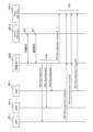
- FIG. 12 is a diagram illustrating an operation example according to the second embodiment.
- FIG. 12 shows an example in which the mobile IAB node 300M hands over from a source parent node (Source Parent) 300-S to a target parent node (Target Parent) 300-T. Further, FIG. 12 shows an example in which the subordinate UE 100 is also handed over in conjunction with the handover of the mobile IAB node 300M.
- the source parent node 300-S and the target parent node 300-T may be intermediate IAB nodes 300S under the donor node 200.
- step S20 the CU of the donor node 200 sets conditional reconfiguration to the UE 100.
- the CU of the donor node 200 generates an RRC message (for example, an RRC reconfiguration (HO command) message) that includes a conditional reconfiguration, and sends the F1 message that includes the RRRC message to the IAB-DU of the mobile IAB node 300M.
- RRC message for example, an RRC reconfiguration (HO command) message
- the IAB-DU of the mobile IAB node 300M extracts an RRC message including conditional reconfiguration from the F1 message and transmits the RRC message to the UE 100.
- the conditional reconfiguration may include multiple entries, with one setting being one entry. At least one of the plurality of entries includes an execution condition "to be executed in response to an execution instruction" (or “to be executed when an execution instruction is received”). As a result, the UE 100 does not start executing the execution condition even after receiving the conditional reconfiguration, but starts executing the execution condition upon receiving an execution instruction from the mobile IAB node 300M, as described above. The operation corresponding to solution 2 becomes possible.
- step S21 the CU of the donor node 200 transmits an execution instruction transmission instruction to the IAB-DU of the mobile IAB node 300M.
- the CU of the donor node 200 may generate an RRC message including a transmission instruction, and transmit the F1 message including the RRC message to the IAB-DU of the mobile IAB node 300M.
- the CU of donor node 200 may send an F1 message including a transmission instruction to the IAB-DU of mobile IAB node 300M.
- the transmission instruction may include the UE identifier of the UE 100 to which the transmission instruction is sent. Further, the transmission instruction may include a conditional reconfiguration identifier to which the transmission instruction is transmitted. The identifier represents, for example, information that instructs at least one of the plurality of conditional reconfigurations to be transmitted. Alternatively, the transmission instruction may include an entry number of a list in the conditional reconfiguration to which the transmission instruction is to be transmitted.
- the transmission instruction may include an instruction to immediately transmit the execution instruction.
- the transmission instruction may include an instruction to transmit an execution instruction when executing a conditional handover.
- the transmission instruction may include an instruction to transmit an execution instruction when performing handover.
- the transmission instruction may include an instruction to transmit an execution instruction when transmitting an RRC Reconfiguration Complete message.
- step S22 the IAB-DU of the mobile IAB node 300M transmits an execution instruction to the UE 100.
- the IAB-DU of the mobile IAB node 300M transmits an execution instruction for the conditional reconfiguration specified in the transmission instruction to the UE 100 specified in the transmission instruction (step S21).
- the execution instruction may be transmitted while being included in a MAC control element (MAC CE).
- the execution instruction may be included in a BAP Control PDU and transmitted.
- the execution instruction also includes a conditional reconfiguration identifier to be executed.
- the identifier represents, for example, information indicating at least one of the plurality of conditional reconfigurations to be executed.
- the execution instruction may include an entry number of a list in the conditional reconfiguration to be executed.
- step S23 the UE 100 executes the specified conditional reconfiguration and executes handover to the target cell.
- the mobile IAB node 300M has been described, but the present invention is not limited thereto.
- the intermediate IAB node 300S can be used instead of the mobile IAB node 300M.
- the UE 100 under the intermediate IAB node 300S executes conditional reconfiguration to change the target cell managed by the intermediate IAB node 300S (or other intermediate IAB node 300S) from the serving cell managed by the intermediate IAB node 300S. It becomes possible to execute handover to the managed target cell).
- the operation example shown in FIG. 12 can be implemented by replacing the mobile IAB node 300M with the intermediate IAB node 300S.
- conditional reconfiguration is set between the UE 100, the mobile IAB node 300M, and the donor node 200 has been described, but the present invention is not limited to this.
- conditional reconfiguration described in the second embodiment is also applicable between the UE 100 and the gNB 200.
- FIG. 13 is a diagram illustrating another example of operation according to the second embodiment.
- the CU of the gNB 200 sets conditional reconfiguration for the UE 100 similarly to the second embodiment (step S25).
- at least one of the entries included in the conditional reconfiguration includes the execution condition "to be executed according to an execution instruction.”
- the UE 100 does not immediately execute the conditional reconfiguration for the entry even if it is set, but waits until receiving an execution instruction.
- the CU of the gNB 200 transmits an execution instruction transmission instruction to the DU of the gNB 200 (step S26).
- the content of the transmission instruction and the information included in the transmission instruction may also be the same as in the second embodiment.
- the DU of the gNB 200 transmits an execution instruction to the UE 100 (step S27).
- the UE 100 starts the instructed execution condition and executes handover to the target cell, similarly to the second embodiment (step S28).
- a group handover is a handover performed simultaneously by a plurality of UEs 100 as one group.
- the mobile IAB node 300M is also included in the group and becomes a handover target.
- FIGS. 14A and 14B are diagrams illustrating an example of group handover operation according to the third embodiment.
- the source donor node (Source IAB-donor) 200-S sends an RRC retransmission command, which is a handover command, to each UE 100-1, ..., 100-n and the mobile IAB node 300M.
- RRC retransmission command which is a handover command
- the source donor node 200-S transmits a group reconfiguration message (including the F1 message) to the mobile IAB node 300M.
- the group reconfiguration message includes, for example, group handover configuration information.
- the group reconfiguration message is, for example, a message indicating a group handover instruction.
- the mobile IAB node 300M sends a group reconfiguration message to each UE 100-1, . . . , 100-n.
- group handover configuration information is transmitted from the source donor node 200-S to the mobile IAB node 300M using one F1 message.
- F1 message an individual message
- group handover can be set for multiple UEs 100-1, . . . , 100-n. Therefore, in the example shown in FIG. 14(B), the load of F1 signaling can be reduced compared to the example shown in FIG. 14(A).
- IAB since F1 signaling is also wireless, it is considered effective to reduce the load of F1 signaling compared to the case where it is performed by wire.
- the mobile IAB node 300M allows connection not only to the UE 100 dedicated to Rel-18 but also to the UE 100 compatible with Rel-17 or earlier. Therefore, at least, it is preferable that the mobile IAB node 300M transmits an RRC reconfiguration message that can be received even by the UE 100 of Rel-17 or earlier, rather than a new RRC reconfiguration message for group handover.
- the mobile IAB node 300M when the mobile IAB node 300M receives the common settings common to the group and the individual settings for each UE from the donor node, the mobile IAB node 300M combines them and creates an RRC that can also be received by the UE 100 of Rel-17 or earlier. An example of transmitting a reconfiguration message to each UE 100 will be described.
- a donor node for example, source donor node 200-S
- a mobile relay node for example, mobile IAB node 300M
- 1 message to the mobile relay node.
- the donor node sends a second message to the mobile relay node, including the individual settings of each user equipment under the mobile relay node.
- the mobile relay node sends an RRC reconfiguration message including common settings and individual settings to each user equipment.
- a message including a common setting can be used to set a common setting to the UEs 100 within the group. Therefore, compared to the case where each message is transmitted to each UE as shown in FIG. 14(A), in the second embodiment, it is possible to reduce F1 signaling.
- the message sent to the UE 100 uses an RRC reconfiguration message that can be received even by the UE 100 of Re-17 or earlier. Therefore, the UE 100 of Re-17 or earlier can also be appropriately connected to the target cell by group handover. Therefore, similarly to the first embodiment, the UE 100 can appropriately connect to the network.
- FIG. 15 is a diagram illustrating an operation example according to the third embodiment.
- the example shown in FIG. 15 represents an example in which the mobile IAB node 300M is handed over from the source donor node (Source IAB-donor) 200-S to the target donor node (Target IAB-donor) 200-T.
- the example shown in FIG. 14 represents an example in which the UEs 100-1, ..., 100-n under the mobile IAB node 300M also form one group and perform group handover in response to the handover of the mobile IAB node 300M.
- a group formed by a plurality of UEs 100-1, . . . , 100-n and in which group handover is performed may be referred to as a "UE group.”
- step S30 the CU of the source donor node 200-S transmits the common settings of the UE group to the IAB-DU of the mobile IAB node 300M.
- the CU of the source donor node 200-S may generate an RRC message (e.g., an RRC reconfiguration message) that includes a common configuration, and send an F1 message that includes the RRC message to the mobile IAB node 300M. .
- the CU of source donor node 200-S may send an F1 message containing the common settings to mobile IAB node 300M. In either case, the F1 message is an example of the first message.
- the common settings include settings common to the UEs 100-1, ..., 100-n belonging to the UE group.
- the setting may be the setting value itself.
- the settings may be represented as information elements (IEs).
- the message including the common settings may include a UE group identifier representing an identifier of the UE group.
- the message including the common settings may include a list of UE identifiers of the UEs 100 belonging to the UE group.
- a UE group identifier and/or a list of UE identifiers may be included in the common configuration.
- step S31 the CU of the source donor node 200-S transmits the individual settings of the UE group to the IAB-DU of the mobile IAB node 300M.
- the CU of the source donor node 200-S may generate an RRC message (e.g., an RRC reconfiguration message) including the personalized configuration, and send an F1 message including the RRC message to the mobile IAB node 300M.
- the CU of source donor node 200-S may send an F1 message containing personalized settings to mobile IAB node 300M.
- the F1 message is an example of the second message.
- the individual settings include individual settings for each UE 100-1, ..., 100-n belonging to the UE group.
- the setting may be the setting value itself.
- the settings may be represented as information elements (IEs).
- the message including the individual settings includes the UE identifier of the UE 100 belonging to the UE group.
- the UE identifier represents the UE 100 that is the target of individual settings.
- the UE identifier may be included in the individual settings.
- step S32 the IAB-DU of the mobile IAB node 300M combines the common settings and the individual settings, and generates an RRC reconfiguration message including the common settings and the individual settings.
- the RRC reconfiguration message is an RRC reconfiguration message that can also be received by the UE 100 of Rel-17 or earlier.
- the settings of the individual settings are given priority, so that the same settings are included in both the common settings and the individual settings. may be excluded from the list.
- the IAB-DU of the mobile IAB node 300M transmits the generated RRC reconfiguration message to each UE 100-1, ..., 100-n belonging to the UE group.
- step S33 the IAB-MT of the mobile IAB node 300M and each UE 100-1,..., 100-n transmit an RRC reconfiguration completion message to the target donor node (Target IAB-donor) 200-T. and complete the group handover.
- Target IAB-donor target donor node
- FIG. 16 is a diagram illustrating another example of operation according to the third embodiment.
- FIG. 16 shows an example in which UEs 100-1, ..., 100-n under gNB 200 form a UE group, and group handover is performed among the UEs 100-1, ..., 100-n.
- the CU of the gNB 200 transmits the common settings to the DU of the gNB 200 (step S35).
- the CU of the gNB 200 may generate an RRC message (for example, an RRC reconfiguration message) including the common settings, and transmit the F1 message including the RRC message to the DU of the gNB 200.
- the CU of the gNB 200 may transmit the F1 message including the common settings to the DU of the gNB 200, similarly to the third embodiment.
- the common settings themselves may be the same as in the third operation example.
- the CU of the gNB 200 transmits the individual settings to the DU of the gNB 200 (step S36).
- the CU of the gNB 200 may generate an RRC message (for example, an RRC reconfiguration message) including the individual settings, and transmit the F1 message including the RRC message to the DU of the gNB 200.
- the CU of the gNB 200 may transmit the F1 message including the individual settings to the DU of the gNB 200, similarly to the third embodiment.
- the individual settings themselves may be the same as in the third embodiment.
- the DU of the gNB 200 combines the common settings and the individual settings and transmits an RRC reconfiguration message including the common settings and the individual settings to each UE 100-1, ..., 100-n (step S38).
- the RRC reconfiguration message is an RRC reconfiguration message that can be received even in the UE 100 of Rel-17 or earlier.
- Each UE 100-1, . . . , 100-n transmits an RRC reconfiguration completion message to the target cell and completes the handover (step S38).
- a program that causes a computer to execute each process performed by the UE 100, gNB 200, or IAB node 300 may be provided.
- the program may be recorded on a computer readable medium.
- Computer-readable media allow programs to be installed on a computer.
- the computer-readable medium on which the program is recorded may be a non-transitory recording medium.
- the non-transitory recording medium is not particularly limited, but may be a recording medium such as a CD-ROM or a DVD-ROM.
- the circuits that execute each process performed by the UE 100, gNB 200, or IAB node 300 may be integrated, and at least a portion of the UE 100 or gNB 200 may be configured as a semiconductor integrated circuit (chip set, SoC: System on a chip). .
- the terms “based on” and “depending on” refer to “based solely on” and “depending solely on,” unless expressly stated otherwise. ” does not mean. Reference to “based on” means both “based solely on” and “based at least in part on.” Similarly, the phrase “in accordance with” means both “in accordance with” and “in accordance with, at least in part.” Furthermore, the terms “include” and “comprise” do not mean to include only the listed items, and may include only the listed items, or may include additional items in addition to the listed items. This means that it may include. Also, as used in this disclosure, the term “or” is not intended to be exclusive OR. Furthermore, any reference to elements using the designations "first,” “second,” etc.
- a communication control method used in a cellular communication system comprising: A communication control method comprising the step of a base station transmitting conditional reconfiguration including permission information indicating whether or not connection by RACHless handover is permitted for each target cell to a user equipment.
- the mobile relay node further comprises the step of transmitting combination information representing a combination of cells connectable by the RACHless handover to the donor node,
- the step of transmitting the conditional reconfiguration includes the step of the base station transmitting the conditional reconfiguration based on the combination information.
- the communication control method according to supplementary note 1 or supplementary note 2.
- a communication control method used in a cellular communication system comprising: a step in which the donor node transmits conditional reconfiguration including execution conditions to be executed upon receiving an execution instruction to a user device under the mobile relay node; the donor node transmitting a transmission instruction instructing transmission of the execution instruction to the mobile relay node; A communication control method, comprising the step of the mobile relay node transmitting the execution instruction to the user device in response to receiving the transmission instruction.
- the step of transmitting the execution instruction includes the step of the mobile relay node transmitting the execution instruction including information indicating whether at least one of the plurality of conditional reconfigurations should be executed. Including the communication control method described in Appendix 5.
- a communication control method used in a cellular communication system comprising: a donor node transmitting a first message including common settings common to a plurality of user devices under the mobile relay node to the mobile relay node; the donor node transmitting, to the mobile relay node, a second message including individual settings of each of the user equipments under the mobile relay node;
- a communication control method comprising the step of: the mobile relay node transmitting an RRC reconfiguration message including the common settings and the individual settings to each of the user equipments.
- the detailed objectives of this work item are as follows. - Define migration/topology adaptation procedures to enable mobility of IAB nodes. This also includes inter-donor migration (complete migration) of the entire mobile IAB node. - Enhance the mobility of IAB nodes and their served UEs. This includes aspects related to group mobility. There is no optimization targeted at surrounding UEs. Note: Solutions should not touch on topics that are already discussed in Rel-17 or have been excluded from Rel-17, except for enhancements specific to IAB node mobility. There is a need. - It is necessary to alleviate interference due to the mobility of IAB nodes, for example to avoid collisions of reference signals and control signals (PCI, RACH, etc.).
- PCI reference signals and control signals
- RAN3 and RAN2 will discuss the potential complications between scenarios where a mobile IAB node connects to a stationary (intermediate) IAB node and a scenario where a mobile IAB node connects directly to an IAB donor. It should be discussed.
- Group Reconfiguration Group UE mobility is expected as one of the possible enhancements of mobile IAB. This is because when a mobile IAB node moves to a new IAB donor, many UEs need to be handed over at the same time.
- handover is indicated by dedicated signaling, namely RRC reconfiguration and synchronization.
- RRC reconfiguration and synchronization.
- group reconfiguration may be considered as a candidate for reducing signaling overhead and delay. This is expected to reconfigure multiple UEs with one message.
- Proposal 2 Maintain the current CRRRC structure and do not advance a common RRC structure (i.e., no impact on RRCCR).
- RAN2 assumes that RRC will continue to use the dedicated UE configuration if agreed.
- F1 signal reduction is also more useful for mobile IAB than MBS, but since backhaul links are generally assumed on FR2, access link signal reduction is still more important.
- WID clearly states that ⁇ resolutions, except for improvements specific to IAB node mobility, do not address where Rel-17 discussions have already taken place and the topic has been excluded from Rel-17.'' RAN2 does not need to reopen group reconfiguration (or common RRC structure) in the Rel-18 mobile IAB, at least from RAN2's point of view.
- Proposal 1 The RAN2 should agree to only use individual RRC reconfiguration as is currently the case for UE handovers due to movement of mobile IAB nodes.
- RAN3 had two solutions for reducing service interruptions during donor-to-donor IAB node migration in Rel-17. Among them, solution 1 is shown in FIG.
- solution 1 the IAB-DU suspends the RRC reconfiguration message to the child node upon handover completion.
- RAN2 concluded that both solutions require further discussion, but determined that Solution 1 had less overall impact than Solution 2.
- the UE handover can also be performed without Solution 1.
- Solution 1 for intra-donor migration is reused to reduce service interruption for legacy UEs during inter-donor mobile IAB node migration.
- Proposal 2 RAN2 should assume that Solution 1 for reducing service interruption during Rel-17 intra-donor IAB node migration can be reused for legacy UE handover.
- Conditional Reconfiguration If individual RRC reconfigurations are sent to the UE simultaneously, many RRC messages and their corresponding responses may increase the radio resource load. Conditional reconfiguration is considered useful for load balancing, ie time domain distribution. This is so that the IAB donor can avoid sending many simultaneous messages by pre-reconfiguring the IAB node while the IAB donor is moving. There is a similar solution in Solution 2 for Rel-17 service interruption reduction.
- Conditional reconfiguration may help IAB donors distribute RRC reconfiguration messages in the time domain.
- the mobile IAB-DU may need to change its cell ID after the migration of the mobile IAB node. It will be done. For example, if the target topology requires changes to avoid PCI conflicts. In this case, the UE also needs to move from the old cell (the cell that disappears) to the new cell (the cell that becomes available), but both cells are managed by the same mobile IAB-DU. For such "cell shifts", conditional reconfiguration is considered more effective than conventional HO commands.
- conditional reconfiguration may work efficiently.
- Proposal 3 RAN2 should consider whether conditional reconfiguration to the UE can be enhanced for improved mobility of mobile IAB nodes.
- the UE must first initiate a random access procedure upon receiving the HO command.
- the target cell is the same as the source cell, ie, the same IAB-DU serves both cells, only the cell ID may be different.
- the timing advance is also the same in both cells, so no PRACH transmission is required.
- RAN2 should consider whether to specify RACH-less handover to improve the mobility of mobile IABs. Note that RACH-less handover applies only to Rel-18 UEs.
- Proposal 4 RAN2 should consider whether RACH-less handover of Rel-18 UE is useful due to the movement of mobile IAB nodes.
- the WID justification part states the assumption that "the mobile IAB node has no descendant IAB nodes, ie only serves UEs". Therefore, such an assumption should be confirmed by RAN2.
- Proposal 5 RAN2 should ensure that the mobile IAB node is always the access IAB node and therefore ensure that packet loss due to hop-by-hop ARQ is a rare case in Rel-18 mobile IAB. be.
- the UE's PDCP sublayer can handle data recovery as it does today. Therefore, no improvements are planned for lossless handover of UEs due to movement of mobile IAB nodes.
- Proposal 6 RAN2 should agree that the existing UE PDCP data recovery can be used in lossless handover due to movement of the mobile IAB node, i.e. no improvement is required.
- WID states that mobile IAB nodes only support UEs.
- a mobile IAB node has no child nodes, i.e. it needs to support only UEs.
- Proposal 7 RAN2 should agree to write in the Stage-2 specification that when acting as a mobile IAB node in this release, the IAB node should not set the IAB support IE in the SIB.
Landscapes
- Engineering & Computer Science (AREA)
- Computer Networks & Wireless Communication (AREA)
- Signal Processing (AREA)
- Mobile Radio Communication Systems (AREA)
Abstract
A communication control method according to an aspect is used in a cellular communication system. The communication control method comprises a step of a base station transmitting, to user equipment, a conditional reconfiguration that includes permission information indicating whether connection by RACH-less handover is permitted for each target cell.
Description
本開示は、セルラ通信システムに用いる通信制御方法に関する。
The present disclosure relates to a communication control method used in a cellular communication system.
セルラ通信システムの標準化プロジェクトである3GPP(Third Generation Partnership Project)において、IAB(Integrated Access and Backhaul)ノードと呼ばれる新たな中継ノードの導入が検討されている(例えば、非特許文献1参照)。1又は複数の中継ノードが、基地局とユーザ装置との間の通信に介在し、この通信に対する中継を行う。
In the 3GPP (Third Generation Partnership Project), which is a standardization project for cellular communication systems, the introduction of a new relay node called an IAB (Integrated Access and Backhaul) node is being considered (see, for example, Non-Patent Document 1). One or more relay nodes intervene in the communication between the base station and the user equipment and perform relaying for this communication.
第1の態様に係る通信制御方法は、セルラ通信システムで用いる通信制御方法である。前記通信制御方法は、基地局が、ユーザ装置に対して、ターゲットセル毎にRACHレスハンドオーバによる接続が許可されているか否かを表す許可情報を含む条件付き再設定を送信するステップを有する。
The communication control method according to the first aspect is a communication control method used in a cellular communication system. The communication control method includes the step of the base station transmitting conditional reconfiguration including permission information indicating whether or not connection by RACHless handover is permitted for each target cell to the user equipment.
第2の態様に係る通信制御方法は、セルラ通信システムで用いる通信制御方法である。前記通信制御方法は、ドナーノードが、実行指示を受けて実行する実行条件を含む条件付き再設定を、移動中継ノード配下のユーザ装置へ送信するステップを有する。また、前記通信制御方法は、ドナーノードが、実行指示の送信を指示する送信指示を、移動中継ノードへ送信するステップを有する。更に、前記通信制御方法は、移動中継ノードが、送信指示を受信したことに応じて、実行指示をユーザ装置へ送信するステップを有する。
The communication control method according to the second aspect is a communication control method used in a cellular communication system. The communication control method includes the step of the donor node transmitting conditional reconfiguration including an execution condition to be executed upon receiving an execution instruction to a user device under the mobile relay node. Further, the communication control method includes the step of the donor node transmitting a transmission instruction to the mobile relay node to instruct transmission of the execution instruction. Further, the communication control method includes the step of the mobile relay node transmitting an execution instruction to the user device in response to receiving the transmission instruction.
第3の態様に係る通信制御方法は、セルラ通信システムで用いる通信制御方法である。前記通信制御方法は、ドナーノードが、移動中継ノード配下の複数のユーザ装置に共通する共通設定を含む第1メッセージを移動中継ノードへ送信するステップを有する。また、前記通信制御方法は、ドナーノードが、移動中継ノード配下の各ユーザ装置の個別設定を含む第2メッセージを移動中継ノードへ送信するステップを有する。更に、前記通信制御方法は、移動中継ノードが、共通設定と個別設定とを含むRRC再設定メッセージを各ユーザ装置へ送信するステップを有する。
The communication control method according to the third aspect is a communication control method used in a cellular communication system. The communication control method includes the step of the donor node transmitting to the mobile relay node a first message including common settings common to a plurality of user devices under the mobile relay node. The communication control method also includes the step of the donor node transmitting a second message including individual settings of each user device under the mobile relay node to the mobile relay node. Further, the communication control method includes the step of the mobile relay node transmitting an RRC reconfiguration message including common settings and individual settings to each user equipment.
図面を参照しながら、実施形態に係るセルラ通信システムについて説明する。図面の記載において、同一又は類似の部分には同一又は類似の符号を付している。
A cellular communication system according to an embodiment will be described with reference to the drawings. In the description of the drawings, the same or similar parts are designated by the same or similar symbols.
[第1実施形態]
(セルラ通信システムの構成)
一実施形態に係るセルラ通信システムの構成例について説明する。一実施形態に係るセルラ通信システム1は3GPPの5Gシステムである。具体的には、セルラ通信システム1における無線アクセス方式は、5Gの無線アクセス方式であるNR(New Radio)である。但し、セルラ通信システム1には、LTE(Long Term Evolution)が少なくとも部分的に適用されてもよい。また、セルラ通信システム1は、6Gなど、将来のセルラ通信システムも適用されてよい。 [First embodiment]
(Configuration of cellular communication system)
A configuration example of a cellular communication system according to an embodiment will be described. Thecellular communication system 1 according to one embodiment is a 3GPP 5G system. Specifically, the radio access method in the cellular communication system 1 is NR (New Radio), which is a 5G radio access method. However, LTE (Long Term Evolution) may be applied at least partially to the cellular communication system 1. Moreover, future cellular communication systems such as 6G may also be applied to the cellular communication system 1.
(セルラ通信システムの構成)
一実施形態に係るセルラ通信システムの構成例について説明する。一実施形態に係るセルラ通信システム1は3GPPの5Gシステムである。具体的には、セルラ通信システム1における無線アクセス方式は、5Gの無線アクセス方式であるNR(New Radio)である。但し、セルラ通信システム1には、LTE(Long Term Evolution)が少なくとも部分的に適用されてもよい。また、セルラ通信システム1は、6Gなど、将来のセルラ通信システムも適用されてよい。 [First embodiment]
(Configuration of cellular communication system)
A configuration example of a cellular communication system according to an embodiment will be described. The
図1は、一実施形態に係るセルラ通信システム1の構成例を示す図である。
FIG. 1 is a diagram showing a configuration example of a cellular communication system 1 according to an embodiment.
図1に示すように、セルラ通信システム1は、5Gコアネットワーク(5GC)10と、ユーザ装置(UE:User Equipment)100、基地局装置(以下、「基地局」と称する場合がある。)200-1,200-2、及びIABノード300-1,300-2を有する。基地局200は、gNBと呼ばれる場合がある。
As shown in FIG. 1, the cellular communication system 1 includes a 5G core network (5GC) 10, a user equipment (UE) 100, and a base station device (hereinafter sometimes referred to as "base station") 200. -1, 200-2, and IAB nodes 300-1, 300-2. Base station 200 may be called a gNB.
以下において、基地局200がNR基地局である一例について主として説明するが、基地局200がLTE基地局(すなわち、eNB)であってもよい。
Although an example in which the base station 200 is an NR base station will be mainly described below, the base station 200 may be an LTE base station (i.e., an eNB).
なお、以下において、基地局200-1,200-2をgNB200(又は基地局200)、IABノード300-1,300-2をIABノード300とそれぞれ称する場合がある。
Note that hereinafter, the base stations 200-1 and 200-2 may be referred to as gNB 200 (or base station 200), and the IAB nodes 300-1 and 300-2 may be referred to as IAB node 300, respectively.
5GC10は、AMF(Access and Mobility Management Function)11及びUPF(User Plane Function)12を有する。AMF11は、UE100に対する各種モビリティ制御等を行う装置である。AMF11は、NAS(Non-Access Stratum)シグナリングを用いてUE100と通信することにより、UE100が在圏するエリアの情報を管理する。UPF12は、ユーザデータの転送制御等を行う装置である。
The 5GC 10 has an AMF (Access and Mobility Management Function) 11 and a UPF (User Plane Function) 12. The AMF 11 is a device that performs various mobility controls for the UE 100. The AMF 11 manages information about the area where the UE 100 is located by communicating with the UE 100 using NAS (Non-Access Stratum) signaling. The UPF 12 is a device that controls the transfer of user data.
各gNB200は、固定の無線通信ノードであって、1又は複数のセルを管理する。セルは、無線通信エリアの最小単位を示す用語として用いられる。セルは、UE100との無線通信を行う機能又はリソースを示す用語として用いられることがある。1つのセルは1つのキャリア周波数に属する。以下では、セルと基地局とを区別しないで用いる場合がある。
Each gNB 200 is a fixed wireless communication node and manages one or more cells. A cell is a term used to indicate the smallest unit of a wireless communication area. A cell is sometimes used as a term indicating a function or resource for performing wireless communication with the UE 100. One cell belongs to one carrier frequency. In the following, cells and base stations may be used without distinction.
各gNB200は、NGインターフェイスと呼ばれるインターフェイスを介して5GC10と相互に接続される。図1において、5GC10に接続された2つのgNB200-1及びgNB200-2を例示している。
Each gNB 200 is interconnected with the 5GC 10 via an interface called an NG interface. In FIG. 1, two gNB200-1 and gNB200-2 connected to 5GC10 are illustrated.
各gNB200は、集約ユニット(CU:Central Unit)と分散ユニット(DU:Distributed Unit)とに分割されていてもよい。CU及びDUは、F1インターフェイスと呼ばれるインターフェイスを介して相互に接続される。F1プロトコルは、CUとDUとの間の通信プロトコルであって、制御プレーンのプロトコルであるF1-CプロトコルとユーザプレーンのプロトコルであるF1-Uプロトコルとがある。
Each gNB 200 may be divided into a central unit (CU) and a distributed unit (DU). CU and DU are interconnected via an interface called F1 interface. The F1 protocol is a communication protocol between the CU and DU, and includes the F1-C protocol, which is a control plane protocol, and the F1-U protocol, which is a user plane protocol.
セルラ通信システム1は、バックホールにNRを用いてNRアクセスの無線中継を可能とするIABをサポートする。ドナーgNB200-1(又はドナーノード。以下、「ドナーノード」と称する場合がある。)は、ネットワーク側のNRバックホールの終端ノードであり、IABをサポートする追加機能を備えたドナー基地局である。バックホールは、複数のホップ(すなわち、複数のIABノード300)を介するマルチホップが可能である。
The cellular communication system 1 supports IAB that uses NR for backhaul and enables wireless relay of NR access. The donor gNB 200-1 (or donor node, hereinafter sometimes referred to as "donor node") is a terminal node of the NR backhaul on the network side, and is a donor base station equipped with additional functions to support IAB. . The backhaul can be multi-hop through multiple hops (ie, multiple IAB nodes 300).
図1において、IABノード300-1がドナーノード200-1と無線で接続し、IABノード300-2がIABノード300-1と無線で接続し、F1プロトコルが2つのバックホールホップで伝送される一例を示している。
In FIG. 1, IAB node 300-1 is wirelessly connected to donor node 200-1, IAB node 300-2 is wirelessly connected to IAB node 300-1, and the F1 protocol is transmitted over two backhaul hops. An example is shown.
UE100は、セルとの無線通信を行う移動可能な無線通信装置である。UE100は、gNB200又はIABノード300との無線通信を行う装置であればどのような装置であってもよい。例えば、UE100は、携帯電話端末及び/又はタブレット端末、ノートPC、センサ若しくはセンサに設けられる装置、車両若しくは車両に設けられる装置、飛行体若しくは飛行体に設けられる装置である。UE100は、アクセスリンクを介してIABノード300又はgNB200に無線で接続する。図1において、UE100がIABノード300-2と無線で接続される一例を示している。UE100は、IABノード300-2及びIABノード300-1を介してドナーノード200-1と間接的に通信する。
The UE 100 is a mobile wireless communication device that performs wireless communication with a cell. The UE 100 may be any device that performs wireless communication with the gNB 200 or the IAB node 300. For example, the UE 100 is a mobile phone terminal and/or a tablet terminal, a notebook PC, a sensor or a device provided on the sensor, a vehicle or a device provided on the vehicle, an aircraft, or a device provided on the aircraft. UE 100 wirelessly connects to IAB node 300 or gNB 200 via an access link. FIG. 1 shows an example in which the UE 100 is wirelessly connected to the IAB node 300-2. UE 100 indirectly communicates with donor node 200-1 via IAB node 300-2 and IAB node 300-1.
図2は、IABノード300と親ノード(Parent nodes)と子ノード(Child nodes)との関係例を示す図である。
FIG. 2 is a diagram showing an example of the relationship between the IAB node 300, parent nodes, and child nodes.
図2に示すように、各IABノード300は、基地局機能部に相当するIAB-DUとユーザ装置機能部に相当するIAB-MT(Mobile Termination)とを有する。
As shown in FIG. 2, each IAB node 300 has an IAB-DU that corresponds to a base station function unit and an IAB-MT (Mobile Termination) that corresponds to a user equipment function unit.
IAB-MTのNR Uu無線インターフェイス上の隣接ノード(すなわち、上位ノード)は、親ノードと呼ばれる。親ノードは、親IABノード又はドナーノード200のDUである。IAB-MTと親ノードとの間の無線リンクは、バックホールリンク(BHリンク)と呼ばれる。図2において、IABノード300の親ノードがIABノード300-P1及び300-P2である一例を示している。なお、親ノードへ向かう方向は、アップストリーム(upstream)と呼ばれる。UE100から見て、UE100の上位ノードは親ノードに該当し得る。
The adjacent node (ie, the upper node) on the NR Uu radio interface of the IAB-MT is called the parent node. The parent node is the DU of the parent IAB node or donor node 200. The wireless link between the IAB-MT and the parent node is called the backhaul link (BH link). FIG. 2 shows an example in which the parent nodes of the IAB node 300 are IAB nodes 300-P1 and 300-P2. Note that the direction toward the parent node is called upstream. Seen from the UE 100, a higher-order node of the UE 100 may correspond to a parent node.
IAB-DUのNRアクセスインターフェイス上の隣接ノード(すなわち、下位ノード)は、子ノードと呼ばれる。IAB-DUは、gNB200と同様に、セルを管理する。IAB-DUは、UE100及び下位のIABノードへのNR Uu無線インターフェイスを終端する。IAB-DUは、ドナーノード200-1のCUへのF1プロトコルをサポートする。図2において、IABノード300の子ノードがIABノード300-C1~300-C3である一例を示しているが、IABノード300の子ノードにUE100が含まれてもよい。なお、子ノードへ向かう方向は、ダウンストリーム(downstream)と呼ばれる。
Adjacent nodes (ie, subordinate nodes) on the NR access interface of the IAB-DU are called child nodes. The IAB-DU manages cells in the same way as the gNB 200. The IAB-DU terminates the NR Uu radio interface to the UE 100 and lower IAB nodes. IAB-DU supports the F1 protocol to the CU of donor node 200-1. Although FIG. 2 shows an example in which the child nodes of the IAB node 300 are the IAB nodes 300-C1 to 300-C3, the child nodes of the IAB node 300 may include the UE 100. Note that the direction toward the child node is called downstream.
また、1つ又は複数のホップを介して、ドナーノード200に接続されている全てのIABノード300は、ドナーノード200をルートとする有向非巡回グラフ(DAG:Directed Acyclic Graph)トポロジ(以下、「トポロジ」と称する場合がある。)を形成する。このトポロジにおいて、図2に示すように、IAB-DUのインターフェイス上の隣り合うノードが子ノード、IAB-MTのインターフェイス上の隣り合うノードが親ノードとなる。ドナーノード200は、例えば、IABトポロジのリソース、トポロジ、ルート管理などを集中的に行う。ドナーノード200は、バックホールリンクとアクセスリンクのネットワークを介して、UE100に対して、ネットワークアクセスを提供するgNBである。
In addition, all IAB nodes 300 connected to the donor node 200 via one or more hops have a directed acyclic graph (DAG) topology (hereinafter referred to as (sometimes referred to as a "topology"). In this topology, as shown in FIG. 2, adjacent nodes on the IAB-DU interface are child nodes, and adjacent nodes on the IAB-MT interface are parent nodes. The donor node 200 centrally manages, for example, the resources, topology, and routes of the IAB topology. Donor node 200 is a gNB that provides network access to UE 100 via a network of backhaul links and access links.
(基地局の構成)
次に、実施形態に係る基地局であるgNB200の構成について説明する。図3は、gNB200の構成例を示す図である。図3に示すように、gNB200は、無線通信部210と、ネットワーク通信部220と、制御部230とを有する。 (Base station configuration)
Next, the configuration ofgNB 200, which is the base station according to the embodiment, will be described. FIG. 3 is a diagram showing a configuration example of the gNB 200. As shown in FIG. 3, the gNB 200 includes a wireless communication section 210, a network communication section 220, and a control section 230.
次に、実施形態に係る基地局であるgNB200の構成について説明する。図3は、gNB200の構成例を示す図である。図3に示すように、gNB200は、無線通信部210と、ネットワーク通信部220と、制御部230とを有する。 (Base station configuration)
Next, the configuration of
無線通信部210は、UE100との無線通信及びIABノード300との無線通信を行う。無線通信部210は、受信部211及び送信部212を有する。受信部211は、制御部230の制御下で各種の受信を行う。受信部211はアンテナを含み、アンテナが受信する無線信号をベースバンド信号(受信信号)に変換(ダウンコンバート)して制御部230に出力する。送信部212は、制御部230の制御下で各種の送信を行う。送信部212はアンテナを含み、制御部230が出力するベースバンド信号(送信信号)を無線信号に変換(アップコンバート)してアンテナから送信する。
The wireless communication unit 210 performs wireless communication with the UE 100 and the IAB node 300. The wireless communication section 210 includes a receiving section 211 and a transmitting section 212. The receiving unit 211 performs various types of reception under the control of the control unit 230. Receiving section 211 includes an antenna, converts (down converts) a radio signal received by the antenna into a baseband signal (received signal), and outputs the baseband signal (received signal) to control section 230 . The transmitter 212 performs various types of transmission under the control of the controller 230. The transmitter 212 includes an antenna, converts (up-converts) the baseband signal (transmission signal) output by the controller 230 into a wireless signal, and transmits it from the antenna.
ネットワーク通信部220は、5GC10との有線通信(又は無線通信)及び隣接する他のgNB200との有線通信(又は無線通信)を行う。ネットワーク通信部220は、受信部221及び送信部222を有する。受信部221は、制御部230の制御下で各種の受信を行う。受信部221は、外部から信号を受信して受信信号を制御部230に出力する。送信部222は、制御部230の制御下で各種の送信を行う。送信部222は、制御部230が出力する送信信号を外部に送信する。
The network communication unit 220 performs wired communication (or wireless communication) with the 5GC 10 and wired communication (or wireless communication) with other adjacent gNBs 200. The network communication section 220 includes a receiving section 221 and a transmitting section 222. The receiving unit 221 performs various types of reception under the control of the control unit 230. The receiving section 221 receives a signal from the outside and outputs the received signal to the control section 230. The transmitter 222 performs various types of transmission under the control of the controller 230. The transmitter 222 transmits the transmit signal output by the controller 230 to the outside.
制御部230は、gNB200における各種の制御を行う。制御部230は、少なくとも1つのメモリと、メモリと電気的に接続された少なくとも1つのプロセッサとを含む。メモリは、プロセッサにより実行されるプログラム、及びプロセッサによる処理に用いられる情報を記憶する。プロセッサは、ベースバンドプロセッサとCPUとを含んでもよい。ベースバンドプロセッサは、ベースバンド信号の変調・復調及び符号化・復号等を行う。CPUは、メモリに記憶されるプログラムを実行して各種の処理を行う。プロセッサは、後述する各レイヤの処理を行う。なお、制御部230は、以下に示す各実施形態において、gNB200における各処理又は各動作を行ってもよい。
The control unit 230 performs various controls in the gNB 200. Control unit 230 includes at least one memory and at least one processor electrically connected to the memory. The memory stores programs executed by the processor and information used in processing by the processor. The processor may include a baseband processor and a CPU. The baseband processor performs modulation/demodulation, encoding/decoding, etc. of the baseband signal. The CPU executes programs stored in memory to perform various processes. The processor processes each layer, which will be described later. Note that the control unit 230 may perform each process or each operation in the gNB 200 in each embodiment described below.
(中継ノードの構成)
次に、実施形態に係る中継ノード(又は中継ノード装置。以下、「中継ノード」と称する場合がある。)であるIABノード300の構成について説明する。図4は、IABノード300の構成例を示す図である。図4に示すように、IABノード300は、無線通信部310と、制御部320とを有する。IABノード300は、無線通信部310を複数有していてもよい。 (Relay node configuration)
Next, the configuration of theIAB node 300, which is a relay node (or relay node device; hereinafter sometimes referred to as "relay node") according to the embodiment will be described. FIG. 4 is a diagram showing a configuration example of the IAB node 300. As shown in FIG. 4, the IAB node 300 includes a wireless communication section 310 and a control section 320. The IAB node 300 may have a plurality of wireless communication units 310.
次に、実施形態に係る中継ノード(又は中継ノード装置。以下、「中継ノード」と称する場合がある。)であるIABノード300の構成について説明する。図4は、IABノード300の構成例を示す図である。図4に示すように、IABノード300は、無線通信部310と、制御部320とを有する。IABノード300は、無線通信部310を複数有していてもよい。 (Relay node configuration)
Next, the configuration of the
無線通信部310は、gNB200との無線通信(BHリンク)及びUE100との無線通信(アクセスリンク)を行う。BHリンク通信用の無線通信部310とアクセスリンク通信用の無線通信部310とが別々に設けられていてもよい。
The wireless communication unit 310 performs wireless communication with the gNB 200 (BH link) and wireless communication with the UE 100 (access link). The wireless communication unit 310 for BH link communication and the wireless communication unit 310 for access link communication may be provided separately.
無線通信部310は、受信部311及び送信部312を有する。受信部311は、制御部320の制御下で各種の受信を行う。受信部311はアンテナを含み、アンテナが受信する無線信号をベースバンド信号(受信信号)に変換(ダウンコンバート)して制御部320に出力する。送信部312は、制御部320の制御下で各種の送信を行う。送信部312はアンテナを含み、制御部320が出力するベースバンド信号(送信信号)を無線信号に変換(アップコンバート)してアンテナから送信する。
The wireless communication section 310 includes a receiving section 311 and a transmitting section 312. The receiving unit 311 performs various types of reception under the control of the control unit 320. Receiving section 311 includes an antenna, converts (down converts) a radio signal received by the antenna into a baseband signal (received signal), and outputs the baseband signal (received signal) to control section 320 . The transmitter 312 performs various types of transmission under the control of the controller 320. The transmitter 312 includes an antenna, converts (up-converts) the baseband signal (transmission signal) output by the controller 320 into a wireless signal, and transmits it from the antenna.
制御部320は、IABノード300における各種の制御を行う。制御部320は、少なくとも1つのメモリと、メモリと電気的に接続された少なくとも1つのプロセッサとを含む。メモリは、プロセッサにより実行されるプログラム、及びプロセッサによる処理に用いられる情報を記憶する。プロセッサは、ベースバンドプロセッサ及びCPUを含んでもよい。ベースバンドプロセッサは、ベースバンド信号の変調・復調及び符号化・復号等を行う。CPUは、メモリに記憶されるプログラムを実行して各種の処理を行う。プロセッサは、後述する各レイヤの処理を行う。なお、制御部320は、以下に示す各実施形態において、IABノード300における各処理又は各動作を行ってもよい。
The control unit 320 performs various controls in the IAB node 300. Control unit 320 includes at least one memory and at least one processor electrically connected to the memory. The memory stores programs executed by the processor and information used in processing by the processor. The processor may include a baseband processor and a CPU. The baseband processor performs modulation/demodulation, encoding/decoding, etc. of the baseband signal. The CPU executes programs stored in memory to perform various processes. The processor processes each layer, which will be described later. Note that the control unit 320 may perform each process or each operation in the IAB node 300 in each embodiment described below.
(ユーザ装置の構成)
次に、実施形態に係るユーザ装置であるUE100の構成について説明する。図5は、UE100の構成例を示す図である。図5に示すように、UE100は、無線通信部110と、制御部120とを有する。 (Configuration of user device)
Next, the configuration of theUE 100, which is the user device according to the embodiment, will be described. FIG. 5 is a diagram showing a configuration example of the UE 100. As shown in FIG. 5, UE 100 includes a wireless communication section 110 and a control section 120.
次に、実施形態に係るユーザ装置であるUE100の構成について説明する。図5は、UE100の構成例を示す図である。図5に示すように、UE100は、無線通信部110と、制御部120とを有する。 (Configuration of user device)
Next, the configuration of the
無線通信部110は、アクセスリンクにおける無線通信、すなわち、gNB200との無線通信及びIABノード300との無線通信を行う。また、無線通信部110は、サイドリンクにおける無線通信、すなわち、他のUE100との無線通信を行ってもよい。無線通信部110は、受信部111及び送信部112を有する。受信部111は、制御部120の制御下で各種の受信を行う。受信部111はアンテナを含み、アンテナが受信する無線信号をベースバンド信号(受信信号)に変換(ダウンコンバート)して制御部120に出力する。送信部112は、制御部120の制御下で各種の送信を行う。送信部112はアンテナを含み、制御部120が出力するベースバンド信号(送信信号)を無線信号に変換(アップコンバート)してアンテナから送信する。
The wireless communication unit 110 performs wireless communication on the access link, that is, wireless communication with the gNB 200 and wireless communication with the IAB node 300. Furthermore, the wireless communication unit 110 may perform sidelink wireless communication, that is, wireless communication with other UEs 100. The wireless communication section 110 includes a receiving section 111 and a transmitting section 112. The receiving unit 111 performs various types of reception under the control of the control unit 120. Receiving section 111 includes an antenna, converts (down converts) a radio signal received by the antenna into a baseband signal (received signal), and outputs the baseband signal (received signal) to control section 120 . The transmitter 112 performs various types of transmission under the control of the controller 120. The transmitter 112 includes an antenna, converts (up-converts) the baseband signal (transmission signal) output by the controller 120 into a wireless signal, and transmits it from the antenna.
制御部120は、UE100における各種の制御を行う。制御部120は、少なくとも1つのメモリと、メモリと電気的に接続された少なくとも1つのプロセッサとを含む。メモリは、プロセッサにより実行されるプログラム、及びプロセッサによる処理に用いられる情報を記憶する。プロセッサは、ベースバンドプロセッサ及びCPUを含んでもよい。ベースバンドプロセッサは、ベースバンド信号の変調・復調及び符号化・復号等を行う。CPUは、メモリに記憶されるプログラムを実行して各種の処理を行う。プロセッサは、後述する各レイヤの処理を行う。なお、制御部120は、以下に示す各実施形態において、UE100における各処理を行うようにしてもよい。
The control unit 120 performs various controls in the UE 100. Control unit 120 includes at least one memory and at least one processor electrically connected to the memory. The memory stores programs executed by the processor and information used in processing by the processor. The processor may include a baseband processor and a CPU. The baseband processor performs modulation/demodulation, encoding/decoding, etc. of the baseband signal. The CPU executes programs stored in memory to perform various processes. The processor processes each layer, which will be described later. Note that the control unit 120 may perform each process in the UE 100 in each embodiment described below.
(プロトコルスタックの構成)
次に、実施形態に係るプロトコルスタックの構成について説明する。図6は、IAB-MTのRRC接続及びNAS接続に関するプロトコルスタックの例を示す図である。 (Protocol stack configuration)
Next, the configuration of the protocol stack according to the embodiment will be explained. FIG. 6 is a diagram illustrating an example of a protocol stack regarding RRC connection and NAS connection of IAB-MT.
図6に示すように、IABノード300-2のIAB-MTは、物理(PHY)レイヤと、MAC(Medium Access Control)レイヤと、RLC(Radio Link Control)レイヤと、PDCP(Packet Data Convergence Protocol)レイヤと、RRC(Radio Resource Control)レイヤと、NAS(Non-Access Stratum)レイヤとを有する。
As shown in FIG. 6, the IAB-MT of the IAB node 300-2 includes a physical (PHY) layer, a MAC (Medium Access Control) layer, an RLC (Radio Link Control) layer, and a PDCP (Packet Data Convergence Protocol) layer. layer, an RRC (Radio Resource Control) layer, and a NAS (Non-Access Stratum) layer.
PHYレイヤは、符号化・復号、変調・復調、アンテナマッピング・デマッピング、及びリソースマッピング・デマッピングを行う。IABノード300-2のIAB-MTのPHYレイヤとIABノード300-1のIAB-DUのPHYレイヤとの間では、物理チャネルを介してデータ及び制御情報が伝送される。
The PHY layer performs encoding/decoding, modulation/demodulation, antenna mapping/demapping, and resource mapping/demapping. Data and control information are transmitted between the PHY layer of the IAB-MT of the IAB node 300-2 and the PHY layer of the IAB-DU of the IAB node 300-1 via a physical channel.
MACレイヤは、データの優先制御、ハイブリッドARQ(HARQ:Hybrid Automatic Repeat reQuest)による再送処理、及びランダムアクセスプロシージャ等を行う。IABノード300-2のIAB-MTのMACレイヤとIABノード300-1のIAB-DUのMACレイヤとの間では、トランスポートチャネルを介してデータ及び制御情報が伝送される。IAB-DUのMACレイヤはスケジューラを含む。スケジューラは、上下リンクのトランスポートフォーマット(トランスポートブロックサイズ、変調・符号化方式(MCS:Modulation and Coding Scheme))及び割当リソースブロックを決定する。
The MAC layer performs data priority control, retransmission processing using Hybrid ARQ (HARQ: Hybrid Automatic Repeat reQuest), random access procedure, etc. Data and control information are transmitted between the IAB-MT MAC layer of IAB node 300-2 and the IAB-DU MAC layer of IAB node 300-1 via a transport channel. The IAB-DU MAC layer includes a scheduler. The scheduler determines uplink and downlink transport formats (transport block size, modulation and coding scheme (MCS)) and allocated resource blocks.
RLCレイヤは、MACレイヤ及びPHYレイヤの機能を利用してデータを受信側のRLCレイヤに伝送する。IABノード300-2のIAB-MTのRLCレイヤとIABノード300-1のIAB-DUのRLCレイヤとの間では、論理チャネルを介してデータ及び制御情報が伝送される。
The RLC layer uses the functions of the MAC layer and PHY layer to transmit data to the RLC layer on the receiving side. Data and control information are transmitted between the RLC layer of the IAB-MT of the IAB node 300-2 and the RLC layer of the IAB-DU of the IAB node 300-1 via logical channels.
PDCPレイヤは、ヘッダ圧縮・伸張、及び暗号化・復号化を行う。IABノード300-2のIAB-MTのPDCPレイヤとドナーノード200のPDCPレイヤとの間では、無線ベアラを介してデータ及び制御情報が伝送される。
The PDCP layer performs header compression/expansion, and encryption/decryption. Data and control information are transmitted between the PDCP layer of the IAB-MT of the IAB node 300-2 and the PDCP layer of the donor node 200 via radio bearers.
RRCレイヤは、無線ベアラの確立、再確立及び解放に応じて、論理チャネル、トランスポートチャネル、及び物理チャネルを制御する。IABノード300-2のIAB-MTのRRCレイヤとドナーノード200のRRCレイヤとの間では、各種設定のためのRRCシグナリングが伝送される。ドナーノード200とのRRC接続がある場合、IAB-MTはRRCコネクティッド状態である。ドナーノード200とのRRC接続がない場合、IAB-MTはRRCアイドル状態である。
The RRC layer controls logical channels, transport channels and physical channels according to the establishment, re-establishment and release of radio bearers. RRC signaling for various settings is transmitted between the IAB-MT RRC layer of IAB node 300-2 and the RRC layer of donor node 200. If there is an RRC connection with the donor node 200, the IAB-MT is in the RRC connected state. If there is no RRC connection with donor node 200, IAB-MT is in RRC idle state.
RRCレイヤの上位に位置するNASレイヤは、セッション管理及びモビリティ管理等を行う。IABノード300-2のIAB-MTのNASレイヤとAMF11との間では、NASシグナリングが伝送される。
The NAS layer located above the RRC layer performs session management, mobility management, etc. NAS signaling is transmitted between the NAS layer of the IAB-MT of the IAB node 300-2 and the AMF 11.
図7は、F1-Uプロトコルに関するプロトコルスタックを示す図である。図8は、F1-Cプロトコルに関するプロトコルスタックを示す図である。ここでは、ドナーノード200がCU及びDUに分割されている一例を示す。
FIG. 7 is a diagram showing a protocol stack regarding the F1-U protocol. FIG. 8 is a diagram showing a protocol stack regarding the F1-C protocol. Here, an example is shown in which the donor node 200 is divided into a CU and a DU.
図7に示すように、IABノード300-2のIAB-MT、IABノード300-1のIAB-DU、IABノード300-1のIAB-MT、及びドナーノード200のDUの各々は、RLCレイヤの上位レイヤとしてBAP(Backhaul Adaptation Protocol)レイヤを有する。BAPレイヤは、ルーティング処理及びベアラマッピング・デマッピング処理を行うレイヤである。バックホールでは、IPレイヤがBAPレイヤを介して伝送されることにより、複数のホップでのルーティングが可能になる。
As shown in FIG. 7, each of the IAB-MT of the IAB node 300-2, the IAB-DU of the IAB node 300-1, the IAB-MT of the IAB node 300-1, and the DU of the donor node 200 is configured in the RLC layer. It has a BAP (Backhaul Adaptation Protocol) layer as an upper layer. The BAP layer is a layer that performs routing processing and bearer mapping/demapping processing. In backhaul, the IP layer is transmitted through the BAP layer, allowing multi-hop routing.
各バックホールリンクにおいて、BAPレイヤのPDU(Protocol Data Unit)は、バックホールRLCチャネル(BH NR RLCチャネル)によって伝送される。各BHリンクで複数のバックホールRLCチャネルを構成することにより、トラフィックの優先順位付け及びQoS(Quality of Service)制御が可能である。BAP PDUとバックホールRLCチャネルとの対応付けは、各IABノード300のBAPレイヤ及びドナーノード200のBAPレイヤによって実行される。
In each backhaul link, BAP layer PDUs (Protocol Data Units) are transmitted by a backhaul RLC channel (BH NR RLC channel). By configuring multiple backhaul RLC channels on each BH link, traffic prioritization and QoS (Quality of Service) control are possible. The association between BAP PDUs and backhaul RLC channels is performed by the BAP layer of each IAB node 300 and the BAP layer of the donor node 200.
図8に示すように、F1-Cプロトコルのプロトコルスタックは、図7に示すGTP-Uレイヤ及びUDPレイヤに代えて、F1APレイヤ及びSCTPレイヤを有する。
As shown in FIG. 8, the protocol stack of the F1-C protocol has an F1AP layer and an SCTP layer instead of the GTP-U layer and UDP layer shown in FIG.
なお、以下においては、IABのIAB-DUとIAB-MTで行われる処理又は動作について、単に「IAB」の処理又は動作として説明する場合がある。例えば、IABノード300-1のIAB-DUが、IABノード300-2のIAB-MTへBAPレイヤのメッセージを送信することを、IABノード300-1がIABノード300-2へ、当該メッセージを送信するものとして説明する。また、ドナーノード200のDU又はCUの処理又は動作についても、単に「ドナーノード」の処理又は動作として説明する場合がある。
Note that hereinafter, the processing or operation performed by IAB-DU and IAB-MT of IAB may be simply described as "IAB" processing or operation. For example, if the IAB-DU of the IAB node 300-1 sends a BAP layer message to the IAB-MT of the IAB node 300-2, the IAB node 300-1 sends the message to the IAB node 300-2. I will explain it as something that does. Furthermore, the processing or operation of the DU or CU of the donor node 200 may also be simply described as the processing or operation of the "donor node."
また、アップストリーム方向とアップリンク(UL)方向とを区別しないで用いる場合がある。更に、ダウンストリーム方向とダウンリンク(DL)方向とを区別しないで用いる場合がある。
Furthermore, the upstream direction and the uplink (UL) direction may be used without distinguishing between them. Furthermore, the downstream direction and the downlink (DL) direction may be used interchangeably.
(移動IABノード)
現在、3GPPでは、移動IABノード(mobile IAB node)の導入に向けた検討が開始されている。移動IABノードとは、例えば、移動しているIABノードである。移動IABノードは、移動可能なIABノードであってもよい。或いは、移動IABノードは、移動する能力を有するIABノードであってもよい。或いは、移動IABノードは、現在静止しているものの、将来移動することが確実な(又は将来移動することが予想される)IABノードであってもよい。 (Mobile IAB node)
Currently, in 3GPP, studies have begun toward the introduction of mobile IAB nodes. A mobile IAB node is, for example, an IAB node that is moving. A mobile IAB node may be a mobile IAB node. Alternatively, a mobile IAB node may be an IAB node that has the ability to move. Alternatively, a mobile IAB node may be an IAB node that is currently stationary but is certain to move (or is expected to move in the future) in the future.
移動IABノードによって、例えば、移動IABノード配下のUE100が移動IABノードの移動に伴って移動しながら、移動IABノードからサービスの提供を受けることが可能となる。例えば、乗り物に乗車しているユーザ(又はUE100)が、乗り物に設置された移動IABノードを介して、サービスの提供を受けるケースなどが想定される。
The mobile IAB node allows the UE 100 under the mobile IAB node to receive services from the mobile IAB node while moving as the mobile IAB node moves. For example, a case is assumed in which a user (or UE 100) riding in a vehicle receives services via a mobile IAB node installed in the vehicle.
一方、移動IABノードに対して、移動することがないIABノードも存在する。このようなIABノードを、中間IABノード(intermediate IAB node)と称する場合がある。中間IABノードは、例えば、移動しないIABノードである。或いは、中間IABノードは、静止したIABノードでもよい。中間IABノードは、静止IABノード(stationary IAB node)であってもよい。或いは、中間IABノードは、設置場所に設置されたまま静止した(又は移動しない)IABノードであってもよい。或いは、中間IABノードは、移動することなく静止したIABノードであってもよい。中間IABノードは、固定IABノードであってもよい。
On the other hand, in contrast to mobile IAB nodes, there are also IAB nodes that never move. Such an IAB node may be referred to as an intermediate IAB node. An intermediate IAB node is, for example, an IAB node that does not move. Alternatively, the intermediate IAB node may be a stationary IAB node. An intermediate IAB node may be a stationary IAB node. Alternatively, the intermediate IAB node may be a stationary (or non-moving) IAB node that remains installed at the installation site. Alternatively, the intermediate IAB node may be a stationary IAB node that does not move. Intermediate IAB nodes may be fixed IAB nodes.
移動IABノードは、中間IABノードに接続することもできる。また、移動IABノードは、ドナーノードに接続することもできる。一方、移動IABノードは、移動(migration又はハンドオーバ)により接続先を変更することも可能である。接続元は、中間IABノードでもよい。当該接続元は、ドナーノードでもよい。また、接続先は、中間IABノードでもよい。当該接続先は、ドナーノードでもよい。
A mobile IAB node can also connect to intermediate IAB nodes. A mobile IAB node may also be connected to a donor node. On the other hand, a mobile IAB node can also change its connection destination by moving (migration or handover). The connection source may be an intermediate IAB node. The connection source may be a donor node. Further, the connection destination may be an intermediate IAB node. The connection destination may be a donor node.
なお、以下では、移動IABノードの移動(migration)と、移動IABノードのハンドオーバ(handover)とを区別しないで用いる場合がある。
Note that in the following, migration of a mobile IAB node and handover of a mobile IAB node may be used without distinction.
(RACHレスハンドオーバ)
3GPPでは、RACHレスハンドオーバ(RACH-less HO)について規定されている(例えば、3GPP TS 36.300 V14.13.0 (2020-12))。RACHレスハンドオーバとは、ランダムアクセスプロシージャ(random access procedure)をスキップしたハンドオーバのことである。RACHレスハンドオーバでは、例えば、以下のような処理が行われる。 (RACH-less handover)
3GPP defines RACH-less handover (RACH-less HO) (for example, 3GPP TS 36.300 V14.13.0 (2020-12)). A RACH-less handover is a handover in which a random access procedure is skipped. In RACH-less handover, for example, the following processing is performed.
すなわち、RACHレスハンドオーバが設定されたUE100は、ソースセルから、RRC接続再設定(RRCConnectionReconfiguration)メッセージを受信する。そして、当該UE100は、RRC接続再設定メッセージに含まれるターゲットセルに対して、ランダムアクセス(RACH)プロシージャを実行することなく同期する。その後、UE100は、RRC接続再設定メッセージに含まれる上りリソースを利用して、RRC接続再設定完了(RRCConnectionReconfigurationComplete)メッセージをターゲットセルへ送信して、ハンドオーバプロシージャを終了する。
That is, the UE 100 configured for RACH-less handover receives an RRC Connection Reconfiguration message from the source cell. Then, the UE 100 synchronizes with the target cell included in the RRC connection reconfiguration message without executing a random access (RACH) procedure. Thereafter, the UE 100 uses the uplink resources included in the RRC connection reconfiguration message to transmit an RRC Connection Reconfiguration Complete message to the target cell, and ends the handover procedure.
RACHレスハンドオーバではランダムアクセスプロシージャがスキップされるため、UE100では、ランダムアクセスプロシージャが実行される場合と比較して、ハンドオーバの実行時間の遅延を改善させることができる。
Since the random access procedure is skipped in the RACH-less handover, the UE 100 can improve the delay in handover execution time compared to the case where the random access procedure is executed.
(条件付きハンドオーバ)
一般的なハンドオーバにおいては、UE100がサービングセル及び/又は隣接セルの無線状態の測定値をgNB200に報告し、この報告に基づいてgNB200が隣接セルへのハンドオーバを決定し、ハンドオーバ指示をUE100に送信する。このため、サービングセルの無線状態が急激に劣化したような場合、一般的なハンドオーバは、ハンドオーバが実行される前に通信が途絶する場合がある。 (conditional handover)
In a typical handover, theUE 100 reports measured values of the radio conditions of the serving cell and/or neighboring cells to the gNB 200, and based on this report, the gNB 200 determines handover to the neighboring cell and sends a handover instruction to the UE 100. . For this reason, when the radio condition of the serving cell suddenly deteriorates, communication may be interrupted before the handover is executed in a typical handover.
一般的なハンドオーバにおいては、UE100がサービングセル及び/又は隣接セルの無線状態の測定値をgNB200に報告し、この報告に基づいてgNB200が隣接セルへのハンドオーバを決定し、ハンドオーバ指示をUE100に送信する。このため、サービングセルの無線状態が急激に劣化したような場合、一般的なハンドオーバは、ハンドオーバが実行される前に通信が途絶する場合がある。 (conditional handover)
In a typical handover, the
これに対し、条件付きハンドオーバは、予め設定されたトリガ条件が満たされると、UE100は、当該トリガ条件に対応する候補セルへのハンドオーバを自律的に実行することが可能である。このため、一般的なハンドオーバにおける通信途絶などの問題を解決できる。
On the other hand, in conditional handover, when a preset trigger condition is satisfied, the UE 100 can autonomously execute handover to a candidate cell corresponding to the trigger condition. Therefore, problems such as communication interruption during general handover can be solved.
条件付きハンドオーバの設定は、条件付き再設定(conditional reconfiguration)により行われる。条件付き再設定は、RRC再設定(RRCReconfiguration)メッセージに含まれる情報要素(IE)の一つである。条件付き再設定は、例えば、ドナーノード200のCUからIABノード300のIAB-MTとUE100とへ、RRC再設定メッセージを送信することで設定が行われる。条件付き再設定は、条件付きハンドオーバで利用される候補セル及び実行条件を含む。実行条件には1つ以上のトリガ条件を含む。IABノード300のIAB-MTとUE100とは、トリガ条件が満たされると、候補セルへのハンドオーバの実行を開始する。
Conditional handover configuration is performed by conditional reconfiguration. Conditional reconfiguration is one of the information elements (IE) included in the RRC Reconfiguration message. Conditional reconfiguration is performed, for example, by transmitting an RRC reconfiguration message from the CU of the donor node 200 to the IAB-MT of the IAB node 300 and the UE 100. Conditional reconfiguration includes candidate cells and execution conditions used in conditional handover. Execution conditions include one or more trigger conditions. The IAB-MT of the IAB node 300 and the UE 100 start performing handover to the candidate cell when the trigger condition is met.
(第1実施形態に係る通信制御方法)
移動IABノードが、自身のハンドオーバにより、移動IABノード配下のUE100について一斉にハンドオーバを行わせる場合がある。 (Communication control method according to the first embodiment)
The mobile IAB node may cause theUEs 100 under the mobile IAB node to perform handover all at once due to its own handover.
移動IABノードが、自身のハンドオーバにより、移動IABノード配下のUE100について一斉にハンドオーバを行わせる場合がある。 (Communication control method according to the first embodiment)
The mobile IAB node may cause the
移動IABノード自身のハンドオーバにより、移動IABノードの接続先となるセルのセルIDが変わる。ハンドオーバによって、移動IABノードの接続先のセルIDが変わることで、移動IABノード配下のUE100の接続先となるセルIDも変えた方が、移動IABノード配下のUE100の管理が容易となることが考えられる。そのため、上述したようなケースが想定される。
Due to handover of the mobile IAB node itself, the cell ID of the cell to which the mobile IAB node is connected changes. As the cell ID to which the mobile IAB node connects changes due to handover, it may be easier to manage the UE 100 under the mobile IAB node by changing the cell ID to which the UE 100 under the mobile IAB node connects. Conceivable. Therefore, the above-mentioned case is assumed.
このようなケースにおいて、移動IABノード配下のUE100において、当該移動IABノードに対する距離(又は位置)が変わらないのであれば、当該UE100に対して、RACHレスハンドオーバを行わせた方が、ハンドオーバプロシージャの実行時間を短縮させることが可能となる。
In such a case, if the distance (or position) of the UE 100 under the mobile IAB node to the mobile IAB node does not change, it is better to have the UE 100 perform a RACH-less handover, which will save the handover procedure. It becomes possible to shorten the execution time.
一般に、RRC設定を行うのは、CUである。他方、セルを管理するのは、DUである。
Generally, it is the CU that performs RRC settings. On the other hand, it is the DU that manages the cell.
例えば、gNB200(又はドナーノード)のDUは、当該DUが管理するセルの中で、タイミングアドバンス(TA)値が同じになるセルを把握している場合もある。また、例えば、移動IABノードのIAB-DUは、上述したように、配下のUE100との距離を把握している場合もある。
For example, the DU of the gNB 200 (or donor node) may know which cells have the same timing advance (TA) value among the cells managed by the DU. Further, for example, the IAB-DU of the mobile IAB node may know the distance to the UE 100 under its control, as described above.
しかし、CU(gNB200のCU又はドナーノード200のCU)は、セルの状況を把握していないため、UE100に対してRACHレスハンドオーバを適切に設定することができない場合がある。この場合、UE100は、ネットワークへ適切に接続することができない。
However, since the CU (the CU of the gNB 200 or the CU of the donor node 200) does not know the situation of the cell, it may not be possible to appropriately set RACH-less handover for the UE 100. In this case, UE 100 cannot properly connect to the network.
そこで、第1実施形態では、UE100がネットワークへ適切に接続できるようにすることを目的としている。
Therefore, the first embodiment aims to enable the UE 100 to appropriately connect to the network.
そのため、第1実施形態では、基地局(例えばgNB200又はドナーノード200)が、ユーザ装置(例えばgNB200配下のUE100又は移動IABノード300M配下のUE100)に対して、ターゲットセル毎にRACHレスハンドオーバによる接続が許可されているか否かを表す許可情報を含む条件付き再設定を送信する。
Therefore, in the first embodiment, a base station (for example, gNB 200 or donor node 200) connects a user equipment (for example, UE 100 under gNB 200 or mobile IAB node 300M under RACHless handover) for each target cell. A conditional reconfiguration message containing permission information indicating whether or not is permitted is sent.
これにより、UE100では、ハンドオーバの際に、どのターゲットセルへ接続すればRACHレスハンドオーバが可能かを判定することができる。そのため、UE100では、ターゲットセルがRACHレスハンドオーバによる接続が許可されていれば、当該ターゲットセルに対してRACHレスハンドオーバを実行することができる。よって、UE100は、ネットワークへ適切に接続することができる。
As a result, the UE 100 can determine which target cell to connect to in order to perform a RACH-less handover at the time of handover. Therefore, in the UE 100, if the target cell is permitted to connect by RACH-less handover, it is possible to perform RACH-less handover to the target cell. Therefore, the UE 100 can appropriately connect to the network.
(第1実施形態に係る動作例)
図9は、第1実施形態に係る動作例を表す図である。図9に示す例では、UE100は、移動IABノード300M配下のUEであり、移動IABノード300Mのハンドオーバに伴い、ハンドオーバする例を表している。 (Operation example according to the first embodiment)
FIG. 9 is a diagram illustrating an operation example according to the first embodiment. In the example shown in FIG. 9, theUE 100 is a UE under the mobile IAB node 300M, and represents an example in which the UE 100 is handed over in conjunction with the handover of the mobile IAB node 300M.
図9は、第1実施形態に係る動作例を表す図である。図9に示す例では、UE100は、移動IABノード300M配下のUEであり、移動IABノード300Mのハンドオーバに伴い、ハンドオーバする例を表している。 (Operation example according to the first embodiment)
FIG. 9 is a diagram illustrating an operation example according to the first embodiment. In the example shown in FIG. 9, the
この場合、UE100にとって、ソースセルは、移動IABノード300Mがハンドオーバ前に接続していたセル(例えば、ドナーノード200のDUが管理するセル)である。また、UE100にとって、ターゲットセルは、移動IABノード300Mがハンドオーバにより接続した先のセル(例えば、ドナーノード200のDUが管理するセルでもよい。当該ターゲットセルは、当該DU配下の中間IABノード300SのIAB-DUが管理するセルでもよい)となる。
In this case, for the UE 100, the source cell is the cell to which the mobile IAB node 300M was connected before handover (for example, the cell managed by the DU of the donor node 200). Further, for the UE 100, the target cell may be a cell to which the mobile IAB node 300M is connected by handover (for example, a cell managed by the DU of the donor node 200. The target cell may be a cell managed by the DU of the donor node 200. It may also be a cell managed by IAB-DU).
図9に示すように、ステップS10において、UE100は、ドナーノード200のCU(IAB-donor-CU)に対して、自身がRACHレスハンドオーバを実行する能力を有していることを表すRACHレスハンドオーバ能力情報を送信してもよい。RACHレスハンドオーバ能力情報は、UE100がRACHレスハンドオーバをサポートしていることを表す情報であってもよい。UE100は、RACHレスハンドオーバ能力情報を含むRRCメッセージを、移動IABノード300MのIAB-DUへ送信してもよい。そして、移動IABノード300MのIAB-DUは、当該RRCメッセージを含むF1メッセージを、ドナーノード200のCUへ送信してもよい。
As shown in FIG. 9, in step S10, the UE 100 sends a RACH-less handover to the CU (IAB-donor-CU) of the donor node 200, indicating that the UE 100 has the ability to perform a RACH-less handover. Capability information may also be sent. The RACH-less handover capability information may be information indicating that the UE 100 supports RACH-less handover. The UE 100 may transmit an RRC message including RACHless handover capability information to the IAB-DU of the mobile IAB node 300M. The IAB-DU of the mobile IAB node 300M may then transmit an F1 message including the RRC message to the CU of the donor node 200.
ステップS11において、移動IABノード300MのIAB-DUは、自身が管理するセルの中で、RACHレスハンドオーバが可能なセルの組合せを表す組合せ情報を、ドナーノード200のCUへ送信する。移動IABノード300MのIAB-DUは、当該組合せ情報を含むF1メッセージを、ドナーノード200のCUへ送信してもよい。
なお、ステップS11に先立ち、ドナーノード200のCUは、移動IABノード300Mに対して、当該組合せ情報の要求を行ってもよい。この場合、ドナーノード200のCUは、移動IABノード300MのIAB-DUに対して、当該組合せ情報の要求を含むF1メッセージを送信してもよい。 In step S11, the IAB-DU of themobile IAB node 300M transmits to the CU of the donor node 200 combination information representing a combination of cells in which RACH-less handover is possible among the cells it manages. The IAB-DU of the mobile IAB node 300M may send an F1 message containing the combination information to the CU of the donor node 200.
Note that, prior to step S11, the CU of thedonor node 200 may request the mobile IAB node 300M for the combination information. In this case, the CU of the donor node 200 may transmit an F1 message including a request for the combination information to the IAB-DU of the mobile IAB node 300M.
なお、ステップS11に先立ち、ドナーノード200のCUは、移動IABノード300Mに対して、当該組合せ情報の要求を行ってもよい。この場合、ドナーノード200のCUは、移動IABノード300MのIAB-DUに対して、当該組合せ情報の要求を含むF1メッセージを送信してもよい。 In step S11, the IAB-DU of the
Note that, prior to step S11, the CU of the
第1に、当該セルの組合せは、地理的に同じ場所に存在するセル同士でもよい。例えば、ソースセルとターゲットセルが物理的に同一である場合である。若しくは、例えば、UE100が移動IABノード300Mのハンドオーバに伴って移動するものの、UE100の移動IABノード300Mに対する位置は変わらない場合などである。
First, the combination of cells may be cells that are located in the same geographical location. For example, if the source cell and target cell are physically the same. Alternatively, for example, there is a case where the UE 100 moves due to handover of the mobile IAB node 300M, but the position of the UE 100 with respect to the mobile IAB node 300M does not change.
第2に、当該セルの組合せは、第1セルと第2セルとでタイミングアドバンス(TA)値が同じになるセル同士でもよい。UE100がソースセルからターゲットセルへ移動する場合において、ソースセルからUE100への距離と、ターゲットセルからUE100への距離が同一の場合、TA値が同じになる。このようなソースセルとターゲットセルとの組合せが、組合せ情報に表されてもよい。移動IABノード300MのIAB-DUは、配下のUE100の過去のハンドオーバの履歴から、TA値が同じになるセルの組合せを把握してもよい。
Second, the combination of cells may be cells in which the first cell and the second cell have the same timing advance (TA) value. When the UE 100 moves from the source cell to the target cell, if the distance from the source cell to the UE 100 and the distance from the target cell to the UE 100 are the same, the TA values will be the same. Such a combination of a source cell and a target cell may be represented in the combination information. The IAB-DU of the mobile IAB node 300M may know the combination of cells that have the same TA value from the past handover history of the UE 100 under its control.
第3に、当該セルの組合せは、移動IABノード300Mのハンドオーバによる変更前後のセルの組合せでもよい。例えば、移動IABノード300Mが第1セルから第2セルへハンドオーバした場合、第1セルと第2セルの組合せを、RACHレスハンドオーバが可能なセルの組合せとしてもよい。
Third, the combination of cells may be a combination of cells before and after the change due to handover of the mobile IAB node 300M. For example, when the mobile IAB node 300M hands over from the first cell to the second cell, the combination of the first cell and the second cell may be a combination of cells that allow RACH-less handover.
組合せ情報には、以上のようなセルの組合せがリスト形式で含まれてもよい。当該セルの組合せは、当該セルのセルIDの組合せにより表されてもよい。
The combination information may include the above cell combinations in a list format. The combination of cells may be represented by a combination of cell IDs of the cells.
組合せ情報には、セルの組合せ毎に、UE100がRACHレスハンドオーバを実行する際に適用するTA値が含まれてもよい。或いは、当該TA値は組合せ情報とは別に送信されてもよい。
The combination information may include a TA value to be applied when the UE 100 performs RACH-less handover for each combination of cells. Alternatively, the TA value may be transmitted separately from the combination information.
ステップS12において、ドナーノード200のCUは、UE100に対して、条件付き再設定を設定する。例えば、ドナーノード200のCUは、組合せ情報に基づいて、条件付き再設定を含むRRCメッセージ(例えばRRC再設定(RRCReconfiguration)メッセージ)を生成し、当該RRCメッセージを含む(又はカプセル化した)F1メッセージを移動IABノード300MのIAB-DUへ送信する。移動IABノード300MのIAB-DUでは、当該F1メッセージから当該RRCメッセージを抽出して、当該RRCメッセージをUE100へ送信する。
In step S12, the CU of the donor node 200 sets conditional reconfiguration for the UE 100. For example, the CU of the donor node 200 generates an RRC message (for example, an RRCReconfiguration message) that includes conditional reconfiguration based on the combination information, and generates an F1 message that includes (or encapsulates) the RRC message. is sent to the IAB-DU of the mobile IAB node 300M. The IAB-DU of the mobile IAB node 300M extracts the RRC message from the F1 message and transmits the RRC message to the UE 100.
条件付き再設定は、ターゲットセル毎にRACHレスハンドオーバによる接続が許可されているか否かを表す許可情報を含む。許可情報は、ターゲットセル毎にRACHレスハンドオーバの実行が許可されているか否かを表してもよい。
The conditional reconfiguration includes permission information indicating whether connection by RACH-less handover is permitted for each target cell. The permission information may indicate whether execution of RACH-less handover is permitted for each target cell.
第1に、ドナーノード200のCUは、組合せ情報(ステップS11)に基づいて、組合せ対象のセルを、RACHレスハンドオーバによる接続が許可されたターゲットセルとしてもよい。若しくは、ドナーノード200のCUは、組合せ情報に含まれないセルを、RACHレスハンドオーバによる接続が許可されていないターゲットセルとしてもよい。若しくは、ドナーノード200のCUは、組合せ情報に基づいて、ターゲットセルのTA値が、ソースセルのTA値と同じ値と判定した場合に、当該ターゲットセルに対してRACHレスハンドオーバによる接続を許可してもよい。
First, the CU of the donor node 200 may set the cell to be combined as a target cell to which connection via RACH-less handover is permitted, based on the combination information (step S11). Alternatively, the CU of the donor node 200 may use a cell not included in the combination information as a target cell to which connection via RACHless handover is not permitted. Alternatively, when the CU of the donor node 200 determines that the TA value of the target cell is the same as the TA value of the source cell based on the combination information, the CU of the donor node 200 permits connection by RACH-less handover to the target cell. It's okay.
第2に、許可情報がRACHレスハンドオーバによる接続を許可することを表している場合、当該ターゲットセルに対してRACHレスハンドオーバの実行が指示されていることを表してもよい。若しくは、UE100固有のPRACHリソースが条件付き再設定に含まれないことで、暗示的に、RACHレスハンドオーバの実行が指示されていることを表してもよい。若しくは、UE100がターゲットセルへRRC再設定完了(RRCReconfigurationComplete)メッセージを送信するための無線リソース(PUSCHリソース)が条件付き再設定に含まれることで、RACHレスハンドオーバの実行が指示されていることを表してもよい。
Second, when the permission information indicates that connection by RACH-less handover is permitted, it may indicate that the target cell is instructed to perform RACH-less handover. Alternatively, the fact that the PRACH resource unique to the UE 100 is not included in the conditional reconfiguration may implicitly indicate that execution of the RACH-less handover is instructed. Alternatively, the radio resource (PUSCH resource) for the UE 100 to transmit an RRC Reconfiguration Complete message to the target cell is included in the conditional reconfiguration, indicating that execution of the RACH-less handover is instructed. It's okay.
ステップS13において、UE100は、条件付き再設定のトリガ条件が満たされたことで、条件付き再設定を実行する。その際、UE100は、許可情報に基づいて、ターゲットセルにRACHレスハンドオーバによる接続が許可されているか否かを確認する。UE100は、ターゲットセルに対してRACHレスハンドオーバによる接続が許可されていることを確認すると、当該ターゲットセルに対して、RACHレスハンドオーバを実行し、当該ターゲットセルへ接続する。一方、UE100は、ターゲットセルに対してRACHレスハンドオーバによる接続が許可されていないことを確認すると、ターゲットセルに対してランダムアクセスプロシージャを実行し、当該ターゲットセルへ接続する。
In step S13, the UE 100 executes conditional reconfiguration because the conditional reconfiguration trigger condition is satisfied. At this time, the UE 100 checks whether connection by RACH-less handover is permitted to the target cell based on the permission information. When the UE 100 confirms that connection by RACH-less handover to the target cell is permitted, the UE 100 performs RACH-less handover to the target cell and connects to the target cell. On the other hand, when the UE 100 confirms that connection by RACHless handover to the target cell is not permitted, the UE 100 executes a random access procedure to the target cell and connects to the target cell.
(第1実施形態に係る他の例1)
第1実施形態では、許可情報が条件付き再設定に含まれる例を説明したが、これに限定されない。例えば、許可情報は、条件付きハンドオーバではなく、通常のハンドオーバの実行するためのRRC再設定(RRCReconfiguration)メッセージに含まれてもよい。この場合、ドナーノード200のCUは、組合せ情報(ステップS11)に基づいて、許可情報を含むRRC再設定メッセージを生成し、当該RRC再設定メッセージを含むF1メッセージを移動IABノード300MのIAB-DUへ送信する。そして、移動IABノード300MのIAB-DUは、当該RRC再設定メッセージをUE100へ送信する。UE100は、当該RRC再設定メッセージを受信したことに応じて、条件付きハンドオーバではなく、通常のハンドオーバプロシージャを実行する。この際、UE100は、第1実施形態と同様に、許可情報に基づいて、ターゲットセルについてRACHレスハンドオーバが可能か否かを確認し、以降の処理を行う。 (Other example 1 according to the first embodiment)
In the first embodiment, an example in which permission information is included in conditional reconfiguration has been described, but the present invention is not limited to this. For example, the permission information may be included in an RRC Reconfiguration message for performing a normal handover rather than a conditional handover. In this case, the CU of thedonor node 200 generates an RRC reconfiguration message including permission information based on the combination information (step S11), and sends the F1 message including the RRC reconfiguration message to the IAB-DU of the mobile IAB node 300M. Send to. The IAB-DU of the mobile IAB node 300M then transmits the RRC reconfiguration message to the UE 100. In response to receiving the RRC reconfiguration message, the UE 100 performs a normal handover procedure instead of a conditional handover. At this time, similarly to the first embodiment, the UE 100 checks whether RACH-less handover is possible for the target cell based on the permission information, and performs the subsequent processing.
第1実施形態では、許可情報が条件付き再設定に含まれる例を説明したが、これに限定されない。例えば、許可情報は、条件付きハンドオーバではなく、通常のハンドオーバの実行するためのRRC再設定(RRCReconfiguration)メッセージに含まれてもよい。この場合、ドナーノード200のCUは、組合せ情報(ステップS11)に基づいて、許可情報を含むRRC再設定メッセージを生成し、当該RRC再設定メッセージを含むF1メッセージを移動IABノード300MのIAB-DUへ送信する。そして、移動IABノード300MのIAB-DUは、当該RRC再設定メッセージをUE100へ送信する。UE100は、当該RRC再設定メッセージを受信したことに応じて、条件付きハンドオーバではなく、通常のハンドオーバプロシージャを実行する。この際、UE100は、第1実施形態と同様に、許可情報に基づいて、ターゲットセルについてRACHレスハンドオーバが可能か否かを確認し、以降の処理を行う。 (Other example 1 according to the first embodiment)
In the first embodiment, an example in which permission information is included in conditional reconfiguration has been described, but the present invention is not limited to this. For example, the permission information may be included in an RRC Reconfiguration message for performing a normal handover rather than a conditional handover. In this case, the CU of the
(第1実施形態に係る他の例2)
また、第1実施形態では、ドナーノード200と移動IABノード300MとUE100との間で、条件付き再設定が設定される例を説明したが、これに限定されない。例えば、gNB200とUE100との間で、条件付き再設定が設定されてもよい。 (Other example 2 according to the first embodiment)
Further, in the first embodiment, an example has been described in which conditional reconfiguration is configured between thedonor node 200, the mobile IAB node 300M, and the UE 100, but the present invention is not limited to this. For example, conditional reconfiguration may be configured between gNB 200 and UE 100.
また、第1実施形態では、ドナーノード200と移動IABノード300MとUE100との間で、条件付き再設定が設定される例を説明したが、これに限定されない。例えば、gNB200とUE100との間で、条件付き再設定が設定されてもよい。 (Other example 2 according to the first embodiment)
Further, in the first embodiment, an example has been described in which conditional reconfiguration is configured between the
図10は、第1実施形態に係る他の動作例を表す図である。図10に示す例では、UE100が、gNB200のDUが管理するソースセルから、gNB200のDUが管理するターゲットセルへ条件付きハンドオーバを実行する例を表している。
FIG. 10 is a diagram illustrating another example of operation according to the first embodiment. The example shown in FIG. 10 represents an example in which the UE 100 executes a conditional handover from a source cell managed by the DU of the gNB 200 to a target cell managed by the DU of the gNB 200.
UE100は、第1実施形態と同様に、RACHレスハンドオーバ能力情報を、gNB200のCUへ送信してもよい(ステップS15)。この場合、UE100は、RACHレスハンドオーバ能力情報を含むRRCメッセージをgNB200のDUへ送信し、gNB200のDUは、当該RRCメッセージを含むF1メッセージをgNB200のCUへ送信してもよい。
Similarly to the first embodiment, the UE 100 may transmit RACH-less handover capability information to the CU of the gNB 200 (step S15). In this case, the UE 100 may transmit an RRC message including RACHless handover capability information to the DU of the gNB 200, and the DU of the gNB 200 may transmit an F1 message including the RRC message to the CU of the gNB 200.
そして、gNB200のDUは、組合せ情報を(含むF1メッセージを)、gNB200のCUへ送信する(ステップS16)。組合せ情報には、第1実施形態と同様に、RACHレスハンドオーバが可能なセルの組合せが含まれる。
Then, the DU of the gNB 200 transmits the combination information (including the F1 message) to the CU of the gNB 200 (step S16). Similar to the first embodiment, the combination information includes combinations of cells that allow RACH-less handover.
gNB200のCUでは、組合せ情報に基づいて、許可情報を含む条件付き再設定を生成し、当該条件付き再設定を、UE100へ送信する(ステップS17)。gNB200のCUは、当該条件付き再設定を含むRRCメッセージを生成し、当該RRCメッセージを含むF1メッセージを、gNB200のDUへ送信してもよい。gNB200のDUは、当該F1メッセージから当該RRCメッセージを抽出して、当該RRCメッセージをUE100へ送信してもよい。
The CU of the gNB 200 generates conditional reconfiguration including permission information based on the combination information, and transmits the conditional reconfiguration to the UE 100 (step S17). The CU of the gNB 200 may generate an RRC message including the conditional reconfiguration, and transmit an F1 message including the RRC message to the DU of the gNB 200. The DU of the gNB 200 may extract the RRC message from the F1 message and transmit the RRC message to the UE 100.
そして、UE100は、トリガ条件が満たされた場合、条件付き再設定を実行し、条件付きハンドオーバを実行する(ステップS18)。UE100は、許可情報に基づいて、ターゲットセルがRACHレスハンドオーバの接続が許可されていることを確認した場合、ターゲットセルに対してRACHレスハンドオーバを実行する。一方、UE100は、許可情報に基づいて、ターゲットセルがRACHレスハンドオーバの接続が許可されていないことを確認した場合、ターゲットセルに対してランダムアクセスプロシージャを実行する。
Then, if the trigger condition is satisfied, the UE 100 executes conditional reconfiguration and executes conditional handover (step S18). When the UE 100 confirms that the target cell is permitted to connect for RACH-less handover based on the permission information, the UE 100 performs RACH-less handover to the target cell. On the other hand, when the UE 100 confirms that the target cell is not permitted to connect for RACHless handover based on the permission information, the UE 100 executes a random access procedure on the target cell.
図10のケースにおいても、第1実施形態と同様に、UE100は、ターゲットセルに対して接続することが可能となるため、ネットワークへの接続を適切に行うことが可能となる。
Also in the case of FIG. 10, as in the first embodiment, the UE 100 is able to connect to the target cell, so it is possible to appropriately connect to the network.
(第1実施形態に係る他の例3)
第1実施形態では、移動IABノード300Mの例で説明したが、例えば、移動IABノード300Mに代えて、IABノード(中間IABノード300S又はアクセスIABノード。アクセスIABノードは、UE100をサービングしているIABノードのことである。)でも実施可能である。例えば、図9において、移動IABノード300Mを、中間IABノード300Sに読み替えることで実施可能である。 (Other example 3 according to the first embodiment)
In the first embodiment, the example of themobile IAB node 300M has been described, but for example, instead of the mobile IAB node 300M, an IAB node (intermediate IAB node 300S or access IAB node. (IAB node). For example, in FIG. 9, this can be implemented by replacing the mobile IAB node 300M with the intermediate IAB node 300S.
第1実施形態では、移動IABノード300Mの例で説明したが、例えば、移動IABノード300Mに代えて、IABノード(中間IABノード300S又はアクセスIABノード。アクセスIABノードは、UE100をサービングしているIABノードのことである。)でも実施可能である。例えば、図9において、移動IABノード300Mを、中間IABノード300Sに読み替えることで実施可能である。 (Other example 3 according to the first embodiment)
In the first embodiment, the example of the
(第1実施形態に係る他の例4)
第1実施形態に係る他の例2では、gNB200とUE100との間で実施される例について説明したが、例えば、ドナーノード200と移動IABノード300Mとの間で実施することも可能である。例えば、図10において、gNB200をドナーノード200と読み替え、UE100と移動IABノード300Mと読み替えることで実施可能である。この場合、ドナーノード200のDUが、ドナーノード200のCUへ組み合わせ情報を送信する(ステップS16)。そして、ドナーノード200のCUが、組合せ情報に基づいて、許可情報を含む条件付き再設定を生成し、当該条件付き再設定を移動IABノード300MのIAB-MTへ送信する(ステップS17)。 (Other example 4 according to the first embodiment)
In other example 2 according to the first embodiment, an example implemented between thegNB 200 and the UE 100 has been described, but it can also be implemented between the donor node 200 and the mobile IAB node 300M, for example. For example, in FIG. 10, gNB 200 can be read as donor node 200, and UE 100 can be read as mobile IAB node 300M. In this case, the DU of the donor node 200 transmits combination information to the CU of the donor node 200 (step S16). Then, the CU of the donor node 200 generates conditional reconfiguration including permission information based on the combination information, and transmits the conditional reconfiguration to the IAB-MT of the mobile IAB node 300M (step S17).
第1実施形態に係る他の例2では、gNB200とUE100との間で実施される例について説明したが、例えば、ドナーノード200と移動IABノード300Mとの間で実施することも可能である。例えば、図10において、gNB200をドナーノード200と読み替え、UE100と移動IABノード300Mと読み替えることで実施可能である。この場合、ドナーノード200のDUが、ドナーノード200のCUへ組み合わせ情報を送信する(ステップS16)。そして、ドナーノード200のCUが、組合せ情報に基づいて、許可情報を含む条件付き再設定を生成し、当該条件付き再設定を移動IABノード300MのIAB-MTへ送信する(ステップS17)。 (Other example 4 according to the first embodiment)
In other example 2 according to the first embodiment, an example implemented between the
[第2実施形態]
次に、第2実施形態について説明する。 [Second embodiment]
Next, a second embodiment will be described.
次に、第2実施形態について説明する。 [Second embodiment]
Next, a second embodiment will be described.
第1実施形態では、移動IABノード300Mがハンドオーバする際に、配下のUE100を一斉にハンドオーバさせるケースがあることについて説明した。
In the first embodiment, it has been explained that when the mobile IAB node 300M performs handover, there is a case where the UEs 100 under its control are handed over all at once.
このようなケースでは、移動IABノード300Mが配下の各UE100へ、ハンドオーバの実行を指示するため、RRC再設定(RRCReconfiguration)メッセージを一斉に送信する場合がある。
In such a case, the mobile IAB node 300M may simultaneously transmit an RRC reconfiguration message to each of the UEs 100 under its control in order to instruct them to execute handover.
しかし、移動IABノード300Mが当該メッセージを一斉に送信する場合、当該送信がない場合と比較して、各UE100へ個別に当該メッセージが送信されるため、ダウンリンク方向の無線リソースの負荷が高くなる。また、移動IABノード300M配下のUE100では、当該メッセージの一斉送信により、サービスの中断が発生する可能もある。
However, when the mobile IAB nodes 300M transmit the messages all at once, the load on radio resources in the downlink direction becomes higher because the messages are individually transmitted to each UE 100 compared to the case where the messages are not transmitted. . Furthermore, in the UE 100 under the mobile IAB node 300M, service may be interrupted due to the simultaneous transmission of the message.
そのため、3GPPでは、サービス中断を低減するための2つの解決策(「Solution 1 for reduction of service interruption」及び「Solution 2 for reduction of service interruption」)について提案されている。このうち、解決策1は仕様化されている。
Therefore, 3GPP has developed two solutions to reduce service interruptions ("Solution 1 for reduction of service interruption" and "Solution 2 for reduction of service interruption"). ``service interruption''). Among these, solution 1 has been standardized.
図11は、解決策2(Solution 2 for reduction of service interruption)の動作例を表す図である。図11に示す例では、ドナーノード200のCU(IAB-donor-CU)が、IABノード300と、その子ノード300-Cと、その孫ノード300-GCとに対して、RRC再設定メッセージを送信し、IABノード300と子ノード300-Cと孫ノード300-GCがハンドオーバする例を表している。
FIG. 11 is a diagram illustrating an operation example of Solution 2 for reduction of service interruption. In the example shown in FIG. 11, the CU (IAB-donor-CU) of the donor node 200 sends an RRC reconfiguration message to the IAB node 300, its child node 300-C, and its grandchild node 300-GC. However, this shows an example in which the IAB node 300, child node 300-C, and grandchild node 300-GC perform handover.
2つの解決策では、いずれも、各IABノード300,300-C,及び300-GCのハンドオーバが行われる前に、ドナーノード200のCUが、RRC再設定メッセージを送信する例となっている。各IABノード300,300-C,及び300-GCに対して、事前にRRC再設定メッセージが送信されているため、当該メッセージが一斉に送信される場合と比較して、負荷分散を図ることができる。また、負荷分散により、各IABノード300,300-C,及び300-GC配下のUE100に対するサービス中断を軽減させることが可能となる。
In both of the two solutions, the CU of the donor node 200 sends an RRC reconfiguration message before the handover of each IAB node 300, 300-C, and 300-GC is performed. Since the RRC reconfiguration message is sent to each IAB node 300, 300-C, and 300-GC in advance, it is easier to distribute the load compared to when the messages are sent all at once. can. Furthermore, load distribution makes it possible to reduce service interruptions to the UEs 100 under each of the IAB nodes 300, 300-C, and 300-GC.
なお、図11に示すように、解決策2では、RRC再設定メッセージの実行が子ノードのIAB-MTで保留される解決策となっている。この場合、子ノードのIAB-MTは、親ノード(すなわち、当該IABノード)のDUからの指示(Indication)を受けて、当該メッセージの実行を開始する。
Note that, as shown in FIG. 11, solution 2 is a solution in which execution of the RRC reconfiguration message is suspended in the IAB-MT of the child node. In this case, the IAB-MT of the child node receives an instruction from the DU of the parent node (that is, the IAB node) and starts executing the message.
一方、解決策1では、RRC再設定メッセージの転送が親IABノードのIAB-DUで保留(又はバッファリング)される解決策となっている。解決策1では、ある条件が満たされると、保留されていた当該メッセージが送信される。
On the other hand, in Solution 1, the transfer of the RRC reconfiguration message is suspended (or buffered) in the IAB-DU of the parent IAB node. In Solution 1, when a certain condition is met, the pending message is sent.
第2実施形態では、解決策2に着目する。解決策2について、移動IABノード300Mとその配下のUE100との関係でみると、例えば、以下のようになる。
In the second embodiment, we focus on solution 2. Regarding solution 2, the relationship between the mobile IAB node 300M and the UE 100 under its control is as follows, for example.
すなわち、ドナーノード200のCUは、移動IABノード300Mの配下のUE100に対して、RRC再設定メッセージを送信する。そして、移動IABノード300MのDUは、実行指示(図11に示す「Indication」)をUE100へ送信する。UE100は、当該実行指示を受けて、RRC再設定メッセージの実行を開始する。
That is, the CU of the donor node 200 transmits an RRC reconfiguration message to the UE 100 under the mobile IAB node 300M. Then, the DU of the mobile IAB node 300M transmits an execution instruction ("Indication" shown in FIG. 11) to the UE 100. Upon receiving the execution instruction, the UE 100 starts executing the RRC reconfiguration message.
しかしながら、移動IABノード300MのDUは、実行指示(図11に示す「Indication」)の送信をどのタイミングで行えばよいかわからない。実行指示の送信タイミングが適切ではない場合、UE100は、ターゲットセルに適切に接続できない。そのため、UE100は、ネットワークに適切に接続できない場合がある。
However, the DU of the mobile IAB node 300M does not know at what timing to send the execution instruction ("Indication" shown in FIG. 11). If the transmission timing of the execution instruction is not appropriate, the UE 100 cannot properly connect to the target cell. Therefore, the UE 100 may not be able to properly connect to the network.
そこで、第2実施形態では、第1実施形態と同様に、UE100がネットワークに適切に接続できるようにすることを目的としている。
Therefore, like the first embodiment, the second embodiment aims to enable the UE 100 to appropriately connect to the network.
第2実施形態では、ドナーノード200のCUが、UE100に対して、条件付き再設定(conditional reconfiguration)を設定し、その後、移動IABノード300Mに対して、実行指示の送信指示を送信する。そして、移動IABノード300Mでは、当該送信指示を受信したことに応じて実行指示をUE100へ送信する。UE100では、当該実行指示を受信することで、条件付き再設定の実行を開始する。
In the second embodiment, the CU of the donor node 200 configures conditional reconfiguration for the UE 100, and then transmits an execution instruction transmission instruction to the mobile IAB node 300M. The mobile IAB node 300M then transmits an execution instruction to the UE 100 in response to receiving the transmission instruction. Upon receiving the execution instruction, the UE 100 starts executing the conditional reconfiguration.
具体的には、第1に、ドナーノード(例えばドナーノード200)が、実行指示を受けて実行する実行条件を含む条件付き再設定を、移動中継ノード(例えば移動IABノード300M)配下のユーザ装置(例えばUE100)へ送信する。第2に、ドナーノードが、実行指示の送信を指示する送信指示を、移動中継ノードへ送信する。第3に、移動中継ノードが、送信指示を受信したことに応じて、実行指示をユーザ装置へ送信する。
Specifically, first, a donor node (e.g. donor node 200) receives an execution instruction and executes conditional reconfiguration including execution conditions on a user device under a mobile relay node (e.g. mobile IAB node 300M). (for example, UE 100). Second, the donor node transmits a transmission instruction to the mobile relay node instructing transmission of an execution instruction. Third, the mobile relay node transmits an execution instruction to the user device in response to receiving the transmission instruction.
これにより、例えば、移動IABノード300Mでは、ドナーノード200からの送信指示を受けて、実行指示をUE100へ送信することができるため、UE100に対して適切なタイミングで実行指示を送信することができる。従って、UE100では、適切なタイミングで条件付き再設定を実行して、ターゲットセルへのハンドオーバを行うことが可能になる。よって、UE100は、ネットワークへ適切に接続することができる。
As a result, for example, the mobile IAB node 300M can receive a transmission instruction from the donor node 200 and transmit an execution instruction to the UE 100, so that the execution instruction can be transmitted to the UE 100 at an appropriate timing. . Therefore, it becomes possible for the UE 100 to execute conditional reconfiguration at an appropriate timing and perform handover to the target cell. Therefore, the UE 100 can appropriately connect to the network.
(第2実施形態に係る動作例)
図12は、第2実施形態に係る動作例を表す図である。 (Operation example according to second embodiment)
FIG. 12 is a diagram illustrating an operation example according to the second embodiment.
図12は、第2実施形態に係る動作例を表す図である。 (Operation example according to second embodiment)
FIG. 12 is a diagram illustrating an operation example according to the second embodiment.
なお、図12では、移動IABノード300Mが、ソース親ノード(Source Parent)300-Sからターゲット親ノード(Target Parent)300-Tへハンドオーバする例を表している。また、図12では、移動IABノード300Mのハンドオーバに伴って、配下のUE100もハンドオーバする例を表している。ソース親ノード300-S及びターゲット親ノード300-Tは、ドナーノード200配下の中間IABノード300Sであってもよい。
Note that FIG. 12 shows an example in which the mobile IAB node 300M hands over from a source parent node (Source Parent) 300-S to a target parent node (Target Parent) 300-T. Further, FIG. 12 shows an example in which the subordinate UE 100 is also handed over in conjunction with the handover of the mobile IAB node 300M. The source parent node 300-S and the target parent node 300-T may be intermediate IAB nodes 300S under the donor node 200.
図12に示すように、ステップS20において、ドナーノード200のCUは、条件付き再設定をUE100へ設定する。例えば、ドナーノード200のCUは、条件付き再設定を含むRRCメッセージ(例えばRRC再設定(HOコマンド)メッセージ)を生成し、当該RRRCメッセージを含むF1メッセージを、移動IABノード300MのIAB-DUへ送信する。移動IABノード300MのIAB-DUは、当該F1メッセージから条件付き再設定を含むRRCメッセージを抽出し、当該RRCメッセージをUE100へ送信する。
As shown in FIG. 12, in step S20, the CU of the donor node 200 sets conditional reconfiguration to the UE 100. For example, the CU of the donor node 200 generates an RRC message (for example, an RRC reconfiguration (HO command) message) that includes a conditional reconfiguration, and sends the F1 message that includes the RRRC message to the IAB-DU of the mobile IAB node 300M. Send. The IAB-DU of the mobile IAB node 300M extracts an RRC message including conditional reconfiguration from the F1 message and transmits the RRC message to the UE 100.
条件付き再設定には、1つの設定を1つのエントリとして、複数のエントリが含まれてもよい。当該複数のエントリの少なくとも1つについては、「実行指示により実行する」(又は「実行指示を受信した場合に実行する」)という実行条件が含まれる。これにより、UE100では、当該実行条件については、条件付き再設定を受信しても実行を開始するのではなく、移動IABノード300Mからの実行指示を受けて実行を開始することになり、上述した解決策2に対応する動作が可能となる。
The conditional reconfiguration may include multiple entries, with one setting being one entry. At least one of the plurality of entries includes an execution condition "to be executed in response to an execution instruction" (or "to be executed when an execution instruction is received"). As a result, the UE 100 does not start executing the execution condition even after receiving the conditional reconfiguration, but starts executing the execution condition upon receiving an execution instruction from the mobile IAB node 300M, as described above. The operation corresponding to solution 2 becomes possible.
ステップS21において、ドナーノード200のCUは、実行指示の送信指示を移動IABノード300MのIAB-DUへ送信する。
In step S21, the CU of the donor node 200 transmits an execution instruction transmission instruction to the IAB-DU of the mobile IAB node 300M.
第1に、ドナーノード200のCUは、送信指示を含むRRCメッセージを生成し、当該RRCメッセージを含むF1メッセージを、移動IABノード300MのIAB-DUへ送信してもよい。若しくは、ドナーノード200のCUは、送信指示を含むF1メッセージを、移動IABノード300MのIAB-DUへ送信してもよい。
First, the CU of the donor node 200 may generate an RRC message including a transmission instruction, and transmit the F1 message including the RRC message to the IAB-DU of the mobile IAB node 300M. Alternatively, the CU of donor node 200 may send an F1 message including a transmission instruction to the IAB-DU of mobile IAB node 300M.
第2に、送信指示には、当該送信指示の送信先となるUE100のUE識別子が含まれてもよい。また、送信指示には、当該送信指示の送信対象となる条件付き再設定の識別子(conditional reconfiguration識別子)が含まれてもよい。当該識別子は、例えば、複数の条件付き再設定のうち、少なくともいずれかの条件付き再設定に対して送信対象とするかを指示する情報を表している。若しくは、送信指示には、当該送信指示の送信対象となる条件付き再設定内のリストのエントリ番号が含まれてもよい。
Second, the transmission instruction may include the UE identifier of the UE 100 to which the transmission instruction is sent. Further, the transmission instruction may include a conditional reconfiguration identifier to which the transmission instruction is transmitted. The identifier represents, for example, information that instructs at least one of the plurality of conditional reconfigurations to be transmitted. Alternatively, the transmission instruction may include an entry number of a list in the conditional reconfiguration to which the transmission instruction is to be transmitted.
第3に、送信指示には、即座に実行指示を送信することを表す指示が含まれてもよい。若しくは、送信指示には、条件付きハンドオーバ実行時において実行指示を送信することを表す指示が含まれてもよい。若しくは、送信指示には、ハンドオーバ実行時において実行指示を送信することを表す指示が含まれてもよい。若しくは、送信指示には、RRC再設定完了(RRCReconfigurationComplete)メッセージの送信時において実行指示を送信することを表す指示が含まれてもよい。
Third, the transmission instruction may include an instruction to immediately transmit the execution instruction. Alternatively, the transmission instruction may include an instruction to transmit an execution instruction when executing a conditional handover. Alternatively, the transmission instruction may include an instruction to transmit an execution instruction when performing handover. Alternatively, the transmission instruction may include an instruction to transmit an execution instruction when transmitting an RRC Reconfiguration Complete message.
ステップS22において、移動IABノード300MのIAB-DUは、UE100へ、実行指示を送信する。例えば、移動IABノード300MのIAB-DUは、送信指示(ステップS21)において指定されたUE100に対して、送信指示において指定された条件付き再設定についての実行指示を送信する。
In step S22, the IAB-DU of the mobile IAB node 300M transmits an execution instruction to the UE 100. For example, the IAB-DU of the mobile IAB node 300M transmits an execution instruction for the conditional reconfiguration specified in the transmission instruction to the UE 100 specified in the transmission instruction (step S21).
実行指示は、MAC制御要素(MAC CE:MAC control element)に含めて送信されてもよい。当該実行指示は、BAP制御PDU(BAP Control PDU)に含めて送信されてもよい。また、実行指示には、実行対象となる条件付き再設定の識別子(conditional reconfiguration識別子)が含まれる。当該識別子は、例えば、複数の条件付き再設定のうち、少なくともいずれかの条件付き再設定を実行すべきかを表す情報を表している。若しくは、実行指示には、実行対象となる条件付き再設定内のリストのエントリ番号が含まれてもよい。
The execution instruction may be transmitted while being included in a MAC control element (MAC CE). The execution instruction may be included in a BAP Control PDU and transmitted. The execution instruction also includes a conditional reconfiguration identifier to be executed. The identifier represents, for example, information indicating at least one of the plurality of conditional reconfigurations to be executed. Alternatively, the execution instruction may include an entry number of a list in the conditional reconfiguration to be executed.
ステップS23において、UE100は、指定された条件付き再設定を実行し、ターゲットセルへのハンドオーバを実行する。
In step S23, the UE 100 executes the specified conditional reconfiguration and executes handover to the target cell.
(第2実施形態に係る他の例1)
第2実施形態では、移動IABノード300Mについて説明したが、これに限定されない。例えば、移動IABノード300Mに代えて、中間IABノード300Sであっても実施可能である。この場合、中間IABノード300S配下のUE100が、条件付き再設定を実行することで、中間IABノード300Sが管理するサービングセルから、中間IABノード300Sが管理するターゲットセル(又は他の中間IABノード300Sが管理するターゲットセル)へハンドオーバを実行することが可能となる。例えば、図12において、移動IABノード300Mを、中間IABノード300Sと読み替えることで、図12に示す動作例を実施することができる。 (Other example 1 according to the second embodiment)
In the second embodiment, themobile IAB node 300M has been described, but the present invention is not limited thereto. For example, instead of the mobile IAB node 300M, the intermediate IAB node 300S can be used. In this case, the UE 100 under the intermediate IAB node 300S executes conditional reconfiguration to change the target cell managed by the intermediate IAB node 300S (or other intermediate IAB node 300S) from the serving cell managed by the intermediate IAB node 300S. It becomes possible to execute handover to the managed target cell). For example, in FIG. 12, the operation example shown in FIG. 12 can be implemented by replacing the mobile IAB node 300M with the intermediate IAB node 300S.
第2実施形態では、移動IABノード300Mについて説明したが、これに限定されない。例えば、移動IABノード300Mに代えて、中間IABノード300Sであっても実施可能である。この場合、中間IABノード300S配下のUE100が、条件付き再設定を実行することで、中間IABノード300Sが管理するサービングセルから、中間IABノード300Sが管理するターゲットセル(又は他の中間IABノード300Sが管理するターゲットセル)へハンドオーバを実行することが可能となる。例えば、図12において、移動IABノード300Mを、中間IABノード300Sと読み替えることで、図12に示す動作例を実施することができる。 (Other example 1 according to the second embodiment)
In the second embodiment, the
(第2実施形態に係る他の例2)
また、第2実施形態では、UE100と移動IABノード300Mとドナーノード200との間で条件付き再設定が設定される例について説明したが、これに限定されない。例えば、UE100とgNB200との間においても、第2実施形態で説明した条件付き再設定が適用可能である。 (Other example 2 according to the second embodiment)
Further, in the second embodiment, an example in which conditional reconfiguration is set between theUE 100, the mobile IAB node 300M, and the donor node 200 has been described, but the present invention is not limited to this. For example, the conditional reconfiguration described in the second embodiment is also applicable between the UE 100 and the gNB 200.
また、第2実施形態では、UE100と移動IABノード300Mとドナーノード200との間で条件付き再設定が設定される例について説明したが、これに限定されない。例えば、UE100とgNB200との間においても、第2実施形態で説明した条件付き再設定が適用可能である。 (Other example 2 according to the second embodiment)
Further, in the second embodiment, an example in which conditional reconfiguration is set between the
図13は、第2実施形態に係る他の動作例を表す図である。
FIG. 13 is a diagram illustrating another example of operation according to the second embodiment.
図13に示すように、gNB200のCUは、第2実施形態と同様に、条件付き再設定をUE100に対して設定する(ステップS25)。条件付き再設定に含まれるエントリの少なくとも1つには、「実行指示により実行する」という実行条件が含まれることは第2実施形態と同様である。UE100は、第2実施形態と同様に、当該エントリについては、条件付き再設定が設定されてもすぐには実行することはなく、実行指示を受信するまで待つことになる。
As shown in FIG. 13, the CU of the gNB 200 sets conditional reconfiguration for the UE 100 similarly to the second embodiment (step S25). As in the second embodiment, at least one of the entries included in the conditional reconfiguration includes the execution condition "to be executed according to an execution instruction." Similar to the second embodiment, the UE 100 does not immediately execute the conditional reconfiguration for the entry even if it is set, but waits until receiving an execution instruction.
そして、gNB200のCUは、実行指示の送信指示をgNB200のDUへ送信する(ステップS26)。送信指示の内容及び送信指示に含まれる情報も第2実施形態と同様でもよい。
Then, the CU of the gNB 200 transmits an execution instruction transmission instruction to the DU of the gNB 200 (step S26). The content of the transmission instruction and the information included in the transmission instruction may also be the same as in the second embodiment.
gNB200のDUは、送信指示を受信したことに応じて、実行指示をUE100へ送信する(ステップS27)。UE100では、実行指示を受信したことで、第2実施形態と同様に、指示された実行条件を開始し、ターゲットセルへのハンドオーバを実行する(ステップS28)。
In response to receiving the transmission instruction, the DU of the gNB 200 transmits an execution instruction to the UE 100 (step S27). Upon receiving the execution instruction, the UE 100 starts the instructed execution condition and executes handover to the target cell, similarly to the second embodiment (step S28).
[第3実施形態]
次に、第3実施形態について説明する。 [Third embodiment]
Next, a third embodiment will be described.
次に、第3実施形態について説明する。 [Third embodiment]
Next, a third embodiment will be described.
現在、3GPPでは、移動IABノード300Mのグループハンドオーバ(group handover)について検討する予定となっている。グループハンドオーバとは、複数のUE100が1つのグループとして、当該グループによって一斉に行われるハンドオーバのことである。移動IABノード300Mのグループハンドオーバでは、移動IABノード300Mもグループに含まれて、ハンドオーバ対象となる。
Currently, 3GPP is planning to study group handover of the mobile IAB node 300M. A group handover is a handover performed simultaneously by a plurality of UEs 100 as one group. In a group handover of the mobile IAB node 300M, the mobile IAB node 300M is also included in the group and becomes a handover target.
図14(A)と図14(B)は、第3実施形態に係るグループハンドオーバの動作例を表す図である。このうち、図14(A)では、ソースドナーノード(Source IAB-donor)200-Sが、各UE100-1,…,100-nと移動IABノード300Mとに対して、ハンドオーバコマンドであるRRC再設定(RRCReconfiguration)メッセージを各々送信する例である。
FIGS. 14A and 14B are diagrams illustrating an example of group handover operation according to the third embodiment. Among these, in FIG. 14(A), the source donor node (Source IAB-donor) 200-S sends an RRC retransmission command, which is a handover command, to each UE 100-1, ..., 100-n and the mobile IAB node 300M. This is an example of transmitting configuration (RRCReconfiguration) messages.
一方、図14(B)は、ソースドナーノード200-Sは、移動IABノード300Mに対して、グループ再設定(GroupReconfiguration)メッセージ(含むF1メッセージ)を送信する。グループ再設定メッセージは、例えば、グループハンドオーバの設定情報を含む。グループ再設定メッセージは、例えば、グループハンドオーバの指示を示すメッセージとなっている。移動IABノード300Mは、グループ再設定メッセージを、各UE100-1,…,100-nへ送信する。
On the other hand, in FIG. 14(B), the source donor node 200-S transmits a group reconfiguration message (including the F1 message) to the mobile IAB node 300M. The group reconfiguration message includes, for example, group handover configuration information. The group reconfiguration message is, for example, a message indicating a group handover instruction. The mobile IAB node 300M sends a group reconfiguration message to each UE 100-1, . . . , 100-n.
図14(B)に示す例では、ソースドナーノード200-Sから移動IABノード300Mへ、1つのF1メッセージにより、グループハンドオーバの設定情報が送信される。ソースドナーノード200-Sから移動IABノード300Mへ、UE100-1,…,100-n毎に個別のメッセージ(F1メッセージ)が送信される場合(図14(A))と比較して、1つのF1メッセージにより、複数UE100-1,…,100-nに対してグループハンドオーバの設定を行うことができる。そのため、図14(B)に示す例では、図14(A)に示す例と比較して、F1シグナリングの負荷軽減を図ることができる。特に、IABに関しては、F1シグナリングも無線となるため、有線で行われる場合と比較して、F1シグナリングの負荷軽減も有効と考えられる。
In the example shown in FIG. 14(B), group handover configuration information is transmitted from the source donor node 200-S to the mobile IAB node 300M using one F1 message. Compared to the case where an individual message (F1 message) is sent from the source donor node 200-S to the mobile IAB node 300M for each UE 100-1, ..., 100-n (FIG. 14(A)), one Using the F1 message, group handover can be set for multiple UEs 100-1, . . . , 100-n. Therefore, in the example shown in FIG. 14(B), the load of F1 signaling can be reduced compared to the example shown in FIG. 14(A). In particular, regarding IAB, since F1 signaling is also wireless, it is considered effective to reduce the load of F1 signaling compared to the case where it is performed by wire.
一方、移動IABノード300Mは、Rel-18専用のUE100ではなく、Rel-17以前のUE100の接続も許容されることが前提となっている。そのため、少なくとも、移動IABノード300Mからは、グループハンドオーバ用の新たなRRC再設定メッセージではなく、Rel-17以前のUE100も受信可能なRRC再設定メッセージが送信されることが望ましい。
On the other hand, it is assumed that the mobile IAB node 300M allows connection not only to the UE 100 dedicated to Rel-18 but also to the UE 100 compatible with Rel-17 or earlier. Therefore, at least, it is preferable that the mobile IAB node 300M transmits an RRC reconfiguration message that can be received even by the UE 100 of Rel-17 or earlier, rather than a new RRC reconfiguration message for group handover.
そこで、第3実施形態では、移動IABノード300Mでは、ドナーノードから、グループ共通の共通設定とUE個別の個別設定とを受信すると、これらを結合し、Rel-17以前のUE100も受信可能なRRC再設定メッセージを各UE100へ送信する例について説明する。
Therefore, in the third embodiment, when the mobile IAB node 300M receives the common settings common to the group and the individual settings for each UE from the donor node, the mobile IAB node 300M combines them and creates an RRC that can also be received by the UE 100 of Rel-17 or earlier. An example of transmitting a reconfiguration message to each UE 100 will be described.
具体的には、第1に、ドナーノード(例えばソースドナーノード200-S)が、移動中継ノード(例えば移動IABノード300M)配下の複数のユーザ装置(例えばUE100)に共通する共通設定を含む第1メッセージを移動中継ノードへ送信する。第2に、ドナーノードが、移動中継ノード配下の各ユーザ装置の個別設定を含む第2メッセージを移動中継ノードへ送信する。第3に、移動中継ノードが、共通設定と個別設定とを含むRRC再設定メッセージを各ユーザ装置へ送信する。
Specifically, first, a donor node (for example, source donor node 200-S) sets a node that includes common settings common to a plurality of user equipments (for example, UE 100) under a mobile relay node (for example, mobile IAB node 300M). 1 message to the mobile relay node. Second, the donor node sends a second message to the mobile relay node, including the individual settings of each user equipment under the mobile relay node. Third, the mobile relay node sends an RRC reconfiguration message including common settings and individual settings to each user equipment.
これにより、例えば、共通設定を含むメッセージは、1つのメッセージにより、グループ内のUE100への共通設定が可能となる。このため、図14(A)で示すようにUE毎に各々メッセージが送信される場合と比較して、第2実施形態では、F1シグナリングの低減を図ることができる。
As a result, for example, a message including a common setting can be used to set a common setting to the UEs 100 within the group. Therefore, compared to the case where each message is transmitted to each UE as shown in FIG. 14(A), in the second embodiment, it is possible to reduce F1 signaling.
また、例えば、UE100へ送信されるメッセージは、Re-17以前のUE100も受信可能なRRC再設定メッセージが用いられている。そのため、Re-17以前のUE100についても、グループハンドオーバにより、ターゲットセルへ適切に接続することができる。よって、UE100は、第1実施形態と同様に、ネットワークへ適切に接続することが可能となる。
Further, for example, the message sent to the UE 100 uses an RRC reconfiguration message that can be received even by the UE 100 of Re-17 or earlier. Therefore, the UE 100 of Re-17 or earlier can also be appropriately connected to the target cell by group handover. Therefore, similarly to the first embodiment, the UE 100 can appropriately connect to the network.
(第3実施形態に係る動作例)
図15は、第3実施形態に係る動作例を表す図である。 (Operation example according to third embodiment)
FIG. 15 is a diagram illustrating an operation example according to the third embodiment.
図15は、第3実施形態に係る動作例を表す図である。 (Operation example according to third embodiment)
FIG. 15 is a diagram illustrating an operation example according to the third embodiment.
図15に示す例では、移動IABノード300Mが、ソースドナーノード(Source IAB-donor)200-Sからターゲットドナーノード(Target IAB-donor)200-Tへ、ハンドオーバが行われる例を表している。また、図14に示す例では、移動IABノード300M配下のUE100-1,…,100-nも、移動IABノード300Mのハンドオーバに伴い、1つのグループとなってグループハンドオーバを行う例を表している。以下では、複数のUE100-1,…,100-nにより形成されて、グループハンドオーバが行われるグループを、「UEグループ」と称する場合がある。
The example shown in FIG. 15 represents an example in which the mobile IAB node 300M is handed over from the source donor node (Source IAB-donor) 200-S to the target donor node (Target IAB-donor) 200-T. Furthermore, the example shown in FIG. 14 represents an example in which the UEs 100-1, ..., 100-n under the mobile IAB node 300M also form one group and perform group handover in response to the handover of the mobile IAB node 300M. . Hereinafter, a group formed by a plurality of UEs 100-1, . . . , 100-n and in which group handover is performed may be referred to as a "UE group."
図15に示すように、ステップS30において、ソースドナーノード200-SのCUは、移動IABノード300MのIAB-DUへ、UEグループの共通設定を送信する。
As shown in FIG. 15, in step S30, the CU of the source donor node 200-S transmits the common settings of the UE group to the IAB-DU of the mobile IAB node 300M.
第1に、ソースドナーノード200-SのCUは、共通設定を含むRRCメッセージ(例えばRRC再設定メッセージ)を生成し、当該RRCメッセージを含むF1メッセージを、移動IABノード300Mへ送信してもよい。若しくは、ソースドナーノード200-SのCUは、共通設定を含むF1メッセージを移動IABノード300Mへ送信してもよい。いずれの場合も、当該F1メッセージは、第1メッセージの一例である。
First, the CU of the source donor node 200-S may generate an RRC message (e.g., an RRC reconfiguration message) that includes a common configuration, and send an F1 message that includes the RRC message to the mobile IAB node 300M. . Alternatively, the CU of source donor node 200-S may send an F1 message containing the common settings to mobile IAB node 300M. In either case, the F1 message is an example of the first message.
第2に、共通設定には、UEグループに属するUE100-1,…,100-nで共通の設定が含まれる。当該設定は、設定値そのものでもよい。当該設定は、情報要素(IE)として表されてもよい。共通設定を含むメッセージには、UEグループの識別子を表すUEグループ識別子が含まれてもよい。また、共通設定を含むメッセージには、UEグループに属するUE100のUE識別子のリストが含まれてもよい。UEグループ識別子及び/又はUE識別子のリストは、共通設定に含まれてもよい。
Second, the common settings include settings common to the UEs 100-1, ..., 100-n belonging to the UE group. The setting may be the setting value itself. The settings may be represented as information elements (IEs). The message including the common settings may include a UE group identifier representing an identifier of the UE group. Furthermore, the message including the common settings may include a list of UE identifiers of the UEs 100 belonging to the UE group. A UE group identifier and/or a list of UE identifiers may be included in the common configuration.
ステップS31において、ソースドナーノード200-SのCUは、移動IABノード300MのIAB-DUへ、UEグループの個別設定を送信する。
In step S31, the CU of the source donor node 200-S transmits the individual settings of the UE group to the IAB-DU of the mobile IAB node 300M.
第1に、ソースドナーノード200-SのCUは、個別設定を含むRRCメッセージ(例えばRRC再設定メッセージ)を生成し、当該RRCメッセージを含むF1メッセージを、移動IABノード300Mへ送信してもよい。若しくは、ソースドナーノード200-SのCUは、個別設定を含むF1メッセージを移動IABノード300Mへ送信してもよい。いずれの場合も、当該F1メッセージは第2メッセージの一例である。
First, the CU of the source donor node 200-S may generate an RRC message (e.g., an RRC reconfiguration message) including the personalized configuration, and send an F1 message including the RRC message to the mobile IAB node 300M. . Alternatively, the CU of source donor node 200-S may send an F1 message containing personalized settings to mobile IAB node 300M. In either case, the F1 message is an example of the second message.
第2に、個別設定には、UEグループに属するUE100-1,…,100-n毎に個別の設定が含まれる。当該設定は、設定値そのものでもよい。当該設定は、情報要素(IE)として表されてもよい。個別設定を含むメッセージには、UEグループに属するUE100のUE識別子が含まれる。当該UE識別子は、個別設定の対象となるUE100を表している。当該UE識別子は、個別設定に含まれてもよい。
Second, the individual settings include individual settings for each UE 100-1, ..., 100-n belonging to the UE group. The setting may be the setting value itself. The settings may be represented as information elements (IEs). The message including the individual settings includes the UE identifier of the UE 100 belonging to the UE group. The UE identifier represents the UE 100 that is the target of individual settings. The UE identifier may be included in the individual settings.
ステップS32において、移動IABノード300MのIAB-DUは、共通設定と個別設定とを結合し、共通設定と個別設定とを含むRRC再設定メッセージを生成する。当該RRC再設定メッセージは、Rel-17以前のUE100も受信可能なRRC再設定メッセージである。
In step S32, the IAB-DU of the mobile IAB node 300M combines the common settings and the individual settings, and generates an RRC reconfiguration message including the common settings and the individual settings. The RRC reconfiguration message is an RRC reconfiguration message that can also be received by the UE 100 of Rel-17 or earlier.
なお、移動IABノード300MのIAB-DUでは、共通設定と個別設定とで同一の設定が含まれる場合、個別設定の設定を優先することで、同一の設定が、共通設定と個別設定との双方に含まれないようにしてもよい。
In addition, in the IAB-DU of the mobile IAB node 300M, if the common settings and individual settings include the same settings, the settings of the individual settings are given priority, so that the same settings are included in both the common settings and the individual settings. may be excluded from the list.
そして、移動IABノード300MのIAB-DUは、生成したRRC再設定メッセージを、UEグループに属する各UE100-1,…,100-nへ送信する。
Then, the IAB-DU of the mobile IAB node 300M transmits the generated RRC reconfiguration message to each UE 100-1, ..., 100-n belonging to the UE group.
その後、ステップS33において、移動IABノード300MのIAB-MTと、各UE100-1,…,100-nとは、ターゲットドナーノード(Target IAB-donor)200-Tへ、RRC再設定完了メッセージを送信し、グループハンドオーバを完了させる。
After that, in step S33, the IAB-MT of the mobile IAB node 300M and each UE 100-1,..., 100-n transmit an RRC reconfiguration completion message to the target donor node (Target IAB-donor) 200-T. and complete the group handover.
(第3実施形態の他の例1)
第3実施形態では、移動IABノード300M配下のUE100においてグループハンドオーバが行われる例について説明したがこれに限定されない。例えば、gNB200配下のUE100においてもグループハンドオーバが行われてもよい。 (Other example 1 of the third embodiment)
In the third embodiment, an example in which group handover is performed in theUE 100 under the mobile IAB node 300M has been described, but the present invention is not limited to this. For example, group handover may also be performed in the UE 100 under the gNB 200.
第3実施形態では、移動IABノード300M配下のUE100においてグループハンドオーバが行われる例について説明したがこれに限定されない。例えば、gNB200配下のUE100においてもグループハンドオーバが行われてもよい。 (Other example 1 of the third embodiment)
In the third embodiment, an example in which group handover is performed in the
図16は、第3実施形態に係る他の動作例を表す図である。
FIG. 16 is a diagram illustrating another example of operation according to the third embodiment.
図16においては、gNB200配下のUE100-1,…,100-nがUEグループを形成し、当該UE100-1,…,100-nにおいてグループハンドオーバが行われる例を表している。
FIG. 16 shows an example in which UEs 100-1, ..., 100-n under gNB 200 form a UE group, and group handover is performed among the UEs 100-1, ..., 100-n.
図16に示すように、gNB200のCUは、gNB200のDUへ、共通設定を送信する(ステップS35)。gNB200のCUは、第3実施形態と同様に、共通設定を含むRRCメッセージ(例えばRRC再設定メッセージ)を生成し、当該RRCメッセージを含むF1メッセージを、gNB200のDUへ送信してもよい。若しくは、gNB200のCUは、第3実施形態と同様に、共通設定を含むF1メッセージを、gNB200のDUへ送信してもよい。共通設定自体は、第3動作例と同一でもよい。
As shown in FIG. 16, the CU of the gNB 200 transmits the common settings to the DU of the gNB 200 (step S35). Similarly to the third embodiment, the CU of the gNB 200 may generate an RRC message (for example, an RRC reconfiguration message) including the common settings, and transmit the F1 message including the RRC message to the DU of the gNB 200. Alternatively, the CU of the gNB 200 may transmit the F1 message including the common settings to the DU of the gNB 200, similarly to the third embodiment. The common settings themselves may be the same as in the third operation example.
また、gNB200のCUは、gNB200のDUへ、個別設定を送信する(ステップS36)。gNB200のCUは、第3実施形態と同様に、個別設定を含むRRCメッセージ(例えばRRC再設定メッセージ)を生成し、当該RRCメッセージを含むF1メッセージを、gNB200のDUへ送信してもよい。若しくは、gNB200のCUは、第3実施形態と同様に、個別設定を含むF1メッセージを、gNB200のDUへ送信してもよい。個別設定自体は、第3実施形態と同一でもよい。
Furthermore, the CU of the gNB 200 transmits the individual settings to the DU of the gNB 200 (step S36). Similarly to the third embodiment, the CU of the gNB 200 may generate an RRC message (for example, an RRC reconfiguration message) including the individual settings, and transmit the F1 message including the RRC message to the DU of the gNB 200. Alternatively, the CU of the gNB 200 may transmit the F1 message including the individual settings to the DU of the gNB 200, similarly to the third embodiment. The individual settings themselves may be the same as in the third embodiment.
そして、gNB200のDUは、共通設定と個別設定とを結合して、共通設定と個別設定とを含むRRC再設定メッセージを、各UE100-1,…,100-nへ送信する(ステップS38)。当該RRC再設定メッセージが、Rel-17以前のUE100においても受信可能なRRC再設定メッセージであることは第3実施形態と同様である。各UE100-1,…,100-nは、ターゲットセルに対して、RRC再設定完了メッセージを送信し、ハンドオーバを完了させる(ステップS38)。
Then, the DU of the gNB 200 combines the common settings and the individual settings and transmits an RRC reconfiguration message including the common settings and the individual settings to each UE 100-1, ..., 100-n (step S38). Similar to the third embodiment, the RRC reconfiguration message is an RRC reconfiguration message that can be received even in the UE 100 of Rel-17 or earlier. Each UE 100-1, . . . , 100-n transmits an RRC reconfiguration completion message to the target cell and completes the handover (step S38).
[その他の実施形態]
UE100、gNB200、又はIABノード300が行う各処理をコンピュータに実行させるプログラムが提供されてもよい。プログラムは、コンピュータ読取り可能媒体に記録されていてもよい。コンピュータ読取り可能媒体を用いれば、コンピュータにプログラムをインストールすることが可能である。ここで、プログラムが記録されたコンピュータ読取り可能媒体は、非一過性の記録媒体であってもよい。非一過性の記録媒体は、特に限定されるものではないが、例えば、CD-ROM又はDVD-ROM等の記録媒体であってもよい。 [Other embodiments]
A program that causes a computer to execute each process performed by theUE 100, gNB 200, or IAB node 300 may be provided. The program may be recorded on a computer readable medium. Computer-readable media allow programs to be installed on a computer. Here, the computer-readable medium on which the program is recorded may be a non-transitory recording medium. The non-transitory recording medium is not particularly limited, but may be a recording medium such as a CD-ROM or a DVD-ROM.
UE100、gNB200、又はIABノード300が行う各処理をコンピュータに実行させるプログラムが提供されてもよい。プログラムは、コンピュータ読取り可能媒体に記録されていてもよい。コンピュータ読取り可能媒体を用いれば、コンピュータにプログラムをインストールすることが可能である。ここで、プログラムが記録されたコンピュータ読取り可能媒体は、非一過性の記録媒体であってもよい。非一過性の記録媒体は、特に限定されるものではないが、例えば、CD-ROM又はDVD-ROM等の記録媒体であってもよい。 [Other embodiments]
A program that causes a computer to execute each process performed by the
また、UE100、gNB200、又はIABノード300が行う各処理を実行する回路を集積化し、UE100又はgNB200の少なくとも一部を半導体集積回路(チップセット、SoC:System on a chip)として構成してもよい。
Alternatively, the circuits that execute each process performed by the UE 100, gNB 200, or IAB node 300 may be integrated, and at least a portion of the UE 100 or gNB 200 may be configured as a semiconductor integrated circuit (chip set, SoC: System on a chip). .
本開示で使用されている「に基づいて(based on)」、「に応じて(depending on)」という記載は、別段に明記されていない限り、「のみに基づいて」、「のみに応じて」を意味しない。「に基づいて」という記載は、「のみに基づいて」及び「に少なくとも部分的に基づいて」の両方を意味する。同様に、「に応じて」という記載は、「のみに応じて」及び「に少なくとも部分的に応じて」の両方を意味する。また、「含む(include)」、及び「備える(comprise)」の用語は、列挙する項目のみを含むことを意味せず、列挙する項目のみを含んでもよいし、列挙する項目に加えてさらなる項目を含んでもよいことを意味する。また、本開示において使用されている用語「又は(or)」は、排他的論理和ではないことが意図される。さらに、本開示で使用されている「第1」、「第2」などの呼称を使用した要素へのいかなる参照も、それらの要素の量又は順序を全般的に限定するものではない。これらの呼称は、2つ以上の要素間を区別する便利な方法として本明細書で使用され得る。したがって、第1及び第2の要素への参照は、2つの要素のみがそこで採用され得ること、又は何らかの形で第1の要素が第2の要素に先行しなければならないことを意味しない。本開示において、例えば、英語でのa,an,及びtheのように、翻訳により冠詞が追加された場合、これらの冠詞は、文脈から明らかにそうではないことが示されていなければ、複数のものを含むものとする。
As used in this disclosure, the terms "based on" and "depending on" refer to "based solely on" and "depending solely on," unless expressly stated otherwise. ” does not mean. Reference to "based on" means both "based solely on" and "based at least in part on." Similarly, the phrase "in accordance with" means both "in accordance with" and "in accordance with, at least in part." Furthermore, the terms "include" and "comprise" do not mean to include only the listed items, and may include only the listed items, or may include additional items in addition to the listed items. This means that it may include. Also, as used in this disclosure, the term "or" is not intended to be exclusive OR. Furthermore, any reference to elements using the designations "first," "second," etc. used in this disclosure does not generally limit the amount or order of those elements. These designations may be used herein as a convenient way of distinguishing between two or more elements. Thus, reference to a first and second element does not imply that only two elements may be employed therein or that the first element must precede the second element in any way. In this disclosure, when articles are added by translation, for example, a, an, and the in English, these articles are used in the plural unless the context clearly indicates otherwise. shall include things.
以上、図面を参照して一実施形態について詳しく説明したが、具体的な構成は上述のものに限られることはなく、要旨を逸脱しない範囲内において様々な設計変更等をすることが可能である。また、各実施形態、各動作例、又は各処理などは、矛盾しない範囲で適宜組み合わせることも可能である。
Although one embodiment has been described above in detail with reference to the drawings, the specific configuration is not limited to that described above, and various design changes can be made within the scope of the gist. . In addition, each embodiment, each operation example, each process, etc. can be combined as appropriate within the scope of not contradicting each other.
本願は、米国仮出願第63/395940号(2022年8月8日出願)の優先権を主張し、その内容の全てが本願明細書に組み込まれている。
This application claims priority to U.S. Provisional Application No. 63/395,940 (filed August 8, 2022), the entire contents of which are incorporated herein.
(第1付記)
(付記1)
セルラ通信システムで用いる通信制御方法であって、
基地局が、ユーザ装置に対して、ターゲットセル毎にRACHレスハンドオーバによる接続が許可されているか否かを表す許可情報を含む条件付き再設定を送信するステップ、を有する
通信制御方法。 (First appendix)
(Additional note 1)
A communication control method used in a cellular communication system, the method comprising:
A communication control method comprising the step of a base station transmitting conditional reconfiguration including permission information indicating whether or not connection by RACHless handover is permitted for each target cell to a user equipment.
(付記2)
前記基地局はドナーノードであり、前記ユーザ装置は移動中継ノード配下のユーザ装置である
付記1記載の通信制御方法。 (Additional note 2)
The communication control method according tosupplementary note 1, wherein the base station is a donor node, and the user equipment is a user equipment under a mobile relay node.
前記基地局はドナーノードであり、前記ユーザ装置は移動中継ノード配下のユーザ装置である
付記1記載の通信制御方法。 (Additional note 2)
The communication control method according to
(付記3)
前記移動中継ノードが、前記RACHレスハンドオーバによる接続が可能なセルの組合せを表す組合せ情報を、前記ドナーノードへ送信するステップ、を更に含み、
前記条件付き再設定を送信するステップは、前記基地局が、前記組合せ情報に基づいて、前記条件付き再設定を送信するステップを含む、
付記1又は付記2に記載の通信制御方法。 (Additional note 3)
The mobile relay node further comprises the step of transmitting combination information representing a combination of cells connectable by the RACHless handover to the donor node,
The step of transmitting the conditional reconfiguration includes the step of the base station transmitting the conditional reconfiguration based on the combination information.
The communication control method according tosupplementary note 1 or supplementary note 2.
前記移動中継ノードが、前記RACHレスハンドオーバによる接続が可能なセルの組合せを表す組合せ情報を、前記ドナーノードへ送信するステップ、を更に含み、
前記条件付き再設定を送信するステップは、前記基地局が、前記組合せ情報に基づいて、前記条件付き再設定を送信するステップを含む、
付記1又は付記2に記載の通信制御方法。 (Additional note 3)
The mobile relay node further comprises the step of transmitting combination information representing a combination of cells connectable by the RACHless handover to the donor node,
The step of transmitting the conditional reconfiguration includes the step of the base station transmitting the conditional reconfiguration based on the combination information.
The communication control method according to
(付記4)
前記組合せ情報を送信するステップは、前記移動中継ノードが、前記組合せ毎のタイミングアドバンス値を送信するステップを含む
付記1乃至付記3のいずれかに記載の通信制御方法。 (Additional note 4)
The communication control method according to any one ofSupplementary Notes 1 to 3, wherein the step of transmitting the combination information includes the step of the mobile relay node transmitting a timing advance value for each combination.
前記組合せ情報を送信するステップは、前記移動中継ノードが、前記組合せ毎のタイミングアドバンス値を送信するステップを含む
付記1乃至付記3のいずれかに記載の通信制御方法。 (Additional note 4)
The communication control method according to any one of
(付記5)
セルラ通信システムで用いる通信制御方法であって、
ドナーノードが、実行指示を受けて実行する実行条件を含む条件付き再設定を、移動中継ノード配下のユーザ装置へ送信するステップと、
前記ドナーノードが、前記実行指示の送信を指示する送信指示を、前記移動中継ノードへ送信するステップと、
前記移動中継ノードが、前記送信指示を受信したことに応じて、前記実行指示を前記ユーザ装置へ送信するステップと、を有する
通信制御方法。 (Appendix 5)
A communication control method used in a cellular communication system, the method comprising:
a step in which the donor node transmits conditional reconfiguration including execution conditions to be executed upon receiving an execution instruction to a user device under the mobile relay node;
the donor node transmitting a transmission instruction instructing transmission of the execution instruction to the mobile relay node;
A communication control method, comprising the step of the mobile relay node transmitting the execution instruction to the user device in response to receiving the transmission instruction.
(付記6)
前記実行指示を送信するステップは、前記移動中継ノードが、複数の前記条件付き再設定のうち少なくともいずれかの前記条件付き再設定を実行すべきかを表す情報を含む前記実行指示を送信するステップを含む
付記5記載の通信制御方法。 (Appendix 6)
The step of transmitting the execution instruction includes the step of the mobile relay node transmitting the execution instruction including information indicating whether at least one of the plurality of conditional reconfigurations should be executed. Including the communication control method described in Appendix 5.
(付記7)
セルラ通信システムで用いる通信制御方法であって、
ドナーノードが、移動中継ノード配下の複数のユーザ装置に共通する共通設定を含む第1メッセージを前記移動中継ノードへ送信するステップと、
前記ドナーノードが、前記移動中継ノード配下の各前記ユーザ装置の個別設定を含む第2メッセージを前記移動中継ノードへ送信するステップと、
前記移動中継ノードが、前記共通設定と前記個別設定とを含むRRC再設定メッセージを前記各ユーザ装置へ送信するステップと、を含む
通信制御方法。 (Appendix 7)
A communication control method used in a cellular communication system, the method comprising:
a donor node transmitting a first message including common settings common to a plurality of user devices under the mobile relay node to the mobile relay node;
the donor node transmitting, to the mobile relay node, a second message including individual settings of each of the user equipments under the mobile relay node;
A communication control method, comprising the step of: the mobile relay node transmitting an RRC reconfiguration message including the common settings and the individual settings to each of the user equipments.
(第2付記)
1. 導入
RAN#94eは、移動IABに関する新しいワークアイテムを承認しました。そのWIDはRAN#96で以下のように改訂された。 (Second appendix)
1. Introduction RAN#94e approved a new work item regarding mobile IAB. The WID was revised as follows in RAN#96.
1. 導入
RAN#94eは、移動IABに関する新しいワークアイテムを承認しました。そのWIDはRAN#96で以下のように改訂された。 (Second appendix)
1. Introduction RAN#94e approved a new work item regarding mobile IAB. The WID was revised as follows in RAN#96.
このワークアイテムの詳細な目標は以下の通りである。
・IABノードのモビリティを可能にするための移行/トポロジ適応手順を定義する。これには、移動IABノード全体の相互ドナー間移行(完全な移行)も含まれる。
・IABノードとそのサーブされたUEのモビリティを強化する。これには、グループモビリティに関連する側面が含まれる。周囲のUEを対象とした最適化はない。
注意:解決策では、IABノードモビリティに固有の機能強化を除き、Rel-17での議論がすでに行われているトピックや、そのトピックがRel-17から除外されているトピックに触れないようにする必要がある。
・IABノードのモビリティによる干渉の緩和、例えば参照信号や制御信号(PCI、RACHなど)の衝突を避ける必要がある。
注意:作業開始時には、RAN3とRAN2とは、移動IABノードがステーショナリ(中間)IABノードに接続するシナリオと、移動IABノードが直接IABドナーに接続するシナリオとの間での潜在的な複雑さについて議論すべきである。 The detailed objectives of this work item are as follows.
- Define migration/topology adaptation procedures to enable mobility of IAB nodes. This also includes inter-donor migration (complete migration) of the entire mobile IAB node.
- Enhance the mobility of IAB nodes and their served UEs. This includes aspects related to group mobility. There is no optimization targeted at surrounding UEs.
Note: Solutions should not touch on topics that are already discussed in Rel-17 or have been excluded from Rel-17, except for enhancements specific to IAB node mobility. There is a need.
- It is necessary to alleviate interference due to the mobility of IAB nodes, for example to avoid collisions of reference signals and control signals (PCI, RACH, etc.).
Note: At the beginning of the work, RAN3 and RAN2 will discuss the potential complications between scenarios where a mobile IAB node connects to a stationary (intermediate) IAB node and a scenario where a mobile IAB node connects directly to an IAB donor. It should be discussed.
以下の原則が尊重されるべきである。
-移動IABノードはレガシーUEにサービスを提供可能とする必要がある。
-移動IABの最適化を提供する解決策には、Rel-18UEの拡張機能が必要となる場合があるが、そのような拡張機能に下位互換性がある場合に限る。 The following principles should be respected:
- Mobile IAB nodes need to be able to serve legacy UEs.
- Solutions providing mobile IAB optimization may require Rel-18UE extensions, but only if such extensions are backward compatible.
Rel-18の主要な課題の1つは、移動IABノードの移行中に複数の子孫UEのハンドオーバを効率的に実行する方法である。この付記では、UEハンドオーバの観点から、移動IABのモビリティ強化に関する最初の議論が提供される。
One of the key challenges of Rel-18 is how to efficiently perform handovers of multiple descendant UEs during migration of a mobile IAB node. In this appendix, an initial discussion on mobile IAB mobility enhancement from a UE handover perspective is provided.
2. 議論
2.1 グループ再設定
グループUEのモビリティは、移動IABの可能な強化策の1つとして期待されている。なぜなら、移動IABノードが新しいIABドナーに移動する際には、多くのUEが同時にハンドオーバされる必要があるからである。 2. Discussion 2.1 Group Reconfiguration Group UE mobility is expected as one of the possible enhancements of mobile IAB. This is because when a mobile IAB node moves to a new IAB donor, many UEs need to be handed over at the same time.
現行の仕様では、ハンドオーバは専用のシグナリング、すなわちRRC再設定と同期によって示される。これは、複数の個別のメッセージが同時に各UEに送信されることを意味する。したがって、シグナリングのオーバーヘッドや遅延を削減するための候補として、グループ再設定が考えられる。これにより、1つのメッセージで複数のUEを再設定することが期待されている。
In the current specification, handover is indicated by dedicated signaling, namely RRC reconfiguration and synchronization. This means that multiple individual messages are sent to each UE at the same time. Therefore, group reconfiguration may be considered as a candidate for reducing signaling overhead and delay. This is expected to reconfigure multiple UEs with one message.
グループ再設定は、既にRel-17MBSで「共通RRC構造」として議論され、以下の要約が提供された。
Group reconfiguration was already discussed in Rel-17MBS as a "common RRC structure" and the following summary was provided.
共通のRRC構造に関する要約
結論
RRC設定の共通化は実現不可能との意見が16対5と大多数を占めた。報告者の観点からは、それを妨げる技術的な制限はないようだが、これを行うことには大きな反対があるようである。一般的な理解では、共通のRRC構造を採用することでUu信号のオーバーヘッドが増えるが、F1/E1信号にはメリットがあるとされている。しかし、企業の立場を考慮すると、現行のRRC信号構造を維持することが提案されている。 Summary regarding common RRC structure Conclusion A majority of the respondents (16 to 5) said that it is not possible to have a common RRC configuration. From the reporter's perspective, there appears to be no technical limitation preventing it, but there appears to be significant opposition to doing this. The common understanding is that adopting a common RRC structure increases the overhead of the Uu signal, but benefits the F1/E1 signal. However, considering the company's position, it is proposed to maintain the current RRC signaling structure.
提案2:現行のCRRRC構造を維持し、共通のRRC構造を進めない(すなわち、RRCCRへの影響はない)。
Proposal 2: Maintain the current CRRRC structure and do not advance a common RRC structure (i.e., no impact on RRCCR).
ポイントは、UEは個別のRRC再設定を受信する必要があり、それに加えてグループRRC再設定を受信する必要があるということである。そのため、MBSではUu信号に対してはあまりメリットがないv(むしろデメリット)という共通の見解があったが、F1/E1信号にはいくらかのメリットがある可能性がある。その結果、RAN2は現行の構造を維持することを決定した。つまり、個別のRRC再設定のみで行う。
The point is that the UE needs to receive individual RRC reconfigurations and in addition to group RRC reconfigurations. Therefore, there was a common opinion that MBS does not have much advantage v (in fact, it is disadvantageous) for Uu signals, but there is a possibility that F1/E1 signals have some advantages. As a result, RAN2 has decided to maintain its current structure. In other words, only individual RRC reconfiguration is required.
P2の場合、RAN2は合意される場合、RRCは引き続き専用のUE設定を使用すると仮定している。
For P2, RAN2 assumes that RRC will continue to use the dedicated UE configuration if agreed.
移動IABに対しても同様の懸念が適用される。つまり、異なるUEには異なる設定があり、1つのグループ再設定では異なるUEの異なる設定を処理できない。F1信号の削減もMBSよりも移動IABの方が有用であるが、バックホールリンクは一般的にFR2上で仮定されているため、アクセスリンクの信号削減が依然としてより重要である。
Similar concerns apply to mobile IABs. That is, different UEs have different settings, and one group reconfiguration cannot handle the different settings of different UEs. F1 signal reduction is also more useful for mobile IAB than MBS, but since backhaul links are generally assumed on FR2, access link signal reduction is still more important.
WIDには明確に「Rel-17の議論がすでに行われ、そのトピックがRel-17から除外された場所には触れないように、IABノードの移動性に特化した改善を除いて、解決策を避けるべきである」と記載されているため、RAN2はRel-18移動IABにおいてグループ再設定(又は共通のRRC構造)を再度開く必要はない、少なくともRAN2の観点からはそうである。
WID clearly states that ``resolutions, except for improvements specific to IAB node mobility, do not address where Rel-17 discussions have already taken place and the topic has been excluded from Rel-17.'' RAN2 does not need to reopen group reconfiguration (or common RRC structure) in the Rel-18 mobile IAB, at least from RAN2's point of view.
提案1:RAN2は、移動IABノードの移動に伴うUEのハンドオーバについて、現状通り個別のRRC再設定のみを使用することに合意すべきである。
Proposal 1: The RAN2 should agree to only use individual RRC reconfiguration as is currently the case for UE handovers due to movement of mobile IAB nodes.
2.2 レガシーUEのためのハンドオーバ
WID(Work Item Description)に示されているように、「移動IABノードはレガシーUEに対応する必要がある。」したがって、RAN2はレガシーUEのためのハンドオーバ方法について検討すべきである。 2.2 Handover for Legacy UE As indicated in the WID (Work Item Description), "The mobile IAB node needs to support legacy UE." Therefore, RAN2 has a handover method for legacy UE. This should be considered.
WID(Work Item Description)に示されているように、「移動IABノードはレガシーUEに対応する必要がある。」したがって、RAN2はレガシーUEのためのハンドオーバ方法について検討すべきである。 2.2 Handover for Legacy UE As indicated in the WID (Work Item Description), "The mobile IAB node needs to support legacy UE." Therefore, RAN2 has a handover method for legacy UE. This should be considered.
RAN3は、Rel-17におけるドナー間IABノードの移行中のサービス中断の削減に対して2つの解決策を有していた。そのうち、解決策1は図17に示されている。
RAN3 had two solutions for reducing service interruptions during donor-to-donor IAB node migration in Rel-17. Among them, solution 1 is shown in FIG.
解決策1では、IAB-DUはハンドオーバ完了時に子ノードへのRRC再設定メッセージを保留する。RAN2は両方の解決策がさらなる議論を必要とすると結論付けましたが、解決策1の方が解決策2よりも全体的な影響が少ないと判断しました。
In solution 1, the IAB-DU suspends the RRC reconfiguration message to the child node upon handover completion. RAN2 concluded that both solutions require further discussion, but determined that Solution 1 had less overall impact than Solution 2.
もちろん、解決策1なしでUEのハンドオーバを実行することもできる。ただし、Rel-17のIABノードの問題と同様に、子孫UEのハンドオーバが関与するため、解決策1が適用されない場合、UEは移動中のIABノードの移行中にサービスの中断を経験することになる。したがって、RAN2は、ドナー間移動IABノードの移行中にレガシーUEのサービス中断を削減するために、ドナー内移行のための解決策1が再利用されると仮定する必要がある。
Of course, the UE handover can also be performed without Solution 1. However, similar to the Rel-17 IAB node issue, since descendant UE handover is involved, if Solution 1 is not applied, the UE will experience service interruption during the transition of the moving IAB node. Become. Therefore, RAN2 needs to assume that Solution 1 for intra-donor migration is reused to reduce service interruption for legacy UEs during inter-donor mobile IAB node migration.
提案2:RAN2は、Rel-17のドナー内IABノードの移行中のサービス中断を削減するための解決策1がレガシーUEのハンドオーバに再利用できると仮定すべきである。
Proposal 2: RAN2 should assume that Solution 1 for reducing service interruption during Rel-17 intra-donor IAB node migration can be reused for legacy UE handover.
2.3 条件付き再設定
個々のRRC再設定がUEに同時に送信される場合、多くのRRCメッセージとそれに対応する応答により、無線リソースの負荷が増加する可能性がある。負荷分散、つまり時間領域の分散のために、条件付き再設定は有用と考えられる。これは、IABドナーが移動中のIABノードの事前再設定を行うことで、IABドナーが多くの同時メッセージ送信を回避できるようにするためである。Rel-17のサービス中断の削減のための解決策2にも類似した解決策がある。 2.3 Conditional Reconfiguration If individual RRC reconfigurations are sent to the UE simultaneously, many RRC messages and their corresponding responses may increase the radio resource load. Conditional reconfiguration is considered useful for load balancing, ie time domain distribution. This is so that the IAB donor can avoid sending many simultaneous messages by pre-reconfiguring the IAB node while the IAB donor is moving. There is a similar solution inSolution 2 for Rel-17 service interruption reduction.
個々のRRC再設定がUEに同時に送信される場合、多くのRRCメッセージとそれに対応する応答により、無線リソースの負荷が増加する可能性がある。負荷分散、つまり時間領域の分散のために、条件付き再設定は有用と考えられる。これは、IABドナーが移動中のIABノードの事前再設定を行うことで、IABドナーが多くの同時メッセージ送信を回避できるようにするためである。Rel-17のサービス中断の削減のための解決策2にも類似した解決策がある。 2.3 Conditional Reconfiguration If individual RRC reconfigurations are sent to the UE simultaneously, many RRC messages and their corresponding responses may increase the radio resource load. Conditional reconfiguration is considered useful for load balancing, ie time domain distribution. This is so that the IAB donor can avoid sending many simultaneous messages by pre-reconfiguring the IAB node while the IAB donor is moving. There is a similar solution in
所見1:条件付き再設定は、IABドナーがRRC再設定メッセージを時間領域で分散させるのに役立つ可能性がある。
Observation 1: Conditional reconfiguration may help IAB donors distribute RRC reconfiguration messages in the time domain.
移動IAB-DUがセルをどのように処理するかに依存し、RAN3の決定による部分もあるが、移動IABノードの移行後、移動IAB-DUがセルIDを変更する必要がある可能性が考えられる。例えば、ターゲットのトポロジでPCIの衝突を回避するために変更が必要な場合である。この場合、UEも古いセル(消滅するセル)から新しいセル(利用可能になるセル)へと移動する必要があるが、両方のセルは同じ移動IAB-DUによって管理される。このような「セルシフト」に対して、条件付き再設定が従来のHOコマンドよりも効果的であると考えられる。
Depending on how the mobile IAB-DU handles cells, and in part due to RAN3 decisions, it is possible that the mobile IAB-DU may need to change its cell ID after the migration of the mobile IAB node. It will be done. For example, if the target topology requires changes to avoid PCI conflicts. In this case, the UE also needs to move from the old cell (the cell that disappears) to the new cell (the cell that becomes available), but both cells are managed by the same mobile IAB-DU. For such "cell shifts", conditional reconfiguration is considered more effective than conventional HO commands.
所見2:移動IABノードの移行によりサービングセルIDが変更される場合、条件付き再設定が効率的に機能する可能性がある。
Observation 2: If the serving cell ID changes due to migration of a mobile IAB node, conditional reconfiguration may work efficiently.
上記の例を考慮して(これらに限定されるものではないが)、条件付き再設定の改良はRAN2で議論する価値があってもよい。例えば、既存のトリガ条件が移動IABに再利用可能かどうかを検討することが挙げられる。
Considering (but not limited to) the above examples, improvements to conditional reconfiguration may be worth discussing in RAN2. For example, consider whether existing trigger conditions can be reused for mobile IAB.
提案3:RAN2は、UEへの条件付き再設定を移動IABノードの移動性向上のために強化できるかどうかを検討すべきである。
Proposal 3: RAN2 should consider whether conditional reconfiguration to the UE can be enhanced for improved mobility of mobile IAB nodes.
2.4 RACHレスハンドオーバ
現行の仕様では、UEはHOコマンドを受信するとまずランダムアクセスプロシージャを開始する必要がある。ただし、ターゲットセルがソースセルと同じである場合、つまり同じIAB-DUが両方のセルを処理する場合、セルIDのみが異なる可能性がある。この場合、タイミングアドバンスも両方のセルで同じであるため、PRACH送信は不要である。RAN2は、RACHレスハンドオーバを移動IABの移動性向上のために仕様化するかどうかを検討すべきである。RACHレスハンドオーバは、Rel-18UEにのみ適用されるので、注意する必要がある。 2.4 RACH-less Handover According to the current specifications, the UE must first initiate a random access procedure upon receiving the HO command. However, if the target cell is the same as the source cell, ie, the same IAB-DU serves both cells, only the cell ID may be different. In this case, the timing advance is also the same in both cells, so no PRACH transmission is required. RAN2 should consider whether to specify RACH-less handover to improve the mobility of mobile IABs. Note that RACH-less handover applies only to Rel-18 UEs.
現行の仕様では、UEはHOコマンドを受信するとまずランダムアクセスプロシージャを開始する必要がある。ただし、ターゲットセルがソースセルと同じである場合、つまり同じIAB-DUが両方のセルを処理する場合、セルIDのみが異なる可能性がある。この場合、タイミングアドバンスも両方のセルで同じであるため、PRACH送信は不要である。RAN2は、RACHレスハンドオーバを移動IABの移動性向上のために仕様化するかどうかを検討すべきである。RACHレスハンドオーバは、Rel-18UEにのみ適用されるので、注意する必要がある。 2.4 RACH-less Handover According to the current specifications, the UE must first initiate a random access procedure upon receiving the HO command. However, if the target cell is the same as the source cell, ie, the same IAB-DU serves both cells, only the cell ID may be different. In this case, the timing advance is also the same in both cells, so no PRACH transmission is required. RAN2 should consider whether to specify RACH-less handover to improve the mobility of mobile IABs. Note that RACH-less handover applies only to Rel-18 UEs.
提案4:RAN2は、移動IABノードの移動により、Rel-18UEのRACHレスハンドオーバが有用かどうかを検討すべきである。
Proposal 4: RAN2 should consider whether RACH-less handover of Rel-18 UE is useful due to the movement of mobile IAB nodes.
2.5 ロスレスハンドオーバ
検討段階では、ホップ・バイ・ホップARQによるパケット損失の問題が議論された。この問題は、「ホップ・バイ・ホップホールリンクの障害後にIABトポロジの変更が実行されたとき、またはCU間ハンドオーバが発生したとき」に観察された。Rel-16/17では、固定(静止)IABノードを使用した展開の仮定ではまれなケースであると考えられるため、これは追求されなかった。 2.5 Lossless Handover During the study phase, the problem of packet loss due to hop-by-hop ARQ was discussed. This problem was observed when an IAB topology change was performed after a hop-by-hop hole link failure or when an inter-CU handover occurred. In Rel-16/17, this was not pursued as the assumption of deployment with fixed (stationary) IAB nodes is considered to be a rare case.
検討段階では、ホップ・バイ・ホップARQによるパケット損失の問題が議論された。この問題は、「ホップ・バイ・ホップホールリンクの障害後にIABトポロジの変更が実行されたとき、またはCU間ハンドオーバが発生したとき」に観察された。Rel-16/17では、固定(静止)IABノードを使用した展開の仮定ではまれなケースであると考えられるため、これは追求されなかった。 2.5 Lossless Handover During the study phase, the problem of packet loss due to hop-by-hop ARQ was discussed. This problem was observed when an IAB topology change was performed after a hop-by-hop hole link failure or when an inter-CU handover occurred. In Rel-16/17, this was not pursued as the assumption of deployment with fixed (stationary) IAB nodes is considered to be a rare case.
Rel-18の移動IABでは、もし常に移動IABノードがアクセスIABノードである場合、このようなパケットロスは依然として稀なケースとして考えられる。WIDの正当化部分には、「移動IABノードには子孫のIABノードがないため、つまりUEのみをサービスしている」という仮定が記載されている。したがって、このような仮定はRAN2によって確認されるべきである。
In Rel-18 mobile IAB, if the mobile IAB node is always the access IAB node, such packet loss can still be considered as a rare case. The WID justification part states the assumption that "the mobile IAB node has no descendant IAB nodes, ie only serves UEs". Therefore, such an assumption should be confirmed by RAN2.
提案5:RAN2は、移動IABノードが常にアクセスIABノードであることを確認し、そのためにRel-18移動IABにおいてホップ・バイ・ホップARQによるパケットロスが稀なケースであることを確認すべきである。
Proposal 5: RAN2 should ensure that the mobile IAB node is always the access IAB node and therefore ensure that packet loss due to hop-by-hop ARQ is a rare case in Rel-18 mobile IAB. be.
一般的なパケットロスに関しては、レガシーなハンドオーバでも、UEのPDCPサブレイヤーが現在と同様にデータの回復を処理できる。そのため、移動IABノードの移動によるUEのロスレスなハンドオーバに向けた改善は予定されていない。
Regarding general packet loss, even in legacy handovers, the UE's PDCP sublayer can handle data recovery as it does today. Therefore, no improvements are planned for lossless handover of UEs due to movement of mobile IAB nodes.
提案6:RAN2は、移動IABノードの移動によるロスレスなハンドオーバにおいて、既存のUEのPDCPデータ回復を使用できることに合意すべきであり、つまり改善は必要ないとする。
Proposal 6: RAN2 should agree that the existing UE PDCP data recovery can be used in lossless handover due to movement of the mobile IAB node, i.e. no improvement is required.
2.6 その他の側面
WIDは、移動IABノードがUEのみをサポートすると述べている。 2.6 Other aspects WID states that mobile IAB nodes only support UEs.
WIDは、移動IABノードがUEのみをサポートすると述べている。 2.6 Other aspects WID states that mobile IAB nodes only support UEs.
・移動IABノードは子ノードを持たず、つまりUEのみをサポートする必要がある。
- A mobile IAB node has no child nodes, i.e. it needs to support only UEs.
この制限を確実にするために、既存のIABサポートIEを再利用することができる。つまり、移動IABノードはSIB1でこのIEを設定しないようにすることで、他のIABノードのアクセスを防止し、UEのアクセスを許可する。問題は、そのような制限が仕様にどのように記載されているかである。Stage-2の仕様で明確な記述があると、移動IABの実装において混乱を避けるのに役立つと考えられる。
To ensure this restriction, existing IAB support IEs can be reused. In other words, the mobile IAB node does not set this IE in SIB1, thereby preventing access by other IAB nodes and allowing access by the UE. The question is how such limits are written in the specifications. A clear statement in the Stage-2 specification would help avoid confusion in mobile IAB implementations.
提案7:RAN2は、このリリースで移動IABノードとして機能する場合、IABノードがSIBにIABサポートIEを設定しないようにすることをStage-2の仕様に記述することに合意すべきである。
Proposal 7: RAN2 should agree to write in the Stage-2 specification that when acting as a mobile IAB node in this release, the IAB node should not set the IAB support IE in the SIB.
Claims (7)
- セルラ通信システムで用いる通信制御方法であって、
基地局が、ユーザ装置に対して、ターゲットセル毎にRACH(Random Access Channel)レスハンドオーバによる接続が許可されているか否かを表す許可情報を含む条件付き再設定を送信すること、を有する
通信制御方法。 A communication control method used in a cellular communication system, the method comprising:
The base station transmits, to the user equipment, conditional reconfiguration including permission information indicating whether or not connection by RACH (Random Access Channel)-less handover is permitted for each target cell.Communication control Method. - 前記基地局はドナーノードであり、前記ユーザ装置は移動中継ノード配下のユーザ装置である
請求項1記載の通信制御方法。 The communication control method according to claim 1, wherein the base station is a donor node, and the user equipment is a user equipment under a mobile relay node. - 前記移動中継ノードが、前記RACHレスハンドオーバによる接続が可能なセルの組合せを表す組合せ情報を、前記ドナーノードへ送信すること、を更に含み、
前記条件付き再設定を送信することは、前記基地局が、前記組合せ情報に基づいて、前記条件付き再設定を送信することを含む、
請求項2記載の通信制御方法。 The mobile relay node further comprises transmitting combination information representing a combination of cells connectable by the RACHless handover to the donor node,
Sending the conditional reconfiguration includes the base station transmitting the conditional reconfiguration based on the combination information.
The communication control method according to claim 2. - 前記組合せ情報を送信することは、前記移動中継ノードが、前記組合せ毎のタイミングアドバンス値を送信することを含む
請求項3記載の通信制御方法。 4. The communication control method according to claim 3, wherein transmitting the combination information includes the mobile relay node transmitting a timing advance value for each of the combinations. - セルラ通信システムで用いる通信制御方法であって、
ドナーノードが、実行指示を受けて実行する実行条件を含む条件付き再設定を、移動中継ノード配下のユーザ装置へ送信することと、
前記ドナーノードが、前記実行指示の送信を指示する送信指示を、前記移動中継ノードへ送信することと、
前記移動中継ノードが、前記送信指示を受信したことに応じて、前記実行指示を前記ユーザ装置へ送信することと、を有する
通信制御方法。 A communication control method used in a cellular communication system, the method comprising:
The donor node transmits conditional reconfiguration including execution conditions to be executed upon receiving an execution instruction to a user device under the mobile relay node;
the donor node transmitting a transmission instruction instructing transmission of the execution instruction to the mobile relay node;
The mobile relay node transmits the execution instruction to the user device in response to receiving the transmission instruction. - 前記実行指示を送信することは、前記移動中継ノードが、複数の前記条件付き再設定のうち少なくともいずれかの前記条件付き再設定を実行すべきかを表す情報を含む前記実行指示を送信することを含む
請求項5記載の通信制御方法。 Sending the execution instruction means that the mobile relay node transmits the execution instruction including information indicating whether at least one of the plurality of conditional reconfigurations should be executed. The communication control method according to claim 5. - セルラ通信システムで用いる通信制御方法であって、
ドナーノードが、移動中継ノード配下の複数のユーザ装置に共通する共通設定を含む第1メッセージを前記移動中継ノードへ送信することと、
前記ドナーノードが、前記移動中継ノード配下の各前記ユーザ装置の個別設定を含む第2メッセージを前記移動中継ノードへ送信することと、
前記移動中継ノードが、前記共通設定と前記個別設定とを含むRRC再設定メッセージを前記各ユーザ装置へ送信することと、を含む
通信制御方法。 A communication control method used in a cellular communication system, the method comprising:
a donor node transmitting a first message including common settings common to a plurality of user devices under the mobile relay node to the mobile relay node;
the donor node transmitting a second message including individual settings of each of the user equipments under the mobile relay node to the mobile relay node;
The communication control method includes: the mobile relay node transmitting an RRC reconfiguration message including the common settings and the individual settings to each of the user equipments.
Applications Claiming Priority (2)
| Application Number | Priority Date | Filing Date | Title |
|---|---|---|---|
| US202263395940P | 2022-08-08 | 2022-08-08 | |
| US63/395,940 | 2022-08-08 |
Publications (1)
| Publication Number | Publication Date |
|---|---|
| WO2024034570A1 true WO2024034570A1 (en) | 2024-02-15 |
Family
ID=89851833
Family Applications (1)
| Application Number | Title | Priority Date | Filing Date |
|---|---|---|---|
| PCT/JP2023/028764 WO2024034570A1 (en) | 2022-08-08 | 2023-08-07 | Communication control method |
Country Status (1)
| Country | Link |
|---|---|
| WO (1) | WO2024034570A1 (en) |
Citations (1)
| Publication number | Priority date | Publication date | Assignee | Title |
|---|---|---|---|---|
| WO2022079296A2 (en) * | 2020-10-16 | 2022-04-21 | Fraunhofer-Gesellschaft zur Förderung der angewandten Forschung e.V. | Iab link failure |
-
2023
- 2023-08-07 WO PCT/JP2023/028764 patent/WO2024034570A1/en unknown
Patent Citations (1)
| Publication number | Priority date | Publication date | Assignee | Title |
|---|---|---|---|---|
| WO2022079296A2 (en) * | 2020-10-16 | 2022-04-21 | Fraunhofer-Gesellschaft zur Förderung der angewandten Forschung e.V. | Iab link failure |
Non-Patent Citations (5)
| Title |
|---|
| FUJITSU: "CHO for UE or IAB-MT on migration", 3GPP DRAFT; R2-2009007, 3RD GENERATION PARTNERSHIP PROJECT (3GPP), MOBILE COMPETENCE CENTRE ; 650, ROUTE DES LUCIOLES ; F-06921 SOPHIA-ANTIPOLIS CEDEX ; FRANCE, vol. RAN WG2, no. electronic; 20201102 - 20201113, 23 October 2020 (2020-10-23), Mobile Competence Centre ; 650, route des Lucioles ; F-06921 Sophia-Antipolis Cedex ; France , XP051942052 * |
| HUAWEI: "Inter-donor-CU handover procedure analysis", 3GPP DRAFT; R3-205292, 3RD GENERATION PARTNERSHIP PROJECT (3GPP), MOBILE COMPETENCE CENTRE ; 650, ROUTE DES LUCIOLES ; F-06921 SOPHIA-ANTIPOLIS CEDEX ; FRANCE, vol. RAN WG3, no. Online; 20200817 - 20200828, 7 August 2020 (2020-08-07), Mobile Competence Centre ; 650, route des Lucioles ; F-06921 Sophia-Antipolis Cedex ; France , XP051915958 * |
| INTERDIGITAL INC.: "Details of Conditional Handover Procedure for NR", 3GPP DRAFT; R2-1903561 (R16 NR MOB WI AI1193 DETAILS OF CHO), 3RD GENERATION PARTNERSHIP PROJECT (3GPP), MOBILE COMPETENCE CENTRE ; 650, ROUTE DES LUCIOLES ; F-06921 SOPHIA-ANTIPOLIS CEDEX ; FRANCE, vol. RAN WG2, no. Xi'an, China; 20190408 - 20190412, 6 April 2019 (2019-04-06), Mobile Competence Centre ; 650, route des Lucioles ; F-06921 Sophia-Antipolis Cedex ; France , XP051700904 * |
| KYOCERA: "Mobility enhancements for mobile IAB", 3GPP DRAFT; R2-2210429, 3RD GENERATION PARTNERSHIP PROJECT (3GPP), MOBILE COMPETENCE CENTRE ; 650, ROUTE DES LUCIOLES ; F-06921 SOPHIA-ANTIPOLIS CEDEX ; FRANCE, vol. RAN WG2, no. Online; 20221010 - 20221019, 30 September 2022 (2022-09-30), Mobile Competence Centre ; 650, route des Lucioles ; F-06921 Sophia-Antipolis Cedex ; France, XP052263748 * |
| KYOCERA: "UE handover aspects for mobile IAB", 3GPP DRAFT; R2-2208292, 3RD GENERATION PARTNERSHIP PROJECT (3GPP), MOBILE COMPETENCE CENTRE ; 650, ROUTE DES LUCIOLES ; F-06921 SOPHIA-ANTIPOLIS CEDEX ; FRANCE, vol. RAN WG2, no. Online; 20220817 - 20220829, 10 August 2022 (2022-08-10), Mobile Competence Centre ; 650, route des Lucioles ; F-06921 Sophia-Antipolis Cedex ; France, XP052261603 * |
Similar Documents
| Publication | Publication Date | Title |
|---|---|---|
| JP6405454B2 (en) | BASE STATION HANDOVER METHOD FOR USER DEVICE, BASE STATION, USER DEVICE | |
| EP3035735B1 (en) | Handover method, master base station and slave base station | |
| JP7212112B2 (en) | Mobile communication system, relay node and base station | |
| US20170325135A1 (en) | Method and apparatus for performing handover of user equipment in wireless communication system supporting dual connectivity | |
| JP5448219B2 (en) | Handover apparatus and method in cordless communication system | |
| EP2744260B1 (en) | Data transmission method and device | |
| JP7189219B2 (en) | repeater | |
| JP6480637B2 (en) | COMMUNICATION METHOD, PROCESSOR, AND USER DEVICE | |
| JP7274584B2 (en) | HANDOVER CONTROL METHOD, REPAIR DEVICE, AND DONOR DEVICE | |
| US10820239B2 (en) | Communication method, processor, base station, and network apparatus | |
| WO2016167212A1 (en) | Base station and communication control method | |
| EP3691399B1 (en) | Communications system, base station, user equipment, and signaling transmission method | |
| US20230180327A1 (en) | Communication control method | |
| CN112566150A (en) | Switching method and device | |
| US20220124854A1 (en) | Method and apparatus for adaptation layer configuration for user equipment (ue)-to-network relaying in a wireless communication system | |
| US20230328607A1 (en) | Communication control method | |
| WO2024034570A1 (en) | Communication control method | |
| JP7483876B2 (en) | Communication Control Method | |
| WO2015125698A1 (en) | Network selection control method, base station, and user terminal | |
| WO2024034571A1 (en) | Communication control method | |
| WO2024029521A1 (en) | Communication control method | |
| WO2024029520A1 (en) | Communication control method | |
| JP7453479B2 (en) | Communication control method | |
| WO2024070923A1 (en) | Communication control method | |
| WO2023132285A1 (en) | Communication control method |
Legal Events
| Date | Code | Title | Description |
|---|---|---|---|
| 121 | Ep: the epo has been informed by wipo that ep was designated in this application |
Ref document number: 23852532 Country of ref document: EP Kind code of ref document: A1 |