WO2024034119A1 - 生成装置、生成方法、及び生成プログラム - Google Patents
生成装置、生成方法、及び生成プログラム Download PDFInfo
- Publication number
- WO2024034119A1 WO2024034119A1 PCT/JP2022/030734 JP2022030734W WO2024034119A1 WO 2024034119 A1 WO2024034119 A1 WO 2024034119A1 JP 2022030734 W JP2022030734 W JP 2022030734W WO 2024034119 A1 WO2024034119 A1 WO 2024034119A1
- Authority
- WO
- WIPO (PCT)
- Prior art keywords
- information
- diagram
- drawing style
- generation unit
- generates
- Prior art date
- Legal status (The legal status is an assumption and is not a legal conclusion. Google has not performed a legal analysis and makes no representation as to the accuracy of the status listed.)
- Ceased
Links
Images







Classifications
-
- G—PHYSICS
- G06—COMPUTING OR CALCULATING; COUNTING
- G06T—IMAGE DATA PROCESSING OR GENERATION, IN GENERAL
- G06T1/00—General purpose image data processing
Definitions
- the present disclosure relates to a generation device, a generation method, and a generation program.
- Block diagrams are used in a variety of documents.
- the block diagram is a drawing in a patent document, a configuration diagram in a software design document, a flow diagram in a manual, or the like.
- a technique has been proposed that extracts a part of a structured drawing, which is a paper or electronic image, and generates a plurality of drawing pieces to be used as recognition targets for machine learning (see Patent Document 1).
- diagrams are sometimes used as learning data.
- Machine learning requires large amounts of training data. Therefore, in machine learning, a large number of various diagrams are prepared.
- Various diagrams ie, large amounts of training data
- the purpose of the present disclosure is to reduce the burden on users.
- a generation device includes an acquisition unit that acquires element setting information, which is information used when setting elements in a diagram, and a drawing style list indicating a drawing style; a first element generation unit that generates first element information indicating the first element information; and a first drawing style generation unit that generates first drawing style information based on the first element information and the drawing style list. a diagram generation unit that generates a first diagram based on the first drawing style information; and an output unit that outputs the first diagram.
- the burden on the user can be reduced.
- FIG. 2 is a block diagram showing the functions of a generation device.
- FIG. 2 is a diagram showing hardware included in a generation device. It is a figure which shows the example of 1st element information. It is a figure which shows the example of a figure. It is a figure which shows the example of 2nd element information.
- FIG. 3 is a diagram showing an example of a drawing style list.
- FIG. 3 is a diagram showing an example of first drawing style information.
- FIG. 7 is a diagram showing an example of second drawing style information. It is a figure which shows the example of a 1st figure. It is a figure which shows the example of the 2nd figure. 3 is a flowchart illustrating an example of processing executed by the generation device.
- FIG. 1 is a block diagram showing the functions of the generation device.
- the generation device 100 is a device that executes a generation method.
- the generation device 100 is a smartphone, a tablet computer, a personal computer, a server computer, or the like.
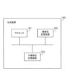
- FIG. 2 is a diagram showing the hardware included in the generation device.
- the generation device 100 includes a processor 101, a volatile storage device 102, and a nonvolatile storage device 103.
- the processor 101 controls the entire generation device 100.
- the processor 101 is a CPU (Central Processing Unit), an FPGA (Field Programmable Gate Array), a DSP (Digital Signal Processor), or the like.
- Processor 101 may be a multiprocessor.
- the generation device 100 may include a processing circuit.
- the generation device 100 may include a microcomputer or a SoC (System on Chip).
- the volatile storage device 102 is the main storage device of the generation device 100.
- the volatile storage device 102 is a RAM (Random Access Memory).
- the nonvolatile storage device 103 is an auxiliary storage device of the generation device 100.
- the nonvolatile storage device 103 is a ROM (Read Only Memory), an HDD (Hard Disk Drive), or an SSD (Solid State Drive).
- the generation device 100 includes a storage unit 110, an acquisition unit 120, a first element generation unit 130, a second element generation unit 140, a first drawing style generation unit 150, a second drawing style generation unit 160, and a diagram generation unit. 170, and an output section 180.
- the storage unit 110 may be realized as a storage area secured in the volatile storage device 102 or the nonvolatile storage device 103.
- Part of the acquisition unit 120, first element generation unit 130, second element generation unit 140, first drawing style generation unit 150, second drawing style generation unit 160, diagram generation unit 170, and output unit 180 Or all may be implemented by processing circuitry.
- Part or all may be realized as a module of a program executed by the processor 101.
- the program executed by the processor 101 is also referred to as a generation program.
- the generation program is recorded on a recording medium.
- the acquisition unit 120 acquires element setting information. For example, the acquisition unit 120 acquires element setting information from the storage unit 110. For example, the acquisition unit 120 acquires element setting information from an external device connectable to the generation device 100. Note that illustrations of external devices are omitted.
- Element setting information is information used when setting elements in a diagram.
- the element setting information includes an integer between 1 and 10, an arbitrary character string, an inclusion relationship, a connection relationship using an arrow, a connection relationship using a line, and a parallel relationship.
- the arrow may include a one-way arrow or a double-directed arrow.
- elements are blocks.
- the first element generation unit 130 generates first element information indicating the elements in the diagram based on the element setting information.
- the first element information is illustrated.
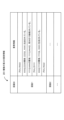
- FIG. 3 is a diagram showing an example of first element information.
- the first element generation unit 130 generates the number of blocks based on an integer between 1 and 10, inclusive.
- number of blocks: 4" is shown for the number of blocks.
- the first element generation unit 130 generates a block name based on an arbitrary character string.
- block name: XXX, YYY, ZZZ, AAA is shown for the block name.
- the first element generation unit 130 generates an inclusion relationship between blocks based on the inclusion relationship. For example, in FIG.
- the first element generation unit 130 generates connection relationships between blocks based on connection relationships indicated by arrows. For example, in FIG. 3, regarding the connection relationship, "Relationship between YYY and ZZZ: YYY and ZZZ are connected by a downward arrow.”
- the first element generation unit 130 generates an element of one drawing (for example, drawing ID "Drawing 1") as first element information.
- drawing ID "Drawing 1” an element of one drawing
- a diagram is shown created based on the elements of the diagram ID "Drawing 1".
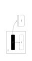
- FIG. 4 is a diagram showing an example of the diagram.
- the diagram in FIG. 4 is a diagram created based on the elements of the diagram ID “Drawing 1”.
- the first element generation unit 130 similarly generates other first element information based on the element setting information. For example, the first element generation unit 130 generates first element information indicating the element with the drawing ID “Drawing 2”. In this way, a plurality of pieces of first element information are generated by the first element generation unit 130. In FIG. 4, a plurality of pieces of first element information 200 are illustrated.
- the second element generation unit 140 generates at least one of an arbitrary part of elements and a relationship between arbitrary parts as second element information based on the first element information. do.
- the second element information is illustrated.
- FIG. 5 is a diagram showing an example of the second element information.
- the second element generation unit 140 generates the element "block XXX" as the second element information based on the first element information.
- the second element generation unit 140 generates the relationship between elements "Relationship between XXX and ZZZ: ZZZ is included in XXX" as the second element information based on the first element information. do.
- the second element generation unit 140 similarly generates other second element information based on other first element information.
- the second element generation unit 140 generates second element information corresponding to the drawing ID "Drawing 2" based on first element information corresponding to the drawing ID "Drawing 2". In this way, the second element generation unit 140 generates a plurality of pieces of second element information.
- FIG. 5 a plurality of pieces of second element information 201 are illustrated.
- the acquisition unit 120 acquires a drawing style list.
- the acquisition unit 120 acquires a drawing style list from the storage unit 110 or an external device.
- a list of drawing styles is illustrated below.
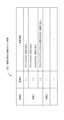
- FIG. 6 is a diagram showing an example of a drawing style list.
- the drawing style list 300 shows drawing styles.
- the drawing style list 300 shows drawing styles of block shapes, block colors, text colors within blocks, block borders, and connection lines.
- the drawing style list 300 may also indicate block sizes, block placement positions, fonts, line thicknesses, arrow shapes, and the like.
- the first drawing style generation unit 150 generates first drawing style information based on the first element information and the drawing style list 300.
- the first drawing style information is illustrated.
- FIG. 7 is a diagram showing an example of first drawing style information.
- generation of the first drawing style information will be specifically explained.
- the first drawing style generation unit 150 determines that the first drawing style information "block XXX" is a rectangle based on the first element information "block XXX” and the shape of the block in the drawing style list 300. ” is generated.
- the first drawing style generation unit 150 generates the first drawing style information "Block ZZZ” based on the first element information "Block ZZZ” and the border of the block in the drawing style list 300. This is a broken line.” is generated.
- the first drawing style generation unit 150 similarly generates other first drawing style information based on the other first element information and the drawing style list 300.
- the first drawing style generation unit 150 generates first drawing style information based on the drawing style list 300 and first element information indicating the element with the drawing ID “Drawing 2”. In this way, a plurality of pieces of first drawing style information are generated by the first drawing style generation unit 150. In FIG. 7, a plurality of pieces of first drawing style information 202 are illustrated.
- the second drawing style generation unit 160 generates information that is not included in the second element information among the first drawing style information as second drawing style information.
- the second drawing style information is illustrated.
- FIG. 8 is a diagram showing an example of the second drawing style information.
- FIG. 8 shows the second drawing style information generated by the second drawing style generation unit 160 corresponding to the drawing ID “Drawing 1”.
- the second drawing style generation unit 160 similarly generates other second drawing style information.
- the second drawing style generation unit 160 generates second drawing style information corresponding to the drawing ID “Drawing 2”.
- the second drawing style generation unit 160 generates a plurality of pieces of second drawing style information.
- FIG. 8 a plurality of pieces of second drawing style information 203 are illustrated.
- the diagram generation unit 170 generates a first diagram based on the first drawing style information.
- the first diagram may be generated as a raster image.
- the diagram generation unit 170 may generate the first diagram using the first element information and the first drawing style information.
- FIG. 9 is a diagram showing an example of the first diagram.
- the diagram in FIG. 9 is a first diagram generated based on the first drawing style information of the diagram ID “Drawing 1”.
- the diagram generation unit 170 generates a diagram for preventing the second drawing style information from being used as learning data as a second diagram based on the first drawing style information. For example, the diagram generation unit 170 generates a second diagram obtained by lightening the color of the second drawing style information in the first diagram. The second diagram is illustrated.
- FIG. 10 is a diagram showing an example of the second diagram.
- the diagram generation unit 170 lightens the color of block AAA, which is the second drawing style information. Further, for example, the diagram generation unit 170 lightens the color of "the connection line between block YYY and block ZZZ" which is the second drawing style information.
- FIG. 10 shows a second diagram. The colors of "block AAA" and "connection line between block YYY and block ZZZ" in the second diagram are light.
- a state in which the color is light is represented by a dotted line.
- the color of "AAA" in FIG. 10 is also lightened.
- the second drawing style information As the color of the second drawing style information becomes lighter, the second drawing style information is no longer used as learning data. That is, a diagram in which "block AAA" and "connection line between block YYY and block ZZZ" are not read into the learning device (ie, the second diagram) is taken as learning data.
- the diagram generation unit 170 may delete the second drawing style information in the first diagram.
- the second drawing style information is no longer used as learning data. That is, a diagram without "block AAA" and "connection line between block YYY and block ZZZ" is taken as learning data. Note that the second diagram may be generated as a raster image.
- the diagram generation unit 170 may convert the first diagram into a unified modeling language.
- the unified modeling language is UML (Unified Modeling Language).
- the diagram generator 170 may convert the second diagram into a unified modeling language.
- the diagram generation unit 170 generates the first diagram.
- the diagram generation unit 170 similarly generates other first diagrams.
- the diagram generation unit 170 generates the first diagram based on the first drawing style information of the diagram ID “Drawing 2”.
- a plurality of first diagrams are generated.
- the diagram generation unit 170 similarly generates another second diagram. This generates a plurality of second views.
- the output unit 180 outputs a plurality of first figures and a plurality of second figures.
- the output unit 180 outputs the plurality of first drawings and the plurality of second drawings to the storage unit 110 or an external device.
- the output unit 180 may output a plurality of first element information and a plurality of second element information. The plurality of first diagrams and the plurality of second diagrams are then used as learning data.
- FIG. 11 is a flowchart illustrating an example of processing executed by the generation device. Further, in FIG. 11, a case will be described in which one first diagram and one second diagram are generated.
- the acquisition unit 120 acquires element setting information.
- the first element generation unit 130 generates first element information based on the element setting information.
- the second element generation unit 140 generates second element information based on the first element information.
- the first drawing style generation unit 150 generates first drawing style information based on the first element information and the drawing style list 300.
- the second drawing style generation unit 160 generates information that is not included in the second element information among the first drawing style information as second drawing style information.
- the diagram generation unit 170 generates a first diagram based on the first drawing style information.
- the diagram generation unit 170 generates a diagram for preventing the second drawing style information from being used as learning data as a second diagram based on the first drawing style information.
- the output unit 180 outputs the first diagram and the second diagram to the storage unit 110.
- the generation device 100 automatically generates the first diagram (i.e., learning data). Therefore, the generation device 100 can reduce the burden on the user. Furthermore, the generation device 100 automatically generates the second diagram (ie, learning data). Therefore, the generation device 100 can reduce the burden on the user. Also, the second figure is different from the first figure. Therefore, in machine learning, different learning can be realized by using the second diagram.
- 100 generation device 101 processor, 102 volatile storage device, 103 non-volatile storage device, 110 storage section, 120 acquisition section, 130 first element generation section, 140 second element generation section, 150 first drawing style generation section, 160 second drawing style generation section, 170 diagram generation section, 180 output section, 200 plurality of first element information, 201 plurality of second element information, 202 plurality of first drawing style information, 203 plurality Second drawing style information, 300 drawing style list.
Landscapes
- Physics & Mathematics (AREA)
- General Physics & Mathematics (AREA)
- Engineering & Computer Science (AREA)
- Theoretical Computer Science (AREA)
- Processing Or Creating Images (AREA)
- Image Generation (AREA)
Priority Applications (2)
| Application Number | Priority Date | Filing Date | Title |
|---|---|---|---|
| PCT/JP2022/030734 WO2024034119A1 (ja) | 2022-08-12 | 2022-08-12 | 生成装置、生成方法、及び生成プログラム |
| JP2024538648A JP7592227B2 (ja) | 2022-08-12 | 2022-08-12 | 生成装置、生成方法、及び生成プログラム |
Applications Claiming Priority (1)
| Application Number | Priority Date | Filing Date | Title |
|---|---|---|---|
| PCT/JP2022/030734 WO2024034119A1 (ja) | 2022-08-12 | 2022-08-12 | 生成装置、生成方法、及び生成プログラム |
Publications (1)
| Publication Number | Publication Date |
|---|---|
| WO2024034119A1 true WO2024034119A1 (ja) | 2024-02-15 |
Family
ID=89851297
Family Applications (1)
| Application Number | Title | Priority Date | Filing Date |
|---|---|---|---|
| PCT/JP2022/030734 Ceased WO2024034119A1 (ja) | 2022-08-12 | 2022-08-12 | 生成装置、生成方法、及び生成プログラム |
Country Status (2)
| Country | Link |
|---|---|
| JP (1) | JP7592227B2 (https=) |
| WO (1) | WO2024034119A1 (https=) |
Citations (2)
| Publication number | Priority date | Publication date | Assignee | Title |
|---|---|---|---|---|
| JPH07287754A (ja) * | 1993-09-29 | 1995-10-31 | Sanyo Electric Co Ltd | 図表作成処理装置及び図表作成処理方法 |
| JPH1011599A (ja) * | 1996-06-26 | 1998-01-16 | Fuji Xerox Co Ltd | チャート図形処理装置 |
-
2022
- 2022-08-12 WO PCT/JP2022/030734 patent/WO2024034119A1/ja not_active Ceased
- 2022-08-12 JP JP2024538648A patent/JP7592227B2/ja active Active
Patent Citations (2)
| Publication number | Priority date | Publication date | Assignee | Title |
|---|---|---|---|---|
| JPH07287754A (ja) * | 1993-09-29 | 1995-10-31 | Sanyo Electric Co Ltd | 図表作成処理装置及び図表作成処理方法 |
| JPH1011599A (ja) * | 1996-06-26 | 1998-01-16 | Fuji Xerox Co Ltd | チャート図形処理装置 |
Also Published As
| Publication number | Publication date |
|---|---|
| JP7592227B2 (ja) | 2024-11-29 |
| JPWO2024034119A1 (https=) | 2024-02-15 |
Similar Documents
| Publication | Publication Date | Title |
|---|---|---|
| US7499952B2 (en) | Digital camera and image data recording method | |
| AU2011265341B2 (en) | Method, for an image slideshow | |
| CN106648555A (zh) | 一种页面的生成方法及装置 | |
| JP7043929B2 (ja) | 情報処理システムおよび情報処理方法 | |
| CN102273186A (zh) | 组合的图像与文本文档 | |
| WO2021208525A1 (zh) | 一种基于pdf文档的简化电子签名流程的方法、系统及装置 | |
| JP2017010069A (ja) | 情報処理装置 | |
| WO2024255394A1 (zh) | 一种凭证生成方法、装置、设备及可读存储介质 | |
| JP4865282B2 (ja) | 画像処理装置の制御方法、画像処理装置、プログラムコード及び記憶媒体 | |
| US7860892B2 (en) | Information processing apparatus, history file generation method and program | |
| WO2024244399A1 (zh) | 一种在网页打印pdf文件的方法、系统、存储介质、设备 | |
| JP2018037746A (ja) | 情報処理システム、情報処理装置、及び情報処理方法 | |
| JP6353261B2 (ja) | 情報処理装置、制御方法およびプログラム | |
| WO2021120664A1 (zh) | 一种异常inode的动态修复方法、系统及相关组件 | |
| WO2024034119A1 (ja) | 生成装置、生成方法、及び生成プログラム | |
| US9535908B2 (en) | Auto-retrieving to avoid data binding | |
| CN101853244A (zh) | 一种生成页码文件的方法及装置 | |
| CN105531765A (zh) | 基于语音生成和识别条形码信息的方法以及记录介质 | |
| JP6702015B2 (ja) | 情報処理システム、情報処理装置、及び情報処理方法 | |
| JP7484236B2 (ja) | 情報処理装置及び情報処理プログラム | |
| CN115640797A (zh) | 一种生成流程签核文件pdf的方法 | |
| US20140245138A1 (en) | Document conversion and printing | |
| US12511849B2 (en) | Method for improving visual quality of reality service content, host, and computer readable storage medium | |
| JP2006171913A (ja) | 情報処理装置、情報処理方法、ならびにプログラム、記憶媒体 | |
| JP2004145736A (ja) | 文字認識装置および文字認識データ出力方法およびプログラムおよび記録媒体 |
Legal Events
| Date | Code | Title | Description |
|---|---|---|---|
| 121 | Ep: the epo has been informed by wipo that ep was designated in this application |
Ref document number: 22955034 Country of ref document: EP Kind code of ref document: A1 |
|
| ENP | Entry into the national phase |
Ref document number: 2024538648 Country of ref document: JP Kind code of ref document: A |
|
| NENP | Non-entry into the national phase |
Ref country code: DE |
|
| 122 | Ep: pct application non-entry in european phase |
Ref document number: 22955034 Country of ref document: EP Kind code of ref document: A1 |